lwrm
TRANSCRIPT

8/20/2019 lwrm
http://slidepdf.com/reader/full/lwrm 1/226
GOVERNMENT OF INDIAMINISTRY OF RAILWAYS
MANUAL OF INSTRUCTIONS ON
LONG WELDED RAILS1996
Second Reprint 2005
Embodying all advance correction slips upto
number 8 dated 14-01-2002
For official use only
RESEARCH DESIGNS AND STANDARDS ORGANISATION
LUCKNOW - 226011
8/20/2019 lwrm
http://slidepdf.com/reader/full/lwrm 2/226
(i)
8/20/2019 lwrm
http://slidepdf.com/reader/full/lwrm 3/226
MANUAL OF INSTRUCTIONS ON LONG WELDED RAILS 1996
(SECOND REPRINT)
INTRODUCTION
“Manual of Instructions on Long Welded Rails” was issued in 1979. This Manual
contained instructions for the installation and maintenance of Long Welded Rails
(LWR) and Continuous Welded Rails (CWR) on Indian Railways.
The Revised Manual issued in 1996 incorporated all the correction slips issued to
the Manual of 1979 and also changes required due to use of 60kg rails, adoption of
Alumino Thermic (SKV process)/Mobile Gas Pressure/Flash Butt welding, mechanized
maintenance & adoption of Indian Railways Permanent Way Manual (IRPWM) in
place of Indian Railways Way and Works Manual (IRWWM) etc.
To date, eight correction slips have been issued to the Revised Manual. This
Manual is the second reprint of the Manual issued in 1996 and incorporates all these
correction slips. This Manual shall have the same authority as IRPWM. The Chief
Engineers may issue supplementary instructions from time to time to suit local workingconditions.
The recommendations in the Manual have been framed for use of standard sleepers
and fastenings already approved. Any other type of sleepers and fastenings may be
used in LWR/CWR only after the same are approved or specifically authorized by the
Chief Engineer.
(i)
8/20/2019 lwrm
http://slidepdf.com/reader/full/lwrm 4/226
(ii)
8/20/2019 lwrm
http://slidepdf.com/reader/full/lwrm 5/226
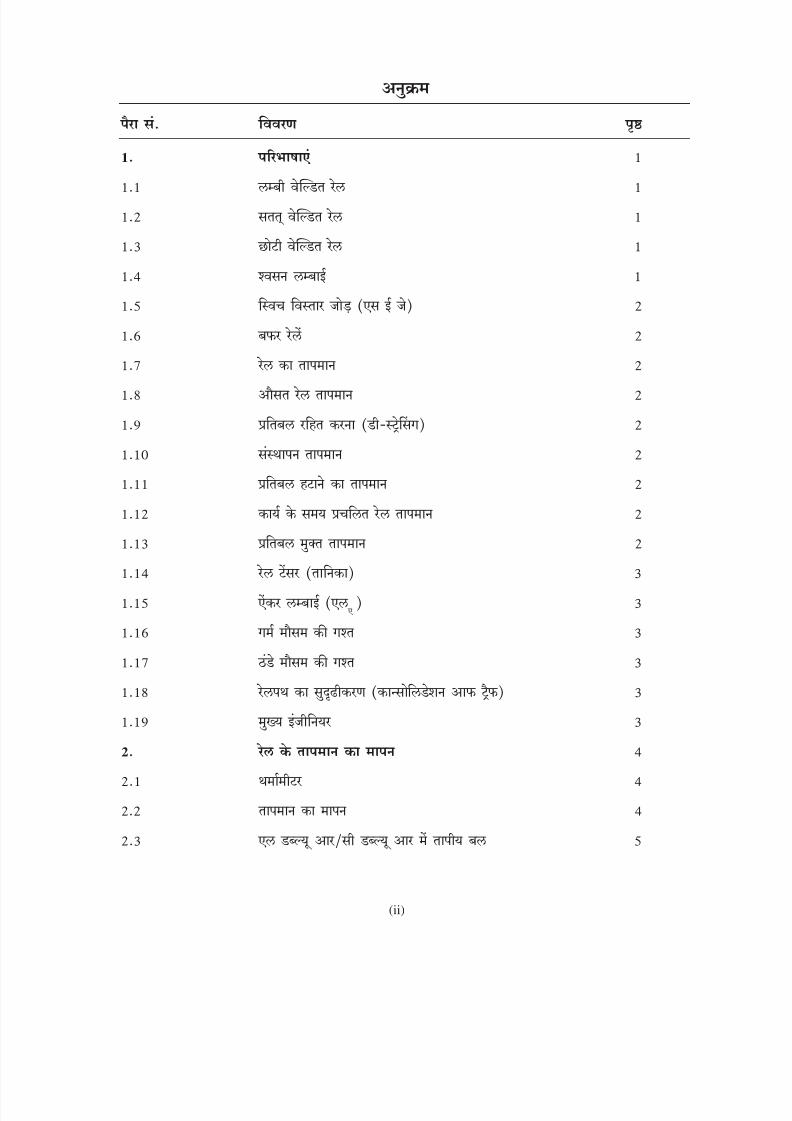
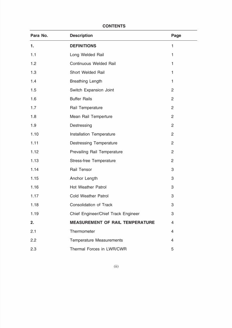
CONTENTS
Para No. Description Page
1. DEFINITIONS 1
1.1 Long Welded Rail 1
1.2 Continuous Welded Rail 1
1.3 Short Welded Rail 1
1.4 Breathing Length 1
1.5 Switch Expansion Joint 2
1.6 Buffer Rails 2
1.7 Rail Temperature 2
1.8 Mean Rail Temperture 2
1.9 Destressing 2
1.10 Installation Temperature 2
1.11 Destressing Temperature 2
1.12 Prevailing Rail Temperature 2
1.13 Stress-free Temperature 2
1.14 Rail Tensor 3
1.15 Anchor Length 3
1.16 Hot Weather Patrol 3
1.17 Cold Weather Patrol 3
1.18 Consolidation of Track 3
1.19 Chief Engineer/Chief Track Engineer 3
2. MEASUREMENT OF RAIL TEMPERATURE 4
2.1 Thermometer 4
2.2 Temperature Measurements 4
2.3 Thermal Forces in LWR/CWR 5
(ii)

8/20/2019 lwrm
http://slidepdf.com/reader/full/lwrm 6/226
(iii)
8/20/2019 lwrm
http://slidepdf.com/reader/full/lwrm 7/226
Para No. Description Page
3. PERMITTED LOCATIONS FOR LWR/CWR 5
3.1 General Considerations for Laying LWR/CWR 5
3.2 Alignment 5
3.3 Gradients 6
3.4 Approval of Chief Engineer 6
4. TRACK STRUCTURE FOR LWR/CWR 6
4.1 Formation 6
4.2 Ballast Cushion and Section 6
4.3 Sleepers & Fastenings 7
4.4 Rails 8
4.5 Miscellaneous 8
5. LAYING OF LWR & CWR 12
5.1 Survey 12
5.2 Temperature Records 13
5.3 Materials Required 13
5.4 Preliminary Works 14
5.5 Welding of Rails to form LWR 14
5.6 Gaps at SEJ 15
5.7 Destressing of LWR 15
5.8 Joining LWRs into CWR 19
5.9 Reference Marks 21
6. MAINTENANCE OF LWR/CWR 21
6.1 General 21
(iii)

8/20/2019 lwrm
http://slidepdf.com/reader/full/lwrm 8/226
(iv)
8/20/2019 lwrm
http://slidepdf.com/reader/full/lwrm 9/226
Para No. Description Page
6.2 Regular Track Maintenance 21
6.3 Special Track Maintenance 24
6.4 Destressing during Maintenance 26
6.5 Special Equipment for Maintenance of LWR/CWR 27
7. UNUSUAL OCCURRENCES 27
7.1 List of Unusual Occurrences 27
7.2 Rectification of Rail Fractures 27
7.3 Damage to Switch Expansion Joint 29
7.4 Buckling of Track 30
7.5 Breaches, Temporary Girders and Diversions 31
8. INSPECTION AND RECORDS 31
8.1 Inspection 31
8.2 Records 32
9. DUTIES, RESPONSIBILITIES, 33
AND TRAINING OF STAFF
9.1 Duties and Responsibilities 33
9.2 Training 38
9.3 ‘‘Do’s’’ and ‘‘Dont’s’’ 38
(iv)

8/20/2019 lwrm
http://slidepdf.com/reader/full/lwrm 10/226
I
II
III
IV
V
VI
VII
VIII
IX
X X X
XI
XII
XIII XIII
XIV
(v)

8/20/2019 lwrm
http://slidepdf.com/reader/full/lwrm 11/226
LIST OF ANNEXURES
Annexure No. Description Page
I Breathing Lengths 39-41
II Supplementary Instructions for Laying & 42-43Maintenance of LWR on
CST-9 sleepers on BG
III Schedules of Speed Restrictions 44
IV Handling Instructions for 90 UTS and HH Rails 45-47
V Gaps at SEJ for Various Rail 48-66Temperatures and Track Structure
VI Work Chart and Authorised Level 67-69of Supervision
VII Extension Table 70
VIII Destressing Operation of LWR/CWRs 71Panels without the use of Rail Tensor
IX Instructions for Laying and 72-74Maintenance of Buffer Rails at theend of LWRs/CWRs
X A Hot Weather Patrolling 75-76X B Cold Weather Patrolling 77X C Mobile Watchman 78
XI Details of Structure of LWR/CWR as laid 79-80
XII Annual Record of LWR/CWR Maintenance 81-82and Performance
XIII A Chart of Movement of LWR/CWR 83
XIII B Chart of Movement in 84Central Portion of LWR/CWR
XIV Do’s and Dont’s of LWR for PWM, 85-86Mates and Keymen
(v)
8/20/2019 lwrm
http://slidepdf.com/reader/full/lwrm 12/226
V
(iii)
(iv)
(iii)
(viii)
(viii)
(viii)
(vi)
8/20/2019 lwrm
http://slidepdf.com/reader/full/lwrm 13/226
LIST OF FIGURES
Figure No. Description Page
1.1 Long Welded Rails 1
A.5(a) Hysteresis Curve showing the Movement 50of ends of Tongue/Stock Rail of SEJ
A.5(b) Gap at SEJ as per Example given in 52Annexure-V
1.7 Map of India showing Rail Temperature Zones 87
4.2.1(a) Ballast Profile (Single Line BG) 88
4.2.1(b) Ballast Profile (Single Line MG) 89
4.2.1(c) Ballast Profile (Double Line BG) 90
4.2.1(d) Ballast Profile (Double Line MG) 91
4.4.3(a) 1 m Long Special Fishplate for Clamped Joints (BG) 92
4.4.3(b) Screw Clamp for fixing 1 m Long Special Fishplate 93
4.4.3(c) Details of Joggled Fishplate and Position of Clamp 94
4.5.7.1(iii) Welded Rails on Bridge (Pier to Pier) 95
4.5.7.1(iv) LWR/CWR on Bridge with SEJ at the far 95
end approach of the Bridge
5.1.3 Proposals for Laying LWR and CWR 96
5.3(iii) Slotted Fishplate 97
5.3(viii)(a) Rollers for BG 98
5.3(viii)(b1) Side Roller/Support Arm 99
5.3(viii)(b2) Side Roller/Support Arm 1005.6 Setting of Gap at SEJ at 101
Destressing Temperature (td)
5.7.3 Destressing of LWR with the use of Rail Tensor 102
5.8 Conversion of existing LWRs into CWR 103
7.2.4, 7.2.5 Temporary & Permanent Repairs of 104Rail Fractures with the use of Rail Tensor
A.9(a) Sleeper Spacings under 6.5 m Buffer Rails (BG) 105
A.9(b) Sleeper Spacings under 6.0 m Buffer Rails (MG) 106(vi)
8/20/2019 lwrm
http://slidepdf.com/reader/full/lwrm 14/226
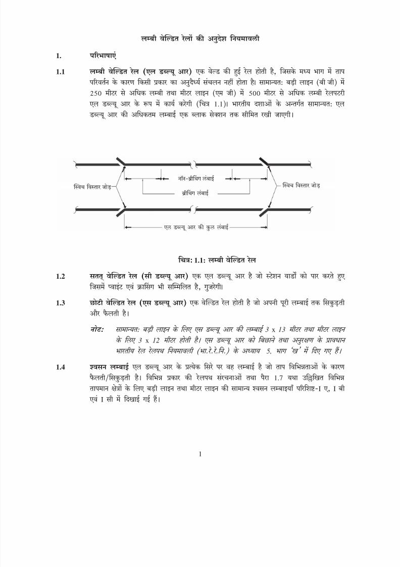
1.
1.1
1.1
1.1:
1.2
1.3
3 x 13 3 x 12 5,
1.4 1.7 I I I
1
8/20/2019 lwrm
http://slidepdf.com/reader/full/lwrm 15/226
1. DEFINITIONS
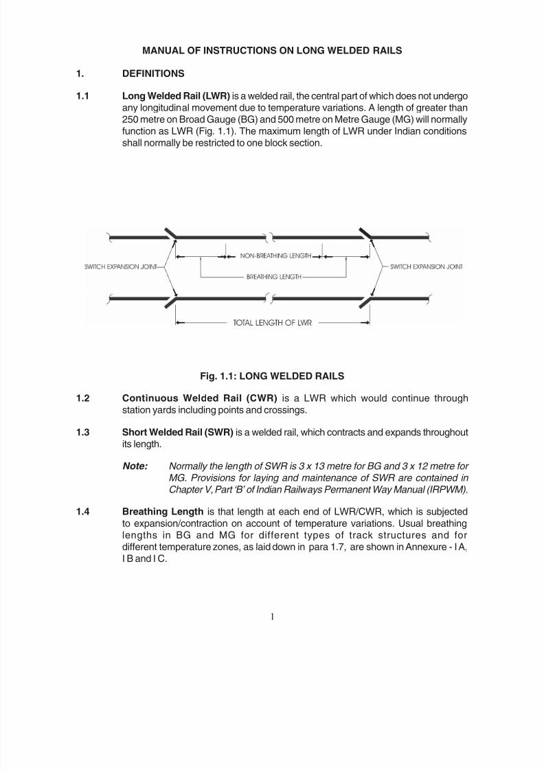
1.1 Long Welded Rail (LWR) is a welded rail, the central part of which does not undergoany longitudinal movement due to temperature variations. A length of greater than
250 metre on Broad Gauge (BG) and 500 metre on Metre Gauge (MG) will normallyfunction as LWR (Fig. 1.1). The maximum length of LWR under Indian conditionsshall normally be restricted to one block section.
Fig. 1.1: LONG WELDED RAILS
1.2 Continuous Welded Rail (CWR) is a LWR which would continue throughstation yards including points and crossings.
1.3 Short Welded Rail (SWR) is a welded rail, which contracts and expands throughoutits length.
Note: Normally the length of SWR is 3 x 13 metre for BG and 3 x 12 metre for MG. Provisions for laying and maintenance of SWR are contained in Chapter V, Part ‘B’ of Indian Railways Permanent Way Manual (IRPWM).
1.4 Breathing Length is that length at each end of LWR/CWR, which is subjected
to expansion/contraction on account of temperature variations. Usual breathinglengths in BG and MG for different types of track structures and fordifferent temperature zones, as laid down in para 1.7, are shown in Annexure - I A,I B and I C.
MANUAL OF INSTRUCTIONS ON LONG WELDED RAILS
1
8/20/2019 lwrm
http://slidepdf.com/reader/full/lwrm 16/226
1.5 1.1
1.6
1.7 2.1
1.7
1.8
1.9
1.10
1.11
1.13
i) 52
50
100
ii) 50
1.12
1.13
2
8/20/2019 lwrm
http://slidepdf.com/reader/full/lwrm 17/226
1.5 Switch Expansion Joint (SEJ) is an expansion joint installed at eachend of LWR/CWR to permit expansion/contraction of the adjoiningbreathing lengths due to temperature variations (Fig. 1.1).
1.6 Buffer Rails are, a set of rails provided in lieu of SEJ at the ends of LWR/CWRto allow expansion/contraction of adjoining breathing lengths due to temperature
variations. These will be laid with prior approval of Chief Engineer at locationswhere provision of SEJ is not permitted. Buffer rails may also be temporarilylaid to facilitate maintenance/renewal operations.
1.7 Rail Temperature is the temperature of the rail at site as recorded by anapproved type of rail thermometer as laid down in para 2.1. This is differentfrom ambient temperature which is the temperature of air in shade at the sameplace.
Note: Tracks on Indian Railways have been divided into four rail temperature zones as shown in the “Map of India showing Rail Temperature Zones"
at Fig. 1.7.
1.8 Mean Rail Temperature (tm) for a section, is the average of the maximum and
minimum rail temperatures recorded for the section.
1.9 Destressing is the operation undertaken with or without rail tensor to secure stress-free conditions in the LWR/CWR at the desired/specified rail temperature.
1.10 Installation Temperature (ti) is the average rail temperature during the
process of fastening the rails to the sleepers at the time of installation of theLWR/CWR.
1.11 Destressing Temperature (td) is the average rail temperature during theperiod of fastening the rails to the sleepers after destressing LWR without the
use of rail tensor. If rail tensor is used, td for all practical purposes is equal to
to as defined in para 1.13. Range of t
d or t
o shall be within the limits of rail
temperature shown below:-
Rail Section Range
i) 52kg & heavier tm+50C to t
m+100C
ii) Others tm to t
m+50C
1.1.2 Prevailing Rail Temperature (tp) is the rail temperature prevailing at the time whenany operation connected with destressing is carried out.
1.13 Stress-free Temperature (to) is the rail temperature at which the rail is free
of thermal stress. When tensors are utilised for the destressing operation thework has to be carried out at t
p, which shall be lower than stress-free temperature.
The extension to be applied by the tensor shall be calculated from thefollowing formula:-
2
8/20/2019 lwrm
http://slidepdf.com/reader/full/lwrm 18/226
x x
1.14
1.15
2.5
4.5
1.16
200
1.17
1.18
i)
3,00,000 1,00,000
50,000 20,000
ii) 50,000 20,000
iii)
iv)
1.19
3
8/20/2019 lwrm
http://slidepdf.com/reader/full/lwrm 19/226
Extension = L α (t o - t
p )
where ‘L’ is the length of segment of the rail to which the extension is applied and ‘ α ’ is the coefficient of linear expansion of rail steel.
1.14 Rail Tensor is a hydraulic or mechanical device used for stretching the rail
physically.
1.15 Anchor Length (la) is the length of track required to resist the pull exerted on
rails by the rail tensor at temperature tp. For practical purposes, this may be
taken as equal to 2.5 metre per degree celsius of (to - t
p) for BG and 4.5 metre per
degree celsius of (to - t
p) for MG.
1.16 Hot Weather Patrol is the patrol carried out when the rail temperature exceedstd + 200C.
1.17 Cold Weather Patrol is the patrol carried out during cold months of the year in
specified sections as per instructions of Chief Engineer.
1.18 Consolidation of Track is the process of building up ballast resistance to thetendency of movement of sleeper either initially before laying LWR or making upsubsequent loss of resistance by anyone of the following:-
i) For track structures consisting of sleepers other than concrete sleepers -
a) Passage of at least 3,00,000 gross tonnes of traffic on BG orat least 1,00,000 gross tonnes of traffic on MG when compaction
of ballast is done using hand operated compactors/consolidators orrammers.
b) Passage of at least 50,000 gross tonnes of traffic on BG or at least 20,000gross tonnes of traffic on MG or a period of two days, whichever is later,when compaction is done by means of mechanised shoulder and cribcompactor.
ii) For the track structure consisting of concrete sleepers, passage of at least50,000 gross tonnes of traffic on BG or at least 20,000 gross tonnes of trafficon MG or a period of two days whichever is later.
iii) Atleast one round of stabilisation by Dynamic Track Stabiliser (DTS).
iv) For newly laid LWR/CWR, at least three rounds of packing, last two of whichshould be with on-track tamping machines.
1.19 The term ‘Chief Engineer’ includes ‘Chief Track Engineer’ on Railways wherelatter post exists.
3
8/20/2019 lwrm
http://slidepdf.com/reader/full/lwrm 20/226
2.
2.1
2.1.1
i) 25 30
ii)
8
iii) 24 7
iv)
2.1.2
2.2
2.2.1 8 10
5
4
8/20/2019 lwrm
http://slidepdf.com/reader/full/lwrm 21/226
2. MEASUREMENT OF RAIL TEMPERATURE
2.1 THERMOMETER
2.1.1 The following are the types of approved thermometers for measuring rail temperature:-
i) Embedded type - This is an ordinary thermometer inserted in a cavity formedin a piece of rail-head, the cavity filled with mercury and sealed. The rail pieceis exposed to the same conditions as the rail inside the track. This type of
thermometer takes 25 to 30 minutes for attaining temperature of the rail.
ii) Dial type - This is a bi-metallic type thermometer, which is provided with magnetfor attaching it to the rail. The thermometer is attached on the shady side of theweb of the rail. A steady recording of the rail temperature is reached within 8minutes.
iii) Continuous recording type - It consists of a graduated chart mountedon a disc which gets rotated by a winding mechanism at a constant speed tocomplete one revolution in 24 hours or 7 days as applicable giving a continuousrecord of rail temperature. The sensing element is attached to the web of the
rail and connected to the recording pen, through a capillary tube which is filledwith mercury.
iv) Any other type of thermometer approved by RDSO/Chief Engineer.
2.1.2 Where a number of thermometers are used to measure the rail temperature at oneplace, as in case of laying of LWR, destressing etc., any of the thermometer showing
erratic readings, appreciably different from the other adjoining thermometers, shallbe considered as defective.
2.2 TEMPERATURE MEASUREMENTS
2.2.1 Zonal Railway should nominate 8 to 10 stations in their railway in a manner as to givethe representative sample of the temperature variations on the Zonal Railway for theregion allotted to each station. These stations shall be the existing PWIs offices. Onthese stations rail temperature records shall be built up using preferably a well
calibrated continuous recording type thermometer. The maximum and minimum rail
temperature for a continuous period of at least 5 years shall be ascertained and themean rail temperature (t
m) for the region arrived at. These temperature records shall
be analysed to assess the probable availability of time periods during differentseasons of the year for track maintenance, destressing operations and requirementsof hot/cold weather patrolling etc. Rail thermometer shall also be available with eachGang and sectional PWIs to enable the Gangs to work within the prescribed
temperature ranges.
4
8/20/2019 lwrm
http://slidepdf.com/reader/full/lwrm 22/226
2.3
x x x
2.15 x 10⁶
1.152 x 10⁻⁵ / 0
3.
3.1
3.1.1
3.1.2
3.1.3
3.2
3.2.1 440
3.2.2 875 100 600 1500
5
8/20/2019 lwrm
http://slidepdf.com/reader/full/lwrm 23/226
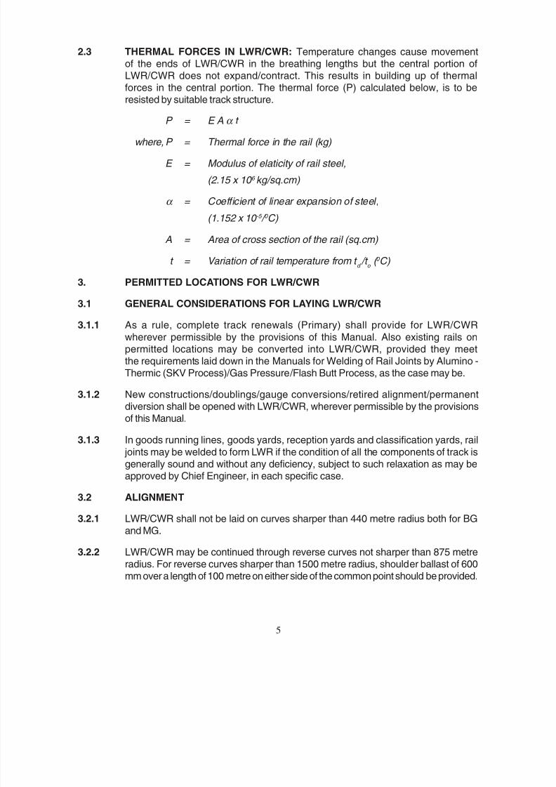
2.3 THERMAL FORCES IN LWR/CWR: Temperature changes cause movementof the ends of LWR/CWR in the breathing lengths but the central portion ofLWR/CWR does not expand/contract. This results in building up of thermalforces in the central portion. The thermal force (P) calculated below, is to beresisted by suitable track structure.
P = E A α t
where, P = Thermal force in the rail (kg)
E = Modulus of elaticity of rail steel,
(2.15 x 10 6 kg/sq.cm)
α = Coefficient of linear expansion of steel,
(1.152 x 10 -5 / 0 C)
A = Area of cross section of the rail (sq.cm)
t = Variation of rail temperature from t d /t
o ( 0 C)
3. PERMITTED LOCATIONS FOR LWR/CWR
3.1 GENERAL CONSIDERATIONS FOR LAYING LWR/CWR
3.1.1 As a rule, complete track renewals (Primary) shall provide for LWR/CWR
wherever permissible by the provisions of this Manual. Also existing rails onpermitted locations may be converted into LWR/CWR, provided they meetthe requirements laid down in the Manuals for Welding of Rail Joints by Alumino -
Thermic (SKV Process)/Gas Pressure/Flash Butt Process, as the case may be.
3.1.2 New constructions/doublings/gauge conversions/retired alignment/permanentdiversion shall be opened with LWR/CWR, wherever permissible by the provisionsof this Manual.
3.1.3 In goods running lines, goods yards, reception yards and classification yards, rail
joints may be welded to form LWR if the condition of all the components of track isgenerally sound and without any deficiency, subject to such relaxation as may beapproved by Chief Engineer, in each specific case.
3.2 ALIGNMENT
3.2.1 LWR/CWR shall not be laid on curves sharper than 440 metre radius both for BGand MG.
3.2.2 LWR/CWR may be continued through reverse curves not sharper than 875 metreradius. For reverse curves sharper than 1500 metre radius, shoulder ballast of 600mm over a length of 100 metre on either side of the common point should be provided.
5

8/20/2019 lwrm
http://slidepdf.com/reader/full/lwrm 24/226
3.3
3.3.1 1:100
3.3.2 419 4 0.4
4000 3000 2500
2500
3.4 5.1.3
4.
4.1
4.2 250
130 100 300 150 200 4.2.1 ( ) ( )
6

8/20/2019 lwrm
http://slidepdf.com/reader/full/lwrm 25/226
3.3 GRADIENTS
3.3.1 The steepest permitted grade shall be 1:100.
3.3.2 A vertical curve shall be provided at the junction of the grade when the algebraicdifference between the grades is equal to or more than 4 mm per metre or 0.4 percent,
as laid down in para 419 of IRPWM.The minimum radius of the vertical curve shall be kept as under:
Broad Gauge Metre Gauge
Group Minimum radius Group Minimum radius
A 4000 metre
B 3000 metre All routes 2500 metre
C, D & E 2500 metre
3.4 Approval of Chief Engineer : Installation of LWR/CWR or change in its constitutionat a later stage shall have the approval of the Territorial Chief Engineer concerned ineach case, on a detailed plan prepared in accordance with para 5.1.3. However, for
any deviation from the provisions of this Manual, the approval of Chief Engineer shallbe obtained.
4. TRACK STRUCTURE FOR LWR/CWR
4.1 FORMATION
LWR/CWR shall be laid on stable formation. Formation width shall be conforming tothe extant instructions.
4.2 BALLAST CUSHION AND SECTION: The minimum clean stone ballast cushion(below the bottom of the sleeper) of 250 mm shall be provided at the time of installation
of LWR/CWR. Where speeds in excess of 130 km/h on BG or 100 km/h on MG areto be introduced, at least 300 mm ballast cushion or 200 mm ballast cushion over150 mm of sub-ballast shall be provided. The profile of ballast section shall be asshown in Fig.4.2.1 (a) to (d). The ballast section and cushion provided for LWR/
CWR shall be continued over SEJ and upto 3 rails beyond it wherever it is followedby SWR/fishplated track.
6
8/20/2019 lwrm
http://slidepdf.com/reader/full/lwrm 26/226
4.3
4.3.1
i)
ii) 130
160
4.3.2
4.3.2
i)
ii)
iii)
iv) 9
9 130
9 II
130 100
4.3.3
100
75
100
7
{
{

8/20/2019 lwrm
http://slidepdf.com/reader/full/lwrm 27/226
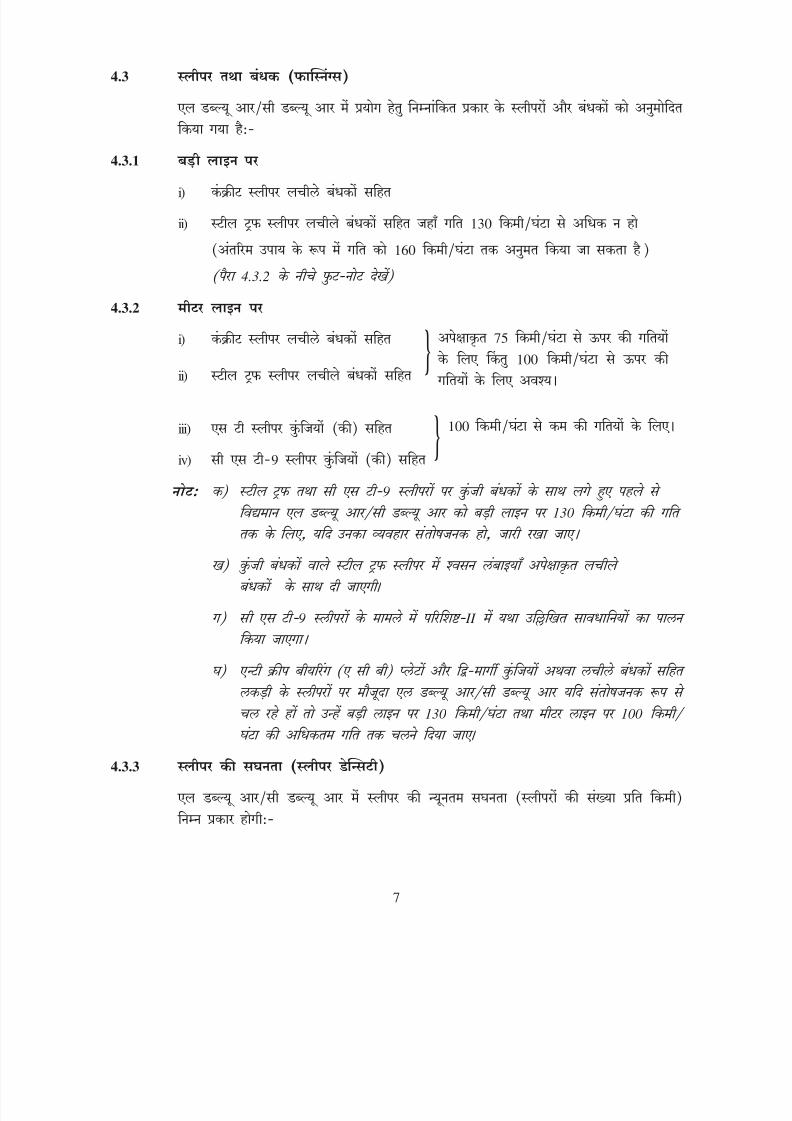
4.3 SLEEPERS & FASTENINGS
Following types of sleepers and fastenings are approved for use in LWR/ CWR:-
4.3.1 On Broad Gauge
i) Concrete sleepers with elastic fastenings
ii) Steel trough sleepers with elastic fastenings for speeds not exceeding 130km/h (as an interim measure speed up to 160 km/h may be allowed)
(See foot-notes below para 4.3.2)
4.3.2 On Metre Gauge
i) Concrete sleeperswith elastic fastenings
ii) Steel trough sleeperswith elastic fastenings
iii) ST sleepers with keys
iv) CST-9 sleepers with keys
Notes: a) LWR/CWR already existing on steel trough sleepers and CST-9
sleepers with key fastenings for speeds upto 130 km/h on BG, if behaving satisfactorily, may be continued.
b) On steel trough sleepers with key fastenings, the breathing lengths shall preferably be provided with elastic fastenings.
c) In case of CST-9 sleepers, precautions as indicated in Annexure-II shall be adhered to.
d) Existing LWRs/CWRs on wooden sleepers with anti creep bearing (ACB)
plates & two way keys or elastic fastenings, if behaving satisfactorily,may be continued for maximum speed of 130 km/h on BG and 100 km /h on MG.
4.3.3 Sleeper density
The minimum sleeper density (number of sleepers/km) in LWR/CWR shall be asfollows:-
Preferably for speeds above75 km/h but a must forspeeds above 100 km/h.
For speeds not exceeding100 km/h.
7
{
{
8/20/2019 lwrm
http://slidepdf.com/reader/full/lwrm 28/226
i) I II 1310
ii) III IV 1540
iii) 1540
4.4
4.4.1 i)
ii)
9052 60
7590
60
4.4.2
i)
ii)
4.4.3
1
4.4.3( ), ( ) ( ) III
4.5
4.5.1
8
8/20/2019 lwrm
http://slidepdf.com/reader/full/lwrm 29/226
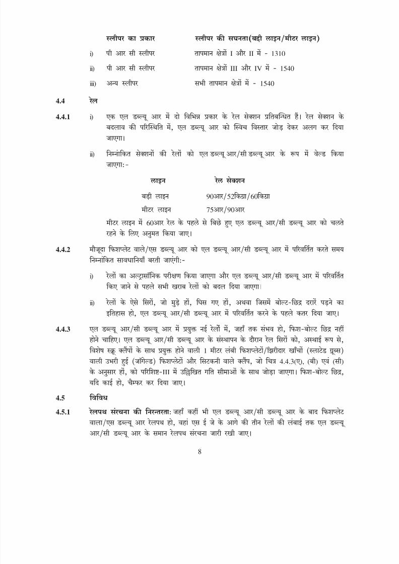
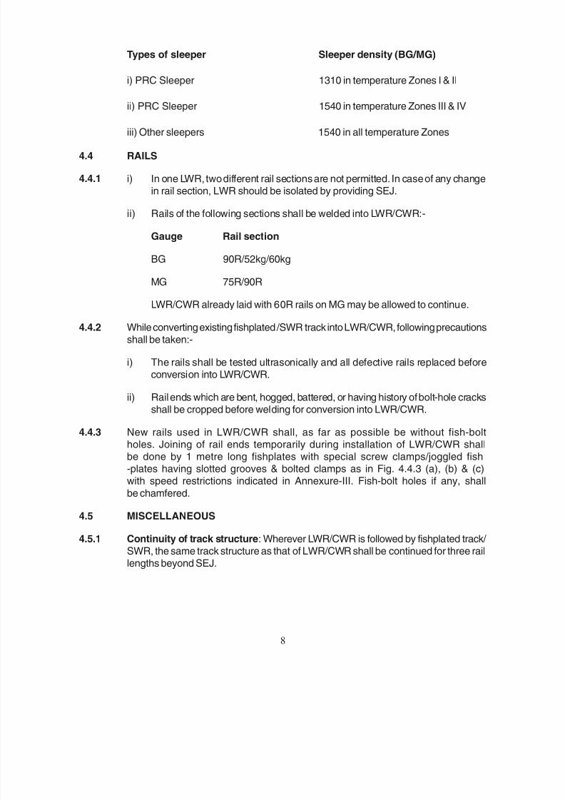
Types of sleeper Sleeper density (BG/MG)
i) PRC Sleeper 1310 in temperature Zones I & II
ii) PRC Sleeper 1540 in temperature Zones III & IV
iii) Other sleepers 1540 in all temperature Zones
4.4 RAILS
4.4.1 i) In one LWR, two different rail sections are not permitted. In case of any changein rail section, LWR should be isolated by providing SEJ.
ii) Rails of the following sections shall be welded into LWR/CWR:-
Gauge Rail section
BG 90R/52kg/60kg
MG 75R/90R
LWR/CWR already laid with 60R rails on MG may be allowed to continue.
4.4.2 While converting existing fishplated /SWR track into LWR/CWR, following precautionsshall be taken:-
i) The rails shall be tested ultrasonically and all defective rails replaced before
conversion into LWR/CWR.
ii) Rail ends which are bent, hogged, battered, or having history of bolt-hole cracksshall be cropped before welding for conversion into LWR/CWR.
4.4.3 New rails used in LWR/CWR shall, as far as possible be without fish-boltholes. Joining of rail ends temporarily during installation of LWR/CWR shallbe done by 1 metre long fishplates with special screw clamps/joggled fish-plates having slotted grooves & bolted clamps as in Fig. 4.4.3 (a), (b) & (c)with speed restrictions indicated in Annexure-III. Fish-bolt holes if any, shall
be chamfered.
4.5 MISCELLANEOUS
4.5.1 Continuity of track structure: Wherever LWR/CWR is followed by fishplated track/ SWR, the same track structure as that of LWR/CWR shall be continued for three raillengths beyond SEJ.
8

8/20/2019 lwrm
http://slidepdf.com/reader/full/lwrm 30/226
4.5.2
4.5.3
4.5.3.1
4.5.4 G3(L)
4.5.5 0.5 3500
4.5.6
4.5.7
i) 4.5.7.1 20
ii) 36
4.5.7.1 i) 30.5
1
9

8/20/2019 lwrm
http://slidepdf.com/reader/full/lwrm 31/226
4.5.2 Level crossings: Level crossings situated in LWR/CWR territory shall not fall withinthe breathing lengths.
4.5.3 Points and Crossings: LWR/CWR shall not normally be taken through pointsand crossings. Three normal rail lengths shall be provided between stock rail
joint (SRJ) and SEJ as well as between the crossing and SEJ. These normal rail
lengths shall be provided with elastic rail clips/anchors to arrest creep. However,where concrete sleeper turnouts are laid, instead of three normal rail lengths, onethree rail panel shall be provided between SEJ and SRJ as well as between heel ofcrossing and SEJ.
4.5.3.1 LWR/CWR shall not be taken through points & crossings. For any exceptions in thisregard, special arrangements shall have the prior approval of RDSO.
4.5.4 Glued Joints: All insulations for track circuiting in LWR/CWR shall be done byproviding glued joints G3(L) type.
4.5.5 Location of SEJ: The exact location of SEJ shall be fixed taking into account the
location of various obligatory points such as level crossings, girder bridges, pointsand crossings, gradients, curves and insulated joints. SEJ with straight tongue andstock shall not be located on curves sharper than 0.5 degree (3500 m radius) as faras possible. SEJ shall not be located on transition of curves.
4.5.6 Bridges with ballasted deck (without bearing): LWR/CWR can be continuedover bridges without bearings like slabs, box culverts and arches.
4.5.7 Bridges with/without ballasted deck
i) LWR/CWR shall not be continued over bridges with overall length as specified inpara 4.5.7.1 for BG and not more than 20 metre for MG.
ii) Bridges on which LWR/CWR is not permitted/provided shall be isolated by aminimum length of 36 metre well anchored track on either sides.
4.5.7.1 i) Bridges provided with rail-free fastenings (single span not exceeding 30.5
metre and having sliding bearings on both ends)
Overall length of the bridge should not exceed the maximum as provided in Table-1with following stipulations:-
9

8/20/2019 lwrm
http://slidepdf.com/reader/full/lwrm 32/226
50
i)
ii)
50
4.5.7.1 ii) 30.5
1
4.5.7.1(i)
10

8/20/2019 lwrm
http://slidepdf.com/reader/full/lwrm 33/226
a) Rail-free fastenings shall be provided throughout the length of the bridge betweenabutments.
b) The approach track upto 50 m on both sides shall be well anchored by providingany one of the following:-
i) ST sleepers with elastic fastenings
ii) PRC sleepers with elastic rail clips with fair ‘T’ or similar type creepanchors.
c) The ballast section of approach track upto 50 metre shall be heaped upto thefoot of the rail on the shoulders and kept in well compacted and consolidatedcondition during the months of extreme summer and winter.
4.5.7.1 ii) Bridges provided with rail-free fastenings and partly box-anchored (with
single span not exceeding 30.5 metre and having sliding bearings at both
ends)
Overall length of the bridge should not exceed the maximum as provided in Table-1with following stipulations:-
a) On each span, 4 central sleepers shall be box-anchored with fair ‘V’ or similartype creep anchors and the remaining sleepers shall be provided with rail-free
fastenings.
b) The bridge timbers laid on girders shall not be provided with through notch but
shall be notched to accommodate individual rivet heads.
c) The track structure in the approaches shall be laid and maintained to thestandards as stated in item 4.5.7.1 (i) (b) and (c) above.
d) The girders shall be centralised with reference to the location strips on thebearing, before laying LWR/CWR.
e) The sliding bearings shall be inspected during the months of March and Octobereach year and cleared of all foreign materials. Lubrication of the bearings shallbe done once in two years.
10

8/20/2019 lwrm
http://slidepdf.com/reader/full/lwrm 34/226
1
4.5.7.1 (i) (ii)
4.5.7.1(i) 4.5.7.1(ii)
I 60 30 77
52 90 45 90
II 60 11 42
52 90 27 58
III 60 11 23
52 90 27 43
IV 60 11 23
52 90 27 43
4.5.7.1 iii) 4.5.7.1(iii)
11
8/20/2019 lwrm
http://slidepdf.com/reader/full/lwrm 35/226
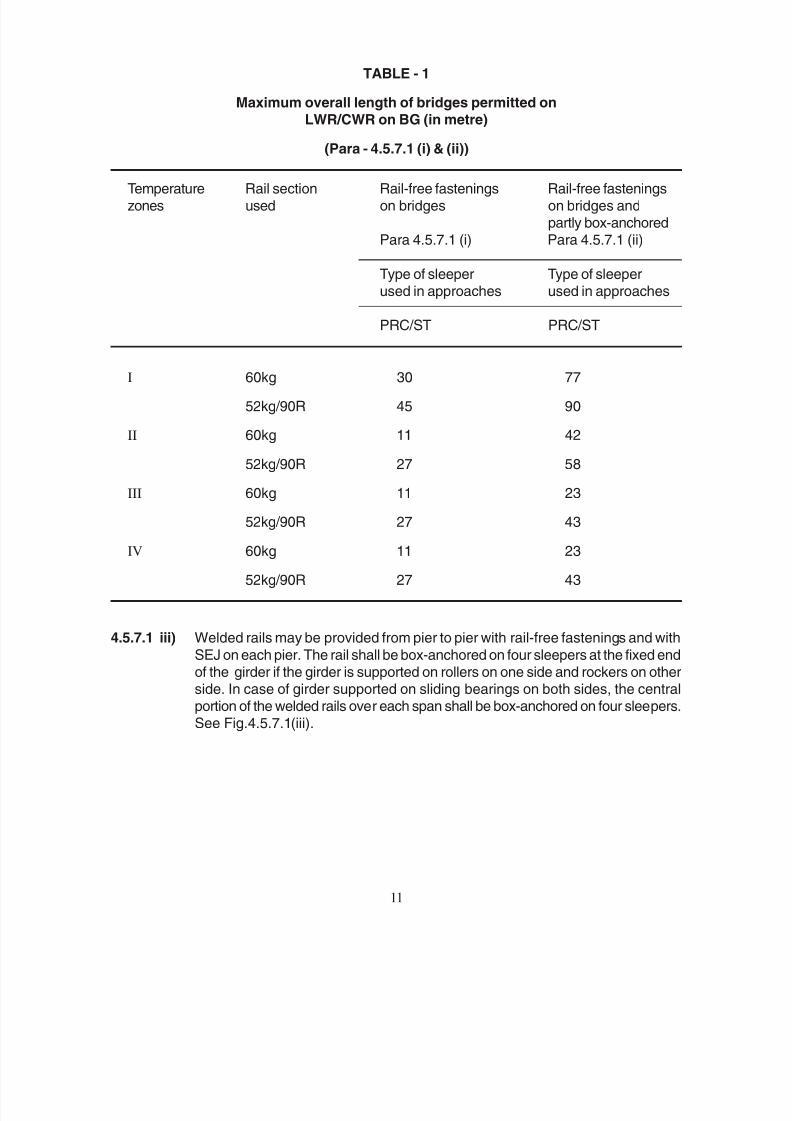
TABLE - 1
Maximum overall length of bridges permitted on
LWR/CWR on BG (in metre)
(Para - 4.5.7.1 (i) & (ii))
Temperature Rail section Rail-free fastenings Rail-free fasteningszones used on bridges on bridges and
partly box-anchoredPara 4.5.7.1 (i) Para 4.5.7.1 (ii)
Type of sleeper Type of sleeperused in approaches used in approaches
PRC/ST PRC/ST
I 60kg 30 77
52kg/90R 45 90
II 60kg 11 42
52kg/90R 27 58
III 60kg 11 23
52kg/90R 27 43IV 60kg 11 23
52kg/90R 27 43
4.5.7.1 iii) Welded rails may be provided from pier to pier with rail-free fastenings and with
SEJ on each pier. The rail shall be box-anchored on four sleepers at the fixed endof the girder if the girder is supported on rollers on one side and rockers on otherside. In case of girder supported on sliding bearings on both sides, the central
portion of the welded rails over each span shall be box-anchored on four sleepers.See Fig.4.5.7.1(iii).
11

8/20/2019 lwrm
http://slidepdf.com/reader/full/lwrm 36/226
4.5.7.1 iv) 4.5.7.1(iv) 120 190
9 9
IV 190 55 45 7.0 6.5
III 190 70 70 7.0 6.5
II 190 110 100 6.5 6.5
I 190 160 150 6.5 6.0
II 120 20 15 4.0 4.0
I 120 50 50 4.0 4.0
10
5.
5.1
12

8/20/2019 lwrm
http://slidepdf.com/reader/full/lwrm 37/226
4.5.7.1 iv) LWR/CWR may also be continued over a bridge with the provision of SEJ at thefar end approach of the bridge using rail-free fastenings over the girder bridge(Fig. 4.5.7.1 (iv)). The length of the bridge in this case, however, will be restrictedby the capacity of the SEJ to absorb expansion, contraction and creep, if any, ofthe rails. The length of the bridges with the above arrangement that can be permitted
in various rail temperature zones for LWR/CWR with SEJs having maximum
movement of 120 mm and 190 mm are as follows:-
Rail Max. Max. length of Initial gap to be
temp. move ment bridge with SEJ provided at td
zone of SEJ
used (mm)
With ST/PRC With CST-9 With ST/PRC With CST-9approach approach approach approach
sleepers sleepers sleepers sleepers
IV 190 55 m 45 m 7.0 cm 6.5 cm
III 190 70 m 70 m 7.0 cm 6.5 cm
II 190 110 m 100 m 6.5 cm 6.5 cm
I 190 160 m 150 m 6.5 cm 6.0 cm
II 120 20 m 15 m 4.0 cm 4.0 cm
I 120 50 m 50 m 4.0 cm 4.0 cm
Note: SEJ is to be installed 10 metre away from the abutments.
5. LAYING OF LONG WELDED RAILS AND CONTINUOUS WELDED RAILS
5.1 SURVEY
A foot by foot survey of the sections where LWR/CWR is proposed to be laid shallbe carried out in regard to the following:-
12
8/20/2019 lwrm
http://slidepdf.com/reader/full/lwrm 38/226
5.1.1
5.1.2
i)
ii)
iii)
iv)
v)
vi)
5.1.3 5.1.1 5.1.2 5.1.3 1:5000
5.2
5.2.1
2.2.1
5.2.2 1.7
5.3
i) 6.5
ii)
iii) 1 4.4.3 ( ), ( ) ( )
13

8/20/2019 lwrm
http://slidepdf.com/reader/full/lwrm 39/226
5.1.1 Locations over which LWR/CWR cannot be carried through on account ofconstraints such as bridges having substructure/superstructure in a distressedcondition, curves, gradients, points and crossings, unstable formation etc. shallbe identified. Such stretches of track shall be isolated from the remaining portionof LWR/CWR by provision of SEJs at either end.
5.1.2 Locations where following preliminary works are required to be carried out shallbe identified for completion before laying of LWR/CWR:-
i) Replacement of insulated joints by glued joints
ii) Realignment of curves
iii) Lifting or lowering of track to eliminate sags and humps
iv) Introduction and improvement of vertical curves
v) Stabilisation of troublesome formation
vi) Rehabilitation of weak bridges involving removal or lifting of rails orintroduction of temporary arrangements.
5.1.3 A detailed plan shall be made showing the exact locations of SEJs and of variousother features mentioned in sub-paras 5.1.1 & 5.1.2. A sample of the detailedplan may be seen at Fig. 5.1.3. The plans may be prepared to a horizontal scaleof 1:5000.
5.2 TEMPERATURE RECORDS
5.2.1 The maximum daily variation of rail temperature and the mean rail temperature
(tm) for the section shall be ascertained from the temperature records available
with the PWI-Incharge or as built up as per para 2.2.1.
5.2.2 If rail temperature records of preceding five years are not available, the mean andrange of rail temperatures shown in the ‘Map of India showing Rail TemperatureZones’ (Fig. 1.7), shall be adopted.
5.3 MATERIALS REQUIRED
Following materials are required for laying one LWR:-
i) Four numbers of 6.5 metre or longer rail pieces of the same rail section asLWR
ii) Two sets of SEJs with sleepers and fastenings
iii) Adequate numbers of 1 metre long fishplates with special screw clamps/ joggled fishplates with slotted grooves & bolted clamps as in Fig. 4.4.3 (a),(b) & (c)
13
8/20/2019 lwrm
http://slidepdf.com/reader/full/lwrm 40/226
5.3(iii)
iv)
v) 1 10
vi) 2 0.1 vii)
viii) 5.3 (viii) ( ) ( )
ix)
x)
xi)
5.4 5.4.1
4.2.1
5.1.2
5.4.2 5.8
5.5
5.5.1 10 20
5.5.2 880 90 -IV
5.5.3 5.6 6.5
14
8/20/2019 lwrm
http://slidepdf.com/reader/full/lwrm 41/226
Note: Slotted fishplates as in Fig. 5.3 (iii) with fish-bolts may be used in exceptional cases.
iv) Rail closures of suitable sizes
v) 1 metre and 10 cm straight edges
vi) Callipers and feeler gauges (2 mm to 0.1 mm)
vii) Rail cutting equipment
viii) Destressing equipment i.e. rollers, mechanical/hydraulic rail tensor, malletsand side rollers for curves, Fig. 5.3 (viii) (a) & (b)
ix) Alumino-thermic/mobile gas pressure welding equipment and consumablematerials
x) Equipment for protection of track
xi) Equipment for night working.
5.4 PRELIMINARY WORKS
5.4.1 Deep screening of ballast along with lifting or lowering of track, if required, shouldprecede laying of LWR/CWR. Standard ballast section as stipulated in para 4.2.1for LWR/CWR shall be provided.
All other preliminary works identified in para 5.1.2 shall also be completed beforelaying of LWR/CWR.
5.4.2 If any of the preliminary works can not be completed before installation of LWR/ CWR, such stretches should be isolated by providing SEJs. On completion ofthese works, such stretches may be welded, destressed and joined with LWR/ CWR in accordance with para 5.8.
5.5 WELDING OF RAILS TO FORM LWR
5.5.1 Rails shall normally be welded into sufficiently long panels of 10 to 20 rail lengths
or more by flash butt welding/gas pressure welding, either in the welding depot oron cess or in-situ. The joints in between only shall be welded by alumino-thermicwelding (SKV process).
5.5.2 While unloading 880 grade (90 UTS) or higher grade rails, handling instructionslaid down in Annexure-IV, should be followed.
5.5.3 Before laying long welded panels and/or before welding of rails, two complete
sets of SEJs, one at either end of the proposed LWR/CWR shall be inserted atpre-determined locations with gaps in mean position as per para 5.6. Closurerails of 6.5 metre or longer length shall be provided at LWR side/sides of SEJs tofacilitate adjustment of gaps during destressing operation.
14
8/20/2019 lwrm
http://slidepdf.com/reader/full/lwrm 42/226
5.5.4 1 5.7
200 100 9.1.2 (ii) 1.18
5.5.5 III 1 4.4.3( ) ( ) ( )
5.6
5.6.1 5.6
52 60 40
60
5.6.2 V 10
5.6.3
V 10
5.7
5.7.1 i) VI
ii) 30
15

8/20/2019 lwrm
http://slidepdf.com/reader/full/lwrm 43/226
5.5.4 Laying of welded panels and/or welding of joints at site can be done at any time ofthe year. But after welding into sufficiently long panels of about 1 km or longer,destressing as per para 5.7 shall be undertaken as soon as possible. Underunavoidable circumstances where destressing could not be done soon after andnot likely to be done within a reasonable period, a strict vigil shall be maintained
on the prevailing rail temperatures, and if the rail temperature rises more than
200C above the rail temperature at which welding of rails/laying of welded panelswas done, temporary destressing shall be undertaken at a rail temperature of100C below the maximum rail temperature likely to be attained until final destressing.If the rail temperature comes down appreciably, cold weather patrolling as perpara 9.1.2 (ii) should be introduced. Final destressing shall be done after
consolidation of track as per para 1.18 has been achieved.
5.5.5 Temporary speed restriction as indicated in Annexure-III shall be imposed on thelength of track where welded panels are joined by 1m long fishplates with specialscrew clamps or joggled fishplates with slotted grooves & bolted clamps as in
Fig. 4.4.3 (a) & (b) or (c).
5.6 GAPS AT SEJ
5.6.1 Gaps at SEJ shall be adjusted at the time of laying/subsequent destressing ofLWR/CWR, as illustrated in Fig. 5.6 and shall be as under:-
Rail section laid Gap to be provided at ‘td’
52kg/60kg 40 mm
Others 60 mm
5.6.2The gaps between the reference mark and tongue rail tip/stock rail corner at variousrail temperatures shall not differ by more than + 10 mm from the theoretical rangeas shown in Annexure-V.
5.6.3 Where fishplated or SWP track is joined on one side of SEJ, the gap between thereference mark and tongue rail tip/stock rail corner on LWR/CWR side shall notdiffer by more than +10 mm from the theoretical range as shown inAnnexure- V.
5.7 DESTRESSING OF LWR
5.7.1 Generali) The work of destressing shall be done during a traffic block under the personal
supervision of a PWI as laid down in Annexure-VI.
ii) It is preferable to impose a speed restriction of 30 km/h before actuallyobtaining the traffic block and to loosen/remove fastenings on alternatesleepers to reduce total duration of the traffic block.
15

8/20/2019 lwrm
http://slidepdf.com/reader/full/lwrm 44/226
5.7.2
i)
ii) 1
iii) 1.15
iv) 100
v)
x
50x
vi)
VII
vii)
16
8/20/2019 lwrm
http://slidepdf.com/reader/full/lwrm 45/226
5.7.2 Sequence of operations
The procedure to be adopted for destressing consists of the following steps:-
i) Remove impediments to free movement of rail such as rail anchors,guard rails, check rails etc.
ii) Create gap of about 1 metre at the centre of LWR during a traffic blockand insert a closure rail there at a restricted speed.
iii) Mark anchor lengths at either end of the proposed LWR in accordancewith para 1.15.
Notes: a) Anchor length shall be determined on the basis of the lowest value of t
p at which destressing is likely to be
carried out.
b) Anchor length shall be increased suitably if the
fastenings, rubber pads, liners or ballast conditions are poor.
iv) Erect marker pillars at the ends of anchor lengths on either side and at100 metre intervals thereafter.
v) Obtain a traffic block when tp is less than the desired installation
temperature (to), remove the closure rail at the centre and unfasten the
full length of rails leaving only the anchor lengths at either end. Mountthe rails on the rollers.
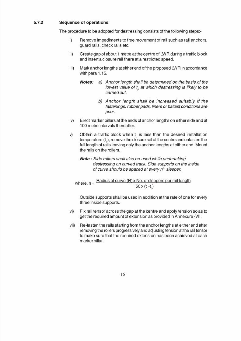
Note : Side rollers shall also be used while undertaking destressing on curved track. Side supports on the inside of curve should be spaced at every n th sleeper,
Outside supports shall be used in addition at the rate of one for everythree inside supports.
vi) Fix rail tensor across the gap at the centre and apply tension so as toget the required amount of extension as provided in Annexure -VII.
vii) Re-fasten the rails starting from the anchor lengths at either end afterremoving the rollers progressively and adjusting tension at the rail tensor
to make sure that the required extension has been achieved at eachmarker pillar.
16
where, n = Radius of curve (R) x No. of sleepers per rail length
50 x (to-t
p)

8/20/2019 lwrm
http://slidepdf.com/reader/full/lwrm 46/226
viii) 6.5 6.5 2 1 4.4.3 ( ) ( ) ( )
ix)
x)
xi)
5.7.3
i)
5.7.3 1
ii) 1
2
1
2
2
2
5.7.3 ( )
iii) 2
2
0
1
0 5.7.3 ( )
0
1 ,
1
2 100
100
iv)
5.7.3 ( )),
2
2
2
2
0
0
0
17
8/20/2019 lwrm
http://slidepdf.com/reader/full/lwrm 47/226
viii) Put paint marks on either side of the gap at the centre, spanning overthe gap at a distance of 6.5 metre. Insert a closure rail of a length equalto (6.5 metre - 2 gaps for welding + 1 mm for saw cut ends) and clampas per arrangements shown in Fig. 4.4.3 (a) & (b) or (c).
ix) Release and remove the rail tensor.
x) During another traffic block, weld both the joints of the closure rail atthe centre.
xi) Equalise stress at the centre and at the anchor lengths.
5.7.3 DESTRESSING OPERATION OF LWR WITH THE USE OF RAIL TENSORS
For destressing of LWR with the use of rail tensor, the following procedure shall beadopted:-
i) During the first traffic block, create a gap of 1 metre at location ‘B’ i.e.centre of LWR (Fig. 5.7.3). Introduce rail closure as required and fastenwith special fishplates and clamps. Allow traffic at restricted speed.
ii) Mark the anchor length A1 A
2 and C
1 C
2 each equal to l
a at either end of
the length A2 C
2 to be destresed (Fig. 5.7.3.(a)).
Note : The anchor length ‘l a ’ should be determined on the basis
of the lowest value of t p at which the destressing is likely to
be carried out.
iii) Erect marker pillars W0 W
1 etc., on each of the length A
2 B and C
2B.
Transfer the marks W0 onto the rail foot (Fig : 5.7.3(a)).
Note : The distances W 0 W
1, W
1 W
2 etc. shall be marked at about
100 metre intervals, the distance from the previous pillars and the last pillar W
B may be less than 100 metre.
iv) During the second traffic block, when tP is less than the desired t
o
(Fig. 5.7.3 (b)), destressing operation shall be carried out for the lengthsA
2 B and C
2 B as described below:-
a) Remove the closure rail from location ‘B.’ Unfasten and mount onrollers the portion from A
2 C
2.
b) Fix the rail tensor across the gap at ‘B’ and apply tension so asto obtain some movement at W
0 to remove any kinks or
misalignment and to minimise the friction in the rollers etc.Release the tension and note the movement Y
0 at W
0.
17
8/20/2019 lwrm
http://slidepdf.com/reader/full/lwrm 48/226
1
2
1
1
0
0
1
0 x x
2
2
1
1
2
1
0
1
2
2
1
2
i)
VII
x x
ii) 1
2
iii) 2 2
2
2
2
2
(6.5 2 x 25 1
18
8/20/2019 lwrm
http://slidepdf.com/reader/full/lwrm 49/226
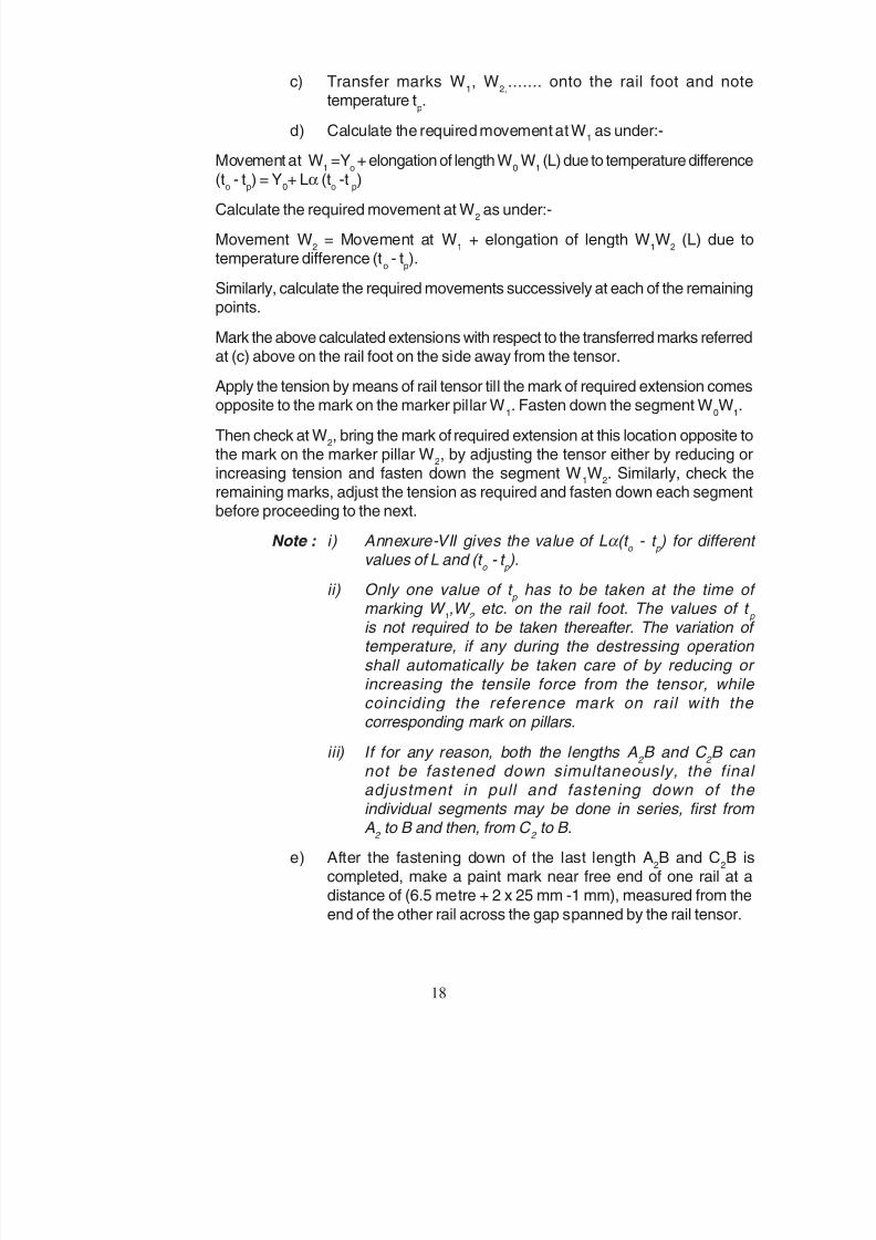
c) Transfer marks W1, W
2,....... onto the rail foot and note
temperature tp.
d) Calculate the required movement at W1 as under:-
Movement at W1 =Y
o + elongation of length W
0 W
1 (L) due to temperature difference
(to - t
p) = Y
0+ Lα (t
o -t
p)
Calculate the required movement at W2 as under:-
Movement W2 = Movement at W
1 + elongation of length W
1W
2 (L) due to
temperature difference (to - t
p).
Similarly, calculate the required movements successively at each of the remainingpoints.
Mark the above calculated extensions with respect to the transferred marks referredat (c) above on the rail foot on the side away from the tensor.
Apply the tension by means of rail tensor till the mark of required extension comesopposite to the mark on the marker pillar W
1. Fasten down the segment W
0W
1.
Then check at W2, bring the mark of required extension at this location opposite to
the mark on the marker pillar W2, by adjusting the tensor either by reducing or
increasing tension and fasten down the segment W1W
2. Similarly, check the
remaining marks, adjust the tension as required and fasten down each segmentbefore proceeding to the next.
Note : i) Annexure-VII gives the value of Lα (t o - t
p ) for different
values of L and (t o - t
p ).
ii) Only one value of t p has to be taken at the time of marking W
1,W
2 etc. on the rail foot. The values of t
p
is not required to be taken thereafter. The variation of temperature, if any during the destressing operation
shall automatically be taken care of by reducing or increasing the tensile force from the tensor, while coinciding the reference mark on rail with the corresponding mark on pillars.
iii) If for any reason, both the lengths A2 B and C
2 B can
not be fastened down simultaneously, the final adjustment in pull and fastening down of the individual segments may be done in series, first from A
2 to B and then, from C
2 to B.
e) After the fastening down of the last length A2B and C
2B is
completed, make a paint mark near free end of one rail at adistance of (6.5 metre + 2 x 25 mm -1 mm), measured from the
end of the other rail across the gap spanned by the rail tensor.
18
8/20/2019 lwrm
http://slidepdf.com/reader/full/lwrm 50/226
1 5.7.3 ( ))
v) 6.5
5.7.3 ( )) 25
25 5.7.3 ( )) 20
vi)
100 5.7.3 ( ))
vii)
1.11
100 5.6.1
5.7.4 1.11 VIII
5.8
5.8 ( ) ( )
i) 6.5
ii) 100
0
19

8/20/2019 lwrm
http://slidepdf.com/reader/full/lwrm 51/226
f) Remove the tensor, close the 1 metre gap temporarily and allowtraffic at restricted speed (Fig. 5.7.3 (c)).
v) During another traffic block, cut the rail at the paint mark, insert a rail closure
of length exactly equal to 6.5 metre and weld one end thereof (Fig. 5.7.3 (d)).If the gap at the other end is also 25 mm, it can be welded in the same block.
Otherwise, fasten with special fishplates and clamps and allow traffic atrestricted speed. In the latter case, during a subsequent block, when t
p is not
greater than to, release rail fastenings on either side to the required extent
and pull the rails with rail tensor to get the desired gap of 25 mm (Fig. 5.7.3
(e)); refasten the rail and weld the joint. Release the tensor after a lapse of aminimum of 20 minutes after pouring of the weld metal.
vi) During a subsequent traffic block, when tp is less than t
d, equalise the forces
in the rail by releasing the fastenings over a length of 100 metre on eitherside of location ‘B’ and tapping with wooden mallets etc. (Fig. 5.7.3 (f)).
Fasten down the rail and allow traffic.
vii) During another traffic block, when tp is within the range of temperature
specified for td in para 1.11, destress the end 100 metre from SEJ. Thereafter,
weld the closure rail next to SEJ duly ensuring setting of the SEJ as per para5.6.1.
5.7.4 In case rail temperature at the time of destressing is within the range specified inpara 1.11, detailed procedure as given in Annexure -VIII without using rail tensor,may be adopted.
5.8 JOINING LWRs INTO CWR
Detailed procedure for joining of LWRs into CWR is as given below ( Fig. 5.8 (a)to (f)):-
i) Replace the existing SEJs/buffer rails between the LWRs with ordinary rails,of which there should be two temporary rails about 6.5 metre long for each ofleft and right sides. Leaving the temporary rails fishplated, weld the otherrails.
Note: Where fluctuations of temperatures during the period of joining are likely to be small, only one temporary rail instead of two, may suffice.
ii) Provide W0 marker pillars for each of the LWRs at a distance of 100
metre from the centre of temporary rails, to mark the ends of the breathing
lengths.
19
8/20/2019 lwrm
http://slidepdf.com/reader/full/lwrm 52/226
iii) l
iv) 0
0 1 2
0
0
0'
0
0'
v)
5.8 ( )
vi) l + x x
0
0' 2 x 25 - 1
200 25 1 x x
VII
100 x x
23
vii) 5.8 ( )
viii) 5.8 ( ) l 25
25
ix) 5.8 ( ) 25
25 25 20
x) 5.8 ( )
20

8/20/2019 lwrm
http://slidepdf.com/reader/full/lwrm 53/226
iii) Keep ready two rails of standard length. Measure their lengths ‘l’ correct tothe nearest millimetre.
iv) Transfer the marks W0 to the rail flange for both the LWRs.
During the first traffic block when tp is less than desired t
0, remove the fish-
plates and fish-bolts connecting the temporary rails to the breathing lengths,release the fastenings of LWRs between the W
0 marks, mount the rails on
rollers and note the movements Y0 and Y'
0 at the marker pillars W
0, for LWRs
1 and 2 respectively.
Note : The movements of Y 0 and Y'
0 should be away from the ends of
LWR, if the LWRs are in a state of correct destressing.
v) Note tp and mark the anchor length on either side as shown Fig.5.8 (b).
vi) Make a paint mark near the end of either of the LWRs at a distance ofl + Lα(t
0-t
p) + Y
0 + Y'
0 + 2 x 25 -1 mm measured from the end of other LWR.
Here L = 200 metre, 25 mm is the allowance for each thermit weld and 1 mmis the allowance for a saw cut. The value of Lα(t
0-t
p) may be read from
Annexure-VII, e.g. for (t0 - t
p ) = 100C, Lα(t
0 - t
p) = 23 mm.
vii) Remove the rollers, fasten down the length ‘L’, introducing closure pieces, ifnecessary, and allow traffic (Fig. 5.8 (c)).
viii) During the second block (Fig. 5.8 (d)), cut the rail at the paint mark, removethe temporary rails, insert the rail of length ‘l’ and weld one end of it. If the gapat the other end is 25 mm, it can also be welded during the same block. If therequired 25 mm gap is not available, fasten the rails with fishplates and
clamps and allow traffic at restricted speed.
ix) During the third block (Fig. 5.8 (e)), weld the other joint if the gap is 25 mm.If the gap is more than 25 mm, release the rail fastenings on either side tothe required extent and pull the rails with rail tensor to get the desired gap of25 mm. Refasten and weld the rail. Release the tensor after the lapse of aminimum of 20 minutes after pouring of the weld metal.
x) During the fourth and final block (Fig. 5.8 (f)), equalise the forces in the railby releasing the fastenings over the portion marked ‘L’ and also over theanchor lengths on either side and tapping with wooden mallets, etc. Fasten
down the rail and restore traffic.
20
8/20/2019 lwrm
http://slidepdf.com/reader/full/lwrm 54/226
5.9
6.0
6.1 9.2.2
VI
6.2
i)
ii)
iii)
iv)
v)
vi)
6.2.1 i)
100
300
200 1.18
50 40 30 20
21
8/20/2019 lwrm
http://slidepdf.com/reader/full/lwrm 55/226
5.9 REFERENCE MARKS
Reference marks shall be fixed at each SEJ and at the centre of LWR/CWR, on
the reference pillars erected for this purpose. While the reference marks on thereference pillars shall be saw marks, corresponding marks on the running railsshall be paint marks on the non-gauge face of the rail. In no case, a saw mark shall
be made on the running rail. Reference marks are required to be fixed immediatelyafter destressing of LWR/CWR and shall not be shifted or tampered with thereafter.Additional reference marks in fixed portion and breathing length may be providedto know the behavior of LWR/CWR.
6.0 MAINTENANCE OF LWR/CWR
6.1 An important prerequisite for proper functioning of LWR/CWR is its initial laying toa high standard and its subsequent maintenance by trained personnel possessingvalid competency certificates as per para 9.2.2 and level of authorisation not lowerthan what is laid down in Annexure-VI.
6.2 REGULAR TRACK MAINTENANCE
Regular track maintenance in LWR/CWR includes following operations:-
i) Tamping/packing
ii) Lifting
iii) Aligning including minor realignment of curves
iv) Shallow screening/shoulder cleaning
v) Renewal of fastenings requiring lifting
vi) Maintenance of buffer rails
6.2.1 General
i) a) Track structure consisting of concrete sleepers in LWR/CWR
The regular track maintenance in LWR/CWR shall be confined to hourswhen rail temperature is between t
d
+10°C and td
-30°C and shall becompleted well before onset of summer. If rail temperature after main-tenance operation exceeds t
d+ 200C during the period of consolida-
tion as per para 1.18, the speed restriction of 50 km/h on BG and 40km/h on MG shall be imposed when shoulder and crib compaction hasbeen done and 30 km/h and 20 km/h respectively when shoulder and
crib compaction has not been done in addition to posting mobile watch-man.
21
8/20/2019 lwrm
http://slidepdf.com/reader/full/lwrm 56/226
100
300
200 1.18 50
40
ii)
600 350 100 75
iii)
iv) 224 ( ) (ii)
v)
vi) 1411
vii) 6.2.2
i)
50 25
6.2.1(i)
22
8/20/2019 lwrm
http://slidepdf.com/reader/full/lwrm 57/226
b) Track structure consisting of sleepers other than concrete sleepers
The regular track maintenance in LWR/CWR shall be confined to hours
when the rail temperature is between td+10°C and t
d-30°C and shall be
completed well before onset of summer. If rail temperature after themaintenance operation exceeds t
d+20°C during the period of consoli-
dation as per para 1.18, then the speed restriction of 50 km/h on BGand 40 km/h on MG shall be imposed.
ii) Ballast section shall be properly maintained, specially on pedestrian & cattlecrossings, curves and approaches to level crossings and bridges. Cess levelshould be correctly maintained. Dwarf walls may be provided on pedestrianand cattle crossings to prevent loss of ballast. Replenishment of ballast shallbe completed before onset of summer. Shortage of ballast in the shoulder atisolated places shall be made up by the Gangmate by taking out minimum
quantity of ballast from the centre of the track between the two rails over awidth not exceeding 600 mm/350 mm and a depth not exceeding 100 mm/
75 mm for BG/MG respectively.
iii) Sufficient quantity of ballast shall be collected to provide full ballast sectionbefore commencing any maintenance operation, specially lifting.
iv) When crow bars are used for slewing, care shall be taken to apply these in amanner so as to avoid lifting of track. In this connection, the instructions in
para 224(d) (ii) of IRPWM shall be followed.
v) Special attention shall be paid to maintenance of track at following locations:
- SEJs/breathing lengths- Approaches of level crossings, points & crossings and unballasted
deck bridges
- Horizontal and vertical curves
vi) Special attention shall be paid to maintenance of fastenings in LWR/CWRespecially on concrete sleepers according to para 1411 of IRPWM .
vii) All fastenings shall be complete and well secured.
6.2.2 Mechanised Maintenance
i) Maintenance tamping:
Tamping in LWR/CWR with general lift not exceeding 50 mm in case of
concrete sleeper and 25 mm in case of other sleepers including correctionof alignment shall be carried out during the period when prevailing railtemperatures are as per para 6.2.1 (i) together with precautions laid downtherein.
22

8/20/2019 lwrm
http://slidepdf.com/reader/full/lwrm 58/226
ii)
50 25 1.18
iii)
6.2.1(i)
6.2.3
i) 30 30
10
24 2
ii)
iii) 30
-300
+100 100
6.2.4
30 6.2.1(i)
6.2.5
6.2.1(i)
23
8/20/2019 lwrm
http://slidepdf.com/reader/full/lwrm 59/226
ii) Lifting of track:
Lifting where needed, in excess of 50 mm in case of concrete sleepers/
25 mm in case of other types of sleepers shall be carried out in stages withadequate time gap in between successive stages such that full consolidationof the previous stage as per para 1.18 is achieved prior to taking up the
subsequent lift.
iii) Cleaning of shoulder ballast:
Mechanised cleaning of shoulder ballast shall be undertaken when prevailingrail temperatures are within the limits prescribed in para 6.2.1(i) together
with the precautions mentioned therein.
6.2.3 Manual maintenance
i) At no time, not more than 30 sleepers spaces in a continuous stretch shallbe opened for manual maintenance or shallow screening with atleast 30 fully
boxed sleeper spaces left in between adjacent openings. Maintenance of inbetween lengths shall not be undertaken till passage of traffic for atleast 24hours in case of BG carrying more than 10 GMT or 2 days in case of otherBG and MG routes.
ii) For correction of alignment, the shoulder ballast shall be opened out to theminimum extent necessary and that too, just opposite the sleeper end. Theballast in shoulders shall then be put back before opening out crib ballast for
packing.
iii) In exceptional circumstances when more than 30 sleeper spaces have to
be opened for any specific work, like through screening of ballast etc. duringthe period of the year when minimum daily rail temperature is not below
td-30°C or maximum does not go beyond t
d+10°C, upto 100 sleeper spaces
may be opened under the direct supervision of PWI. It should however,be ensured that rail to sleeper fastenings on the entire length of LWRare functioning satisfactorily and SEJs do not indicate any unusual behaviour.
6.2.4 Casual renewal of sleepers
Not more than one sleeper in 30 consecutive sleepers shall be replaced at a time.
Should it be necessary to renew two or more consecutive sleepers in the same
length, they may be renewed one at a time after packing the sleepers renewedearlier duly observing the temperature limits specified in para 6.2.1(i) togetherwith precautions mentioned therein.
6.2.5 Renewal of fastenings
The work of renewal of fastenings shall be carried out when rail temperature iswithin the limits specified in para 6.2.1 (i) with following additional precautions:-
23

8/20/2019 lwrm
http://slidepdf.com/reader/full/lwrm 60/226
i)
15
ii)
30
6.2.6
i) 15
6.4
ii)
iii) -IX
6.2.7
7.2
6.3
i)
ii)
iii)
iv)
v)
vi)
24

8/20/2019 lwrm
http://slidepdf.com/reader/full/lwrm 61/226
i) Renewal of fastenings not requiring lifting:
Fastenings not requiring lifting of rails, shall be renewed on not more
than one sleeper at a time. In case fastenings of more than one sleepersare required to be renewed at a time, then atleast 15 sleepers inbetween shall be kept intact. Work shall be done under supervision of
Keyman.
ii) Renewal of fastenings requiring lifting:
Fastenings requiring lifting of rails i.e. grooved rubber pads, etc. shallbe renewed on not more than one sleeper at a time. In case fastenings
of more than one sleepers are required to be renewed at a time, thenatleast 30 sleepers in between shall be kept intact. Work shall de doneunder supervision of Gangmate.
6.2.6 Maintenance of SEJs/buffer rails
i) Once in a fortnight SEJs shall be checked, packed and aligned if necessary.Oiling and greasing of tongue and stock rails of SEJ and tightening offastenings shall be done simultaneously. Movement of SEJs shall be checkedand action taken for destressing if necessary as per para 6.4.
ii) During his daily patrolling, Keyman shall keep special watch on the SEJsfalling in his beat.
iii) Buffer rails shall be maintained in accordance with Annexure-IX.
6.2.7 Renewal of defective rails/welds
The procedure laid down in para 7.2 of this manual for repairs to track after railfracture shall be followed.
6.3 SPECIAL TRACK MAINTENANCE
Special track maintenance in LWR/CWR includes following operations:-
i) Through fittings renewal
ii) Deep screening/mechanised cleaning of ballast
iii) Lowering/Lifting of track
iv) Major realignment of curves
v) Sleeper renewal other than casual renewals
vi) Rehabilitation of bridges and formation causing disturbance to track
24

8/20/2019 lwrm
http://slidepdf.com/reader/full/lwrm 62/226
6.3.1
6.3.2
i) 238 (2) ( )
ii)
iii)
100
- 200
100 1 6.5
4.4.3 ( ) ( ) ( )
iv)
100
15
25

8/20/2019 lwrm
http://slidepdf.com/reader/full/lwrm 63/226
6.3.1 Through fittings renewal
Whenever it is decided to carry out through renewal of fittings so as to ensure
proper functioning of LWR, the LWR shall be destressed alongwith the throughfittings renewal.
6.3.2 Deep screening/mechanised cleaning of ballast
i) Provisions laid down in para 238 of IRPWM will also apply mutatis- mutandisto LWR/CWR with further provisions as mentioned hereafter in this para.Wherever mechanised cleaning of ballast is resorted, the detailed procedurelaid down in para 238 (2) (e) of IRPWM for manual deep screening shall
stand replaced by the sequence of operations of Ballast Cleaning Machine(BCM).
ii) Ballast Cleaning Machine (BCM), tamping machine and Dynamic TrackStabilizer (DTS) shall, as far as possible, be deployed in one consist.
iii) Temperature records of the sections where deep screening is to beundertaken, shall be studied for the previous and the current year. Themaximum and minimum rail temperature attainable during the period of deepscreening and during the period of consolidation shall be estimated. Any of
the following three methods may be adopted for carrying out the work ofdeep screening/mechanised cleaning:-
a) If range of rail temperature falls within td+10OC to t
d-20OC, deep
screening may be done without cutting or temporary destressing.
b) If range of rail temperature falls outside (a) above, temporary
destressing shall be carried out 10OC below the maximum railtemperature likely to be attained during the period of work. CWR shall
be cut into LWRs of about 1 km length with two temporary buffer rails of6.5 metre long clamped as per arrangements shown in Fig. 4.4.3 (a) &(b) or (c).
c) Wherever rail renewals are being carried out, LWR/CWR may be
converted into three rail panels and deep screening done.
iv) Constant monitoring of rail temperature shall be done during the progress of
work. Should the temperature rise more than 10OC above td /temporary
destressing temperature, adequate precautions shall be taken includinganother round of temporary destressing.
Note : Deep screening shall be undertaken within 15 days of temporary
destressing failing which temporary destressing may become due again, if the rail temperature varies appreciably.
25

8/20/2019 lwrm
http://slidepdf.com/reader/full/lwrm 64/226
v)
300 9.1.2(ii)
vi)
1.18 5.7
6.3.3
i)
ii) 6.3.1(iii) (iv)
iii) 5.8
6.4
6.4.1 5.7
i)
5.6.2 5.6.3
ii) 6.3
iii) 7.1
iv) 1
26

8/20/2019 lwrm
http://slidepdf.com/reader/full/lwrm 65/226
v) During the period of deep screening, if there is any possibility of minimumtemperature falling 30OC below t
d /temporary destressing temperature, cold
weather patrol as per para 9.1.2 (ii) should be introduced to detect/ guardagainst rail fractures.
vi) Sequence of operation: -
a) Deep screening of LWR may be done from one end of LWR to other
end.
b) After deep screening and consolidation as per para 1.18, destressingof LWR shall be undertaken as per para 5.7.
6.3.3 Other special maintenance
i) Other types of special track maintenance constitute jobs like lowering oftrack, major realignment of curves, renewal of large number of sleepers orrehabilitation of formation/ bridges causing disturbance to track. For carrying
out such maintenance, the affected length of track may be isolated from LWR/ CWR by introducing SEJs or buffer rails as needed.
ii) Temperature records of the section shall be studied and action taken inaccordance with para 6.3.1(iii) & (iv).
iii) After completion of work, the affected length of track shall be destressed atthe required destressing temperature and joined with rest of the LWR/CWRin accordance with para 5.8.
6.4 DESTRESSING DURING MAINTENANCE
6.4.1 Abnormal behavior of LWR/CWR whenever gets manifested in one or more of thefollowing, destressing shall be undertaken as per procedure laid down in para5.7:-
i) When the gap observed at SEJ
a) differs beyond limits specified in para 5.6.2 & 5.6.3
b) exceeds the maximum designed gap of SEJ
c) when stock/tongue rail crosses the mean position.
ii) After special maintenance operations mentioned in para 6.3
iii) After restoration of track following an unusual occurence mentioned in para7.1
iv) If number of locations where temporary repairs have been done exceed threeper km.
26
8/20/2019 lwrm
http://slidepdf.com/reader/full/lwrm 66/226
6.4.2 1 5.8
6.5
6.5.1
i) 4.4.3 ( )
ii)
iii) 4.4.3 ( ) ( )
iv)
6.5.2
5.3
7.
7.1
i)
ii)
iii) iv)
7.2.
7.2.1
i) 1 4.4.3 ( ) ( ) ( )
ii) 1
iii)
iv)
v) 6.5
27
8/20/2019 lwrm
http://slidepdf.com/reader/full/lwrm 67/226
6.4.2 Destressing of CWR shall be done by cutting it into LWRs of about 1 km lengthwhich shall be joined after destressing in accordance with para 5.8.
6.5 SPECIAL EQUIPMENT FOR MAINTENANCE OF LWR/CWR
Staff responsible for maintenance of LWR/CWR shall be trained in using andequipped with additional equipment detailed below:-
6.5.1 Additional equipment with the Gangs
i) A pair of joggled fishplates with bolted clamps (Fig. 4.4.3 (c))
ii) Rail thermometer with markings for temperature ranges for maintenance
iii) Special 1 metre long fishplates with screw clamps (Fig. 4.4.3 (a) & (b))
iv) Rail closure pieces.
6.5.2 Additional equipment with PWI
Equipments as listed in para 5.3 shall be available with PWI.
7. UNUSUAL OCCURRENCES
7.1 LIST OF UNUSUAL OCCURRENCES
Unusual occurrences in LWR/CWR comprise of the following:-
i) Rail fractures or replacement of defective rail/ glued joint
ii) Damage to SEJ/buffer rails
iii) Buckling or tendency towards buckling
iv) Factors causing disturbance to LWR/CWR such as accidents,
breaches etc.
7.2 RECTIFICATION OF RAIL FRACTURES
7.2.1 Equipment required
i) Special 1 metre long fishplates with screw clamps and joggled
fishplates with bolted clamps (for fractures at welded joints) as per
arrangement shown in Fig. 4.4.3 (a) & (b) or (c)
ii) Steel tape capable of reading upto one mm
iii) Alumino-thermic welding and finishing equipment
iv) Equipment for destressing
v) 6.5 metre long sawn rail cut piece of the same section as LWR dulytested by USFD
27
8/20/2019 lwrm
http://slidepdf.com/reader/full/lwrm 68/226
vi)
vii)
viii)
7.2.2
7.2.3
4.4.3 ( ) ( ) ( ) 30 10
20
7.2.4
4 4.4.3 ( ) ( ) ( )
i) 1.11
ii) 4 51 7.2.4
4 7.2.4
28

8/20/2019 lwrm
http://slidepdf.com/reader/full/lwrm 69/226
vi) Rail closures of suitable lengths
vii) Equipment for protection of track
viii) Equipment for night working
7.2.2 Procedure for repairs
If any fracture takes place on LWR/CWR, immediate action shall be taken by theofficial who detected the fracture to suspend the traffic and to protect the line. He
shall report the fracture to the Gangmate/Keyman/PWI, who shall arrange formaking emergency repairs to pass the traffic immediately. Repairs shall be carriedout in four stages as described below:-
a) Emergency repairs to pass the traffic immediately
b) Temporary repairs
c) Permanent repairsd) Destressing.
7.2.3 Emergency repairs
The fractured rails shall be joined by using the arrangements shown in Fig. 4.4.3(a) & (b) or (c). If the gap at fracture does not exceed 30 mm, insertion of anyclosure rail piece is not necessary. The traffic may then be resumed at a speed ofstop dead and 10 km/h for the first train and 20 km/h for subsequent trains.
7.2.4 Temporary repairs
If a welding party is not readily available, the fracture shall be repaired by using acut rail (not less than 4 metre long) and clamped/bolted as per arrangement shown
in Fig. 4.4.3 (a) & (b) or (c).
i) A traffic block shall be taken as soon as possible preferably when therail temperature is within the range specified for t
d in para 1.11.
ii) a) Two points on either side of the fracture shall be marked on the railsuch that the length of closure rail (not less than 4 metre) to be insertedis equal to the total length of the rail pieces removed from the track
minus allowances for two welds and saw cut (normally 51 mm). SeeFig. 7.2.4.
b) Alternately two points on either side of the fracture shall be marked onthe rail at a distance equal to the length of the available closure rail.The length of closure rail should not become less than 4 metre at the
time of permanent repairs. See Fig. 7.2.4.
28
8/20/2019 lwrm
http://slidepdf.com/reader/full/lwrm 70/226
iii) 7.2.3 III (ii)
7.2.5
i)
ii) 7.2.4(ii)
iii) 7.2.4(ii) 50 7.2.5 (ii)
iv) 125
7.3
7.3.1 5.6.1
7.3.2
III
29

8/20/2019 lwrm
http://slidepdf.com/reader/full/lwrm 71/226
iii) The rails shall then be cut through at these points simultaneously,if possible. The closure rail shall then be inserted and joined asper para 7.2.3. After joining, the traffic shall then be resumed atrestricted speed in accordance with Annexure-III. In case closurerail as per para (ii) (a) above is inserted, one of the joints may have to
be provided with closure piece of adequate width and joined by one
metre fishplate and clamps.
7.2.5 Permanent Repairs
i) If the fracture is such that, wide gap AT welding can be adopted,then the total length of fractured ends to be cut shall be equal tothe gap required for wide gap welding. Once the two ends are cut,a gap required for wide gap welding will be created by using railtensors and joint welded by wide gap AT welding technique.
ii) In case rail closure as per para 7.2.4(ii)(a) has been provided fortemporary repairs, one joint of the closure rail shall be welded withoutrail tensor after setting correct gap for welding. However, to ensurecorrect gap during welding of the other joint, tensor shall be used.
iii) In case rail closure as per para 7.2.4(ii)(b) has been provided at thetime of temporary repairs, the rail closure shall be suitably cut such thatthe length of the rail to be finally inserted in track is equal to length ofrail removed from track after fracture minus allowances for two weldsi.e. 50 mm. Once the closure rail is cut, the closure rail will be weldedas given in para 7.2.5 (ii).
iv) After welding of joints, a length of track equal to breathing length orabout 125 metres on either side be unfastened and tapped to ensureequalisation of stress and then refastened.
7.3 DAMAGE TO SWITCH EXPANSION JOINT
7.3.1 The damaged/broken SEJ shall be replaced. The new SEJ shall be adjusted asper para 5.6.1. Traffic may be allowed if necessary at a restricted speed and
thereafter restriction relaxed progressively.
7.3.2 If another SEJ is not available for replacement, both the damaged SEJ and theundamaged SEJ on the opposite rail at the same location, shall be replaced by aclosure rail and connected to LWR/CWR with special clamps and fishplates. The
traffic over the clamped joints may be permitted at a restricted speed as perAnnexure-III. The restriction may be relaxed only after the new SEJ has beeninserted in the correct position and the clamped joint has been replaced with in-situ weld.
29

8/20/2019 lwrm
http://slidepdf.com/reader/full/lwrm 72/226
7.4
7.4.1
i)
ii)
iii)
iv)
v)
7.4.2
i)
ii)
iii)
7.4.3
i)
ii)
30

8/20/2019 lwrm
http://slidepdf.com/reader/full/lwrm 73/226
7.4 BUCKLING OF TRACK
7.4.1 General
Buckling or a tendency towards buckling may occur, among others, in the followingcircumstances:-
i) Failure to adhere to the temperature ranges specified for operation onLWR/CWR
ii) Inadequate resistance to longitudinal, lateral and vertical movement oftrack due to deficiencies in ballast section or/and inadequate ballastconsolidation
iii) Use of ineffective fastenings or missing fastenings resulting in loss ofcreep resistance and torsional resistance
iv) Excessive settlement of formation
v) Improper functioning of SEJ.
7.4.2 Buckling and its investigation
i) Tendency towards buckling will usually manifest itself through kinks in track.Kinks may also arise from incorrect slewing or lifting operations. By tapping
sleepers for hollowness, it may be possible to notice if there is any tendencytowards vertical buckling.
ii) As soon as the tendency for buckling is detected, the traffic shall besuspended and the track protected. The track shall then be stabilised byheaping ballast on the shoulders upto the top of the web of the rail obtaining
the ballast from inter-sleeper spaces between the rails. Thereafter fullinvestigation shall be made to find out the cause of the tendency for buckling.
iii) Each case or buckling shall be investigated by AEN soon after its occurrenceand a detailed report submitted to DEN/Sr. DEN.
7.4.3 Repairs to buckled track
i) When the track actually buckles, the traffic shall be suspended and the cause
of buckling ascertained. The position of tongue and stock rails of the SEJshall be checked. The methods for rectification are explained below.
ii) The rectification shall normally be carried out in the following stages underthe supervision of PWI:-
a) Emergency repairs
b) Permanent repairs
c) Destressing.
30
8/20/2019 lwrm
http://slidepdf.com/reader/full/lwrm 74/226
7.4.4
6.5
III
7.4.5
i) 7.2.4 7.2.5
ii)
5.7
7.5
7.5.1 1.11
7.5.2
7.5.3
7.5.4
8.
8.1
8.1.1 4.2.1( ) ( )
8.1.2
31
8/20/2019 lwrm
http://slidepdf.com/reader/full/lwrm 75/226
7.4.4 Emergency repairs
The buckled rails shall preferably be gas cut adequately apart not less than 6.5
metre. The track shall then be slewed to the correct alignment and cut rails of therequired lengths shall be inserted to close the gaps making due provision forwelding of joints on both sides. The cut rails shall then be connected by use of
special fishplates and screw clamps and the line opened to traffic with speedrestriction as indicated in Annexure-III.
7.4.5 Permanent repairs
i) As soon as possible the clamped joints shall be welded adopting the same
procedure as in paras 7.2.4 and 7.2.5. Additional pair of cut rails and railcutting equipment shall also be required to adjust the gaps in case they havebeen disturbed in the intervening period. The speed restriction shall beremoved after welding.
ii) The entire panel shall be destressed as soon as possible as per para 5.7.
7.5 BREACHES, TEMPORARY GIRDERS AND DIVERSIONS
7.5.1 The affected portion shall be isolated by insertion of SEJs preferably within thetemperature range specified for t
d in clause 1.11. The track thus isolated shall be
replaced by fishplated track which shall be box anchored, if necessary.
7.5.2 In the breached sections where the new banks are constructed, the formation shallbe fully consolidated before laying LWR/CWR again.
7.5.3 In case of diversions and insertion of temporary girders, SEJ shall be inserted to
isolate the portion where such work is required to be done.
7.5.4 LWR/CWR panels in the affected portion shall be destressed immediately afterthe LWR/CWR are restored.
8. INSPECTION AND RECORDS
8.1 INSPECTION:- While requiring less maintenance, LWR/CWR necessitateintensive inspection at supervisory and officer’s level.
8.1.1 The profile of the ballast section shall always be as shown in Fig 4.2.1(a) to (d).
This should be checked, specially at pedestrian/cattle crossings, curves,approaches of level crossings, points and crossings and bridges. Cess level shouldbe correctly maintained. Replenishment of ballast shall be completed before theonset of summer.
8.1.2 Inspection shall be more frequent in the afternoons during summer months. Duringinspections, look out shall be kept for kinks, incipient buckles and checks madeon functioning of the patrols.
31
8/20/2019 lwrm
http://slidepdf.com/reader/full/lwrm 76/226
8.1.3
8.1.4
8.1.5
i)
ii)
8.2
8.2.1 XI, XII XIII XIII
8.2.2 212 (4)
8.2.3 XIII XIII
8.2.4 20
8.2.5
32
8/20/2019 lwrm
http://slidepdf.com/reader/full/lwrm 77/226
8.1.3 Knowledge of staff in regard to prescribed maintenance practices shall beperiodically checked and it shall be ensured that the work is done accordingly.
8.1.4 Ultrasonic examination of rails should not be in arrears. Defective rails/welds should
be replaced expeditiously.
8.1.5 Inspections of gaps at SEJ and creep/movement at centre of LWR/CWR byPermanent Way officials would be done as per following schedule:-
i) PWI-Incharge/PWI Sub-section:-
a) Every fortnight during the two coldest and two hottest months of theyear at about minimum and maximum temperatures alternately by PWI
Incharge and PWI Sub-section.
b) Alternately once in two months during other months of the year.
ii) Assistant Engineer:-
At least once in six months, preferably during coldest andhottest months.
8.2 RECORDS
8.2.1 Record of LWR/CWR, as per the proforma laid down in Annexures-XI, XII, XIII A,and XIII B, shall be maintained by the PWI in a permanent register called the
Sectional LWR/CWR Register. The PWI shall be responsible for keeping thisregister up-to-date.
8.2.2 An indication plate similar to that suggested in para 212(4) of Indian RailwaysPermanent Way Manual shall be fixed on the cess at each SEJ showing the dateof destressing, destressing temperature t
d / t
o and length of LWR/CWR.
8.2.3 Observations of gaps at SEJ and creep/movement in fixed portion of LWR/CWRshall be recorded by the PWI/AEN as per Annexure-XIII A and XIII B.
8.2.4 When creep in fixed portion of LWR/CWR exceeds 20 mm, full investigation shallbe carried out and remedial measures undertaken.
8.2.5 AEN will analyse the observation of each LWR/CWR in his jurisdiction and give acertificate at the end of LWR/CWR register before onset of summer regarding
satisfactory behavior of all LWR/CWRs. DEN/Sr.DEN will scrutinise observationsof each LWR/CWR, initial each page and send exception report to Territorial ChiefEngineer for his decision/orders.
32
8/20/2019 lwrm
http://slidepdf.com/reader/full/lwrm 78/226
9.
9.1
9.1.1
i) 6.2.6
ii) 6.2.1(iii)
iii)
iv)
v)
9.1.2
i)
X
ii)
X
33

8/20/2019 lwrm
http://slidepdf.com/reader/full/lwrm 79/226
9. DUTIES, RESPONSIBILITIES & TRAINING OF STAFF
9.1 DUTIES AND RESPONSIBILITIES:- The following are the special duties and
responsibilities with reference to LWR/CWR:-
9.1.1 Keyman
i) He shall carry out fortnightly oiling and greasing of SEJ, checking andre-tightening of fastenings at SEJ and other sleepers, if necessary (Para6.2.6).
ii) He shall replace missing fastenings not requiring lifting or slewing oftrack as per para 6.2.1(iii) and tighten the loose fittings.
iii) He shall ensure that all creep anchors, where provided, butt against
the sleepers and in case of large scale displacement of anchors, shallreport the matter to Gangmate/PWM/PWI.
iv) He shall watch for unusual features and on noticing any bucklingtendency or damage to track, shall take necessary action to protectthe track and report the same immediately to nearest Station Master/ PWI.
v) He shall keep a sharp look out on winter mornings for any rail fractures.
On noticing a rail fracture, he shall take prompt action to protect trackand carry out emergency repairs to permit the restoration of trafficpromptly and report to nearest Station Master/PWI.
9.1.2 Patrolman & Watchman
i) Hot Weather Patrolman:
He shall patrol the track during the hottest part of the day, to look for prominentkinks, incipient buckles or tendency towards bucklings. He shall protect thetrack at the site of the prominent kinks, incipient or actual buckles and reportthe same to nearest Station Master and PWI immediately. Detailedinstructions for carrying out hot weather patrols as given in Annexure-X Ashall be followed.
ii) Cold Weather Patrolman:
He shall patrol the track during the coldest part of the night and lookout forweld/rail fractures and excessive gaps at SEJ. He shall protect the track atthe site of weld/rail fractures or excessive gaps at SEJ and report the sameto nearest Station Master/PWI. Detailed instructions for carrying out coldweather patrols as given in Annexure-X B shall be followed.
33
8/20/2019 lwrm
http://slidepdf.com/reader/full/lwrm 80/226
iii)
1.18
+200
X
9.1.3 i)
ii) -VI
iii)
iv)
+200
v)
vi) 157 806
vii)
+ 200
34
8/20/2019 lwrm
http://slidepdf.com/reader/full/lwrm 81/226
iii) Mobile Watchman:
a) He shall be posted, till period of consolidation is over, on stretches
where after maintenance operation, rail temperature has exceeded td
+ 20OC during the period of consolidation as given in para 1.18.
b) The mobile watchman would patrol such section/beat to look forprominent kinks, incipient buckles or tendency towards buckling, rail/
weld fracture and excessive gaps at SEJs.
c) He shall protect the track at site if any of the situations as given in(b) above occurs and report the same to nearest Station Master/
PWI.
Detailed instructions for the works to be carried out by mobile watchman are givenin Annexure-X C.
9.1.3 Gangmate/Permanent Way Mistry (PWM)
i) They shall carry out maintenance work under their personal supervision onlyif they are in possession of valid competency certificate issued by Zonal/ Divisional Training Centre to work on LWR/CWR section.
ii) They shall undertake only those works of track maintenance for which they
are authorised as per Annexure-VI.
iii) They shall maintain additional/special equipment issued to them in goodcondition and bring to the notice of PWI defective equipment requiringrepairs.
iv) They shall ensure that hot weather patrolmen turn out on duty duringthe specified patrol period and carry out the patrolling duties correctly.They shall be vigilant during hot weather and order patrol if the
temperature is likely to reach td+20OC and report to their supervisors
any unusual occurrences which take place on the LWR/CWR in theirbeat.
v) They shall take prompt action to protect the track in case of rail/weld fractures
and carry out emergency repairs to permit the restoration of traffic promptlyand report to nearest Station Master/PWI.
vi) They shall take immediate steps to secure the safety of the trains as perpara 157 and 806 of IRPWM, if they consider that track is likely to be rendered
unsafe.
vii) They shall impose the specified speed restriction and post watchman if
the temperature exceeds td + 20OC during the period of consolidation after
the maintenance work had been completed.
34

8/20/2019 lwrm
http://slidepdf.com/reader/full/lwrm 82/226
viii)
ix)
x)
xi)
9.1.4
i)
ii) -VI
iii)
8.1.5 -XI, XII, XIII XIII
35
8/20/2019 lwrm
http://slidepdf.com/reader/full/lwrm 83/226
viii) They shall make up the shortage of ballast at isolated vulnerable locationsand report any ballast deficiency or disturbance of track to the PWI.
ix) They shall inspect SEJ and LWR/CWR under their jurisdiction frequently,specially during the hottest part of the afternoons in summer andreport any unusual occurrence on LWR/CWR to PWI and obtain his
order.
x) They shall ensure that men working under them have knowledge of workingon LWR/CWR.
xi) They shall introduce cold weather patrolling when instructed by their
Supervisors.
9.1.4 Permanent Way Inspector (Incharge of Section/Sub-section)
i) They shall be in possession of Manual of Instructions on LWR/ CWR posted up-to-date at all times. They shall have a thorough knowledge
of important pre-requisites for proper functioning of LWR/CWR and thelimitations and precautions laid down for work on LWR/CWR. They shallensure that the maintenance instructions are strictly followed by all the staffunder him dealing with maintenance of LWR/CWR.
ii) They shall supervise all track maintenance work for which they areresponsible as per Annexure-VI.
iii) They shall be responsible:-
a) For inspection of gaps at SEJ and creep/movement at centre of LWR/
CWR as per para 8.1.5 and recording observations of each LWR/CWRas per Annexure- XI, XII, XIII A and XIII B in a register.
b) For making arrangements for patrolling of track in hot and cold weather
and post mobile watchmen as and when required. They will ensurethat patrolmen and mobile watchmen are issued proper equipmentsfor carrying out patrolling.
c) For repairs and restoration of traffic in case of accident, derailment,
buckling, washaways, rail fracture etc.
d) For carrying out destressing, welding and other maintenance operationcorrectly and complete them within the block period for which blockhas been taken.
35
8/20/2019 lwrm
http://slidepdf.com/reader/full/lwrm 84/226
iv)
v)
vi) 1
vii)
viii)
ix)
+200
x)
9.1.5 9.1.4
i)
ii) XI, XII, XIII XIII
9.1.6
9.1.4 9.1.5
36

8/20/2019 lwrm
http://slidepdf.com/reader/full/lwrm 85/226
iv) They shall inspect LWR/CWR under their jurisdiction frequently, especiallyduring the hottest part of afternoons in summer to lookout for unusual features, tendency towards buckling and checkpatrolling.
v) They shall ensure that all maintenance staff under them are fully aware oftheir duties and responsibilities at all time with regard to maintenance ofLWR/CWR.
vi) They shall always carry during their inspection a pair of joggled fishplates,clamps, rail thermometer, feeler gauges and one meter straight edge.
vii) They shall record rail temperatures, destressing temperature, minimum andmaximum rail temperatures and also periodically check the rail thermometersused far recording rail temperature with reference to standard thermometer.
viii) They shall carry out all operations of maintenance under their personalsupervision, in case Permanent Way Mistry/Gangmate possessing valid
competency certificate is not present.ix) They shall impose necessary speed restriction, in case the temperature
exceeds td + 20OC after the maintenance work has been completed on LWR/
CWR for the period of consolidation.
x) They shall ensure proper maintenance of the ballast section of the track and
shall arrange to complete replacement of ballast before the onset of summer.
9.1.5 Permanent Way inspector (Incharge of Section)
PWI Incharge of section will be responsible for following additional duties, apartfrom the duties as mentioned in para 9.1.4:-
i) He shall be responsible for the procurement of the permanent waymaterials and the equipment required for the maintenance of LWR/ CWR for all the staff working under him. He shall ensure that thematerials are properly distributed and kept in good order and shall
recoup the materials well in time.
ii) He shall maintain a permanent record of each LWR/CWR as per theproforma laid down in Annexure-XI, XII, XIII A and XIII B. He shall beresponsible for keeping this register up-to-date and the same shall behanded over by him to his successor.
9.1.6 Permanent Way Inspector (Special/Relaying)
When PWI (Special/Relaying) is posted for carrying out special works etc. heshall be responsible for all the items indicated in para 9.1.4 & 9.1.5 apart fromother responsibilities assigned to him.
36
8/20/2019 lwrm
http://slidepdf.com/reader/full/lwrm 86/226
9.1.7
i)
ii)
iii)
iv)
v)
vi)
9.1.8
i)
ii)
iii)
iv)
v)
37
8/20/2019 lwrm
http://slidepdf.com/reader/full/lwrm 87/226
9.1.7 Assistant Engineer
i) He shall inspect all SEJs and movement at centre of LWR/CWR at
every six months and record his observation in the LWR/CWR register.
ii) He will scrutinise/analyse LWR/CWR register to investigate the reasonsof unsatisfactory performance of LWR/CWR and shall give directionsto his staff to take remedial action, if any.
iii) He shall bring to the notice of the DEN/Sr.DEN any work pertaining toLWR/CWR, which is beyond his capacity to deal with and any otheritem which he considers necessary for safe functioning of LWR/CWR.
iv) He shall ensure that the staff working under him are fully conversantwith their respective responsibilities in regard to laying and maintenanceof LWR/CWR.
v) He shall ensure that all remedial action for LWR/CWR showing
unsatisfactory behavior are taken in time.
vi) He shall give certificate that all the LWR/CWR in his jurisdiction arebehaving satisfactorily. He would arrange to send the LWR/CWRregister for scrutiny of DEN/Sr.DEN once in a year before summer.
9.1.8 Divisional Engineer/Senior Divisional Engineer
i) He shall be responsible for ensuring that AENs and supervisors workingunder him are fully conversant and comply with provisions in this manualand such other supplementary instructions issued by Chief Engineer
from time to time.
ii) He shall ensure that proper arrangements are made for training of staffworking on LWR/CWR sections and posts for LWR/CWR sections are
manned by qualified staff at all times.
iii) He shall make arrangements for sufficient quantity of ballast requiredfor LWR/CWR sections.
iv) He shall scrutinise LWR/CWR registers of his jurisdiction every year inthe month of February and record his certificate about satisfactory
behavior of LWR/CWR in his jurisdiction. He shall refer the details ofall LWR/CWR to territorial Chief Engineer where he requires his orders/ decision.
v) He shall specify the coldest and hottest months in which fortnightlyobservations of gaps at SEJs and movement of LWR/CWR in fixed
portion are done.
37
8/20/2019 lwrm
http://slidepdf.com/reader/full/lwrm 88/226
9.2
9.2.1
9.2.2
9.2.3
9.3
-XIV
38

8/20/2019 lwrm
http://slidepdf.com/reader/full/lwrm 89/226
9.2 TRAINING
9.2.1 Arrangements for training of all Permanent Way Staff working on LWR/CWR
sections shall be made by Chief Engineer by holding special/regular courses inZonal Training centres and by Sr. DEN/DEN in Divisional Training Centres.
9.2.2 Keyman, Gangmate, PWM, PWI Incharge of section/Sub-section
Only staff trained in laying and maintenance of LWR/CWR shall be posted onLWR/CWR sections. In case of Keyman, Gangmate & PWM, only such staff whopossess valid competency certificate issued by Zonal/Divisional training centreshall be posted on LWR/CWR section.
9.2.3 The competency certificate shall be valid for three years from the date of issue.
9.3 ‘‘DO’S’’ AND ‘‘DONT’S’’
For the guidance of Keyman, Gangmate and PWM important do’s and dont’s
have been listed at Annexure-XIV.
38
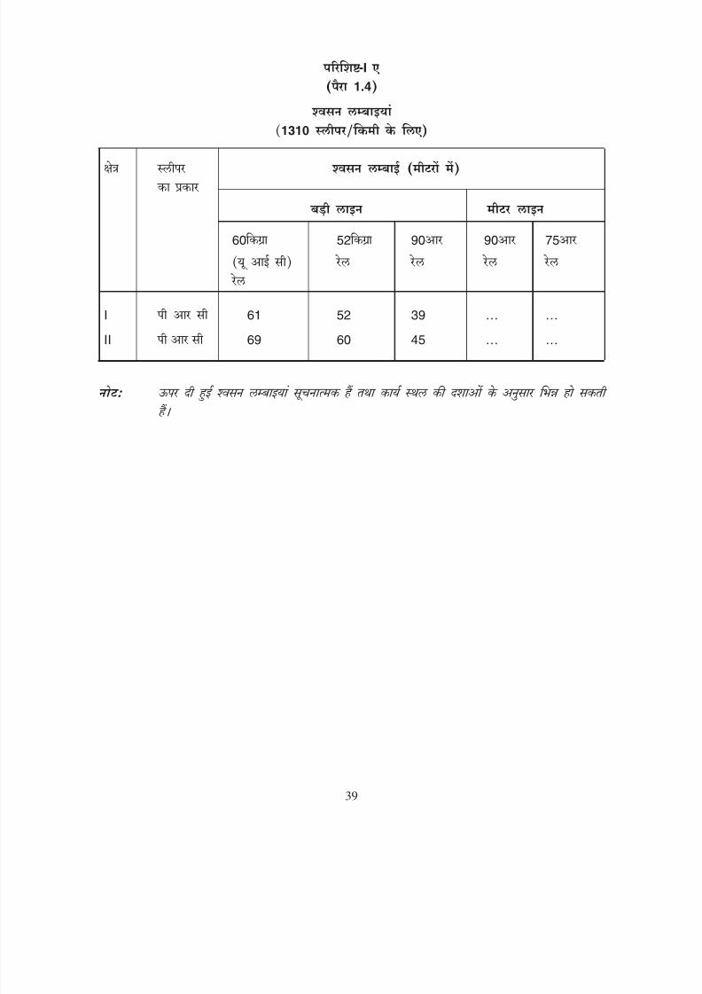
8/20/2019 lwrm
http://slidepdf.com/reader/full/lwrm 90/226
-I 1.4
1310
60 52 90 90 75
I 61 52 39 … …
I I 69 60 45 … …
39

8/20/2019 lwrm
http://slidepdf.com/reader/full/lwrm 91/226
ANNEXURE-I A
(Para 1.4)
BREATHING LENGTHS
(For 1310 sleepers/km)
Zone Type of Breathing length (in metres)
sleeper
Broad Gauge Metre Gauge
60kg(UIC) 52kg 90R 90R 75R
rails rails rails rails rails
I PRC 61 52 39 … …
I I PRC 69 60 45 … …
Note: Breathing lengths given above are indicative and are likely to vary as per site
conditions.
39
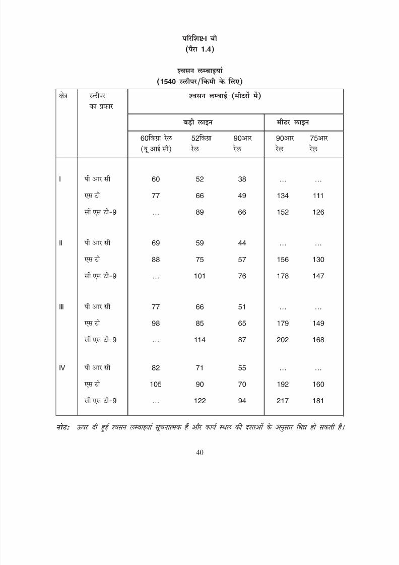
8/20/2019 lwrm
http://slidepdf.com/reader/full/lwrm 92/226
-I 1.4
1540
60 52 90 90 75
I 60 52 38 … …
77 66 49 134 111
9 … 89 66 152 126
I I 69 59 44 … …
88 75 57 156 130
9 … 101 76 178 147
III 77 66 51 … …
98 85 65 179 149
9 … 114 87 202 168
IV 82 71 55 … …
105 90 70 192 160
9 … 122 94 217 181
40
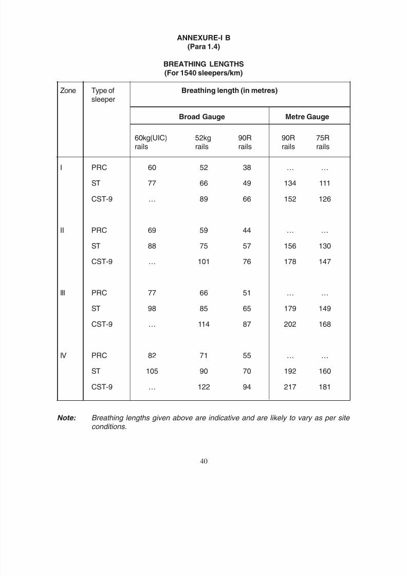
8/20/2019 lwrm
http://slidepdf.com/reader/full/lwrm 93/226
ANNEXURE-I B
(Para 1.4)
BREATHING LENGTHS
(For 1540 sleepers/km)
Zone Type of Breathing length (in metres)sleeper
Broad Gauge Metre Gauge
60kg(UIC) 52kg 90R 90R 75Rrails rails rails rails rails
I PRC 60 52 38 … …
ST 77 66 49 134 111
CST-9 … 89 66 152 126
I I PRC 69 59 44 … …
ST 88 75 57 156 130
CST-9 … 101 76 178 147
III PRC 77 66 51 … …
ST 98 85 65 179 149
CST-9 … 114 87 202 168
IV PRC 82 71 55 … …
ST 105 90 70 192 160
CST-9 … 122 94 217 181
Note: Breathing lengths given above are indicative and are likely to vary as per site conditions.
40

8/20/2019 lwrm
http://slidepdf.com/reader/full/lwrm 94/226
-I 1.4
1660
60 52 90 90 75
I 58 50 37 … …
73 63 46 … …
9 … 86 63 … …
II 66 57 43 … …
84 72 54 … …
9 … 98 74 … …
III 74 64 49 … …
94 81 62 … …
9 … 110 84 … …
IV 79 68 53 … …
100 86 67 … …
9 … 118 91 … …
41
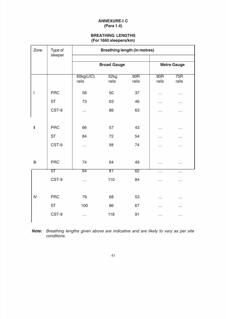
8/20/2019 lwrm
http://slidepdf.com/reader/full/lwrm 95/226
ANNEXURE-I C
(Para 1.4)
BREATHING LENGTHS
(For 1660 sleepers/km)
Zone Type of Breathing length (in metres)sleeper
Broad Gauge Metre Gauge
60kg(UIC) 52kg 90R 90R 75Rrails rails rails rails rails
I PRC 58 50 37 … …
ST 73 63 46 … …
CST-9 … 86 63 … …
II PRC 66 57 43 … …
ST 84 72 54 … …
CST-9 … 98 74 … …
III PRC 74 64 49 … …
ST 94 81 62 … …
CST-9 … 110 84 … …
IV PRC 79 68 53 … …
ST 100 86 67 … …
CST-9 … 118 91 … …
Note: Breathing lengths given above are indicative and are likely to vary as per site conditions.
41

8/20/2019 lwrm
http://slidepdf.com/reader/full/lwrm 96/226
-II 4.3.1 4.3.2
-9
i) -9
ii)
iii)
iv)
v)
vi) 75 25
vii)
viii)
-9 20
42
8/20/2019 lwrm
http://slidepdf.com/reader/full/lwrm 97/226
ANNEXURE-II
(Para 4.3.1& 4.3.2)
SUPPLEMENTARY INSTRUCTIONS FOR LAYING & MAINTENANCE OF LWR ON
CST-9 SLEEPERS ON BG
The following precautions shall be observed before laying and while maintainingLWR/CWR on CST-9 sleepers:-
i) LWR/CWR shall not preferably be provided on CST-9 sleepers in areas where
the incidence of derailment is large and/or theft of fastenings is frequent.
ii) Sleepers already in service shall have minimum wear at rail seat and jaws so thatkeys are effective.
iii) Ballast shall be heaped up in a slope from shoulder to the bottom of rail head onthe outside of track.
iv) Crib and shoulder compaction shall invariably be carried out soon after sleeperrenewal/through packing/screening/ deep screening or any other operation causingreduction of ballast resistance. Till such compaction is done, suitable speedrestriction shall be continued.
v) On single line, both keys in a sleeper should be driven in the same direction andthe keys in the next sleeper shall be in reverse direction and so on.
vi) On double line 75 percent of keys should be driven in the direction of trafficand 25 per cent in the opposite direction in the central portion of LWR/CWR.
In the breathing lengths, keys should be driven alternately in both directions onsuccessive sleepers.
vii) Attempt should be made to keep both the keys of the same sleeper uniformly tightso as to avoid plates going out of square. Whenever, a fallen key is driven back,the opposite key on the same sleeper should also be adequately driven.
viii) Wherever possible reverse jaw type plates should be replaced with ordinarytype plates, since the former afford hindrance while lifting LWR on rollers duringdestressing.
On-track tamping machine shall preferably be used for maintaining LWR/CWRlengths. In case of manual maintenance, lifting of LWR/CWR track on CST-9sleepers in excess of 20 mm shall be carried out under the supervision of anInspector not below the rank of Permanent Way Inspector/Incharge of Sub-Section.
42
8/20/2019 lwrm
http://slidepdf.com/reader/full/lwrm 98/226
ix) 3
x) 100 33 100 100
xi)
43

8/20/2019 lwrm
http://slidepdf.com/reader/full/lwrm 99/226
ix) During destressing, before the rail is supported on rollers, the rail seats should becovered by a 3 mm thick MS plate of suitable size so that the rollers do not getstuck into the slits at the rail seats. The cover plates should have two of the oppositeedges bent downwards to prevent their slipping off from the rail seats.
x) If it is not possible to drive 100 percent keys within the block period after
destressing, 33 percent keys in central portion and 100 percent of the keys in thebreathing lengths should be driven first and the traffic resumed at restricted speed.Full speed should be restored only after driving 100 percent keys and giving otherattention required.
xi) Creep shall be regularly measured at SEJs and in fixed portion of each LWRpanel and records seen by AEN and DEN for taking remedial measures, ifrequired.
43

8/20/2019 lwrm
http://slidepdf.com/reader/full/lwrm 100/226
-III
1. 1 4.4.3 ( ) 30
4.4.3 ( )
4.4.3 ( )
24
2. 20
3. 30
4.
i) 10
ii) 20
5. i) 10
ii) 20
6.
+200
i)
50
40
ii)
30
20
44

8/20/2019 lwrm
http://slidepdf.com/reader/full/lwrm 101/226
ANNEXURE-III
SCHEDULE OF SPEED RESTRICTIONS
Sl. Conditions of track Restriction
No. imposed in km/h
1. When 1 metre long fishplates (Fig. 4.4.3(a)) 30
with special clamps (Fig. 4.4.3(b))or joggled fishplates with bolted clamps(Fig. 4.4.3(c)) are used at a temporaryrail joint and there is 24 hrs. watch(both BG & MG)
2. When other clamps are used at a temporary 20
rail joint (both BG and MG)
3. When sleeper fastenings on alternate 30sleepers are loosened before destressing(both BG & MG)
4. At fracture after emergency repairs are completed:-
i) First train STOP DEAD & 10
ii) Subsequent trains 20
5. After emergency repairs to track after buckling:-
i) First train STOP DEAD & 10
ii) Subsequent trains 20
6. Speed restriction during consolidationperiod of track, after regular trackmaintenance operations when railtemperature exceeds t
d + 20OC:
i) When shoulder and crib compaction has been done:-
For BG 50 For MG 40
ii) When shoulder and crib compaction has not been done:-
For BG 30 For MG 20
44

8/20/2019 lwrm
http://slidepdf.com/reader/full/lwrm 102/226
-IV 5.5.2
90
1.
1.5 0.75
2.
0.75
45
8/20/2019 lwrm
http://slidepdf.com/reader/full/lwrm 103/226
ANNEXURE-IV
(Para 5.5.2)
HANDLING INSTRUCTIONS FOR 90 UTS AND HEAD HARDENED RAILS
1. Protection of straightness
Barely visible straightness deviations, for example, a deflection of 0.75 mmover 1.5 metres span, renders a rail unacceptable and require careful handlingand stacking. Therefore,
AVOID
- Heavy static loading
- Sudden impact or dynamic loading
- Localised point or line contact loading in stacking
- Excessive end drop and flange overlaps while lifting/moving
- Criss-cross stacking of rails of alternative layers at right angles as faras possible.
DO
- Keep rails horizontal and straight while lifting/moving
- Stack rails of same length on firm level base of well drained platform
preferably of concrete
- Stack subsequent layers on uniformly placed spacers in verticalalignment with base supports
- Keep rail ends in vertical alignment
- Place rails of shorter length in upper layers.
2. Protection of rail surface
Surface notches of even less than 0.75 mm in depth are liable to cause rail fracture
in service. Therefore,
AVOID
- Impact abrasion of rails against separators in wagons
- Round link chain slings for securing the rails.
45

8/20/2019 lwrm
http://slidepdf.com/reader/full/lwrm 104/226
3.
2500-3500
10
4.
4962
5.
46

8/20/2019 lwrm
http://slidepdf.com/reader/full/lwrm 105/226
DO
- Use conventional slings for lifting rails made of flat link chains
- Lifting of rails preferably with magnet lifting device.
3. Prevention of metallurgical damage
These rails are thermally very sensitive and are likely to develop metallurgicaldefects if exposed to localised heating, which produces very hard, brittle and
cracked metallurgical structures which may lead to sudden failures. Therefore,
AVOID
- Heating, flame cutting, on or adjacent to rails
- Contact with electric arcs and molten metal splashes, i.e. from loose cables
or adjacent welding operations.
DO
- Flame cutting when found essential, after preheating minimum of 10 cm ofrail length on either side of the cut to about 250-350OC by uniformmovement of heating torch.
4. Protection from contact with injurious substances
These rails can withstand normal degree of rusting but localised corrosion pittingmay cause subsequent rail fractures. Therefore,
AVOID
- Contact with injurious substances which produce high corrosion of asteel, i.e. acids, alkalis, salts, etc.
DO
- Stack rails on well drained platform preferably on concrete as per drawingNo. RDSO/T-4962.
5. Slinging principles
The single point slinging increases risk of bending and surface damage to therails. The overhang beyond the outer lifting point should not be greater than onehalf the distance between lifting points. Therefore,
46
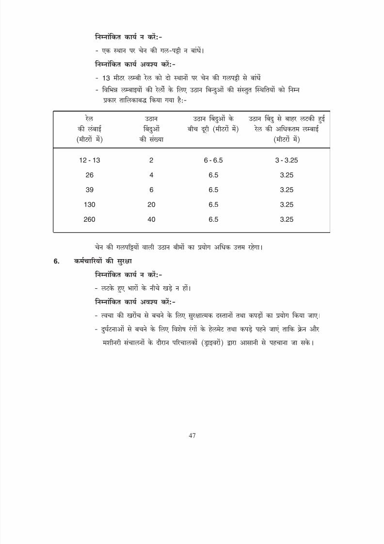
8/20/2019 lwrm
http://slidepdf.com/reader/full/lwrm 106/226
13
12 - 13 2 6 - 6.5 3 - 3.25
26 4 6.5 3.25
39 6 6.5 3.25
130 20 6.5 3.25
260 40 6.5 3.25
6.
47

8/20/2019 lwrm
http://slidepdf.com/reader/full/lwrm 107/226
AVOID
- Single point slinging.
DO
- Use two point slinging for rail length upto 13m
- Recommended locations of lifting points for various rail lengths are tabulatedbelow:
Rail length No. of lifting Distance between Max. rail
(metres) points lifting points (m) overhang (m)
12 - 13 2 6 - 6.5 3 - 3.25
26 4 6.5 3.25
39 6 6.5 3.25
130 20 6.5 3.25
260 40 6.5 3.25
Use of lifting beams fitted with slings is desirable.
6. Safety of Personnel
AVOID
- Standing under suspended loads.
DO
- Use protective gloves and clothing to minimise the risk of skin abrasion
- Wear distinctive coloured helmet and clothing for easy identification by craneand machinery drivers to avoid accidents.
47
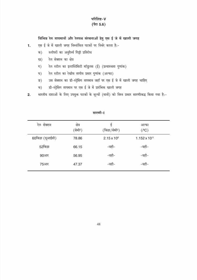
8/20/2019 lwrm
http://slidepdf.com/reader/full/lwrm 108/226
V
5.6
1.
2.
I
2
2
/ 0
C60 78.86 2.15 x 10⁶ 1.152 x 10⁻⁵
52 66.15
90 56.95
75 47.37
48

8/20/2019 lwrm
http://slidepdf.com/reader/full/lwrm 109/226
ANNEXURE-V
(Para 5.6)
GAPS AT SEJ FOR VARIOUS RAIL TEMPERATURES
AND TRACK STRUCTURES
1. Gap at SEJ depends on following factors:-
a) Longitudinal Ballast Resistance of sleepers
b) Area of rail section
c) Modulus of Elasticity (E) for rail steel
d) Coefficient of linear expansion (α) for rail steel
e) Destressing temperature of the section where gap at SEJ is required
f) Initial gap at SEJ at destressing temperature
2. Values of above variables for Indian conditions are tabulated below:-
TABLE-I
Rail Section Area E α
(cm2) (kg/cm2) ( / oC)
60kg (UIC) 78.86 2.15 x 10⁶ 1.152 x 10⁻⁵
52kg 66.15 - do - - do -
90R 56.95 - do - - do -
75R 47.37 - do - - do -
48

8/20/2019 lwrm
http://slidepdf.com/reader/full/lwrm 110/226
II
1310 1540 1660 1540
12.93 13.28 13.74 -
11.48 12.14 12.68 3.86
9 9.92 10.65 11.04 3.47
7.58 7.97 8.06 5.00
III
60 52 40
60
580
(i) 52
(ii)
49

8/20/2019 lwrm
http://slidepdf.com/reader/full/lwrm 111/226
TABLE-II
Longitudinal Ballast Resistance (R) for various sleepers and sleeper density
Type of sleeper Longitudinal Ballast Resistance in kg/cm/rail
Broad Gauge Metre Gauge
1310 1540 1660 1540sleepers/km sleepers/km sleepers/km sleepers/km
PRC 12.93 13.28 13.74 -
ST 11.48 12.14 12.68 3.86
CST-9 9.92 10.65 11.04 3.47
Wooden 7.58 7.97 8.06 5.00
Note: The values given above are indicative and can vary as per site conditions.
TABLE-III
Initial gap to be provided at destressing temperature (td)
Rail Section Initial gap at td (mm)
60kg (UIC)/52kg 40 mm
Others 60 mm
EXAMPLE:-
To find out the gap at SEJ at rail temperature of 580C with the following data:
i) Rail section 52kg/m
ii) Type of sleeper PRC
49
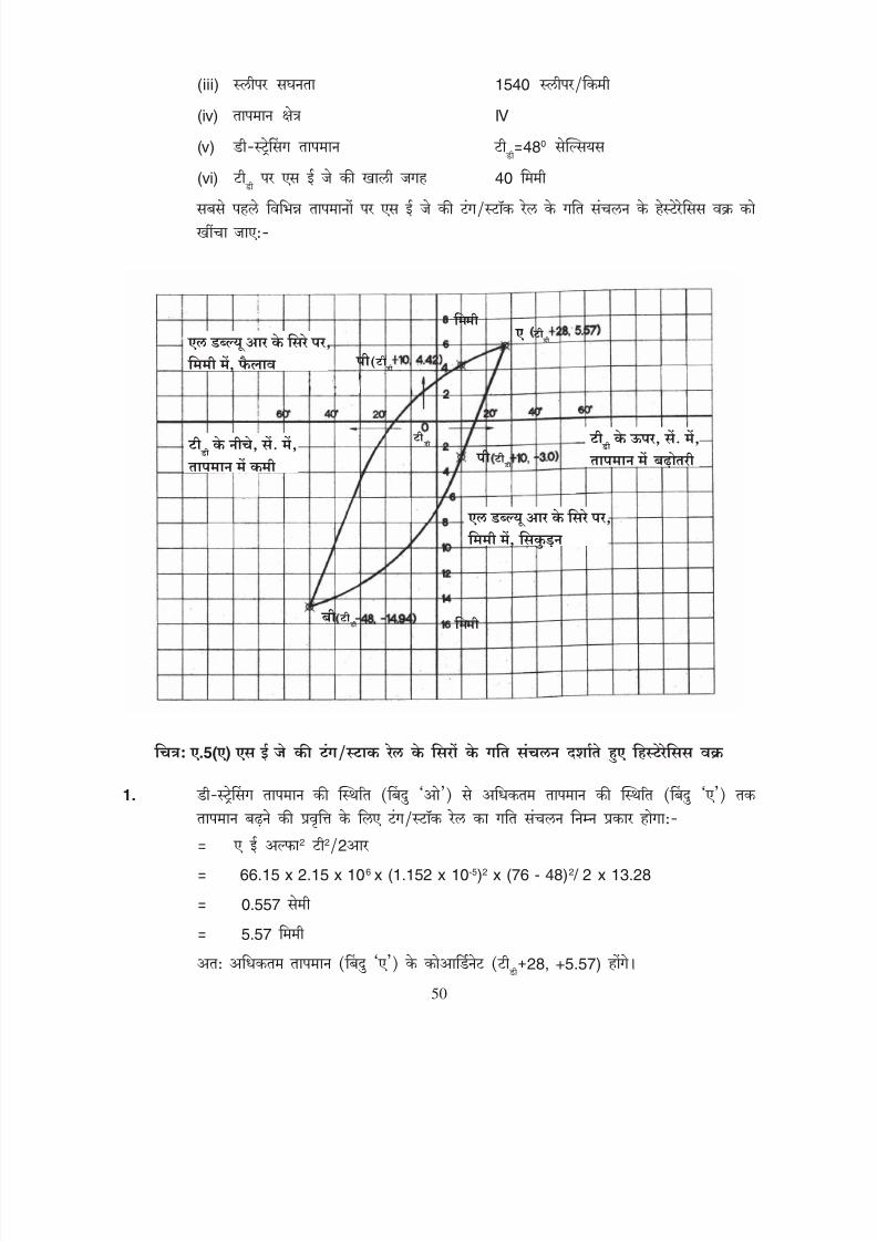
8/20/2019 lwrm
http://slidepdf.com/reader/full/lwrm 112/226
(iii) 1540
(iv) IV
(v)
480
(vi)
40
.5( )
1.
2 22
66.15 x 2.15 x 106 x (1.152 x 10-5)2 x (76 - 48)2 / 2 x 13.28
0.557
5.57
28, +5.57)
50

8/20/2019 lwrm
http://slidepdf.com/reader/full/lwrm 113/226
iii) Sleeper density 1540 sleepers/km
iv) Temp. zone IV
v) Destressing temp. td = 48OC
vi) Gap at SEJ at td
40 mm
First of all hysteresis curve of movement of tongue/stock rail of SEJ will be drawnat different temperatures.
Fig.: A.5(a) HYSTERESIS CURVE SHOWING THE MOVEMENT OF ENDS OF
TONGUE/STOCK RAIL OF SEJ
1. Movement of tongue/stock rail from the stage of destressing temperature(point ‘O’) to the stage of maximum temperature (point ‘A’) for rising trend oftemperature will be:-
= A E α2 t2 /2R
= 66.15 x 2.15 x 106 x (1.152 x 10-5)2 x (76-48)2 / 2 x 13.28
= 0.557 cm
= 5.57 mm
Hence coordinate of maximum temperature (point ‘A’) will be (td+28, +5.57).50
td
td
td
CONTRACTION AT THE
END OF LWR IN mm
RISE IN TEMPERATUREABOVE t
d IN OC
EXPANSION AT THE
END OF LWR IN mm
FALL IN TEMPERATUREBELOW t
d IN OC
td

8/20/2019 lwrm
http://slidepdf.com/reader/full/lwrm 114/226
2.
2 2 /4
66.15 x 2.15 x 106
(1.152 x 10⁻⁵
)2
x (76)2
/4 x 13.28
= 2.052
20.52
28-76, 5.57-20.52)
-48,
-14.95)
3.
66.15 x 2.15 x 106
x (1.152 x 10-5
)2
x (76)2
/4 x 13.28
= 2.052
20.52
-48+76, -14.95+20.52)
28, +5.57)
580
+10)0
4. +10)0
66.15 x 2.15 x 106 x (1.152 x 10-5)2 x (76-58)2 /4 x 13.28
= 0.115
1.15
10, 5.57-1.15)
10, +4.42)
5. 10)0
66.15 x 2.15 x 106 x (1.152 x 10-5)2 x (58)2 /4 x 13.28
1.195
11.95
51

8/20/2019 lwrm
http://slidepdf.com/reader/full/lwrm 115/226
2. Movement of tongue/stock rail from stage of maximum temperature (point ‘A’)to stage of minimum temperature (point ‘B’) for decreasing trend of temperaturewill be:-
= A E α2 t2 /4R
= 66.15 x 2.15 x 106 x (1.152 x 10-5)2 x (76)2 /4x 13.28
= 2.052 cm
= 20.52 mm
Hence coordinate of minimum temperature (point ‘B’) will be
(td+28 - 76, 5.57-20.52)
or (td - 48, -14.95)
3. Movement of tongue/stock rail from stage of minimum temperature (point ‘B’)to stage of maximum temperature (point ‘A’) for increasing trend of temperaturewill be:-
= 66.15x 2.15 x 106 x (1.152 x 10-5)2 x (76)2 / 4 x 13.28
= 2.052 cm
= 20.52 mm
Hence coordinate of maximum temperature (point ‘A’) will be
(td- 48+76, -14.95 + 20.52)
or (td+28, +5.57)
Temperature at which gap at SEJ is required is 580C i.e. (td+10)0C say point ‘P’.
4. Value of movement of tongue/stock rail at (td+10)0
C point ‘P’ for falling trend oftemperature will be
= 66.15 x 2.15 x 106 x (1.152 x 10-5)2 x (76 - 58)2 /4x 13.28
= 0.115 cm
= 1.15 mm
Hence coordinate at point ‘P’ for falling trend of temperature will be:-
(td+10, 5.57-1.15)
or (td+10, +4.42)
5. In the same way, value of movement of tongue/stock at (td+10)0C point ‘P’ forrising trend of temperature will be:-
= 66.15 x 2.15 x 106 x (1.152 x 10-5)2 x (58)2 /4x 13.28
= 1.195 cm
= 11.95 mm
51
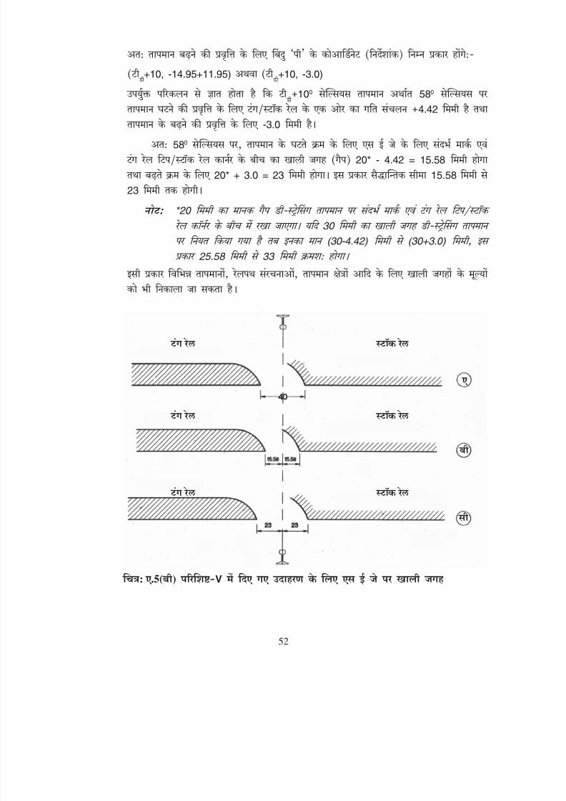
8/20/2019 lwrm
http://slidepdf.com/reader/full/lwrm 116/226
+10, -14.95+11.95)
+10, -3.0)
100 580 4.42
-3.0 580
20* - 4.42 = 15.58 20* + 3.0 = 23 15.58 23
*20 30 (30-4.42) (30+3.0)
25.58 33
: .5( ) V
52
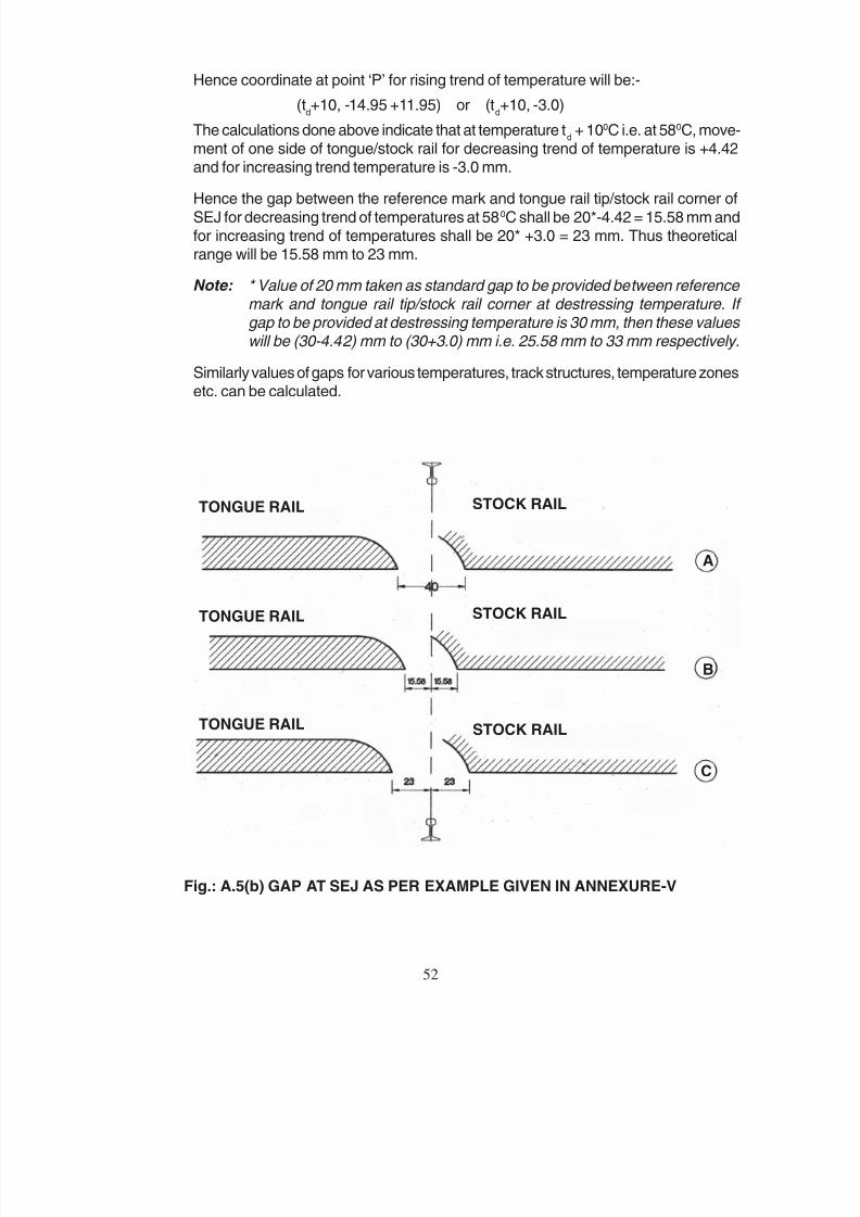
8/20/2019 lwrm
http://slidepdf.com/reader/full/lwrm 117/226
52
Hence coordinate at point ‘P’ for rising trend of temperature will be:-
(td+10, -14.95 +11.95) or (t
d+10, -3.0)
The calculations done above indicate that at temperature td + 100C i.e. at 580C, move-
ment of one side of tongue/stock rail for decreasing trend of temperature is +4.42and for increasing trend temperature is -3.0 mm.
Hence the gap between the reference mark and tongue rail tip/stock rail corner of
SEJ for decreasing trend of temperatures at 580C shall be 20*-4.42 = 15.58 mm andfor increasing trend of temperatures shall be 20* +3.0 = 23 mm. Thus theoreticalrange will be 15.58 mm to 23 mm.
Note: * Value of 20 mm taken as standard gap to be provided between reference mark and tongue rail tip/stock rail corner at destressing temperature. If gap to be provided at destressing temperature is 30 mm, then these values will be (30-4.42) mm to (30+3.0) mm i.e. 25.58 mm to 33 mm respectively.
Similarly values of gaps for various temperatures, track structures, temperature zonesetc. can be calculated.
Fig.: A.5(b) GAP AT SEJ AS PER EXAMPLE GIVEN IN ANNEXURE-V
TONGUE RAIL
TONGUE RAIL
TONGUE RAIL
STOCK RAIL
STOCK RAIL
STOCK RAIL
A
B
C

8/20/2019 lwrm
http://slidepdf.com/reader/full/lwrm 118/226
V
60 1660 13.74
1.11
-I -II -III -IV
+ 28 - - - 14
+ 25 - - 15 14 16
+ 20 - 17 15 18 14 18
+ 15 18 17 19 15 20 14 21
+ 10 18 20 17 21 16 23 15 23
+ 05 19 22 18 23 17 25 16 26
19 23 18 25 18 27 17 28
- 05 20 25 19 26 19 28 18 29
- 10 21 26 20 28 20 30 20 31
- 15 22 27 22 29 21 31 21 32
- 20 23 27 23 30 23 32 23 34
- 25 25 28 25 30 25 33 25 35
- 30 26 28 27 31 27 34 27 36
- 35 28 29 31 29 34 29 36
- 40 - 31 32 34 32 37
- 45 - - 35 35 37
- 48 - - - 37
40 60 10
53

8/20/2019 lwrm
http://slidepdf.com/reader/full/lwrm 119/226
ANNEXURE-V
GAPS BETWEEN THE REFERENCE MARK AND TONGUE RAIL TIP/STOCK RAIL COR-NER OF SEJ FOR VARIOUS TEMPERATURES IN mm FOR BG, 60kg, PRC SLEEPER, 1660Nos/ km , VALUE OF R (BALLAST RESISTANCE) ASSUMED = 13.74 kg/cm/rail AND t
d AS
PER PARA 1.11:-
Temperature Zone-I Zone-II Zone-III Zone-IV
td+ 28 - - - 14
td + 25 - - 15 14 to 16
td + 20 - 17 15 to 18 14 to 18
td+ 15 18 17 to 19 15 to 20 14 to 21
td+ 10 18 to 20 17 to 21 16 to 23 15 to 23
td+ 05 19 to 22 18 to 23 17 to 25 16 to 26
td
19 to 23 18 to 25 18 to 27 17 to 28
td - 05 20 to 25 19 to 26 19 to 28 18 to 29
td- 10 21 to 26 20 to 28 20 to 30 20 to 31
td- 15 22 to 27 22 to 29 21 to 31 21 to 32
td- 20 23 to 27 23 to 30 23 to 32 23 to 34
td- 25 25 to 28 25 to 30 25 to 33 25 to 35
td- 30 26 to 28 27 to 31 27 to 34 27 to 36
td- 35 28 29 to 31 29 to 34 29 to 36
td- 40 - 31 32 to 34 32 to 37
td - 45 - - 35 35 to 37
td- 48 - - - 37
Note: The above values have been calculated with initial setting of gaps at SEJ as 40 mm. Where SEJs had initially been set with a gap of 60 mm, 10 mm should be added to each of above values for comparison of gaps at site.
53

8/20/2019 lwrm
http://slidepdf.com/reader/full/lwrm 120/226
-V
60 1540
13.28
1.11
-I -II -III -IV
+ 28 - - - 13
+ 25 - - 15 13 14
+ 20 - 17 15 18 14 15
+ 15 18 17 19 15 20 14 18
+ 10 18 20 17 21 16 23 14 21
+ 05 19 22 18 23 16 25 16 26
19 23 18 25 17 27 17 28
- 05 20 25 19 27 19 28 18 30
- 10 21 26 20 28 20 30 20 31
- 15 22 27 22 29 21 31 21 33
- 20 23 28 23 30 23 32 23 34
- 25 25 28 25 31 25 33 25 35
- 30 27 28 27 31 27 34 27 36
- 35 28 29 31 30 35 30 37
- 40 - 32 32 35 33 37
- 45 - - 35 36 37
- 48 - - - 37
40 60 10
54

8/20/2019 lwrm
http://slidepdf.com/reader/full/lwrm 121/226
ANNEXURE-V
GAPS BETWEEN THE REFERENCE MARK AND TONGUE RAIL TIP/STOCK RAILCORNER OF SEJ FOR VARIOUS TEMPERATURES IN mm FOR BG, 60 kg, PRCSLEEPER, 1540 Nos/km, VALUE OF R (BALLAST RESISTANCE) ASSUMED= 13.28 kg/cm/rail AND t
d AS PER PARA 1.11:-
Temperature Zone-I Zone-II Zone-III Zone-IV
td + 28 - - - 13
td + 25 - - 15 13 to 14
td + 20 - 17 15 to 18 14 to 15
td + 15 18 17 to19 15 to 20 14 to 18
td + 10 18 to 20 17 to 21 16 to 23 14 to 21
td + 05 19 to 22 18 to 23 16 to 25 16 to 26
td
19 to 23 18 to 25 17 to 27 17 to 28
td - 05 20 to 25 19 to 27 19 to 28 18 to 30
td - 10 21 to 26 20 to 28 20 to 30 20 to 31
td - 15 22 to 27 22 to 29 21 to 31 21 to 33
td - 20 23 to 28 23 to 30 23 to 32 23 to 34
td - 25 25 to 28 25 to 31 25 to 33 25 to 35
td - 30 27 to 28 27 to 31 27 to 34 27 to 36
td - 35 28 29 to 31 30 to 35 30 to 37
td - 40 - 32 32 to 35 33 to 37
td - 45 - - 35 36 to 37
td - 48 - - - 37
Note: The above values have been calculated with initial setting of gaps at SEJ as 40 mm. Where SEJs had initially been set with a gap of 60 mm, 10 mm should be added to each of above values for comparison of gaps at site.
54
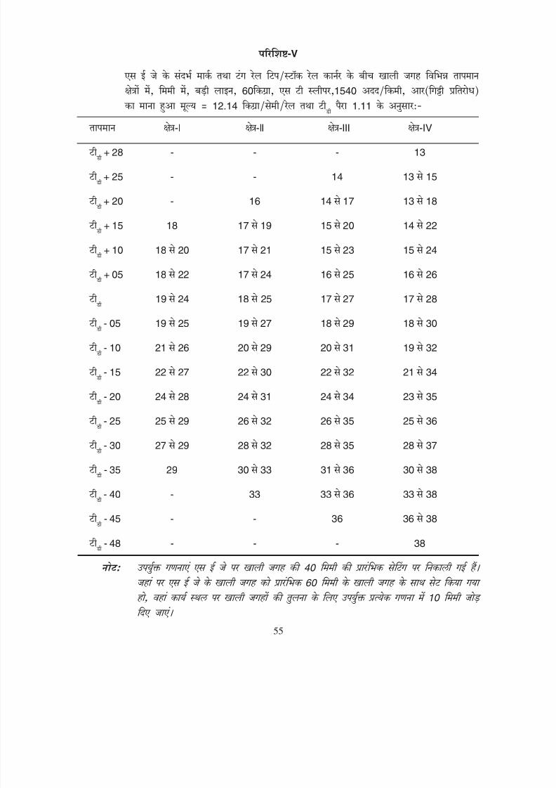
8/20/2019 lwrm
http://slidepdf.com/reader/full/lwrm 122/226
-V
60 1540
12.14
1.11
-I -II -III -IV
+ 28 - - - 13
+ 25 - - 14 13 15
+ 20 - 16 14 17 13 18
+ 15 18 17 19 15 20 14 22
+ 10 18 20 17 21 15 23 15 24
+ 05 18 22 17 24 16 25 16 26
19 24 18 25 17 27 17 28
- 05 19 25 19 27 18 29 18 30
- 10 21 26 20 29 20 31 19 32
- 15 22 27 22 30 22 32 21 34
- 20 24 28 24 31 24 34 23 35
- 25 25 29 26 32 26 35 25 36
- 30 27 29 28 32 28 35 28 37
- 35 29 30 33 31 36 30 38
- 40 - 33 33 36 33 38
- 45 - - 36 36 38
- 48 - - - 38
40 60 10
55
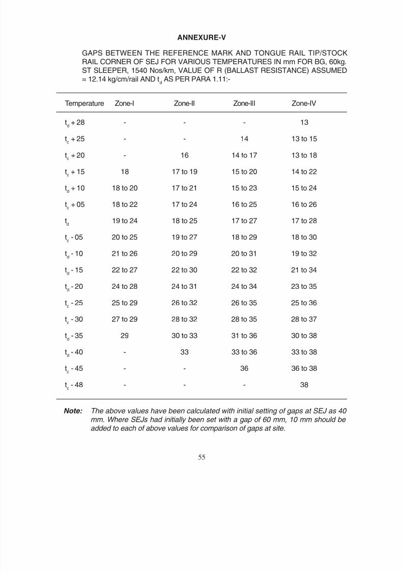
8/20/2019 lwrm
http://slidepdf.com/reader/full/lwrm 123/226
ANNEXURE-V
GAPS BETWEEN THE REFERENCE MARK AND TONGUE RAIL TIP/STOCKRAIL CORNER OF SEJ FOR VARIOUS TEMPERATURES IN mm FOR BG, 60kg.ST SLEEPER, 1540 Nos/km, VALUE OF R (BALLAST RESISTANCE) ASSUMED= 12.14 kg/cm/rail AND t
d AS PER PARA 1.11:-
Temperature Zone-I Zone-II Zone-III Zone-IV
td + 28 - - - 13
td + 25 - - 14 13 to 15
td + 20 - 16 14 to 17 13 to 18
td + 15 18 17 to 19 15 to 20 14 to 22
td + 10 18 to 20 17 to 21 15 to 23 15 to 24
td + 05 18 to 22 17 to 24 16 to 25 16 to 26
td
19 to 24 18 to 25 17 to 27 17 to 28
td - 05 20 to 25 19 to 27 18 to 29 18 to 30
td - 10 21 to 26 20 to 29 20 to 31 19 to 32
td - 15 22 to 27 22 to 30 22 to 32 21 to 34
td - 20 24 to 28 24 to 31 24 to 34 23 to 35
td - 25 25 to 29 26 to 32 26 to 35 25 to 36
td - 30 27 to 29 28 to 32 28 to 35 28 to 37
td - 35 29 30 to 33 31 to 36 30 to 38
td - 40 - 33 33 to 36 33 to 38
td - 45 - - 36 36 to 38
td - 48 - - - 38
Note: The above values have been calculated with initial setting of gaps at SEJ as 40 mm. Where SEJs had initially been set with a gap of 60 mm, 10 mm should be added to each of above values for comparison of gaps at site.
55

8/20/2019 lwrm
http://slidepdf.com/reader/full/lwrm 124/226
-V
52 1660
13.74
1.11
-I -II -III -IV
+ 28 - - - 15
+ 25 - - 16 15 16
+ 20 - 17 16 18 15 19
+ 15 18 17 19 16 20 15 21
+ 10 19 20 18 21 17 22 16 23
+ 05 19 22 18 23 17 24 16 25
19 23 19 24 18 26 17 27
- 05 20 24 19 25 19 27 18 28
- 10 21 25 20 27 20 28 20 30
- 15 22 26 21 27 21 29 21 31
- 20 23 26 23 28 23 30 23 32
- 25 24 27 24 29 24 31 24 33
- 30 25 27 26 29 26 32 26 33
- 35 27 28 30 28 32 28 34
- 40 - 30 30 32 31 34
- 45 - - 33 33 34
- 48 - - - 34
40 60 10
56
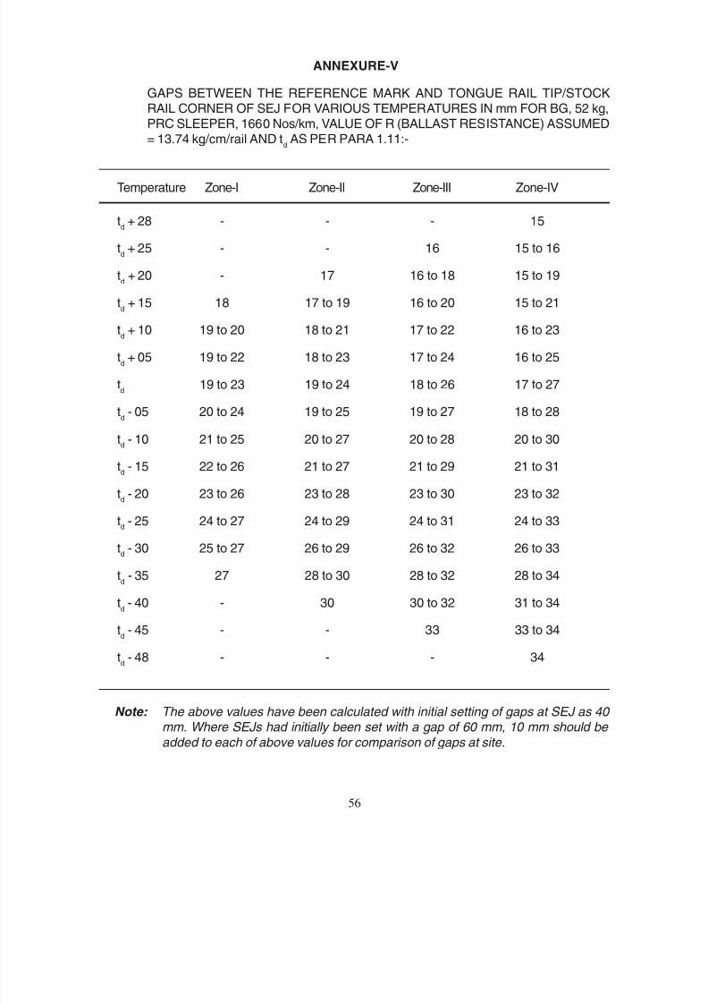
8/20/2019 lwrm
http://slidepdf.com/reader/full/lwrm 125/226
ANNEXURE-V
GAPS BETWEEN THE REFERENCE MARK AND TONGUE RAIL TIP/STOCKRAIL CORNER OF SEJ FOR VARIOUS TEMPERATURES IN mm FOR BG, 52 kg,PRC SLEEPER, 1660 Nos/km, VALUE OF R (BALLAST RESISTANCE) ASSUMED= 13.74 kg/cm/rail AND t
d AS PER PARA 1.11:-
Temperature Zone-I Zone-II Zone-III Zone-IV
td + 28 - - - 15
td + 25 - - 16 15 to 16
td + 20 - 17 16 to 18 15 to 19
td + 15 18 17 to 19 16 to 20 15 to 21
td + 10 19 to 20 18 to 21 17 to 22 16 to 23
td + 05 19 to 22 18 to 23 17 to 24 16 to 25
td
19 to 23 19 to 24 18 to 26 17 to 27
td - 05 20 to 24 19 to 25 19 to 27 18 to 28
td - 10 21 to 25 20 to 27 20 to 28 20 to 30
td - 15 22 to 26 21 to 27 21 to 29 21 to 31
td - 20 23 to 26 23 to 28 23 to 30 23 to 32
td - 25 24 to 27 24 to 29 24 to 31 24 to 33
td - 30 25 to 27 26 to 29 26 to 32 26 to 33
td - 35 27 28 to 30 28 to 32 28 to 34
td - 40 - 30 30 to 32 31 to 34
td - 45 - - 33 33 to 34
td - 48 - - - 34
Note: The above values have been calculated with initial setting of gaps at SEJ as 40 mm. Where SEJs had initially been set with a gap of 60 mm, 10 mm should be
added to each of above values for comparison of gaps at site.
56

8/20/2019 lwrm
http://slidepdf.com/reader/full/lwrm 126/226
-V
52 1540
13.28
1.11
-I -II -III -IV
+ 28 - - - 14
+ 25 - - 16 14 16
+ 20 - 17 16 18 15 19
+ 15 18 17 19 16 20 15 21
+ 10 1 8 20 18 21 16 22 16 23
+ 05 19 22 18 23 17 24 16 25
19 23 19 24 18 26 17 27
- 05 20 24 19 26 19 27 18 28
- 10 21 25 20 27 20 29 20 30
- 15 22 26 22 28 21 30 21 31
- 20 23 26 23 29 23 31 23 32
- 25 24 27 24 29 24 32 24 33
- 30 26 27 26 30 26 32 26 34
- 35 27 28 30 28 33 29 34
- 40 - 30 31 33 31 35
- 45 - - 33 33 35
- 48 - - - 35
40 60 10
57
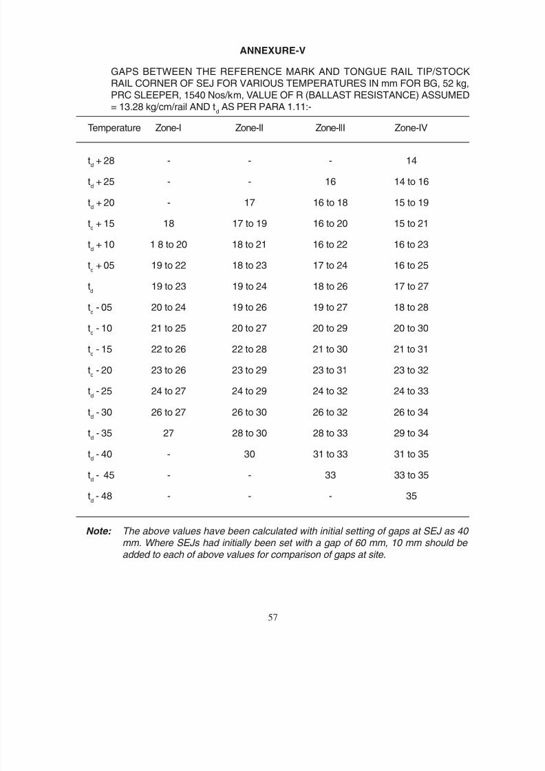
8/20/2019 lwrm
http://slidepdf.com/reader/full/lwrm 127/226
ANNEXURE-V
GAPS BETWEEN THE REFERENCE MARK AND TONGUE RAIL TIP/STOCKRAIL CORNER OF SEJ FOR VARIOUS TEMPERATURES IN mm FOR BG, 52 kg,PRC SLEEPER, 1540 Nos/km, VALUE OF R (BALLAST RESISTANCE) ASSUMED= 13.28 kg/cm/rail AND t
d AS PER PARA 1.11:-
Temperature Zone-I Zone-II Zone-III Zone-IV
td + 28 - - - 14
td + 25 - - 16 14 to 16
td + 20 - 17 16 to 18 15 to 19
td + 15 18 17 to 19 16 to 20 15 to 21
td + 10 1 8 to 20 18 to 21 16 to 22 16 to 23
td + 05 19 to 22 18 to 23 17 to 24 16 to 25
td
19 to 23 19 to 24 18 to 26 17 to 27
td - 05 20 to 24 19 to 26 19 to 27 18 to 28
td - 10 21 to 25 20 to 27 20 to 29 20 to 30
td - 15 22 to 26 22 to 28 21 to 30 21 to 31
td - 20 23 to 26 23 to 29 23 to 31 23 to 32
td - 25 24 to 27 24 to 29 24 to 32 24 to 33
td - 30 26 to 27 26 to 30 26 to 32 26 to 34
td - 35 27 28 to 30 28 to 33 29 to 34
td - 40 - 30 31 to 33 31 to 35
td - 45 - - 33 33 to 35
td - 48 - - - 35
Note: The above values have been calculated with initial setting of gaps at SEJ as 40 mm. Where SEJs had initially been set with a gap of 60 mm, 10 mm should be added to each of above values for comparison of gaps at site.
57

8/20/2019 lwrm
http://slidepdf.com/reader/full/lwrm 128/226
-V
52 1540
12.14
1.11
-I -II -III -IV
+ 28 - - - 14
+ 25 - - 15 14 16
+ 20 - 17 15 18 14 18
+ 15 18 17 19 16 20 15 22
+ 10 18 20 17 21 16 22 15 23
+ 05 19 22 18 23 17 24 16 25
19 23 18 25 18 26 17 27
- 05 20 24 19 26 19 28 18 29
- 10 22 26 20 27 20 29 20 31
- 15 22 26 22 28 21 31 21 32
- 20 23 27 23 28 23 32 23 33
- 25 24 28 25 30 25 33 25 34
- 30 26 28 27 30 27 33 27 35
- 35 28 29 31 29 34 29 36
- 40 - 31 32 34 32 36
- 45 - - 34 35 36
- 48 - - - 36
40 60 10
58
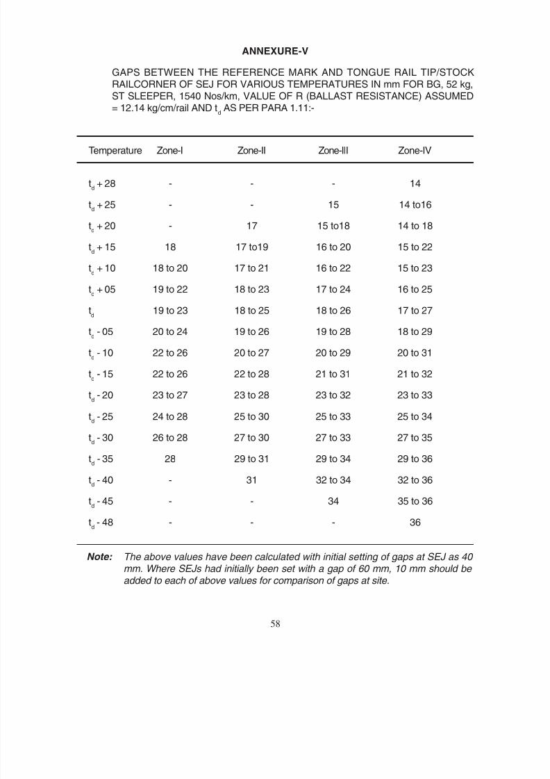
8/20/2019 lwrm
http://slidepdf.com/reader/full/lwrm 129/226
ANNEXURE-V
GAPS BETWEEN THE REFERENCE MARK AND TONGUE RAIL TIP/STOCKRAILCORNER OF SEJ FOR VARIOUS TEMPERATURES IN mm FOR BG, 52 kg,ST SLEEPER, 1540 Nos/km, VALUE OF R (BALLAST RESISTANCE) ASSUMED= 12.14 kg/cm/rail AND t
d AS PER PARA 1.11:-
Temperature Zone-I Zone-II Zone-III Zone-IV
td + 28 - - - 14
td + 25 - - 15 14 to16
td + 20 - 17 15 to18 14 to 18
td + 15 18 17 to19 16 to 20 15 to 22
td + 10 18 to 20 17 to 21 16 to 22 15 to 23
td + 05 19 to 22 18 to 23 17 to 24 16 to 25
td
19 to 23 18 to 25 18 to 26 17 to 27
td - 05 20 to 24 19 to 26 19 to 28 18 to 29
td - 10 22 to 26 20 to 27 20 to 29 20 to 31
td - 15 22 to 26 22 to 28 21 to 31 21 to 32
td - 20 23 to 27 23 to 28 23 to 32 23 to 33
td - 25 24 to 28 25 to 30 25 to 33 25 to 34
td - 30 26 to 28 27 to 30 27 to 33 27 to 35
td - 35 28 29 to 31 29 to 34 29 to 36
td - 40 - 31 32 to 34 32 to 36
td - 45 - - 34 35 to 36
td - 48 - - - 36
Note: The above values have been calculated with initial setting of gaps at SEJ as 40 mm. Where SEJs had initially been set with a gap of 60 mm, 10 mm should be added to each of above values for comparison of gaps at site.
58

8/20/2019 lwrm
http://slidepdf.com/reader/full/lwrm 130/226
-V
52 9 1540
10.65
1.11
-I -II -III -IV
+ 28 - - - 13
+ 25 - - 14 13 15
+ 20 - 16 15 17 13 18
+ 15 18 17 19 15 20 14 21
+ 10 18 20 17 21 15 23 15 24
+ 05 18 22 17 23 16 25 15 26
19 24 18 25 17 27 17 28
- 05 20 25 19 27 18 29 18 30
- 10 21 26 20 28 20 31 19 32
- 15 22 27 22 30 22 32 22 34
- 20 23 28 24 31 23 33 23 35
- 25 25 29 25 31 26 34 26 36
- 30 27 29 28 32 28 35 28 37
- 35 29 30 32 30 36 31 38
- 40 - 32 33 36 34 38
- 45 - - 36 37 39
- 48 - - - 39
40 60 10
59
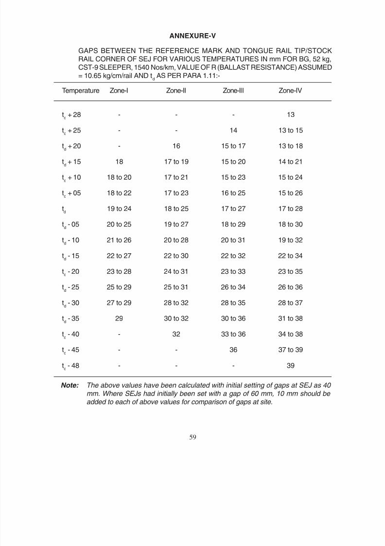
8/20/2019 lwrm
http://slidepdf.com/reader/full/lwrm 131/226
ANNEXURE-V
GAPS BETWEEN THE REFERENCE MARK AND TONGUE RAIL TIP/STOCKRAIL CORNER OF SEJ FOR VARIOUS TEMPERATURES IN mm FOR BG, 52 kg,CST-9 SLEEPER, 1540 Nos/km, VALUE OF R (BALLAST RESISTANCE) ASSUMED= 10.65 kg/cm/rail AND t
d AS PER PARA 1.11:-
Temperature Zone-I Zone-II Zone-III Zone-IV
td + 28 - - - 13
td + 25 - - 14 13 to 15
td + 20 - 16 15 to 17 13 to 18
td + 15 18 17 to 19 15 to 20 14 to 21
td + 10 18 to 20 17 to 21 15 to 23 15 to 24
td + 05 18 to 22 17 to 23 16 to 25 15 to 26
td
19 to 24 18 to 25 17 to 27 17 to 28
td - 05 20 to 25 19 to 27 18 to 29 18 to 30
td - 10 21 to 26 20 to 28 20 to 31 19 to 32
td - 15 22 to 27 22 to 30 22 to 32 22 to 34
td - 20 23 to 28 24 to 31 23 to 33 23 to 35
td - 25 25 to 29 25 to 31 26 to 34 26 to 36
td - 30 27 to 29 28 to 32 28 to 35 28 to 37
td - 35 29 30 to 32 30 to 36 31 to 38
td - 40 - 32 33 to 36 34 to 38
td - 45 - - 36 37 to 39
td - 48 - - - 39
Note: The above values have been calculated with initial setting of gaps at SEJ as 40 mm. Where SEJs had initially been set with a gap of 60 mm, 10 mm should be added to each of above values for comparison of gaps at site.
59
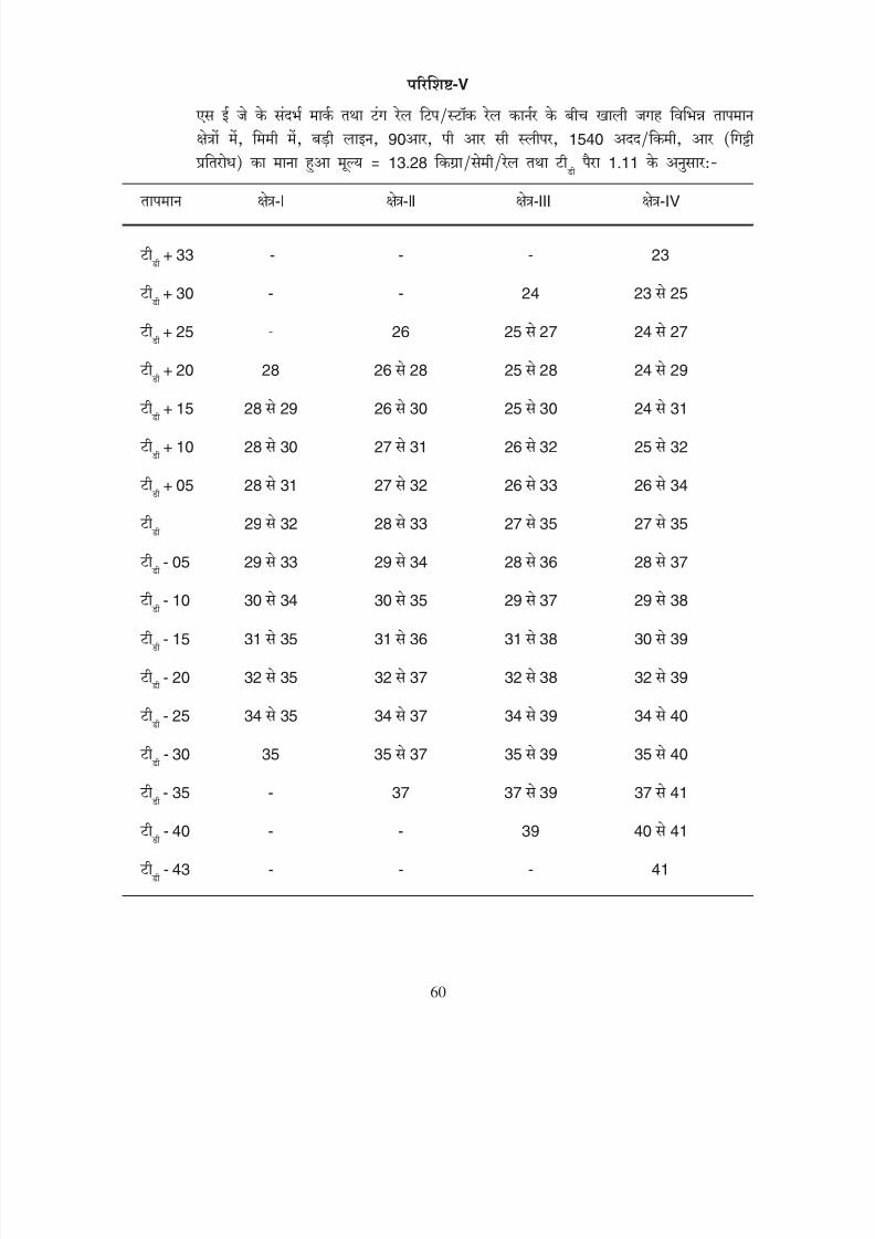
8/20/2019 lwrm
http://slidepdf.com/reader/full/lwrm 132/226
-V
90 1540
13.28
1.11
-I -II -III -IV
+ 33 - - - 23
+ 30 - - 24 23 25
+ 25 - 26 25 27 24 27
+ 20 28 26 28 25 28 24 29
+ 15 28 29 26 30 25 30 24 31
+ 10 28 30 27 31 26 32 25 32
+ 05 28 31 27 32 26 33 26 34
29 32 28 33 27 35 27 35
- 05 29 33 29 34 28 36 28 37
- 10 30 34 30 35 29 37 29 38
- 15 31 35 31 36 31 38 30 39
- 20 32 35 32 37 32 38 32 39
- 25 34 35 34 37 34 39 34 40
- 30 35 35 37 35 39 35 40
- 35 - 37 37 39 37 41
- 40 - - 39 40 41
- 43 - - - 41
60

8/20/2019 lwrm
http://slidepdf.com/reader/full/lwrm 133/226
ANNEXURE-V
GAPS BETWEEN THE REFERENCE MARK AND TONGUE RAIL TIP/STOCK
RAIL CORNER OF SEJ FOR VARIOUS TEMPERATURES IN mm FOR BG, 90R,PRC SLEEPER, 1540 Nos/km, VALUE OF R (BALLAST RESISTANCE) ASSUMED= 13.28 kg/cm/rail AND t
d AS PER PARA 1.11:-
Temperature Zone-I Zone-II Zone-III Zone-sIV
td + 33 - - - 23
td + 30 - - 24 23 to 25
td + 25 - 26 25 to 27 24 to 27
td
+ 20 28 26 to 28 25 to 28 24 to 29
td + 15 28 to 29 26 to 30 25 to 30 24 to 31
td + 10 28 to 30 27 to 31 26 to 32 25 to 32
td + 05 28 to 31 27 to 32 26 to 33 26 to 34
td
29 to 32 28 to 33 27 to 35 27 to 35
td - 05 29 to 33 29 to 34 28 to 36 28 to 37
td - 10 30 to 34 30 to 35 29 to 37 29 to 38
td - 15 31 to 35 31 to 36 31 to 38 30 to 39
td - 20 32 to 35 32 to 37 32 to 38 32 to 39
td - 25 34 to 35 34 to 37 34 to 39 34 to 40
td - 30 35 35 to 37 35 to 39 35 to 40
td - 35 - 37 37 to 39 37 to 41
td - 40 - - 39 40 to 41
td - 43 - - - 41
60

8/20/2019 lwrm
http://slidepdf.com/reader/full/lwrm 134/226
-V
90 1540
12.14
1.11
-I -II -III -IV
+ 33 - - - 23
+ 30 - - 24 23 24
+ 25 - 26 24 26 23 27
+ 20 27 26 28 24 28 23 29
+ 15 27 29 26 30 25 30 24 31
+ 10 28 30 27 31 25 32 24 33
+ 05 28 32 27 33 26 34 25 34
29 33 28 34 27 35 26 36
- 05 29
34 29
35 28
36 28
37
- 10 30 34 30 36 29 37 29 38
- 15 31 35 31 37 31 38 30 39
- 20 33 35 33 37 32 39 32 40
- 25 34 36 34 38 34 40 34 41
- 30 36 36 38 36 40 36 41
- 35 - 38 38 40 38 42
- 40 - - 40 40 42
- 43 - - - 42
61
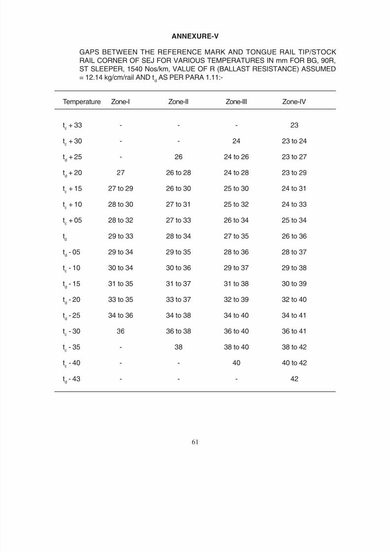
8/20/2019 lwrm
http://slidepdf.com/reader/full/lwrm 135/226
ANNEXURE-V
GAPS BETWEEN THE REFERENCE MARK AND TONGUE RAIL TIP/STOCK
RAIL CORNER OF SEJ FOR VARIOUS TEMPERATURES IN mm FOR BG, 90R,ST SLEEPER, 1540 Nos/km, VALUE OF R (BALLAST RESISTANCE) ASSUMED= 12.14 kg/cm/rail AND t
d AS PER PARA 1.11:-
Temperature Zone-I Zone-II Zone-III Zone-IV
td + 33 - - - 23
td + 30 - - 24 23 to 24
td + 25 - 26 24 to 26 23 to 27
td + 20 27 26 to 28 24 to 28 23 to 29
td + 15 27 to 29 26 to 30 25 to 30 24 to 31
td + 10 28 to 30 27 to 31 25 to 32 24 to 33
td + 05 28 to 32 27 to 33 26 to 34 25 to 34
td
29 to 33 28 to 34 27 to 35 26 to 36
td - 05 29 to 34 29 to 35 28 to 36 28 to 37
td - 10 30 to 34 30 to 36 29 to 37 29 to 38
td - 15 31 to 35 31 to 37 31 to 38 30 to 39
td - 20 33 to 35 33 to 37 32 to 39 32 to 40
td - 25 34 to 36 34 to 38 34 to 40 34 to 41
td - 30 36 36 to 38 36 to 40 36 to 41
td - 35 - 38 38 to 40 38 to 42
td - 40 - - 40 40 to 42
td - 43 - - - 42
61
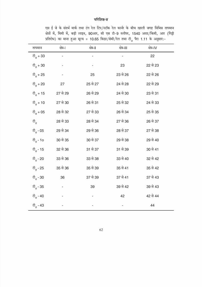
8/20/2019 lwrm
http://slidepdf.com/reader/full/lwrm 136/226
-V
90 9 1540
10.65
1.11
-I -II -III -IV
+ 33 - - - 22
+ 30 - - 23 22 23
+ 25 - 25 23 26 22 26
+ 20 27 25 27 24 28 22 29
+ 15 27 29 26 29 24 30 23 31
+ 10 27 30 26 31 25 32 24 33
+ 05 28 32 27 33 26 34 25 35
28 33 28 34 27 36 26 37
- 05 29 34 29 36 28 37 27 38
- 1o 30 35 30 37 29 38 29 40
- 15 32 36 31 37 31 39 30 41
- 20 33 36 33 38 33 40 32 42
- 25 35 36 35 39 35 41 35 42
- 30 36 37 39 37 41 37 43
- 35 - 39 39 42 39 43
- 40 - - 42 42 44
- 43 - - - 44
62
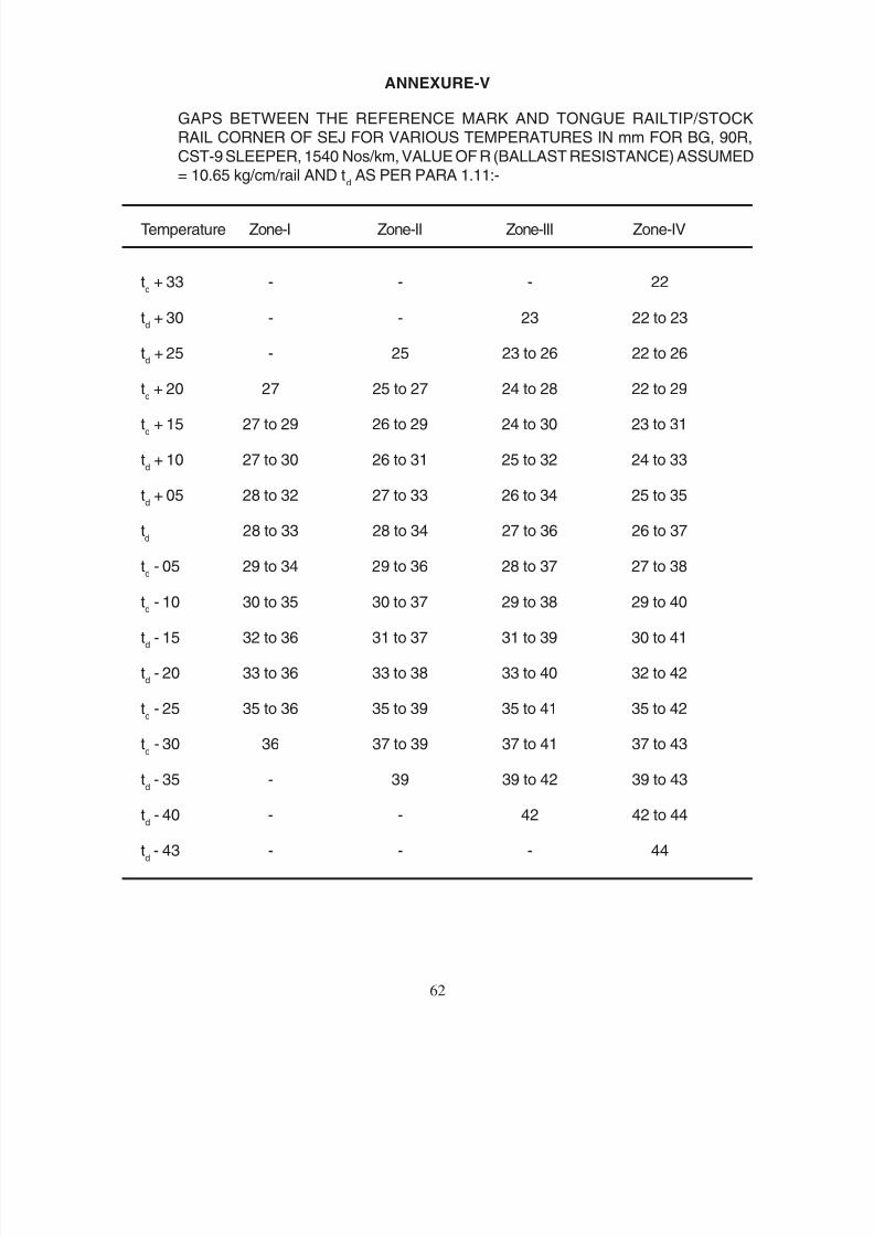
8/20/2019 lwrm
http://slidepdf.com/reader/full/lwrm 137/226
ANNEXURE-V
GAPS BETWEEN THE REFERENCE MARK AND TONGUE RAILTIP/STOCKRAIL CORNER OF SEJ FOR VARIOUS TEMPERATURES IN mm FOR BG, 90R,
CST-9 SLEEPER, 1540 Nos/km, VALUE OF R (BALLAST RESISTANCE) ASSUMED= 10.65 kg/cm/rail AND t
d AS PER PARA 1.11:-
Temperature Zone-I Zone-II Zone-III Zone-IV
td + 33 - - - 22
td + 30 - - 23 22 to 23
td + 25 - 25 23 to 26 22 to 26
td + 20 27 25 to 27 24 to 28 22 to 29
td + 15 27 to 29 26 to 29 24 to 30 23 to 31
td + 10 27 to 30 26 to 31 25 to 32 24 to 33
td + 05 28 to 32 27 to 33 26 to 34 25 to 35
td
28 to 33 28 to 34 27 to 36 26 to 37
td - 05 29 to 34 29 to 36 28 to 37 27 to 38
td - 10 30 to 35 30 to 37 29 to 38 29 to 40
td - 15 32 to 36 31 to 37 31 to 39 30 to 41
td - 20 33 to 36 33 to 38 33 to 40 32 to 42
td - 25 35 to 36 35 to 39 35 to 41 35 to 42
td - 30 36 37 to 39 37 to 41 37 to 43
td - 35 - 39 39 to 42 39 to 43
td - 40 - - 42 42 to 44
td - 43 - - - 44
62

8/20/2019 lwrm
http://slidepdf.com/reader/full/lwrm 138/226
-V
90 1540
3.86
1.11
-I -II -III -IV
+ 33 - - - 7
+ 30 - - 11 7 12
+ 25 - 17 11 18 8 19
+ 20 22 17 23 12 25 9 26
+ 15 22 27 18 28 13 31 10 32
+ 10 23 31 19 33 15 36 13 38
+ 05 24 35 21 38 18 41 15 44
26 38 23 42 21 46 19 48
- 05 28 41 26 45 24 50 22 53
- 10 31 44 30 48 28 53 27 56
- 15 34 46 34 51 32 56 31 60
- 20 38 47 38 52 37 58 37 62
- 25 43 48 43 54 43 60 42 64
- 30 48 49 54 49 62 49 66
- 35 - 55 56 62 56 67
- 40 - - 62 63 68
- 43 - - - 68
63
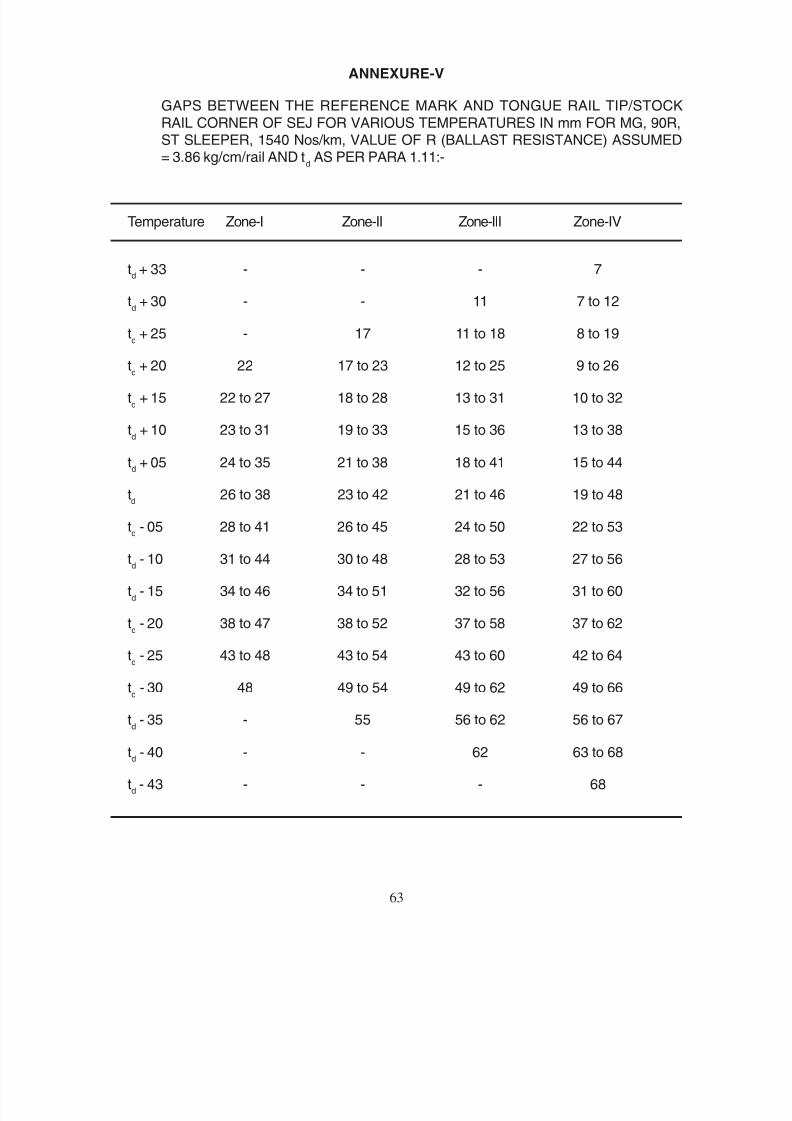
8/20/2019 lwrm
http://slidepdf.com/reader/full/lwrm 139/226
ANNEXURE-V
GAPS BETWEEN THE REFERENCE MARK AND TONGUE RAIL TIP/STOCK
RAIL CORNER OF SEJ FOR VARIOUS TEMPERATURES IN mm FOR MG, 90R,ST SLEEPER, 1540 Nos/km, VALUE OF R (BALLAST RESISTANCE) ASSUMED= 3.86 kg/cm/rail AND t
d AS PER PARA 1.11:-
Temperature Zone-I Zone-II Zone-III Zone-IV
td + 33 - - - 7
td + 30 - - 11 7 to 12
td + 25 - 17 11 to 18 8 to 19
td + 20 22 17 to 23 12 to 25 9 to 26
td + 15 22 to 27 18 to 28 13 to 31 10 to 32
td + 10 23 to 31 19 to 33 15 to 36 13 to 38
td + 05 24 to 35 21 to 38 18 to 41 15 to 44
td
26 to 38 23 to 42 21 to 46 19 to 48
td - 05 28 to 41 26 to 45 24 to 50 22 to 53
td - 10 31 to 44 30 to 48 28 to 53 27 to 56
td - 15 34 to 46 34 to 51 32 to 56 31 to 60
td - 20 38 to 47 38 to 52 37 to 58 37 to 62
td - 25 43 to 48 43 to 54 43 to 60 42 to 64
td - 30 48 49 to 54 49 to 62 49 to 66
td - 35 - 55 56 to 62 56 to 67
td - 40 - - 62 63 to 68
td - 43 - - - 68
63
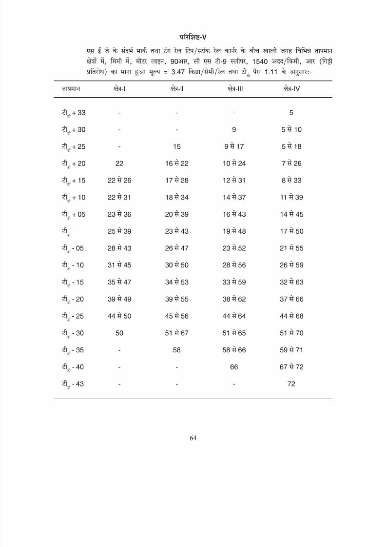
8/20/2019 lwrm
http://slidepdf.com/reader/full/lwrm 140/226
-V
90 -9 1540
3.47
1.11
-I -II -III -IV
+ 33 - - - 5
+ 30 - - 9 5 10
+ 25 - 15 9 17 5 18
+ 20 22 16 22 10 24 7 26
+ 15 22 26 17 28 12 31 8 33
+ 10 22 31 18 34 14 37 11 39
+ 05 23 36 20 39 16 43 14 45
25 39 23 43 19 48 17 50
- 05 28 43 26 47 23 52 21 55
- 10 31 45 30 50 28 56 26 59
- 15 35 47 34 53 33 59 32 63
- 20 39 49 39 55 38 62 37 66
- 25 44 50 45 56 44 64 44 68
- 30 50 51 67 51 65 51 70
- 35 - 58 58 66 59 71
- 40 - - 66 67 72
- 43 - - - 72
64
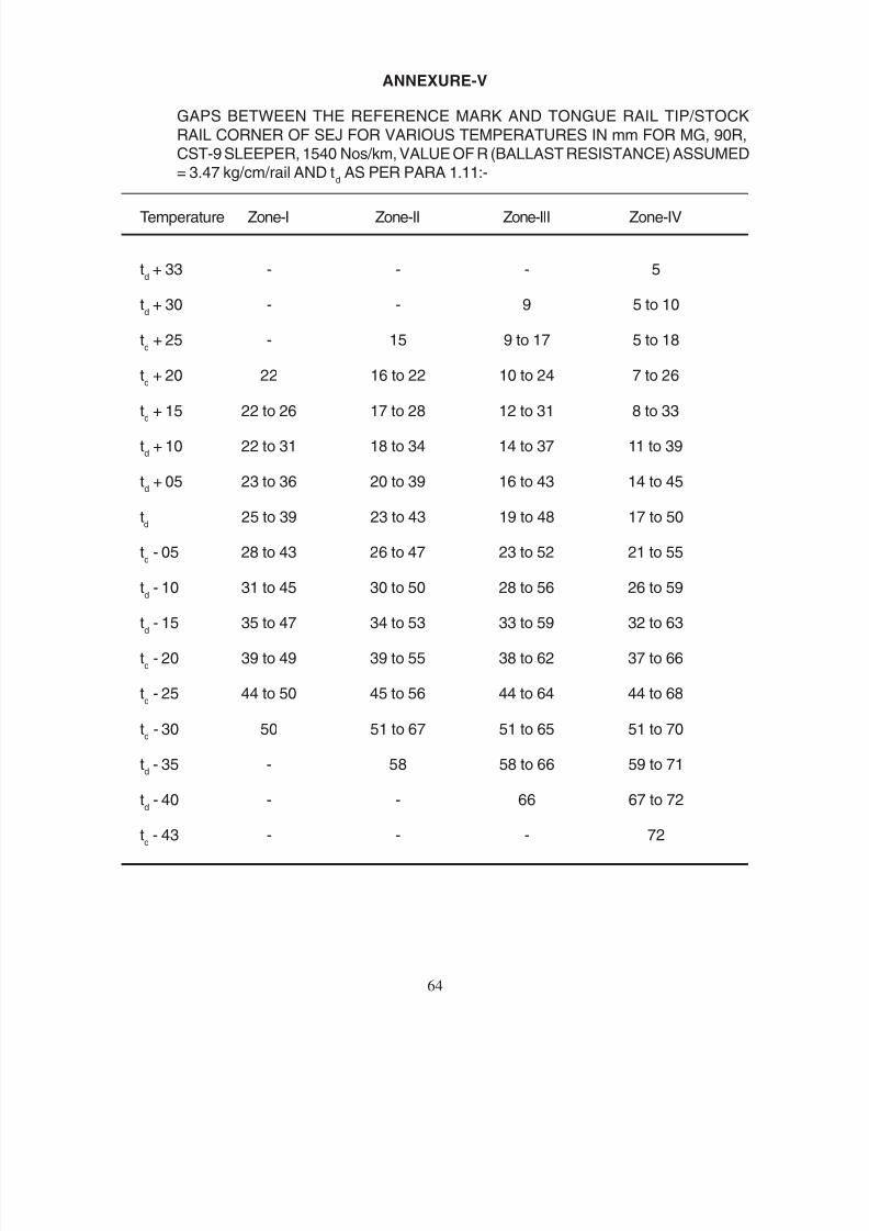
8/20/2019 lwrm
http://slidepdf.com/reader/full/lwrm 141/226
ANNEXURE-V
GAPS BETWEEN THE REFERENCE MARK AND TONGUE RAIL TIP/STOCK
RAIL CORNER OF SEJ FOR VARIOUS TEMPERATURES IN mm FOR MG, 90R,CST-9 SLEEPER, 1540 Nos/km, VALUE OF R (BALLAST RESISTANCE) ASSUMED= 3.47 kg/cm/rail AND t
d AS PER PARA 1.11:-
Temperature Zone-I Zone-II Zone-III Zone-IV
td + 33 - - - 5
td + 30 - - 9 5 to 10
td + 25 - 15 9 to 17 5 to 18
td
+ 20 22 16 to 22 10 to 24 7 to 26
td + 15 22 to 26 17 to 28 12 to 31 8 to 33
td + 10 22 to 31 18 to 34 14 to 37 11 to 39
td + 05 23 to 36 20 to 39 16 to 43 14 to 45
td
25 to 39 23 to 43 19 to 48 17 to 50
td - 05 28 to 43 26 to 47 23 to 52 21 to 55
td - 10 31 to 45 30 to 50 28 to 56 26 to 59
td - 15 35 to 47 34 to 53 33 to 59 32 to 63
td - 20 39 to 49 39 to 55 38 to 62 37 to 66
td - 25 44 to 50 45 to 56 44 to 64 44 to 68
td - 30 50 51 to 67 51 to 65 51 to 70
td - 35 - 58 58 to 66 59 to 71
td - 40 - - 66 67 to 72
td - 43 - - - 72
64

8/20/2019 lwrm
http://slidepdf.com/reader/full/lwrm 142/226
-V
75 1540
3.86
1.11
-I -II -III -IV
+ 33 - - - 11
+ 30 - - 14 11 15
+ 25 - 19 14 20 11 21
+ 20 23 19 24 15 26 12 27
+ 15 23 27 20 29 16 31 14 32
+ 10 24 31 21 33 18 35 16 37
+ 05 25 34 23 37 20 39 18 41
26 37 25 40 22 43 20 45
- 05 28 39 27 43 25 46 24 49
- 10 31 41 30 45 28 49 27 54
- 15 34 43 33 47 32 52 31 55
- 20 37 44 37 49 36 54 36 57
- 25 41 45 41 50 41 55 40 59
- 30 45 46 50 46 56 46 60
- 35 - 51 51 57 51 61
- 40 - - 57 58 61
- 43 - - - 62
65
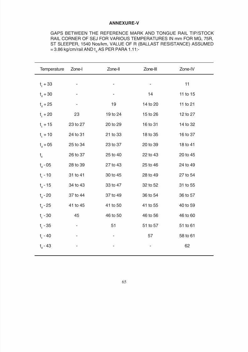
8/20/2019 lwrm
http://slidepdf.com/reader/full/lwrm 143/226
ANNEXURE-V
GAPS BETWEEN THE REFERENCE MARK AND TONGUE RAIL TIP/STOCK
RAIL CORNER OF SEJ FOR VARIOUS TEMPERATURES IN mm FOR MG, 75R,ST SLEEPER, 1540 Nos/km, VALUE OF R (BALLAST RESISTANCE) ASSUMED= 3.86 kg/cm/rail AND t
d AS PER PARA 1.11:-
Temperature Zone-I Zone-II Zone-III Zone-IV
td + 33 - - - 11
td + 30 - - 14 11 to 15
td + 25 - 19 14 to 20 11 to 21
td + 20 23 19 to 24 15 to 26 12 to 27
td + 15 23 to 27 20 to 29 16 to 31 14 to 32
td + 10 24 to 31 21 to 33 18 to 35 16 to 37
td + 05 25 to 34 23 to 37 20 to 39 18 to 41
td
26 to 37 25 to 40 22 to 43 20 to 45
td - 05 28 to 39 27 to 43 25 to 46 24 to 49
td - 10 31 to 41 30 to 45 28 to 49 27 to 54
td - 15 34 to 43 33 to 47 32 to 52 31 to 55
td - 20 37 to 44 37 to 49 36 to 54 36 to 57
td - 25 41 to 45 41 to 50 41 to 55 40 to 59
td - 30 45 46 to 50 46 to 56 46 to 60
td - 35 - 51 51 to 57 51 to 61
td - 40 - - 57 58 to 61
td - 43 - - - 62
65
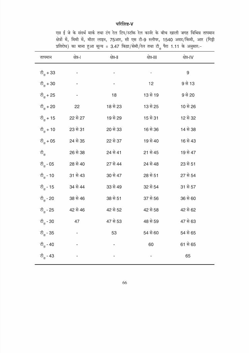
8/20/2019 lwrm
http://slidepdf.com/reader/full/lwrm 144/226
-V
75 -9 1540
3.47
1.11
-I -II -III -IV
+ 33 - - - 9
+ 30 - - 12 9 13
+ 25 - 18 13 19 9 20
+ 20 22 18 23 13 25 10 26
+ 15 22 27 19 29 15 31 12 32
+ 10 23 31 20 33 16 36 14 38
+ 05 24 35 22 37 19 40 16 43
26 38 24 41 21 45 19 47
- 05 28 40 27 44 24 48 23 51
- 10 31 43 30 47 28 51 27 54
- 15 34 44 33 49 32 54 31 57
- 20 38 46 38 51 37 56 36 60
- 25 42 46 42 52 42 58 42 62
- 30 47 47 53 48 59 47 63
- 35 - 53 54 60 54 65
- 40 - - 60 61 65
- 43 - - - 65
66

8/20/2019 lwrm
http://slidepdf.com/reader/full/lwrm 145/226
ANNEXURE-V
GAPS BETWEEN THE REFERENCE MARK AND TONGUE RAIL TIP/STOCK
RAIL CORNER OF SEJ FOR VARIOUS TEMPERATURES IN mm FOR MG, 75R,CST-9 SLEEPER, 1540 Nos/kms VALUE OF R (BALLAST RESISTANCE) ASSUMED= 3.47 kg/cm/rall AND t
d AS PER PARA 1.11:-
Temperature Zone-I Zone-II Zone-III Zone-IV
td + 33 - - - 9
td + 30 - - 12 9 to 13
td + 25 - 18 13 to 19 9 to 20
td
+ 20 22 18 to 23 13 to 25 10 to 26
td + 15 22 to 27 19 to 29 15 to 31 12 to 32
td + 10 23 to 31 20 to 33 16 to 36 14 to 38
td + 05 24 to 35 22 to 37 19 to 40 16 to 43
td
26 to 38 24 to 41 24 to 45 19 to 47
td - 05 28 to 40 27 to 44 24 to 48 23 to 51
td - 10 31 to 43 30 to 47 28 to 51 27 to 54
td - 15 34 to 44 33 to 49 32 to 54 31 to 57
td - 20 38 to 46 38 to 51 37 to 56 36 to 60
td - 25 42 to 46 42 to 52 42 to 58 42 to 62
td - 30 47 47 to 53 48 to 59 47 to 63
td - 35 - 53 54 to 60 54 to 65
td - 40 - - 60 61 to 65
td - 43 - - - 65
66
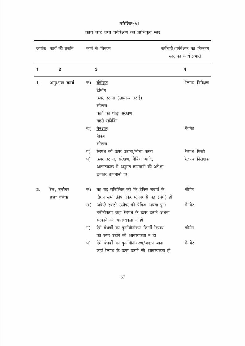
8/20/2019 lwrm
http://slidepdf.com/reader/full/lwrm 146/226
VI
1 2 3 4
1.
2.
67
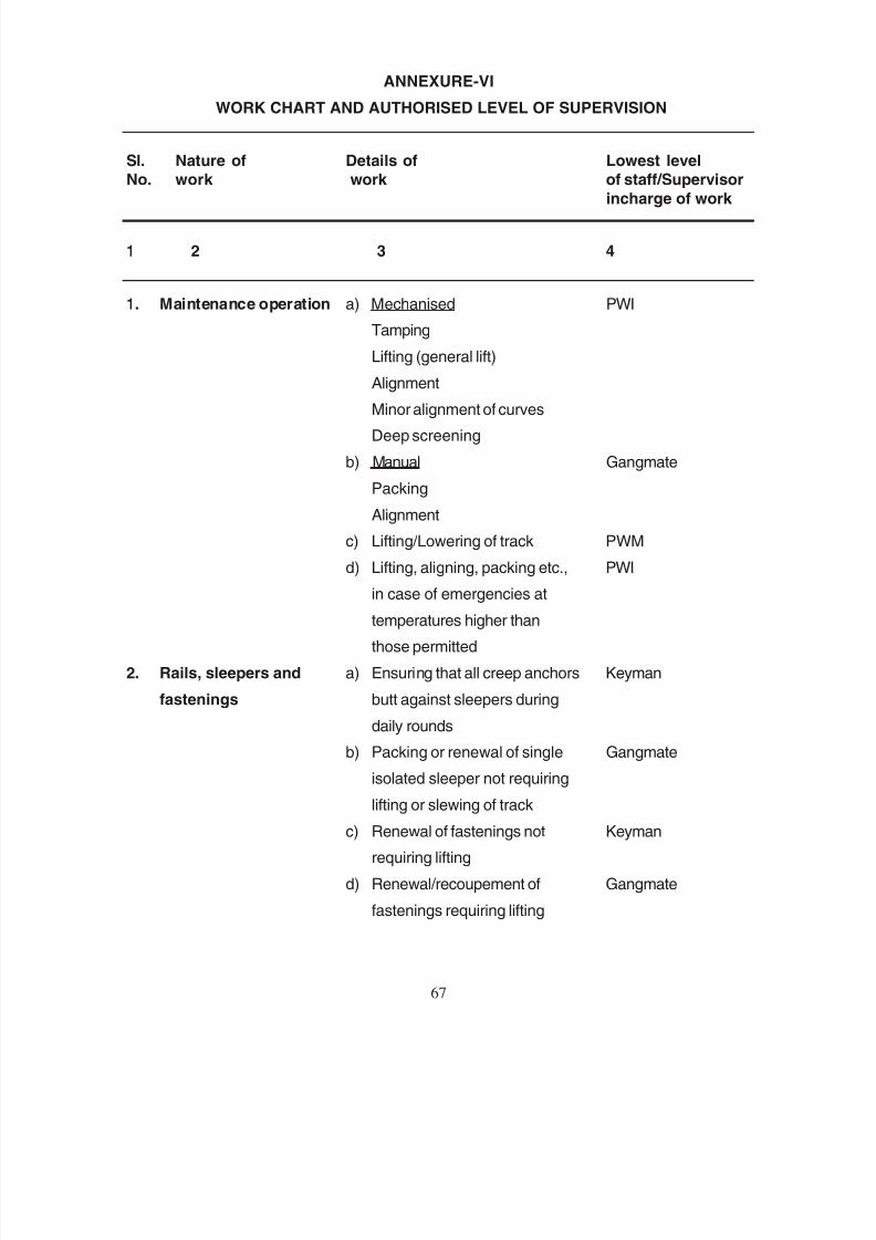
8/20/2019 lwrm
http://slidepdf.com/reader/full/lwrm 147/226
ANNEXURE-VI
WORK CHART AND AUTHORISED LEVEL OF SUPERVISION
Sl. Nature of Details of Lowest level
No. work work of staff/Supervisor
incharge of work
1 2 3 4
1. Maintenance operation a) Mechanised PWI
Tamping
Lifting (general lift)
AlignmentMinor alignment of curves
Deep screening
b) Manual Gangmate
Packing
Alignment
c) Lifting/Lowering of track PWM
d) Lifting, aligning, packing etc., PWI
in case of emergencies at
temperatures higher than
those permitted
2. Rails, sleepers and a) Ensuring that all creep anchors Keyman
fastenings butt against sleepers during
daily rounds
b) Packing or renewal of single Gangmate
isolated sleeper not requiring
lifting or slewing of track
c) Renewal of fastenings not Keyman
requiring lifting
d) Renewal/recoupement of Gangmate
fastenings requiring lifting
67
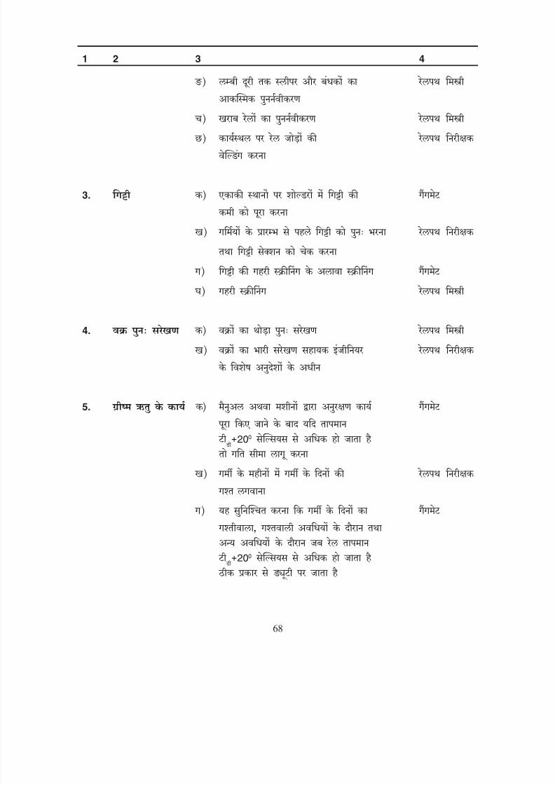
8/20/2019 lwrm
http://slidepdf.com/reader/full/lwrm 148/226
3.
4.
5.
200
200
68
1 2 3 4
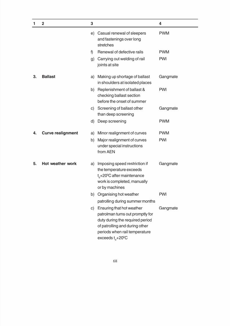
8/20/2019 lwrm
http://slidepdf.com/reader/full/lwrm 149/226
e) Casual renewal of sleepers PWM
and fastenings over long
stretches
f) Renewal of defective rails PWM
g) Carrying out welding of rail PWI
joints at site
3. Ballast a) Making up shortage of ballast Gangmate
in shoulders at isolated places
b) Replenishment of ballast & PWI
checking ballast section
before the onset of summerc) Screening of ballast other Gangmate
than deep screening
d) Deep screening PWM
4. Curve realignment a) Minor realignment of curves PWM
b) Major realignment of curves PWI
under special instructions
from AEN
5. Hot weather work a) Imposing speed restriction if Gangmate
the temperature exceeds
td+200C after maintenance
work is completed, manually
or by machines
b) Organising hot weather PWI
patrolling during summer months
c) Ensuring that hot weather Gangmate
patrolman turns out promptly for
duty during the required period
of patrolling and during other
periods when rail temperature
exceeds td+200C
68
1 2 3 4
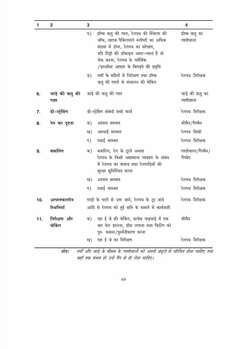
8/20/2019 lwrm
http://slidepdf.com/reader/full/lwrm 150/226
6.
7.
8.
9.
10.
11.
69
1 2 3 4
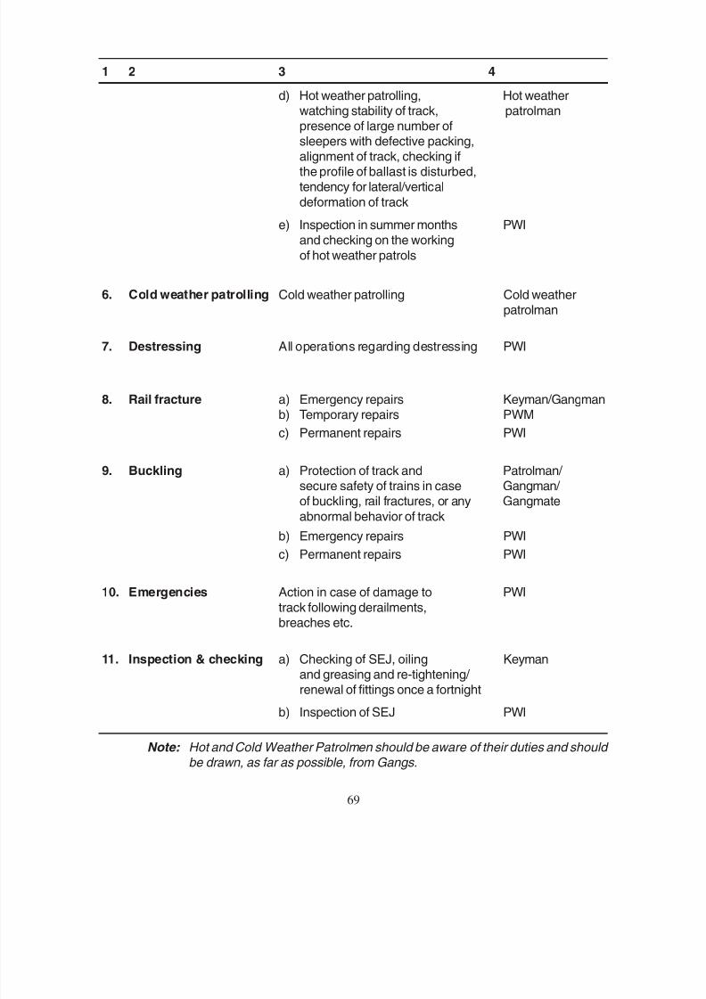
8/20/2019 lwrm
http://slidepdf.com/reader/full/lwrm 151/226
d) Hot weather patrolling, Hot weatherwatching stability of track, patrolmanpresence of large number ofsleepers with defective packing,
alignment of track, checking ifthe profile of ballast is disturbed,tendency for lateral/vertical
deformation of track
e) Inspection in summer months PWIand checking on the working
of hot weather patrols
6. Cold weather patrolling Cold weather patrolling Cold weather
patrolman
7. Destressing All operations regarding destressing PWI
8. Rail fracture a) Emergency repairs Keyman/Gangmanb) Temporary repairs PWM
c) Permanent repairs PWI
9. Buckling a) Protection of track and Patrolman/ secure safety of trains in case Gangman/ of buckling, rail fractures, or any Gangmate
abnormal behavior of track
b) Emergency repairs PWI
c) Permanent repairs PWI
10. Emergencies Action in case of damage to PWI
track following derailments,
breaches etc.
11. Inspection & checking a) Checking of SEJ, oiling Keymanand greasing and re-tightening/ renewal of fittings once a fortnight
b) Inspection of SEJ PWI
Note: Hot and Cold Weather Patrolmen should be aware of their duties and should be drawn, as far as possible, from Gangs.
69
1 2 3 4
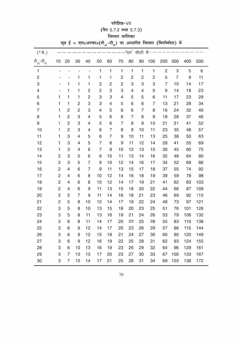
8/20/2019 lwrm
http://slidepdf.com/reader/full/lwrm 152/226
VII
5.7.2 5.7.3
x x
0
10 20 30 40 50 60 70 80 90 100 200 300 400 500
1 - - - - 1 1 1 1 1 1 2 3 5 6
2 - - 1 1 1 1 2 2 2 2 5 7 9 11
3 - 1 1 1 2 2 2 3 3 3 7 10 14 17
4 - 1 1 2 2 3 3 4 4 5 9 14 18 23
5 1 1 1 2 3 3 4 5 5 6 11 17 23 29
6 1 1 2 3 3 4 5 6 6 7 13 21 28 34
7 1 2 2 3 4 5 6 6 7 8 16 24 32 40
8 1 2 3 4 5 6 6 7 8 9 18 28 37 46
9 1 2 3 4 5 6 7 8 9 10 21 31 41 52
10 1 2 3 4 6 7 8 9 10 11 23 35 48 57
11 1 3 4 5 6 7 9 10 11 13 25 38 50 63
12 1 3 4 5 7 8 9 11 12 14 28 41 55 69
13 1 3 4 6 7 9 10 12 13 15 30 45 60 75
14 2 3 5 6 8 10 11 13 14 16 32 48 64 80
15 2 3 5 7 9 10 12 14 16 17 34 52 69 86
16 2 4 6 7 9 11 13 15 17 18 37 55 74 92
17 2 4 6 8 10 12 14 16 18 19 39 59 78 98
18 2 4 6 8 10 12 14 17 19 21 41 62 83 103
19 2 4 6 9 11 13 15 18 20 22 44 66 87 109
20 2 5 7 9 11 14 16 18 21 23 46 69 92 115
21 2 5 8 10 12 14 17 19 22 24 48 73 97 121
22 3 5 8 10 13 15 18 20 23 25 51 76 101 126
23 3 5 8 11 13 16 19 21 24 26 53 79 106 13224 3 6 8 11 14 17 20 22 25 28 55 83 110 138
25 3 6 9 12 14 17 20 23 26 29 57 86 115 144
26 3 6 9 12 15 18 21 24 27 30 60 90 120 149
27 3 6 9 12 16 19 22 25 28 31 62 93 124 155
28 3 6 10 13 16 19 23 26 29 32 64 96 129 161
29 3 7 10 13 17 20 23 27 30 33 67 100 133 167
30 3 7 10 14 17 21 25 28 31 34 69 103 138 172
70
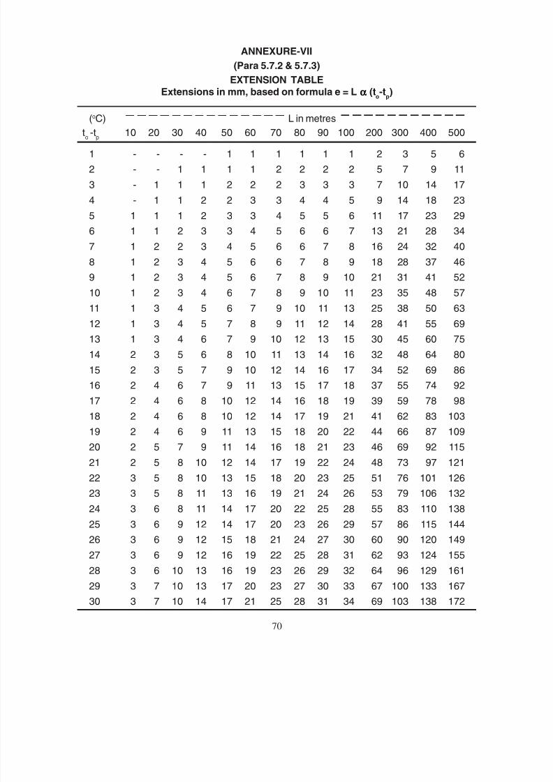
8/20/2019 lwrm
http://slidepdf.com/reader/full/lwrm 153/226
ANNEXURE-VII
(Para 5.7.2 & 5.7.3)
EXTENSION TABLE
Extensions in mm, based on formula e = L ααααα (to-t
p)
(o
C) L in metresto -t
p10 20 30 40 50 60 70 80 90 100 200 300 400 500
1 - - - - 1 1 1 1 1 1 2 3 5 6
2 - - 1 1 1 1 2 2 2 2 5 7 9 11
3 - 1 1 1 2 2 2 3 3 3 7 10 14 17
4 - 1 1 2 2 3 3 4 4 5 9 14 18 23
5 1 1 1 2 3 3 4 5 5 6 11 17 23 29
6 1 1 2 3 3 4 5 6 6 7 13 21 28 34
7 1 2 2 3 4 5 6 6 7 8 16 24 32 40
8 1 2 3 4 5 6 6 7 8 9 18 28 37 46
9 1 2 3 4 5 6 7 8 9 10 21 31 41 52
10 1 2 3 4 6 7 8 9 10 11 23 35 48 57
11 1 3 4 5 6 7 9 10 11 13 25 38 50 63
12 1 3 4 5 7 8 9 11 12 14 28 41 55 69
13 1 3 4 6 7 9 10 12 13 15 30 45 60 75
14 2 3 5 6 8 10 11 13 14 16 32 48 64 80
15 2 3 5 7 9 10 12 14 16 17 34 52 69 86
16 2 4 6 7 9 11 13 15 17 18 37 55 74 92
17 2 4 6 8 10 12 14 16 18 19 39 59 78 98
18 2 4 6 8 10 12 14 17 19 21 41 62 83 103
19 2 4 6 9 11 13 15 18 20 22 44 66 87 109
20 2 5 7 9 11 14 16 18 21 23 46 69 92 115
21 2 5 8 10 12 14 17 19 22 24 48 73 97 121
22 3 5 8 10 13 15 18 20 23 25 51 76 101 126
23 3 5 8 11 13 16 19 21 24 26 53 79 106 132
24 3 6 8 11 14 17 20 22 25 28 55 83 110 138
25 3 6 9 12 14 17 20 23 26 29 57 86 115 144
26 3 6 9 12 15 18 21 24 27 30 60 90 120 149
27 3 6 9 12 16 19 22 25 28 31 62 93 124 155
28 3 6 10 13 16 19 23 26 29 32 64 96 129 161
29 3 7 10 13 17 20 23 27 30 33 67 100 133 167
30 3 7 10 14 17 21 25 28 31 34 69 103 138 172
70

8/20/2019 lwrm
http://slidepdf.com/reader/full/lwrm 154/226
VIII
5.7.4
1.
1.11
2. 30
3. 5.6
4.
5.3(viii)( )) 5.7.2 (v)
5. 1.11
6.
20 20
71
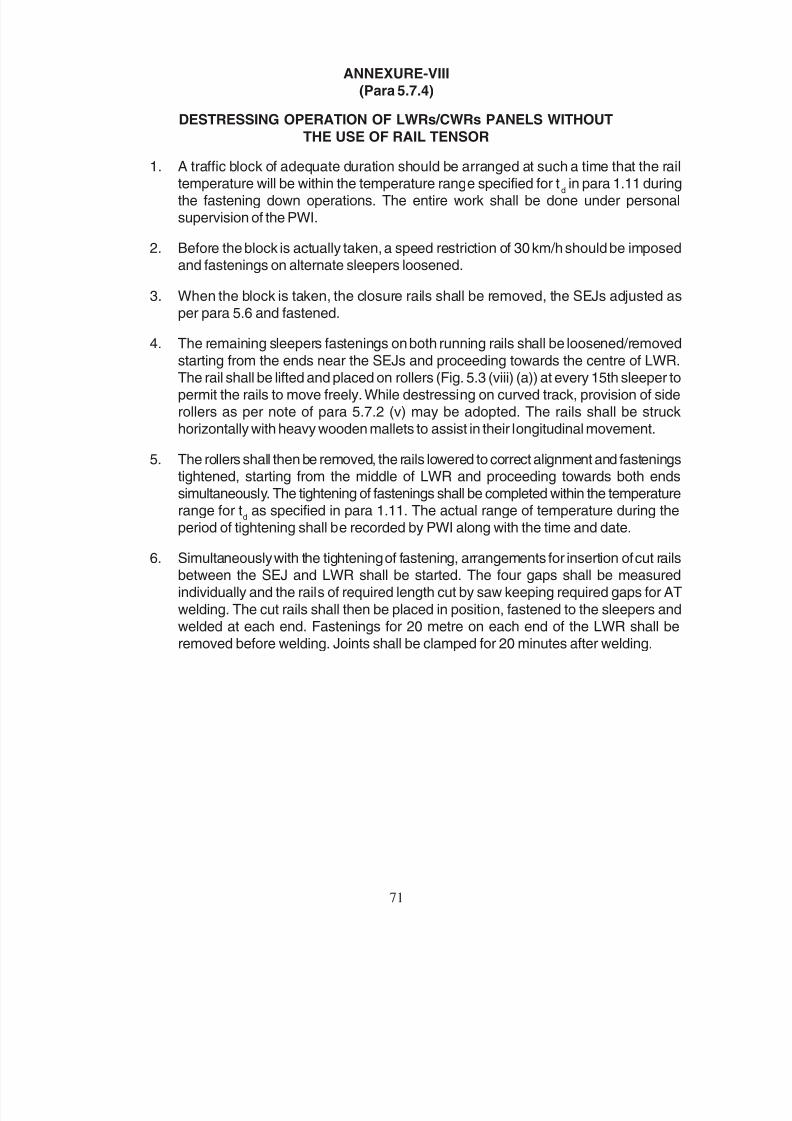
8/20/2019 lwrm
http://slidepdf.com/reader/full/lwrm 155/226
ANNEXURE-VIII
(Para 5.7.4)
DESTRESSING OPERATION OF LWRs/CWRs PANELS WITHOUT
THE USE OF RAIL TENSOR
1. A traffic block of adequate duration should be arranged at such a time that the railtemperature will be within the temperature range specified for t
d in para 1.11 during
the fastening down operations. The entire work shall be done under personalsupervision of the PWI.
2. Before the block is actually taken, a speed restriction of 30 km/h should be imposedand fastenings on alternate sleepers loosened.
3. When the block is taken, the closure rails shall be removed, the SEJs adjusted asper para 5.6 and fastened.
4. The remaining sleepers fastenings on both running rails shall be loosened/removed
starting from the ends near the SEJs and proceeding towards the centre of LWR.The rail shall be lifted and placed on rollers (Fig. 5.3 (viii) (a)) at every 15th sleeper topermit the rails to move freely. While destressing on curved track, provision of siderollers as per note of para 5.7.2 (v) may be adopted. The rails shall be struckhorizontally with heavy wooden mallets to assist in their longitudinal movement.
5. The rollers shall then be removed, the rails lowered to correct alignment and fasteningstightened, starting from the middle of LWR and proceeding towards both endssimultaneously. The tightening of fastenings shall be completed within the temperaturerange for t
d as specified in para 1.11. The actual range of temperature during the
period of tightening shall be recorded by PWI along with the time and date.
6. Simultaneously with the tightening of fastening, arrangements for insertion of cut railsbetween the SEJ and LWR shall be started. The four gaps shall be measuredindividually and the rails of required length cut by saw keeping required gaps for AT
welding. The cut rails shall then be placed in position, fastened to the sleepers andwelded at each end. Fastenings for 20 metre on each end of the LWR shall beremoved before welding. Joints shall be clamped for 20 minutes after welding.
71

8/20/2019 lwrm
http://slidepdf.com/reader/full/lwrm 156/226
IX
1.6
1. 1.6
2. I II 3 III IV 4 6.5 6.0
3. 1899 11599 .9 ( ) .9 ( )
4. 7.5
5. 12 1
6.
3
7.
8.
9.
150
150 3 12 241
72

8/20/2019 lwrm
http://slidepdf.com/reader/full/lwrm 157/226
72
ANNEXURE-IX
(Para 1.6)
INSTRUCTIONS FOR LAYING AND MAINTENANCE OF BUFFER
RAILS AT THE END OF LWRs/CWRs
1. Buffer Rails may be provided subject to conditions laid down in para 1.6.
2. In rail temperature zones I & II, 3 buffer rails, while in zones III & IV, 4 buffer railsshall be provided. On BG, buffer rails would be 6.5 metre long and while for MG
6.0 metre long.
3. Buffer rails may be laid on PRC sleepers with J-clips or on wooden sleeperswith M.S. canted bearing plate and rail screws. Standard fishplates shall be
used at the joints. However, for effective tightness of bolts, bolt to drawing No.T-11599 may be used in lieu of that of drawing No. RDSO/T-1899. The number,type and spacing of sleepers for buffer rail assembly shall be as indicated inFig. A.9(a) and Fig. A.9(b) for BG & MG respectively.
4. A gap of 7.5 mm shall be provided at each of fishplated joints of buffer rail assemblyat the time of initial laying/destressing.
5. The fishplated joints of buffer rails shall be accurately fabricated. In case
pre-drilled rails and standard fishplates are used, the dimensions and squarenessof rail ends shall conform to the tolerances stipulated in the specificationsIRS T-12 for rails and IRS T-1 for fishplates. Holes drilled at site shallalso conform to the above specifications. All holes in buffer rails shall bechamfered.
6. In the case of buffer rails laid between conventional track and LWR, the former shallbe box-anchored for 3 rail lengths.
7. Special and prompt attention shall be paid to the alignment and levels oftrack in the buffer rail portions. Buffer rails shall be free of kinks and hogs. Theinspecting officials shall critically examine the buffer rails each time they passover the same.
8. The fish-bolts shall be kept tight at all times.
9. Joints in buffer rails shall be lubricated twice in a year when the rail temperatureis between t
d+150C and t
d-150C and when the average gap value is between
3 mm and 12 mm. The rail ends shall be examined at the time of lubrication for
any crack around bolt-holes. Bent fish-bolts, if any, shall be replaced. Generalinstructions for lubricating fishplated joints as laid down in para 241 of IndianRailways Permanent Way Manual shall be followed.

8/20/2019 lwrm
http://slidepdf.com/reader/full/lwrm 158/226
10.
8.1.5
III
IV
300
300 15
i)
ii)
iii)
iv)
I II
250
250
7.5
11.
73

8/20/2019 lwrm
http://slidepdf.com/reader/full/lwrm 159/226
73
10. a) The individual gaps in the buffer rail portion may vary and no attempt toequalise them need be made.
b) The gap of buffer rails shall be measured as per schedule laid down forSEJs as per para 8.1.5. In addition to above schedule, the gaps shallalso be carefully inspected during regular inspections. In rail temperature
zones III & IV, if all the gaps are found to close at a temperature lowerthan td + 300C and/or to fully open to 15 mm at a temperature higher than
td - 300C, it indicates one or more of the following:-
i) Defective initial gaps
ii) Inadequate packing in breathing length
iii) Relative movement of rail over sleepers in breathing lengths
iv) Creep of LWR
For rail temperature zones I & II the lower limit of temperature for gapclosing and the upper limit of temperature for fully opening of gaps shallbe taken as t
d + 250C and t
d - 250C.
c) Rectification shall be done by destressing the LWRs/CWRs and byrestoring initial gaps as 7.5 mm. Breathing lengths shall be well packed.
Other remedial measures for proper functioning of LWRs/CWRs will alsobe taken.
11. Details of buffer rails and gap measurement of fishplated joints shall be recordedat the time of initial laying/subsequent inspections as per proforma given below.

8/20/2019 lwrm
http://slidepdf.com/reader/full/lwrm 160/226
1.
2.
3.
i)
ii)
i)
ii) 4.
5.
i)
ii) 3.6
iii) 3.6
iv) 7.2
6.
7.
74
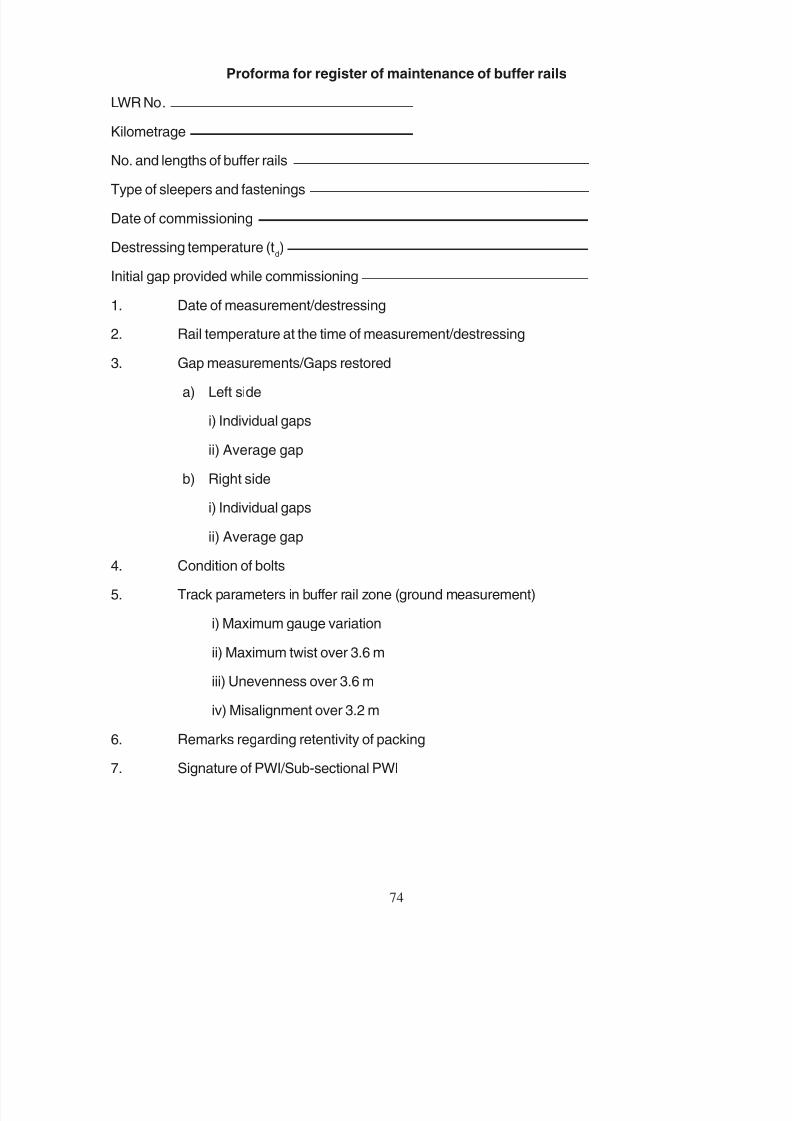
8/20/2019 lwrm
http://slidepdf.com/reader/full/lwrm 161/226
74
Proforma for register of maintenance of buffer rails
LWR No.
Kilometrage
No. and lengths of buffer rails
Type of sleepers and fastenings
Date of commissioning
Destressing temperature (td)
Initial gap provided while commissioning
1. Date of measurement/destressing
2. Rail temperature at the time of measurement/destressing
3. Gap measurements/Gaps restored
a) Left side
i) Individual gaps
ii) Average gap
b) Right side
i) Individual gaps
ii) Average gap
4. Condition of bolts
5. Track parameters in buffer rail zone (ground measurement)
i) Maximum gauge variation
ii) Maximum twist over 3.6 m
iii) Unevenness over 3.6 m
iv) Misalignment over 3.2 m
6. Remarks regarding retentivity of packing
7. Signature of PWI/Sub-sectional PWI

8/20/2019 lwrm
http://slidepdf.com/reader/full/lwrm 162/226
-X 9.1.2 (i)
200
1.
i) 2
ii)
2.
2
1
10 1
3.
100
100
75

8/20/2019 lwrm
http://slidepdf.com/reader/full/lwrm 163/226
75
ANNEXURE-X A
(Para 9.1.2 (i))
HOT WEATHER PATROLLING
Period for hot weather patrolling shall be laid down by the Chief Engineer
for each section and patrol charts prepared where necessary. Patrolling shallbe organised by PWI accordingly. In addition, the PWI/PWM and the Gangmate shall
be vigilant during summer and on hot days. Patrolling will also be introduced, whenthe rail temperature rises above t
d+200C. Following general guidelines may be
followed for issuing detailed guidelines by the Chief Engineer:-
1. Hot weather patrolling will be carried out as follows:-
i) On single line or where only one road in a double line section is having LWR/CWR- One patrolman for 2 km.
ii) On double line section when LWR/CWR exist on both roads - One patrolman for1 km length of UP and DN road. The beats of each hot weather patrolman will thusbe restricted to 2 km.
2. The hot weather patrolman should always carry the following equipments:-
HS Flags - Red 2
Staff for Flags 1
Detonators 10
Canne-a-boule 1
3. Duties of hot weather patrolman are as follows:-
He will walk over his beat slowly over one rail in one direction and on the other rail inthe return direction. On double lines, he will repeat this procedure alternately on UPand DN tracks. He will be vigilant and look out for kinks in the rail especially duringthe hottest part of the days. When a kink is observed, he shall immediately examineat least 100 sleepers ahead and in the rear of the kink for any floating condition oftrack. He should meticulously sound each and every sleeper, 100 sleepers on eitherside of the kink, to determine any floating condition. The sounding will be done by
dropping a canne-a-boule on each end of the sleeper to determine the extent of voidunder the sleeper. Should the sounding reveal a floating condition, under which abuckle may be anticipated or the patrolman has detected actual buckling of track, hewill take immediate steps to protect the affected portion by display of hand signalsas per rules in force. After protecting the track, the patrolman will arrange to advisethe Gangmate, PWM, PWI of his apprehension of a buckle/actual buckle.

8/20/2019 lwrm
http://slidepdf.com/reader/full/lwrm 164/226
4. 100
76

8/20/2019 lwrm
http://slidepdf.com/reader/full/lwrm 165/226
76
4. The Gangmate on receipt of advice of a danger of buckle, will proceed tothe site quickly with all available men. On arrival at site, he will first ensureprotection of affected portion. He should then inspect the condition of track100 m on either side of this suspected zone and commence heaping of surplusballast, if available, on the shoulders and upto the rail head and keep on
compacting the ballast with available tool. No attempt should be made to
slew or align the track or disturb the existing ballast section. The mateshould continue to remain at site till the arrival of P.Way Mistry/PWI. The railtemperature will also be noted by one of these officials at the place of apprehended/ actual buckle. The rail facing the sun will be covered upto the level of railhead on the outside by ballast or leaves etc. to bring down the temperature of
the rail.

8/20/2019 lwrm
http://slidepdf.com/reader/full/lwrm 166/226
-X 9.1.2 (ii)
-300
1.
i) 2
ii)
iii)
2.
10
3.
77

8/20/2019 lwrm
http://slidepdf.com/reader/full/lwrm 167/226
77
ANNEXURE-X B
( Para 9.1.2 (ii) )
COLD WEATHER PATROLLING
Cold weather patrolling shall be introduced when rail temperature is less thantd
- 300C. Period and section where cold weather patrolling is to be done shall be laiddown by the Chief Engineer and patrol charts prepared where necessary. Patrolling
shall be organised by PWI accordingly. Following guidelines may be followed forissuing detailed guidelines by the Chief Engineer.
1. Cold weather patrolling shall be carried out as follows:-
i) On single line or where only one road in a double section is havingLWR/CWR - One patrolman for two kilometre.
ii) On double line section when LWR/CWR rest on both road - One patrolmanfor one kilometre length of UP and DN road.
iii) Changes in beat length and man power deployment as given above iffound necessary, may be decided by the Chief Engineer depending onprevailing local conditions, frequency of train service, weather conditionsetc.
2. Cold weather patrolman should carry the following equipments: -
a) 10 fog signals in a tin case
b) Two tri-colour hand signal lamps
c) One match box
d) Two red flags and one green flag
e) One three-cell electric torch
f) One staff
g) Number plate
3. Duties of cold weather patrolman are as follows:-
He will walk over his beat slowly along one rail in one direction and on theother rail in the return direction. On double line, he will repeat this procedurealternately on UP and DN tracks. He will be vigilant and look out for rail/weld
failure. He will also notice the gaps at SEJs if they fall in his beat. In case henotices a rail/weld failure or gap at SEJ becomes more than the designedmaximum gap, he will take immediate action to suspend the traffic and protectthe line. After protecting the track the patrolman will arrange to report to Keyman/ Gangmate/PWM/ PWI, who shall arrange for making emergency repairs to passthe traffic immediately.
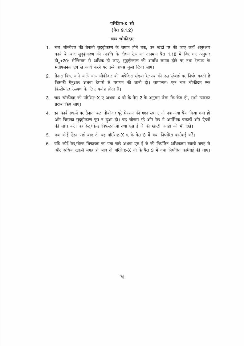
8/20/2019 lwrm
http://slidepdf.com/reader/full/lwrm 168/226
-X 9.1.2
1.
1.18
200
2.
3. X X 2
4.
5. X 3
6. X 3
78
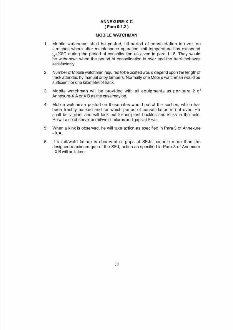
8/20/2019 lwrm
http://slidepdf.com/reader/full/lwrm 169/226
78
ANNEXURE-X C
( Para 9.1.2 )
MOBILE WATCHMAN
1. Mobile watchman shall be posted, till period of consolidation is over, onstretches where after maintenance operation, rail temperature has exceededtd+200C during the period of consolidation as given in para 1·18. They would
be withdrawn when the period of consolidation is over and the track behavessatisfactorily.
2. Number of Mobile watchman required to be posted would depend upon the length of
track attended by manual or by tampers. Normally one Mobile watchman would besufficient for one kilometre of track.
3. Mobile watchman will be provided with all equipments as per para 2 ofAnnexure-X A or X B as the case may be.
4. Mobile watchman posted on these sites would patrol the section, which hasbeen freshly packed and for which period of consolidation is not over. Heshall be vigilant and will look out for incipient buckles and kinks in the rails.He will also observe for rail/weld failures and gaps at SEJs.
5. When a kink is observed, he will take action as specified in Para 3 of Annexure- X A.
6. If a rail/weld failure is observed or gaps at SEJs become more than thedesigned maximum gap of the SEJ, action as specified in Para 3 of Annexure- X B will be taken.
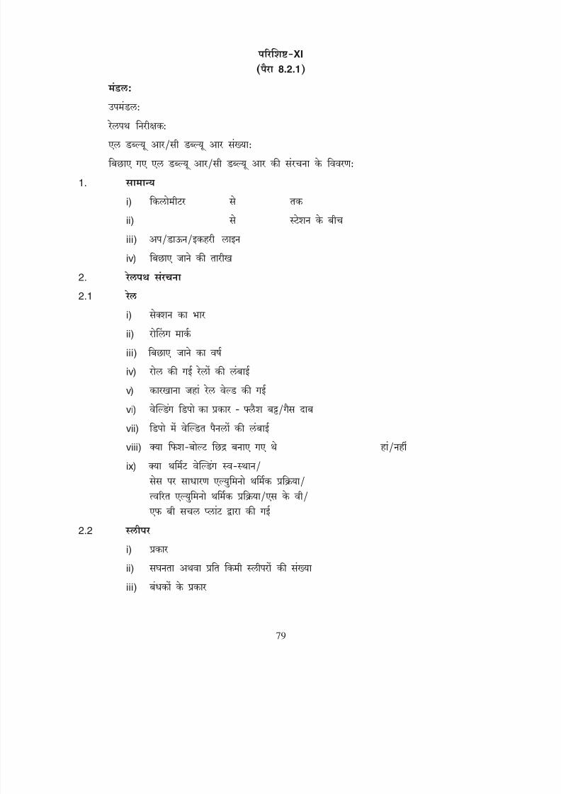
8/20/2019 lwrm
http://slidepdf.com/reader/full/lwrm 170/226
XI
8.2.1
1.
i)
ii)
iii)
iv)
2.
2.1
i)
ii)
iii)
iv) v)
vi)
vii)
viii)
ix)
2.2
i)
ii)
iii)
79

8/20/2019 lwrm
http://slidepdf.com/reader/full/lwrm 171/226
79
ANNEXURE - XI
(Para 8.2.1)
DIVISION:
SUB - DIVISION:
PWI:
LWR/CWR No.:
DETAILS OF STRUCTURE OF LWR/CWR AS LAID:
1. GENERAL
i) Kilometers to
ii) Between stations and
iii) Up/Down/Single line
iv) Date of laying
2. TRACK STRUCTURE
2.1 Rails
i) Sectional weight
ii) Rolling mark
iii) Year of laying
iv) Length of rails as rolled
v) Plant where rails welded
vi) Types of depot welding - Flash Butt/Gas pressure
vii) Length welded into panels at depot
viii) Whether fish-bolt holes provided Yes/No
(ix) Thermit welding done in-situ/on cessby ordinary alumino-thermic process/
quick alumino-thermic process/SKV/ FB by Mobile plant
2.2 Sleepers
i) Type
ii) Density or No. per km.
iii) Type of fastenings

8/20/2019 lwrm
http://slidepdf.com/reader/full/lwrm 172/226
iv)
v)
vi)
2.3
i)
ii)
iii)
2.4
i)
ii)
iii)
iv)
v)
vi)
2.5
i)
ii) iii)
iv)
2.6
3.
i)
ii)
iii)
iv)
80
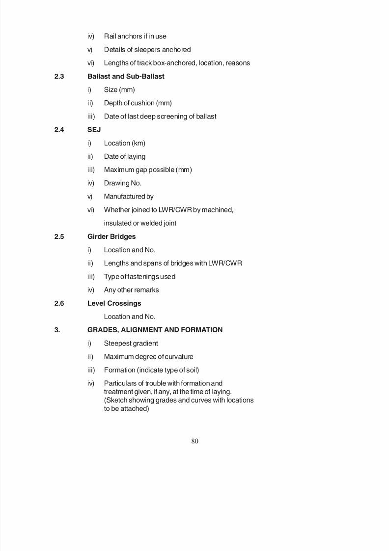
8/20/2019 lwrm
http://slidepdf.com/reader/full/lwrm 173/226
80
iv) Rail anchors if in use
v) Details of sleepers anchored
vi) Lengths of track box-anchored, location, reasons
2.3 Ballast and Sub-Ballast
i) Size (mm)
ii) Depth of cushion (mm)
iii) Date of last deep screening of ballast
2.4 SEJ
i) Location (km)
ii) Date of laying
iii) Maximum gap possible (mm)iv) Drawing No.
v) Manufactured by
vi) Whether joined to LWR/CWR by machined,
insulated or welded joint
2.5 Girder Bridges
i) Location and No.
ii) Lengths and spans of bridges with LWR/CWR
iii) Type of fastenings used
iv) Any other remarks
2.6 Level Crossings
Location and No.
3. GRADES, ALIGNMENT AND FORMATION
i) Steepest gradientii) Maximum degree of curvature
iii) Formation (indicate type of soil)
iv) Particulars of trouble with formation andtreatment given, if any, at the time of laying.(Sketch showing grades and curves with locations
to be attached)
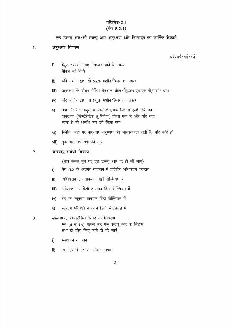
8/20/2019 lwrm
http://slidepdf.com/reader/full/lwrm 174/226
XII
8.2.1
1.
i)
ii)
iii)
iv)
v)
vi)
vii)
2.
i) 5.2
ii)
iii)
iv)
v)
3. (i) (iv)
i)
ii)
81
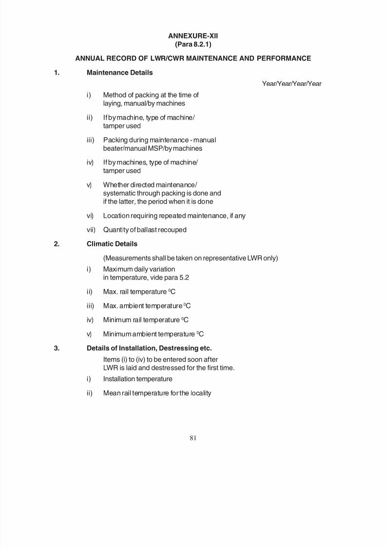
8/20/2019 lwrm
http://slidepdf.com/reader/full/lwrm 175/226
81
ANNEXURE-XII
(Para 8.2.1)
ANNUAL RECORD OF LWR/CWR MAINTENANCE AND PERFORMANCE
1. Maintenance Details
Year/Year/Year/Yeari) Method of packing at the time of
laying, manual/by machines
ii) If by machine, type of machine/ tamper used
iii) Packing during maintenance - manual
beater/manual MSP/by machines
iv) If by machines, type of machine/
tamper used
v) Whether directed maintenance/ systematic through packing is done andif the latter, the period when it is done
vi) Location requiring repeated maintenance, if any
vii) Quantity of ballast recouped
2. Climatic Details
(Measurements shall be taken on representative LWR only)
i) Maximum daily variationin temperature, vide para 5.2
ii) Max. rail temperature 0C
iii) Max. ambient temperature 0C
iv) Minimum rail temperature 0C
v) Minimum ambient temperature 0C
3. Details of Installation, Destressing etc.
Items (i) to (iv) to be entered soon afterLWR is laid and destressed for the first time.
i) Installation temperature
ii) Mean rail temperature for the locality
8/20/2019 lwrm
http://slidepdf.com/reader/full/lwrm 176/226
82
iii)
iv)
v)
4.
i)
ii)
iii)
iv)
v)
vi)
5.
i)

8/20/2019 lwrm
http://slidepdf.com/reader/full/lwrm 177/226
82
Year/Year/Year/Year
iii) Temperature at the time of destressing td
iv) Reasons for carrying out the destressing
v) Subsequent destressing done - temperature and date4. Unusual Occurrences
i) Rail fractures
ii) Buckling (Location and reasons for buckling)
iii) Replacement of components in SEJ assembly
a) Fastenings
b) Bolts
c) Sleepers
d) Longitudinal ties
e) MS bracket
f) Chairs
g) Rubber pads
h) Tongue rails
i) Stock rails
iv) Derailments and accidents on the
LWR/CWR portion(give km of the affected portion)
v) Replacement of sleepers (give kmand the number of sleepers replaced
and reasons)
vi) Replacement of rails(indicate length, km and reasons)
5. FORMATION
i) Any trouble subsequent to layingand the treatment given
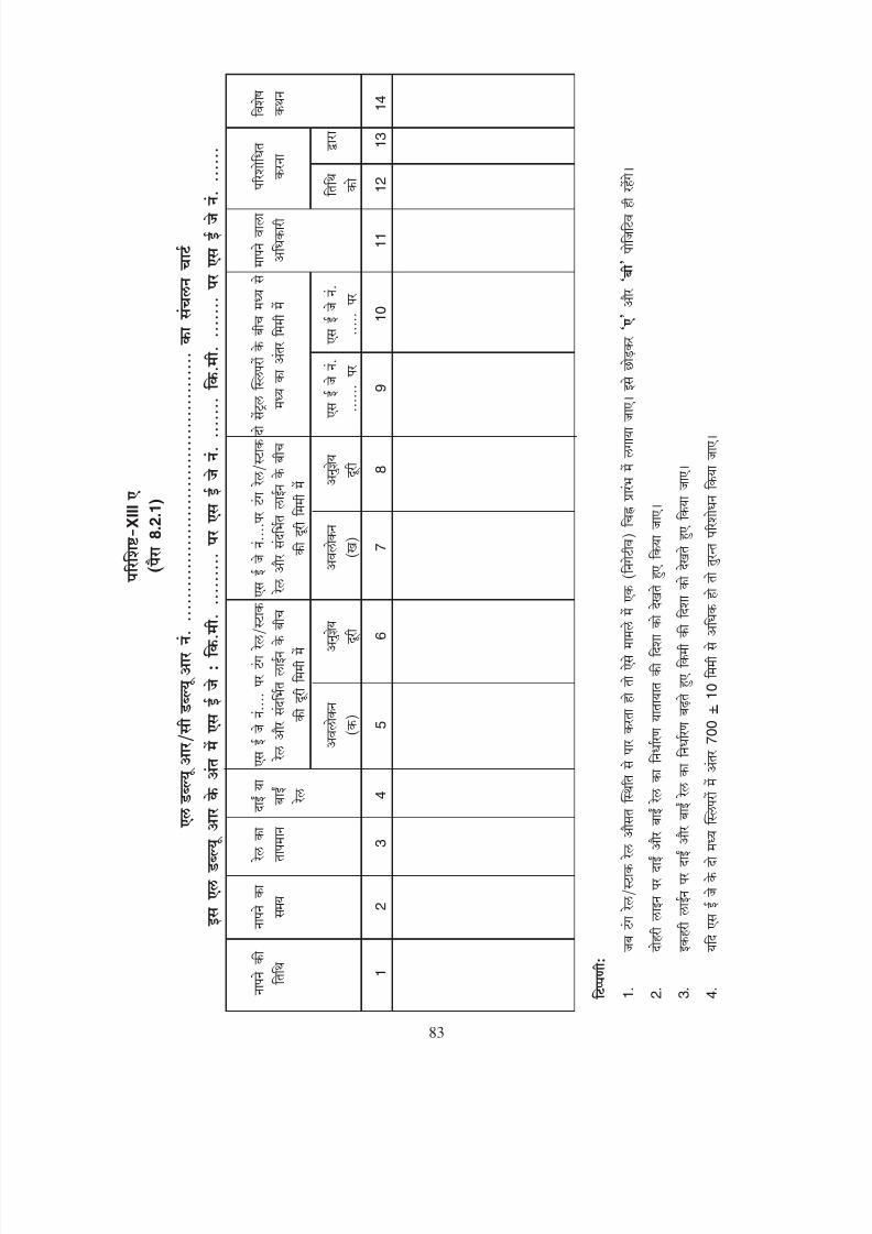
8/20/2019 lwrm
http://slidepdf.com/reader/full/lwrm 178/226
83
X I I I
8 . 2 . 1 )
1
2
3
4
5
6
7
8
9
1 0
1 1
1 2
1 3
1 4
1 .
2 .
3 .
4 .
7 0 0 + 1 0

8/20/2019 lwrm
http://slidepdf.com/reader/full/lwrm 179/226
A N N E X U R E - X I I I A
( P a r a 8 . 2 . 1 )
C H A R T O F M O V
E M E N T O F L W R / C W R N o .
S E J s
a t t h e e n d s o f t h i s L W R :
S E J N o .
a t k m
; S E J N o .
a t k m
D a t e
T i m e
R a i l
R i g h t
D i s t a n c e ( m m ) b e t w e e n
D
i s t a n c e ( m m ) b e t w e e n
C / C s p
a c i n g ( m m )
M e a s u r e d R e c t i f i c a t i o n
R e m a r k s
o f m e
a s -
o f m e a s -
T e m p .
o r
t o n g u e / s t o c k r a i l &
t o n g u e / s t o c k r a i l &
b e t w e
e n t h e t w o
b y
c a r r i e
d o u t
u r e m
e n t
u r e m e n t
L e f t
r e f e r e n c e l i n e
r e f e r e n c e l i n e
c e n t r a l s l e e p e r s
R a i l
a t S E J N o . . . . . . . .
a t S E J N o . . . . . . . .
O b s e r v e d
P e r m i s s i b l e
O b
s e r v e d
P e r m i s s i b l e
A t S E
J
A t S E J
O n d a
t e
B y
( a )
r a n g e
( b )
r a n g e
N o . . . . . . .
N o . . . . . . .
1
2
3
4
5
6
7
8
9
1 0
1 1
1 2
1 3
1 4
N o t e
:
1 .
( a ) a n d ( b ) w i l l a l m o s t a l w a y s b e p o s i t i v e , e x c e p t w h e n t o n g u
e / s t o c k r a i l c r o s s e s m e a n p o s i t i o n . I n s u c h a c a s e , a ( - v e ) s i g
n w i l l b e p r e f i x e d .
2 .
L e f t a n d r i g h t r a i l s o n d o u b l e l i n e s a r e d e t e r m i n e d l o o k i n g i n t h e d i r e c t i o n o f t r a f f i c .
3 .
L e f t a n d r i g h t r a i l s o n s i n g l e l i n
e s a r e d e t e r m i n e d , l o o k i n g i n t h e d i r e c t i o n o f i n c r e a s i n g k i l o m e t r a g e .
4 .
I f s p a c i n g o f 2 c e n t r a l s l e e p e r s o f S E J d i f f e r b y m o r e t h a n 7 0 0 + 1 0 m m , i m m e d i a t e r e c t i f i c a
t i o n w i l l b e m a d e .
83
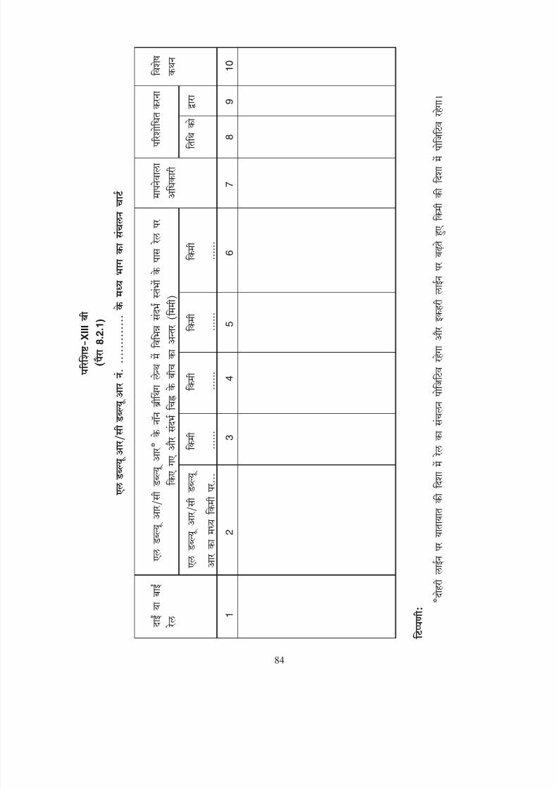
8/20/2019 lwrm
http://slidepdf.com/reader/full/lwrm 180/226
X I I I
8 . 2 . 1 )
1
2
3
4
5
6
7
8
9
1 0
84

8/20/2019 lwrm
http://slidepdf.com/reader/full/lwrm 181/226
A N N E X U R E - X I I I B
( P a r a 8 . 2 . 1 )
C H A R T
O F M O V E M E N T I N C E N T R
A L P O R T I O N O F L W R / C W R N o . . . . . . . . . . . . . . . . . . . . . .
D i s t a n c e ( m m ) b e t w e e n R e f . m a r k & m a r k o n R a i l a t
M e a s u r e d
R e c t i f i c a t i o n
R e m a r k s
v a r i o u s
R e f . P i l l a r s i n n o n - B . L . o f L W
R / C W R *
b y
c a r r i e d o u t
R i g h t o r
C e n t r e o f L W R / C W
R
O n d a t e
B y
L e
f t R a i l
a t k m . . . . . . . .
k m . . . . . . . . . . .
k m . . . . . . .
. . . .
k m . . . . . . . . . . .
k m . . . . . . . . . . .
1
2
3
4
5
6
7
8
9
1 0
N o t e
:
* M o v e m e n t o f r a i l s h a l l b e p o s i t i v e i n t h e d i r e c t i o n
o f t r a f f i c o n d o u b l e l i n e s a n
d i n t h e d i r e c t i o n o f h e a v i e r t r a f f i c o n s i n g l e
l i n e s w h i c h s h a l l b e s p e c i f i e d .
84

8/20/2019 lwrm
http://slidepdf.com/reader/full/lwrm 182/226
85
XIV
9.3
1.
2
2.
3.
4.
5.
6.
7.
8.
200
9.
10.
11.
12.
13.
14.
15.
16.
100
17.
200
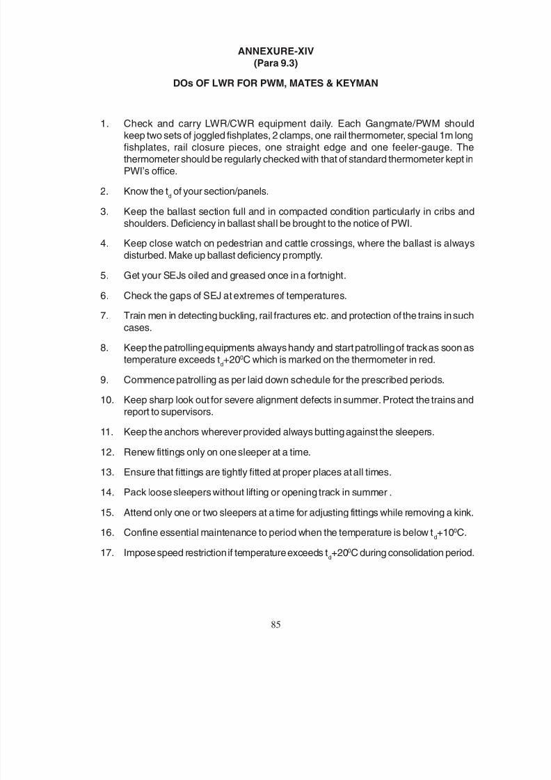
8/20/2019 lwrm
http://slidepdf.com/reader/full/lwrm 183/226
85
ANNEXURE-XIV
(Para 9.3)
DOs OF LWR FOR PWM, MATES & KEYMAN
1. Check and carry LWR/CWR equipment daily. Each Gangmate/PWM shouldkeep two sets of joggled fishplates, 2 clamps, one rail thermometer, special 1m longfishplates, rail closure pieces, one straight edge and one feeler-gauge. Thethermometer should be regularly checked with that of standard thermometer kept inPWI’s office.
2. Know the td of your section/panels.
3. Keep the ballast section full and in compacted condition particularly in cribs andshoulders. Deficiency in ballast shall be brought to the notice of PWI.
4. Keep close watch on pedestrian and cattle crossings, where the ballast is alwaysdisturbed. Make up ballast deficiency promptly.
5. Get your SEJs oiled and greased once in a fortnight.
6. Check the gaps of SEJ at extremes of temperatures.
7. Train men in detecting buckling, rail fractures etc. and protection of the trains in such
cases.
8. Keep the patrolling equipments always handy and start patrolling of track as soon astemperature exceeds t
d+200C which is marked on the thermometer in red.
9. Commence patrolling as per laid down schedule for the prescribed periods.
10. Keep sharp look out for severe alignment defects in summer. Protect the trains andreport to supervisors.
11. Keep the anchors wherever provided always butting against the sleepers.
12. Renew fittings only on one sleeper at a time.
13. Ensure that fittings are tightly fitted at proper places at all times.
14. Pack loose sleepers without lifting or opening track in summer .
15. Attend only one or two sleepers at a time for adjusting fittings while removing a kink.
16. Confine essential maintenance to period when the temperature is below td+100C.
17. Impose speed restriction if temperature exceeds td+200C during consolidation period.
8/20/2019 lwrm
http://slidepdf.com/reader/full/lwrm 184/226
86
18.
19.
20.
21. 9
22. (i) (ii) (iii) (iv) (v) (vi)
23.
24.
1.
2.
3.
4.
5. 30 30
6. 20,000
7. 30
8. 15
9. 30
10.
11.
12. 50
8/20/2019 lwrm
http://slidepdf.com/reader/full/lwrm 185/226
86
18. Pay special attention to SEJs, breathing lengths, curves, approaches to levelcrossings, unballasted bridges, horizontal and vertical curves.
19. Keep the rail thermometer with proper markings with limiting temperature rangesthereon in proper working order. Learn the limits of temperature restrictions asmarked on thermometers for various operations.
20. Check that reference posts at SEJ and at centre of LWR/CWR are correctlymaintained.
21. Pay special attention for crib and shoulder packing of ballast on CST-9 road.
22. Learn the six items (i) missing and loose fastenings, (ii) shortage of ballast,(iii) misalignment, (iv) slewing, (v) lifting (vi) improper packing, about which youshould be very careful to avoid buckling.
23. Learn what to do when there is buckling or fracture in the track.
24. Ensure that all bridges and its approaches have all fittings at all times and are regularly
tightened.
DON’Ts of LWR for PWM, Mates & Keyman
1. Do not touch the track unnecessarily unless specifically instructed by PWI.
2. Do not undertake through packing after the onset of summer months.
3. Do not open shoulder and crib ballast at one and the same time.
4. Do not try to lift the track while packing sleepers for replacement of fastenings andslewing with crow bars.
5. Do not open the track for more than 30 sleepers in a stretch. Keep at least 30 fullyboxed sleeper between adjacent lengths opened out.
6. Do not open the adjacent length till the passage of 20,000 tonnes of traffic or twodays, whichever is later.
7. Do not renew more than one sleeper within 30 sleepers at a time.
8. Do not renew fastenings not requiring lifting on more than one sleeper within 15sleepers at a time.
9. Do not renew fastenings requiring lifting on more than one sleeper within 30 sleepers
at a time.
10. Do not allow loose, missing or ineffective fastenings to remain in track.
11. Do not neglect checking and attending to the breathing lengths of LWR/CWRin a fortnight.
12. Do not lift track by more than 50 mm even if temperature is within td.

8/20/2019 lwrm
http://slidepdf.com/reader/full/lwrm 186/226
I 40 TO 50OCII 51 TO 60OCIII 61 TO 70OCIV 71 TO 76OC
87

8/20/2019 lwrm
http://slidepdf.com/reader/full/lwrm 187/226
MAP OF INDIA SHOWING RAIL TEMPERATURE ZONES
(1)The range of rail temperatureobtaining at a station and the annual
mean rail temperature have beenindicated outside and inside the
brackets respectively.
(2) The above stated values are based oncivil engineering research report,‘‘Investigations on welded track,progress report No. 2-Study of RailTemperatures in India’’, R.D.S.O.
(3) This sketch is based on R.D.S.O. Drg.No. EDO/T-1430.
LEGEND -
ZONE RANGE OF TEMP
I 40 TO 50OCII 51 TO 60OCIII 61 TO 70OCIV 71 TO 76OC
87

8/20/2019 lwrm
http://slidepdf.com/reader/full/lwrm 188/226
1. 250 2. 130 300 200 150 3.
4. 5.
6.
a
6850 6250
6850 6250
6850 6250
6850 6250
6850 6250
6850 6250
88
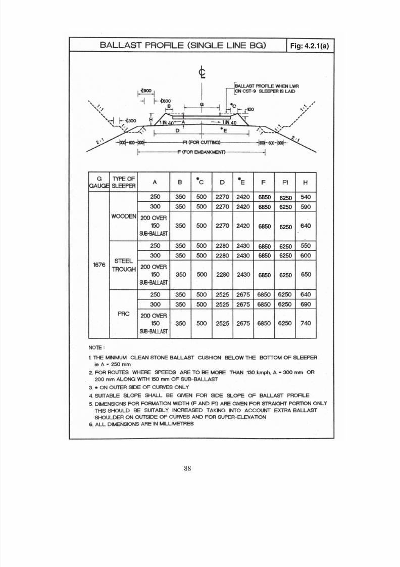
8/20/2019 lwrm
http://slidepdf.com/reader/full/lwrm 189/226
Fig: 4.2.1(a)Fig: 4.2.1(a)
40 40
6850 6250
6850 6250
6850 6250
6850 6250
6850 6250
6850 6250
88

8/20/2019 lwrm
http://slidepdf.com/reader/full/lwrm 190/226
1. 250 2. 100 300 200 150 3.
4.
5.
6.
52505850
52505850
5850
52505850
5850 5250
5850 5250
5850 5250
5250
5850 5250
5850 5250
89

8/20/2019 lwrm
http://slidepdf.com/reader/full/lwrm 191/226
Fig: 4.2.1(b)
40 40
52505850
52505850
52505850
52505850
52505850
52505850
52505850
5850 5250
5850 5250
5850 5250
5850 5250
5850 5250
500
500
89
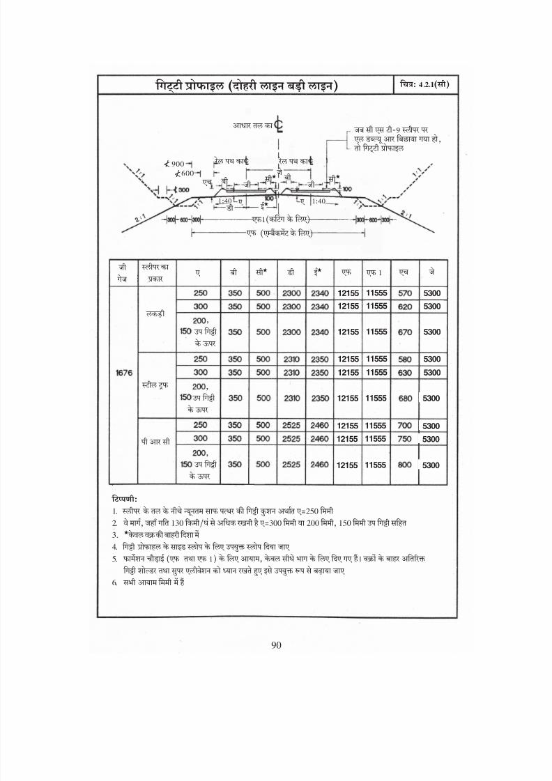
8/20/2019 lwrm
http://slidepdf.com/reader/full/lwrm 192/226
1. 250 2. 130 300 200 150 3.
4. 5.
6.
12155 11555
12155 11555
12155 11555
12155 11555
12155 11555
12155 11555
12155 11555
12155 11555
12155 11555
5300
5300
5300
5300
5300
5300
5300
5300
5300
</
</
90

8/20/2019 lwrm
http://slidepdf.com/reader/full/lwrm 193/226
40 40
Fig: 4.2.1(c)
12155 11555
12155 11555
12155 11555
12155 1155512155 11555
12155 11555
12155 11555
12155 11555
12155 11555
5300
5300
5300
53005300
5300
5300
5300
5300
90

8/20/2019 lwrm
http://slidepdf.com/reader/full/lwrm 194/226
1. 250 2. 100 300 200 150 3.
4. 5.
6.
92109810
92109810
92109810
92109810
92109810
92109810
92109810
92109810
92109810
</
</
91
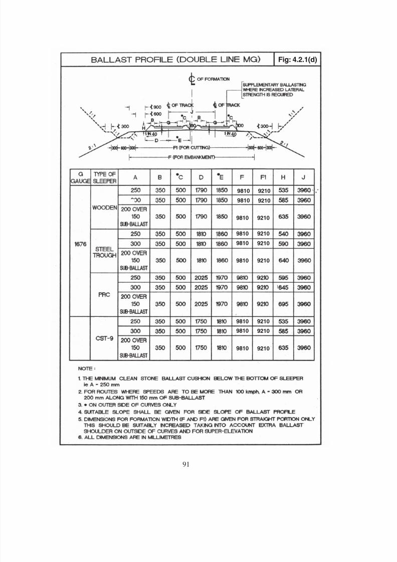
8/20/2019 lwrm
http://slidepdf.com/reader/full/lwrm 195/226
92109810
92109810
92109810
92109810
92109810
92109810
92109810
92109810
92109810
Fig: 4.2.1(d)
91
40 40

8/20/2019 lwrm
http://slidepdf.com/reader/full/lwrm 196/226
1
- 2 1 8 8
92

8/20/2019 lwrm
http://slidepdf.com/reader/full/lwrm 197/226
92
2 8 0
Fig: 4.4.3(a)
6 0
5 2
9 0
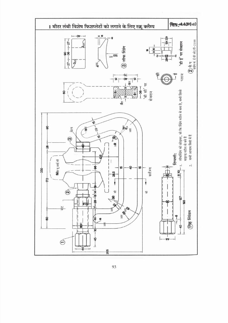
8/20/2019 lwrm
http://slidepdf.com/reader/full/lwrm 198/226
93

8/20/2019 lwrm
http://slidepdf.com/reader/full/lwrm 199/226
Fig: 4.4.3(b)
93

8/20/2019 lwrm
http://slidepdf.com/reader/full/lwrm 200/226
£
£
94

8/20/2019 lwrm
http://slidepdf.com/reader/full/lwrm 201/226
Fig: 4.4.3(c)
F I S H P L A T E S A
I N M I L L I M E
N S S H A L L B
I C T I O N
O F
94
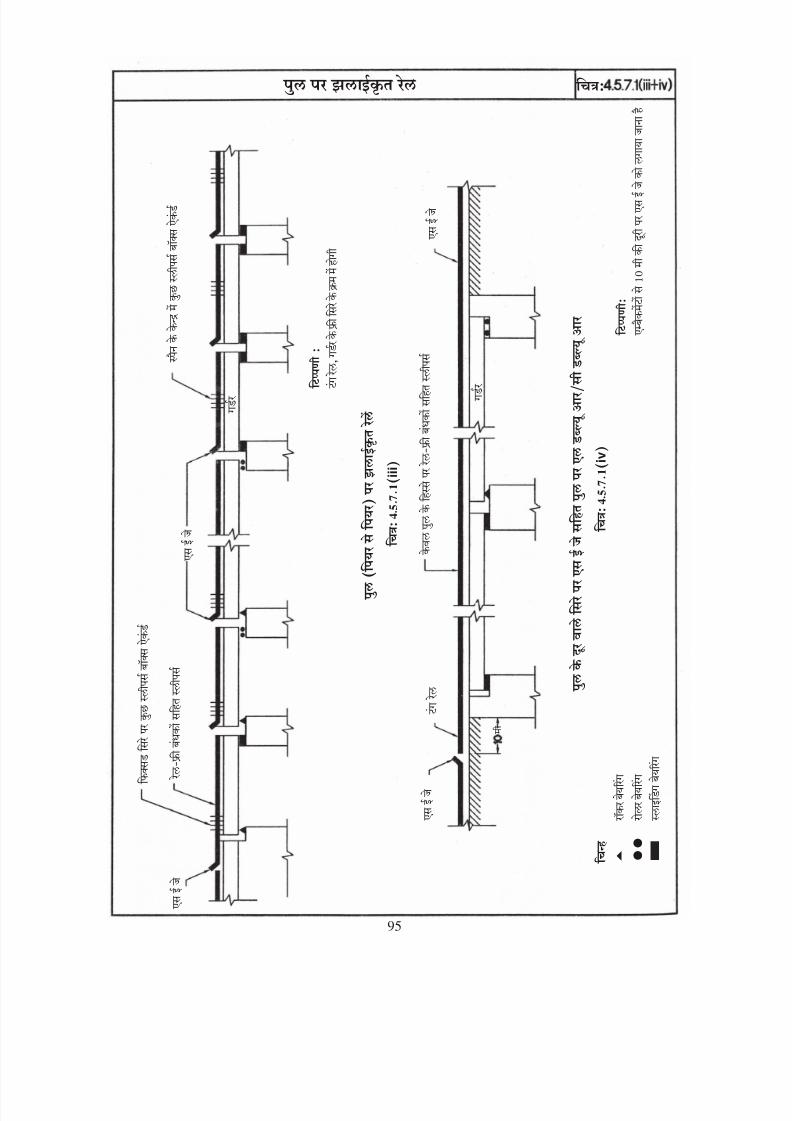
8/20/2019 lwrm
http://slidepdf.com/reader/full/lwrm 202/226
i i i
i v
95

8/20/2019 lwrm
http://slidepdf.com/reader/full/lwrm 203/226
Fig: 4.5.7.1(iii+iv)
L W R /
C W R
95
WELDED RAILS ON BRIDGE
W E L
D E D R A I L S O N B R I D G
E ( P I E R T O P I E R )
L W R / C W R O N
B R I D G E W I T
H S E J A T T H E F A R E N
D

8/20/2019 lwrm
http://slidepdf.com/reader/full/lwrm 204/226
D
- 2
O
O
O
96

8/20/2019 lwrm
http://slidepdf.com/reader/full/lwrm 205/226
Fig: 5.1.3
F O R
96
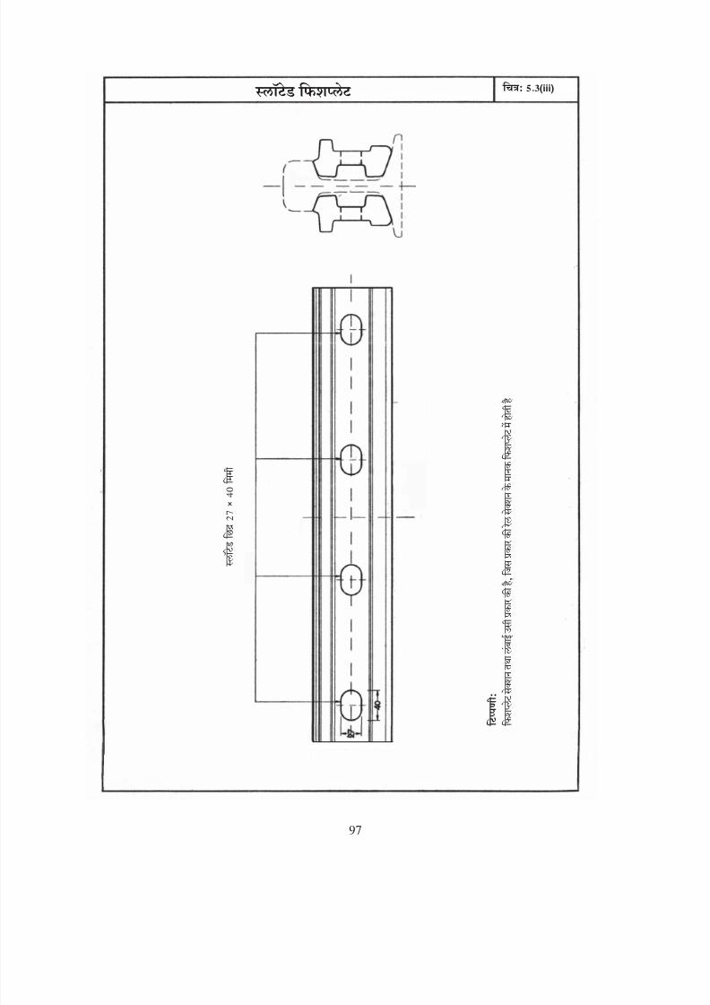
8/20/2019 lwrm
http://slidepdf.com/reader/full/lwrm 206/226
(iii)
97
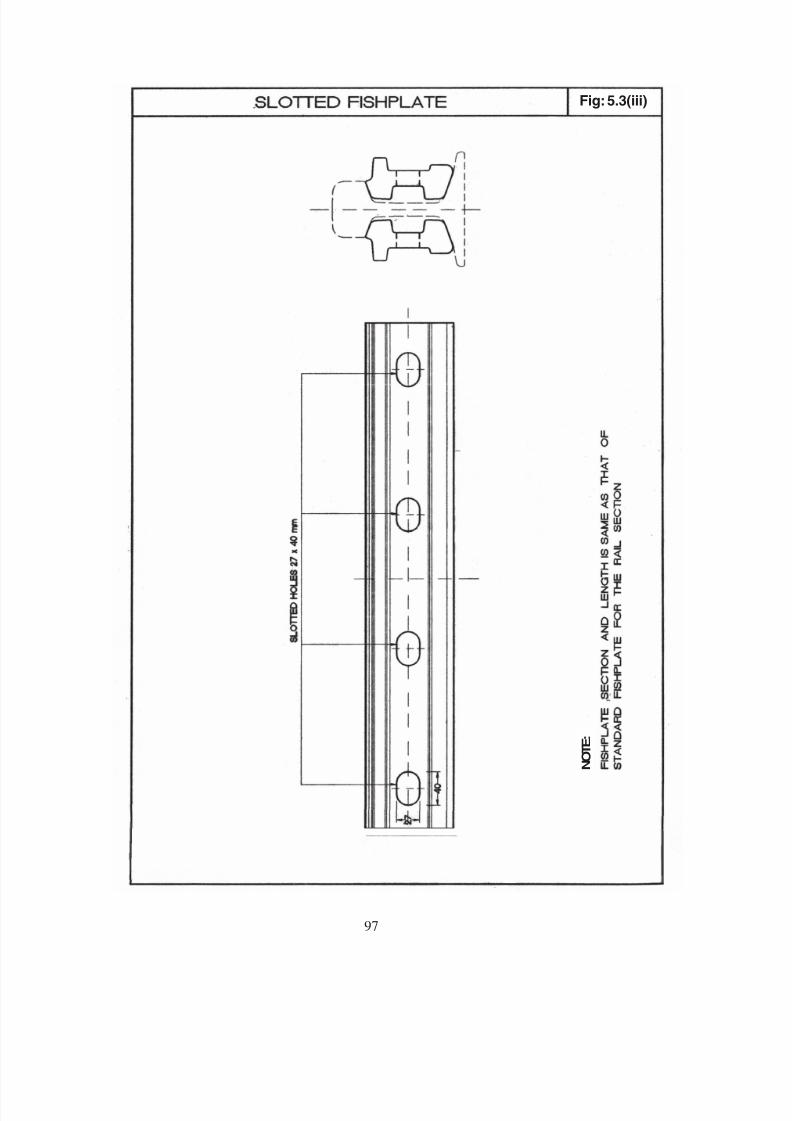
8/20/2019 lwrm
http://slidepdf.com/reader/full/lwrm 207/226
Fig: 5.3(iii)
N O T E :
97
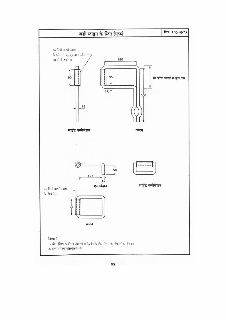
8/20/2019 lwrm
http://slidepdf.com/reader/full/lwrm 208/226
a
(viii)
98

8/20/2019 lwrm
http://slidepdf.com/reader/full/lwrm 209/226
Fig: 5.3(viii)(a)
:
.
.
BG
:
98
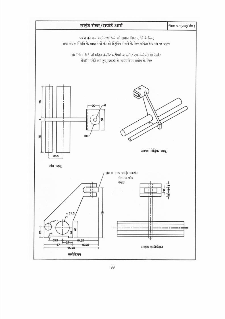
8/20/2019 lwrm
http://slidepdf.com/reader/full/lwrm 210/226
φ
(viii)
φ16
φ 81.5
99

8/20/2019 lwrm
http://slidepdf.com/reader/full/lwrm 211/226
Fig: 5.3(viii)(b1)SIDE ROLLER/SUPPORT ARM
φ16
φ 81.5
φ 30
99
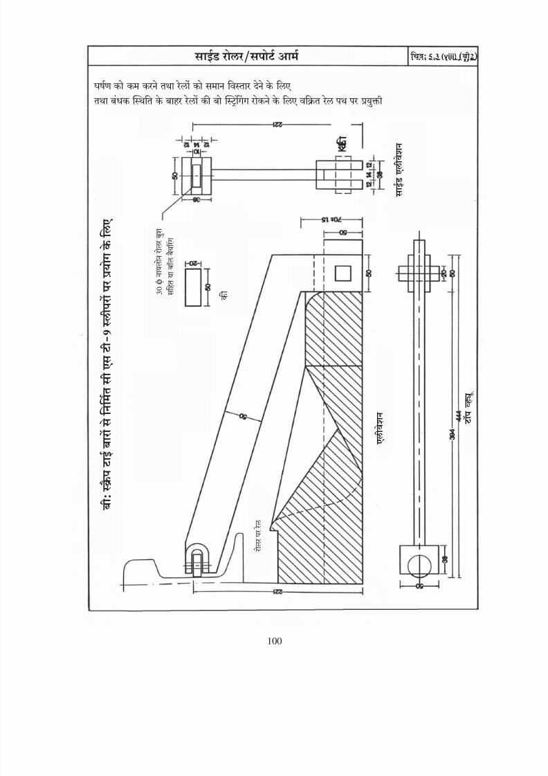
8/20/2019 lwrm
http://slidepdf.com/reader/full/lwrm 212/226
φ
b (viii)
100

8/20/2019 lwrm
http://slidepdf.com/reader/full/lwrm 213/226
SIDE ROLLER/SUPPORT ARM Fig: 5.3(viii) (b2)
φ
100

8/20/2019 lwrm
http://slidepdf.com/reader/full/lwrm 214/226
101
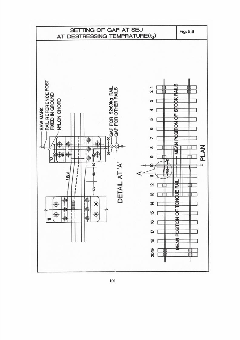
8/20/2019 lwrm
http://slidepdf.com/reader/full/lwrm 215/226
Fig: 5.6
4 0
6 0
R E F E R
E N C E
5 2 / 6
0 k g
101

8/20/2019 lwrm
http://slidepdf.com/reader/full/lwrm 216/226
o
>
o
o
o
o
o
102
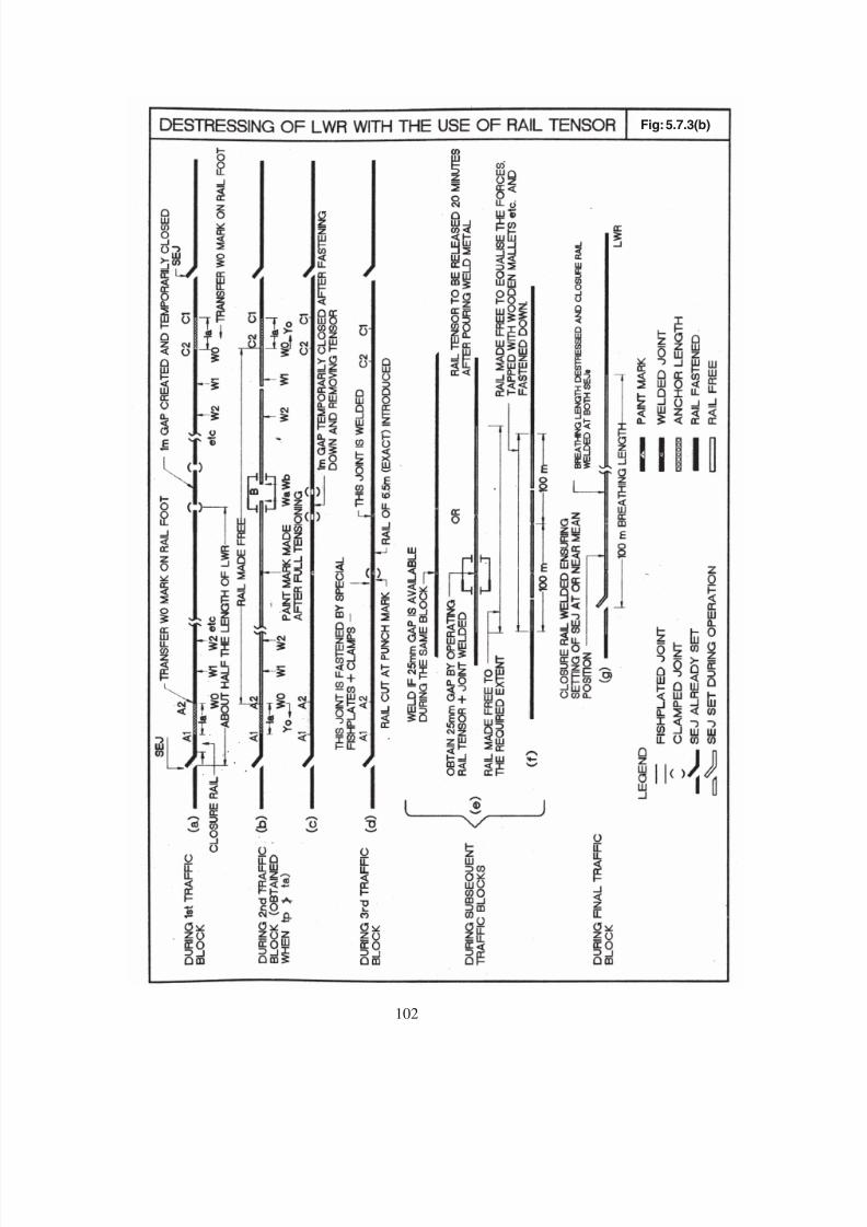
8/20/2019 lwrm
http://slidepdf.com/reader/full/lwrm 217/226
Fig: 5.7.3(b)
102
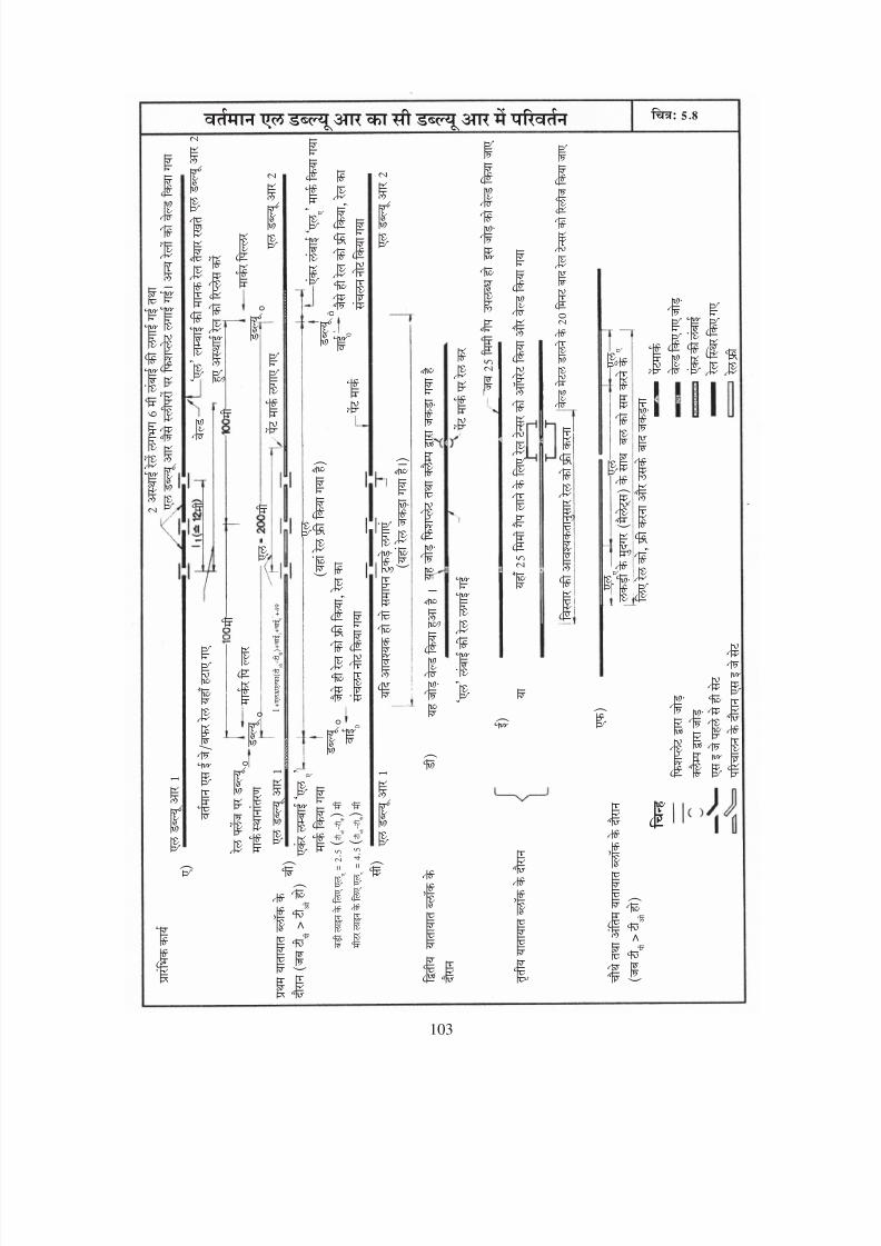
8/20/2019 lwrm
http://slidepdf.com/reader/full/lwrm 218/226
>
o
>
o
o
o
o
l x
103
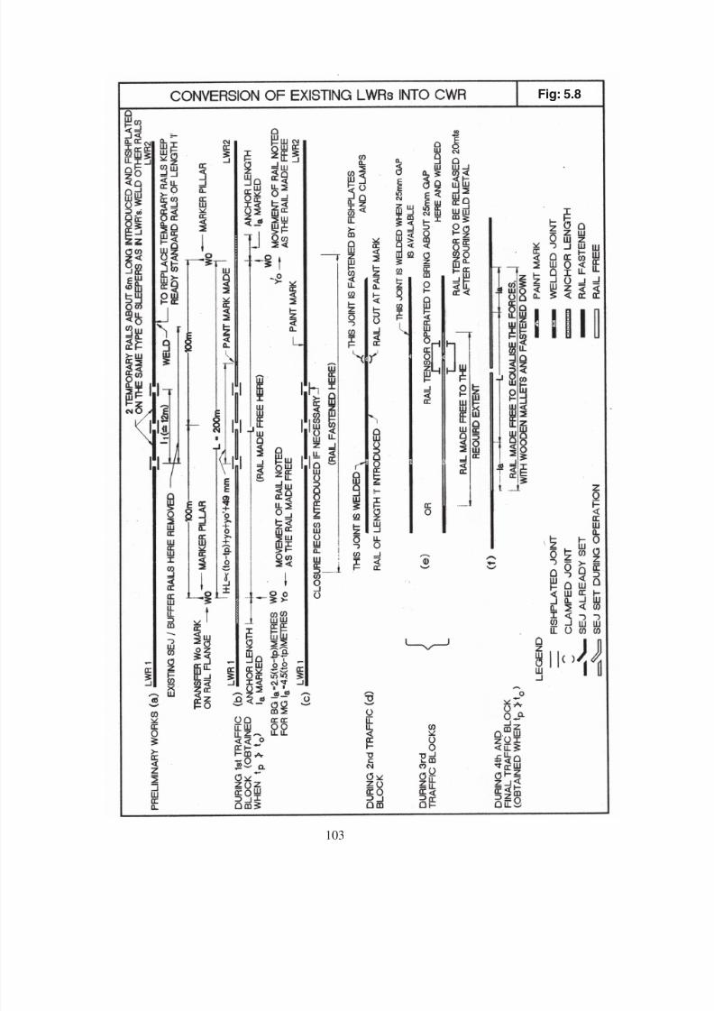
8/20/2019 lwrm
http://slidepdf.com/reader/full/lwrm 219/226
Fig: 5.8
103

8/20/2019 lwrm
http://slidepdf.com/reader/full/lwrm 220/226
I
II -
II -
104

8/20/2019 lwrm
http://slidepdf.com/reader/full/lwrm 221/226
Fig: 7.2.4, 7.2.5
PLATE
PLATE
tp
to.
1m
104
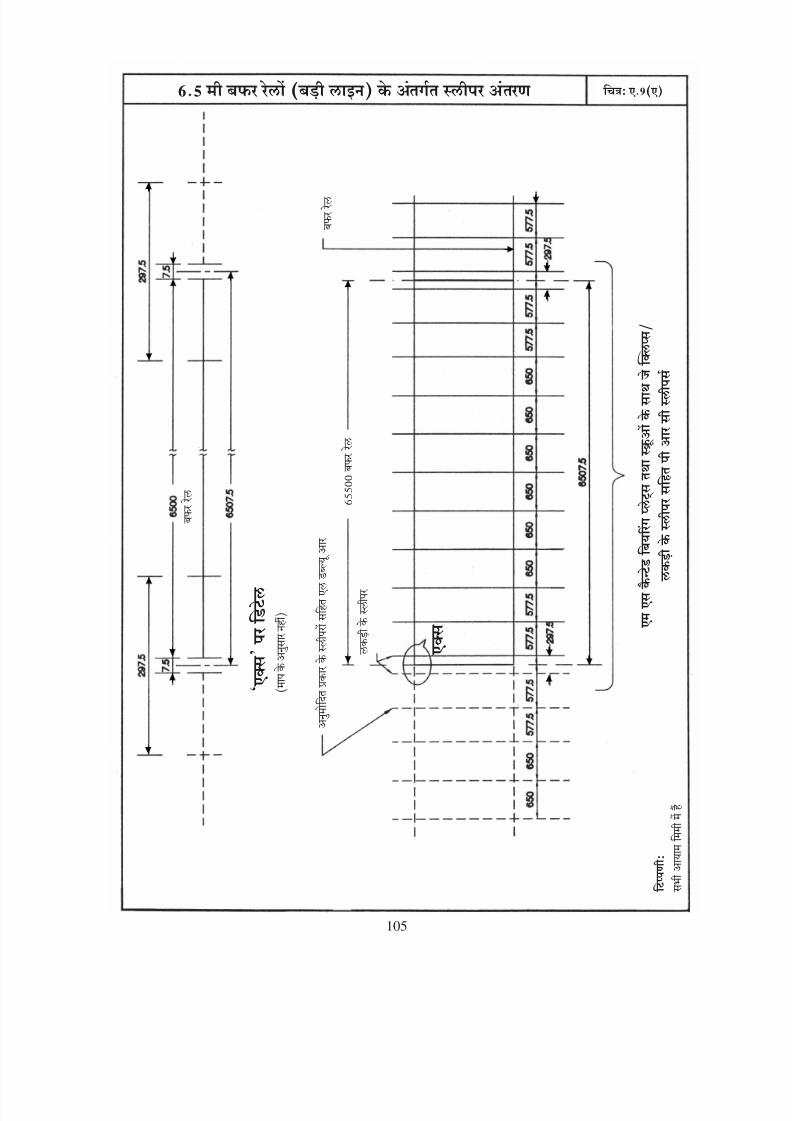
8/20/2019 lwrm
http://slidepdf.com/reader/full/lwrm 222/226
‘
’
105
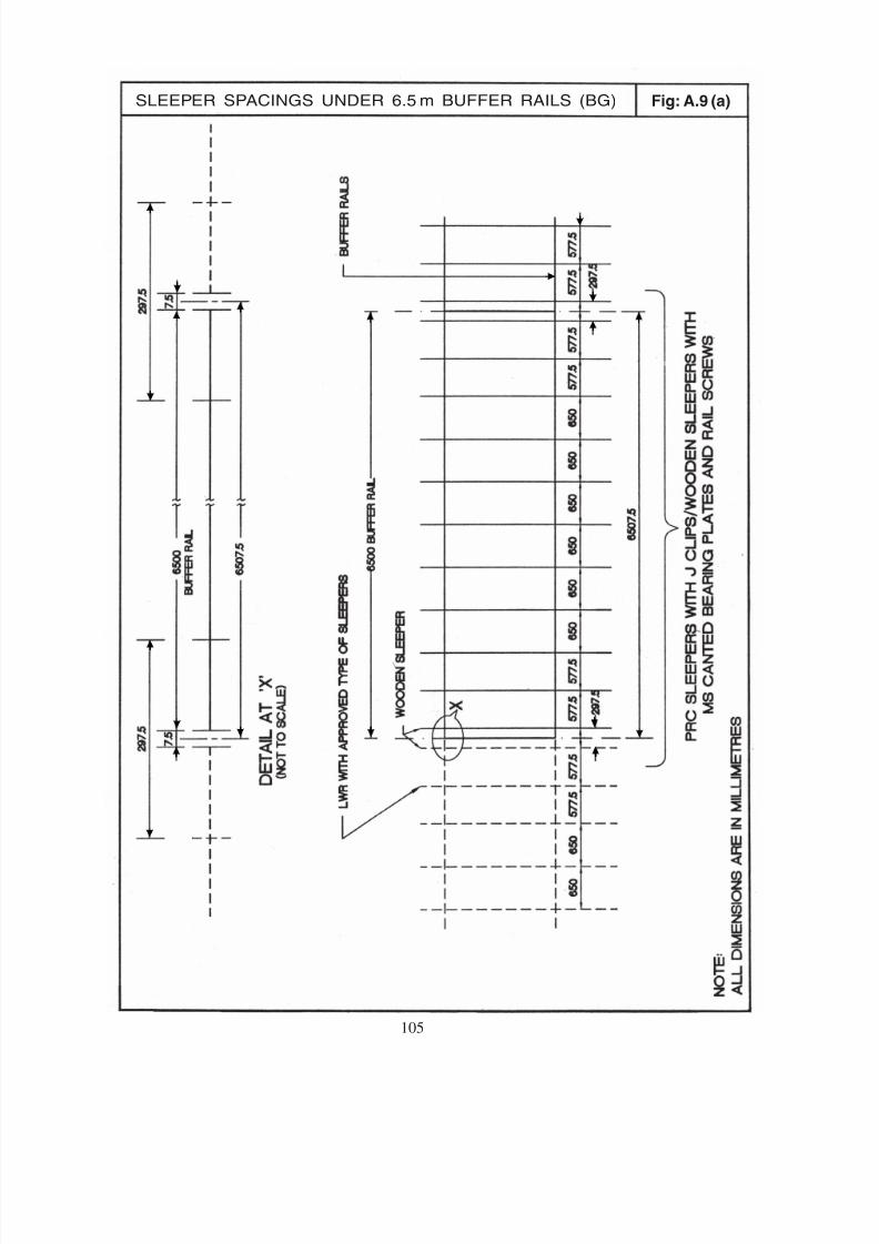
8/20/2019 lwrm
http://slidepdf.com/reader/full/lwrm 223/226
Fig: A.9 (a)SLEEPER SPACINGS UNDER 6.5 m BUFFER RAILS (BG)
105

8/20/2019 lwrm
http://slidepdf.com/reader/full/lwrm 224/226
~~
~~
~~
A
106
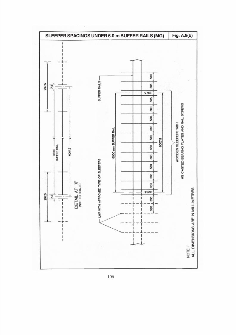
8/20/2019 lwrm
http://slidepdf.com/reader/full/lwrm 225/226
106
Fig: A.9(b)SLEEPER SPACINGS UNDER 6.0 m BUFFER RAILS (MG)
~~
~~
~~
8/20/2019 lwrm
http://slidepdf.com/reader/full/lwrm 226/226