lwcad basics - wtools3d.comwtools3d.com/pdf/manual.pdf · snap system ..... 3 constraint mode ......
TRANSCRIPT

LWCAD Basics...............................................................................................................3 Snap system.................................................................................................................3 Constraint mode ..........................................................................................................4 NURB Curves .............................................................................................................4 Realtime Curve Booleans ...........................................................................................4
Primitives........................................................................................................................5 Line.............................................................................................................................5 Curve ..........................................................................................................................6 Arc ..............................................................................................................................7 Arc angle.....................................................................................................................8 Circle tool....................................................................................................................9 Ellipse .........................................................................................................................9 Rectangle ..................................................................................................................10 Rec3p ........................................................................................................................10
Primitives II ..................................................................................................................11 Wall ..........................................................................................................................11 NGon ........................................................................................................................12 Star............................................................................................................................12 Pattern 1D .................................................................................................................13 Pattern 2D .................................................................................................................14 Pattern 2D rot ............................................................................................................15
Shape Library 2 .............................................................................................................16 add to 1d lib & add to 2d lib ......................................................................................16
Edit ...............................................................................................................................17 Del Segment ..............................................................................................................17 Trim ..........................................................................................................................17 Extend .......................................................................................................................17 Fillet..........................................................................................................................17 Blend.........................................................................................................................18 Offset ........................................................................................................................18
Mass Edit ......................................................................................................................19 Join Explode Curves................................................................................................19 Boolean 2D ...............................................................................................................19 Mass Round...............................................................................................................19 Mass Offset ...............................................................................................................20 Reduce Lines.............................................................................................................20 Connect Curves .........................................................................................................20 Merge Curves ............................................................................................................20
Convert .........................................................................................................................21 Extrude snap..............................................................................................................21 Curve To Poly ...........................................................................................................21 Poly To Curve ...........................................................................................................22 Curve To LWcur .......................................................................................................22
Analyze.........................................................................................................................22 Distance ....................................................................................................................22 Angle ........................................................................................................................22

Analyze Curves .........................................................................................................23 Snap Modify..................................................................................................................23 Move Snap ................................................................................................................23 Drag Snap..................................................................................................................24 Rotate snap................................................................................................................24 Scale snap..................................................................................................................24
Snap Multiply................................................................................................................25 Vector Clone .............................................................................................................25 Array Clone...............................................................................................................26 Rail Clone .................................................................................................................26 Mirror Clone .............................................................................................................27
Drill ..............................................................................................................................27 DArc .........................................................................................................................27 DCircle......................................................................................................................28 DEllipse ....................................................................................................................28 DRectangle................................................................................................................29 DRec3p .....................................................................................................................29 DPattern 1D...............................................................................................................30 DPattern 2D...............................................................................................................31 DPattern 2D rot .........................................................................................................32
Polygon Detail...............................................................................................................33 Engraver....................................................................................................................33 Profiler ......................................................................................................................34 Make Convex Make Quad.......................................................................................36 Cap Hole Tool 2 ........................................................................................................37
Options..........................................................................................................................39 LWCAD Options.......................................................................................................39 DXF ImportExport ...................................................................................................40

LWCAD Basics
Snap system
LWCAD since version 2 contains a complete snap engine which is fully integrated into all LWCAD tools. Snap modes are adjustable through the “Snap Panel”. Current version supports only polygons and NURB curves.
First section contains seven buttons for seven basic snap modes: NEAR – snap to nearest geometry END – snap to nearest ‘segment end’ of curve or ‘edge end’ of polygon PNT – snap to nearest point PERP – snap to nearest geometry which is perpendicular to previous handle of current tool TAN – snap to nearest geometry which is tangent to previous handle of current tool CENT – snap to center of nearest geometry INT – snap to intersection of curves. Currently works only with NURB curves in orthogonal view.
Second section contains ruler settings. RULER SNAP button enables ruler snap mode. Ruler mode works only with conjunction of snap to near or projective snap. It can works in absolute or relative mode.
Absolute mode allows you to set dimension of ruler step by the value control. Relative mode divides the ruler by defined division count.
Third section contains projective snap settings. PROJECTIVE SNAP button enables that mode. This mode creates perpendicular and tangent helper lines whose starts from projection point. Projection point is automatically assigned from last successful snap on geometry. Button freeze projection point makes that projection point fixed in case it is needed.
Fourth section is overloading of native grid snap. When GRID mode is custom, then you can set your desired grid value.
Fifth section contains angle snap settings. ANGLE SNAP button enables that mode. Angle snap value can be set as 90, 48, 30, 15, 5 and 1 degree.
Last clear all button disables all snap settings

Constraint mode
Every tool which is adjustable also by handles supports constrain mode. There are two types of constraint modes. Both operate with holding <ctrl> key, while dragging tool handle in viewport.
Picture on the left illustrates both cases.
First example picture is an ortho constraint mode which works on the last added handle of the Line Tool. This ortho mode behaves depended on previous handle position. Second example is the Rectangle tool which is constrained into square during constraint mode.
NURB Curves
LWCAD since version 2 is equipped with the industry standard NURB curves. LightWave native curves are no longer supported.
Realtime Curve Booleans
Each curve based primitive tool has possibility to turn on realtime curve Boolean mode. It works properly only with NURB curves which are placed in 2D orthogonal plane. Using curve Booleans on 3D object may result in corrupted object.
Following picture demonstrate how each mode affects rest of geometry in scene. Circle curve is affected by Rec3p tool:

Primitives
Primitives tab contains the tools for creating all basic geometric 2D primitives.
Line
Line is a multiple handle tool for creating lines and polylines. New point into line is added by each mouse click in viewport.
sketch color – defines sketch color of created line. Curve Boolean – defines realtime curve Boolean mode.
Closed Line ON/OFF check button which define whether line has connected first and last handle. Delete last removes last added handle.
mode – when handle mode is active then each handle is movable separately. When pivot mode is active then whole line is moved. point – current active handle index position actual handle position distance – adjustable distance for last edited end segment.
show distance ON/OFF check button for viewing line segments distance in the viewport. show angle ON/OFF check button for viewing angle between line segments in the viewport.

Curve
Curve is multiple handle tool for creating NURB curves. It is almost same as Line tool. New point into curve is also added by each mouse click in viewport. Current version is restricted to maximum eight control points.
sketch color – defines sketch color of created curve. Curve Boolean – defines realtime curve Boolean mode.
Closed Curve ON/OFF check button which define whether line has connected first and last handle. Delete last removes last added handle.
mode – when handle mode is active then each handle is movable separately. When pivot mode is active then whole line is moved. point – current active handle index position current handle position weight current handle weight distance – adjustable distance for last edited end segment. Distance is calculated only between handles not on the curve.
show distance ON/OFF check button for viewing line segments distance in the viewport. show angle ON/OFF check button for viewing angle between line segments in the

Arc
Arc is a four or six handles tool for creating precise arc sections. Tool works in two basic modes. 4point mode allows controlling start, end, center and middle point of arc section. tangent mode just adds four additional handles for adjusting arc endpoint’s tangents. This tool is restricted for 2D use only.
sketch color – defines sketch color of created arc. Curve Boolean – defines realtime curve Boolean mode.
mode – switch between two basic tool modes Start point arc start point handle End point arc end point handle
show radius ON/OFF check button for viewing arc radius in the viewport. show angle ON/OFF check button for viewing arc angle in the viewport.

Arc angle
Arc angle tool is a five handles tool for creating precise arc sections. This arc mutation allows setting of inner angle. This tool is restricted for 2D use only.
sketch color – defines sketch color of created arc. Curve Boolean – defines realtime curve Boolean mode.
Start point arc start point handle End point arc end point handle Middle point arc middle point handle
Center arc center handle Radius arc radius parameter Control point per turn defines intensity of the points to create arc curve.
show radius ON/OFF check button for viewing arc radius in the viewport. show angle ON/OFF check button for viewing arc angle in the viewport. parameters.

Circle tool
Circle tool is a three handle tool for creating precise NURB circles. Tool has the selectable pivot point, which can be changed with double mouse click. This tool is restricted for 2D use only.
sketch color – defines sketch color of created circle. Curve Boolean – defines realtime curve Boolean mode.
Center circle center handle Radius circle radius parameter
show radius ON/OFF check button for viewing radius in the viewport.
Ellipse
Ellipse tool is a five handle tool tool for creating precise NURB ellipses. Tool has the selectable pivot point, which can be changed with double mouse click. This tool is restricted for 2D use only
sketch color – defines sketch color of created ellipse. Curve Boolean – defines realtime curve Boolean mode.
Center ellipse center handle Width ellipse width parameter Height ellipse height parameter
show dimensions ON/OFF check button for viewing ellipse dimensions in the viewport.

Rectangle
Rectangle is an eight handle tool for creating rectangles. The tool has the four corner handles and the four side handles. This tool is restricted for 2D use only
sketch color – defines sketch color of created rectangle. Curve Boolean – defines realtime curve Boolean mode.
Center rectangle center Width rectangle width parameter Height rectangle height parameter
show dimensions ON/OFF check button for viewing rectangle dimensions in the viewport.
Rec3p
Rec3p tool is a three handle tool for creating arbitrary oriented rectangles. This tool is restricted for 2D use only.
sketch color – defines sketch color of created rectangle. Curve Boolean – defines realtime curve Boolean mode.
Start point rectangle start point handle End point rectangle end point handle Length rectangle height parameter
show dimensions ON/OFF check button for viewing rectangle dimensions in the viewport.

Primitives II
It is the additional set of the primitive tools with some specialized shapes. Series of three pattern tools are able to draw an unlimited count of the user defined arbitrary shapes.
Wall
Wall is a multiple handle tool for creating curve based 2D walls. It is derived from Line tool and behaves almost the same. This tool is restricted for 2D use only.
sketch color – defines sketch color of created line. Curve Boolean – defines realtime curve Boolean mode. side defines wall offset orientation offset – defines wall thickness
Closed Wall ON/OFF check button which define whether wall has connected first and last handle. Delete last removes last added handle.
mode – when handle mode is active then each handle is movable separately. When pivot mode is active then whole line is moved. point – current active handle index position actual handle position distance – adjustable distance for last edited end segment.
show distance ON/OFF check button for viewing line segments distance in the viewport. show angle ON/OFF check button for viewing angle between line segments in the viewport.

NGon
NGon is a two handle tool. It creates symmetric nsides curve based objects. Tool has the selectable pivot point, which can be changed with double mouse click. It is restricted for 2D use only.
sketch color – defines sketch color of created ngon. Curve Boolean – defines realtime curve Boolean mode.
mode – defines chosen tool mode. edge count – defines a count of object sides
Center circle center handle radius/edge – ngon radius or edge dimension depend on tool mode
show radius/edge ON/OFF check button for viewing radius or edge lenght in the viewport
Star
Star is a two handle tool. It creates symmetric nsides star objects. Tool has the selectable pivot point, which can be changed with double mouse click. Is is restricted for 2D use only.
sketch color – defines sketch color of created star. Curve Boolean – defines realtime curve Boolean mode.
tip count – defines count of star’s tips Center star center handle outer radius – inside star radius inner radius outside star radius
show radius ON/OFF check button for viewing radius in the viewport

Pattern 1D
Pattern 1D is a three handle tool for drawing with arbitrary oriented 1D curve shapes. It is derived from Rec3p tool and behaves very similar. Desired curve shape can be chosen from Shape Library which is available through the numeric panel. This tool is restricted for 2D use only.
sketch color – defines sketch color of created rectangle. Curve Boolean – defines realtime curve Boolean mode. count – defines multiplicity of the shape.
Shape Library thumbnail – this mini window shows available shapes in current library. shape – defines current selected preset in library library – defines current selected shape library
Start point start point handle position End point end point handle position Length shape height parameter
show dimensions ON/OFF check button for viewing tool dimension in the viewport. preview rows – defines the count of shape rows visible in preview window

Pattern 2D
Pattern 2D is a five handle tool for drawing with 2D curve shapes. Desired curve shape can be chosen from Shape Library which is available through the numeric panel. It has a selectable pivot point. User can change it with a double click. This tool is restricted for 2D use only.
sketch color – defines sketch color of created pattern. Curve Boolean – defines realtime curve Boolean mode.
Shape Library thumbnail – this mini window shows available shapes in current library. shape – defines current selected preset in library library – defines current selected shape library
flip horizontal – flips selected shapes leftright flip vertical – flips selected shapes up down set original dimension – sets tool handles position upon on the original shape dimension
Center rectangle center Width rectangle width parameter Height rectangle height parameter
show dimensions ON/OFF check button for viewing tool dimensions in the viewport. preview rows – defines the count of shape rows visible in preview window

Pattern 2D rot
Pattern 2D is a two handle tool for drawing with 2D curve shapes with arbitrary rotation. Desired curve shape can be chosen from Shape Library which is available through the numeric panel. One of two handles is always selected as pivot point. User can change it with a double click. This tool is restricted for 2D use only.
sketch color – defines sketch color of created pattern. Curve Boolean – defines realtime curve Boolean mode.
Shape Library thumbnail – this mini window shows available shapes in current library. shape – defines current selected preset in library library – defines current selected shape library
Flip side – flips pattern position around the handles pivot – defines pivot handle position base lenght – defines distance between the handles show dimension ON/OFF check button for viewing dimension in the viewport. preview rows – defines the count of shape rows visible in preview window

Shape Library 2 Shape Library is the collection of 1D and 2D NURB curves. It has default position on your drive in the “…\LightWave\Programs\Presets” folder. It is necessary to check that preset path in the LWCAD Options panel after installation! Because Shape Library since LWCAD 2 supports only NURB curves, therefore it is not backward compatible with the previous version 1.x !
Each shape file contains following important information: name library version library type (1D or 2D) original dimension NURB curve data
Shape files are platform independent text files. Therefore you can exchange your shapes between Macintosh and Windows platform.
add to 1d lib & add to 2d lib
Those two tools are able to add 1d or 2D shapes into the Shape Library. Both have the identical numeric panels therefore following description is valid also for 2D version.
add shape – adds curve from scene into shape library shape name – is user input for desired shape name
Shape Library thumbnail – this miniwindow shows available shapes in current library. shape – defines current selected preset in library delete shape – removes current selected preset in library library – defines current selected shape library create library – creates new empty library delete – remove current selected empty library
preview rows – defines the count of shape rows visible in preview window

Edit Edit section contains standard CAD toolset for editing NURB curves.
Del Segment
Del Segment tool removes segments from curves, lines and polylines by clicking on them. It is very fast way how to remove NURB segment from scene.
Trim
Trim operation removes clicked curve part which is intersected with the nearest boundary curves. This tool is restricted for 2D use only.
Extend
Extend operation prolongs clicked curve ends into nearest boundary curve. This tool is restricted for 2D use only.
Fillet
This tool is a standard CAD fillet operation between two NURB open curves. First and second phase is selecting the proper curve ends. Third is adjusting radius parameter. Both curve ends must have their projected tangents on the same orthogonal plane.
radius – defines arc radius between curves
show radius – ON/OFF check button for viewing dimension in the viewport.

Chamfer
This tool is a standard CAD chamfer operation between two NURB open curves. First and second phase is selecting the proper curve ends. Third is adjusting distance parameter. Both curve ends must have their projected tangents on the same orthogonal plane.
distance – defines distance from the point where chamfer begins to the imaginary intersection point of projected curves’ ends show distance – ON/OFF check button for viewing dimension in the viewport.
Blend
Blend tool creates a smooth connection between two curves’ ends. It works also in three phases. First and second phase is selecting the proper curve ends. Third phase is adjusting blending amount. Tool has no parameter for this just two handles which defines amount for each curve. This tools works also in 3D and It has no restrictions.
Offset
Offset tool is only for single curve use. This tool has two phases. First phase is selecting curve with mouse click. Second phase is adjusting offset parameter. It can be adjusted with handle in viewport or through the numeric panel
close ends – ON/OFF check button for connecting old and new offset curve. FLIP side – flips offset orientation offset – offset distance paramenter max. error – defines maximum premited error for offset operation
show distance – ON/OFF check button for viewing dimension in the viewport.

Mass Edit
Join Explode Curves
Those two commands can join and explode NURB curves. Join operation makes from many connected curves single curve. Explode operation divides each curve’s segment into separated curves.
Boolean 2D
Boolean 2d is an interactive tool which makes global intersections of curves and lines in the viewport. It automatically recognizes the plane of the actual geometry. Tool works with the two modes "Selfintersect" and "outline".
Mass Round
Curve Round is a multiple handle tool which creates fillet or chamfer operation on each corner point in the viewport. Every point on the curve which is surrounded by the line segments is considered as a corner point and the round tool makes a handle on this place. Handles can by controlled globally or individually by numeric panel or by moving mouse with LMB in the viewport.
round mode defines method for rounding corners.
handle mode – defines which handle is active, single or all of them handle actual handle index distance actual handle distance paramenter
show dimensions ON/OFF check button for viewing distance values in the viewport.

Mass Offset
This tool makes global offset for all curves, lines and polylines in the viewport. Offset value is adjustable by leftright moving mouse in the viewport with LMB or through the numeric panel.
MassOffset type – defines offset mode. remove curve removes old curves, only when “single side” mode is active MassOffset – offset value max. error – defines maximum premited error for offset operation
show dimensions ON/OFF check button for viewing offset distance in the viewport.
Reduce Lines
Reduce Lines eliminate redundant points on polylines which are surrounded by parallel segments.
Connect Curves This command makes the line connections between every nearest opened ends of curve. Intersections are not taken into account.
Merge Curves
Merge Curve removes identical redundant curves from scene. If the two or more curves has the same point positions, this command keeps only one and delete rest of them.

Convert
Extrude snap
Extrude snap tool is overloading of the original Extrude tool in LightWave. This new tool supports snap modes and NURB curves. Extruded polygons are automatically aligned.
max freeze error – defines curve detail which affects polygon density of the extruded poly offset – defines extrude offset
show dimension ON/OFF check button for viewing extrude offset distance in the viewport.
Curve To Poly
Curve to Poly tool converts curves into polygons. It is primarily designed for conversion of complicated curve based floor plans into polygonal form. Highly recommended is using Boolean 2D operation with selfintersect option before. Next recommended is also using complementary ‘Analyze Curves’ tool. It is useful for finding hidden disconnections between curves whose might result in wrong conversion result. This tool is restricted for 2D use only.
max freeze error defines curve detail for conversion Convex Polygons – defines whether converted polygons must be only convex Remove Curves – removes original curves after conversion Flip Polygons – this parameter defines polygons orientation after conversion Sketch Color Surface – if active then polygon surfaces are created from sketch color information of the original curves.

Poly To Curve
Poly to Curve operation converts every polygon edge into line curve. Redundant curves are deleted then.
Curve To LWcur
Curve To LWcur is backward support for existing curve based tools in LightWave. This operation converts Nurb curves into old curves.
Analyze
Distance
Distance tool is a two handle tool for measuring dimensions in the scene.
distance absolute distance value between handles
X x axis distance between handles Y y axis distance between handles Z z axis distance between handles
show distance ON/OFF check button for viewing in the viewport. show XYZ ON/OFF check button for viewing X,Y,Z distance in the viewport.
Angle
Angle tool is a three handle tool for measuring angles in the scene. It works in 2D orthogonal viewport and since LWCAD 2 also in 3D.
angle measured angle parameter

Analyze Curves
Analyze Curves tool is very useful for discovering hidden flaws in the curve based object. It shows all opened curves ends which are not connected to other curves. If this disconnection is very snall it can be invisible by user. Those invisible disconnections then can cause a wrong result after conversion to polygons.
open curve ends all open curve ends in the viewport are marked with green helpers
loop disconetions all unconected open curve ends in the viewport are marked with green helpers
Snap Modify
Move Snap
Move Snap is a two handle toll which precisely translates selected geometry. It works in all viewports.
offset – defines move vector show dimensions ON/OFF check button for viewing move distance in the viewport. show dimensions ON/OFF check button for viewing XYZ distance in the viewport.

Drag Snap
Drag Snap is a multiple handle tool which precisely translates points in the objects. It is the very effective tool for connecting objects.
handle position drags vector for actual handle actual handle –current handle index
show dimensions ON/OFF check button for viewing handle distance in the viewport. show dimensions ON/OFF check button for viewing handle XYZ distance in the viewport.
Rotate snap
Rotate Snap is a three handle tool which precisely rotates selected geometry. It works in 2D as well as in 3D viewports. Rotation plane in 3D viewport is calculated from handles position.
Angle – defines rotation parameter
show angle ON/OFF check button for viewing angle parameter in the viewport.
Scale snap
Scale Snap tool precisely scales or stretches selected geometry. It works in 2D and 3D viewports.

mode tool has a three modes: 1D stretch object along the line 2D scale object in the plane 3D scale object in 3d space Factor scale or stretch ratio distance – defines desired distance after scale operation
show factor ON/OFF check button for viewing scale parameter in the viewport. show distance ON/OFF check button for viewing scale distance in the viewport.
Snap Multiply
Vector Clone
Vector Clone is an interactive tool for multiplying geometry along defined vector. It supports all geometry elements used in LightWave.
count – defines number of desired clones offset defines clone vector
show distance ON/OFF check button for viewing clone vector distance in the viewport. show XYZ ON/OFF check button for viewing XYZ distance in the viewport.

Array Clone
Array Clone is an interactive tool which creates clones along X,Y and Z axis It supports all geometry elements used in LightWave.
X count – defines number of desired clones along X axis Y count – defines number of desired clones along Y axis Z count – defines number of desired clones along Z axis offset defines clone distance for each axis
show distance ON/OFF check button for viewing distances in the viewport.
Rail Clone
Rail Clone is an interactive tool for cloning objects along the curve. It supports all geometry elements used in LightWave. But rail curve must be NURB curve. LW curves are not supported. It can be placed in background or primary layer. In case it is in primary layer it must be unselected.
count defines number of clones along the curve oriented – defines whether the clones have aligned orientation along the curve or not.

Mirror Clone
Mirror Clone is an interactive tool which creates precise mirrored clones. It supports all geometry elements used in LightWave.
It works with two handles in the 2D viewport and with three handles in the perspective viewport. Two handles defines mirror line and three handles defines mirror plane.
Drill
DArc
Arc is a four or six handles tool for slicing, cutting or drilling polygons with arc section. Tool works in two basic modes. 4point mode allows controlling start, end, center and middle point of arc section. tangent mode just adds four additional handles for adjusting arc endpoint’s tangents.
surface – defines the surface for new created polygons after drill operation mode – defines current realtime drill mode max freeze error – defines detail of curve for conversion
mode – switch between two basic tool modes Start point arc start point handle End point arc end point handle
show radius ON/OFF check button for viewing arc radius in the viewport. show angle ON/OFF check button for viewing arc angle in the viewport.

DCircle
Circle tool is a three handle tool for slicing, cutting or drilling polygons with circle. Tool has the selectable pivot point, which can be changed with double mouse click. This tool is restricted for 2D use only.
surface – defines the surface for new created polygons after drill operation mode – defines current realtime drill mode max freeze error – defines detail of curve for conversion
Center circle center handle Radius circle radius parameter
show radius ON/OFF check button for viewing radius in the viewport.
DEllipse
Ellipse tool is a five handle tool for slicing, cutting or drilling polygons with ellipse. Tool has the selectable pivot point, which can be changed with double mouse click. This tool is restricted for 2D use only
surface – defines the surface for new created polygons after drill operation mode – defines current realtime drill mode max freeze error – defines detail of curve for conversion
Center ellipse center handle Width ellipse width parameter Height ellipse height parameter
show dimensions ON/OFF check button for viewing ellipse dimensions in the viewport.

DRectangle
Rectangle is an eight handle tool for slicing, cutting or drilling polygons with rectangle. The tool has the four corner handles and the four side handles. This tool is restricted for 2D use only
surface – defines the surface for new created polygons after drill operation mode – defines current realtime drill mode
Center rectangle center Width rectangle width parameter Height rectangle height parameter
show dimensions ON/OFF check button for viewing rectangle dimensions in the viewport.
DRec3p
Rec3p tool is a three handle tool for slicing, cutting or drilling polygons with arbitrary oriented rectangle. This tool is restricted for 2D use only.
surface – defines the surface for new created polygons after drill operation mode – defines current realtime drill mode
Start point rectangle start point handle End point rectangle end point handle Length rectangle height parameter
show dimensions ON/OFF check button for viewing rectangle dimensions in the viewport.

DPattern 1D
Pattern 1D is a three handle tool for slicing, cutting or drilling polygons with arbitrary oriented 1D curve shape. It is derived from Rec3p tool and behaves very similar. Desired curve shape can be chosen from Shape Library which is available through the numeric panel. This tool is restricted for 2D use only.
surface – defines the surface for new created polygons after drill operation mode – defines current realtime drill mode max freeze error – defines detail of curve for conversion count – defines multiplicity of the shape.
Shape Library thumbnail – this mini window shows available shapes in current library. shape – defines current selected preset in library library – defines current selected shape library
Start point start point handle position End point end point handle position Length shape height parameter
show dimensions ON/OFF check button for viewing tool dimension in the viewport. preview rows – defines the count of shape rows visible in preview window

DPattern 2D
Pattern 2D is a five handle for slicing, cutting or drilling polygons with 2D curve shape. Desired curve shape can be chosen from Shape Library which is available through the numeric panel. It has a selectable pivot point. User can change it with a double click. This tool is restricted for 2D use only.
surface – defines the surface for new created polygons after drill operation mode – defines current realtime drill mode max freeze error – defines detail of curve for conversion
Shape Library thumbnail – this mini window shows available shapes in current library. shape – defines current selected preset in library library – defines current selected shape library
flip horizontal – flips selected shapes leftright flip vertical – flips selected shapes up down set original dimension – sets tool handles position upon on the original shape dimension
Center rectangle center Width rectangle width parameter Height rectangle height parameter
show dimensions ON/OFF check button for viewing tool dimensions in the viewport. preview rows – defines the count of shape rows visible in preview window

DPattern 2D rot
Pattern 2D is a two handle tool for slicing, cutting or drilling polygons with 2D curve shape with arbitrary rotation. Desired curve shape can be chosen from Shape Library which is available through the numeric panel. One of two handles is always selected as pivot point. User can change it with a double click. This tool is restricted for 2D use only.
surface – defines the surface for new created polygons after drill operation mode – defines current realtime drill mode max freeze error – defines detail of curve before conversion to polygons
Shape Library thumbnail – this mini window shows available shapes in current library. shape – defines current selected preset in library library – defines current selected shape library
Flip side – flips pattern position around the handles pivot – defines pivot handle position base lenght – defines distance between the handles show dimension ON/OFF check button for viewing dimension in the viewport. preview rows – defines the count of shape rows visible in preview window

Polygon Detail
Engraver
Engraver is an excellent tool for creating details on objects. It very easily creates a cornice or wall molding. Tool can be used only on four point polygons. If more four polygons are connected into uniform array then this considered as one area and engraver use it as a single entity. It can operate on multiple areas in one shot. Tool uses Shape Library 1D.
close ends ON/OFF check button for closing the holes which are created when the tool rip the mesh. base polygons aligns or removes area polygons. max freeze error – defines detail of curve before conversion to polygons count – number of shapes used per area
Shape Library thumbnail – this mini window shows available shapes in current library. shape – defines current selected preset in library library – defines current selected shape library
mode defines which area is adjusted, single or at once offset parameter of the shape height on area rotate base 90 flips shape orientation set original ratio sets original shape ratio adjusted to current dimension
show helpers ON/OFF check button for viewing area helpers in the viewport. show dimensions ON/OFF check button for viewing offsets for each area in the viewport. preview rows – defines the count of shape rows visible in preview window

Profiler
The Profiler is universal tool for extruding arbitrary profiles along the curve. It can operate with one or more curves in one shot. Extruded shape is used from Shape Library 2D.
close ends ON/OFF check button which define whether profile's ends are closed or not. shape pivot – defines shape position on rail curve. Center option places shape as centered on curve and 1,2,3,4 options into corner points. rail curve max freeze error defines rail curve detail shape curve max freeze error defines shape curve detail
Shape Library thumbnail – this mini window shows available shapes in current library. shape – defines current selected preset in library library – defines current selected shape library
mode defines which radius is adjusted, single or all at once width defines radius value angle defines rotation of shape around the rail curve rotate 90 profile adds 90 degrees to angle value flip horizontal – flips selected shapes leftright flip vertical – flips selected shapes up down set original dimension – sets width upon on the original shape dimension
show helpers radius handle is visualized with green rectangle. show dimensions ON/OFF check button for viewing radius value in the viewport. preview rows – defines the count of shape rows visible in preview window

Fix Polygons
Fix Polygons 2
Fix polygons is an adjustable multicommand for correction polygon errors and simplifying complicated polygons. Every step takes one undo, except for remove 0,1,2 point polygons where all three take one undo. Therefore, in the worst case, this multicommand can take maximum five undo steps. Tool is working only in the primary layer.
The panel has seven parameters:
Remove 0,1,2 point polygons Every polygon with 0,1,2 points is removed from layer.
Delete redundant points This step merges points in every polygon. Points are merged only within each polygon separately. Fix pol scratches This step removes all scratches in polygon.
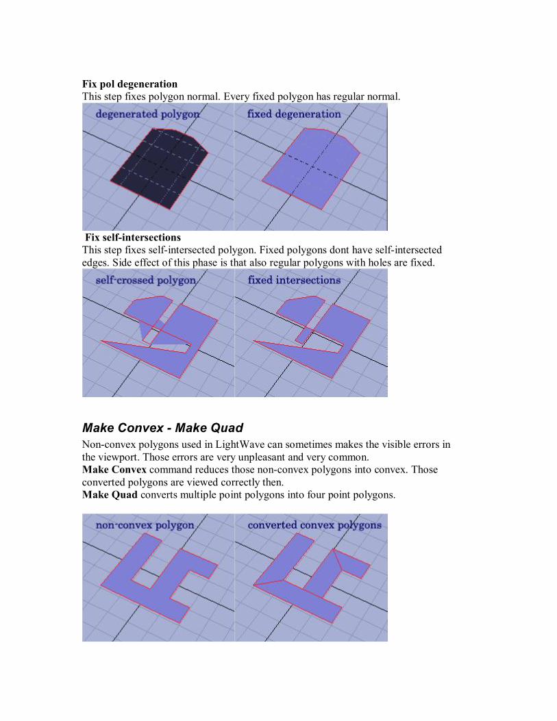
Fix pol degeneration This step fixes polygon normal. Every fixed polygon has regular normal.
Fix selfintersections This step fixes selfintersected polygon. Fixed polygons dont have selfintersected edges. Side effect of this phase is that also regular polygons with holes are fixed.
Make Convex Make Quad Nonconvex polygons used in LightWave can sometimes makes the visible errors in the viewport. Those errors are very unpleasant and very common. Make Convex command reduces those nonconvex polygons into convex. Those converted polygons are viewed correctly then. Make Quad converts multiple point polygons into four point polygons.

Cap Hole Tool 2
Cap Hole is an interactive tool to solve all types of holes. It works in three phases. First phase localizes hole. Then localized hole is merged. If hole is not solved with the merge phase, then third phase closes hole with the patch. All three phases runs in the real time and every change has an immediately effect in the viewport. Tool works only in the primary layer.
Show open edges Open edges on the polygons are marked with the green lines. If the parameter is "NO HOLE" then open edges are marked only if object doesn't have a regular hole. Open edges count Open edge's count in actual layer.
Merge hole ON/OFF parameter enable/disable merge hole phase. Relative/Absolute distance Merge hole base parameter. Higher values could solve also small cracks in objects.
Cap hole ON/OFF parameter for cap hole phase. Preferred angle Cap hole algorithm has two basic modes. Difference between them is illustrated on the following picture.

Maximum angle Maximum angle parameter is the maximum acceptable angle between normal of adjacent cap's polygons and original polygons situated on the boundary of the hole. Polygons type Polygons used for covering hole could be planar or triangles. Planar holes are always covered by planar polygons and this parameter is ignored.
Max nonplanarity Maximum allowed polygon's nonplanarity. Auto surface ON/OFF parameter for automatic surface. Cap time limit Maximum time for cap hole algorithm.

Options
LWCAD Options
LWCAD Options panel contains basic global option parameters.
about – panel with version and build number. online help –web version of the current manual
serial number – serial number for the current installed license key number – unlock code obtained from wtools3d.com server hardware number – number generated from attached dongle
activate LWCAD – read install notes how to use this option!
preset path preset path location for Shape Library tools. It has default position on your drive in the “…\LightWave\Programs\Presets” folder. dimension unit – switch between dimension units type snap comments – defines how much information is shown in viewport after snap event snap threshold – user defined snap distance in viewport
default settings sets factory settings

DXF ImportExport
This duo of commands serves as a gate between LightWave and professional CAD programs. Imported geometry is stored in current selected layer and layer information from DXF file is transformed into sketch color information. When exporting, all geometry in selected layer is exported and each sketch color is exported as different layer.
DXF Import: Supported entities:
3DFACE triangle or square polygon ARC circle arc CIRCLE circle ELLIPSE ellipse or elliptic arc LINE simple line POLYLINE polyline or polyface mesh LWPOLYLINE polyline or polyface mesh SPLINE spline curve with maximal degree 6
In imported dxf file can be blocks. Blocks will be replaced by geometry witch they are assembled. Every unsupported entity or parameter is ignored
DXF Export: Exported entities:
3DFACE triangle or square (more than four point polygon is triangulated). Indexation of complex meshes will be not preserved.
SPLINE every curve will be stored as spline with appropriate parameters