lvd unit heater, temper - xamk unit heater catalogue operation the speed switch is designed for use...
TRANSCRIPT

LVD Unit Heater, TEMPER®
Fläkt Woods is providing solutions for ventilation and air climate for buildings as well as fan solutions for Industry and Infrastructure.

Fläkt Woods 10016 GB 04.02 2 Information contained herein is subject to alteration without notice.
LVD Unit Heater CATALOGUE
Contents
Product Description . . . . . . . . . . . . . . . . . . . . . . . . . . . . . . . . .3
Product Overview . . . . . . . . . . . . . . . . . . . . . . . . . . . . . . . . .4-5
Installation Packages . . . . . . . . . . . . . . . . . . . . . . . . . . . . . .6-9
Installation Examples . . . . . . . . . . . . . . . . . . . . . . . . . . .10-14
Accessories
Unit Heaters . . . . . . . . . . . . . . . . . . . . . . . . . . . . . . . . . . .15
Control Equipment . . . . . . . . . . . . . . . . . . . . . . . . .16-23
Sizing . . . . . . . . . . . . . . . . . . . . . . . . . . . . . . . . . . . . . . . . . . . . . .24
Installation particulars . . . . . . . . . . . . . . . . . . . . . . . . . . . . .25
Capacity Chart . . . . . . . . . . . . . . . . . . . . . . . . . . . . . . . . . . . . .26
Capacity Tables, water, LVDV . . . . . . . . . . . . . . . . . . .27-29
Technical Particulars . . . . . . . . . . . . . . . . . . . . . . . . . . . .30-32
Dimensions and Weights . . . . . . . . . . . . . . . . . . . . . . . . . . .33
Wiring Diagrams . . . . . . . . . . . . . . . . . . . . . . . . . . . . . . . .34-39
Product Codes . . . . . . . . . . . . . . . . . . . . . . . . . . . . . . . . . .40-42
Packaging – Installation Packages . . . . . . . . . . . . . . . . . .43

Fläkt Woods 10016 GB 04.02 3 Information contained herein is subject to alteration without notice.
LVD Unit Heater CATALOGUE
Product DescriptionThe type LVDV fan-assisted unitheaters are designed for spaceheating in shop entrances, lobbies,doorways, warehouses and work-shops, garages and similar premis-es. The unit is designed for mount-ing beneath a ceiling. Hot water isused as the heating medium.All units comply with EU require-ments on machinery safety,91/368/EEC.The fan-assisted unit heater:– is made of galvanised sheet steel,
painted white– has low overall height, short or
long throw – can thus be fitted inpremises with various ceiling heights
– can be fitted with an air dischar-ge device to increase the throw
– is easy to clean; simple to service– can easily be mounted against
the ceiling or suspended from it.
The LVDV incorporates a quiet fanimpeller and flange motor to IECPubl. 34-1, available in two versions:– Single-phase, 230 V, with thermo-
static contacts in the motor -winding, reconnectible for three speeds, factory-wired for running at high speed
– 3-phase, 400 V, 4-pole or 6-pole motor.
Both motors have degree of protec-tion IP54.
Materials and FinishUnit casing: Made of galvanisedsheet steel, painted white (RAL9010). On delivery, the white-painted surfaces are covered withprotective transparent plastic foil.Heating coil: Finned coil consist-ing of aluminium fins and coppertubes. Brass connections.Impeller: Axial-flow impellermade of aluminium and sheetsteel.
PackagingThe unit heater and its accessoriesare delivered in corrugated card-board cartons.CE labelled.
LVDV Unit Heater
(Equipped with the LVDZ-33, ATC)
Fläkt Woods 10016 GB 04.02 4 Information contained herein is subject to alteration without notice.
LVD Unit Heater CATALOGUE
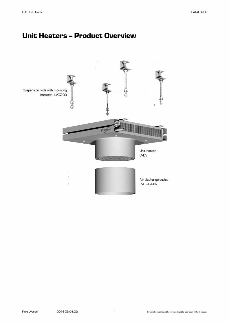
Unit Heaters – Product Overview
Suspension rods with mountingbrackets, LVDZ-03
Unit heater,LVDV
Air discharge device,LVDZ-04-bb

LVD Unit Heater CATALOGUE
Fläkt Woods 10016 GB 04.02 5 Information contained herein is subject to alteration without notice.
Automatic fan control,simple, FHCLVDZ-15-4 1 x 230 V, 2A
Valve with thermal actua-tor, LVDZ-17-3
Room thermostat for fanoperation, IP 54,
LVDZ-19-3
Temperature sensor,RG Humidity, LVDZ-35-1
LVDZ-35-2
Remote control for ATC,LVDZ-21-3LVDZ-21-4
Timer for ATC,LVDZ-22-3
Speed selector switch,LVDZ-14
Speed selector switch, 2A,LVDZ-24-3
Speed selector switch, 9 ALVDZ-28
Transformer, 2A,LVDZ-25-3
Junction box,LVDZ-30
Accessories and Control Equipment
Room thermostat forFan operation, IP 30,
LVDZ-18-3
Automatic unit heater control,advanced, ATCLVDZ-29 1 x 230 V, 9A
Auxiliary module,network connection,
LVDZ-37
Remote control unit,infrared,LVDZ-36
Valve with actuator, quick-action,
LVDZ-17-4
Automatic unit heater control,advanced, ATCLVDZ-33 1 x 230 V, 2A
Automatic fan control,simple, FHCLVDZ-34 3 x 400 V

To make the task of selecting control equipment easier,we have produced ready-to use package solutions forthe most common control options. You can of coursecombine whichever installation package you choosewith other accessories. See the Installation ExamplesSection in this catalogue.The components that make up the various installationpackages are also sold as separate accessories.
ApplicationsA-Box – entrances, gateways, warehouses, garages.B-Box – entrances, workshops, shopping centres, sport centresC-Box – same as B-Box but where higher demands, such as night-time temperature reduction, alarms,
network connection or microprocessor substation (0-10V) control, must be satisfied.
Installation Packages
Fläkt Woods 10016 GB 04.02 6 Information contained herein is subject to alteration without notice.
LVD Unit Heater CATALOGUE
Unit – control accessories A-Box B-Box C-Box
Unit heater x x x
Junction box x x -
Room thermostat x - -
Automatic fan control, - x -FHC, simple
Automatic unit heater control, - - xATC, advanced
Temperature sensor - x x
Liquid valve x x x
Documentation x x x
x = included
Survey - Components of the boxes
A-Box Temperature-controlled airflow control, on/off, with liquidvalve, on/off.
B-Box Temperature-controlled airflow control in 3 steps or swit-ched-off position with liquid valve, on/off.
C-Box Temperature-controlled airflow control in 3 steps or swit-ched-off position with liquid valve, on/off. With provision fortimer control. 0-10 V control, remote control, network connection, alarm output.
Survey - Functions

Fläkt Woods 10016 GB 04.02 7 Information contained herein is subject to alteration without notice.
LVD Unit Heater CATALOGUE
Operation:When heating is required, the room thermostat startsthe unit heater and opens the liquid valve. When thepreset temperature is reached, the liquid valve closesand the fan is switched out.
Ordering ExampleInstallation package, A-box LVDV-aa-1-A
Size (aa)40, 50
Motor1= single-phase, 230 V, IP 55
Installation package
The A-Box, contains:
Unit heater,LVDV-aa-b
Complete delivery unit consisting of unit heater,appropriate accessories and instructions
1 Unit heater LVDV-aa-1aa = size of air heater, 40, 50.
1 Room thermostat LVDZ-18-3IP 30, single-phase 230 V, 16 A.
1 Valve with actuator, open/closed LVDZ-17-4IP 54, single-phase, 230 V, temperature range: 2-110 °C,kvs 4.0, on/off, 10-second action.
1 Junction box LVDZ-30IP 30, single-phase 230 V, 16 A.
1 Instruction manualInstallation, operation and maintenance instructions.
Room thermostat,ATDZ-18-3
Valve with actuator,open/closed,LVDZ-17-4
Junction box,LVDZ-30

Unit heater, LVDV-aa-b
Junction box,LVDZ-30
The B-Box, contains:
How it operates:When heating is needed, the liquid valve opens and theautomatic fan controller, in response to signals from thetemperature sensor, controls the fan to accelerate ordecelerate in three fixed steps to maintain the presettemperature. When heating is no longer necessary, theliquid valve closes and the fan is switched out.The fan speed can also be manually set at three differ-ent speed settings or be switched out.An LED indicates when the valve is open and whichfunctions have been selected.For particulars of other fan speeds, see page 32.
Ordering ExampleInstallation package, B-box LVDV-aa-1-B
Size (aa)40, 50
Motor1= single-phase, 230 V, IP 55
Installation Package
Fläkt Woods 10016 GB 04.02 8 Information contained herein is subject to alteration without notice.
LVD Unit Heater CATALOGUE
Complete delivery unit consisting of unit heater, appro-priate accessories and instructions.
1 Unit heater LVDV-aa-1aa = size of air heater, 40, 50.
1 Automatic fan control, FHC,Simple LVDZ-15-4IP 54, 1 x 230 V, 2A1 temperature sensor
1 Valve with actuator, open/closed LVDZ-17-4 IP 54, 1 x 230 V, temperature range: 2-110 °C,kvs 4.0, on/off, 10-second action.
1 Junction box LVDZ-30
1 Instruction manualInstallation, operation and maintenance instructions.
Automatic fan control,FHC, simple,LVDZ-15-4 1 x 230 V
Temperature sensor
Valve with actuator, open/closed,LVDZ-17-4

Fläkt Woods 10016 GB 04.02 9 Information contained herein is subject to alteration without notice.
LVD Unit Heater CATALOGUE
Unit heater,LVDV-aa-b
The control unit has provision for the followingaccessories:Alarm indicator for external alarms, time switch forday/night operation, remote control via wire orinfrared light and network connection.The software for establishing a connection to a comput-er is included, LAN, 0-10 V signal (microprocessorsubstation).
Ordering ExampleInstallation package, C-box LVDV-aa-1-C
Size (aa)40, 50
Motor1= single-phase, 230 V, IP 55
Installation Package
The C-Box, contains:
Complete delivery unit consisting of unit heater,appropriate accessories and instructions
1 Unit heater LVDV-aa-1aa = size of air heater, 40, 50.
1 Automatic unit heater control, ATC,advanced, mounted on unit heater LVDZ-33IP 54, single-phase, 230 V, 2 A1 temperature sensor
1 Valve with actuator, open/closed LVDZ-17-4 IP 54, 1 x 230 V, temperature area 2-110 °C,kvs 4.0, on/off, 10-second action.
1 Instruction manualInstallation, operation and maintenance instructions.
How it operates:When heating is needed, the liquid valve opens and theautomatic fan controller, in response to signals from thetemperature sensor, controls the fan to accelerate ordecelerate in three fixed steps to maintain the presettemperature. When heating is no longer necessary, theliquid valve closes and the fan is switched out. Thepreset temperature is shown in the display.For particulars of other fan speeds, see page 32.
Temperature sensor
Valve with actuator, open/closed,LVDZ-17-4
Automatic unit heater control,ATC, advanced,LVDZ-33 1 x 230 V

Fläkt Woods 10016 GB 04.02 10 Information contained herein is subject to alteration without notice.
LVD Unit Heater CATALOGUE
Installation Example
Control equipment, ATC LVDZ-33Valve with actuator, for the ATC LVDZ-17-3
Suspension rod set LVDZ-03Air discharge device LVDZ-04-bbSpeed selector switch LVDZ-14Room thermostat LVDZ-18-3

Fläkt Woods 10016 GB 04.02 11 Information contained herein is subject to alteration without notice.
LVD Unit Heater CATALOGUE
Speed control
Installation Example
Unit heater,LVDV
Operation:The manual speed selector switch (LVDZ-14) is used forswitching between high and medium speed and theshut-off position.
Speed selector switch,LVDZ-14
Voltage: single-phase, 230 V.Max current: 10 A.

Fläkt Woods 10016 GB 04.02 12 Information contained herein is subject to alteration without notice.
LVD Unit Heater CATALOGUE
OperationThe speed switch is designed for use in applicationswhere manually setting the capacity (speed) is desir-able. Switching is carried out between three presetspeeds: low – medium – high, as well as switched out.An LVDZ-17-3 valve, LVDZ -18-3 or LVDZ -19-3 roomthermostat and LVDZ-22-3 timer can be wired to theswitch. Simple and cost-effective control equipment for
the unit heater can be obtained using the switch andone or several accessories shown above. Several unit heaters can be wired to one and the samespeed selector, however the total capacity must notexceed 2 Aand 9Arespectively. See motor data for therelevant sizes.Voltage: single-phase, 230 V.Optional speeds, see pages 32.
Connection options for the LVDZ-24-3 and LVDZ-28 speed selector switches
Room thermostatFor fan operation,LVDZ-18-3
Speed selector switch, LVDZ-28, 9 A, for max:6 type LVDV-40-1 unit heaters4 type LVDV-50-1 unit heaters
As an alternative, the following can be used
orSpeed selector switch,LVDZ-28Three service positionsor switched out
Speed selectorswitch,LVDZ-24-3 2A
Valve with actuator,LVDZ-17-3
Timer,LVDZ-22-3
Installation Example
Temperature-controlled airflow control, on/off, fixed speeds with nighttime temperature reduction and on/off liquid valve.
Unit heater,LVDV
Suspension rod set, with brackets,LVDZ-03

Fläkt Woods 10016 GB 04.02 13 Information contained herein is subject to alteration without notice.
LVD Unit Heater CATALOGUE
Installation Example
OperationThe automatic unit heater control, ATC, advanced, LVDZ-29,regulates the speed of the unit heater motor in three presetsteps in response to ambient temperature readings from thetemperature sensor supplied. The desired temperature (setpoint) is set with the potentiometer set in the Automatic unitheater control mode. If the ambient temperature is warmerthan the preset temperature, the control system reduces thespeed step by step and when no heating is needed, it shuts offthe fan motor. If the ambient temperature is lower than thepreset temperature, the controller increases the speed step bystep and the capacity as well. ATimer (LVDZ-22-3) can be wired to the ATC for loweringthe air temperature at night. Desired “night temperature” canthen be set by means of another potentiometer in theAutomatic temperature control system.Automatic temperature control system can also be controlledin response to a 0-10 V signal. Remote control is available as anaccessory (LVDZ-21-3).
Aseparate water valve with thermal actuator (LVDZ-17-3)can be connected to the Automatic temperature controlsystem. When the desired air temperature has been reachedand the fan has stopped, the valve closes and shuts off waterflow. When the air temperature drops and the fan starts, the valve
opens again. In the event of a power failure, the valve willopen.CAUTION! External solenoid valves must not be connectedto the Automatic temperature control system because a surgeof current is likely to occur when they are switched on.The Automatic temperature control system is tested to estab-lish its electromagnetic compatibility (EMC) in accordancewith SS-EN 50081-1 and EMC-immunity in accordance withSS-EN 50082-2.For particulars of alternative speeds, see page 32.
Remote control unit,LVDZ-21-3
Automatic unit heater control, ATDZ-29, 9 A, for max:
6 type LVDV-40-1 unit heaters4 type LVDV-50-1 unit heaters
Valve withactuator,LVDZ-17-3
Timer,LVDZ-22-3
Temperaturesensor,Supplied
AutomaticUnit heater control,advanced, ATC,LVDZ-29
Automatic Unit Heater Control, ATC, advanced, LVDZ-29, for several unit heaters
Temperature-controlled airflow control of up to six air heaters with nighttime temperature reduction, remote control and on/off liquid valve.
Suspension rod set, withbrackets, LVDZ-03

Fläkt Woods 10016 GB 04.02 14 Information contained herein is subject to alteration without notice.
LVD Unit Heater CATALOGUE
Speed control, advanced
The control system can be supplemented with remotecontrol across a cable (LVDZ-21-4 or a remote infraredunit LVDZ-36). Then the fan can control the speed inthe automatic mode or three fixed speeds 1,2,3 or stopthe fan in 0 position.The control system has provision for control by meansof a 0-10 V signal from a microprocessor substation, ora LAN network control.An external fault alarm signal input can be wired to thecontrol system.For particulars of alternative speeds, see page 32.
Installation Example
Operation:When heating is needed, the liquid valve (LVDZ-17-4)opens and the automatic fan control system, inresponse to signals from the temperature sensor,controls the fan to accelerate or decelerate in three fixedsteps to maintain the preset temperature. When heat-ing is no longer necessary, the liquid valve closes andthe fan stops.The temperature can be preset by means of buttons onthe cover. If the ventilation system is equipped with atimer for an optional temperature, that temperaturecan also be preset.
Automatic unitheater control,Advanced,LVDZ-33, ATCSingle-phase,230 V
Timer forAutomaticTemperaturecontrol,LVDZ-22-3
Remote control forAutomaticTemperature control,LVDZ-21-4
Temperaturesensor,supplied
Temperature-controlled airflow regulation in three steps, with nighttime temperature reduction, remote control and on/off liquid valve.
Unit heater,LVDV
Valve with actuator,LVDZ-17-4
Suspension rod set,with brackets, LVDZ-03
Air dischargedevice,LVDZ-04-bb

Fläkt Woods 10016 GB 04.02 15 Information contained herein is subject to alteration without notice.
LVD Unit Heater CATALOGUE
Accessories for the Unit Heater
Suspension rod set, with brackets,LVDZ-03Supplied in sets of 4.
Air discharge device,LVDZ-04-bbTo direct the air flow and provide a longer throw.Remove the safety guard from the unit heater and fit itto the air discharge device.
350
300

Fläkt Woods 10016 GB 04.02 16 Information contained herein is subject to alteration without notice.
LVD Unit Heater CATALOGUE
Automatic fan control, simple, FHC-3,LVDZ-34The speed control system (LVDZ-34) automatically con-trols the fan speed in three steps depending on the heat-ing load and switches out the fan when heating is nolonger required.Automatic fan control system also controls the liquidvalve (LVDZ-17-3, LVDZ-17-4) between the open andclosed positions. The desired temperature can be set onthe potentiometer inside the cubicle. The temperaturesensor (supplied separately) is included. The fan speedcan be manually set to three positions, or stopped bypressing the touch pads on the cover panel. An LED indi-cates when the valve is open.
The automatic fan control system is delivered as a loose accessory.The automatic fan control system has degree of protec-tion IP 54.The temperature sensor has IP 30.Voltage: 3-phase, 400V.Max. current: 2 A.
Automatic fan control, simple, FHC-1,LVDZ-15-4Included in the B-Box Installation Package.The speed control system (LVDZ-15-4) automaticallycontrols the fan speed in three steps depending on theheating load and switches out the fan when heating isno longer required.The automatic fan control system also controls the liq-uid valve (LVDZ-17-3, LVDZ-17-4) between the openand closed positions. The desired temperature can beset on the potentiometer inside the cubicle. The tem-perature sensor (supplied separately) is included. Thefan speed can be manually set to three positions, orstopped by pressing the touch pads on the coverpanel. An LED indicates when the valve is open.Detailed technical description of the control system:When the ambient air temperature is 0.4 °C below theset point setting, the fan starts at the lowest presetspeed. At 0.5 ˚C below the set point, the connectedwater valve opens. At 1.5 °C below the preset setpoint, the fan switches over to the medium speed. At 2.5 °C below preset set point the fan switches overto the maximum speed setting.The automatic fan control system is delivered as aloose accessory.
The automatic fan control system has degree of protection IP 54.The temperature sensor has IP 30.Voltage: single-phase, 230 V.Max. current: 2 A.
Control Equipment Accessories
78
78
35
78
78
35
180
102
180
180
61255

Fläkt Woods 10016 GB 04.02 17 Information contained herein is subject to alteration without notice.
LVD Unit Heater CATALOGUE
Control Equipment Accessories
Automatic unit heater control, ATC,LVDZ-29Used for controlling max. 6 unit heaters within onezone.The automatic unit heater control system regulates thevoltage supplied to the motor to regulate the fan speedin three preset steps in response to ambient tempera-ture readings from the temperature sensor supplied.When heating is no longer required, the fan motor isswitched off. Atimer (LVDZ-22-3) can be connected toautomatic unit heater control for lowering the airtemperature at night. The automatic unit heater controlsystem can also be controlled in response to a 0-10 Vsignal. Remote control (LVDZ-21-3) is available as anaccessory. Aseparate water valve (LVDZ-17-3) withthermal actuator motor, open/closed, can be connectedto Automatic unit heater control system. NB! An external solenoid valve must not be connectedto the automatic temperature control system. The Automatic temperature regulation system is testedto establish its electromagnetic compatibility (EMC) inaccordance with EN 50081-1 and EMC-immunity inaccordance with EN 50082-2 Standards.
The ATC Automatic unit heater control system, to IP 54, is supplied separately and with separate temperature sensor. For particulars of connection options, see the relevantinstallation example.The temperature sensor is supplied loose, IP 30.Voltage: single-phase, 230 V.Max. current: 9 A.
360
260
185
78
78
35
Control Equipment Accessories
Fläkt Woods 10016 GB 04.02 18 Information contained herein is subject to alteration without notice.
LVD Unit Heater CATALOGUE
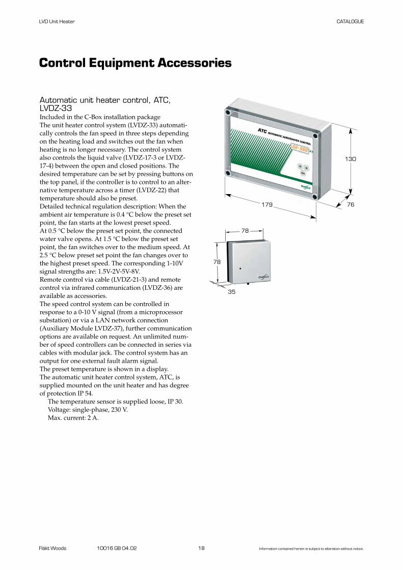
Automatic unit heater control, ATC,LVDZ-33Included in the C-Box installation packageThe unit heater control system (LVDZ-33) automati-cally controls the fan speed in three steps dependingon the heating load and switches out the fan whenheating is no longer necessary. The control systemalso controls the liquid valve (LVDZ-17-3 or LVDZ-17-4) between the open and closed positions. Thedesired temperature can be set by pressing buttons onthe top panel, if the controller is to control to an alter-native temperature across a timer (LVDZ-22) thattemperature should also be preset.Detailed technical regulation description: When theambient air temperature is 0.4 °C below the preset setpoint, the fan starts at the lowest preset speed. At 0.5 °C below the preset set point, the connectedwater valve opens. At 1.5 °C below the preset setpoint, the fan switches over to the medium speed. At2.5 °C below preset set point the fan changes over tothe highest preset speed. The corresponding 1-10Vsignal strengths are: 1.5V-2V-5V-8V.Remote control via cable (LVDZ-21-3) and remotecontrol via infrared communication (LVDZ-36) areavailable as accessories.The speed control system can be controlled inresponse to a 0-10 V signal (from a microprocessorsubstation) or via a LAN network connection(Auxiliary Module LVDZ-37), further communicationoptions are available on request. An unlimited num-ber of speed controllers can be connected in series viacables with modular jack. The control system has anoutput for one external fault alarm signal. The preset temperature is shown in a display.The automatic unit heater control system, ATC, issupplied mounted on the unit heater and has degreeof protection IP 54.
The temperature sensor is supplied loose, IP 30.Voltage: single-phase, 230 V.Max. current: 2 A.
130
76179
78
78
35

Fläkt Woods 10016 GB 04.02 19 Information contained herein is subject to alteration without notice.
LVD Unit Heater CATALOGUE
Valve with actuator, forwater, open/closed,LVDZ-17-4, For use together with the following:LVDZ-15-4, LVDZ-18-3, LVDZ-19-3,LVDZ-33, or LVDZ-34.The valve opens/closes the liquidcircuit.Valve housing is made of red brass.Temperature range: 2 – 110 °C, kvs4.0. Motorized valve with built-inanti-frost function. Opening time: 10 seconds.Max. permissible ambient temper-ature: 50 °C. Adapters for fitting torelevant water connection aresupplied. Threaded pipe connec-tion for further pipe routing. Length of cable: 1.5 m.
Degree of protection: IP 54.Voltage: single-phase, 230 V.
Valve with thermal actua-tor, for water,open/closed, LVDZ-17-3 For use together with the follow-ing:LVDZ-15-4, LVDZ-24-3,LVDZ-18-3, LVDZ-19-3,LVDZ-25-3, LVDZ-29, LVDZ-33, orLVDZ-34. The valve opens/closesthe circuit. The valve housing ismade of red brass. Temperaturerange: 2 – 110 °C, kvs 4.0. Thermalactuator. Dead (non-energised)valve is open. Max. permissible ambient temper-ature: 50 °C. Adapters for fitting torelevant water connection aresupplied. Threaded pipe connec-tion for further pipe routing. Length of cable: 1.5 m.
Degree of protection: IP 40.Voltage: single-phase, 230 V.
Control Equipment Accessories
66DN 20
120
DN 20
66
125
Speed selector switchLVDZ-14For manual switching from highto medium speed, low andswitching out.Plastic casing for wall-mounting.
Degree of protection: IP 42Voltage: single-phase, 230 V.Max current: 10 A.
64
64
5575

Fläkt Woods 10016 GB 04.02 20 Information contained herein is subject to alteration without notice.
LVD Unit Heater CATALOGUE
Control Equipment Accessories
Room thermostat for fanoperation, LVDZ-19-3For switching in and switching outthe unit heater.The thermostat can also beconnected to theLVDZ-28, LVDZ-24-3 andLVDZ-25-3. An LVDZ-17-3 orLVDZ-17-4 valve with actuatorcan be connected to the thermo-stat. Make sure that the correctfunction is obtained, dependingon the type of actuator.
Degree of protection: IP 54.Voltage: single-phase, 230 V.Max. current: 16 A.
Remote control for auto-matic temperature control,LVDZ-21-3 for LVDZ-29
Remote control for auto-matic temperature control,LVDZ-21-4 for LVDZ-33For remote control of the LVDZ-29or LVDZ-33 Automatic unit heatercontrol system. The desired setpoint temperature can be set on thecontroller. Automatic or manualoperation as well as switched-offposition can be selected by pressingthe appropriate button. For manualoperation, fixed low, medium orhigh fan speeds can be selected. The set point, fan speed andtemperature settings can be read inthe display.A 5 m long connection cord withconnector for connection to the unitheater control system is supplied. Extensions are available for length-ening the connection cord to 100 m.
Degree of protection: IP30.
57
130
65
49
78
78 35
Room thermostat for fanoperation, LVDZ-18-3 For switching in and switchingout the unit heater.The thermostat can also beconnected to theLVDZ-28, LVDZ-24-3 andLVDZ-25-3. An LVDZ-17-3 orLVDZ-17-4 valve with motorizedactuator can be connected to thethermostat. Make sure that thecorrect function is obtained,depending on the type of actuator.
Degree of protection: IP 30.Voltage: single-phase, 230 V.Max. current: 16 A.
3578
78

Fläkt Woods 10016 GB 04.02 21 Information contained herein is subject to alteration without notice.
Transformer,LVDZ-25-3For obtaining a lower fixed speedthan the factory-preset speed.If current is to be supplied to sever-al unit heaters, select the ATDZ-28.The transformer has a plasticcasing. The transformer has provi-sion for connecting an LVDZ-17-3or LVDZ-17-4 valve, LVDZ-18-3 orLVDZ-19-3 room thermostat and anLVDZ-22-3 timer.
For particulars of the connectionoptions, see the appropriate instal-lation example.
Degree of protection: IP 54.Voltage: single-phase, 230 V.Max. current: 2 A.
125100
175
LVD Unit Heater CATALOGUE
Speed selector switch,LVDZ-24-3For manual switching betweenthree preset speeds, low – medium– high, as well as switched-off. Theselector switch has a plastic casingand can be fitted e.g. to a wall. Theswitch has provision for connectingan LVDZ-17-3 valve, LVDZ-18-3 orLVDZ-19-3 room thermostat and anLVDZ-22-3 timer.
For particulars of the connection options, see the appropriate instal-lation example.
Degree of protection: IP 54.Voltage: single-phase, 230 V.Max. current: 2 A.
Control Equipment Accessories
125100
175
Timer for automatictemperature control, LVDZ-22-3 For switching between presetdaytime and night time tempera-tures in the LVDZ-29/-33(Automatic unit heater control).The timer enables switching to asecond preset temperature in theAutomatic unit heater controlsystem. This makes it possible toobtain a lower temperature in thepremises e.g. at night and duringweekends to save on electricpower. The timer can also be connectedto the LVDZ-24-3 and LVDZ-25-3and LVDZ-28.
Max. current: 10 A.
3546
66
2520
65 6085

Fläkt Woods 10016 GB 04.02 22 Information contained herein is subject to alteration without notice.
LVD Unit Heater CATALOGUE
Control Equipment Accessories
Speed selector switch,LVDZ-28For obtaining a lower fixed speedthan the factory-preset speed, formax. 6 unit heaters. The trans-former has a plastic casing. Hasprovision for connecting anLVDZ-17-3 valve, LVDZ-18-3 orLVDZ-19-3 room thermostat andan LVDZ-22-3 timer to the trans-former.
For particulars of the connec-tion options, see the appropriateinstallation example.
Degree of protection: IP 54.Voltage: single-phase, 230 V.Max. current: 9 A.
360
260
185
Junction box,LVDZ-30Junction box for arranging the elec-trical wiring to the unit heater.
If the junction box is orderedtogether with the LVDV, it issupplied fitted to the unit, whichsimplifies electrical installation.
Degree of protection: IP 44.Voltage: single-phase, 230 V.
Temperature sensor, RGhumidity,LVDZ-35-1, LVDZ-35-2Temperature sensor for humidenvironments. Can be usedinstead of the temperature sensorsupplied on the following controlsystems, if needed:
If the ATC LVDZ-29 Automaticunit heater control is used, specifythe LVDZ-35-1.
If some other Automaticfan/unit heater control is used,specify the LVDZ-35-2.
Degree of protection: IP 54.
40
51
5083
80
40

Fläkt Woods 10016 GB 04.02 23 Information contained herein is subject to alteration without notice.
LVD Unit Heater CATALOGUE
Auxiliary module fornetwork connection,LVDZ-37Automatic unit heater control,ATC, can be individually remote-controlled or controlled in a group. All the settings can be read andaltered.If several ATC Automatic unitheater control units are to becontrolled from a master system,the module has a universal inter-face for other communicationprograms, such as Modbus,Profibus and RS 485.
Operating voltage: 10-30 V.Aquotation will be submitted on
request.
Control Equipment Accessories
Remote control, infrared,LVDZ-36Battery-powered control unitincluding wall mounting bracketfor remote control of the LVDZ-33Automatic unit heater control. Thedesired set point is preset on thecontrol unit. Automatic or manual operationand switched-off position can beselected by pressing the appropriatebutton. If the unit heater is to be operatedmanually, fixed low, medium orhigh fan speed can be selected.The preset temperature set point,fan speed and present temperaturecan be read in the display.
Degree of protection: IP30.
33
140
63
83
80
40

Fläkt Woods 10016 GB 04.02 24 Information contained herein is subject to alteration without notice.
Example 1. Workshop Halls, Warehouses1. Start by measuring the floor surface of the premises.
Assume a warehouse with a floor surface of 10 m x 24 m = 240 m2.
2. Then estimate the ceiling height.For our example, we estimate a ceiling height of 4 m,which means that we can use the chart on the next page.
3. Then estimate the nature of the building and the typeof heating used. The warehouse is relatively new with good insulation,but totally lacks basic heating. Select 80 W/m2 from thechart below.
4. Estimate the capacity required.In this case, the capacity required will be 240 x 80 =19.2 kW. Select the number of unit heaters needed.As a rule of thumb, each unit heater can heat 100 m2
(10 m x 10 m). In this case, 3 units are therefore needed. We then will have 6.4 kW per unit heater.
5. Then plot the appropriate water temperature andinlet air temperature in the relevant table for heatingon pages 26 and 28. We intend to use 55–35 °C water, and maintain about 20 °C in the premises. We select three LVDV-40-1 units, which, at the given values, will each provide 6.5 kW operating at 900 r/minand meet our requirements. Atotal capacity of 19.5 kW.
6. Motor.We select a single-phase, 230 V motor for simple instal-lation. Should boosted capacity be required, the motorcan easily be re-switched to a higher speed.
7. Select accessories required.We included three LVDZ-04-40 discharge air devices to ensure that the discharged warm air will reach the lower occupied zone. We also select one LVDZ-18-3 room thermostat per air heater for maintaining uniform temperature in the premises.Our purchase list will then be: Three LVDV-40-1Three LVDZ-04-40Three LVDZ-18-3
Example 2. Shop Entrances, Doorways1. Start by measuring the volume of the entrance.
Assume an entrance with a floor surface of 3 m x 4 m and a 3 m high ceiling.The volume will then be 3 m x 4 m x 3 m = 36 m3.
2. Then use the key figure 200 W/m3 to calculate the capacity requiredThe capacity required will then be 36 x 200 = 7.2 kW.
3. Then plot the appropriate water temperature in thetable on page 28, and read the capacity at an inlet airtemperature of 20 °C, which is advisable.In this case, we will use 70–40 °C water.
4. The size of unit and the fan motor speed can be obtained from the table.To keep the sound level low, 700 or 900 r/min is advisable.We select a size 40 unit with the fan motor operating at 670 r/min which provides 7.9 kW.
5. Motor.We select a single-phase, 230 V motor for simple instal-lation. Should boosted capacity be required, the motorcan easily be re-switched to a higher speed.
6. Select the accessories required.We intend to mount the air unit in the ceiling and there-fore need a suspension rod set. Our purchase list will then be:One LVDV-40-1One LVDZ-03
CapacityrequiredW/m2
(max 5 m highceiling)
LVD Unit Heater CATALOGUE
Sizing
None
Basicheating
Exists
Good Insulationbuildning
Poor
100
80
40
60
None
Exists
Building insulation
Poor
Basicheating
Good

Fläkt Woods 10016 GB 04.02 25 Information contained herein is subject to alteration without notice.
LVD Unit Heater CATALOGUE
Installation Particulars
10-15 m
10-15 m
10-15 m
10-15 m5m
Suspended from the ceiling on suspension rods
Mounting against the ceiling

Fläkt Woods 10016 GB 04.02 26 Information contained herein is subject to alteration without notice.
LVD Unit Heater CATALOGUE
Effekttabell
1,4 m3/s46 kW
0,94 m3/s36 kW
0,93 m3/s35 kW
0,73 m3/s30 kW
0,63 m3/s27 kW
0,63 m3/s22 kW
0,42 m3/s17 kW
0,6 m3/s22 kW
0,42 m3/s17 kW
0,34 m3/s15 kW
Effekt
Vertikalkastlängd, m
Vertikalkastlängd, m
StorlekVarvtal, rpm 570 670 900 920 1410 Effekt
1
0
2
3
4
5
1
0
2
3
4
5
6
7
50–1 50–6 50–4
StorlekVarvtal, rpm 670 900 1300 920 1380
45Ljudnivå, dB(A) 52 62 52 63
49Ljudnivå, dB(A) 53 61 60 69
40–1 40–6 40–4
Översiktsdiagram för snabbval
Capacity Chart
Survey Chart for Quick Selection
SizeSpeed, rpm Capacity
VerticalThrow, m
Sound level, dB(A)
SizeSpeed, rpm Capacity
VerticalThrow, m
Sound level, dB(A)

Fläkt Woods 10016 GB 04.02 27 Information contained herein is subject to alteration without notice.
LVD Unit Heater CATALOGUE
Hot water
80–60 °C 70–40 °C 60–30 °C 55–35 °C
LVDV Speed Airflow Inlet Outlet Outlet Outlet Outletsize air Capacity air Water air Water air Water air Water
temp. temp. flow Capacity temp. flow Capacity temp. flow Capacity temp. flowrpm m3/s °C kW °C l/s kW °C l/s kW °C l/s kW °C l/s
40-1 670 0,34 16,0 52,9 0,19 11,1 38,4 0,09 7,8 29,5 0,06 8,8 32,2 0,11900 0,42 18,5 50,3 0,22 12,7 36,5 0,10 8,9 28,2 0,07 10,1 30,7 0,12
1300 0,60 23,7 45,1 0,28 16,1 33,0 0,13 11,2 25,6 0,09 12,8 28,0 0,15
40-6 920 0,42 18,4 50,4 0,22 12,6 36,6 0,10 8,9 28,2 0,07 10,1 30,8 0,12
40-4 1380 0,63 24,2 44,6 0,29 16,4 32,6 0,13 11,4 25,4 0,09 13,1 27,8 0,16
50-1 570 0,63 +10 29,4 53,0 0,35 20,1 38,2 0,16 14,1 29,1 0,11 16,1 32,1 0,19670 0,73 32,9 51,0 0,39 22,4 36,7 0,18 15,7 28,2 0,13 17,9 31,0 0,21900 0,93 38,8 47,7 0,46 26,2 34,4 0,21 18,3 26,4 0,15 20,9 29,2 0,25
50-6 920 0,94 39,1 47,5 0,47 26,4 34,3 0,21 18,4 26,4 0,15 21,1 29,1 0,25
50-4 1410 1,40 50,4 39,8 0,61 32,8 29,3 0,26 22,2 23,1 0,18 25,9 25,3 0,31
Capacity Table
Inlet air temperature +10 °C
The temperature of the outlet hot water may vary incomparison to the lower temperature tabulated in thewater temp. range above. The table is applicable to aunit heater with open air discharge. The air density at tihas been taken into account in the calculation of thecapacities (P). The calculation values for air density:+10 °C = 1.25 kg/m3.

Fläkt Woods 10016 GB 04.02 28 Information contained herein is subject to alteration without notice.
Hot water
80–60 °C 70–40 °C 60–30 °C 55–35 °C
LVDV Speed, Airflow Inlet Outlet Outlet Outlet Outletsize air air Water air Water air Water air Water
temp. Capacity temp. flow Capacity temp. flow Capacity temp. flow Capacity temp. flowrpm m3/s °C kW °C l/s kW °C l/s kW °C l/s kW °C l/s
40-1 670 0,34 14,6 54,2 0,17 9,5 39,5 0,08 6,1 30,2 0,05 7,3 33,4 0,09900 0,42 16,8 51,9 0,20 10,9 37,9 0,09 7,0 29,3 0,06 8,3 32,2 0,10
1300 0,60 21,5 47,2 0,26 13,8 34,9 0,11 8,8 27,4 0,07 10,5 29,9 0,13
40-6 920 0,42 16,7 51,9 0,20 10,8 37,9 0,09 6,9 29,3 0,06 8,3 32,2 0,10
40-4 1380 0,63 22,0 46,7 0,26 14,1 34,6 0,11 9,0 27,2 0,07 10,8 29,7 0,13
50-1 570 0,63 +15 26,7 54,3 0,32 17,3 39,3 0,14 10,8 29,7 0,09 13,2 33,2 0,16670 0,73 29,9 52,4 0,36 19,2 38,0 0,15 12,0 29,0 0,10 14,7 32,3 0,17900 0,93 35,3 49,5 0,42 22,6 36,2 0,18 14,2 28,0 0,11 17,3 30,9 0,21
50-6 920 0,94 35,6 49,3 0,42 22,8 36,1 0,18 14,3 27,9 0,11 17,4 30,8 0,21
50-4 1410 1,40 46,1 42,0 0,55 28,1 31,4 0,22 17,2 25,1 0,14 21,4 27,5 0,26
LVD Unit Heater CATALOGUE
Capacity table
The temperature of the outlet hot water may vary in com-parison to the lower temperature tabulated in the watertemp. range above. The table is applicable to a unit heaterwith open air discharge. The air density at ti has beentaken into account in the calculation of the capacities (P).The calculation values for air density: +15 °C = 1.23 kg/m3.
Inlet air temperature +15°C

Fläkt Woods 10016 GB 04.02 29 Information contained herein is subject to alteration without notice.
LVD Unit Heater CATALOGUE
Capacity table
Hot water
80–60 °C 70–40 °C 60–30 °C 55–35 °C
LVDV Speed Airflow Inlet Outlet Outlet Outlet Outletsize air air Water air Water air Water air Water
temp. Capacity temp. flow, Capacity temp. flow, Capacity temp. flow, Capacity temp. flow, rpm m3/s °C kW °C l/s kW °C l/s kW °C l/s kW °C l/s
40-1 670 0,34 13,2 55,5 0,16 7,9 40,5 0,06 4,3 30,7 0,04 5,7 34,4 0,07900 0,42 15,1 53,4 0,18 9,2 39,3 0,07 4,8 29,8 0,04 6,5 33,6 0,08
1300 0,60 19,3 49,1 0,23 11,5 36,6 0,09 6,2 28,7 0,05 8,3 31,8 0,10
40-6 920 0,42 15,1 53,4 0,18 9,1 39,4 0,07 4,8 29,8 0,04 6,5 33,7 0,08
40-4 1380 0,63 +20 19,8 48,7 0,24 11,8 36,4 0,09 6,3 28,6 0,05 8,4 31,6 0,10
50-1 570 0,63 24,1 55,6 0,29 14,3 40,2 0,11 8,3 31,4 0,07 10,3 34,2 0,12670 0,73 26,9 53,8 0,32 16,1 39,4 0,13 8,6 30,1 0,07 11,5 33,6 0,14900 0,93 31,7 51,2 0,38 18,8 37,7 0,15 9,5 28,7 0,08 13,5 32,5 0,16
50-6 920 0,94 32,0 51,0 0,38 18,9 37,6 0,15 9,6 28,7 0,08 13,6 32,5 0,16
50-4 1410 1,40 41,6 44,3 0,50 23,4 33,7 0,19 11,6 26,8 0,09 16,6 29,7 0,20
The temperature of the outlet hot water may vary incomparison to the lower temperature tabulated in thewater temp. range above. The table is applicable to aunit heater with open air discharge. The air density at tihas been taken into account in the calculation of thecapacities (P). The calculation values for air density:+15 °C = 1.20 kg/m3.
Inlet air temperature +20°C

Fläkt Woods 10016 GB 04.02 30 Information contained herein is subject to alteration without notice.
LVD Unit Heater CATALOGUE
Pressure drop on the water side
Technical data
(With the valve fitted ∆prtot = ∆prtemper + ∆prvalve)
90°–70°
70°–40°
90°–
70°
60°–30°
70°–40
°
60°–30
°
Luftflöde, q (m3/s)
Vär
mee
ffekt
, P (kW
)
60
50
40
30
20
10
5
30,5 1,0 1,5
Temp. värmevatten
LUFTVÄRMARE LVDVIng.lufttemperatur 15°CMotor varvtal min 600 rpm
LVDV–50
LVDV–40
LVDV-
40
LVDZ-
17-3
(ven
til)
LVDV-
50
Vattenflöde, l/s
Tryc
kfal
l, kP
a
20
10
5
10,05 0,1 0,5 1,0
Heat capacity
Hot water temp.
LVDV UNIT HEATERInlet air temperature 15 °CMin. motor speed 600 rpm
Pre
ssur
e dr
op, k
Pa
Water flow, l/s
LVDZ-
17-3
(valve
)
Hea
t cap
acity
, P (k
W)
Air flow, q (m3/s)

Fläkt Woods 10016 GB 04.02 31 Information contained herein is subject to alteration without notice.
LVD Unit Heater CATALOGUE
Sound level, sound power level Throw, vertical air discharge
Technical data
Tolerance: ± 2 dB1) Sound level at a distance of 5 meters, Q = 2, absorption area = 200 m2 Sabine.2) Sound power in accordance with ISO 3744
The specified throw is applicable to a supply air tem-perature of +40°C and an indoor temperature of +18°C.The air deflector is fitted horizontally.The premises are completely free of disturbance fromair draughts and nearby furnishings. L0,2= the perpendicular distance from the unit heater
to air velocity v = 0.2 m/s.
Size Speed Sound Sound Linear sound power, dB,level, power octave band, centre frequency, Hz1) 2)
LVDV r/min dB(A) dB(A) 125 250 500 1000 2000 4000 8000
40-1 670 45 63 63 64 61 59 52 46 3440-1 900 52 68 68 69 66 64 58 52 4140-1 1300 62 78 77 78 75 73 68 63 54
40-6 920 52 68 66 69 66 63 57 51 41
40-4 1380 63 79 80 79 76 74 69 64 56
50-1 570 49 65 66 65 64 60 54 46 3750-1 670 53 69 71 69 68 65 59 51 4250-1 900 61 77 79 80 75 71 66 58 51
50-6 920 60 76 78 76 75 72 66 60 52
50-4 1410 69 85 86 84 84 80 75 71 66
l0,2
l0,2
Vertical throw, l0,2Size Speed without LVDZ-04 with LVDZ-04aa-b r/min m m
670 2,5 4,540-1 900 3,0 5,5
1300 4,0 8,0
40-6 920 3,0 5,5
40-4 1380 4,5 8,5
570 3,0 6,050-1 670 3,5 7,0
900 4,5 8,5
50-6 920 4,5 9,0
50-4 1410 6,5 12,5

Fläkt Woods 10016 GB 04.02 32 Information contained herein is subject to alteration without notice.
LVD Unit Heater CATALOGUE
Motor DataLVDV – For hot water
Operating DataMax. ambient air temperature around motor = +70 °C.Max. operating pressure 1.6 MPa.Max. operating temp. 100 °C.Leakage tested.
Technical Data
The accessories LVDZ-15-4, LVDZ-24-3, LVDZ-25-3,LVDZ-28, LVDZ-29 and LVDZ-33 include a transformerwhich, besides 230 V output current, has five lower volt-ages for lower speed. The LVDZ-15-4, LVDZ-29 andLVDZ-33 operate with 3 different voltages. These acces-sories are factory-wired making it possible to obtain theappropriate speed for each step.The table above shows the factory-wired voltages andcorresponding speed. If for some reason it is desirable toalter the speeds, this can be done by reconnecting theflexible connections on the transformer.
Detailed wiring diagrams for motors and accessoriesare provided in the installation, operation and mainte-nance instructions for the LVDV.
Speed with Voltage Control
= supplied speed
Code Speed, Rated Rated current (A), 50 HzLVDV- output,aa-b r/min kW 230 V, 1-phase 400 star
670 0,740-1 900 0,15 1,0 –
1300 1,50
40-6 920 0,18 – 0,740-4 1380 0,18 – 0,7
570 0,750-1 670 0,17 1,2 –
900 1,7
50-6 920 0,18 – 0,7
50-4 1410 0,55 – 1,5
The speeds specified in bold type are for the delivery version.
LVDV-40-1 LVDV-50-1
230 V 1300 900150 V 980 770130 V 820 690115 V 690 610100 V 560 51080 V 380 370

Fläkt Woods 10016 GB 04.02 33 Information contained herein is subject to alteration without notice.
LVD Unit Heater CATALOGUE
All measurements in mm
Dimensions and Weights
20
F
E
N
øM
30ø 15
100
LVDZ-33
175
Ansl. K
AD
C B
Ansl. K
SizeA B C D E F M N
Weight, Volume, K Nom. kg litres pipe size
LVDV-40 930 600 635 760 155 345 406 190 31 1,6 DN 20
LVDV-50 1130 700 735 960 220 380 514 160 45 3,8 DN 25
Conn. K
Conn. K
Fläkt Woods 10016 GB 04.02 34 Information contained herein is subject to alteration without notice.
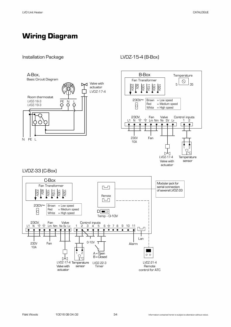
Installation Package LVDZ-15-4 (B-Box)
Wiring Diagram
LVD Unit Heater CATALOGUE
A-Box, principschema
PE N L
N PE L
RumstermostatLVDZ-18-3 LVDZ-19-3
Ventil medställdonLVDZ-17-4
Fan Transformer
TemperatureB-Box
L1 N
5 35
230V10A
Fläkt
Brown = Low speedRed = Medium speedWhite = High speed
LVDZ-17-4Ventil med
ställdon
Temperatur-givare
Lm Nm Nv Lv 1 2
1 2
°C
230V~
230V Fan Valve Control inputs
115V
100V
80V
230V
130V
150V
SV
Fan Transformer
C-Box
D
Remote
Moduljackför seriekoppling av flera LVDZ-33
Temp - 0-10V
L1 N
230V10A
Fläkt 0-10V
Brown = Low speedRed = Medium speedWhite = High speed
LVDZ-17-4Ventil med
ställdon
Temperatur-givare
LVDZ-22-3Tidur
LVDZ-21-4Fjärrstyrning
för ATC
Lm Nm Nv Lv 1 2
1 2
°C
3 4 5 6
230V~
230V Fan Valve Control inputs
150V
130V
115V
100V
80V
230V
A = ÖppenB = Stängd
7 8 9 10 11
Larm
Lan
Sv
LVDZ-33 (C-Box)
Basic Circuit Diagram
Room thermostat
Valve with actuator
Fan
Valve withactuator
Temperaturesensor
Fan
Modular jack forserial connectionof several LVDZ-33
Valve withactuator
Temperaturesensor
A = OpenB = Closed
Timer
Alarm
Lan
Remotecontrol for ATC

Fläkt Woods 10016 GB 04.02 35 Information contained herein is subject to alteration without notice.
LVD Unit Heater CATALOGUE
Wiring Diagram
Reglering med rumstermostatoch ventilATDZ-17-3
PE N L
N PE L
RumstermostatLVDZ-18-3LVDZ-19-3
Ventil medställdonLVDZ-17-3
Control with Room Thermostat and LVDZ--17-3Valve with Actuator, Basic Circuit Diagram
3-step switch, LVDZ-24-3
Transformer, LVDZ-25-3
Brown = Low speedRed = Medium speedWhite = High speed
Fan Transformer
Fan speed
1
1
2
2
3
3
4
230V10A MotorLVDZ-17-3
Ventil medställdonLVDZ-18-3
5 6 7 8 9 10 11 12230 V Valve Fan
150V
130V
115V
100V
80V
230V
0 31 2
Rumstermostat
Fan Transformer
1 2 3 4
230V10A MotorLVDZ-17-3
Ventil medställdon
5 6 7 8 9 10 11 12230 V Valve Fan
15
0V
13
0V
11
5V
10
0V
80
V
23
0V
1
2 3
LVDZ-18-3Rumstermostat
Room thermostat,
Valve withactuator,
Room thermostat,
Valve withactuator,
Room thermostat,
Valve withactuator,

Fläkt Woods 10016 GB 04.02 36 Information contained herein is subject to alteration without notice.
W2U1
U2V1
V2W1
T1
T2
t°
230 VAC
0
3
L
N
12
1112
910
78
56
34
12
1
1
2
2
3
3
4
5
6
1
5
4
3
2
6
0 1 2 31234
56
78
910
1112
LVDZ-14 Speed switch
Wiring Diagram
LVD Unit Heater CATALOGUE
Pos. 1 = Low speedPos. 2 = Medium speedPos. 3 = High speed
Speed switch
Connect jumpers on installation
Fan motor
NB! No closing links atU2–V1 and U1–W2 forthis connection.

Fläkt Woods 10016 GB 04.02 37 Information contained herein is subject to alteration without notice.
LVD Unit Heater CATALOGUE
Wiring Diagram
LVDZ--22-3 Timer
3
L
1 2
M
LVDZ-22-3
L1
N
Ω
L1
N
N
C1
LVDZ--18-3Room thermostat
1
2 3
LVDZ-18-3
LVDZ--19-3Room thermostat
4 2 1
c

Fläkt Woods 10016 GB 04.02 38 Information contained herein is subject to alteration without notice.
LVDZ—29 Automatic unit heater regulation, ATC
Wiring Diagram
LVD Unit Heater CATALOGUE
A
B
C
1234
56
Inkom-mande styr
12 C
Enhe
t 9
Enhe
t 1
LF
NF
SV
Fläktmotor 2
GTK
Ventil medställdonLVDZ-17-3
Fläktmotor 9
Kopplingsdosa alt.KopplingsenhetLVDZ-30
LVDZ-29
FS3FS2FS1N230
150V130V115V100V
80VN
230V
FjärrstyrningLVDZ-21-3
TidurLVDZ-22-3A=ÖppenB=Stängd
Temperaturgivare
N
L1
Option
Inkommandematning230 V, 10 A
Installeras via säkerhetsbrytare
GTK
Ventil med ställdonLVDZ-17-3
Fläktmotor 1
Fläktmotor 3
Fläktmotor 4
Fläktmotor 5
Fläktmotor 6
Temperatur
Temperatur
Fjärrstyrning
Fläktmotor 7
Fläktmotor 8Fläkttrans-formator
LF
NF
SV
Fan transformer
Temperature
Temperature
Remote control
Controlinput
Unit 1
Unit 9
Fan motor 8
Fan motor 7
Fan motor 6
Fan motor 5
Fan motor 4
Fan motor 3
Fan motor 2
Junction box alt.LVDZ-30 switch
LVDZ-17-3valve withactuator
Fan motor 9
LVDZ-17-3 valvewith actuator
Fan motor 1
LVDZ-21-3remote control
LVDZ-22-3 timerA=OpenB=Closed
Temperature sensor
230 V, 10 Apower supply
To be wired acrossa safety switch

Fläkt Woods 10016 GB 04.02 39 Information contained herein is subject to alteration without notice.
LVD Unit Heater CATALOGUE
Wiring Diagram
3-phase, 400 VNominal speed, star-coupled
Medium speedSingle-phase, 230 V
Low speedSingle-phase, 230 V
High speedSingle-phase, 230 V
W2
U1
U2
V1
V2
W1 T1 T2
N L
230 VAC
t°
W2
U1 T1 T2
U2
V1
V2
W1
N L
230 VAC
t°
W2
U1
U2
V1
V2
W1 T1 T2
230 VAC
N L
t°
W2
U1
U2
V1
V2
W1
3 x 400 VAC

Fläkt Woods 10016 GB 04.02 40 Information contained herein is subject to alteration without notice.
LVD Unit Heater CATALOGUE
Product code
Installation PackageA-box, size 40 LVDV-40-1-AA-box, size 50 50-1-A
B-box, size 40 LVDV-40-1-BB-box, size 50 50-1-B
C-box, size 40 LVDV-40-1-CC-box, size 50 50-1-C
Standard VersionUnit Heater LVDV-aa-b
Size (aa)40, 50
Motor (b)1 = single-phase, 230 V4 = 3-phase, 400 V, 4 poles6 = 3-phase, 400 V, 6 poles
AccessoriesSuspension rod set LVDZ-03
Air discharge device LVDZ-04-bb
Size (bb)40, 50

Fläkt Woods 10016 GB 04.02 41 Information contained herein is subject to alteration without notice.
LVD Unit Heater CATALOGUE
Product Code
Control EquipmentAutomatic fan control LVDZ-15-4FHC-1, simpleIncluding sensor to IP 30 for wall mounting.Supplied separately. Single-phase, 230 V. Max 2 A.
Automatic fan control LVDZ-34FHC-3, simpleIncluding sensor to IP 30 for wall mounting.Supplied separately. 3-phase, 400 V. Max 2 A.
Automatic unit heater control LVDZ-29ATC, advancedIncluding sensor IP 30 for wall mountingSupplied separately. Single-phase, 230 V. Max 9 A.
Automatic unit heater control LVDZ-33ATC, advancedIncluding sensor to IP 30 for wall mounting.Mounted on unit. Single-phase, 230 V. Max 2 A.
Accessories for Control EquipmentSpeed switch LVDZ-14Manual 3-step for single-phase, 230 V. 10 Amotor.
Speed switch LVDZ-24-3Manual 3-step for single-phase, 230 V. 2 Amotor.
Speed switch LVDZ-28Manual 3-step for single-phase, 230 V. 9 Amotor.
Valve with thermal actuator LVDZ-17-3Open/closed.Single-phase, 230 V.
Valve with actuator LVDZ-17-4Open/closed. Quick-actionSingle-phase, 230 V.
Room thermostat LVDZ-18-3On/off, single-phase, 230 V. IP 30.
Room thermostat LVDZ-19-3On/off, single-phase, 230 V. IP 54.
Remote control for LVDZ-29 Automatic LVDZ-21-3unit heater control.
Remote control for LVDZ-33 Automatic LVDZ-21-4unit heater control.
Remote control, infrared LVDZ-36
Timer LVDZ-22-3Day/night temperature control forAutomatic unit heater control.
Transformer LVDZ-25-3Lower speed: single-phase, 230 V motor.
Connection box LVDZ-30
Temperature sensor for LVDZ-29 LVDZ-35-1Automatic unit heater regulation. IP 54.
Temperature sensor for LVDZ-35-2LVDZ-15-4,-33, -34 Automatic fan, unit heater controlIP 54.
Auxiliary module for network LVDZ-37

Fläkt Woods 10016 GB 04.02 42 Information contained herein is subject to alteration without notice.
LVD Unit Heater CATALOGUE
Spare PartsFan impeller, for size 40 LVDV-99-01-5
Fan impeller, for size 50 LVDV-99-01-6
Motor for size 40 LVDV-99-02-12Single-phase, 230 V, 3 speeds.
Motor for size 40 LVDV-99-02-143-phase, 400 V, 4 poles.
Motor for size 40 LVDV-99-02-163-phase, 400 V, 6 poles.
Motor for size 50 LVDV-99-02-13Single-phase, 230 V, 3 speeds.
Motor for size 50 LVDV-99-02-153-phase, 400 V, 6 poles.
Motor for size 50 LVDV-99-02-173-phase, 400 V, 4 poles.
Safety guard, for size 40 LVDV-99-03-3
Safety guard, for size 50 LVDV-99-03-4
Heating coil, for size 40 LVDV-99-04-1
Heating coil, for size 50 LVDV-99-04-2
Product Code
Fläkt Woods 10016 GB 04.02 43 Information contained herein is subject to alteration without notice.
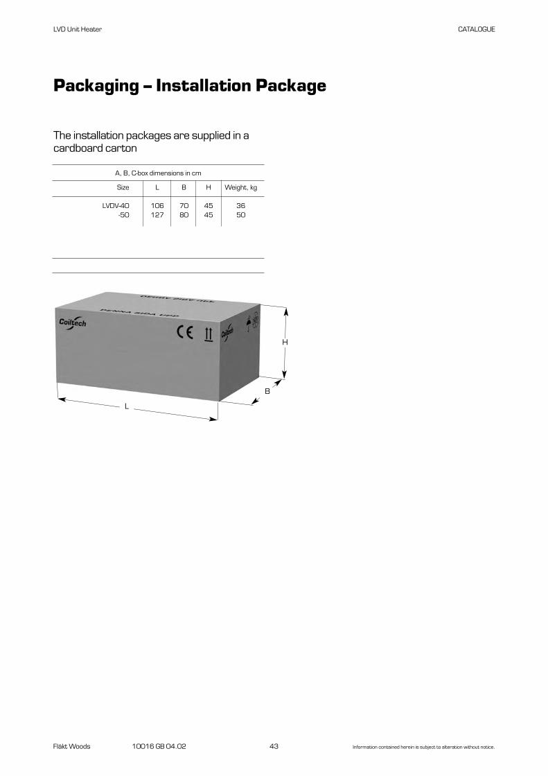
Size L B H Weight, kg
LVDV-40 106 70 45 36-50 127 80 45 50
LVD Unit Heater CATALOGUE
The installation packages are supplied in acardboard carton
Packaging – Installation Package
A, B, C-box dimensions in cm
L
H
B

We Bring Air to Life
Fläkt Woods is a globalleader in air management.We specialise in the designand manufacture of a widerange of air climate and airmovement solutions. Andour collective experienceis unrivalled.
Our constant aim is toprovide systems thatprecisely deliver requiredfunction and performance,as well as maximise energy efficiency.
Fläkt Woods is providing solutions for ventilation and air climate for buildings as well as fan solutions for Industry and Infrastructure.
Solutions for all your air climate and air movement needs
Air Handling Units (AHUs)Modular, compact and smallAHU units. Designed to ensureoptimisation of indoor air quality,operational performance andservice life.
Air Terminal Devices and DuctsSupply and exhaust diffusers andvalves for installation on walls, ceiling or floor are all included in our large range and fit all types of applications.
Chilled BeamsActive induction beams forventilation, cooling and heating,and passive convection beamsfor cooling. For suspended orflush-mounted ceiling installation –and multi-service configuration.With unique Comfort Control andFlow Pattern Control features.
Residential ventilationA complete range of products forresidential ventilation. Consists ofventilation units, exhaust air fans and cooker hoods designed to optimise indoor comfort and save energy. Energy recoveryDessicant-based product and sys-tems that recover energy, increase ventilation and control humidity.
FansAdvanced axial, centrifugal andboxed fans for general and specialist applications. Comprehensive range including high temperature and ATEX compliant options. Engineered for energy efficiency andminimised life cycle cost.
ChillersAir-cooled and water-cooled chillers with cooling capacity up to 1800 kW. Designed tominimise annual energy consumption in all types of buildings.
Controls and drivesVariable speed drives and controlsystems, all tested to ensure totalcompatibility with our products.Specialist team can advise on energy saving and overall systemintegration.
Acoustical productsA complete line of sound attenuating products, including rectangular and round silencers. Media Free silenc-ers, custom silencers and acoustic enclosure panels.
10016 G
B 2
01204 c
onde
sign
tel
esko
p ab
+4
6 (0
)36
-30
83
80
Fläkt Woods Group SA18, avenue Louis Casaï, CH-1209 Geneva, SwitzerlandTel. +41 22 309 3800email [email protected] www.flaktwoods.com
See global web site for internationalsales offices www.flaktwoods.com