lv 02)/2ª4/ª/0%2!4).'ª4//, 2%!$ª4()3ª-!.5!,ª warning! · 2%!$ª4()3ª-!.5!,ª ... the lv...
TRANSCRIPT

Toronto, Ontario M3J 2C6
Tel: 416.631.9400
Fax: 416.631.9426
E-mail: [email protected]
Web: www.ucanfast.com
OPERATOR'SINSTRUCTION
MANUAL
WARNING!
SEMI-AUTOMATIC LOW VELOCITYFASTENING TOOL WITH POWER
ADJUSTMENT DIAL
LV 365
Rev. 1/10
LV 365S/N. 00100

1
TABLE OF CONTENTS
Tool handling and use ...................................................................... 2-3
Limitations of use ............................................................................. 3-4
Maintenance ....................................................................................... 5
Operation ......................................................................................... 6-7
Assembly ............................................................................................ 7
How to change the piston and sleeve................................................. 8
Cleaning and maintenance ................................................................. 9
Deluxe equipment ............................................................................. 10
Parts list and diagram .................................................................. 11-12
Headed fasteners ............................................................................. 13
Fastener penetration guide ............................................................... 13
Replacement parts and repair service .............................................. 13
Training course ............................................................................ 14-21
Warranty ........................................................................................... 22
INTRODUCTION
The LV 365 is designed for speed, convenience, economy and above all...
SAFETY. The LV 365 will give many years of service. To ensure consistent,
trouble-free operation of the LV 365 and to prevent injury, follow the
instructions in this manual for operating, cleaning, and maintaining the tool.
PRIOR TO THE USE OF THIS TOOL, THE OPERATOR SHOULD BEPROPERLY TRAINED BY A QUALIFIED INSTRUCTOR
In this instruction manual you will also find illustrations of the LV 365 as well
as information about cartridges, pistons, and spare parts. If you have
questions which are not addressed in this manual, or if you have special
fastening applications, please contact your nearest UCAN Fastening
Products' Distributor.
TOOL FEATURES
Tool length: 13-5/8" Fastener range up to: 2-1/2 inches
Tool weight: 5.1 lbs. 10 cartridge magazine with
semi-automatic cartridge advance.
2
TOOL HANDLING & USE
1. Operate tool with powder loads and fasteners specified by the
tool manufacturer.
2. Only trained operators may use powder actuated tools.
3. Operate in accordance with the manufacturer's instruction manual
provided with each tool.
4. Wear personal protective gear, including goggles, ear plugs and
helmet. This applies to the tool operator and bystanders in close
proximity to the firing of the tool.
5. Do not use powder actuated tools in explosive or flammable
environments.
6. When the powder actuated tool is used in a confined space,
ensure area is ventilated.
7. Prior to use, the operator shall inspect the tool as specified in the
manual to determine that it is in proper working condition.
Tools found not to be in proper working condition shall be serviced in
accordance with the instruction manual.
8. If a tool is found to be defective, it shall not be used, but shall be
marked "Repair". Makeshift repairs or alterations shall not be made
to any tool. Refer to “maintenance” on page 5.
9. When fastening directly into concrete or steel, use the proper
stabilizer or guard, suited for the application.

TOOL HANDLING & USE cont'd....
10. Under no circumstances shall a loaded tool be left unattended.
11. Tools, whether loaded or not, must not be pointed at any person.
12. The muzzle of the tool must not be depressed by the palm of the
hand.
13. The tool should always be held perpendicular to the work surface while
fastening any material, except for special applications
recommended by and carried out in accordance with specific
practices prescribed by the tool manufacturer.
14. In the event of a misfire, the operator shall continue to hold the tool
firmly against the work surface for a period of not less than 15
seconds, after which time the cartridge shall be ejected. The misfired
cartridge must be removed from the spent power load strip and
disposed of in accordance with local regulations.
LIMITATIONS OF USE
1. Fasteners shall not be driven into very hard or brittle materials
including but not limited to cast iron, glazed tile, hardened steel,
glass block, natural rock, hollow tile, or some types of brick.
2. When the hardness of a substrate or surface is not known, it
shall be tested by using a hand hammer to drive the point of the
fasteners into the surface. If a fastener does not easily penetrate, is
not blunted, and does not fracture the surface, initial test fastenings
shall then be made in accordance with the tool manufacturer's
recommendations. If the point of the fastener does not penetrate the
surface, no attempt shall be made to use the tool on that surface.
3. Fasteners shall not be driven into easily penetrable or crumbly
materials of unknown resistance.
4. Fasteners with a shank diameter of 4.83 mm (0.190 in) or less shall not
be driven into concrete:
a. at a distance closer than 75mm (3 in) from an unsupported
edge, unless written approval from the manufacturer is
obtained prior to undertaking this work.
b. that is less than 65mm (2-1/2 in) in thickness, or three times the
penetration of the fastener shank;
c. at a distance less than 75mm (3 in) from where another fastener
has failed.
3 4
LIMITATIONS OF USE cont'd....
5. Fasteners with a shank diameter of 4.83mm (0.190 in) or less shall not
be driven into steel:
a. that is less than 4.83mm (3/16 in) in thickness;
b. at a distance less than 50mm (2 in) from a weld; and
c. at a distance less than 13mm (1/2 in) from the edge.
6. Fasteners with a shank diameter larger than 4.83mm (0.190 in) shall
not be driven into steel:
a. that is less than 10mm (3/8 in) in thickness;
b. at a distance less than 50mm (2 in) from a weld; and
c. at a distance less than 13mm (1/2 in) from the edge.
7. Fasteners may be driven into masonry walls (brick or block) but shall
not be driven into a corner brick nor a vertical mortar joint.
8. Fasteners shall not be driven directly adjacent to pretensioning or
post tensioning tendons.

MAINTENANCE AND STORAGE
5
1. Clean and lubricate the tool as recommended in the Instruction
Manual.
PROPER MAINTENANCE AND STORAGE OF POWDER ACTUATEDTOOLS IS NECESSARY TO ENSURE CONSISTENT, TROUBLE-FREE
OPERATION AND HELP PREVENT INJURY.
2. Check tools prior to each day's use to ensure they are in proper
working order.
5. Powder actuated tools and cartridges shall be locked in a container
and stored in a safe place when not in use. Only authorized
personnel, trained to use the tool, should have access.
4. Any tool found not in working order should be immediately removed
from service, tagged as "defective" and used again only after being
repaired by a qualified individual. Use only repair/replacement
parts recommended by the tool manufacturer.
3. Replace worn or damaged parts as required.
OPERATION
IMPORTANT: To make successive fastenings,always insert the fastener
before advancing magazine as in illustrations 1 & 2. Overdriving due to
using too strong a cartridge, too short a fastener, or too little resistance in
the base material can result in deformation of the shear clip. If this should
occur, the shear clip must be replaced. Always completely remove
the magazine before disassembly or cleaning of the tool. The magazine
must always be removed from the top of the tool - never from the
handgrip. Your LV365 must always be unloaded before:
- changing any parts (piston, piston sleeve, etc.)
- taking a work break - servicing and cleaning
- storing at the end of the work day.
After removing each magazine, the breech must be inspected for foreign
particles.
1. With the point out, insert fastener into the guide until it is held in place
by the plastic washer.
2. In one movement, pull out the baseplate and piston sleeve to the
stop, then push back again to the stop.
2a. If the movement is stiff, lightly spray the outer surface of the piston
sleeve with lubricant and slide in and out several times.
3. Insert the magazine into the base of the handgrip. Slide the magazine
upwards until it is flush with the bottom of the grip. Always insert
magazine from the bottom of the tool.
4. Press tool firmly and squarely against the work surface and squeeze
trigger.
NOTE: Tool must be perpendicular to work surface for best fastening
results.6
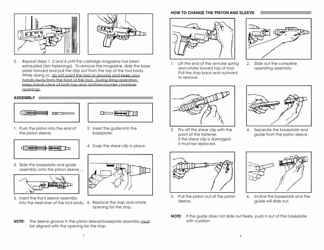
5. Repeat steps 1, 2 and 4 until the cartridge magazine has been
exhausted (ten fastenings). To remove the magazine, slide the base
plate forward and pull the strip out from the top of the tool body.
While doing so, do not point the tool at anyone and keep your
hands away from the front of the tool. During firing operation,
keep hands clear of both top and bottom booster chamber
openings.
ASSEMBLY
1. Push the piston into the end of 2. Insert the guide into the
the piston sleeve. baseplate.
4. Snap the shear clip in place.
3. Slide the baseplate and guide
assembly onto the piston sleeve....
5. Insert the front sleeve assembly
into the steel liner of the tool body. 6. Replace the stop and rotate
opening for the stop.
NOTE: The sleeve groove in the piston sleeve/baseplate assembly must
be aligned with the opening for the stop.
7 8
HOW TO CHANGE THE PISTON AND SLEEVE
1. Lift the end of the annular spring 2. Slide out the complete
and rotate toward top of tool. operating assembly.
Pull the stop back and outward
to remove.
3. Pry off the shear clip with the 4. Separate the baseplate and
point of the fastener. guide from the piston sleeve.
If the shear clip is damaged,
it must be replaced.
5. Pull the piston out of the piston 6. Incline the baseplate and the
sleeve. guide will slide out.
NOTE: If the guide does not slide out freely, push it out of the baseplate with a piston.

CLEANING AND MAINTENANCE
Clean the parts and surfaces with the supplied brushes.
NOTE: ALWAYS clean the tool daily or after approximately 1,000 firings.
Piston Sleeve Piston Guide
Internally and Externally Externally Internally and Externally
Baseplate
Steel LinerInternally and Externally
Internally
Spray all parts with lubricant and wipe o
The driving power is adjusted by means of a knurled wheel on the right side
of the tool. when the indicator is in the rearmost position the greatest driving
power is obtained from a power load. Similarily, when the indicator is moved
to the foremost position the lowest driving power is obtained.
ff excess before reassembling.
NOTE: DO NOT SPRAY the inside of the steel liner or magazine chamber
on the piston sleeve.
9
POWER REGULATION
DELUXE EQUIPMENT
Deluxe kit includes:
LV365
UCAN Fastening Products provides a set of disposable sample ear plugs
with each tool. These are not intended as permanent ear protection.
Cleaning
brushes
Lubricant
spraySafety Goggles
Cleaning clothManual
10
Parts may not be exactly as shown.
Ear Plugs
( Disposable )
Carrying Case
Spare Parts
5
5
LV 365S/N. 00100

LV-365 PARTS KIT
11 12
DescriptionRubber PadCover PlugSpring, Sear Holder Spring FiringFiring Pin NutFiring Pin Return SpringFiring Pin RingFiring PinSear TubeBodySteel LinerStopPiston SleevePistonPiston RingGuideBase PlateTrigger SpringScrew (M6X10)Pin (A4X18)Screw (M16X10)Lever SpringFiring LeverSear SpringSear
Part No.365013650236503
365053650636507 365083650936510365113651236513365143651536516365173651836519365203652136522365233652436525
DescriptionAdvance BarSpring, Advance BarTriggerLever SeatHollow PinThreaded PinScrew (M6X18)Firing Sleeve BarMagazine Catch SpringSteel Ball ( 5)Annular SpringSteel Ball ( 6)Shear Clip
Part No.36526365273652836529365303653136532365333653436535365363653736538
36504
Supporting Angle PieceCirclipPush PinScrew (M3X5)Positioning SpringScrew (M6) Positioning LeverCovering PlateScrew (M5X12)Screw (M5X8)
36539365403654136542365433654436545365463654736548

.300 FLAT-HEADED FASTENERS5/16" FLUTED GUIDE WASHERS
AFH 19 (3/4") AFH 47 (1-7/8")
AFH 25 (1") AFH 57 (2-1/4") AFH 32 (1-1/4") AFH 62 (2-1/2")
AFH 37 (1-1/2")
Knurled for Steel SUPER POINT PINS
AFH 13K (1/2") ASB 13 (1/2") ASB 32 (1-1/4")ASB 19 (3/4")
ASB 47 (1-7/8")
1/4-20 THREADED STUDS
U-14-20/12K 3/4" 1/2"
U-14-20/25 3/4" 1"
CARTRIDGES .27 Calibre StripIn strips of 10 cartridges each:
Description Power level Part# (100)
Red 5 heavy CHS R
FASTENER PENETRATION GUIDE
Soft masonry Cinder-concrete block, etc 1-1/2" penetration
Avg. concrete Poured concrete, etc 1" penetration
Dense concrete Pre-stressed/pre-cast concrete 3/4" penetration
Steel Structural steel, etc 1/2" penetration
REPLACEMENT PARTS AND REPAIR SERVICE
Your UCAN Powder Actuated Tool is precision engineered for safety.
NEVER attempt to modify parts since this can compromise the built-in
safety. When servicing, use only UCAN replacement parts. Replacement
parts are available through your local UCAN Fastening Products' Distributor.
If your tool requires service or warranty repairs, contact a UCAN Distributor,
who will determine whether the tool is field repairable or must be
forwarded to a repair center.
Owners of UCAN Tools are assured of excellent service wherever they may
be. Contact your nearest UCAN Distributor or our Technical Marketing
Services Department for assistance with fastening applications, tool
maintenance, or operator instruction for "safe tool use".
ASB 16 (5/8") ASB 22 (7/8")
AFH 72 (3")
13
UCAN FASTENING PRODUCTS
OPERATOR'S TRAINING COURSE FOR THE LV 365POWDER ACTUATED TOOL AND FASTENERS
NOTE: Review of this general training course is required to become
a qualified operator of UCAN Fastening Products Powder
Actuated Tools. Review of the individual tool instruction
manuals, as well as hands on instructions on the operation
and maintenance of the specific tools are required prior to
using a Powder Actuated Tool.
14
LV 365S/N. 00100

15
II.
There are two types of powder actuated tools:
1. Direct acting tools operate by the action of the expanding gas of
the cartridge acting directly on the fastener to drive it into the work
surface.
2. Indirect acting tools have a captive piston which is driven by the
expanding cartridge gas. The piston then drives the fastener into the
work surface.
There are three velocity classes of powder actuated tools. The velocity
class of the tool is determined by a ballistic test utilizing the lightest fastener
and the strongest cartridge which is designated for use with the tool by the
manufacturer.
A. High velocity class - A tool produces an average test velocity over
150 meters (492 feet) per second.
B. Medium velocity class - A tool which produces an average test
velocity greater than 100 meters (328 feet) per second, but not
exceeding 150 meters (492 feet) per second.
C. Low velocity class - A tool which produces an average test velocity
which does not exceed 100 meters (328 feet) per second.
UCAN Fastening Products LV Powder Actuated Tools are indirect-acting
tools which conform to the requirements for low velocity class tools.
I.
Powder actuated fastening systems provide a means to make direct,
forced entry fastenings into a variety of base materials for construction and
maintenance applications. The system consists of a tool; a fastener; and a
power load or cartridge. The qualified operator is the key to safe, efficient
use of the system and therefore must be trained and licensed according to
UCAN Fastening Products standards and procedures. The qualified
operator must also follow any local regulations that apply to the use of the
powder actuated fastening systems.
POWDER ACTUATED TOOLS
POWDER ACTUATED FASTENING SYSTEMS III. SHIELDS AND SPECIAL FIXTURES
Use of a shield/stabilizer is recommended when fastening directly into base
material (e.g. when installing threaded studs).
IV. FASTENERS
Fasteners used in powder actuated fastening systems are manufactured
from special steels and heat treated by a special process which insures that
they are hard enough to drive into concrete and steel yet are not brittle.
The fact that the fasteners are ductile (not brittle) permits them to be driven
into concrete or steel without shattering or breaking during normal appli-
cations. Powder actuated fasteners normally have a plastic or metal
washer or eyelet around the shank. These devices perform two functions:
1. Assist in holding the fastener in the tool prior to driving it into the work
surface.
2. To provide alignment and guidance for the fastener during the driving process.
The most common fastener used with powder actuated tools is the drive
pin. The drive pin makes a permanent fastening (ie., the material that you
are fastening to the base material cannot normally be removed without
damage to the material or the base material.)
The threaded stud fastener is comprised of a shank portion which is driven
into the base material and a threaded portion onto which a nut is inserted.
This type of fastener is used for semi-permanent fastening where the
material to be fastened to the base material has a pre-drilled hole or slot
and is inserted over the threaded stud (after it is driven), then fastened
down with the nut and washer combination.
There are also other specialty fasteners made for powder actuated
applications such as eye pins; conduit clips; ceiling clips; etc., designed to
make certain trade applications easier. In addition, large diameter metal
washers are sometimes assembled to drive pins and provide more bearing
surface to accommodate fastening of insulations, sill plates (where required
by local codes), etc.
NOTE: Remember that P.A.T. fasteners are made of special steel and heat
treated especially for these applications. Under no circumstances
should fasteners other than those recommended by the tool
manufacturer be used in the tool.
16

17
V.
The power load or cartridges is the energy source used in powder
actuated tools. UCAN Fastening Products' cartridges are rim fire, cased
power loads. Rim fire means that the power load is fired if the load is hit
on the rim (outer edge) hard enough by the firing pin. The cartridges may
also fire if enough pressure is applied to the rim. This is the reason that
cartridges should be pried loose from the tool (or magazine strip).
UCAN Fastening Products' powder actuated tools use power loads which
are inserted into the tool either individually or in a strip magazine which
contains 10 cartridges. The UCAN LV365 uses .27 caliber loads in strip
magazines.
All powder actuated tool power loads are colour coded to identify and
differentiate power levels.
In addition, the packages that contain the power loads have a visual
colour and number identification. To avoid any confusion, power loads of
different power levels and types must be kept in separate containers or
compartments.
In the event that the operator is colour blind; the number identification on
the package will assist in power level identification. Operators who are
unable to distinguish the colours used must be given special instructions to
enable them to avoid error.
UCAN Fastening Products' tools use the following power levels:
POWER LEVEL CASE COLOUR LOAD COLOUR
#5 Brass Red
NOT ALL POWER LEVELS CAN BE USED IN EACH TOOL.
Under no condition should a power load other than those recommended
in the Tool Instruction Manual be used with a powder actuated tool.
To determine the correct power level for any application, always start with
the lowest power regulator setting. If the lowest setting does not achieve
the desired level of fastener penetration, continue increasing the power
level incrementally until proper penetration is achieved.
In the event of a misfire, the operator shall continue to hold the tool firmly
against the work surface for a period of not less than 15 seconds and then
the cartridge shall be ejected. The misfired cartridge must be removed
from the spent power loadstrip and disposed of in accordance with local
regulations.
POWER LOADS/CARTRIDGES VI. BASE MATERIALS
The material into which the fastener shank is driven and from which the
holding power is obtained is known as the base material. Concrete and
structural steel are the two most common base materials into which
powder actuated fasteners are driven. When penetrated by a P.A.T.
fastener, a suitable base material will expand and/or compress around
the fastener and have sufficient hardness and thickness to produce
sufficient holding power and not allow the fastener to pass completely
through.
Unsuitable base materials will be:
1. Too hard for the fastener to penetrate (hardened steel, welds, cast
steel, marble, natural rock, etc.).
2. Too soft for the fastener to penetrate without cracking or shattering
the base material (glass, glazed tile, brick, slate, etc.).
3. Too soft for the fastener to produce sufficient holding power or to
keep the fastener from passing completely through the base material
(wood, plaster, drywall, composition board, etc.).
To determine the suitability of any base material, a center punch test
should be performed prior to making any fastenings.
CENTER PUNCH TEST PROCEDURES
Use a hammer and firmly tap a P.A.T. fastener into the base material:
1. If the base material shows a clear fastener point and the fastener is
not blunted, then proceed with the first test fastening.
2. If the fastener point is blunted, then the material is too hard.
3. If the base material cracks or shatters, the material is too brittle.
4. If the fastener sinks into the material with an average hammer blow,
the base material is too soft.
18

19
VII.
For Concrete.....
1. Do not fasten into cracks or spalled areas as this weakens holding
power.
2. Concrete must be at least three times thicker than the depth of
penetration of the fastener.
3. Do not fasten closer than 3" from an unsupported edge of masonry.
4. Recommended minimum distance between fastenings is 3" in
concrete.
5. Average required depth of penetration of fasteners into concrete is:
> 1-1/2" in length weight concrete (less than 2000 PSI), block, etc.
> 1" in average weight concrete.
> 3/4" in hard concrete (5000 to 6000 PSI).
6. Concrete with a compressive strength over 8400 PSI is not normally
suitable for fastening with powder actuated fasteners.
For Steel.....
1. Do not fasten into steel thinner than the shank diameter of the
fastener.
2. Do not fasten closer than 1/2" from the edge of steel.
3. Recommended minimum distance between fastenings is 1" in steel.
4. Do not use fasteners with shanks longer than required for the
application.
5. Average depth of penetration for structural steel is 3/16" to 1/2".
6. To achieve maximum holding power in steel plate: Get the fastener
point all the way through the plate. This prevents the steel from
compressing around the point and causing fastener back-out.
7. Do not fasten into pre-drilled holes (unless the tool is equipped with a
positive alignment device) because the fastener may be deflected
by the edge of the hole.
APPLICATION RULES - WARNINGS VII.
NOTE: To determine the correct length of drive pin for a particular
application, add the thickness of the material to be fastened and the
required depth of penetration into the base material.
EXAMPLE: You want to fasten a 2 x 4 board (1-1/2" thick) to average
strength concrete. The recommended depth of
penetration is 1" - Hence, you would normally use a 2-1/2"
drive pin.
To determine the correct size of a threaded stud, the shank length is deter-
mined by the required penetration into the base material as you are nor-
mally driving a threaded stud directly into the base material. The length of
the threaded portion required is determined by the thickness of the material
that you are going to insert over the threaded stud and fasten down.
Remember that the threads must protrude though the material to be fas-
tened far enough to allow for full thread engagement of the nut or nut/
washer combination.
FAILURE TO FOLLOW THESE APPLICATION RULES MAY RESULTIN POOR FASTENING AND/OR COULD RESULT IN DEATH OR
SERIOUS INJURY TO THE OPERATOR.
20
APPLICATION RULES - WARNINGS cont'd...

21
VIII. GENERAL SAFETY RULES
1. Do not use P.A.T. tools in explosive or flammable environments.
2. Never leave a P.A.T. tool unattended in a place where it would be
available to unauthorized personnel.
3. A warning sign (8" x 10" with 1" letters min.) must be posted in plain
sight in areas where P.A.T. tools are being used as adjacent areas
where wall, floor, or work surface pentration by the fastener by pose
a hazard. The wording on the sign should be similar to "Powder
Actuated Tools in Use".
4. Operators and co-workers should always wear safety goggles, ear
and head protection when powder actuated tools are in use.
5. Always maintain good balance when working on ladders, scaffolds,
etc.
6. Never load the tool until ready to make a fastening. When using a
tool that uses multiple booster strips, always insert the fastener into the
tool prior to advancing to a "live" cartridge.
7. Always operate the tool at right angles to the work surface (to
minimize the chance of the fastener deflecting off the work surface).
9. Never carry fasteners or other sharp objects in the same pocket or
apron section with power loads as they may strike the cartridge and
cause it to fire.
10. Only operators who are trained for a specific P.A.T. tool are allowed
to use that P.A.T. tool. The fact that an operator is qualified by another
P.A.T. tool manufacturer does not mean that he is authorized to
operate a UCAN Fastening Products' tool. An operator must be
trained for each tool he uses, even though he may already be trained
for another P.A.T. tool made by the same manufacturer.
W A R N I N GFAILURE TO FOLLOW THESE SAFETY RULES MAY RESULT
IN DEATH OR SERIOUS INJURY
22
WARRANTY
This new fastening tool is a quality product of UCAN Fastening Products. It
has been developed through study and research into the fastening
methods and applications of the building industry and associated trades.
Every reasonable precaution has been taken in the manufacturing of this
tool to assure its compliance with UCAN Fastening Products' standards of
high quality. Consultation on the operation and maintenance of the tool
is available from your local UCAN Fastening Products' Distributor.
ONE YEAR LIMITED WARRANTY: For 1 year from the date of shipment, the
original purchaser of the tool will not be charged for the parts and labour
required to correct defects in materials and workmanship, provided the
tool is returned to a UCAN Fastening Products Distributor for servicing and
inspection, the serial number has not been removed or defaced, only
UCAN compatible consumables and parts have been used with the tool,
and no unauthorized servicing has been performed. The warranty does
not cover normal wear and tear and the cost of shipping and insurance.
THIS IS THE ONLY WARRANTY AND GUARANTEE MADE BY UCAN FASTENING
PRODUCTS, AND IT IS GIVEN IN LIEU OF ALL OTHER (EXPRESSED OR IMPLIED)
WARRANTIES INCLUDING IMPLIED WARRANTIES OF MERCHANTABILITY AND
OF FITNESS FOR A PARTICULAR PURPOSE. Under no circumstances will
UCAN Fastening Products be obligated for incidental or consequential
damages, losses, or expenses in connection with, or by reason of, or
inability to use the tool for any purpose.