lunar exploration transportation system (lets) mae 491 / 492 2008 ipt design competition...
TRANSCRIPT
Lunar Exploration Transportation System (LETS)
MAE 491 / 4922008 IPT Design Competition
Instructors: Dr. P.J. Benfield and Dr. Matt Turner
Team Frankenstein
Final Review Presentation4/29/08
Team Disciplines• The University of Alabama in Huntsville
– Team Leader: Matt Isbell– Structures: Matthew Pinkston and Robert Baltz– Power: Tyler Smith– Systems Engineering: Kevin Dean– GN&C: Joseph Woodall– Thermal: Thomas Talty– Payload / Communications: Chris Brunton– Operations: Audra Ribordy
• Southern University– Mobility: Chase Nelson and Eddie Miller
• ESTACA– Sample Return: Kim Nguyen and Vincent Tolomio
Overview• Mission Statement• The Need• The Solution• Performance• Schedule• Operations• Structures• GN&C• Communications
• Payload• Power• Thermal• Risk Management• Mass Allocations• Figures of Merit• Conclusions• Questions
Mission Statement
Team Frankenstein’s mission is to provide NASA with a reliable and multi-faceted lander design that will provide the flexibility to conduct CDD requirements, scientific investigations, and technology validation tasks at different areas on the moon.
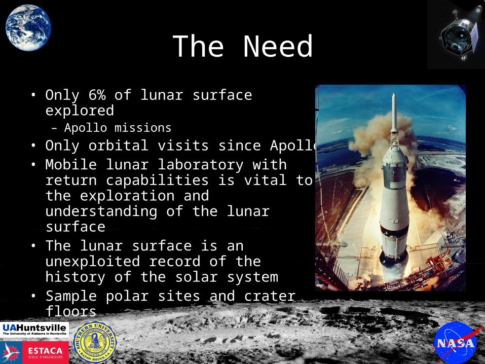
The Need
• Only 6% of lunar surface explored– Apollo missions
• Only orbital visits since Apollo• Mobile lunar laboratory with return
capabilities is vital to the exploration and understanding of the lunar surface
• The lunar surface is an unexploited record of the history of the solar system
• Sample polar sites and crater floors
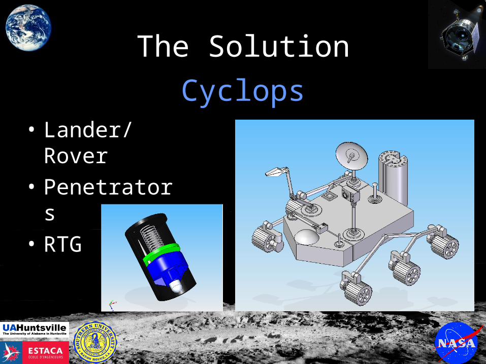
The Solution
• Lander/Rover
• Penetrators
• RTG
Cyclops
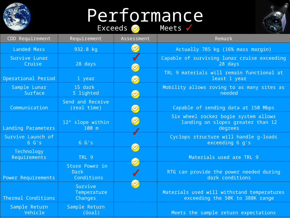
PerformanceCDD Requirement Requirement Assessment Remark
Landed Mass 932.8 kg Actually 785 kg (16% mass margin)
Survive Lunar Cruise 28 days Capable of surviving lunar cruise exceeding 28 days
Operational Period 1 year TRL 9 materials will remain functional at least 1 year
Sample Lunar Surface15 dark 5 lighted Mobility allows roving to as many sites as needed
CommunicationSend and Receive
(real time) Capable of sending data at 150 Mbps
Landing Parameters 12º slope within 100 mSix wheel rocker bogie system allows landing on slopes
greater than 12 degrees
Survive Launch of 6 G's 6 G's Cyclops structure will handle g-loads exceeding 6 g’s
TechnologyRequirements TRL 9 Materials used are TRL 9
Power Requirements Store Power in Dark
Conditions RTG can provide the power needed during dark conditions
Thermal ConditionsSurvive Temperature
ChangesMaterials used will withstand temperatures exceeding the
50K to 380K range
Sample Return Vehicle Sample Return (Goal) Meets the sample return expectations
MobileRoving/Real-Time
Mobility 6 wheel rocker bogie allows roving in real-time
Exceeds - Meets -
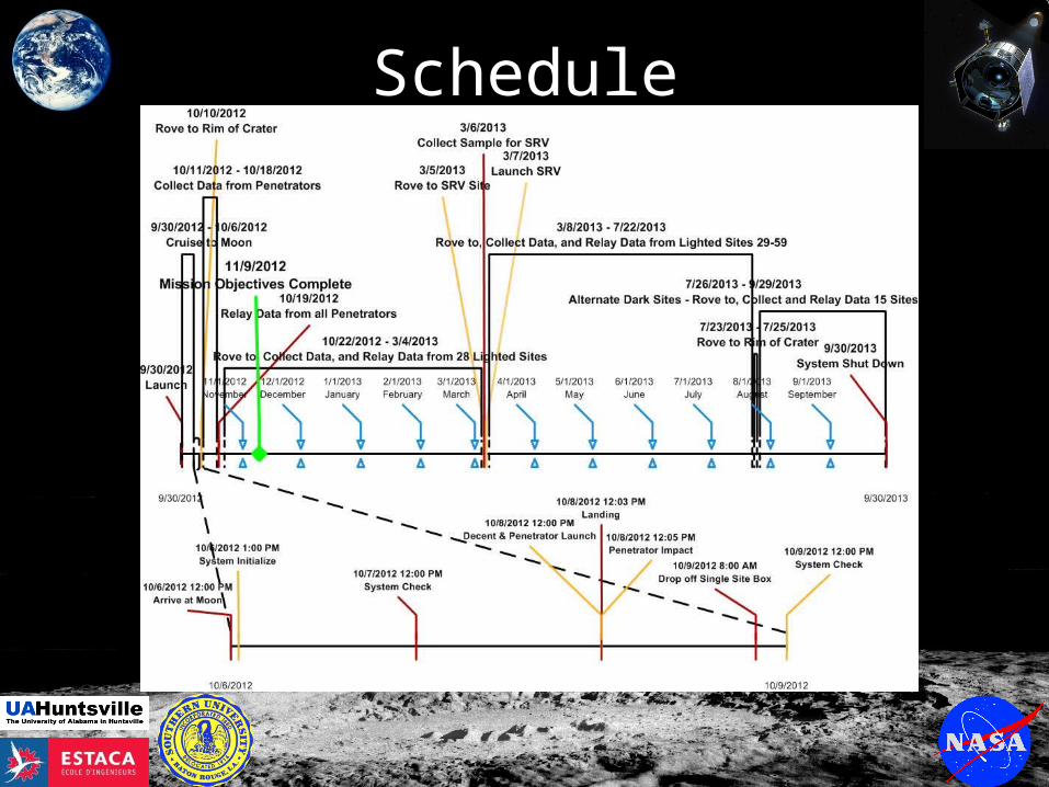
Schedule
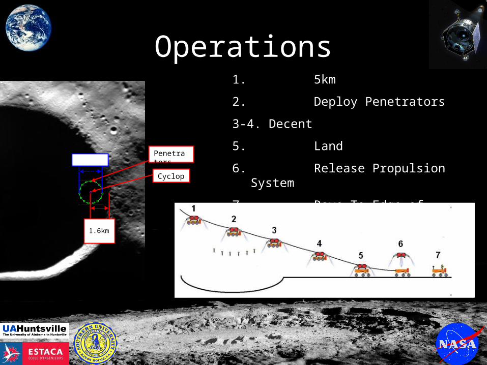
Operations
Cyclops
Penetrators 2.5km
1.6km
1. 5km
2. Deploy Penetrators
3-4. Decent
5. Land
6. Release Propulsion System
7. Rove To Edge of Crater
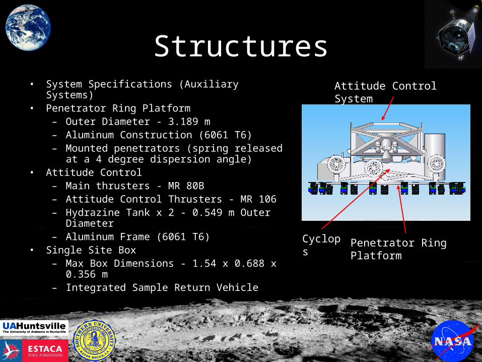
Structures• System Specifications (Auxiliary Systems)• Penetrator Ring Platform
– Outer Diameter - 3.189 m – Aluminum Construction (6061 T6)– Mounted penetrators (spring released at a 4
degree dispersion angle)• Attitude Control
– Main thrusters - MR 80B– Attitude Control Thrusters - MR 106– Hydrazine Tank x 2 - 0.549 m Outer Diameter– Aluminum Frame (6061 T6)
• Single Site Box– Max Box Dimensions - 1.54 x 0.688 x 0.356 m– Integrated Sample Return Vehicle
Penetrator Ring Platform
Attitude Control System
Cyclops
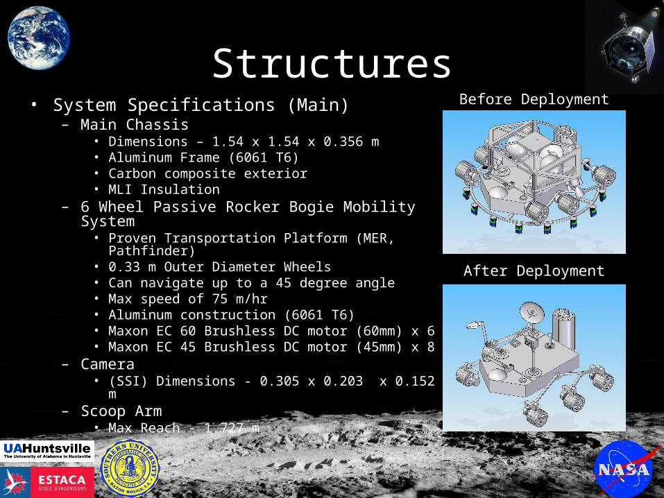
Structures• System Specifications (Main)
– Main Chassis• Dimensions – 1.54 x 1.54 x 0.356 m• Aluminum Frame (6061 T6)• Carbon composite exterior• MLI Insulation
– 6 Wheel Passive Rocker Bogie Mobility System• Proven Transportation Platform (MER, Pathfinder)• 0.33 m Outer Diameter Wheels• Can navigate up to a 45 degree angle• Max speed of 75 m/hr• Aluminum construction (6061 T6)• Maxon EC 60 Brushless DC motor (60mm) x 6• Maxon EC 45 Brushless DC motor (45mm) x 8
– Camera• (SSI) Dimensions - 0.305 x 0.203 x 0.152 m
– Scoop Arm• Max Reach - 1.727 m
Before Deployment
After Deployment
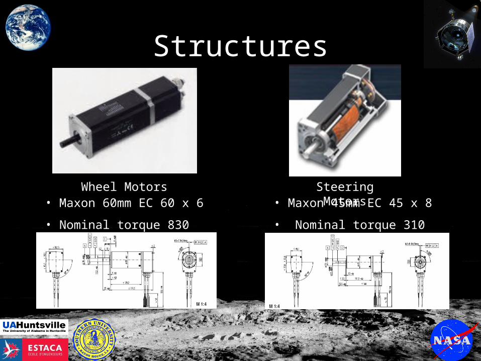
Structures
• Maxon 60mm EC 60 x 6
• Nominal torque 830 mNm
• Maxon 45mm EC 45 x 8
• Nominal torque 310 mNm
Wheel Motors Steering Motors
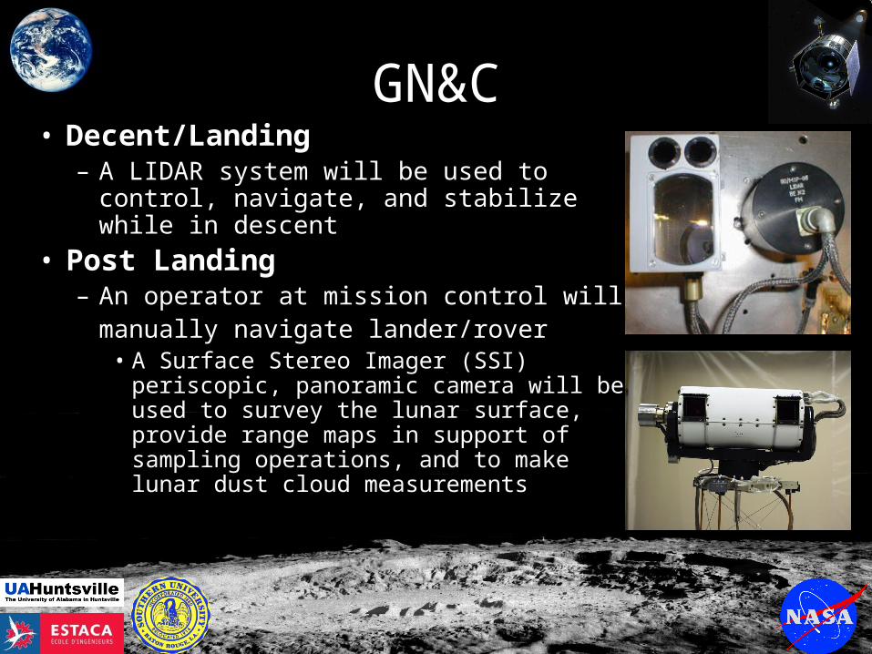
GN&C• Decent/Landing
– A LIDAR system will be used to control, navigate, and stabilize while in descent
• Post Landing – An operator at mission control will
manually navigate lander/rover• A Surface Stereo Imager (SSI)
periscopic, panoramic camera will be used to survey the lunar surface, provide range maps in support of sampling operations, and to make lunar dust cloud measurements
GN&C
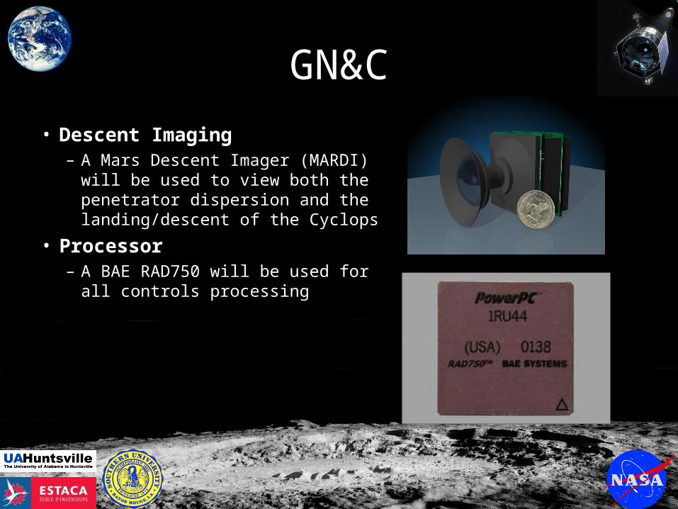
• Descent Imaging– A Mars Descent Imager (MARDI) will
be used to view both the penetrator dispersion and the landing/descent of the Cyclops
• Processor– A BAE RAD750 will be used for all
controls processing
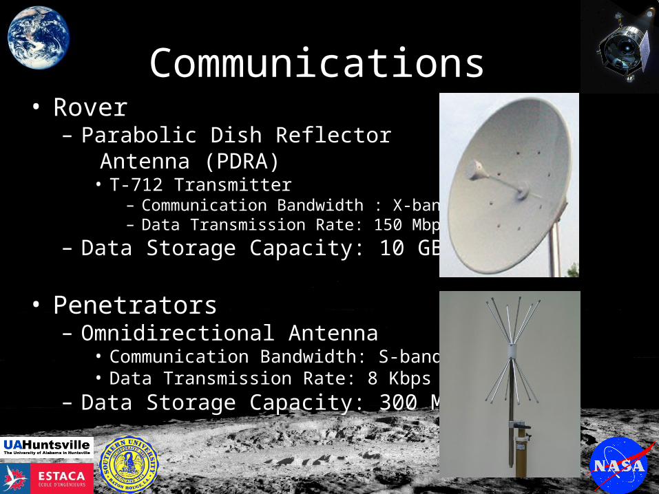
Communications • Rover
– Parabolic Dish Reflector Antenna (PDRA)
• T-712 Transmitter – Communication Bandwidth : X-band– Data Transmission Rate: 150 Mbps
– Data Storage Capacity: 10 GB
• Penetrators – Omnidirectional Antenna
• Communication Bandwidth: S-band • Data Transmission Rate: 8 Kbps
– Data Storage Capacity: 300 MB
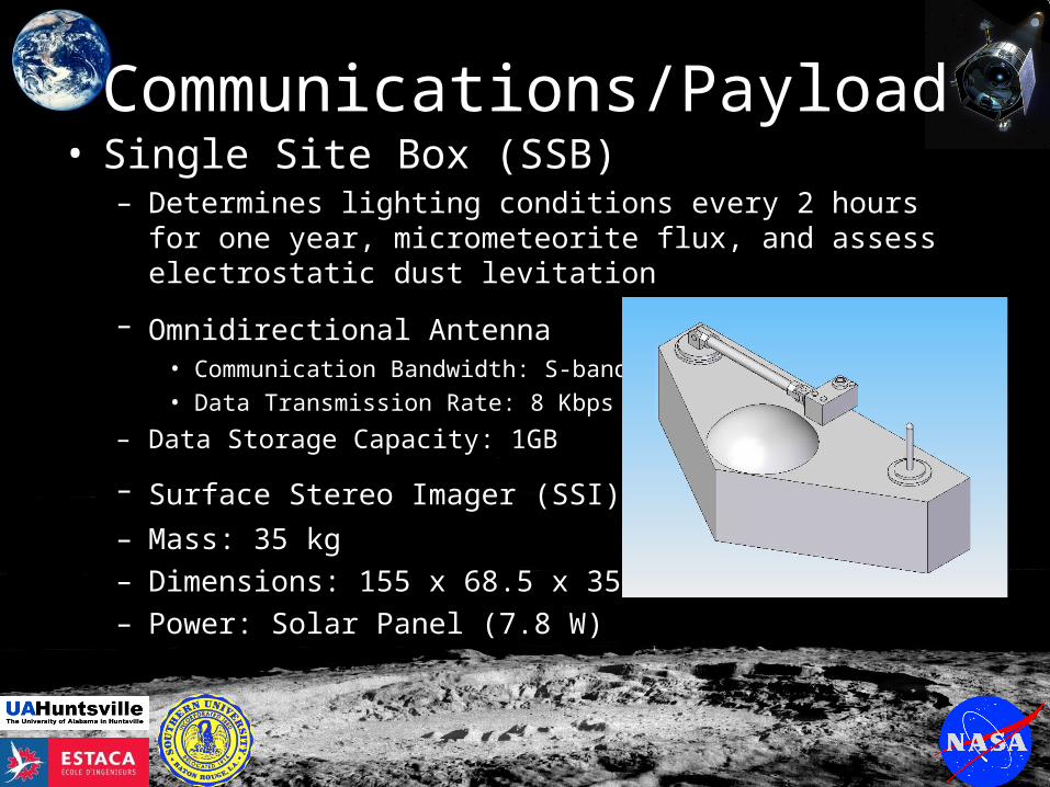
Communications/Payload• Single Site Box (SSB)
– Determines lighting conditions every 2 hours for one year, micrometeorite flux, and assess electrostatic dust levitation
– Omnidirectional Antenna • Communication Bandwidth: S-band • Data Transmission Rate: 8 Kbps
– Data Storage Capacity: 1GB
– Surface Stereo Imager (SSI) – Mass: 35 kg– Dimensions: 155 x 68.5 x 35.5 cm– Power: Solar Panel (7.8 W)
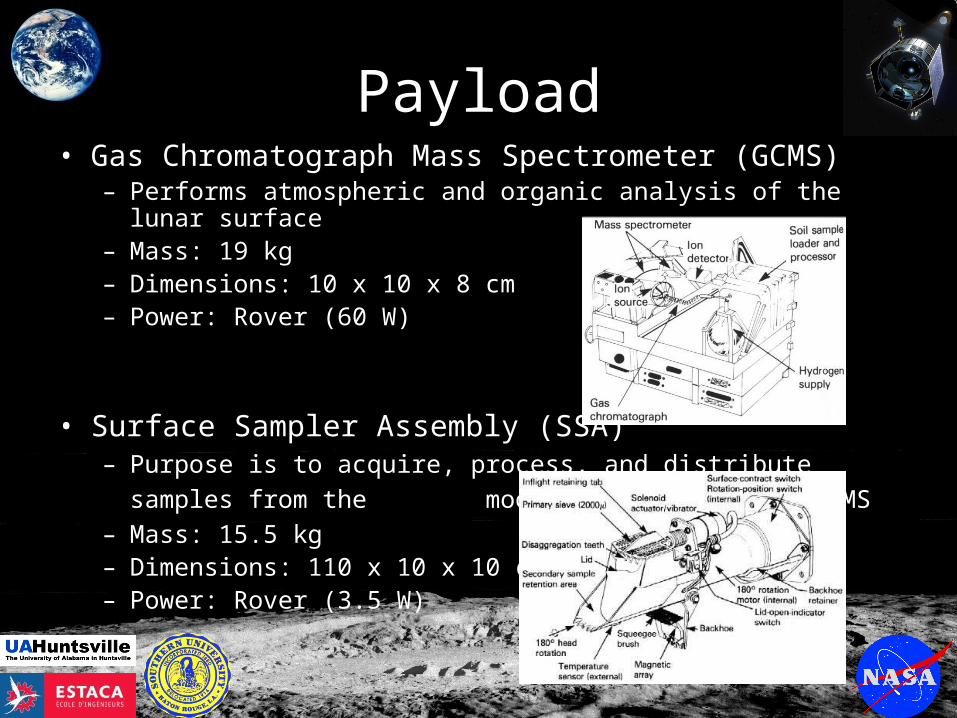
Payload• Gas Chromatograph Mass Spectrometer (GCMS)
– Performs atmospheric and organic analysis of the lunar surface – Mass: 19 kg– Dimensions: 10 x 10 x 8 cm– Power: Rover (60 W)
• Surface Sampler Assembly (SSA)– Purpose is to acquire, process, and distribute samples from the
moon’s surface to the GCMS – Mass: 15.5 kg– Dimensions: 110 x 10 x 10 cm– Power: Rover (3.5 W)
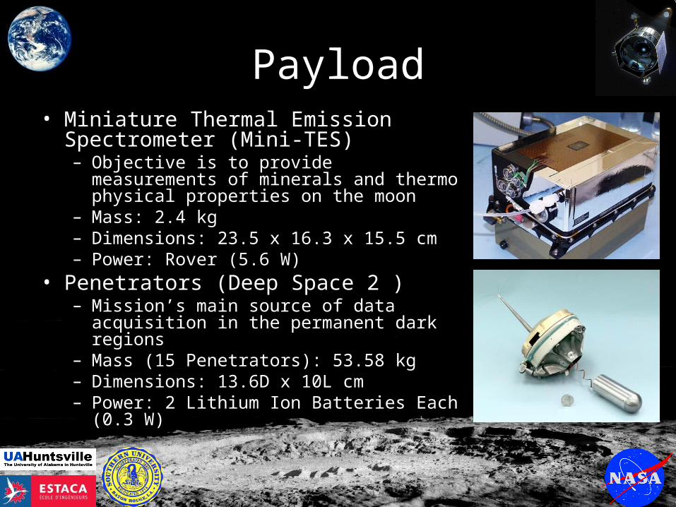
Payload• Miniature Thermal Emission
Spectrometer (Mini-TES) – Objective is to provide measurements of
minerals and thermo physical properties on the moon
– Mass: 2.4 kg– Dimensions: 23.5 x 16.3 x 15.5 cm– Power: Rover (5.6 W)
• Penetrators (Deep Space 2 )– Mission’s main source of data acquisition in
the permanent dark regions – Mass (15 Penetrators): 53.58 kg – Dimensions: 13.6D x 10L cm– Power: 2 Lithium Ion Batteries Each (0.3
W)

Power• RTG
– TRL 9– Constant power supply– Thermal output can be utilized for
thermal systems• Lithium-Ion Batteries
– Commercially available– Easily customizable– Rechargeable
• Solar Cell– Used for Single Site Box– Conventional– Increasingly efficient in well light
areas
POWER SUBSYSTEM
Type (solar, battery, RTG) Solar, Lithium-ion, RTG
Total mass 63.62 kg
Total power required 431.35 W
Number of solar arrays 1
Solar array mass/solar array 1.13 kg
Solar array area/solar array 0.12 square meter
Number of batteries 2
Battery mass/battery 3.25 kg
Number of RTGs 1
RTG Mass/RTG 56 kg
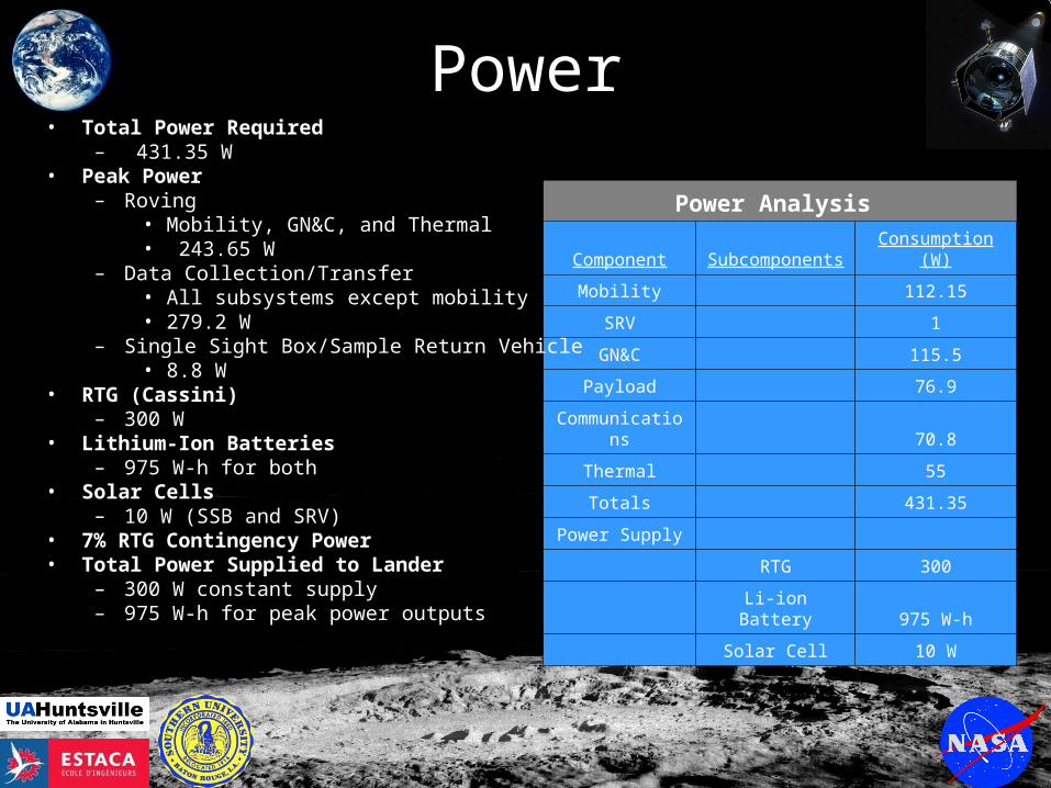
Power
Power Analysis
Component Subcomponents Consumption (W)
Mobility 112.15
SRV 1
GN&C 115.5
Payload 76.9
Communications 70.8
Thermal 55
Totals 431.35
Power Supply
RTG 300
Li-ion Battery 975 W-h
Solar Cell 10 W
• Total Power Required– 431.35 W
• Peak Power– Roving
• Mobility, GN&C, and Thermal• 243.65 W
– Data Collection/Transfer• All subsystems except mobility• 279.2 W
– Single Sight Box/Sample Return Vehicle• 8.8 W
• RTG (Cassini)– 300 W
• Lithium-Ion Batteries– 975 W-h for both
• Solar Cells– 10 W (SSB and SRV)
• 7% RTG Contingency Power• Total Power Supplied to Lander
– 300 W constant supply– 975 W-h for peak power outputs
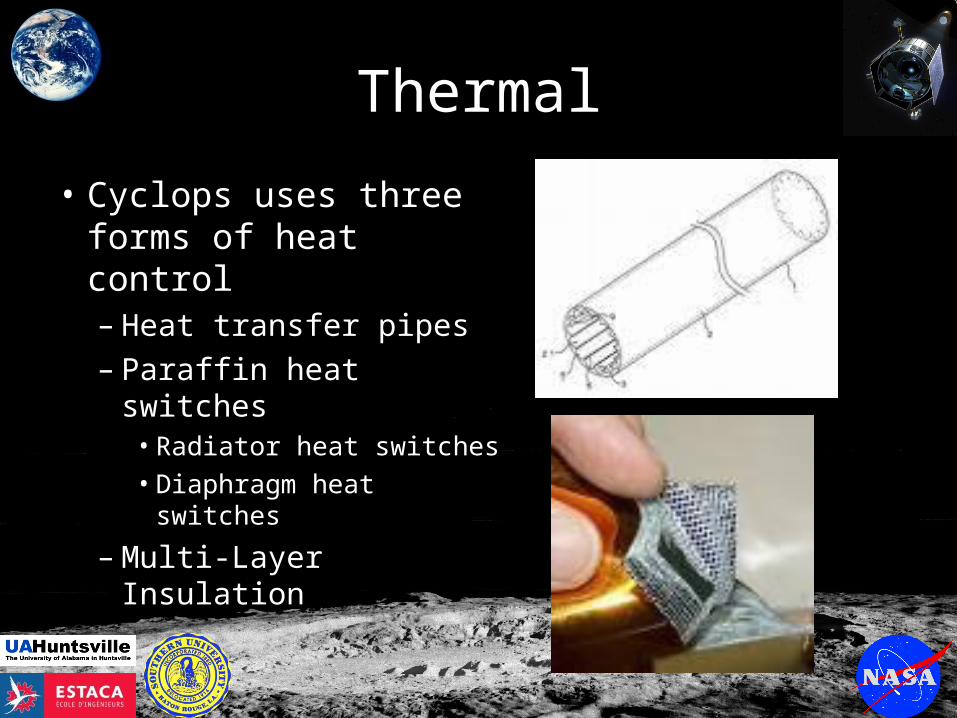
Thermal
• Cyclops uses three forms of heat control– Heat transfer pipes– Paraffin heat switches
• Radiator heat switches• Diaphragm heat
switches
– Multi-Layer Insulation
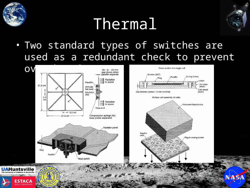
Thermal• Two standard types of switches are used as a
redundant check to prevent over heating
Thermal
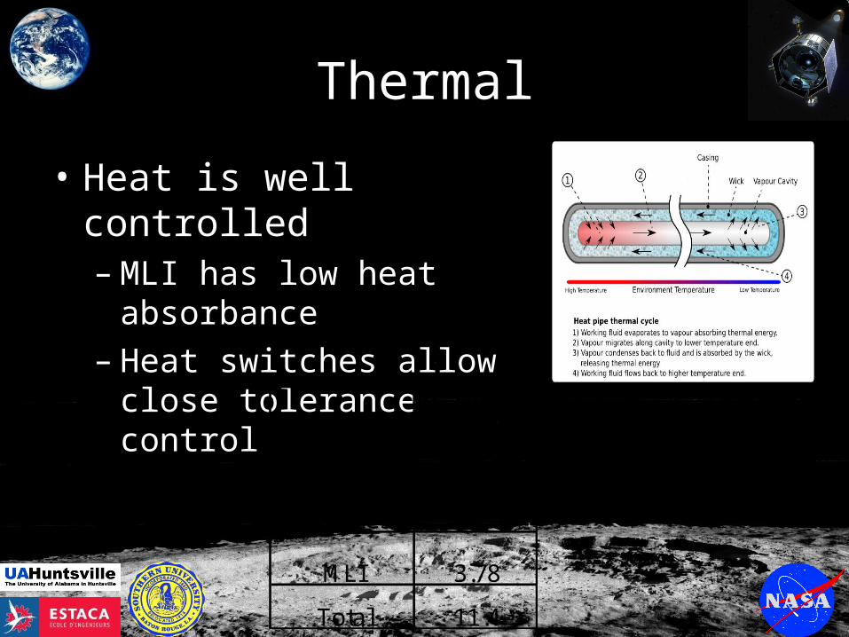
• Heat is well controlled– MLI has low heat
absorbance– Heat switches allow close
tolerance controlMass (kg)
Heat pipes 4.62
Heat Switches 3
MLI 3.78
Total 11.4
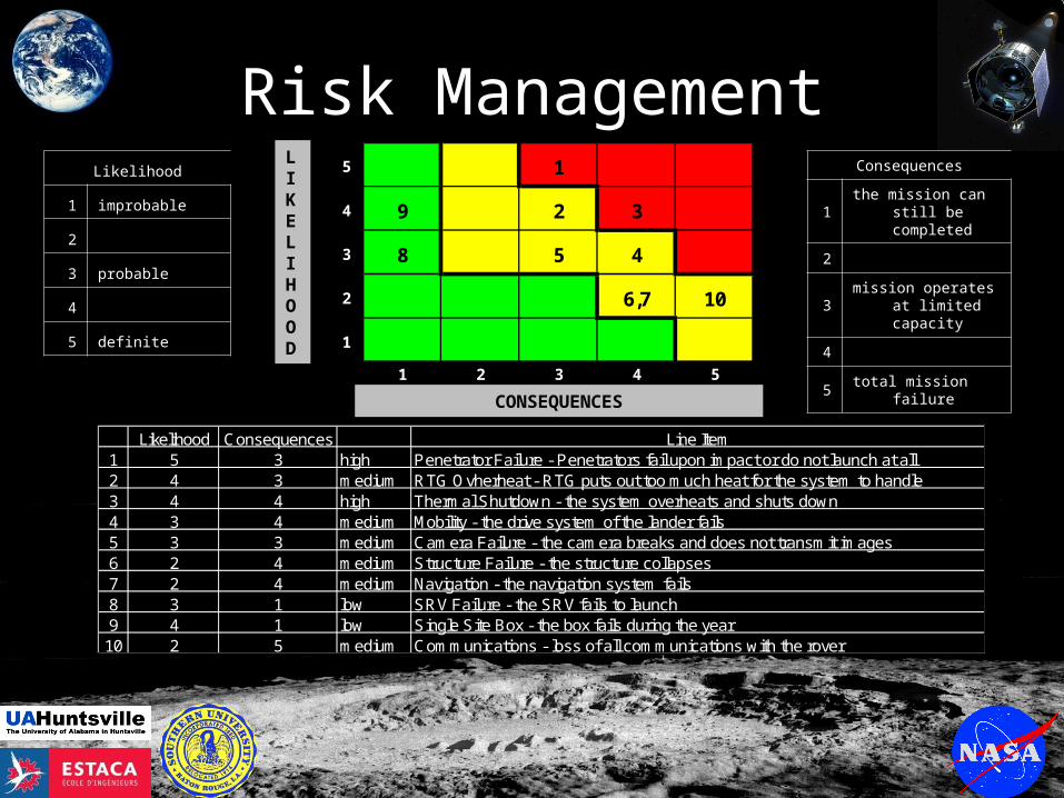
Risk Management5 1
4 9 2 3
3 8 5 4
2 6,7 10
1
1 2 3 4 5
LIKELIHOOD
CONSEQUENCES
L ikelihood C ons equences L ine Item1 5 3 high P enetrator F ailure - P enetrators fail upon impact or do not launch at all2 4 3 medium R TG O vherheat - R TG puts out too much heat for the s ys tem to handle3 4 4 high Thermal S hutdown - the s ys tem overheats and s huts down4 3 4 medium Mobility - the drive s ys tem of the lander fails5 3 3 medium C amera F ailure - the camera breaks and does not trans mit images6 2 4 medium S tructure F ailure - the s tructure collaps es7 2 4 medium Navigation - the navigation s ys tem fails8 3 1 low S R V F ailure - the S R V fails to launch9 4 1 low S ingle S ite B ox - the box fails during the year
10 2 5 medium C ommunications - los s of all communications with the rover
Likelihood
1 improbable
2
3 probable
4
5 definite
Consequences
1 the mission can still be completed
2
3 mission operates at limited capacity
4
5 total mission failure

Mass AllocationsSystem Mass (kg) Percent Mass
GN&C 23.5 3%
Payload 278 35.4%
Communications 20 2.5%
Thermal 11.4 1.5%
Power Supply 64 8.2%
Structures 173.1 22.1%
Mobility 215 27.4%
Total Mass 785 kg 100%
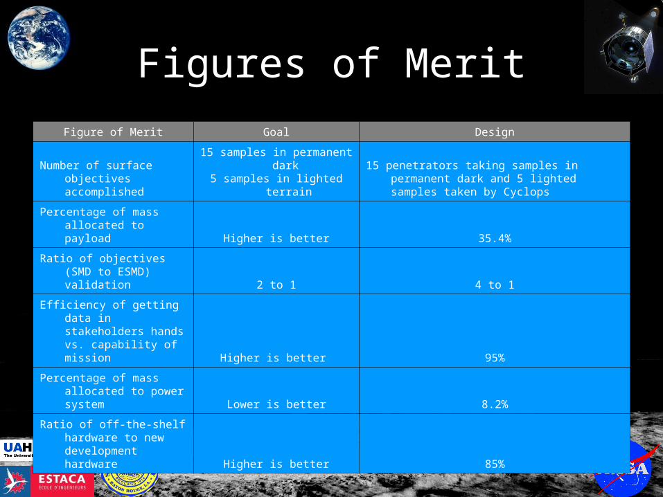
Figures of Merit
Figure of Merit Goal Design
Number of surface objectives accomplished
15 samples in permanent dark 5 samples in lighted terrain
15 penetrators taking samples in permanent dark and 5 lighted samples taken by Cyclops
Percentage of mass allocated to payload Higher is better 35.4%
Ratio of objectives (SMD to ESMD) validation 2 to 1 4 to 1
Efficiency of getting data in stakeholders hands vs. capability of mission Higher is better 95%
Percentage of mass allocated to power system Lower is better 8.2%
Ratio of off-the-shelf hardware to new development hardware Higher is better 85%
Conclusions
• “There’s no place this thing can’t go”
• If penetrators fail, remaining mission will not be compromised
• Reliable multi-faceted design
Questions