luminsight this guide introduces the luminsight cms web ... we… · real time controlling in view...
TRANSCRIPT

This guide introduces the LumInsight CMS Web Portal dashboard. Use this guide to set up Geozones, update and delete devices, manage alarms, manage group controllers, and troubleshoot your Geozones.
LumInsight
CMS Web
Portal User’s
Guide

Echelon, LumInsight, and the Echelon logo are trademarks of
Echelon Corporation that may be registered in the United
States and other countries.
Other brand and product names are trademarks or
registered trademarks of their respective holders.
Smart Transceivers, Neuron Chips, and other OEM Products
were not designed for use in equipment or systems, which
involve danger to human health or safety, or a risk of
property damage and Echelon assumes no responsibility or
liability for use of the Smart Transceivers or Neuron Chips in
such applications.
Parts manufactured by vendors other than Echelon and
referenced in this document have been described for
illustrative purposes only, and may not have been tested
by Echelon. It is the responsibility of the customer to
determine the suitability of these parts for each
application.
ECHELON MAKES AND YOU RECEIVE NO WARRANTIES OR
CONDITIONS, EXPRESS, IMPLIED, STATUTORY OR IN ANY
COMMUNICATION WITH YOU, AND ECHELON SPECIFICALLY
DISCLAIMS ANY IMPLIED WARRANTY OF MERCHANTABILITY
OR FITNESS FOR A PARTICULAR PURPOSE.
No part of this publication may be reproduced, stored in a
retrieval system, or transmitted, in any form or by any means,
electronic, mechanical, photocopying, recording, or
otherwise, without the prior written permission of Echelon
Corporation.
Printed in the United States of America.
Copyright © 2015 - 2017 Echelon Corporation.
Echelon Corporation
www.echelon.com

Welcome This document describes the features and operation of Echelon’s LumInsight Web Portal Tool.
Audience This manual shows you the dashboard of the LumInsight CMS Web Portal. Use this guide to set
up Geozones, update and delete devices, manage alarms, manage group controllers, manage
FPMs, and troubleshoot your Geozones.
Examples Throughout this PDF, screen shots will guide you through the process of using the LumInsight
Web Portal Tool.
Related Documentation The following manuals are available from the Echelon Web site (www.echelon.com) and provide
additional information for the LumInsight products.
Title
Part Number
Description
LumInsight CMS Installation Guide
078-0159-01C
This manual helps you install your LumInsight product.
LumInsight Provisioning Tool User’s Guide
078-1060-01D
This guide shows you how to use the provisioning tool to create projects, set up the segment controller page, configure TCP/IP, configure GPRS, set control groups, define and provision devices, create devices, create bulk devices, and commission your products.
LumInsight Web Portal Tool User’s Guide iii

Contacting Echelon To contact Echelon Support Center or access our Knowledge Base:
Phone: US Toll free 1-877-844-7444 | Int’l 1-408- 790-3037 |
email: [email protected] | Web: https://echelon.force.com/support
iv LumInsight Web Portal Tool User’s Guide

iv LumInsight Web Portal User Guide
Contents
About this Guide................................................................................................................... ii Introduction .............................................................................................................................................. ii How To Find Information .......................................................................................................................... ii How To Contact Echelon .......................................................................................................................... iv
Forgot Password ................................................................................................................................ 2
System Information .................................................................................................................................. 4 Geozones Wise Energy Usage ........................................................................................................... 4 Geozone Wise Faulty Devices Widget ............................................................................................... 6 Geozone Wise Device Status Widget ................................................................................................ 6 Geozones ........................................................................................................................................... 7
Profile ....................................................................................................................................................... 8 User Activity ............................................................................................................................................. 9
Geozones ................................................................................................................................................ 11 Create Geozone ............................................................................................................................... 11
Devices ................................................................................................................................................... 14 Update Device ................................................................................................................................. 15 Delete Device .................................................................................................................................. 20 Delete Segment Controller .............................................................................................................. 20 View Details of Device ..................................................................................................................... 20
Geopositioning ....................................................................................................................................... 23 Scene Definition ..................................................................................................................................... 25
View Devices with Scene ................................................................................................................. 26 Edit Scene Definition Configuration ................................................................................................ 26 Delete Confirm ................................................................................................................................ 26
Import Devices ....................................................................................................................................... 27 Download Template ........................................................................................................................ 28 Cancel Uploading ............................................................................................................................. 28 Remove File After Browse ............................................................................................................... 28
Export Devices ........................................................................................................................................ 29 Replace Devices ...................................................................................................................................... 30 Replace Segment Controller ................................................................................................................... 31
Select Geozone ................................................................................................................................ 36 View Full Screen .............................................................................................................................. 36 Filter Devices in Map ....................................................................................................................... 36 Real Time Controlling in View Devices ............................................................................................ 37 Read Device Information ................................................................................................................. 38
Segment Controller .................................................................................................................. 38 Motion Sensor .......................................................................................................................... 38

LumInsight Web Portal User Guide v
Segment Controller Contactor ................................................................................................ 39 Digital Sensor ........................................................................................................................... 39 CPD 3000 Lighting Controller ................................................................................................... 40 CLP 3000 Lighting Controller .................................................................................................... 40 CPD 3000 Light and CLP 3000 Light ......................................................................................... 41
Alarm Definition ..................................................................................................................................... 42 Create Alarm ................................................................................................................................... 43 Update an Alarm ............................................................................................................................. 46 Delete An Alarm .............................................................................................................................. 46 Enable/ Disable an Alarm ................................................................................................................ 47 Alarm Type ...................................................................................................................................... 48
Active Alarms .......................................................................................................................................... 49 Set Acknowledge An Active Alarm .................................................................................................. 49 View Acknowledge History .............................................................................................................. 49
Dimming Profile ...................................................................................................................................... 50 Create Dimming Profile ................................................................................................................... 51 Dimming Profile Scenes ................................................................................................................... 51 Segment Schedule ........................................................................................................................... 52 Update Dimming Profile .................................................................................................................. 52 Delete Dimming Profile ................................................................................................................... 53
Segment Schedule .................................................................................................................................. 53 Create Segment Schedule ............................................................................................................... 54 Apply Commission ........................................................................................................................... 56 Apply Uncommission ....................................................................................................................... 57 Update Segment Controller Schedule ............................................................................................. 57 Delete Segment Schedule ............................................................................................................... 58 Delete Scheduler from Calendar ..................................................................................................... 58
Group Controller .................................................................................................................................... 59 Group Lighting Controller ................................................................................................................ 60 Dimming Profiles ............................................................................................................................. 62 Bind Device ...................................................................................................................................... 62 Update ............................................................................................................................................. 63
Network Mode ....................................................................................................................................... 64 1. OnNet .......................................................................................................................................... 65 2. OffNet .......................................................................................................................................... 65 3. Maintenance ............................................................................................................................... 65
Poll Manager .......................................................................................................................................... 65 Log Manager ........................................................................................................................................... 67
Apply Binding to Motion Sensor...................................................................................................... 71 Apply Binding to Digital Sensor ....................................................................................................... 72
Users ....................................................................................................................................................... 74 Create User ...................................................................................................................................... 74 Role Configuration .......................................................................................................................... 75 Update User .................................................................................................................................... 76 Delete User ...................................................................................................................................... 77

vi LumInsight Web Portal User Guide
View User Activity ........................................................................................................................... 77 Geozone Lock .........................................................................................................................................77
Database Backup .................................................................................................................................... 79 Database Restore.......................................................................................................................................... 79
Query Status ........................................................................................................................................... 80 Test Devices ............................................................................................................................................ 81 Poll Statistics ........................................................................................................................................... 82 Log Statistics ........................................................................................................................................... 83 Segment Controller Dashboard .............................................................................................................. 85
Data History ............................................................................................................................................ 86 Operating Data ................................................................................................................................ 86 Failures ............................................................................................................................................ 86 Group Controller Scene ................................................................................................................... 87 Energy Data ..................................................................................................................................... 88
Export Energy Data ................................................................................................................................. 89 Device Lifetime ....................................................................................................................................... 91
Display the Device Lifetime Pie Chart for a Particular Geozone ......................................................91 Failure Analysis ....................................................................................................................................... 92
Display a Detailed Failure Report for a Particular Geozone ............................................................93 Failure Tracking ............................................................................................................................................. 93
Aggregated Number of Failures per Geozone ................................................................................ 93 Display Faulty Devices on a Map ..................................................................................................... 94
Cabinet Access History ........................................................................................................................... 95 Log Delivered History ............................................................................................................................. 95 Reset History .......................................................................................................................................... 95

1 LumInsight Web Portal User Guide
1. Login Page
This section familiarizes you with the usage of the LumInsight Web Portal.
Figure 1. Login Page
Figure 2. Invalid License Page
To access the LumInsight web portal, type the IP address in browser and
press Enter. It will open the LumInsight login page as shown in Figure 1.
This page allows you to log in to LumInsight . If the user has entered the valid UserName and Password then LumInsight will check for the LumInsight license. If license is valid then user will signin, otherwise it will open the error page as shown in Figure 2. Here you will be able to signin. If the license server is unreachable, after the signin we will send notification Email on license server.
If you tick the ‘remember me’ box, your user name and password will be
saved in a cookie on this computer. Next time you log on you will not need
to re-enter these details. If you delete the cookie or your browser is set to

Forgot Password
Follow the below steps for forgot password.
1. Click on Forgot Password link for reset password.
3. Enter new password and click on Save.
Figure 3. Forgot Password
Figure 4. Reset Password
LumInsight Web Portal User Guide 2
not accept cookies this function will not work. You can de-select the function
at any time by removing the tick from the box.
The Web interface of LumInsight is supported in IE8+ or above, Mozila
Firefox and Google Chrome
2. Enter User Name as shown in Figure 3. Click on Submit. You will receive
the mail of reset password via Email. Please check mail, we have sent
the mail for Reset Password. In the mail click on Reset Now as shown
in Figure 4. The link will expire in 2 hours.
3 LumInsight Web Portal User Guide
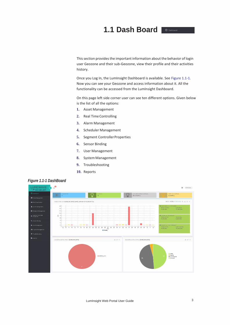
1.1 Dash Board
Figure 1.1-1 DashBoard
1. Asset Management
2. Real Time Controlling
3. Alarm Management
4. Scheduler Management
5. Segment Controller Properties
6. Sensor Binding
7. User Management
8. System Management
9. Troubleshooting
10. Reports
This section provides the important information about the behavior of login
user Geozone and their sub-Geozone, view their profile and their activities
history.
Once you Log In, the LumInsight Dashboard is available. See Figure 1.1-1.
Now you can see your Geozone and access information about it. All the
functionality can be accessed from the LumInsight Dashboard.
On this page left side corner user can see ten different options. Given below
is the list of all the options:

4 LumInsight Web Portal User Guide
DashBoard
Table 1.1-1 Dashboard Description
Blue Box Total number of Geozones
Green Box Total number of devices in Geozones
Grey Box Total number of devices un-configured in
Geozones
Yellow Box Total number of inactive devices in
Geozones
System
Information
Figure 1.1-2 System Information
Geozones Wise Energy Usage
Across the top of the Dashboard are four boxes. Table 1.1-1 describes each
of the boxes displayed under login user in brief.
A geozone is used to partition the hierarchy of the assets in the system. A
geozone can have multiple sub-geozones energy usage of Daily, Weekly and
Monthly. The following Figure 1.1-3, Figure 1.1-4 and Figure 1.1-5. Show
examples of each usage.
Click on icon, to access LumInsight system version information from your Dashboard as shown in Figure 1.1-2.

5 LumInsight Web Portal User Guide
System Information
Figure 1.1-3 Geozones Wise Energy Usage Daily
Figure 1.1-4 Geozones Wise Energy Usage Weekly
Figure 1.1-5 Geozones Wise Energy Usage Monthly
In addition to displaying the energy usage by day, week, or month, you can
also compare energy usage over time. In the figures, this is displayed in the
three green boxes on the right.
There are three colors in the energy graph which indicates the under
report energy - light red, normal report energy - light blue and over report
energy - light yellow.

6 LumInsight Web Portal User Guide
DashBoard
Table 1.1-2 describes each of the displayed under login user in brief.
Table 1.1-2 Geozones Wise Energy Usage Description
Today VS THIS DAY LAST Display the energy usage of today
and this day last week.
THIS WEEK VS LAST WEEK Display the energy usage of this
week and last week.
TODAY VS YESTERDAY Display the energy usage of today
and yesterday.
Geozone Wise Faulty Devices Widget
where you want to check for faulty devices. See Figure 1.1-6.
Figure 1.1-6 Geozone Wise Faulty Devices Widget
Geozone Wise Device Status Widget
The Dashboard includes a widget to display any faulty devices in your
Geozone, if they exist. Move your mouse across the pie and if there is a faulty
device. By clicking on icon, you can select the Geozone
This widget, also on the Dashboard, describes the number of devices and
their status under your Geozone login. Move your mouse across the pie and
popups will describe the number of active devices, inactive devices, and
unconfigured devices in the Geozone.
By clicking on icon, you will be able to select the Geozone to view. the
selected Geozone can have multiple sub Geozones status devices. See
Figure 1.1-7.

7 LumInsight Web Portal User Guide
System Information
Figure 1.1-7 Geozone Wise Device Status Widget
Geozones
Figure 1.1-8 Geozones
Figure 1.1-9 Devices of Specific Geozone
This widget will display the login user's devices and Geozone can have
multiple sub-geozones. See Figure 1.1-8.
By clicking on Geozone, it will display the devices and a Geozone can have
multiple sub Geozones as shown in Figure 1.1-9.

8 LumInsight Web Portal User Guide
DashBoard
Profile
Table 1.1-3 describes each of the icons displayed on the page in brief.
Table 1.1-3 Widget Icon Description
Zoom Used to Zoom In and Out
- Used to expand collapse
Refresh Used to refresh the widget
Figure 1.1-10 User Page
Table 1.1-4 describes each of the icons displayed on the page in brief.
Table 1.1-4 User Page Icon Description
Profile View the current user profile
User Activity View current user activities log
License
Information
To view the license information
Log Out To exit the LUMINSIGHT web page
Click on icon, to view current user profile, activities history, license
Information, and logout from system. See Figure 1.1-10.
By clicking on Profile, it will display the profile information, change password
and dashboard widget settings display as shown in Figure 1.1-11.

9 LumInsight Web Portal User Guide
User Activity
Figure 1.1-11 Profile Page
User Activity
the system. By default, you can see the last two day’s worth of activity
(module wise, as well as timing) and view other activities. The activity is
displayed for only the logged in user. See Figure 1.1-12.
To change password from profile page, enter your Old password, New
password and retype password. Click on Change, to change password as
shown in Figure 1.1-11.
To change widgets setting from profile page. Check box to display on
dashboard and uncheck to not display on dashboard. Click on Save.
User activity display only for login user. If you want to see other sub-user
activity, you can see it from User page under User Management Menu.
The User Activity page displays user actions performed on the whole system,
module-wise. It tracks activities and is useful to find behavior that changes

10 LumInsight Web Portal User Guide
DashBoard
Figure 1.1-12 User Activity Page
Table 1.1-5 describes each of the icons displayed on the page in brief.
Table 1.1-5 User Activity Page Icon Description
View More Displays the more activity
User Name Indicates user name
The User Activity page displays the user name and the gives you a button to
see more activity.

11 LumInsight Web Portal User Guide
Geozones
1.2 Asset Management
This section gives you an overview of Asset Management.
Figure 1.2-1 Geozones
Table 1.2.1 describes each of the icons displayed on the page in brief.
Table 1.2.1 Manage Geozones Page Icon Description
Create Geozone Allows to create new Geozone
View Area Allows to view existing Geozone
area
Update Geozone Allows to edit existing Geozone
Delete Allows to delete Geozone
Create Geozone
Click on Create Geozone icon, to create Geozone as shown in Figure 1.2-2.
This page allows to create Geozones, update Geozones, and delete and view
areas under your logged in Geozones and their sub Geozones . See
Figure 1.2-1.

12 LumInsight Web Portal User Guide
Asset Management
Figure 1.2-2 Create Geozone
Select Geozone Area.
Name: Enter name of Geozone.
Parent Geozone: Select parent Geozone.
NorthEast Latitude: NorthEast Latitude
NorthEast Longitude: NorthEast Longitude
SouthEast Latitude: SouthEast Latitude
SouthEast Longitude: SouthEast Longitude
Click on Save, to add your new Geozone.
GEOZONE TREE: By selecting the Geozone from the Geozone tree it will
display in the LumInsight system page. Changes at the Geozone tree will
change in the LumInsight system page. All changes here will reflect in
LumInsight.
Click on
shown in Figure 1.2-3.
icon, to choose the area for your Geozone as

13 LumInsight Web Portal User Guide
Geozones
Figure 1.2-3 Select Geozone Area
Table 1.2.2 describes each of the icons displayed on the page in brief.
Table 1.2.2 Select Geozone Area Icon Description
Zoom Allows to zoom In and Out of map
- Draw area of geozone
Edit Allows to update Geo position of
device
Search Allows to search from map
This is where you use LumInsight to draw the area that will include your
Geozone and click on Submit – this adds in NorthEast Latitude, NorthEast
Longitude, SouthWest Latitude, and SouthWest Longitude.

14 LumInsight Web Portal User Guide
Asset Management
Devices
Figure 1.2-4 Manage Devices
Table 1.2.3 describes each of the icons displayed on the page in brief.
Table 1.2.3 Manage Devices Icon Description
Geozone Tree This is your Geozone tree.
By selecting the geozone
from the geozone tree. It
will display in
LUMINSIGHT system
pages. By changing the
Geozone from the
Geozone tree. It will change
in LUMINSIGHT system
pages.
Update Allows to update existing
device
Delete Allows to delete device
LumInsight portal will support the devices type as CPD 3000 Lighting
Controller, CLP 3000 Lighting Controller, CPD 3000 Light, CLP 3000 Light,
Motion Sensor, CRD 3000 Street Light Bridge, Segment Control Contactor
and Digital Sensor. For more information of devices icon see Table 1.3.1
Devices Map Icons Description.
This page allows editing, deletion, and viewing of devices (Devices + Controller) in
this Geozone. Hierarchy Geozone devices information associated with the
login user will display. See Figure 1.2-4.

15 LumInsight Web Portal User Guide
Devices
Delete Segment
Controller
Allows to delete segment
controller and delete
segment controller with all
references
Note: If user has admin role
View Device
Details
Used to view device details
Update Device
Figure 1.2-5 Edit Device
Click on icon, to edit an existing device as shown in Figure 1.2-5.
If the device type is Segment Controller then there is additional field
“Polling”. There are two values for Active and Passive.
On the Device Information tab, you can enter the name of the device or
controller (a controller is also one type of a device). You can add the Geo
Location at this screen, as well. Click on the for
pictorial representation of a device. Then click on
in map as shown in Figure 1.2-6.
to add device

16 LumInsight Web Portal User Guide
Asset Management
Figure 1.2-6 Device on Map
Figure 1.2-7 Draw Device on Map
Figure 1.2-8. shows the identity of an OLC.
Latitude and Longitude automatically add when you draw device in map and
click on Submit.
Click on icon, to draw device on map as shown in Figure 1.2-7. Once the
device is there, click Save.
Your device is now part of your Geozone. Use the Next and
Previous tab, to move forward and backward through your devices. In these
screens, under Update Device, you can also find the identity of devices.

17 LumInsight Web Portal User Guide
Devices
Figure 1.2-8 Identity for OLC
Segment Controller: Select the segment controller.
Figure 1.2-9 Identity for Segment Controller
When you identify a Segment Controller, the following fields are mandatory.
HostName: Host name of controller, is required.
Controller Technology: Select from list, is also required.
All fields are mandatory.
Do not change the entries from those used in the Identify dialog. The Neuron
ID/Unique Address should match your Neuron ID.
Once the information is displayed, click Next. Now you can set the identity
for a Segment Controller. See Figure 1.2-9.
Once the information has been entered, select Device in category, and click
Next. Figure 1.2-10. to create the identity for a sensor (Traffic Occupancy
Sensor (Sensor).

18 LumInsight Web Portal User Guide
Asset Management
Figure 1.2-10 Identity for Sensor
Just like the Segment Controller screen, all fields here are mandatory.
Figure 1.2-11 Inventory for OLC
Fill out the fields of this screen.
Lamp Type: Select the lamp type. Baseline
Power: Enter the baseline power. Fixture
Model: Enter the fixture model.
Datasheet URL: Enter the datasheet URL.
Installed Date: Select the installed date.
Service Notes: Enter the service not.
Continue in Update Device area and select Device in the category and click
next. You will now enter Inventory information to support your devices. In
this example, the device is a lamp. See Figure 1.2-11.
Click on icon, to update the device. See Figure 1.2-4.

19 LumInsight Web Portal User Guide
Devices
Cabinet Type: Select the cabinet type.
Address: Enter the address.
Installed Date: Select the installed date.
Comment: Enter the comment.
Figure 1.2-12 Inventory for Segment Controller
Figure 1.2-13 Inventory for Sensor
Only one field is required for a sensor.
Installed Date: Select the installed date.
Service Notes: Enter the service notes.
Now click Segment Controller and click on Next. The next Figure 1.2-12.
shows the inventory for the Segment Controller.
Click on icon, to update your controller. Continuing on, the next
step is to inventory a sensor. See Figure 1.2-13.

20 LumInsight Web Portal User Guide
Asset Management
Delete Device
Figure 1.2-14 Delete Device
Delete Segment Controller
Figure 1.2-15 Delete Segment Controller with All References
View Details of Device
If you want to eliminate a device, you can delete it from manage device
page.
Click on icon, to delete a device. Opens a user confirmation dialog
box. Click on Yes, to delete device as shown in Figure 1.2-14.
To delete a segment controller, click on icon, to open the user
confirmation dialog box. You can delete all references to the controller with
this selection, if you are an admin. Click on Yes, to delete segment controller
with all references as shown in Figure 1.2-15.
User can delete segment controller with all references if the user has the
admin role.
Click on icon, to view details of device. This is only for view purpose as
shown in Figure 1.2-16., Figure 1.2-18 and Figure 1.2-19.

21 LumInsight Web Portal User Guide
Devices
Figure 1.2-16 View Details of Category Type - Device
Figure 1.2-17 More Information
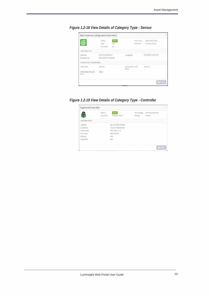
In addition to viewing the details of a device, you can use the same steps to
view details of a sensor or a controller. See Figure 1.2-18. and Figure 1.2-19.
By clicking on icon at the top of the screen, to view the more
information for your device as shown in Figure 1.2-17.
22 LumInsight Web Portal User Guide
Asset Management
Figure 1.2-18 View Details of Category Type - Sensor
Figure 1.2-19 View Details of Category Type - Controller

23 LumInsight Web Portal User Guide
Geopositioning
Figure 1.2-20 Update Device Location
icon, it will close sidebar.
Click on Save, to save devices position. See Figure 1.2-21.
Figure 1.2-21 Save Devices
This page displays devices and sub-Geozones of selected Geozones from
Geozone tree. User can change device location on map and to reset
positioning options. See Figure 1.2-20.
For more information of devices icon see Table 1.3.1 Devices Map Icons
Description.
Click on icon, to open sidebar and display Geozone tree in it, click on
any Geozone, display their devices with sub Geozones in Map. Again click on
Click on icon, to reset devices. See Figure 1.2-22.

24 LumInsight Web Portal User Guide
Asset Management
Figure 1.2-22 Reset Devices
Figure 1.2-23 Selected Area in Manage Geozone
Figure 1.2-24 Manage Geopositioning View Devices
You will not able to move the devices from the Geozone boundary.
By using icon, you will able to select area for single and multiple
devices to change Geoposition as shown in Figure 1.2-23.
Right click on “Segment Controller”, to view devices of selected segment
controller with their group controller as shown in Figure 1.2-24.

25 LumInsight Web Portal User Guide
Scene Definition
Scene
Definition
GEOZONE TREE: Selecting the Geozone from the Geozone tree will
display devices of that selected Geozone on the map. You will be able to
change location of devices.
Table 1.2.4 describes each of the icons displayed on the page in brief.
Table 1.2.4 Manage Geopositioning View Devices Icon Description
Device is in group.
Device is not in group.
Device is selected to view devices.
Figure 1.2-25 Scene Definition
Table 1.2.5 describes each of the icons displayed on the page in brief.
Table 1.2.5 Scene Definition Page Icon Description
Occupancy
Events
Indicates the scene is configured to
respond to occupancy events
View Devices with
Scene
Allows to view existing segment
controller scene definition
Edit Scene Allows to edit existing segment
controller scene definition
Delete Confirm Allows to delete segment controller
scene definition
This page allows to view, edit and delete scene definition as shown in
Figure 1.2-25.
26 LumInsight Web Portal User Guide
Asset Management
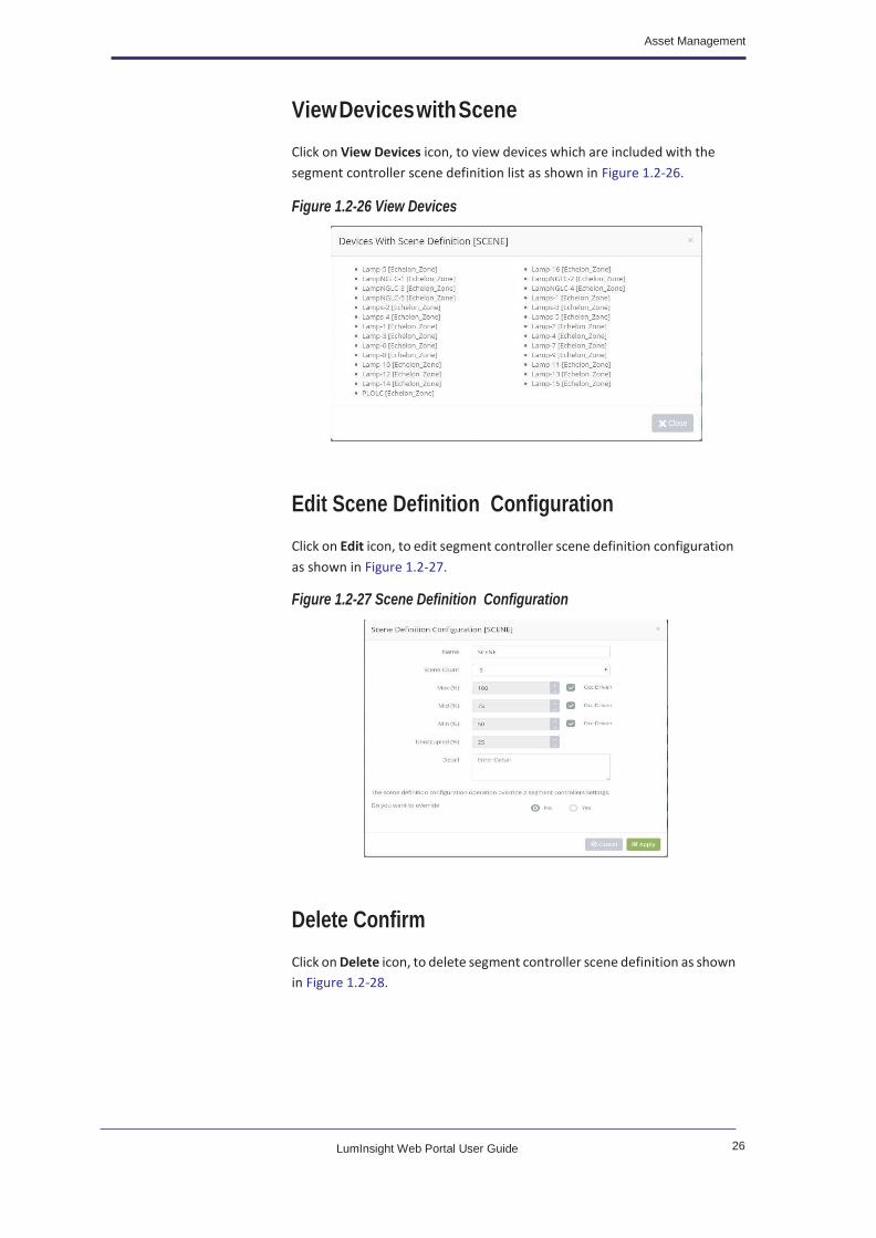
View Devices with Scene
Figure 1.2-26 View Devices
Edit Scene Definition Configuration
Figure 1.2-27 Scene Definition Configuration
Delete Confirm
Click on View Devices icon, to view devices which are included with the
segment controller scene definition list as shown in Figure 1.2-26.
Click on Edit icon, to edit segment controller scene definition configuration
as shown in Figure 1.2-27.
Click on Delete icon, to delete segment controller scene definition as shown
in Figure 1.2-28.

27 LumInsight Web Portal User Guide
Import Devices
Import Devices
Figure 1.2-28 Delete Confirm
Figure 1.2-29 Import Devices
Figure 1.2-30 Geo Positioning Confirm
Once you have browse file of devices and then uploaded. It will open the geo
positioning confirm dialog box. See Figure 1.2-30. There are options as Keep
the ERDP Geo positioning coordinates, Keep the CMS Geo positioning
coordinates and Apply Geo positioning coordinates to rest of all devices
same as above selected option.
On selection of Geo positioning, click on Yes, it will open the Controller
Polling Type dialog box. There are options active polling and passive polling
as shown in Figure 1.2-31.
This page allows to upload devices and controller from .erdp and upload
device location from csv file as well as download template (file format) for
upload devices location. See Figure 1.2-29.

28 LumInsight Web Portal User Guide
Asset Management
Figure 1.2-31 Controller Polling Type
Download Template
Click on Download, to download template.
Cancel Uploading
Automatically change status of next devices in data table (Status - Cancel).
Remove File After Browse
Template For Update Devices Location. (for update existing devices location)
Click on
See Figure 1.2-32.
icon, to download the template for devices upload.
Click on icon, to stop uploading from current upload device and next
devices not upload.
Click on icon, opens confirmation dialog box. Click on Yes, to
remove file after browse as shown in Figure 1.2-33.

29 LumInsight Web Portal User Guide
Export Devices
Export Devices
Figure 1.2-34 Export Devices
Figure 1.2-35 Select Attributes
Device is uploaded successfully, see “Imported/Updated” for devices.
“Imported/Scene Imported” for segment controller.” in status, if any error
then display error message in status and uploading cancel then display
“Cancel” in status.
Select Category to export the segment controller and device. Click on Next.
See Figure 1.2-35.
After selection of attributes, click on Export icon to export the csv file. Click
on Save, to save exported file as shown in Figure 1.2-36.
This page allows to export devices category wise (Segment Controller and
devices) as well as combine. See Figure 1.2-34.

30 LumInsight Web Portal User Guide
Asset Management
Replace
Devices
Figure 1.2-36 Save Exported File
Table 1.2.6 describes each of the icons displayed on the page in brief.
Table 1.2.6 Export Devices Icon Description
Select All Used to select all attributes
Invert Selection Used to invert selection of
attributes
Figure 1.2-37 Action for Replacing the Devices
This page allows to replace light or replace devices of the selected devices as
shown in Figure 1.2-37.
Select the devices from the replace page to replace light or devices as shown
in Figure 1.2-38. After applying the action, you will see the dialog box as
shown in Figure 1.2-38.

31 LumInsight Web Portal User Guide
Replace Segment Controller
Replace
Segment
Controller
Figure 1.2-39 Replace Segment Controller
Figure 1.2-40 Download ERDP
Figure 1.2-41 Browse Files
Enter New Unique Address/ Neuron Id of devices. Click OK to exit the dialog
box.
Click on icon, to download the ERDP file.
Click on icon, to browse file for replace segment controller
and its property as well as devices in it. File is accepted only .erdp.
This page allows exporting segment controller which is selected from
dropdown, it will export ERDP file containing devices, scenes, templates
information and other details. User can used ERDP file after resync using
Provisioning tool for replacing new segment controller as shown in
Figure 1.2-39
32 LumInsight Web Portal User Guide
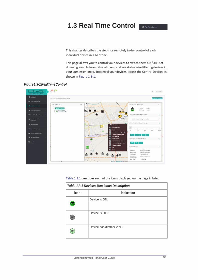
Figure 1.3-1 Real Time Control
1.3 Real Time Control
Table 1.3.1 describes each of the icons displayed on the page in brief.
Table 1.3.1 Devices Map Icons Description
Device is ON.
Device is OFF.
Device has dimmer 25%.
This chapter describes the steps for remotely taking control of each
individual device in a Geozone.
This page allows you to control your devices to switch them ON/OFF, set
dimming, read failure status of them, and see status wise filtering devices in
your LumInsight map. To control your devices, access the Control Devices as
shown in Figure 1.3-1.

33 LumInsight Web Portal User Guide
Table 1.3.1 Devices Map Icons Description
Device has dimmer 50%.
Device has dimmer 75%.
Device is Inactive.
Device is Unconfigured.
Device is unknown.
Device is in auto mode ON.
Device is in auto mode OFF.
Device is in auto mode with dimmer 25%.
Device is in auto mode with dimmer 50%.
Device is in auto mode with dimmer 75%.
Device is in auto mode with inactive status.
Device is in auto mode with unconfigured status.
Device is in auto mode with unknown status.
Segment controller is active with passive polling.
Segment controller is inactive with passive polling.

34 LumInsight Web Portal User Guide
Real Time Control
Table 1.3.1 Devices Map Icons Description
Segment controller is active with active polling.
Segment controller is inactive with active polling.
Sensor is configured.
Sensor is unconfigured.
Sensor is inactive.
Sensor is unknown.
Bridge is configured.
Bridge is inactive.
Bridge is unconfigured.
Bridge is unknown.
Direct control with dimmer 100.
Direct control with dimmer auto.
Direct control with dimmer 0.
Direct control is in auto mode with dimmer 100.

35 LumInsight Web Portal User Guide
Table 1.3.1 Devices Map Icons Description
Direct control is in auto mode with dimmer auto.
Direct control is in auto mode with dimmer 0.
CPD 3000 Lighting Controller is configured.
CPD 3000 Lighting Controller is inactive.
CPD 3000 Lighting Controller is unconfigured.
CPD 3000 Lighting Controller is unknown.
CLP 3000 Lighting Controller is configured.
CLP 3000 Lighting Controller is inactive.
CLP 3000 Lighting Controller is unconfigured.
CLP 3000 Lighting Controller is unknown.
Digital Sensor is configured.
Digital Sensor is inactive.
Digital Sensor is unconfigured.
Digital Sensor is unknown.
36 LumInsight Web Portal User Guide
Real Time Control
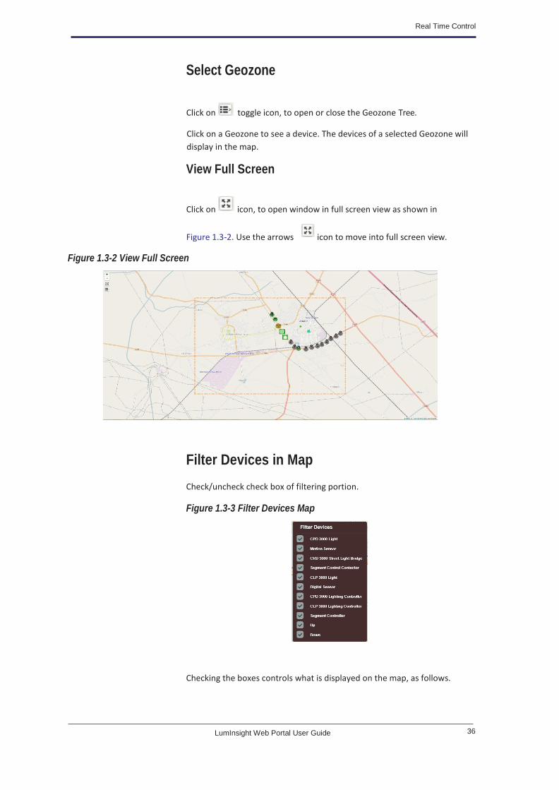
Select Geozone
View Full Screen
Figure 1.3-2 View Full Screen
Filter Devices in Map
Check/uncheck check box of filtering portion.
Figure 1.3-3 Filter Devices Map
Checking the boxes controls what is displayed on the map, as follows.
Click on toggle icon, to open or close the Geozone Tree.
Click on a Geozone to see a device. The devices of a selected Geozone will
display in the map.
Click on icon, to open window in full screen view as shown in
Figure 1.3-2. Use the arrows icon to move into full screen view.

37 LumInsight Web Portal User Guide
CPD 3000 Light: If unchecked, the ‘CPD 3000 Lights’ will not display on map.
CLP 3000 Light: If unchecked, the ‘CLP 3000 Lights’ will not display on map.
Digital Sensor: If unchecked, the ‘digital sensors’ will not display on map.
Up: If unchecked, any device that is ‘up’ will not be shown on map.
Down: If unchecked, any device that is ‘down’ will not be shown on map.
Real Time Controlling in View Devices
Figure 1.3-4 View Devices
Motion Sensor: If unchecked, the ‘motion sensor’ devices will not display on
map.
CRD 3000 Street Light Bridge: If unchecked, the ‘CRD 3000 Street Light
Bridges’ will not display on map.
Segment Controller Contactor: If unchecked, the ‘segment controller
contactors’ will not display on map.
CPD 3000 Lighting Controller: If unchecked, the ‘CPD 3000 lighting
controllers’ will not display on map.
CLP 3000 Lighting Controller: If unchecked, the ‘CLP 3000 lighting
controllers’ will not display on map.
Segment Controller: If unchecked, the ‘segment controllers’ will not display
on map.
Your map lets you view devices of a selected Geozone. Right click on
“Segment Controller”, to view devices of selected segment controller with
group as shown in Figure 1.3-4.

38 LumInsight Web Portal User Guide
Real Time Control
Table 1.3.2 describes each of the icons displayed on the page in brief.
Table 1.3.2 Real Time Controlling Map Icon Description
Device is in group.
Device is not in group.
Device is selected to view devices.
Read Device Information
Segment Controller
It is segment controller then display information as shown in Figure 1.3-5.
Figure 1.3-5 Set Dimming of All Devices of Segment Controller
Motion Sensor
It is sensor then display information as shown in Figure 1.3-6.
To read device information, double click in a device on the map or double
click on devices in a Geozone Tree. Open the right sidebar to display
information.
Dimming feature is applied only those devices which are supported dimming
function.
Set dimming of all devices by segment controller (required segment
controller is active.)

39 LumInsight Web Portal User Guide
Figure 1.3-6 Sensor Information
Motion Sensor is not supports dimmer functionality.
Segment Controller Contactor
Figure 1.3-7 Segment Controller Contactor Information
Digital Sensor
Figure 1.3-8. shows the digital sensor information.
Click on icon, to refresh device information (request to get data from
segment controller).
Set dimming of device by clicking on ON, OFF or AUTO (required device is
active). It will set the dimming value of group controller 1 in segment
controller as shown in Figure 1.3-7.

40 LumInsight Web Portal User Guide
Real Time Control
Figure 1.3-8 Digital Sensor
CPD 3000 Lighting Controller
Figure 1.3-9. shows the CPD 3000 lighting controller information.
Figure 1.3-9 CPD 3000 Lighting Controller
CLP 3000 Lighting Controller
Figure 1.3-10. shows the CLP 3000 lighting controller information.

41 LumInsight Web Portal User Guide
Figure 1.3-10 CLP 3000 Lighting Controller
CPD 3000 Light and CLP 3000 Light
Figure 1.3-11 Read Device Information
This is used to read device information, failure status, set dimming,
configured devices parameter (Device need to consider as active). If double
click on device, it displays device information as shown in Figure 1.3-11.

42 LumInsight Web Portal User Guide
Alarm
Definition
1.4 Alarm Management
This section gives you an overview of Alarm Management.
Figure 1.4-1 Manage Alarms
Table 1.4.1 describes each of the icons displayed on the page in brief.
Table 1.4.1 Alarm Icon Description
Indicates the alarm is enable as well as disable alarm by
clicking on it
Indicates the alarm is disable as well as enable alarm by
clicking on it
Display the failure alarm information
View the acknowledged history
View the Email Subscriber of Alarm
This page allows to view, create, edit, delete, enable and disable alarm for
the devices. Manage such alarms when failures and other data are collected
from devices. See Figure 1.4-1.

43 LumInsight Web Portal User Guide
Alarm Definition
Update the alarm
Delete Alarm
Create Alarm
This page allows to create a new alarm. See Figure 1.4-2.
Figure 1.4-2 Alarm Information
Name: Name of Geozone
Geozone: Select Geozone to create alarm
Geozone and Alarm type selection is required.
Click on Next, go to next wizard.
This screen display as per alarm type.
The process to create an alarm is generic. Most of the parameters are similar
from one type of alarm to the other. Thus, the process is described below
and the specific parameters for each type of alarms.
Click on icon, to create alarm.
Alarm Type: Select type of alarm to create (Each type of alarm is described
below).

44 LumInsight Web Portal User Guide
Alarm Management
Figure 1.4-3 Failure - Device Alarm : Failure Ratio In A Geozone
Figure 1.4-4 Failure - Device Alarm : Multiple Failures On Multiple Devices
Figure 1.4-5 Device Alarm : Single Alarm on Multiple Devices

45 LumInsight Web Portal User Guide
Alarm Definition
Figure 1.4-6 Failure - Device Alarm : Lost [Offline] Ratio In Geozone
Figure 1.4-7 Failure - Controller Alarm : Cabinet Alarm
Figure 1.4-8 Email
This page allows the user to select more than one other user to send email.
Fill all fields on failure wizard. Then Click on Next, you will see the Email
wizard as shown in Figure 1.4-8.
Click on icon, to select user for send email as shown in Figure 1.4-9.

46 LumInsight Web Portal User Guide
Alarm Management
Figure 1.4-9 Select User for Email
Fill in the parameters for the alarm as shown in Figure 1.4-8.
Click on Save, to add alarm.
Update an Alarm
This page allows to update an alarm.
Figure 1.4-10 Update an Alarm
Click on Update icon, to update the alarm.
Delete An Alarm
Figure 1.4-11 Delete an Alarm
Click on icon, to update the parameters of the selected alarm as shown in Figure 1.4-10.
Click on icon, to delete an alarm. View Confirmation dialog box. Click on
Delete to confirm. See Figure 1.4-11.
Click on icon, to view failures of created alarm. See Figure 1.4-12.

47 LumInsight Web Portal User Guide
Alarm Definition
Figure 1.4-12 Failure of Alarm
Figure 1.4-14 Acknowledged History
Enable/ Disable an Alarm
Alarm is enabled as well as disabled by clicking on it.
Alarm is disabled as well as enabled alarm by clicking on it.
Alarm will be triggered, only if the alarm is enabled.
Click on icon, to view list of email address of user to send mail while
alarm generates. See Figure 1.4-13.
Click on icon, to view acknowledged history as shown in Figure 1.4-14.

48 LumInsight Web Portal User Guide
Alarm Management
Alarm Type
Table below describes each type of alarm for a device and its parameters:
Cabinet alarm Alarm is triggered if segment
controller cabinet open and
triggered event detect by CMS.
Segment Controllers name.
Lost [OFFLINE] ratio in Geozone Alarm is triggered if system
detects that the percentage of
devices with inactive state in the
selected geozone.
Lost Devices Ratio (%):
percentage of inactive Devices is
reached which the alarm is
triggered.
Device alarm: failure
ratio in a group
Alarm is triggered if system
detects that the percentage of
devices with a failure (user defined
list of failures) in the selected
Geozone .
Critical failure ratio (%):
percentage of faulty Devices is
reached which the alarm is
triggered.
Failures: type of failures
considered to trigger this alarm.
Device alarm: multiple failures on
multiple devices
Alarm is triggered if system
detects that any of the devices in a
geozone and its sub-geozone has
a failure (user-defined failures).
Failures: type of failures
considered to trigger this alarm.
Equipment: devices to be
considered in this alarm.
Device alarm: single alarm on
multiple devices
Alarm is triggered if system
detects that the number of devices
with a failure (user-defined list of
failures) is above a user-defined
threshold in a Geozone and its
Sub-Geozones.
Failure number: threshold
(number of faulty devices) above
which the alarm is triggered.
Failures: type of failures
considered to trigger this alarm.
Equipment: devices to be
considered in this alarm.

49 LumInsight Web Portal User Guide
Active Alarms
Active Alarms
Display all active alarms of login user Geozone. See Figure 1.4-15.
Figure 1.4-15 Manage Active Alarms
Set Acknowledge an Active Alarm
This page allows to set acknowledge an active alarm.
Enter a comment in the entry field and click on Save.
Figure 1.4-16 Set Acknowledge an Active Alarm
View Acknowledge History
Click on icon, to set acknowledge for an active alarm. See Figure 1.4-16.
Click on icon, to view acknowledge history as shown in Figure 1.4-17.
This page allows display of the active alarms that have been triggered by the
system. Operators can acknowledged them from here. Alarm conditions are
configured using the “Manage Alarm Definition”.

50 LumInsight Web Portal User Guide
Dimming
Profile
1.5 Schedule Management
This section gives you an overview of Schedule Management.
Figure 1.5-1 Dimming Profile
Table 1.5.1 describes each of the icons displayed on the page in brief.
Table 1.5.1 Dimming Profile Icon Description
Create Dimming
Profile
Allows creation of the
dimming profile
Dimming Profile
Scenes
Display the chart of scene
vs time
Segment
Schedule with
Dimming Profile
Allows view of segment
schedule which contains
selected dimming profile
Update Allows update of dimming
profile
Delete Allows to delete dimming
profile
Update Dimming
Profile
Allows update dimming of
profile
Manage Dimming
Profiles
Allows to redirect on
manage dimming profiles
page
This page allows you to create, update and delete dimming profiles as shown in
Figure 1.5-1.

51 LumInsight Web Portal User Guide
Dimming Profile
Create Dimming Profile
Figure 1.5-2 Create Dimming Profile
Table 1.5.2 describes each of the icons displayed on the page in brief.
Table 1.5.2 Create Controller Icon Description
Save Dimming
Profile
Allows save of dimming
profile
Manage
Dimming Profiles
Allows to redirect on
manage dimming profiles
page
Add Allows to add scene in type,
time and scene
Type: Select Scheduler type
Time: Select time to display
the scene on time
Scene: Select Dimming
scene for max, min, mid and
off
Dimming Profile Scenes
Click on Create Dimming Profile icon, to create new dimming profile. See
Figure 1.5-2.
Click on icon, to view dimming scenes vs time chart as shown in
Figure 1.5-3.

52 LumInsight Web Portal User Guide
Scheduler Management
Segment Schedule
Figure 1.5-4 Segment Schedule
Update Dimming Profile
Figure 1.5-5 Update Dimming Profile
Click on icon, to view segment schedule list as shown in Figure 1.5-4.
Click on icon, to update the existing dimming profile as shown in
Figure 1.5-5.

53 LumInsight Web Portal User Guide
Segment Schedule
Table 1.5.3 describes each of the icons displayed on the page in brief.
Table 1.5.3 Update Dimming Profile Icon Description
Update Dimming
Profile
Allows to update dimming
profile
Manage
Dimming Profiles
Allows to redirect on
manage dimming profiles
page
Add Allows to add scene in type,
time and scene
Type: Select Scheduler type
Time: Select time to display
the scene on time
Scene: Select Dimming
scene for max, min, mid and
off
Edit Dimming
Profile Scene
Allows to edit dimming
profile scene
Delete Dimming
Scene
Allows to delete dimming
profile scene
Delete Dimming Profile
Figure 1.5-6 Delete Dimming Profile
Click on Yes, to delete the selected dimming profile.
Segment
Schedule
Click on icon, to delete selected dimming profile from the manage
dimming profile list page as shown in Figure 1.5-6.
This page allows to create segment schedule, update, delete, Commission
and Uncommission as shown in Figure 1.5-7.

54 LumInsight Web Portal User Guide
Scheduler Management
Figure 1.5-7 Segment Schedule
Table 1.5.4 describes each of the icons displayed on the page in brief.
Table 1.5.4 Segment Schedule Icon Description
Create Segment Schedule Allows to create segment
schedule
UnCommission Segment
Schedule
Shows the segment
schedule is not commission
in segment controller
Commission Segment
Schedule
Shows the segment
schedule is commission in
segment controller
Apply Commission
Segment Schedule
Allows to apply commission
segment schedule in
segment controller
Apply UnCommission
Segment Schedule
Allows to apply
uncommission segment
schedule in segment
controller
Update Allows to update segment
schedule
Delete Allows to delete segment
schedule
Create Segment Schedule
Click on Create Segment Schedule icon, to set the schedule for segment for
the selected group as shown in Figure 1.5-8.

55 LumInsight Web Portal User Guide
Segment Schedule
Figure 1.5-8 Create Segment Schedule
Figure 1.5-9 Select Group Controller
Click on Select icon, to select group controllers for segment schedule.
Figure 1.5-10 Daily Schedule
Enter and to
select the group controllers to create segment schedule as shown in
Figure 1.5-9.
Also you will able to set the segment schedule daily and exception as shown
in Figure 1.5-10 and Figure 1.5-11.
Click on days, you will see the daily schedule select dialog box as shown in
Figure 1.5-10.

56 LumInsight Web Portal User Guide
Scheduler Management
Please select schedule and click on Select.
Click on Save, to save the segment controller schedule.
Figure 1.5-11 Exception Schedule Definition
By clicking on any day from the scheduler page, it will pop up the daily
schedule definition as shown in Figure 1.5-12. Check the check box, to
schedule for Rest of the week.
Figure 1.5-12 Daily Schedule Definition - Sunday
Apply Commission
Figure 1.5-13 Apply Commission
Segment schedule commission on segment controllers.
By selecting on the month days, you will set the schedule for the exception
schedule as shown in Figure 1.5-11.
Click on Apply Commission icon, to apply commission schedule as shown in
Figure 1.5-13.

57 LumInsight Web Portal User Guide
Segment Schedule
Apply Uncommission
Figure 1.5-14 Apply Uncommission
Segment schedule Uncommission from segment controllers.
Update Segment Controller Schedule
Figure 1.5-15 Update Segment Controller Schedule
Click on Apply Uncommission icon, to apply uncommission schedule as
shown in Figure 1.5-14.
Click on icon, to update created segment controller schedule as shown
in Figure 1.5-15.
Click on any day
the update page. See Figure 1.5-16.
from

58 LumInsight Web Portal User Guide
Scheduler Management
Figure 1.5-16 Update Daily Schedule
Figure 1.5-17 Exception Schedule Definition
Delete Segment Schedule
Figure 1.5-18 Delete Segment Schedule
Click on Yes, to confirm the delete segment schedule.
Delete Scheduler from Calendar
By selecting on the month days, you will set the schedule for the exception
schedule as shown in Figure 1.5-17.
Click on icon, to update schedule for the group controller.
Click on icon, to delete segment schedule as shown in Figure 1.5-18.
By right clicking on any date of calendar and click on
as shown in Figure 1.5-19.
to delete schedule

59 LumInsight Web Portal User Guide
Group Controller
Table 1.5.5 describes each of the icons displayed on the page in brief.
Table 1.5.5 Manage Group Controller Icon Description
Group Lighting
Controller
Allows to view and configured the
group lighting controller
View Dimming
Profile
Allows to view dimming profiles done
on group controller
Bind Devices Allows to view bind devices
Update Allows to update group controller
name
This page allows to group lighting controller which includes 16 group controllers , dimming profiles and update. See Figure 1.5-20.

60 LumInsight Web Portal User Guide
Scheduler Management
Cancel Used to exit the dialog box
Refresh Display the latest information of
segment controller group
Group Lighting Controller
Group Lighting Controller Configuration Options:
Control State
Scheduled Exception
Time Override
Level Override
Temporary Scene
Figure 1.5-21 Control State
In the Scheduled Exception, set the scheduled date, time and exception
Figure 1.5-21.
Click on icon, to set the group lighting controller as shown in
duration time, override scene and click on
scheduled exception as shown in Figure 1.5-22.
icon, to set the

61 LumInsight Web Portal User Guide
Group Controller
Figure 1.5-22 Scheduled Exception
In the Time Override, set override duration time, override scene and click on
icon, to set the time override as shown in Figure 1.5-23.
In the Level Override, set the Control level and override duration time in
minutes shown in Figure 1.5-24.

62 LumInsight Web Portal User Guide
Scheduler Management
In the Temporary Scene, set the temporary scene as shown in Figure 1.5-25.
Figure 1.5-25 Temporary Scene
Dimming Profiles
Figure 1.5-26 Dimming Profiles
Bind Device
Click on icon, to view dimming profiles list for segment group controller
as shown in Figure 1.5-26.
Click on icon, to update the group controller name as shown in
Figure 1.5-27.

63 LumInsight Web Portal User Guide
Group Controller
Figure 1.5-27 Bind Device
Update
Figure 1.5-28 Update Group Name
Click on Update, to update the group controller schedule.
Click on icon, to update the group controller name as shown in Figure 1.5-28.

64 LumInsight Web Portal User Guide
1.6 Segment Controller Properties
This section gives you an overview of the Segment controller properties.
Network Mode Figure 1.6-1 shows the network management mode page.
Figure 1.6-1 Network Mode
Table 1.6.1 describes each of the icons displayed on the page in brief.
Table 1.6.1 Network Management Mode Icon Description
Configuration Mode Allows to apply
configuration mode
- Indicates the inactive
segment controller
Click on icon, to apply the configuration network mode as shown in
Figure 1.6-2.
Select when network configuration changes are propagated to segment
controller. There are three options available in Network Management
Mode.

65 LumInsight Web Portal User Guide
Poll Manager
1. OnNet
2. OffNet
3. Maintenance
Poll Manager This is used for settings segment controller configuration parameter.
Figure 1.6-3 Polling Manager
Table 1.6.2 describes each of the icons displayed on the page in brief.
Table 1.6.2 Polling Manager Icon Description
Operation Data Allows to apply operation
data configuration
Fault Data Allows to apply fault data
configuration
- Indicates the inactive
segment controller
Changes are sent immediately to the segment controller on the network.
Select OnNet if you are installing an engineered network, or if you are
designing and installing an ad-hoc network at the same time.
Changes are stored in the network database and then sent to the segment
controller on the network when you place the SmartServer OnNet. Select
OffNet if you are designing an engineered network.
Same as OnNet except that the SmartServer does not send out heartbeat
and polling messages. This increases the available bandwidth by freeing up
the consumption from checking data point heartbeats, sending poll
requests, and receiving poll message responses.

66 LumInsight Web Portal User Guide
Segment Controller Properties
Figure 1.6-5 General Mode Operation Data Configuration
Figure 1.6-6 Advance Mode Operation Data Configuration
Figure 1.6-7 General Mode Fault Data Configuration
Click on Operation Data icon, to apply operation data configuration as
shown in Figure 1.6-5. Selection of General mode, it will set the value for
data resolution as High, Mid, Min and Low.
Selection of Advance mode, set the value for data resolution manually as
shown in Figure 1.6-6.
Click on Fault Data icon, to apply operation data configuration as shown in
Figure 1.6-7 and Figure 1.6-8.

67 LumInsight Web Portal User Guide
Log Manager
Figure 1.6-8 Advance Mode Fault Data Configuration
Log Manager This is used for settings configuration parameters of the log.
Figure 1.6-9 Log Manager
Table 1.6.3 describes each of the icons displayed on the page in brief.
Table 1.6.3 Log Manager Icon Description
Operation Data Allows to apply operation
data configuration, displays
the number of operation log
received and indicates the
log manages is disabled or
enabled.
Fault Data Allows to apply fault data
configuration, displays the
number of fault log
received and indicates the
log manages is disabled or
enabled.
Dashboard Data Allows to apply dashboard
data configuration, displays
the number of dashboard
log received and indicates
the log manages is
disabled or enabled.

68 LumInsight Web Portal User Guide
Segment Controller Properties
Table 1.6.3 Log Manager Icon Description
Reporting Health Error Displays the report of
selected days if the
selected days will not
receive the data log for
operation data, fault data
and dashboard data then it
will indicates reporting
heath with error
Reporting Health Warning Displays the report of
selected days if the
selected days will received
the data log for operation
data, fault data or
dashboard data then it will
indicate reporting heath
with warning
Reporting Health OK Displays the report of
selected days if the
selected days received the
data log for operation
data, fault data and
dashboard data then it will
indicates reporting heath
with OK
- Indicates the inactive
segment controller
- Used to test web binder
and log manager working
properly or not
- Used to test web binder
and log manager working
properly
- Used to test web binder
and log manager not
working properly
Click on Operation Data icon, to apply operation data configuration as
shown in Figure 1.6-10.

69 LumInsight Web Portal User Guide
Log Manager
Figure 1.6-11 Fault Data Configuration
Figure 1.6-12 Dashboard Data Configuration
Click on Fault Data icon, to apply operation data configuration as shown in
Figure 1.6-11.
Click on Dashboard Data icon, to apply operation data configuration as
shown in Figure 1.6-12.

70 LumInsight Web Portal User Guide
1.7 Sensor Binding
This section gives you an overview of sensor binding.
Figure 1.7-1 Sensor Binding
This page allows binding devices with sensors. See Figure 1.7-1.
Table 1.7.1 describes each of the icons displayed on the page in brief.
Table 1.7.1 Binding Devices with Sensor Icon Description
View Geozones
Tree
Allows to expand Geozones tree to
bind devices with sensor
Bind Device Indicates device is bind
UnBind Device Indicates device is unbind
Bind Device with
number of
sensors bounded
Indicates device is bind with the 11
sensors
Apply Binding Allows to apply binding for selected
devices (or group of devices)
By right click on selected motion sensor or digital sensor, you will be able to
bind devices as shown in Figure 1.7-2.

71 LumInsight Web Portal User Guide
Figure 1.7-2 Bind Devices
Apply Binding to Motion Sensor
Figure 1.7-3 Apply Binding
This is used to view bound sensor list and bind and unbind devices and also
set hold time of sensor.
Click on icon, to apply binding by selecting the sensor for devices
as shown in Figure 1.7-3. You will be able to set the Hold Time.
After clicking on Apply icon, the checked devices are bind and unchecked
devices are unbind.

72 LumInsight Web Portal User Guide
Sensor Binding
Table 1.7.2 describes each of the icons displayed on the page in brief.
Table 1.7.2 Apply Binding Page Icon Description
No Indication the device is not bound
Yes Indication the device is bound
Yes - Bound with Indication the device is bound with
selected sensor as well as another
sensor
One device can bind with maximum
11 sensor
- Appears when the 11 sensors are
already bound with the device
- Hover on chain icon, it will display the
list of other sensors which are bound
with the device.
Apply Binding to Digital Sensor
If group of lights for CPD-3000 Lighting Controller or CLP-3000 Lighting
Controller is “TreatAsSame” then binding/unbinding of any one also bind/
unbind all others of the same group.
This is used to view bound digital sensor list and bind and unbind devices and
also set hold time of digital sensor.
Click on icon, to apply binding by selecting the digital sensor for
devices as shown in Figure 1.7-3. You will be able to set the hold time.

73 LumInsight Web Portal User Guide
Figure 1.7-4 Apply Binding
Figure 1.7-5 Configure Digital Sensor
If group of lights for CPD-3000 Lighting Controller or CLP-3000 Lighting
Controller is “TreatAsSame” then binding/unbinding of any one also binds/
unbinds others of same group.
By clicking icon, you will be able to set or change properties of digital
sensors. See Figure 1.7-5. You will make changes to the selected digital
sensor Type.

74 LumInsight Web Portal User Guide
1.8 User Management
Users
This section gives you an overview of User Management.
Figure 1.8-1 Users
Table 1.8.1 describes each of the icons displayed on the page in brief.
Table 1.8.1 Manage Users Page Icon Description
Create User Allows to create the user
Update Allows to edit in user profile
Delete Allows to delete user
User Activity Allows to view user activities log
Create User
See Figure 1.8-2. and Figure 1.8-3.
Click on the Create User icon, to add user. Fill in all the entry fields displayed
on the wizard.
Click on next tab, (you will be able to see User
Information, next is User Credential, and if you are in User Credential then
move on Role Configuration) and previous is reverse of it.
With this page, create, edit, delete and view Users and user’s activities of
login into user geozone and their sub-geozones. See Figure 1.8-1.

75 LumInsight Web Portal User Guide
Users
Figure 1.8-2 User Information
Figure 1.8-3 User Credential
Role Configuration
Figure 1.8-4 Role Configuration
This wizard is used to assign role to user (when user login, display module as
per the selection of role assign). See Figure 1.8-4.

76 LumInsight Web Portal User Guide
User Management
Update User
Figure 1.8-5 User Information
Figure 1.8-6 User Credential
After adding the user, if you want to make changes then click on the edit user
profile. You will see the edit page as shown in Figure 1.8-5.
User Information tab, you cannot make changes in geozones. See
Figure 1.8-5.
User Credential tab, you cannot make changes in user name. See
Figure 1.8-6
Check and uncheck the check box for selection of module to update the role
of configuration. Then, click on Update, to update the role of configuration.
See Figure 1.8-7.
77 LumInsight Web Portal User Guide
Geozone Lock
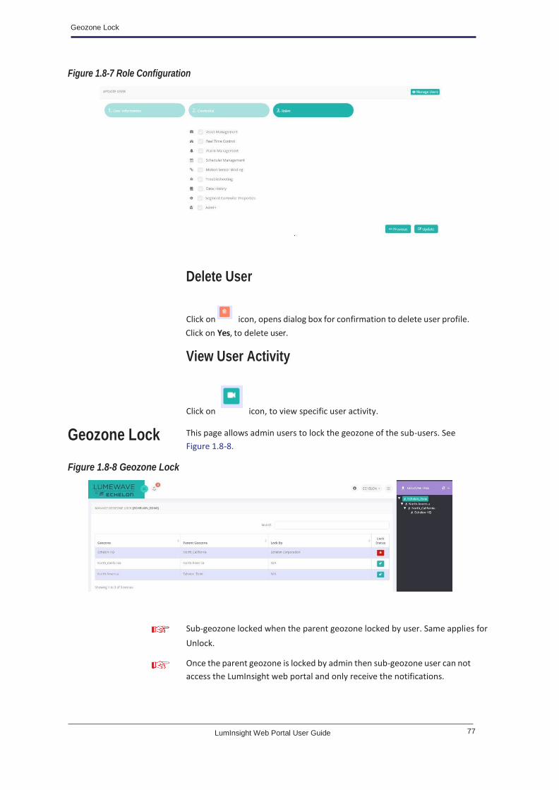
Figure 1.8-7 Role Configuration
Delete User
View User Activity
Geozone Lock
Figure 1.8-8 Geozone Lock
Click on icon, opens dialog box for confirmation to delete user profile.
Click on Yes, to delete user.
Click on icon, to view specific user activity.
Sub-geozone locked when the parent geozone locked by user. Same applies for
Unlock.
Once the parent geozone is locked by admin then sub-geozone user can not
access the LumInsight web portal and only receive the notifications.
This page allows admin users to lock the geozone of the sub-users. See
Figure 1.8-8.

78 LumInsight Web Portal User Guide
User Management
Table 1.8.1 describes each of the icons displayed on the page in brief.
Table 1.8.2 Lock Geozone Page Icon Description
Lock Allows to unlock the geozone
Unlock Allows to lock the geozone
Figure 1.8-9 Confirm Lock
Click on unlock icon, opens dialog box for confirmation to lock geozone. Click on Yes, to unlock geozone. See Figure 1.8-10.
Figure 1.8-10 Confirm Unlock
Click on lock icon, opens dialog box for confirmation to lock geozone. Click
on Yes, to lock geozone. See Figure 1.8-9.

79 LumInsight Web Portal User Guide
1.9 System Management
This section gives you an overview of the System Management.
Database
Backup
Figure 1.9-1 System Management - Database Backup
Table 1.9.1 describes each of the icons displayed on the page in brief.
Backup Allows to backup current database
Database
Restore
Figure 1.9-2 System Management - Database Restore
Table 1.9.2 describes each of the icons displayed on the page in brief.
Restore Allows to restore current or newer
version of database
This page allows to locate your database backup in your local network
system. See Figure 1.9-1. Also you have to provide the path to locate your
database backup.
This page allows to restore database from your local network system. See
Figure 1.9-2. Also you have to provide the path of database restore file.

80 LumInsight Web Portal User Guide
System Management
Database restore successfully only if the given database (input .backup file)
has version equal or greater than the current version of database.
Before the Database restore, your current database backup file has been
provided by CMS. It is located at the same path of Restore File Location.

80 LumInsight Web Portal User Guide
Query Status
1.10 Troubleshooting
This section gives you an overview of Troubleshooting.
Figure 1.10-1 Query Status
Table 1.10.1 describes each of the icons displayed on the page in brief.
Table 1.10.1 Troubleshooting Icon Description
Query Status Allows query status of all devices of selected controller
(sequentially)
If in sequence any device fail to query status,
then it stops process of checking devices.
Status of
Individual Device
Allows the query of status of individual device
Clicking on Query Status icon, you be will able to check selected devices
as shown in Figure 1.10-2. Also query status message display in
Query Status column.
This enables a view of the list of device status and query status on
a segment controller as shown in Figure 1.10-1.

81 LumInsight Web Portal User Guide
Test Devices
Figure 1.10-2 Status Message
Test Devices This page allows a view of the list of devices status as shown in Figure 1.10-3.
Figure 1.10-3 Test Devices
Table 1.10.2 describes each of the icons displayed on the page in brief.
Table 1.10.2 Test Devices Icon Description
Check Status Allows to check status of all devices of selected controller
(sequentially)
If in sequence any device fail to check status,
then stop process of check devices from fail
device and not check status of other devices.
Status of
Individual Device
Allows to check status of individual device
Clicking on Check Status icon, you will able to check selected devices or
device status as shown Figure 1.10-4. Check status message display in Action
Status column.

82 LumInsight Web Portal User Guide
Troubleshooting
Poll Statistics
Figure 1.10-5 Poll Statistics
Table 1.10.3 describes each of the icons displayed on the page in brief.
Table 1.10.3 Poll Statistics Icon Description
Poll Statistics View poll statics information of segment controller
Poll Trigger View poll trigger information of segment controller
- Indicates the inactive segment controller
Close Close to exit the Poll Statistics and Poll Trigger information dialog
box
Click on icon, it will display the poll statistics information for the
segment controller as shown in Figure 1.10-6.
This page is used to view poll statistics information and poll trigger
information as shown in Figure 1.10-5.

83 LumInsight Web Portal User Guide
Log Statistics
Log Statistics
Figure 1.10-7 Poll Trigger
Click on icon, it will display the poll trigger information segment
controller as shown in Figure 1.10-7.
This page is used to view operation statistic, fault statistic and dashboard
statistic information as shown in Figure 1.10-8.

84 LumInsight Web Portal User Guide
Troubleshooting
Figure 1.10-8 Log Statistics
Table 1.10.4 describes each of the icons displayed on the page in brief.
Table 1.10.4 Log Statistics Icon Description
Operation Statistics View the operation data information
Fault Statistics View the fault data configuration
Dashboard Statistics View the dashboard data configuration
- Indicates the inactive segment controller
Figure 1.10-9 Operation Statistics
Figure 1.10-10 Fault Statistics
Click on icon, it will display the operation data information as shown in
Figure 1.10-9.
Click on icon, it will display the fault data information as shown in
Figure 1.10-10.

85 LumInsight Web Portal User Guide
Segment Controller Dashboard
Figure 1.10-11 Dashboard Statistics
Segment
Controller
Dashboard
Figure 1.10-13 System Operating Values
Click on icon, it will display the dashboard data information as shown in
Figure 1.10-11.
Click on Segment Controller Dashboard, it will display the segment
controller dashboard information as shown in Figure 1.10-12.

86 LumInsight Web Portal User Guide
Data History
1.11 Reports
Operating Data
Figure 1.11-1 Operating Data History
Figure 1.11-2 Operating Data
Failures
Operating Data: Data history of Power, Voltage, Energy, Cycle Count, Level,
Rcv Time Outs, Power Factor, Temperature and RunTime. See Figure 1.11-2.
Select the data to display in the list of failure data for the selected segment
controller as shown in Figure 1.11-3.
This page allows the display of historical data on operations, failures and the
group controller scene. It is collected from any segment controller for a
particular date interval.

87 LumInsight Web Portal User Guide
Data History
Figure 1.11-3 Failure Data History
Figure 1.11-4 In Failures
Group Controller Scene
Figure 1.11-5 Group Controller Scene
In Failures: Data history of Low Power, High Power, Low Supply Voltage, High
Supply Voltage, High Temperature, Low PF, Relay Failed, Failed Start, Lamp
Failed and Status. See Figure 1.11-4.
Select the group controller scene, to display the scene of selected segment
controller as shown in Figure 1.11-5.

88 LumInsight Web Portal User Guide
Reports
Energy Data
Figure 1.11-6 OLC's Active Energy
Figure 1.11-7 Energy Data
Figure 1.11-8 Metered Active Energy
Select the energy data, it will display the selected segment controller of
selected date range as shown in Figure 1.11-6.
Energy Data: Energy data display for OLC's Active Energy, Metered Active
Energy, Metered Apparent Energy, Metered Reactive Energy as shown in
Figure 1.11-7.
Figure 1.11-8. shows the Metered Active energy for the selected segment
controller of selected date range.
Figure 1.11-9. shows the Metered Apparent energy for the selected segment
controller of selected date range.

89 LumInsight Web Portal User Guide
Export Energy Data
Figure 1.11-9 Metered Apparent Energy
Figure 1.11-10 Metered Reactive Energy
Export Energy
Data
Figure 1.11-10. shows the Metered Reactive energy for the selected segment
controller of selected date range.
If the user has selected geozone then it contains Geozone Metered Energy
Data Sum, Unmetered Energy Data Sum, OLC Energy Data Sum and
Individually OLC Data Sum of all devices under geozone hierarchy.
If the user has selected segment controller then it contains Geozone
Metered Energy Data Sum, Unmetered Energy Data Sum, OLC Energy Data
Sum and Individually OLC Data Sum of all devices under segment controller.
If the user has selected device then it contains OLC Energy Data Sum and
Date wise OLC Data Sum of selected device.
This page allows to export energy data based on selected geozone, segment
controller and device. See Figure 1.11-11., Figure 1.11-12. and
Figure 1.11-13.

90 LumInsight Web Portal User Guide
Reports
Figure 1.11-11 Export Energy Data for Geozone

91 LumInsight Web Portal User Guide
Device Lifetime
Device Lifetime
Click on Export icon, it opens the dialog box as shown in Figure 1.11-14.
Figure 1.11-14 Export
Click on Export to CSV icon, to export the csv files as shown in Figure 1.11-15.
Figure 1.11-15 Export to CSV
Display the Device Lifetime Pie Chart for a
Particular Geozone
Click on icon, to display the device lifetime (e.g. lamp lifetime) pie
chart for selected geozone. It displays geozone tree. Select geozone from it.
The device lifetime analysis pie chart will display as shown in Figure 1.11-16.
This page provides operators with an analysis of the number of running
hours per lamp and per geozone. This helps anticipate lamp change
operations by getting the list of the older lamps within each region.

92 LumInsight Web Portal User Guide
Reports
Figure 1.11-16 Pie Chart for a Particular Geozone
Failure
Analysis • Get the number of devices and the percentage of devices in each slice by hovering over the pie slice.
• Display the list of devices by clicking on the pie slice.
Figure 1.11-17 Failure Analysis
Each slice of the pie chart represents the devices whose percentage of
expected lifetime is comprised between the pie slice limits (e.g. between
95% and 100%). The percentage of expected lifetime is measured by
comparing the number of running hours measured by the LPC that drives the
device to the expected lamp lifetime.
This page provides end-users with the number and percentage of
devices and their failures per geozone in which failure devices were
detected.
Click on
.CSV file.
icon, to export the content of the displayed failure report in a
Click on icon, to reload and refresh the report.

93 LumInsight Web Portal User Guide
Failure Tracking
Display a Detailed Failure Report for a Particular
Geozone
Figure 1.11-18 Failure Report
Failure
Tracking Aggregated Number of Failures per Geozone
Click on a geozone name in grid to display the detailed failure report for a
particular geozone. The detailed failure report is shown in
Figure 1.11-18.
Click on icon, to export the content to display a detailed failure report
for a particular Geozone a .CSV file.
Click on icon, to reload and refresh the report.
Click on icon, to Aggregated Failure Report page.
Click on icon, select a geozone from the geozone tree to display the
aggregated number of failures per geozone.
Display all geozones. For any sub-geozone that contains devices with failures,
the number of failures in each sub-geozone is displayed in bubble on a
orange pin. The bubble is colored in red if there is any critical failure. The pin
is colored in orange if there are only non-critical failures and in green if no
failure has been detected on the devices. See Figure 1.11-19.
This page provides the number and the position of the devices with
critical and non-critical warnings on the map.

94 LumInsight Web Portal User Guide
Reports
Figure 1.11-19 Aggregated Number of Failures per Geozone
Display Faulty Devices on a Map
The devices are colored in:
• Red if the device has a critical failure (i.e. outage).
• Orange if the device has a non-critical failure (i.e. warning).
• Green if no failure has been detected on this device.
Figure 1.11-20 Display Faulty Devices on a Map
Action – To display faulty devices on the map, click on a geozone that
contains devices to display each device.
You can also hover mouse over the device to display more information
about the device and the type of warning or outage that has been detected
on the device. See Figure 1.11-20.

95 LumInsight Web Portal User Guide
Cabinet Access History
Cabinet
Access History
Figure 1.11-21 Cabinet Access History
Log Delivered
History (bytes). See Figure 1.11-22.
Figure 1.11-22 Log Delivered History
Reset History
This page allows to provide the segment controller cabinet access history
based on selected segment controller and date range as shown in
Figure 1.11-21.
This page allows to view the history of log delivered by segment controller to
CMS based on selected segment controller and date range. It will display the
log type include Dashboard, Fault and Operation, Time and File size in
This page allows to view the reset history of selected segment controller
based on selected segment controller and date range. See Figure 1.11-23.

96 LumInsight Web Portal User Guide
Reports
Figure 1.11-23 Reset History
