lubricators - norgren pneumatics. motion control equipment, fluid
TRANSCRIPT
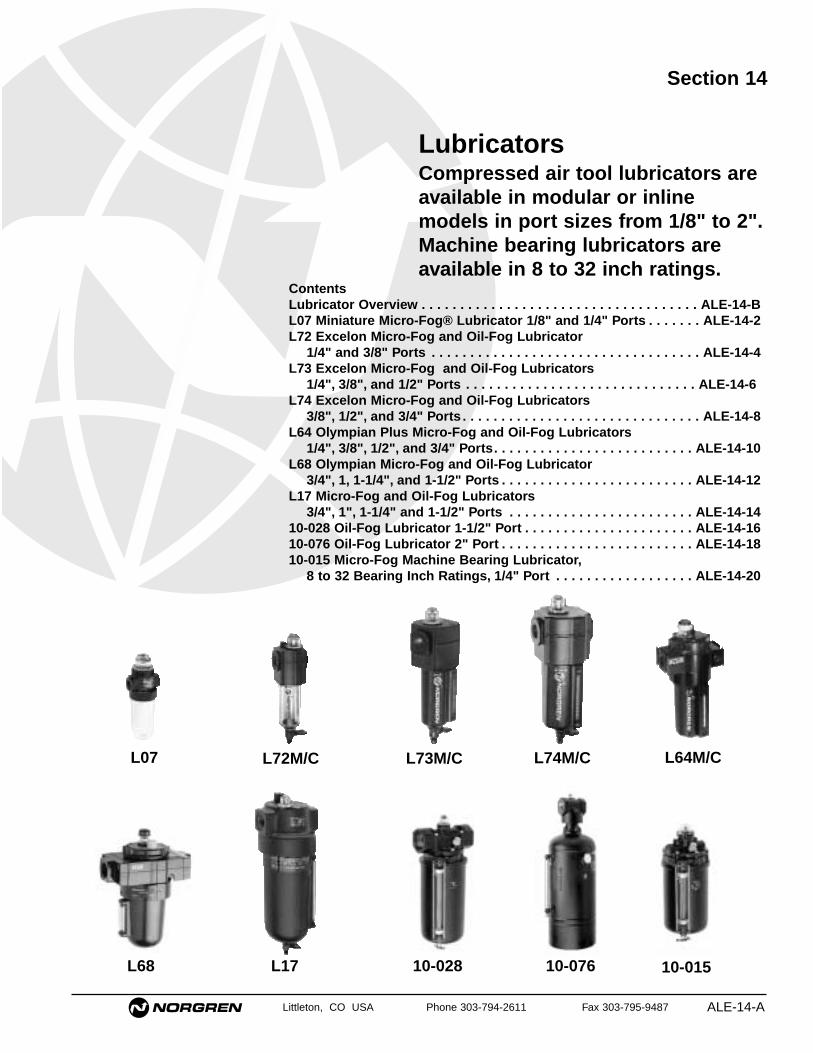
Littleton, CO USA Phone 303-794-2611 Fax 303-795-9487 ALE-14-A
Section 14
ContentsLubricator Overview . . . . . . . . . . . . . . . . . . . . . . . . . . . . . . . . . . . . ALE-14-BL07 Miniature Micro-Fog® Lubricator 1/8" and 1/4" Ports . . . . . . . ALE-14-2L72 Excelon Micro-Fog and Oil-Fog Lubricator
1/4" and 3/8" Ports . . . . . . . . . . . . . . . . . . . . . . . . . . . . . . . . . . . ALE-14-4L73 Excelon Micro-Fog and Oil-Fog Lubricators
1/4", 3/8", and 1/2" Ports . . . . . . . . . . . . . . . . . . . . . . . . . . . . . . ALE-14-6L74 Excelon Micro-Fog and Oil-Fog Lubricators
3/8", 1/2", and 3/4" Ports . . . . . . . . . . . . . . . . . . . . . . . . . . . . . . . ALE-14-8L64 Olympian Plus Micro-Fog and Oil-Fog Lubricators
1/4", 3/8", 1/2", and 3/4" Ports. . . . . . . . . . . . . . . . . . . . . . . . . . ALE-14-10L68 Olympian Micro-Fog and Oil-Fog Lubricator
3/4", 1, 1-1/4", and 1-1/2" Ports . . . . . . . . . . . . . . . . . . . . . . . . . ALE-14-12L17 Micro-Fog and Oil-Fog Lubricators
3/4", 1", 1-1/4" and 1-1/2" Ports . . . . . . . . . . . . . . . . . . . . . . . . ALE-14-1410-028 Oil-Fog Lubricator 1-1/2" Port . . . . . . . . . . . . . . . . . . . . . . ALE-14-1610-076 Oil-Fog Lubricator 2" Port . . . . . . . . . . . . . . . . . . . . . . . . . ALE-14-1810-015 Micro-Fog Machine Bearing Lubricator,
8 to 32 Bearing Inch Ratings, 1/4" Port . . . . . . . . . . . . . . . . . . ALE-14-20
LubricatorsCompressed air tool lubricators areavailable in modular or inlinemodels in port sizes from 1/8" to 2".Machine bearing lubricators areavailable in 8 to 32 inch ratings.
L07 L64M/C
L68 L17 10-028 10-076 10-015
L74M/CL73M/CL72M/C
Lubricator Overview
Littleton, CO USA Phone 303-794-2611 Fax 303-795-9487ALE-14-B
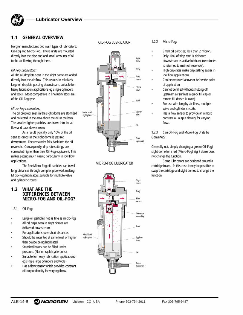
1.1 GENERAL OVERVIEW
Norgren manufactures two main types of lubricators:Oil-Fog and Micro-Fog. These units are mounteddirectly into the pipe and add small amounts of oilto the air flowing through them.
Oil Fog-Lubricators:All the oil droplets seen in the sight dome are addeddirectly into the air flow. This results in relativelylarge oil droplets passing downstream, suitable forheavy lubrication applications eg single cylindersand tools. Most competitive in line lubricators areof the Oil-Fog type.
Micro-Fog Lubricators:The oil droplets seen in the sight dome are atomizedand collected in the area above the oil in the bowl.The smaller lighter particles are drawn into the airflow and pass downstream.
As a result typically only 10% of the oilseen as drops in the sight dome is passeddownstream. The remainder falls back into the oilreservoir. Consequently, drip rate settings aresomewhat higher than their Oil-Fog equivalent. Thismakes setting much easier, particularly in low flowapplications.
The fine Micro-Fog oil particles can travellong distances through complex pipe work makingMicro-Fog lubricators suitable for multiple valveand cylinder circuits.
1.2 WHAT ARE THEDIFFERENCES BETWEENMICRO-FOG AND OIL-FOG?
1.2.1 Oil-Fog:
• Large oil particles not as fine as micro-fog.• All oil drips seen in sight domes are
delivered downstream.• For applications over short distances.• Should be mounted at same level or higher
than device being lubricated.• Standard bowls can be filled under
pressure. (Not on rapid cycle units).• Suitable for heavy lubrication applications
eg single large cylinders and tools.• Has a flow sensor which provides constant
oil output density for varying flows.
OIL-FOG LUBRICATOR
MICRO-FOG LUBRICATOR
Sightdome
Body
Flowsensor
Generatorassembly
Bowl
Syphontube
Oil
Drain(optional)
Metal bowlsight glass
Sightdome
Body
Flowsensor
Check valve
Bowl
Syphontube
Oil
Drain(optional)
Metal bowlsight glass
1.2.2 Micro-Fog:
• Small oil particles; less than 2 micron.• Only 10% of ‘drip rate’ is delivered
downstream as active lubricant (remainderis returned to main oil reservoir).
• High drip rates make drip setting easier inlow flow applications.
• Can be mounted above or below the pointof application.
• Cannot be filled without shutting offupstream air (unless a quick fill cap orremote fill device is used).
• For use with lengthy air lines, multiplevalve and cylinder circuits.
• Has a flow sensor to provide an almostconstant oil output density for varyingflows.
1.2.3 Can Oil-Fog and Micro-Fog Units beConverted?
Generally not, simply changing a green (Oil-Fog)sight dome for a red (Micro-Fog) sight dome doesnot change the function.
Some lubricators are designed around acartridge insert. In this case it may be possible toswap the cartridge and sight domes to change thefunction.
Lubricator Overview
Littleton, CO USA Phone 303-794-2611 Fax 303-795-9487 ALE-14-C
1.4 SETTING LUBRICATOR DRIP RATES
1.4.1 What is the Correct Drip Rate Setting?
The drip rate will depend on the application, theamount of lubrication required, the flow through thelubricator and the lubricator type. In Micro-Foglubricators only 10% of the droplets in the sightdome are carried downstream. The drip rate inMicro-Fog lubricators therefore tends to be muchhigher.
The following table can be used to estimatedrip rate for required flow. This is very much a ruleof thumb. In practice it is necessary to fine tune theoil drip rate in each application.
Typical Drip Rate Typical Drip Rate Approx per Minute per Minute Flow Micro-Fog Oil-Fog scfm
(dm3/s)
20 2 10 (5)40 4 20 (10)60 6 30 (15)80 8 40 (20)100 10 50 (25)120 12 60 (30)
1.3.2 Can the Drip Rate be Shut Off?
In lubricators with needle valve type sight dome,yes.
Some Norgren sight domes use a felt padwhich is soaked in oil at the point where the dropsare formed. With this type of sight dome the oildroplets cease once the felt pad dries out.
With the new style dome (L72/73/74 andL07) complete shut off is not possible. Minimumadjustment for the drip rate is around 1 drop perminute.
1.5 FILLING METHODS
1.5.1 Oil-Fog and Micro-Fog Lubricators:
The standard Oil-Fog lubricators can be filled underpressure ie without switching off the upstream air.When a fill plug is removed a check valve in thelubricator body isolates the inlet pressure from thebowl and the reservoir will depressurize. Thelubricator can then be filled with oil. When the fillplug is replaced, the reservoir will re-pressurize.
The standard Micro-Fog unit can only befilled without isolating the upstream pressure if aremote fill or quick fill nipple accessory is fitted. Toremove the fill plug of a Micro-Fog lubricator whilseunder pressure can be dangerous. If in doubt shutoff the upstream air!
1.5.2 Remote Fill Devices:
The remote oil fill system provides a means of fillingfrom a remote fill point, a single lubricator or a bankof lubricators manifolded together. The remote fillpoint may be connected to a portable reservoir or toa centralized, permanent reservoir. A portablereservoir permits the use of different lubricants indifferent groups of lubricators to suit therequirements of the machinery being lubricated. Thelubrication oil must be fed in at a higher pressurethan exists in the bowl.
The devices are NOT intended forconnection to an oil feed line which is underconstant pressure from a pump or pressurizedreservoir. The device cannot reset until the pressureis removed. Such lines are a potential safety hazardif they should leak or become broken.
1.5.3 Quick Fill Nipples:
The quick fill system is an alternative which allowsease of filling a single Micro-Fog or Oil-Foglubricator without switching off the mains air (onsome units the quick fill nipple replaces the fillerplug).
To fill the lubricator, a quick fill connectorpiped to a portable oil reservoir is snapped in placeover the quick fill nipple. The main oil reservoir cannow be pumped (or pressurized) to a pressuregreater than the lubricator bowl and the lubricatorfilled.
1.3 LUBRICATOR SIZING
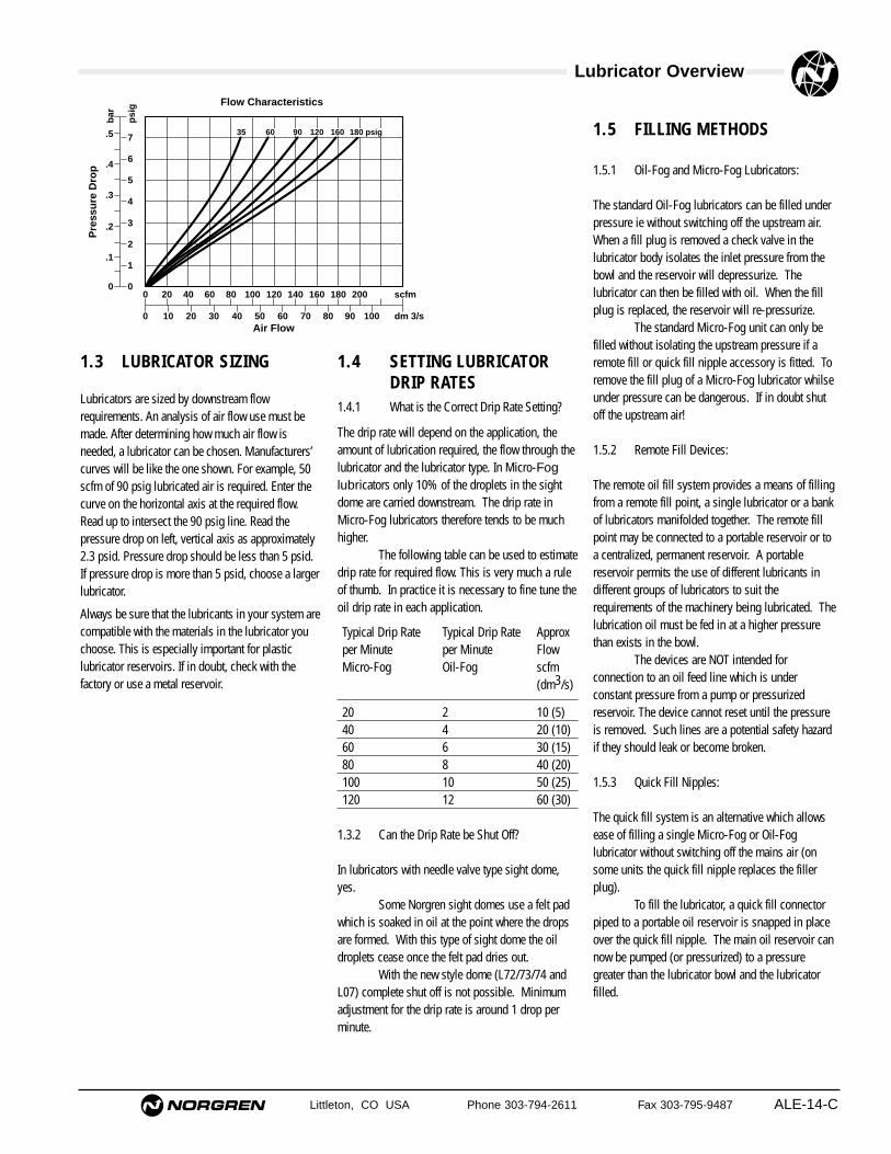
Lubricators are sized by downstream flowrequirements. An analysis of air flow use must bemade. After determining how much air flow isneeded, a lubricator can be chosen. Manufacturers’curves will be like the one shown. For example, 50scfm of 90 psig lubricated air is required. Enter thecurve on the horizontal axis at the required flow.Read up to intersect the 90 psig line. Read thepressure drop on left, vertical axis as approximately2.3 psid. Pressure drop should be less than 5 psid.If pressure drop is more than 5 psid, choose a largerlubricator.
Always be sure that the lubricants in your system arecompatible with the materials in the lubricator youchoose. This is especially important for plasticlubricator reservoirs. If in doubt, check with thefactory or use a metal reservoir.
00
0 10 20 30 40 50Air Flow
Flow Characteristics
60 70 80 90 100
20 40 60 80 100 120 140 160 180 200 scfm
dm 3/s
0
.1
.2
.3
.4
.5
bar
psi
g
1
2
3
4
5
6
7
Pre
ssu
re D
rop
35 60 90 120 160 180 psig
Lubricator Overview
Littleton, CO USA Phone 303-794-2611 Fax 303-795-9487ALE-14-D
1.6 OPTIONS AND ACCESSORIES
1.6.1 Where can Liquid Level Switches beFitted?
Liquid level detection methods can be attached tothe 1 quart bowl and 2 & 5 gallon tanks.
1.6.2 Where can Remote Fill and Liquid LevelSwitches be Fitted?
The smaller bowls, L73 and up, are all capable ofeither remote fill or liquid level detection (but notboth at the same time!). The 2 quart and 2 & 5gallon tanks only can have the liquid level switchesfitted.
1.6.3 How do Liquid Level Switches Work?
Liquid level switches are bipolar reed switcheswhich change state when the float rises and falls.
Liquid level switches are normallyconnected to give an electrical signal when the floatfalls (ie when the liquid level is too low). In criticalapplications the logic could be reversed. Maximumand minimum settings are possible too.
1.7 LARGE TANKS/RESERVOIRS
1.7.1 Which Units have Large Tanks/Reservoirs?
All units in basic 1/2” and above have optionallarger bowls/tanks.
Olympian Plus and Excelon 74 are limitedto 1 quart as standard. For 2 and 5 gallon capacityuse 15/17 Series, or the 10-028/-076 (2”)lubricators.
1.8 APPLICATION SPECIFICUNITS
1.8.1 Do we Make Bearing Lubricators?
These are aerosol type lubricators. Theselubricators use air to get the oil to the point oflubrication, however the tool or application is notpowered by the air. Although produced by Norgren,systems for their application are designed and soldby Engineering and General Lubrication Systems.
1.8.2 What is a Fixed Venturi (Bi-Directional)Lubricator?
Standard Norgren lubricators use a flow sensor toachieve constant oil density with varying flows. Insome applications high flow is more important thanconstant density and a fixed venturi can be usedinstead of a flow sensor. It may also be useful insystems with rapid cycling. Consult Air Line formore details.
1.9 OILS
1.9.1 What Oils are Recommended?
Recommended oils fall into 2 categories:-1 Oils recommended for use with all Norgren
units (valves, cylinders, fittings and FRL’s).2 Oils which can be used with Norgren
lubricators but not necessarily with otherNorgren equipment.
Refer to ALE-29-2 for recommended lubricants.
1.9.2 Can Non-Recommended Oils be Used?
Some oils can be tested for suitability, but Norgrencannot be responsible for use of non-recommendedlubricants.
Lubricators Overview
Littleton, CO USA Phone 303-794-2611 Fax 303-795-9487 ALE-14-E
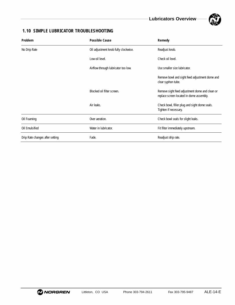
Problem
No Drip Rate
Oil Foaming
Oil Emulsified
Drip Rate changes after setting
Possible Cause
Oil adjustment knob fully clockwise.
Low oil level.
Airflow through lubricator too low.
Blocked oil filter screen.
Air leaks.
Over aeration.
Water in lubricator.
Fade.
Remedy
Readjust knob.
Check oil level.
Use smaller size lubricator.
Remove bowl and sight feed adjustment dome andclear syphon tube.
Remove sight feed adjustment dome and clean orreplace screen located in dome assembly.
Check bowl, filler plug and sight dome seals.Tighten if necessary.
Check bowl seals for slight leaks.
Fit filter immediately upstream.
Readjust drip rate.
1.10 SIMPLE LUBRICATOR TROUBLESHOOTING
See Section ALE-25 for Accessories
Littleton, CO USA Phone 303-794-2611 Fax 303-795-9487
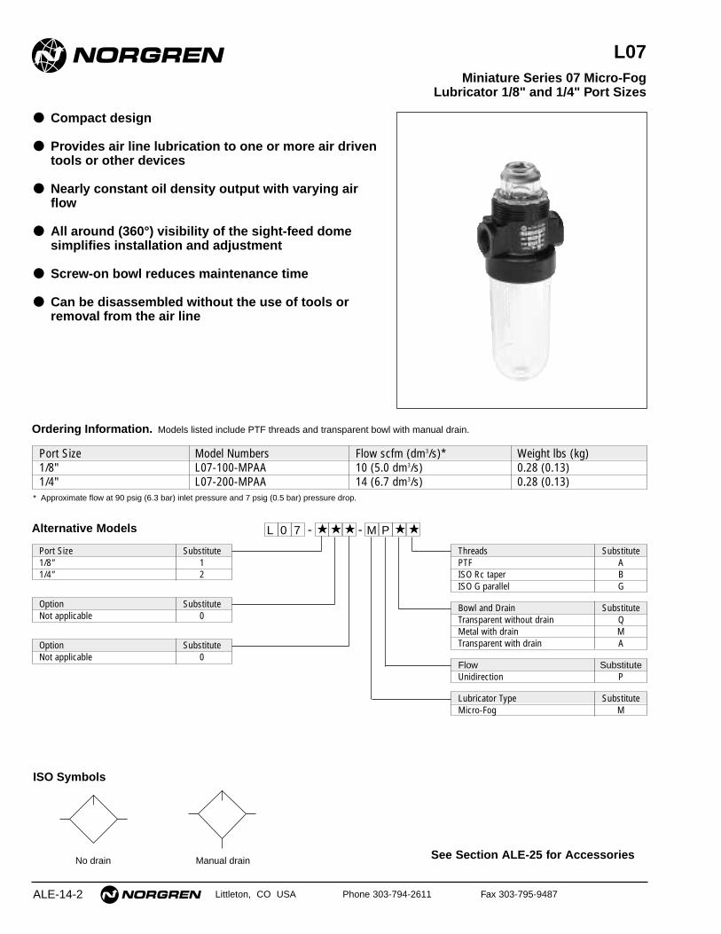
L07
● Compact design
● Provides air line lubrication to one or more air driventools or other devices
● Nearly constant oil density output with varying airflow
● All around (360°) visibility of the sight-feed domesimplifies installation and adjustment
● Screw-on bowl reduces maintenance time
● Can be disassembled without the use of tools orremoval from the air line
Miniature Series 07 Micro-Fog Lubricator 1/8" and 1/4" Port Sizes
ALE-14-2
ISO Symbols
No drain Manual drain
Port Size Model Numbers Flow scfm (dm3/s)* Weight lbs (kg)1/8" L07-100-MPAA 10 (5.0 dm3/s) 0.28 (0.13)1/4" L07-200-MPAA 14 (6.7 dm3/s) 0.28 (0.13)
Ordering Information. Models listed include PTF threads and transparent bowl with manual drain.
* Approximate flow at 90 psig (6.3 bar) inlet pressure and 7 psig (0.5 bar) pressure drop.
Alternative Models
Port Size Substitute1/8" 11/4" 2
Threads SubstitutePTF AISO Rc taper BISO G parallel G
Option SubstituteNot applicable 0
Bowl and Drain SubstituteTransparent without drain QMetal with drain MTransparent with drain AOption Substitute
Not applicable 0Flow SubstituteUnidirection P
Lubricator Type SubstituteMicro-Fog M
- ★PM ★★ ★ -0 ★L 7
L07 Lubricators
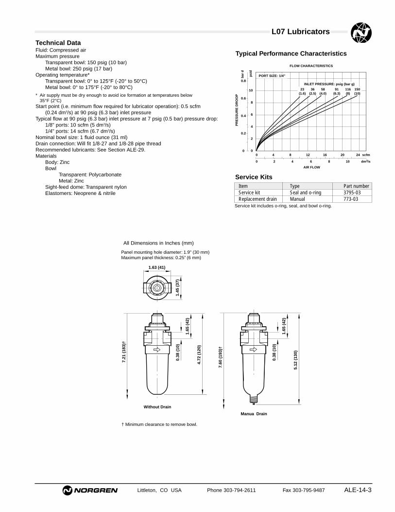
Littleton, CO USA Phone 303-794-2611 Fax 303-795-9487 ALE-14-3
All Dimensions in Inches (mm)
Technical DataFluid: Compressed airMaximum pressure
Transparent bowl: 150 psig (10 bar)Metal bowl: 250 psig (17 bar)
Operating temperature*Transparent bowl: 0° to 125°F (-20° to 50°C)Metal bowl: 0° to 175°F (-20° to 80°C)
* Air supply must be dry enough to avoid ice formation at temperatures below 35°F (2°C)
Start point (i.e. minimum flow required for lubricator operation): 0.5 scfm (0.24 dm3/s) at 90 psig (6.3 bar) inlet pressure
Typical flow at 90 psig (6.3 bar) inlet pressure at 7 psig (0.5 bar) pressure drop:1/8" ports: 10 scfm (5 dm3/s) 1/4" ports: 14 scfm (6.7 dm3/s)
Nominal bowl size: 1 fluid ounce (31 ml)Drain connection: Will fit 1/8-27 and 1/8-28 pipe threadRecommended lubricants: See Section ALE-29.Materials
Body: ZincBowl
Transparent: PolycarbonateMetal: Zinc
Sight-feed dome: Transparent nylonElastomers: Neoprene & nitrile
Typical Performance Characteristics
PORT SIZE: 1/4"
INLET PRESSURE: psig (bar g)
FLOW CHARACTERISTICS
0 2 4 6 8 10 dm3/s
AIR FLOW
0 4 8 12 16 20 24 scfm
PR
ES
SU
RE
DR
OO
P
0.8
0.6
0.4
0.2
0
bar
d
10
8
6
4
2
0
psi
d
36(2.5)
23(1.6)
91(6.3)
58(4.0)
150(10)
116(8)
1.63 (41)
1.45
(37
)
7.21
(18
3)†
0.38
(10
)
1.65
(42
)
4.72
(12
0)
Manua Drain
Without Drain
7.60
(19
3)†
0.38
(10
)
1.65
(42
)
5.12
(13
0)
† Minimum clearance to remove bowl.
Service KitsItem Type Part numberService kit Seal and o-ring 3795-03Replacement drain Manual 773-03
Service kit includes o-ring, seal, and bowl o-ring.
Panel mounting hole diameter: 1.9" (30 mm)Maximum panel thickness: 0.25” (6 mm)
See Section ALE-25 for Accessories
Littleton, CO USA Phone 303-794-2611 Fax 303-795-9487
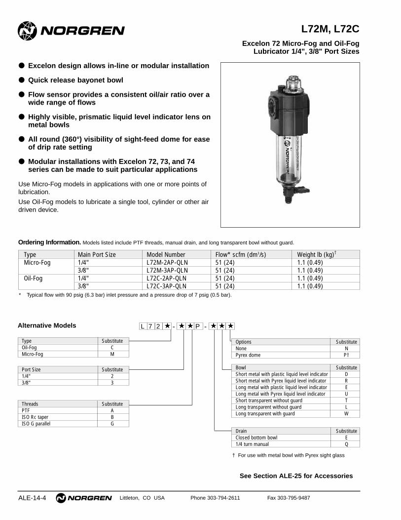
L72M, L72C
● Excelon design allows in-line or modular installation
● Quick release bayonet bowl
● Flow sensor provides a consistent oil/air ratio over awide range of flows
● Highly visible, prismatic liquid level indicator lens onmetal bowls
● All round (360°) visibility of sight-feed dome for easeof drip rate setting
● Modular installations with Excelon 72, 73, and 74series can be made to suit particular applications
Use Micro-Fog models in applications with one or more points oflubrication.
Use Oil-Fog models to lubricate a single tool, cylinder or other airdriven device.
Excelon 72 Micro-Fog and Oil-Fog Lubricator 1/4", 3/8" Port Sizes
ALE-14-4
Alternative Models L 7 2 -★ ★ ★ - ★P ★ ★
Type SubstituteOil-Fog CMicro-Fog M
Threads SubstitutePTF AISO Rc taper BISO G parallel G
Port Size Substitute1/4" 23/8" 3
Options SubstituteNone NPyrex dome P†
Drain SubstituteClosed bottom bowl E1/4 turn manual Q
† For use with metal bowl with Pyrex sight glass
Bowl SubstituteShort metal with plastic liquid level indicator DShort metal with Pyrex liquid level indicator RLong metal with plastic liquid level indicator ELong metal with Pyrex liquid level indicator UShort transparent without guard TLong transparent without guard LLong transparent with guard W
Ordering Information. Models listed include PTF threads, manual drain, and long transparent bowl without guard.
* Typical flow with 90 psig (6.3 bar) inlet pressure and a pressure drop of 7 psig (0.5 bar).
Type Main Port Size Model Number Flow* scfm (dm3/s) Weight lb (kg)†
Micro-Fog 1/4" L72M-2AP-QLN 51 (24) 1.1 (0.49)3/8" L72M-3AP-QLN 51 (24) 1.1 (0.49)
Oil-Fog 1/4" L72C-2AP-QLN 51 (24) 1.1 (0.49)3/8" L72C-3AP-QLN 51 (24) 1.1 (0.49)
L72M/C Lubricators
Littleton, CO USA Phone 303-794-2611 Fax 303-795-9487 ALE-14-5
All Dimensions in Inches (mm)
Technical DataFluid: Compressed airMaximum pressure:
Transparent bowl: 150 psig (10 bar)Metal bowl: 250 psig (17 bar)
Operating temperature*:Transparent bowl: 0° to 125°F (-20° to 50°C)Metal bowl: 0° to 150°F (-20° to 65°C)
* Air supply must be dry enough to avoid ice formation at temperatures below 35°F (2°C).
Start point (i.e. minimum flow required for lubricator operation) at 90 psig (6.3 bar)inlet pressure:Micro-Fog: 2.0 scfm (0.94 dm3/s)Oil-Fog: 1.0 scfm (0.47 dm3/s)
Typical flow at 90 psig (6.3 bar) inlet pressure and 7 psig (0.5 bar) pressure drop: 51 scfm (24 dm3/s)
Nominal reservoir capacity:Short bowl: 1.9 fluid ounce (56 ml)Long bowl: 2.2 fluid ounce (65 ml)
Manual drain connection: Will fit 1/8-27 and 1/8-28 pipe threadRecommended lubricants: See Section ALE-29.Materials:
Body: ZincReservoir:
Transparent: PolycarbonateGuard for transparent reservoir: ZincMetal: Zinc
Metal reservoir liquid level indicator lens:Transparent nylon
Sight-feed dome: Transparent nylonElastomers: Neoprene, nitrile, and Geolast®
Typical Performance Characteristics
INLET PRESSURE: psig (bar g)
FLOW CHARACTERISTICS
0 5 10 15 20 25 dm3/s
AIR FLOW
0 10 20 30 40 50 60 scfm
PR
ES
SU
RE
DR
OP
0.8
0.6
0.4
0.2
0
bar
d
10
8
6
4
2
0
psi
d
PORT SIZE 1/4"
36(2.5)
58(4.0)
91(6.3)
116(8.0)
150(10.0)
Short Bowl with 1/4 Turn Manual Drain
Long Bowl with Closed Bottom
Oil-FogMicro-Fog
1.98 (50)
1.91
(48
)
Short Bowl with Closed Bottom
Long Bowl with 1/4 Turn Manual Drain
5.27
(13
4)
8.58
(21
8)**
1.63
(41
)
2.51
(64
) †
0.75
(19
)
5.83
(14
8)
9.13
(23
2)**
4.49
(11
4)
7.79
(19
8)**
5.04
(12
8)
8.35
(21
2)**
** Minimum clearance required to remove bowl.
† Optional pyrex sight-feed dome.
Service KitsItem Type Part NumberService kit Seal and gasket 4382-500Liquid level lens kit Prismatic 4380-030Replacement drains 1/4 turn manual 619-50
Service kit includes plug o-ring, sight-feed dome seal, manual drain o-ring and bowl o-ring.
See Section ALE-25 for Accessories
Littleton, CO USA Phone 303-794-2611 Fax 303-795-9487
L73M, L73C
● Excelon design allows in-line or modular installation
● Quick release bayonet bowl
● Flow sensor design provides a nearly constant oil/airratio over a wide range of air flows
● Highly visible, prismatic liquid level indicator lens
● All around (360°) visibility of the sight-feed domesimplifies installation and adjustment
● Modular installations with Excelon 72, 73, and 74series can be made to suit particular applications
Use Micro-Fog models in applications containing one or morepoints of lubrication.Use Oil-Fog models to lubricate a single tool, cylinder, or other airdriven device.
Excelon 73 Micro-Fog and Oil-FogLubricators 1/4", 3/8", 1/2" Port Sizes
ALE-14-6
Alternative Models
Ordering Information. Models listed include PTF threads, manual drain, and metal bowl with plastic liquid level indicator.
* Maximum recommended air flow. Higher flows create excessive air velocity, turbulence, and pressure losses.
Type Main Port Size Model Number Flow* scfm (dm3/s) Weight lb (kg)
Micro-Fog1/4" L73M-2AP-QDN 60 (28) 1.1 (0.50)3/8" L73M-3AP-QDN 60 (28) 1.1 (0.50)1/2" L73M-4AP-QDN 60 (28) 1.1 (0.50)
Oil-Fog1/4" L73C-2AP-QDN 60 (28) 1.1 (0.50)3/8" L73C-3AP-QDN 60 (28) 1.1 (0.50)1/2" L73C-4AP-QDN 60 (28) 1.1 (0.50)
L 7 3 -★ ★ ★ - ★★ ★ ★
Threads SubstitutePTF AISO Rc taper BISO G parallel G
Air Flow Direction SubstituteUni-directional P
Options SubstituteNone NPyrex sight-feed dome † PQuick fill nipple Q
Type SubstituteOil-Fog CMicro-Fog M
Bowl SubstituteMetal with plastic liquid level indicator DTransparent with guard PMetal with Pyrex liquid level indicator† RTransparent T
Drain SubstituteClosed bottom EManual 1/4 turn Q
Port Size Substitute1/4" 23/8" 31/2" 4
† Order optional Pyrex sight-feed dome when ordering metal bowl with Pyrex liquid level indicator.
L73M/C Lubricators
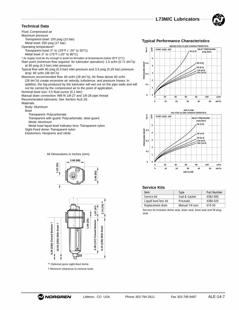
Littleton, CO USA Phone 303-794-2611 Fax 303-795-9487 ALE-14-7
All Dimensions in Inches (mm)
Technical DataFluid: Compressed airMaximum pressure
Transparent bowl: 150 psig (10 bar)Metal bowl: 250 psig (17 bar)
Operating temperature*Transparent bowl: 0° to 125°F ( -20° to 50°C)Metal bowl: 0° to 175°F (-20° to 80°C)
* Air supply must be dry enough to avoid ice formation at temperatures below 35°F (2°C).Start point (minimum flow required for lubricator operation): 1.5 scfm (0.71 dm
3/s)
at 90 psig (6.3 bar) inlet pressureTypical flow with 90 psig (6.3 bar) inlet pressure and 3.5 psig (0.25 bar) pressure
drop: 80 scfm (38 dm3/s)
Maximum recommended flow: 60 scfm (28 dm3/s). Air flows above 60 scfm
(28 dm3/s) create excessive air velocity, turbulence, and pressure losses. In
addition, the fog produced by the lubricator will wet out on the pipe walls and willnot be carried by the compressed air to the point of application.
Nominal bowl size: 3.5 fluid ounce (0.1 liter)Manual drain connection: Will fit 1/8-27 and 1/8-28 pipe threadRecommended lubricants: See Section ALE-29.Materials
Body: AluminumBowl
Transparent: PolycarbonateTransparent with guard: Polycarbonate, steel guardMetal: AluminumMetal bowl liquid level indicator lens: Transparent nylon
Sight-Feed dome: Transparent nylonElastomers: Neoprene and nitrile
PR
ES
SU
RE
DR
OP 0.3
0.2
0.1
0
bar
d
5
4
3
2
1
0
psi
d
PORT SIZE: 3/8"
0 10 20 30 40 50 dm3/s
0 20 40 60 80 100 scfm
MICRO-FOG FLOW CHARACTERISTICS
150 (10.0)116 (8.0)90 (6.3)
58 (4.0)
INLET PRESSURE:psig (bar)36 (2.5)
PR
ES
SU
RE
DR
OP 0.3
0.2
0.1
0
bar
d
5
4
3
2
1
0
psi
d
PORT SIZE: 3/8"
0 10 20 30 40 50 dm3/s
AIR FLOW
0 20 40 60 80 100 scfm
AIR FLOWOIL-FOG FLOW CHARACTERISTICS
150 (10.0)116 (8.0)90 (6.3)
58 (4.0)
36 (2.5)
INLET PRESSURE:psig (bar)
Typical Performance Characteristics
10.0
4 (2
55)
Wit
h D
rain
†
2.68 (68)
2.45
(62
)1.22
(31
)
2.74
(70
) **
1.87
(47
)
1.00
(25
)
5.38
(13
7) C
lose
d B
ott
om
6.15
(15
6) W
ith
Dra
in
9.29
(23
6) C
lose
d B
ott
om
†
Service kit includes dome seal, drain seal, bowl seal and fill plugseal.
Service KitsItem Type Part NumberService kit Seal & Gasket 4382-600Liquid level lens kit Prismatic 4380-020Replacement drain Manual 1/4 turn 619-50
** Optional pyrex sight-feed dome.
† Minimum clearance to remove bowl.
Littleton, CO USA Phone 303-794-2611 Fax 303-795-9487
L74M, L74C
● Excelon design allows in-line or modular installation
● Quick release bayonet bowl
● Highly visible, prismatic liquid level indicator lens
● Flow sensor design provides a nearly constant oil/airratio over a wide range of air flows
● All around (360°) visibility of the sight-feed domesimplifies installation and adjustment
● Modular installations with Excelon 72, 73, and 74series can be made to suit particular applications
Use Micro-Fog models in applications with one or more points oflubrication.Use Oil-Fog models to lubricate a single tool, cylinder, or other airdriven device.
Excelon 74 Micro-Fog and Oil-Fog Lubricators 3/8", 1/2", 3/4" Port Sizes
ALE-14-8
Alternative Models L 7 4 -★ ★ ★ - ★★ ★ ★
Threads SubstitutePTF AISO Rc taper BISO G parallel G
Air Flow Direction SubstituteBi-directional (Oil-Fog only) EUni-directional P
Options SubstituteLow oil level switch *** LNone NPyrex dome *† PQuick fill nipple Q
Type SubstituteOil-Fog CMicro-Fog M
Bowl Substitute1 quart US (1 liter) metal with Pyrex liquid level indicator †† A
7 fluid oz. (0.2 liter) metal with plastic liquid level indicator D
7 fluid oz. (0.2 liter) transparent with guard P
7 fluid oz. (0.2 liter) metal with Pyrex liquid level indicator†† R
Drain SubstituteClosed bottom EManual 1/4 turn QRemote fill device - Use onlywith 7 fluid oz. (0.2 liter) bowl. R
Port Size Substitute3/8" 31/2" 43/4" 6
*** Low oil level switch requires 1 litre bowl, type ‘A’ at 9th digit.*† Pyrex dome used only with bowl type ‘A’ or ‘R’ at 9th digit.†† Pyrex liquid level indicator used only with option ‘P’ at 10th digit.
Ordering Information. Models listed include PTF threads, manual drain, and 7 fluid ounce (0.2 liter) metal bowl with plastic liquid level indicator.
* Models listed in the order table must not be located downstream of frequently cycling directional control valves. Order the optional bi-directional Oil-Fog Lubricatorfor use under such conditions.
** Typical flow with 90 psig (6.3 bar) inlet pressure and a pressure drop of 7 psig (0.5 bar).† Lubricators with 1 quart (1 litre) metal bowl: Add 2.01 lbs (0.91 kg).
Type Main Port Size Model Number * Flow** scfm (dm3/s) Weight lb (kg)†
Micro-Fog3/8" L74M-3AP-QDN 114 (54) 1.70 (0.77)1/2" L74M-4AP-QDN 154 (73) 1.61 (0.73)3/4" L74M-6AP-QDN 142 (67) 1.55 (0.71)
Oil-Fog3/8" L74C-3AP-QDN 118 (56) 1.70 (0.77)1/2" L74C-4AP-QDN 192 (91) 1.61 (0.73)3/4" L74C-6AP-QDN 186 (88) 1.55 (0.71)
See Section ALE-25 for Accessories
L74M/C Lubricators
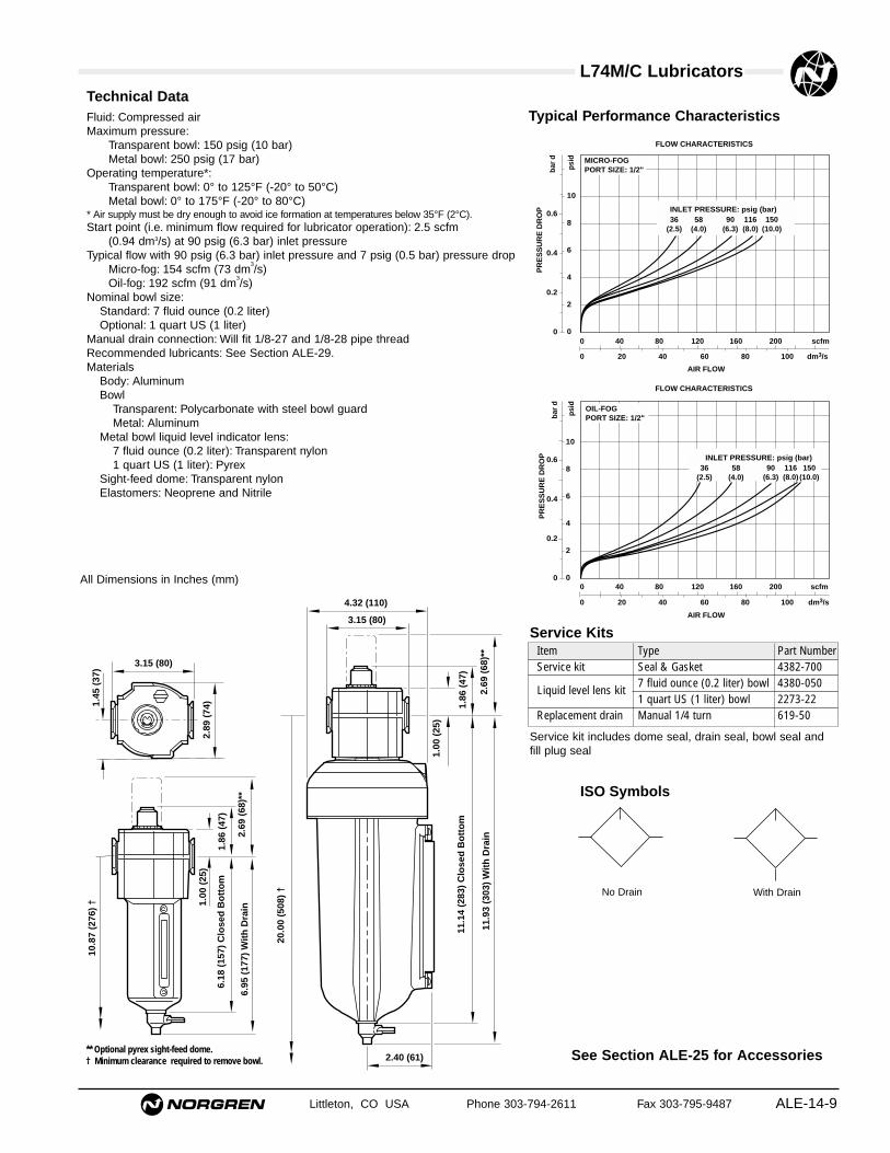
Littleton, CO USA Phone 303-794-2611 Fax 303-795-9487 ALE-14-9
All Dimensions in Inches (mm)
Technical DataFluid: Compressed airMaximum pressure:
Transparent bowl: 150 psig (10 bar)Metal bowl: 250 psig (17 bar)
Operating temperature*:Transparent bowl: 0° to 125°F (-20° to 50°C)Metal bowl: 0° to 175°F (-20° to 80°C)
* Air supply must be dry enough to avoid ice formation at temperatures below 35°F (2°C).Start point (i.e. minimum flow required for lubricator operation): 2.5 scfm
(0.94 dm3/s) at 90 psig (6.3 bar) inlet pressureTypical flow with 90 psig (6.3 bar) inlet pressure and 7 psig (0.5 bar) pressure drop
Micro-fog: 154 scfm (73 dm3/s)
Oil-fog: 192 scfm (91 dm3/s)
Nominal bowl size:Standard: 7 fluid ounce (0.2 liter)Optional: 1 quart US (1 liter)
Manual drain connection: Will fit 1/8-27 and 1/8-28 pipe threadRecommended lubricants: See Section ALE-29.Materials
Body: AluminumBowl
Transparent: Polycarbonate with steel bowl guardMetal: Aluminum
Metal bowl liquid level indicator lens:7 fluid ounce (0.2 liter): Transparent nylon1 quart US (1 liter): Pyrex
Sight-feed dome: Transparent nylon Elastomers: Neoprene and Nitrile
ISO Symbols
No Drain With Drain
0.6
0.4
0.2
0
PR
ES
SU
RE
DR
OP
bar
d
10
8
6
4
2
0
psi
d MICRO-FOGPORT SIZE: 1/2"
36(2.5)
58(4.0)
150(10.0)
90(6.3)
116(8.0)
INLET PRESSURE: psig (bar)
0 20 40 60 80 100 dm3/s
AIR FLOW
0 40 80 120 160 200 scfm
FLOW CHARACTERISTICS
0.6
0.4
0.2
0
PR
ES
SU
RE
DR
OP
bar
d
10
8
6
4
2
0 p
sid
OIL-FOGPORT SIZE: 1/2"
36(2.5)
58(4.0)
150(10.0)
90(6.3)
116(8.0)
INLET PRESSURE: psig (bar)
0 20 40 60 80 100 dm3/s
AIR FLOW
0 40 80 120 160 200 scfm
FLOW CHARACTERISTICS
Typical Performance Characteristics
2.40 (61)
4.32 (110)
3.15 (80)
11.1
4 (2
83)
Clo
sed
Bo
tto
m
1.00
(25
)
1.86
(47
)
20.0
0 (5
08)
†
2.89
(74
)1.
00 (
25)
1.45
(37
) 3.15 (80)
6.18
(15
7) C
lose
d B
ott
om
1.86
(47
)
10.8
7 (2
76)
†
6.95
(17
7) W
ith
Dra
in
11.9
3 (3
03)
Wit
h D
rain2.
69 (
68)*
*
** Optional pyrex sight-feed dome.† Minimum clearance required to remove bowl.
2.69
(68
)**
Service kit includes dome seal, drain seal, bowl seal andfill plug seal
Service KitsItem Type Part NumberService kit Seal & Gasket 4382-700
Liquid level lens kit7 fluid ounce (0.2 liter) bowl 4380-0501 quart US (1 liter) bowl 2273-22
Replacement drain Manual 1/4 turn 619-50
See Section ALE-25 for Accessories
Littleton, CO USA Phone 303-794-2611 Fax 303-795-9487
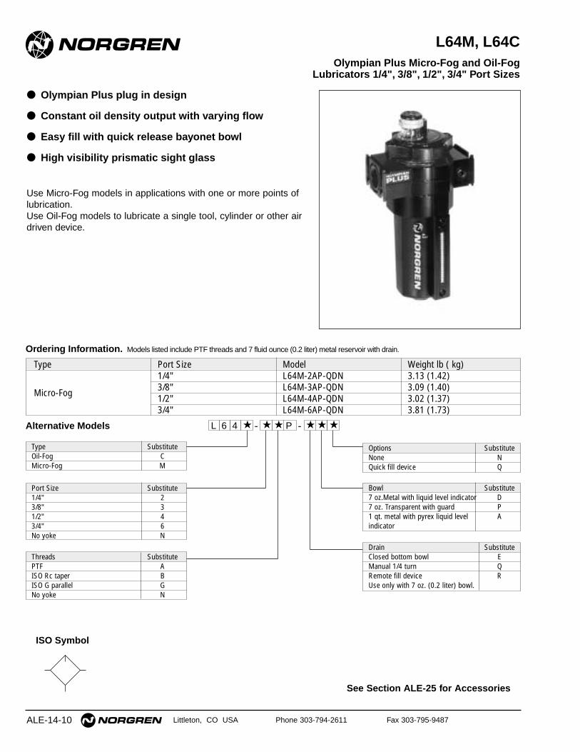
L64M, L64C
● Olympian Plus plug in design
● Constant oil density output with varying flow
● Easy fill with quick release bayonet bowl
● High visibility prismatic sight glass
Use Micro-Fog models in applications with one or more points oflubrication.Use Oil-Fog models to lubricate a single tool, cylinder or other airdriven device.
Olympian Plus Micro-Fog and Oil-Fog Lubricators 1/4", 3/8", 1/2", 3/4" Port Sizes
ALE-14-10
ISO Symbol
Ordering Information. Models listed include PTF threads and 7 fluid ounce (0.2 liter) metal reservoir with drain.
Type Port Size Model Weight lb ( kg)1/4" L64M-2AP-QDN 3.13 (1.42)
Micro-Fog 3/8" L64M-3AP-QDN 3.09 (1.40)1/2" L64M-4AP-QDN 3.02 (1.37)3/4" L64M-6AP-QDN 3.81 (1.73)
L 6 4 -★ ★ ★ - ★P ★ ★
Type SubstituteOil-Fog CMicro-Fog M
Threads SubstitutePTF AISO Rc taper BISO G parallel GNo yoke N
Port Size Substitute1/4" 23/8" 31/2" 43/4" 6No yoke N
Options SubstituteNone NQuick fill device Q
Bowl Substitute7 oz.Metal with liquid level indicator D7 oz. Transparent with guard P1 qt. metal with pyrex liquid level Aindicator
Drain SubstituteClosed bottom bowl EManual 1/4 turn QRemote fill device RUse only with 7 oz. (0.2 liter) bowl.
Alternative Models
L64M/C Lubricators
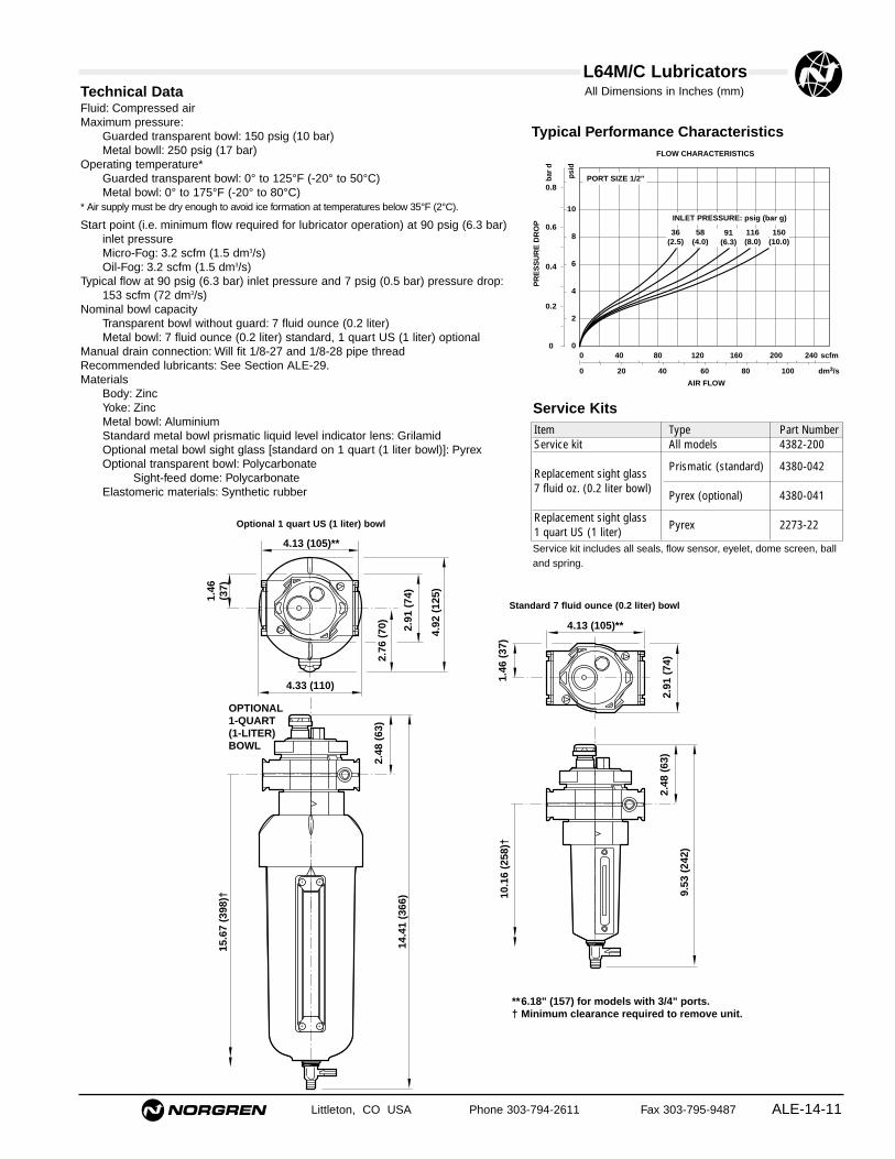
Littleton, CO USA Phone 303-794-2611 Fax 303-795-9487 ALE-14-11
Technical DataFluid: Compressed airMaximum pressure:
Guarded transparent bowl: 150 psig (10 bar)Metal bowll: 250 psig (17 bar)
Operating temperature*Guarded transparent bowl: 0° to 125°F (-20° to 50°C)Metal bowl: 0° to 175°F (-20° to 80°C)
* Air supply must be dry enough to avoid ice formation at temperatures below 35°F (2°C).
Start point (i.e. minimum flow required for lubricator operation) at 90 psig (6.3 bar)inlet pressureMicro-Fog: 3.2 scfm (1.5 dm3/s)Oil-Fog: 3.2 scfm (1.5 dm3/s)
Typical flow at 90 psig (6.3 bar) inlet pressure and 7 psig (0.5 bar) pressure drop:153 scfm (72 dm3/s)
Nominal bowl capacityTransparent bowl without guard: 7 fluid ounce (0.2 liter)Metal bowl: 7 fluid ounce (0.2 liter) standard, 1 quart US (1 liter) optional
Manual drain connection: Will fit 1/8-27 and 1/8-28 pipe threadRecommended lubricants: See Section ALE-29.Materials
Body: ZincYoke: ZincMetal bowl: AluminiumStandard metal bowl prismatic liquid level indicator lens: GrilamidOptional metal bowl sight glass [standard on 1 quart (1 liter bowl)]: PyrexOptional transparent bowl: Polycarbonate
Sight-feed dome: PolycarbonateElastomeric materials: Synthetic rubber
Typical Performance Characteristics
INLET PRESSURE: psig (bar g)
FLOW CHARACTERISTICS
0 20 40 60 80 100 dm3/s
AIR FLOW
0 40 80 120 160 200 240 scfm
PR
ES
SU
RE
DR
OP
0.8
0.6
0.4
0.2
0
bar
d
10
8
6
4
2
0
psi
d
PORT SIZE 1/2"
36(2.5)
58(4.0)
91(6.3)
116(8.0)
150(10.0)
9.53
(24
2)
10.1
6 (2
58)†
2.48
(63
)
4.13 (105)**
1.46
(37
)
2.91
(74
)
** 6.18" (157) for models with 3/4" ports.† Minimum clearance required to remove unit.
4.13 (105)**
4.33 (110)
2.76
(70
)
1.46
(37)
2.91
(74
)
4.92
(12
5)
2.48
(63
)
14.4
1 (3
66)
15.6
7 (3
98)†
OPTIONAL1-QUART(1-LITER)BOWL
Standard 7 fluid ounce (0.2 liter) bowl
Optional 1 quart US (1 liter) bowl
Service KitsItem Type Part NumberService kit All models 4382-200
Prismatic (standard) 4380-042Replacement sight glass7 fluid oz. (0.2 liter bowl)
Pyrex (optional) 4380-041
Replacement sight glassPyrex 2273-22
1 quart US (1 liter)Service kit includes all seals, flow sensor, eyelet, dome screen, balland spring.
All Dimensions in Inches (mm)
See Section ALE-25 for Accessories
ALE-14-12 Littleton, CO USA Phone 303-794-2611 Fax 303-795-9487
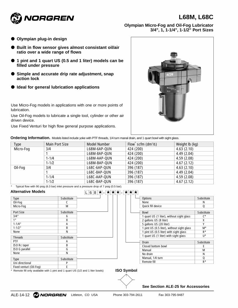
L68M, L68C
● Olympian plug-in design
● Built in flow sensor gives almost consistant oil/airratio over a wide range of flows
● 1 pint and 1 quart US (0.5 and 1 liter) models can befilled under pressure
● Simple and accurate drip rate adjustment, snapaction lock
● Ideal for general lubrication applications
Use Micro-Fog models in applications with one or more points oflubrication.
Use Oil-Fog models to lubricate a single tool, cylinder or other airdriven device.
Use Fixed Venturi for high flow general purpose applications.
Olympian Micro-Fog and Oil-Fog Lubricator3/4", 1, 1-1/4", 1-1/2" Port Sizes
Ordering Information. Models listed include yoke with PTF threads, 1/4 turn manal drain, and 1 quart bowl with sight glass.
Type Main Port Size Model Number Flow* scfm (dm3/s) Weight lb (kg)Micro-Fog 3/4 L68M-6AP-QUN 424 (200) 4.63 (2.10)
1 L68M-8AP-QUN 424 (200) 4.49 (2.04)1-1/4 L68M-AAP-QUN 424 (200) 4.59 (2.08)1-1/2 L68M-BAP-QUN 424 (200) 4.67 (2.12)
Oil-Fog 3/4 L68C-6AP-QUN 396 (187) 4.63 (2.10)1 L68C-8AP-QUN 396 (187) 4.49 (2.04)1-1/4 L68C-AAP-QUN 396 (187) 4.59 (2.08)1-1/2 L68C-BAP-QUN 396 (187) 4.67 (2.12)
* Typical flow with 90 psig (6.3 bar) inlet pressure and a pressure drop of 7 psig (0.5 bar).
Alternative Models L 6 8 -★ ★ ★ - ★★ ★ ★
Type SubstituteOil-Fog CMicro-Fog M
Threads SubstitutePTF AISO Rc taper BISO G parallel GNone N
Type SubstituteUni directional PFixed venturi (Oil-Fog) E
Port Size Substitute3/4" 61" 81-1/4" A1-1/2" BNone N
Options SubstituteNone NQuick fill device Q
Drain SubstituteClosed bottom bowl EManual MNo drain NManual, 1/4 turn QRemote fill R*
Bowl Substitute1 quart US (1 liter), without sight glass C*2 gallons US (8 liter) X5 gallons US (20 liter) Y1 pint US (0.5 liter), without sight glass M*1 pint US (0.5 liter) with sight glass R*1 quart US (1 liter) with sight glass U*
* Remote fill only available with 1 pint and 1 quart US (1/2 and 1 liter bowls) ISO Symbol
7.81 (198) 2 gal11.81 (300) 5 gal
21.2
(53
8) 2
gal
Res
ervo
ir24
.2 (
614)
5 g
al R
eser
voir
2 and 5 Gallon(8 and 20 liter)
Reservoirs
2.91
(74)7.48 (190)**
Front ViewTop View
7.18
(18
2) 2
gal
11.1
8 (2
84)
5 g
al
L68M/C Lubricators
ALE-14-13
All Dimensions in Inches (mm)
Littleton, CO USA Phone 303-794-2611 Fax 303-795-9487
INLET PRESSURE: psig (bar)
FLOW CHARACTERISTICS
0 40 80 120 160 200 dm3/sAIR FLOW
0 80 160 240 320 400 480 scfm
0.8
0.6
0.4
0.2
0
PR
ES
SU
RE
DR
OP
bar
d
10
8
6
4
2
0
psi
d
PORT SIZE: 1"MICRO-FOG
36(2.5)
58(4.0)
91(6.3)
116(8.0)
150(10.0)
INLET PRESSURE: psig (bar)
FLOW CHARACTERISTICS
0 100 200 300 400 500 dm3/sAIR FLOW
0 200 400 600 800 1 000 scfm
0.8
0.6
0.4
0.2
0
PR
ES
SU
RE
DR
OP
bar
d
10
8
6
4
2
0
psi
d
FIXED VENTURIPORT SIZE 1 1/2"
36(2.5)
58(4.0)
91(6.3)
116(8.0)
150(10.0)
INLET PRESSURE: psig (bar)
FLOW CHARACTERISTICS
0 40 80 120 160 200 dm3/sAIR FLOW
0 80 160 240 320 400 480 scfm
0.8
0.6
0.4
0.2
0P
RE
SS
UR
E D
RO
P
bar
d
10
8
6
4
2
0
psi
d
PORT SIZE: 1"OIL-FOG
36(2.5)
58(4.0)
91(6.3)
116(8.0)
150(10.0)
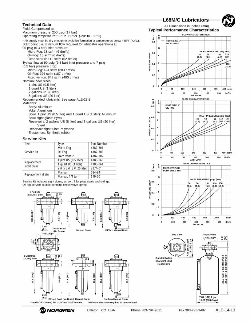
Typical Performance CharacteristicsTechnical DataFluid: Compressed airMaximum pressure: 250 psig (17 bar)Operating temperature*: 0° to +175°F (-20° to +80°C)* Air supply must be dry enough to avoid ice formation at temperatures below +35°F (+2°C).Start point (i.e. minimum flow required for lubricator operation) at 90 psig (6.3 bar) inlet pressure:
Micro-Fog: 13 scfm (6 dm3/s)Oil-Fog: 13 scfm (6 dm3/s) Fixed venturi: 110 scfm (52 dm3/s)
Typical flow at 90 psig (6.3 bar) inlet pressure and 7 psig (0.5 bar) pressure drop:
Micro-Fog: 424 scfm (200 dm3/s)Oil-Fog: 396 scfm (187 dm3/s)Fixed venturi: 848 scfm (400 dm3/s)
Nominal bowl sizes:1 pint US (0.5 liter)1 quart US (1 liter)2 gallons US (8 liter)5 gallons US (20 liter)
Recommended lubricants: See page ALE-29-2Materials:
Body: AluminumYoke: AluminumBowl, 1 pint US (0.5 liter) and 1 quart US (1 liter): AluminumBowl sight glass: PyrexReservoirs, 2 gallons US (8 liter) and 5 gallons US (20 liter):
SteelReservoir sight tube: PolytheneElastomers: Synthetic rubber
1 Pint US (0.5 Liter) Bowl
1/4 Turn Manual Drain
8.2
(208
)
14.2
(36
1)†
Closed Bowl (No Drain)
7.5
(190
)2.
91(7
4)
2.40(61) .
13.5
(34
3)†
Manual Drain
7.8
(197
)
13.8
(35
0)†
7.48 (190)**
2.13
(54)
** Add 0.39" (10 mm) for 1-1/4" and 1-1/2"models. † Minimum clearance required to remove bowl.
1 Quart US (1 Liter) Bowl
1/4 Turn Manual Drain
10.6
(26
9)
18.2
(46
3)†
Manual Drain
10.2
(25
8)
17.8
(45
2)†
Closed Bowl (No Drain)
9.9
(251
)
17.5
(44
5)†
2.40(61) .
2.91
(74)
Service KitsItem Type Part Number
Micro-Fog 4382-301Service kit Oil-Fog 4382-300
Fixed venturi 4382-302
Replacement1 pint US (0.5 liter) 4380-060
sight glass1 quart US (1 liter) 4380-0612 & 5 gal (8 & 20 liter) 2274-01
Replacement drainManual 684-84Manual, 1/4 turn 619-50
Service kit includes sight dome, screen, filler plug, seals and o-rings.Oil fog service kit also contains check valve spring.
See Section ALE-25 for Accessories
Littleton, CO USA Phone 303-794-2611 Fax 303-795-9487
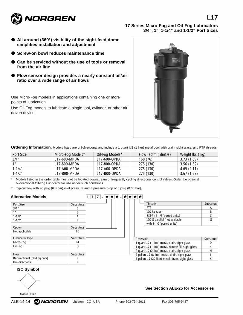
L17
● All around (360°) visibility of the sight-feed domesimplifies installation and adjustment
● Screw-on bowl reduces maintenance time
● Can be serviced without the use of tools or removalfrom the air line
● Flow sensor design provides a nearly constant oil/airratio over a wide range of air flows
Use Micro-Fog models in applications containing one or morepoints of lubrication
Use Oil-Fog models to lubricate a single tool, cylinder, or other airdriven device
17 Series Micro-Fog and Oil-Fog Lubricators3/4", 1", 1-1/4" and 1-1/2" Port Sizes
ALE-14-14
ISO Symbol
Manual drain
Alternative Models - ★★★ ★★ ★ -1 ★L 7
Threads SubstitutePTF AISO Rc taper BBSPP (1-1/2" ported units) CISO G parallel (not available Gwith 1-1/2" ported units)
Reservoir Substitute1 quart US (1 liter) metal, drain, sight glass D1 quart US (1 liter) metal, remote fill, sight glass 42 quart US (2 liter) metal, drain, sight glass H2 gallon US (8 liter) metal, drain, sight glass J5 gallon US (20 liter) metal, drain, sight glass K
Lubricator Type SubstituteMicro-Fog MOil-Fog O
Port Size Substitute3/4" 61" 81-1/4" A1-1/2" B
Flow SubstituteBi-directional (Oil-Fog only) EUni-directional P
Option SubstituteNot applicable 00
Ordering Information. Models listed are uni-directional and include a 1 quart US (1 liter) metal bowl with drain, sight glass, and PTF threads.
Port Size Micro-Fog Models* Oil-Fog Models* Flow† scfm ( dm3/s) Weight lbs ( kg)3/4" L17-600-MPDA L17-600-OPDA 160 (76) 3.73 (1.69)1" L17-800-MPDA L17-800-OPDA 275 (130) 3.56 (1.62)1-1/4" L17-A00-MPDA L17-A00-OPDA 275 (130) 4.65 (2.11)1-1/2" L17-B00-MPDA L17-B00-OPDA 275 (130) 3.67 (1.67)
* Models listed in the order table must not be located downstream of frequently cycling directional control valves. Order the optional bi-directional Oil-Fog Lubricator for use under such conditions.
† Typical flow with 90 psig (6.3 bar) inlet pressure and a pressure drop of 5 psig (0.35 bar).
L17 Lubricators
Littleton, CO USA Phone 303-794-2611 Fax 303-795-9487 ALE-14-15
All Dimensions in Inches (mm)
Technical DataFluid: Compressed airMaximum pressure: 250 psig (17 bar)Operating temperature*: 0° to 175°F (-20° to 80°C)* Air supply must be dry enough to avoid ice formation at temperatures below 35°F (2°C).Start point (minimum flow required for lubricator operation): 8 scfm (3.8 dm3/s) at
90 psig (6.3 bar) inlet pressureTypical flow with 90 psig (6.3 bar) inlet pressure and 5 psig (0.35 bar) pressure
drop:1" ports: 275 scfm (130 dm3/s)
Nominal reservoir sizeStandard: 1 quart US (1 liter)Optional: 2 quart US (2 liter)
2 gallon US (8 liter)5 gallon US (20 liter)
Manual drain connection on 1 quart reservoir: Will fit 1/8-27 and 1/8-28 pipe threadRecommended lubricants: See Section ALE-29.Materials
Body: AluminumReservoir:
1 quart US (1 liter): Aluminum2 quart US (2 liter) and larger: Steel**
Reservoir sight glass: PyrexSight-feed dome
Standard: Transparent nylonOptional: Pyrex and aluminum
Elastomers: Neoprene and nitrile** The 2 and 5 gallon (8 and 20 liter) steel reservoirs are ASME rated according to
the ASME Pressure Vessel Code, Section VIII
Typical Performance Characteristics
PR
ES
SU
RE
DR
OP 0.3
0.2
0.1
0
bar
d
5
4
3
2
1
0
psi
d
0 40 80 120 160 200 dm3/s
AIR FLOW
0 80 160 240 320 400 scfm
36 (2.5 ) 58 (4.0) 90 (6.3) 116 (8.0)INLET PRESSURE:psig (bar g)
150(10.0)
180(12.5)
PORT SIZE: 1"
4.50 (114)
L17 Micro-Fog
2.40(61)
10.4
(26
5) w
ith
dra
in
4.32
(11
0)2.
03†
(52)
16.9
(42
9)††
10.0
(25
4) w
ith
ou
t d
rain
B
C
A
L17 Oil-Fog Micro-Fog shown,Typical of Oil Fog
1 quart US (1 liter) reservoir1/4 turn drain 2 quart US (2 liter) reservoir
2 gallon US (8 liter) reservoir5 gallon US (20 liter) reservoir
Reservoir A B ∅ C2 quart US (2 liter) 13.1 ( 333) 4.63 (118) 5.38 (137)2 gallon US (8 liter) 21.2 (538) 6.25 (159) 7.44 (189)5 gallon US (20 liter) 24.2 (614) 10.3 (260) 11.4 (291)† Standard dome: 2.03" (52 mm)
Pyrex dome: 2.72" (69 mm)
†† Minimum clearance required to remove bowl.
Service kit 5771-02 includes o-rings, seals and gaskets.
Reservoir sight glass kits, include all o-rings, seals, glass,guard, and sight glass hardware.
Service KitsItem Type Part NumberService kit Oil-Fog and Micro-Fog 5771-02
Reservoir sight glass kit1 quart US (1 liter) 2273-222 quart US (2 liter) 2273-042/5 gallon US (8/20 liter) 2274-01
Replacement drain 1/4 Turn 619-50
See Section ALE-25 for Accessories
Littleton, CO USA Phone 303-794-2611 Fax 303-795-9487ALE-14-16
10-028
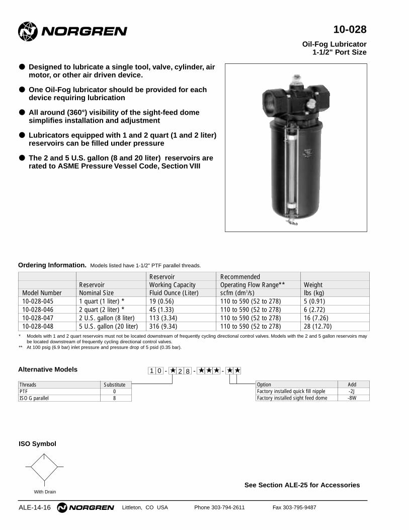
● Designed to lubricate a single tool, valve, cylinder, airmotor, or other air driven device.
● One Oil-Fog lubricator should be provided for eachdevice requiring lubrication
● All around (360°) visibility of the sight-feed domesimplifies installation and adjustment
● Lubricators equipped with 1 and 2 quart (1 and 2 liter)reservoirs can be filled under pressure
● The 2 and 5 U.S. gallon (8 and 20 liter) reservoirs arerated to ASME Pressure Vessel Code, Section VIII
Oil-Fog Lubricator1-1/2" Port Size
ISO Symbol
With Drain
* Models with 1 and 2 quart reservoirs must not be located downstream of frequently cycling directional control valves. Models with the 2 and 5 gallon reservoirs maybe located downstream of frequently cycling directional control valves.
** At 100 psig (6.9 bar) inlet pressure and pressure drop of 5 psid (0.35 bar).
Reservoir RecommendedReservoir Working Capacity Operating Flow Range** Weight
Model Number Nominal Size Fluid Ounce (Liter) scfm (dm3/s) lbs (kg)10-028-045 1 quart (1 liter) * 19 (0.56) 110 to 590 (52 to 278) 5 (0.91)10-028-046 2 quart (2 liter) * 45 (1.33) 110 to 590 (52 to 278) 6 (2.72)10-028-047 2 U.S. gallon (8 liter) 113 (3.34) 110 to 590 (52 to 278) 16 (7.26)10-028-048 5 U.S. gallon (20 liter) 316 (9.34) 110 to 590 (52 to 278) 28 (12.70)
Ordering Information. Models listed have 1-1/2" PTF parallel threads.
Alternative Models 2★- ★ ★★ ★8 - -01
Option AddFactory installed quick fill nipple -2JFactory installed sight feed dome -8W
★
Threads SubstitutePTF 0ISO G parallel 8
10-028 Lubricators
ALE-14-17
All Dimensions in Inches (mm)
Littleton, CO USA Phone 303-794-2611 Fax 303-795-9487
Technical DataFluid: Compressed airMaximum pressure: 250 psig (17 bar)Operating temperature*: 0° to 175°F (-20° to 80°C)* Air supply must be dry enough to avoid ice formation at temperatures below 35°F (2°C).Start point (minimum flow required for lubricator operation) at 90 psig (6.3 bar)
inlet pressure: 103 scfm (49 dm3/s) Typical flow at 90 psig (6.3 bar) inlet pressure and 5 psig (0.35 bar) pressure drop:
568 scfm (268 dm3/s)Nominal reservoir sizes:
1 quart (1 liter)2 quart (2 liter)2 U.S. gallon (8 liter)5 U.S. gallon (20 liter)
Recommended lubricants: See Section ALE-29.Materials
Body: AluminumReservoir: Steel Reservoir liquid level indicator lens: PyrexSight-feed dome
Standard: Transparent nylonOptional: Pyrex and aluminum
Elastomers: Neoprene and Nitrile
12
8
4
0
INL
ET
PR
ES
SU
RE
bar
200
160
120
80
40
0
psi
g
0 100 200 300 400 500 dm3/sAIR FLOW
0 200 400 600 800 1000 scfm
OPERATING RANGE
A B
A: Minimum flow based on oil drip rate of 5 drops per minute.B: Maximum flow based on pressure drop of 5 psid (0.35 bar).
Oil: SAE 10Oil Feed Setting: Maximum
Typical Performance Characteristics
Reservoir A B C D1 quart (1 liter) 4.72 (120) 4.06 (103) 8.27 (210) 15 (376)2 quart (2 liter) 5.28 (134) 4.63 (118) 10.52 (267) 19 (477)2 gallon (8 liter) 7.81 (198) 7.18 (182) 18.34 (466) 32 (813)5 gallon (20 liter) 11.81 (300) 11.18 (284) 21.59 (548) 37 (940)
C
5.25 (133)
2.19
(56)
1 and 2 quart (1 and 2 liter) reservoir 2 and 5 gallon (8 and 20 liter) reservoir
** Optional pyrex sight-feed dome.† Minimum clearance required to remove bowl.
5.25 (133)
2.19
(56)
CD †
D †
B A
A
B
3.03
(7
7)**
3.03
(7
7)**
Liquid level lens kit include sight glass, sight glass guards, seals,and hardware.
Service KitsItem Type Part Number
1 quart reservoir 2272-02Liquid level lens kit 2 quart reservoir 2273-04
2 and 5 gallon reservoir 2274-01Replacement drain Manual petcock 684-01
See Section ALE-25 for Accessories
ALE-14-18 Littleton, CO USA Phone 303-794-2611 Fax 303-795-9487
10-076
● Designed to lubricate a single tool, valve, cylinder, airmotor, or other air driven device
● One Oil-Fog lubricator should be provided for eachdevice requiring lubrication
● All around (360°) visibility of the sight-feed domesimplifies installation and adjustment
● The 2 and 5 U.S. gallon (8 and 20 liter) reservoirs arerated to ASME Pressure Vessel Code, Section VIII
Oil-Fog Lubricator2" Port Size
ISO Symbol
With Drain
* At 100 psig (6.9 bar) inlet pressure and pressure drop of 5 psid (0.35 bar).
Reservoir RecommendedReservoir Working Capacity Operating Flow Range* Weight
Model Number Nominal Size Fluid Ounce (Liter) scfm (dm3/s) lbs (kg)10-076-004 2 U.S. gallon (8 liter) 113 (3.34) 250 to 1000 (118 to 472) 19 (8.6)10-076-005 5 U.S. gallon (20 liter) 316 (9.34) 250 to 1000 (118 to 472) 32 (14.5)
Ordering Information. Models listed have 2" PTF threads.
Alternative Models7★- ★ ★★ ★6 - -01
Option AddFactory installed pyrex sight feed dome 8W
★
Threads SubstitutePTF 0ISO G parallel 8
10-076 Lubricators
ALE-14-19
All Dimensions in Inches (mm)
Littleton, CO USA Phone 303-794-2611 Fax 303-795-9487
Technical DataFluid: Compressed airMaximum pressure: 250 psig (17 bar)Operating temperature*: 0° to 175°F (-20° to 80°C)* Air supply must be dry enough to avoid ice formation at temperatures below 35°F (2°C).Start point (minimum flow required for lubricator operation) at 90 psig (6.3 bar)
inlet pressure: 240 scfm (123 dm3/s)Typical flow with 90 psig (6.3 bar) inlet pressure and 5 psig (0.35 bar) pressure
drop: 1300 scfm (614 dm3/s)Nominal reservoir sizes:
2 U.S. gallon (8 liter)5 U.S. gallon (20 liter)
Recommended lubricants: See Section ALE-29.Materials
Body and adapter: AluminumReservoir: Steel Reservoir liquid level indicator lens: PyrexSight-feed dome
Standard: Transparent nylonOptional: Pyrex and aluminum
Elastomers: Nitrile
16
12
8
4
0
INL
ET
PR
ES
SU
RE
bar
240
200
160
120
80
40
0
psi
g
0 200 400 600 800 1000 dm3/s
AIR FLOW
0 400 800 1200 1600 2000 scfm
OPERATING RANGE
A B
A: Minimum flow based on oil drip rate of 5 drops per minute.B: Maximum flow based on pressure drop of 5 psid (0.35 bar).
Oil: SAE 10Oil Feed Setting: Maximum
Typical Performance Characteristics
Reservoir A B C D2 gallon (8 liter) 7.81 (198) 7.18 (182) 21.53 (547) 35 (887)5 gallon (20 liter) 11.81 (300) 11.18 (284) 24.78 (629) 40 (1014)
C
5.13 (130)
2.31
(59)
2 and 5 gallon (8 and 20 liter) reservoir
** Optional pyrex sight-feed dome.† Minimum clearance required to remove bowl.
D †
A
B
3.15
(8
0)**
Reservoir sight glass kits include sight glass, sight glass guards,seals, and hardware.
Service KitsItem Type Part NumberLiquid level lens kit 8 and 20 liter reservoir 2274-01Replacement drain Manual petcock 684-01
See Section ALE-25 for Accessories
ALE-14-20 Littleton, CO USA Phone 303-794-2611 Fax 303-795-9487
10-015, 10-065
● Provides centralized air-borne lubrication formachine bearings, gears, chains, slides, ways, etc
● Controls can be installed to start-up and shut-downthe lubricator with the machine
● Delivers a fog of oil to the application points, coatingbearing surfaces with a thin oil film and reducing oilconsumption
● Air carrying the lubricants passes through thebearing housing, reducing bearing temperature andcontamination, providing longer bearing life
● The 2 and 5 U.S. gallon (8 and 20 liter) reservoirs arerated to ASME Pressure Vessel Code, Section VIII
● Refer to Norgren Publication NT-1 for system design,bearing-inch ratings, and reclassifier selection
Micro-Fog® Machine Bearing Lubricator8 to 32 Bearing Inch Ratings 1/4" Port Size
ISO Symbol
With Drain
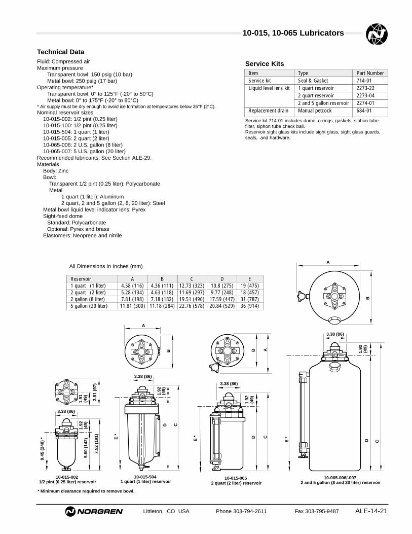
Model Number Reservoir - Nominal Size Reservoir - Working Capacity Weight lbs (kg)10-015-100 * 1/2 pint (0.25 liter) — 2 (0.91)10-015-002 1/2 pint (0.25 liter) 5 fluid ounce (0.15 liter) 2 (0.91)10-015-504 1 quart (1 liter) 19 fluid ounce (0.56 liter) 4.0 (1.8)10-015-005 2 quart (2 liter) 45 fluid ounce (1.33 liter) 6 (2.72)10-065-006 2 U.S. gallon (8 liter) 113 fluid ounce (3.34 liter) 15.4 (7.0)10-065-007 5 U.S. gallon (20 liter) 316 fluid ounce (9.34 liter) 28 (12.7)
Ordering Information. Models listed have 1/4" PTF threads and are rated from 8 to 32 bearing inches.
* Equipped with factory installed remote fill device.
Alternative Models
★0- ★ ★★ ★★ - -01Option AddWall bracket attached to 10-015 -1BmodelsQuick fill -2HPyrex sight feed dome -7CLow oil level switch with 10-015-504 -3ALow oil level switch with 10-015-005 -3ALow oil level switch with 10-065-006 -3DLow oil level switch with 10-065-007 -3EBowl guard for 0.5 pint reservoir -2U
★
10-015, 10-065 Lubricators
ALE-14-21
All Dimensions in Inches (mm)
Littleton, CO USA Phone 303-794-2611 Fax 303-795-9487
Technical DataFluid: Compressed airMaximum pressure
Transparent bowl: 150 psig (10 bar)Metal bowl: 250 psig (17 bar)
Operating temperature*Transparent bowl: 0° to 125°F (-20° to 50°C)Metal bowl: 0° to 175°F (-20° to 80°C)
* Air supply must be dry enough to avoid ice formation at temperatures below 35°F (2°C).Nominal reservoir sizes
10-015-002: 1/2 pint (0.25 liter)10-015-100: 1/2 pint (0.25 liter)10-015-504: 1 quart (1 liter)10-015-005: 2 quart (2 liter)10-065-006: 2 U.S. gallon (8 liter)10-065-007: 5 U.S. gallon (20 liter)
Recommended lubricants: See Section ALE-29.Materials
Body: ZincBowl:
Transparent 1/2 pint (0.25 liter): PolycarbonateMetal
1 quart (1 liter): Aluminum2 quart, 2 and 5 gallon (2, 8, 20 liter): Steel
Metal bowl liquid level indicator lens: PyrexSight-feed dome
Standard: PolycarbonateOptional: Pyrex and brass
Elastomers: Neoprene and nitrile
3.38 (86)
3.81
(97
)
1.92
(49)
7.52
(19
1)
1.91
(49)
9.45
(24
0) *
5.60
(14
2)
10-015-002 1/2 pint (0.25 liter) reservoir
* Minimum clearance required to remove bowl.
C
A
DB
3.38 (86)
1.92
(49)
10-065-006/-007 2 and 5 gallon (8 and 20 liter) reservoir
E *
10-015-504 1 quart (1 liter) reservoir
E *
3.38 (86)
1.92
(49)
D C
B
A
10-015-005 2 quart (2 liter) reservoir
B A
3.38 (86)
1.92
(49)
D C
E *
Reservoir A B C D E1 quart (1 liter) 4.58 (116) 4.36 (111) 12.73 (323) 10.8 (275) 19 (475)2 quart (2 liter) 5.28 (134) 4.63 (118) 11.69 (297) 9.77 (248) 18 (457)2 gallon (8 liter) 7.81 (198) 7.18 (182) 19.51 (496) 17.59 (447) 31 (787)5 gallon (20 liter) 11.81 (300) 11.18 (284) 22.76 (578) 20.84 (529) 36 (914)
Service kit 714-01 includes dome, o-rings, gaskets, siphon tubefilter, siphon tube check ball.Reservoir sight glass kits include sight glass, sight glass guards,seals, and hardware.
Service KitsItem Type Part NumberService kit Seal & Gasket 714-01Liquid level lens kit 1 quart reservoir 2273-22
2 quart reservoir 2273-042 and 5 gallon reservoir 2274-01
Replacement drain Manual petcock 684-01
10-015, 10-065 Lubricators
Littleton, CO USA Phone 303-794-2611 Fax 303-795-9487ALE-14-22
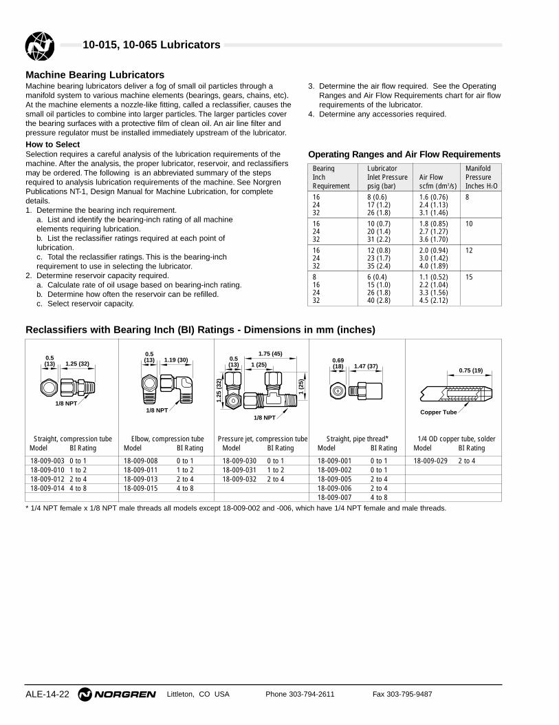
Machine Bearing LubricatorsMachine bearing lubricators deliver a fog of small oil particles through amanifold system to various machine elements (bearings, gears, chains, etc).At the machine elements a nozzle-like fitting, called a reclassifier, causes thesmall oil particles to combine into larger particles. The larger particles coverthe bearing surfaces with a protective film of clean oil. An air line filter andpressure regulator must be installed immediately upstream of the lubricator.
How to SelectSelection requires a careful analysis of the lubrication requirements of themachine. After the analysis, the proper lubricator, reservoir, and reclassifiersmay be ordered. The following is an abbreviated summary of the stepsrequired to analysis lubrication requirements of the machine. See NorgrenPublications NT-1, Design Manual for Machine Lubrication, for completedetails.1. Determine the bearing inch requirement.
a. List and identify the bearing-inch rating of all machine elements requiring lubrication.b. List the reclassifier ratings required at each point of lubrication.c. Total the reclassifier ratings. This is the bearing-inch requirement to use in selecting the lubricator.
2. Determine reservoir capacity required.a. Calculate rate of oil usage based on bearing-inch rating.b. Determine how often the reservoir can be refilled.c. Select reservoir capacity.
3. Determine the air flow required. See the OperatingRanges and Air Flow Requirements chart for air flowrequirements of the lubricator.
4. Determine any accessories required.
Straight, compression tube Elbow, compression tube Pressure jet, compression tube Straight, pipe thread* 1/4 OD copper tube, solderModel BI Rating Model BI Rating Model BI Rating Model BI Rating Model BI Rating
18-009-003 0 to 1 18-009-008 0 to 1 18-009-030 0 to 1 18-009-001 0 to 1 18-009-029 2 to 418-009-010 1 to 2 18-009-011 1 to 2 18-009-031 1 to 2 18-009-002 0 to 118-009-012 2 to 4 18-009-013 2 to 4 18-009-032 2 to 4 18-009-005 2 to 418-009-014 4 to 8 18-009-015 4 to 8 18-009-006 2 to 4
18-009-007 4 to 8
Reclassifiers with Bearing Inch (BI) Ratings - Dimensions in mm (inches)
0.5 (13) 1.25 (32)
1/8 NPT
0.5 (13) 1.19 (30)
1/8 NPT
0.5 (13)
1.75 (45)
1 (25)
1 (2
5)
1/8 NPT
1.25
(32
)
0.69(18) 1.47 (37)
0.75 (19)
Copper Tube
* 1/4 NPT female x 1/8 NPT male threads all models except 18-009-002 and -006, which have 1/4 NPT female and male threads.
Operating Ranges and Air Flow RequirementsBearing Lubricator ManifoldInch Inlet Pressure Air Flow PressureRequirement psig (bar) scfm (dm3/s) Inches H2O16 8 (0.6) 1.6 (0.76) 824 17 (1.2) 2.4 (1.13)32 26 (1.8) 3.1 (1.46)16 10 (0.7) 1.8 (0.85) 1024 20 (1.4) 2.7 (1.27)32 31 (2.2) 3.6 (1.70)16 12 (0.8) 2.0 (0.94) 1224 23 (1.7) 3.0 (1.42)32 35 (2.4) 4.0 (1.89)8 6 (0.4) 1.1 (0.52) 1516 15 (1.0) 2.2 (1.04)24 26 (1.8) 3.3 (1.56)32 40 (2.8) 4.5 (2.12)