ltspicegettingstartedguide.pdf
TRANSCRIPT
LTspice IV Getting Started GuideLTspice IV Getting Started Guide
Copyright © 2011 Linear Technology. All rights reserved.

2
Benefits of Using LTspice IVBenefits of Using LTspice IV Stable SPICE circuit simulation with
Unlimited number of nodes
Outperforms pay-for options
Unlimited number of nodesSchematic/symbol editorWaveform viewer
LTspice is also a great schematic capture
Library of passive devices Fast simulation of switching mode power supplies (SMPS)
Steady state detectionSteady state detectionTurn on transientStep response
Over 1100 macromodels ofLinear Technology products500+ SMPS p p
Efficiency / power computationsAdvanced analysis and simulation options
© 2011 Linear Technology
Not covered in this presentation
3
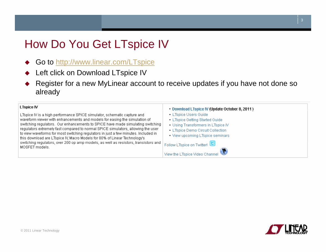
How Do You Get LTspice IVHow Do You Get LTspice IV Go to http://www.linear.com/LTspiceLeft click on Download LTspice IV Register for a new MyLinear account to receive updates if you have not done so already
© 2011 Linear Technology

Getting Started
Copyright © 2011 Linear Technology. All rights reserved.
5
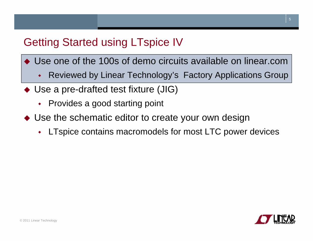
Getting Started using LTspice IVGetting Started using LTspice IVUse one of the 100s of demo circuits available on linear.com
Reviewed by Linear Technology’s Factory Applications GroupReviewed by Linear Technology s Factory Applications Group
Use a pre-drafted test fixture (JIG)Provides a good starting pointProvides a good starting point
Use the schematic editor to create your own designLTspice contains macromodels for most LTC power devicesp p
© 2011 Linear Technology

6
Demo Circuits on linear comDemo Circuits on linear.comGo to http://www.linear.com Enter root part number in the search te oot pa t u be t e sea cbox (e.g. 3411)Select Simulate Tab on the left side Follo the instr ctions pro idedFollow the instructions provided
If you do not find a demo circuit of interest, use a pre-drafted test
Download LTspice
, pfixture – covered next
Download LTspice
Download Demo Circuit
C l li f d i i il bl
© 2011 Linear Technology
Complete list of demo circuits available at www.linear.com/democircuits
7
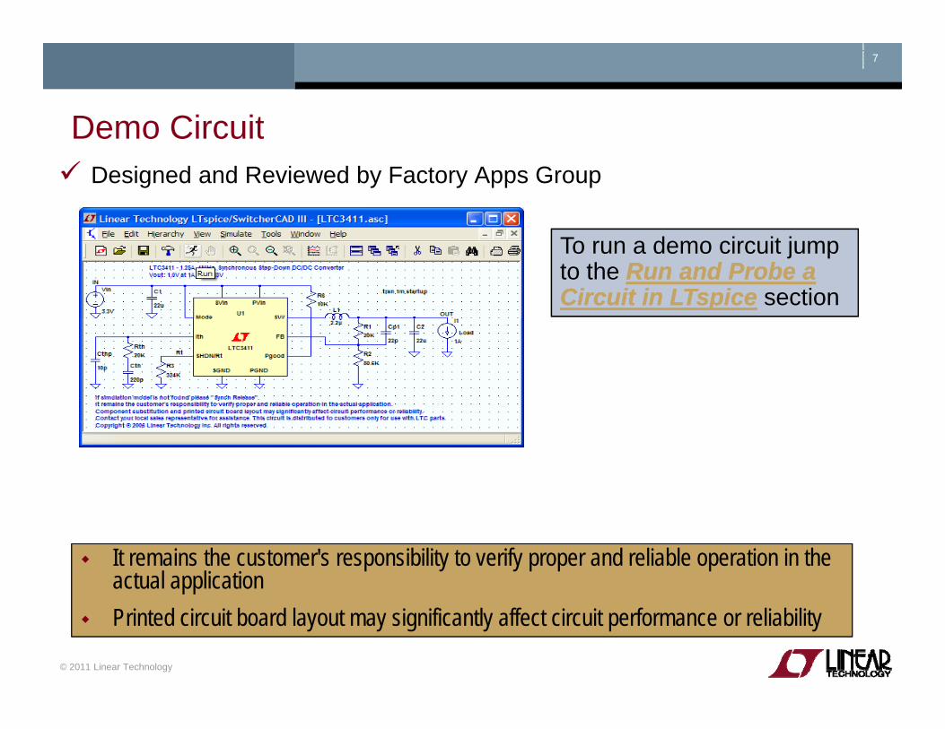
Demo CircuitDemo CircuitDesigned and Reviewed by Factory Apps Group
To run a demo circuit jump to the Run and Probe a Run and Probe a Circuit in LTspiceCircuit in LTspice section
What if I cannot find a demo circuit?a demo circuit?
It remains the customer's responsibility to verify proper and reliable operation in the actual application
© 2011 Linear Technology
Printed circuit board layout may significantly affect circuit performance or reliability

8
Getting Started using LTspice IVGetting Started using LTspice IVUse one of the 100s of demo circuits available on linear.com
Reviewed by Linear Technology’s Factory Applications GroupReviewed by Linear Technology s Factory Applications Group
Use a pre-drafted test fixture (JIG)Provides a good starting pointProvides a good starting point
Use the schematic editor to create your own designLTspice contains macromodels for most LTC power devicesp p
© 2011 Linear Technology
9
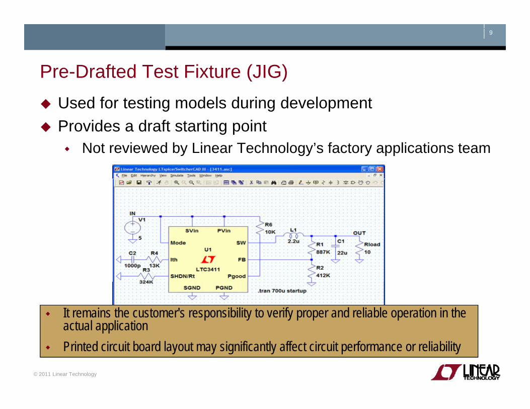
Pre-Drafted Test Fixture (JIG)Pre Drafted Test Fixture (JIG)Used for testing models during developmentProvides a draft starting pointProvides a draft starting point
Not reviewed by Linear Technology’s factory applications team
It remains the customer's responsibility to verify proper and reliable operation in the actual application
© 2011 Linear Technology
Printed circuit board layout may significantly affect circuit performance or reliability
10
Start with a New SchematicNew Schematic
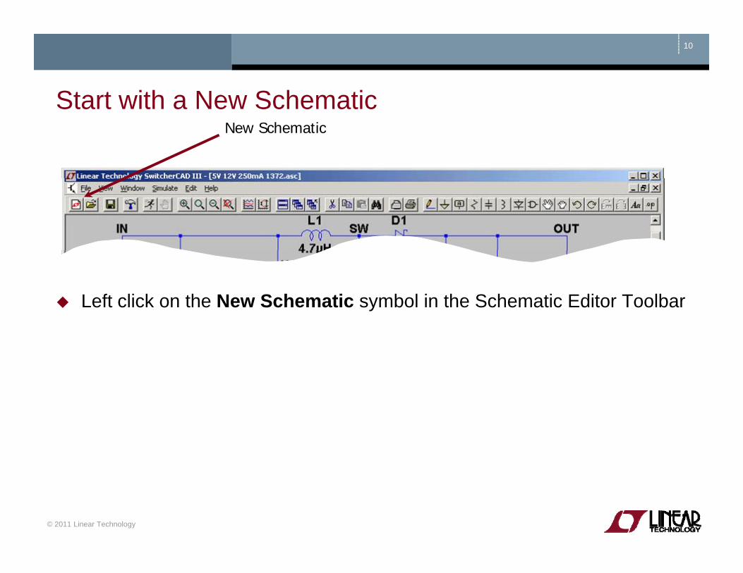
Start with a New Schematic
Left click on the New Schematic symbol in the Schematic Editor Toolbar
© 2011 Linear Technology

11
Add a Macromodel & Opening Test FixtureAdd a Macromodel & Opening Test FixtureAdd Component
Left click on the Component symbol in the Schematic Editor ToolbarE t “ t” t t h f th d lEnter “root” part to search for the model (e.g. 3411)Left click on Open this macromodel’s test fixturetest fixture
To run a test fixture, jump to the Run and Run and Probe a Circuit in LTspiceProbe a Circuit in LTspice section
© 2011 Linear Technology
pp

12
Getting Started using LTspice IVGetting Started using LTspice IVUse one of the 100s of demo circuits available on linear.com
Reviewed by Linear Technology’s Factory Applications GroupReviewed by Linear Technology s Factory Applications Group
Use a pre-drafted test fixture (JIG)Provides a good starting pointProvides a good starting point
Use the schematic editor to create your own designLTspice contains macromodels for most LTC power devicesp p
© 2011 Linear Technology

Draft a Design Using the Schematic Editor
Copyright © 2011 Linear Technology. All rights reserved.
14
Start with a New SchematicNew Schematic
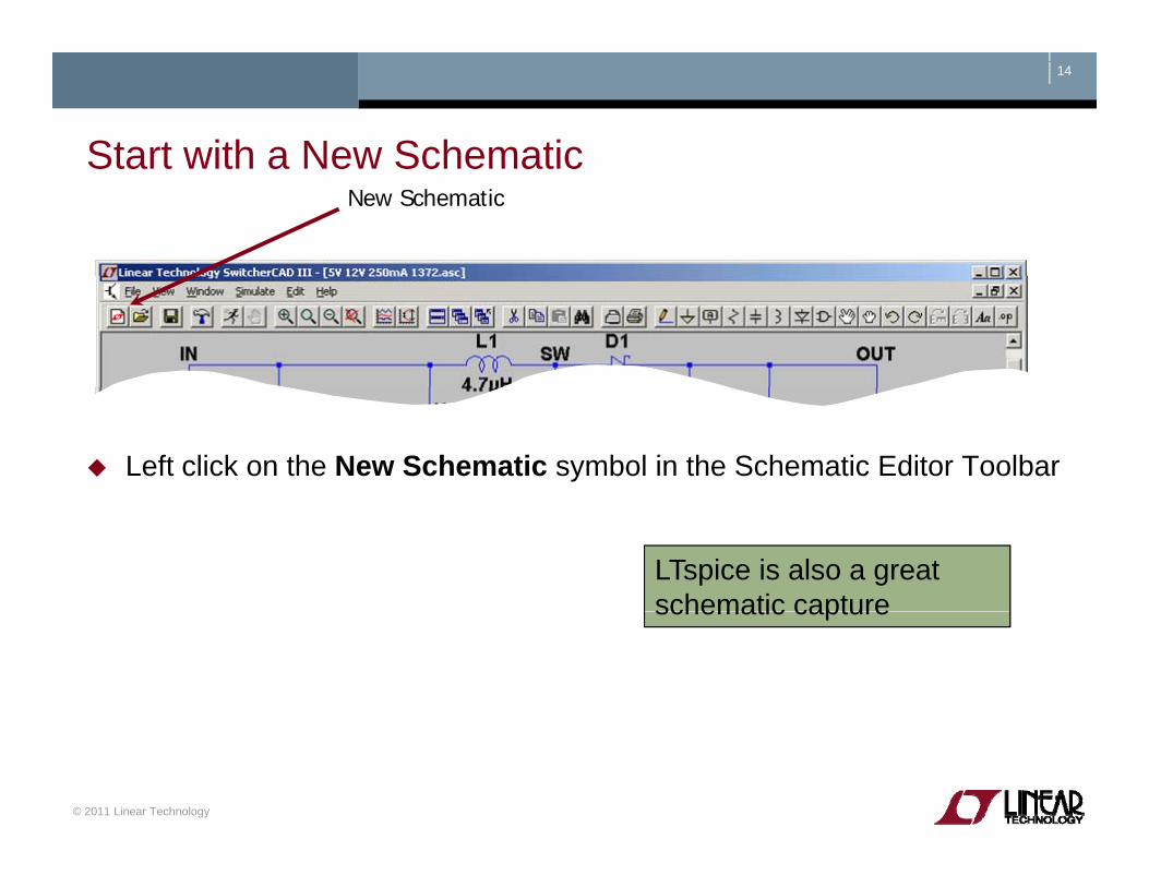
Start with a New Schematic
Left click on the New Schematic symbol in the Schematic Editor Toolbar
LTspice is also a great schematic captureschematic capture
© 2011 Linear Technology

15
Add a Linear Technology MacromodelAdd a Linear Technology MacromodelAdd Component
Left click on the Component symbol in the Schematic Editor ToolbarEnter “root” part to search for the model (e.g. 3411)Left click on OK
© 2011 Linear Technology

16
Getting the Latest DatasheetGetting the Latest DatasheetUse the macromodel’s shortcuts to download the Datasheetas a reference for your designy g
Hold Ctrl key and right click (Ctrl – right click) over the LT macromodel’s symbolLeft click on Go to Linear website for datasheet on the dialogLeft click on Go to Linear website for datasheet on the dialog box that appears
You can also open the macromodel's test fixture as a draft starting pointYou can also open the macromodel s test fixture as a draft starting point
© 2011 Linear Technology
17
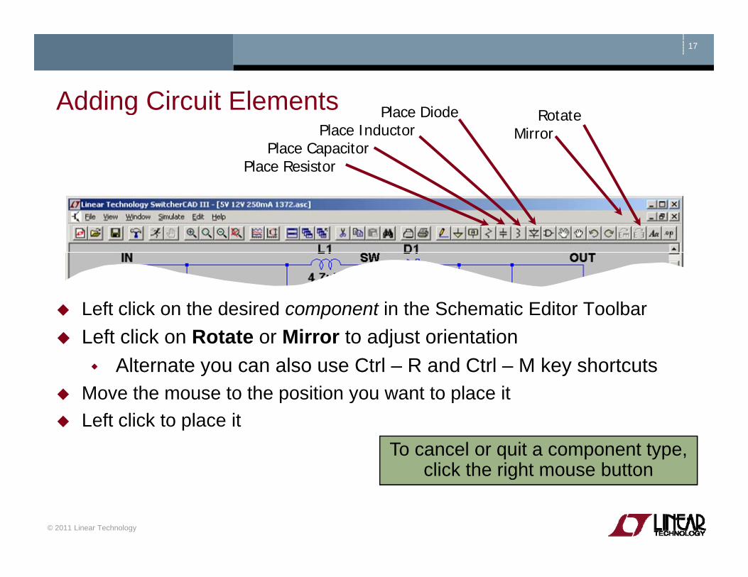
Adding Circuit Elements Pl Di dAdding Circuit ElementsRotate
MirrorPlace Diode
Place InductorPlace Capacitor
Place Resistor
Left click on the desired component in the Schematic Editor ToolbarLeft click on Rotate or Mirror to adjust orientation
Alternate you can also use Ctrl – R and Ctrl – M key shortcutsMove the mouse to the position you want to place it
To cancel or quit a component type, click the right mouse button
Move the mouse to the position you want to place itLeft click to place it
© 2011 Linear Technology
click the right mouse button

18
Adding Sources Loads & Additional Circuit ElementsAdding Sources, Loads & Additional Circuit Elements
Left click on the Component symbol in the Schematic Editor ToolbarSearch directory structure for desired circuit element (e.g. load and voltage)Left click on OKMove the mouse to the position you want to place itLeft click to place it
© 2011 Linear Technology
Additional Circuit Elements Like Sources and Loads

19
Highlights of Additional Circuit ElementsHighlights of Additional Circuit ElementsLeft click on the Component symbol in the Schematic Editor Toolbar for a directory of additional circuit elements:
Arbitrary behavioral sourceVoltage dependent voltageCurrent dependent current
Lossy transmission lineBipolar transistorVoltage controlled switchCurrent dependent current
Voltage dependent currentCurrent dependent voltageIndependent current source
gLossless transmission lineUniform RC-lineIndependent voltage sourceIndependent current source
JFET transistorMutual inductance
Independent voltage sourceCurrent controlled switchSubcircuit
MOSFET transistor MESFET transistor…many more
© 2011 Linear Technology
20
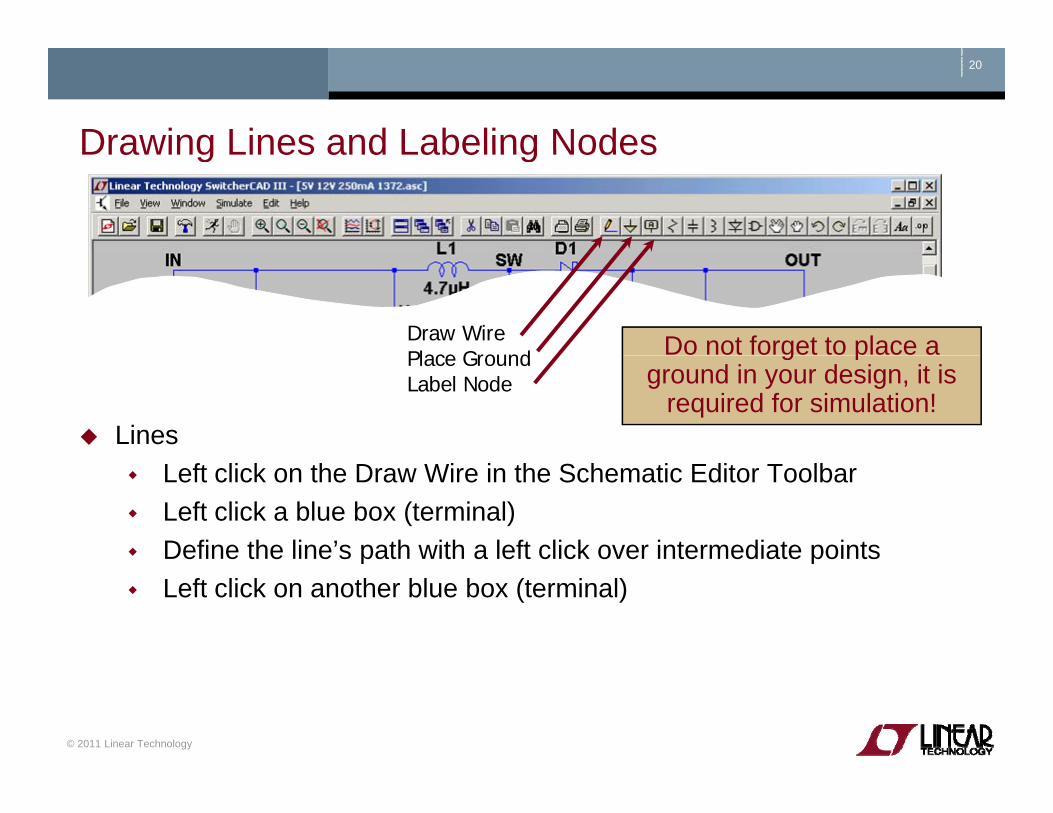
Drawing Lines and Labeling NodesDrawing Lines and Labeling Nodes
Draw WirePlace Ground Do not forget to place a
Lines
Place GroundLabel Node
g pground in your design, it is
required for simulation!
Left click on the Draw Wire in the Schematic Editor ToolbarLeft click a blue box (terminal)Define the line’s path with a left click over intermediate pointsp pLeft click on another blue box (terminal)
© 2011 Linear Technology

21
Editing Circuit Elements DeleteEditing Circuit ElementsDuplicate
MoveDragagUndo
Redo
Left click on the desired editing option
To organize your layout use the Drag option to move circuit
g pLeft click on the circuit element
To organize your layout, use the Drag option to move circuit elements around and to adjust lines between terminals
© 2011 Linear Technology
22
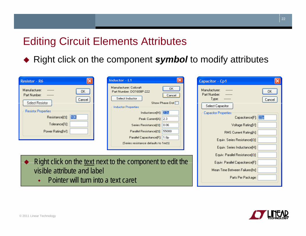
Editing Circuit Elements AttributesEditing Circuit Elements AttributesRight click on the component symbol to modify attributes
Right click on the text next to the component to edit the Right click on the text next to the component to edit the visible attribute and label
Pointer will turn into a text caret
© 2011 Linear Technology
23
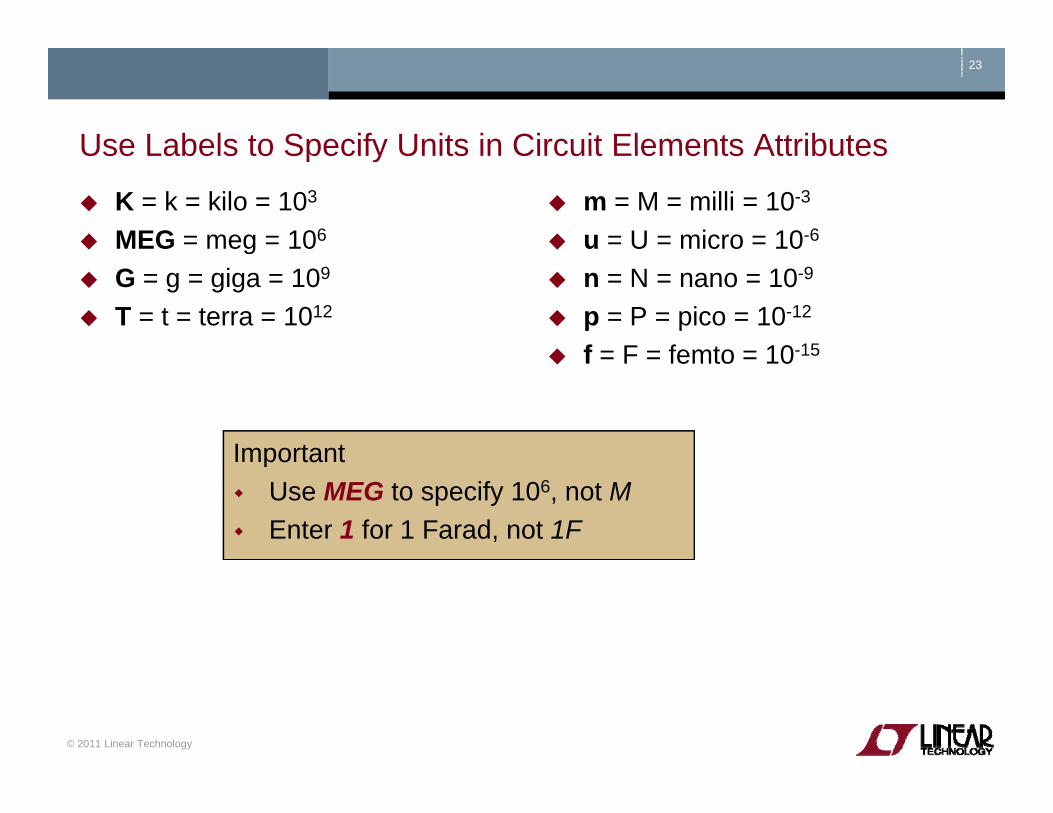
Use Labels to Specify Units in Circuit Elements AttributesUse Labels to Specify Units in Circuit Elements Attributes
K = k = kilo = 103
MEG = meg = 106
m = M = milli = 10-3
u = U = micro = 10-6gG = g = giga = 109
T = t = terra = 1012
n = N = nano = 10-9
p = P = pico = 10-12
f = F = femto = 10-15f = F = femto = 10 15
ImportantImportantUse MEG to specify 106, not MEnter 1 for 1 Farad, not 1F
© 2011 Linear Technology

24
Circuit Elements DatabaseCircuit Elements DatabaseSome components have an available database of manufacturers’ attributes
Resistors, capacitors, inductors, diodes, Bipolar transistors, MOSFET transistors, JFET transistorsIndependent voltage and current sources
To configure a component to a manufacture’s attributes
Right click on the component symbolLeft click on Select… or Pick New…Left click on a selected deviceLeft click on a selected deviceLeft click on OK
© 2011 Linear Technology
25
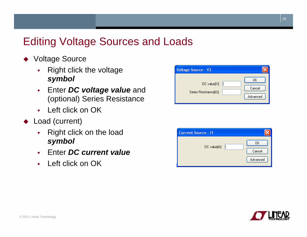
Editing Voltage Sources and LoadsEditing Voltage Sources and LoadsVoltage Source
Right click the voltage g gsymbolEnter DC voltage value and (optional) Series Resistance Left click on OK
Load (current)Right click on the loadRight click on the load symbolEnter DC current valueLeft click on OKLeft click on OK
© 2011 Linear Technology

26
Summary of Schematic Editor ToolbarSummary of Schematic Editor ToolbarPlace Circuit Element
Place DiodePlace InductorPlace Inductor
Place CapacitorPlace Resistor
Label NodePlace Ground
Draw Wire
MoveDragDragUndo
RedoRotate
Mirror
DeleteDuplicate
© 2011 Linear Technology
MirrorPlace Comment
Place SPICE directive
pPaste b/t Schematics
Find

Run and Probe a Circuit
Copyright © 2011 Linear Technology. All rights reserved.

28
Simulation CommandsSimulation CommandsTo run a simulation, specify the type of analysis to be performedpThere are six different types of analyses:
Transient analysisSmall signal ACDC sweepNoise
More information on simulation and dot commands are available in
LTspice IV User GuideNoiseDC transfer functionDC operating point
Simulation commands are placed on the schematic as textCalled dot commands
© 2011 Linear Technology
29
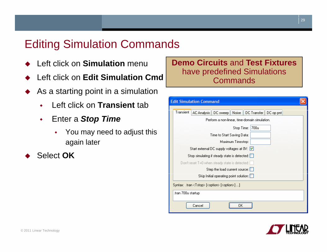
Editing Simulation CommandsEditing Simulation CommandsLeft click on Simulation menu
Left click on Edit Simulation Cmd
Demo Circuits and Test Fixtureshave predefined Simulations
C dLeft click on Edit Simulation CmdAs a starting point in a simulation
Left click on Transient tab
Commands
Enter a Stop TimeYou may need to adjust this again lateragain later
Select OK
© 2011 Linear Technology
30
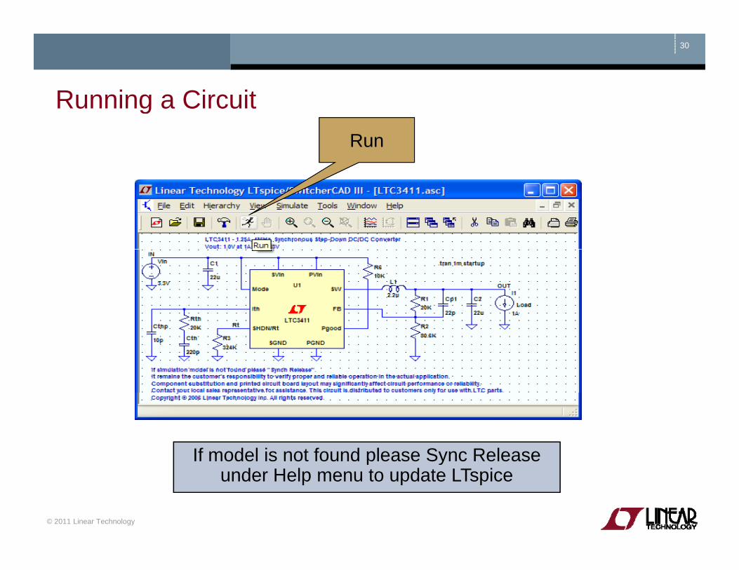
Running a CircuitRunning a CircuitRun
If model is not found please Sync Release
© 2011 Linear Technology
p yunder Help menu to update LTspice

31
Probing a Circuit & Waveform ViewerProbing a Circuit & Waveform Viewer Left click on any wire to plot the voltage on the waveform viewer
Voltage probe cursor
Left click on the body of the component to plot the current on the waveform
g p
to plot the current on the waveform viewer
Convention of positive current is in pthe direction into the pin
© 2011 Linear Technology
Current probe cursor

32
Probing a Demo Circuit and Test FixtureProbing a Demo Circuit and Test FixtureDemo Circuits and Test Fixtures have INs and OUTs clearly labeled to help you quickly select themp y q yTo view the waveform left click on IN and OUT
L ft Cli kLeft Click Left Click Here for Output
Waveform
Left Click Here for
Input Waveform WaveformWaveform
© 2011 Linear Technology

33
Voltage Differences Across NodesVoltage Differences Across NodesLeft click and hold on one node and drag the mouse gto another node
Red voltage probe at the first nodenodeBlack probe on the second
Differential voltages are displayed in the waveform
viewerviewer
© 2011 Linear Technology

34
Plot PlanesPlot PlanesMultiple plot panes can be displayed on one window to allow better separation between traces permitting different traces to be i d d tl t l dindependently autoscaled
Right click in the waveform paneSelect Add Plot PaneLeft click and hold to drag a label to a new plot pane
© 2011 Linear Technology
35
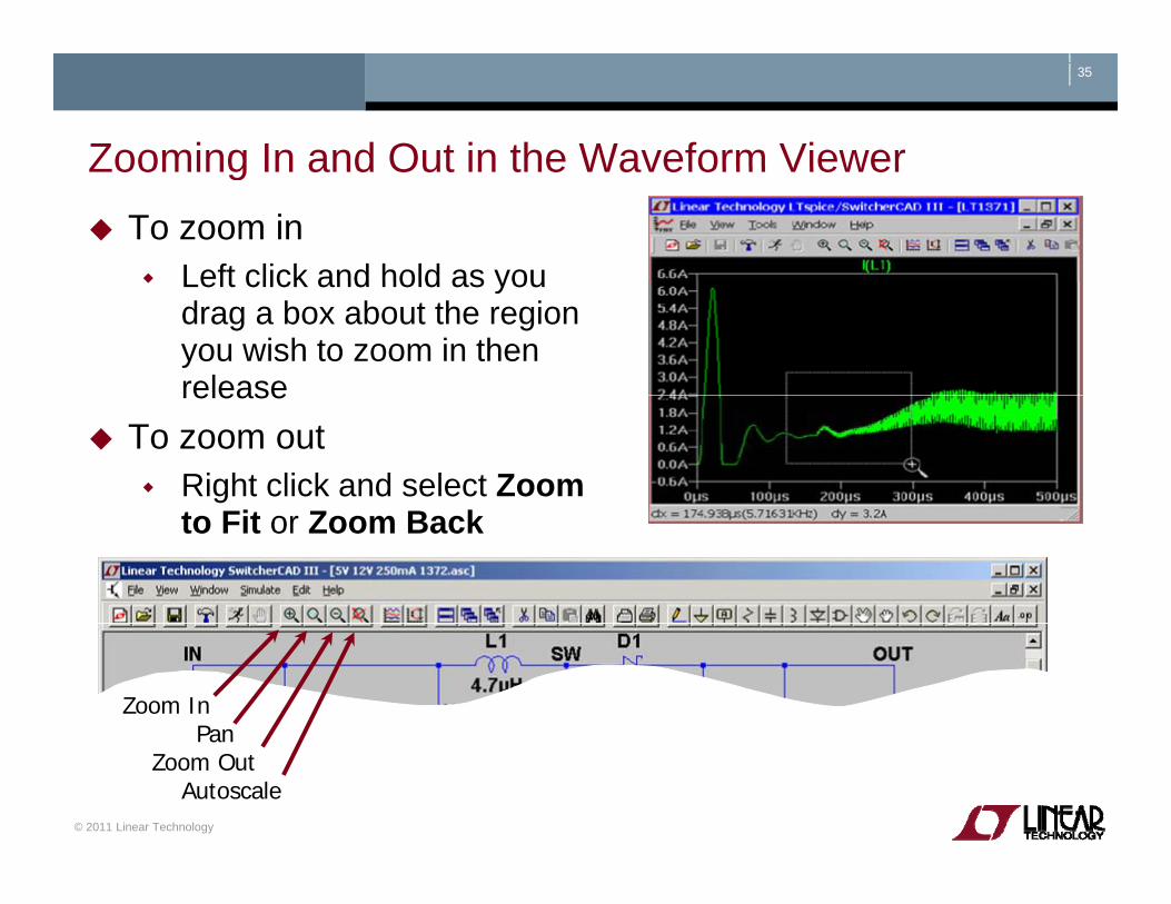
Zooming In and Out in the Waveform ViewerZooming In and Out in the Waveform ViewerTo zoom in
Left click and hold as youLeft click and hold as you drag a box about the region you wish to zoom in then releaserelease
To zoom outRight click and select Zoom to Fit or Zoom Back
Zoom InPan
© 2011 Linear Technology
PanZoom Out
Autoscale

36
Measuring VRi l IRi l and Time (Frequency)Measuring VRipple, IRipple and Time (Frequency)Drag a box about the region you wish to measure (peak to peak over a period)
Left click and hold to drag a box over the portion of interestView the lower left hand side of the screen
To avoid resizing shrink your box before you let go of the left mouseTo avoid resizing, shrink your box before you let go of the left mouse click or use the Undo command in the Edit menu
T i SMPS lt i l illTo view SMPS voltage ripple you will need to zoom into a narrow section
since waveform is initially compressed to full rangeco p essed to u a ge
© 2011 Linear Technology
37
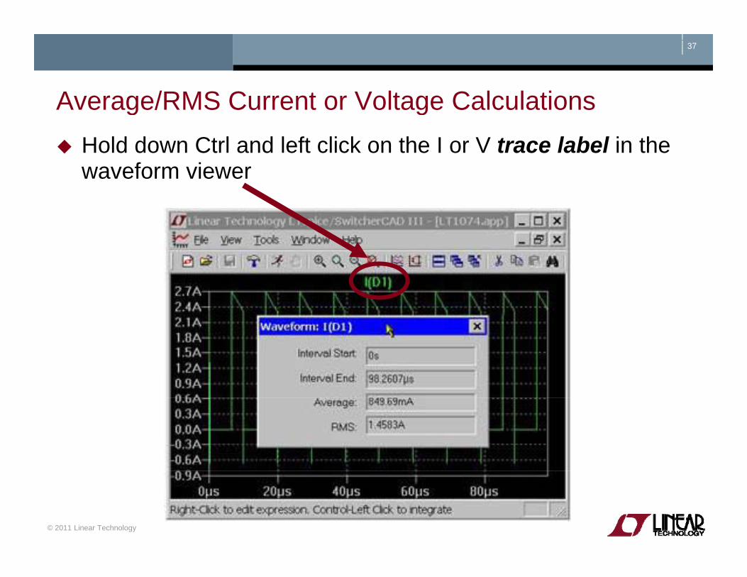
Average/RMS Current or Voltage CalculationsAverage/RMS Current or Voltage Calculations Hold down Ctrl and left click on the I or V trace label in the waveform viewer
© 2011 Linear Technology

38
Instantaneous & Average Power DissipationInstantaneous & Average Power DissipationInstantaneous Power Dissipation
Hold down the ALT key and yleft click on the symbol of the componentPointer will change to a thermometer Plotted in units of Watts
Average Power Dissipation Hold down the Ctrl key and left click on the trace labelleft click on the trace labelpower dissipation waveform
© 2011 Linear Technology

Generating a BOM and Efficiency Report
Copyright © 2011 Linear Technology. All rights reserved.
40
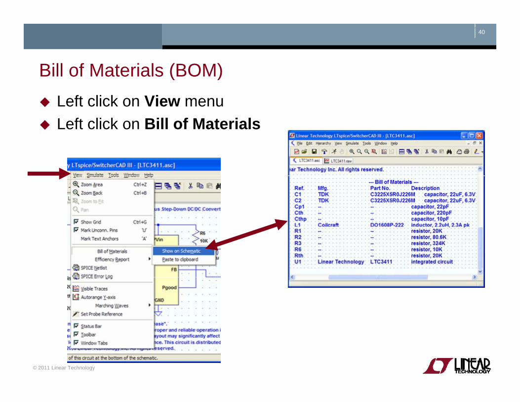
Bill of Materials (BOM)Bill of Materials (BOM)Left click on View menuLeft click on Bill of MaterialsLeft click on Bill of Materials
© 2011 Linear Technology

41
Computing Efficiency of SMPS CircuitsComputing Efficiency of SMPS CircuitsLeft click on Simulate menuLeft click on Edit Simulation CmdLeft click on Edit Simulation CmdLeft click on Stop simulating if steady state is detected
Automatically detect the steady state by checking the internal y y y gstate of the macromodels
Rerun simulation Automatic detection of steady state may not work – steady state detection may be too strict or lenient
© 2011 Linear Technology
42
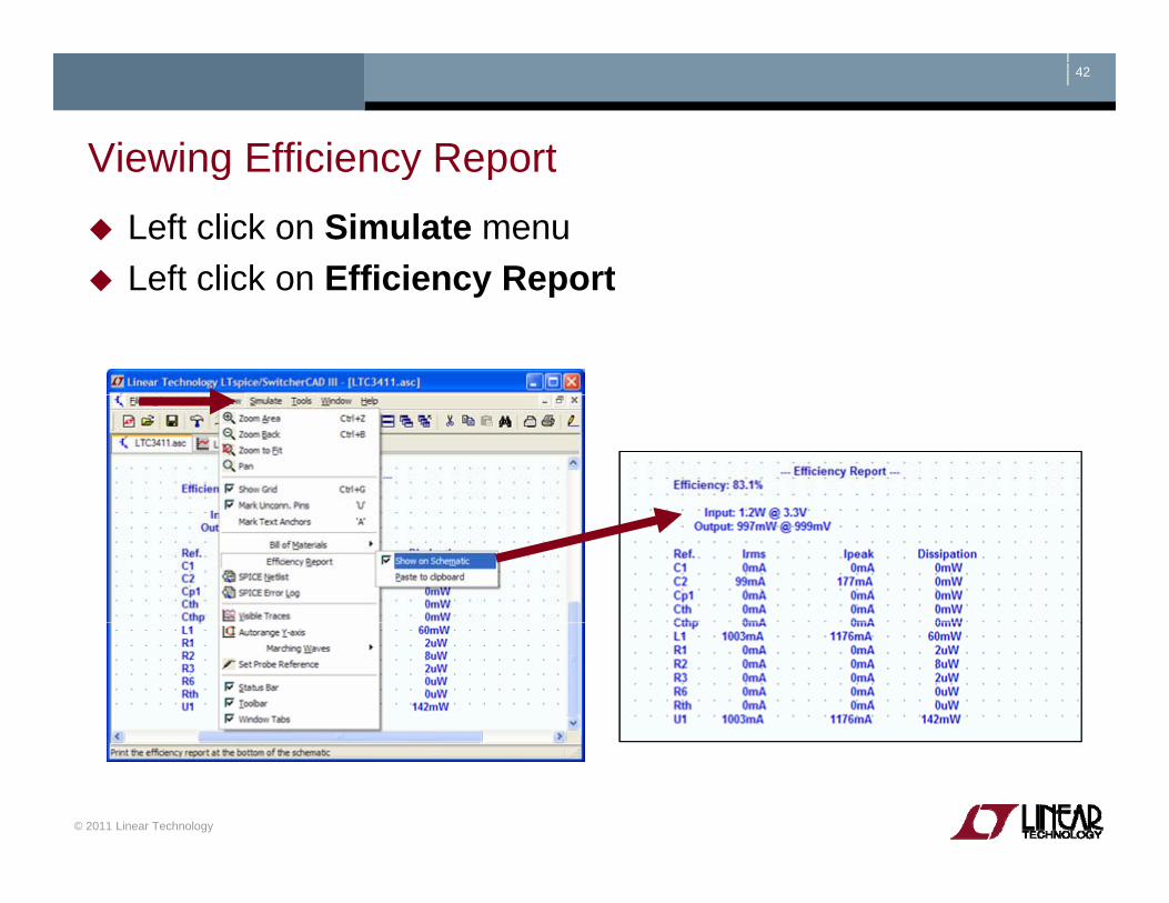
Viewing Efficiency ReportViewing Efficiency ReportLeft click on Simulate menuLeft click on Efficiency ReportLeft click on Efficiency Report
© 2011 Linear Technology
Simulate a Transient Response in a SMPSAdvanced Topic
Copyright © 2011 Linear Technology. All rights reserved.

44
Use a Pulsed Function as a Transient Response LoadUse a Pulsed Function as a Transient Response Load Insert a current source load
Left click on the Component symbol in the Schematic Editor Toolbarp ySelect load (or load2) circuit element and configure as pulsedLeft click on OK
Configure load as a pulsed function (covered next)Configure load as a pulsed function (covered next)Steps current from initial to pulsed value and back
Run and review results
© 2011 Linear Technology
45
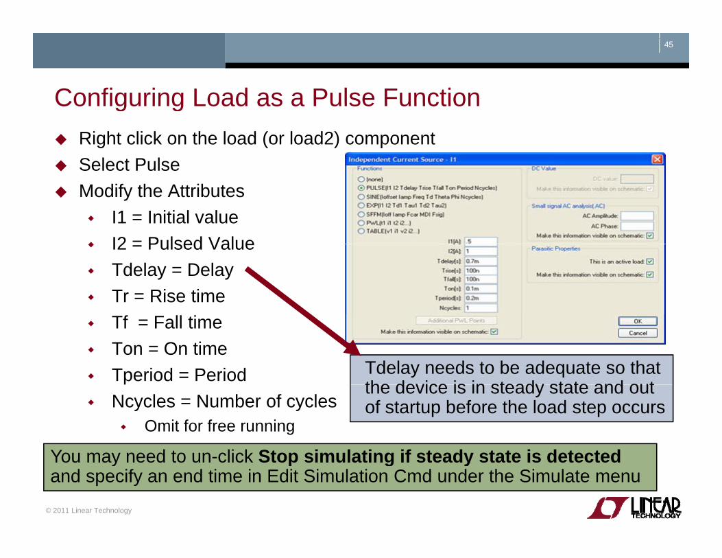
Configuring Load as a Pulse FunctionConfiguring Load as a Pulse FunctionRight click on the load (or load2) componentSelect PulseModify the Attributes
I1 = Initial valueI2 = Pulsed ValueI2 = Pulsed ValueTdelay = DelayTr = Rise timeTf = Fall timeTon = On timeTperiod = Period Tdelay needs to be adequate so that
the device is in steady state and outNcycles = Number of cycles
Omit for free running
the device is in steady state and out of startup before the load step occurs
You may need to un click Stop simulating if steady state is detected
© 2011 Linear Technology
You may need to un-click Stop simulating if steady state is detected and specify an end time in Edit Simulation Cmd under the Simulate menu

Simulate a TransformerAdvanced Topic
Copyright © 2011 Linear Technology. All rights reserved.
47
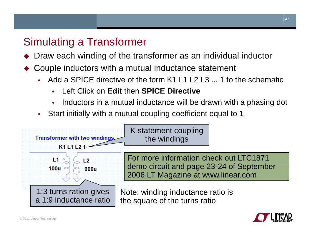
Simulating a TransformerSimulating a TransformerDraw each winding of the transformer as an individual inductorCouple inductors with a mutual inductance statement
Add a SPICE directive of the form K1 L1 L2 L3 ... 1 to the schematicLeft Click on Edit then SPICE DirectiveInductors in a mutual inductance will be drawn with a phasing dotInductors in a mutual inductance will be drawn with a phasing dot
Start initially with a mutual coupling coefficient equal to 1
K statement coupling p gthe windings
For more information check out LTC1871 d i it d 23 24 f S t b
1:3 turns ration gives Note: winding inductance ratio is
demo circuit and page 23-24 of September 2006 LT Magazine at www.linear.com
© 2011 Linear Technology
ga 1:9 inductance ratio
gthe square of the turns ratio
Additional Information and Support
Copyright © 2011 Linear Technology. All rights reserved.
49
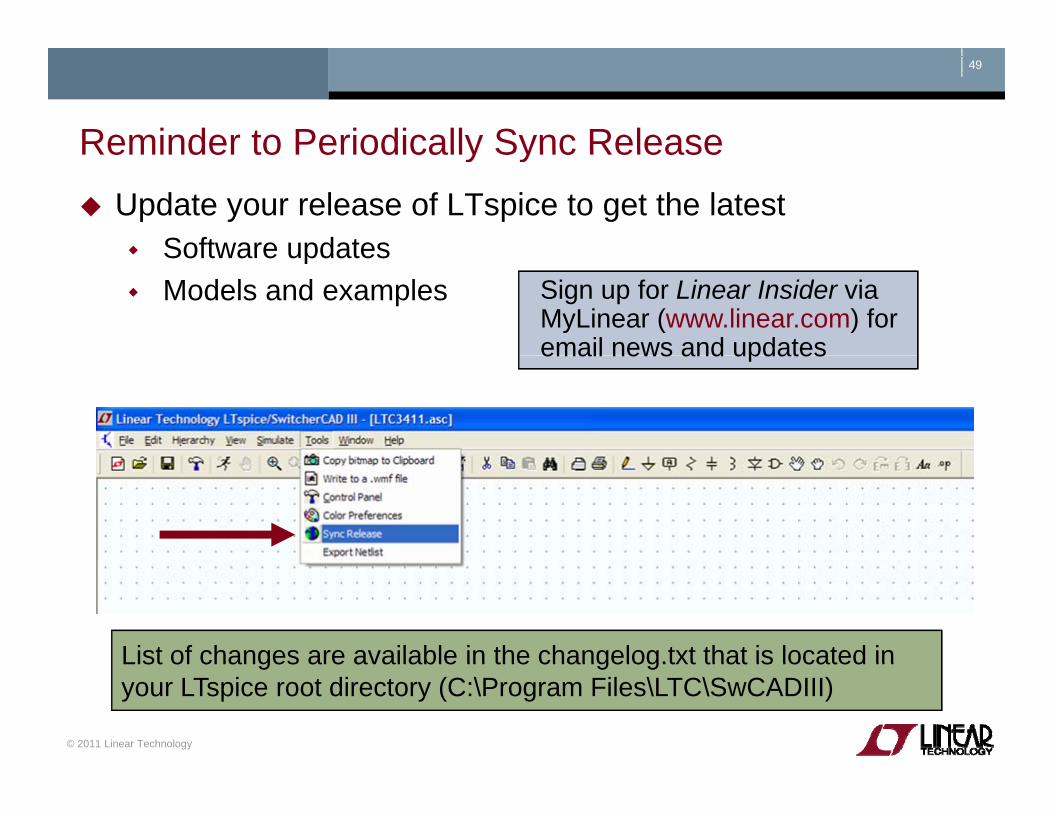
Reminder to Periodically Sync ReleaseReminder to Periodically Sync ReleaseUpdate your release of LTspice to get the latest
Software updatesSoftware updatesModels and examples Sign up for Linear Insider via
MyLinear (www.linear.com) for email news and updatesemail news and updates
List of changes are available in the changelog.txt that is located in
© 2011 Linear Technology
List of changes are available in the changelog.txt that is located in your LTspice root directory (C:\Program Files\LTC\SwCADIII)
50
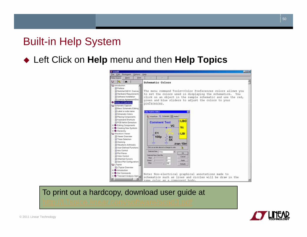
Built-in Help SystemBuilt in Help SystemLeft Click on Help menu and then Help Topics
To print out a hardcopy download user guide at
© 2011 Linear Technology
To print out a hardcopy, download user guide at http://LTspice.linear.com/software/scad3.pdfhttp://LTspice.linear.com/software/scad3.pdf

51
Emailing Comments and Signing up for Linear InsiderEmailing Comments and Signing up for Linear Insider
© 2011 Linear Technology

52
Customer SupportCustomer SupportLinear Technology customers can obtain support by
Calling your local field applications engineerCalling your local field applications engineerhttp://www.linear.com/contact/
Calling +1 (408) 432 – 1900 for factory application support Additional support (not related to Linear Technology circuits or models support)
Built-in help topics & User ManualBuilt in help topics & User ManualIndependent LTspice users’ group (search messages)
Simulation with the supplied models is fully supportedAll bug reports are appreciated and will be resolved
© 2011 Linear Technology
g p pp
53
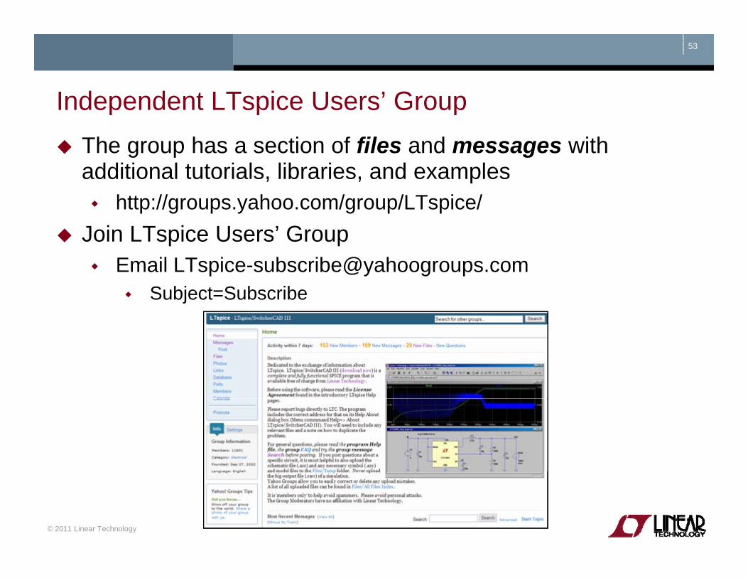
Independent LTspice Users’ GroupIndependent LTspice Users GroupThe group has a section of files and messages with additional tutorials, libraries, and examples, , p
http://groups.yahoo.com/group/LTspice/Join LTspice Users’ Group
Email [email protected]=Subscribe
© 2011 Linear Technology