ltg filtration technology
TRANSCRIPT

LTG Filtration TechnologyFor clean air.For recovering valuable materials.

Successful applications in many industries
APPLICATION SOLUTIONS
2 © LTG Aktiengesellschaft
The individual components of LTG fi lter technology ensure clean air in the production premises of many diff erent industries. They catch, transport, fi lter, compact and separate fi bres, dusts and other particles.This way, they help increase product quality, lower production costs, recover raw materials, keep employees healthy and ensure compliance with environmental protection standards.
Continuous Explosionprotected
Separating QualityRecycling Emissionreducing
ppm
Compacting
Applications
Textile technology / technical textiles Building and insulation materials
Medical technologyNonwoven
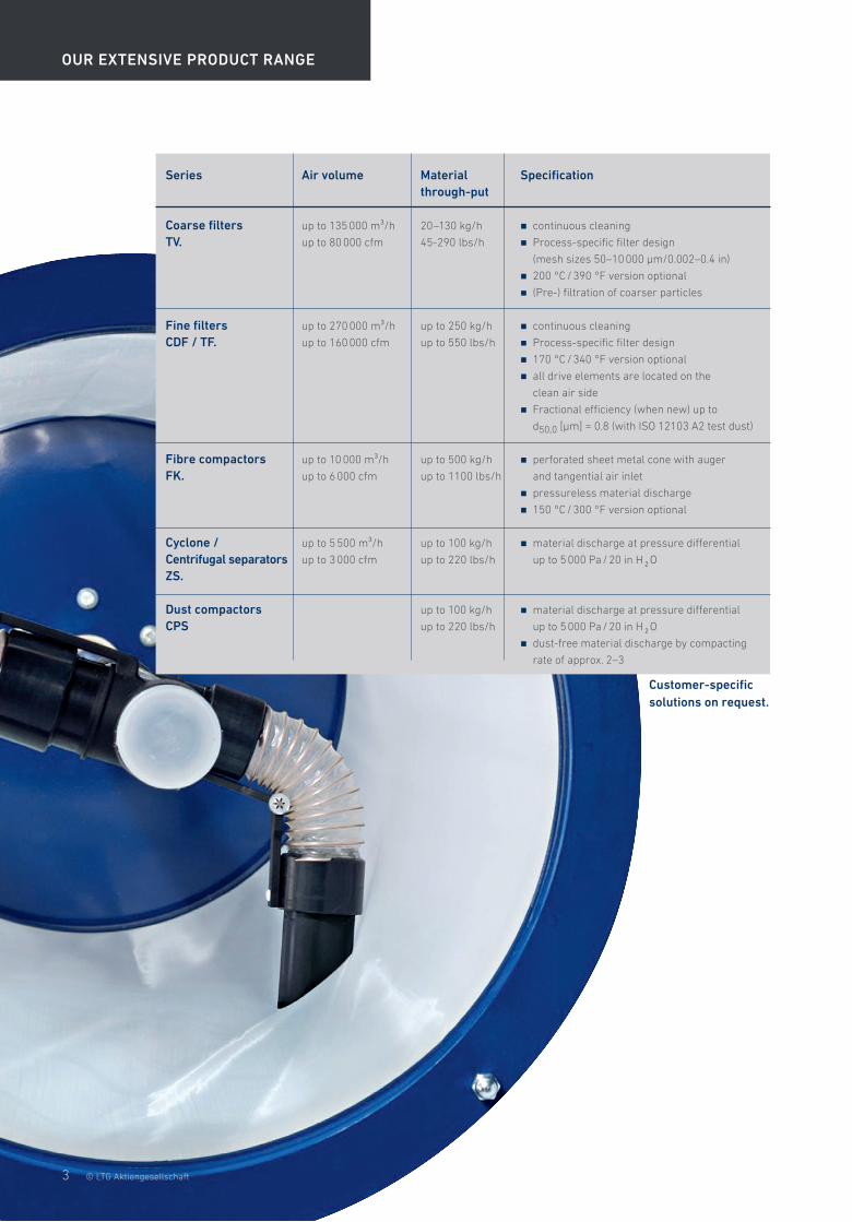
OUR EXTENSIVE PRODUCT RANGE
© LTG Aktiengesellschaft
Series
Coarse filtersTV.
Fine filtersCDF / TF.
Fibre compactorsFK.
Cyclone / Centrifugal separators ZS.
Dust compactorsCPS
Air volume
up to 135 000 m³/h
up to 80 000 cfm
up to 270 000 m³/h
up to 160 000 cfm
up to 10 000 m³/h
up to 6 000 cfm
up to 5 500 m³/h
up to 3 000 cfm
Material through-put
20–130 kg/h
45-290 lbs/h
up to 250 kg/h
up to 550 lbs/h
up to 500 kg/h
up to 1100 lbs/h
up to 100 kg/h
up to 220 lbs/h
up to 100 kg/h
up to 220 lbs/h
Specification
� continuous cleaning
� Process-specific filter design
(mesh sizes 50–10 000 μm/0.002–0.4 in)
� 200 °C / 390 °F version optional
� (Pre-) filtration of coarser particles
� continuous cleaning
� Process-specific filter design
� 170 °C / 340 °F version optional
� all drive elements are located on the
clean air side
� Fractional efficiency (when new) up to
d50,0 [μm] = 0.8 (with ISO 12103 A2 test dust)
� perforated sheet metal cone with auger
and tangential air inlet
� pressureless material discharge
� 150 °C / 300 °F version optional
� material discharge at pressure differential
up to 5 000 Pa / 20 in H 2 O
� material discharge at pressure differential
up to 5 000 Pa / 20 in H 2 O
� dust-free material discharge by compacting
rate of approx. 2–3
Customer-specific solutions on request.
3

Main airfl ow withfi bres and dust
Prefi lter
Secondary airfl ow 1 Separation/compacting
of coarse particles in thefi bre compactor
Valuable materials
Secondary airfl ow 2 withhigh dust concentration
The systems made from LTG fi lter components have a modular design and are continuously self-cleaning. They effi ciently fi lter and separate solids such as particles, dust, fi bres, chips and granulates from the production process, thus recovering valuable materials or disposing of waste that can no longer be used.
The various fi lter stages
Functionality of Filtration Technology:Customised fi lter solutions for clean processes and healthy working conditions
LTG FILTRATION TECHNOLOGY
4 © LTG Aktiengesellschaft
LTG fi lters mechanically separate solid particles from waste air in machinery and factory buildings. The fi ltration takes place in several steps depending on particle size and required air purity. There are three basic steps:
� Coarse fi ltration (also called pre-fi ltration),
� Fine fi ltration and
� Micro-fi ltration of particles.
Fine fi ltrationA continuously self-cleaning fi ne fi lter separates any dust still remaining in the airstream almost completely. The airfl ow through the fi lter drums is from the inside to the outside. The dust collected on the fi lter media, is continuously vacuumed off by rotating nozzles and passed to a cyclone separator.
All drive elements are located on the clean air side.
The fi lter surface is adapted to the requirements by changing the number of fi lter drums.
Coarse fi ltrationA continuously self-cleaning prefi lter separates fi bres and coarse particles using a fi lter media. The vacuumed off coarse particles are taken to a separator with a conveying fan.
Secondary airfl ow 1 and 2The cleaning of both prefi lter and fi ne fi lter is done by suction nozzles.The necessary pressure and volume fl ow is generated by fans. Fibres and dust are discharged without pressure from the respective secondary circuit. The fi bre compactor and the cyclone, if required with an additional compacting power screw, are used for this.
The materials recovered can be returned to the production process.

Secondary airfl ow 2Separation/compactingof fi ne particles in thecyclone
Valuable materials
Fine dust is extracted andconveyed to the cyclone
Fine fi lter
Secondary airfl ow 2 withhigh dust concentration
Clean air
Secondary airfl ow 1 withhigh fi bre concentration
Separation andcompacting of coarseparticles in the fi brecompactor
Fanmain airfl ow
Separation of fi neparticles in the cyclone
5© LTG Aktiengesellschaft
� Process temperatures up to
200 °C / 390 °F
� Customer-specifi c solutions
� High fi ltration output
� Recovery of valuable materials
� Continuous operation
� Energy-effi cient
� Pressure surge-free
� Low maintenance
� Modular and space-saving structure
� Low operating costs
� Direct installation at the production
process is possible
� High performance density
� Long service life of fi lter media
� Explosion-proof models available
Advantages

LTG Engineering Services
6© LTG Aktiengesellschaft
R&D / START-UP
Use the innovative power and inventive spirit of the LTG engineers for ideal results in your plant.
� Development of customer-specifi c products
� Individual prototype construction
� System commissioning and plant service
� Assessment of new concepts before they are
implemented
� Review of fans
LABORATORY TEST / EXPERIMENT
Secure air handling plans in advance. Use the full the potential of existing systems.
� Optimisation of thermal comfort
� Precise imitation (mock-up)
� Visualisation of fl ows
� Optimisation of acoustics
� Determination of the required threshold speeds for
transport and thermal processes
� Measurement of fl ow profi les
� Measurement of customer-specifi c special fans
� Project-specifi c product optimisations
FIELD MEASUREMENT / OPTIMISATION
We review and optimise your ventilation concept or your production process right on site.
� Optimisation of thermal comfort
� Optimisation of existing air conditioning
facilities
� Energetic optimisation
� Review and calibration of airstream simulators
� Determination of boundary parameters such
as speed, pressure, temperature, humidity or
geometries
� Visualisation of fl ows
� Acoustic measurements
� Duct work measurements
SIMULATION / EXPERTISE
No matter if you need an air conditioning concept or a new production process: use state of the art simulation tools even in the planning stage.
� Computer-based fl ow simulation CFD
� Finite-element method
� Development of energy-effi cient fl ow concepts
� Simulation of fi bre treatment and sifter
processes
� Simulation of temperature adjustment
processes
� Wind simulation

Filtration
A fi xed fi lter drum routes the air fl ow from the inside out. Dust is extracted continually inside the fi lter, reducing the space with a high dust load to a minimum. The drive elements are easily accessible on the clean gas side and protected from contamination. The modular build makes it possible to adjust the system to many diff erent process conditions.
The material previously separated is picked up by a horizontal compacting screw and discharged. An agitator ensures an even feed to the screw and prevents clogging. The material is compacted by a metal spring diaphragm.
The airstream carrying coarse particles enters the unit at the top, then passes through a perforated sheet metal cone. The airborne solids accumulate on the inside of the perforated sheet metal cone and are continuously stripped off by an auger, pushed down, compacted and discharged at zero pressure at the bottom.
The airstream carrying fi ne particles enters the cyclone (centrifugal separator) tangentially at the top. The solids are carried to the outside by the rotating centrifugal airfl ow and pass spirally either to the collecting container or to the dust compactor mounted underneath.
Separating and Compacting
7© LTG Aktiengesellschaft
The airstream carrying coarse particles passes through a fi lter media. The mesh size can be adjusted to the particle size. The fi lter media is cleaned with continuous suction.
The dusty air passes through the fi lter drums from the inside so that the dust deposits on the inner surface from where it is continuously removed by rotating suction nozzles. Continuous cleaning provides a constant pressure level in the system. All drive elements are located on the clean air side and are thus protected from pollution.
Coarse fi lter TVM / TVN Fine fi lter CDF Drum fi lter TFB / TFC
Fibre compactor FK. Cyclone ZS. Dust compactor CPS

LTG Aktiengesellschaft
Grenzstrasse 7
70435 Stuttgart
Deutschland
Tel.: +49 (711) 8201-0
Fax: +49 (711) 8201-720
E-Mail: [email protected]
www.LTG.de
LTG Incorporated
105 Corporate Drive, Suite E
Spartanburg, SC 29303
USA
Tel.: +1 (864) 599-6340
Fax: +1 (864) 599-6344
E-Mail: [email protected]
www.LTG-INC.net
Comfort Air Technology
Air-Water Systems
Air Diff users
Air Distribution
Process Air Technology
Fans
Filtration Technology
Humidifi cation Technology
Engineering Services
Laboratory Test / Experiment
Field Measurement / Optimisation
Simulation / Expertise
R&D / Start-up
451-06 [05/19] Technical changes reserved. © LTG Aktiengesellschaft, Stuttgart