lte sib info
DESCRIPTION
LTE, 3GPP, SIB InfoTRANSCRIPT
7/15/2019 Lte Sib Info
http://slidepdf.com/reader/full/lte-sib-info 1/187
3GPP TS 36.508 V8.3.0 (2009-09)
Technical Specification
3rd Generation Partnership Project;Technical Specif ication Group Radio Access Network;Evolved Universal Terrestrial Radio Access (E-UTRA)
andEvolved Packet Core (EPC);Common test environments for User Equipment (UE)
conformance testing(Release 8)
The present document has been developed within the 3 rd Generation Partnership Project (3GPP TM) and may be further elaborated for the purposes of 3GPP. The present document has not been subject to any approval process by the 3GPP Organizational Partners and shall not be implemented.This Specification is provided for future development work within 3GPP only. The Organizational Partners accept no liability for any use of this Specification.Specifications and reports for implementation of the 3GPP TM system should be obtained via the 3GPP Organizational Partners' Publications Offices.
7/15/2019 Lte Sib Info
http://slidepdf.com/reader/full/lte-sib-info 2/187
3GPP
3GPP TS 36.508 V8.3.0 (2009-09)2Release 8
Keywordsmobile, UE, terminal, testing, LTE
3GPP
Postal address
3GPP support office address650 Route des Lucioles - Sophia Antipolis
Valbonne - FRANCETel.: +33 4 92 94 42 00 Fax: +33 4 93 65 47 16
Internethttp://www.3gpp.org
Copyright Notification
No part may be reproduced except as authorized by written permission.The copyright and the foregoing restriction extend to reproduction in all media.
© 2009, 3GPP Organizational Partners (ARIB, ATIS, CCSA, ETSI, TTA, TTC).All rights reserved.
UMTS™ is a Trade Mark of ETSI registered for the benefit of its members3GPP™ is a Trade Mark of ETSI registered for the benefit of its Members and of the 3GPP Organizational PartnersLTE™ is a Trade Mark of ETSI currently being registered for the benefit of its Members and of the 3GPP Organizational PartnersGSM® and the GSM logo are registered and owned by the GSM Association
7/15/2019 Lte Sib Info
http://slidepdf.com/reader/full/lte-sib-info 3/187
3GPP
3GPP TS 36.508 V8.3.0 (2009-09)3Release 8
Contents
Contents..............................................................................................................................................................3
Foreword ..........................................................................................................................................................10 Introduction ......................................................................................................................................................10
1 Scope......................................................................................................................................................11
2 References..............................................................................................................................................11
3 Definitions, symbols and abbreviations .................................................................................................13 3.1 Definitions ............................................................... ....................................................................... ................. 13 3.2 Symbols ............................................................... ................................................................ ............................ 13 3.3 Abbreviations................................................................................................................................................... 13
4 Common test environment .....................................................................................................................14 4.1 Environmental conditions................................................................................................................................ 14 4.1.1 Temperature ........................................................... ................................................................... ................. 14 4.1.2 Voltage....................................................................................................................................................... 14 4.2 Common requirements of test equipment ......................................................................... ............................... 14 4.2.1 General functional requirements ............................................................. .................................................. 15 4.2.2 Minimum functional requirements............................................................................................................ 15 4.2.2.1 Supported Cell Configuration............................................................................................................... 15 4.2.2.1.1 Supported Channels ............................................................... ......................................................... 16 4.2.2.2 Support of Tcell timing offset................................................................................................................. 17 4.3 Reference test conditions................................................................................................................................. 17 4.3.1 Test frequencies .................................................................... .............................................................. ....... 17 4.3.1.1 FDD Mode Test frequencies......................................................... ........................................................ 17 4.3.1.1.1 FDD reference test frequencies for operating band 1...................................................................... 17 4.3.1.1.2 FDD reference test frequencies for operating band 2...................................................................... 18 4.3.1.1.3 FDD reference test frequencies for operating band 3...................................................................... 18 4.3.1.1.4 FDD reference test frequencies for operating band 4...................................................................... 18 4.3.1.1.5 FDD reference test frequencies for operating band 5...................................................................... 19 4.3.1.1.6 FDD reference test frequencies for operating band 6...................................................................... 19 4.3.1.1.7 FDD reference test frequencies for operating band 7...................................................................... 19 4.3.1.1.8 FDD reference test frequencies for operating band 8...................................................................... 20 4.3.1.1.9 FDD reference test frequencies for operating band 9...................................................................... 20 4.3.1.1.10 FDD reference test frequencies for operating band 10.................................................................... 20 4.3.1.1.11 FDD reference test frequencies for operating band 11.................................................................... 21 4.3.1.1.12 FDD reference test frequencies for operating band 12.................................................................... 21 4.3.1.1.13 FDD reference test frequencies for operating band 13.................................................................... 21 4.3.1.1.14 FDD reference test frequencies for operating band 14.................................................................... 22 4.3.1.1.15 FDD reference test frequencies for operating band 15.................................................................... 22 4.3.1.1.16 FDD reference test frequencies for operating band 16.................................................................... 22 4.3.1.1.17 FDD reference test frequencies for operating band 17.................................................................... 22 4.3.1.1.18 FDD reference test frequencies for operating band 18.................................................................... 22 4.3.1.1.19 FDD reference test frequencies for operating band 19.................................................................... 23 4.3.1.2 TDD Mode Test frequencies ........................................................... ..................................................... 23 4.3.1.2.1 TDD reference test frequencies for Operating Band 33.................................................................. 23 4.3.1.2.2 TDD reference test frequencies for Operating Band 34.................................................................. 23 4.3.1.2.3 TDD reference test frequencies for Operating Band 35.................................................................. 24 4.3.1.2.4 TDD reference test frequencies for Operating Band 36.................................................................. 24 4.3.1.2.5 TDD reference test frequencies for Operating Band 37.................................................................. 24 4.3.1.2.6 TDD reference test frequencies for Operating Band 38.................................................................. 25 4.3.1.2.7 TDD reference test frequencies for Operating Band 39.................................................................. 25 4.3.1.2.8 TDD reference test frequencies for Operating Band 40.................................................................. 25 4.3.2 Radio conditions......................................................................................................................................... 25 4.3.2.1 Normal propagation condition.... ..................................................................... ..................................... 25 4.3.3 Physical channel allocations....................................................................................................................... 25

7/15/2019 Lte Sib Info
http://slidepdf.com/reader/full/lte-sib-info 4/187
3GPP
3GPP TS 36.508 V8.3.0 (2009-09)4Release 8
4.3.3.1 Antennas............................................................................................................................................... 25 4.3.3.2 Downlink physical channels and physical signals................................................................................ 26 4.3.3.3 Mapping of downlink physical channels and signals to physical resources ......................................... 26 4.3.3.5 Mapping of uplink physical channels and signals to physical resources.............................................. 28 4.3.4 Signal levels ................................................................ .............................................................. ................. 29 4.3.4.1 Downlink signal levels ............................................................... .......................................................... 29
4.3.4.2 Uplink signal levels ............................................................... ............................................................... 29 4.3.5 Standard test signals................................................................................................................................... 29 4.3.5.1 Downlink test signals............................................................................................................................ 29 4.3.5.2 Uplink test signals ................................................................. ............................................................... 29 4.3.6 Physical layer parameters........................................................................................................................... 30 4.3.6.1 Downlink physical layer parameters ............................................................... ..................................... 30 4.3.6.1.1 Physical layer parameters for DCI format 0.................................................................................... 30 4.3.6.1.2 Physical layer parameters for DCI format 1.................................................................................... 31 4.3.6.1.3 Physical layer parameters for DCI format 1A................................................................................. 31 4.3.6.1.4 Physical layer parameters for DCI format 1C................................................................................. 32 4.3.6.1.5 Physical layer parameters for DCI format 2.................................................................................... 32 4.3.6.1.6 Physical layer parameters for DCI format 2A................................................................................. 33 4.4 Reference system configurations ...................................................................... ............................................... 33
4.4.1 Simulated network scenarios...................................................................................................................... 33 4.4.1.1 Single cell network scenarios ............................................................ ................................................... 33 4.4.1.2 Intra E-UTRA multi cell network scenarios......................................................................................... 34 4.4.1.3 Dual mode network scenarios............................................................................................................... 34 4.4.1.4 3GPP Inter-RAT network scenarios ............................................................ ......................................... 34 4.4.1.5 3GPP2 Inter-RAT network scenarios ............................................................ ....................................... 34 4.4.2 Simulated cells ................................................................. .................................................................... ...... 34 4.4.3 Common parameters for simulated E-UTRA cells..................................................................................... 36 4.4.3.1 Common configurations of system information blocks........................................................................ 36 4.4.3.1.1 Combinations of system information blocks................................................................................... 36 4.4.3.1.2 Scheduling of system information blocks....................................................................................... 38 4.4.3.2 Common contents of system information messages............................................................................. 39 - MasterInformationBlock ....................................................................................................................... 39
- SystemInformation................................................................................................................................ 40 - SystemInformationBlockType1 ............................................................................................................. 41 4.4.3.3 Common contents of system information blocks.................................................................................. 42 - SystemInformationBlockType2 ............................................................................................................. 42 - SystemInformationBlockType3 ............................................................................................................. 43 - SystemInformationBlockType4 ............................................................................................................. 43 - SystemInformationBlockType5 ............................................................................................................. 44 - SystemInformationBlockType6 ............................................................................................................. 46 - SystemInformationBlockType7 ............................................................................................................. 47 - SystemInformationBlockType8 ............................................................................................................. 48 - SystemInformationBlockType9 ............................................................................................................. 50 - SystemInformationBlockType10 ........................................................................................................... 50 - SystemInformationBlockType11 ........................................................................................................... 51
4.4.3.4 Channel-bandwidth-dependent parameters in system information blocks ........................................... 51 4.4.4 Common parameters for simulated UTRA cells .......................................................................... .............. 51 4.4.4.1 Common contents of system information blocks for UTRA cells........................................................ 52 - System Information Block type 19....................................................................................................... 52 4.4.4.2 UTRA SIB scheduling for inter EUTRA - UTRA test......................................................................... 52 4.4.4.3 UTRA SIB scheduling for inter EUTRA – UTRA - GERAN test ....................................................... 53 4.4.5 Common parameters for simulated GERAN cells .................................................................. ................... 54 4.4.6 Common parameters for simulated CDMA2000 cells ...................................................................... ......... 54 4.4.7 Default parameters specific for simulated cells.......................................................................................... 54 4.5 Generic procedures ................................................................ .................................................................... ...... 54 4.5.1 UE test states.............................................................................................................................................. 55 4.5.2 UE Registration (State 2) ................................................................. .......................................................... 56 4.5.2.1 Initial conditions................................................................................................................................... 56
4.5.2.2 Definition of system information messages.......................................................................................... 56 4.5.2.3 Procedure.............................................................................................................................................. 57 4.5.2.4 Specific message contents .................................................................... ................................................ 58 4.5.2A UE Registration, UE Test Mode Activated (State 2A)............................................................................... 58

7/15/2019 Lte Sib Info
http://slidepdf.com/reader/full/lte-sib-info 5/187
3GPP
3GPP TS 36.508 V8.3.0 (2009-09)5Release 8
4.5.2A.1 Initial conditions................................................................................................................................... 58 4.5.2A.2 Definition of system information messages.......................................................................................... 58 4.5.2A.3 Procedure.............................................................................................................................................. 59 4.5.2A.4 Specific message contents .................................................................... ................................................ 59 4.5.3 Generic Radio Bearer Establishment (State 3)........................................................................................... 60 4.5.3.1 Initial conditions................................................................................................................................... 60
4.5.3.2 Definition of system information messages.......................................................................................... 60 4.5.3.3 Procedure.............................................................................................................................................. 61 4.5.3.4 Specific message contents .................................................................... ................................................ 62 4.5.3A Generic Radio Bearer Establishment, UE Test Mode Activated (State 3A) .............................................. 62 4.5.3A.1 Initial conditions................................................................................................................................... 62 4.5.3A.2 Definition of system information messages.......................................................................................... 62 4.5.3A.3 Procedure.............................................................................................................................................. 63 4.5.3A.4 Specific message contents .................................................................... ................................................ 63 4.5.4 Loopback Activation (State 4) ............................................................... .................................................... 63 4.5.4.1 Initial conditions................................................................................................................................... 63 4.5.4.2 Definition of system information messages.......................................................................................... 63 4.5.4.3 Procedure.............................................................................................................................................. 63 4.5.4.4 Specific message contents .................................................................... ................................................ 63
4.6 Default RRC message and information elements contents .............................................................. ................ 63 4.6.1 Contents of RRC messages ............................................................ ............................................................ 64 – CounterCheck ....................................................................................................................................... 64 – CounterCheckResponse........................................................................................................................ 64 – CSFBParametersRequestCDMA2000 .................................................................................................. 64 – CSFBParametersResponseCDMA2000................................................................................................ 65 – DLInformationTransfer ........................................................................................................................ 65 – HandoverFromEUTRAPreparationRequest ......................................................................................... 66 – MeasurementReport ............................................................................................................................. 66 – MobilityFromEUTRACommand ........................................................................................................... 67 – Paging .................................................................................................................................................. 67 – RRCConnectionReconfiguration .......................................................................................................... 68 – RRCConnectionReconfigurationComplete ........................................................................................... 69
– RRCConnectionReestablishment .......................................................................................................... 69 – RRCConnectionReestablishmentComplete........................................................................................... 69 – RRCConnectionReestablishmentReject ................................................................................................ 70 – RRCConnectionReestablishmentRequest .............................................................................................. 70 – RRCConnectionReject .......................................................................................................................... 70 – RRCConnectionRelease........................................................................................................................ 71 – RRCConnectionRequest ........................................................................................................................ 71 – RRCConnectionSetup ........................................................................................................................... 71 – RRCConnectionSetupComplete ............................................................................................................ 72 – SecurityModeCommand ........................................................................................................................ 72 – SecurityModeComplete......................................................................................................................... 72 – SecurityModeFailure ............................................................................................................................ 73 – UECapabilityEnquiry ........................................................................................................................... 73
– UECapabilityInformation..................................................................................................................... 73 - ULHandoverPreparationTransfer ........................................................................................................ 74 – ULInformationTransfer ........................................................................................................................ 74 4.6.2 System information blocks......................................................................................................................... 74 4.6.3 Radio resource control information elements............................................................................................. 75
– BCCH-Config-DEFAULT ............................................................. ...................................................... 75 – CQI-ReportConfig-DEFAULT............................................................................................................. 75 – DRB-ToAddModList-RECONFIG ..................................................................... ................................. 76 – PCCH-Config-DEFAULT.................................................................................................................... 76 – PDCP-Config-RECONFIG-AM........................................................................................................... 76 – PDCP-Config-RECONFIG-UM........................................................................................................... 76 – PHICH-Config-DEFAULT ................................................................ .................................................. 77 – PDSCH-ConfigCommon-DEFAULT................................................................................................... 77
– PDSCH-ConfigDedicated-DEFAULT .............................................................. ................................... 77 – PRACH-Config-DEFAULT................................................................................................................. 78 – PRACH-ConfigSIB-DEFAULT........................................................................................................... 78 – PUCCH-ConfigCommon-DEFAULT .................................................................... .............................. 79
7/15/2019 Lte Sib Info
http://slidepdf.com/reader/full/lte-sib-info 6/187
3GPP
3GPP TS 36.508 V8.3.0 (2009-09)6Release 8
– PUCCH-ConfigDedicated-DEFAULT................................................................................................. 79 – PUSCH-ConfigCommon-DEFAULT................................................................................................... 80 – PUSCH-ConfigDedicated-DEFAULT .............................................................. ................................... 80 – RACH-ConfigCommon-DEFAULT ................................................................... ................................. 81 – RadioResourceConfigCommon-DEFAULT ......................................................... ............................... 82 – RadioResourceConfigCommonSIB-DEFAULT ............................................................... ................... 82
– RadioResourceConfigDedicated-SRB1................................................................................................ 83 – RadioResourceConfigDedicated-SRB2-DRB(n,m).............................................................................. 84 – RadioResourceConfigDedicated-DRB(n,m) ...................................................................... .................. 85 – RadioResourceConfigDedicated-SRB1-SRB2-DRB(n,m)................................................................... 86 – RadioResourceConfigDedicated-HO.................................................................................................... 87 – RLC-Config-DRB-AM-RECONFIG ............................................................ ....................................... 87 – RLC-Config-DRB-UM-RECONFIG ............................................................ ....................................... 87 – RLC-Config-SRB-AM-RECONFIG............................................................. ....................................... 88 – SchedulingRequest-Config-DEFAULT................................................................................................ 88 – SoundingRS-UL-ConfigCommon-DEFAULT..................................................................................... 89 – SoundingRS-UL-ConfigDedicated-DEFAULT ............................................................ ....................... 89 – SRB-ToAddModList-RECONFIG....................................................................................................... 90 – TDD-Config-DEFAULT...................................................................................................................... 90
– TPC-PDCCH-Config-DEFAULT .............................................................. .......................................... 90 – UplinkPowerControlCommon-DEFAULT ............................................................. ............................. 91 – UplinkPowerControlDedicated-DEFAULT .................................................................... ..................... 91 4.6.4 Security control information elements ........................................................... ............................................ 92
– SecurityConfigHO-DEFAULT............................................................................................................. 92 – SecurityConfigSMC-DEFAULT.......................................................................................................... 92 4.6.5 Mobility control information elements....................................................................................................... 93
– MobilityControlInfo-HO ........................................................... ........................................................... 93 4.6.6 Measurement information elements........................................................................................................... 93 - MeasConfig-DEFAULT....................................................................................................................... 93 - MeasGapConfig-GP1 ........................................................ ................................................................... 94 - MeasGapConfig-GP2 ........................................................ ................................................................... 94
– MeasObjectCDMA2000-GENERIC ........................................................... ......................................... 95
- MeasObjectEUTRA-GENERIC........................................................................................................... 95 - MeasObjectGERAN-GENERIC........................................................................................................... 96 - MeasObjectUTRA-GENERIC ..................................................................... ........................................ 96 QuantityConfig-DEFAULT.............................................................................................................................................. 97 - ReportConfigEUTRA-A1..................................................................................................................... 97 - ReportConfigEUTRA-A2..................................................................................................................... 98 - ReportConfigEUTRA-A3..................................................................................................................... 98 - ReportConfigEUTRA-PERIODICAL.................................................................................................. 99 - ReportConfigInterRAT-B1-GERAN.................................................................................................... 99 - ReportConfigInterRAT-B1-UTRA..................................................................................................... 100 - ReportConfigInterRAT-B2-CDMA2000............................................................................................ 101 - Table 4.6.6-7D: void- ReportConfigInterRAT-B2-GERAN.............................................................. 102 - ReportConfigInterRAT-B2-UTRA..................................................................................................... 103
- ReportConfigInterRAT-PERIODICAL.............................................................................................. 103 4.6.7 Other information elements...................................................................................................................... 104 – RRC-TransactionIdentifier-DL........................................................................................................... 104 – RRC-TransactionIdentifier-UL........................................................................................................... 104 4.6.8 Channel-bandwidth-dependent parameters .............................................................. ................................ 104 4.7 Default NAS message and information element contents.............................................................................. 104 4.7.1 Security protected NAS messages............................................................................................................ 105 4.7.2 Contents of EMM messages..................................................................................................................... 106 - ATTACH ACCEPT............................................................................................................................ 106 - ATTACH COMPLETE...................................................................................................................... 108 - ATTACH REJECT............................................................................................................................. 108 - ATTACH REQUEST......................................................................................................................... 109 - AUTHENTICATION FAILURE....................................................................................................... 110
- AUTHENTICATION REJECT.......................................................................................................... 110 - AUTHENTICATION REQUEST...................................................................................................... 111 - AUTHENTICATION RESPONSE.................................................................................................... 111 - CS SERVICE NOTIFICATION......................................................................................................... 112
7/15/2019 Lte Sib Info
http://slidepdf.com/reader/full/lte-sib-info 7/187
3GPP
3GPP TS 36.508 V8.3.0 (2009-09)7Release 8
- DETACH ACCEPT (UE originating detach)..................................................................................... 112 - DETACH ACCEPT (UE terminated detach) .......................................................................... ........... 112 - DETACH REQUEST (UE originating detach) ..................................................................... ............. 113 - DETACH REQUEST (UE terminated detach)................................................................................... 113 - DOWNLINK NAS TRANSPORT..................................................................................................... 114 - EMM INFORMATION...................................................................................................................... 114
- EMM STATUS .................................................................... .............................................................. 115 - EXTENDED SERVICE REQUEST ....................................................................... ........................... 115 - GUTI REALLOCATION COMMAND............................................................................................. 116 - GUTI REALLOCATION COMPLETE............................................................................................. 116 - IDENTITY REQUEST....................................................................................................................... 116 - IDENTITY RESPONSE..................................................................................................................... 117 - SECURITY MODE COMMAND...................................................................................................... 117 - SECURITY MODE COMPLETE...................................................................................................... 118 - SECURITY MODE REJECT............................................................................................................. 118 - SERVICE REJECT ................................................................ ............................................................ 118 - SERVICE REQUEST......................................................................................................................... 119 - TRACKING AREA UPDATE ACCEPT........................................................................................... 120 - TRACKING AREA UPDATE COMPLETE..................................................................................... 121
- TRACKING AREA UPDATE REJECT............................................................................................ 122 - TRACKING AREA UPDATE REQUEST ..................................................................... ................... 123 - UPLINK NAS TRANSPORT ............................................................ ................................................ 124 4.7.3 Contents of ESM messages...................................................................................................................... 124 - ACTIVATE DEDICATED EPS BEARER CONTEXT ACCEPT.................................................... 124 - ACTIVATE DEDICATED EPS BEARER CONTEXT REJECT ..................................................... 125 - ACTIVATE DEDICATED EPS BEARER CONTEXT REQUEST.................................................. 126 - ACTIVATE DEFAULT EPS BEARER CONTEXT ACCEPT......................................................... 127 - ACTIVATE DEFAULT EPS BEARER CONTEXT REJECT.......................................................... 127 - ACTIVATE DEFAULT EPS BEARER CONTEXT REQUEST...................................................... 128 - BEARER RESOURCE ALLOCATION REJECT............................................................................. 129 - BEARER RESOURCE ALLOCATION REQUEST ..................................................................... .... 130 - BEARER RESOURCE MODIFICATION REJECT ........................................................... .............. 130
- BEARER RESOURCE MODIFICATION REQUEST...................................................................... 131 - DEACTIVATE EPS BEARER CONTEXT ACCEPT....................................................................... 132 - DEACTIVATE EPS BEARER CONTEXT REQUEST.................................................................... 132 - ESM INFORMATION REQUEST .................................................................... ................................ 133 - ESM INFORMATION RESPONSE.................................................................................................. 133 - ESM STATUS.................................................................................................................................... 134 - MODIFY EPS BEARER CONTEXT ACCEPT................................................................................ 134 - MODIFY EPS BEARER CONTEXT REJECT.................................................................... ............. 135 - MODIFY EPS BEARER CONTEXT REQUEST ................................................................... .......... 136 - PDN CONNECTIVITY REJECT ................................................................. ..................................... 137 - PDN CONNECTIVITY REQUEST................................................................................................... 138 - PDN DISCONNECT REJECT........................................................................................................... 138 - PDN DISCONNECT REQUEST....................................................................................................... 139
4.7A Default TC message and information element contents................................................................................. 139 - ACTIVATE TEST MODE................................................................................................................. 139 - ACTIVATE TEST MODE COMPLETE........................................................................................... 140 - CLOSE UE TEST LOOP ...................................................... ............................................................. 140 - CLOSE UE TEST LOOP COMPLETE .............................................................. ............................... 140 - DEACTIVATE TEST MODE............................................................................................................ 141 - DEACTIVATE TEST MODE COMPLETE...................................................................................... 141 - OPEN UE TEST LOOP ............................................................. ........................................................ 141 - OPEN UE TEST LOOP COMPLETE................................................................................................ 141 4.8 Reference radio bearer configurations........................................................................................................... 142 4.8.1 General..................................................................................................................................................... 142 4.8.2 SRB and DRB parameters and combinations............................................. .............................................. 142 4.8.2.1 SRB and DRB parameters .................................................................. ................................................ 142
4.8.2.1.1 SRB configurations....................................................................................................................... 142 4.8.2.1.2 DRB PDCP configurations ..................................................................... ...................................... 142 4.8.2.1.3 DRB RLC configurations .......................................................... ................................................... 143 4.8.2.1.4 DRB Logical Channel configurations........................................................................................... 144
7/15/2019 Lte Sib Info
http://slidepdf.com/reader/full/lte-sib-info 8/187
3GPP
3GPP TS 36.508 V8.3.0 (2009-09)8Release 8
4.8.2.1.5 MAC configurations ...................................................... ............................................................... 145 4.8.2.1.6 Physical Layer configurations....................................................................................................... 147 4.8.2.1.7 DRB configurations .......................................................... ............................................................ 148 4.8.2.2 SRB and DRB combinations ............................................................ .................................................. 148 4.8.2.2.1 Combinations on DL-SCH and UL-SCH...................................................................................... 148 4.8.3 UTRA reference radio parameters and combinations .................................................................... .......... 148
4.8.4 GERAN reference PDP context parameters............................................................................................. 148 4.9 Common test USIM parameters..................................................................................................................... 149 4.9.1 General..................................................................................................................................................... 149 4.9.1.1 Definitions.......................................................................................................................................... 149 4.9.1.2 Definition of the test algorithm for authentication ..................................................................... ........ 149 4.9.1.2.1 Authentication and key derivation in the test USIM and SS......................................................... 149 4.9.1.2.2 Generation of re-synchronization parameters in the USIM .......................................................... 149 4.9.1.2.3 Using the authentication test algorithm for UE conformance testing ........................................... 149 4.9.2 Default parameters for the test USIM ........................................................................ .............................. 149 4.9.3 Default settings for the Elementary Files (EFs) ................................................................... .................... 149 EFEPSNSC (EPS NAS Security Context)........................................................................................................................... 150
5 Test environment for RF test................................................................................................................151 5.1 Requirements of test equipment..................................................................................................................... 151 5.2 RF/RRM Reference system configurations ....................................................................... ............................ 151 5.2.1 Common parameters for simulated E-UTRA cells................................................................................... 151 5.2.1.1 Combinations of system information blocks .................................................................... ................. 151 5.2.1.2 Scheduling of system information blocks........................................................................................... 151 5.2.1.2 Common contents of system information messages........................................................................... 152 - MasterInformationBlock ..................................................................................................................... 152 - SystemInformation.............................................................................................................................. 152 - SystemInformationBlockType1 ........................................................................................................... 152 5.3 Default RRC message and information elements contents .............................................................. .............. 152 5.4 Default NAS message and information elements contents .................................................................... ........ 153 5.5 Reference radio bearer configurations........................................................................................................... 153 5.5.1 SRB and DRB parameters........................................................................................................................ 153 5.5.1.1
Physical Layer configurations .................................................................. .......................................... 153
6 Test environment for Signalling test ....................................................................................................154 6.1 Requirements of test equipment..................................................................................................................... 154 6.2 Reference test conditions............................................................................................................................... 154 6.2.1 Physical channel allocations..................................................................................................................... 154 6.2.1.1 Antennas............................................................................................................................................. 154 6.2.1.2 Downlink physical channels and physical signals.............................................................................. 154 6.2.1.3 Mapping of downlink physical channels and signals to physical resources ....................................... 154 6.2.1.4 Uplink physical channels and physical signals................................................................................... 155 6.2.1.5 Mapping of uplink physical channels and signals to physical resources............................................ 155 6.2.2 Signal levels ................................................................ .............................................................. ............... 155 6.2.2.1 Downlink signal levels ............................................................... ........................................................ 155 6.2.2.2 Measurement accuracy and side conditions........................................................................................ 155 6.3 Reference system configurations ...................................................................... ............................................. 156 6.3.1 Default parameter specific for simulated cells ........................................................................ ................. 157 6.3.1.1 Intra-frequency neighbouring cell list in SIB4 for E-UTRA cells...................................................... 157 6.3.1.2 Inter-frequency carrier frequency list in SIB5 for E-UTRA cells....................................................... 157 6.3.1.3 UTRA carrier frequency list in SIB6 for E-UTRA cells .................................................................... 157 6.3.1.4 GERAN carrier frequency group list in SIB7 for E-UTRA cells ....................................................... 158 6.3.1.5 CDMA2000 HRPD carrier frequency list in SIB8 for E-UTRA cells................................................ 158 6.3.1.6 CDMA2000 1xRTT carrier frequency list in SIB8 for E-UTRA cells............................................... 159 6.3.1.7 E-UTRA carrier frequency list in SIB19 for UTRA cells .................................................................. 159 6.3.2 Default configurations for NAS test cases .................................................................... ........................... 159 6.3.2.1 Simulated network scenarios for NAS test cases................................................................................ 159 6.3.2.2 Simulated NAS cells........................................................................................................................... 159 6.3.2.3 Broadcast system information .................................................................... ........................................ 161 6.3.2.3.1 Intra-frequency neighbouring cell list in SIB4 for E-UTRA NAS cells ....................................... 161 6.3.2.3.2 Inter-frequency carrier frequency list in SIB5 for E-UTRA NAS cells........................................ 161 6.3.3 Cell configurations................................................................................................................................... 161
7/15/2019 Lte Sib Info
http://slidepdf.com/reader/full/lte-sib-info 9/187
3GPP
3GPP TS 36.508 V8.3.0 (2009-09)9Release 8
6.3.3.1 Full cell configuration ..................................................................... ................................................... 161 6.3.3.2 Minimum uplink cell configuration.................................................................................................... 162 6.3.3.3 Broadcast only cell configuration....................................................................................................... 162 6.3.3.4 Application of different cell configurations....................................................................................... 162 6.4 Generic procedures ................................................................ .................................................................... .... 162 6.4.1 Initial UE states and setup procedures ................................................................. .................................... 163
6.4.1.1 Initial UE states and setup procedures................................................................................................ 163 6.4.1.2 Dedicated Bearer Establishment (to state 5)....................................................................................... 163 6.4.1.2.1 Initial conditions ............................................................. .............................................................. 163 6.4.1.2.2 Definition of system information messages.................................................................................. 163 6.4.1.2.3 Procedure ................................................................... ............................................................... .... 164 6.4.1.2.4 Specific message contents............................................................................................................. 164 6.4.1.3 Loopback Activation (to state 6) ................................................................... ..................................... 164 6.4.1.3.1 Initial conditions ............................................................. .............................................................. 164 6.4.1.3.2 Definition of system information messages.................................................................................. 164 6.4.1.3.3 Procedure ................................................................... ............................................................... .... 164 6.4.1.3.4 Specific message contents............................................................................................................. 165 6.4.2 Test procedures ................................................................ ................................................................... ..... 165 6.4.2.1 Introduction ............................................................... .................................................................... ..... 165
6.4.2.2 Test procedure to check RRC_IDLE state.......................................................................................... 165 6.4.2.3 Test procedure to check RRC_CONNECTED state........................................................................... 166 6.4.2.4 Test procedure Paging (for NAS testing) ...................................................................... ..................... 166 6.4.2.5 Test procedure for no response to paging (for NAS testing) .............................................................. 166 6.4.2.6 Test procedure to check that a dedicated EPS bearer context is active (for NAS testing).................. 166 6.4.2.7 Test procedure to check that UE is camped on a new E-UTRAN cell ............................................... 167 6.4.2.8 Test procedure to check that UE is camped on a new UTRAN cell................................................... 167 6.4.2.9 Test procedure to check that UE is camped on a new GERAN cell................................................... 168 6.5 Default RRC message and information element contents.............................................................................. 169 6.6 Default NAS message and information element contents.............................................................................. 169 6.6.1 Reference default EPS bearer contexts..................................................................................................... 169 6.6.2 Reference dedicated EPS bearer contexts ........................................................................... ..................... 170 6.7 Timer Tolerances........................................................................................................................................... 171
Annex A (informative): Connection Diagrams ..............................................................................................173
Annex B (informative): Change history .........................................................................................................184
7/15/2019 Lte Sib Info
http://slidepdf.com/reader/full/lte-sib-info 10/187
3GPP
3GPP TS 36.508 V8.3.0 (2009-09)10Release 8
Foreword
This Technical Specification has been produced by the 3rd Generation Partnership Project (3GPP).
The contents of the present document are subject to continuing work within the TSG and may change following formalTSG approval. Should the TSG modify the contents of the present document, it will be re-released by the TSG with anidentifying change of release date and an increase in version number as follows:
Version x.y.z
where:
x the first digit:
1 presented to TSG for information;
2 presented to TSG for approval;
3 or greater indicates TSG approved document under change control.
y the second digit is incremented for all changes of substance, i.e. technical enhancements, corrections, updates,etc.
z the third digit is incremented when editorial only changes have been incorporated in the document.
Introduction
The definition of the Conformance Tests for UE in E-UTRAN will be a complex task as the complete test suite coversRF, EMC and Protocol aspects of the UE.
Each test requires a Test Environment to be defined in which the UE has to operate to defined standards, constraints and performance. The overall task can be simplified if there are a number of well defined and agreed Common TestEnvironments where every one can be used for a number of tests. Hence the present document defines testingconditions that are common to several tests avoiding the need to duplicate the same information for every single test.
The present document defines default values for a variety of common areas. Where values are not specified in test cases,the defaults in the present document will apply. If specified, the test case values will take precedence.

7/15/2019 Lte Sib Info
http://slidepdf.com/reader/full/lte-sib-info 11/187
3GPP
3GPP TS 36.508 V8.3.0 (2009-09)11Release 8
1 Scope
The present document contains definitions of reference conditions and test signals, default parameters, reference radio bearer configurations used in radio bearer interoperability testing, common radio bearer configurations for other test
purposes, common requirements for test equipment and generic set-up procedures for use in conformance tests for the3rd Generation E-UTRAN User Equipment (UE).
2 References
The following documents contain provisions which, through reference in this text, constitute provisions of the presentdocument.
• References are either specific (identified by date of publication, edition number, version number, etc.) or non-specific.
• For a specific reference, subsequent revisions do not apply.
• For a non-specific reference, the latest version applies. In the case of a reference to a 3GPP document (includinga GSM document), a non-specific reference implicitly refers to the latest version of that document in the sameRelease as the present document.
[1] 3GPP TR 21.905: "Vocabulary for 3GPP Specifications".
[2] 3GPP TS 23.003: "Numbering, addressing and identification".
[3] 3GPP TS 23.122: "Non-Access-Stratum functions related to Mobile Station (MS) in idle mode".
[4] 3GPP TS 24.008: "Mobile radio interface Layer 3 specification; Core network protocols; Stage 3".
[5] 3GPP TS 34.108: "Common Test Environments for User Equipment (UE); Conformance testing".
[6] 3GPP TS 34.109: "Terminal logical test interface; Special conformance testing functions".
[7] 3GPP TS 34.123-1: "User Equipment (UE) conformance specification; Part 1: Protocolconformance specification".
[8] 3GPP TS 34.123-2: "User Equipment (UE) conformance specification; Part 2: Implementationconformance statement (ICS) specification".
[9] 3GPP TS 34.123-3: "User Equipment (UE) conformance specification; Part 3: Abstract test suites(ATSs)".
[10] 3GPP TS 36.300: "Evolved Universal Terrestrial Radio Access (E-UTRA) and Evolved UniversalTerrestrial Radio Access Network (E-UTRAN); Overall description; Stage 2".
[11] 3GPP TS 36.302: "Evolved Universal Terrestrial Radio Access (E-UTRA); Services provided bythe physical layer".
[12] 3GPP TS 36.304: "Evolved Universal Terrestrial Radio Access (E-UTRA); User Equipment (UE) procedures in idle mode".
[13] 3GPP TS 36.306: "Evolved Universal Terrestrial Radio Access (E-UTRA); User Equipment (UE)radio access capabilities".
[14] 3GPP TS 36.321: "Evolved Universal Terrestrial Radio Access (E-UTRA); Medium AccessControl (MAC) protocol specification".
[15] 3GPP TS 36.322: "Evolved Universal Terrestrial Radio Access (E-UTRA); Radio Link Control(RLC) protocol specification".
7/15/2019 Lte Sib Info
http://slidepdf.com/reader/full/lte-sib-info 12/187
3GPP
3GPP TS 36.508 V8.3.0 (2009-09)12Release 8
[16] 3GPP TS 36.323: "Evolved Universal Terrestrial Radio Access (E-UTRA); Packet DataConvergence Protocol (PDCP) specification".
[17] 3GPP TS 36.331: "Evolved Universal Terrestrial Radio Access (E-UTRA); Radio ResourceControl (RRC); Protocol Specification".
[18] 3GPP TS 36. 523-1: "Evolved Universal Terrestrial Radio Access (E-UTRA) and Evolved PacketCore (EPC); User Equipment (UE) conformance specification; Part 1: Protocol conformancespecification".
[19] 3GPP TS 36.523-2: "Evolved Universal Terrestrial Radio Access (E-UTRA) and Evolved PacketCore (EPC); User Equipment (UE) conformance specification; Part 2: ImplementationConformance Statement (ICS) proforma specification".
[20] 3GPP TS 36.523-3: "Evolved Universal Terrestrial Radio Access (E-UTRA) and Evolved PacketCore (EPC); User Equipment (UE) conformance specification; Part 3: Abstract Test Suites (ATS)".
[21] 3GPP TS 36.521-1: "Evolved Universal Terrestrial Radio Access (E-UTRA); User Equipment(UE) conformance specification; Radio transmission and reception; Part 1: conformance testing".
[22] 3GPP TS 36.521-2: "Evolved Universal Terrestrial Radio Access (E-UTRA); User Equipment(UE) conformance specification; Radio transmission and reception; Part 2: ImplementationConformance Statement (ICS)".
[23] 3GPP TR 24.801: "3GPP System Architecture Evolution; CT WG1 aspects".
[24] 3GPP TS 23.401: "General Packet Radio Service(GPRS) enhancements for Evolved UniversalTerrestrial Access Network (E-UTRAN) access".
[25] 3GPP TS 51.010-1: "Mobile Station (MS) conformance specification; Part 1: Conformancespecification ".
[26] ISO/IEC 9646 (all parts): "Information technology - Open Systems Interconnection - Conformancetesting methodology and framework".
[27] 3GPP TS 36.101: "Evolved Universal Terrestrial Radio Access (E-UTRA); User Equipment (UE)radio transmission and reception".
[28] 3GPP TS 24.301: "Non-Access-Stratum (NAS) protocol for Evolved Packet System (EPS); Stage3".
[29] 3GPP TS 36.213: "Evolved Universal Terrestrial Radio Access (E-UTRA); Physical layer procedures".
[30] 3GPP TS 36.104: "Evolved Universal Terrestrial Radio Access (E-UTRA); Base Station (BS)radio transmission and reception".
[31] 3GPP TS 33.401: "3GPP System Architecture Evolution (SAE); Security architecture".
[32] 3GPP TS 31.101: "UICC-terminal interface; Physical and logical characteristics".
[33] 3GPP TS 31.102: "Characteristics of the Universal Subscriber Identity Module (USIM)application".
[34] 3GPP TS 36.521-3: "Evolved Universal Terrestrial Radio Access (E-UTRA); User Equipment(UE) conformance specification; Radio transmission and reception; Part 3: Radio ResourceManagement conformance testing".
[35] 3GPP TS 36.211: "Evolved Universal Terrestrial Radio Access (E-UTRA); Physical channels andmodulation".
[36] 3GPP2 TSG-C C.S0038-A v2.0: "Signaling Conformance Specification for High Rate Packet Data
Air Interface".[37] 3GPP2 TSG-C C.S0043-0 v1.0: "Signaling Conformance Test Specification for cdma2000 Spread
Spectrum Systems".
7/15/2019 Lte Sib Info
http://slidepdf.com/reader/full/lte-sib-info 13/187
3GPP
3GPP TS 36.508 V8.3.0 (2009-09)13Release 8
[38] 3GPP TS 36.509: "Evolved Universal Terrestrial Radio Access (E-UTRA); Special conformancetesting functions for User Equipment (UE)"
[39] 3GPP TS 36.133: "Evolved Universal Terrestrial Radio Access (E-UTRA); Requirements for support of radio resource management"
3 Definitions, symbols and abbreviations
3.1 Definitions
For the purposes of the present document, the terms and definitions given in TR 21.905 [1] apply, unless specified below:
B: a value followed by "B" is a binary value.
H: a value followed by "H" is a hexadecimal value.
3.2 Symbols
For the purposes of the present document, the following symbols apply:
NDL Downlink EARFCN NUL Uplink EARFCN
3.3 Abbreviations
For the purposes of the present document, the abbreviations specified in TR 21.905 [1] apply, with any additionalabbreviations specified below:
1xRTT 1x Radio Transmission TechnologyDRB (user) Data Radio Bearer EARFCN E-UTRA Absolute Radio Frequency Channel Number ECM EPS Connection ManagementEMM EPS Mobility ManagementENB Evolved Node BEPRE Energy Per Resource ElementESM EPS Session ManagementHRPD High Rate Packet DataMAC Media Access ControlOFDM Orthogonal Frequency Division MultiplexingRBs Resource BlocksROHC Robust Header Compression
SS System Simulator TH Temperature HighTL Temperature LowVH Higher extreme VoltageVL Lower extreme VoltagexCH_RA xCH-to-RS EPRE ratio for the channel xCH in all transmitted OFDM symbols not containing RSxCH_RB xCH-to-RS EPRE ratio for the channel xCH in all transmitted OFDM symbols containing RS
4 Common test environment
4.1 Environmental conditions
The requirements in this clause apply to all types of UE(s).
7/15/2019 Lte Sib Info
http://slidepdf.com/reader/full/lte-sib-info 14/187
3GPP
3GPP TS 36.508 V8.3.0 (2009-09)14Release 8
4.1.1 Temperature
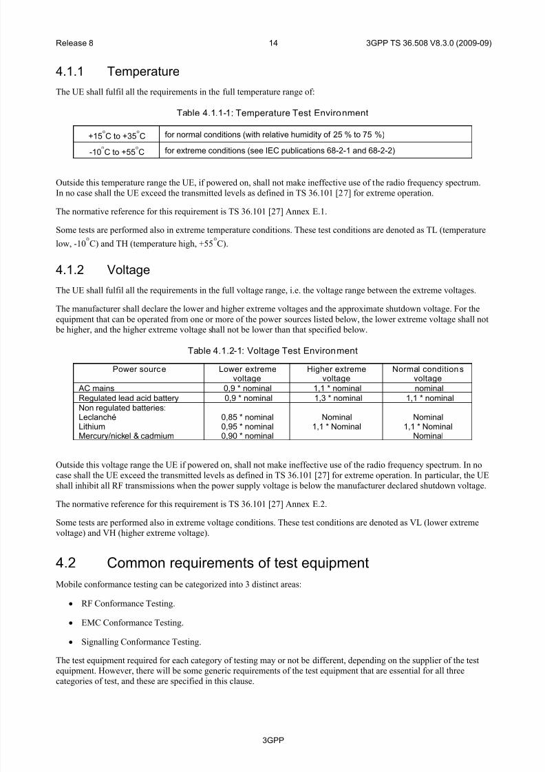
The UE shall fulfil all the requirements in the full temperature range of:
Table 4.1.1-1: Temperature Test Environment
+15°C to +35°C for normal conditions (with relative humidity of 25 % to 75 %)
-10°C to +55°C for extreme conditions (see IEC publications 68-2-1 and 68-2-2)
Outside this temperature range the UE, if powered on, shall not make ineffective use of the radio frequency spectrum.In no case shall the UE exceed the transmitted levels as defined in TS 36.101 [27] for extreme operation.
The normative reference for this requirement is TS 36.101 [27] Annex E.1.
Some tests are performed also in extreme temperature conditions. These test conditions are denoted as TL (temperature
low, -10°C) and TH (temperature high, +55°C).
4.1.2 Voltage
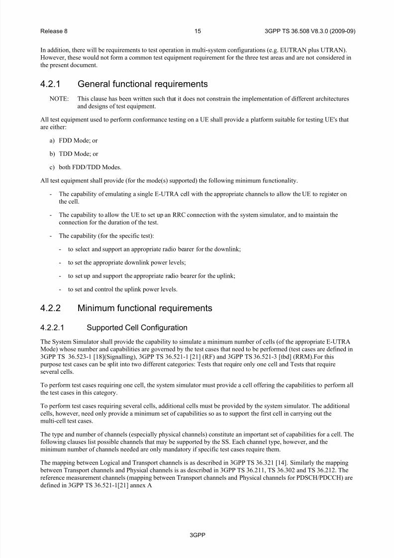
The UE shall fulfil all the requirements in the full voltage range, i.e. the voltage range between the extreme voltages.
The manufacturer shall declare the lower and higher extreme voltages and the approximate shutdown voltage. For theequipment that can be operated from one or more of the power sources listed below, the lower extreme voltage shall not
be higher, and the higher extreme voltage shall not be lower than that specified below.
Table 4.1.2-1: Voltage Test Envi ronment
Power source Lower extremevoltage
Higher extremevoltage
Normal conditionsvoltage
AC mains 0,9 * nominal 1,1 * nominal nominal
Regulated lead acid battery 0,9 * nominal 1,3 * nominal 1,1 * nominalNon regulated batteries:LeclanchéLithiumMercury/nickel & cadmium
0,85 * nominal0,95 * nominal0,90 * nominal
Nominal1,1 * Nominal
Nominal1,1 * Nominal
Nominal
Outside this voltage range the UE if powered on, shall not make ineffective use of the radio frequency spectrum. In nocase shall the UE exceed the transmitted levels as defined in TS 36.101 [27] for extreme operation. In particular, the UEshall inhibit all RF transmissions when the power supply voltage is below the manufacturer declared shutdown voltage.
The normative reference for this requirement is TS 36.101 [27] Annex E.2.
Some tests are performed also in extreme voltage conditions. These test conditions are denoted as VL (lower extreme
voltage) and VH (higher extreme voltage).
4.2 Common requirements of test equipment
Mobile conformance testing can be categorized into 3 distinct areas:
• RF Conformance Testing.
• EMC Conformance Testing.
• Signalling Conformance Testing.
The test equipment required for each category of testing may or not be different, depending on the supplier of the test
equipment. However, there will be some generic requirements of the test equipment that are essential for all threecategories of test, and these are specified in this clause.
7/15/2019 Lte Sib Info
http://slidepdf.com/reader/full/lte-sib-info 15/187
3GPP
3GPP TS 36.508 V8.3.0 (2009-09)15Release 8
In addition, there will be requirements to test operation in multi-system configurations (e.g. EUTRAN plus UTRAN).However, these would not form a common test equipment requirement for the three test areas and are not considered inthe present document.
4.2.1 General functional requirements
NOTE: This clause has been written such that it does not constrain the implementation of different architecturesand designs of test equipment.
All test equipment used to perform conformance testing on a UE shall provide a platform suitable for testing UE's thatare either:
a) FDD Mode; or
b) TDD Mode; or
c) both FDD/TDD Modes.
All test equipment shall provide (for the mode(s) supported) the following minimum functionality.
- The capability of emulating a single E-UTRA cell with the appropriate channels to allow the UE to register onthe cell.
- The capability to allow the UE to set up an RRC connection with the system simulator, and to maintain theconnection for the duration of the test.
- The capability (for the specific test):
- to select and support an appropriate radio bearer for the downlink;
- to set the appropriate downlink power levels;
- to set up and support the appropriate radio bearer for the uplink;
- to set and control the uplink power levels.
4.2.2 Minimum functional requirements
4.2.2.1 Supported Cell Configuration
The System Simulator shall provide the capability to simulate a minimum number of cells (of the appropriate E-UTRAMode) whose number and capabilities are governed by the test cases that need to be performed (test cases are defined in3GPP TS 36.523-1 [18](Signalling), 3GPP TS 36.521-1 [21] (RF) and 3GPP TS 36.521-3 [tbd] (RRM).For this
purpose test cases can be split into two different categories: Tests that require only one cell and Tests that requireseveral cells.
To perform test cases requiring one cell, the system simulator must provide a cell offering the capabilities to perform allthe test cases in this category.
To perform test cases requiring several cells, additional cells must be provided by the system simulator. The additionalcells, however, need only provide a minimum set of capabilities so as to support the first cell in carrying out themulti-cell test cases.
The type and number of channels (especially physical channels) constitute an important set of capabilities for a cell. Thefollowing clauses list possible channels that may be supported by the SS. Each channel type, however, and theminimum number of channels needed are only mandatory if specific test cases require them.
The mapping between Logical and Transport channels is as described in 3GPP TS 36.321 [14]. Similarly the mapping between Transport channels and Physical channels is as described in 3GPP TS 36.211, TS 36.302 and TS 36.212. Thereference measurement channels (mapping between Transport channels and Physical channels for PDSCH/PDCCH) are
defined in 3GPP TS 36.521-1[21] annex A

7/15/2019 Lte Sib Info
http://slidepdf.com/reader/full/lte-sib-info 16/187
3GPP
3GPP TS 36.508 V8.3.0 (2009-09)16Release 8
4.2.2.1.1 Supported Channels
4.2.2.1.1.1 Logical channels
Logical channel Minimum number Comments
BCCH 1
CCCH 1DCCH 2
PCCH 1
DTCH n <FFS> Depending on SS's support for RB service testing(See clause 12 of 3GPP TS 36.523-1 [?]
4.2.2.1.1.2 Transport channels
Transport channel Minimum number Comments
BCH 1
PCH 1
RACH 1
DL-SCH n <FFS>UL-SCH n <FFS>
4.2.2.1.1.3 Physical channels
Physical channel Minimum number Comments
PBCH 1 Physical Broadcast Channel
PCFICH 1 The physical control format indicator channel carries information about thenumber of OFDM symbols used for transmission of PDCCHs in a subframe
PDCCH 1 The physical downlink control channel carries scheduling assignments andother control information.
PDSCH 1 Physical Downlink Shared Channel
PHICH [1] The PHICH carries the hybrid-ARQ ACK/NAK
PUCCH 1 The physical uplink control channel carries uplink control information
PUSCH 1 Physical Uplink Shared Channel
PRACH 1 Physical Random Access Channel
4.2.2.1.1.4 Physical signals
Physical signal Minimum number Comments
Demodulationreference signal
NA UL
SoundingReference signal
NA UL TBD, if applicable
Cell-specificReference Signal
NA DL
UE-specificreference signal
NA DL
Primarysynchronisationsignal
NA DL
Secondarysynchronisationsignal
NA DL
7/15/2019 Lte Sib Info
http://slidepdf.com/reader/full/lte-sib-info 17/187
3GPP
3GPP TS 36.508 V8.3.0 (2009-09)17Release 8
4.2.2.2 Support of Tcell timing offset
The timing offset in terms of frame start timing between any pair of TDD cells shall be < [3us]. For FDD cells there isno such restriction.
4.3 Reference test conditionsThis clause contains the reference test conditions, which apply to all test cases unless otherwise specified.
4.3.1 Test frequencies
The test frequencies are based on the E-UTRA frequency bands defined in the core specifications.
The raster spacing is 100 KHz.
E-UTRA/FDD is designed to operate in paired bands of 3GPP TS 36.101 [27]. The reference test frequencies for the RFand Signalling test environment for each of the 14 operating bands are defined in sub clause 4.3.1.1.
E-UTRA/TDD is designed to operate in unpaired bands of 3GPP TS 36.101 [27]. The reference test frequencies for theRF and Signalling test environment for each of the 8 operating bands are defined in sub clause 4.3.1.2.
NOTE: For Signalling testing, E-UTRA frequency to be tested is mid range and E-UTRA channel bandwidth to betested is 5MHz for all operating bands for all test cases as the default configuration.
NOTE: For RF testing, E-UTRA frequencies to be tested are low range, mid range and high range for all supportedoperating bands by default. E-UTRA channel bandwidths to be tested are lowest bandwidth, 5MHz
bandwidth and highest bandwidth for all supported operating bands by default. Actual test configurationsare specified case by case and stated in test case itself as the initial conditions.
NOTE: The lowest bandwidth, 5MHz bandwidth and highest bandwidth are selected from the combined table whichincludes nominal and additional channel bandwidth.
NOTE: In the case 5MHz bandwidth is not supported by the UE, E-UTRA channel bandwidth to be tested are onlylowest bandwidth and highest bandwidth.
NOTE: If channel bandwidth to be tested is equal to the lowest or highest channel bandwidth, then the same channel bandwidth is not required to be tested twice.
4.3.1.1 FDD Mode Test frequencies
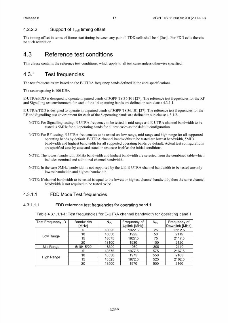
4.3.1.1.1 FDD reference test frequencies for operating band 1
Table 4.3.1.1.1-1: Test f requencies for E-UTRA channel bandwidth for operating band 1
Test Frequency ID Bandwidth[MHz]
NUL Frequency of Uplink [MHz]
NDL Frequency of Downlink [MHz]
5 18025 1922.5 25 2112.5
10 18050 1925 50 2115
15 18075 1927.5 75 2117.5Low Range
20 18100 1930 100 2120
Mid Range 5/10/15/20 18300 1950 300 2140
5 18575 1977.5 575 2167.5
10 18550 1975 550 2165
15 18525 1972.5 525 2162.5High Range
20 18500 1970 500 2160
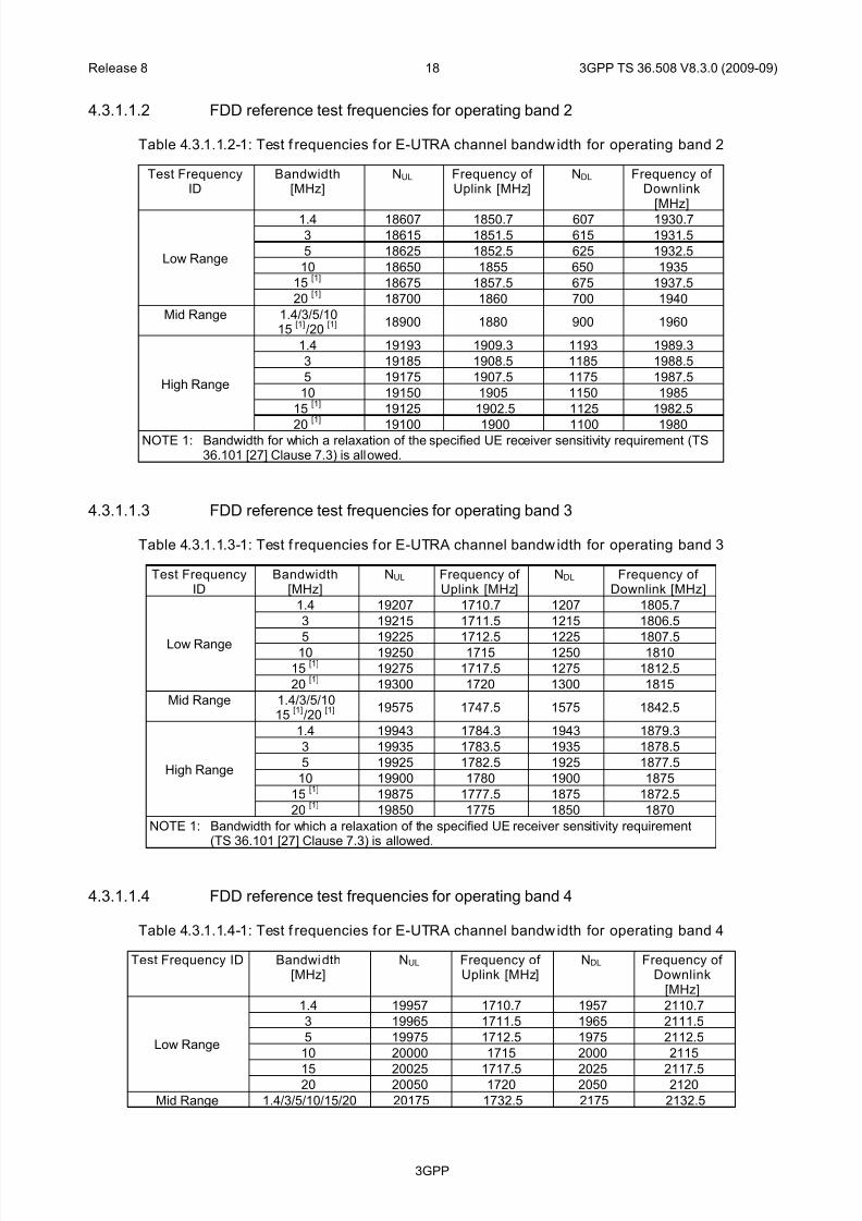
7/15/2019 Lte Sib Info
http://slidepdf.com/reader/full/lte-sib-info 18/187
3GPP
3GPP TS 36.508 V8.3.0 (2009-09)18Release 8
4.3.1.1.2 FDD reference test frequencies for operating band 2
Table 4.3.1.1.2-1: Test f requencies for E-UTRA channel bandwidth for operating band 2
Test FrequencyID
Bandwidth[MHz]
NUL Frequency of Uplink [MHz]
NDL Frequency of Downlink
[MHz]
1.4 18607 1850.7 607 1930.7
3 18615 1851.5 615 1931.5
5 18625 1852.5 625 1932.5
10 18650 1855 650 1935
15[1]
18675 1857.5 675 1937.5
Low Range
20[1]
18700 1860 700 1940
Mid Range 1.4/3/5/1015
[1]/20
[1]
18900 1880 900 1960
1.4 19193 1909.3 1193 1989.3
3 19185 1908.5 1185 1988.5
5 19175 1907.5 1175 1987.5
10 19150 1905 1150 1985
15[1]
19125 1902.5 1125 1982.5
High Range
20[1]
19100 1900 1100 1980NOTE 1: Bandwidth for which a relaxation of the specified UE receiver sensitivity requirement (TS
36.101 [27] Clause 7.3) is allowed.
4.3.1.1.3 FDD reference test frequencies for operating band 3
Table 4.3.1.1.3-1: Test f requencies for E-UTRA channel bandwidth for operating band 3
Test FrequencyID
Bandwidth[MHz]
NUL Frequency of Uplink [MHz]
NDL Frequency of Downlink [MHz]
1.4 19207 1710.7 1207 1805.7
3 19215 1711.5 1215 1806.5
5 19225 1712.5 1225 1807.510 19250 1715 1250 1810
15[1]
19275 1717.5 1275 1812.5
Low Range
20[1]
19300 1720 1300 1815
Mid Range 1.4/3/5/1015
[1]/20
[1]
19575 1747.5 1575 1842.5
1.4 19943 1784.3 1943 1879.3
3 19935 1783.5 1935 1878.5
5 19925 1782.5 1925 1877.5
10 19900 1780 1900 1875
15[1]
19875 1777.5 1875 1872.5
High Range
20[1]
19850 1775 1850 1870
NOTE 1: Bandwidth for which a relaxation of the specified UE receiver sensitivity requirement(TS 36.101 [27] Clause 7.3) is allowed.
4.3.1.1.4 FDD reference test frequencies for operating band 4
Table 4.3.1.1.4-1: Test f requencies for E-UTRA channel bandwidth for operating band 4
Test Frequency ID Bandwidth[MHz]
NUL Frequency of Uplink [MHz]
NDL Frequency of Downlink
[MHz]
1.4 19957 1710.7 1957 2110.7
3 19965 1711.5 1965 2111.5
5 19975 1712.5 1975 2112.5
10 20000 1715 2000 2115
15 20025 1717.5 2025 2117.5
Low Range
20 20050 1720 2050 2120
Mid Range 1.4/3/5/10/15/20 20175 1732.5 2175 2132.5
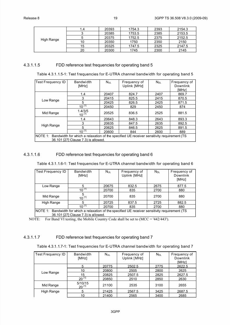
7/15/2019 Lte Sib Info
http://slidepdf.com/reader/full/lte-sib-info 19/187
3GPP
3GPP TS 36.508 V8.3.0 (2009-09)19Release 8
1.4 20393 1754.3 2393 2154.3
3 20385 1753.5 2385 2153.5
5 20375 1752.5 2375 2152.5
10 20350 1750 2350 2150
15 20325 1747.5 2325 2147.5
High Range
20 20300 1745 2300 2145
4.3.1.1.5 FDD reference test frequencies for operating band 5
Table 4.3.1.1.5-1: Test f requencies for E-UTRA channel bandwidth for operating band 5
Test Frequency ID Bandwidth[MHz]
NUL Frequency of Uplink [MHz]
NDL Frequency of Downlink
[MHz]
1.4 20407 824.7 2407 869.7
3 20415 825.5 2415 870.5
5 20425 826.5 2425 871.5Low Range
10[1]
20450 829 2450 874
Mid Range1.4/3/510 [1] 20525 836.5 2525 881.5
1.4 20643 848.3 2643 893.3
3 20635 847.5 2635 892.5
5 20625 846.5 2625 891.5High Range
10[1]
20600 844 2600 889
NOTE 1: Bandwidth for which a relaxation of the specified UE receiver sensitivity requirement (TS36.101 [27] Clause 7.3) is allowed.
4.3.1.1.6 FDD reference test frequencies for operating band 6
Table 4.3.1.1.6-1: Test f requencies for E-UTRA channel bandwidth for operating band 6
Test Frequency ID Bandwidth[MHz]
NUL Frequency of Uplink [MHz]
NDL Frequency of Downlink
[MHz]
5 20675 832.5 2675 877.5Low Range
10[1]
20700 835 2700 880
Mid Range5
10[1]
20700 835 2700 880
5 20725 837.5 2725 882.5High Range
10[1]
20700 835 2700 880NOTE 1: Bandwidth for which a relaxation of the specified UE receiver sensitivity requirement (TS
36.101 [27] Clause 7.3) is allowed.
NOTE: For Band VI testing, the Mobile Country Code shall be set to (MCC = '442/443').
4.3.1.1.7 FDD reference test frequencies for operating band 7
Table 4.3.1.1.7-1: Test f requencies for E-UTRA channel bandwidth for operating band 7
Test Frequency ID Bandwidth[MHz]
NUL Frequency of Uplink [MHz]
NDL Frequency of Downlink
[MHz]
5 20775 2502.5 2775 2622.5
10 20800 2505 2800 2625
15 20825 2507.5 2825 2627.5Low Range
20[1]
20850 2510 2850 2630
Mid Range 5/10/1520
[1]
21100 2535 3100 2655
5 21425 2567.5 3425 2687.5High Range
10 21400 2565 3400 2685

7/15/2019 Lte Sib Info
http://slidepdf.com/reader/full/lte-sib-info 20/187
3GPP
3GPP TS 36.508 V8.3.0 (2009-09)20Release 8
15 21375 2562.5 3375 2682.5
20[1]
21350 2560 3350 2680NOTE 1: Bandwidth for which a relaxation of the specified UE receiver sensitivity requirement (TS
36.101 [27] Clause 7.3) is allowed.
4.3.1.1.8 FDD reference test frequencies for operating band 8
Table 4.3.1.1.8-1: Test f requencies for E-UTRA channel bandwidth for operating band 8
Test Frequency ID Bandwidth[MHz]
NUL Frequency of Uplink [MHz]
NDL Frequency of Downlink
[MHz]
1.4 21457 880.7 3457 925.7
3 21465 881.5 3465 926.5
5 21475 882.5 3475 927.5Low Range
10[1]
21500 885 3500 930
Mid Range1.4/3/510
[1]
21625 897.5 3625 942.5
1.4 21793 914.3 3793 959.3
3 21785 913.5 3785 958.5
5 21775 912.5 3775 957.5High Range
10[1]
21750 910 3750 955
NOTE 1: Bandwidth for which a relaxation of the specified UE receiver sensitivity requirement (TS36.101 [27] Clause 7.3) is allowed.
4.3.1.1.9 FDD reference test frequencies for operating band 9
Table 4.3.1.1.9-1: Test f requencies for E-UTRA channel bandwidth for operating band 9
Test Frequency ID Bandwidth[MHz]
NUL Frequency of Uplink [MHz]
NDL Frequency of Downlink
[MHz]5 21825 1752.4 3825 1847.4
10 21850 1754.9 3850 1849.9
15[1]
21875 1757.4 3875 1852.4Low Range
20[1]
21900 1759.9 3900 1854.9
Mid Range5/10
15[1]
/20[1]
21975 1767.4 3975 1862.4
5 22125 1782.4 4125 1877.4
10 22100 1779.9 4100 1874.9
15[1]
22075 1777.4 4075 1872.4High Range
20[1]
22050 1774.9 4050 1869.9
NOTE 1: Bandwidth for which a relaxation of the specified UE receiver sensitivity requirement (TS36.101 [27] Clause 7.3) is allowed.
4.3.1.1.10 FDD reference test frequencies for operating band 10
Table 4.3.1.1.10-1: Test f requencies for E-UTRA channel bandwidth for operating band 10
Test FrequencyID
Bandwidth[MHz]
NUL Frequency of Uplink [MHz]
NDL Frequency of Downlink [MHz]
5 22175 1712.5 4175 2112.5
10 22200 1715 4200 2115
15 22225 1717.5 4225 2117.5Low Range
20 22250 1720 4250 2120
Mid Range 5/10/15/20 22450 1740 4450 2140
5 22725 1767.5 4725 2167.510 22700 1765 4700 2165
15 22675 1762.5 4675 2162.5High Range
20 22650 1760 4650 2160
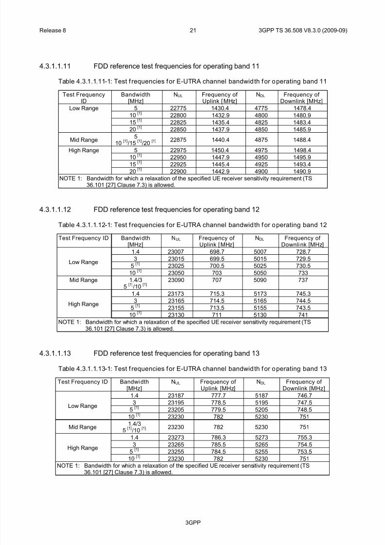
7/15/2019 Lte Sib Info
http://slidepdf.com/reader/full/lte-sib-info 21/187
3GPP
3GPP TS 36.508 V8.3.0 (2009-09)21Release 8
4.3.1.1.11 FDD reference test frequencies for operating band 11
Table 4.3.1.1.11-1: Test f requencies for E-UTRA channel bandwidth for operating band 11
Test FrequencyID
Bandwidth[MHz]
NUL Frequency of Uplink [MHz]
NDL Frequency of Downlink [MHz]
5 22775 1430.4 4775 1478.4
10[1]
22800 1432.9 4800 1480.9
15[1]
22825 1435.4 4825 1483.4
Low Range
20[1]
22850 1437.9 4850 1485.9
Mid Range5
10[1]
/15[1]
/20[1]
22875 1440.4 4875 1488.4
5 22975 1450.4 4975 1498.4
10[1]
22950 1447.9 4950 1495.9
15[1]
22925 1445.4 4925 1493.4
High Range
20[1]
22900 1442.9 4900 1490.9
NOTE 1: Bandwidth for which a relaxation of the specified UE receiver sensitivity requirement (TS36.101 [27] Clause 7.3) is allowed.
4.3.1.1.12 FDD reference test frequencies for operating band 12
Table 4.3.1.1.12-1: Test f requencies for E-UTRA channel bandwidth for operating band 12
Test Frequency ID Bandwidth[MHz]
NUL Frequency of Uplink [MHz]
NDL Frequency of Downlink [MHz]
1.4 23007 698.7 5007 728.7
3 23015 699.5 5015 729.5
5[1]
23025 700.5 5025 730.5Low Range
10[1]
23050 703 5050 733
Mid Range 1.4/35 [1]/10 [1]
23090 707 5090 737
1.4 23173 715.3 5173 745.3
3 23165 714.5 5165 744.5
5[1]
23155 713.5 5155 743.5High Range
10[1]
23130 711 5130 741
NOTE 1: Bandwidth for which a relaxation of the specified UE receiver sensitivity requirement (TS36.101 [27] Clause 7.3) is allowed.
4.3.1.1.13 FDD reference test frequencies for operating band 13
Table 4.3.1.1.13-1: Test f requencies for E-UTRA channel bandwidth for operating band 13
Test Frequency ID Bandwidth[MHz]
NUL Frequency of Uplink [MHz]
NDL Frequency of Downlink [MHz]
1.4 23187 777.7 5187 746.7
3 23195 778.5 5195 747.5
5[1]
23205 779.5 5205 748.5Low Range
10[1]
23230 782 5230 751
Mid Range1.4/3
5[1]
/10[1]
23230 782 5230 751
1.4 23273 786.3 5273 755.3
3 23265 785.5 5265 754.5
5[1]
23255 784.5 5255 753.5High Range
10[1]
23230 782 5230 751
NOTE 1: Bandwidth for which a relaxation of the specified UE receiver sensitivity requirement (TS
36.101 [27] Clause 7.3) is allowed.
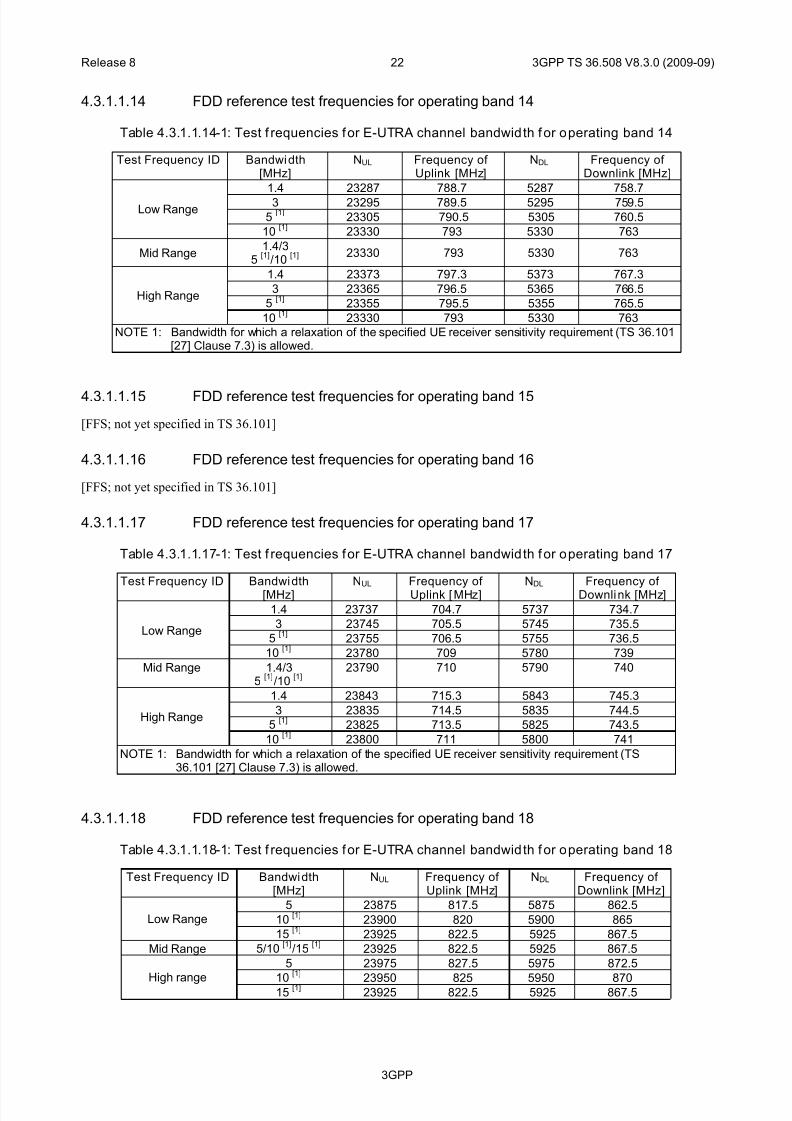
7/15/2019 Lte Sib Info
http://slidepdf.com/reader/full/lte-sib-info 22/187
3GPP
3GPP TS 36.508 V8.3.0 (2009-09)22Release 8
4.3.1.1.14 FDD reference test frequencies for operating band 14
Table 4.3.1.1.14-1: Test f requencies for E-UTRA channel bandwidth for operating band 14
Test Frequency ID Bandwidth[MHz]
NUL Frequency of Uplink [MHz]
NDL Frequency of Downlink [MHz]
1.4 23287 788.7 5287 758.7
3 23295 789.5 5295 759.5
5[1]
23305 790.5 5305 760.5Low Range
10[1]
23330 793 5330 763
Mid Range1.4/3
5[1]
/10[1]
23330 793 5330 763
1.4 23373 797.3 5373 767.3
3 23365 796.5 5365 766.5
5[1]
23355 795.5 5355 765.5High Range
10[1]
23330 793 5330 763
NOTE 1: Bandwidth for which a relaxation of the specified UE receiver sensitivity requirement (TS 36.101[27] Clause 7.3) is allowed.
4.3.1.1.15 FDD reference test frequencies for operating band 15
[FFS; not yet specified in TS 36.101]
4.3.1.1.16 FDD reference test frequencies for operating band 16
[FFS; not yet specified in TS 36.101]
4.3.1.1.17 FDD reference test frequencies for operating band 17
Table 4.3.1.1.17-1: Test f requencies for E-UTRA channel bandwidth for operating band 17
Test Frequency ID Bandwidth[MHz] NUL Frequency of Uplink [MHz] NDL Frequency of Downlink [MHz]
1.4 23737 704.7 5737 734.7
3 23745 705.5 5745 735.5
5[1]
23755 706.5 5755 736.5Low Range
10[1]
23780 709 5780 739
Mid Range 1.4/35
[1]/10
[1]
23790 710 5790 740
1.4 23843 715.3 5843 745.3
3 23835 714.5 5835 744.5
5[1]
23825 713.5 5825 743.5High Range
10[1]
23800 711 5800 741
NOTE 1: Bandwidth for which a relaxation of the specified UE receiver sensitivity requirement (TS36.101 [27] Clause 7.3) is allowed.
4.3.1.1.18 FDD reference test frequencies for operating band 18
Table 4.3.1.1.18-1: Test f requencies for E-UTRA channel bandwidth for operating band 18
Test Frequency ID Bandwidth[MHz]
NUL Frequency of Uplink [MHz]
NDL Frequency of Downlink [MHz]
5 23875 817.5 5875 862.5
10[1]
23900 820 5900 865Low Range
15[1]
23925 822.5 5925 867.5
Mid Range 5/10[1]
/15[1]
23925 822.5 5925 867.5
5 23975 827.5 5975 872.5
10 [1] 23950 825 5950 870High range15
[1] 23925 822.5 5925 867.5
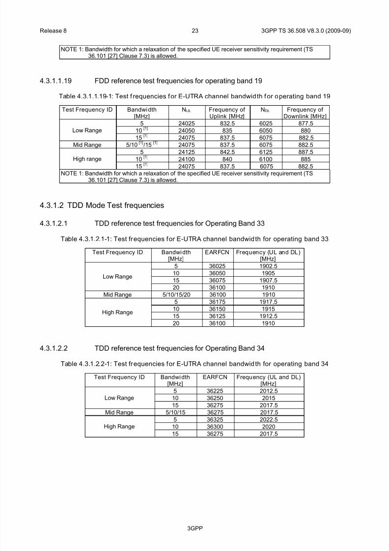
7/15/2019 Lte Sib Info
http://slidepdf.com/reader/full/lte-sib-info 23/187
3GPP
3GPP TS 36.508 V8.3.0 (2009-09)23Release 8
NOTE 1: Bandwidth for which a relaxation of the specified UE receiver sensitivity requirement (TS36.101 [27] Clause 7.3) is allowed.
4.3.1.1.19 FDD reference test frequencies for operating band 19
Table 4.3.1.1.19-1: Test f requencies for E-UTRA channel bandwidth for operating band 19
Test Frequency ID Bandwidth[MHz]
NUL Frequency of Uplink [MHz]
NDL Frequency of Downlink [MHz]
5 24025 832.5 6025 877.5
10[1]
24050 835 6050 880Low Range
15[1]
24075 837.5 6075 882.5
Mid Range 5/10[1]
/15[1]
24075 837.5 6075 882.5
5 24125 842.5 6125 887.5
10[1]
24100 840 6100 885High range
15[1]
24075 837.5 6075 882.5
NOTE 1: Bandwidth for which a relaxation of the specified UE receiver sensitivity requirement (TS36.101 [27] Clause 7.3) is allowed.
4.3.1.2 TDD Mode Test frequencies
4.3.1.2.1 TDD reference test frequencies for Operating Band 33
Table 4.3.1.2.1-1: Test frequencies for E-UTRA channel bandwidth for operating band 33
Test Frequency ID Bandwidth[MHz]
EARFCN Frequency (UL and DL)[MHz]
5 36025 1902.5
10 36050 1905
15 36075 1907.5Low Range
20 36100 1910Mid Range 5/10/15/20 36100 1910
5 36175 1917.5
10 36150 1915
15 36125 1912.5High Range
20 36100 1910
4.3.1.2.2 TDD reference test frequencies for Operating Band 34
Table 4.3.1.2.2-1: Test frequencies for E-UTRA channel bandwidth for operating band 34
Test Frequency ID Bandwidth
[MHz]
EARFCN Frequency (UL and DL)
[MHz]5 36225 2012.5
10 36250 2015Low Range
15 36275 2017.5
Mid Range 5/10/15 36275 2017.5
5 36325 2022.5
10 36300 2020High Range
15 36275 2017.5
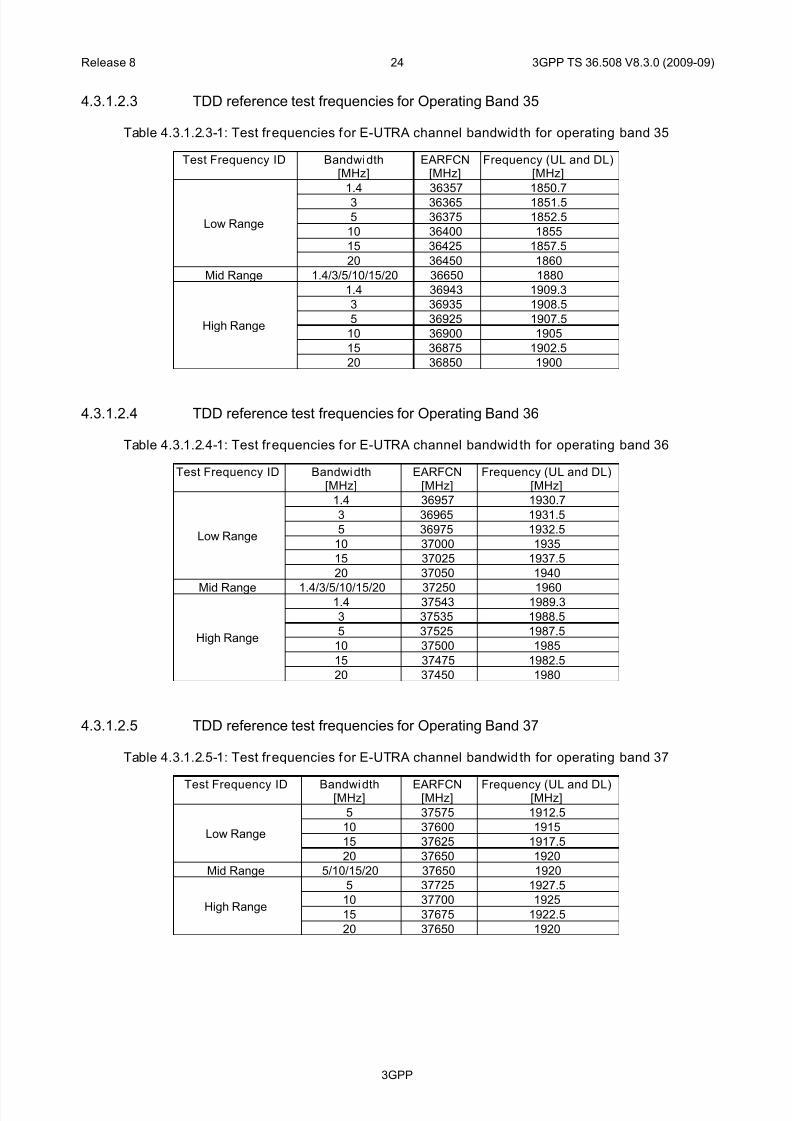
7/15/2019 Lte Sib Info
http://slidepdf.com/reader/full/lte-sib-info 24/187
3GPP
3GPP TS 36.508 V8.3.0 (2009-09)24Release 8
4.3.1.2.3 TDD reference test frequencies for Operating Band 35
Table 4.3.1.2.3-1: Test frequencies for E-UTRA channel bandwidth for operating band 35
Test Frequency ID Bandwidth[MHz]
EARFCN[MHz]
Frequency (UL and DL)[MHz]
1.4 36357 1850.7
3 36365 1851.5
5 36375 1852.5
10 36400 1855
15 36425 1857.5
Low Range
20 36450 1860
Mid Range 1.4/3/5/10/15/20 36650 1880
1.4 36943 1909.3
3 36935 1908.5
5 36925 1907.5
10 36900 1905
15 36875 1902.5
High Range
20 36850 1900
4.3.1.2.4 TDD reference test frequencies for Operating Band 36
Table 4.3.1.2.4-1: Test frequencies for E-UTRA channel bandwidth for operating band 36
Test Frequency ID Bandwidth[MHz]
EARFCN[MHz]
Frequency (UL and DL)[MHz]
1.4 36957 1930.7
3 36965 1931.5
5 36975 1932.5
10 37000 1935
15 37025 1937.5
Low Range
20 37050 1940
Mid Range 1.4/3/5/10/15/20 37250 19601.4 37543 1989.3
3 37535 1988.5
5 37525 1987.5
10 37500 1985
15 37475 1982.5
High Range
20 37450 1980
4.3.1.2.5 TDD reference test frequencies for Operating Band 37
Table 4.3.1.2.5-1: Test frequencies for E-UTRA channel bandwidth for operating band 37
Test Frequency ID Bandwidth[MHz]
EARFCN[MHz]
Frequency (UL and DL)[MHz]
5 37575 1912.5
10 37600 1915
15 37625 1917.5Low Range
20 37650 1920
Mid Range 5/10/15/20 37650 1920
5 37725 1927.5
10 37700 1925
15 37675 1922.5High Range
20 37650 1920
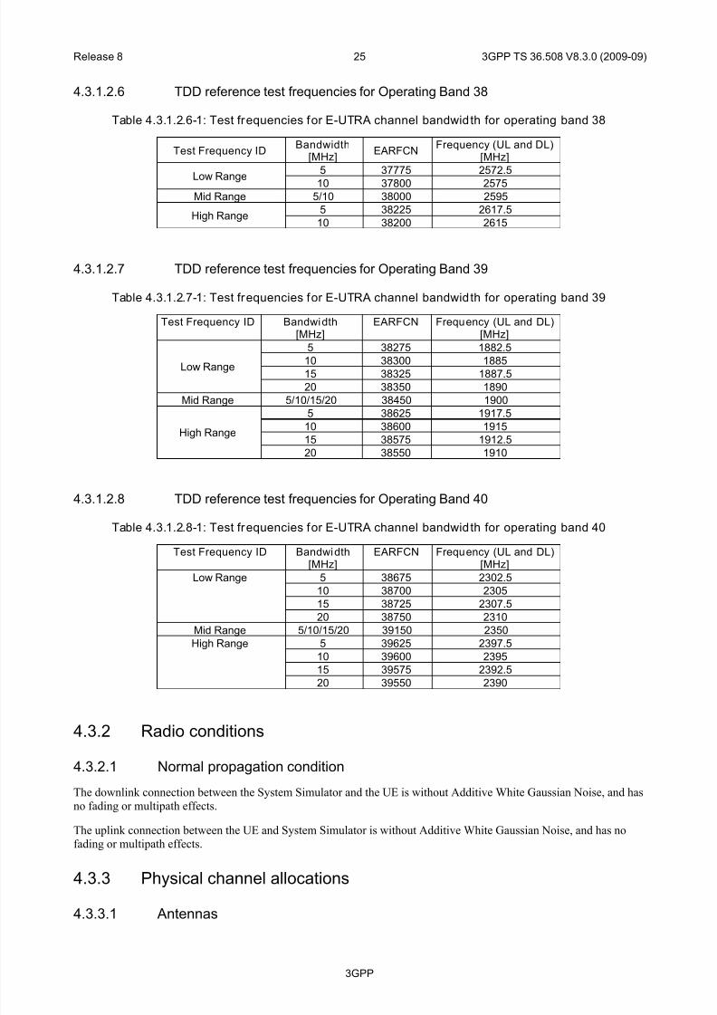
7/15/2019 Lte Sib Info
http://slidepdf.com/reader/full/lte-sib-info 25/187
3GPP
3GPP TS 36.508 V8.3.0 (2009-09)25Release 8
4.3.1.2.6 TDD reference test frequencies for Operating Band 38
Table 4.3.1.2.6-1: Test frequencies for E-UTRA channel bandwidth for operating band 38
Test Frequency IDBandwidth
[MHz]EARFCN
Frequency (UL and DL)[MHz]
5 37775 2572.5Low Range 10 37800 2575
Mid Range 5/10 38000 2595
5 38225 2617.5High Range
10 38200 2615
4.3.1.2.7 TDD reference test frequencies for Operating Band 39
Table 4.3.1.2.7-1: Test frequencies for E-UTRA channel bandwidth for operating band 39
Test Frequency ID Bandwidth[MHz]
EARFCN Frequency (UL and DL)[MHz]
5 38275 1882.510 38300 1885
15 38325 1887.5Low Range
20 38350 1890
Mid Range 5/10/15/20 38450 1900
5 38625 1917.5
10 38600 1915
15 38575 1912.5High Range
20 38550 1910
4.3.1.2.8 TDD reference test frequencies for Operating Band 40
Table 4.3.1.2.8-1: Test frequencies for E-UTRA channel bandwidth for operating band 40
Test Frequency ID Bandwidth[MHz]
EARFCN Frequency (UL and DL)[MHz]
5 38675 2302.5
10 38700 2305
15 38725 2307.5
Low Range
20 38750 2310
Mid Range 5/10/15/20 39150 2350
5 39625 2397.5
10 39600 2395
15 39575 2392.5
High Range
20 39550 2390
4.3.2 Radio conditions
4.3.2.1 Normal propagation condition
The downlink connection between the System Simulator and the UE is without Additive White Gaussian Noise, and hasno fading or multipath effects.
The uplink connection between the UE and System Simulator is without Additive White Gaussian Noise, and has nofading or multipath effects.
4.3.3 Physical channel allocations
4.3.3.1 Antennas
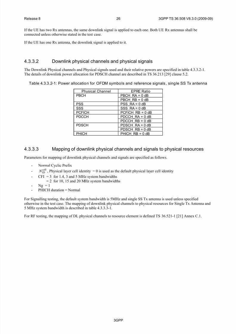
7/15/2019 Lte Sib Info
http://slidepdf.com/reader/full/lte-sib-info 26/187
3GPP
3GPP TS 36.508 V8.3.0 (2009-09)26Release 8
If the UE has two Rx antennas, the same downlink signal is applied to each one. Both UE Rx antennas shall beconnected unless otherwise stated in the test case.
If the UE has one Rx antenna, the downlink signal is applied to it.
4.3.3.2 Downlink physical channels and physical signals
The Downlink Physical channels and Physical signals used and their relative powers are specified in table 4.3.3.2-1.The details of downlink power allocation for PDSCH channel are described in TS 36.213 [29] clause 5.2.
Table 4.3.3.2-1: Power allocation for OFDM symbols and reference signals, sing le SS Tx antenna
Physical Channel EPRE Ratio
PBCH_RA = 0 dBPBCH
PBCH_RB = 0 dB
PSS PSS_RA = 0 dB
SSS SSS_RA = 0 dB
PCFICH PCFICH_RB = 0 dB
PDCCH_RA = 0 dBPDCCHPDCCH_RB = 0 dB
PDSCH_RA = 0 dBPDSCH
PDSCH_RB = 0 dB
PHICH PHICH_RB = 0 dB
4.3.3.3 Mapping of downlink physical channels and signals to physical resources
Parameters for mapping of downlink physical channels and signals are specified as follows.
- Normal Cyclic Prefix
- cellID N , Physical layer cell identity = 0 is used as the default physical layer cell identity
- CFI = 3 for 1.4, 3 and 5 MHz system bandwidths= 2 for 10, 15 and 20 MHz system bandwidths
- Ng = 1- PHICH duration = Normal
For Signalling testing, the default system bandwidth is 5MHz and single SS Tx antenna is used unless specifiedotherwise in the test case. The mapping of downlink physical channels to physical resources for Single Tx Antenna and5 MHz system bandwidth is described in table 4.3.3.3-1.
For RF testing, the mapping of DL physical channels to resource element is defined TS 36.521-1 [21] Annex C.1.
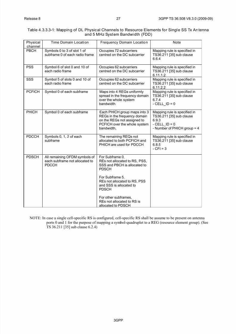
7/15/2019 Lte Sib Info
http://slidepdf.com/reader/full/lte-sib-info 27/187
3GPP
3GPP TS 36.508 V8.3.0 (2009-09)27Release 8
Table 4.3.3.3-1: Mapping of DL Physical Channels to Resource Elements for Single SS Tx Antennaand 5 MHz System Bandwidth (FDD)
Physicalchannel
Time Domain Location Frequency Domain Location Note
PBCH Symbols 0 to 3 of slot 1 of subframe 0 of each radio frame
Occupies 72 subcarrierscentred on the DC subcarrier
Mapping rule is specified inTS36.211 [35] sub clause
6.6.4
PSS Symbol 6 of slot 0 and 10 of each radio frame
Occupies 62 subcarrierscentred on the DC subcarrier
Mapping rule is specified inTS36.211 [35] sub clause6.11.1.2
SSS Symbol 5 of slots 0 and 10 of each radio frame
Occupies 62 subcarrierscentred on the DC subcarrier
Mapping rule is specified inTS36.211 [35] sub clause6.11.2.2
PCFICH Symbol 0 of each subframe Maps into 4 REGs uniformlyspread in the frequency domainover the whole systembandwidth.
Mapping rule is specified inTS36.211 [35] sub clause6.7.4- CELL_ID = 0
PHICH Symbol 0 of each subframe Each PHICH group maps into 3
REGs in the frequency domainon the REGs not assigned toPCFICH over the whole systembandwidth,
Mapping rule is specified in
TS36.211 [35] sub clause6.9.3- CELL_ID = 0- Number of PHICH group = 4
PDCCH Symbols 0, 1, 2 of eachsubframe
The remaining REQs notallocated to both PCFICH andPHICH are used for PDCCH
Mapping rule is specified inTS36.211 [35] sub clause6.8.5- CFI = 3
PDSCH All remaining OFDM symbols of each subframe not allocated toPDCCH
For Subframe 0,REs not allocated to RS, PSS,SSS and PBCH is allocated toPDSCH
For Subframe 5,REs not allocated to RS, PSSand SSS is allocated toPDSCH
For other subframes,REs not allocated to RS isallocated to PDSCH
NOTE: In case a single cell-specific RS is configured, cell-specific RS shall be assume to be present on antenna ports 0 and 1 for the purpose of mapping a symbol-quadruplet to a REG (resource element group). (SeeTS 36.211 [35] sub clause 6.2.4)

7/15/2019 Lte Sib Info
http://slidepdf.com/reader/full/lte-sib-info 28/187
3GPP
3GPP TS 36.508 V8.3.0 (2009-09)28Release 8
Table 4.3.3.3-2: Mapping of DL Physical Channels to Resource Elements for Single SS Tx Antennaand 5 MHz System Bandwidth (TDD)
Physicalchannel
Time Domain Location Frequency DomainLocation
Note
PBCH Symbols 0 to 3 of slot 1 of subframe 0 of each radio
frame
Occupies 72 subcarrierscentered on the DC subcarrier
Mapping rule is specified inTS36.211 [35] subclause
6.6.4
PSS Symbol 2 of slot 2 and 12 of each radio frame
Occupies 62 subcarrierscentered on the DC subcarrier
Mapping rule is specified inTS36.211 [35] subclause6.11.1.2
SSS Symbol 6 of slots 1 and 11 of each radio frame
Occupies 62 subcarrierscentered on the DC subcarrier
Mapping rule is specified inTS36.211 [35] subclause6.11.2.2
PCFICH Symbol 0 of each downlinksubframe and Specialsubframe
Maps into 4 REGs uniformlyspread in the frequencydomain over the wholesystem bandwidth.
Mapping rule is specified inTS36.211 [35] subclause6.7.4- CELL_ID = 0
PHICH Symbol 0 of each downlink
subframe and Specialsubframe
Each PHICH group maps into
3 REGs in the frequencydomain on the REGs notassigned to PCFICH over thewhole system bandwidth,
Mapping rule is specified in
TS36.211 [35] subclause6.9.3- CELL_ID = 0- Number of PHICH group =4
PDCCH Symbols 0, 1 of subframe 1, 6and Symbols 0, 1, 2 of other downlink subframes
The remaining REQs notallocated to both PCFICH andPHICH are used for PDCCH
Mapping rule is specified inTS36.211 [35] subclause6.8.5- CFI = 3
PDSCH All remaining OFDM symbolsof each downlink subframeand DwPTS not allocated to
PDCCH
For Subframe 0,REs not allocated to RS, SSSand PBCH is allocated to
PDSCH
For Subframe 5,REs not allocated to RS andSSS is allocated to PDSCH
For Subframe 1 and 6,REs not allocated to RS,PSS, GP and UpPTS isallocated to PDSCH
For other downlinksubframes,REs not allocated to RS isallocated to PDSCH
NOTE 1: In case a single cell-specific RS is configured, cell-specific RS shall be assume to be present on antenna ports 0 and 1 for the purpose of mapping a symbol-quadruplet to a REG (resource element group). (SeeTS 36.211 [35] subclause 6.2.4)
NOTE 2: In case the default TDD configuration for subframe assignment and special subframe patterns (seesubclause 4.6.3)4.3.3.4 Uplink physical channels and physical signals
[FFS].
4.3.3.5 Mapping of uplink physical channels and signals to physical resources
[FFS].
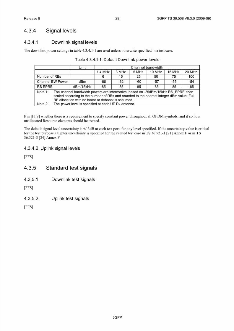
7/15/2019 Lte Sib Info
http://slidepdf.com/reader/full/lte-sib-info 29/187
3GPP
3GPP TS 36.508 V8.3.0 (2009-09)29Release 8
4.3.4 Signal levels
4.3.4.1 Downlink signal levels
The downlink power settings in table 4.3.4.1-1 are used unless otherwise specified in a test case.
Table 4.3.4.1-1: Default Downlink power levels
Unit Channel bandwidth
1.4 MHz 3 MHz 5 MHz 10 MHz 15 MHz 20 MHz
Number of RBs 6 15 25 50 75 100
Channel BW Power dBm -66 -62 -60 -57 -55 -54
RS EPRE dBm/15kHz -85 -85 -85 -85 -85 -85
Note 1: The channel bandwidth powers are informative, based on -85dBm/15kHz RS_EPRE, thenscaled according to the number of RBs and rounded to the nearest integer dBm value. FullRE allocation with no boost or deboost is assumed.
Note 2: The power level is specified at each UE Rx antenna.
It is [FFS] whether there is a requirement to specify constant power throughout all OFDM symbols, and if so howunallocated Resource elements should be treated.
The default signal level uncertainty is +/-3dB at each test port, for any level specified. If the uncertainty value is criticalfor the test purpose a tighter uncertainty is specified for the related test case in TS 36.521-1 [21] Annex F or in TS36.521-3 [34] Annex F
4.3.4.2 Uplink signal levels
[FFS]
4.3.5 Standard test signals
4.3.5.1 Downlink test signals
[FFS]
4.3.5.2 Uplink test signals
[FFS]

7/15/2019 Lte Sib Info
http://slidepdf.com/reader/full/lte-sib-info 30/187
3GPP
3GPP TS 36.508 V8.3.0 (2009-09)30Release 8
4.3.6 Physical layer parameters
4.3.6.1 Downlink physical layer parameters
4.3.6.1.1 Physical layer parameters for DCI format 0
Default physical layer parameters for DCI format 0 are specified in table 4.3.6.1.1-1.
Table 4.3.6.1.1-1: Phys ical layer parameters for DCI format 0
Parameter Value Value in binary
Flag for format 0/format 1A differentiation format 0 "0"
Hopping flag w/o Hopping "0"
Resource block assignment and hopping resource allocation depending on test parameters -
Modulation and coding scheme and redundancy version depending on test parameters -
New data indicator
Set for every datatransmission/retransmission
according to the rules specifiedin TS 36.321
-
TPC command for scheduled PUSCH 0 dB (accumulated TPC) "01"
Cyclic shift for DM RS 0 "000"
UL index (TDD only)
2 bits as defined in sections5.1.1.1 and 8 of TS 36.213. This
field is present only for TDDconfiguration 0
-
Downlink Assignment Index (TDD only)
2 bits as defined in Table 7.3-Xin TS 36.213. It represents the
total number of PDSCH
subframes with and withoutPDCCH and PDCCH indicating
downlink SPS release in thewindow. This field is presentonly for TDD configuration 1-6
-
CQI request w/o Aperiodic CQI "0"
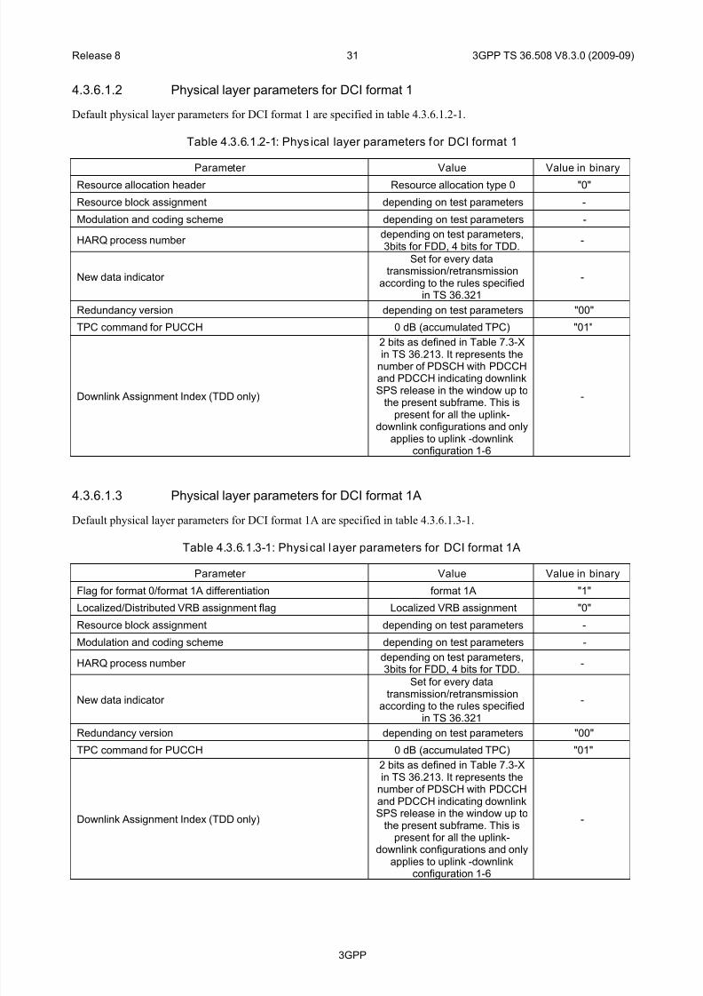
7/15/2019 Lte Sib Info
http://slidepdf.com/reader/full/lte-sib-info 31/187
3GPP
3GPP TS 36.508 V8.3.0 (2009-09)31Release 8
4.3.6.1.2 Physical layer parameters for DCI format 1
Default physical layer parameters for DCI format 1 are specified in table 4.3.6.1.2-1.
Table 4.3.6.1.2-1: Phys ical layer parameters for DCI format 1
Parameter Value Value in binaryResource allocation header Resource allocation type 0 "0"
Resource block assignment depending on test parameters -
Modulation and coding scheme depending on test parameters -
HARQ process number depending on test parameters,3bits for FDD, 4 bits for TDD.
-
New data indicator
Set for every datatransmission/retransmission
according to the rules specifiedin TS 36.321
-
Redundancy version depending on test parameters "00"
TPC command for PUCCH 0 dB (accumulated TPC) "01"
Downlink Assignment Index (TDD only)
2 bits as defined in Table 7.3-Xin TS 36.213. It represents thenumber of PDSCH with PDCCHand PDCCH indicating downlinkSPS release in the window up to
the present subframe. This ispresent for all the uplink-
downlink configurations and onlyapplies to uplink -downlink
configuration 1-6
-
4.3.6.1.3 Physical layer parameters for DCI format 1A
Default physical layer parameters for DCI format 1A are specified in table 4.3.6.1.3-1.
Table 4.3.6.1.3-1: Physical layer parameters for DCI format 1A
Parameter Value Value in binary
Flag for format 0/format 1A differentiation format 1A "1"
Localized/Distributed VRB assignment flag Localized VRB assignment "0"
Resource block assignment depending on test parameters -
Modulation and coding scheme depending on test parameters -
HARQ process number depending on test parameters,3bits for FDD, 4 bits for TDD.
-
New data indicator
Set for every data
transmission/retransmissionaccording to the rules specified
in TS 36.321
-
Redundancy version depending on test parameters "00"
TPC command for PUCCH 0 dB (accumulated TPC) "01"
Downlink Assignment Index (TDD only)
2 bits as defined in Table 7.3-Xin TS 36.213. It represents the
number of PDSCH with PDCCHand PDCCH indicating downlinkSPS release in the window up to
the present subframe. This ispresent for all the uplink-
downlink configurations and only
applies to uplink -downlinkconfiguration 1-6
-
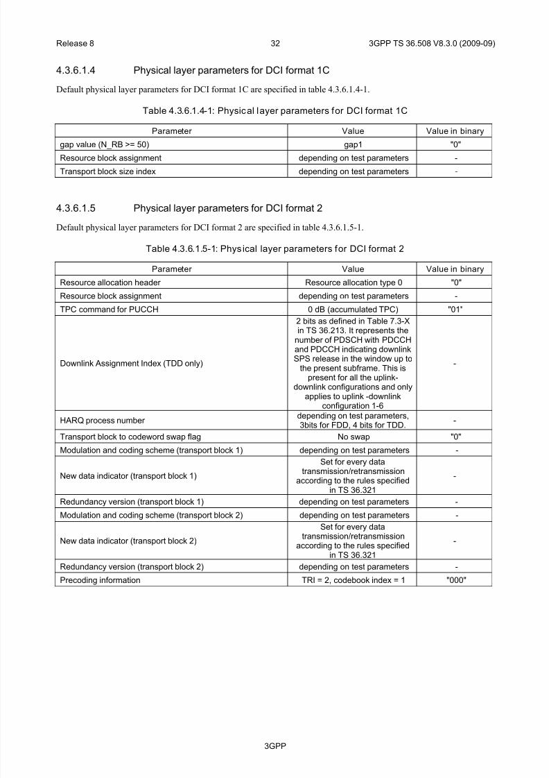
7/15/2019 Lte Sib Info
http://slidepdf.com/reader/full/lte-sib-info 32/187
3GPP
3GPP TS 36.508 V8.3.0 (2009-09)32Release 8
4.3.6.1.4 Physical layer parameters for DCI format 1C
Default physical layer parameters for DCI format 1C are specified in table 4.3.6.1.4-1.
Table 4.3.6.1.4-1: Physical layer parameters for DCI format 1C
Parameter Value Value in binarygap value (N_RB >= 50) gap1 "0"
Resource block assignment depending on test parameters -
Transport block size index depending on test parameters -
4.3.6.1.5 Physical layer parameters for DCI format 2
Default physical layer parameters for DCI format 2 are specified in table 4.3.6.1.5-1.
Table 4.3.6.1.5-1: Phys ical layer parameters for DCI format 2
Parameter Value Value in binaryResource allocation header Resource allocation type 0 "0"
Resource block assignment depending on test parameters -
TPC command for PUCCH 0 dB (accumulated TPC) "01"
Downlink Assignment Index (TDD only)
2 bits as defined in Table 7.3-Xin TS 36.213. It represents the
number of PDSCH with PDCCHand PDCCH indicating downlinkSPS release in the window up to
the present subframe. This ispresent for all the uplink-
downlink configurations and onlyapplies to uplink -downlink
configuration 1-6
-
HARQ process number depending on test parameters,3bits for FDD, 4 bits for TDD.
-
Transport block to codeword swap flag No swap "0"
Modulation and coding scheme (transport block 1) depending on test parameters -
New data indicator (transport block 1)
Set for every datatransmission/retransmission
according to the rules specifiedin TS 36.321
-
Redundancy version (transport block 1) depending on test parameters -
Modulation and coding scheme (transport block 2) depending on test parameters -
New data indicator (transport block 2)
Set for every datatransmission/retransmission
according to the rules specifiedin TS 36.321
-
Redundancy version (transport block 2) depending on test parameters -
Precoding information TRI = 2, codebook index = 1 "000"
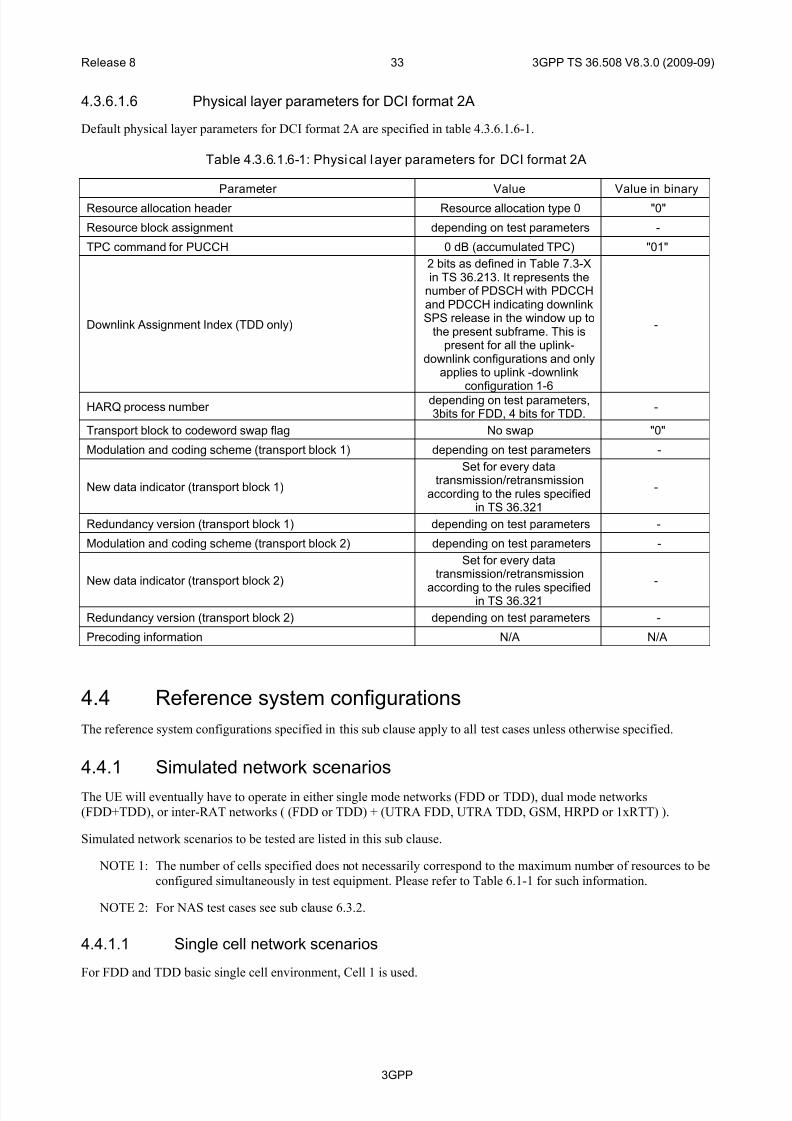
7/15/2019 Lte Sib Info
http://slidepdf.com/reader/full/lte-sib-info 33/187
3GPP
3GPP TS 36.508 V8.3.0 (2009-09)33Release 8
4.3.6.1.6 Physical layer parameters for DCI format 2A
Default physical layer parameters for DCI format 2A are specified in table 4.3.6.1.6-1.
Table 4.3.6.1.6-1: Physical layer parameters for DCI format 2A
Parameter Value Value in binaryResource allocation header Resource allocation type 0 "0"
Resource block assignment depending on test parameters -
TPC command for PUCCH 0 dB (accumulated TPC) "01"
Downlink Assignment Index (TDD only)
2 bits as defined in Table 7.3-Xin TS 36.213. It represents the
number of PDSCH with PDCCHand PDCCH indicating downlinkSPS release in the window up to
the present subframe. This ispresent for all the uplink-
downlink configurations and onlyapplies to uplink -downlink
configuration 1-6
-
HARQ process number depending on test parameters,3bits for FDD, 4 bits for TDD.
-
Transport block to codeword swap flag No swap "0"
Modulation and coding scheme (transport block 1) depending on test parameters -
New data indicator (transport block 1)
Set for every datatransmission/retransmission
according to the rules specifiedin TS 36.321
-
Redundancy version (transport block 1) depending on test parameters -
Modulation and coding scheme (transport block 2) depending on test parameters -
New data indicator (transport block 2)
Set for every datatransmission/retransmission
according to the rules specifiedin TS 36.321
-
Redundancy version (transport block 2) depending on test parameters -
Precoding information N/A N/A
4.4 Reference system configurations
The reference system configurations specified in this sub clause apply to all test cases unless otherwise specified.
4.4.1 Simulated network scenarios
The UE will eventually have to operate in either single mode networks (FDD or TDD), dual mode networks(FDD+TDD), or inter-RAT networks ( (FDD or TDD) + (UTRA FDD, UTRA TDD, GSM, HRPD or 1xRTT) ).
Simulated network scenarios to be tested are listed in this sub clause.
NOTE 1: The number of cells specified does not necessarily correspond to the maximum number of resources to beconfigured simultaneously in test equipment. Please refer to Table 6.1-1 for such information.
NOTE 2: For NAS test cases see sub clause 6.3.2.
4.4.1.1 Single cell network scenarios
For FDD and TDD basic single cell environment, Cell 1 is used.
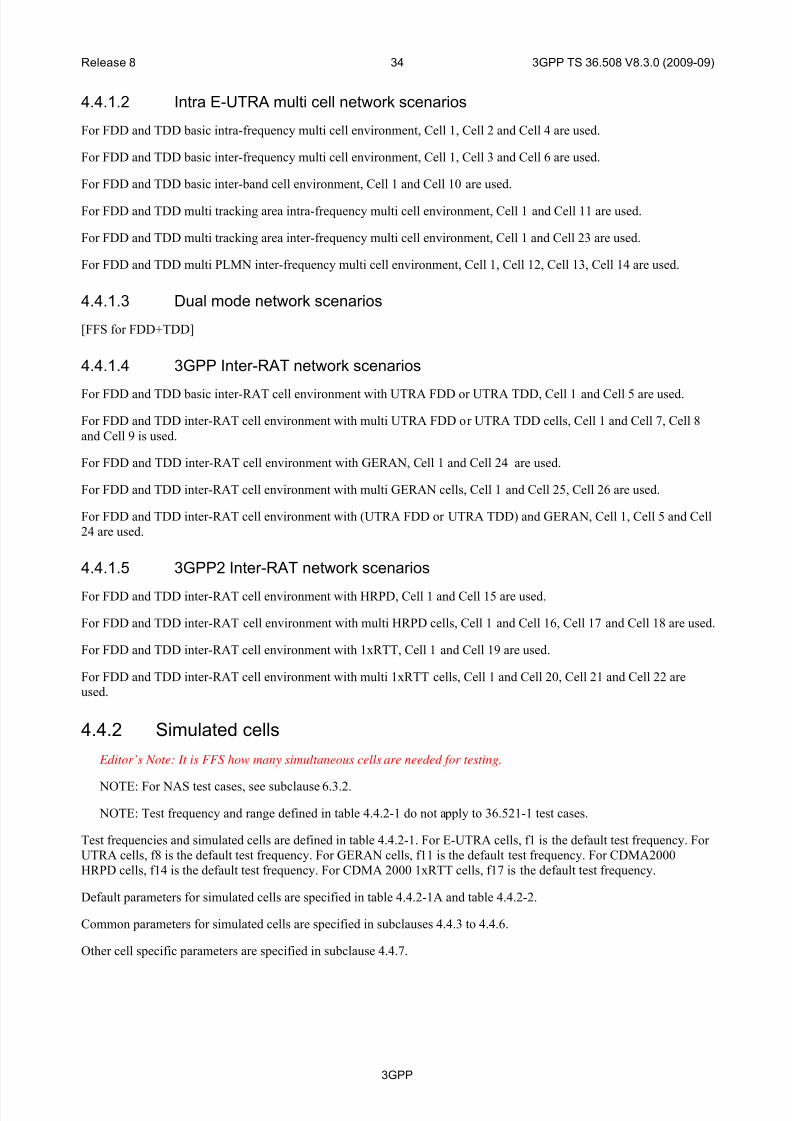
7/15/2019 Lte Sib Info
http://slidepdf.com/reader/full/lte-sib-info 34/187
3GPP
3GPP TS 36.508 V8.3.0 (2009-09)34Release 8
4.4.1.2 Intra E-UTRA multi cell network scenarios
For FDD and TDD basic intra-frequency multi cell environment, Cell 1, Cell 2 and Cell 4 are used.
For FDD and TDD basic inter-frequency multi cell environment, Cell 1, Cell 3 and Cell 6 are used.
For FDD and TDD basic inter-band cell environment, Cell 1 and Cell 10 are used.
For FDD and TDD multi tracking area intra-frequency multi cell environment, Cell 1 and Cell 11 are used.
For FDD and TDD multi tracking area inter-frequency multi cell environment, Cell 1 and Cell 23 are used.
For FDD and TDD multi PLMN inter-frequency multi cell environment, Cell 1, Cell 12, Cell 13, Cell 14 are used.
4.4.1.3 Dual mode network scenarios
[FFS for FDD+TDD]
4.4.1.4 3GPP Inter-RAT network scenarios
For FDD and TDD basic inter-RAT cell environment with UTRA FDD or UTRA TDD, Cell 1 and Cell 5 are used.
For FDD and TDD inter-RAT cell environment with multi UTRA FDD or UTRA TDD cells, Cell 1 and Cell 7, Cell 8and Cell 9 is used.
For FDD and TDD inter-RAT cell environment with GERAN, Cell 1 and Cell 24 are used.
For FDD and TDD inter-RAT cell environment with multi GERAN cells, Cell 1 and Cell 25, Cell 26 are used.
For FDD and TDD inter-RAT cell environment with (UTRA FDD or UTRA TDD) and GERAN, Cell 1, Cell 5 and Cell24 are used.
4.4.1.5 3GPP2 Inter-RAT network scenarios
For FDD and TDD inter-RAT cell environment with HRPD, Cell 1 and Cell 15 are used.
For FDD and TDD inter-RAT cell environment with multi HRPD cells, Cell 1 and Cell 16, Cell 17 and Cell 18 are used.
For FDD and TDD inter-RAT cell environment with 1xRTT, Cell 1 and Cell 19 are used.
For FDD and TDD inter-RAT cell environment with multi 1xRTT cells, Cell 1 and Cell 20, Cell 21 and Cell 22 areused.
4.4.2 Simulated cells
Editor’s Note: It is FFS how many simultaneous cells are needed for testing.
NOTE: For NAS test cases, see subclause 6.3.2.
NOTE: Test frequency and range defined in table 4.4.2-1 do not apply to 36.521-1 test cases.
Test frequencies and simulated cells are defined in table 4.4.2-1. For E-UTRA cells, f1 is the default test frequency. For UTRA cells, f8 is the default test frequency. For GERAN cells, f11 is the default test frequency. For CDMA2000HRPD cells, f14 is the default test frequency. For CDMA 2000 1xRTT cells, f17 is the default test frequency.
Default parameters for simulated cells are specified in table 4.4.2-1A and table 4.4.2-2.
Common parameters for simulated cells are specified in subclauses 4.4.3 to 4.4.6.
Other cell specific parameters are specified in subclause 4.4.7.

7/15/2019 Lte Sib Info
http://slidepdf.com/reader/full/lte-sib-info 35/187
3GPP
3GPP TS 36.508 V8.3.0 (2009-09)35Release 8
Table 4.4.2-1: Definition of test frequencies and simulated cells
Testfrequency
RAT Operating band Range Simulated cells
f1 E-UTRA Operating band under test Mid Cell 1, Cell 2, Cell 4, Cell 11
f2 E-UTRA Operating band under test High Cell 3, Cell 12, Cell 23
f3 E-UTRA Operating band under test Low Cell 6, Cell 13
f4 E-UTRA Operating band under test [FFS] Cell 14f5 E-UTRA Operating band for inter-band cells Mid Cell 10
f6 E-UTRA Operating band for inter-band cells High
f7 E-UTRA Operating band for inter-band cells Low
f8 UTRA Operating band for UTRA cells Mid Cell 5, Cell 7
f9 UTRA Operating band for UTRA cells High Cell 8
f10 UTRA Operating band for UTRA cells Low Cell 9
f11 GERAN Operating band for GERAN cells Mid Cell 24
f12 GERAN Operating band for GERAN cells High Cell 25
f13 GERAN Operating band for GERAN cells Low Cell 26
f14 CDMA2000HRPD
Operating band for CDMA2000 HRPDcells
FFS Cell 15, Cell 16
f15 CDMA2000HRPD
Operating band for CDMA2000 HRPDcells
FFS Cell 17
f16 CDMA2000HRPD
Operating band for CDMA2000 HRPDcells
FFS Cell 18
f17 CDMA20001xRTT
Operating band for CDMA2000 1xRTTcells
FFS Cell 19, Cell 20
f18 CDMA20001xRTT
Operating band for CDMA2000 1xRTTcells
FFS Cell 21
f19 CDMA20001xRTT
Operating band for CDMA2000 1xRTTcells
FFS Cell 22
Table 4.4.2-1A: Default E-UTRA parameters fo r s imulated cells
E-UTRAN Cell Identifier cell ID
eNB Identifi er Cell Identity
Physical layer cell
identityCell 1 '0000 0000 0000 0000 0001'B '0000 0000'B 0
Cell 2 '0000 0000 0000 0000 0001'B '0000 0010'B 2
Cell 3 '0000 0000 0000 0000 0010'B '0000 0011'B 3
Cell 4 '0000 0000 0000 0000 0011'B '0000 0100'B 4
Cell 6 '0000 0000 0000 0000 0100'B '0000 0110'B 6
Cell 10 '0000 0000 0000 0000 0101'B '0000 1010'B 10
Cell 11 '0000 0000 0000 0000 0110'B '0000 1011'B 11
Cell 12 '0000 0000 0000 0000 0010'B '0000 1100'B 12
Cell 13 '0000 0000 0000 0000 0100'B '0000 1101'B 13
Cell 14 '0000 0000 0000 0000 0111'B '0000 1110'B 14
Cell 23 '0000 0000 0000 0000 0110'B '0001 0111'B 23
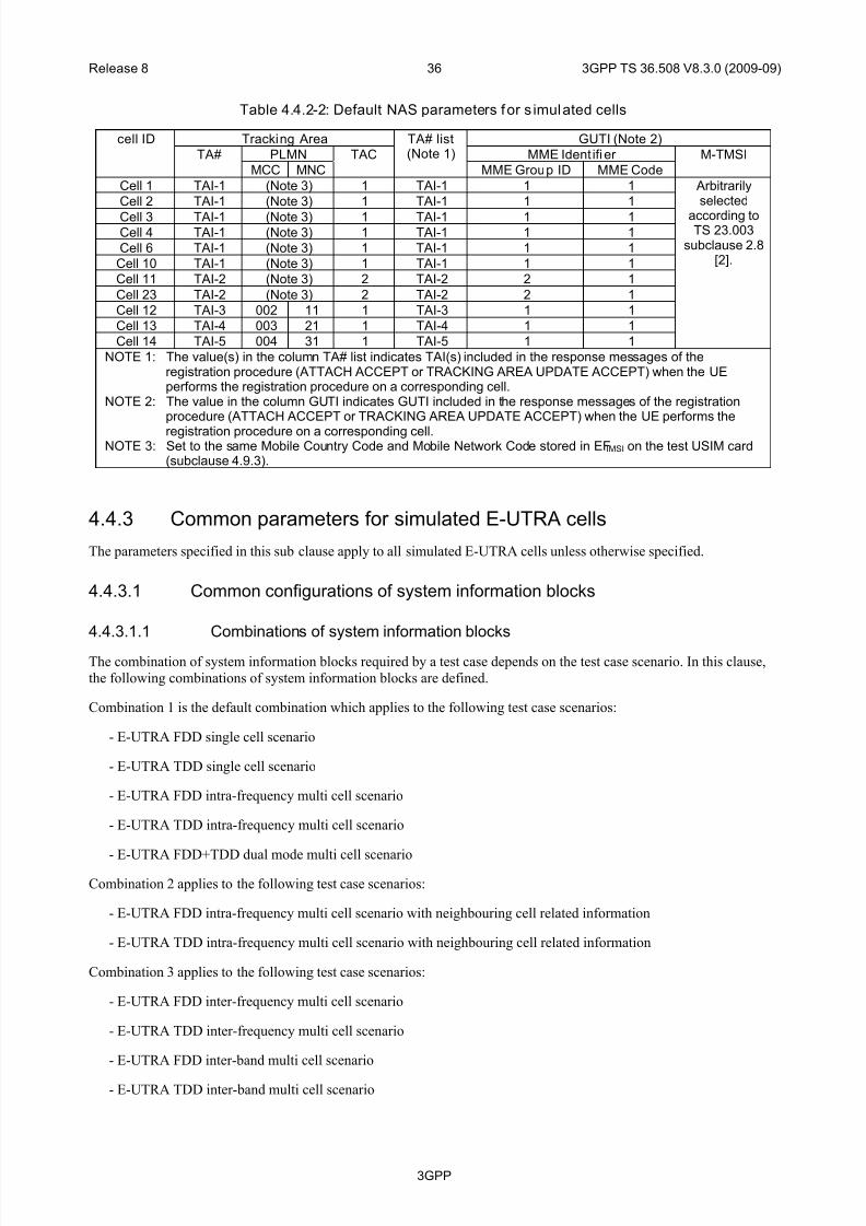
7/15/2019 Lte Sib Info
http://slidepdf.com/reader/full/lte-sib-info 36/187
3GPP
3GPP TS 36.508 V8.3.0 (2009-09)36Release 8
Table 4.4.2-2: Default NAS parameters for s imulated cells
Tracking Area GUTI (Note 2)
PLMN MME Ident ifi er
cell ID
TA#
MCC MNC
TAC
TA# list(Note 1)
MME Group ID MME Code
M-TMSI
Cell 1 TAI-1 (Note 3) 1 TAI-1 1 1
Cell 2 TAI-1 (Note 3) 1 TAI-1 1 1
Cell 3 TAI-1 (Note 3) 1 TAI-1 1 1Cell 4 TAI-1 (Note 3) 1 TAI-1 1 1
Cell 6 TAI-1 (Note 3) 1 TAI-1 1 1
Cell 10 TAI-1 (Note 3) 1 TAI-1 1 1
Cell 11 TAI-2 (Note 3) 2 TAI-2 2 1
Cell 23 TAI-2 (Note 3) 2 TAI-2 2 1
Cell 12 TAI-3 002 11 1 TAI-3 1 1
Cell 13 TAI-4 003 21 1 TAI-4 1 1
Cell 14 TAI-5 004 31 1 TAI-5 1 1
Arbitrarilyselected
according toTS 23.003
subclause 2.8[2].
NOTE 1: The value(s) in the column TA# list indicates TAI(s) included in the response messages of theregistration procedure (ATTACH ACCEPT or TRACKING AREA UPDATE ACCEPT) when the UEperforms the registration procedure on a corresponding cell.
NOTE 2: The value in the column GUTI indicates GUTI included in the response messages of the registrationprocedure (ATTACH ACCEPT or TRACKING AREA UPDATE ACCEPT) when the UE performs theregistration procedure on a corresponding cell.
NOTE 3: Set to the same Mobile Country Code and Mobile Network Code stored in EFIMSI on the test USIM card(subclause 4.9.3).
4.4.3 Common parameters for simulated E-UTRA cells
The parameters specified in this sub clause apply to all simulated E-UTRA cells unless otherwise specified.
4.4.3.1 Common configurations of system information blocks
4.4.3.1.1 Combinations of system information blocksThe combination of system information blocks required by a test case depends on the test case scenario. In this clause,the following combinations of system information blocks are defined.
Combination 1 is the default combination which applies to the following test case scenarios:
- E-UTRA FDD single cell scenario
- E-UTRA TDD single cell scenario
- E-UTRA FDD intra-frequency multi cell scenario
- E-UTRA TDD intra-frequency multi cell scenario
- E-UTRA FDD+TDD dual mode multi cell scenario
Combination 2 applies to the following test case scenarios:
- E-UTRA FDD intra-frequency multi cell scenario with neighbouring cell related information
- E-UTRA TDD intra-frequency multi cell scenario with neighbouring cell related information
Combination 3 applies to the following test case scenarios:
- E-UTRA FDD inter-frequency multi cell scenario
- E-UTRA TDD inter-frequency multi cell scenario
- E-UTRA FDD inter-band multi cell scenario- E-UTRA TDD inter-band multi cell scenario
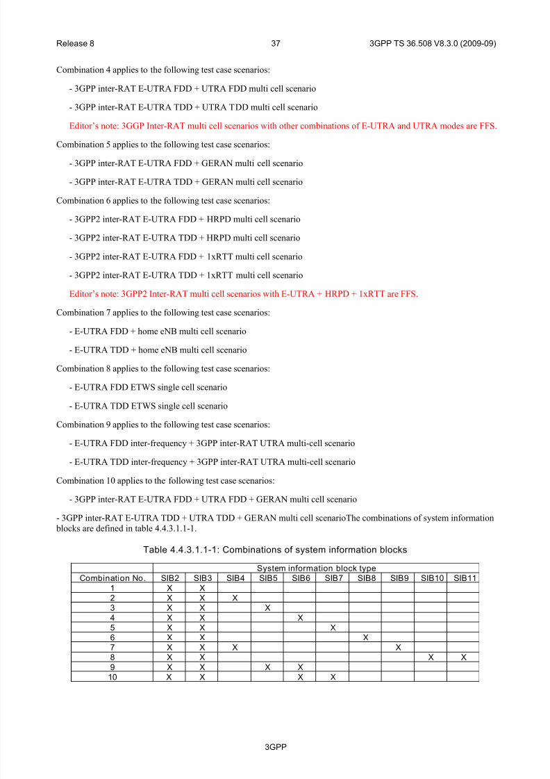
7/15/2019 Lte Sib Info
http://slidepdf.com/reader/full/lte-sib-info 37/187
3GPP
3GPP TS 36.508 V8.3.0 (2009-09)37Release 8
Combination 4 applies to the following test case scenarios:
- 3GPP inter-RAT E-UTRA FDD + UTRA FDD multi cell scenario
- 3GPP inter-RAT E-UTRA TDD + UTRA TDD multi cell scenario
Editor’s note: 3GGP Inter-RAT multi cell scenarios with other combinations of E-UTRA and UTRA modes are FFS.
Combination 5 applies to the following test case scenarios:
- 3GPP inter-RAT E-UTRA FDD + GERAN multi cell scenario
- 3GPP inter-RAT E-UTRA TDD + GERAN multi cell scenario
Combination 6 applies to the following test case scenarios:
- 3GPP2 inter-RAT E-UTRA FDD + HRPD multi cell scenario
- 3GPP2 inter-RAT E-UTRA TDD + HRPD multi cell scenario
- 3GPP2 inter-RAT E-UTRA FDD + 1xRTT multi cell scenario
- 3GPP2 inter-RAT E-UTRA TDD + 1xRTT multi cell scenario
Editor’s note: 3GPP2 Inter-RAT multi cell scenarios with E-UTRA + HRPD + 1xRTT are FFS.
Combination 7 applies to the following test case scenarios:
- E-UTRA FDD + home eNB multi cell scenario
- E-UTRA TDD + home eNB multi cell scenario
Combination 8 applies to the following test case scenarios:
- E-UTRA FDD ETWS single cell scenario
- E-UTRA TDD ETWS single cell scenario
Combination 9 applies to the following test case scenarios:
- E-UTRA FDD inter-frequency + 3GPP inter-RAT UTRA multi-cell scenario
- E-UTRA TDD inter-frequency + 3GPP inter-RAT UTRA multi-cell scenario
Combination 10 applies to the following test case scenarios:
- 3GPP inter-RAT E-UTRA FDD + UTRA FDD + GERAN multi cell scenario
- 3GPP inter-RAT E-UTRA TDD + UTRA TDD + GERAN multi cell scenarioThe combinations of system information blocks are defined in table 4.4.3.1.1-1.
Table 4.4.3.1.1-1: Combinations of system information blocks
System information block type
Combination No. SIB2 SIB3 SIB4 SIB5 SIB6 SIB7 SIB8 SIB9 SIB10 SIB11
1 X X
2 X X X
3 X X X
4 X X X
5 X X X
6 X X X
7 X X X X
8 X X X X
9 X X X X
10 X X X X
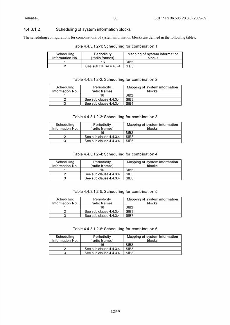
7/15/2019 Lte Sib Info
http://slidepdf.com/reader/full/lte-sib-info 38/187
3GPP
3GPP TS 36.508 V8.3.0 (2009-09)38Release 8
4.4.3.1.2 Scheduling of system information blocks
The scheduling configurations for combinations of system information blocks are defined in the following tables.
Table 4.4.3.1.2-1: Scheduling for combination 1
SchedulingInformation No.
Periodicity[radio frames]
Mapping of system informationblocks
1 16 SIB2
2 See sub clause 4.4.3.4 SIB3
Table 4.4.3.1.2-2: Scheduling for combination 2
SchedulingInformation No.
Periodicity[radio frames]
Mapping of system informationblocks
1 16 SIB2
2 See sub clause 4.4.3.4 SIB33 See sub clause 4.4.3.4 SIB4
Table 4.4.3.1.2-3: Scheduling for combination 3
SchedulingInformation No.
Periodicity[radio frames]
Mapping of system informationblocks
1 16 SIB2
2 See sub clause 4.4.3.4 SIB3
3 See sub clause 4.4.3.4 SIB5
Table 4.4.3.1.2-4: Scheduling for combination 4
SchedulingInformation No.
Periodicity[radio frames]
Mapping of system informationblocks
1 16 SIB22 See sub clause 4.4.3.4 SIB3
3 See sub clause 4.4.3.4 SIB6
Table 4.4.3.1.2-5: Scheduling for combination 5
SchedulingInformation No.
Periodicity[radio frames]
Mapping of system informationblocks
1 16 SIB2
2 See sub clause 4.4.3.4 SIB3
3 See sub clause 4.4.3.4 SIB7
Table 4.4.3.1.2-6: Scheduling for combination 6
SchedulingInformation No.
Periodicity[radio frames]
Mapping of system informationblocks
1 16 SIB2
2 See sub clause 4.4.3.4 SIB3
3 See sub clause 4.4.3.4 SIB8

7/15/2019 Lte Sib Info
http://slidepdf.com/reader/full/lte-sib-info 39/187
3GPP
3GPP TS 36.508 V8.3.0 (2009-09)39Release 8
Table 4.4.3.1.2-7: Scheduling for combination 7
SchedulingInformation No.
Periodicity[radio frames]
Mapping of system informationblocks
1 16 SIB2
2 See sub clause 4.4.3.4 SIB3
3 See subclause 4.4.3.4 SIB4
4 FFS SIB9
Table 4.4.3.1.2-8: Scheduling for combination 8
SchedulingInformation No.
Periodicity[radio frames]
Mapping of system informationblocks
1 16 SIB2
2 See sub clause 4.4.3.4 SIB3
3 FFS SIB11
4 FFS SIB10
Table 4.4.3.1.2-9: Scheduling for combination 9
SchedulingInformation No.
Periodicity[radio frames]
Mapping of system informationblocks
1 16 SIB2
2 See sub clause 4.4.3.4 SIB3
3 See sub clause 4.4.3.4 SIB5, SIB6
Table 4.4.3.1.2-10: Scheduling for combination 10
SchedulingInformation No.
Periodicity[radio frames]
Mapping of system informationblocks
1 16 SIB2
2 See sub clause 4.4.3.4 SIB33 See sub clause 4.4.3.4 SIB6
4 See sub clause 4.4.3.4 SIB7
4.4.3.2 Common contents of system information messages
- MasterInformationBlock
The MasterInformationBlock includes the system information transmitted on BCH.
Table 4.4.3.2-1: MasterInformationBlock
Derivation Path: 36.331 clause 6.2.2
Information Element Value/remark Comment Condit ion
MasterInformationBlock ::= SEQUENCE {
dl-Bandwidth Downlink systembandwidth under test.
phich-Config SEQUENCE {} PHICH-Config-DEFAULT See subclause4.6.3
systemFrameNumber A valid value as definedin TS 36.331 [17]
spare '0000 0000 00'B
}
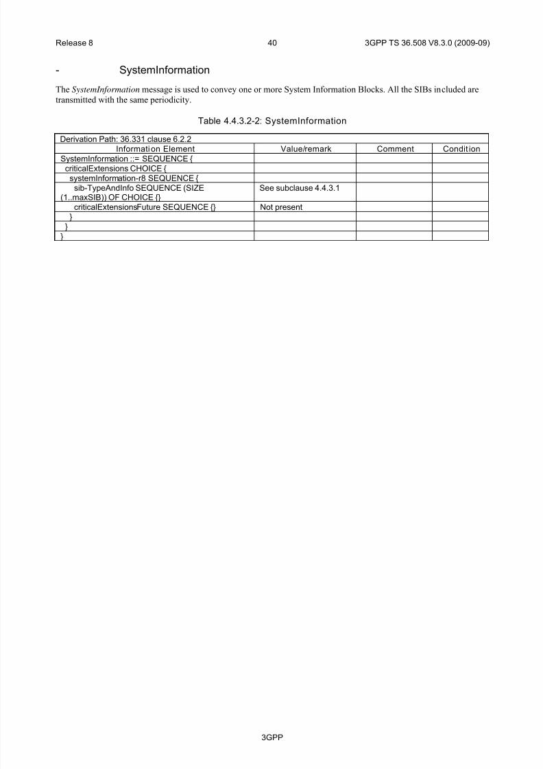
7/15/2019 Lte Sib Info
http://slidepdf.com/reader/full/lte-sib-info 40/187
3GPP
3GPP TS 36.508 V8.3.0 (2009-09)40Release 8
- SystemInformation
The SystemInformation message is used to convey one or more System Information Blocks. All the SIBs included aretransmitted with the same periodicity.
Table 4.4.3.2-2: SystemInformation
Derivation Path: 36.331 clause 6.2.2
Information Element Value/remark Comment Condit ion
SystemInformation ::= SEQUENCE {
criticalExtensions CHOICE {
systemInformation-r8 SEQUENCE {
sib-TypeAndInfo SEQUENCE (SIZE(1..maxSIB)) OF CHOICE {}
See subclause 4.4.3.1
criticalExtensionsFuture SEQUENCE {} Not present
}
}
}
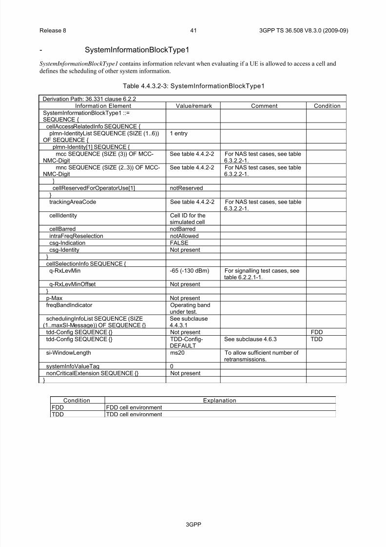
7/15/2019 Lte Sib Info
http://slidepdf.com/reader/full/lte-sib-info 41/187
3GPP
3GPP TS 36.508 V8.3.0 (2009-09)41Release 8
- SystemInformationBlockType1
SystemInformationBlockType1 contains information relevant when evaluating if a UE is allowed to access a cell anddefines the scheduling of other system information.
Table 4.4.3.2-3: SystemInformationBlockType1
Derivation Path: 36.331 clause 6.2.2
Information Element Value/remark Comment Condit ion
SystemInformationBlockType1 ::=SEQUENCE {
cellAccessRelatedInfo SEQUENCE {
plmn-IdentityList SEQUENCE (SIZE (1..6))OF SEQUENCE {
1 entry
plmn-Identity[1] SEQUENCE {
mcc SEQUENCE (SIZE (3)) OF MCC-NMC-Digit
See table 4.4.2-2 For NAS test cases, see table6.3.2.2-1.
mnc SEQUENCE (SIZE (2..3)) OF MCC-NMC-Digit
See table 4.4.2-2 For NAS test cases, see table6.3.2.2-1.
}
cellReservedForOperatorUse[1] notReserved}
trackingAreaCode See table 4.4.2-2 For NAS test cases, see table6.3.2.2-1.
cellIdentity Cell ID for thesimulated cell
cellBarred notBarred
intraFreqReselection notAllowed
csg-Indication FALSE
csg-Identity Not present
}
cellSelectionInfo SEQUENCE {
q-RxLevMin -65 (-130 dBm) For signalling test cases, seetable 6.2.2.1-1.
q-RxLevMinOffset Not present}
p-Max Not present
freqBandIndicator Operating bandunder test.
schedulingInfoList SEQUENCE (SIZE(1..maxSI-Message)) OF SEQUENCE {}
See subclause4.4.3.1
tdd-Config SEQUENCE {} Not present FDD
tdd-Config SEQUENCE {} TDD-Config-DEFAULT
See subclause 4.6.3 TDD
si-WindowLength ms20 To allow sufficient number of retransmissions.
systemInfoValueTag 0
nonCriticalExtension SEQUENCE {} Not present
}
Condition Explanation
FDD FDD cell environment
TDD TDD cell environment
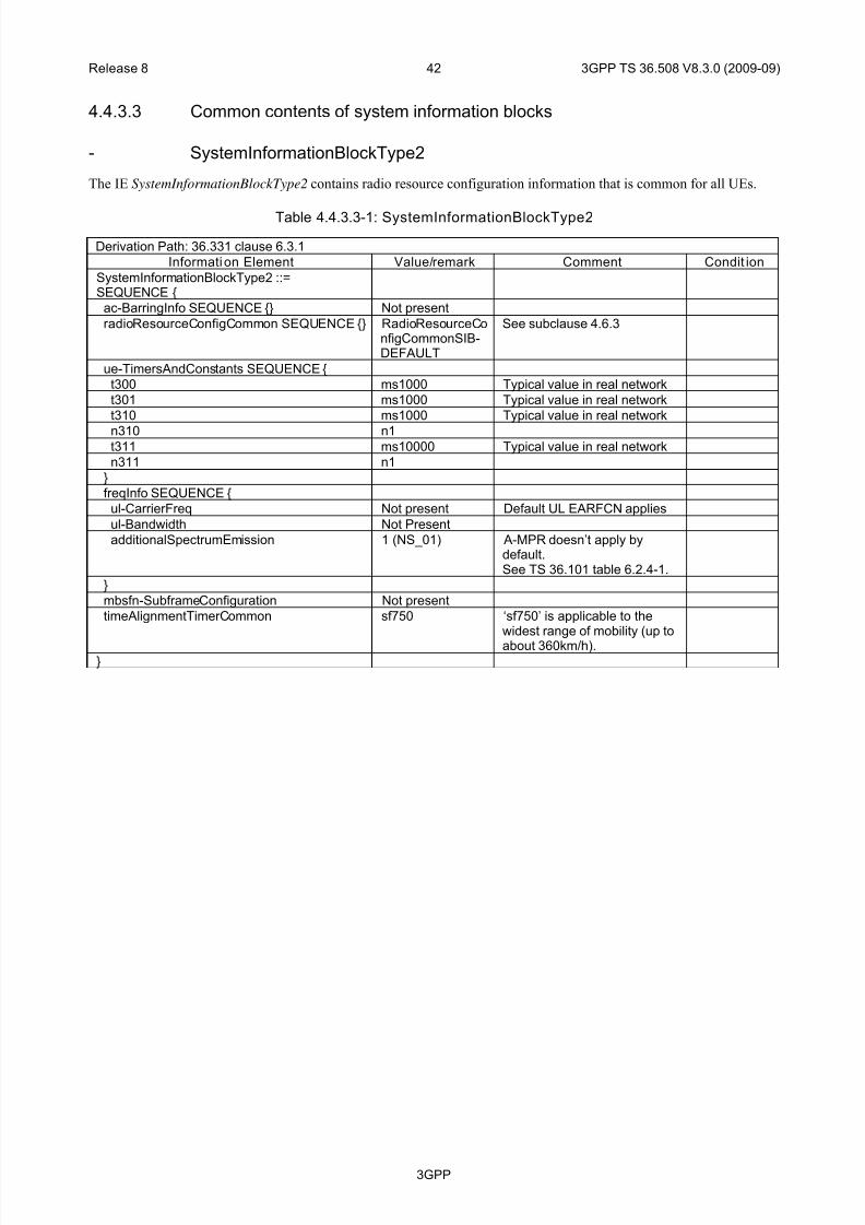
7/15/2019 Lte Sib Info
http://slidepdf.com/reader/full/lte-sib-info 42/187
3GPP
3GPP TS 36.508 V8.3.0 (2009-09)42Release 8
4.4.3.3 Common contents of system information blocks
- SystemInformationBlockType2
The IE SystemInformationBlockType2 contains radio resource configuration information that is common for all UEs.
Table 4.4.3.3-1: SystemInformationBlockType2
Derivation Path: 36.331 clause 6.3.1
Information Element Value/remark Comment Condit ion
SystemInformationBlockType2 ::=SEQUENCE {
ac-BarringInfo SEQUENCE {} Not present
radioResourceConfigCommon SEQUENCE {} RadioResourceConfigCommonSIB-DEFAULT
See subclause 4.6.3
ue-TimersAndConstants SEQUENCE {
t300 ms1000 Typical value in real network
t301 ms1000 Typical value in real network
t310 ms1000 Typical value in real network
n310 n1
t311 ms10000 Typical value in real network
n311 n1
}
freqInfo SEQUENCE {
ul-CarrierFreq Not present Default UL EARFCN applies
ul-Bandwidth Not Present
additionalSpectrumEmission 1 (NS_01) A-MPR doesn’t apply bydefault.See TS 36.101 table 6.2.4-1.
}
mbsfn-SubframeConfiguration Not present
timeAlignmentTimerCommon sf750 ‘sf750’ is applicable to thewidest range of mobility (up toabout 360km/h).
}

7/15/2019 Lte Sib Info
http://slidepdf.com/reader/full/lte-sib-info 43/187
3GPP
3GPP TS 36.508 V8.3.0 (2009-09)43Release 8
- SystemInformationBlockType3
The IE SystemInformationBlockType3 contains cell re-selection information common for intra-frequency, inter-frequency and/or inter-RAT cell re-selection (i.e. applicable for more than one type of cell re-selection but notnecessarily all) as well as intra-frequency cell re-selection information other than neighbouring cell related.
Table 4.4.3.3-2: SystemInformationBlockType3
Derivation Path: 36.331 clause 6.3.1
Information Element Value/remark Comment Condit ion
SystemInformationBlockType3 ::= SEQUENCE {
cellReselectionInfoCommon SEQUENCE {
q-Hyst dB0 To reduceinterferencebetween intra-frequency multiplecells
speedStateReselectionPars SEQUENCE {} Not present
}
cellReselectionServingFreqInfo SEQUENCE {
s-NonIntraSearch Not presentthreshServingLow 0 (0 dB) Typical value in
real network
cellReselectionPriority 4 A middle value inthe range hasbeen selected.
}
intraFreqCellReselectionInfo SEQUENCE {
q-RxLevMin -70 (-140 dBm) For signalling testcases, see table6.2.2.1-1.
p-Max Not present
s-IntraSearch Not present
allowedMeasBandwidth Not present The downlink
bandwidth of theserving cellapplies.
presenceAntennaPort1 FALSE
neighCellConfig '01'B (No MBSFNsubframes are present inall neighbour cells)
MBSFN doesn’tapply by default.
t-ReselectionEUTRA 0 Typical value inreal network
t-ReselectionEUTRA-SF Not present
}
}
- SystemInformationBlockType4
The IE SystemInformationBlockType4 contains neighbouring cell related information relevant only for intra-frequencycell re-selection. The IE includes cells with specific re-selection parameters as well as blacklisted cells.
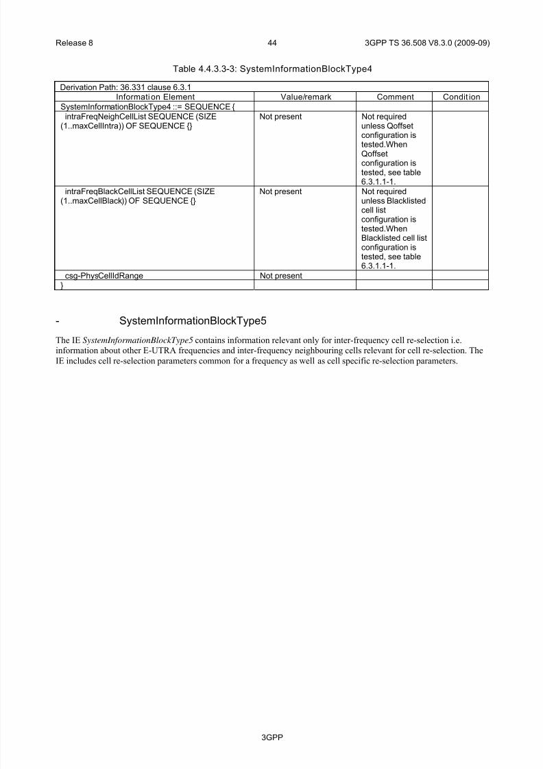
7/15/2019 Lte Sib Info
http://slidepdf.com/reader/full/lte-sib-info 44/187
3GPP
3GPP TS 36.508 V8.3.0 (2009-09)44Release 8
Table 4.4.3.3-3: SystemInformationBlockType4
Derivation Path: 36.331 clause 6.3.1Information Element Value/remark Comment Condit ion
SystemInformationBlockType4 ::= SEQUENCE {
intraFreqNeighCellList SEQUENCE (SIZE(1..maxCellIntra)) OF SEQUENCE {}
Not present Not requiredunless Qoffset
configuration istested.WhenQoffsetconfiguration istested, see table6.3.1.1-1.
intraFreqBlackCellList SEQUENCE (SIZE(1..maxCellBlack)) OF SEQUENCE {}
Not present Not requiredunless Blacklistedcell listconfiguration istested.WhenBlacklisted cell listconfiguration istested, see table
6.3.1.1-1.csg-PhysCellIdRange Not present
}
- SystemInformationBlockType5
The IE SystemInformationBlockType5 contains information relevant only for inter-frequency cell re-selection i.e.information about other E-UTRA frequencies and inter-frequency neighbouring cells relevant for cell re-selection. TheIE includes cell re-selection parameters common for a frequency as well as cell specific re-selection parameters.

7/15/2019 Lte Sib Info
http://slidepdf.com/reader/full/lte-sib-info 45/187
3GPP
3GPP TS 36.508 V8.3.0 (2009-09)45Release 8
Table 4.4.3.3-4: SystemInformationBlockType5
Derivation Path: 36.331 clause 6.3.1Information Element Value/remark Comment Condit ion
SystemInformationBlockType5 ::= SEQUENCE {
interFreqCarrierFreqList SEQUENCE (SIZE(1..maxFreq)) OF SEQUENCE {
The same number of entries as the configured
inter-freq carriersFor Signalling test casesexcept NAS, see table6.3.1.2-1.For NAS test cases whencells are on same PLMN,see table 6.3.2.3.2-1.
n denotes theindex of the entry
dl-CarrierFreq[n] Downlink EARFCN under testFor Signalling test casesexcept NAS, see table6.3.1.2-1.For NAS test cases whencells are on same PLMN,
see table 6.3.2.3.2-1.q-RxLevMin[n] -65 (-130 dBm) For signalling test
cases, see table6.2.2.1-1.
p-Max[n] Not present
t-ReselectionEUTRA[n] 0 Typical value inreal network
t-ReselectionEUTRA-SF[n] Not present Not requiredunless speed-dependent cell re-selection is tested.
threshX-High[n] 2 (4 dB) This value shouldbe higher thanthreshServingLow
of the serving cellto avoid ping-pongwith lower prioritycells.
threshX-Low[n] 1 (2 dB)
allowedMeasBandwidth[n] See subclause 4.4.3.4 Channel-bandwidth-dependentparameter
presenceAntennaPort1[n] FALSE
cellReselectionPriority[n] 4 The same priorityas the one usedfor serving cell inSIB 3.
neighCellConfig[n] '01'B (No MBSFNsubframes are present inall neighbour cells)
MBSFN doesn’tapply by default.
q-OffsetFreq[n] dB0 Qoffset doesn’tapply by default.
interFreqNeighCellList[n] SEQUENCE (SIZE(1..maxCellInter)) OF SEQUENCE {}
Not present Not requiredunless Qoffsetconfiguration istested.
interFreqBlackCellList[n] SEQUENCE (SIZE(1..maxCellBlack)) OF SEQUENCE {}
Not present Not requiredunless Blacklistedcell listconfiguration istested.
}
}

7/15/2019 Lte Sib Info
http://slidepdf.com/reader/full/lte-sib-info 46/187
3GPP
3GPP TS 36.508 V8.3.0 (2009-09)46Release 8
- SystemInformationBlockType6
The IE SystemInformationBlockType6 contains information relevant only for inter-RAT cell re-selection i.e.information about UTRA frequencies and UTRA neighbouring cells relevant for cell re-selection. The IE includes cellre-selection parameters common for a frequency.
Table 4.4.3.3-5: SystemInformationBlockType6
Derivation Path: 36.331 clause 6.3.1
Information Element Value/remark Comment Condit ion
SystemInformationBlockType6 ::= SEQUENCE {
carrierFreqListUTRA-FDD SEQUENCE (SIZE(1..maxUTRA-FDD-Carrier)) OF SEQUENCE {}
Not present UTRA-TDD
carrierFreqListUTRA-FDD SEQUENCE (SIZE(1..maxUTRA-FDD-Carrier)) OF SEQUENCE {
The same number of entries as the configuredUTRA FDD carriersFor Signalling test cases,see table 6.3.1.3-1
n denotes theindex of the entry
UTRA-FDD
carrierFreq[n] Downlink UARFCN under test
For Signalling test cases,see table 6.3.1.3-1
cellReselectionPriority[n] 3
threshX-High[n] 2 (4 dB)
threshX-Low[n] 1 (2 dB)
q-RxLevMin[n] -40 (-79 dBm) The same valueas defined in TS34.108 [5], table6.1.1.
p-MaxUTRA[n] 21 (21 dBm) The same valueas defined in TS34.108 [5], table6.1.1.
q-QualMin[n] -24 (-24 dB) The same value
as defined in TS34.108 [5], table6.1.1.
}
carrierFreqListUTRA-TDD SEQUENCE (SIZE(1..maxUTRA-TDD-Carrier)) OF SEQUENCE {}
Not present UTRA-FDD
carrierFreqListUTRA-TDD SEQUENCE (SIZE(1..maxUTRA-TDD-Carrier)) OF SEQUENCE {
The same number of entries as the configuredUTRA TDD carriersFor Signalling test cases,see table 6.3.1.3-1
n denotes theindex of the entry
UTRA-TDD
carrierFreq[n] Downlink UARFCN under testFor Signalling test cases,see table 6.3.1.3-1
cellReselectionPriority[n] 3
threshX-High[n] 2 (4 dB)
threshX-Low[n] 1 (2 dB)
q-RxLevMin[n] -41 (-81 dBm) The same valueas defined in TS34.108 [5], table6.1.6a
p-MaxUTRA[n] 21 (21 dBm) The same valueas defined in TS34.108 [5], table6.1.6a
}
t-ReselectionUTRA 0 Typical value inreal network
t-ReselectionUTRA-SF Not present
}
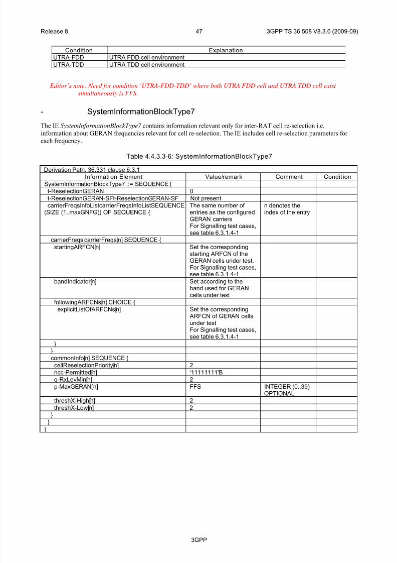
7/15/2019 Lte Sib Info
http://slidepdf.com/reader/full/lte-sib-info 47/187
3GPP
3GPP TS 36.508 V8.3.0 (2009-09)47Release 8
Condition Explanation
UTRA-FDD UTRA FDD cell environment
UTRA-TDD UTRA TDD cell environment
Editor’s note: Need for condition ‘UTRA-FDD-TDD’ where both UTRA FDD cell and UTRA TDD cell exist
simultaneously is FFS.
- SystemInformationBlockType7
The IE SystemInformationBlockType7 contains information relevant only for inter-RAT cell re-selection i.e.information about GERAN frequencies relevant for cell re-selection. The IE includes cell re-selection parameters for each frequency.
Table 4.4.3.3-6: SystemInformationBlockType7
Derivation Path: 36.331 clause 6.3.1Information Element Value/remark Comment Condit ion
SystemInformationBlockType7 ::= SEQUENCE {
t-ReselectionGERAN 0
t-ReselectionGERAN-SFt-ReselectionGERAN-SF Not present
carrierFreqsInfoListcarrierFreqsInfoListSEQUENCE(SIZE (1..maxGNFG)) OF SEQUENCE {
The same number of entries as the configuredGERAN carriersFor Signalling test cases,see table 6.3.1.4-1
n denotes theindex of the entry
carrierFreqs carrierFreqs[n] SEQUENCE {
startingARFCN[n] Set the correspondingstarting ARFCN of theGERAN cells under test.For Signalling test cases,see table 6.3.1.4-1
bandIndicator[n] Set according to theband used for GERAN
cells under testfollowingARFCNs[n] CHOICE {
explicitListOfARFCNs[n] Set the corresponding ARFCN of GERAN cellsunder testFor Signalling test cases,see table 6.3.1.4-1
}
}
commonInfo[n] SEQUENCE {
cellReselectionPriority[n] 2
ncc-Permitted[n] ‘11111111'B
q-RxLevMin[n] 2
p-MaxGERAN[n] FFS INTEGER (0..39)
OPTIONALthreshX-High[n] 2
threshX-Low[n] 2
}
}
}
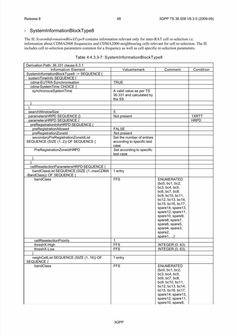
7/15/2019 Lte Sib Info
http://slidepdf.com/reader/full/lte-sib-info 48/187
3GPP
3GPP TS 36.508 V8.3.0 (2009-09)48Release 8
- SystemInformationBlockType8
The IE SystemInformationBlockType8 contains information relevant only for inter-RAT cell re-selection i.e.information about CDMA2000 frequencies and CDMA2000 neighbouring cells relevant for cell re-selection. The IEincludes cell re-selection parameters common for a frequency as well as cell specific re-selection parameters.
Table 4.4.3.3-7: SystemInformationBlockType8
Derivation Path: 36.331 clause 6.3.1
Information Element Value/remark Comment Condit ion
SystemInformationBlockType8 ::= SEQUENCE {
systemTimeInfo SEQUENCE {
cdma-EUTRA-Synchronisation TRUE
cdma-SystemTime CHOICE {
synchronousSystemTime A valid value as per TS36.331 and calculated bythe SS
}
}
searchWindowSize 5
parametersHRPD SEQUENCE {} Not present 1XRTTparametersHRPD SEQUENCE { HRPD
preRegistrationInfoHRPD SEQUENCE {
preRegistrationAllowed FALSE
preRegistrationZoneId Not present
secondaryPreRegistrationZoneIdListSEQUENCE (SIZE (1..2)) OF SEQUENCE {
Set the number of entriesaccording to specific testcase
PreRegistrationZoneIdHRPD Set according to specifictest case
}
}
cellReselectionParametersHRPD SEQUENCE {
bandClassList SEQUENCE (SIZE (1..maxCDMA
-BandClass)) OF SEQUENCE {
1 entry
bandClass FFS ENUMERATED{bc0, bc1, bc2,bc3, bc4, bc5,bc6, bc7, bc8,bc9, bc10, bc11,bc12, bc13, bc14,bc15, bc16, bc17,spare14, spare13,spare12, spare11,spare10, spare9,spare8, spare7,spare6, spare5,spare4, spare3,
spare2,spare1, ...}
cellReselectionPriority 1
threshX-High FFS INTEGER (0..63)
threshX-Low FFS INTEGER (0..63)
}
neighCellList SEQUENCE (SIZE (1..16)) OFSEQUENCE {
1 entry
bandClass FFS ENUMERATED{bc0, bc1, bc2,bc3, bc4, bc5,bc6, bc7, bc8,bc9, bc10, bc11,bc12, bc13, bc14,
bc15, bc16, bc17,spare14, spare13,spare12, spare11,spare10, spare9,
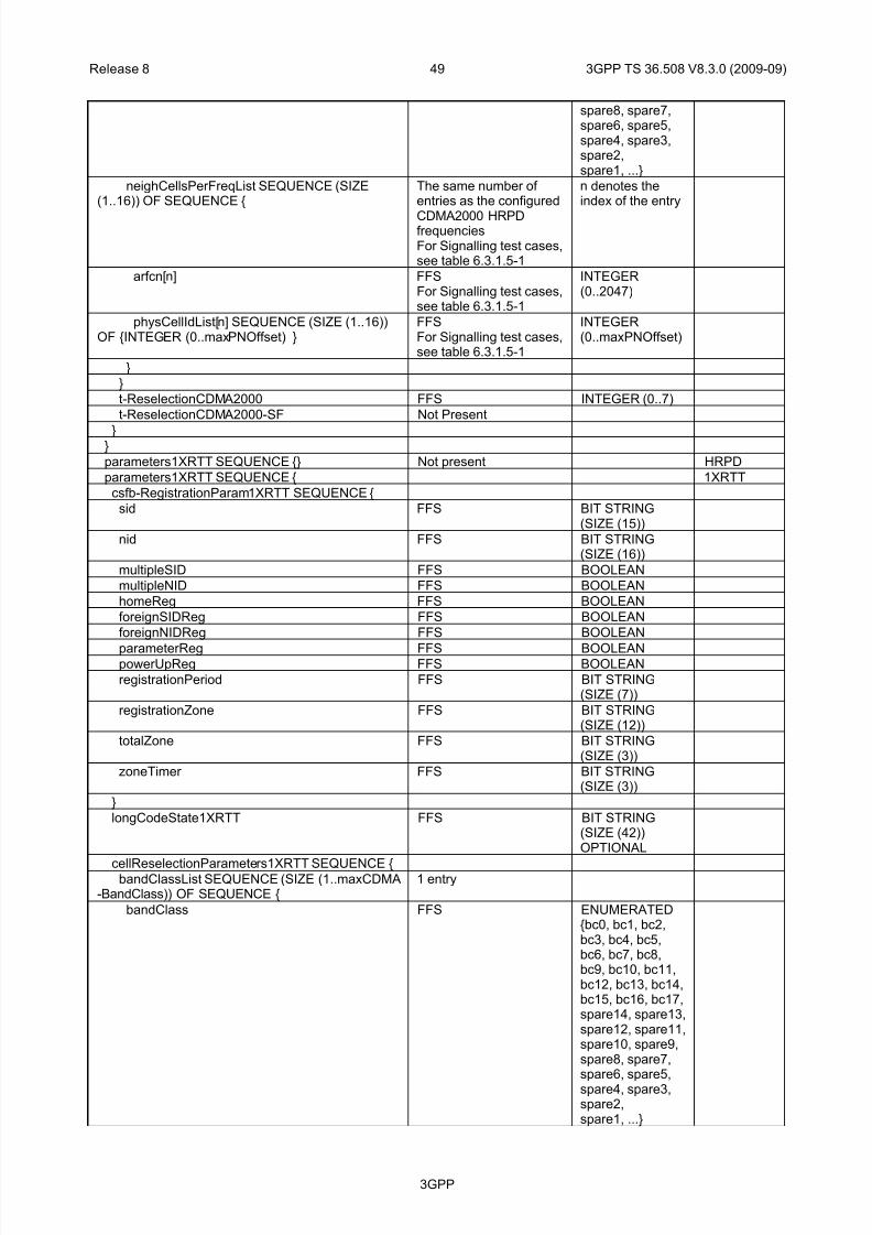
7/15/2019 Lte Sib Info
http://slidepdf.com/reader/full/lte-sib-info 49/187
3GPP
3GPP TS 36.508 V8.3.0 (2009-09)49Release 8
spare8, spare7,spare6, spare5,spare4, spare3,spare2,spare1, ...}
neighCellsPerFreqList SEQUENCE (SIZE(1..16)) OF SEQUENCE {
The same number of entries as the configured
CDMA2000 HRPDfrequenciesFor Signalling test cases,see table 6.3.1.5-1
n denotes theindex of the entry
arfcn[n] FFSFor Signalling test cases,see table 6.3.1.5-1
INTEGER(0..2047)
physCellIdList[n] SEQUENCE (SIZE (1..16))OF {INTEGER (0..maxPNOffset) }
FFSFor Signalling test cases,see table 6.3.1.5-1
INTEGER(0..maxPNOffset)
}
}
t-ReselectionCDMA2000 FFS INTEGER (0..7)
t-ReselectionCDMA2000-SF Not Present
}}
parameters1XRTT SEQUENCE {} Not present HRPD
parameters1XRTT SEQUENCE { 1XRTT
csfb-RegistrationParam1XRTT SEQUENCE {
sid FFS BIT STRING(SIZE (15))
nid FFS BIT STRING(SIZE (16))
multipleSID FFS BOOLEAN
multipleNID FFS BOOLEAN
homeReg FFS BOOLEAN
foreignSIDReg FFS BOOLEAN
foreignNIDReg FFS BOOLEAN
parameterReg FFS BOOLEANpowerUpReg FFS BOOLEAN
registrationPeriod FFS BIT STRING(SIZE (7))
registrationZone FFS BIT STRING(SIZE (12))
totalZone FFS BIT STRING(SIZE (3))
zoneTimer FFS BIT STRING(SIZE (3))
}
longCodeState1XRTT FFS BIT STRING(SIZE (42))OPTIONAL
cellReselectionParameters1XRTT SEQUENCE {bandClassList SEQUENCE (SIZE (1..maxCDMA
-BandClass)) OF SEQUENCE {1 entry
bandClass FFS ENUMERATED{bc0, bc1, bc2,bc3, bc4, bc5,bc6, bc7, bc8,bc9, bc10, bc11,bc12, bc13, bc14,bc15, bc16, bc17,spare14, spare13,spare12, spare11,spare10, spare9,spare8, spare7,
spare6, spare5,spare4, spare3,spare2,spare1, ...}
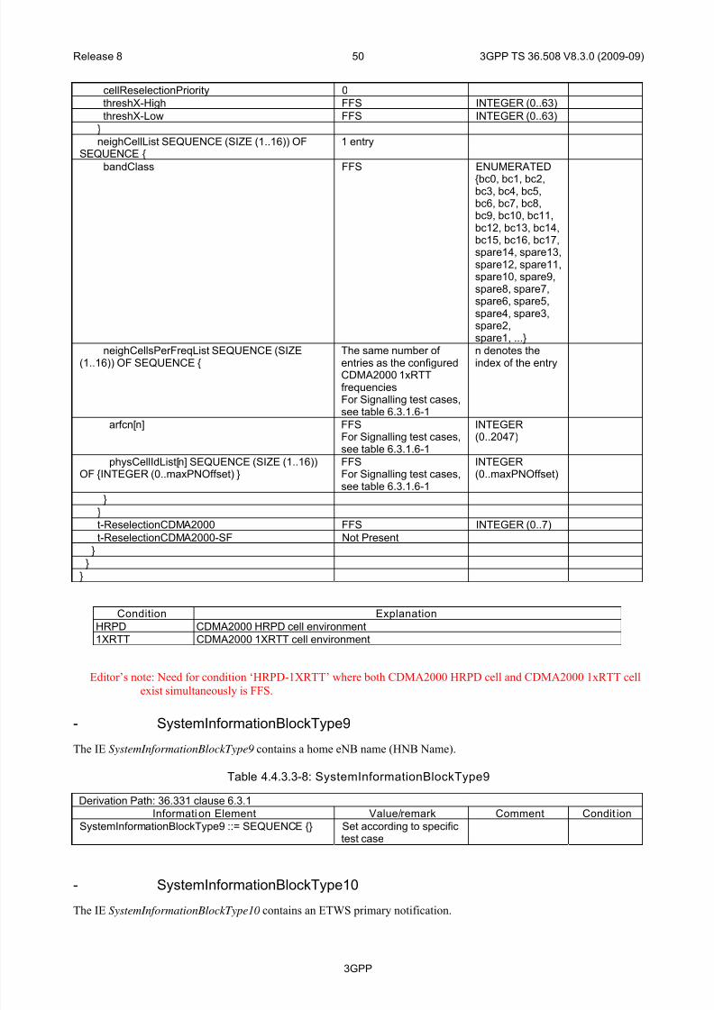
7/15/2019 Lte Sib Info
http://slidepdf.com/reader/full/lte-sib-info 50/187
3GPP
3GPP TS 36.508 V8.3.0 (2009-09)50Release 8
cellReselectionPriority 0
threshX-High FFS INTEGER (0..63)
threshX-Low FFS INTEGER (0..63)
}
neighCellList SEQUENCE (SIZE (1..16)) OFSEQUENCE {
1 entry
bandClass FFS ENUMERATED
{bc0, bc1, bc2,bc3, bc4, bc5,bc6, bc7, bc8,bc9, bc10, bc11,bc12, bc13, bc14,bc15, bc16, bc17,spare14, spare13,spare12, spare11,spare10, spare9,spare8, spare7,spare6, spare5,spare4, spare3,spare2,spare1, ...}
neighCellsPerFreqList SEQUENCE (SIZE(1..16)) OF SEQUENCE {
The same number of entries as the configuredCDMA2000 1xRTTfrequenciesFor Signalling test cases,see table 6.3.1.6-1
n denotes theindex of the entry
arfcn[n] FFSFor Signalling test cases,see table 6.3.1.6-1
INTEGER(0..2047)
physCellIdList[n] SEQUENCE (SIZE (1..16))OF {INTEGER (0..maxPNOffset) }
FFSFor Signalling test cases,see table 6.3.1.6-1
INTEGER(0..maxPNOffset)
}
}
t-ReselectionCDMA2000 FFS INTEGER (0..7)t-ReselectionCDMA2000-SF Not Present
}
}
}
Condition Explanation
HRPD CDMA2000 HRPD cell environment
1XRTT CDMA2000 1XRTT cell environment
Editor’s note: Need for condition ‘HRPD-1XRTT’ where both CDMA2000 HRPD cell and CDMA2000 1xRTT cellexist simultaneously is FFS.
- SystemInformationBlockType9
The IE SystemInformationBlockType9 contains a home eNB name (HNB Name).
Table 4.4.3.3-8: SystemInformationBlockType9
Derivation Path: 36.331 clause 6.3.1
Information Element Value/remark Comment Condit ion
SystemInformationBlockType9 ::= SEQUENCE {} Set according to specifictest case
- SystemInformationBlockType10
The IE SystemInformationBlockType10 contains an ETWS primary notification.

7/15/2019 Lte Sib Info
http://slidepdf.com/reader/full/lte-sib-info 51/187
3GPP
3GPP TS 36.508 V8.3.0 (2009-09)51Release 8
Table 4.4.3.3-9: SystemInformationBlockType10
Derivation Path: 36.331 clause 6.3.1Information Element Value/remark Comment Condit ion
SystemInformationBlockType10 ::= SEQUENCE {} Set according to specifictest case
- SystemInformationBlockType11
The IE SystemInformationBlockType11 contains an ETWS secondary notification.
Table 4.4.3.3-10: SystemInformationBlockType11
Derivation Path: 36.331 clause 6.3.1
Information Element Value/remark Comment Condit ion
SystemInformationBlockType11 ::= SEQUENCE {} Set according to specifictest case
4.4.3.4 Channel-bandwidth-dependent parameters in system information blocks
The default values of parameters in system information blocks which depend on the channel bandwidth are defined intable 4.4.3.4-1.
Table 4.4.3.4-1: Channel-bandwidth-dependent parameters
Channel bandwidthInformationElement 1.4 MHz 3 MHz 5 MHz 10 MHz 15 MHz 20MHz
Comment
SIB3periodicity
64 64 32 32 32 32
SIB4periodicity
128 128 64 64 64 64
SIB5periodicity 128 128 64 64 64 64
SIB6periodicity
128 128 64 64 64 64
SIB7periodicity
128 128 64 64 64 64
SIB8periodicity
128 128 64 64 64 64
measurementBandwidth inSIB5
mbw6 mbw15 mbw25 mbw50 mbw75 mbw100
4.4.4 Common parameters for simulated UTRA cellsThe parameters specified in this subclause apply to all simulated UTRA cells unless otherwise specified.
Default UTRA parameters for simulated cells are specified in table 4.4.4-1 and table 4.4.4-2.
Other parameters are specified in TS 34.108 [5].
Table 4.4.4-1: Default parameters fo r simulated UTRA cells
cell ID Primary scrambl ingcode for FDD
Cell parameters IDfor TDD
Cell 5 100 0
Cell 7 150 4
Cell 8 200 8Cell 9 250 12
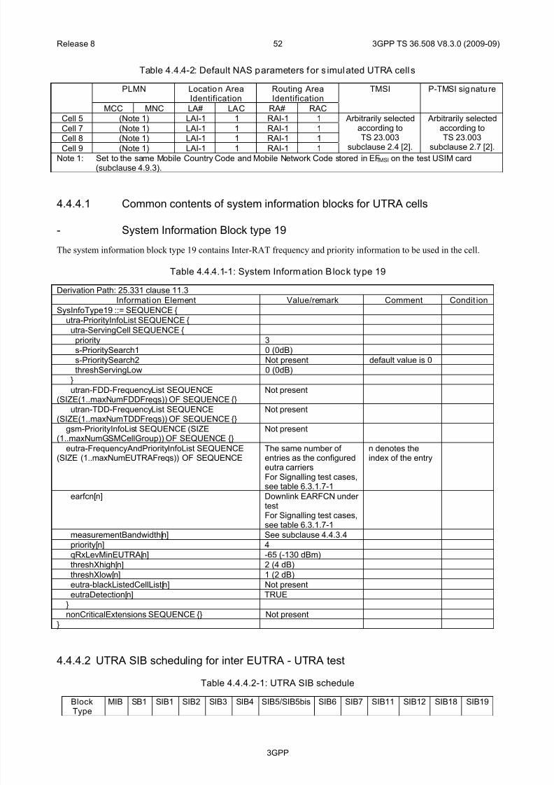
7/15/2019 Lte Sib Info
http://slidepdf.com/reader/full/lte-sib-info 52/187
3GPP
3GPP TS 36.508 V8.3.0 (2009-09)52Release 8
Table 4.4.4-2: Default NAS parameters for s imulated UTRA cells
PLMN Location AreaIdentification
Routing AreaIdentification
MCC MNC LA# LAC RA# RAC
TMSI P-TMSI signature
Cell 5 (Note 1) LAI-1 1 RAI-1 1
Cell 7 (Note 1) LAI-1 1 RAI-1 1
Cell 8 (Note 1) LAI-1 1 RAI-1 1Cell 9 (Note 1) LAI-1 1 RAI-1 1
Arbitrarily selectedaccording to
TS 23.003subclause 2.4 [2].
Arbitrarily selectedaccording to
TS 23.003subclause 2.7 [2].
Note 1: Set to the same Mobile Country Code and Mobile Network Code stored in EFIMSI on the test USIM card(subclause 4.9.3).
4.4.4.1 Common contents of system information blocks for UTRA cells
- System Information Block type 19
The system information block type 19 contains Inter-RAT frequency and priority information to be used in the cell.
Table 4.4.4.1-1: System Information B lock type 19
Derivation Path: 25.331 clause 11.3
Information Element Value/remark Comment Condit ion
SysInfoType19 ::= SEQUENCE {
utra-PriorityInfoList SEQUENCE {
utra-ServingCell SEQUENCE {
priority 3
s-PrioritySearch1 0 (0dB)
s-PrioritySearch2 Not present default value is 0
threshServingLow 0 (0dB)
}
utran-FDD-FrequencyList SEQUENCE(SIZE(1..maxNumFDDFreqs)) OF SEQUENCE {}
Not present
utran-TDD-FrequencyList SEQUENCE(SIZE(1..maxNumTDDFreqs)) OF SEQUENCE {}
Not present
gsm-PriorityInfoList SEQUENCE (SIZE(1..maxNumGSMCellGroup)) OF SEQUENCE {}
Not present
eutra-FrequencyAndPriorityInfoList SEQUENCE(SIZE (1..maxNumEUTRAFreqs)) OF SEQUENCE
The same number of entries as the configuredeutra carriersFor Signalling test cases,see table 6.3.1.7-1
n denotes theindex of the entry
earfcn[n] Downlink EARFCN under testFor Signalling test cases,see table 6.3.1.7-1
measurementBandwidth[n] See subclause 4.4.3.4
priority[n] 4qRxLevMinEUTRA[n] -65 (-130 dBm)
threshXhigh[n] 2 (4 dB)
threshXlow[n] 1 (2 dB)
eutra-blackListedCellList[n] Not present
eutraDetection[n] TRUE
}
nonCriticalExtensions SEQUENCE {} Not present
}
4.4.4.2 UTRA SIB scheduling for inter EUTRA - UTRA test
Table 4.4.4.2-1: UTRA SIB schedule
BlockType
MIB SB1 SIB1 SIB2 SIB3 SIB4 SIB5/SIB5bis SIB6 SIB7 SIB11 SIB12 SIB18 SIB19

7/15/2019 Lte Sib Info
http://slidepdf.com/reader/full/lte-sib-info 53/187
3GPP
3GPP TS 36.508 V8.3.0 (2009-09)53Release 8
SIB_REP 8 16 64 64 64 64 64 64 16 64 64 64 64
SEG_ COUNT
1 1 1 1 1 1 4 4 1 3 1 1 3
Table 4.4.4.2-2: UTRA SIB-repeat period
Frame No / SIB_POS 0 2 4 6 8 10 12 14
Block Type MIB SB1 SIB7 SIB6 MIB SIB6 SIB6 SIB6
Frame No / SIB_POS 16 18 20 22 24 26 28 30Block Type MIB SB1 SIB7/SIB3 SIB1/SIB2 MIB SIB12/SI
B19SIB19 SIB19
Frame No / SIB_POS 32 34 36 38 40 42 44 46Block Type MIB SB1 SIB7/SIB18 SIB5/
SIB5bisMIB SIB5/
SIB5bisSIB5/
SIB5bisSIB5/
SIB5bis
Frame No / SIB_POS 48 50 52 54 56 58 60 62
Block Type MIB SB1 SIB7/SIB4 - MIB SIB11 SIB11 SIB11
4.4.4.3 UTRA SIB scheduling for inter EUTRA – UTRA - GERAN test
Table 4.4.4.3-1: UTRA SIB schedule
BlockType
MIB SB1 SIB1 SIB2 SIB3 SIB4SIB5/
SIB5bisSIB7 SIB11 SIB16 SIB18 SIB19
SIB Rep 8 16 128 128 64 64 128 32 128 128 128 128
Max. No of seg.
1 2 1 1 1 1 4 1 3 8 1 3
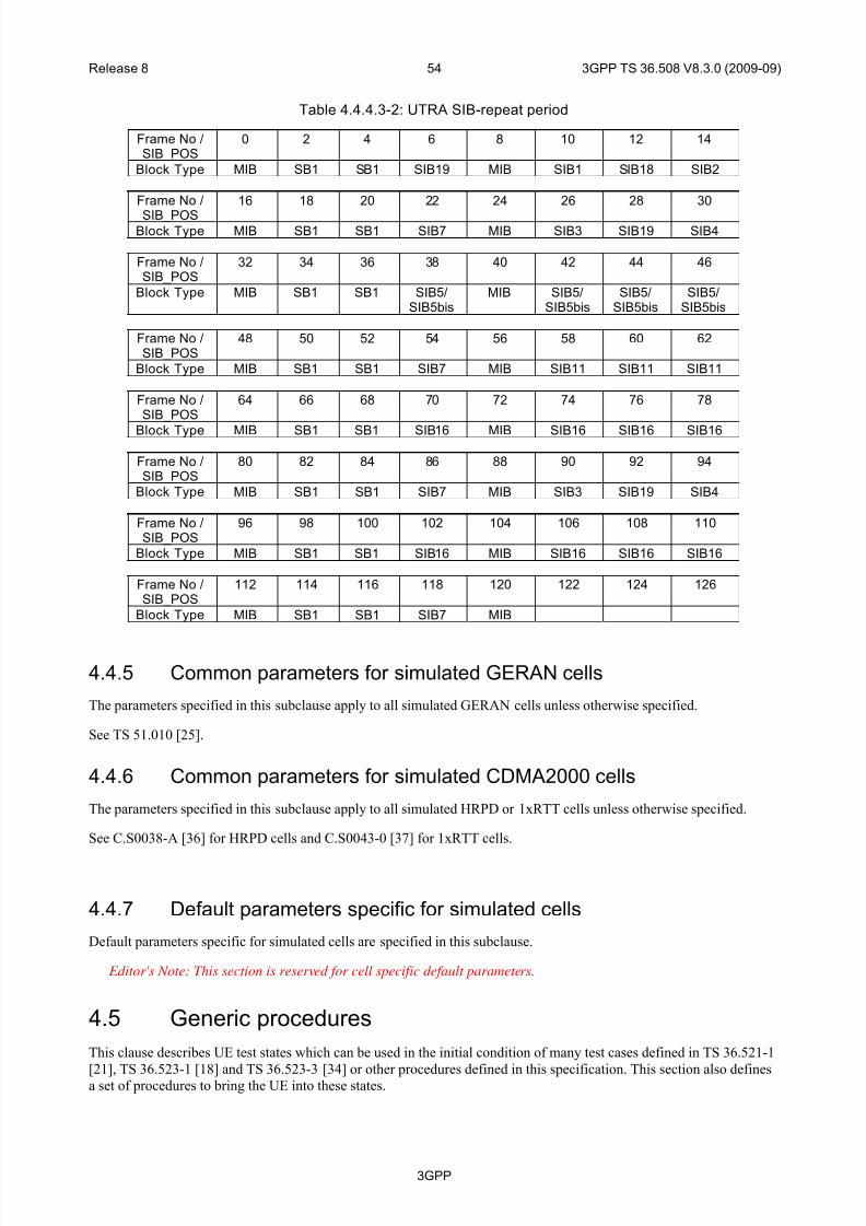
7/15/2019 Lte Sib Info
http://slidepdf.com/reader/full/lte-sib-info 54/187
3GPP
3GPP TS 36.508 V8.3.0 (2009-09)54Release 8
Table 4.4.4.3-2: UTRA SIB-repeat period
Frame No /SIB_POS
0 2 4 6 8 10 12 14
Block Type MIB SB1 SB1 SIB19 MIB SIB1 SIB18 SIB2
Frame No /
SIB_POS
16 18 20 22 24 26 28 30
Block Type MIB SB1 SB1 SIB7 MIB SIB3 SIB19 SIB4
Frame No /SIB_POS
32 34 36 38 40 42 44 46
Block Type MIB SB1 SB1 SIB5/SIB5bis
MIB SIB5/SIB5bis
SIB5/SIB5bis
SIB5/SIB5bis
Frame No /SIB_POS
48 50 52 54 56 58 60 62
Block Type MIB SB1 SB1 SIB7 MIB SIB11 SIB11 SIB11
Frame No /SIB_POS
64 66 68 70 72 74 76 78
Block Type MIB SB1 SB1 SIB16 MIB SIB16 SIB16 SIB16
Frame No /SIB_POS
80 82 84 86 88 90 92 94
Block Type MIB SB1 SB1 SIB7 MIB SIB3 SIB19 SIB4
Frame No /SIB_POS
96 98 100 102 104 106 108 110
Block Type MIB SB1 SB1 SIB16 MIB SIB16 SIB16 SIB16
Frame No /SIB_POS
112 114 116 118 120 122 124 126
Block Type MIB SB1 SB1 SIB7 MIB
4.4.5 Common parameters for simulated GERAN cells
The parameters specified in this subclause apply to all simulated GERAN cells unless otherwise specified.
See TS 51.010 [25].
4.4.6 Common parameters for simulated CDMA2000 cells
The parameters specified in this subclause apply to all simulated HRPD or 1xRTT cells unless otherwise specified.
See C.S0038-A [36] for HRPD cells and C.S0043-0 [37] for 1xRTT cells.
4.4.7 Default parameters specific for simulated cells
Default parameters specific for simulated cells are specified in this subclause.
Editor's Note: This section is reserved for cell specific default parameters.
4.5 Generic procedures
This clause describes UE test states which can be used in the initial condition of many test cases defined in TS 36.521-1
[21], TS 36.523-1 [18] and TS 36.523-3 [34] or other procedures defined in this specification. This section also definesa set of procedures to bring the UE into these states.

7/15/2019 Lte Sib Info
http://slidepdf.com/reader/full/lte-sib-info 55/187
3GPP
3GPP TS 36.508 V8.3.0 (2009-09)55Release 8
4.5.1 UE test states
NOTE: The need to have a procedure for the transition from State 4/State 3 to State 2 is for further study and itcan added if the technical motivation for this procedure can be justified.
State 1Switched OFF
State 2Registered,Idle Mode
State 3Generic RBEstablished
State 2ARegistered,Idle Mode,
UE Test Mode Activated
State 3AGeneric RB Established,UE Test Mode Activated
State 4Loopback Activated
Figure 4.5.1-1: UE Test States for Basic Generic Procedures
In order that the UE can set up a call or session in E-UTRAN, there are a number of procedures to be undertaken in ahierachical sequence to move between known states. The sequences are shown in figure 4.5.1-1 and the status of the
relevant protocols in the UE in the different states are given in table 4.5.1-1.
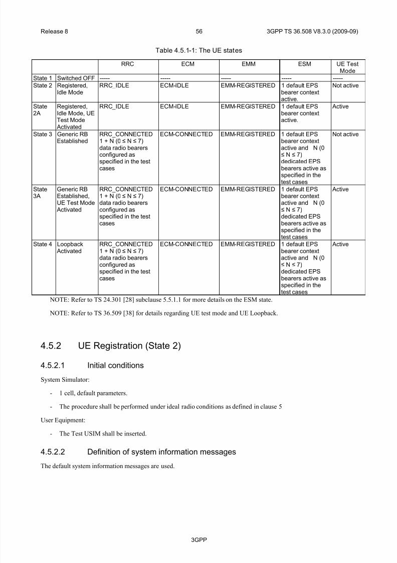
7/15/2019 Lte Sib Info
http://slidepdf.com/reader/full/lte-sib-info 56/187
3GPP
3GPP TS 36.508 V8.3.0 (2009-09)56Release 8
Table 4.5.1-1: The UE states
RRC ECM EMM ESM UE TestMode
State 1 Switched OFF ----- ----- ----- ----- -----
State 2 Registered,Idle Mode
RRC_IDLE ECM-IDLE EMM-REGISTERED 1 default EPSbearer context
active.
Not active
State2A
Registered,Idle Mode, UETest Mode Activated
RRC_IDLE ECM-IDLE EMM-REGISTERED 1 default EPSbearer contextactive.
Active
State 3 Generic RBEstablished
RRC_CONNECTED1 + N (0 ≤ N ≤ 7)data radio bearersconfigured asspecified in the testcases
ECM-CONNECTED EMM-REGISTERED 1 default EPSbearer contextactive and N (0≤ N ≤ 7)dedicated EPSbearers active asspecified in thetest cases
Not active
State
3A
Generic RB
Established,UE Test Mode Activated
RRC_CONNECTED
1 + N (0 ≤ N ≤ 7)data radio bearersconfigured asspecified in the testcases
ECM-CONNECTED EMM-REGISTERED 1 default EPS
bearer contextactive and N (0≤ N ≤ 7)dedicated EPSbearers active asspecified in thetest cases
Active
State 4 Loopback Activated
RRC_CONNECTED1 + N (0 ≤ N ≤ 7)data radio bearersconfigured asspecified in the testcases
ECM-CONNECTED EMM-REGISTERED 1 default EPSbearer contextactive and N (0≤ N ≤ 7)dedicated EPSbearers active asspecified in the
test cases
Active
NOTE: Refer to TS 24.301 [28] subclause 5.5.1.1 for more details on the ESM state.
NOTE: Refer to TS 36.509 [38] for details regarding UE test mode and UE Loopback.
4.5.2 UE Registration (State 2)
4.5.2.1 Initial conditions
System Simulator:
- 1 cell, default parameters.
- The procedure shall be performed under ideal radio conditions as defined in clause 5
User Equipment:
- The Test USIM shall be inserted.
4.5.2.2 Definition of system information messages
The default system information messages are used.

7/15/2019 Lte Sib Info
http://slidepdf.com/reader/full/lte-sib-info 57/187
3GPP
3GPP TS 36.508 V8.3.0 (2009-09)57Release 8
4.5.2.3 Procedure
Table 4.5.2.3-1: UE registration procedure (state 1 to s tate 2)
Step Procedure Message SequenceU - S Message
1 <-- RRC: SYSTEM INFORMATION (BCCH)2 UE transmits an RRCConnectionRequest message.
--> RRC: RRCConnectionRequest
3 SS transmit a RRCConnectionSetup message.
<--RRC: RRCConnectionSetup
4 The UE transmits aRRCConnectionSetupComplete message toconfirm the successful completion of theconnection establishment and to initiate the Attach procedure by including the ATTACHREQUEST message. The PDNCONNECTIVITY REQUEST message ispiggybacked in ATTACH REQUEST
--> RRC: RRCConnectionSetupComplete NAS: ATTACH REQUESTNAS: PDN CONNECTIVITY REQUEST
5 The SS transmits an AUTHENTICATIONREQUEST message to initiate the EPSauthentication and AKA procedure.
<--RRC: DLInformationTransfer NAS: AUTHENTICATION REQUEST
6 The UE transmits an AUTHENTICATIONRESPONSE message and establishes mutualauthentication.
--> RRC: ULInformationTransfer NAS: AUTHENTICATION RESPONSE
7 The SS transmits a NAS SECURITY MODECOMMAND message to activate NASsecurity.
<--RRC: DLInformationTransfer NAS: SECURITY MODE COMMAND
8 The UE transmits a NAS SECURITY MODECOMPLETE message and establishes theinitial security configuration.
--> RRC: ULInformationTransfer NAS: SECURITY MODE COMPLETE
- EXCEPTION: Steps 9a1 to 9a2 describebehaviour that depends on UE configuration;the "lower case letter" identifies a stepsequence that take place if the UE has ESM
information which needs to be transferredafter NAS SECURITY MODE COMPLETEmessage.
- -
9a1 IF the UE sets the ESM information transfer flag in the last PDN CONNECTIVITYREQUEST message THEN the SS transmitsan ESM INFORMATION REQUEST messageto initiate exchange of protocol configurationoptions.
<-- RRC: DLInformationTransfer NAS: ESM INFORMATION REQUEST
9a2 The UE transmits an ESM INFORMATIONRESPONSE message to transfer protocolconfiguration options.
--> RRC: ULInformationTransfer NAS: ESM INFORMATION RESPONSE
10 The SS transmits a SecurityModeCommand message to activate AS security.
<-- RRC: SecurityModeCommand
11 The UE transmits a SecurityModeCompletemessage and establishes the initial securityconfiguration.
--> RRC: SecurityModeComplete
12 The SS transmits an UECapabilityEnquiry message to initiate the UE radio accesscapability transfer procedure.
<-- RRC: UECapabilityEnquiry
13 The UE transmits an UECapabilityInformation message to transfer UE radio accesscapability.
--> RRC: UECapabilityInformation
14 The SS transmits aRRCConnectionReconfiguration message toestablish the default bearer with conditionSRB2-DRB(1, 0) according to 4.8.2.2.1.1.This message includes the ATTACH ACCEPT
message. The ACTIVATE DEFAULT EPSBEARER CONTEXT REQUEST message ispiggybacked in ATTACH ACCEPT.
<-- RRC: RRCConnectionReconfiguration NAS: ATTACH ACCEPTNAS: ACTIVATE DEFAULT EPSBEARER CONTEXT REQUEST
15 The UE transmits a --> RRC:
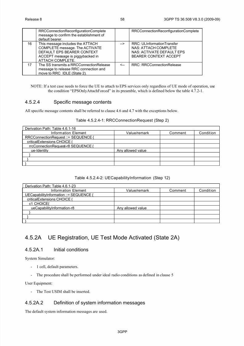
7/15/2019 Lte Sib Info
http://slidepdf.com/reader/full/lte-sib-info 58/187
3GPP
3GPP TS 36.508 V8.3.0 (2009-09)58Release 8
RRCConnectionReconfigurationCompletemessage to confirm the establishment of default bearer.
RRCConnectionReconfigurationComplete
16 This message includes the ATTACHCOMPLETE message. The ACTIVATEDEFAULT EPS BEARER CONTEXT ACCEPT message is piggybacked in
ATTACH COMPLETE.
--> RRC: ULInformationTransfer NAS: ATTACH COMPLETENAS: ACTIVATE DEFAULT EPSBEARER CONTEXT ACCEPT
17 The SS transmits a RRCConnectionRelease message to release RRC connection andmove to RRC_IDLE (State 2).
<-- RRC: RRCConnectionRelease
NOTE: If a test case needs to force the UE to attach to EPS services only regardless of UE mode of operation, usethe condition “EPSOnlyAttachForced” in its preamble, which is defined below the table 4.7.2-1.
4.5.2.4 Specific message contents
All specific message contents shall be referred to clause 4.6 and 4.7 with the exceptions below.
Table 4.5.2.4-1: RRCConnectionRequest (Step 2)
Derivation Path: Table 4.6.1-16
Information Element Value/remark Comment Condit ion
RRCConnectionRequest ::= SEQUENCE {
criticalExtensions CHOICE {
rrcConnectionRequest-r8 SEQUENCE {
ue-Identity Any allowed value
}
}
}
Table 4.5.2.4-2: UECapabilityInformation (Step 12)
Derivation Path: Table 4.6.1-23
Information Element Value/remark Comment Condit ion
UECapabilityInformation ::= SEQUENCE {
criticalExtensions CHOICE {
c1 CHOICE{
ueCapabilityInformation-r8 Any allowed value
}
}
}
4.5.2A UE Registration, UE Test Mode Activated (State 2A)4.5.2A.1 Initial conditions
System Simulator:
- 1 cell, default parameters.
- The procedure shall be performed under ideal radio conditions as defined in clause 5
User Equipment:
- The Test USIM shall be inserted.
4.5.2A.2 Definition of system information messages
The default system information messages are used.
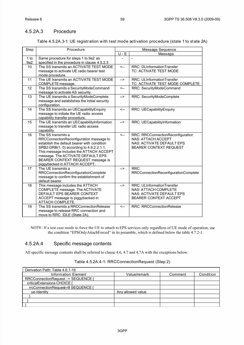
7/15/2019 Lte Sib Info
http://slidepdf.com/reader/full/lte-sib-info 59/187
3GPP
3GPP TS 36.508 V8.3.0 (2009-09)59Release 8
4.5.2A.3 Procedure
Table 4.5.2A.3-1: UE registration with test mode activation procedure (state 1 to state 2A)
Step Procedure Message SequenceU - S Message
1 to9a2 Same procedure for steps 1 to 9a2 asspecified in the procedure in clause 4.5.2.3 - -
10 The SS transmits an ACTIVATE TEST MODEmessage to activate UE radio bearer testmode procedure.
<-- RRC: DLInformationTransfer TC: ACTIVATE TEST MODE
11 The UE transmits an ACTIVATE TEST MODECOMPLETE message.
--> RRC: ULInformationTransfer TC: ACTIVATE TEST MODE COMPLETE
12 The SS transmits a SecurityModeCommand message to activate AS security.
<-- RRC: SecurityModeCommand
13 The UE transmits a SecurityModeCompletemessage and establishes the initial securityconfiguration.
--> RRC: SecurityModeComplete
14 The SS transmits an UECapabilityEnquiry message to initiate the UE radio accesscapability transfer procedure.
<-- RRC: UECapabilityEnquiry
15 The UE transmits an UECapabilityInformation message to transfer UE radio accesscapability.
--> RRC: UECapabilityInformation
16 The SS transmits aRRCConnectionReconfiguration message toestablish the default bearer with conditionSRB2-DRB(1, 0) according to 4.8.2.2.1.1.This message includes the ATTACH ACCEPTmessage. The ACTIVATE DEFAULT EPSBEARER CONTEXT REQUEST message ispiggybacked in ATTACH ACCEPT.
<-- RRC: RRCConnectionReconfiguration NAS: ATTACH ACCEPTNAS: ACTIVATE DEFAULT EPSBEARER CONTEXT REQUEST
17 The UE transmits aRRCConnectionReconfigurationCompletemessage to confirm the establishment of
default bearer.
--> RRC:RRCConnectionReconfigurationComplete
18 This message includes the ATTACHCOMPLETE message. The ACTIVATEDEFAULT EPS BEARER CONTEXT ACCEPT message is piggybacked in ATTACH COMPLETE.
--> RRC: ULInformationTransfer NAS: ATTACH COMPLETENAS: ACTIVATE DEFAULT EPSBEARER CONTEXT ACCEPT
19 The SS transmits a RRCConnectionRelease message to release RRC connection andmove to RRC_IDLE (State 2A).
<-- RRC: RRCConnectionRelease
NOTE: If a test case needs to force the UE to attach to EPS services only regardless of UE mode of operation, usethe condition “EPSOnlyAttachForced” in its preamble, which is defined below the table 4.7.2-1.
4.5.2A.4 Specific message contents
All specific message contents shall be referred to clause 4.6, 4.7 and 4.7A with the exceptions below.
Table 4.5.2A.4-1: RRCConnectionRequest (Step 2)
Derivation Path: Table 4.6.1-16
Information Element Value/remark Comment Condit ion
RRCConnectionRequest ::= SEQUENCE {
criticalExtensions CHOICE {
rrcConnectionRequest-r8 SEQUENCE {
ue-Identity Any allowed value
}
}}
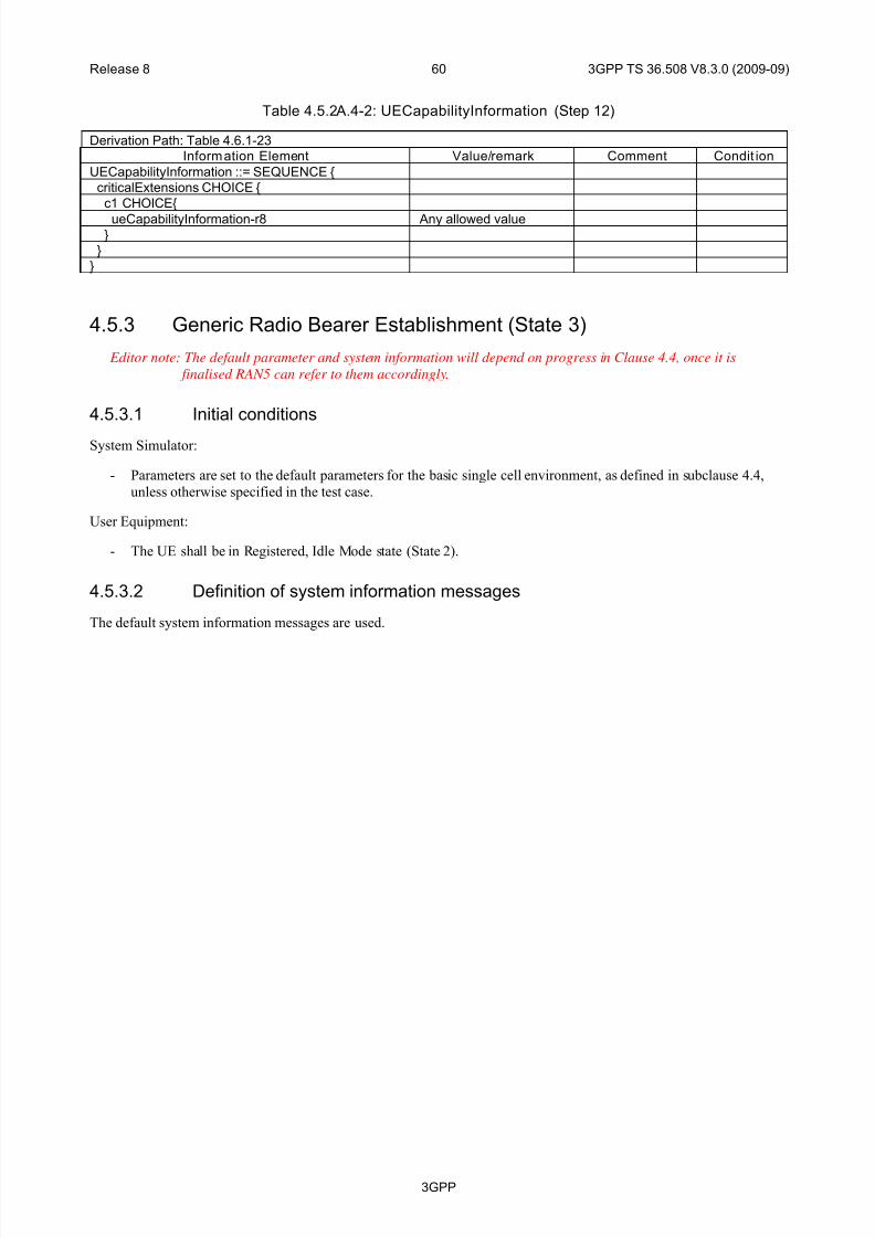
7/15/2019 Lte Sib Info
http://slidepdf.com/reader/full/lte-sib-info 60/187
3GPP
3GPP TS 36.508 V8.3.0 (2009-09)60Release 8
Table 4.5.2A.4-2: UECapabilityInformation (Step 12)
Derivation Path: Table 4.6.1-23Information Element Value/remark Comment Condit ion
UECapabilityInformation ::= SEQUENCE {
criticalExtensions CHOICE {
c1 CHOICE{
ueCapabilityInformation-r8 Any allowed value}
}
}
4.5.3 Generic Radio Bearer Establishment (State 3)
Editor note: The default parameter and system information will depend on progress in Clause 4.4, once it is
finalised RAN5 can refer to them accordingly.
4.5.3.1 Initial conditions
System Simulator:
- Parameters are set to the default parameters for the basic single cell environment, as defined in subclause 4.4,unless otherwise specified in the test case.
User Equipment:
- The UE shall be in Registered, Idle Mode state (State 2).
4.5.3.2 Definition of system information messages
The default system information messages are used.
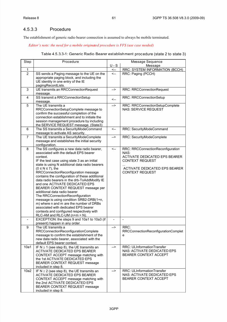
7/15/2019 Lte Sib Info
http://slidepdf.com/reader/full/lte-sib-info 61/187
3GPP
3GPP TS 36.508 V8.3.0 (2009-09)61Release 8
4.5.3.3 Procedure
The establishment of generic radio bearer connection is assumed to always be mobile terminated.
Editor’s note: the need for a mobile originated procedure is FFS (use case needed)
Table 4.5.3.3-1: Generic Radio Bearer establishment procedure (state 2 to s tate 3)Step Procedure Message Sequence
U - S Message
1 <-- RRC: SYSTEM INFORMATION (BCCH)
2 SS sends a Paging message to the UE on theappropriate paging block, and including theUE identity in one entry of the IEpagingRecordLists.
<-- RRC: Paging (PCCH)
3 UE transmits an RRCConnectionRequest message.
--> RRC: RRCConnectionRequest
4 SS transmit a RRCConnectionSetup message.
<--RRC: RRCConnectionSetup
5 The UE transmits aRRCConnectionSetupComplete message toconfirm the successful completion of theconnection establishment and to initiate thesession management procedure by includingthe SERVICE REQUEST message. (State3)
--> RRC: RRCConnectionSetupComplete NAS: SERVICE REQUEST
6 The SS transmits a SecurityModeCommand message to activate AS security.
<-- RRC: SecurityModeCommand
7 The UE transmits a SecurityModeComplete message and establishes the initial securityconfiguration.
--> RRC: SecurityModeComplete
8 The SS configures a new data radio bearer,associated with the default EPS bearer context.IF the test case using state 3 as an initialstate is using N additional data radio bearers
(0 ≤ N ≤ 7), theRRCConnectionReconfiguration messagecontains the configuration of these additionaldata radio bearers in the drb-ToAddModify IEand one ACTIVATE DEDICATED EPSBEARER CONTEXT REQUEST message per additional data radio bearer.The RRCConnectionReconfiguration message is using condition SRB2-DRB(1+n,m) where n and m are the number of DRBsassociated with dedicated EPS bearer contexts and configured respectively withRLC-AM and RLC-UM (n+m = N).
<-- RRC: RRCConnectionReconfigurationNAS: ACTIVATE DEDICATED EPS BEARERCONTEXT REQUEST...
ACTIVATE DEDICATED EPS BEARERCONTEXT REQUEST
- EXCEPTION: the steps 9 and 10a1 to 10a3 (if
present) happen in any order.
- -
9 The UE transmits aRRCConnectionReconfigurationCompletemessage to confirm the establishment of thenew data radio bearer, associated with thedefault EPS bearer context.
--> RRC:RRCConnectionReconfigurationComplete
10a1 IF N ≥ 1 (see step 8), the UE transmits an ACTIVATE DEDICATED EPS BEARERCONTEXT ACCEPT message matching withthe 1st ACTIVATE DEDICATED EPSBEARER CONTEXT REQUEST messageincluded in step 8.
--> RRC: ULInformationTransfer NAS: ACTIVATE DEDICATED EPSBEARER CONTEXT ACCEPT
10a2 IF N ≥ 2 (see step 8), the UE transmits an ACTIVATE DEDICATED EPS BEARER
CONTEXT ACCEPT message matching withthe 2nd ACTIVATE DEDICATED EPSBEARER CONTEXT REQUEST messageincluded in step 8.
--> RRC: ULInformationTransfer NAS: ACTIVATE DEDICATED EPS
BEARER CONTEXT ACCEPT
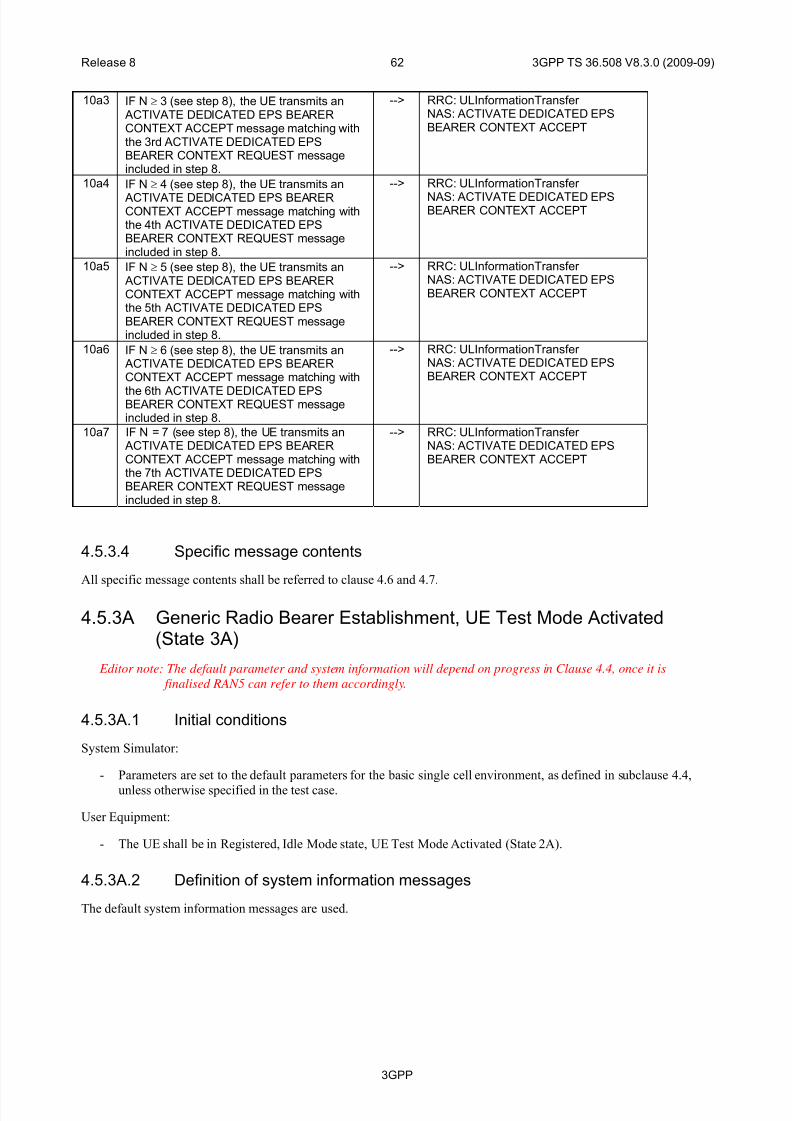
7/15/2019 Lte Sib Info
http://slidepdf.com/reader/full/lte-sib-info 62/187
3GPP
3GPP TS 36.508 V8.3.0 (2009-09)62Release 8
10a3 IF N ≥ 3 (see step 8), the UE transmits an ACTIVATE DEDICATED EPS BEARERCONTEXT ACCEPT message matching withthe 3rd ACTIVATE DEDICATED EPSBEARER CONTEXT REQUEST messageincluded in step 8.
--> RRC: ULInformationTransfer NAS: ACTIVATE DEDICATED EPSBEARER CONTEXT ACCEPT
10a4 IF N ≥ 4 (see step 8), the UE transmits an
ACTIVATE DEDICATED EPS BEARERCONTEXT ACCEPT message matching withthe 4th ACTIVATE DEDICATED EPSBEARER CONTEXT REQUEST messageincluded in step 8.
--> RRC: ULInformationTransfer
NAS: ACTIVATE DEDICATED EPSBEARER CONTEXT ACCEPT
10a5 IF N ≥ 5 (see step 8), the UE transmits an ACTIVATE DEDICATED EPS BEARERCONTEXT ACCEPT message matching withthe 5th ACTIVATE DEDICATED EPSBEARER CONTEXT REQUEST messageincluded in step 8.
--> RRC: ULInformationTransfer NAS: ACTIVATE DEDICATED EPSBEARER CONTEXT ACCEPT
10a6 IF N ≥ 6 (see step 8), the UE transmits an ACTIVATE DEDICATED EPS BEARERCONTEXT ACCEPT message matching with
the 6th ACTIVATE DEDICATED EPSBEARER CONTEXT REQUEST messageincluded in step 8.
--> RRC: ULInformationTransfer NAS: ACTIVATE DEDICATED EPSBEARER CONTEXT ACCEPT
10a7 IF N = 7 (see step 8), the UE transmits an ACTIVATE DEDICATED EPS BEARERCONTEXT ACCEPT message matching withthe 7th ACTIVATE DEDICATED EPSBEARER CONTEXT REQUEST messageincluded in step 8.
--> RRC: ULInformationTransfer NAS: ACTIVATE DEDICATED EPSBEARER CONTEXT ACCEPT
4.5.3.4 Specific message contents
All specific message contents shall be referred to clause 4.6 and 4.7.
4.5.3A Generic Radio Bearer Establishment, UE Test Mode Activated(State 3A)
Editor note: The default parameter and system information will depend on progress in Clause 4.4, once it is
finalised RAN5 can refer to them accordingly.
4.5.3A.1 Initial conditions
System Simulator:
- Parameters are set to the default parameters for the basic single cell environment, as defined in subclause 4.4,unless otherwise specified in the test case.
User Equipment:
- The UE shall be in Registered, Idle Mode state, UE Test Mode Activated (State 2A).
4.5.3A.2 Definition of system information messages
The default system information messages are used.
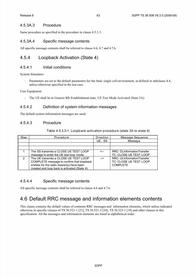
7/15/2019 Lte Sib Info
http://slidepdf.com/reader/full/lte-sib-info 63/187
3GPP
3GPP TS 36.508 V8.3.0 (2009-09)63Release 8
4.5.3A.3 Procedure
Same procedure as specified in the procedure in clause 4.5.3.3.
4.5.3A.4 Specific message contents
All specific message contents shall be referred to clause 4.6, 4.7 and 4.7A.
4.5.4 Loopback Activation (State 4)
4.5.4.1 Initial conditions
System Simulator:
- Parameters are set to the default parameters for the basic single cell environment, as defined in subclause 4.4,unless otherwise specified in the test case.
User Equipment:
- The UE shall be in Generic RB Establishment state, UE Test Mode Activated (State 3A).
4.5.4.2 Definition of system information messages
The default system information messages are used.
4.5.4.3 Procedure
Table 4.5.3.3-1: Loopback activation procedure (state 3A to state 4)
Step Procedure Direction Message Sequence
UE - SS Message
1 The SS transmits a CLOSE UE TEST LOOPmessage to enter the UE test loop mode.
<-- RRC: DLInformationTransfer TC: CLOSE UE TEST LOOP
2 The UE transmits a CLOSE UE TEST LOOPCOMPLETE message to confirm that loopbackentities for the radio bearer(s) have beencreated and loop back is activated (State 4).
--> RRC: ULInformationTransfer TC: CLOSE UE TEST LOOPCOMPLETE
4.5.4.4 Specific message contents
All specific message contents shall be referred to clause 4.6 and 4.7A.
4.6 Default RRC message and information elements contents
This clause contains the default values of common RRC messages and information elements, which unless indicatedotherwise in specific clauses of TS 36.521-1 [21], TS 36.521-3 [34], TS 36.523-1 [18] and other clauses in thisspecification. All the messages and information elements are listed in alphabetical order.

7/15/2019 Lte Sib Info
http://slidepdf.com/reader/full/lte-sib-info 64/187
3GPP
3GPP TS 36.508 V8.3.0 (2009-09)64Release 8
4.6.1 Contents of RRC messages
– CounterCheck
Table 4.6.1-0a: CounterCheck
Derivation Path: 36.331 clause 6.2.2Information Element Value/remark Comment Condit ion
CounterCheck ::= SEQUENCE {
rrc-TransactionIdentifier RRC-TransactionIdentifier-DL
criticalExtensions CHOICE {
c1 CHOICE {
counterCheck-r8 SEQUENCE {
drb-CountMSB-InfoList Set according to specificmessage content
nonCriticalExtension SEQUENCE {} Not present
}
}
}}
– CounterCheckResponse
Table 4.6.1-0b: CounterCheckResponse
Derivation Path: 36.331 clause 6.2.2
Information Element Value/remark Comment Condit ion
CounterCheckResponse ::= SEQUENCE {
rrc-TransactionIdentifier RRC-TransactionIdentifier-UL
criticalExtensions CHOICE {counterCheckResponse-r8 SEQUENCE {
drb-CountInfoList Set according to specificmessage content
nonCriticalExtension SEQUENCE {} Not checked
}
}
}
– CSFBParametersRequestCDMA2000
Table 4.6.1-1: CSFBParametersRequestCDMA2000
Derivation Path: 36.331 clause 6.2.2
Information Element Value/remark Comment Condit ion
CSFBParametersRequestCDMA2000 ::=SEQUENCE {
criticalExtensions CHOICE {
csfbParametersRequestCDMA2000-r8SEQUENCE {
nonCriticalExtension SEQUENCE {} Not checked
}
}
}
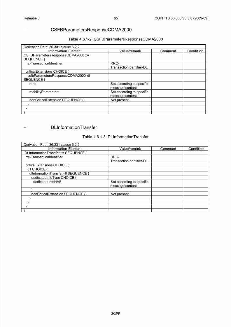
7/15/2019 Lte Sib Info
http://slidepdf.com/reader/full/lte-sib-info 65/187
3GPP
3GPP TS 36.508 V8.3.0 (2009-09)65Release 8
– CSFBParametersResponseCDMA2000
Table 4.6.1-2: CSFBParametersResponseCDMA2000
Derivation Path: 36.331 clause 6.2.2Information Element Value/remark Comment Condit ion
CSFBParametersResponseCDMA2000 ::=SEQUENCE {
rrc-TransactionIdentifier RRC-TransactionIdentifier-DL
criticalExtensions CHOICE {
csfbParametersResponseCDMA2000-r8SEQUENCE {
rand Set according to specificmessage content
mobilityParameters Set according to specificmessage content
nonCriticalExtension SEQUENCE {} Not present
}
}
}
– DLInformationTransfer
Table 4.6.1-3: DLInformationTransfer
Derivation Path: 36.331 clause 6.2.2Information Element Value/remark Comment Condit ion
DLInformationTransfer ::= SEQUENCE {
rrc-TransactionIdentifier RRC-TransactionIdentifier-DL
criticalExtensions CHOICE {
c1 CHOICE {dlInformationTransfer-r8 SEQUENCE {
dedicatedInfoType CHOICE {
dedicatedInfoNAS Set according to specificmessage content
}
nonCriticalExtension SEQUENCE {} Not present
}
}
}
}
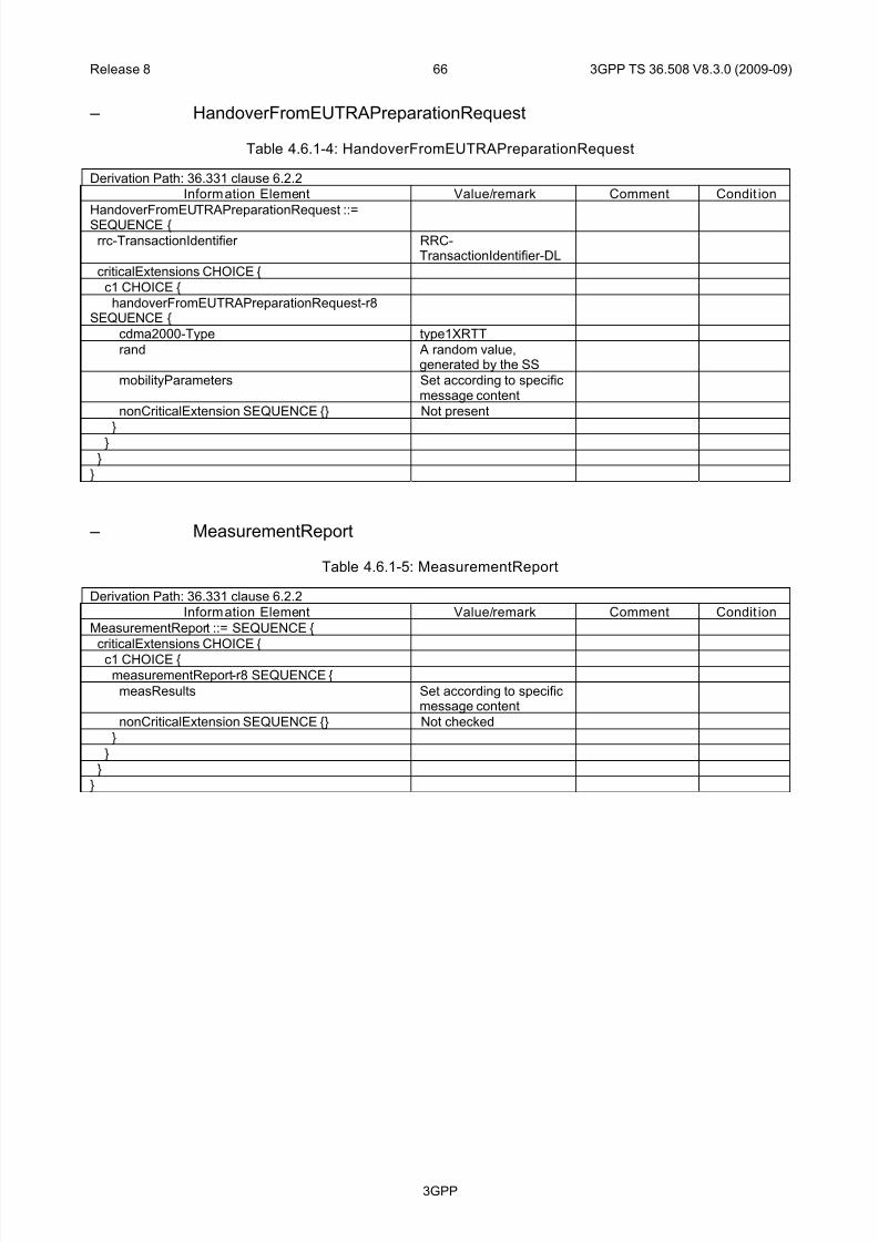
7/15/2019 Lte Sib Info
http://slidepdf.com/reader/full/lte-sib-info 66/187
3GPP
3GPP TS 36.508 V8.3.0 (2009-09)66Release 8
– HandoverFromEUTRAPreparationRequest
Table 4.6.1-4: HandoverFromEUTRAPreparationRequest
Derivation Path: 36.331 clause 6.2.2Information Element Value/remark Comment Condit ion
HandoverFromEUTRAPreparationRequest ::=SEQUENCE {
rrc-TransactionIdentifier RRC-TransactionIdentifier-DL
criticalExtensions CHOICE {
c1 CHOICE {
handoverFromEUTRAPreparationRequest-r8SEQUENCE {
cdma2000-Type type1XRTT
rand A random value,generated by the SS
mobilityParameters Set according to specificmessage content
nonCriticalExtension SEQUENCE {} Not present
}}
}
}
– MeasurementReport
Table 4.6.1-5: MeasurementReport
Derivation Path: 36.331 clause 6.2.2
Information Element Value/remark Comment Condit ion
MeasurementReport ::= SEQUENCE {
criticalExtensions CHOICE {c1 CHOICE {
measurementReport-r8 SEQUENCE {
measResults Set according to specificmessage content
nonCriticalExtension SEQUENCE {} Not checked
}
}
}
}
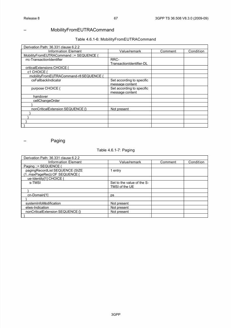
7/15/2019 Lte Sib Info
http://slidepdf.com/reader/full/lte-sib-info 67/187
3GPP
3GPP TS 36.508 V8.3.0 (2009-09)67Release 8
– MobilityFromEUTRACommand
Table 4.6.1-6: MobilityFromEUTRACommand
Derivation Path: 36.331 clause 6.2.2Information Element Value/remark Comment Condit ion
MobilityFromEUTRACommand ::= SEQUENCE {rrc-TransactionIdentifier RRC-TransactionIdentifier-DL
criticalExtensions CHOICE {
c1 CHOICE {
mobilityFromEUTRACommand-r8 SEQUENCE {
csFallbackIndicator Set according to specificmessage content
purpose CHOICE { Set according to specificmessage content
handover
cellChangeOrder
}
nonCriticalExtension SEQUENCE {} Not present
}}
}
}
– Paging
Table 4.6.1-7: Paging
Derivation Path: 36.331 clause 6.2.2
Information Element Value/remark Comment Condit ion
Paging ::= SEQUENCE {
pagingRecordList SEQUENCE (SIZE(1..maxPageRec)) OF SEQUENCE {
1 entry
ue-Identity[1] CHOICE {s-TMSI Set to the value of the S-
TMSI of the UE
}
cn-Domain[1] ps}
systemInfoModification Not present
etws-Indication Not present
nonCriticalExtension SEQUENCE {} Not present
}
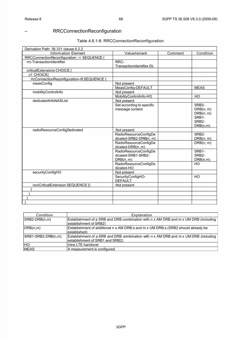
7/15/2019 Lte Sib Info
http://slidepdf.com/reader/full/lte-sib-info 68/187
3GPP
3GPP TS 36.508 V8.3.0 (2009-09)68Release 8
– RRCConnectionReconfiguration
Table 4.6.1-8: RRCConnectionReconfiguration
Derivation Path: 36.331 clause 6.2.2Information Element Value/remark Comment Condit ion
RRCConnectionReconfiguration ::= SEQUENCE {rrc-TransactionIdentifier RRC-TransactionIdentifier-DL
criticalExtensions CHOICE {
c1 CHOICE{
rrcConnectionReconfiguration-r8 SEQUENCE {
measConfig Not present
MeasConfig-DEFAULT MEAS
mobilityControlInfo Not present
MobilityControlInfo-HO HO
dedicatedInfoNASList Not present
Set according to specificmessage content
SRB2-DRB(n, m)DRB(n, m)
SRB1-SRB2-DRB(n,m)
radioResourceConfigDedicated Not present
RadioResourceConfigDedicated-SRB2-DRB(n, m)
SRB2-DRB(n, m)
RadioResourceConfigDedicated-DRB(n, m)
DRB(n, m)
RadioResourceConfigDedicated-SRB1-SRB2-DRB(n, m)
SRB1-SRB2-DRB(n,m)
RadioResourceConfigDedicated-HO
HO
securityConfigHO Not present
SecurityConfigHO-DEFAULT HO
nonCriticalExtension SEQUENCE {} Not present
}
}
}
}
Condition Explanation
SRB2-DRB(n,m) Establishment of a SRB and DRB combination with n x AM DRB and m x UM DRB (includingestablishment of SRB2)
DRB(n,m) Establishment of additional n x AM DRB:s and m x UM DRB:s (SRB2 should already beestablished)
SRB1-SRB2-DRB(n,m) Establishment of a SRB and DRB combination with n x AM DRB and m x UM DRB (includingestablishment of SRB1 and SRB2)
HO Intra LTE handover
MEAS A measurement is configured
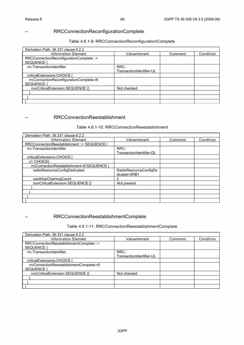
7/15/2019 Lte Sib Info
http://slidepdf.com/reader/full/lte-sib-info 69/187
3GPP
3GPP TS 36.508 V8.3.0 (2009-09)69Release 8
– RRCConnectionReconfigurationComplete
Table 4.6.1-9: RRCConnectionReconfigurationComplete
Derivation Path: 36.331 clause 6.2.2Information Element Value/remark Comment Condit ion
RRCConnectionReconfigurationComplete ::=SEQUENCE {
rrc-TransactionIdentifier RRC-TransactionIdentifier-UL
criticalExtensions CHOICE {
rrcConnectionReconfigurationComplete-r8SEQUENCE {
nonCriticalExtension SEQUENCE {} Not checked
}
}
}
– RRCConnectionReestablishment Table 4.6.1-10: RRCConnectionReestablishment
Derivation Path: 36.331 clause 6.2.2Information Element Value/remark Comment Condit ion
RRCConnectionReestablishment ::= SEQUENCE {
rrc-TransactionIdentifier RRC-TransactionIdentifier-DL
criticalExtensions CHOICE {
c1 CHOICE{
rrcConnectionReestablishment-r8 SEQUENCE {
radioResourceConfigDedicated RadioResourceConfigDedicated-SRB1
nextHopChainingCount 0nonCriticalExtension SEQUENCE {} Not present
}
}
}
}
– RRCConnectionReestablishmentComplete
Table 4.6.1-11: RRCConnectionReestablishmentComplete
Derivation Path: 36.331 clause 6.2.2
Information Element Value/remark Comment Condit ionRRCConnectionReestablishmentComplete ::=SEQUENCE {
rrc-TransactionIdentifier RRC-TransactionIdentifier-UL
criticalExtensions CHOICE {
rrcConnectionReestablishmentComplete-r8SEQUENCE {
nonCriticalExtension SEQUENCE {} Not checked
}
}
}
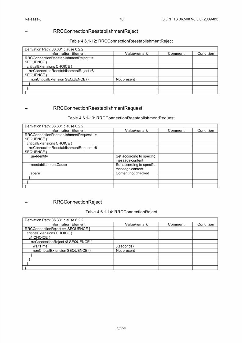
7/15/2019 Lte Sib Info
http://slidepdf.com/reader/full/lte-sib-info 70/187
3GPP
3GPP TS 36.508 V8.3.0 (2009-09)70Release 8
– RRCConnectionReestablishmentReject
Table 4.6.1-12: RRCConnectionReestablishmentReject
Derivation Path: 36.331 clause 6.2.2Information Element Value/remark Comment Condit ion
RRCConnectionReestablishmentReject ::=SEQUENCE {
criticalExtensions CHOICE {
rrcConnectionReestablishmentReject-r8SEQUENCE {
nonCriticalExtension SEQUENCE {} Not present
}
}
}
– RRCConnectionReestablishmentRequest
Table 4.6.1-13: RRCConnectionReestablishmentRequest
Derivation Path: 36.331 clause 6.2.2
Information Element Value/remark Comment Condit ion
RRCConnectionReestablishmentRequest ::=SEQUENCE {
criticalExtensions CHOICE {
rrcConnectionReestablishmentRequest-r8SEQUENCE {
ue-Identity Set according to specificmessage content
reestablishmentCause Set according to specificmessage content
spare Content not checked
}}
}
– RRCConnectionReject
Table 4.6.1-14: RRCConnectionReject
Derivation Path: 36.331 clause 6.2.2
Information Element Value/remark Comment Condit ion
RRCConnectionReject ::= SEQUENCE {
criticalExtensions CHOICE {
c1 CHOICE {rrcConnectionReject-r8 SEQUENCE {
waitTime 3(seconds)
nonCriticalExtension SEQUENCE {} Not present
}
}
}
}
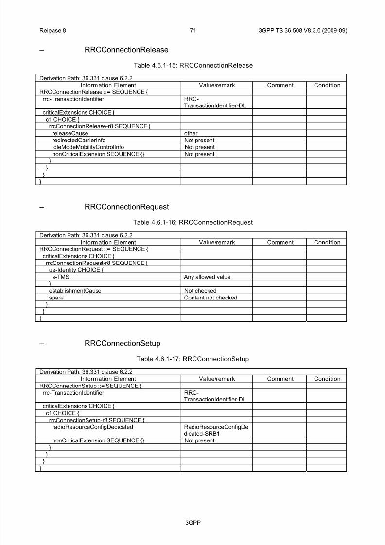
7/15/2019 Lte Sib Info
http://slidepdf.com/reader/full/lte-sib-info 71/187
3GPP
3GPP TS 36.508 V8.3.0 (2009-09)71Release 8
– RRCConnectionRelease
Table 4.6.1-15: RRCConnectionRelease
Derivation Path: 36.331 clause 6.2.2Information Element Value/remark Comment Condit ion
RRCConnectionRelease ::= SEQUENCE {rrc-TransactionIdentifier RRC-TransactionIdentifier-DL
criticalExtensions CHOICE {
c1 CHOICE {
rrcConnectionRelease-r8 SEQUENCE {
releaseCause other
redirectedCarrierInfo Not present
idleModeMobilityControlInfo Not present
nonCriticalExtension SEQUENCE {} Not present
}
}
}
}
– RRCConnectionRequest
Table 4.6.1-16: RRCConnectionRequest
Derivation Path: 36.331 clause 6.2.2
Information Element Value/remark Comment Condit ion
RRCConnectionRequest ::= SEQUENCE {
criticalExtensions CHOICE {rrcConnectionRequest-r8 SEQUENCE {
ue-Identity CHOICE {
s-TMSI Any allowed value
}establishmentCause Not checked
spare Content not checked
}
}
}
– RRCConnectionSetup
Table 4.6.1-17: RRCConnectionSetup
Derivation Path: 36.331 clause 6.2.2
Information Element Value/remark Comment Condit ionRRCConnectionSetup ::= SEQUENCE {
rrc-TransactionIdentifier RRC-TransactionIdentifier-DL
criticalExtensions CHOICE {
c1 CHOICE {
rrcConnectionSetup-r8 SEQUENCE {
radioResourceConfigDedicated RadioResourceConfigDedicated-SRB1
nonCriticalExtension SEQUENCE {} Not present
}
}
}
}
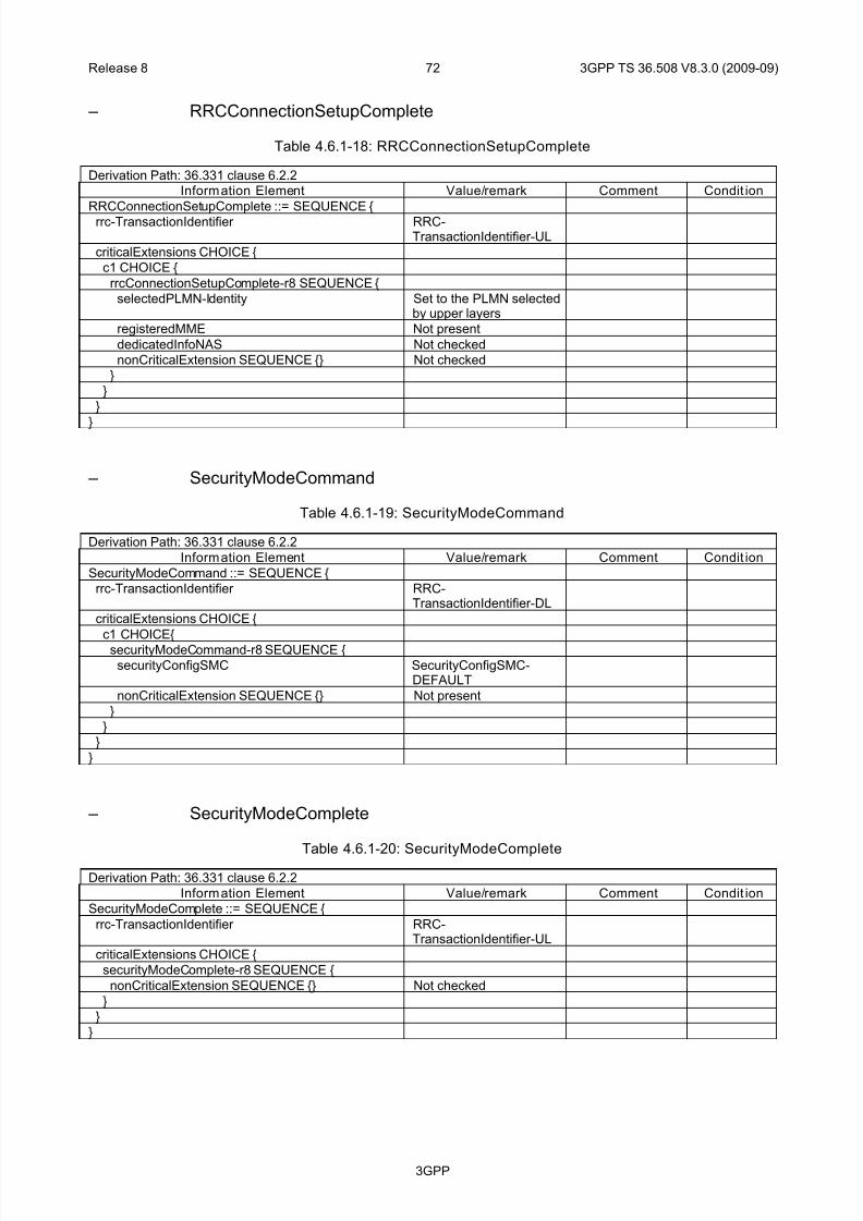
7/15/2019 Lte Sib Info
http://slidepdf.com/reader/full/lte-sib-info 72/187
3GPP
3GPP TS 36.508 V8.3.0 (2009-09)72Release 8
– RRCConnectionSetupComplete
Table 4.6.1-18: RRCConnectionSetupComplete
Derivation Path: 36.331 clause 6.2.2Information Element Value/remark Comment Condit ion
RRCConnectionSetupComplete ::= SEQUENCE {rrc-TransactionIdentifier RRC-TransactionIdentifier-UL
criticalExtensions CHOICE {
c1 CHOICE {
rrcConnectionSetupComplete-r8 SEQUENCE {
selectedPLMN-Identity Set to the PLMN selectedby upper layers
registeredMME Not present
dedicatedInfoNAS Not checked
nonCriticalExtension SEQUENCE {} Not checked
}
}
}
}
– SecurityModeCommand
Table 4.6.1-19: SecurityModeCommand
Derivation Path: 36.331 clause 6.2.2
Information Element Value/remark Comment Condit ion
SecurityModeCommand ::= SEQUENCE {
rrc-TransactionIdentifier RRC-TransactionIdentifier-DL
criticalExtensions CHOICE {
c1 CHOICE{securityModeCommand-r8 SEQUENCE {
securityConfigSMC SecurityConfigSMC-DEFAULT
nonCriticalExtension SEQUENCE {} Not present
}
}
}
}
– SecurityModeComplete
Table 4.6.1-20: SecurityModeComplete
Derivation Path: 36.331 clause 6.2.2
Information Element Value/remark Comment Condit ion
SecurityModeComplete ::= SEQUENCE {
rrc-TransactionIdentifier RRC-TransactionIdentifier-UL
criticalExtensions CHOICE {
securityModeComplete-r8 SEQUENCE {
nonCriticalExtension SEQUENCE {} Not checked
}
}
}
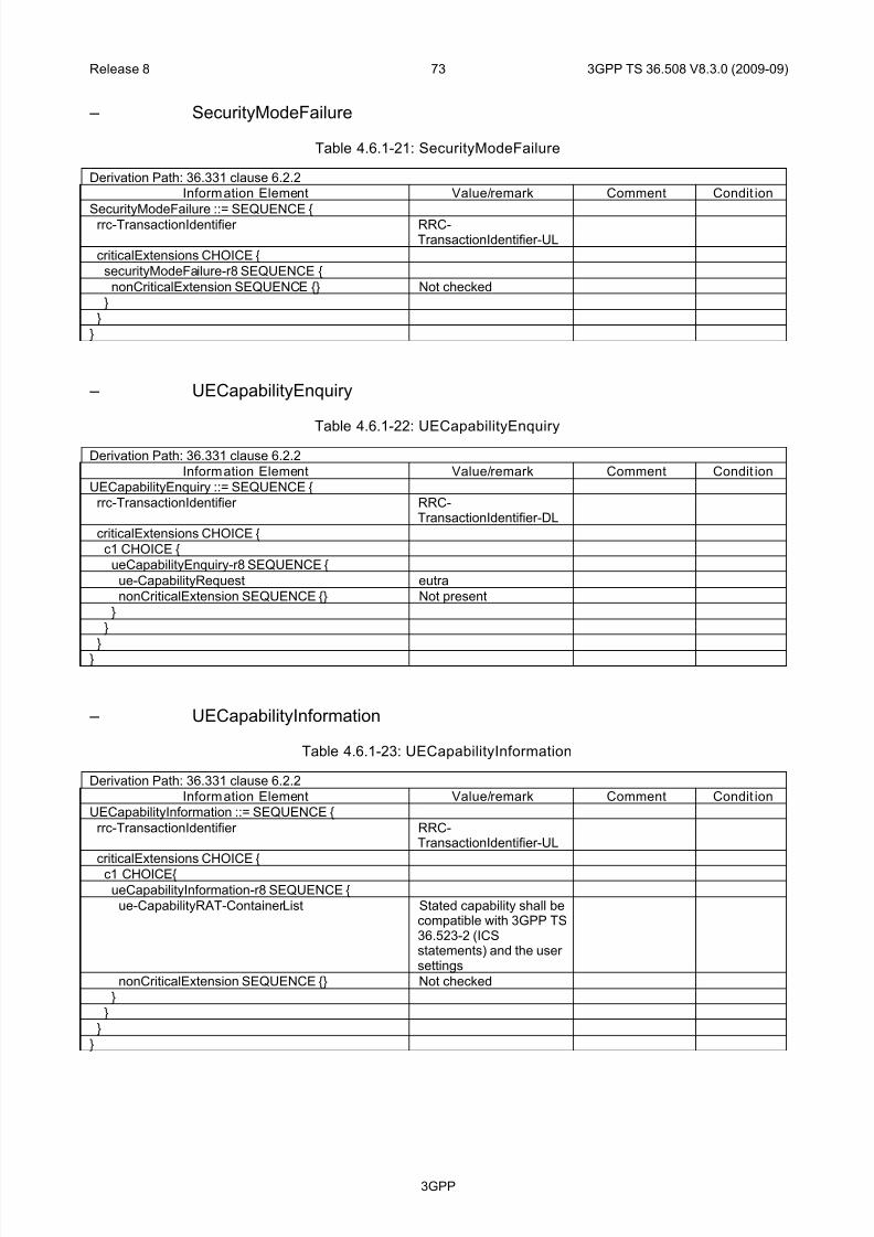
7/15/2019 Lte Sib Info
http://slidepdf.com/reader/full/lte-sib-info 73/187
3GPP
3GPP TS 36.508 V8.3.0 (2009-09)73Release 8
– SecurityModeFailure
Table 4.6.1-21: SecurityModeFailure
Derivation Path: 36.331 clause 6.2.2Information Element Value/remark Comment Condit ion
SecurityModeFailure ::= SEQUENCE {rrc-TransactionIdentifier RRC-TransactionIdentifier-UL
criticalExtensions CHOICE {
securityModeFailure-r8 SEQUENCE {
nonCriticalExtension SEQUENCE {} Not checked
}
}
}
– UECapabilityEnquiry
Table 4.6.1-22: UECapabilityEnquiry
Derivation Path: 36.331 clause 6.2.2
Information Element Value/remark Comment Condit ion
UECapabilityEnquiry ::= SEQUENCE {
rrc-TransactionIdentifier RRC-TransactionIdentifier-DL
criticalExtensions CHOICE {
c1 CHOICE {
ueCapabilityEnquiry-r8 SEQUENCE {
ue-CapabilityRequest eutra
nonCriticalExtension SEQUENCE {} Not present
}
}
}}
– UECapabilityInformation
Table 4.6.1-23: UECapabilityInformation
Derivation Path: 36.331 clause 6.2.2
Information Element Value/remark Comment Condit ion
UECapabilityInformation ::= SEQUENCE {
rrc-TransactionIdentifier RRC-TransactionIdentifier-UL
criticalExtensions CHOICE {c1 CHOICE{
ueCapabilityInformation-r8 SEQUENCE {
ue-CapabilityRAT-ContainerList Stated capability shall becompatible with 3GPP TS36.523-2 (ICSstatements) and the user settings
nonCriticalExtension SEQUENCE {} Not checked
}
}
}
}

7/15/2019 Lte Sib Info
http://slidepdf.com/reader/full/lte-sib-info 74/187
3GPP
3GPP TS 36.508 V8.3.0 (2009-09)74Release 8
- ULHandoverPreparationTransfer
Table 4.6.1-24: ULHandoverPreparationTransfer
Derivation Path: 36.331 clause 6.2.2Information Element Value/remark Comment Condit ion
ULHandoverPreparationTransfer ::= SEQUENCE {criticalExtensions CHOICE {
c1 CHOICE {
ulHandoverPreparationTransfer-r8 SEQUENCE {
cdma2000-Type type1XRTT
meid Set to the 56 bitCDMA2000 mobileidentification number of the UE
dedicatedInfo Set according to specificmessage content
nonCriticalExtension SEQUENCE {} Not checked
}
}
}}
– ULInformationTransfer
Table 4.6.1-25: ULInformationTransfer
Derivation Path: 36.331 clause 6.2.2
Information Element Value/remark Comment Condit ion
ULInformationTransfer ::= SEQUENCE {
criticalExtensions CHOICE {
c1 CHOICE {
ulInformationTransfer-r8 SEQUENCE {dedicatedInfoType CHOICE {
dedicatedInfoNAS Set according to specificmessage content
}
nonCriticalExtension SEQUENCE {} Not checked
}
}
}
}
4.6.2 System information blocks
See subclause 4.4.3.3 in this document.
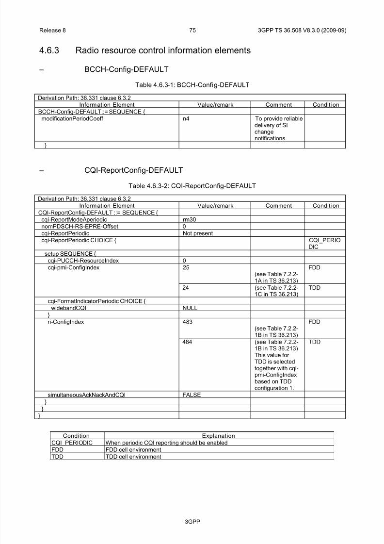
7/15/2019 Lte Sib Info
http://slidepdf.com/reader/full/lte-sib-info 75/187
3GPP
3GPP TS 36.508 V8.3.0 (2009-09)75Release 8
4.6.3 Radio resource control information elements
– BCCH-Config-DEFAULT
Table 4.6.3-1: BCCH-Config-DEFAULT
Derivation Path: 36.331 clause 6.3.2Information Element Value/remark Comment Condit ion
BCCH-Config-DEFAULT::= SEQUENCE {
modificationPeriodCoeff n4 To provide reliabledelivery of SIchangenotifications.
}
– CQI-ReportConfig-DEFAULT
Table 4.6.3-2: CQI-ReportConfig-DEFAULTDerivation Path: 36.331 clause 6.3.2
Information Element Value/remark Comment Condit ion
CQI-ReportConfig-DEFAULT ::= SEQUENCE {
cqi-ReportModeAperiodic rm30
nomPDSCH-RS-EPRE-Offset 0
cqi-ReportPeriodic Not present
cqi-ReportPeriodic CHOICE { CQI_PERIODIC
setup SEQUENCE {
cqi-PUCCH-ResourceIndex 0
cqi-pmi-ConfigIndex 25(see Table 7.2.2-
1A in TS 36.213)
FDD
24 (see Table 7.2.2-1C in TS 36.213)
TDD
cqi-FormatIndicatorPeriodic CHOICE {
widebandCQI NULL
}
ri-ConfigIndex 483(see Table 7.2.2-1B in TS 36.213)
FDD
484 (see Table 7.2.2-1B in TS 36.213)This value for TDD is selectedtogether with cqi-pmi-ConfigIndexbased on TDDconfiguration 1.
TDD
simultaneousAckNackAndCQI FALSE
}
}}
Condition Explanation
CQI_PERIODIC When periodic CQI reporting should be enabled
FDD FDD cell environment
TDD TDD cell environment
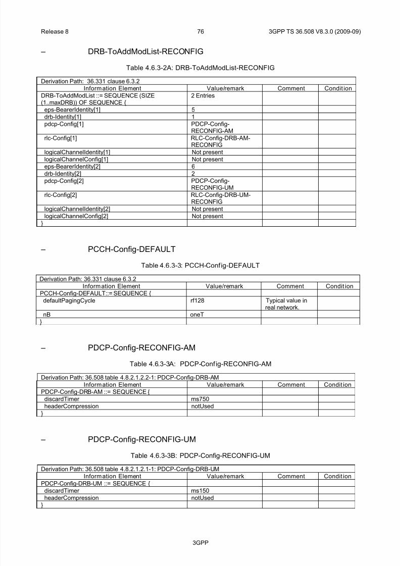
7/15/2019 Lte Sib Info
http://slidepdf.com/reader/full/lte-sib-info 76/187
3GPP
3GPP TS 36.508 V8.3.0 (2009-09)76Release 8
– DRB-ToAddModList-RECONFIG
Table 4.6.3-2A: DRB-ToAddModList-RECONFIG
Derivation Path: 36.331 clause 6.3.2Information Element Value/remark Comment Condit ion
DRB-ToAddModList ::= SEQUENCE (SIZE(1..maxDRB)) OF SEQUENCE { 2 Entries
eps-BearerIdentity[1] 5
drb-Identity[1] 1
pdcp-Config[1] PDCP-Config-RECONFIG-AM
rlc-Config[1] RLC-Config-DRB-AM-RECONFIG
logicalChannelIdentity[1] Not present
logicalChannelConfig[1] Not present
eps-BearerIdentity[2] 6
drb-Identity[2] 2
pdcp-Config[2] PDCP-Config-RECONFIG-UM
rlc-Config[2] RLC-Config-DRB-UM-RECONFIG
logicalChannelIdentity[2] Not present
logicalChannelConfig[2] Not present
}
– PCCH-Config-DEFAULT
Table 4.6.3-3: PCCH-Config-DEFAULT
Derivation Path: 36.331 clause 6.3.2
Information Element Value/remark Comment Condit ion
PCCH-Config-DEFAULT::= SEQUENCE {defaultPagingCycle rf128 Typical value in
real network.
nB oneT
}
– PDCP-Config-RECONFIG-AM
Table 4.6.3-3A: PDCP-Conf ig-RECONFIG-AM
Derivation Path: 36.508 table 4.8.2.1.2.2-1: PDCP-Config-DRB-AM
Information Element Value/remark Comment Condit ion
PDCP-Config-DRB-AM ::= SEQUENCE {discardTimer ms750
headerCompression notUsed
}
– PDCP-Config-RECONFIG-UM
Table 4.6.3-3B: PDCP-Config-RECONFIG-UM
Derivation Path: 36.508 table 4.8.2.1.2.1-1: PDCP-Config-DRB-UM
Information Element Value/remark Comment Condit ion
PDCP-Config-DRB-UM ::= SEQUENCE {
discardTimer ms150headerCompression notUsed
}
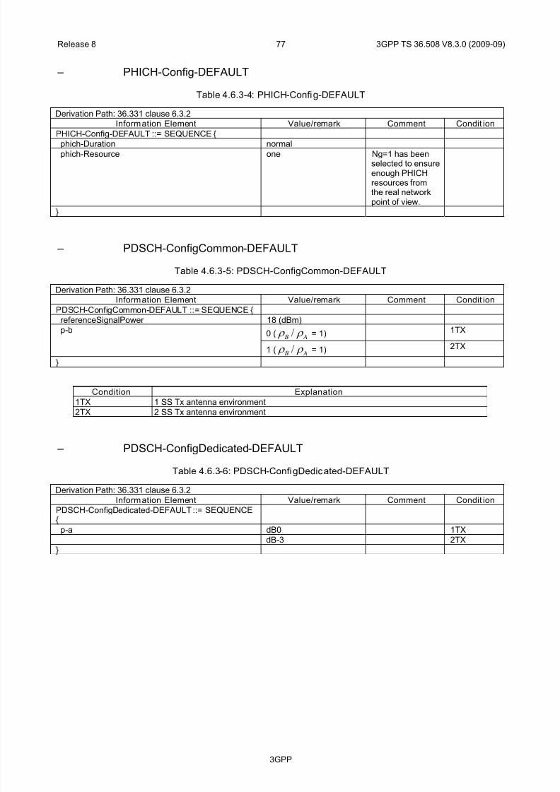
7/15/2019 Lte Sib Info
http://slidepdf.com/reader/full/lte-sib-info 77/187
3GPP
3GPP TS 36.508 V8.3.0 (2009-09)77Release 8
– PHICH-Config-DEFAULT
Table 4.6.3-4: PHICH-Config-DEFAULT
Derivation Path: 36.331 clause 6.3.2Information Element Value/remark Comment Condit ion
PHICH-Config-DEFAULT ::= SEQUENCE {phich-Duration normal
phich-Resource one Ng=1 has beenselected to ensureenough PHICHresources fromthe real networkpoint of view.
}
– PDSCH-ConfigCommon-DEFAULT
Table 4.6.3-5: PDSCH-ConfigCommon-DEFAULTDerivation Path: 36.331 clause 6.3.2
Information Element Value/remark Comment Condit ion
PDSCH-ConfigCommon-DEFAULT ::= SEQUENCE {
referenceSignalPower 18 (dBm)
p-b 0 ( A B ρ ρ / = 1) 1TX
1 ( A B ρ ρ / = 1) 2TX
}
Condition Explanation
1TX 1 SS Tx antenna environment
2TX 2 SS Tx antenna environment
– PDSCH-ConfigDedicated-DEFAULT
Table 4.6.3-6: PDSCH-ConfigDedicated-DEFAULT
Derivation Path: 36.331 clause 6.3.2
Information Element Value/remark Comment Condit ion
PDSCH-ConfigDedicated-DEFAULT ::= SEQUENCE{
p-a dB0 1TX
dB-3 2TX
}

7/15/2019 Lte Sib Info
http://slidepdf.com/reader/full/lte-sib-info 78/187
3GPP
3GPP TS 36.508 V8.3.0 (2009-09)78Release 8
– PRACH-Config-DEFAULT
Table 4.6.3-7: PRACH-Config-DEFAULT
Derivation Path: 36.331 clause 6.3.2Information Element Value/remark Comment Condit ion
PRACH-Config-DEFAULT ::= SEQUENCE {rootSequenceIndex 22 Corresponding tou = 1 (See table5.7.2-4 in TS36.211for PRACHformat 0-3)
FDD
0 Corresponding tou = 1 (See table5.7.2-5 in TS36.211 for PRACH format 4)
TDD
prach-ConfigInfo SEQUENCE {
prach-ConfigIndex 3 Typical value inreal network for FDD (see table5.7.1-1 and 5.7.1-2 in TS 36.211)
FDD
51 Typical value inreal network for TDD (see table5.7.1-3 and 5.7.1-4 in TS 36.211)
TDD
highSpeedFlag FALSE (Unrestricted set) High speed trainconfigurationdoesn’t apply bydefault.
zeroCorrelationZoneConfig 5 (Ncs configuration = 5) Assuming cellradius is up toapproximately 3
km.
FDD
4 (Ncs configuration = 4) Assuming cellradius is up toapproximately 1km.
TDD
prach-FreqOffset See subclause 4.6.8 Channel-bandwidth-dependentparameter
}
}
Note: Although PRACH format 0-3 is applicable for both FDD and TDD, the PRACH format 4 is used as default for testing for TDD.
Condition Explanation
FDD FDD cell environment
TDD TDD cell environment
– PRACH-ConfigSIB-DEFAULT
Table 4.6.3-7a: PRACH-ConfigSIB-DEFAULT
Derivation Path: 36.508 clause 4.6.3 Table 4.6.3-7 PRACH-Config-DEFAULT

7/15/2019 Lte Sib Info
http://slidepdf.com/reader/full/lte-sib-info 79/187
3GPP
3GPP TS 36.508 V8.3.0 (2009-09)79Release 8
– PUCCH-ConfigCommon-DEFAULT
Table 4.6.3-8: PUCCH-ConfigCommon-DEFAULT
Derivation Path: 36.331 clause 6.3.2Information Element Value/remark Comment Condit ion
PUCCH-ConfigCommon-DEFAULT ::= SEQUENCE {deltaPUCCH-Shift ds2 Assuming typicalvalues of themaximum delayspread
nRB-CQI See subclause 4.6.8 Channel-bandwidth-dependentparameter
nCS-AN 6
n1PUCCH-AN 0
}
– PUCCH-ConfigDedicated-DEFAULT
Table 4.6.3-9: PUCCH-ConfigDedicated-DEFAULT
Derivation Path: 36.331 clause 6.3.2Information Element Value/remark Comment Condit ion
PUCCH-ConfigDedicated-DEFAULT ::= SEQUENCE{
ackNackRepetition CHOICE {
release NULL
}
tddAckNackFeedbackMode Not present FDD
multiplexing Multiplexing is
selected asdefault to alignwith RAN4’sassumptions inRF tests.
TDD
}
Condition Explanation
FDD FDD cell environment
TDD TDD cell environment
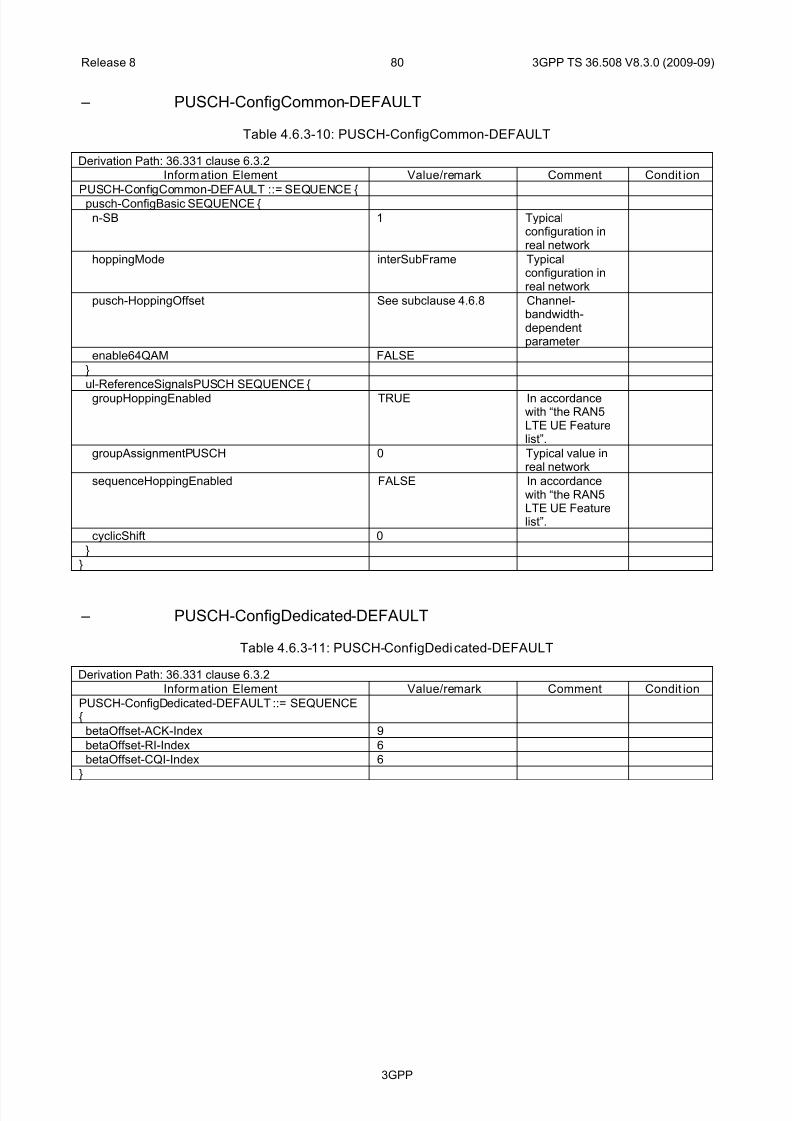
7/15/2019 Lte Sib Info
http://slidepdf.com/reader/full/lte-sib-info 80/187
3GPP
3GPP TS 36.508 V8.3.0 (2009-09)80Release 8
– PUSCH-ConfigCommon-DEFAULT
Table 4.6.3-10: PUSCH-ConfigCommon-DEFAULT
Derivation Path: 36.331 clause 6.3.2Information Element Value/remark Comment Condit ion
PUSCH-ConfigCommon-DEFAULT ::= SEQUENCE {pusch-ConfigBasic SEQUENCE {
n-SB 1 Typicalconfiguration inreal network
hoppingMode interSubFrame Typicalconfiguration inreal network
pusch-HoppingOffset See subclause 4.6.8 Channel-bandwidth-dependentparameter
enable64QAM FALSE
}
ul-ReferenceSignalsPUSCH SEQUENCE {groupHoppingEnabled TRUE In accordancewith “the RAN5LTE UE Featurelist”.
groupAssignmentPUSCH 0 Typical value inreal network
sequenceHoppingEnabled FALSE In accordancewith “the RAN5LTE UE Featurelist”.
cyclicShift 0
}
}
– PUSCH-ConfigDedicated-DEFAULT
Table 4.6.3-11: PUSCH-ConfigDedicated-DEFAULT
Derivation Path: 36.331 clause 6.3.2
Information Element Value/remark Comment Condit ion
PUSCH-ConfigDedicated-DEFAULT ::= SEQUENCE{
betaOffset-ACK-Index 9
betaOffset-RI-Index 6
betaOffset-CQI-Index 6
}

7/15/2019 Lte Sib Info
http://slidepdf.com/reader/full/lte-sib-info 81/187
3GPP
3GPP TS 36.508 V8.3.0 (2009-09)81Release 8
– RACH-ConfigCommon-DEFAULT
Table 4.6.3-12: RACH-ConfigCommon-DEFAULT
Derivation Path: 36.331 clause 6.3.2Information Element Value/remark Comment Condit ion
RACH-ConfigCommon-DEFAULT ::= SEQUENCE {preambleInfo SEQUENCE {
numberOfRA-Preambles n52 Assuming thenumber of dedicatedpreambles is 12.
preamblesGroupAConfig SEQUENCE {} Not present
}
powerRampingParameters SEQUENCE {
powerRampingStep dB2
preambleInitialReceivedTargetPower dBm-104 (default) Thermal noise = -113 dBmNF = 5 dBIoT = 6 dBRequired SNR = -8 dB (See table8.4.2-1 in TS36.104 [30])-> -110 dB(default value isacceptable)
}
ra-SupervisionInfo SEQUENCE {
preambleTransMax n6 Under thecondition of Case1 in RAN1simulationassumptions, an
UE with pathlossof CDF = 90%reaches themaximum transmitpower in 4successiveretransmissions.6 has beenselectedconsidering themargin of 2.
ra-ResponseWindowSize sf10 The maximumvalue ispreferable.
mac-ContentionResolutionTimer sf48 Allows for asufficient number of msg3retransmissions.
}
maxHARQ-Msg3Tx 4 Under thecondition of TargetSIR = 2 dB, theprobability of 2transmissions isless than 1%. 4has been selectedconsidering themargin of 2.
}
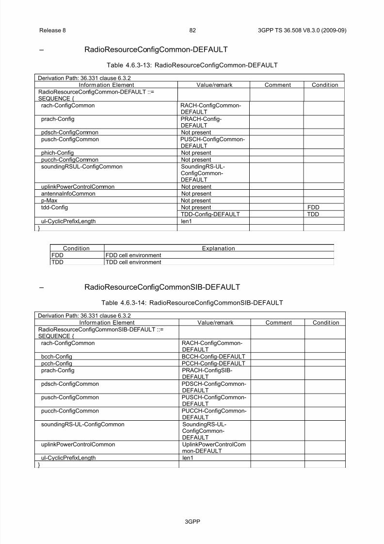
7/15/2019 Lte Sib Info
http://slidepdf.com/reader/full/lte-sib-info 82/187
3GPP
3GPP TS 36.508 V8.3.0 (2009-09)82Release 8
– RadioResourceConfigCommon-DEFAULT
Table 4.6.3-13: RadioResourceConfigCommon-DEFAULT
Derivation Path: 36.331 clause 6.3.2Information Element Value/remark Comment Condit ion
RadioResourceConfigCommon-DEFAULT ::=SEQUENCE {
rach-ConfigCommon RACH-ConfigCommon-DEFAULT
prach-Config PRACH-Config-DEFAULT
pdsch-ConfigCommon Not present
pusch-ConfigCommon PUSCH-ConfigCommon-DEFAULT
phich-Config Not present
pucch-ConfigCommon Not present
soundingRSUL-ConfigCommon SoundingRS-UL-ConfigCommon-DEFAULT
uplinkPowerControlCommon Not presentantennaInfoCommon Not present
p-Max Not present
tdd-Config Not present FDD
TDD-Config-DEFAULT TDD
ul-CyclicPrefixLength len1
}
Condition Explanation
FDD FDD cell environment
TDD TDD cell environment
– RadioResourceConfigCommonSIB-DEFAULT
Table 4.6.3-14: RadioResourceConfigCommonSIB-DEFAULT
Derivation Path: 36.331 clause 6.3.2
Information Element Value/remark Comment Condit ion
RadioResourceConfigCommonSIB-DEFAULT ::=SEQUENCE {
rach-ConfigCommon RACH-ConfigCommon-DEFAULT
bcch-Config BCCH-Config-DEFAULT
pcch-Config PCCH-Config-DEFAULT
prach-Config PRACH-ConfigSIB-
DEFAULTpdsch-ConfigCommon PDSCH-ConfigCommon-
DEFAULT
pusch-ConfigCommon PUSCH-ConfigCommon-DEFAULT
pucch-ConfigCommon PUCCH-ConfigCommon-DEFAULT
soundingRS-UL-ConfigCommon SoundingRS-UL-ConfigCommon-DEFAULT
uplinkPowerControlCommon UplinkPowerControlCommon-DEFAULT
ul-CyclicPrefixLength len1
}
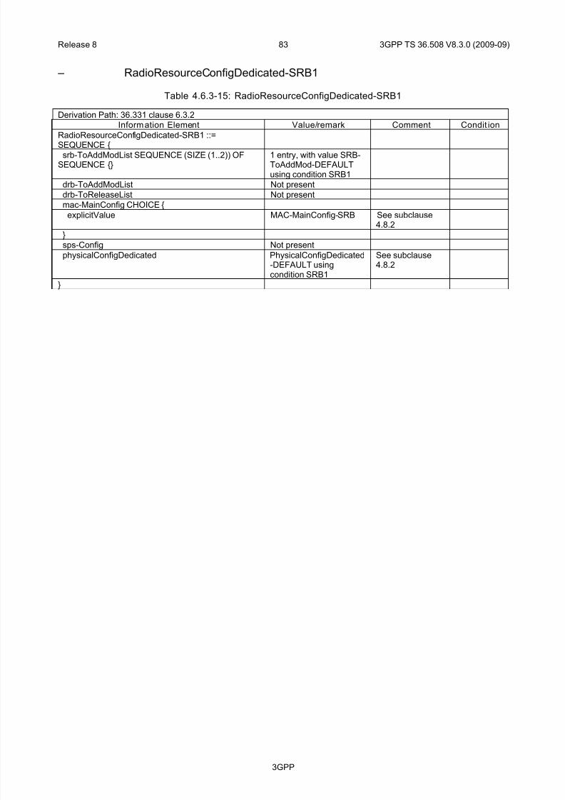
7/15/2019 Lte Sib Info
http://slidepdf.com/reader/full/lte-sib-info 83/187
3GPP
3GPP TS 36.508 V8.3.0 (2009-09)83Release 8
– RadioResourceConfigDedicated-SRB1
Table 4.6.3-15: RadioResourceConfigDedicated-SRB1
Derivation Path: 36.331 clause 6.3.2Information Element Value/remark Comment Condit ion
RadioResourceConfigDedicated-SRB1 ::=SEQUENCE {
srb-ToAddModList SEQUENCE (SIZE (1..2)) OFSEQUENCE {}
1 entry, with value SRB-ToAddMod-DEFAULTusing condition SRB1
drb-ToAddModList Not present
drb-ToReleaseList Not present
mac-MainConfig CHOICE {
explicitValue MAC-MainConfig-SRB See subclause4.8.2
}
sps-Config Not present
physicalConfigDedicated PhysicalConfigDedicated-DEFAULT using
condition SRB1
See subclause4.8.2
}
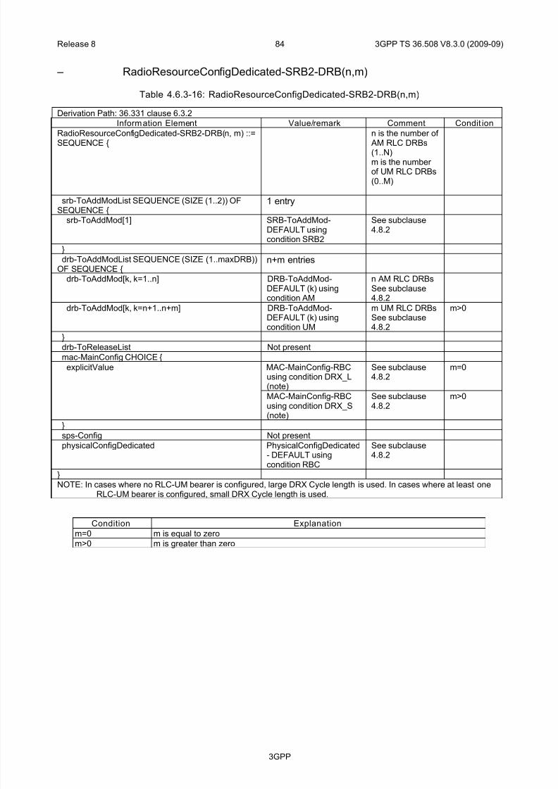
7/15/2019 Lte Sib Info
http://slidepdf.com/reader/full/lte-sib-info 84/187
3GPP
3GPP TS 36.508 V8.3.0 (2009-09)84Release 8
– RadioResourceConfigDedicated-SRB2-DRB(n,m)
Table 4.6.3-16: RadioResourceConfigDedicated-SRB2-DRB(n,m)
Derivation Path: 36.331 clause 6.3.2Information Element Value/remark Comment Condit ion
RadioResourceConfigDedicated-SRB2-DRB(n, m) ::=SEQUENCE { n is the number of AM RLC DRBs(1..N)m is the number of UM RLC DRBs(0..M)
srb-ToAddModList SEQUENCE (SIZE (1..2)) OFSEQUENCE {
1 entry
srb-ToAddMod[1] SRB-ToAddMod-DEFAULT usingcondition SRB2
See subclause4.8.2
}
drb-ToAddModList SEQUENCE (SIZE (1..maxDRB))OF SEQUENCE {
n+m entries
drb-ToAddMod[k, k=1..n] DRB-ToAddMod-DEFAULT (k) usingcondition AM
n AM RLC DRBsSee subclause4.8.2
drb-ToAddMod[k, k=n+1..n+m] DRB-ToAddMod-DEFAULT (k) usingcondition UM
m UM RLC DRBsSee subclause4.8.2
m>0
}
drb-ToReleaseList Not present
mac-MainConfig CHOICE {
explicitValue MAC-MainConfig-RBCusing condition DRX_L(note)
See subclause4.8.2
m=0
MAC-MainConfig-RBCusing condition DRX_S(note)
See subclause4.8.2
m>0
}
sps-Config Not present
physicalConfigDedicated PhysicalConfigDedicated- DEFAULT usingcondition RBC
See subclause4.8.2
}
NOTE: In cases where no RLC-UM bearer is configured, large DRX Cycle length is used. In cases where at least oneRLC-UM bearer is configured, small DRX Cycle length is used.
Condition Explanation
m=0 m is equal to zero
m>0 m is greater than zero
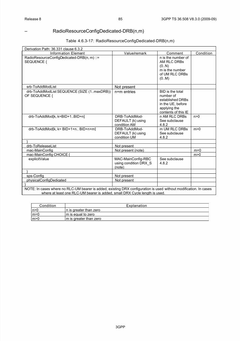
7/15/2019 Lte Sib Info
http://slidepdf.com/reader/full/lte-sib-info 85/187
3GPP
3GPP TS 36.508 V8.3.0 (2009-09)85Release 8
– RadioResourceConfigDedicated-DRB(n,m)
Table 4.6.3-17: RadioResourceConfigDedicated-DRB(n,m)
Derivation Path: 36.331 clause 6.3.2Information Element Value/remark Comment Condit ion
RadioResourceConfigDedicated-DRB(n, m) ::=SEQUENCE { n is the number of AM RLC DRBs(0..N)m is the number of UM RLC DRBs(0..M)
srb-ToAddModList Not present drb-ToAddModList SEQUENCE (SIZE (1..maxDRB))
OF SEQUENCE {n+m entries BID is the total
number of established DRBsin the UE, beforeapplying thecontents of this IE
drb-ToAddMod[k, k=BID+1..BID+n] DRB-ToAddMod-DEFAULT (k) usingcondition AM
n AM RLC DRBsSee subclause4.8.2
n>0
drb-ToAddMod[k, k= BID+1+n.. BID+n+m] DRB-ToAddMod-DEFAULT (k) usingcondition UM
m UM RLC DRBsSee subclause4.8.2
m>0
}
drb-ToReleaseList Not present
mac-MainConfig Not present (note) m=0
mac-MainConfig CHOICE { m>0
explicitValue MAC-MainConfig-RBCusing condition DRX_S(note)
See subclause4.8.2
}
sps-Config Not presentphysicalConfigDedicated Not present
}
NOTE: In cases where no RLC-UM bearer is added, existing DRX configuration is used without modification. In caseswhere at least one RLC-UM bearer is added, small DRX Cycle length is used.
Condition Explanation
n>0 n is greater than zero
m=0 m is equal to zero
m>0 m is greater than zero
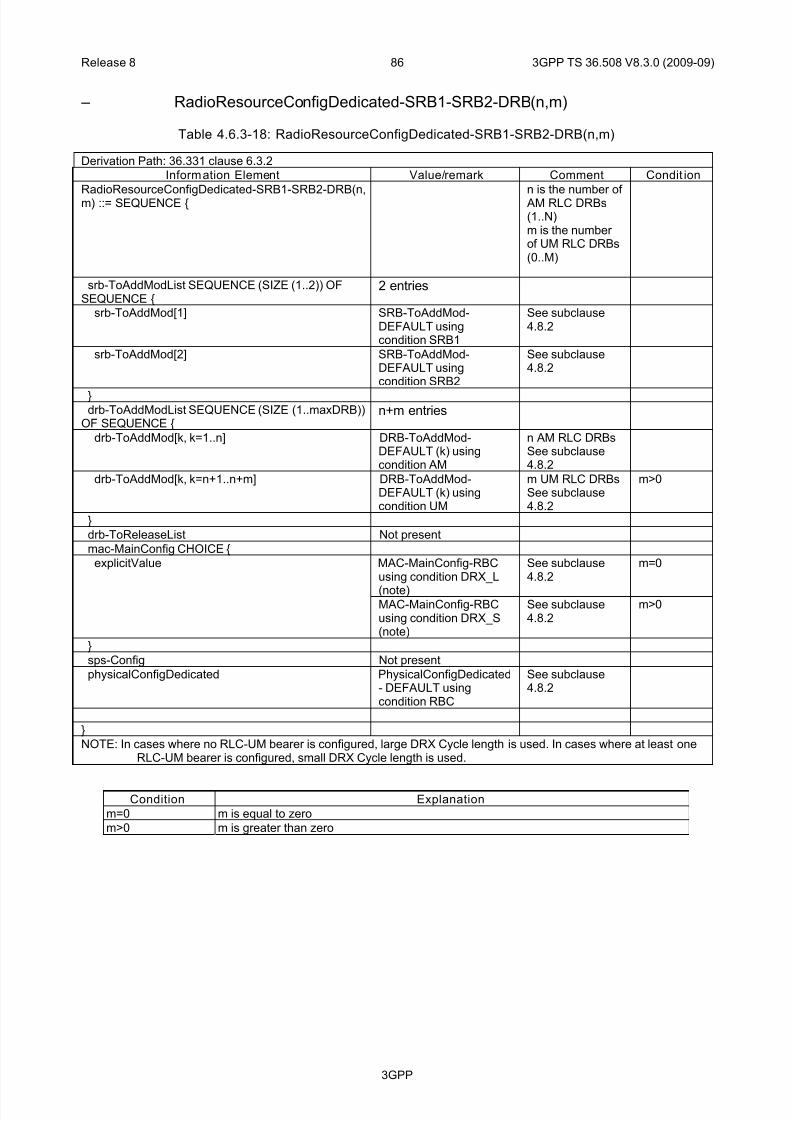
7/15/2019 Lte Sib Info
http://slidepdf.com/reader/full/lte-sib-info 86/187
3GPP
3GPP TS 36.508 V8.3.0 (2009-09)86Release 8
– RadioResourceConfigDedicated-SRB1-SRB2-DRB(n,m)
Table 4.6.3-18: RadioResourceConfigDedicated-SRB1-SRB2-DRB(n,m)
Derivation Path: 36.331 clause 6.3.2Information Element Value/remark Comment Condit ion
RadioResourceConfigDedicated-SRB1-SRB2-DRB(n,m) ::= SEQUENCE { n is the number of AM RLC DRBs(1..N)m is the number of UM RLC DRBs(0..M)
srb-ToAddModList SEQUENCE (SIZE (1..2)) OFSEQUENCE {
2 entries
srb-ToAddMod[1] SRB-ToAddMod-DEFAULT usingcondition SRB1
See subclause4.8.2
srb-ToAddMod[2] SRB-ToAddMod-DEFAULT usingcondition SRB2
See subclause4.8.2
}
drb-ToAddModList SEQUENCE (SIZE (1..maxDRB))OF SEQUENCE {
n+m entries
drb-ToAddMod[k, k=1..n] DRB-ToAddMod-DEFAULT (k) usingcondition AM
n AM RLC DRBsSee subclause4.8.2
drb-ToAddMod[k, k=n+1..n+m] DRB-ToAddMod-DEFAULT (k) usingcondition UM
m UM RLC DRBsSee subclause4.8.2
m>0
}
drb-ToReleaseList Not present
mac-MainConfig CHOICE {
explicitValue MAC-MainConfig-RBCusing condition DRX_L(note)
See subclause4.8.2
m=0
MAC-MainConfig-RBCusing condition DRX_S(note)
See subclause4.8.2
m>0
}
sps-Config Not present
physicalConfigDedicated PhysicalConfigDedicated- DEFAULT usingcondition RBC
See subclause4.8.2
}
NOTE: In cases where no RLC-UM bearer is configured, large DRX Cycle length is used. In cases where at least oneRLC-UM bearer is configured, small DRX Cycle length is used.
Condition Explanation
m=0 m is equal to zero
m>0 m is greater than zero

7/15/2019 Lte Sib Info
http://slidepdf.com/reader/full/lte-sib-info 87/187
3GPP
3GPP TS 36.508 V8.3.0 (2009-09)87Release 8
– RadioResourceConfigDedicated-HO
Table 4.6.3-19: RadioResourceConfigDedicated-HO
Derivation Path: 36.331 clause 6.3.2Information Element Value/remark Comment Condit ion
RadioResourceConfigDedicated-HO ::= SEQUENCE{
srb-ToAddModList Not present
drb-ToAddModList Not present
drb-ToReleaseList Not present
mac-MainConfig Not present
sps-Config Not present
physicalConfigDedicated PhysicalConfigDedicated-DEFAULT usingcondition RBC
See subclause4.8.2
}
– RLC-Config-DRB-AM-RECONFIGTable 4.6.3-19A: RLC-Config-DRB-AM-RECONFIG
Derivation Path: 36.508 table 4.8.2.1.3.2-1: RLC-Config-DRB-AMInformation Element Value/remark Comment Condit ion
RLC-Config-DRB-AM-RECONFIG ::= CHOICE {
am SEQUENCE {
ul-AM-RLC SEQUENCE {
t-PollRetransmit ms855
pollPDU p64
pollByte kB250
maxRetxThreshold t8
}
dl-AM-RLC SEQUENCE {t-Reordering ms85
t-StatusProhibit ms50
}
}
}
– RLC-Config-DRB-UM-RECONFIG
Table 4.6.3-19B: RLC-Config-DRB-UM-RECONFIG
Derivation Path: 36.508 table 4.8.2.1.3.1-1: RLC-Config-DRB-UM
Information Element Value/remark Comment Condit ionRLC-Config-DRB-UM-RECONFIG ::= CHOICE {
um-Bi-Directional SEQUENCE {
ul-UM-RLC SEQUENCE {
sn-FieldLength Size10
}dl-UM-RLC SEQUENCE {
sn-FieldLength Size10
t-Reordering ms55
}
}
}

7/15/2019 Lte Sib Info
http://slidepdf.com/reader/full/lte-sib-info 88/187
3GPP
3GPP TS 36.508 V8.3.0 (2009-09)88Release 8
– RLC-Config-SRB-AM-RECONFIG
Table 4.6.3-19C: RLC-Config-SRB-AM-RECONFIG
Derivation Path: 36.331 clause 6.3.2, 9.2.1Information Element Value/remark Comment Condit ion
RLC-Config-SRB-AM-RECONFIG ::= CHOICE {am SEQUENCE {
ul-AM-RLC SEQUENCE {
t-PollRetransmit ms50
pollPDU pInfinity Default
pollByte kBinfinity Default
maxRetxThreshold t6
}
dl-AM-RLC SEQUENCE {
t-Reordering ms40
t –StatusProhibit ms0 Default}
}
}
– SchedulingRequest-Config-DEFAULT
Table 4.6.3-20: SchedulingRequest-Config-DEFAULT
Derivation Path: 36.331 clause 6.3.2
Information Element Value/remark Comment Condit ion
SchedulingRequest-Config-DEFAULT ::= CHOICE {
setup SEQUENCE {
sr-PUCCH-ResourceIndex See subclause 4.6.8 Channel-bandwidth-dependent
parameter sr-ConfigIndex 30
dsr-TransMax n4
}
}
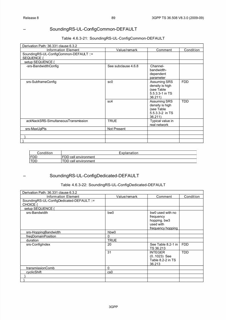
7/15/2019 Lte Sib Info
http://slidepdf.com/reader/full/lte-sib-info 89/187
3GPP
3GPP TS 36.508 V8.3.0 (2009-09)89Release 8
– SoundingRS-UL-ConfigCommon-DEFAULT
Table 4.6.3-21: SoundingRS-UL-ConfigCommon-DEFAULT
Derivation Path: 36.331 clause 6.3.2Information Element Value/remark Comment Condit ion
SoundingRS-UL-ConfigCommon-DEFAULT ::=SEQUENCE {
setup SEQUENCE {
-srs-BandwidthConfig See subclause 4.6.8 Channel-bandwidth-dependentparameter
srs-SubframeConfig sc0 Assuming SRSdensity is high(see Table5.5.3.3-1 in TS36.211)
FDD
sc4 Assuming SRSdensity is high(see Table5.5.3.3-2 in TS36.211)
TDD
ackNackSRS-SimultaneousTransmission TRUE Typical value inreal network
srs-MaxUpPts Not Present
}
}
Condition Explanation
FDD FDD cell environment
TDD TDD cell environment
– SoundingRS-UL-ConfigDedicated-DEFAULT
Table 4.6.3-22: SoundingRS-UL-ConfigDedicated-DEFAULT
Derivation Path: 36.331 clause 6.3.2
Information Element Value/remark Comment Condit ion
SoundingRS-UL-ConfigDedicated-DEFAULT ::=CHOICE {
setup SEQUENCE {
srs-Bandwidth bw0 bw0 used with nofrequencyhopping. bw3used withfrequency hopping
srs-HoppingBandwidth hbw0
freqDomainPosition 0
duration TRUE
srs-ConfigIndex 20 See Table 8.2-1 inTS 36.213
FDD
31 INTEGER(0..1023) SeeTable 8.2-2 in TS36.213
TDD
transmissionComb 0
cyclicShift cs0
}
}
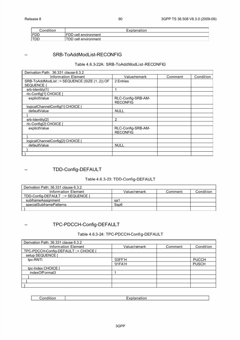
7/15/2019 Lte Sib Info
http://slidepdf.com/reader/full/lte-sib-info 90/187
3GPP
3GPP TS 36.508 V8.3.0 (2009-09)90Release 8
Condition Explanation
FDD FDD cell environment
TDD TDD cell environment
– SRB-ToAddModList-RECONFIG
Table 4.6.3-22A: SRB-ToAddModList-RECONFIG
Derivation Path: 36.331 clause 6.3.2
Information Element Value/remark Comment Condit ion
SRB-ToAddModList ::= SEQUENCE (SIZE (1..2)) OFSEQUENCE {
2 Entries
srb-Identity[1] 1
rlc-Config[1] CHOICE {
explicitValue RLC-Config-SRB-AM-RECONFIG
logicalChannelConfig[1] CHOICE {
defaultValue NULL
}
srb-Identity[2] 2
rlc-Config[2] CHOICE {
explicitValue RLC-Config-SRB-AM-RECONFIG
}
logicalChannelConfig[2] CHOICE {
defaultValue NULL
}
}
– TDD-Config-DEFAULT
Table 4.6.3-23: TDD-Config-DEFAULT
Derivation Path: 36.331 clause 6.3.2
Information Element Value/remark Comment Condit ion
TDD-Config-DEFAULT ::= SEQUENCE {
subframeAssignment sa1
specialSubframePatterns Ssp6
}
– TPC-PDCCH-Config-DEFAULT
Table 4.6.3-24: TPC-PDCCH-Config-DEFAULTDerivation Path: 36.331 clause 6.3.2
Information Element Value/remark Comment Condit ion
TPC-PDCCH-Config-DEFAULT ::= CHOICE {
setup SEQUENCE {
tpc-RNTI ‘03FF’H PUCCH
‘01FA’H PUSCH
tpc-Index CHOICE {
indexOfFormat3 1
}
}
}
Condition Explanation
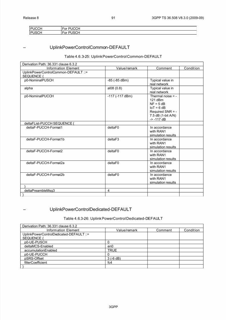
7/15/2019 Lte Sib Info
http://slidepdf.com/reader/full/lte-sib-info 91/187
3GPP
3GPP TS 36.508 V8.3.0 (2009-09)91Release 8
PUCCH For PUCCH
PUSCH For PUSCH
– UplinkPowerControlCommon-DEFAULT
Table 4.6.3-25: UplinkPowerControlCommon-DEFAULT
Derivation Path: 36.331 clause 6.3.2
Information Element Value/remark Comment Condit ion
UplinkPowerControlCommon-DEFAULT ::=SEQUENCE {
p0-NominalPUSCH -85 (-85 dBm) Typical value inreal network
alpha al08 (0.8) Typical value inreal network
p0-NominalPUCCH -117 (-117 dBm) Thermal noise = -121 dBmNF = 5 dBIoT = 6 dB
Required SNR = -7.5 dB (1-bit A/N)-> -117 dB
deltaFList-PUCCH SEQUENCE {
deltaF-PUCCH-Format1 deltaF0 In accordancewith RAN1simulation results
deltaF-PUCCH-Format1b deltaF3 In accordancewith RAN1simulation results
deltaF-PUCCH-Format2 deltaF0 In accordancewith RAN1simulation results
deltaF-PUCCH-Format2a deltaF0 In accordance
with RAN1simulation results
deltaF-PUCCH-Format2b deltaF0 In accordancewith RAN1simulation results
}
deltaPreambleMsg3 4
}
– UplinkPowerControlDedicated-DEFAULT
Table 4.6.3-26: UplinkPowerControlDedicated-DEFAULT
Derivation Path: 36.331 clause 6.3.2
Information Element Value/remark Comment Condit ion
UplinkPowerControlDedicated-DEFAULT ::=SEQUENCE {
p0-UE-PUSCH 0
deltaMCS-Enabled en0
accumulationEnabled TRUE
p0-UE-PUCCH 0
pSRS-Offset 3 (-6 dB)
filterCoefficient fc4}
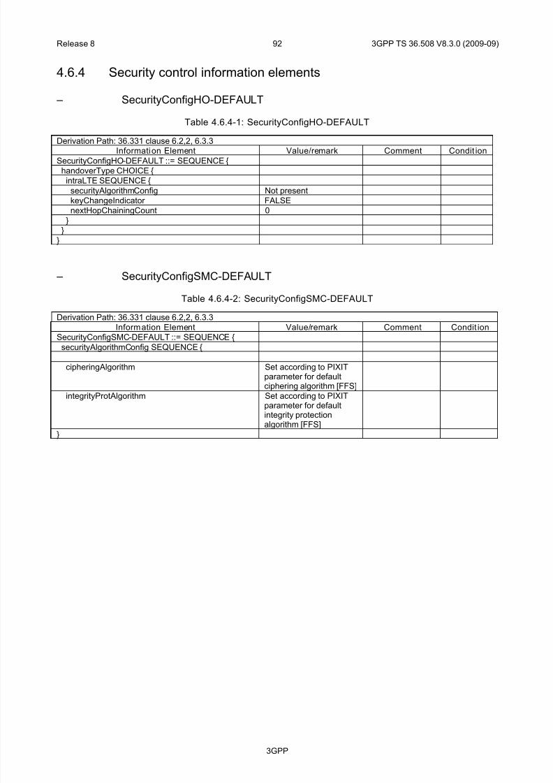
7/15/2019 Lte Sib Info
http://slidepdf.com/reader/full/lte-sib-info 92/187
3GPP
3GPP TS 36.508 V8.3.0 (2009-09)92Release 8
4.6.4 Security control information elements
– SecurityConfigHO-DEFAULT
Table 4.6.4-1: SecurityConfigHO-DEFAULT
Derivation Path: 36.331 clause 6.2,2, 6.3.3Information Element Value/remark Comment Condit ion
SecurityConfigHO-DEFAULT ::= SEQUENCE {
handoverType CHOICE {
intraLTE SEQUENCE {
securityAlgorithmConfig Not present
keyChangeIndicator FALSE
nextHopChainingCount 0
}
}
}
– SecurityConfigSMC-DEFAULT
Table 4.6.4-2: SecurityConfigSMC-DEFAULT
Derivation Path: 36.331 clause 6.2,2, 6.3.3
Information Element Value/remark Comment Condit ion
SecurityConfigSMC-DEFAULT ::= SEQUENCE {
securityAlgorithmConfig SEQUENCE {
cipheringAlgorithm Set according to PIXITparameter for defaultciphering algorithm [FFS]
integrityProtAlgorithm Set according to PIXIT
parameter for defaultintegrity protectionalgorithm [FFS]
}
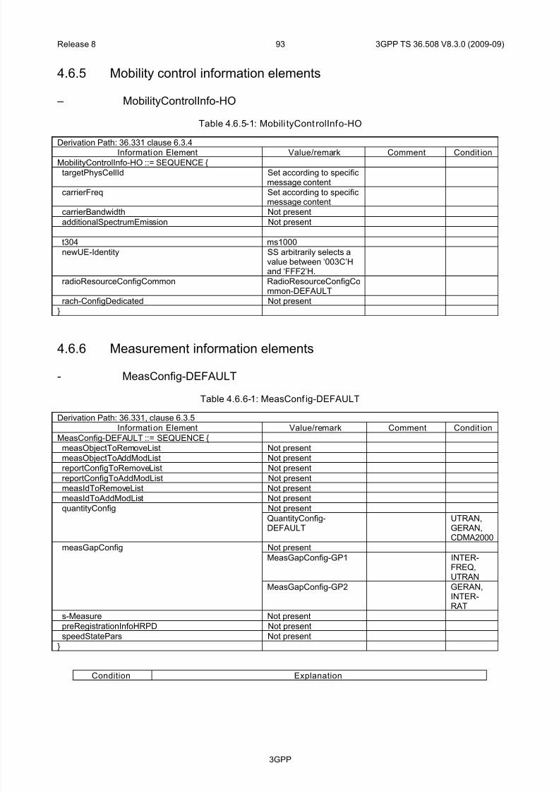
7/15/2019 Lte Sib Info
http://slidepdf.com/reader/full/lte-sib-info 93/187
3GPP
3GPP TS 36.508 V8.3.0 (2009-09)93Release 8
4.6.5 Mobility control information elements
– MobilityControlInfo-HO
Table 4.6.5-1: Mobi lityControlInfo-HO
Derivation Path: 36.331 clause 6.3.4Information Element Value/remark Comment Condit ion
MobilityControlInfo-HO ::= SEQUENCE {
targetPhysCellId Set according to specificmessage content
carrierFreq Set according to specificmessage content
carrierBandwidth Not present
additionalSpectrumEmission Not present
t304 ms1000
newUE-Identity SS arbitrarily selects avalue between ‘003C’H
and ‘FFF2’H.radioResourceConfigCommon RadioResourceConfigCommon-DEFAULT
rach-ConfigDedicated Not present
}
4.6.6 Measurement information elements
- MeasConfig-DEFAULT
Table 4.6.6-1: MeasConfig-DEFAULT
Derivation Path: 36.331, clause 6.3.5
Information Element Value/remark Comment Condit ion
MeasConfig-DEFAULT ::= SEQUENCE {
measObjectToRemoveList Not present
measObjectToAddModList Not present
reportConfigToRemoveList Not present
reportConfigToAddModList Not present
measIdToRemoveList Not present
measIdToAddModList Not present
quantityConfig Not present
QuantityConfig-DEFAULT
UTRAN,GERAN,CDMA2000
measGapConfig Not presentMeasGapConfig-GP1 INTER-FREQ,UTRAN
MeasGapConfig-GP2 GERAN,INTER-RAT
s-Measure Not present
preRegistrationInfoHRPD Not present
speedStatePars Not present
}
Condition Explanation
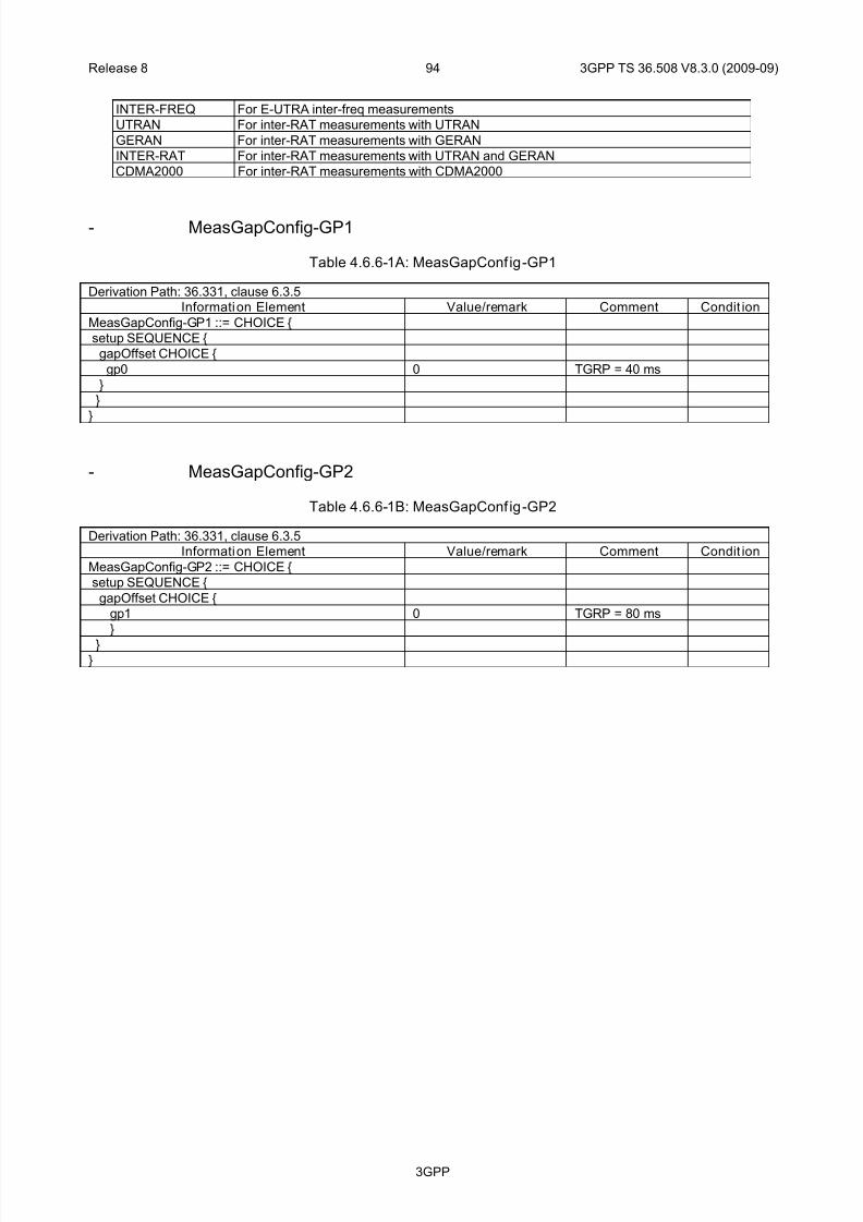
7/15/2019 Lte Sib Info
http://slidepdf.com/reader/full/lte-sib-info 94/187
3GPP
3GPP TS 36.508 V8.3.0 (2009-09)94Release 8
INTER-FREQ For E-UTRA inter-freq measurements
UTRAN For inter-RAT measurements with UTRAN
GERAN For inter-RAT measurements with GERAN
INTER-RAT For inter-RAT measurements with UTRAN and GERAN
CDMA2000 For inter-RAT measurements with CDMA2000
- MeasGapConfig-GP1
Table 4.6.6-1A: MeasGapConfig-GP1
Derivation Path: 36.331, clause 6.3.5Information Element Value/remark Comment Condit ion
MeasGapConfig-GP1 ::= CHOICE {
setup SEQUENCE {
gapOffset CHOICE {
gp0 0 TGRP = 40 ms
}
}
}
- MeasGapConfig-GP2
Table 4.6.6-1B: MeasGapConfig-GP2
Derivation Path: 36.331, clause 6.3.5Information Element Value/remark Comment Condit ion
MeasGapConfig-GP2 ::= CHOICE {
setup SEQUENCE {
gapOffset CHOICE {
gp1 0 TGRP = 80 ms
}
}
}
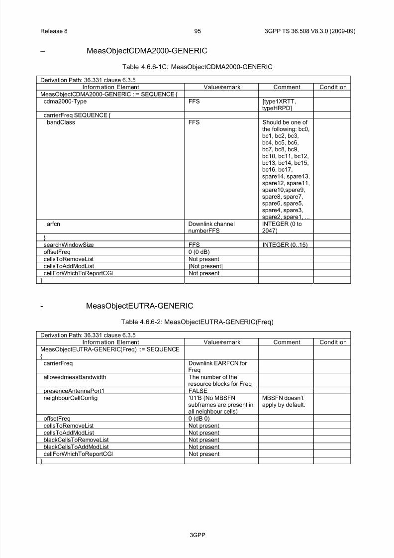
7/15/2019 Lte Sib Info
http://slidepdf.com/reader/full/lte-sib-info 95/187
3GPP
3GPP TS 36.508 V8.3.0 (2009-09)95Release 8
– MeasObjectCDMA2000-GENERIC
Table 4.6.6-1C: MeasObjectCDMA2000-GENERIC
Derivation Path: 36.331 clause 6.3.5Information Element Value/remark Comment Condit ion
MeasObjectCDMA2000-GENERIC ::= SEQUENCE {cdma2000-Type FFS [type1XRTT,typeHRPD]
carrierFreq SEQUENCE {
bandClass FFS Should be one of the following: bc0,bc1, bc2, bc3,bc4, bc5, bc6,bc7, bc8, bc9,bc10, bc11, bc12,bc13, bc14, bc15,bc16, bc17,spare14, spare13,spare12, spare11,spare10,spare9,spare8, spare7,spare6, spare5,spare4, spare3,spare2, spare1, ...
arfcn Downlink channelnumberFFS
INTEGER (0 to2047)
}
searchWindowSize FFS INTEGER (0..15)
offsetFreq 0 (0 dB)
cellsToRemoveList Not present
cellsToAddModList [Not present]
cellForWhichToReportCGI Not present
}
- MeasObjectEUTRA-GENERIC
Table 4.6.6-2: MeasObjectEUTRA-GENERIC(Freq)
Derivation Path: 36.331 clause 6.3.5Information Element Value/remark Comment Condit ion
MeasObjectEUTRA-GENERIC(Freq) ::= SEQUENCE{
carrierFreq Downlink EARFCN for Freq
allowedmeasBandwidth The number of theresource blocks for Freq
presenceAntennaPort1 FALSE
neighbourCellConfig '01'B (No MBSFNsubframes are present inall neighbour cells)
MBSFN doesn’tapply by default.
offsetFreq 0 (dB 0)
cellsToRemoveList Not present
cellsToAddModList Not present
blackCellsToRemoveList Not present
blackCellsToAddModList Not present
cellForWhichToReportCGI Not present
}

7/15/2019 Lte Sib Info
http://slidepdf.com/reader/full/lte-sib-info 96/187
3GPP
3GPP TS 36.508 V8.3.0 (2009-09)96Release 8
- MeasObjectGERAN-GENERIC
Table 4.6.6-2A: MeasObjectGERAN-GENERIC(Freq)
Derivation Path: 36.331 clause 6.3.5Information Element Value/remark Comment Condit ion
MeasObjectGERAN-GENERIC(Freq) ::= SEQUENCE{
carrierFreqs SEQUENCE {
startingARFCN Downlink GERAN ARFCN of Freq
bandIndicator Set according to theband used for GERANcells under test
followingARFCNs CHOICE {
explicitListOfARFCNs Set the corresponding ARFCN of GERAN cellsunder test
}
}
offsetFreq Not presentncc-Permitted Not present
cellForWhichToReportCGI Not present
}
- MeasObjectUTRA-GENERIC
Table 4.6.6-3: MeasObjectUTRA-GENERIC(Freq)
Derivation Path: 36.331 clause 6.3.5
Information Element Value/remark Comment Condit ion
MeasObjectUTRA-GENERIC(Freq) ::= SEQUENCE {
carrierFreq Downlink UARFCN of Freq
offsetFreq 0 (dB 0)
cellsToRemoveList Not present
cellsToAddModList Not present For UTRA, theneighbouring celllist needs to beprovided inspecific testcases.
cellForWhichToReportCGI Not present
}
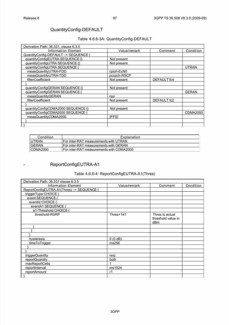
7/15/2019 Lte Sib Info
http://slidepdf.com/reader/full/lte-sib-info 97/187
3GPP
3GPP TS 36.508 V8.3.0 (2009-09)97Release 8
QuantityConfig-DEFAULT
Table 4.6.6-3A: QuantityConfig-DEFAULT
Derivation Path: 36.331, clause 6.3.5Information Element Value/remark Comment Condit ion
QuantityConfig-DEFAULT ::= SEQUENCE {quantityConfigEUTRA SEQUENCE {} Not present
quantityConfigUTRA SEQUENCE {} Not present
quantityConfigUTRA SEQUENCE { UTRAN
measQuantityUTRA-FDD cpich-EcN0
measQuantityUTRA-TDD pccpch-RSCP
filterCoefficient Not present DEFAULT fc4
}
quantityConfigGERAN SEQUENCE {} Not present
quantityConfigGERAN SEQUENCE { GERAN
measQuantityGERAN rssifilterCoefficient Not present DEFAULT fc2
}
quantityConfigCDMA2000 SEQUENCE {} Not present
quantityConfigCDMA2000 SEQUENCE { CDMA2000measQuantityCDMA2000 [FFS]
}
}
Condition Explanation
UTRAN For inter-RAT measurements with UTRAN
GERAN For inter-RAT measurements with GERAN
CDMA2000 For inter-RAT measurements with CDMA2000
- ReportConfigEUTRA-A1
Table 4.6.6-4: ReportConfigEUTRA-A1(Thres)
Derivation Path: 36.331 clause 6.3.5
Information Element Value/remark Comment Condit ion
ReportConfigEUTRA-A1(Thres) ::= SEQUENCE {
triggerType CHOICE {
event SEQUENCE {
eventId CHOICE {
eventA1 SEQUENCE {
a1-Threshold CHOICE {
threshold-RSRP Thres+141 Thres is actualthreshold value indBm
}}
}
hysteresis 0 (0 dB)
timeToTrigger ms256
}
}
triggerQuantity rsrp
reportQuantity both
maxReportCells 1
reportInterval ms1024
reportAmount r1
}
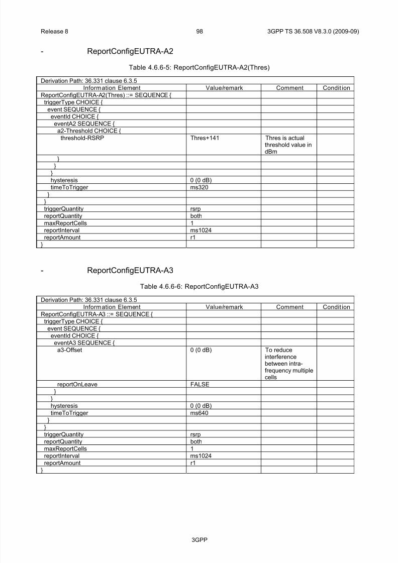
7/15/2019 Lte Sib Info
http://slidepdf.com/reader/full/lte-sib-info 98/187
3GPP
3GPP TS 36.508 V8.3.0 (2009-09)98Release 8
- ReportConfigEUTRA-A2
Table 4.6.6-5: ReportConfigEUTRA-A2(Thres)
Derivation Path: 36.331 clause 6.3.5Information Element Value/remark Comment Condit ion
ReportConfigEUTRA-A2(Thres) ::= SEQUENCE {triggerType CHOICE {
event SEQUENCE {
eventId CHOICE {
eventA2 SEQUENCE {
a2-Threshold CHOICE {
threshold-RSRP Thres+141 Thres is actualthreshold value indBm
}
}
}
hysteresis 0 (0 dB)
timeToTrigger ms320
}}
triggerQuantity rsrp
reportQuantity both
maxReportCells 1
reportInterval ms1024
reportAmount r1
}
- ReportConfigEUTRA-A3
Table 4.6.6-6: ReportConfigEUTRA-A3
Derivation Path: 36.331 clause 6.3.5
Information Element Value/remark Comment Condit ion
ReportConfigEUTRA-A3 ::= SEQUENCE {
triggerType CHOICE {
event SEQUENCE {
eventId CHOICE {
eventA3 SEQUENCE {
a3-Offset 0 (0 dB) To reduceinterferencebetween intra-frequency multiplecells
reportOnLeave FALSE
}}hysteresis 0 (0 dB)
timeToTrigger ms640
}
}
triggerQuantity rsrp
reportQuantity both
maxReportCells 1
reportInterval ms1024
reportAmount r1
}
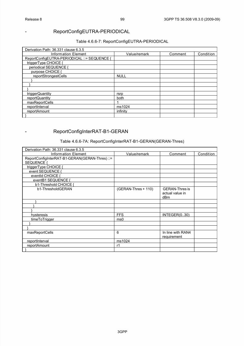
7/15/2019 Lte Sib Info
http://slidepdf.com/reader/full/lte-sib-info 99/187
3GPP
3GPP TS 36.508 V8.3.0 (2009-09)99Release 8
- ReportConfigEUTRA-PERIODICAL
Table 4.6.6-7: ReportConfigEUTRA-PERIODICAL
Derivation Path: 36.331 clause 6.3.5Information Element Value/remark Comment Condit ion
ReportConfigEUTRA-PERIODICAL ::= SEQUENCE {triggerType CHOICE {
periodical SEQUENCE {
purpose CHOICE {
reportStrongestCells NULL
}
}
}
triggerQuantity rsrp
reportQuantity both
maxReportCells 1reportInterval ms1024
reportAmount infinity
}
- ReportConfigInterRAT-B1-GERAN
Table 4.6.6-7A: ReportConfigInterRAT-B1-GERAN(GERAN-Thres)
Derivation Path: 36.331 clause 6.3.5
Information Element Value/remark Comment Condit ion
ReportConfigInterRAT-B1-GERAN(GERAN-Thres) ::=SEQUENCE {triggerType CHOICE {
event SEQUENCE {
eventId CHOICE {
eventB1 SEQUENCE {b1-Threshold CHOICE {
b1-ThresholdGERAN (GERAN-Thres + 110) GERAN-Thres isactual value indBm
}
}
}
hysteresis FFS INTEGER(0..30)
timeToTrigger ms0
}
}
maxReportCells 6 In line with RAN4requirement
reportInterval ms1024reportAmount r1
}
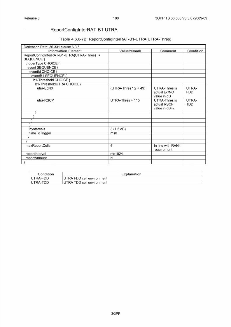
7/15/2019 Lte Sib Info
http://slidepdf.com/reader/full/lte-sib-info 100/187
3GPP
3GPP TS 36.508 V8.3.0 (2009-09)100Release 8
- ReportConfigInterRAT-B1-UTRA
Table 4.6.6-7B: ReportConfigInterRAT-B1-UTRA(UTRA-Thres)
Derivation Path: 36.331 clause 6.3.5Information Element Value/remark Comment Condit ion
ReportConfigInterRAT-B1-UTRA(UTRA-Thres) ::=SEQUENCE {
triggerType CHOICE {
event SEQUENCE {
eventId CHOICE {
eventB1 SEQUENCE {
b1-Threshold CHOICE {
b1-ThresholdUTRA CHOICE {
utra-EcN0 (UTRA-Thres * 2 + 49) UTRA-Thres isactual Ec/NOvalue in dB
UTRA-FDD
utra-RSCP UTRA-Thres + 115 UTRA-Thres isactual RSCPvalue in dBm
UTRA-TDD
}}
}
}
hysteresis 3 (1.5 dB)
timeToTrigger ms0
}
}
maxReportCells 6 In line with RAN4requirement
reportInterval ms1024
reportAmount r1
}
Condition Explanation
UTRA-FDD UTRA FDD cell environment
UTRA-TDD UTRA TDD cell environment
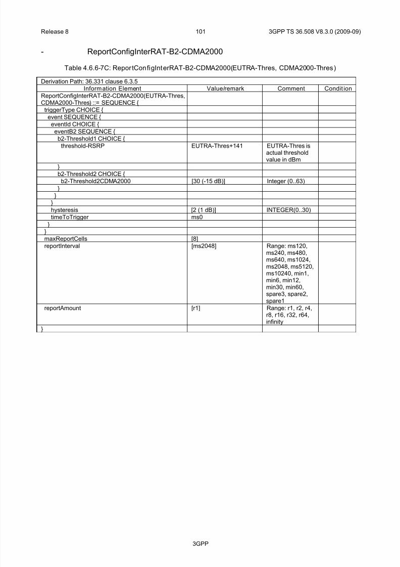
7/15/2019 Lte Sib Info
http://slidepdf.com/reader/full/lte-sib-info 101/187
3GPP
3GPP TS 36.508 V8.3.0 (2009-09)101Release 8
- ReportConfigInterRAT-B2-CDMA2000
Table 4.6.6-7C: Repor tConfigInterRAT-B2-CDMA2000(EUTRA-Thres, CDMA2000-Thres)
Derivation Path: 36.331 clause 6.3.5Information Element Value/remark Comment Condit ion
ReportConfigInterRAT-B2-CDMA2000(EUTRA-Thres,CDMA2000-Thres) ::= SEQUENCE {
triggerType CHOICE {
event SEQUENCE {
eventId CHOICE {
eventB2 SEQUENCE {
b2-Threshold1 CHOICE {
threshold-RSRP EUTRA-Thres+141 EUTRA-Thres isactual thresholdvalue in dBm
}
b2-Threshold2 CHOICE {
b2-Threshold2CDMA2000 [30 (-15 dB)] Integer (0..63)
}
}}
hysteresis [2 (1 dB)] INTEGER(0..30)
timeToTrigger ms0
}
}
maxReportCells [8]
reportInterval [ms2048] Range: ms120,ms240, ms480,ms640, ms1024,ms2048, ms5120,ms10240, min1,min6, min12,min30, min60,
spare3, spare2,spare1
reportAmount [r1] Range: r1, r2, r4,r8, r16, r32, r64,infinity
}
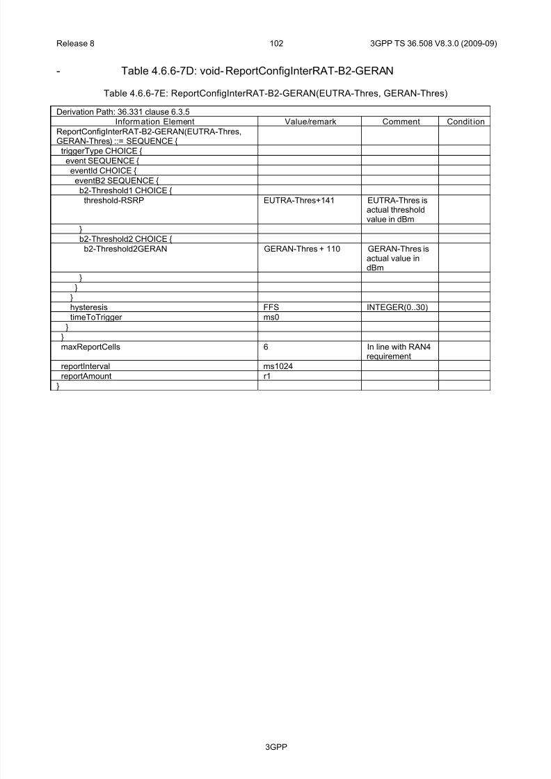
7/15/2019 Lte Sib Info
http://slidepdf.com/reader/full/lte-sib-info 102/187
3GPP
3GPP TS 36.508 V8.3.0 (2009-09)102Release 8
- Table 4.6.6-7D: void- ReportConfigInterRAT-B2-GERAN
Table 4.6.6-7E: ReportConfigInterRAT-B2-GERAN(EUTRA-Thres, GERAN-Thres)
Derivation Path: 36.331 clause 6.3.5Information Element Value/remark Comment Condit ion
ReportConfigInterRAT-B2-GERAN(EUTRA-Thres,GERAN-Thres) ::= SEQUENCE {
triggerType CHOICE {
event SEQUENCE {
eventId CHOICE {
eventB2 SEQUENCE {
b2-Threshold1 CHOICE {
threshold-RSRP EUTRA-Thres+141 EUTRA-Thres isactual thresholdvalue in dBm
}
b2-Threshold2 CHOICE {
b2-Threshold2GERAN GERAN-Thres + 110 GERAN-Thres isactual value in
dBm}
}
}
hysteresis FFS INTEGER(0..30)
timeToTrigger ms0
}
}
maxReportCells 6 In line with RAN4requirement
reportInterval ms1024
reportAmount r1
}
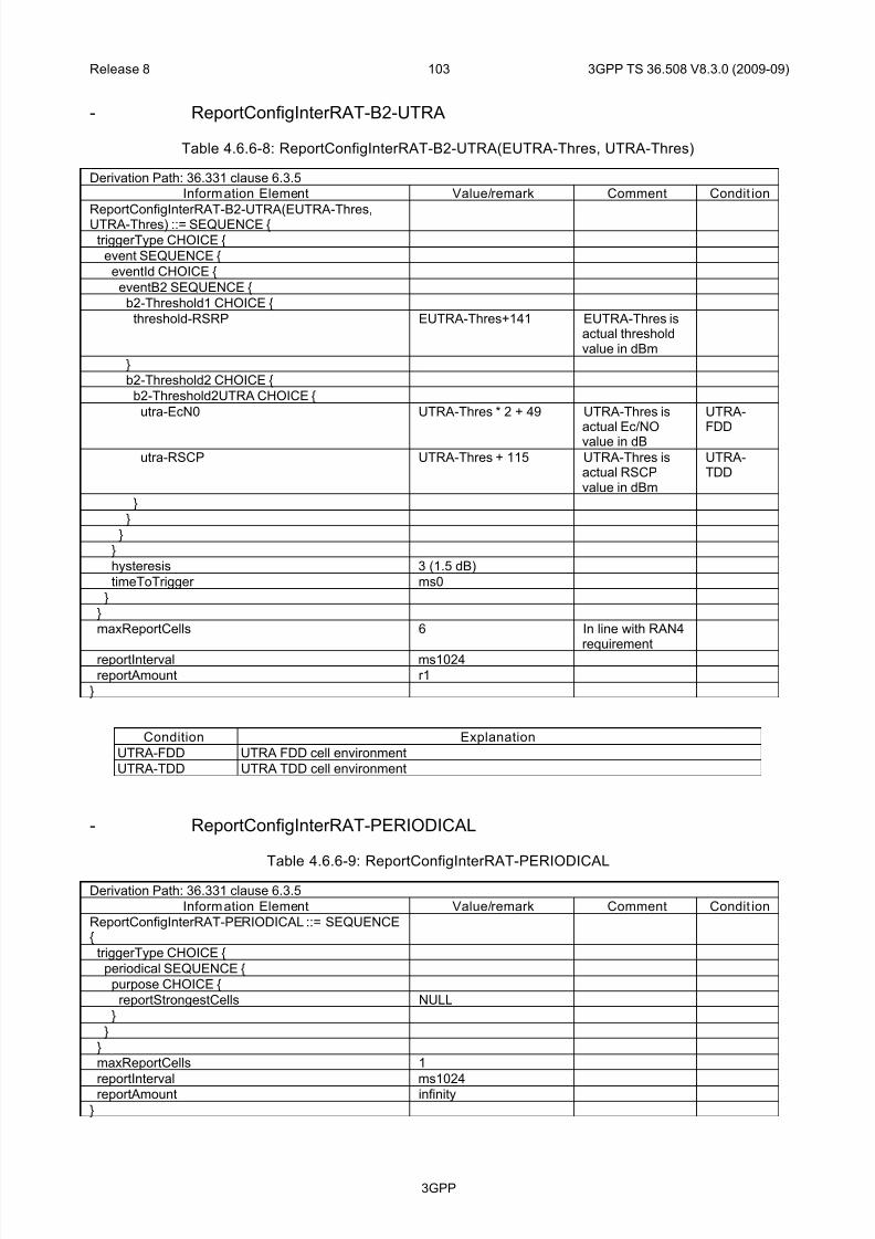
7/15/2019 Lte Sib Info
http://slidepdf.com/reader/full/lte-sib-info 103/187
3GPP
3GPP TS 36.508 V8.3.0 (2009-09)103Release 8
- ReportConfigInterRAT-B2-UTRA
Table 4.6.6-8: ReportConfigInterRAT-B2-UTRA(EUTRA-Thres, UTRA-Thres)
Derivation Path: 36.331 clause 6.3.5Information Element Value/remark Comment Condit ion
ReportConfigInterRAT-B2-UTRA(EUTRA-Thres,UTRA-Thres) ::= SEQUENCE {
triggerType CHOICE {
event SEQUENCE {
eventId CHOICE {
eventB2 SEQUENCE {
b2-Threshold1 CHOICE {
threshold-RSRP EUTRA-Thres+141 EUTRA-Thres isactual thresholdvalue in dBm
}
b2-Threshold2 CHOICE {
b2-Threshold2UTRA CHOICE {
utra-EcN0 UTRA-Thres * 2 + 49 UTRA-Thres is
actual Ec/NOvalue in dB
UTRA-
FDD
utra-RSCP UTRA-Thres + 115 UTRA-Thres isactual RSCPvalue in dBm
UTRA-TDD
}
}
}
}
hysteresis 3 (1.5 dB)
timeToTrigger ms0
}
}
maxReportCells 6 In line with RAN4
requirementreportInterval ms1024
reportAmount r1
}
Condition Explanation
UTRA-FDD UTRA FDD cell environment
UTRA-TDD UTRA TDD cell environment
- ReportConfigInterRAT-PERIODICAL
Table 4.6.6-9: ReportConfigInterRAT-PERIODICAL
Derivation Path: 36.331 clause 6.3.5
Information Element Value/remark Comment Condit ion
ReportConfigInterRAT-PERIODICAL ::= SEQUENCE{
triggerType CHOICE {
periodical SEQUENCE {
purpose CHOICE {
reportStrongestCells NULL
}
}
}
maxReportCells 1
reportInterval ms1024reportAmount infinity
}
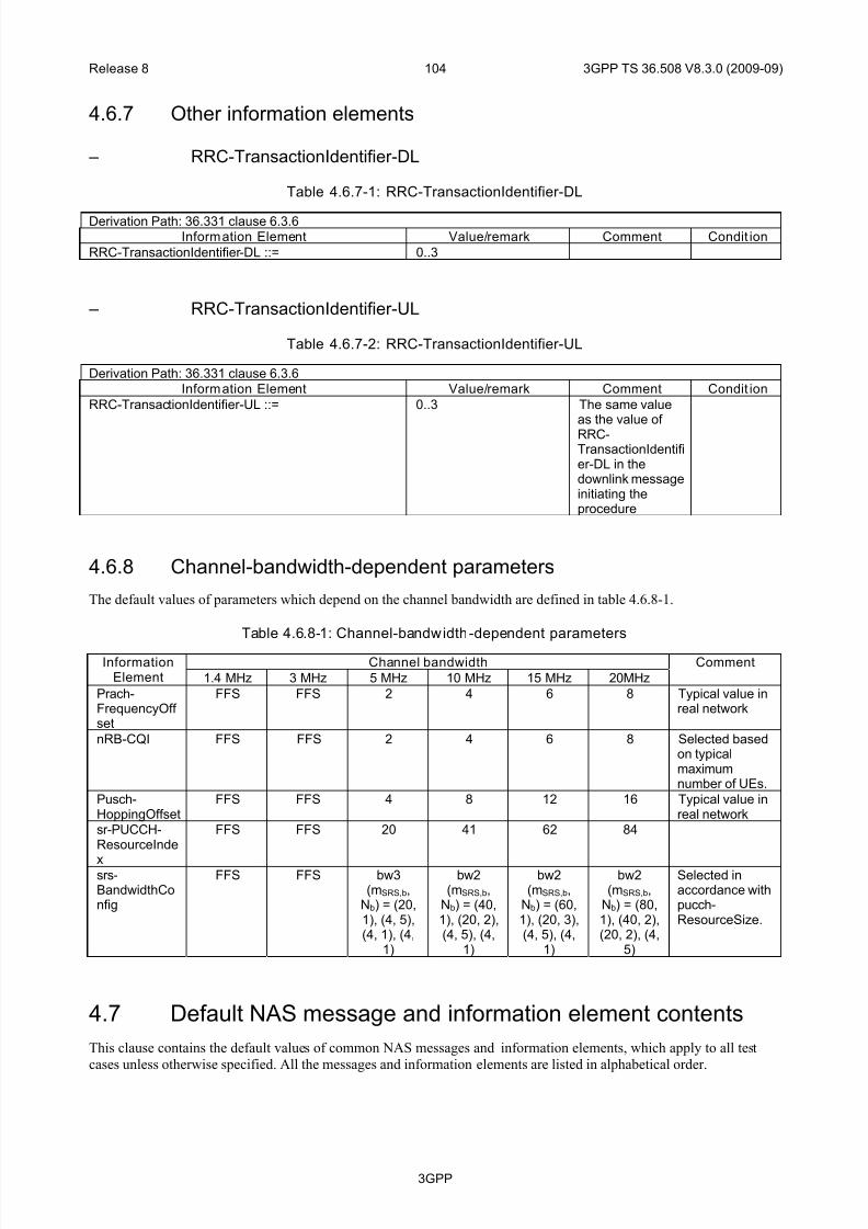
7/15/2019 Lte Sib Info
http://slidepdf.com/reader/full/lte-sib-info 104/187
3GPP
3GPP TS 36.508 V8.3.0 (2009-09)104Release 8
4.6.7 Other information elements
– RRC-TransactionIdentifier-DL
Table 4.6.7-1: RRC-TransactionIdentifier-DL
Derivation Path: 36.331 clause 6.3.6Information Element Value/remark Comment Condit ion
RRC-TransactionIdentifier-DL ::= 0..3
– RRC-TransactionIdentifier-UL
Table 4.6.7-2: RRC-TransactionIdentifier-UL
Derivation Path: 36.331 clause 6.3.6Information Element Value/remark Comment Condit ion
RRC-TransactionIdentifier-UL ::= 0..3 The same valueas the value of RRC-TransactionIdentifier-DL in thedownlink messageinitiating theprocedure
4.6.8 Channel-bandwidth-dependent parameters
The default values of parameters which depend on the channel bandwidth are defined in table 4.6.8-1.
Table 4.6.8-1: Channel-bandwidth-dependent parametersChannel bandwidthInformation
Element 1.4 MHz 3 MHz 5 MHz 10 MHz 15 MHz 20MHz
Comment
Prach-FrequencyOff set
FFS FFS 2 4 6 8 Typical value inreal network
nRB-CQI FFS FFS 2 4 6 8 Selected basedon typicalmaximumnumber of UEs.
Pusch-HoppingOffset
FFS FFS 4 8 12 16 Typical value inreal network
sr-PUCCH-ResourceIndex
FFS FFS 20 41 62 84
srs-BandwidthConfig
FFS FFS bw3(mSRS,b,
Nb) = (20,1), (4, 5),(4, 1), (4,
1)
bw2(mSRS,b,
Nb) = (40,1), (20, 2),(4, 5), (4,
1)
bw2(mSRS,b,
Nb) = (60,1), (20, 3),(4, 5), (4,
1)
bw2(mSRS,b,
Nb) = (80,1), (40, 2),(20, 2), (4,
5)
Selected inaccordance withpucch-ResourceSize.
4.7 Default NAS message and information element contents
This clause contains the default values of common NAS messages and information elements, which apply to all test
cases unless otherwise specified. All the messages and information elements are listed in alphabetical order.

7/15/2019 Lte Sib Info
http://slidepdf.com/reader/full/lte-sib-info 105/187
3GPP
3GPP TS 36.508 V8.3.0 (2009-09)105Release 8
4.7.1 Security protected NAS messages
In subclauses 4.7.2 and 4.7.3 in this document, all the NAS messages are described in the plain NAS message format.
When a NAS message is security protected, the message shall be contained by SECURITY PROTECTED NASMESSAGE unless contained by another NAS message.
The default contents of SECURITY PROTECTED NAS MESSAGE message are defined in table 4.7.1-1.
Table 4.7.1-1: SECURITY PROTECTED NAS MESSAGE
Derivation Path: 24.301 clause 8.2.23
Information Element Value/remark Comment Condit ion
Protocol discriminator EMM
Security header type '0001'B Integrity protected UNCIPHERED
'0010'B Integrity protectedand ciphered
CIPHERED
'0011'B Integrity protectedwith new EPS
security context
UNCIPHERED-NEW
'0100'B Integrity protectedand ciphered withnew EPS securitycontext
CIPHERED-NEW
Message authentication code The calculated value of MAC-I for this message.
The value of MAC-I iscalculated by SSusing Sequencenumber sent byUE.
SENT-BY-SS
The same value as theXMAC-I value calculatedby SS.
SENT-BY-UE
Sequence number The internal counter of the SS
SENT-BY-SS
Any allowed value SENT-BY-UE
NAS message Set according to specificmessage content
Condition Explanation
UNCIPHERED This condition applies to unciphered NAS message exchange
CIPHERED This condition applies to ciphered NAS message exchange
UNCIPHERED-NEW This condition applies to unciphered NAS message exchange withnew EPS security context
CIPHERED-NEW This condition applies to ciphered NAS message exchange with newEPS security context
SENT-BY-SS Use for the message sent from SS to UE
SENT-BY-UE Use for the message sent from UE to SS
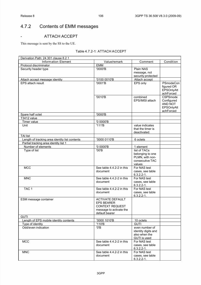
7/15/2019 Lte Sib Info
http://slidepdf.com/reader/full/lte-sib-info 106/187
3GPP
3GPP TS 36.508 V8.3.0 (2009-09)106Release 8
4.7.2 Contents of EMM messages
- ATTACH ACCEPT
This message is sent by the SS to the UE.
Table 4.7.2-1: ATTACH ACCEPT
Derivation Path: 24.301 clause 8.2.1Information Element Value/remark Comment Condit ion
Protocol discriminator EMM
Security header type '0000'B Plain NASmessage, notsecurity protected
Attach accept message identity '0100 0010'B Attach accept
EPS attach result '0001'B EPS only PSmodeConfigured OREPSOnlyAttachForced
'0010'B combinedEPS/IMSI attach
CSPSmodeConfigured AND NOTEPSOnlyAttachForced
Spare half octet '0000'B
T3412 value
Timer value '0 0000'B
Unit '111'B value indicatesthat the timer isdeactivated.
TAI list
Length of tracking area identity list contents '0000 0110'B 6 octets
Partial tracking area identity list 1
Number of elements '0 0000'B 1 elementType of list '00'B list of TACs
belonging to onePLMN, with non-consecutive TACvalues
MCC See table 4.4.2-2 in thisdocument
For NAS testcases, see table6.3.2.2-1.
MNC See table 4.4.2-2 in thisdocument
For NAS testcases, see table6.3.2.2-1.
TAC 1 See table 4.4.2-2 in thisdocument
For NAS testcases, see table6.3.2.2-1.
ESM message container ACTIVATE DEFAULTEPS BEARERCONTEXT REQUESTmessage to activate thedefault bearer
GUTI
Length of EPS mobile identity contents '0000 1010'B 10 octets
Type of identity '110'B GUTI
Odd/even indication '0'B even number of identity digits andalso when theGUTI is used
MCC See table 4.4.2-2 in thisdocument
For NAS testcases, see table
6.3.2.2-1.MNC See table 4.4.2-2 in this
documentFor NAS testcases, see table6.3.2.2-1.
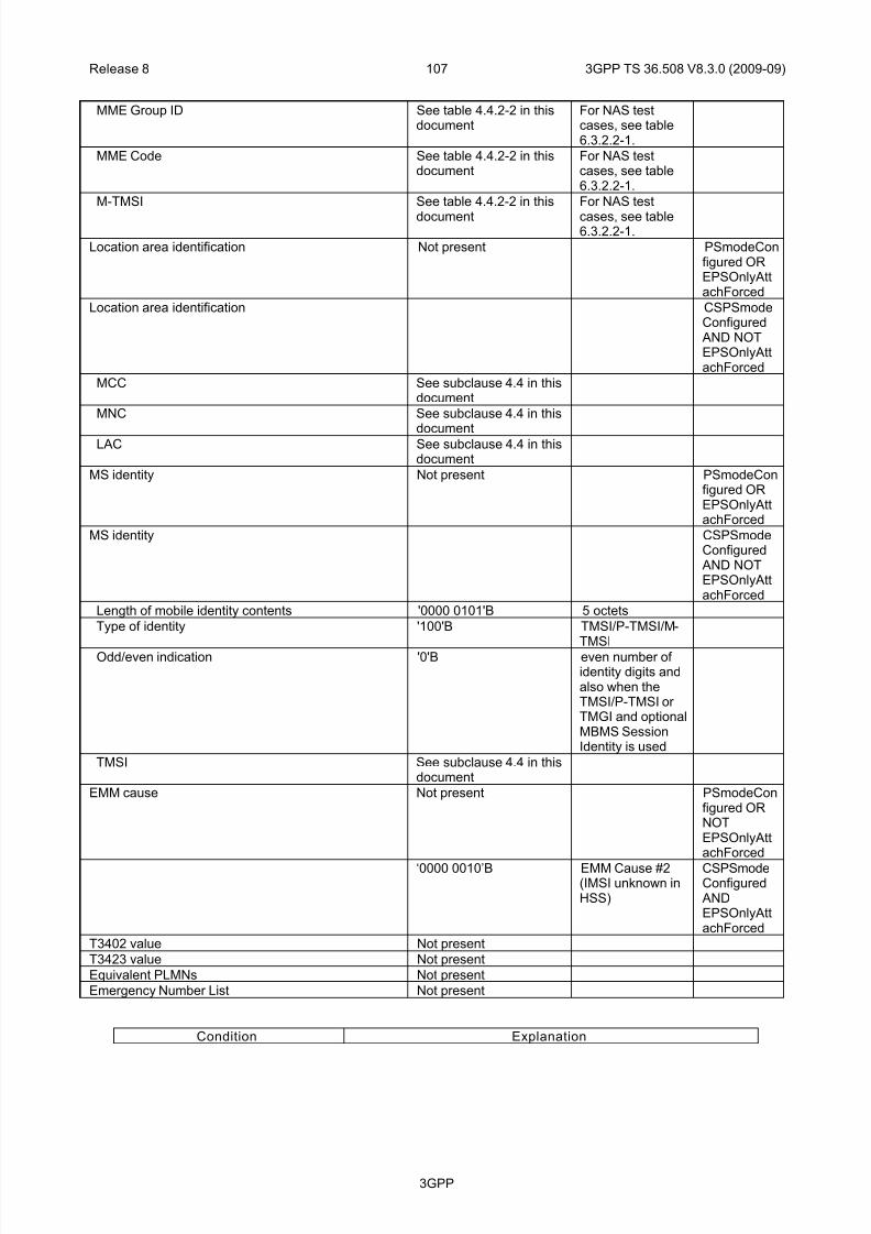
7/15/2019 Lte Sib Info
http://slidepdf.com/reader/full/lte-sib-info 107/187
3GPP
3GPP TS 36.508 V8.3.0 (2009-09)107Release 8
MME Group ID See table 4.4.2-2 in thisdocument
For NAS testcases, see table6.3.2.2-1.
MME Code See table 4.4.2-2 in thisdocument
For NAS testcases, see table6.3.2.2-1.
M-TMSI See table 4.4.2-2 in this
document
For NAS test
cases, see table6.3.2.2-1.
Location area identification Not present PSmodeConfigured OREPSOnlyAttachForced
Location area identification CSPSmodeConfigured AND NOTEPSOnlyAttachForced
MCC See subclause 4.4 in thisdocument
MNC See subclause 4.4 in this
documentLAC See subclause 4.4 in this
document
MS identity Not present PSmodeConfigured OREPSOnlyAttachForced
MS identity CSPSmodeConfigured AND NOTEPSOnlyAttachForced
Length of mobile identity contents '0000 0101'B 5 octets
Type of identity '100'B TMSI/P-TMSI/M-
TMSIOdd/even indication '0'B even number of
identity digits andalso when theTMSI/P-TMSI or TMGI and optionalMBMS SessionIdentity is used
TMSI See subclause 4.4 in thisdocument
EMM cause Not present PSmodeConfigured ORNOTEPSOnlyAtt
achForced‘0000 0010’B EMM Cause #2(IMSI unknown inHSS)
CSPSmodeConfigured ANDEPSOnlyAttachForced
T3402 value Not present
T3423 value Not present
Equivalent PLMNs Not present
Emergency Number List Not present
Condition Explanation
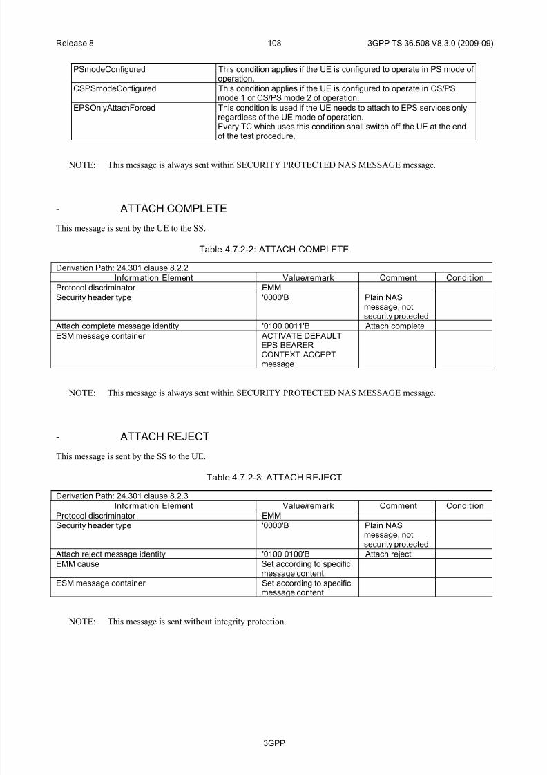
7/15/2019 Lte Sib Info
http://slidepdf.com/reader/full/lte-sib-info 108/187
3GPP
3GPP TS 36.508 V8.3.0 (2009-09)108Release 8
PSmodeConfigured This condition applies if the UE is configured to operate in PS mode of operation.
CSPSmodeConfigured This condition applies if the UE is configured to operate in CS/PSmode 1 or CS/PS mode 2 of operation.
EPSOnlyAttachForced This condition is used if the UE needs to attach to EPS services onlyregardless of the UE mode of operation.Every TC which uses this condition shall switch off the UE at the end
of the test procedure.
NOTE: This message is always sent within SECURITY PROTECTED NAS MESSAGE message.
- ATTACH COMPLETE
This message is sent by the UE to the SS.
Table 4.7.2-2: ATTACH COMPLETE
Derivation Path: 24.301 clause 8.2.2Information Element Value/remark Comment Condit ion
Protocol discriminator EMM
Security header type '0000'B Plain NASmessage, notsecurity protected
Attach complete message identity '0100 0011'B Attach complete
ESM message container ACTIVATE DEFAULTEPS BEARERCONTEXT ACCEPTmessage
NOTE: This message is always sent within SECURITY PROTECTED NAS MESSAGE message.
- ATTACH REJECT
This message is sent by the SS to the UE.
Table 4.7.2-3: ATTACH REJECT
Derivation Path: 24.301 clause 8.2.3
Information Element Value/remark Comment Condit ion
Protocol discriminator EMM
Security header type '0000'B Plain NAS
message, notsecurity protected
Attach reject message identity '0100 0100'B Attach reject
EMM cause Set according to specificmessage content.
ESM message container Set according to specificmessage content.
NOTE: This message is sent without integrity protection.

7/15/2019 Lte Sib Info
http://slidepdf.com/reader/full/lte-sib-info 109/187
3GPP
3GPP TS 36.508 V8.3.0 (2009-09)109Release 8
- ATTACH REQUEST
This message is sent by the UE to the SS.
Table 4.7.2-4: ATTACH REQUEST
Derivation Path: 24.301 clause 8.2.4
Information Element Value/remark Comment Condit ion
Protocol discriminator EMM
Security header type '0000'B Plain NASmessage, notsecurity protected
Attach request message identity '0100 0001'B Attach request
EPS attach type '0001'B EPS attach PSmodeConfigured
'0010'B combinedEPS/IMSI attach
CSPSmodeConfigured
NAS key set identifier Any allowed value
Old GUTI or IMSI Any allowed value
UE network capability Any allowed value
ESM message container PDN CONNECTIVITYREQUEST message torequest PDN connectivityto the default PDN
Old P-TMSI signature Not present or anyallowed value
Additional GUTI Not present or anyallowed value
Last visited registered TAI Not present or anyallowed value
DRX parameter Not present or anyallowed value
MS network capability Not present or anyallowed value
Old location area identification Not present or anyallowed value
TMSI status Not present or anyallowed value
Mobile station classmark 2 Not present or anyallowed value
Mobile station classmark 3 Not present or anyallowed value
Supported Codecs Not present or anyallowed value
Condition Explanation
PSmodeConfigured See the definition below table 4.7.2-1.
CSPSmodeConfigured See the definition below table 4.7.2-1.
NOTE: This message is sent without integrity protection before NAS security mode control procedure has beensuccessfully completed and sent within SECURITY PROTECTED NAS MESSAGE message after NASsecurity mode control procedure has been successfully completed.

7/15/2019 Lte Sib Info
http://slidepdf.com/reader/full/lte-sib-info 110/187
3GPP
3GPP TS 36.508 V8.3.0 (2009-09)110Release 8
- AUTHENTICATION FAILURE
This message is sent by the UE to the SS.
Table 4.7.2-5: AUTHENTICATION FAILURE
Derivation Path: 24.301 clause 8.2.5
Information Element Value/remark Comment Condit ion
Protocol discriminator EMM
Security header type '0000'B Plain NASmessage, notsecurity protected
Authentication failure message type '0101 1100'B Authenticationfailure
EMM cause '0001 0100'B Mac failure
Authentication failure parameter Not present See TS 24.301[28] subclause8.2.5.2
NOTE: This message is sent without integrity protection before NAS security mode control procedure has beensuccessfully completed and sent within SECURITY PROTECTED NAS MESSAGE message after NASsecurity mode control procedure has been successfully completed.
- AUTHENTICATION REJECT
This message is sent by the SS to the UE.
Table 4.7.2-6: AUTHENTICATION REJECT
Derivation Path: 24.301 clause 8.2.6
Information Element Value/remark Comment Condit ion
Protocol discriminator EMM
Security header type '0000'B Plain NASmessage, notsecurity protected
Authentication reject message type '0101 0100'B Authenticationreject
NOTE: This message is sent without integrity protection.
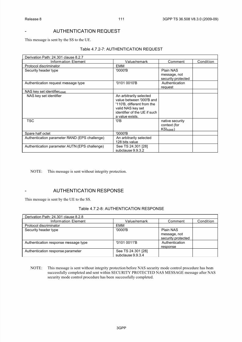
7/15/2019 Lte Sib Info
http://slidepdf.com/reader/full/lte-sib-info 111/187
3GPP
3GPP TS 36.508 V8.3.0 (2009-09)111Release 8
- AUTHENTICATION REQUEST
This message is sent by the SS to the UE.
Table 4.7.2-7: AUTHENTICATION REQUEST
Derivation Path: 24.301 clause 8.2.7
Information Element Value/remark Comment Condit ion
Protocol discriminator EMM
Security header type '0000'B Plain NASmessage, notsecurity protected
Authentication request message type '0101 0010'B Authenticationrequest
NAS key set identifier ASME
NAS key set identifier An arbitrarily selectedvalue between '000'B and'110'B, different from thevalid NAS key setidentifier of the UE if sucha value exists.
TSC '0'B native securitycontext (for KSI ASME)
Spare half octet '0000'B
Authentication parameter RAND (EPS challenge) An arbitrarily selected128 bits value
Authentication parameter AUTN (EPS challenge) See TS 24.301 [28]subclause 9.9.3.2
NOTE: This message is sent without integrity protection.
- AUTHENTICATION RESPONSE
This message is sent by the UE to the SS.
Table 4.7.2-8: AUTHENTICATION RESPONSE
Derivation Path: 24.301 clause 8.2.8
Information Element Value/remark Comment Condit ion
Protocol discriminator EMM
Security header type '0000'B Plain NASmessage, not
security protected Authentication response message type '0101 0011'B Authentication
response
Authentication response parameter See TS 24.301 [28]subclause 9.9.3.4
NOTE: This message is sent without integrity protection before NAS security mode control procedure has beensuccessfully completed and sent within SECURITY PROTECTED NAS MESSAGE message after NASsecurity mode control procedure has been successfully completed.
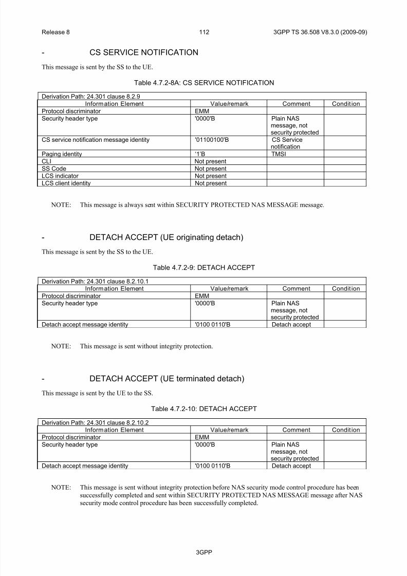
7/15/2019 Lte Sib Info
http://slidepdf.com/reader/full/lte-sib-info 112/187
3GPP
3GPP TS 36.508 V8.3.0 (2009-09)112Release 8
- CS SERVICE NOTIFICATION
This message is sent by the SS to the UE.
Table 4.7.2-8A: CS SERVICE NOTIFICATION
Derivation Path: 24.301 clause 8.2.9
Information Element Value/remark Comment Condit ion
Protocol discriminator EMM
Security header type '0000'B Plain NASmessage, notsecurity protected
CS service notification message identity '01100100'B CS Servicenotification
Paging identity ‘1’B TMSI
CLI Not present
SS Code Not present
LCS indicator Not present
LCS client identity Not present
NOTE: This message is always sent within SECURITY PROTECTED NAS MESSAGE message.
- DETACH ACCEPT (UE originating detach)
This message is sent by the SS to the UE.
Table 4.7.2-9: DETACH ACCEPT
Derivation Path: 24.301 clause 8.2.10.1Information Element Value/remark Comment Condit ion
Protocol discriminator EMM
Security header type '0000'B Plain NASmessage, notsecurity protected
Detach accept message identity '0100 0110'B Detach accept
NOTE: This message is sent without integrity protection.
- DETACH ACCEPT (UE terminated detach)
This message is sent by the UE to the SS.
Table 4.7.2-10: DETACH ACCEPT
Derivation Path: 24.301 clause 8.2.10.2Information Element Value/remark Comment Condit ion
Protocol discriminator EMM
Security header type '0000'B Plain NASmessage, notsecurity protected
Detach accept message identity '0100 0110'B Detach accept
NOTE: This message is sent without integrity protection before NAS security mode control procedure has beensuccessfully completed and sent within SECURITY PROTECTED NAS MESSAGE message after NASsecurity mode control procedure has been successfully completed.

7/15/2019 Lte Sib Info
http://slidepdf.com/reader/full/lte-sib-info 113/187
3GPP
3GPP TS 36.508 V8.3.0 (2009-09)113Release 8
- DETACH REQUEST (UE originating detach)
This message is sent by the UE to the SS.
Table 4.7.2-11: DETACH REQUEST
Derivation Path: 24.301 clause 8.2.11.1
Information Element Value/remark Comment Condit ion
Protocol discriminator EMM
Security header type '0000'B Plain NASmessage, notsecurity protected
Detach request message identity '0100 0101'B Detach request
Detach type
Type of detach '001'B EPS detach EPSOnlyAttach
‘011’B combinedEPS/IMSI detach
CombinedAttach
Switch off '1'B switch off
NAS key set identifier
NAS key set identifier The valid NAS key setidentifier.
TSC '0'B native securitycontext (for KSI ASME)
GUTI or IMSI If the UE has a validGUTI, set to the GUTI,otherwise set to the IMSIof the UE.
Condition Explanation
EPSOnlyAttach See the definition below table 4.7.2-24.CombinedAttach See the definition below table 4.7.2-24.
NOTE: This message is sent without integrity protection before NAS security mode control procedure has beensuccessfully completed and sent within SECURITY PROTECTED NAS MESSAGE message after NASsecurity mode control procedure has been successfully completed.
- DETACH REQUEST (UE terminated detach)
This message is sent by the SS to the UE.
Table 4.7.2-12: DETACH REQUEST
Derivation Path: 24.301 clause 8.2.11.2
Information Element Value/remark Comment Condit ion
Protocol discriminator EMM
Security header type '0000'B Plain NASmessage, notsecurity protected
Detach request message identity '0100 0101'B Detach request
Detach type Set according to specificmessage content.
Spare half octet '0000'BEMM cause Set according to specific
message content.
NOTE: This message is always sent within SECURITY PROTECTED NAS MESSAGE message.
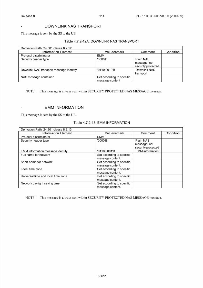
7/15/2019 Lte Sib Info
http://slidepdf.com/reader/full/lte-sib-info 114/187
3GPP
3GPP TS 36.508 V8.3.0 (2009-09)114Release 8
- DOWNLINK NAS TRANSPORT
This message is sent by the SS to the UE.
Table 4.7.2-12A: DOWNLINK NAS TRANSPORT
Derivation Path: 24.301 clause 8.2.12
Information Element Value/remark Comment Condit ion
Protocol discriminator EMM
Security header type '0000'B Plain NASmessage, notsecurity protected
Downlink NAS transport message identity '0110 0010'B Downlink NAStransport
NAS message container Set according to specificmessage content
NOTE: This message is always sent within SECURITY PROTECTED NAS MESSAGE message.
- EMM INFORMATION
This message is sent by the SS to the UE.
Table 4.7.2-13: EMM INFORMATION
Derivation Path: 24.301 clause 8.2.13
Information Element Value/remark Comment Condit ion
Protocol discriminator EMM
Security header type '0000'B Plain NASmessage, notsecurity protected
EMM information message identity '0110 0001'B EMM informationFull name for network Set according to specific
message content.
Short name for network Set according to specificmessage content.
Local time zone Set according to specificmessage content.
Universal time and local time zone Set according to specificmessage content.
Network daylight saving time Set according to specificmessage content.
NOTE: This message is always sent within SECURITY PROTECTED NAS MESSAGE message.
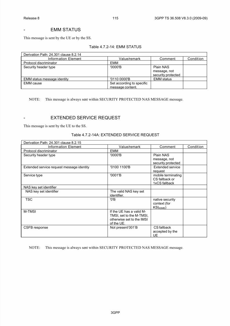
7/15/2019 Lte Sib Info
http://slidepdf.com/reader/full/lte-sib-info 115/187
3GPP
3GPP TS 36.508 V8.3.0 (2009-09)115Release 8
- EMM STATUS
This message is sent by the UE or by the SS.
Table 4.7.2-14: EMM STATUS
Derivation Path: 24.301 clause 8.2.14
Information Element Value/remark Comment Condit ion
Protocol discriminator EMM
Security header type '0000'B Plain NASmessage, notsecurity protected
EMM status message identity '0110 0000'B EMM status
EMM cause Set according to specificmessage content.
NOTE: This message is always sent within SECURITY PROTECTED NAS MESSAGE message.
- EXTENDED SERVICE REQUEST
This message is sent by the UE to the SS.
Table 4.7.2-14A: EXTENDED SERVICE REQUEST
Derivation Path: 24.301 clause 8.2.15Information Element Value/remark Comment Condit ion
Protocol discriminator EMM
Security header type '0000'B Plain NASmessage, notsecurity protected
Extended service request message identity '0100 1100'B Extended service
requestService type '0001'B mobile terminating
CS fallback or 1xCS fallback
NAS key set identifier
NAS key set identifier The valid NAS key setidentifier.
TSC '0'B native securitycontext (for KSI ASME)
M-TMSI If the UE has a valid M-TMSI, set to the M-TMSI,otherwise set to the IMSIof the UE.
CSFB response Not present’001’B CS fallbackaccepted by theUE
NOTE: This message is always sent within SECURITY PROTECTED NAS MESSAGE message.
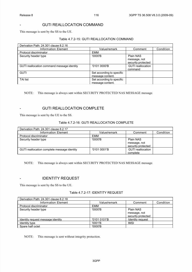
7/15/2019 Lte Sib Info
http://slidepdf.com/reader/full/lte-sib-info 116/187
3GPP
3GPP TS 36.508 V8.3.0 (2009-09)116Release 8
- GUTI REALLOCATION COMMAND
This message is sent by the SS to the UE.
Table 4.7.2-15: GUTI REALLOCATION COMMAND
Derivation Path: 24.301 clause 8.2.16
Information Element Value/remark Comment Condit ion
Protocol discriminator EMM
Security header type '0000'B Plain NASmessage, notsecurity protected
GUTI reallocation command message identity '0101 0000'B GUTI reallocationcommand
GUTI Set according to specificmessage content.
TAI list Set according to specificmessage content.
NOTE: This message is always sent within SECURITY PROTECTED NAS MESSAGE message.
- GUTI REALLOCATION COMPLETE
This message is sent by the UE to the SS.
Table 4.7.2-16: GUTI REALLOCATION COMPLETE
Derivation Path: 24.301 clause 8.2.17Information Element Value/remark Comment Condit ion
Protocol discriminator EMM
Security header type '0000'B Plain NAS
message, notsecurity protected
GUTI reallocation complete message identity '0101 0001'B GUTI reallocationcomplete
NOTE: This message is always sent within SECURITY PROTECTED NAS MESSAGE message.
- IDENTITY REQUEST
This message is sent by the SS to the UE.
Table 4.7.2-17: IDENTITY REQUEST
Derivation Path: 24.301 clause 8.2.18
Information Element Value/remark Comment Condit ion
Protocol discriminator EMM
Security header type '0000'B Plain NASmessage, notsecurity protected
Identity request message identity '0101 0101'B Identity request
Identity type '0001'B IMSI
Spare half octet '0000'B
NOTE: This message is sent without integrity protection.
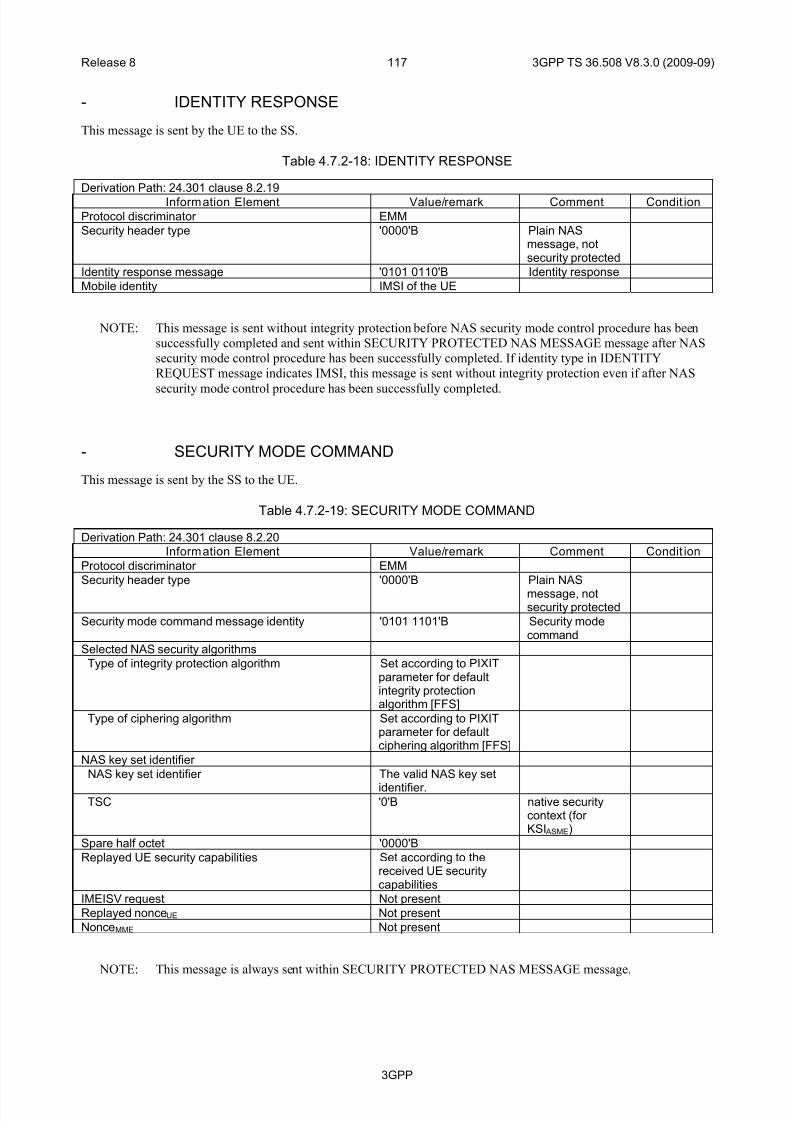
7/15/2019 Lte Sib Info
http://slidepdf.com/reader/full/lte-sib-info 117/187
3GPP
3GPP TS 36.508 V8.3.0 (2009-09)117Release 8
- IDENTITY RESPONSE
This message is sent by the UE to the SS.
Table 4.7.2-18: IDENTITY RESPONSE
Derivation Path: 24.301 clause 8.2.19
Information Element Value/remark Comment Condit ion
Protocol discriminator EMM
Security header type '0000'B Plain NASmessage, notsecurity protected
Identity response message '0101 0110'B Identity response
Mobile identity IMSI of the UE
NOTE: This message is sent without integrity protection before NAS security mode control procedure has beensuccessfully completed and sent within SECURITY PROTECTED NAS MESSAGE message after NASsecurity mode control procedure has been successfully completed. If identity type in IDENTITYREQUEST message indicates IMSI, this message is sent without integrity protection even if after NAS
security mode control procedure has been successfully completed.
- SECURITY MODE COMMAND
This message is sent by the SS to the UE.
Table 4.7.2-19: SECURITY MODE COMMAND
Derivation Path: 24.301 clause 8.2.20Information Element Value/remark Comment Condit ion
Protocol discriminator EMM
Security header type '0000'B Plain NASmessage, notsecurity protected
Security mode command message identity '0101 1101'B Security modecommand
Selected NAS security algorithms
Type of integrity protection algorithm Set according to PIXITparameter for defaultintegrity protectionalgorithm [FFS]
Type of ciphering algorithm Set according to PIXITparameter for defaultciphering algorithm [FFS]
NAS key set identifier
NAS key set identifier The valid NAS key setidentifier.
TSC '0'B native securitycontext (for KSI ASME)
Spare half octet '0000'B
Replayed UE security capabilities Set according to thereceived UE securitycapabilities
IMEISV request Not present
Replayed nonceUE Not present
NonceMME Not present
NOTE: This message is always sent within SECURITY PROTECTED NAS MESSAGE message.
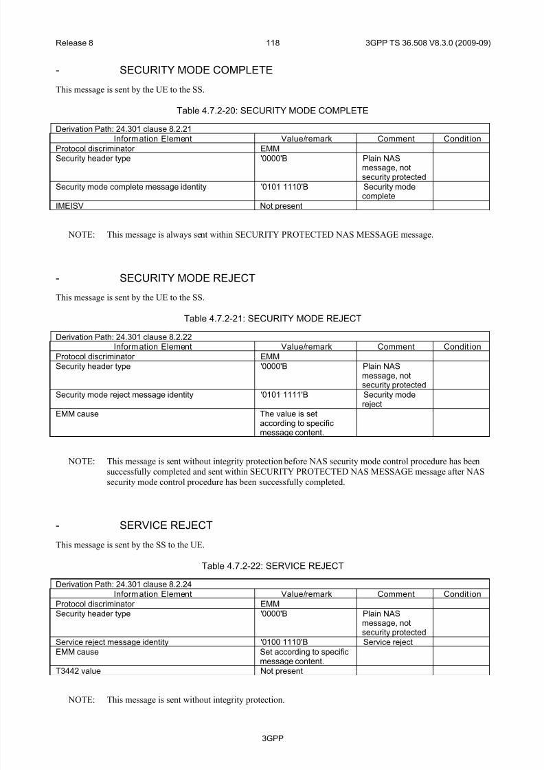
7/15/2019 Lte Sib Info
http://slidepdf.com/reader/full/lte-sib-info 118/187
3GPP
3GPP TS 36.508 V8.3.0 (2009-09)118Release 8
- SECURITY MODE COMPLETE
This message is sent by the UE to the SS.
Table 4.7.2-20: SECURITY MODE COMPLETE
Derivation Path: 24.301 clause 8.2.21
Information Element Value/remark Comment Condit ion
Protocol discriminator EMM
Security header type '0000'B Plain NASmessage, notsecurity protected
Security mode complete message identity '0101 1110'B Security modecomplete
IMEISV Not present
NOTE: This message is always sent within SECURITY PROTECTED NAS MESSAGE message.
- SECURITY MODE REJECT
This message is sent by the UE to the SS.
Table 4.7.2-21: SECURITY MODE REJECT
Derivation Path: 24.301 clause 8.2.22Information Element Value/remark Comment Condit ion
Protocol discriminator EMM
Security header type '0000'B Plain NASmessage, notsecurity protected
Security mode reject message identity '0101 1111'B Security mode
rejectEMM cause The value is set
according to specificmessage content.
NOTE: This message is sent without integrity protection before NAS security mode control procedure has beensuccessfully completed and sent within SECURITY PROTECTED NAS MESSAGE message after NASsecurity mode control procedure has been successfully completed.
- SERVICE REJECT
This message is sent by the SS to the UE.
Table 4.7.2-22: SERVICE REJECT
Derivation Path: 24.301 clause 8.2.24
Information Element Value/remark Comment Condit ion
Protocol discriminator EMM
Security header type '0000'B Plain NASmessage, notsecurity protected
Service reject message identity '0100 1110'B Service reject
EMM cause Set according to specificmessage content.
T3442 value Not present
NOTE: This message is sent without integrity protection.
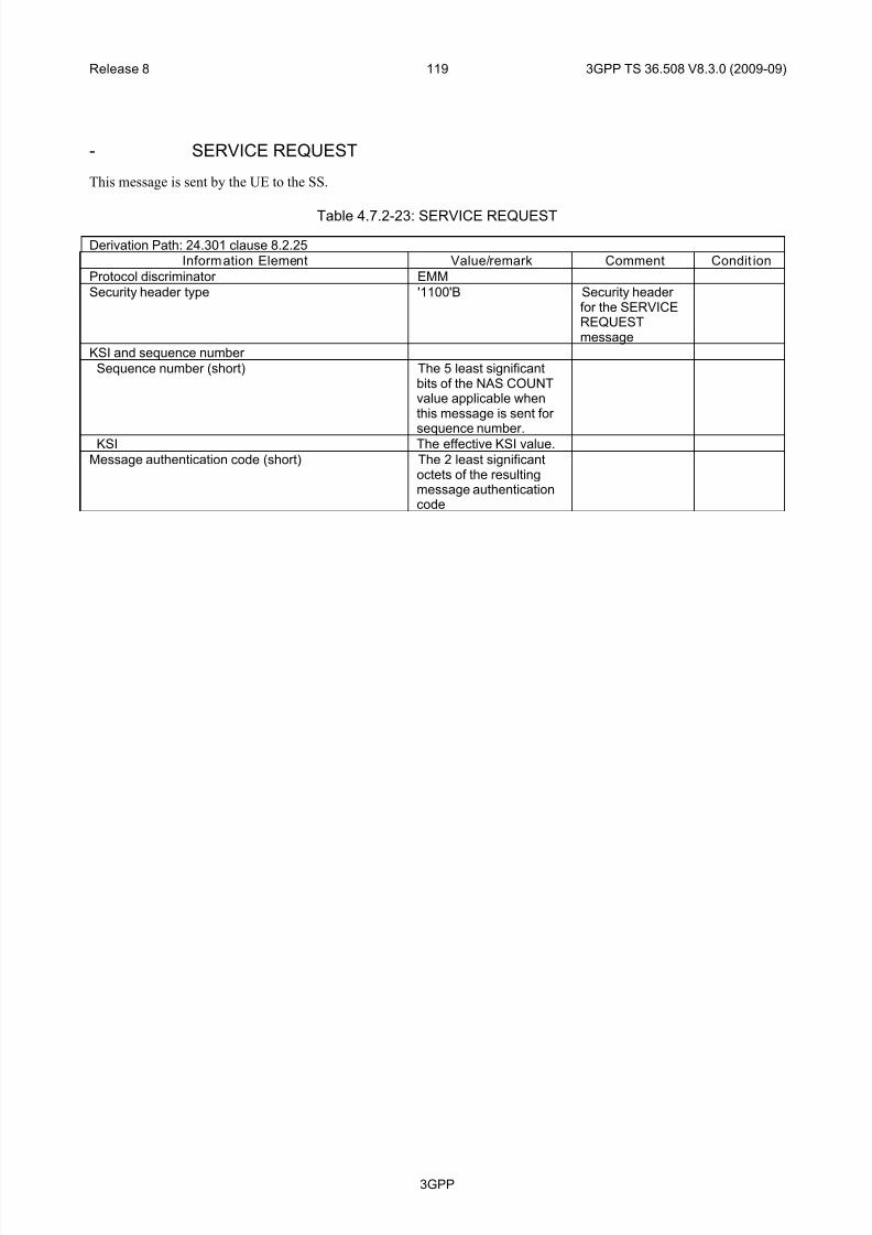
7/15/2019 Lte Sib Info
http://slidepdf.com/reader/full/lte-sib-info 119/187
3GPP
3GPP TS 36.508 V8.3.0 (2009-09)119Release 8
- SERVICE REQUEST
This message is sent by the UE to the SS.
Table 4.7.2-23: SERVICE REQUEST
Derivation Path: 24.301 clause 8.2.25Information Element Value/remark Comment Condit ion
Protocol discriminator EMM
Security header type '1100'B Security header for the SERVICEREQUESTmessage
KSI and sequence number
Sequence number (short) The 5 least significantbits of the NAS COUNTvalue applicable whenthis message is sent for
sequence number.KSI The effective KSI value.
Message authentication code (short) The 2 least significantoctets of the resultingmessage authenticationcode
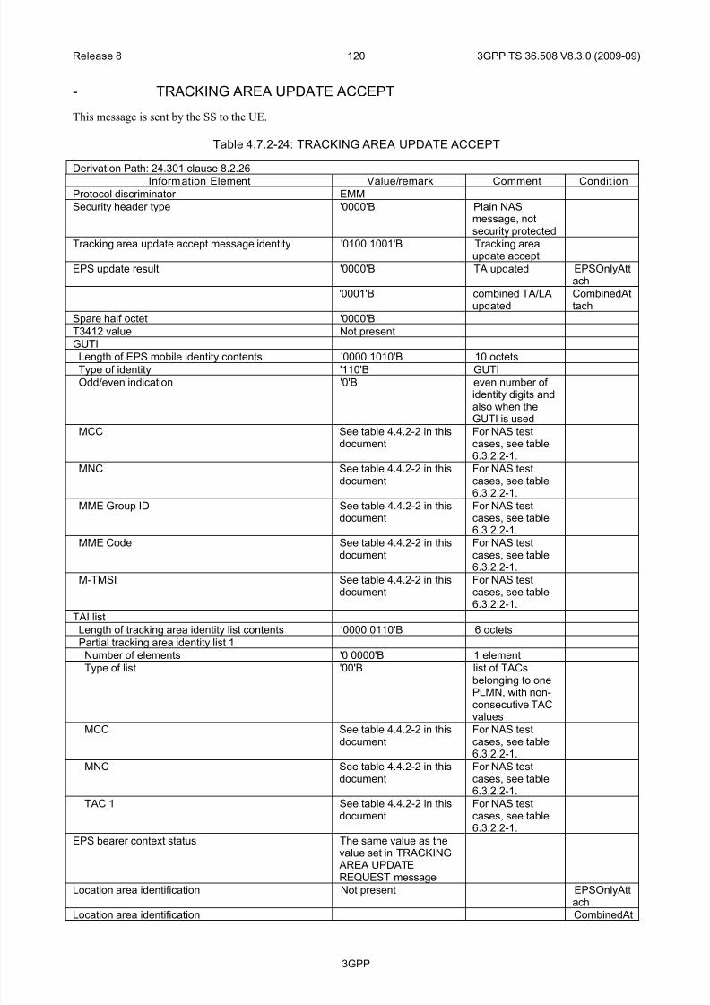
7/15/2019 Lte Sib Info
http://slidepdf.com/reader/full/lte-sib-info 120/187
3GPP
3GPP TS 36.508 V8.3.0 (2009-09)120Release 8
- TRACKING AREA UPDATE ACCEPT
This message is sent by the SS to the UE.
Table 4.7.2-24: TRACKING AREA UPDATE ACCEPT
Derivation Path: 24.301 clause 8.2.26
Information Element Value/remark Comment Condit ion
Protocol discriminator EMM
Security header type '0000'B Plain NASmessage, notsecurity protected
Tracking area update accept message identity '0100 1001'B Tracking areaupdate accept
EPS update result '0000'B TA updated EPSOnlyAttach
'0001'B combined TA/LAupdated
CombinedAttach
Spare half octet '0000'B
T3412 value Not present
GUTILength of EPS mobile identity contents '0000 1010'B 10 octets
Type of identity '110'B GUTI
Odd/even indication '0'B even number of identity digits andalso when theGUTI is used
MCC See table 4.4.2-2 in thisdocument
For NAS testcases, see table6.3.2.2-1.
MNC See table 4.4.2-2 in thisdocument
For NAS testcases, see table6.3.2.2-1.
MME Group ID See table 4.4.2-2 in thisdocument
For NAS testcases, see table6.3.2.2-1.
MME Code See table 4.4.2-2 in thisdocument
For NAS testcases, see table6.3.2.2-1.
M-TMSI See table 4.4.2-2 in thisdocument
For NAS testcases, see table6.3.2.2-1.
TAI list
Length of tracking area identity list contents '0000 0110'B 6 octets
Partial tracking area identity list 1
Number of elements '0 0000'B 1 element
Type of list '00'B list of TACsbelonging to onePLMN, with non-consecutive TACvalues
MCC See table 4.4.2-2 in thisdocument
For NAS testcases, see table6.3.2.2-1.
MNC See table 4.4.2-2 in thisdocument
For NAS testcases, see table6.3.2.2-1.
TAC 1 See table 4.4.2-2 in thisdocument
For NAS testcases, see table6.3.2.2-1.
EPS bearer context status The same value as thevalue set in TRACKING AREA UPDATEREQUEST message
Location area identification Not present EPSOnlyAttach
Location area identification CombinedAt
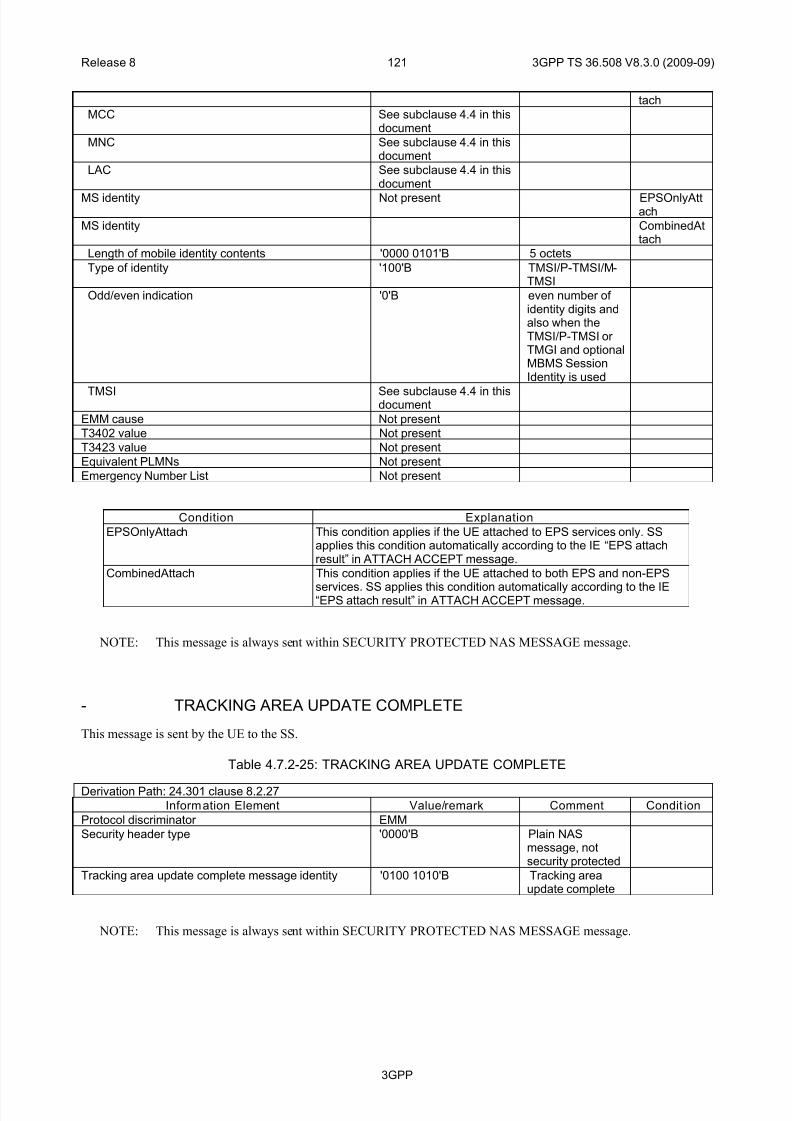
7/15/2019 Lte Sib Info
http://slidepdf.com/reader/full/lte-sib-info 121/187
3GPP
3GPP TS 36.508 V8.3.0 (2009-09)121Release 8
tach
MCC See subclause 4.4 in thisdocument
MNC See subclause 4.4 in thisdocument
LAC See subclause 4.4 in thisdocument
MS identity Not present EPSOnlyAttach
MS identity CombinedAttach
Length of mobile identity contents '0000 0101'B 5 octets
Type of identity '100'B TMSI/P-TMSI/M-TMSI
Odd/even indication '0'B even number of identity digits andalso when theTMSI/P-TMSI or TMGI and optionalMBMS SessionIdentity is used
TMSI See subclause 4.4 in thisdocument
EMM cause Not present
T3402 value Not present
T3423 value Not present
Equivalent PLMNs Not present
Emergency Number List Not present
Condition Explanation
EPSOnlyAttach This condition applies if the UE attached to EPS services only. SSapplies this condition automatically according to the IE “EPS attachresult” in ATTACH ACCEPT message.
CombinedAttach This condition applies if the UE attached to both EPS and non-EPS
services. SS applies this condition automatically according to the IE“EPS attach result” in ATTACH ACCEPT message.
NOTE: This message is always sent within SECURITY PROTECTED NAS MESSAGE message.
- TRACKING AREA UPDATE COMPLETE
This message is sent by the UE to the SS.
Table 4.7.2-25: TRACKING AREA UPDATE COMPLETE
Derivation Path: 24.301 clause 8.2.27
Information Element Value/remark Comment Condit ion
Protocol discriminator EMM
Security header type '0000'B Plain NASmessage, notsecurity protected
Tracking area update complete message identity '0100 1010'B Tracking areaupdate complete
NOTE: This message is always sent within SECURITY PROTECTED NAS MESSAGE message.
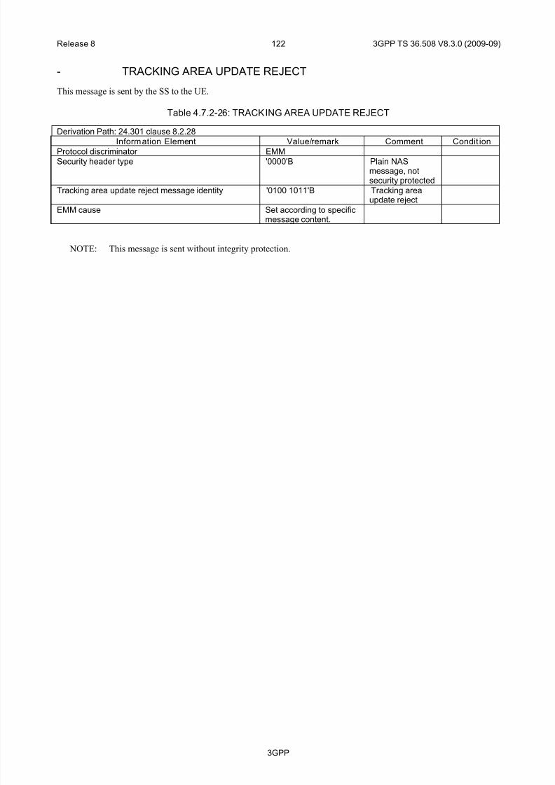
7/15/2019 Lte Sib Info
http://slidepdf.com/reader/full/lte-sib-info 122/187
3GPP
3GPP TS 36.508 V8.3.0 (2009-09)122Release 8
- TRACKING AREA UPDATE REJECT
This message is sent by the SS to the UE.
Table 4.7.2-26: TRACKING AREA UPDATE REJECT
Derivation Path: 24.301 clause 8.2.28
Information Element Value/remark Comment Condit ion
Protocol discriminator EMM
Security header type '0000'B Plain NASmessage, notsecurity protected
Tracking area update reject message identity '0100 1011'B Tracking areaupdate reject
EMM cause Set according to specificmessage content.
NOTE: This message is sent without integrity protection.

7/15/2019 Lte Sib Info
http://slidepdf.com/reader/full/lte-sib-info 123/187
3GPP
3GPP TS 36.508 V8.3.0 (2009-09)123Release 8
- TRACKING AREA UPDATE REQUEST
This message is sent by the UE to the SS.
Table 4.7.2-27: TRACKING AREA UPDATE REQUEST
Derivation Path: 24.301 clause 8.2.29
Information Element Value/remark Comment Condit ion
Protocol discriminator EMM
Security header type '0000'B Plain NASmessage, notsecurity protected
Tracking area update request message identity '0100 1000'B Tracking areaupdate request
EPS update type
EPS update type Value '000'B TA updating EPSOnlyAttach
'001'B Combined TA/LAupdating
CombinedAttach
"Active" flag '0'B No bearer establishmentrequested
NAS key set identifier
NAS key set identifier The valid NAS key setidentifier of the UE
TSC '0'B native securitycontext (for KSI ASME)
Old GUTI Any allowed value
Non-current native NAS key set identifier Not present
GPRS ciphering key sequence number Not present
Old P-TMSI signature Not present
Additional GUTI Not present
NonceUE Not present
UE network capability Not present or anyallowed value
Last visited registered TAI Not present or anyallowed value
DRX parameter Not present
UE radio capability information update needed Not present
EPS bearer context status Any allowed value
MS network capability Not present or anyallowed value
Old location area identification Not present or anyallowed value
TMSI status Not present or anyallowed value
Mobile station classmark 2 Not present or any
allowed valueMobile station classmark 3 Not present or anyallowed value
Supported Codecs Not present or anyallowed value
Condition Explanation
EPSOnlyAttach See the definition below table 4.7.2-24.
CombinedAttach See the definition below table 4.7.2-24.
NOTE: This message is always sent within SECURITY PROTECTED NAS MESSAGE message.
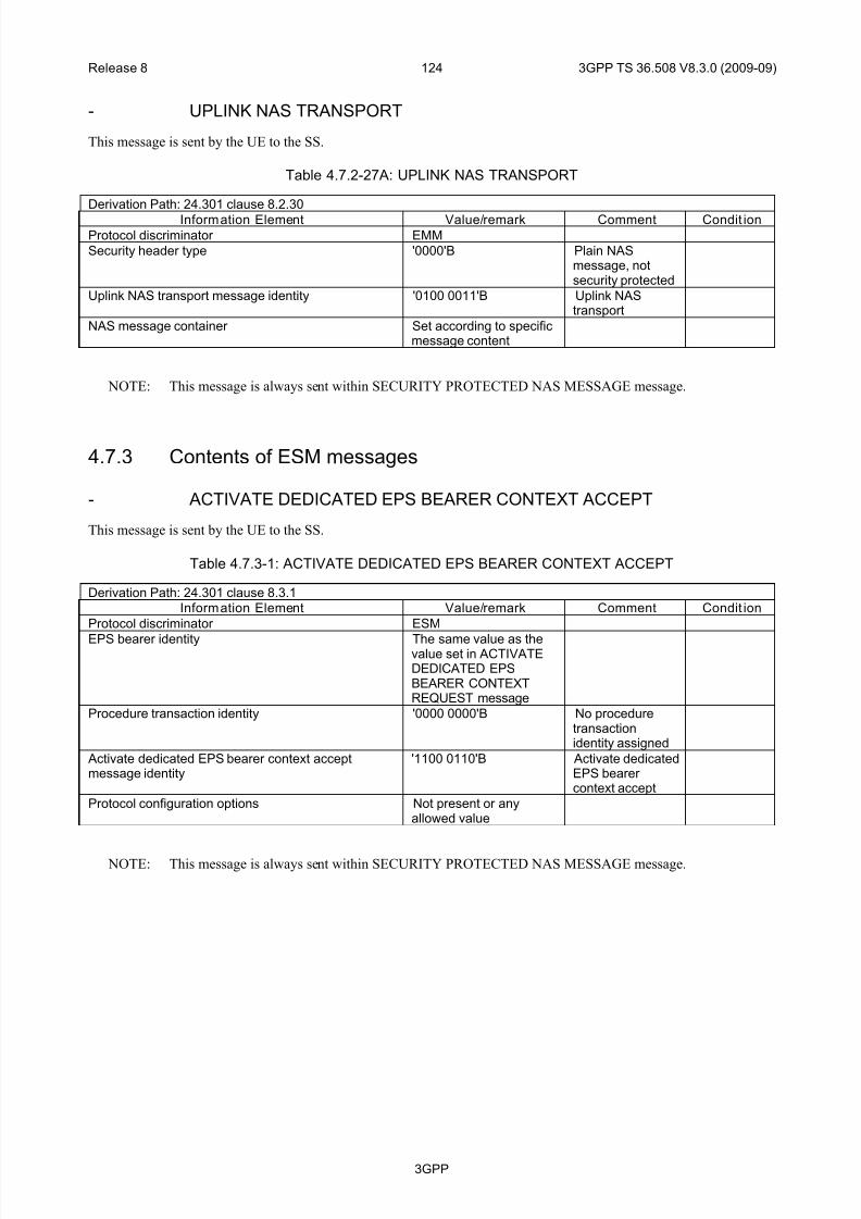
7/15/2019 Lte Sib Info
http://slidepdf.com/reader/full/lte-sib-info 124/187
3GPP
3GPP TS 36.508 V8.3.0 (2009-09)124Release 8
- UPLINK NAS TRANSPORT
This message is sent by the UE to the SS.
Table 4.7.2-27A: UPLINK NAS TRANSPORT
Derivation Path: 24.301 clause 8.2.30
Information Element Value/remark Comment Condit ion
Protocol discriminator EMM
Security header type '0000'B Plain NASmessage, notsecurity protected
Uplink NAS transport message identity '0100 0011'B Uplink NAStransport
NAS message container Set according to specificmessage content
NOTE: This message is always sent within SECURITY PROTECTED NAS MESSAGE message.
4.7.3 Contents of ESM messages
- ACTIVATE DEDICATED EPS BEARER CONTEXT ACCEPT
This message is sent by the UE to the SS.
Table 4.7.3-1: ACTIVATE DEDICATED EPS BEARER CONTEXT ACCEPT
Derivation Path: 24.301 clause 8.3.1Information Element Value/remark Comment Condit ion
Protocol discriminator ESM
EPS bearer identity The same value as thevalue set in ACTIVATEDEDICATED EPSBEARER CONTEXTREQUEST message
Procedure transaction identity '0000 0000'B No proceduretransactionidentity assigned
Activate dedicated EPS bearer context acceptmessage identity
'1100 0110'B Activate dedicatedEPS bearer context accept
Protocol configuration options Not present or anyallowed value
NOTE: This message is always sent within SECURITY PROTECTED NAS MESSAGE message.
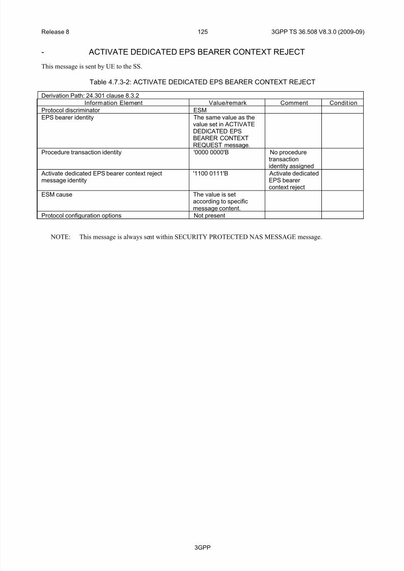
7/15/2019 Lte Sib Info
http://slidepdf.com/reader/full/lte-sib-info 125/187
3GPP
3GPP TS 36.508 V8.3.0 (2009-09)125Release 8
- ACTIVATE DEDICATED EPS BEARER CONTEXT REJECT
This message is sent by UE to the SS.
Table 4.7.3-2: ACTIVATE DEDICATED EPS BEARER CONTEXT REJECT
Derivation Path: 24.301 clause 8.3.2
Information Element Value/remark Comment Condit ion
Protocol discriminator ESM
EPS bearer identity The same value as thevalue set in ACTIVATEDEDICATED EPSBEARER CONTEXTREQUEST message.
Procedure transaction identity '0000 0000'B No proceduretransactionidentity assigned
Activate dedicated EPS bearer context rejectmessage identity
'1100 0111'B Activate dedicatedEPS bearer context reject
ESM cause The value is setaccording to specificmessage content.
Protocol configuration options Not present
NOTE: This message is always sent within SECURITY PROTECTED NAS MESSAGE message.
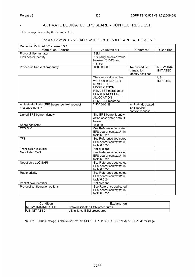
7/15/2019 Lte Sib Info
http://slidepdf.com/reader/full/lte-sib-info 126/187
3GPP
3GPP TS 36.508 V8.3.0 (2009-09)126Release 8
- ACTIVATE DEDICATED EPS BEARER CONTEXT REQUEST
This message is sent by the SS to the UE.
Table 4.7.3-3: ACTIVATE DEDICATED EPS BEARER CONTEXT REQUEST
Derivation Path: 24.301 clause 8.3.3
Information Element Value/remark Comment Condit ion
Protocol discriminator ESM
EPS bearer identity Arbitrarily selected valuebetween '0101'B and'1111'B.
Procedure transaction identity '0000 0000'B No proceduretransactionidentity assigned
NETWORK-INITIATED
The same value as thevalue set in BEARERRESOURCEMODIFICATIONREQUEST message or BEARER RESOURCE ALLOCATIONREQUEST message
UE-INITIATED
Activate dedicated EPS bearer context requestmessage identity
'1100 0101'B Activate dedicatedEPS bearer context request
Linked EPS bearer identity The EPS bearer identityof the associated defaultbearer
Spare half octet '0000'B
EPS QoS See Reference dedicatedEPS bearer context #1 intable 6.6.2-1
TFT See Reference dedicatedEPS bearer context #1 in
table 6.6.2-1Transaction identifier Not present
Negotiated QoS See Reference dedicatedEPS bearer context #1 intable 6.6.2-1
Negotiated LLC SAPI See Reference dedicatedEPS bearer context #1 intable 6.6.2-1
Radio priority See Reference dedicatedEPS bearer context #1 intable 6.6.2-1
Packet flow Identifier Not present
Protocol configuration options See Reference dedicatedEPS bearer context #1 in
table 6.6.2-1
Condition Explanation
NETWORK-INITIATED Network initiated ESM procedures
UE-INITIATED UE initiated ESM procedures
NOTE: This message is always sent within SECURITY PROTECTED NAS MESSAGE message.
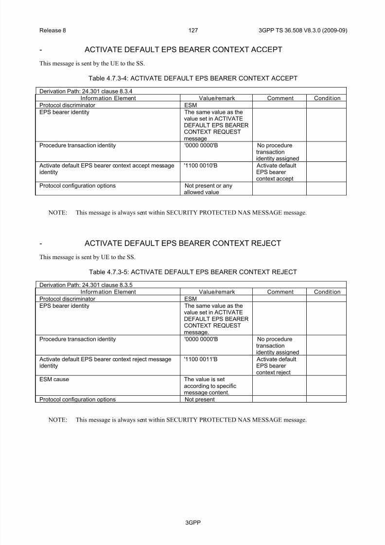
7/15/2019 Lte Sib Info
http://slidepdf.com/reader/full/lte-sib-info 127/187
3GPP
3GPP TS 36.508 V8.3.0 (2009-09)127Release 8
- ACTIVATE DEFAULT EPS BEARER CONTEXT ACCEPT
This message is sent by the UE to the SS.
Table 4.7.3-4: ACTIVATE DEFAULT EPS BEARER CONTEXT ACCEPT
Derivation Path: 24.301 clause 8.3.4
Information Element Value/remark Comment Condit ion
Protocol discriminator ESM
EPS bearer identity The same value as thevalue set in ACTIVATEDEFAULT EPS BEARERCONTEXT REQUESTmessage
Procedure transaction identity '0000 0000'B No proceduretransactionidentity assigned
Activate default EPS bearer context accept messageidentity
'1100 0010'B Activate defaultEPS bearer context accept
Protocol configuration options Not present or anyallowed value
NOTE: This message is always sent within SECURITY PROTECTED NAS MESSAGE message.
- ACTIVATE DEFAULT EPS BEARER CONTEXT REJECT
This message is sent by UE to the SS.
Table 4.7.3-5: ACTIVATE DEFAULT EPS BEARER CONTEXT REJECT
Derivation Path: 24.301 clause 8.3.5Information Element Value/remark Comment Condit ion
Protocol discriminator ESM
EPS bearer identity The same value as thevalue set in ACTIVATEDEFAULT EPS BEARERCONTEXT REQUESTmessage.
Procedure transaction identity '0000 0000'B No proceduretransactionidentity assigned
Activate default EPS bearer context reject messageidentity
'1100 0011'B Activate defaultEPS bearer context reject
ESM cause The value is setaccording to specificmessage content.
Protocol configuration options Not present
NOTE: This message is always sent within SECURITY PROTECTED NAS MESSAGE message.
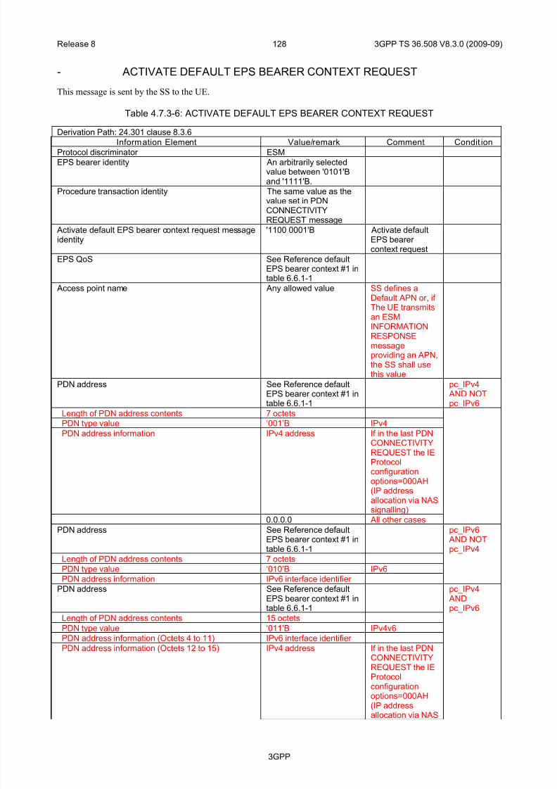
7/15/2019 Lte Sib Info
http://slidepdf.com/reader/full/lte-sib-info 128/187
3GPP
3GPP TS 36.508 V8.3.0 (2009-09)128Release 8
- ACTIVATE DEFAULT EPS BEARER CONTEXT REQUEST
This message is sent by the SS to the UE.
Table 4.7.3-6: ACTIVATE DEFAULT EPS BEARER CONTEXT REQUEST
Derivation Path: 24.301 clause 8.3.6
Information Element Value/remark Comment Condit ion
Protocol discriminator ESM
EPS bearer identity An arbitrarily selectedvalue between '0101'Band '1111'B.
Procedure transaction identity The same value as thevalue set in PDNCONNECTIVITYREQUEST message
Activate default EPS bearer context request messageidentity
'1100 0001'B Activate defaultEPS bearer context request
EPS QoS See Reference defaultEPS bearer context #1 intable 6.6.1-1
Access point name Any allowed value SS defines aDefault APN or, if The UE transmitsan ESMINFORMATIONRESPONSEmessageproviding an APN,the SS shall usethis value
PDN address See Reference defaultEPS bearer context #1 intable 6.6.1-1
pc_IPv4 AND NOTpc_IPv6
Length of PDN address contents 7 octets PDN type value ‘001’B IPv4
PDN address information IPv4 address If in the last PDNCONNECTIVITYREQUEST the IEProtocolconfigurationoptions=000AH(IP addressallocation via NASsignalling)
0.0.0.0 All other cases
PDN address See Reference defaultEPS bearer context #1 in
table 6.6.1-1
pc_IPv6 AND NOT
pc_IPv4 Length of PDN address contents 7 octets
PDN type value ‘010’B IPv6
PDN address information IPv6 interface identifier
PDN address See Reference defaultEPS bearer context #1 intable 6.6.1-1
pc_IPv4 ANDpc_IPv6
Length of PDN address contents 15 octets
PDN type value ‘011’B IPv4v6
PDN address information (Octets 4 to 11) IPv6 interface identifier
PDN address information (Octets 12 to 15) IPv4 address If in the last PDNCONNECTIVITYREQUEST the IEProtocol
configurationoptions=000AH(IP addressallocation via NAS
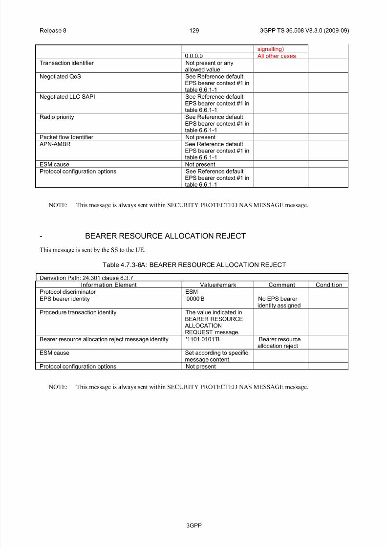
7/15/2019 Lte Sib Info
http://slidepdf.com/reader/full/lte-sib-info 129/187
3GPP
3GPP TS 36.508 V8.3.0 (2009-09)129Release 8
signalling)
0.0.0.0 All other cases
Transaction identifier Not present or anyallowed value
Negotiated QoS See Reference defaultEPS bearer context #1 intable 6.6.1-1
Negotiated LLC SAPI See Reference defaultEPS bearer context #1 intable 6.6.1-1
Radio priority See Reference defaultEPS bearer context #1 intable 6.6.1-1
Packet flow Identifier Not present
APN-AMBR See Reference defaultEPS bearer context #1 intable 6.6.1-1
ESM cause Not present
Protocol configuration options See Reference defaultEPS bearer context #1 intable 6.6.1-1
NOTE: This message is always sent within SECURITY PROTECTED NAS MESSAGE message.
- BEARER RESOURCE ALLOCATION REJECT
This message is sent by the SS to the UE.
Table 4.7.3-6A: BEARER RESOURCE ALLOCATION REJECT
Derivation Path: 24.301 clause 8.3.7
Information Element Value/remark Comment Condit ionProtocol discriminator ESM
EPS bearer identity '0000'B No EPS bearer identity assigned
Procedure transaction identity The value indicated inBEARER RESOURCE ALLOCATIONREQUEST message.
Bearer resource allocation reject message identity '1101 0101'B Bearer resourceallocation reject
ESM cause Set according to specificmessage content.
Protocol configuration options Not present
NOTE: This message is always sent within SECURITY PROTECTED NAS MESSAGE message.
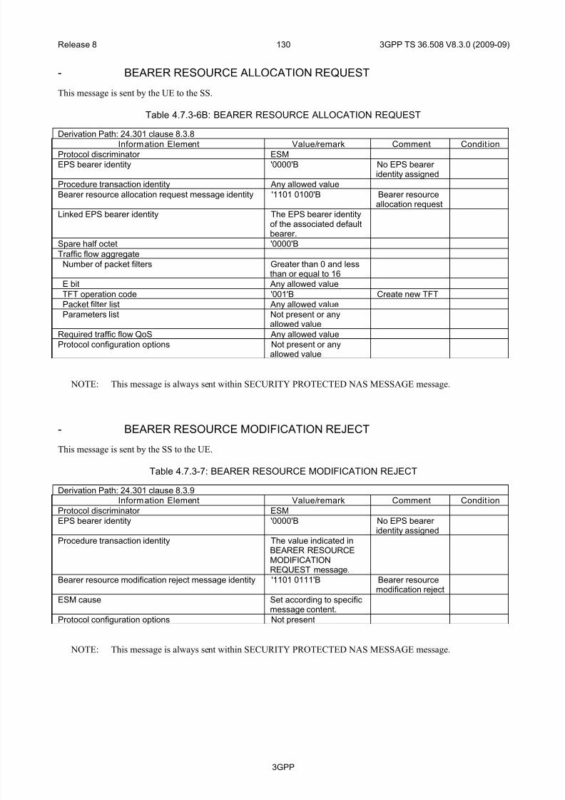
7/15/2019 Lte Sib Info
http://slidepdf.com/reader/full/lte-sib-info 130/187
3GPP
3GPP TS 36.508 V8.3.0 (2009-09)130Release 8
- BEARER RESOURCE ALLOCATION REQUEST
This message is sent by the UE to the SS.
Table 4.7.3-6B: BEARER RESOURCE ALLOCATION REQUEST
Derivation Path: 24.301 clause 8.3.8
Information Element Value/remark Comment Condit ion
Protocol discriminator ESM
EPS bearer identity '0000'B No EPS bearer identity assigned
Procedure transaction identity Any allowed value
Bearer resource allocation request message identity '1101 0100'B Bearer resourceallocation request
Linked EPS bearer identity The EPS bearer identityof the associated defaultbearer.
Spare half octet '0000'B
Traffic flow aggregate
Number of packet filters Greater than 0 and less
than or equal to 16E bit Any allowed value
TFT operation code '001'B Create new TFT
Packet filter list Any allowed value
Parameters list Not present or anyallowed value
Required traffic flow QoS Any allowed value
Protocol configuration options Not present or anyallowed value
NOTE: This message is always sent within SECURITY PROTECTED NAS MESSAGE message.
- BEARER RESOURCE MODIFICATION REJECT
This message is sent by the SS to the UE.
Table 4.7.3-7: BEARER RESOURCE MODIFICATION REJECT
Derivation Path: 24.301 clause 8.3.9Information Element Value/remark Comment Condit ion
Protocol discriminator ESM
EPS bearer identity '0000'B No EPS bearer identity assigned
Procedure transaction identity The value indicated inBEARER RESOURCEMODIFICATIONREQUEST message.
Bearer resource modification reject message identity '1101 0111'B Bearer resourcemodification reject
ESM cause Set according to specificmessage content.
Protocol configuration options Not present
NOTE: This message is always sent within SECURITY PROTECTED NAS MESSAGE message.
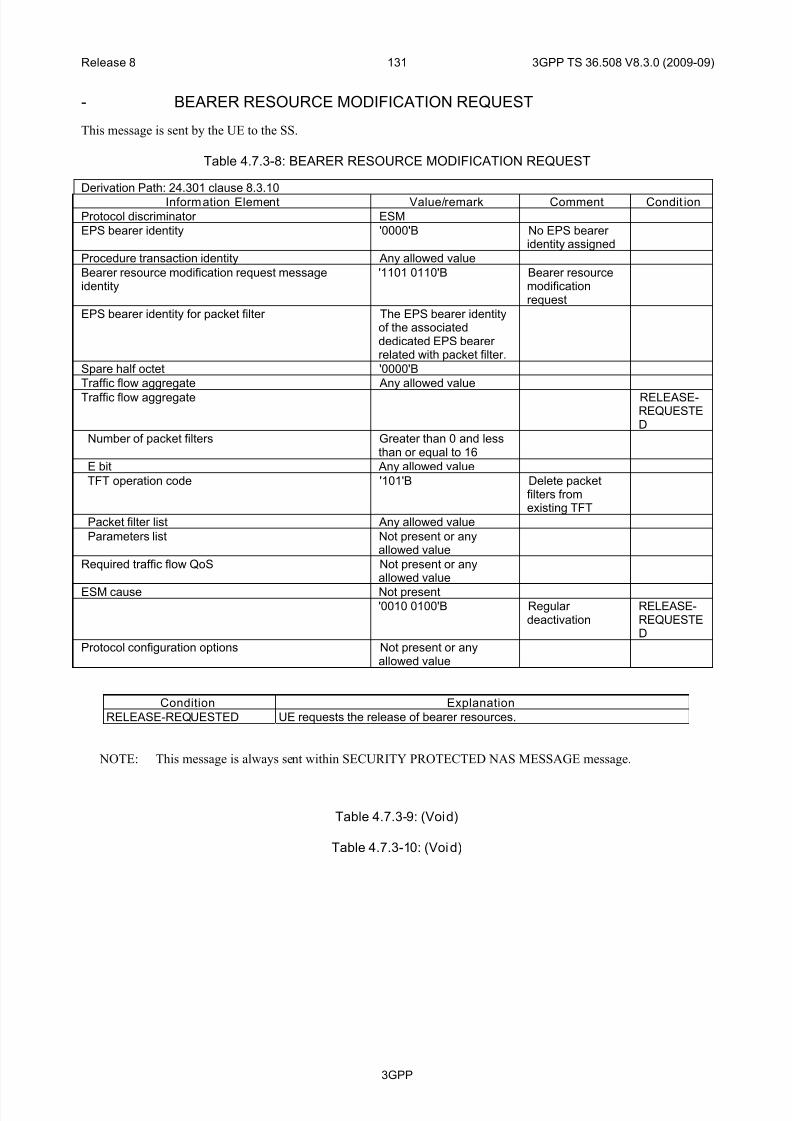
7/15/2019 Lte Sib Info
http://slidepdf.com/reader/full/lte-sib-info 131/187
3GPP
3GPP TS 36.508 V8.3.0 (2009-09)131Release 8
- BEARER RESOURCE MODIFICATION REQUEST
This message is sent by the UE to the SS.
Table 4.7.3-8: BEARER RESOURCE MODIFICATION REQUEST
Derivation Path: 24.301 clause 8.3.10
Information Element Value/remark Comment Condit ion
Protocol discriminator ESM
EPS bearer identity '0000'B No EPS bearer identity assigned
Procedure transaction identity Any allowed value
Bearer resource modification request messageidentity
'1101 0110'B Bearer resourcemodificationrequest
EPS bearer identity for packet filter The EPS bearer identityof the associateddedicated EPS bearer related with packet filter.
Spare half octet '0000'B
Traffic flow aggregate Any allowed value
Traffic flow aggregate RELEASE-REQUESTED
Number of packet filters Greater than 0 and lessthan or equal to 16
E bit Any allowed value
TFT operation code '101'B Delete packetfilters fromexisting TFT
Packet filter list Any allowed value
Parameters list Not present or anyallowed value
Required traffic flow QoS Not present or anyallowed value
ESM cause Not present
'0010 0100'B Regular deactivation
RELEASE-REQUESTED
Protocol configuration options Not present or anyallowed value
Condition Explanation
RELEASE-REQUESTED UE requests the release of bearer resources.
NOTE: This message is always sent within SECURITY PROTECTED NAS MESSAGE message.
Table 4.7.3-9: (Void)
Table 4.7.3-10: (Void)
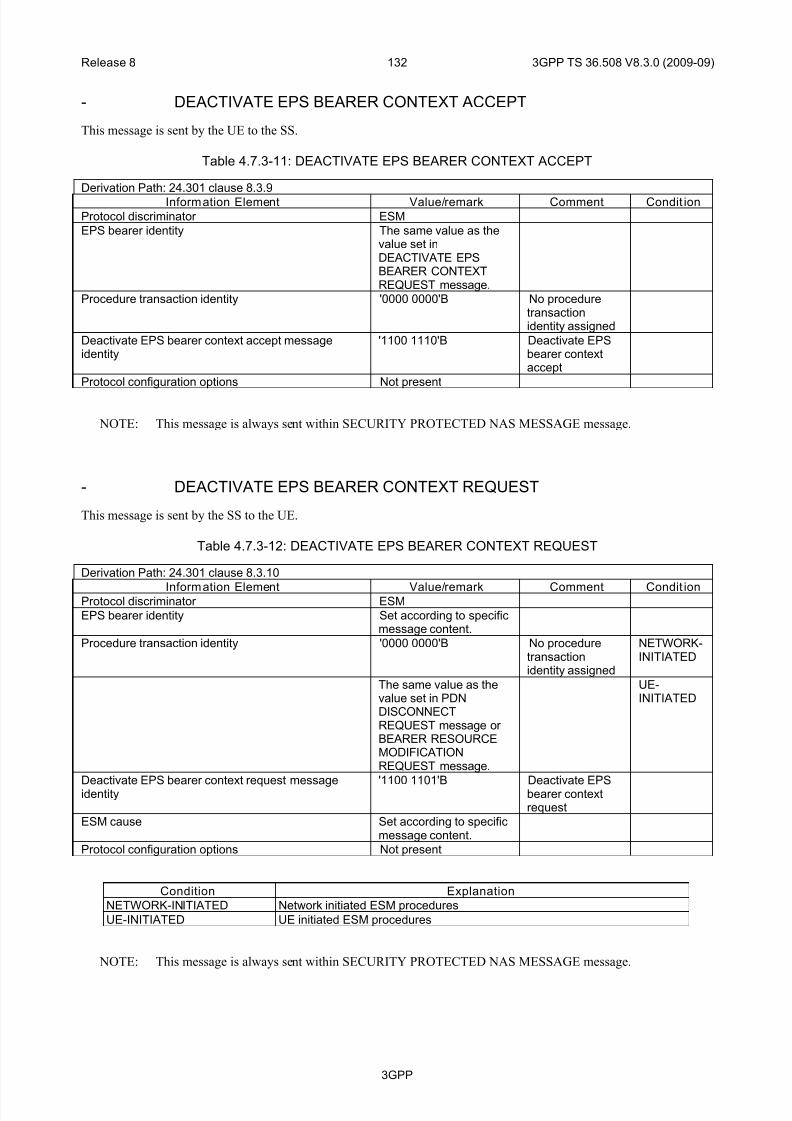
7/15/2019 Lte Sib Info
http://slidepdf.com/reader/full/lte-sib-info 132/187
3GPP
3GPP TS 36.508 V8.3.0 (2009-09)132Release 8
- DEACTIVATE EPS BEARER CONTEXT ACCEPT
This message is sent by the UE to the SS.
Table 4.7.3-11: DEACTIVATE EPS BEARER CONTEXT ACCEPT
Derivation Path: 24.301 clause 8.3.9
Information Element Value/remark Comment Condit ion
Protocol discriminator ESM
EPS bearer identity The same value as thevalue set inDEACTIVATE EPSBEARER CONTEXTREQUEST message.
Procedure transaction identity '0000 0000'B No proceduretransactionidentity assigned
Deactivate EPS bearer context accept messageidentity
'1100 1110'B Deactivate EPSbearer contextaccept
Protocol configuration options Not present
NOTE: This message is always sent within SECURITY PROTECTED NAS MESSAGE message.
- DEACTIVATE EPS BEARER CONTEXT REQUEST
This message is sent by the SS to the UE.
Table 4.7.3-12: DEACTIVATE EPS BEARER CONTEXT REQUEST
Derivation Path: 24.301 clause 8.3.10
Information Element Value/remark Comment Condit ionProtocol discriminator ESM
EPS bearer identity Set according to specificmessage content.
Procedure transaction identity '0000 0000'B No proceduretransactionidentity assigned
NETWORK-INITIATED
The same value as thevalue set in PDNDISCONNECTREQUEST message or BEARER RESOURCEMODIFICATIONREQUEST message.
UE-INITIATED
Deactivate EPS bearer context request messageidentity
'1100 1101'B Deactivate EPSbearer contextrequest
ESM cause Set according to specificmessage content.
Protocol configuration options Not present
Condition Explanation
NETWORK-INITIATED Network initiated ESM procedures
UE-INITIATED UE initiated ESM procedures
NOTE: This message is always sent within SECURITY PROTECTED NAS MESSAGE message.
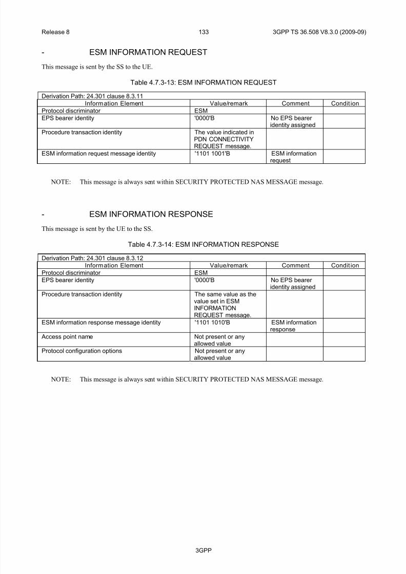
7/15/2019 Lte Sib Info
http://slidepdf.com/reader/full/lte-sib-info 133/187
3GPP
3GPP TS 36.508 V8.3.0 (2009-09)133Release 8
- ESM INFORMATION REQUEST
This message is sent by the SS to the UE.
Table 4.7.3-13: ESM INFORMATION REQUEST
Derivation Path: 24.301 clause 8.3.11
Information Element Value/remark Comment Condit ion
Protocol discriminator ESM
EPS bearer identity '0000'B No EPS bearer identity assigned
Procedure transaction identity The value indicated inPDN CONNECTIVITYREQUEST message.
ESM information request message identity '1101 1001'B ESM informationrequest
NOTE: This message is always sent within SECURITY PROTECTED NAS MESSAGE message.
- ESM INFORMATION RESPONSE
This message is sent by the UE to the SS.
Table 4.7.3-14: ESM INFORMATION RESPONSE
Derivation Path: 24.301 clause 8.3.12
Information Element Value/remark Comment Condit ion
Protocol discriminator ESM
EPS bearer identity '0000'B No EPS bearer identity assigned
Procedure transaction identity The same value as the
value set in ESMINFORMATIONREQUEST message.
ESM information response message identity '1101 1010'B ESM informationresponse
Access point name Not present or anyallowed value
Protocol configuration options Not present or anyallowed value
NOTE: This message is always sent within SECURITY PROTECTED NAS MESSAGE message.
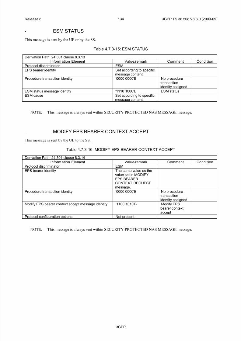
7/15/2019 Lte Sib Info
http://slidepdf.com/reader/full/lte-sib-info 134/187
3GPP
3GPP TS 36.508 V8.3.0 (2009-09)134Release 8
- ESM STATUS
This message is sent by the UE or by the SS.
Table 4.7.3-15: ESM STATUS
Derivation Path: 24.301 clause 8.3.13
Information Element Value/remark Comment Condit ion
Protocol discriminator ESM
EPS bearer identity Set according to specificmessage content.
Procedure transaction identity '0000 0000'B No proceduretransactionidentity assigned
ESM status message identity '1110 1000'B ESM status
ESM cause Set according to specificmessage content.
NOTE: This message is always sent within SECURITY PROTECTED NAS MESSAGE message.
- MODIFY EPS BEARER CONTEXT ACCEPT
This message is sent by the UE to the SS.
Table 4.7.3-16: MODIFY EPS BEARER CONTEXT ACCEPT
Derivation Path: 24.301 clause 8.3.14
Information Element Value/remark Comment Condit ion
Protocol discriminator ESM
EPS bearer identity The same value as thevalue set in MODIFY
EPS BEARERCONTEXT REQUESTmessage.
Procedure transaction identity '0000 0000'B No proceduretransactionidentity assigned
Modify EPS bearer context accept message identity '1100 1010'B Modify EPSbearer contextaccept
Protocol configuration options Not present
NOTE: This message is always sent within SECURITY PROTECTED NAS MESSAGE message.

7/15/2019 Lte Sib Info
http://slidepdf.com/reader/full/lte-sib-info 135/187
3GPP
3GPP TS 36.508 V8.3.0 (2009-09)135Release 8
- MODIFY EPS BEARER CONTEXT REJECT
This message is sent by the UE to the SS.
Table 4.7.3-17: MODIFY EPS BEARER CONTEXT REJECT
Derivation Path: 24.301 clause 8.3.15
Information Element Value/remark Comment Condit ion
Protocol discriminator ESM
EPS bearer identity The same value as thevalue set in MODIFYEPS BEARERCONTEXT REQUESTmessage.
Procedure transaction identity '0000 0000'B No proceduretransactionidentity assigned
Modify EPS bearer context reject message identity '1100 1011'B Modify EPSbearer contextreject
ESM cause The value is setaccording to specificmessage content.
Protocol configuration options Not present
NOTE: This message is always sent within SECURITY PROTECTED NAS MESSAGE message.

7/15/2019 Lte Sib Info
http://slidepdf.com/reader/full/lte-sib-info 136/187
3GPP
3GPP TS 36.508 V8.3.0 (2009-09)136Release 8
- MODIFY EPS BEARER CONTEXT REQUEST
This message is sent by the SS to the UE.
Table 4.7.3-18: MODIFY EPS BEARER CONTEXT REQUEST
Derivation Path: 24.301 clause 8.3.16
Information Element Value/remark Comment Condit ion
Protocol discriminator ESM
EPS bearer identity Set according to specificmessage content.
Procedure transaction identity '0000 0000'B No proceduretransactionidentity assigned
NETWORK-INITIATED
The same value as thevalue set in BEARERRESOURCEMODIFICATIONREQUEST message or BEARER RESOURCE ALLOCATIONREQUEST message.
UE-INITIATED
Modify EPS bearer context request message identity '1100 1001'B Modify EPSbearer contextrequest
New EPS QoS For a default EPS bearer,see subclause 6.6.1.For a dedicated EPSbearer, see subclause6.6.2.
TFT For a default EPS bearer,see subclause 6.6.1.For a dedicated EPSbearer, see subclause6.6.2.
New QoS For a default EPS bearer,see subclause 6.6.1.For a dedicated EPSbearer, see subclause6.6.2.
Negotiated LLC SAPI For a default EPS bearer,see subclause 6.6.1.For a dedicated EPSbearer, see subclause6.6.2.
Radio priority For a default EPS bearer,see subclause 6.6.1.For a dedicated EPSbearer, see subclause
6.6.2.Packet flow Identifier For a default EPS bearer,
see subclause 6.6.1.For a dedicated EPSbearer, see subclause6.6.2.
APN-AMBR For a default EPS bearer,see subclause 6.6.1.For a dedicated EPSbearer, see subclause6.6.2.
Protocol configuration options Not present
Condition ExplanationNETWORK-INITIATED Network initiated ESM procedures
UE-INITIATED UE initiated ESM procedures

7/15/2019 Lte Sib Info
http://slidepdf.com/reader/full/lte-sib-info 137/187
3GPP
3GPP TS 36.508 V8.3.0 (2009-09)137Release 8
NOTE: This message is always sent within SECURITY PROTECTED NAS MESSAGE message.
- PDN CONNECTIVITY REJECT
This message is sent by the SS to the UE.
Table 4.7.3-19: PDN CONNECTIVITY REJECT
Derivation Path: 24.301 clause 8.3.17
Information Element Value/remark Comment Condit ion
Protocol discriminator ESM
EPS bearer identity '0000'B No EPS bearer identity assigned
Procedure transaction identity The same value as thevalue set in PDNCONNECTIVITYREQUEST message.
PDN connectivity reject message identity '1101 0001'B PDN connectivity
rejectESM cause The value is set
according to specificmessage content.
Protocol configuration options Not present
NOTE: This message is sent without integrity protection.
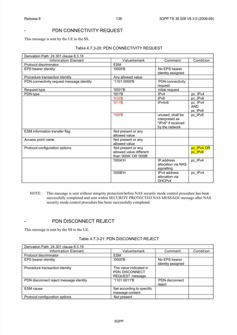
7/15/2019 Lte Sib Info
http://slidepdf.com/reader/full/lte-sib-info 138/187
3GPP
3GPP TS 36.508 V8.3.0 (2009-09)138Release 8
- PDN CONNECTIVITY REQUEST
This message is sent by the UE to the SS.
Table 4.7.3-20: PDN CONNECTIVITY REQUEST
Derivation Path: 24.301 clause 8.3.18
Information Element Value/remark Comment Condit ion
Protocol discriminator ESM
EPS bearer identity '0000'B No EPS bearer identity assigned
Procedure transaction identity Any allowed value
PDN connectivity request message identity '1101 0000'B PDN connectivityrequest
Request type '0001'B initial request
PDN type '001'B IPv4 pc_IPv4
'010'B IPv6 pc_IPv6
'011'B IPv4v6 pc_IPv4 ANDpc_IPv6
'100'B unused; shall beinterpreted as"IPv6" if receivedby the network
pc_IPv6
ESM information transfer flag Not present or anyallowed value
Access point name Not present or anyallowed value
Protocol configuration options Not present or anyallowed value differentthan '000A' OR '000B'
pc_IPv4 ORpc_IPv6
'000A'H IP addressallocation via NASsignalling
pc_IPv4
'000B'H IPv4 addressallocation viaDHCPv4
pc_IPv4
NOTE: This message is sent without integrity protection before NAS security mode control procedure has beensuccessfully completed and sent within SECURITY PROTECTED NAS MESSAGE message after NASsecurity mode control procedure has been successfully completed.
- PDN DISCONNECT REJECT
This message is sent by the SS to the UE.
Table 4.7.3-21: PDN DISCONNECT REJECT
Derivation Path: 24.301 clause 8.3.19
Information Element Value/remark Comment Condit ion
Protocol discriminator ESM
EPS bearer identity '0000'B No EPS bearer identity assigned
Procedure transaction identity The value indicated inPDN DISCONNECTREQUEST message.
PDN disconnect reject message identity '1101 0011'B PDN disconnectreject
ESM cause Set according to specificmessage content.
Protocol configuration options Not present
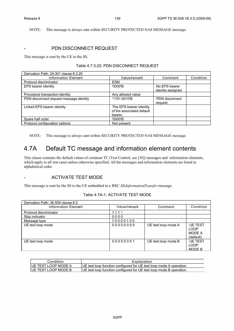
7/15/2019 Lte Sib Info
http://slidepdf.com/reader/full/lte-sib-info 139/187
3GPP
3GPP TS 36.508 V8.3.0 (2009-09)139Release 8
NOTE: This message is always sent within SECURITY PROTECTED NAS MESSAGE message.
- PDN DISCONNECT REQUEST
This message is sent by the UE to the SS.
Table 4.7.3-22: PDN DISCONNECT REQUEST
Derivation Path: 24.301 clause 8.3.20
Information Element Value/remark Comment Condit ion
Protocol discriminator ESM
EPS bearer identity '0000'B No EPS bearer identity assigned
Procedure transaction identity Any allowed value
PDN disconnect request message identity '1101 0010'B PDN disconnectrequest
Linked EPS bearer identity The EPS bearer identityof the associated default
bearer.Spare half octet '0000'B
Protocol configuration options Not present
NOTE: This message is always sent within SECURITY PROTECTED NAS MESSAGE message.
4.7A Default TC message and information element contents
This clause contains the default values of common TC (Test Control, see [38]) messages and information elements,which apply to all test cases unless otherwise specified. All the messages and information elements are listed inalphabetical order.
- ACTIVATE TEST MODE
This message is sent by the SS to the UE embedded in a RRC DLInformationTransfer message.
Table 4.7A-1: ACTIVATE TEST MODE
Derivation Path: 36.509 clause 6.5Information Element Value/remark Comment Condit ion
Protocol discriminator 1 1 1 1
Skip indicator 0 0 0 0
Message type 1 0 0 0 0 1 0 0
UE test loop mode 0 0 0 0 0 0 0 0 UE test loop mode A UE TEST
LOOPMODE A(default)
UE test loop mode 0 0 0 0 0 0 0 1 UE test loop mode B UE TESTLOOPMODE B
Condition Explanation
UE TEST LOOP MODE A UE test loop function configured for UE test loop mode A operation.
UE TEST LOOP MODE B UE test loop function configured for UE test loop mode B operation.

7/15/2019 Lte Sib Info
http://slidepdf.com/reader/full/lte-sib-info 140/187
3GPP
3GPP TS 36.508 V8.3.0 (2009-09)140Release 8
- ACTIVATE TEST MODE COMPLETE
This message is sent by the UE to the SS embedded in a RRC ULInformationTransfer message.
Table 4.7A-2: ACTIVATE TEST MODE COMPLETE
Derivation Path: 36.509 clause 6.6
Information Element Value/remark Comment Condit ion
Protocol discriminator 1 1 1 1
Skip indicator 0 0 0 0
Message type 1 0 0 0 0 1 0 1
- CLOSE UE TEST LOOP
This message is sent by the SS to the UE embedded in a RRC DLInformationTransfer message.
Table 4.7A-3: CLOSE UE TEST LOOP
Derivation Path: 36.509 clause 6.1Information Element Value/remark Comment Condit ion
Protocol discriminator 1 1 1 1
Skip indicator 0 0 0 0
Message type 1 0 0 0 0 0 0 0
UE test loop mode 0 0 0 0 0 0 0 0 UE test loop mode A
UE test loop mode A LB setup
Length of UE test loop mode A LB setup list in bytes 0 No LB setup list. Noscaling (UL RLC SDUsize will be equal to thereceived DL SDU size)
UE test loop mode B LB setup Not present
UE TESTLOOPMODE A(default)
UE test loop mode 0 0 0 0 0 0 0 1 UE test loop mode B
UE test loop mode A LB setup Not present
UE test loop mode B LB setupIP PDU delay 0 0 0 0 0 0 0 0 No delay
UE TESTLOOP
MODE B
Condition Explanation
UE TEST LOOP MODE A UE test loop function configured for UE test loop mode A operation.
UE TEST LOOP MODE B UE test loop function configured for UE test loop mode B operation.
- CLOSE UE TEST LOOP COMPLETE
This message is sent by the UE to the SS embedded in a RRC ULInformationTransfer message.
Table 4.7A-4: CLOSE UE TEST LOOP
Derivation Path: 36.509 clause 6.2
Information Element Value/remark Comment Condit ion
Protocol discriminator 1 1 1 1
Skip indicator 0 0 0 0
Message type 1 0 0 0 0 0 0 1
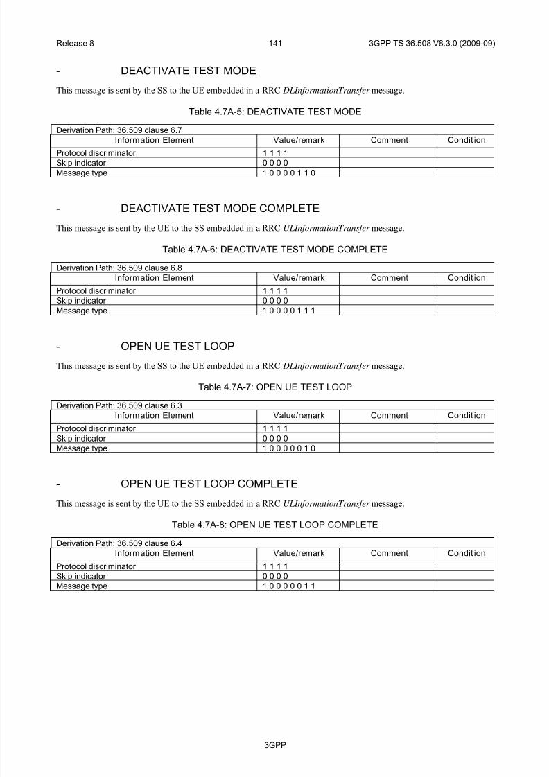
7/15/2019 Lte Sib Info
http://slidepdf.com/reader/full/lte-sib-info 141/187
3GPP
3GPP TS 36.508 V8.3.0 (2009-09)141Release 8
- DEACTIVATE TEST MODE
This message is sent by the SS to the UE embedded in a RRC DLInformationTransfer message.
Table 4.7A-5: DEACTIVATE TEST MODE
Derivation Path: 36.509 clause 6.7
Information Element Value/remark Comment Condit ion
Protocol discriminator 1 1 1 1
Skip indicator 0 0 0 0
Message type 1 0 0 0 0 1 1 0
- DEACTIVATE TEST MODE COMPLETE
This message is sent by the UE to the SS embedded in a RRC ULInformationTransfer message.
Table 4.7A-6: DEACTIVATE TEST MODE COMPLETE
Derivation Path: 36.509 clause 6.8Information Element Value/remark Comment Condit ion
Protocol discriminator 1 1 1 1
Skip indicator 0 0 0 0
Message type 1 0 0 0 0 1 1 1
- OPEN UE TEST LOOP
This message is sent by the SS to the UE embedded in a RRC DLInformationTransfer message.
Table 4.7A-7: OPEN UE TEST LOOP
Derivation Path: 36.509 clause 6.3Information Element Value/remark Comment Condit ion
Protocol discriminator 1 1 1 1
Skip indicator 0 0 0 0
Message type 1 0 0 0 0 0 1 0
- OPEN UE TEST LOOP COMPLETE
This message is sent by the UE to the SS embedded in a RRC ULInformationTransfer message.
Table 4.7A-8: OPEN UE TEST LOOP COMPLETE
Derivation Path: 36.509 clause 6.4Information Element Value/remark Comment Condit ion
Protocol discriminator 1 1 1 1
Skip indicator 0 0 0 0
Message type 1 0 0 0 0 0 1 1
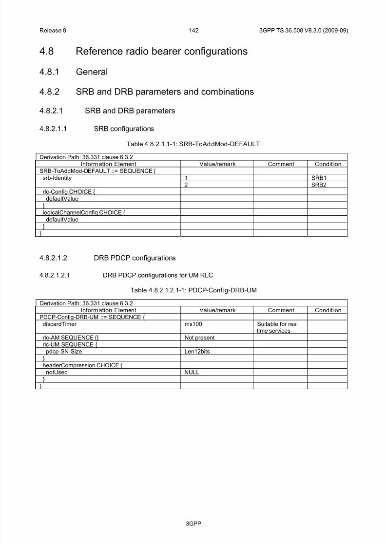
7/15/2019 Lte Sib Info
http://slidepdf.com/reader/full/lte-sib-info 142/187
3GPP
3GPP TS 36.508 V8.3.0 (2009-09)142Release 8
4.8 Reference radio bearer configurations
4.8.1 General
4.8.2 SRB and DRB parameters and combinations
4.8.2.1 SRB and DRB parameters
4.8.2.1.1 SRB configurations
Table 4.8.2.1.1-1: SRB-ToAddMod-DEFAULT
Derivation Path: 36.331 clause 6.3.2
Information Element Value/remark Comment Condit ion
SRB-ToAddMod-DEFAULT ::= SEQUENCE {
srb-Identity 1 SRB1
2 SRB2
rlc-Config CHOICE {defaultValue
}
logicalChannelConfig CHOICE {
defaultValue
}
}
4.8.2.1.2 DRB PDCP configurations
4.8.2.1.2.1 DRB PDCP configurations for UM RLC
Table 4.8.2.1.2.1-1: PDCP-Config-DRB-UM
Derivation Path: 36.331 clause 6.3.2
Information Element Value/remark Comment Condit ion
PDCP-Config-DRB-UM ::= SEQUENCE {
discardTimer ms100 Suitable for realtime services
rlc-AM SEQUENCE {} Not present
rlc-UM SEQUENCE {
pdcp-SN-Size Len12bits
}
headerCompression CHOICE {
notUsed NULL
}}

7/15/2019 Lte Sib Info
http://slidepdf.com/reader/full/lte-sib-info 143/187
3GPP
3GPP TS 36.508 V8.3.0 (2009-09)143Release 8
4.8.2.1.2.2 DRB PDCP configurations for AM RLC
Table 4.8.2.1.2.2-1: PDCP-Config-DRB-AM
Derivation Path: 36.331 clause 6.3.2
Information Element Value/remark Comment Condit ion
PDCP-Config-DRB-AM ::= SEQUENCE {
discardTimer Infinity
rlc-AM SEQUENCE {
statusReportRequired TRUE
}
rlc-UM SEQUENCE {} Not present
headerCompression CHOICE {
notUsed NULL
}
}
4.8.2.1.3 DRB RLC configurations
4.8.2.1.3.1 DRB UM RLC configurations
Table 4.8.2.1.3.1-1: RLC-Config-DRB-UM
Derivation Path: 36.331 clause 6.3.2
Information Element Value/remark Comment Condit ion
RLC-Config-DRB-UM ::= CHOICE {
um-Bi-Directional SEQUENCE {
ul-UM-RLC SEQUENCE {
sn-FieldLength Size10
}
dl-UM-RLC SEQUENCE {
sn-FieldLength Size10
t-Reordering ms50 ms50 providessufficient margin
}
}
}
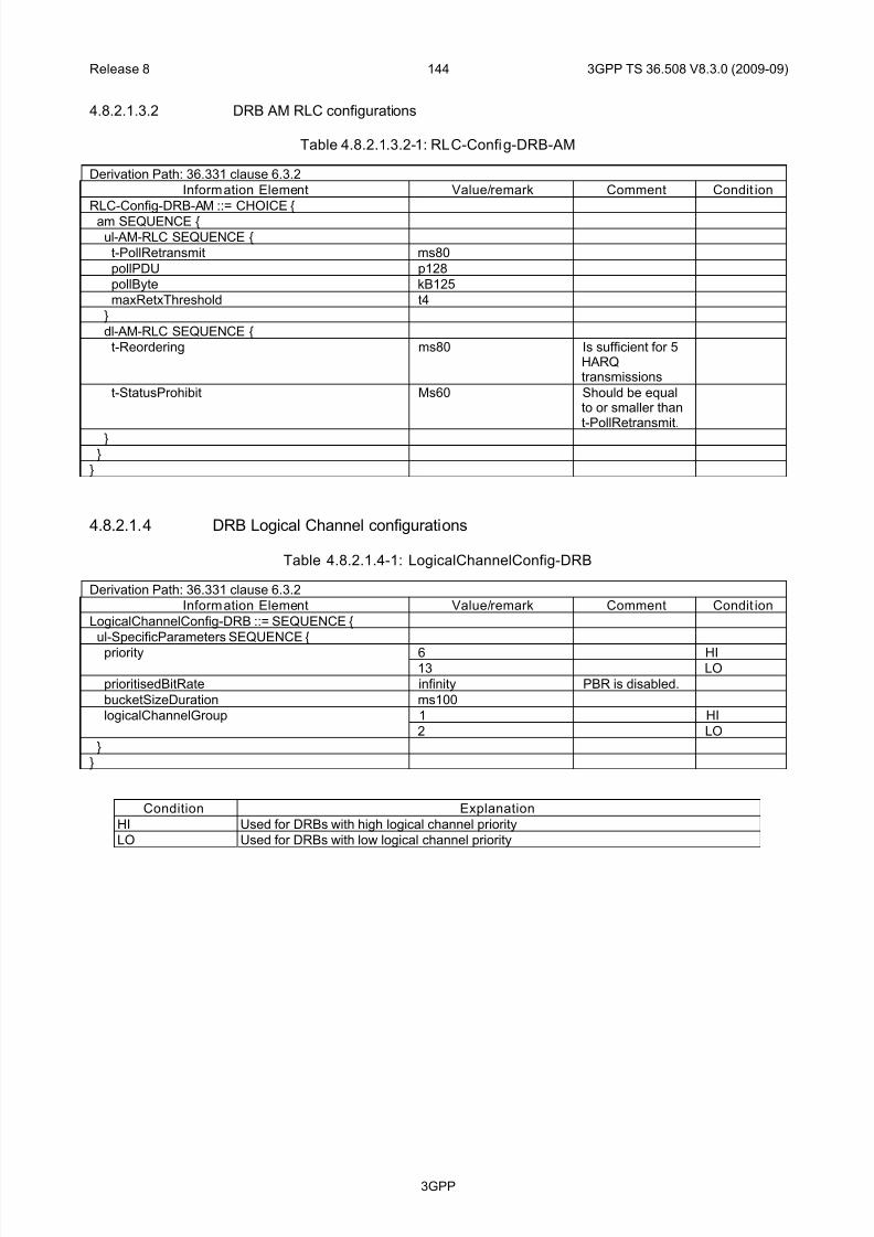
7/15/2019 Lte Sib Info
http://slidepdf.com/reader/full/lte-sib-info 144/187
3GPP
3GPP TS 36.508 V8.3.0 (2009-09)144Release 8
4.8.2.1.3.2 DRB AM RLC configurations
Table 4.8.2.1.3.2-1: RLC-Conf ig-DRB-AM
Derivation Path: 36.331 clause 6.3.2
Information Element Value/remark Comment Condit ion
RLC-Config-DRB-AM ::= CHOICE {
am SEQUENCE {
ul-AM-RLC SEQUENCE {
t-PollRetransmit ms80
pollPDU p128
pollByte kB125
maxRetxThreshold t4
}
dl-AM-RLC SEQUENCE {
t-Reordering ms80 Is sufficient for 5HARQtransmissions
t-StatusProhibit Ms60 Should be equalto or smaller thant-PollRetransmit.
}
}
}
4.8.2.1.4 DRB Logical Channel configurations
Table 4.8.2.1.4-1: LogicalChannelConfig-DRB
Derivation Path: 36.331 clause 6.3.2
Information Element Value/remark Comment Condit ion
LogicalChannelConfig-DRB ::= SEQUENCE {
ul-SpecificParameters SEQUENCE {
priority 6 HI
13 LO
prioritisedBitRate infinity PBR is disabled.
bucketSizeDuration ms100
logicalChannelGroup 1 HI
2 LO
}
}
Condition Explanation
HI Used for DRBs with high logical channel priority
LO Used for DRBs with low logical channel priority
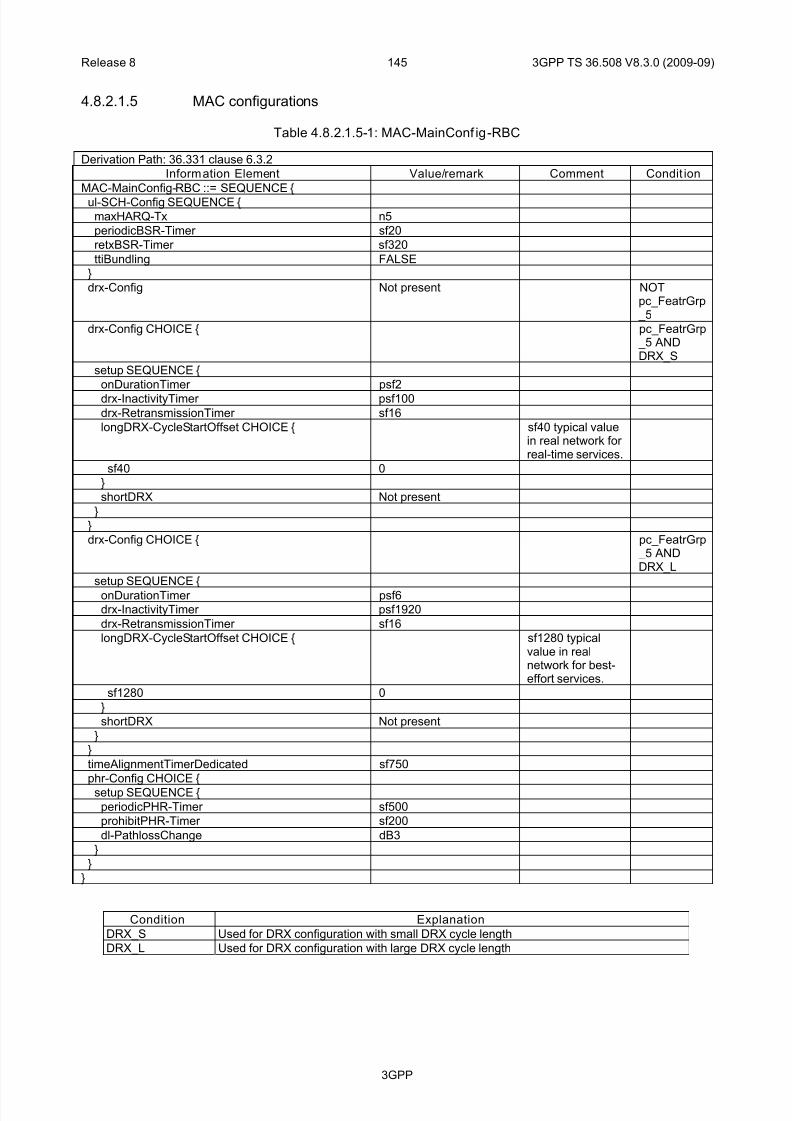
7/15/2019 Lte Sib Info
http://slidepdf.com/reader/full/lte-sib-info 145/187
3GPP
3GPP TS 36.508 V8.3.0 (2009-09)145Release 8
4.8.2.1.5 MAC configurations
Table 4.8.2.1.5-1: MAC-MainConfig-RBC
Derivation Path: 36.331 clause 6.3.2
Information Element Value/remark Comment Condit ion
MAC-MainConfig-RBC ::= SEQUENCE {
ul-SCH-Config SEQUENCE {
maxHARQ-Tx n5
periodicBSR-Timer sf20
retxBSR-Timer sf320
ttiBundling FALSE
}
drx-Config Not present NOTpc_FeatrGrp _5
drx-Config CHOICE { pc_FeatrGrp _5 ANDDRX_S
setup SEQUENCE {
onDurationTimer psf2drx-InactivityTimer psf100
drx-RetransmissionTimer sf16
longDRX-CycleStartOffset CHOICE { sf40 typical valuein real network for real-time services.
sf40 0
}
shortDRX Not present
}
}
drx-Config CHOICE { pc_FeatrGrp _5 ANDDRX_L
setup SEQUENCE {onDurationTimer psf6drx-InactivityTimer psf1920
drx-RetransmissionTimer sf16
longDRX-CycleStartOffset CHOICE { sf1280 typicalvalue in realnetwork for best-effort services.
sf1280 0
}
shortDRX Not present
}
}
timeAlignmentTimerDedicated sf750
phr-Config CHOICE {setup SEQUENCE {
periodicPHR-Timer sf500
prohibitPHR-Timer sf200
dl-PathlossChange dB3
}
}
}
Condition Explanation
DRX_S Used for DRX configuration with small DRX cycle length
DRX_L Used for DRX configuration with large DRX cycle length

7/15/2019 Lte Sib Info
http://slidepdf.com/reader/full/lte-sib-info 146/187
3GPP
3GPP TS 36.508 V8.3.0 (2009-09)146Release 8
Table 4.8.2.1.5-2: MAC-MainConfig-SRB
Derivation Path: 36.331 clause 6.3.2Information Element Value/remark Comment Condit ion
MAC-MainConfig-SRB ::= SEQUENCE {
ul-SCH-Config SEQUENCE {
maxHARQ-Tx n5
periodicBSR-Timer sf20retxBSR-Timer sf320
ttiBundling FALSE
}
drx-Config CHOICE {
release NULL
}
timeAlignmentTimerDedicated sf750
phr-Config CHOICE {
setup SEQUENCE {
periodicPHR-Timer sf500
prohibitPHR-Timer sf200
dl-PathlossChange dB3
}}
}
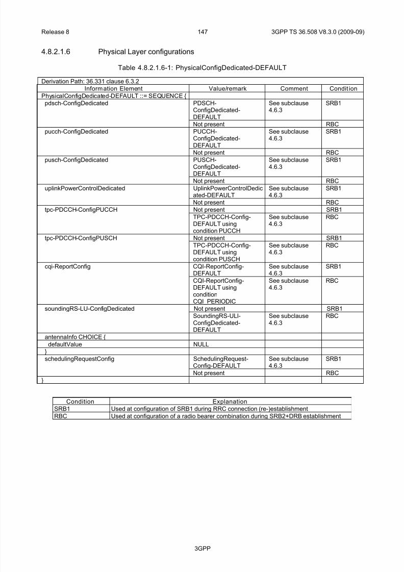
7/15/2019 Lte Sib Info
http://slidepdf.com/reader/full/lte-sib-info 147/187
3GPP
3GPP TS 36.508 V8.3.0 (2009-09)147Release 8
4.8.2.1.6 Physical Layer configurations
Table 4.8.2.1.6-1: PhysicalConfigDedicated-DEFAULT
Derivation Path: 36.331 clause 6.3.2
Information Element Value/remark Comment Condit ion
PhysicalConfigDedicated-DEFAULT ::= SEQUENCE {
pdsch-ConfigDedicated PDSCH-ConfigDedicated-DEFAULT
See subclause4.6.3
SRB1
Not present RBC
pucch-ConfigDedicated PUCCH-ConfigDedicated-DEFAULT
See subclause4.6.3
SRB1
Not present RBC
pusch-ConfigDedicated PUSCH-ConfigDedicated-DEFAULT
See subclause4.6.3
SRB1
Not present RBC
uplinkPowerControlDedicated UplinkPowerControlDedicated-DEFAULT
See subclause4.6.3
SRB1
Not present RBC
tpc-PDCCH-ConfigPUCCH Not present SRB1
TPC-PDCCH-Config-DEFAULT usingcondition PUCCH
See subclause4.6.3
RBC
tpc-PDCCH-ConfigPUSCH Not present SRB1
TPC-PDCCH-Config-DEFAULT usingcondition PUSCH
See subclause4.6.3
RBC
cqi-ReportConfig CQI-ReportConfig-DEFAULT
See subclause4.6.3
SRB1
CQI-ReportConfig-DEFAULT usingconditionCQI_PERIODIC
See subclause4.6.3
RBC
soundingRS-LU-ConfigDedicated Not present SRB1
SoundingRS-ULl-ConfigDedicated-DEFAULT
See subclause4.6.3
RBC
antennaInfo CHOICE {
defaultValue NULL
}
schedulingRequestConfig SchedulingRequest-Config-DEFAULT
See subclause4.6.3
SRB1
Not present RBC
}
Condition Explanation
SRB1 Used at configuration of SRB1 during RRC connection (re-)establishment
RBC Used at configuration of a radio bearer combination during SRB2+DRB establishment
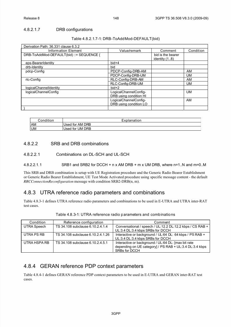
7/15/2019 Lte Sib Info
http://slidepdf.com/reader/full/lte-sib-info 148/187
3GPP
3GPP TS 36.508 V8.3.0 (2009-09)148Release 8
4.8.2.1.7 DRB configurations
Table 4.8.2.1.7-1: DRB-ToAddMod-DEFAULT(bid)
Derivation Path: 36.331 clause 6.3.2
Information Element Value/remark Comment Condit ion
DRB-ToAddMod-DEFAULT(bid) ::= SEQUENCE { bid is the bearer identity (1..8)
eps-BearerIdentity bid+4
drb-Identity bid
pdcp-Config PDCP-Config-DRB-AM AM
PDCP-Config-DRB-UM UM
rlc-Config RLC-Config-DRB-AM AM
RLC-Config-DRB-UM UM
logicalChannelIdentity bid+2
logicalChannelConfig LogicalChannelConfig-DRB using condition HI
UM
LogicalChannelConfig-DRB using condition LO
AM
}
Condition Explanation
AM Used for AM DRB
UM Used for UM DRB
4.8.2.2 SRB and DRB combinations
4.8.2.2.1 Combinations on DL-SCH and UL-SCH
4.8.2.2.1.1 SRB1 and SRB2 for DCCH + n x AM DRB + m x UM DRB, where n=1..N and m=0..M
This SRB and DRB combination is setup with UE Registration procedure and the Generic Radio Bearer Establishmentor Generic Radio Bearer Establishment, UE Test Mode Activated procedure using specific message content - the default
RRCConnectionReconfiguration message with condition SRB2-DRB(n, m).
4.8.3 UTRA reference radio parameters and combinations
Table 4.8.3-1 defines UTRA reference radio parameters and combinations to be used in E-UTRA and UTRA inter-RATtest cases.
Table 4.8.3-1: UTRA reference radio parameters and combinations
Condition Reference configuration Comment
UTRA Speech TS 34.108 subclause 6.10.2.4.1.4 Conversational / speech / UL:12.2 DL:12.2 kbps / CS RAB +UL:3.4 DL:3.4 kbps SRBs for DCCH
UTRA PS RB TS 34.108 subclause 6.10.2.4.1.26 Interactive or background / UL:64 DL: 64 kbps / PS RAB +UL:3.4 DL:3.4 kbps SRBs for DCCH
UTRA HSPA RB TS 34.108 subclause 6.10.2.4.5.1 Interactive or background / UL:64 DL: [max bit ratedepending on UE category] / PS RAB + UL:3.4 DL:3.4 kbpsSRBs for DCCH
4.8.4 GERAN reference PDP context parameters
Table 4.8.4-1 defines GERAN reference PDP context parameters to be used in E-UTRA and GERAN inter-RAT testcases.
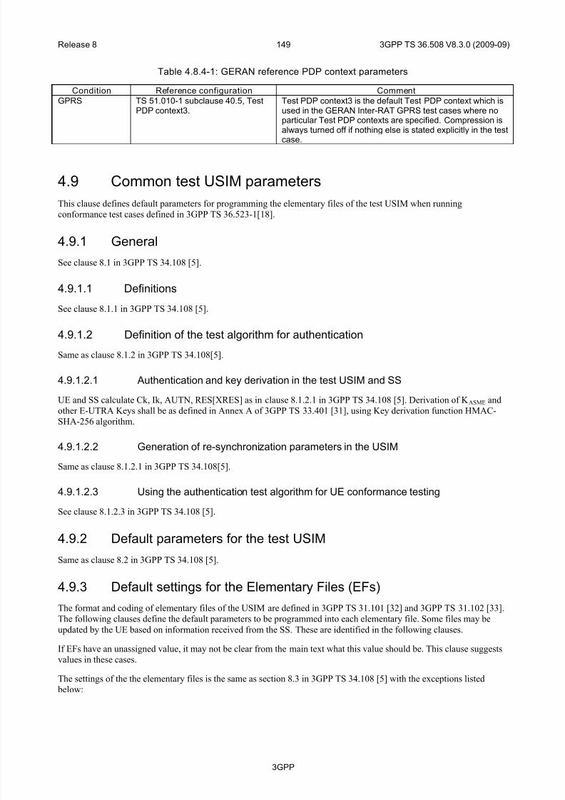
7/15/2019 Lte Sib Info
http://slidepdf.com/reader/full/lte-sib-info 149/187
3GPP
3GPP TS 36.508 V8.3.0 (2009-09)149Release 8
Table 4.8.4-1: GERAN reference PDP context parameters
Condition Reference configuration Comment
GPRS TS 51.010-1 subclause 40.5, TestPDP context3.
Test PDP context3 is the default Test PDP context which isused in the GERAN Inter-RAT GPRS test cases where noparticular Test PDP contexts are specified. Compression isalways turned off if nothing else is stated explicitly in the test
case.
4.9 Common test USIM parameters
This clause defines default parameters for programming the elementary files of the test USIM when runningconformance test cases defined in 3GPP TS 36.523-1[18].
4.9.1 General
See clause 8.1 in 3GPP TS 34.108 [5].
4.9.1.1 Definitions
See clause 8.1.1 in 3GPP TS 34.108 [5].
4.9.1.2 Definition of the test algorithm for authentication
Same as clause 8.1.2 in 3GPP TS 34.108[5].
4.9.1.2.1 Authentication and key derivation in the test USIM and SS
UE and SS calculate Ck, Ik, AUTN, RES[XRES] as in clause 8.1.2.1 in 3GPP TS 34.108 [5]. Derivation of K ASME andother E-UTRA Keys shall be as defined in Annex A of 3GPP TS 33.401 [31], using Key derivation function HMAC-SHA-256 algorithm.
4.9.1.2.2 Generation of re-synchronization parameters in the USIM
Same as clause 8.1.2.1 in 3GPP TS 34.108[5].
4.9.1.2.3 Using the authentication test algorithm for UE conformance testing
See clause 8.1.2.3 in 3GPP TS 34.108 [5].
4.9.2 Default parameters for the test USIM
Same as clause 8.2 in 3GPP TS 34.108 [5].
4.9.3 Default settings for the Elementary Files (EFs)
The format and coding of elementary files of the USIM are defined in 3GPP TS 31.101 [32] and 3GPP TS 31.102 [33].The following clauses define the default parameters to be programmed into each elementary file. Some files may beupdated by the UE based on information received from the SS. These are identified in the following clauses.
If EFs have an unassigned value, it may not be clear from the main text what this value should be. This clause suggestsvalues in these cases.
The settings of the the elementary files is the same as section 8.3 in 3GPP TS 34.108 [5] with the exceptions listed below:
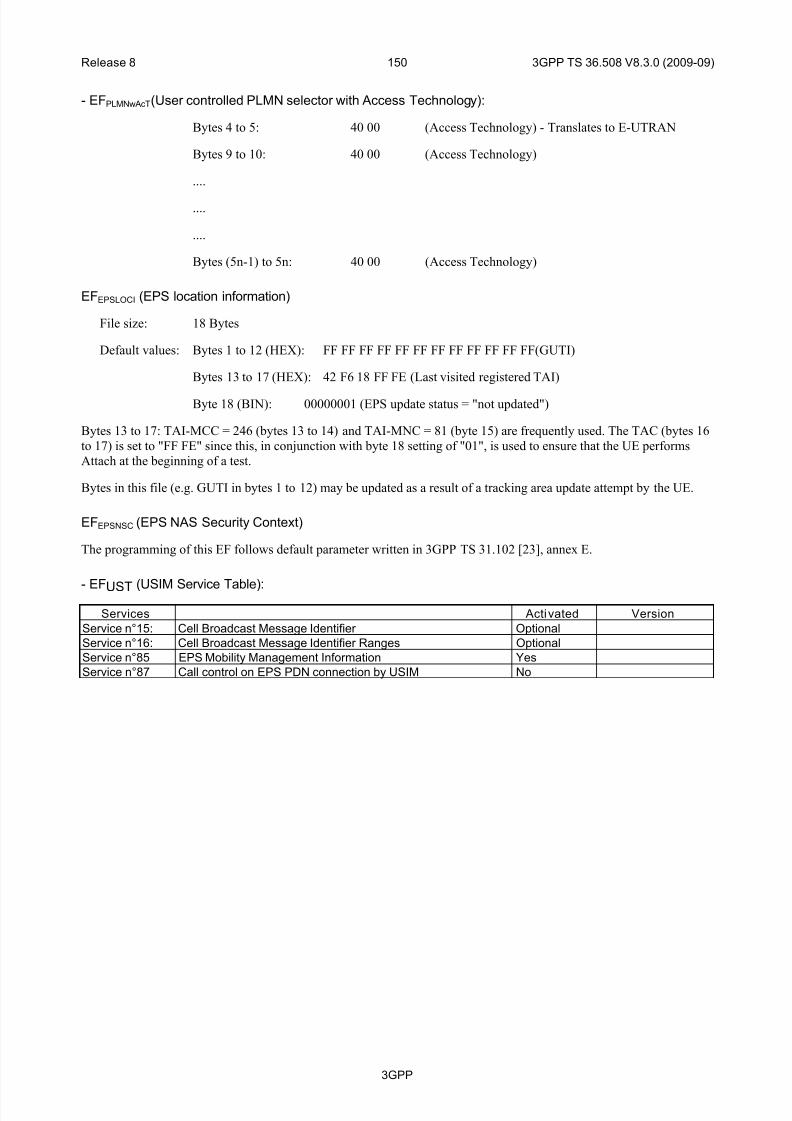
7/15/2019 Lte Sib Info
http://slidepdf.com/reader/full/lte-sib-info 150/187
3GPP
3GPP TS 36.508 V8.3.0 (2009-09)150Release 8
- EFPLMNwAcT(User controlled PLMN selector with Access Technology):
Bytes 4 to 5: 40 00 (Access Technology) - Translates to E-UTRAN
Bytes 9 to 10: 40 00 (Access Technology)
....
....
....
Bytes (5n-1) to 5n: 40 00 (Access Technology)
EFEPSLOCI (EPS location information)
File size: 18 Bytes
Default values: Bytes 1 to 12 (HEX): FF FF FF FF FF FF FF FF FF FF FF FF(GUTI)
Bytes 13 to 17 (HEX): 42 F6 18 FF FE (Last visited registered TAI)
Byte 18 (BIN): 00000001 (EPS update status = "not updated")
Bytes 13 to 17: TAI-MCC = 246 (bytes 13 to 14) and TAI-MNC = 81 (byte 15) are frequently used. The TAC (bytes 16to 17) is set to "FF FE" since this, in conjunction with byte 18 setting of "01", is used to ensure that the UE performsAttach at the beginning of a test.
Bytes in this file (e.g. GUTI in bytes 1 to 12) may be updated as a result of a tracking area update attempt by the UE.
EFEPSNSC (EPS NAS Security Context)
The programming of this EF follows default parameter written in 3GPP TS 31.102 [23], annex E.
- EFUST (USIM Service Table):
Services Activated Version
Service n°15: Cell Broadcast Message Identifier Optional
Service n°16: Cell Broadcast Message Identifier Ranges Optional
Service n°85 EPS Mobility Management Information Yes
Service n°87 Call control on EPS PDN connection by USIM No

7/15/2019 Lte Sib Info
http://slidepdf.com/reader/full/lte-sib-info 151/187
3GPP
3GPP TS 36.508 V8.3.0 (2009-09)151Release 8
5 Test environment for RF test
-
This section contains all the exceptions of the common test parameters specified in clause 4 for specific needs of testcases defined in TS 36.521-1 [21].
5.1 Requirements of test equipment
No common RF test environment requirements are specified in addition to the common requirements described inclause 4.2. Specific RF requirements are indicated within the test cases defined in TS 36.521-1 [21].
5.2 RF/RRM Reference system configurations
5.2.1 Common parameters for simulated E-UTRA cells
5.2.1.1 Combinations of system information blocks
The combinations of system information blocks for test cases in TS 36.521-1 [21] is defined in table 5.2-1.1-1.
Table 5.2.1.1-1: Combinations of system information blocks
System information block type
Combination No. SIB2 SIB3 SIB4 SIB5 SIB6 SIB7 SIB8 SIB9 SIB10 SIB11
1 X X
2 X X X
3 X X X
4 X X X
5 X X X6 X X X
5.2.1.2 Scheduling of system information blocks
The scheduling configurations for combinations of system information blocks are defined in the following tables. SIB1will be transmitted during subframes#5 which SFN mod 2 = 0, and SIB2+SIB3 will be transmitted duringsubframes#5 which SFN mod 2 != 01 with 8 radio frames periodicity.
Table 5.2.1.2-1: Scheduling for combination 1
SchedulingInformation No.
Periodicity[radio frames]
Mapping of system informationblocks
1 8 SIB2, SIB3
Table 5.2.1.2-2: Scheduling for combination 2
SchedulingInformation No.
Periodicity[radio frames]
Mapping of system informationblocks
1 8 SIB2, SIB3
2 64 SIB4

7/15/2019 Lte Sib Info
http://slidepdf.com/reader/full/lte-sib-info 152/187
3GPP
3GPP TS 36.508 V8.3.0 (2009-09)152Release 8
Table 5.2.1.2-3: Scheduling for combination 3
SchedulingInformation No.
Periodicity[radio frames]
Mapping of system informationblocks
1 8 SIB2, SIB3
2 64 SIB5
Table 5.2.1.2-4: Scheduling for combination 4
SchedulingInformation No.
Periodicity[radio frames]
Mapping of system informationblocks
1 8 SIB2, SIB3
2 64 SIB6
Table 5.2.1.2-5: Scheduling for combination 5
SchedulingInformation No.
Periodicity[radio frames]
Mapping of system informationblocks
1 8 SIB2, SIB32 64 SIB7
Table 5.2.1.2-6: Scheduling for combination 6
SchedulingInformation No.
Periodicity[radio frames]
Mapping of system informationblocks
1 8 SIB2, SIB3
2 64 SIB8
5.2.1.2 Common contents of system information messages
- MasterInformationBlock
As defined in Table 4.4.3.2-1 without exceptions.
- SystemInformation
As defined in Table 4.4.3.2-2 without exceptions.
- SystemInformationBlockType1
As defined in Table 4.4.3.2-3 with the following exceptions:
Table 5.2.1.2-1: SystemInformationBlockType1 exceptions
Derivation Path: 36.331 clause 6.2.2
Information Element Value/remark Comment Condit ion
…
si-WindowLength ms40
…
5.3 Default RRC message and information elements contents
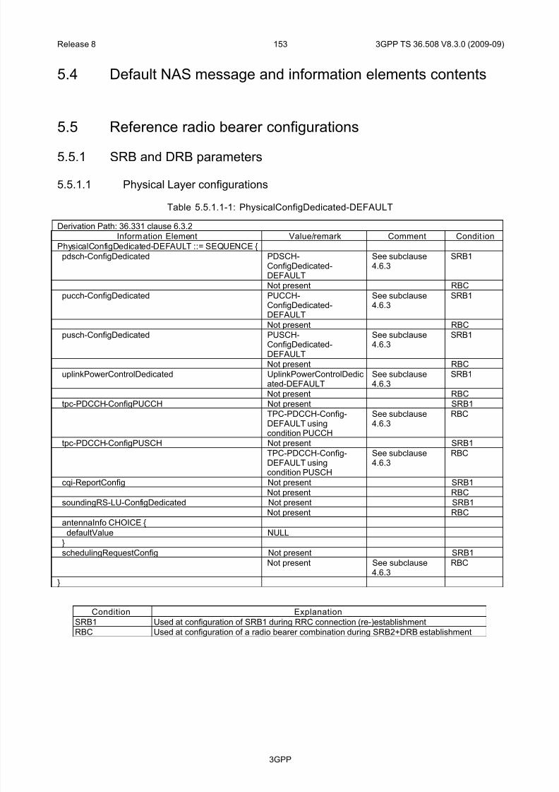
7/15/2019 Lte Sib Info
http://slidepdf.com/reader/full/lte-sib-info 153/187
3GPP
3GPP TS 36.508 V8.3.0 (2009-09)153Release 8
5.4 Default NAS message and information elements contents
5.5 Reference radio bearer configurations
5.5.1 SRB and DRB parameters
5.5.1.1 Physical Layer configurations
Table 5.5.1.1-1: PhysicalConfigDedicated-DEFAULT
Derivation Path: 36.331 clause 6.3.2
Information Element Value/remark Comment Condit ion
PhysicalConfigDedicated-DEFAULT ::= SEQUENCE {
pdsch-ConfigDedicated PDSCH-ConfigDedicated-
DEFAULT
See subclause4.6.3
SRB1
Not present RBC
pucch-ConfigDedicated PUCCH-ConfigDedicated-DEFAULT
See subclause4.6.3
SRB1
Not present RBC
pusch-ConfigDedicated PUSCH-ConfigDedicated-DEFAULT
See subclause4.6.3
SRB1
Not present RBC
uplinkPowerControlDedicated UplinkPowerControlDedicated-DEFAULT
See subclause4.6.3
SRB1
Not present RBC
tpc-PDCCH-ConfigPUCCH Not present SRB1
TPC-PDCCH-Config-DEFAULT usingcondition PUCCH
See subclause4.6.3
RBC
tpc-PDCCH-ConfigPUSCH Not present SRB1
TPC-PDCCH-Config-DEFAULT usingcondition PUSCH
See subclause4.6.3
RBC
cqi-ReportConfig Not present SRB1
Not present RBC
soundingRS-LU-ConfigDedicated Not present SRB1
Not present RBC
antennaInfo CHOICE {
defaultValue NULL
}
schedulingRequestConfig Not present SRB1Not present See subclause
4.6.3RBC
}
Condition Explanation
SRB1 Used at configuration of SRB1 during RRC connection (re-)establishment
RBC Used at configuration of a radio bearer combination during SRB2+DRB establishment
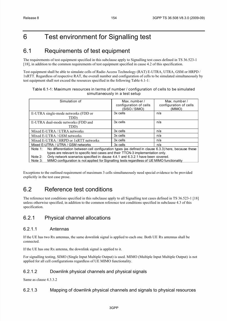
7/15/2019 Lte Sib Info
http://slidepdf.com/reader/full/lte-sib-info 154/187
3GPP
3GPP TS 36.508 V8.3.0 (2009-09)154Release 8
6 Test environment for Signalling test
6.1 Requirements of test equipment
The requirements of test equipment specified in this subclause apply to Signalling test cases defined in TS 36.523-1[18], in addition to the common requirements of test equipment specified in cause 4.2 of this specification.
Test equipment shall be able to simulate cells of Radio Access Technology (RAT) E-UTRA, UTRA, GSM or HRPD /1xRTT. Regardless of respective RAT, the overall number and configuration of cells to be simulated simultaneously bytest equipment shall not exceed the resources specified in the following Table 6.1-1:
Table 6.1-1: Maximum resources in terms of number / configuration of cells to be simulatedsimultaneously in a test setup
Simulation of Max. number /configuration of cells
(SISO / SIMO)
Max. number /configuration of cells
(MIMO)
E-UTRA single-mode networks (FDD or TDD)
3x cells n/a
E-UTRA dual-mode networks (FDD andTDD)
3x cells n/a
Mixed E-UTRA / UTRA networks 3x cells n/a
Mixed E-UTRA / GSM networks 3x cells n/a
Mixed E-UTRA / HRPD or 1xRTT networks 3x cells n/a
Mixed E-UTRA / UTRA / GSM networks 3x cells n/a
Note 1: No differentiation between cell configuration types (as defined in clause 6.3.3) here, because thesetypes are relevant to specific test cases and their TTCN-3 implementation only.
Note 2: Only network scenarios specified in clause 4.4.1 and 6.3.2.1 have been covered.Note 3: MIMO configuration is not applied for Signalling tests regardless of UE MIMO functionality
Exceptions to the outlined requirement of maximum 3 cells simultaneously need special evidence to be providedexplicitly in the test case prose.
6.2 Reference test conditions
The reference test conditions specified in this subclause apply to all Signalling test cases defined in TS 36.523-1 [18]unless otherwise specified, in addition to the common reference test conditions specified in subclause 4.3 of thisspecification.
6.2.1 Physical channel allocations
6.2.1.1 Antennas
If the UE has two Rx antennas, the same downlink signal is applied to each one. Both UE Rx antennas shall beconnected.
If the UE has one Rx antenna, the downlink signal is applied to it.
For signalling testing, SIMO (Single Input Multiple Output) is used. MIMO (Multiple Input Multiple Output) is notapplied for all cell configurations regardless of UE MIMO functionality.
6.2.1.2 Downlink physical channels and physical signals
Same as clause 4.3.3.2
6.2.1.3 Mapping of downlink physical channels and signals to physical resources
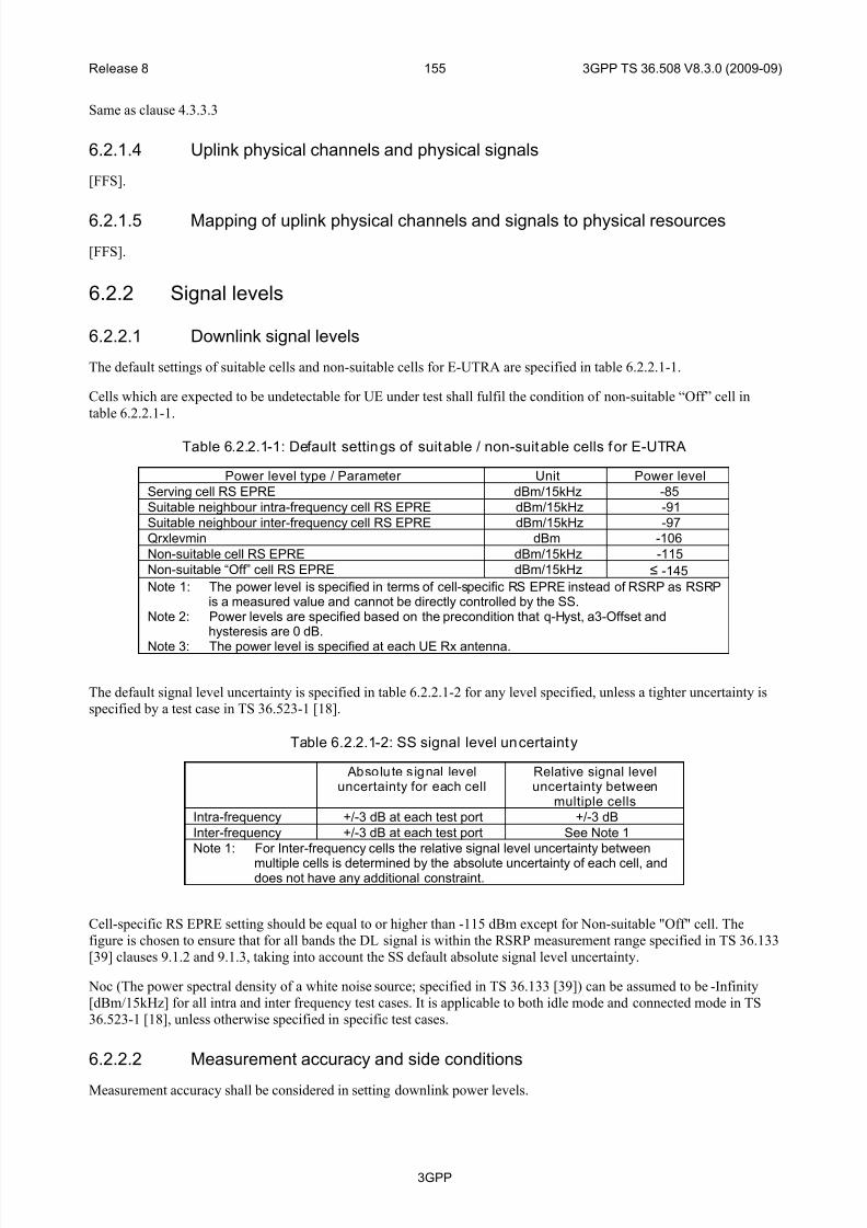
7/15/2019 Lte Sib Info
http://slidepdf.com/reader/full/lte-sib-info 155/187
3GPP
3GPP TS 36.508 V8.3.0 (2009-09)155Release 8
Same as clause 4.3.3.3
6.2.1.4 Uplink physical channels and physical signals
[FFS].
6.2.1.5 Mapping of uplink physical channels and signals to physical resources
[FFS].
6.2.2 Signal levels
6.2.2.1 Downlink signal levels
The default settings of suitable cells and non-suitable cells for E-UTRA are specified in table 6.2.2.1-1.
Cells which are expected to be undetectable for UE under test shall fulfil the condition of non-suitable “Off” cell intable 6.2.2.1-1.
Table 6.2.2.1-1: Default settings of suitable / non-suitable cells for E-UTRA
Power level type / Parameter Unit Power level
Serving cell RS EPRE dBm/15kHz -85
Suitable neighbour intra-frequency cell RS EPRE dBm/15kHz -91
Suitable neighbour inter-frequency cell RS EPRE dBm/15kHz -97
Qrxlevmin dBm -106
Non-suitable cell RS EPRE dBm/15kHz -115
Non-suitable “Off” cell RS EPRE dBm/15kHz ≤ -145
Note 1: The power level is specified in terms of cell-specific RS EPRE instead of RSRP as RSRPis a measured value and cannot be directly controlled by the SS.
Note 2: Power levels are specified based on the precondition that q-Hyst, a3-Offset andhysteresis are 0 dB.
Note 3: The power level is specified at each UE Rx antenna.
The default signal level uncertainty is specified in table 6.2.2.1-2 for any level specified, unless a tighter uncertainty isspecified by a test case in TS 36.523-1 [18].
Table 6.2.2.1-2: SS signal level uncertainty
Absolute s ignal leveluncertainty for each cell
Relative signal leveluncertainty between
multiple cells
Intra-frequency +/-3 dB at each test port +/-3 dB
Inter-frequency +/-3 dB at each test port See Note 1
Note 1: For Inter-frequency cells the relative signal level uncertainty betweenmultiple cells is determined by the absolute uncertainty of each cell, anddoes not have any additional constraint.
Cell-specific RS EPRE setting should be equal to or higher than -115 dBm except for Non-suitable "Off" cell. Thefigure is chosen to ensure that for all bands the DL signal is within the RSRP measurement range specified in TS 36.133[39] clauses 9.1.2 and 9.1.3, taking into account the SS default absolute signal level uncertainty.
Noc (The power spectral density of a white noise source; specified in TS 36.133 [39]) can be assumed to be -Infinity[dBm/15kHz] for all intra and inter frequency test cases. It is applicable to both idle mode and connected mode in TS36.523-1 [18], unless otherwise specified in specific test cases.
6.2.2.2 Measurement accuracy and side conditionsMeasurement accuracy shall be considered in setting downlink power levels.
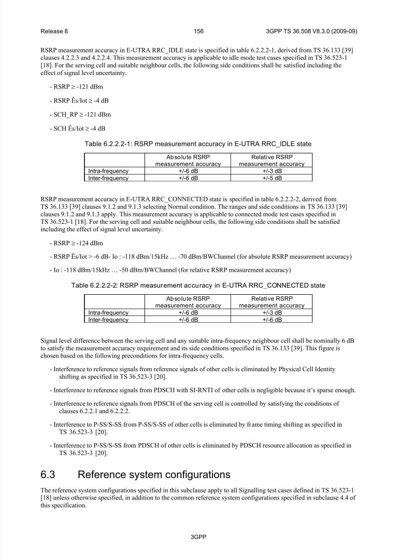
7/15/2019 Lte Sib Info
http://slidepdf.com/reader/full/lte-sib-info 156/187
3GPP
3GPP TS 36.508 V8.3.0 (2009-09)156Release 8
RSRP measurement accuracy in E-UTRA RRC_IDLE state is specified in table 6.2.2.2-1, derived from TS 36.133 [39]clauses 4.2.2.3 and 4.2.2.4. This measurement accuracy is applicable to idle mode test cases specified in TS 36.523-1[18]. For the serving cell and suitable neighbour cells, the following side conditions shall be satisfied including theeffect of signal level uncertainty.
- RSRP ≥ -121 dBm
- RSRP Ês/Iot ≥ -4 dB
- SCH_RP ≥ -121 dBm
- SCH Ês/Iot ≥ -4 dB
Table 6.2.2.2-1: RSRP measurement accuracy in E-UTRA RRC_IDLE state
Absolute RSRPmeasurement accuracy
Relative RSRPmeasurement accuracy
Intra-frequency +/-6 dB +/-3 dB
Inter-frequency +/-6 dB +/-5 dB
RSRP measurement accuracy in E-UTRA RRC_CONNECTED state is specified in table 6.2.2.2-2, derived fromTS 36.133 [39] clauses 9.1.2 and 9.1.3 selecting Normal condition. The ranges and side conditions in TS 36.133 [39]clauses 9.1.2 and 9.1.3 apply. This measurement accuracy is applicable to connected mode test cases specified inTS 36.523-1 [18]. For the serving cell and suitable neighbour cells, the following side conditions shall be satisfiedincluding the effect of signal level uncertainty.
- RSRP ≥ -124 dBm
- RSRP Ês/Iot > -6 dB- Io : -118 dBm/15kHz … -70 dBm/BWChannel (for absolute RSRP measurement accuracy)
- Io : -118 dBm/15kHz … -50 dBm/BWChannel (for relative RSRP measurement accuracy)
Table 6.2.2.2-2: RSRP measurement accuracy in E-UTRA RRC_CONNECTED state
Absolute RSRPmeasurement accuracy
Relative RSRPmeasurement accuracy
Intra-frequency +/-6 dB +/-3 dB
Inter-frequency +/-6 dB +/-6 dB
Signal level difference between the serving cell and any suitable intra-frequency neighbour cell shall be nominally 6 dBto satisfy the measurement accuracy requirement and its side conditions specified in TS 36.133 [39]. This figure ischosen based on the following preconditions for intra-frequency cells.
- Interference to reference signals from reference signals of other cells is eliminated by Physical Cell Identityshifting as specified in TS 36.523-3 [20].
- Interference to reference signals from PDSCH with SI-RNTI of other cells is negligible because it’s sparse enough.
- Interference to reference signals from PDSCH of the serving cell is controlled by satisfying the conditions of clauses 6.2.2.1 and 6.2.2.2.
- Interference to P-SS/S-SS from P-SS/S-SS of other cells is eliminated by frame timing shifting as specified inTS 36.523-3 [20].
- Interference to P-SS/S-SS from PDSCH of other cells is eliminated by PDSCH resource allocation as specified inTS 36.523-3 [20].
6.3 Reference system configurations
The reference system configurations specified in this subclause apply to all Signalling test cases defined in TS 36.523-1[18] unless otherwise specified, in addition to the common reference system configurations specified in subclause 4.4 of this specification.
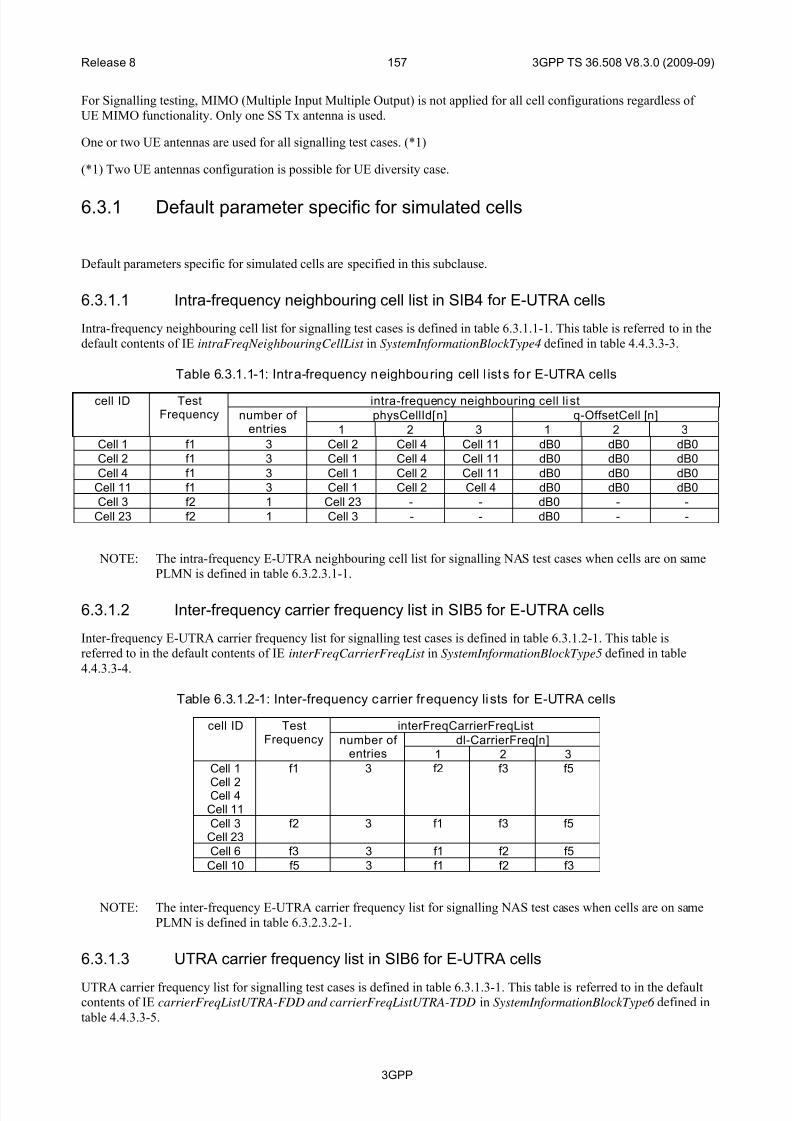
7/15/2019 Lte Sib Info
http://slidepdf.com/reader/full/lte-sib-info 157/187
3GPP
3GPP TS 36.508 V8.3.0 (2009-09)157Release 8
For Signalling testing, MIMO (Multiple Input Multiple Output) is not applied for all cell configurations regardless of UE MIMO functionality. Only one SS Tx antenna is used.
One or two UE antennas are used for all signalling test cases. (*1)
(*1) Two UE antennas configuration is possible for UE diversity case.
6.3.1 Default parameter specific for simulated cells
Default parameters specific for simulated cells are specified in this subclause.
6.3.1.1 Intra-frequency neighbouring cell list in SIB4 for E-UTRA cells
Intra-frequency neighbouring cell list for signalling test cases is defined in table 6.3.1.1-1. This table is referred to in thedefault contents of IE intraFreqNeighbouringCellList in SystemInformationBlockType4 defined in table 4.4.3.3-3.
Table 6.3.1.1-1: Intra-frequency neighbouring cell l ists for E-UTRA cells
intra-frequency neighbouring cell list
physCellId[n] q-OffsetCell [n]
cell ID TestFrequency number of
entries 1 2 3 1 2 3
Cell 1 f1 3 Cell 2 Cell 4 Cell 11 dB0 dB0 dB0
Cell 2 f1 3 Cell 1 Cell 4 Cell 11 dB0 dB0 dB0
Cell 4 f1 3 Cell 1 Cell 2 Cell 11 dB0 dB0 dB0
Cell 11 f1 3 Cell 1 Cell 2 Cell 4 dB0 dB0 dB0
Cell 3 f2 1 Cell 23 - - dB0 - -
Cell 23 f2 1 Cell 3 - - dB0 - -
NOTE: The intra-frequency E-UTRA neighbouring cell list for signalling NAS test cases when cells are on samePLMN is defined in table 6.3.2.3.1-1.
6.3.1.2 Inter-frequency carrier frequency list in SIB5 for E-UTRA cells
Inter-frequency E-UTRA carrier frequency list for signalling test cases is defined in table 6.3.1.2-1. This table isreferred to in the default contents of IE interFreqCarrierFreqList in SystemInformationBlockType5 defined in table4.4.3.3-4.
Table 6.3.1.2-1: Inter-frequency carrier frequency li sts for E-UTRA cells
interFreqCarrierFreqList
dl-CarrierFreq[n]
cell ID TestFrequency number of
entries 1 2 3
Cell 1
Cell 2Cell 4Cell 11
f1 3 f2 f3 f5
Cell 3Cell 23
f2 3 f1 f3 f5
Cell 6 f3 3 f1 f2 f5
Cell 10 f5 3 f1 f2 f3
NOTE: The inter-frequency E-UTRA carrier frequency list for signalling NAS test cases when cells are on samePLMN is defined in table 6.3.2.3.2-1.
6.3.1.3 UTRA carrier frequency list in SIB6 for E-UTRA cells
UTRA carrier frequency list for signalling test cases is defined in table 6.3.1.3-1. This table is referred to in the defaultcontents of IE carrierFreqListUTRA-FDD and carrierFreqListUTRA-TDD in SystemInformationBlockType6 defined intable 4.4.3.3-5.

7/15/2019 Lte Sib Info
http://slidepdf.com/reader/full/lte-sib-info 158/187
3GPP
3GPP TS 36.508 V8.3.0 (2009-09)158Release 8
Table 6.3.1.3-1: UTRA carrier frequency lis ts for E-UTRA cells
interFreqCarrierFreqList
carrierFreq[n]number of entries 1 2 3
3 f8 f9 f10
Table 6.3.1.3-2: Mapping of UTRA cell with TS 34.108 [5]
UTRA cel l Frequency UTRA cel l in TS34.108, clause 6.1
UTRA frequency inTS 34.108
Cell 5 f8 Cell 1 Mid
Cell 7 f8 Cell 2 Mid
Cell 8 f9 Cell 4 High
Cell 9 f10 Cell 7 Low
6.3.1.4 GERAN carrier frequency group list in SIB7 for E-UTRA cells
GERAN carrier frequency group list for signalling test cases is defined in table 6.3.1.4-1. This table is referred to in thedefault contents of IE carrierFreqsInfoList in SystemInformationBlockType7 defined in table 4.4.3.3-6.
Table 6.3.1.4-1: GERAN carrier f requency group lis t for E-UTRA cells
carrierFreqsInfoList
carrierFreqs[n]
explicitListOfARFCNs[n]
number of entries
index(n) startingARFCN[n]
number of entries ARFCN-ValueGERAN
1 f11 8 see Note
2 f12 8 see Note
3
3 f13 8 see Note
NOTE: The explicit list of ARFCNs for each cell uses the frequencies defined for the appropriate cell in the Neighbouring cells BCCH/CCCH carriers field in TS 51.010, clause 40.
Table 6.3.1.4-2: Mapping of GERAN cells with TS 51.010-1 [25]
GERAN cell Frequency GERAN cell in TS 51.010-1, clause 40
Cell 24 f11 Cell A
Cell 25 f12 Cell D
Cell 26 f13 Cell B
6.3.1.5 CDMA2000 HRPD carrier frequency list in SIB8 for E-UTRA cells
CDMA2000 HRPD carrier frequency list for signalling test cases is defined in table 6.3.1.5-1. This table is referred to inthe default contents of IE cellReselectionParametersHRPD in SystemInformationBlockTyp8 defined in table 4.4.3.3-7.
Table 6.3.1.5-1: CDMA2000 HRPD carrier frequency list for E-UTRA cells
neighCellsPerFreqList
physCellIdList[n]number of entries
index(n)
arfcn[n]
number of entries
index PhysCellIdCDMA2000
1 Cell 151 f14 2
2 Cell 16
2 f15 1 1 Cell 17
3
3 f16 1 1 Cell 18

7/15/2019 Lte Sib Info
http://slidepdf.com/reader/full/lte-sib-info 159/187
3GPP
3GPP TS 36.508 V8.3.0 (2009-09)159Release 8
6.3.1.6 CDMA2000 1xRTT carrier frequency list in SIB8 for E-UTRA cells
CDMA2000 1xRTT carrier frequency list for signalling test cases is defined in table 6.3.1.6-1. This table is referred toin the default contents of IE cellReselectionParameters1XRTT in SystemInformationBlockTyp8 defined in table 4.4.3.3-7.
Table 6.3.1.6-1: CDMA2000 1xRTT carrier frequency list for E-UTRA cells
neighCellsPerFreqList
physCellIdList[n]number of entries
index(n)
arfcn[n]
number of entries
index PhysCellIdCDMA2000
1 Cell 191 f17 2
2 Cell 20
2 f18 1 1 Cell 21
3
3 f19 1 1 Cell 22
6.3.1.7 E-UTRA carrier frequency list in SIB19 for UTRA cells
E-UTRA carrier frequency list for signalling test cases is defined in table 6.3.1.7-1. This table is referred to in thedefault contents of IE eutra-FrequencyAndPriorityInfoList in System Information Block type 19 defined in table4.4.4.1-1.
Table 6.3.1.7-1: E-UTRA carrier frequency lis t for UTRA cells
eutra-FrequencyAndPriorityInfoList
earfcn[n]number of entries 1 2 3 4 5
5 f1 f2 f3 f4 f5
6.3.2 Default configurations for NAS test casesThe default configurations specified in this subclause apply only to NAS test cases. They apply to all NAS test casesunless otherwise specified.
6.3.2.1 Simulated network scenarios for NAS test cases
Simulated network scenarios for NAS test cases to be tested are listed below.
NOTE: The number of cells specified does not necessarily correspond to the maximum number of resources to beconfigured simultaneously in test equipment. Please refer to Table 6.1-1 for such information.
- Single cell network scenario
Cell A is used.
- Single PLMN multi cell network scenario
Cell A, Cell B and Cell C are used.
- Basic Multi PLMN multi cell network scenario
Cell A and Cell G are used.
6.3.2.2 Simulated NAS cells
Simulated NAS cells and default parameters are specified in table 6.3.2.2-1.
Cell A to Cell F have the same PLMN and separate TACs.
Cell G and Cell H have:

7/15/2019 Lte Sib Info
http://slidepdf.com/reader/full/lte-sib-info 160/187
3GPP
3GPP TS 36.508 V8.3.0 (2009-09)160Release 8
- The same MCC as Cell A to Cell F
- An MNC different from Cell A to Cell F
- Separate TACs
Cell I has an MCC different from Cell A to Cell H.
Cell J has an MCC different from Cell A to Cell I.
Cell K is the same as Cell I.
Cell L has the same PLMN as Cell I, but has a different TAC.
Cell M is the same as Cell A.
Unless otherwise specified, the default parameters specified in section 4 also apply to all NAS cells.
Table 6.3.2.2-1: Default parameters for simulated NAS cells
Tracking Area GUTI (Note 2)
PLMN MME Ident ifi er
NAS cell
ID TA#MCC MNC
TAC
TA# list
(Note 1)MME Group ID MME Code
M-TMSI
Cell A TAI-1 (Note 3) 1 TAI-1 1 1
Cell B TAI-2 (Note 3) 2 TAI-2 2 1
Cell C TAI-3 (Note 3) 3 TAI-3 3 1
Cell D TAI-4 (Note 3) 4 TAI-4 4 1
Cell E TAI-5 (Note 3) 5 TAI-5 5 1
Cell F TAI-6 (Note 3) 6 TAI-6 6 1
Cell G TAI-7 (Note 4) 02 1 TAI-7 7 1
Cell H TAI-8 (Note 4) 02 2 TAI-8 8 1
Cell I TAI-9 002 101 1 TAI-9 9 1
Cell J TAI-10 003 101 1 TAI-10 10 1
Cell K TAI-9 002 101 1 TAI-9 9 1
Cell L TAI-11 002 101 2 TAI-11 11 1
Cell M TAI-1 (Note 3) 1 TAI-1 1 1
Arbitrarilyselected
according toTS 23.003
subclause 2.8[2].
NOTE 1: The value(s) in the column TA# list indicates TAI(s) included in the response messages of the registrationprocedure (ATTACH ACCEPT or TRACKING AREA UPDATE ACCEPT) when the UE performs theregistration procedure on a corresponding cell.
NOTE 2: The value in the column GUTI indicates GUTI included in the response messages of the registrationprocedure (ATTACH ACCEPT or TRACKING AREA UPDATE ACCEPT) when the UE performs theregistration procedure on a corresponding cell.
NOTE 3: Set to the same Mobile Country Code and Mobile Network Code stored in EFIMSI on the test USIM card(subclause 4.9.3).
NOTE 4: Set to the same Mobile Country Code stored in EFIMSI on the test USIM card (subclause 4.9.3).
NOTE 5: Cell A is a serving cell and the other cells are suitable neighbour cells. The definitions are specified insubclause 6.2.2.1.
Table 6.3.2.2-2: Default cell identif iers for simulated NAS cells when cells are on same PLMN
E-UTRAN Cell Identifier NAS cell ID Frequency
eNB Identifier Cell Identity
Physical layer cell identity
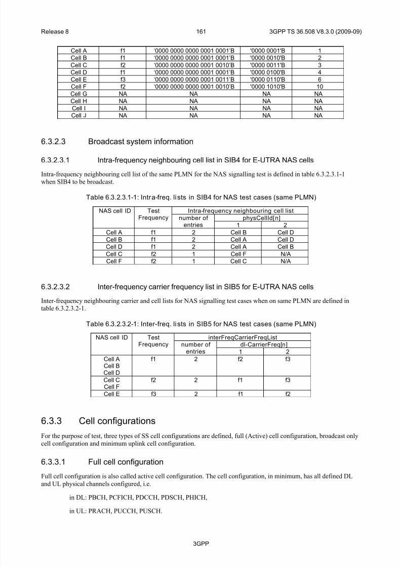
7/15/2019 Lte Sib Info
http://slidepdf.com/reader/full/lte-sib-info 161/187
3GPP
3GPP TS 36.508 V8.3.0 (2009-09)161Release 8
Cell A f1 ‘0000 0000 0000 0001 0001’B '0000 0001'B 1
Cell B f1 ‘0000 0000 0000 0001 0001’B '0000 0010'B 2
Cell C f2 ‘0000 0000 0000 0001 0010’B '0000 0011'B 3
Cell D f1 ‘0000 0000 0000 0001 0001’B '0000 0100'B 4
Cell E f3 ‘0000 0000 0000 0001 0011’B '0000 0110'B 6
Cell F f2 ‘0000 0000 0000 0001 0010’B '0000 1010'B 10
Cell G NA NA NA NA
Cell H NA NA NA NA
Cell I NA NA NA NA
Cell J NA NA NA NA
6.3.2.3 Broadcast system information
6.3.2.3.1 Intra-frequency neighbouring cell list in SIB4 for E-UTRA NAS cells
Intra-frequency neighbouring cell list of the same PLMN for the NAS signalling test is defined in table 6.3.2.3.1-1when SIB4 to be broadcast.
Table 6.3.2.3.1-1: Intra-freq. li sts in SIB4 for NAS test cases (same PLMN)
Intra-frequency neighbouring cell list
physCellId[n]
NAS cell ID TestFrequency number of
entries 1 2
Cell A f1 2 Cell B Cell D
Cell B f1 2 Cell A Cell D
Cell D f1 2 Cell A Cell B
Cell C f2 1 Cell F N/A
Cell F f2 1 Cell C N/A
6.3.2.3.2 Inter-frequency carrier frequency list in SIB5 for E-UTRA NAS cells
Inter-frequency neighbouring carrier and cell lists for NAS signalling test cases when on same PLMN are defined intable 6.3.2.3.2-1.
Table 6.3.2.3.2-1: Inter-freq. li sts in SIB5 for NAS test cases (same PLMN)
interFreqCarrierFreqListdl-CarrierFreq[n]
NAS cell ID TestFrequency number of
entries 1 2
Cell ACell BCell D
f1 2 f2 f3
Cell CCell F
f2 2 f1 f3
Cell E f3 2 f1 f2
6.3.3 Cell configurations
For the purpose of test, three types of SS cell configurations are defined, full (Active) cell configuration, broadcast onlycell configuration and minimum uplink cell configuration.
6.3.3.1 Full cell configuration
Full cell configuration is also called active cell configuration. The cell configuration, in minimum, has all defined DLand UL physical channels configured, i.e.
in DL: PBCH, PCFICH, PDCCH, PDSCH, PHICH,
in UL: PRACH, PUCCH, PUSCH.
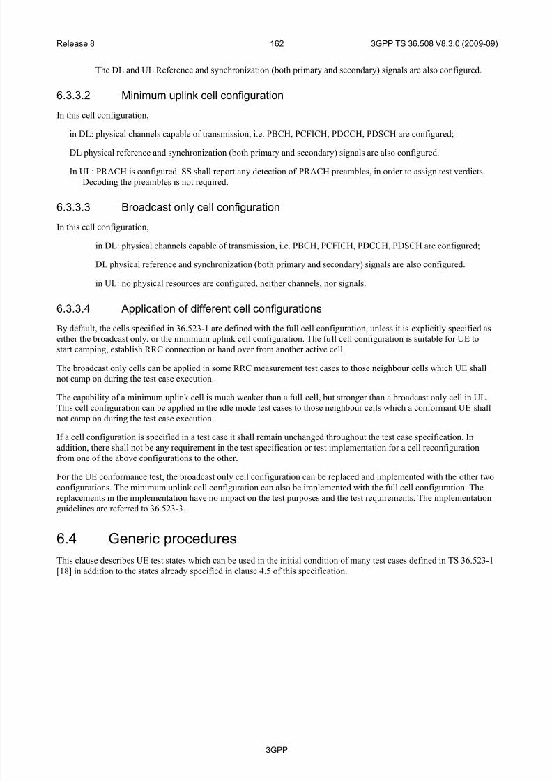
7/15/2019 Lte Sib Info
http://slidepdf.com/reader/full/lte-sib-info 162/187
3GPP
3GPP TS 36.508 V8.3.0 (2009-09)162Release 8
The DL and UL Reference and synchronization (both primary and secondary) signals are also configured.
6.3.3.2 Minimum uplink cell configuration
In this cell configuration,
in DL: physical channels capable of transmission, i.e. PBCH, PCFICH, PDCCH, PDSCH are configured;DL physical reference and synchronization (both primary and secondary) signals are also configured.
In UL: PRACH is configured. SS shall report any detection of PRACH preambles, in order to assign test verdicts.Decoding the preambles is not required.
6.3.3.3 Broadcast only cell configuration
In this cell configuration,
in DL: physical channels capable of transmission, i.e. PBCH, PCFICH, PDCCH, PDSCH are configured;
DL physical reference and synchronization (both primary and secondary) signals are also configured.
in UL: no physical resources are configured, neither channels, nor signals.
6.3.3.4 Application of different cell configurations
By default, the cells specified in 36.523-1 are defined with the full cell configuration, unless it is explicitly specified aseither the broadcast only, or the minimum uplink cell configuration. The full cell configuration is suitable for UE tostart camping, establish RRC connection or hand over from another active cell.
The broadcast only cells can be applied in some RRC measurement test cases to those neighbour cells which UE shallnot camp on during the test case execution.
The capability of a minimum uplink cell is much weaker than a full cell, but stronger than a broadcast only cell in UL.
This cell configuration can be applied in the idle mode test cases to those neighbour cells which a conformant UE shallnot camp on during the test case execution.
If a cell configuration is specified in a test case it shall remain unchanged throughout the test case specification. Inaddition, there shall not be any requirement in the test specification or test implementation for a cell reconfigurationfrom one of the above configurations to the other.
For the UE conformance test, the broadcast only cell configuration can be replaced and implemented with the other twoconfigurations. The minimum uplink cell configuration can also be implemented with the full cell configuration. Thereplacements in the implementation have no impact on the test purposes and the test requirements. The implementationguidelines are referred to 36.523-3.
6.4 Generic proceduresThis clause describes UE test states which can be used in the initial condition of many test cases defined in TS 36.523-1[18] in addition to the states already specified in clause 4.5 of this specification.

7/15/2019 Lte Sib Info
http://slidepdf.com/reader/full/lte-sib-info 163/187
3GPP
3GPP TS 36.508 V8.3.0 (2009-09)163Release 8
6.4.1 Initial UE states and setup procedures
6.4.1.1 Initial UE states and setup procedures
State 3Generic RBEstablished
State 5
Dedicated RBestablished
State 6
Loopback Activated
Figure 6.4.1.1-1: Initial UE states
In order that the UE can set up a call or session in E-UTRAN, there are a number of setup procedures to be undertakenin a hierachical sequence to move between known states. The sequences are shown in figure 6.4.1.1-1 and the status of the relevant protocols in the UE in the different states are given in table 6.4.1.1-1. State 3 is defined in clause 4.5.1.
Table 6.4.1.1-1: Protocol state for each init ial UE state
RRC ECM EMM ESM
State 5 Dedicated RBestablished
RRC_CONNECTED ECM_CONNECTED EMM-REGISTERED 1 default EPS bearer context active
N dedicated EPSbearer context(s)active
State 6 Loopback Activated RRC_CONNECTED ECM_CONNECTED EMM-REGISTERED 1 default EPS bearer context activeN dedicated EPSbearer context(s)active
6.4.1.2 Dedicated Bearer Establishment (to state 5)
6.4.1.2.1 Initial conditionsSystem Simulator:
- Parameters are set to the default parameters for the basic single cell environment, as defined in subclause 4.4, unlessotherwise specified in the test case.
User Equipment:
- The UE shall be in Generic RB established (State 3).
6.4.1.2.2 Definition of system information messages
The default system information messages are used.
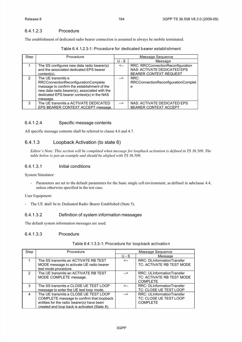
7/15/2019 Lte Sib Info
http://slidepdf.com/reader/full/lte-sib-info 164/187
3GPP
3GPP TS 36.508 V8.3.0 (2009-09)164Release 8
6.4.1.2.3 Procedure
The establishment of dedicated radio bearer connection is assumed to always be mobile terminated.
Table 6.4.1.2.3-1: Procedure for dedicated bearer establ ishment
Step Procedure Message Sequence
U - S Message
1 The SS configures new data radio bearer(s)and the associated dedicated EPS bearer context(s).
<-- RRC: RRCConnectionReconfigurationNAS: ACTIVATE DEDICATED EPSBEARER CONTEXT REQUEST
2 The UE transmits aRRCConnectionReconfigurationCompletemessage to confirm the establishment of thenew data radio bearer(s), associated with thededicated EPS bearer context(s) in the NASmessage.
--> RRC:RRCConnectionReconfigurationComplete
3 The UE transmits a ACTIVATE DEDICATEDEPS BEARER CONTEXT ACCEPT message.
--> NAS: ACTIVATE DEDICATED EPSBEARER CONTEXT ACCEPT
6.4.1.2.4 Specific message contents
All specific message contents shall be referred to clause 4.6 and 4.7.
6.4.1.3 Loopback Activation (to state 6)
Editor’s Note: This section will be completed when message for loopback activation is defined in TS 36.509. The
table below is just an example and should be alighed with TS 36.509.
6.4.1.3.1 Initial conditions
System Simulator:
- Parameters are set to the default parameters for the basic single cell environment, as defined in subclause 4.4,unless otherwise specified in the test case.
User Equipment:
- The UE shall be in Dedicated Radio Bearer Established (State 5).
6.4.1.3.2 Definition of system information messages
The default system information messages are used.
6.4.1.3.3 Procedure
Table 6.4.1.3.3-1: Procedure for loopback act ivation
Step Procedure Message Sequence
U - S Message
1 The SS transmits an ACTIVATE RB TESTMODE message to activate UE radio bearer test mode procedure.
<-- RRC: DLInformationTransfer TC: ACTIVATE RB TEST MODE
2 The UE transmits an ACTIVATE RB TESTMODE COMPLETE message.
--> RRC: ULInformationTransfer TC: ACTIVATE RB TEST MODECOMPLETE
3 The SS transmits a CLOSE UE TEST LOOPmessage to enter the UE test loop mode.
<-- RRC: DLInformationTransfer TC: CLOSE UE TEST LOOP
4 The UE transmits a CLOSE UE TEST LOOP
COMPLETE message to confirm that loopbackentities for the radio bearer(s) have beencreated and loop back is activated (State 6).
--> RRC: ULInformationTransfer
TC: CLOSE UE TEST LOOPCOMPLETE
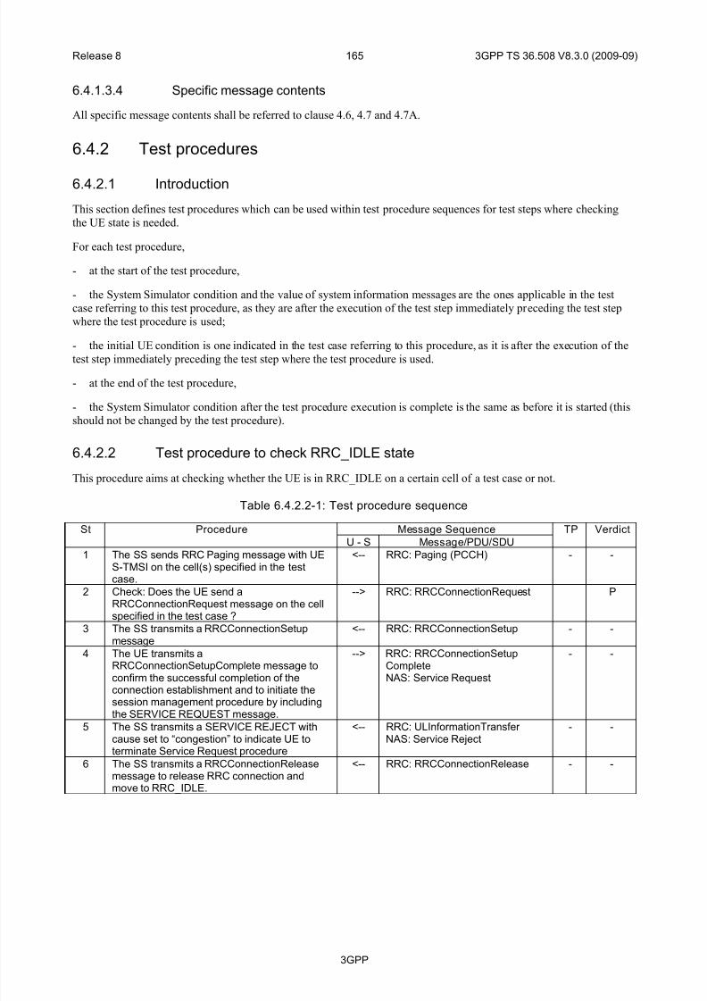
7/15/2019 Lte Sib Info
http://slidepdf.com/reader/full/lte-sib-info 165/187
3GPP
3GPP TS 36.508 V8.3.0 (2009-09)165Release 8
6.4.1.3.4 Specific message contents
All specific message contents shall be referred to clause 4.6, 4.7 and 4.7A.
6.4.2 Test procedures
6.4.2.1 Introduction
This section defines test procedures which can be used within test procedure sequences for test steps where checkingthe UE state is needed.
For each test procedure,
- at the start of the test procedure,
- the System Simulator condition and the value of system information messages are the ones applicable in the testcase referring to this test procedure, as they are after the execution of the test step immediately preceding the test stepwhere the test procedure is used;
- the initial UE condition is one indicated in the test case referring to this procedure, as it is after the execution of thetest step immediately preceding the test step where the test procedure is used.
- at the end of the test procedure,
- the System Simulator condition after the test procedure execution is complete is the same as before it is started (thisshould not be changed by the test procedure).
6.4.2.2 Test procedure to check RRC_IDLE state
This procedure aims at checking whether the UE is in RRC_IDLE on a certain cell of a test case or not.
Table 6.4.2.2-1: Test procedure sequence
St Procedure Message Sequence TP Verdict
U - S Message/PDU/SDU
1 The SS sends RRC Paging message with UES-TMSI on the cell(s) specified in the testcase.
<-- RRC: Paging (PCCH) - -
2 Check: Does the UE send aRRCConnectionRequest message on the cellspecified in the test case ?
--> RRC: RRCConnectionRequest P
3 The SS transmits a RRCConnectionSetup message
<-- RRC: RRCConnectionSetup - -
4 The UE transmits aRRCConnectionSetupComplete message toconfirm the successful completion of theconnection establishment and to initiate thesession management procedure by includingthe SERVICE REQUEST message.
--> RRC: RRCConnectionSetupComplete NAS: Service Request
- -
5 The SS transmits a SERVICE REJECT withcause set to “congestion” to indicate UE toterminate Service Request procedure
<-- RRC: ULInformationTransfer NAS: Service Reject
- -
6 The SS transmits a RRCConnectionRelease message to release RRC connection andmove to RRC_IDLE.
<-- RRC: RRCConnectionRelease - -

7/15/2019 Lte Sib Info
http://slidepdf.com/reader/full/lte-sib-info 166/187
3GPP
3GPP TS 36.508 V8.3.0 (2009-09)166Release 8
6.4.2.3 Test procedure to check RRC_CONNECTED state
Table 6.4.2.3-1: Test procedure sequence
St Procedure Message Sequence TP VerdictU - S Message/PDU/SDU
1 The SS sends UECapabilityEnquiry messageto the UE. <-- UECapabilityEnquiry - -
2 Check: Does the UE send aUECapabilityInformation message?
--> UECapabilityInformation P
6.4.2.4 Test procedure Paging (for NAS testing)
This procedure aims at checking whether the UE is in registered with a certain S-TMSI.
This procedure is identical to the procedure in 6.4.2.2 except that the S-TMSI as indicated in step 1 is the one explicitlyspecified in the test step calling this procedure.
6.4.2.5 Test procedure for no response to paging (for NAS testing)
This procedure aims at checking that the UE ignores paging messages with a specified identity.
The procedure is defined in table 6.4.2.5-1.
Table 6.4.2.5-1: Test procedure sequence
St Procedure Message Sequence TP Verdict
U - S Message
1 The SS transmits a paging message using theUE identity and the CN domain which are bothspecified in the referring test step, and on thecell which is specified in the referring test step.
<-- Paging - -
2 Check: Does the UE send aRRCConnectionRequest message on the cellwhere the paging was transmitted within thenext 3s?
--> RRCConnectionRequest F
6.4.2.6 Test procedure to check that a dedicated EPS bearer context is active (for NAS testing)
This procedure aims at checking that a dedicated EPS bearer context is active.
The procedure is defined in table 6.4.2.6-1.
Table 6.4.2.6-1: Test procedure sequence
St Procedure Message Sequence TP Verdict
U - S Message
1 The SS modifies existing data radio bearer(s)and the associated EPS bearer context(s) withBearer QoS update.
<-- RRC:RRCConnectionReconfigurationNAS: MODIFY EPS BEARERCONTEXT REQUEST
- -
2 The UE transmits aRRCConnectionReconfigurationCompletemessage to confirm the modification of theexisting data radio bearer(s), associated withthe EPS bearer context(s) in the NASmessage.
--> RRC:RRCConnectionReconfigurationComplete
- -
3 Check: Does the UE transmit a MODIFY EPSBEARER CONTEXT ACCEPT message?
--> RRC: ULInformationTransfer NAS: MODIFY EPS BEARERCONTEXT ACCEPT
P

7/15/2019 Lte Sib Info
http://slidepdf.com/reader/full/lte-sib-info 167/187
3GPP
3GPP TS 36.508 V8.3.0 (2009-09)167Release 8
6.4.2.7 Test procedure to check that UE is camped on a new E-UTRAN cell
This procedure aims at checking whether the UE is camping on a new E-UTRAN cell with different TAI of a test caseor not.
The procedure is defined in table 6.4.2.7-1.
Table 6.4.2.7-1: Test procedure sequence
St Procedure Message Sequence TP Verdict
U - S Message
1 Check: Does the UE send aRRCConnectionRequest message on the cellspecified in the test case?
--> RRC: RRCConnectionRequest - P
2 SS transmit an RRCConnectionSetup message.
<--RRC: RRCConnectionSetup - -
3 The UE transmits aRRCConnectionSetupComplete message toconfirm the successful completion of theconnection establishment and a TRACKING AREA UPDATE REQUEST message is sent toupdate the registration of the actual trackingarea.
--> RRC:RRCConnectionSetupComplete NAS: TRACKING AREA UPDATEREQUEST
- -
4 SS responds with TRACKING AREA UPDATE ACCEPT message.
<-- RRC: DLInformationTransfer NAS: TRACKING AREA UPDATE ACCEPT
- -
5 The UE transmits a TRACKING AREAUPDATE COMPLETE
--> RRC: ULInformationTransfer NAS: TRACKING AREA UPDATECOMPLETE
- -
6 The SS transmits an RRCConnectionRelease message to release RRC connection andmove to RRC_IDLE.
<-- RRC: RRCConnectionRelease - -
NOTE 1: The periodic tracking area updating timer T3412 is deactivated by default during the attach procedure (TS36.508 clause 4.7.2).
NOTE 2: The SS does not initiate authentication and NAS SECURITY MODE COMMAND are not performed(reuse of keys allocated during the attach procedure).
6.4.2.8 Test procedure to check that UE is camped on a new UTRAN cell
This procedure aims at checking whether the UE is camping on a new UTRAN cell of a test case or not.
The procedure is defined in table 6.4.2.8-1.
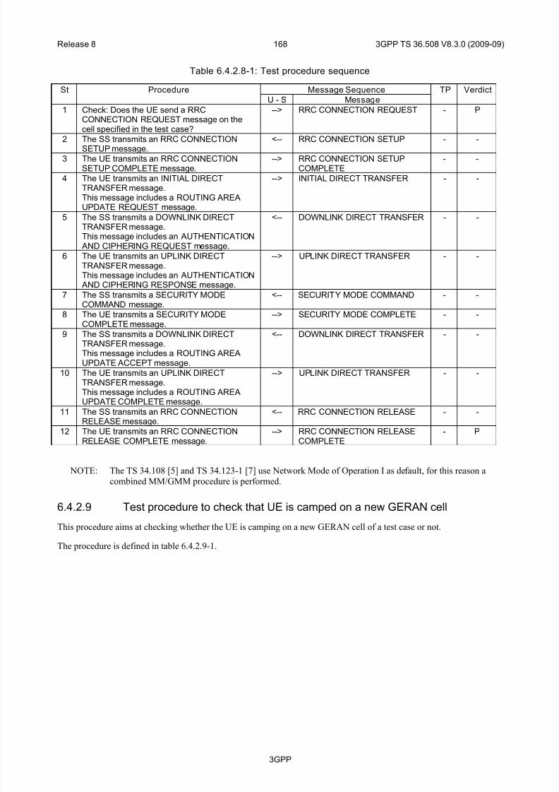
7/15/2019 Lte Sib Info
http://slidepdf.com/reader/full/lte-sib-info 168/187
3GPP
3GPP TS 36.508 V8.3.0 (2009-09)168Release 8
Table 6.4.2.8-1: Test procedure sequence
St Procedure Message Sequence TP Verdict
U - S Message
1 Check: Does the UE send a RRCCONNECTION REQUEST message on thecell specified in the test case?
--> RRC CONNECTION REQUEST - P
2 The SS transmits an RRC CONNECTIONSETUP message.
<-- RRC CONNECTION SETUP - -
3 The UE transmits an RRC CONNECTIONSETUP COMPLETE message.
--> RRC CONNECTION SETUPCOMPLETE
- -
4 The UE transmits an INITIAL DIRECTTRANSFER message.This message includes a ROUTING AREAUPDATE REQUEST message.
--> INITIAL DIRECT TRANSFER - -
5 The SS transmits a DOWNLINK DIRECTTRANSFER message.This message includes an AUTHENTICATION AND CIPHERING REQUEST message.
<-- DOWNLINK DIRECT TRANSFER - -
6 The UE transmits an UPLINK DIRECTTRANSFER message.
This message includes an AUTHENTICATION AND CIPHERING RESPONSE message.
--> UPLINK DIRECT TRANSFER - -
7 The SS transmits a SECURITY MODECOMMAND message.
<-- SECURITY MODE COMMAND - -
8 The UE transmits a SECURITY MODECOMPLETE message.
--> SECURITY MODE COMPLETE - -
9 The SS transmits a DOWNLINK DIRECTTRANSFER message.This message includes a ROUTING AREAUPDATE ACCEPT message.
<-- DOWNLINK DIRECT TRANSFER - -
10 The UE transmits an UPLINK DIRECTTRANSFER message.This message includes a ROUTING AREAUPDATE COMPLETE message.
--> UPLINK DIRECT TRANSFER - -
11 The SS transmits an RRC CONNECTIONRELEASE message.
<-- RRC CONNECTION RELEASE - -
12 The UE transmits an RRC CONNECTIONRELEASE COMPLETE message.
--> RRC CONNECTION RELEASECOMPLETE
- P
NOTE: The TS 34.108 [5] and TS 34.123-1 [7] use Network Mode of Operation I as default, for this reason acombined MM/GMM procedure is performed.
6.4.2.9 Test procedure to check that UE is camped on a new GERAN cell
This procedure aims at checking whether the UE is camping on a new GERAN cell of a test case or not.
The procedure is defined in table 6.4.2.9-1.
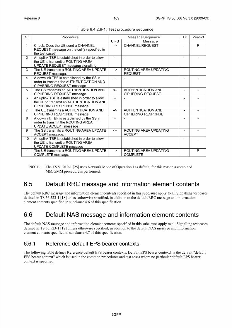
7/15/2019 Lte Sib Info
http://slidepdf.com/reader/full/lte-sib-info 169/187
3GPP
3GPP TS 36.508 V8.3.0 (2009-09)169Release 8
Table 6.4.2.9-1: Test procedure sequence
St Procedure Message Sequence TP Verdict
U - S Message
1 Check: Does the UE send a CHANNELREQUEST message on the cell(s) specified inthe test case?
--> CHANNEL REQUEST - P
2 An uplink TBF is established in order to allowthe UE to transmit a ROUTING AREAUPDATE REQUEST message signalling.
- - - -
3 The UE transmits a ROUTING AREA UPDATEREQUEST message.
--> ROUTING AREA UPDATINGREQUEST
- -
4 A downlink TBF is established by the SS inorder to transmit the AUTHENTICATION ANDCIPHERING REQUEST message
- - - -
5 The SS transmits an AUTHENTICATION ANDCIPHERING REQUEST message.
<-- AUTHENTICATION ANDCIPHERING REQUEST
- -
6 An uplink TBF is established in order to allowthe UE to transmit an AUTHENTICATION ANDCIPHERING RESPONSE message
- - - -
7 The UE transmits a AUTHENTICATION AND
CIPHERING RESPONSE message.
--> AUTHENTICATION AND
CIPHERING RESPONSE
- -
8 A downlink TBF is established by the SS inorder to transmit the ROUTING AREAUPDATE ACCEPT message
- - - -
9 The SS transmits a ROUTING AREA UPDATE ACCEPT message.
<-- ROUTING AREA UPDATING ACCEPT
- -
10 An uplink TBF is established in order to allowthe UE to transmit a ROUTING AREAUPDATE COMPLETE message
- -
11 The UE transmits a ROUTING AREA UPDATECOMPLETE message.
--> ROUTING AREA UPDATINGCOMPLETE
- P
NOTE: The TS 51.010-1 [25] uses Network Mode of Operation I as default, for this reason a combined
MM/GMM procedure is performed.
6.5 Default RRC message and information element contents
The default RRC message and information element contents specified in this subclause apply to all Signalling test casesdefined in TS 36.523-1 [18] unless otherwise specified, in addition to the default RRC message and informationelement contents specified in subclause 4.6 of this specification.
6.6 Default NAS message and information element contents
The default NAS message and information element contents specified in this subclause apply to all Signalling test cases
defined in TS 36.523-1 [18] unless otherwise specified, in addition to the default NAS message and informationelement contents specified in subclause 4.7 of this specification.
6.6.1 Reference default EPS bearer contexts
The following table defines Reference default EPS bearer contexts. Default EPS bearer context1 is the default "defaultEPS bearer context" which is used in the common procedures and test cases where no particular default EPS bearer context is specified.
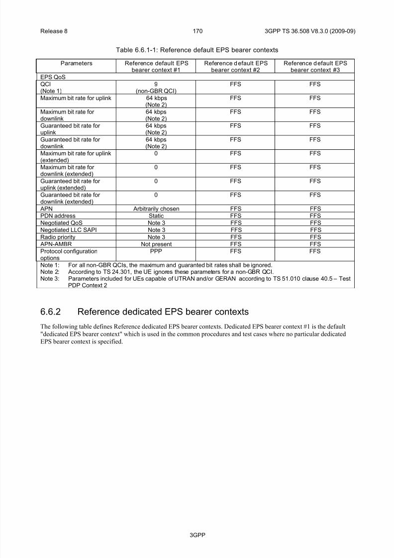
7/15/2019 Lte Sib Info
http://slidepdf.com/reader/full/lte-sib-info 170/187
3GPP
3GPP TS 36.508 V8.3.0 (2009-09)170Release 8
Table 6.6.1-1: Reference default EPS bearer contexts
Parameters Reference default EPSbearer context #1
Reference defaul t EPSbearer context #2
Reference defaul t EPSbearer context #3
EPS QoS
QCI(Note 1)
9(non-GBR QCI)
FFS FFS
Maximum bit rate for uplink 64 kbps(Note 2)
FFS FFS
Maximum bit rate for downlink
64 kbps(Note 2)
FFS FFS
Guaranteed bit rate for uplink
64 kbps(Note 2)
FFS FFS
Guaranteed bit rate for downlink
64 kbps(Note 2)
FFS FFS
Maximum bit rate for uplink(extended)
0 FFS FFS
Maximum bit rate for downlink (extended)
0 FFS FFS
Guaranteed bit rate for uplink (extended)
0 FFS FFS
Guaranteed bit rate for downlink (extended)
0 FFS FFS
APN Arbitrarily chosen FFS FFS
PDN address Static FFS FFS
Negotiated QoS Note 3 FFS FFS
Negotiated LLC SAPI Note 3 FFS FFS
Radio priority Note 3 FFS FFS
APN-AMBR Not present FFS FFS
Protocol configurationoptions
PPP FFS FFS
Note 1: For all non-GBR QCIs, the maximum and guaranted bit rates shall be ignored.Note 2: According to TS 24.301, the UE ignores these parameters for a non-GBR QCI.Note 3: Parameters included for UEs capable of UTRAN and/or GERAN according to TS 51.010 clause 40.5 – Test
PDP Context 2
6.6.2 Reference dedicated EPS bearer contexts
The following table defines Reference dedicated EPS bearer contexts. Dedicated EPS bearer context #1 is the default"dedicated EPS bearer context" which is used in the common procedures and test cases where no particular dedicatedEPS bearer context is specified.

7/15/2019 Lte Sib Info
http://slidepdf.com/reader/full/lte-sib-info 171/187
3GPP
3GPP TS 36.508 V8.3.0 (2009-09)171Release 8
Table 6.6.2-1: Reference dedicated EPS bearer contexts
Parameters Reference dedicated EPSbearer context #1
Reference dedicated EPSbearer context #2
Reference dedicated EPSbearer context #3
Linked EPS bearer identity Reference default EPSbearer #1
Reference default EPSbearer #1
FFS
EPS QoS
QCI(Note 1)
4(GBR QCI)
5(non-GBR QCI)
FFS
Maximum bit rate for uplink 384 kbps 384 kbps(Note 2)
FFS
Maximum bit rate for downlink
384 kbps 384 kbps(Note 2)
FFS
Guaranteed bit rate for uplink
128 kbps 128 kbps(Note 2)
FFS
Guaranteed bit rate for downlink
128 kbps 128 kbps(Note 2)
FFS
Maximum bit rate for uplink(extended)
0 0 FFS
Maximum bit rate for downlink (extended)
0 0 FFS
Guaranteed bit rate for uplink (extended)
0 0 FFS
Guaranteed bit rate for downlink (extended)
0 0 FFS
TFT
TFT operation code "create new TFT" "create new TFT" FFS
E bit 0 0 FFS
Number of packet filters 0(Note 4)
1 FFS
Packet filter identifier 1 N/A 1 FFS
Packet filter evaluationprecedence 1
N/A 0 FFS
Packet filter contents 1 N/A - IPv4 or IPv6 sourceaddress type: fixed
- Protocol identifier - Destination port rangetype: *- Source port range type: *
FFS
Negotiated QoS Note 3 Note 3 FFS
Negotiated LLC SAPI Note 3 Note 3 FFS
Radio priority Note 3 Note 3 FFS
Protocol configurationoptions
PPP PPP FFS
Note 1: For all non-GBR QCIs, the maximum and guaranted bit rates shall be ignored.Note 2: According to TS 24.301, the UE ignores these parameters for a non-GBR QCI.Note 3: Parameters included for UEs capable of UTRAN and/or GERAN according to TBD (TS 51.010 clause 40.5
has no Test PDP Contexts for conversational traffic class)Note 4: It may be necessary to provide packet filters for GBR QCI bearers (FFS).
6.7 Timer Tolerances
The timer tolerances specified in this subclause apply to all Signalling test cases defined in TS 36.523-1 [18] unlessotherwise specified
All the timers used during testing are within a tolerance margin given by the equation below. If for a specific test adifferent tolerance value is required then this should be specified in the relevant test document (i.e. the document wherethe test is described).
Timer tolerance = 10%, or 5 × RTT , whichever value is the greater.
Where RTT = 8 TTIs for FDD, and RTT= Maximum RTT from Table 6.7-1 for TDD (see Note).
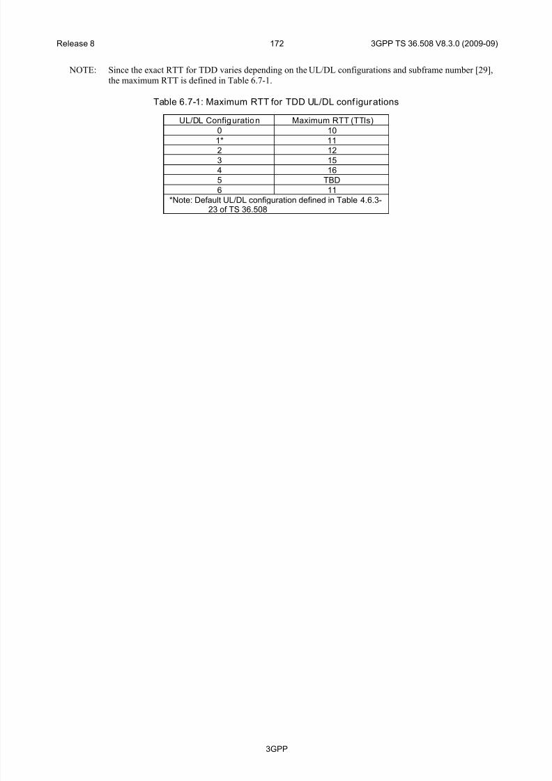
7/15/2019 Lte Sib Info
http://slidepdf.com/reader/full/lte-sib-info 172/187
3GPP
3GPP TS 36.508 V8.3.0 (2009-09)172Release 8
NOTE: Since the exact RTT for TDD varies depending on the UL/DL configurations and subframe number [29],the maximum RTT is defined in Table 6.7-1.
Table 6.7-1: Maximum RTT for TDD UL/DL conf igurations
UL/DL Configuration Maximum RTT (TTIs)
0 10
1* 112 12
3 15
4 16
5 TBD
6 11
*Note: Default UL/DL configuration defined in Table 4.6.3-23 of TS 36.508

7/15/2019 Lte Sib Info
http://slidepdf.com/reader/full/lte-sib-info 173/187
3GPP
3GPP TS 36.508 V8.3.0 (2009-09)173Release 8
Annex A (informative):Connection Diagrams
Definition of Terms
System Simulator or SS – A device or system, that is capable of generating simulated Node B signalling and analysingUE signalling responses on one or more RF channels, in order to create the required test environment for the UE under test. It will also include the following capabilities:
1. Measurement and control of the UE Tx output power through TPC commands
2. Measurement of Throughput
3. Measurement of signalling timing and delays
4. Ability to simulate UTRAN and/or E-UTRAN and/or GERAN signalling
Test System – A combination of devices brought together into a system for the purpose of making one or moremeasurements on a UE in accordance with the test case requirements. A test system may include one or more SystemSimulators if additional signalling is required for the test case. The following diagrams are all examples of Test Systems.
NOTE: The above terms are logical definitions to be used to describe the test methods used in the documentsTS36.521-1 , TS 36.523-1and TS36.521-3 in practice, real devices called 'System Simulators' may alsoinclude additional measurement capabilities or may only support those features required for the test casesthey are designed to perform.
NOTE: Components in the connection diagrams:The components in the connection diagrams represent ideal components. They are intended to display thewanted signal flow. They don’t mandate real implementations. An alternative to Fig. A3 is shown belowas an example: It is nearer to real implementations. The signal levels are the same as in Fig A3. Thesignal flow cannot be displayed as detailled as in Fig A.3.
SS
RX/TX
RX
UE under Test
RX/TX
Ior
Îor Splitter/combiner
Al ternative to Fig A.3
Connetion: Each connection is displayed as a one or two sided arrow, showing the intended signal flow.
Circulator: The singal, entering one port, is conducted to the adjacent port, indicated by the arrow. The attenuationamong the above mentioned ports is ideally 0 and the isolation among the other ports is ideally ∞.
Splitter: a spliter has one input and 2 or more outputs. The signal at the input is equally divided to the outputs. The
attenuation from input to the outputs is ideally 0 and the isolation between the outputs is ideally∞
.Combiner: a combiner has one output and 2 or more inputs. The signals at the inputs are conducted to the output, allwith the same, ideally 0 attentuation. The isolation between the inputs is ideally∞.
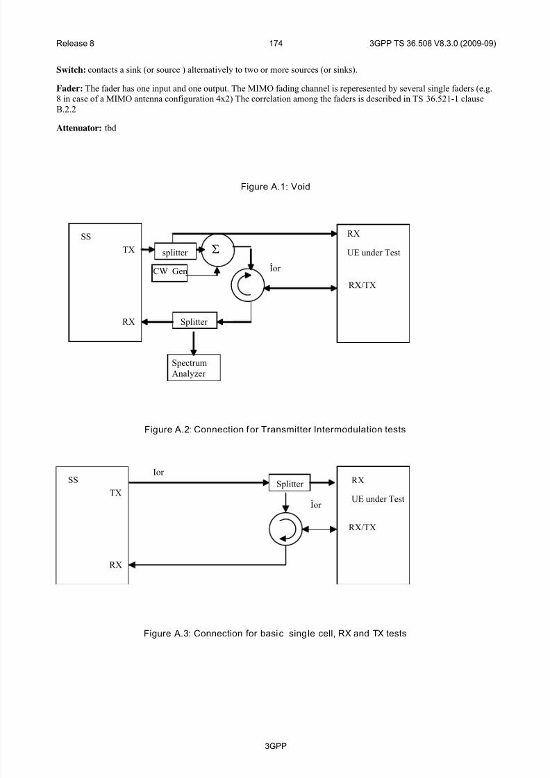
7/15/2019 Lte Sib Info
http://slidepdf.com/reader/full/lte-sib-info 174/187
3GPP
3GPP TS 36.508 V8.3.0 (2009-09)174Release 8
Switch: contacts a sink (or source ) alternatively to two or more sources (or sinks).
Fader: The fader has one input and one output. The MIMO fading channel is reperesented by several single faders (e.g.8 in case of a MIMO antenna configuration 4x2) The correlation among the faders is described in TS 36.521-1 clauseB.2.2
Attenuator: tbd
Figure A.1: Void
SS
TX
RX
Îor
SpectrumAnalyzer
RX
UE under Test
RX/TX
Splitter
CW Gen
Σ splitter
Figure A.2: Connection for Transmitter Intermodulation tests
SS
TX
RX
RX
UE under Test
RX/TX
Ior
Îor
Splitter
Figure A.3: Connection for basic sing le cell, RX and TX tests
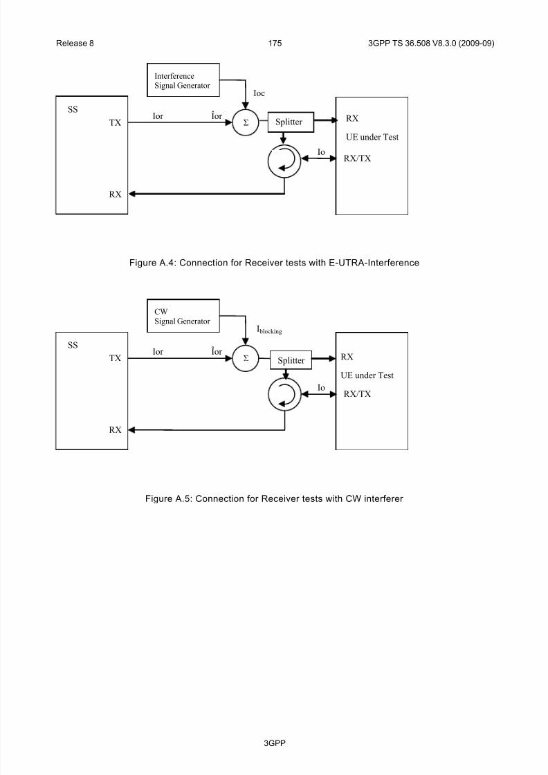
7/15/2019 Lte Sib Info
http://slidepdf.com/reader/full/lte-sib-info 175/187
3GPP
3GPP TS 36.508 V8.3.0 (2009-09)175Release 8
RX
UE under Test
SS
TX
RX
RX/TX
Ior
Io
Σ
Interference Signal Generator
Ioc
Îor Splitter
Figure A.4: Connection for Receiver tests with E-UTRA-Interference
RX
UE under Test
SS
TX
RX
RX/TX
Ior
Io
Σ
CWSignal Generator
I blocking
Îor Splitter
Figure A.5: Connection for Receiver tests with CW interferer
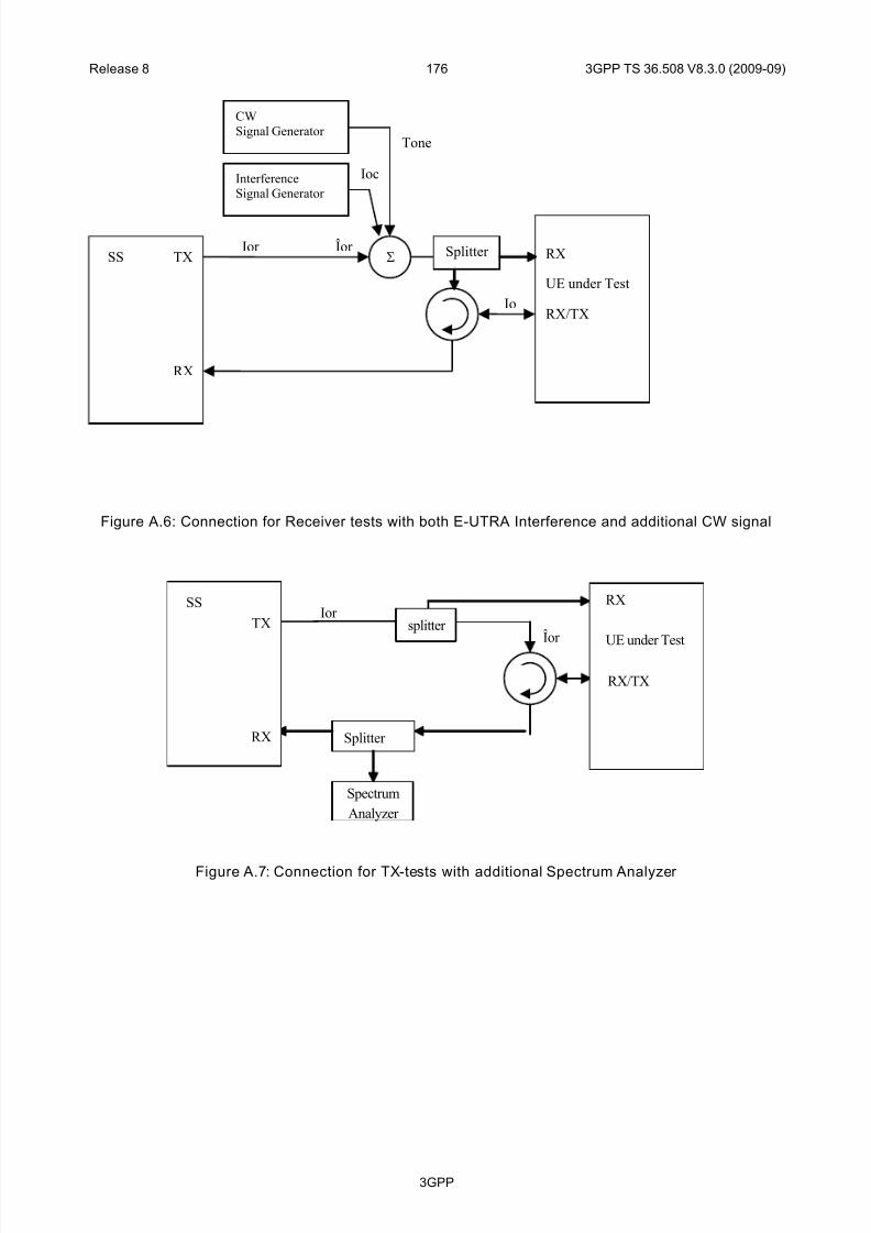
7/15/2019 Lte Sib Info
http://slidepdf.com/reader/full/lte-sib-info 176/187
3GPP
3GPP TS 36.508 V8.3.0 (2009-09)176Release 8
RX
UE under Test
SS TX
RX
Ior
Io
Σ
Tone
Îor
CW Signal Generator
IocInterference Signal Generator
RX/TX
Splitter
Figure A.6: Connection for Receiver tests with both E-UTRA Interference and additional CW signal
Splitter
Spectrum
Analyzer
splitter
SS
TX
RX
Ior
Îor
RX
UE under Test
RX/TX
Figure A.7: Connection for TX-tests with additional Spectrum Analyzer
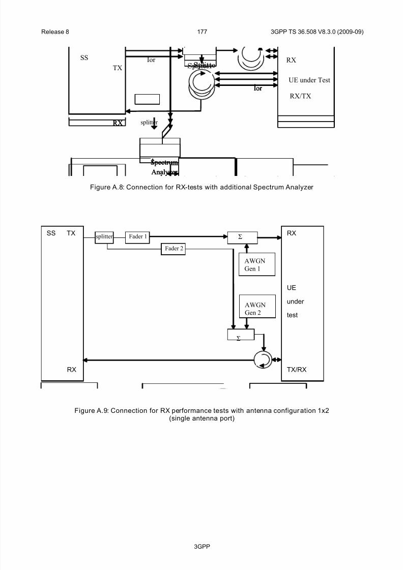
7/15/2019 Lte Sib Info
http://slidepdf.com/reader/full/lte-sib-info 177/187
3GPP
3GPP TS 36.508 V8.3.0 (2009-09)177Release 8
Spectrum
Analyzer
Splitte
Îor
SS
TX
RX
RX
UE under Test
RX/TX
Spectrum
Analyzer
Splitte
Îor
SS
TX
RX
Ior RX
UE under Test
RX/TX
Spectrum
Analyzer
Splitter
Îor
SS
TX
RX
RX
UE under Test
RX/TX
splitter
Figure A.8: Connection for RX-tests with additional Spectrum Analyzer
SS TX
RX
RX
UE
under
test
TX/RX
Fader 1
Fader 2
Σ
Σ
splitter
AWGNGen 1
AWGNGen 2
Figure A.9: Connection for RX performance tests with antenna configuration 1x2(single antenna port)
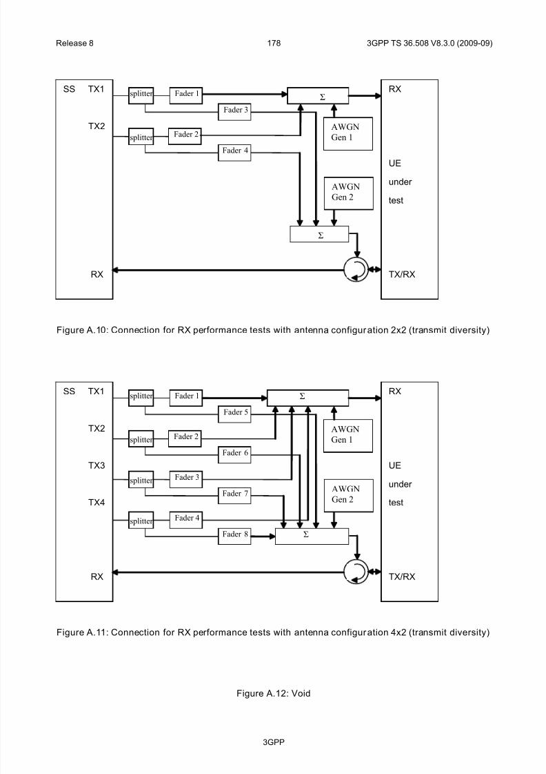
7/15/2019 Lte Sib Info
http://slidepdf.com/reader/full/lte-sib-info 178/187
3GPP
3GPP TS 36.508 V8.3.0 (2009-09)178Release 8
SS TX1
TX2
RX
RX
UE
under
test
TX/RX
Fader 1
Fader 3
Fader 4
Σ
Σ
splitter
splitter
AWGN
Gen 1
AWGNGen 2
Fader 2
Figure A.10: Connection for RX performance tests with antenna configuration 2x2 (transmit diversity)
SS TX1
TX2
TX3
TX4
RX
RX
UE
under
test
TX/RX
Fader 1
Fader 3
Fader 4
Fader 5
Fader 8
Fader 7
Fader 6
Σ
Σ
splitter
splitter
splitter
splitter
AWGNGen 1
AWGNGen 2
Fader 2
Figure A.11: Connection for RX performance tests with antenna configuration 4x2 (transmit diversity)
Figure A.12: Void

7/15/2019 Lte Sib Info
http://slidepdf.com/reader/full/lte-sib-info 179/187
3GPP
3GPP TS 36.508 V8.3.0 (2009-09)179Release 8
Figure A.13: Void
SS1 TX
RX
RX
UEunder
test
TX/RX
Σ
Σ
splitter
AWGNGen 1
AWGNGen 2
SS2 TX
RX
splitter
splitter
Figure A.14: Connection for 2 cells with static propagation and receive diversity
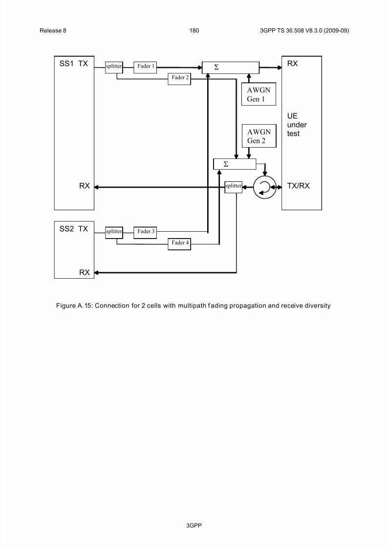
7/15/2019 Lte Sib Info
http://slidepdf.com/reader/full/lte-sib-info 180/187
3GPP
3GPP TS 36.508 V8.3.0 (2009-09)180Release 8
SS1 TX
RX
RX
UEunder test
TX/RX
Fader 1
Fader 2
Σ
Σ
splitter
AWGNGen 1
AWGNGen 2
SS2 TX
RX
Fader 3
Fader 4
splitter
splitter
Figure A.15: Connection for 2 cells with multipath fading propagation and receive diversity
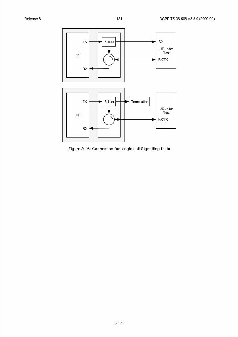
7/15/2019 Lte Sib Info
http://slidepdf.com/reader/full/lte-sib-info 181/187
3GPP
3GPP TS 36.508 V8.3.0 (2009-09)181Release 8
SS
UE under
Test
RX/TX
RXTX
RX
Splitter
SS
UE under
Test
RX/TX
TX
RX
Splitter Termination
Figure A.16: Connection for s ingle cell Signalling tests
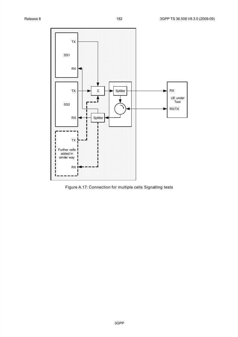
7/15/2019 Lte Sib Info
http://slidepdf.com/reader/full/lte-sib-info 182/187
3GPP
3GPP TS 36.508 V8.3.0 (2009-09)182Release 8
UE under
Test
RX/TX
RXSplitter
SS2
RX
TX
Further cells
added insimilar way
RX
TX
Σ
Splitter
SS1
RX
TX
Figure A.17: Connection for mu ltiple cells Signalling tests

7/15/2019 Lte Sib Info
http://slidepdf.com/reader/full/lte-sib-info 183/187
3GPP
3GPP TS 36.508 V8.3.0 (2009-09)183Release 8
SSTX
RX
RX
UEunder test
TX/RX
Σ
Σ
splitter
AWGNGen 1
AWGNGen 2
Figure A.18: Connection for 1 cell w ith antenna configuration 1x2 in static propagation conditions
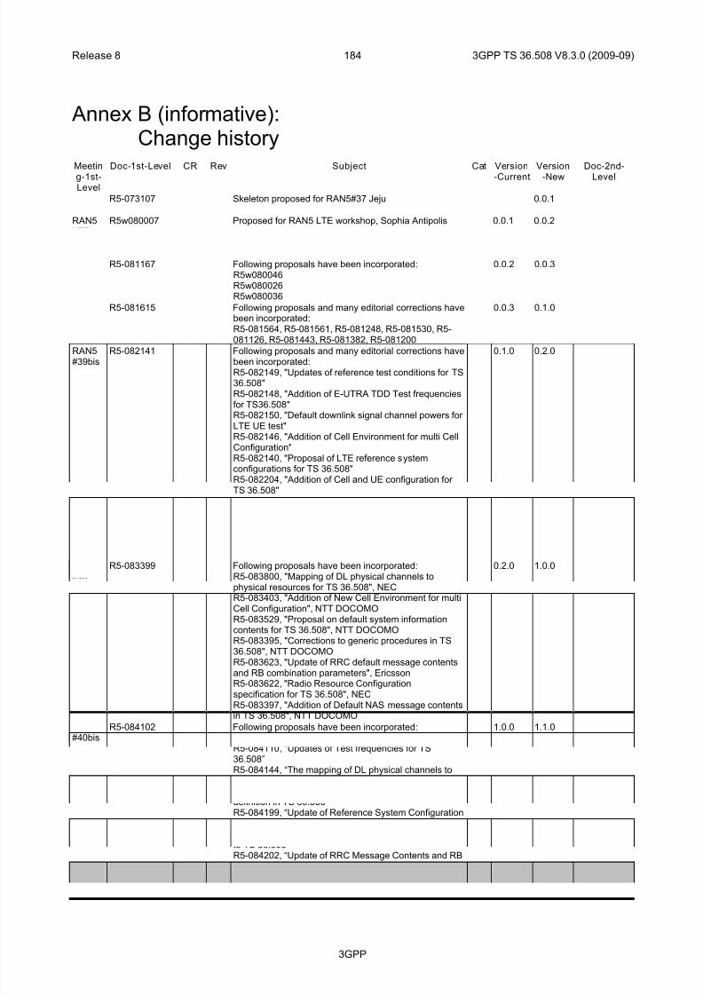
7/15/2019 Lte Sib Info
http://slidepdf.com/reader/full/lte-sib-info 184/187
3GPP
3GPP TS 36.508 V8.3.0 (2009-09)184Release 8
Annex B (informative):Change history
Meeting-1st-Level
Doc-1st-Level CR Rev Subject Cat Version-Current
Version-New
Doc-2nd-Level
RAN5#37
R5-073107 Skeleton proposed for RAN5#37 Jeju 0.0.1
RAN5LTEworkshop
R5w080007 Proposed for RAN5 LTE workshop, Sophia Antipolis 0.0.1 0.0.2
RAN5#39
R5-081167 Following proposals have been incorporated:R5w080046R5w080026R5w080036
0.0.2 0.0.3
RAN5#39
R5-081615 Following proposals and many editorial corrections havebeen incorporated:R5-081564, R5-081561, R5-081248, R5-081530, R5-081126, R5-081443, R5-081382, R5-081200
0.0.3 0.1.0
RAN5#39bis
R5-082141 Following proposals and many editorial corrections havebeen incorporated:R5-082149, "Updates of reference test conditions for TS36.508"R5-082148, "Addition of E-UTRA TDD Test frequenciesfor TS36.508"R5-082150, "Default downlink signal channel powers for LTE UE test"R5-082146, "Addition of Cell Environment for multi CellConfiguration"R5-082140, "Proposal of LTE reference systemconfigurations for TS 36.508"R5-082204, "Addition of Cell and UE configuration for TS 36.508"R5-082090, "Update of default RRC message contents"R5-082100, "Proposal on Structure of Default MessageContents for TS 36.508"R5-082091, "Addition of SRB and DRB radio bearer combinations to 36.508"R5-082173, "Connection Diagrams for TX and RX tests"
0.1.0 0.2.0
RAN5#40
R5-083399 Following proposals have been incorporated:R5-083800, "Mapping of DL physical channels tophysical resources for TS 36.508", NECR5-083403, "Addition of New Cell Environment for multiCell Configuration", NTT DOCOMOR5-083529, "Proposal on default system informationcontents for TS 36.508", NTT DOCOMOR5-083395, "Corrections to generic procedures in TS36.508", NTT DOCOMOR5-083623, "Update of RRC default message contentsand RB combination parameters", EricssonR5-083622, "Radio Resource Configuration
specification for TS 36.508", NECR5-083397, "Addition of Default NAS message contentsin TS 36.508", NTT DOCOMO
0.2.0 1.0.0
RAN5#40bis
R5-084102 Following proposals have been incorporated:R5-084101, “Missing corrections to TS 36.508”R5-084110, “Updates of Test frequencies for TS36.508”R5-084144, “The mapping of DL physical channels tophysical resources for TS 36.508”R5-084198, “Update of RA and RB power ratiosdefinition in TS 36.508”R5-084199, “Update of Reference System Configurationin 36.508”R5-084109, “Addition of default RRC message contentsto TS 36.508”R5-084202, “Update of RRC Message Contents and RB
Configurations in 36.508”R5-084265, “Addition of default RRC message contentsfor handover”R5-084162, “Connection Diagrams for performance
1.0.0 1.1.0

7/15/2019 Lte Sib Info
http://slidepdf.com/reader/full/lte-sib-info 185/187
3GPP
3GPP TS 36.508 V8.3.0 (2009-09)185Release 8
Meeting-1st-Level
Doc-1st-Level CR Rev Subject Cat Version-Current
Version-New
Doc-2nd-Level
tests”
RAN5#41
R5-085145 Following proposals have been incorporated:R5-085087, "Updates of Test frequencies for TS36.508"R5-085701, "Cleaning up section 5 in TS 36.508"
R5-085252, "Correction to Section 4.3.3.2 of TS 36.508"R5-085315, "Connection Diagrams: delete the editorialnote"R5-085454, "Addition of timer tolerances"R5-085566, "Addition of default settings of suitable /non-suitable cells in TS 36.508"R5-085541, "Update to default configurations of simulated cells in TS 36.508"R5-085514, "Update to default configurations of systeminformation blocks in TS 36.508"R5-085472, "Addition of default settings of suitable /non-suitable cells in TS 36.508"R5-085394, "Update of Reference systemconfigurations in 36.508"R5-085457, "Update to generic procedure in TS 36.508"R5-085458, "Addition of new generic procedure to
check the UE does not answer to paging"R5-085523, "Update of default RRC message contents"R5-085381, "Addition to default RRC IE contents for measurement configuration"R5-085469, "Update to default NAS message contentsin TS 36.508"R5-085451, "Parameter settings for reference RBconfigurations"R5-085556, "Common test USIM parameters for EPStesting"
1.1.0 2.0.0
RAN#42
RP-085145 Approval of version 2.0.0 at RAN#42, then updated to v8.0.0.
2.0.0 8.0.0
Editorial corrections. 8.0.0 8.0.1
RAN5#41bis
R5-086021 0001 - Introduction of half cell configurations in eUTRA SS 8.0.1 8.1.0
RAN5#41bis
R5-086166 0002 - Removal of Redundant Environmental Conditions 8.0.1 8.1.0
RAN5#41bis
R5-086221 0003 - CR to 36.508: correction of EARFCN 8.0.1 8.1.0
RAN5#41bis
R5-086226 0004 - Correction to the default system informations in TS36.508
8.0.1 8.1.0
RAN5#41bis
R5-086236 0005 - Connection diagrams for RRM 8.0.1 8.1.0
RAN5#41bis
R5-086346 0006 - Update of the default message AUTHENTICATIONFAILURE
8.0.1 8.1.0
RAN5#41bis
R5-086362 0007 - update of reference configuration systems for CDMA2000 in 36.508
8.0.1 8.1.0
RAN5#41bis
R5-086363 0008 - Updated of common and default parameters for CDMA2000 cells
8.0.1 8.1.0
RAN5#41bis
R5-086364 0009 - Update of SystemInformationBlockType8 in 36.508 8.0.1 8.1.0
RAN5#41bis
R5-086369 0010 - Addition of reference EPS bearer contexts 8.0.1 8.1.0
RAN5#41bis
R5-086370 0011 - Mapping of default DL Physical Channels for TDD in36.508
8.0.1 8.1.0
RAN5#41bis
R5-086400 0012 - Addition of RS_EPRE powers to default DL signal levels 8.0.1 8.1.0
RAN5#42
R5-090084 0013 - Test procedure to verify that an EPS bearer context isactive
8.0.1 8.1.0
RAN5#42
R5-090362 0014 - Correction to the definition of simulated NAS cells in TS36.508
8.0.1 8.1.0
RAN5#42
R5-090464 0015 - Clean up the test algorithm for authentication 8.0.1 8.1.0
RAN5#42
R5-090586 0016 - Add specific information elements for RRCreconfiguration
8.0.1 8.1.0
RAN5
#42
R5-090630 0017 - Introduction of alternative DRX configurations 8.0.1 8.1.0
RAN5#42
R5-090681 0018 - Correction to the default NAS message contents in TS36.508
8.0.1 8.1.0
RAN5#42
R5-090682 0019 - Correction to the definition of simulated cells in TS36.508
8.0.1 8.1.0
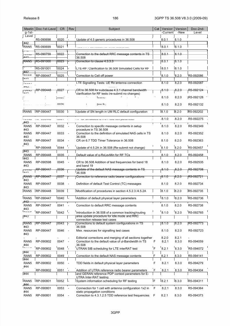
7/15/2019 Lte Sib Info
http://slidepdf.com/reader/full/lte-sib-info 186/187
3GPP
3GPP TS 36.508 V8.3.0 (2009-09)186Release 8
Meeting-1st-Level
Doc-1st-Level CR Rev Subject Cat Version-Current
Version-New
Doc-2nd-Level
RAN5#42
R5-090698 0020 - Update of 4.5 generic procedures in 36.508 8.0.1 8.1.0
RAN5#42
R5-090699 0021 - TDD RTT correction for timer tolerance 8.0.1 8.1.0
RAN5
#42
R5-090759 0022 - Correction to the default RRC message contents in TS
36.508
8.0.1 8.1.0
RAN5#42
R5-091000 0023 - Correction to clause 4.3.3.3 8.0.1 8.1.0
RAN5#42
R5-091001 0024 - LTE-RF: Clarification to 36.508 Simulated Cells for RFtests
8.0.1 8.1.0
RAN5#43
RP-090447 0025 - Correction to Cell off power 8.1.0 8.2.0 R5-092086
RAN5#43
RP-090447 0026 - LTE Signalling Tests: UE Rx antenna connection 8.1.0 8.2.0 R5-092087
RAN5#43
RP-090448 0027 - CR to 36.508 for subclause 4.3.1 channel bandwidthclarification for RF tests (re-submit no changes)
8.1.0 8.2.0 R5-092124
RAN5#43
RP-090448 0028 - Text for 4.2.2: Minimum functional requirements 8.1.0 8.2.0 R5-092128
RAN5#43
RP-090448 0029 - Annex A: transition from 1 to 2 RX antenna 8.1.0 8.2.0 R5-092132
RAN5#43 RP-090447 0030 - Update of SN length in UM RLC default configuration 8.1.0 8.2.0 R5-092202
RAN5#43
RP-090448 0031 - TP for simulated UTRA TDD cell parameter 8.1.0 8.2.0 R5-092275
RAN5#43
RP-090447 0032 - Correction to specific message contents in setupprocedure in TS 36.508
8.1.0 8.2.0 R5-092349
RAN5#43
RP-090447 0033 - Correction to the definition of simulated NAS cells in TS36.508
8.1.0 8.2.0 R5-092352
RAN5#43
RP-090447 0034 - CR on 6.7 TDD Timer Tolerance in 36.508 8.1.0 8.2.0 R5-092363
RAN5#43
RP-090448 0044 - Update of 4.5.2A in 36.508 (Re-submit not change) 8.1.0 8.2.0 R5-092457
RAN5#43
RP-090448 0035 - Default value of q-RxLevMin for RF TCs 8.1.0 8.2.0 R5-092458
RAN5#43
RP-090598 0045 - CR to 36.508 Addition of test frequencies for band 18and band 19
8.1.0 8.2.0 R5-092535
RAN5#43
RP-090447 0036 - Update of the default NAS message contents in TS36.508
8.1.0 8.2.0 R5-092708
RAN5#43
RP-090447 0037 - Correction to reference radio bearer configurations 8.1.0 8.2.0 R5-092721
RAN5#43
RP-090447 0038 - Definition of default Test Control (TC) messages 8.1.0 8.2.0 R5-092734
RAN5#43
RP-090448 0039 - Modification of procedures in section 4.5.2.3 /4.5.2A 8.1.0 8.2.0 R5-092735
RAN5#43
RP-090447 0040 - Addition of default physical layer parameters 8.1.0 8.2.0 R5-092736
RAN5#43
RP-090447 0041 - Correction to default RRC message contents 8.1.0 8.2.0 R5-092738
RAN5#43
RP-090447 0042 - Introduction in 36.508 of a common tracking/routingarea update procedure for Idle mode and RRCconnection release test cases
8.1.0 8.2.0 R5-092765
RAN5
#43
RP-090447 0043 - Corrections to default system configurations in TS
36.508
8.1.0 8.2.0 R5-092773
RAN5#43
RP-090447 0046 - Max. resources for signalling test cases 8.1.0 8.2.0 R5-092723
- - - - Editorial corrections and merging of all sections together 8.2.0 8.2.1 -
RAN5#44
RP-090802 0047 - Correction to the default value of ul-Bandwidth in TS36.508
F 8.2.1 8.3.0 R5-094059
RAN5#44
RP-090802 0048 - UTRAN SIB scheduling for LTE interRAT test F 8.2.1 8.3.0 R5-094072
RAN5#44
RP-090802 0049 - Correction to the default NAS message contents F 8.2.1 8.3.0 R5-094141
RAN5#44
RP-090802 0050 - TDD fields in default physical layer parameters F 8.2.1 8.3.0 R5-094279
RAN5#44
RP-090802 0051 - Addition of UTRA reference radio bearer parametersand GERAN reference PDP context parameters for E-UTRA Inter-RAT testing
F 8.2.1 8.3.0 R5-094304
RAN5#44
RP-090801 0052 - System information scheduling for RF testing F 8.2.1 8.3.0 R5-094311
RAN5#44
RP-090801 0053 - Connection for 1 cell with antenna configuration 1x2 instatic propagation conditions
F 8.2.1 8.3.0 R5-094364
RAN5 RP-090801 0054 - Correction to 4.3.1.2.5 TDD reference test frequencies F 8.2.1 8.3.0 R5-094373

7/15/2019 Lte Sib Info
http://slidepdf.com/reader/full/lte-sib-info 187/187
3GPP TS 36.508 V8.3.0 (2009-09)187Release 8
Meeting-1st-Level
Doc-1st-Level CR Rev Subject Cat Version-Current
Version-New
Doc-2nd-Level
#44 for Operating Band 37
RAN5#44
RP-090801 0055 - LTE RF: Physical Layer configurations for RF/RRMtesting
F 8.2.1 8.3.0 R5-094421
RAN5#44
RP-090802 0056 - Update of SN length in PDCP default configuration F 8.2.1 8.3.0 R5-094533
RAN5#44
RP-090802 0057 - Corrections to default RRC message and IE contents F 8.2.1 8.3.0 R5-094639
RAN5#44
RP-090801 0058 - Update of TDD reference test frequencies for operatingband 40
F 8.2.1 8.3.0 R5-094786
RAN5#44
RP-090810 0059 - TDD special subframe pattern update F 8.2.1 8.3.0 R5-094901
RAN5#44
RP-090802 0060 - corrections to reference RB configurations F 8.2.1 8.3.0 R5-095064
RAN5#44
RP-090802 0061 - Correction of test procedure 6.4.2.7 in TS 36.508 F 8.2.1 8.3.0 R5-095093
RAN5#44
RP-090802 0062 - Adding new elementary files to the default USIMsettings
F 8.2.1 8.3.0 R5-095100
RAN5#44
RP-090802 0063 - Correction to the Test procedure to check RRC_IDLEstate
F 8.2.1 8.3.0 R5-095102
RAN5
#44
RP-090802 0064 - Introduction of UE mode of operation into NAS default
message contents
F 8.2.1 8.3.0 R5-095138
RAN5#44
RP-090802 0065 - TDD ACK/NACK feedback mode update F 8.2.1 8.3.0 R5-095152
RAN5#44
RP-090802 0066 - Corrections to default signal levels F 8.2.1 8.3.0 R5-095206
RAN5#44
RP-090802 0067 - Update to default messages in regard to IP addressallocation
F 8.2.1 8.3.0 R5-095218