lte fixed mobile convergence with ics telecom - atdi inc · white paper january 2009 lte fixed...
TRANSCRIPT

White Paper January 2009 LTE fixed mobile convergence with ICS telecom Daniel Humire
Software solutions in radiocommunications

Abstract
By now, many established telecom operators around the world are investigating or have already decided on adopting LTE as their 3.5G‐4G transition technology of choice. The relative ease in which LTE can be adopted into existing 3GPP based infrastructure has been a major factor in turning the attention of many operators to LTE. LTE is a true mobile technology – with options to offer FWA type services (FTP downloads, video streaming, etc.). The migration to LTE is allowing operators to approach true fixed mobile convergence service for the emerging laptop consumer as well as the usual handset customer. For existing ATDI customers the advantages of using ICS telecom, ATDI’s flagship commercial RF network design package, for modeling the issues related to technology convergence are already understood and appreciated. ICS telecom not only possesses a robust FWA design engine with several years of continuous development and refinement, but also the most comprehensive propagation engine for generating area coverage plots and reports at any frequency band from 10 KHZ – 400 GHZ. ICS telecom can assist an established operator in building out or optimizing their existing network. In particular, ICS telecom aids an RF network design engineer in dealing with technology convergence issues as they relate to interference mitigation such as adjacent channel interference, cosite and out of band interference issues and spectral optimization – all analytical requirements not met by the vast majority of today’s commercial RF network planning tools. In this document we will review how ICS telecom can already handle the main features of the LTE technology for providing complete computer based network design including initial site placement dimensioning, parameters optimization and validation. Some of these modeling features applicable to LTE design are highlighted below and will be presented in more detail throughout this paper:
Site selection/optimization – From Fiber Hub to backhaul as well as multipoint access layers. The tool includes options for automatic site candidate filtering (computer aided auto‐planning).
Network coverage calculation – includes throughput prediction plots considering LTE specific configuration of tool’s results to reflect LTE service classes (conversational, web navigation, streaming, FTP).

Interference mitigation – Beginning with DL and UL interference analysis based on SINR calculations, the tool can also consider synchronization issues specific to OFDM technology as well as simulcast mitigation for SFN. The COFDM interference engine allows consideration of MBMS (Multimedia Broadcast Multicast Services) network management issues. Out of band interference issues such as intermodulation are also considered.
Automatic frequency assignment and adjacent channel interference for MFN – ICS telecom can consider both TDD and FDD frame types. In the case of FDD frame types, ICS telecom can assign frequencies to a full duplex (Tx and Rx per sector). Each sector in ICS telecom can have over 16 transmitting and receiving channels assigned thus allowing the user to also realize adjacent channel interference issues which are critical when combining or replacing established technologies such as W‐CDMA/EDGE with LTE.
Correlation with field measurements – ICS telecom allows a user to improve the accuracy of their preferred propagation model through auto‐correlation analysis of field measurements and the tool’s predictions. Standard deviation per clutter code can be generated and applied to customer specific optimization procedures.
Interference analysis with a Monte‐Carlo simulator – Variable site and equipment parameters can be considered such as location, transmit and receive height, power, bandwidth, operating frequency, antenna gain, etc. to model interference issues between new service areas and adjacent networks. ICS telecom’s Monte‐Carlo engine allows a user to generate all manners of interference issues to consider mobility not just on the ground, but within buildings as well.

2
Table of Content
1 Site selection/optimization ______________________________________________________ 4
1.1 Computer Aided Network Dimensioning _____________________________________ 5
2 Network Coverage Calculation __________________________________________________ 7
2.1 Configuring coverage report to display LTE service classes _____________________ 7
3 Interference mitigation ________________________________________________________ 8
3.1 OFDMA downlink _______________________________________________________ 8
3.2 SC-FDMA uplink _______________________________________________________ 11
3.3 SFN Simulcast __________________________________________________________ 12
4 Automatic Frequency Assignment for MFN ______________________________________ 12
5 Correlation with Field Measurements ___________________________________________ 14
6 Interference analysis with Monte-Carlo Simulator _________________________________ 16

4
4
4/18
MOBILE LTE NETWORK DESIGN WITH ICS TELECOM
Note: all values are FOR MARKETING PURPOSES ONLY and do not describe the LTE products of any specific equipment vendor
1 Site selection/optimization
As new commercial communication technologies emerge, there is a greater dependence on intelligent modeling and design procedures in order to deploy new service offerings in a cost‐effective manner to an existing customer base. ICS telecom offers several options for aiding an RF network design engineer in dimensioning the size of their network and identifying the best locations to deploy repeaters / relays in the case of augmenting an established cellular network from a list of candidates. Whether the customer is building out a backhaul to support a new technology, or covering up drop outs with relays, ICS telecom offers a suite of propagation based filters, and user configurable site placement algorithms to facilitate and optimize site acquisition efforts, test and improve the accuracy of link budget calculations and more.
18 GHZ backhaul design with ICS telecom – Blue points represent Fiber points, red points represent existing MW
towers. In this example, the tool’s auto‐planning features were asked to identify the best backhaul link configurations between imported Fiber locations and imported candidate MW link locations, with consideration of a single hop at most.

5
5
5/18
In the case of the design of an LTE network, ICS telecom could allow a user to identify relay locations that can help densify an existing network. An RF network design engineer can get a head start on identifying the network size in particular the number of BS / relay stations necessary to densify the existing network to offer new service levels:
700 MHZ relay predeployment site filtering with ICS telecom – Existing markets can have more service options be made available and new markets can be reached with simple relay planning. In this example, ICS telecom’s propagation based site filter known as its Search Site filter can highlight the best locations to place a relay. In the absence of site data, and for the purposes of expediting and facilitating site acquisition efforts, these simple reports can tell a user in terms of
percentage what locations in their area of interest would best serve the rest of the target market (houses and roadways in this case).
1.1 Computer Aided Network Dimensioning ICS telecom offers an auto site placement feature that takes into consideration budgeting criteria, propagation model of preference, equipment parameters (antenna patterns, number of sectors/site, transmitting power, operational frequency, receiver thresholds, etc.) and all candidate locations and even existing coverage in the case of filling coverage gaps. The auto site placement feature, known as ‘Prospective

6
6
6/18
Planning’ allows the user to isolate the premiere locations to deploy relays for the purposes of optimizing site acquisition efforts.
Based on a user generated database of receiver locations within an area of interest, the Prospective Planning feature will run an uplink coverage assuming a handset’s power every 1‐10 pixels. The user can define how many uplink coverage plots need to overlap a candidate pixel where a BS /relay would be placed. So if a sector needs to be able to support up to 30 handsets at any given time, the user can specify that a candidate location will only be considered if it is overlapped by the uplink coverage of 30 handset locations within the range of that candidate location. Traffic demand characteristics of the handsets and capacity limits of the sector equipment can also be considered during the Prospective Planning process:

7
7
7/18
2 Network Coverage Calculation
ICS telecom contains the most comprehensive propagation engine on the market today. Not only does the tool include popular statistical models such as Okumura‐Hata, Erceg SUI and COST‐231 (including variations of the same such as the Hata‐COST model), it also includes deterministic options that the user can configure and test in cases where they have access to high fidelity digital cartography exceeding the modeling limits of statistically oriented models such as those named previously.
2.1 Configuring coverage report to display LTE service classes ICS telecom bases all its calculations and analyses on the results of its signal strength predictions. These predictions can be used to generate interference mitigation studies, assign frequencies to existing radio equipment or model different service classes based on pre‐defined threshold levels (C/I or receiver signal strength sensitivity):

8
8
8/18
ICS telecom allows its users to redefine coverage calculations in terms of signal strengths thresholds (dBu below) or C/I margins:
This definition of service levels can be applied to the tool’s color coded coverage legend.
Adaptive modulation schemes can also be generated by manipulating the tool’s display palette. UL/DL CINR plots can be generated in this fashion, describing the service levels in terms of C/N+I margins defined in the customizable legend palette box demonstrated above. Rx antenna discrimination margins as well as rejection filters can be considered during interference analyses.
3 Interference mitigation
3.1 OFDMA downlink
As a consequence of the way bandwidth is used by OFDMA technology, an OFDMA signal received from multiple users must consider intersymbol interference effects such as constructive and destructive field strength effects. However, in order to properly calibrate the necessary modeling parameters (Rx sensitivity, total throughput, system gain) ATDI has developed calculators. These calculators help an RF network design engineer interpret how changes in the bandwidth, increase in number of subcarriers, or changes in subchannelization schemes affect the overall throughput and receiver sensitivity. ICS telecom users are aware that base throughput and receive sensitivity values are inputs into the description of a transmitting or
“In contrast to an OFDM transmission scheme, OFDMA allows the access of multiple users on the available bandwidth. Each user is assigned a specific time‐frequency resource. As a fundamental principle of E‐UTRA, the data channels are shared channels, i.e. for each transmission time interval of 1 ms, a new scheduling decision is taken regarding which users are assigned to which time/frequency resources during this transmission time interval.” – LTE

9
9
9/18
receiving element used by the tool to configure the tool in anticipation of generating appropriate signal strength and service level predictions:
In turn, once the parameters of network and how the equipment is expected to behave have been properly described to the tool, ICS telecom offers a variety of options for modeling interference in terms of C/I criteria, IRF criteria as well as in consideration of synchronization issues due to multipath that can result in interference. Synchronization studies, that reveal cases of intersymbol or interchannel interference common with OFDM technologies, can be realized between a single radio transreceiver and its environment, and also for an entire network.
ICS telecom offers a true ray‐tracing engine that can be calibrated via an OFDM parameters box for simulating multipath reflection can highlight the cases where the signal is damaged due to the reflected signal being greater (by a user‐defined margin in dB) than the direct path threshold and with a ToA outside of the OFDM receiver Guard interval:

10
10
10/18
Constructive and Destructive OFDM signals in ICS telecom
Adaptive antennas (MIMO) are also supported for mitigating interference issues. For large scale studies, where the RF design engineer must consider the effect of multipath between various servers within the same network, in some cases within the same frequency, ICS telecom offers a COFDM interference box that can call the tool’s ray tracing engine to model the multipath effect between different servers:
ICS telecom’s COFDM interference engine allows a user to define not only the synchronization criteria (First Server, Best Server, etc.) for a single frequency network, the tool allows the user to define the synchronization parameters in terms of Guard Interval and Usable Symbol Time. Also, the user can specify if their system will consider the positive and negative effects of Inter‐Symbol Interference in terms of constructive and destructive field strength effects. In the case of LTE technology, the user can consider the gain from the OFDM channel due to multipath arriving at a receiver location from not just one but multiple servers operating in the same frequency:

11
11
11/18
3.2 SC-FDMA uplink In the case of uplink based SC‐FDMA interference analysis, ICS telecom can allow the user to generate uplink coverage plots utilizing specific handset parameters including individual transmit and receive frequencies:
Uplink I/N maps generated by the tool also allow a user to model potential interference issues by new service areas on other incumbent systems:

12
12
12/18
I/N map to existing network: In this example, handsets (with the type of specific parameters described above) were placed in memory every two pixels on the digital terrain map. Reverse profiles to the two sectors shown were run and the PR along those path profiles were
compared to the noise floor (‐105 dBm) of both sectors BS1Sec1 and BS2Sec2. The software compared the reverse path profiles to the noise floor to generate an I/N map.
Such maps can assist new spectrum licensees in establishing whether their new services using new,
recently acquired spectrum, will interfere with incumbent government systems or other established commercial
networks in the area.
3.3 SFN Simulcast The key criterion to deploying a single frequency network is being able to assign a launch delay to relays in order to minimize interference issues in key market/service areas. With ICS telecom, the user can automatically assign a launch delay per relay in order to increase the C/N+I margins calculated by the tool’s COFDM interference engine:
Simulcast Criterion
Relay Parameters
4 Automatic Frequency Assignment for MFN
The technique of Orthogonal Frequency Division Multiplexing (OFDM) is based on the well‐known technique of Frequency Division Multiplexing (FDM). In FDM different streams of information are mapped onto separate
13
13
13/18
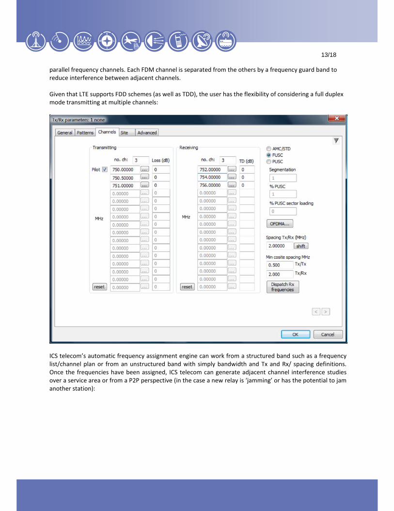
parallel frequency channels. Each FDM channel is separated from the others by a frequency guard band to reduce interference between adjacent channels. Given that LTE supports FDD schemes (as well as TDD), the user has the flexibility of considering a full duplex mode transmitting at multiple channels:
ICS telecom’s automatic frequency assignment engine can work from a structured band such as a frequency list/channel plan or from an unstructured band with simply bandwidth and Tx and Rx/ spacing definitions. Once the frequencies have been assigned, ICS telecom can generate adjacent channel interference studies over a service area or from a P2P perspective (in the case a new relay is ‘jamming’ or has the potential to jam another station):

14
14
14/18
P2P Adjacent Channel interference analysis – Highlighted is a transmitter that is experiencing 2.57 dB in
threshold degredation due to Station 1 being interference by Station 2 whereas Station 1 is operating at 756 MHZ and Station 2 has a transmitting channel operating at 751 MHZ. In this case, a 10 MHZ bandwidth is
being used.
5 Correlation with Field Measurements
As with any RF modeling package, ICS telecom comes with a robust prediction to measurement correlation interface that allows the user to ‘tune’ the propagation algorithm of their choice based on empirically recorded information about signal strength readings taken in the field. Measurement data from a variety of vendor equipment formats can be directly imported and used in the tool to compare with the tool’s predictions, as well as generic file formats detailing the signal strength measured per coordinate can be used:

15
15
15/18
Measurements imported onto ICS telecom digital terrain model. Colors represent signal strength values and green square represents station location. By default, blue refers to the weakest signals measured and red/brown refers to the strongest signals measured.
At this point, ICS telecom can correlate the measurements vs. the tool’s prediction on a pixel by pixel basis to generate what it determines to be the tool’s level of accuracy in terms of percentage and standard deviation:

16
16
16/18
The statistics generated by this analysis can in turn be used to automatically tune variables in the propagation model configuration, namely clutter attenuations. Quite often, even without tuning processes implemented, ICS telecom can generate 60‐80% correlation accuracy with < 4 dB standard deviation prior to any ‘tuning’ or mathematically derived attenuations to automatically associate to the clutter.
6 Interference analysis with Monte-Carlo Simulator
ICS telecom allows users to generate interference studies using a Monte‐Carlo engine that can consider ranges in equipment parameters such power, gain, frequency, bandwidth as well as location and transmit height. This can allow a user to model interference issues in the case of handsets on the street and handsets in the third floor of a building. The result would be a statistical report that would dictate probability of interference over and below a certain threshold such as C/I or I/N or C/N, etc. In the examples below, random handsets were generated on a map with two base station coverage areas. The software tested for adjacent channel interference issues between stations operation at 815 MHZ and handsets operating at a range of 735 MHZ and 775 MHZ with 10 MHZ bandwidth separation. The resulting analysis stated that 92.38% of all cases resulted in no interference. The analysis included variable power, gain and height settings.

17
17
17/18

18
18
18/19
ATDI Ibérica C/ Orense, 8 Piso 12-D (Nuevos Ministerios) 28020 Madrid - España Tel. +34 91 598 21 36 Fax +34 91 597 03 01 E-mail : [email protected] Website : www.atdi.es
ATDI SA (International) 8, rue de l'Arcade 75008 Paris, France Tel. +33 (0)1 53 30 89 40 Fax +33 (0)1 53 30 89 49 E-mail : [email protected] Website : www.atdi.fr
ATDI Inc. (Americas) 1420 Beverly Road, Suite 140 McLean, VA 22101 - USA Tel. +1 703 848 4750 Fax +1 703 848 4752 Email : [email protected] Website www.atdi-us.com
ATDI Ltd. (Northern Europe) Kingsland Court, Three Bridges Road Crawley West Sussex RH10 1HL, United Kingdom Tel. +44 (0) 1293 522 052 Fax +44 (0) 1293 522 521 E-mail : [email protected] Website www.atdi.co.uk
ATDI EST Bd. Aviatorilor, nr 59 Bucharest - Romania Tel. +40 21 222 42 10 Tel./Fax +40 21 222 42 13 E-mail : [email protected] Website www.atdi.ro
LLC ATDI Eurasia (Russia & CIS) Sadovnicheskaya str, 72 bld 1 115035 Moscow - Russian Federation Tel. + 7 499 929 96 10 Tel./Fax + 7 499 929 90 01 E-mail : [email protected] Website www.atdi.ru / www.atdi-eurasia.com
ATDI South Pacific PTY Ltd 79 Macarthur Street - Ultimo NSW 2007 - Australia Tel. +61 (0)2 9213 2200 Tel./Fax +61 (0)2 9213 2299 E-mail : [email protected] Website www.atdi-pacific.com
ATDI UA in partnership with LIS Gmyri Str. 9-V, 6th porch, Office 211 (Ground floor), 02068 Kiev - Ukraine Tel. +38 044 594 1343 Fax +38 044 239 9813 E-mail : [email protected] or [email protected] Website www.lissoft.com.ua
ATDI Germany Kurze Mühen 1 / Spitaler Hof 20095 Hamburg - Germany Tel. +49 40 32901 226 Fax +49 40 32901 100 E-mail : [email protected] Website www.atdi-de.com
ATDI Scandinavia Kirkåsveien 38 1850 Mysen - Norway Tel. +47 69 89 58 00 Fax +47 69 89 58 01 E-mail : [email protected] Website www.atdi.no