lte; evolved universal terrestrial radio access (e-utra); physical
TRANSCRIPT
ETSI TS 136 211 V11.5.0 (2014-01)
LTE; Evolved Universal Terrestrial Radio Access (E-UTRA);
Physical channels and modulation (3GPP TS 36.211 version 11.5.0 Release 11)
Technical Specification
ETSI
ETSI TS 136 211 V11.5.0 (2014-01)13GPP TS 36.211 version 11.5.0 Release 11
Reference RTS/TSGR-0136211vb50
Keywords LTE
ETSI
650 Route des Lucioles F-06921 Sophia Antipolis Cedex - FRANCE
Tel.: +33 4 92 94 42 00 Fax: +33 4 93 65 47 16
Siret N° 348 623 562 00017 - NAF 742 C
Association à but non lucratif enregistrée à la Sous-Préfecture de Grasse (06) N° 7803/88
Important notice
Individual copies of the present document can be downloaded from: http://www.etsi.org
The present document may be made available in more than one electronic version or in print. In any case of existing or perceived difference in contents between such versions, the reference version is the Portable Document Format (PDF).
In case of dispute, the reference shall be the printing on ETSI printers of the PDF version kept on a specific network drive within ETSI Secretariat.
Users of the present document should be aware that the document may be subject to revision or change of status. Information on the current status of this and other ETSI documents is available at
http://portal.etsi.org/tb/status/status.asp
If you find errors in the present document, please send your comment to one of the following services: http://portal.etsi.org/chaircor/ETSI_support.asp
Copyright Notification
No part may be reproduced except as authorized by written permission. The copyright and the foregoing restriction extend to reproduction in all media.
© European Telecommunications Standards Institute 2014.
All rights reserved.
DECTTM, PLUGTESTSTM, UMTSTM and the ETSI logo are Trade Marks of ETSI registered for the benefit of its Members. 3GPPTM and LTE™ are Trade Marks of ETSI registered for the benefit of its Members and
of the 3GPP Organizational Partners. GSM® and the GSM logo are Trade Marks registered and owned by the GSM Association.

ETSI
ETSI TS 136 211 V11.5.0 (2014-01)23GPP TS 36.211 version 11.5.0 Release 11
Intellectual Property Rights IPRs essential or potentially essential to the present document may have been declared to ETSI. The information pertaining to these essential IPRs, if any, is publicly available for ETSI members and non-members, and can be found in ETSI SR 000 314: "Intellectual Property Rights (IPRs); Essential, or potentially Essential, IPRs notified to ETSI in respect of ETSI standards", which is available from the ETSI Secretariat. Latest updates are available on the ETSI Web server (http://ipr.etsi.org).
Pursuant to the ETSI IPR Policy, no investigation, including IPR searches, has been carried out by ETSI. No guarantee can be given as to the existence of other IPRs not referenced in ETSI SR 000 314 (or the updates on the ETSI Web server) which are, or may be, or may become, essential to the present document.
Foreword This Technical Specification (TS) has been produced by ETSI 3rd Generation Partnership Project (3GPP).
The present document may refer to technical specifications or reports using their 3GPP identities, UMTS identities or GSM identities. These should be interpreted as being references to the corresponding ETSI deliverables.
The cross reference between GSM, UMTS, 3GPP and ETSI identities can be found under http://webapp.etsi.org/key/queryform.asp.
ETSI
ETSI TS 136 211 V11.5.0 (2014-01)33GPP TS 36.211 version 11.5.0 Release 11
Contents
Intellectual Property Rights ................................................................................................................................ 2
Foreword ............................................................................................................................................................. 2
Foreword ............................................................................................................................................................. 6
1 Scope ........................................................................................................................................................ 7
2 References ................................................................................................................................................ 7
3 Symbols and abbreviations ....................................................................................................................... 7
3.1 Symbols .............................................................................................................................................................. 7
3.2 Abbreviations ..................................................................................................................................................... 9
4 Frame structure ....................................................................................................................................... 10
4.1 Frame structure type 1 ...................................................................................................................................... 10
4.2 Frame structure type 2 ...................................................................................................................................... 11
5 Uplink ..................................................................................................................................................... 13
5.1 Overview .......................................................................................................................................................... 13
5.1.1 Physical channels ........................................................................................................................................ 13
5.1.2 Physical signals ........................................................................................................................................... 13
5.2 Slot structure and physical resources................................................................................................................ 13
5.2.1 Resource grid .............................................................................................................................................. 13
5.2.2 Resource elements ...................................................................................................................................... 15
5.2.3 Resource blocks .......................................................................................................................................... 15
5.3 Physical uplink shared channel ........................................................................................................................ 16
5.3.1 Scrambling .................................................................................................................................................. 16
5.3.2 Modulation .................................................................................................................................................. 17
5.3.2A Layer mapping ............................................................................................................................................ 18
5.3.2A.1 Layer mapping for transmission on a single antenna port ..................................................................... 18
5.3.2A.2 Layer mapping for spatial multiplexing ................................................................................................ 18
5.3.3 Transform precoding................................................................................................................................... 19
5.3.3A Precoding .................................................................................................................................................... 19
5.3.3A.1 Precoding for transmission on a single antenna port ............................................................................. 19
5.3.3A.2 Precoding for spatial multiplexing ........................................................................................................ 19
5.3.4 Mapping to physical resources.................................................................................................................... 22
5.4 Physical uplink control channel ........................................................................................................................ 24
5.4.1 PUCCH formats 1, 1a and 1b ..................................................................................................................... 24
5.4.2 PUCCH formats 2, 2a and 2b ..................................................................................................................... 27
5.4.2A PUCCH format 3 ........................................................................................................................................ 28
5.4.3 Mapping to physical resources.................................................................................................................... 30
5.5 Reference signals .............................................................................................................................................. 31
5.5.1 Generation of the reference signal sequence ............................................................................................... 31
5.5.1.1 Base sequences of length RBsc3N or larger ............................................................................................ 31
5.5.1.2 Base sequences of length less than RBsc3N ............................................................................................ 32
5.5.1.3 Group hopping ...................................................................................................................................... 34
5.5.1.4 Sequence hopping ................................................................................................................................. 35
5.5.1.5 Determining virtual cell identity for sequence generation .................................................................... 35
5.5.2 Demodulation reference signal ................................................................................................................... 36
5.5.2.1 Demodulation reference signal for PUSCH .......................................................................................... 36
5.5.2.1.1 Reference signal sequence ............................................................................................................... 36
5.5.2.1.2 Mapping to physical resources ........................................................................................................ 38
5.5.2.2 Demodulation reference signal for PUCCH .......................................................................................... 38
5.5.2.2.1 Reference signal sequence ............................................................................................................... 38
5.5.2.2.2 Mapping to physical resources ........................................................................................................ 39
5.5.3 Sounding reference signal ........................................................................................................................... 41
5.5.3.1 Sequence generation.............................................................................................................................. 41
5.5.3.2 Mapping to physical resources .............................................................................................................. 41

ETSI
ETSI TS 136 211 V11.5.0 (2014-01)43GPP TS 36.211 version 11.5.0 Release 11
5.5.3.3 Sounding reference signal subframe configuration ............................................................................... 44
5.6 SC-FDMA baseband signal generation ............................................................................................................ 45
5.7 Physical random access channel ....................................................................................................................... 46
5.7.1 Time and frequency structure ..................................................................................................................... 46
5.7.2 Preamble sequence generation .................................................................................................................... 52
5.7.3 Baseband signal generation......................................................................................................................... 55
5.8 Modulation and upconversion .......................................................................................................................... 56
6 Downlink ................................................................................................................................................ 57
6.1 Overview .......................................................................................................................................................... 57
6.1.1 Physical channels ........................................................................................................................................ 57
6.1.2 Physical signals ........................................................................................................................................... 57
6.2 Slot structure and physical resource elements .................................................................................................. 58
6.2.1 Resource grid .............................................................................................................................................. 58
6.2.2 Resource elements ...................................................................................................................................... 59
6.2.3 Resource blocks .......................................................................................................................................... 60
6.2.3.1 Virtual resource blocks of localized type .............................................................................................. 60
6.2.3.2 Virtual resource blocks of distributed type ........................................................................................... 60
6.2.4 Resource-element groups ............................................................................................................................ 62
6.2.4A Enhanced Resource-Element Groups (EREGs) .......................................................................................... 63
6.2.5 Guard period for half-duplex FDD operation ............................................................................................. 63
6.2.6 Guard Period for TDD Operation ............................................................................................................... 63
6.3 General structure for downlink physical channels ............................................................................................ 64
6.3.1 Scrambling .................................................................................................................................................. 64
6.3.2 Modulation .................................................................................................................................................. 64
6.3.3 Layer mapping ............................................................................................................................................ 65
6.3.3.1 Layer mapping for transmission on a single antenna port ..................................................................... 65
6.3.3.2 Layer mapping for spatial multiplexing ................................................................................................ 66
6.3.3.3 Layer mapping for transmit diversity .................................................................................................... 67
6.3.4 Precoding .................................................................................................................................................... 67
6.3.4.1 Precoding for transmission on a single antenna port ............................................................................. 67
6.3.4.2 Precoding for spatial multiplexing using antenna ports with cell-specific reference signals ................ 67
6.3.4.2.1 Precoding without CDD .................................................................................................................. 68
6.3.4.2.2 Precoding for large delay CDD ....................................................................................................... 68
6.3.4.2.3 Codebook for precoding and CSI reporting ..................................................................................... 69
6.3.4.3 Precoding for transmit diversity ............................................................................................................ 70
6.3.4.4 Precoding for spatial multiplexing using antenna ports with UE-specific reference signals................. 71
6.3.5 Mapping to resource elements .................................................................................................................... 72
6.4 Physical downlink shared channel .................................................................................................................... 73
6.5 Physical multicast channel ............................................................................................................................... 73
6.6 Physical broadcast channel ............................................................................................................................... 74
6.6.1 Scrambling .................................................................................................................................................. 74
6.6.2 Modulation .................................................................................................................................................. 74
6.6.3 Layer mapping and precoding .................................................................................................................... 74
6.6.4 Mapping to resource elements .................................................................................................................... 74
6.7 Physical control format indicator channel ........................................................................................................ 75
6.7.1 Scrambling .................................................................................................................................................. 75
6.7.2 Modulation .................................................................................................................................................. 75
6.7.3 Layer mapping and precoding .................................................................................................................... 75
6.7.4 Mapping to resource elements .................................................................................................................... 76
6.8 Physical downlink control channel ................................................................................................................... 77
6.8.1 PDCCH formats .......................................................................................................................................... 77
6.8.2 PDCCH multiplexing and scrambling ........................................................................................................ 77
6.8.3 Modulation .................................................................................................................................................. 77
6.8.4 Layer mapping and precoding .................................................................................................................... 78
6.8.5 Mapping to resource elements .................................................................................................................... 78
6.8A Enhanced physical downlink control channel .................................................................................................. 79
6.8A.1 EPDCCH formats ....................................................................................................................................... 79
6.8A.2 Scrambling .................................................................................................................................................. 80
6.8A.3 Modulation .................................................................................................................................................. 80
6.8A.4 Layer mapping and precoding .................................................................................................................... 80
6.8A.5 Mapping to resource elements .................................................................................................................... 80
ETSI
ETSI TS 136 211 V11.5.0 (2014-01)53GPP TS 36.211 version 11.5.0 Release 11
6.9 Physical hybrid ARQ indicator channel ........................................................................................................... 82
6.9.1 Modulation .................................................................................................................................................. 82
6.9.2 Resource group alignment, layer mapping and precoding .......................................................................... 83
6.9.3 Mapping to resource elements .................................................................................................................... 85
6.10 Reference signals .............................................................................................................................................. 87
6.10.1 Cell-specific Reference Signal (CRS)......................................................................................................... 87
6.10.1.1 Sequence generation.............................................................................................................................. 87
6.10.1.2 Mapping to resource elements............................................................................................................... 87
6.10.2 MBSFN reference signals ........................................................................................................................... 90
6.10.2.1 Sequence generation.............................................................................................................................. 90
6.10.2.2 Mapping to resource elements............................................................................................................... 90
6.10.3 UE-specific reference signals associated with PDSCH .............................................................................. 92
6.10.3.1 Sequence generation.............................................................................................................................. 92
6.10.3.2 Mapping to resource elements............................................................................................................... 93
6.10.3A Demodulation reference signals associated with EPDCCH ........................................................................ 98
6.10.3A.1 Sequence generation.............................................................................................................................. 98
6.10.3A.2 Mapping to resource elements............................................................................................................... 98
6.10.4 Positioning reference signals .................................................................................................................... 100
6.10.4.1 Sequence generation............................................................................................................................ 100
6.10.4.2 Mapping to resource elements............................................................................................................. 100
6.10.4.3 Positioning reference signal subframe configuration .......................................................................... 101
6.10.5 CSI reference signals ................................................................................................................................ 103
6.10.5.1 Sequence generation............................................................................................................................ 103
6.10.5.2 Mapping to resource elements............................................................................................................. 103
6.10.5.3 CSI reference signal subframe configuration ...................................................................................... 107
6.11 Synchronization signals .................................................................................................................................. 108
6.11.1 Primary synchronization signal ................................................................................................................. 108
6.11.1.1 Sequence generation............................................................................................................................ 108
6.11.1.2 Mapping to resource elements............................................................................................................. 108
6.11.2 Secondary synchronization signal ............................................................................................................. 109
6.11.2.1 Sequence generation............................................................................................................................ 109
6.11.2.2 Mapping to resource elements............................................................................................................. 110
6.12 OFDM baseband signal generation ................................................................................................................ 112
6.13 Modulation and upconversion ........................................................................................................................ 112
7 Generic functions ................................................................................................................................. 113
7.1 Modulation mapper ........................................................................................................................................ 113
7.1.1 BPSK .............................................................................................................................................................. 113
7.1.2 QPSK .............................................................................................................................................................. 113
7.1.3 16QAM .......................................................................................................................................................... 114
7.1.4 64QAM .......................................................................................................................................................... 115
7.2 Pseudo-random sequence generation.............................................................................................................. 116
8 Timing .................................................................................................................................................. 116
8.1 Uplink-downlink frame timing ....................................................................................................................... 116
Annex A (informative): Change history ............................................................................................. 117
History ............................................................................................................................................................ 121
ETSI
ETSI TS 136 211 V11.5.0 (2014-01)63GPP TS 36.211 version 11.5.0 Release 11
Foreword This Technical Specification has been produced by the 3rd Generation Partnership Project (3GPP).
The contents of the present document are subject to continuing work within the TSG and may change following formal TSG approval. Should the TSG modify the contents of the present document, it will be re-released by the TSG with an identifying change of release date and an increase in version number as follows:
Version x.y.z
where:
x the first digit:
1 presented to TSG for information;
2 presented to TSG for approval;
3 or greater indicates TSG approved document under change control.
y the second digit is incremented for all changes of substance, i.e. technical enhancements, corrections, updates, etc.
z the third digit is incremented when editorial only changes have been incorporated in the document.
ETSI
ETSI TS 136 211 V11.5.0 (2014-01)73GPP TS 36.211 version 11.5.0 Release 11
1 Scope The present document describes the physical channels for evolved UTRA.
2 References The following documents contain provisions which, through reference in this text, constitute provisions of the present document.
• References are either specific (identified by date of publication, edition number, version number, etc.) or non-specific.
• For a specific reference, subsequent revisions do not apply.
• For a non-specific reference, the latest version applies. In the case of a reference to a 3GPP document (including a GSM document), a non-specific reference implicitly refers to the latest version of that document in the same Release as the present document.
[1] 3GPP TR 21.905: "Vocabulary for 3GPP Specifications".
[2] 3GPP TS 36.201: "Evolved Universal Terrestrial Radio Access (E-UTRA); LTE physical layer; General description".
[3] 3GPP TS 36.212: "Evolved Universal Terrestrial Radio Access (E-UTRA); Multiplexing and channel coding".
[4] 3GPP TS 36.213: "Evolved Universal Terrestrial Radio Access (E-UTRA); Physical layer procedures".
[5] 3GPP TS 36.214: "Evolved Universal Terrestrial Radio Access (E-UTRA); Physical layer; Measurements".
[6] 3GPP TS 36.104: "Evolved Universal Terrestrial Radio Access (E-UTRA); Base Station (BS) radio transmission and reception".
[7] 3GPP TS 36.101: "Evolved Universal Terrestrial Radio Access (E-UTRA); User Equipment (UE) radio transmission and reception".
[8] 3GPP TS 36.321, "Evolved Universal Terrestrial Radio Access (E-UTRA); Medium Access Control (MAC) protocol specification".
3 Symbols and abbreviations
3.1 Symbols For the purposes of the present document, the following symbols apply:
),( lk Resource element with frequency-domain index k and time-domain index l )(
,plka Value of resource element ),( lk [for antenna port p ]
D Matrix for supporting cyclic delay diversity
RAD Density of random access opportunities per radio frame
0f Carrier frequency
ETSI
ETSI TS 136 211 V11.5.0 (2014-01)83GPP TS 36.211 version 11.5.0 Release 11
RAf PRACH resource frequency index within the considered time-domain location PUSCHscM Scheduled bandwidth for uplink transmission, expressed as a number of subcarriers PUSCHRBM Scheduled bandwidth for uplink transmission, expressed as a number of resource blocks (q)M bit Number of coded bits to transmit on a physical channel [for codeword q ] (q)M symb Number of modulation symbols to transmit on a physical channel [for codeword q ]
layersymbM Number of modulation symbols to transmit per layer for a physical channel
apsymbM Number of modulation symbols to transmit per antenna port for a physical channel
N A constant equal to 2048 for kHz 15=Δf and 4096 for kHz 5.7=Δf
lN ,CP Downlink cyclic prefix length for OFDM symbol l in a slot
CSN Cyclic shift value used for random access preamble generation (1)csN Number of cyclic shifts used for PUCCH formats 1/1a/1b in a resource block with a mix of
formats 1/1a/1b and 2/2a/2b (2)RBN Bandwidth available for use by PUCCH formats 2/2a/2b, expressed in multiples of RB
scN HORBN The offset used for PUSCH frequency hopping, expressed in number of resource blocks (set by
higher layers) cellIDN Physical layer cell identity MBSFNIDN MBSFN area identity DLRBN Downlink bandwidth configuration, expressed in multiples of RB
scN DL min,
RBN Smallest downlink bandwidth configuration, expressed in multiples of RBscN
DL max,RBN Largest downlink bandwidth configuration, expressed in multiples of RB
scN ULRBN Uplink bandwidth configuration, expressed in multiples of RB
scN ULmin,
RBN Smallest uplink bandwidth configuration, expressed in multiples of RBscN
ULmax,RBN Largest uplink bandwidth configuration, expressed in multiples of RB
scN DLsymbN Number of OFDM symbols in a downlink slot
ULsymbN Number of SC-FDMA symbols in an uplink slot
RBscN Resource block size in the frequency domain, expressed as a number of subcarriers
sbN Number of sub-bands for PUSCH frequency-hopping with predefined hopping pattern sbRBN Size of each sub-band for PUSCH frequency-hopping with predefined hopping pattern, expressed
as a number of resource blocks
SPN Number of downlink to uplink switch points within the radio frame PUCCHRSN Number of reference symbols per slot for PUCCH
TAN Timing offset between uplink and downlink radio frames at the UE, expressed in units of sT
offsetTA N Fixed timing advance offset, expressed in units of sT )~,1(
PUCCHpn Resource index for PUCCH formats 1/1a/1b
)~,2(PUCCH
pn Resource index for PUCCH formats 2/2a/2b )~,3(
PUCCHpn Resource index for PUCCH formats 3
PDCCHn Number of PDCCHs present in a subframe
PRBn Physical resource block number RAPRBn First physical resource block occupied by PRACH resource considered RA
offset PRBn First physical resource block available for PRACH
VRBn Virtual resource block number
RNTIn Radio network temporary identifier
fn System frame number
ETSI
ETSI TS 136 211 V11.5.0 (2014-01)93GPP TS 36.211 version 11.5.0 Release 11
sn Slot number within a radio frame
P Number of antenna ports used for transmission of a channel p Antenna port number
q Codeword number
RAr Index for PRACH versions with same preamble format and PRACH density
Qm Modulation order: 2 for QPSK, 4 for 16QAM and 6 for 64QAM transmissions
( )ts pl
)( Time-continuous baseband signal for antenna port p and OFDM symbol l in a slot )0(
RAt Radio frame indicator index of PRACH opportunity )1(
RAt Half frame index of PRACH opportunity within the radio frame )2(
RAt Uplink subframe number for start of PRACH opportunity within the half frame
fT Radio frame duration
sT Basic time unit
slotT Slot duration
W Precoding matrix for downlink spatial multiplexing
PRACHβ Amplitude scaling for PRACH
PUCCHβ Amplitude scaling for PUCCH
PUSCHβ Amplitude scaling for PUSCH
SRSβ Amplitude scaling for sounding reference symbols
fΔ Subcarrier spacing
RAfΔ Subcarrier spacing for the random access preamble
υ Number of transmission layers
3.2 Abbreviations For the purposes of the present document, the abbreviations given in TR 21.905 [1] and the following apply. An abbreviation defined in the present document takes precedence over the definition of the same abbreviation, if any, in TR 21.905 [1].
CCE Control Channel Element CDD Cyclic Delay Diversity CRS Cell-specific Reference Signal CSI Channel-State Information DCI Downlink Control Information DM-RS Demodulation Reference Signal ECCE Enhanced Control Channel Element EPDCCH Enhanced Physical Downlink Control CHannel EREG Enhanced Resource-Element Group PBCH Physical Broadcast CHannel PCFICH Physical Control Format Indicator CHannel PDCCH Physical Downlink Control CHannel PDSCH Physical Downlink Shared CHannel PHICH Physical Hybrid-ARQ Indicator CHannel PMCH Physical Multicast CHannel PRACH Physical Random Access CHannel PRB Physical Resource Block PRS Positioning Reference Signal PUCCH Physical Uplink Control CHannel PUSCH Physical Uplink Shared CHannel REG Resource-Element Group SRS Sounding Reference Signal VRB Virtual Resource Block
ETSI
ETSI TS 136 211 V11.5.0 (2014-01)103GPP TS 36.211 version 11.5.0 Release 11
4 Frame structure Throughout this specification, unless otherwise noted, the size of various fields in the time domain is expressed as a number of time units ( )2048150001s ×=T seconds.
Downlink and uplink transmissions are organized into radio frames with ms 10307200 sf =×= TT duration.
Two radio frame structures are supported:
- Type 1, applicable to FDD,
- Type 2, applicable to TDD.
Transmissions in multiple cells can be aggregated where up to four secondary cells can be used in addition to the primary cell. Unless otherwise noted, the description in this specification applies to each of the up to five serving cells. In case of multi-cell aggregation, the UE may assume the same frame structure is used in all the serving cells.
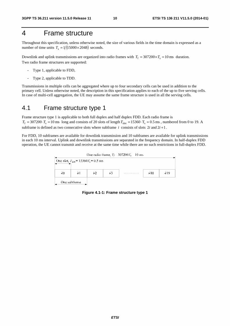
4.1 Frame structure type 1 Frame structure type 1 is applicable to both full duplex and half duplex FDD. Each radio frame is
ms 10307200 sf =⋅= TT long and consists of 20 slots of length ms 5.0T15360 sslot =⋅=T , numbered from 0 to 19. A
subframe is defined as two consecutive slots where subframe i consists of slots i2 and 12 +i .
For FDD, 10 subframes are available for downlink transmission and 10 subframes are available for uplink transmissions in each 10 ms interval. Uplink and downlink transmissions are separated in the frequency domain. In half-duplex FDD operation, the UE cannot transmit and receive at the same time while there are no such restrictions in full-duplex FDD.
Figure 4.1-1: Frame structure type 1
ETSI
ETSI TS 136 211 V11.5.0 (2014-01)113GPP TS 36.211 version 11.5.0 Release 11
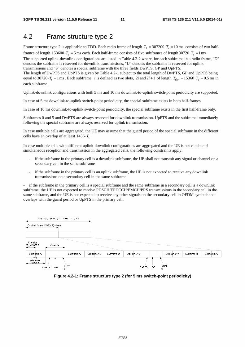
4.2 Frame structure type 2 Frame structure type 2 is applicable to TDD. Each radio frame of length ms 10307200 sf =⋅= TT consists of two half-
frames of length ms 5153600 s =⋅T each. Each half-frame consists of five subframes of length ms 107203 s =⋅T .
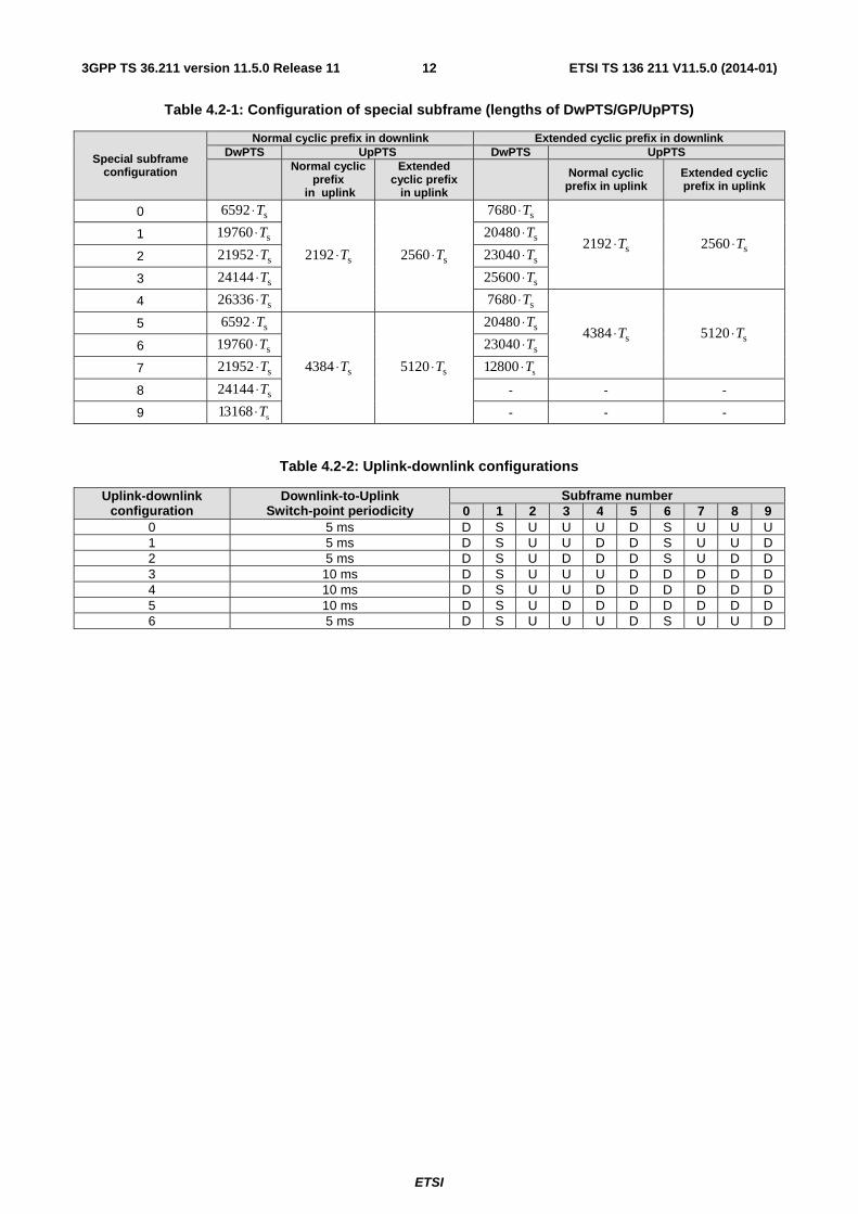
The supported uplink-downlink configurations are listed in Table 4.2-2 where, for each subframe in a radio frame, "D" denotes the subframe is reserved for downlink transmissions, "U" denotes the subframe is reserved for uplink transmissions and "S" denotes a special subframe with the three fields DwPTS, GP and UpPTS. The length of DwPTS and UpPTS is given by Table 4.2-1 subject to the total length of DwPTS, GP and UpPTS being equal to ms 107203 s =⋅T . Each subframe i is defined as two slots, i2 and 12 +i of length ms 5.015360 sslot =⋅= TT in
each subframe.
Uplink-downlink configurations with both 5 ms and 10 ms downlink-to-uplink switch-point periodicity are supported.
In case of 5 ms downlink-to-uplink switch-point periodicity, the special subframe exists in both half-frames.
In case of 10 ms downlink-to-uplink switch-point periodicity, the special subframe exists in the first half-frame only.
Subframes 0 and 5 and DwPTS are always reserved for downlink transmission. UpPTS and the subframe immediately following the special subframe are always reserved for uplink transmission.
In case multiple cells are aggregated, the UE may assume that the guard period of the special subframe in the different cells have an overlap of at least s1456 T⋅ .
In case multiple cells with different uplink-downlink configurations are aggregated and the UE is not capable of simultaneous reception and transmission in the aggregated cells, the following constraints apply:
- if the subframe in the primary cell is a downlink subframe, the UE shall not transmit any signal or channel on a secondary cell in the same subframe
- if the subframe in the primary cell is an uplink subframe, the UE is not expected to receive any downlink transmissions on a secondary cell in the same subframe
- if the subframe in the primary cell is a special subframe and the same subframe in a secondary cell is a downlink subframe, the UE is not expected to receive PDSCH/EPDCCH/PMCH/PRS transmissions in the secondary cell in the same subframe, and the UE is not expected to receive any other signals on the secondary cell in OFDM symbols that overlaps with the guard period or UpPTS in the primary cell.
Figure 4.2-1: Frame structure type 2 (for 5 ms switch-point periodicity)
ETSI
ETSI TS 136 211 V11.5.0 (2014-01)123GPP TS 36.211 version 11.5.0 Release 11
Table 4.2-1: Configuration of special subframe (lengths of DwPTS/GP/UpPTS)
Special subframe configuration
Normal cyclic prefix in downlink Extended cyclic prefix in downlink DwPTS UpPTS DwPTS UpPTS
Normal cyclic
prefix in uplink
Extended cyclic prefix
in uplink Normal cyclic
prefix in uplink Extended cyclic prefix in uplink
0 s6592 T⋅
s2192 T⋅ s2560 T⋅
s7680 T⋅
s2192 T⋅ s2560 T⋅ 1 s19760 T⋅ s20480 T⋅
2 s21952 T⋅ s23040 T⋅
3 s24144 T⋅ s25600 T⋅
4 s26336 T⋅ s7680 T⋅
s4384 T⋅ s5120 T⋅ 5 s6592 T⋅
s4384 T⋅ s5120 T⋅
s20480 T⋅
6 s19760 T⋅ s23040 T⋅
7 s21952 T⋅ s12800 T⋅
8 s24144 T⋅ - - -
9 s13168 T⋅ - - -
Table 4.2-2: Uplink-downlink configurations
Uplink-downlink configuration
Downlink-to-Uplink Switch-point periodicity
Subframe number 0 1 2 3 4 5 6 7 8 9
0 5 ms D S U U U D S U U U 1 5 ms D S U U D D S U U D 2 5 ms D S U D D D S U D D 3 10 ms D S U U U D D D D D 4 10 ms D S U U D D D D D D 5 10 ms D S U D D D D D D D 6 5 ms D S U U U D S U U D
ETSI
ETSI TS 136 211 V11.5.0 (2014-01)133GPP TS 36.211 version 11.5.0 Release 11
5 Uplink
5.1 Overview The smallest resource unit for uplink transmissions is denoted a resource element and is defined in clause 5.2.2.
5.1.1 Physical channels
An uplink physical channel corresponds to a set of resource elements carrying information originating from higher layers and is the interface defined between 3GPP TS 36.212 [3] and the present document 3GPP TS 36.211. The following uplink physical channels are defined:
- Physical Uplink Shared Channel, PUSCH
- Physical Uplink Control Channel, PUCCH
- Physical Random Access Channel, PRACH
5.1.2 Physical signals
An uplink physical signal is used by the physical layer but does not carry information originating from higher layers. The following uplink physical signals are defined:
- Reference signal
5.2 Slot structure and physical resources
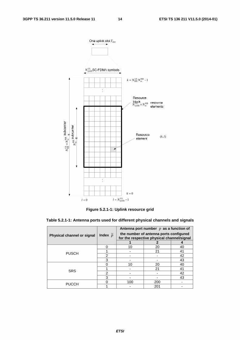
5.2.1 Resource grid
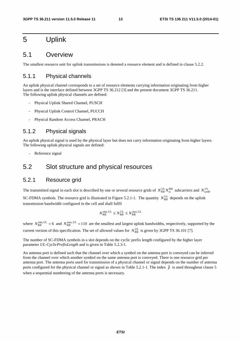
The transmitted signal in each slot is described by one or several resource grids of RBsc
ULRB NN subcarriers and UL
symbN
SC-FDMA symbols. The resource grid is illustrated in Figure 5.2.1-1. The quantity ULRBN depends on the uplink
transmission bandwidth configured in the cell and shall fulfil
ULmax,RB
ULRB
ULmin,RB NNN ≤≤
where 6ULmin,RB =N and 110ULmax,
RB =N are the smallest and largest uplink bandwidths, respectively, supported by the
current version of this specification. The set of allowed values for ULRBN is given by 3GPP TS 36.101 [7].
The number of SC-FDMA symbols in a slot depends on the cyclic prefix length configured by the higher layer parameter UL-CyclicPrefixLength and is given in Table 5.2.3-1.
An antenna port is defined such that the channel over which a symbol on the antenna port is conveyed can be inferred from the channel over which another symbol on the same antenna port is conveyed. There is one resource grid per antenna port. The antenna ports used for transmission of a physical channel or signal depends on the number of antenna ports configured for the physical channel or signal as shown in Table 5.2.1-1. The index p~ is used throughout clause 5
when a sequential numbering of the antenna ports is necessary.
ETSI
ETSI TS 136 211 V11.5.0 (2014-01)143GPP TS 36.211 version 11.5.0 Release 11
ULsymbN
slotT
0=l 1ULsymb −= Nl
RB
scU
LR
BN
N×
RB
scN
RBsc
ULsymb NN ×
),( lk
0=k
1RBsc
ULRB −= NNk
Figure 5.2.1-1: Uplink resource grid
Table 5.2.1-1: Antenna ports used for different physical channels and signals
Physical channel or signal Index p~
Antenna port number p as a function of the number of antenna ports configured
for the respective physical channel/signal 1 2 4
PUSCH
0 10 20 40 1 - 21 41 2 - - 42 3 - - 43
SRS
0 10 20 40 1 - 21 41 2 - - 42 3 - - 43
PUCCH 0 100 200 - 1 - 201 -
ETSI
ETSI TS 136 211 V11.5.0 (2014-01)153GPP TS 36.211 version 11.5.0 Release 11
5.2.2 Resource elements
Each element in the resource grid is called a resource element and is uniquely defined by the index pair ( )lk, in a slot
where 1,...,0 RBsc
ULRB −= NNk and 1,...,0 UL
symb −= Nl are the indices in the frequency and time domains, respectively.
Resource element ( )lk, on antenna port p corresponds to the complex value )(,plka .
When there is no risk for confusion, or no particular antenna port is specified, the index p may be dropped.
Quantities )(,plka corresponding to resource elements not used for transmission of a physical channel or a physical signal
in a slot shall be set to zero.
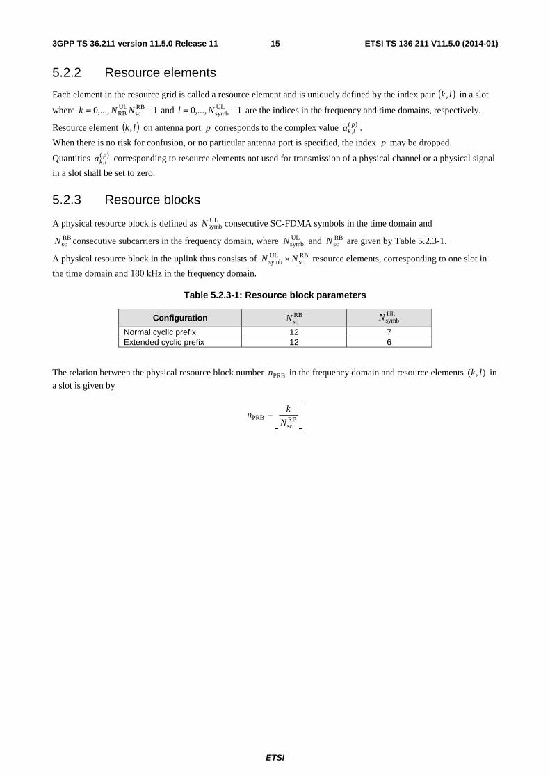
5.2.3 Resource blocks
A physical resource block is defined as ULsymbN consecutive SC-FDMA symbols in the time domain and
RBscN consecutive subcarriers in the frequency domain, where UL
symbN and RBscN are given by Table 5.2.3-1.
A physical resource block in the uplink thus consists of RBsc
ULsymb NN × resource elements, corresponding to one slot in
the time domain and 180 kHz in the frequency domain.
Table 5.2.3-1: Resource block parameters
Configuration RBscN
ULsymbN
Normal cyclic prefix 12 7 Extended cyclic prefix 12 6
The relation between the physical resource block number PRBn in the frequency domain and resource elements ),( lk in
a slot is given by
⎥⎥⎦
⎥
⎢⎢⎣
⎢=
RBsc
PRBN
kn
ETSI
ETSI TS 136 211 V11.5.0 (2014-01)163GPP TS 36.211 version 11.5.0 Release 11
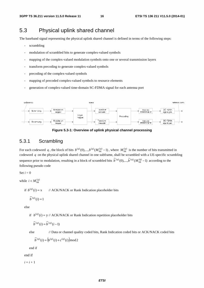
5.3 Physical uplink shared channel The baseband signal representing the physical uplink shared channel is defined in terms of the following steps:
- scrambling
- modulation of scrambled bits to generate complex-valued symbols
- mapping of the complex-valued modulation symbols onto one or several transmission layers
- transform precoding to generate complex-valued symbols
- precoding of the complex-valued symbols
- mapping of precoded complex-valued symbols to resource elements
- generation of complex-valued time-domain SC-FDMA signal for each antenna port
Figure 5.3-1: Overview of uplink physical channel processing
5.3.1 Scrambling
For each codeword q , the block of bits )1(),...,0( )(bit
)()( −qqq Mbb , where )(bitqM is the number of bits transmitted in
codeword q on the physical uplink shared channel in one subframe, shall be scrambled with a UE-specific scrambling
sequence prior to modulation, resulting in a block of scrambled bits )1(~
),...,0(~ (q)
bit)()( −Mbb qq according to the
following pseudo code
Set i = 0
while )(bitqMi <
if x)()( =ib q // ACK/NACK or Rank Indication placeholder bits
1)(~ )( =ib q
else
if y)()( =ib q // ACK/NACK or Rank Indication repetition placeholder bits
)1(~
)(~ )()( −= ibib qq
else // Data or channel quality coded bits, Rank Indication coded bits or ACK/NACK coded bits
( ) 2mod)()()(~ )()()( icibib qqq +=
end if
end if
i = i + 1
ETSI
ETSI TS 136 211 V11.5.0 (2014-01)173GPP TS 36.211 version 11.5.0 Release 11
end while
where x and y are tags defined in 3GPP TS 36.212 [3] clause 5.2.2.6 and where the scrambling sequence )()( ic q is
given by clause 7.2. The scrambling sequence generator shall be initialised with
⎣ ⎦ cellID
9s
1314RNTIinit 2222 Nnqnc +⋅+⋅+⋅= at the start of each subframe where RNTIn corresponds to the RNTI
associated with the PUSCH transmission as described in clause 8 in 3GPP TS 36.213 [4].
Up to two codewords can be transmitted in one subframe, i.e., { }1,0∈q . In the case of single-codeword transmission,
0=q .
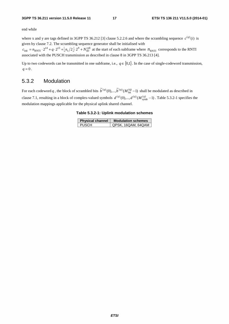
5.3.2 Modulation
For each codeword q , the block of scrambled bits )1(~
),...,0(~ (q)
bit)()( −Mbb qq shall be modulated as described in
clause 7.1, resulting in a block of complex-valued symbols )1(),...,0( )(symb
)()( −qqq Mdd . Table 5.3.2-1 specifies the
modulation mappings applicable for the physical uplink shared channel.
Table 5.3.2-1: Uplink modulation schemes
Physical channel Modulation schemes PUSCH QPSK, 16QAM, 64QAM
ETSI
ETSI TS 136 211 V11.5.0 (2014-01)183GPP TS 36.211 version 11.5.0 Release 11
5.3.2A Layer mapping
The complex-valued modulation symbols for each of the codewords to be transmitted are mapped onto one or two
layers. Complex-valued modulation symbols )1(),...,0( )(symb
)()( −qqq Mdd for codeword q shall be mapped onto the
layers [ ]Tixixix )(...)()( )1()0( −= υ , 1,...,1,0 layersymb −= Mi where υ is the number of layers and layer
symbM is the number of
modulation symbols per layer.
5.3.2A.1 Layer mapping for transmission on a single antenna port
For transmission on a single antenna port, a single layer is used, 1=υ , and the mapping is defined by
)()( )0()0( idix =
with (0)symb
layersymb MM = .
5.3.2A.2 Layer mapping for spatial multiplexing
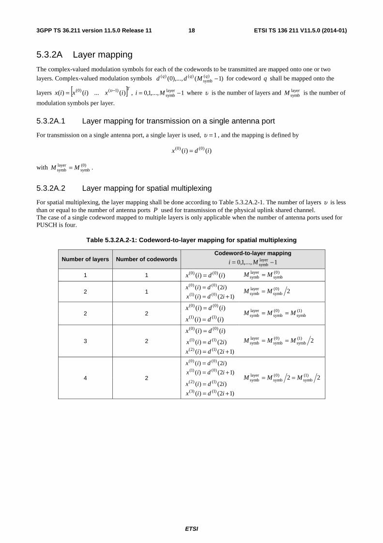
For spatial multiplexing, the layer mapping shall be done according to Table 5.3.2A.2-1. The number of layers υ is less than or equal to the number of antenna ports P used for transmission of the physical uplink shared channel. The case of a single codeword mapped to multiple layers is only applicable when the number of antenna ports used for PUSCH is four.
Table 5.3.2A.2-1: Codeword-to-layer mapping for spatial multiplexing
Number of layers Number of codewords Codeword-to-layer mapping
1,...,1,0 layersymb −= Mi
1 1 )()( )0()0( idix = )0(
symblayersymb MM =
2 1 )12()(
)2()()0()1(
)0()0(
+==
idix
idix 2)0(
symblayersymb MM =
2 2 )()( )0()0( idix = )1(
symb)0(
symblayersymb MMM ==
)()( )1()1( idix =
3 2
)()( )0()0( idix =
)12()(
)2()()1()2(
)1()1(
+==
idix
idix
2)1(symb
)0(symb
layersymb MMM ==
4 2 )12()(
)2()()0()1(
)0()0(
+==
idix
idix
22 )1(symb
)0(symb
layersymb MMM ==
)12()(
)2()()1()3(
)1()2(
+==
idix
idix
ETSI
ETSI TS 136 211 V11.5.0 (2014-01)193GPP TS 36.211 version 11.5.0 Release 11
5.3.3 Transform precoding
For each layer 1,...,1,0 −= υλ the block of complex-valued symbols )1(),...,0( layersymb
)()( −Mxx λλ is divided into
PUSCHsc
layersymb MM sets, each corresponding to one SC-FDMA symbol. Transform precoding shall be applied according
to
1,...,0
1,...,0
)(1
)(
PUSCHsc
layersymb
PUSCHsc
1
0
2
PUSCHsc
)(
PUSCHsc
PUSCHsc
)(
PUSCHsc
PUSCHsc
−=
−=
+⋅=+⋅ ∑−
=
−
MMl
Mk
eiMlxM
kMlyM
i
M
ikj
πλλ
resulting in a block of complex-valued symbols )1(),...,0( layersymb
)()( −Myy λλ . The variable RBsc
PUSCHRB
PUSCHsc NMM ⋅= ,
where PUSCHRBM represents the bandwidth of the PUSCH in terms of resource blocks, and shall fulfil
ULRB
PUSCHRB
532 532 NM ≤⋅⋅= ααα
where 532 ,, ααα is a set of non-negative integers.
5.3.3A Precoding
The precoder takes as input a block of vectors [ ]Tiyiy )(...)( )1()0( −υ , 1,...,1,0 layersymb −= Mi from the transform
precoder and generates a block of vectors [ ]TP iziz )()( )1()0( −K , 1,...,1,0 ap
symb −= Mi to be mapped onto resource
elements.
5.3.3A.1 Precoding for transmission on a single antenna port
For transmission on a single antenna port, precoding is defined by
)()( )0()0( iyiz =
where 1,...,1,0 apsymb −= Mi , layer
symbapsymb MM = .
5.3.3A.2 Precoding for spatial multiplexing
Precoding for spatial multiplexing is only used in combination with layer mapping for spatial multiplexing as described in clause 5.3.2A.2. Spatial multiplexing supports 2=P or 4=P antenna ports where the set of antenna ports used for spatial multiplexing is { }21,20∈p and { }43,42,41,40∈p , respectively.
Precoding for spatial multiplexing is defined by
⎥⎥⎥
⎦
⎤
⎢⎢⎢
⎣
⎡
=⎥⎥⎥
⎦
⎤
⎢⎢⎢
⎣
⎡
−− )(
)(
)(
)(
)1(
)0(
)1(
)0(
iy
iy
W
iz
iz
P υMM
where 1,...,1,0 apsymb −= Mi , layer
symbapsymb MM = .
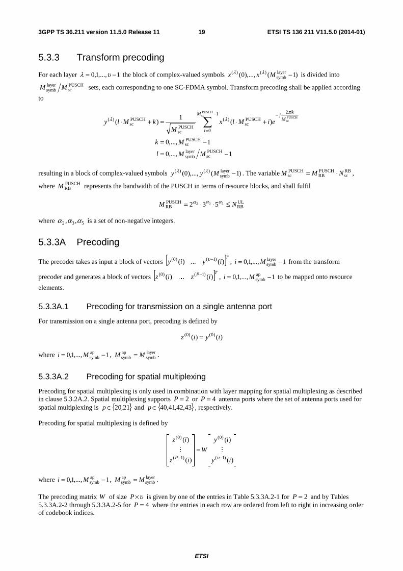
The precoding matrix W of size υ×P is given by one of the entries in Table 5.3.3A.2-1 for 2=P and by Tables 5.3.3A.2-2 through 5.3.3A.2-5 for 4=P where the entries in each row are ordered from left to right in increasing order of codebook indices.
ETSI
ETSI TS 136 211 V11.5.0 (2014-01)203GPP TS 36.211 version 11.5.0 Release 11
Table 5.3.3A.2-1: Codebook for transmission on antenna ports { }21,20
Codebook index Number of layers
1=υ 2=υ
0 ⎥⎦
⎤⎢⎣
⎡
1
1
2
1 ⎥
⎦
⎤⎢⎣
⎡
10
01
2
1
1 ⎥⎦
⎤⎢⎣
⎡
−1
1
2
1 -
2 ⎥⎦
⎤⎢⎣
⎡
j
1
2
1 -
3 ⎥⎦
⎤⎢⎣
⎡
− j
1
2
1 -
4 ⎥⎦
⎤⎢⎣
⎡
0
1
2
1 -
5 ⎥⎦
⎤⎢⎣
⎡
1
0
2
1 -
Table 5.3.3A.2-2: Codebook for transmission on antenna ports { }43,42,41,40 with 1=υ
Codebook index Number of layers 1=υ
0 – 7
⎥⎥⎥⎥
⎦
⎤
⎢⎢⎢⎢
⎣
⎡
−1
1
1
1
2
1
⎥⎥⎥⎥
⎦
⎤
⎢⎢⎢⎢
⎣
⎡
j
j
1
1
2
1
⎥⎥⎥⎥
⎦
⎤
⎢⎢⎢⎢
⎣
⎡
−1
1
1
1
2
1
⎥⎥⎥⎥
⎦
⎤
⎢⎢⎢⎢
⎣
⎡
−−
j
j
1
1
2
1
⎥⎥⎥⎥
⎦
⎤
⎢⎢⎢⎢
⎣
⎡
j
j
1
1
2
1
⎥⎥⎥⎥
⎦
⎤
⎢⎢⎢⎢
⎣
⎡
1
1
2
1
j
j
⎥⎥⎥⎥
⎦
⎤
⎢⎢⎢⎢
⎣
⎡
−−
j
j
1
1
2
1
⎥⎥⎥⎥
⎦
⎤
⎢⎢⎢⎢
⎣
⎡
−−
1
1
2
1
j
j
8 – 15
⎥⎥⎥⎥
⎦
⎤
⎢⎢⎢⎢
⎣
⎡
−
1
1
1
1
2
1
⎥⎥⎥⎥
⎦
⎤
⎢⎢⎢⎢
⎣
⎡
−
−
j
j
1
1
2
1
⎥⎥⎥⎥
⎦
⎤
⎢⎢⎢⎢
⎣
⎡
−−−
1
1
1
1
2
1
⎥⎥⎥⎥
⎦
⎤
⎢⎢⎢⎢
⎣
⎡
−−
j
j
1
1
2
1
⎥⎥⎥⎥
⎦
⎤
⎢⎢⎢⎢
⎣
⎡
−
−
j
j
1
1
2
1
⎥⎥⎥⎥
⎦
⎤
⎢⎢⎢⎢
⎣
⎡
−
−
1
1
2
1
j
j
⎥⎥⎥⎥
⎦
⎤
⎢⎢⎢⎢
⎣
⎡
−−
j
j
1
1
2
1
⎥⎥⎥⎥
⎦
⎤
⎢⎢⎢⎢
⎣
⎡
−−
1
1
2
1
j
j
16 – 23
⎥⎥⎥⎥
⎦
⎤
⎢⎢⎢⎢
⎣
⎡
0
1
0
1
2
1
⎥⎥⎥⎥
⎦
⎤
⎢⎢⎢⎢
⎣
⎡
−0
1
0
1
2
1
⎥⎥⎥⎥
⎦
⎤
⎢⎢⎢⎢
⎣
⎡
0
0
1
2
1
j
⎥⎥⎥⎥
⎦
⎤
⎢⎢⎢⎢
⎣
⎡
−0
0
1
2
1
j
⎥⎥⎥⎥
⎦
⎤
⎢⎢⎢⎢
⎣
⎡
1
0
1
0
2
1
⎥⎥⎥⎥
⎦
⎤
⎢⎢⎢⎢
⎣
⎡
−1
0
1
0
2
1
⎥⎥⎥⎥
⎦
⎤
⎢⎢⎢⎢
⎣
⎡
j
0
1
0
2
1
⎥⎥⎥⎥
⎦
⎤
⎢⎢⎢⎢
⎣
⎡
− j
0
1
0
2
1
ETSI
ETSI TS 136 211 V11.5.0 (2014-01)213GPP TS 36.211 version 11.5.0 Release 11
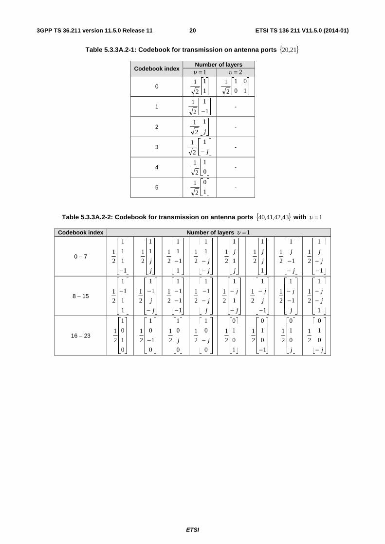
Table 5.3.3A.2-3: Codebook for transmission on antenna ports { }43,42,41,40 with 2=υ
Codebook index Number of layers 2=υ
0 – 3
⎥⎥⎥⎥
⎦
⎤
⎢⎢⎢⎢
⎣
⎡
− j0
10
01
01
2
1
⎥⎥⎥⎥
⎦
⎤
⎢⎢⎢⎢
⎣
⎡
j0
10
01
01
2
1
⎥⎥⎥⎥
⎦
⎤
⎢⎢⎢⎢
⎣
⎡
−
10
10
0
01
2
1 j
⎥⎥⎥⎥
⎦
⎤
⎢⎢⎢⎢
⎣
⎡
−
−
10
10
0
01
2
1 j
4 – 7
⎥⎥⎥⎥
⎦
⎤
⎢⎢⎢⎢
⎣
⎡
−
−
j0
10
01
01
2
1
⎥⎥⎥⎥
⎦
⎤
⎢⎢⎢⎢
⎣
⎡
−
j0
10
01
01
2
1
⎥⎥⎥⎥
⎦
⎤
⎢⎢⎢⎢
⎣
⎡
10
10
0
01
2
1 j
⎥⎥⎥⎥
⎦
⎤
⎢⎢⎢⎢
⎣
⎡
−10
10
0
01
2
1 j
8 – 11
⎥⎥⎥⎥
⎦
⎤
⎢⎢⎢⎢
⎣
⎡
10
01
10
01
2
1
⎥⎥⎥⎥
⎦
⎤
⎢⎢⎢⎢
⎣
⎡
−10
01
10
01
2
1
⎥⎥⎥⎥
⎦
⎤
⎢⎢⎢⎢
⎣
⎡
−10
01
10
01
2
1
⎥⎥⎥⎥
⎦
⎤
⎢⎢⎢⎢
⎣
⎡
−−
10
01
10
01
2
1
12 – 15
⎥⎥⎥⎥
⎦
⎤
⎢⎢⎢⎢
⎣
⎡
01
10
10
01
2
1
⎥⎥⎥⎥
⎦
⎤
⎢⎢⎢⎢
⎣
⎡
−01
10
10
01
2
1
⎥⎥⎥⎥
⎦
⎤
⎢⎢⎢⎢
⎣
⎡
− 01
10
10
01
2
1
⎥⎥⎥⎥
⎦
⎤
⎢⎢⎢⎢
⎣
⎡
−−01
10
10
01
2
1
Table 5.3.3A.2-4: Codebook for transmission on antenna ports { }43,42,41,40 with 3=υ
Codebook index Number of layers 3=υ
0 – 3
⎥⎥⎥⎥
⎦
⎤
⎢⎢⎢⎢
⎣
⎡
100
010
001
001
2
1
⎥⎥⎥⎥
⎦
⎤
⎢⎢⎢⎢
⎣
⎡
−
100
010
001
001
2
1
⎥⎥⎥⎥
⎦
⎤
⎢⎢⎢⎢
⎣
⎡
100
001
010
001
2
1
⎥⎥⎥⎥
⎦
⎤
⎢⎢⎢⎢
⎣
⎡
−100
001
010
001
2
1
4 – 7
⎥⎥⎥⎥
⎦
⎤
⎢⎢⎢⎢
⎣
⎡
001
100
010
001
2
1
⎥⎥⎥⎥
⎦
⎤
⎢⎢⎢⎢
⎣
⎡
− 001
100
010
001
2
1
⎥⎥⎥⎥
⎦
⎤
⎢⎢⎢⎢
⎣
⎡
100
001
001
010
2
1
⎥⎥⎥⎥
⎦
⎤
⎢⎢⎢⎢
⎣
⎡
−100
001
001
010
2
1
8 – 11
⎥⎥⎥⎥
⎦
⎤
⎢⎢⎢⎢
⎣
⎡
001
100
001
010
2
1
⎥⎥⎥⎥
⎦
⎤
⎢⎢⎢⎢
⎣
⎡
− 001
100
001
010
2
1
⎥⎥⎥⎥
⎦
⎤
⎢⎢⎢⎢
⎣
⎡
001
001
100
010
2
1
⎥⎥⎥⎥
⎦
⎤
⎢⎢⎢⎢
⎣
⎡
− 001
001
100
010
2
1
Table 5.3.3A.2-5: Codebook for transmission on antenna ports { }43,42,41,40 with 4=υ
Codebook index Number of layers 4=υ
0
⎥⎥⎥⎥
⎦
⎤
⎢⎢⎢⎢
⎣
⎡
1000
0100
0010
0001
2
1

ETSI
ETSI TS 136 211 V11.5.0 (2014-01)223GPP TS 36.211 version 11.5.0 Release 11
5.3.4 Mapping to physical resources
For each antenna port p used for transmission of the PUSCH in a subframe the block of complex-valued symbols
)1(),...,0( apsymb
)~()~( −Mzz pp shall be multiplied with the amplitude scaling factor PUSCHβ in order to conform to the
transmit power PUSCHP specified in clause 5.1.1.1 in 3GPP TS 36.213 [4], and mapped in sequence starting with
)0()~( pz to physical resource blocks on antenna port p and assigned for transmission of PUSCH. The relation between
the index p~ and the antenna port number p is given by Table 5.2.1-1. The mapping to resource elements ( )lk,
corresponding to the physical resource blocks assigned for transmission and
- not used for transmission of reference signals, and
- not part of the last SC-FDMA symbol in a subframe, if the UE transmits SRS in the same subframe, and
- not part of the last SC-FDMA symbol in a subframe configured with cell-specific SRS, if the PUSCH transmission partly or fully overlaps with the cell-specific SRS bandwidth, and
- not part of an SC-FDMA symbol reserved for possible SRS transmission in a UE-specific aperiodic SRS subframe, and
- not part of an SC-FDMA symbol reserved for possible SRS transmission in a UE-specific periodic SRS subframe in the same serving cell when the UE is configured with multiple TAGs
shall be in increasing order of first the index k , then the index l , starting with the first slot in the subframe.
If uplink frequency-hopping is disabled or the resource blocks allocated for PUSCH transmission are not contiguous in frequency, the set of physical resource blocks to be used for transmission is given by VRBPRB nn = where VRBn is
obtained from the uplink scheduling grant as described in clause 8.1 in 3GPP TS 36.213 [4].
If uplink frequency-hopping with type 1 PUSCH hopping is enabled, the set of physical resource blocks to be used for transmission is given by clause 8.4.1 in 3GPP TS 36.213 [4].
If uplink frequency-hopping with predefined hopping pattern is enabled, the set of physical resource blocks to be used for transmission in slot sn is given by the scheduling grant together with a predefined pattern according to
( ) ( ) ( )( )( )⎣ ⎦
⎡ ⎤
⎡ ⎤⎪⎩
⎪⎨⎧
>−
==
⎪⎩
⎪⎨⎧
>+
==
⎩⎨⎧
−−
=
⋅⋅−−+⋅+=
12
1~
12)(~1)(~
)(
hopping subframeinter and intra
hopping subframeinter2
)mod()(mod~21~)(~
HORBVRB
VRBVRB
HORBsPRB
sPRBsPRB
s
s
sbsbRBm
sbRBVRB
sbRB
sbRBhopVRBsPRB
sb
sb
sb
sb
NNn
Nnn
NNnn
Nnnnn
n
ni
NNifNnNNifnnn
where VRBn is obtained from the scheduling grant as described in clause 8.1 in 3GPP TS 36.213 [4]. The parameter
pusch-HoppingOffset, HORBN , is provided by higher layers. The size sb
RBN of each sub-band is given by,
( )⎣ ⎦⎪⎩
⎪⎨⎧
>−−
==
12mod
1
sbsbHORB
HORB
ULRB
sbULRBsb
RBNNNNN
NNN
where the number of sub-bands sbN is given by higher layers. The function { }1,0)(m ∈if determines whether mirroring
is used or not. The parameter Hopping-mode provided by higher layers determines if hopping is "inter-subframe" or "intra and inter-subframe".
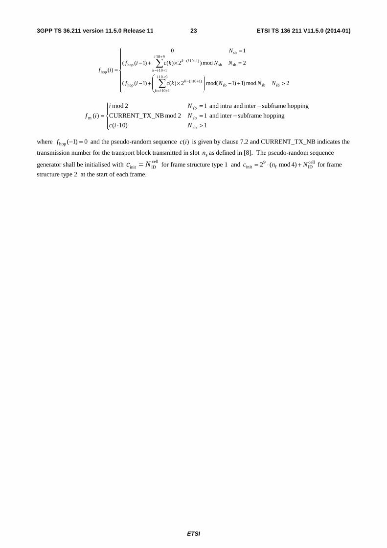
The hopping function )(hop if and the function )(m if are given by
ETSI
ETSI TS 136 211 V11.5.0 (2014-01)233GPP TS 36.211 version 11.5.0 Release 11
⎪⎪⎪
⎩
⎪⎪⎪
⎨
⎧
>+−⎟⎟
⎠
⎞
⎜⎜
⎝
⎛×+−
=×+−
=
=
∑
∑
+⋅
+⋅=
+⋅−
+⋅
+⋅=
+⋅−
2mod)1)1mod(2)()1((
2mod)2)()1((
10
)(
sbsbsb
910
110
)110(hop
sbsb
910
110
)110(hop
sb
hop
NNNkcif
NNkcif
N
ifi
ik
ik
i
ik
ik
⎪⎩
⎪⎨
⎧
>⋅−=
−==
1)10(
hopping subframeinter and 12mod_NBCURRENT_TX
hopping subframeinter and intra and 12mod
)(
sb
sb
sb
m
Nic
N
Ni
if
where 0)1(hop =−f and the pseudo-random sequence )(ic is given by clause 7.2 and CURRENT_TX_NB indicates the
transmission number for the transport block transmitted in slot sn as defined in [8]. The pseudo-random sequence
generator shall be initialised with cellIDinit Nc = for frame structure type 1 and cell
IDf9
init )4mod(2 Nnc +⋅= for frame
structure type 2
at the start of each frame.

ETSI
ETSI TS 136 211 V11.5.0 (2014-01)243GPP TS 36.211 version 11.5.0 Release 11
5.4 Physical uplink control channel The physical uplink control channel, PUCCH, carries uplink control information. Simultaneous transmission of PUCCH and PUSCH from the same UE is supported if enabled by higher layers. For frame structure type 2, the PUCCH is not transmitted in the UpPTS field.
The physical uplink control channel supports multiple formats as shown in Table 5.4-1. Formats 2a and 2b are supported for normal cyclic prefix only.
Table 5.4-1: Supported PUCCH formats
PUCCH format Modulation scheme Number of bits per subframe, bitM
1 N/A N/A 1a BPSK 1 1b QPSK 2 2 QPSK 20 2a QPSK+BPSK 21 2b QPSK+QPSK 22 3 QPSK 48
All PUCCH formats use a cyclic shift, ),( scellcs lnn , which varies with the symbol number l and the slot number sn
according to
∑ = ⋅++⋅= 7
0 sULsymbs
cellcs 2)88(),(
iiilnNclnn
where the pseudo-random sequence )(ic is defined by clause 7.2. The pseudo-random sequence generator shall be
initialized with RSIDinit nc = , where RS
IDn is given by clause 5.5.1.5 with cellIDN corresponding to the primary cell, at the
beginning of each radio frame.
The physical resources used for PUCCH depends on two parameters, (2)RBN and (1)
csN , given by higher layers.
The variable 0(2)RB ≥N denotes the bandwidth in terms of resource blocks that are available for use by PUCCH formats
2/2a/2b transmission in each slot. The variable (1)csN denotes the number of cyclic shift used for PUCCH formats
1/1a/1b in a resource block used for a mix of formats 1/1a/1b and 2/2a/2b. The value of (1)csN is an integer multiple of
PUCCHshiftΔ within the range of {0, 1, …, 7}, where PUCCH
shiftΔ is provided by higher layers. No mixed resource block is
present if 0(1)cs =N . At most one resource block in each slot supports a mix of formats 1/1a/1b and 2/2a/2b.
Resources used for transmission of PUCCH formats 1/1a/1b, 2/2a/2b and 3 are represented by the non-negative indices
)~(1,PUCCH
pn , )2(8
(1)cs
RBsc
(1)csRB
sc(2)RB
)~(2,PUCCH −−⋅
⎥⎥⎥
⎤
⎢⎢⎢
⎡+< NN
NNNn p , and )~(3,
PUCCHpn , respectively.
5.4.1 PUCCH formats 1, 1a and 1b
For PUCCH format 1, information is carried by the presence/absence of transmission of PUCCH from the UE. In the remainder of this clause, 1)0( =d shall be assumed for PUCCH format 1.
For PUCCH formats 1a and 1b, one or two explicit bits are transmitted, respectively. The block of bits )1(),...,0( bit −Mbb shall be modulated as described in Table 5.4.1-1, resulting in a complex-valued symbol )0(d .
The modulation schemes for the different PUCCH formats are given by Table 5.4-1.
The complex-valued symbol )0(d shall be multiplied with a cyclically shifted length 12PUCCHseq =N sequence )(
)(,
~nr p
vuα
for each of the P antenna ports used for PUCCH transmission according to
1,...,1,0 ),()0(1
)( PUCCHseq
)(,
)~( ~ −=⋅= NnnrdP
ny pvu
p α
ETSI
ETSI TS 136 211 V11.5.0 (2014-01)253GPP TS 36.211 version 11.5.0 Release 11
where )()(
,~
nr pvu
α is defined by clause 5.5.1 with PUCCH
seqRSsc NM = . The antenna-port specific cyclic shift p~α varies
between symbols and slots as defined below.
The block of complex-valued symbols )1(),...,0( PUCCHseq
)~()~( −Nyy pp shall be scrambled by )( snS and block-wise
spread with the antenna-port specific orthogonal sequence )()~(oc
iw pn according to
( ) ( )nymwnSnNmNNmz pn
p )~(s
PUCCHseq
PUCCHseq
PUCCHSF
)~( )()(' )p~(oc
⋅⋅=+⋅+⋅⋅
where
1,0'
1,...,0
1,...,0PUCCHseq
PUCCHSF
=
−=
−=
m
Nn
Nm
and
⎩⎨⎧ =′
=otherwise
02mod)(if1)( 2
s~
s πjp
e
nnnS
with 4PUCCHSF =N for both slots of normal PUCCH formats 1/1a/1b, and 4PUCCH
SF =N for the first slot and
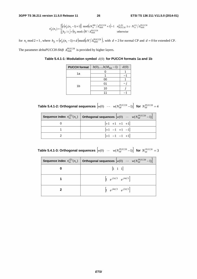
3PUCCHSF =N for the second slot of shortened PUCCH formats 1/1a/1b. The sequence )()~(
ociw pn
is given by Table 5.4.1-2
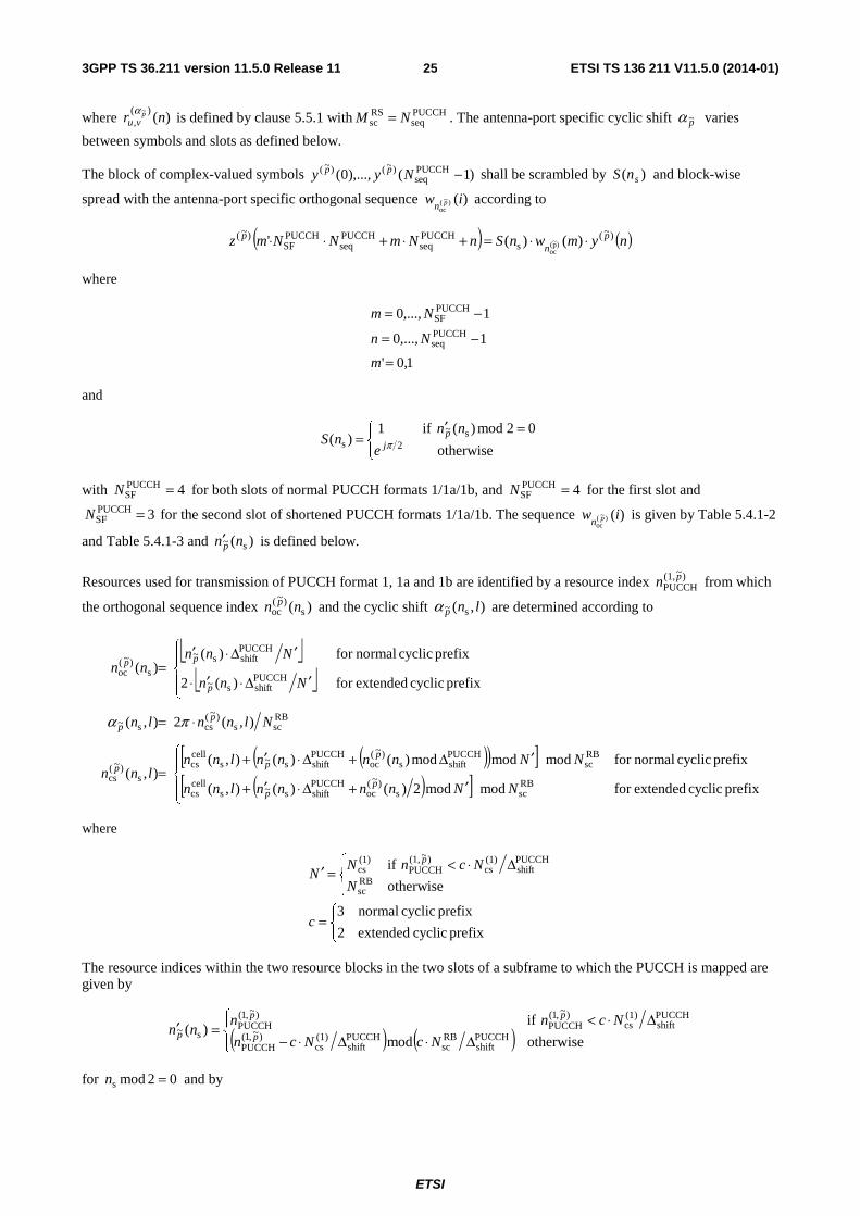
and Table 5.4.1-3 and )( s~ nnp′ is defined below.
Resources used for transmission of PUCCH format 1, 1a and 1b are identified by a resource index )~(1,PUCCH
pn from which
the orthogonal sequence index )( s)~(
oc nn p and the cyclic shift ),( s~ lnpα are determined according to
⎣ ⎦⎣ ⎦
( )( )[ ]( )[ ]⎪
⎩
⎪⎨
⎧
′+Δ⋅′+
′Δ+Δ⋅′+=
⋅=
⎪⎩
⎪⎨
⎧
′Δ⋅′⋅
′Δ⋅′=
prefix cyclic extendedfor modmod2)()(),(
prefix cyclic normalfor modmodmod)()(),(),(
),(2),(
prefix cyclic extendedfor )(2
prefix cyclic normalfor )()(
RBscs
)~(oc
PUCCHshifts~s
cellcs
RBsc
PUCCHshifts
)~(oc
PUCCHshifts~s
cellcs
s)~(
cs
RBscs
)~(css~
PUCCHshifts~
PUCCHshifts~
s)~(
oc
NNnnnnlnn
NNnnnnlnnlnn
Nlnnln
Nnn
Nnnnn
pp
ppp
pp
p
pp
πα
where
⎩⎨⎧
=
⎪⎩
⎪⎨⎧ Δ⋅<=′
prefix cyclic extended2
prefix cyclic normal3
otherwise
ifRBsc
PUCCHshift
(1)cs
)~(1,PUCCH
(1)cs
c
N
NcnNN
p
The resource indices within the two resource blocks in the two slots of a subframe to which the PUCCH is mapped are given by
( ) ( )⎪⎩
⎪⎨⎧
Δ⋅Δ⋅−Δ⋅<
=′otherwisemod
if)(
PUCCHshift
RBsc
PUCCHshift
(1)cs
)~,1(PUCCH
PUCCHshift
(1)cs
)~,1(PUCCH
)~,1(PUCCH
s~NcNcn
Ncnnnn
p
pp
p
for 02mods =n and by
ETSI
ETSI TS 136 211 V11.5.0 (2014-01)263GPP TS 36.211 version 11.5.0 Release 11
( )[ ] ( )⎣ ⎦ ( )⎪⎩
⎪⎨⎧
Δ+
Δ⋅≥−+Δ+−′=′
otherwise/'mod/
11mod1)1()(
PUCCHshift~~
PUCCHshift
(1)cs
)~,1(PUCCH
PUCCHshift
RBscs~
s~
Nchch
NcncNnncnn
pp
pp
p
for 12mods =n , where ( ) ( )PUCCHshifs~~ 'mod)1( tpp cNdnnh Δ+−′= , with 2=d for normal CP and 0=d for extended CP.
The parameter deltaPUCCH-Shift PUCCHshiftΔ is provided by higher layers.
Table 5.4.1-1: Modulation symbol )0(d for PUCCH formats 1a and 1b
PUCCH format )1(),...,0( bit −Mbb )0(d
1a 0 1 1 1−
1b
00 1 01 j−
10 j
11 1−
Table 5.4.1-2: Orthogonal sequences [ ])1()0( PUCCHSF −Nww L for 4PUCCH
SF =N
Sequence index )( s)~(
oc nn p Orthogonal sequences [ ])1()0( PUCCHSF −Nww L
0 [ ]1111 ++++ 1 [ ]1111 −+−+ 2 [ ]1111 +−−+
Table 5.4.1-3: Orthogonal sequences [ ])1()0( PUCCHSF −Nww L for 3PUCCH
SF =N
Sequence index )( s)~(
oc nn p Orthogonal sequences [ ])1()0( PUCCHSF −Nww L
0 [ ]111
1 [ ]34321 ππ jj ee
2 [ ]32341 ππ jj ee
ETSI
ETSI TS 136 211 V11.5.0 (2014-01)273GPP TS 36.211 version 11.5.0 Release 11
5.4.2 PUCCH formats 2, 2a and 2b
The block of bits )19(),...,0( bb shall be scrambled with a UE-specific scrambling sequence, resulting in a block of
scrambled bits )19(~
),...,0(~
bb according to
( ) 2mod)()()(~
icibib +=
where the scrambling sequence )(ic is given by clause 7.2. The scrambling sequence generator shall be initialised with
⎣ ⎦( ) ( ) RNTI16cell
IDsinit 21212 nNnc +⋅+⋅+= at the start of each subframe where RNTIn is C-RNTI.
The block of scrambled bits )19(~
),...,0(~
bb shall be QPSK modulated as described in clause 7.1, resulting in a block of
complex-valued modulation symbols )9(),...,0( dd .
Each complex-valued symbol )9(),...,0( dd shall be multiplied with a cyclically shifted length 12PUCCHseq =N sequence
)()(
,~
nr pvu
α for each of the P antenna ports used for PUCCH transmission according to
1,...,1,0
9,...,1,0
)()(1
)(
RBsc
)(,
PUCCHseq
)~( ~
−=
=
⋅=+⋅
Ni
n
irndP
inNz pvu
p α
where )()(
,~
ir pvu
α is defined by clause 5.5.1 with PUCCH
seqRSsc NM = .
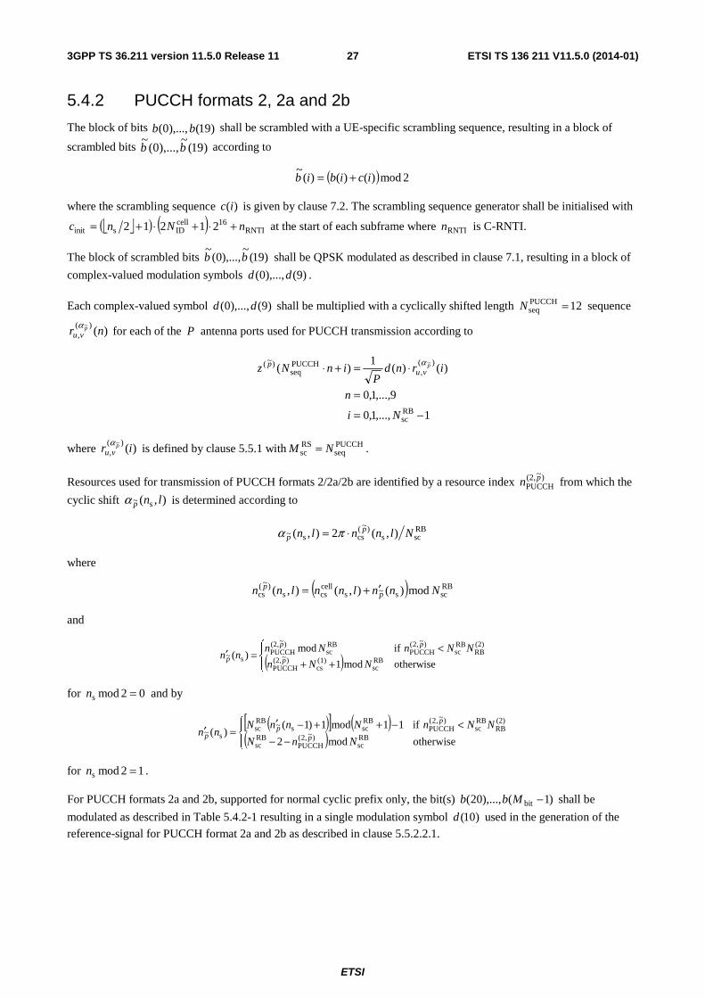
Resources used for transmission of PUCCH formats 2/2a/2b are identified by a resource index )~(2,PUCCH
pn from which the
cyclic shift ),( s~ lnpα is determined according to
RBscs
)~(css~ ),(2),( Nlnnln p
p ⋅= πα
where
( ) RBscs~s
cellcss
)~(cs mod)(),(),( Nnnlnnlnn p
p ′+=
and
( )⎪⎩
⎪⎨⎧
++<
=′otherwisemod1
ifmod)(
RBsc
(1)cs
)~(2,PUCCH
(2)RB
RBsc
)~,2(PUCCH
RBsc
)~(2,PUCCH
s~NNn
NNnNnnn
p
pp
p
for 02mods =n and by
( )[ ] ( )( )⎪⎩
⎪⎨⎧
−−<−++−′
=′otherwisemod2
if11mod1)1()(
RBsc
)~,2(PUCCH
RBsc
(2)RB
RBsc
)~,2(PUCCH
RBscs~
RBsc
s~NnN
NNnNnnNnn
p
pp
p
for 12mods =n .
For PUCCH formats 2a and 2b, supported for normal cyclic prefix only, the bit(s) )1(),...,20( bit −Mbb shall be
modulated as described in Table 5.4.2-1 resulting in a single modulation symbol )10(d used in the generation of the
reference-signal for PUCCH format 2a and 2b as described in clause 5.5.2.2.1.
ETSI
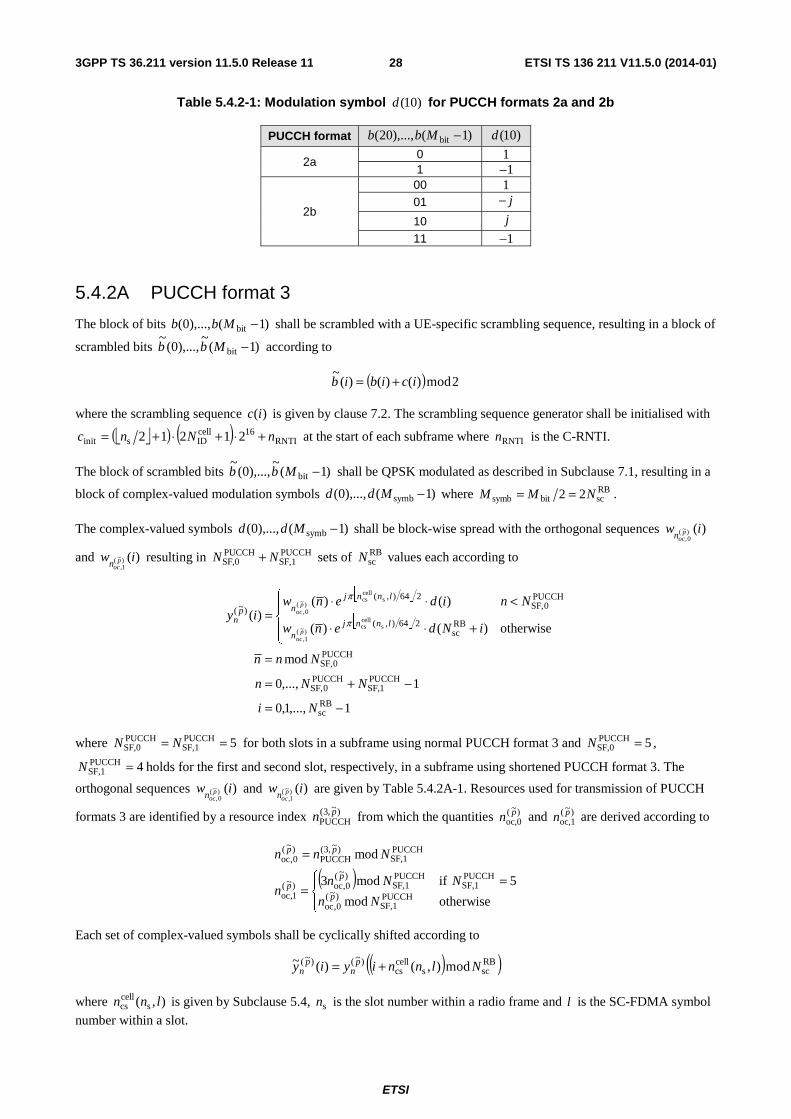
ETSI TS 136 211 V11.5.0 (2014-01)283GPP TS 36.211 version 11.5.0 Release 11
Table 5.4.2-1: Modulation symbol )10(d for PUCCH formats 2a and 2b
PUCCH format )1(),...,20( bit −Mbb )10(d
2a 0 1 1 1−
2b
00 1 01 j−
10 j
11 1−
5.4.2A PUCCH format 3
The block of bits )1(),...,0( bit −Mbb shall be scrambled with a UE-specific scrambling sequence, resulting in a block of
scrambled bits )1(~
),...,0(~
bit −Mbb according to
( ) 2mod)()()(~
icibib +=
where the scrambling sequence )(ic is given by clause 7.2. The scrambling sequence generator shall be initialised with
⎣ ⎦( ) ( ) RNTI16cell
IDsinit 21212 nNnc +⋅+⋅+= at the start of each subframe where RNTIn is the C-RNTI.
The block of scrambled bits )1(~
),...,0(~
bit −Mbb shall be QPSK modulated as described in Subclause 7.1, resulting in a
block of complex-valued modulation symbols )1(),...,0( symb −Mdd where RBscbitsymb 22 NMM == .
The complex-valued symbols )1(),...,0( symb −Mdd shall be block-wise spread with the orthogonal sequences )()~(0,
iw pocn
and )()~(1,
iw pocn
resulting in PUCCHSF,1
PUCCHSF,0 NN + sets of RB
scN values each according to
⎣ ⎦
⎣ ⎦
1,...,1,0
1,...,0
mod
otherwise)()(
)()()(
RBsc
PUCCH1SF,
PUCCH0SF,
PUCCH0SF,
RBsc
264),(
PUCCH0SF,
264),(
)~(
scellcs
)~(1,
scellcs
)~(0,
−=
−+=
=
⎪⎩
⎪⎨
⎧
+⋅⋅
<⋅⋅=
Ni
NNn
Nnn
iNdenw
Nnidenwiy
lnnjn
lnnjnp
np
oc
poc
π
π
where 5PUCCHSF,1
PUCCHSF,0 == NN for both slots in a subframe using normal PUCCH format 3 and 5PUCCH
SF,0 =N ,
4PUCCHSF,1 =N holds for the first and second slot, respectively, in a subframe using shortened PUCCH format 3. The
orthogonal sequences )()~(0,
iw pocn
and )()~(1,
iw pocn
are given by Table 5.4.2A-1. Resources used for transmission of PUCCH
formats 3 are identified by a resource index )~,3(PUCCH
pn from which the quantities )~(oc,0
pn and )~(oc,1
pn are derived according to
( )⎪⎩
⎪⎨⎧ =
=
=
otherwisemod
5 ifmod3
mod
PUCCHSF,1
)~(0,oc
PUCCHSF,1
PUCCHSF,1
)~(0,oc)~(
1,oc
PUCCHSF,1
)~,3(PUCCH
)~(0,oc
Nn
NNnn
Nnn
p
pp
pp
Each set of complex-valued symbols shall be cyclically shifted according to
( )( )RBscs
cellcs
)~()~( mod),()(~ Nlnniyiy pn
pn +=
where ),( scellcs lnn is given by Subclause 5.4, sn is the slot number within a radio frame and l is the SC-FDMA symbol
number within a slot.
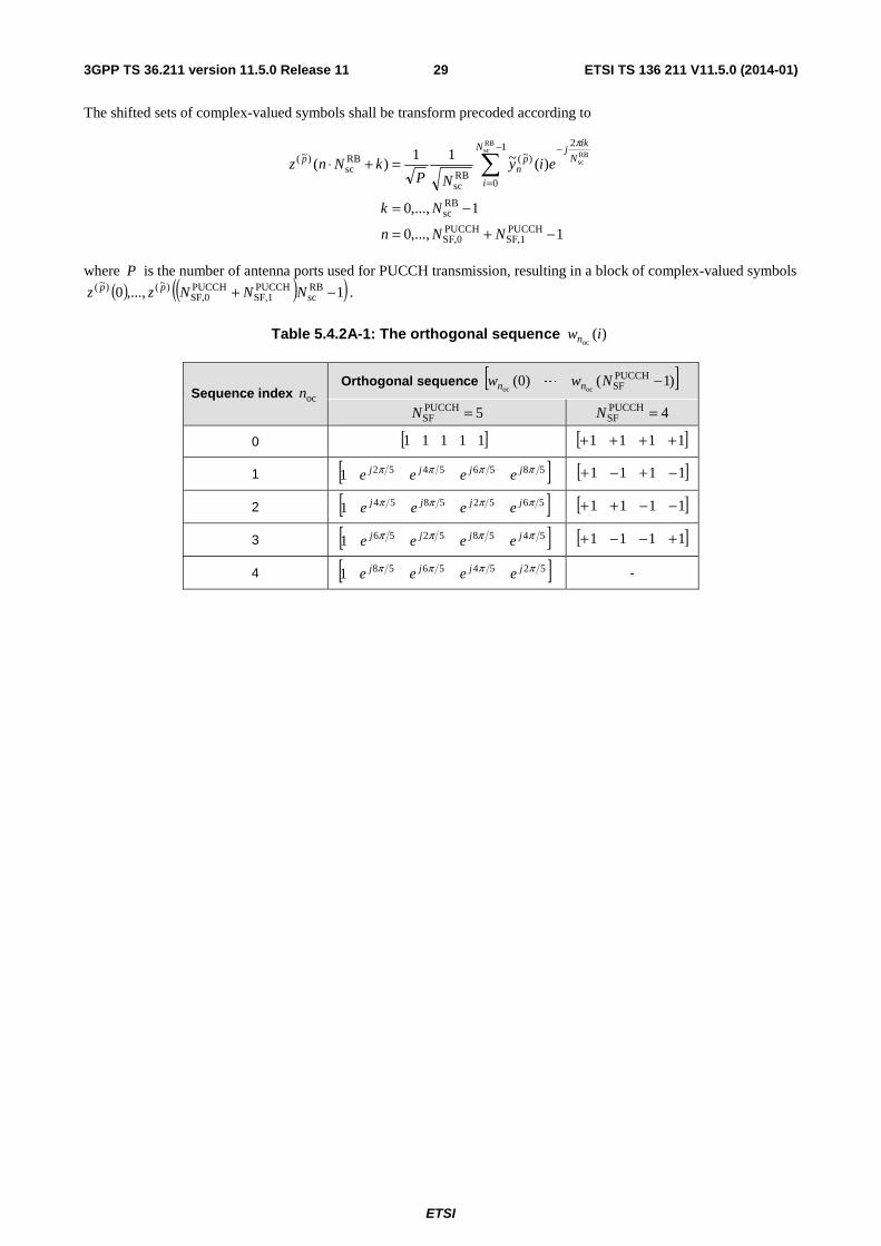
ETSI
ETSI TS 136 211 V11.5.0 (2014-01)293GPP TS 36.211 version 11.5.0 Release 11
The shifted sets of complex-valued symbols shall be transform precoded according to
1,...,0
1,...,0
)(~11)(
PUCCHSF,1
PUCCHSF,0
RBsc
1
0
2
)~(
RBsc
RBsc
)~(
RBsc
RBsc
−+=
−=
=+⋅ ∑−
=
−
NNn
Nk
eiyNP
kNnzN
i
N
ikj
pn
p
π
where P is the number of antenna ports used for PUCCH transmission, resulting in a block of complex-valued symbols
( ) ( )( )1,...,0 RBsc
PUCCHSF,1
PUCCHSF,0
)~()~( −+ NNNzz pp .
Table 5.4.2A-1: The orthogonal sequence )(oc
iwn
Sequence index ocn Orthogonal sequence [ ])1()0( PUCCH
SFococ−Nww nn L
5PUCCHSF =N 4PUCCH
SF =N
0 [ ]11111 [ ]1111 ++++
1 [ ]585654521 ππππ jjjj eeee [ ]1111 −+−+
2 [ ]565258541 ππππ jjjj eeee [ ]1111 −−++
3 [ ]545852561 ππππ jjjj eeee [ ]1111 +−−+
4 [ ]525456581 ππππ jjjj eeee -
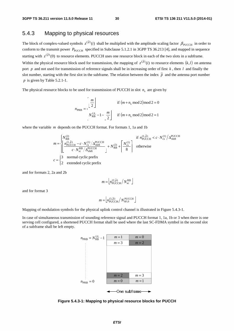
ETSI
ETSI TS 136 211 V11.5.0 (2014-01)303GPP TS 36.211 version 11.5.0 Release 11
5.4.3 Mapping to physical resources
The block of complex-valued symbols )()~( iz p shall be multiplied with the amplitude scaling factor PUCCHβ in order to
conform to the transmit power PUCCHP specified in Subclause 5.1.2.1 in 3GPP TS 36.213 [4], and mapped in sequence
starting with )0()~( pz to resource elements. PUCCH uses one resource block in each of the two slots in a subframe.
Within the physical resource block used for transmission, the mapping of )()~( iz p to resource elements ( )lk, on antenna
port p and not used for transmission of reference signals shall be in increasing order of first k , then l and finally the
slot number, starting with the first slot in the subframe. The relation between the index p~ and the antenna port number
p is given by Table 5.2.1-1.
The physical resource blocks to be used for transmission of PUCCH in slot sn are given by
( )
( )⎪⎪
⎩
⎪⎪
⎨
⎧
=+⎥⎦
⎥⎢⎣
⎢−−
=+⎥⎦
⎥⎢⎣
⎢
=12mod2mod if
21
02mod2mod if2
sULRB
s
PRB
nmm
N
nmm
n
where the variable m depends on the PUCCH format. For formats 1, 1a and 1b
⎩⎨⎧
=
⎪⎩
⎪⎨
⎧
⎥⎥⎥
⎤
⎢⎢⎢
⎡++
⎥⎥⎦
⎥
⎢⎢⎣
⎢
Δ⋅Δ⋅−
Δ⋅<=
prefix cyclic extended2
prefix cyclic normal3
otherwise8
if(1)cs(2)
RBPUCCHshift
RBsc
PUCCHshift
(1)cs
)~(1,PUCCH
PUCCHshift
(1)cs
)~(1,PUCCH
(2)RB
c
NN
Nc
Ncn
NcnN
m p
p
and for formats 2, 2a and 2b
⎣ ⎦RBsc
)~(2,PUCCH Nnm p=
and for format 3
⎣ ⎦PUCCHSF,0
)~(3,PUCCH Nnm p=
Mapping of modulation symbols for the physical uplink control channel is illustrated in Figure 5.4.3-1.
In case of simultaneous transmission of sounding reference signal and PUCCH format 1, 1a, 1b or 3 when there is one serving cell configured, a shortened PUCCH format shall be used where the last SC-FDMA symbol in the second slot of a subframe shall be left empty.
0=m
0=m1=m
1=m
2=m
2=m3=m
3=m
0PRB =n
1ULRBPRB −= Nn
Figure 5.4.3-1: Mapping to physical resource blocks for PUCCH
ETSI
ETSI TS 136 211 V11.5.0 (2014-01)313GPP TS 36.211 version 11.5.0 Release 11
5.5 Reference signals Two types of uplink reference signals are supported:
- Demodulation reference signal, associated with transmission of PUSCH or PUCCH
- Sounding reference signal, not associated with transmission of PUSCH or PUCCH
The same set of base sequences is used for demodulation and sounding reference signals.
5.5.1 Generation of the reference signal sequence
Reference signal sequence )()(, nr vuα is defined by a cyclic shift α of a base sequence )(, nr vu according to
RSsc,
)(, 0),()( Mnnrenr vu
njvu <≤= αα
where RBsc
RSsc mNM = is the length of the reference signal sequence and ULmax,
RB1 Nm ≤≤ . Multiple reference signal
sequences are defined from a single base sequence through different values of α .
Base sequences )(, nr vu are divided into groups, where { }29,...,1,0∈u is the group number and v is the base sequence
number within the group, such that each group contains one base sequence ( 0=v ) of each length RBsc
RSsc mNM = ,
51 ≤≤ m and two base sequences ( 1,0=v ) of each length RBsc
RSsc mNM = , ULmax,
RB6 Nm ≤≤ . The sequence group
number u and the number v within the group may vary in time as described in clauses 5.5.1.3 and 5.5.1.4,
respectively. The definition of the base sequence )1(),...,0( RSsc,, −Mrr vuvu depends on the sequence length RS
scM .
5.5.1.1 Base sequences of length RBsc3N or larger
For RBsc
RSsc 3NM ≥ , the base sequence )1(),...,0( RS
sc,, −Mrr vuvu is given by
RSsc
RSZC, 0),mod()( MnNnxnr qvu <≤=
where the thq root Zadoff-Chu sequence is defined by
( ) 10, RSZC
)1(RSZC −≤≤=
+−Nmemx N
mqmj
q
π
with q given by
⎣ ⎦ ⎣ ⎦
31)1(
)1(21RSZC
2
+⋅=
−⋅++=
uNq
vqq q
The length RSZCN of the Zadoff-Chu sequence is given by the largest prime number such that RS
scRSZC MN < .
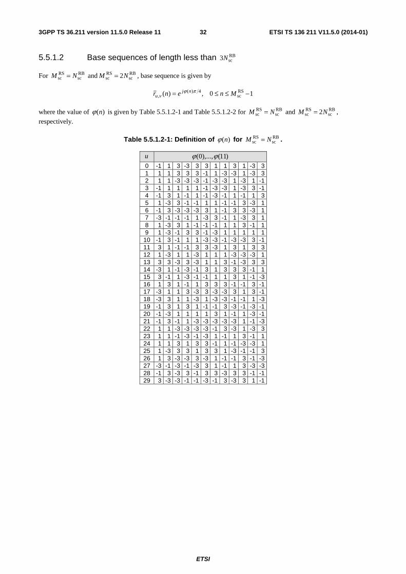
ETSI
ETSI TS 136 211 V11.5.0 (2014-01)323GPP TS 36.211 version 11.5.0 Release 11
5.5.1.2 Base sequences of length less than RBsc3N
For RBsc
RSsc NM = and RB
scRSsc 2NM = , base sequence is given by
10,)( RSsc
4)(, −≤≤= Mnenr njvu
πϕ
where the value of )(nϕ is given by Table 5.5.1.2-1 and Table 5.5.1.2-2 for RBsc
RSsc NM = and RB
scRSsc 2NM = ,
respectively.
Table 5.5.1.2-1: Definition of )(nϕ for RBsc
RSsc NM = .
u )11(),...,0( ϕϕ
0 -1 1 3 -3 3 3 1 1 3 1 -3 3 1 1 1 3 3 3 -1 1 -3 -3 1 -3 3 2 1 1 -3 -3 -3 -1 -3 -3 1 -3 1 -1 3 -1 1 1 1 1 -1 -3 -3 1 -3 3 -1 4 -1 3 1 -1 1 -1 -3 -1 1 -1 1 3 5 1 -3 3 -1 -1 1 1 -1 -1 3 -3 1 6 -1 3 -3 -3 -3 3 1 -1 3 3 -3 1 7 -3 -1 -1 -1 1 -3 3 -1 1 -3 3 1 8 1 -3 3 1 -1 -1 -1 1 1 3 -1 1 9 1 -3 -1 3 3 -1 -3 1 1 1 1 1
10 -1 3 -1 1 1 -3 -3 -1 -3 -3 3 -1 11 3 1 -1 -1 3 3 -3 1 3 1 3 3 12 1 -3 1 1 -3 1 1 1 -3 -3 -3 1 13 3 3 -3 3 -3 1 1 3 -1 -3 3 3 14 -3 1 -1 -3 -1 3 1 3 3 3 -1 1 15 3 -1 1 -3 -1 -1 1 1 3 1 -1 -3 16 1 3 1 -1 1 3 3 3 -1 -1 3 -1 17 -3 1 1 3 -3 3 -3 -3 3 1 3 -1 18 -3 3 1 1 -3 1 -3 -3 -1 -1 1 -3 19 -1 3 1 3 1 -1 -1 3 -3 -1 -3 -1 20 -1 -3 1 1 1 1 3 1 -1 1 -3 -1 21 -1 3 -1 1 -3 -3 -3 -3 -3 1 -1 -3 22 1 1 -3 -3 -3 -3 -1 3 -3 1 -3 3 23 1 1 -1 -3 -1 -3 1 -1 1 3 -1 1 24 1 1 3 1 3 3 -1 1 -1 -3 -3 1 25 1 -3 3 3 1 3 3 1 -3 -1 -1 3 26 1 3 -3 -3 3 -3 1 -1 -1 3 -1 -3 27 -3 -1 -3 -1 -3 3 1 -1 1 3 -3 -3 28 -1 3 -3 3 -1 3 3 -3 3 3 -1 -1 29 3 -3 -3 -1 -1 -3 -1 3 -3 3 1 -1
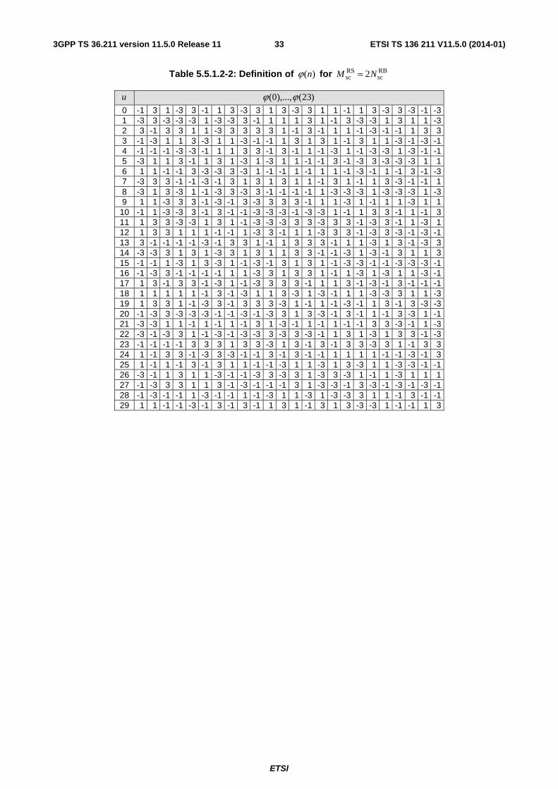
ETSI
ETSI TS 136 211 V11.5.0 (2014-01)333GPP TS 36.211 version 11.5.0 Release 11
Table 5.5.1.2-2: Definition of )(nϕ for RBsc
RSsc 2NM =
u )23(),...,0( ϕϕ
0 -1 3 1 -3 3 -1 1 3 -3 3 1 3 -3 3 1 1 -1 1 3 -3 3 -3 -1 -3 1 -3 3 -3 -3 -3 1 -3 -3 3 -1 1 1 1 3 1 -1 3 -3 -3 1 3 1 1 -3 2 3 -1 3 3 1 1 -3 3 3 3 3 1 -1 3 -1 1 1 -1 -3 -1 -1 1 3 3 3 -1 -3 1 1 3 -3 1 1 -3 -1 -1 1 3 1 3 1 -1 3 1 1 -3 -1 -3 -1 4 -1 -1 -1 -3 -3 -1 1 1 3 3 -1 3 -1 1 -1 -3 1 -1 -3 -3 1 -3 -1 -1 5 -3 1 1 3 -1 1 3 1 -3 1 -3 1 1 -1 -1 3 -1 -3 3 -3 -3 -3 1 1 6 1 1 -1 -1 3 -3 -3 3 -3 1 -1 -1 1 -1 1 1 -1 -3 -1 1 -1 3 -1 -3 7 -3 3 3 -1 -1 -3 -1 3 1 3 1 3 1 1 -1 3 1 -1 1 3 -3 -1 -1 1 8 -3 1 3 -3 1 -1 -3 3 -3 3 -1 -1 -1 -1 1 -3 -3 -3 1 -3 -3 -3 1 -3 9 1 1 -3 3 3 -1 -3 -1 3 -3 3 3 3 -1 1 1 -3 1 -1 1 1 -3 1 1
10 -1 1 -3 -3 3 -1 3 -1 -1 -3 -3 -3 -1 -3 -3 1 -1 1 3 3 -1 1 -1 3 11 1 3 3 -3 -3 1 3 1 -1 -3 -3 -3 3 3 -3 3 3 -1 -3 3 -1 1 -3 1 12 1 3 3 1 1 1 -1 -1 1 -3 3 -1 1 1 -3 3 3 -1 -3 3 -3 -1 -3 -1 13 3 -1 -1 -1 -1 -3 -1 3 3 1 -1 1 3 3 3 -1 1 1 -3 1 3 -1 -3 3 14 -3 -3 3 1 3 1 -3 3 1 3 1 1 3 3 -1 -1 -3 1 -3 -1 3 1 1 3 15 -1 -1 1 -3 1 3 -3 1 -1 -3 -1 3 1 3 1 -1 -3 -3 -1 -1 -3 -3 -3 -1 16 -1 -3 3 -1 -1 -1 -1 1 1 -3 3 1 3 3 1 -1 1 -3 1 -3 1 1 -3 -1 17 1 3 -1 3 3 -1 -3 1 -1 -3 3 3 3 -1 1 1 3 -1 -3 -1 3 -1 -1 -1 18 1 1 1 1 1 -1 3 -1 -3 1 1 3 -3 1 -3 -1 1 1 -3 -3 3 1 1 -3 19 1 3 3 1 -1 -3 3 -1 3 3 3 -3 1 -1 1 -1 -3 -1 1 3 -1 3 -3 -3 20 -1 -3 3 -3 -3 -3 -1 -1 -3 -1 -3 3 1 3 -3 -1 3 -1 1 -1 3 -3 1 -1 21 -3 -3 1 1 -1 1 -1 1 -1 3 1 -3 -1 1 -1 1 -1 -1 3 3 -3 -1 1 -3 22 -3 -1 -3 3 1 -1 -3 -1 -3 -3 3 -3 3 -3 -1 1 3 1 -3 1 3 3 -1 -3 23 -1 -1 -1 -1 3 3 3 1 3 3 -3 1 3 -1 3 -1 3 3 -3 3 1 -1 3 3 24 1 -1 3 3 -1 -3 3 -3 -1 -1 3 -1 3 -1 -1 1 1 1 1 -1 -1 -3 -1 3 25 1 -1 1 -1 3 -1 3 1 1 -1 -1 -3 1 1 -3 1 3 -3 1 1 -3 -3 -1 -1 26 -3 -1 1 3 1 1 -3 -1 -1 -3 3 -3 3 1 -3 3 -3 1 -1 1 -3 1 1 1 27 -1 -3 3 3 1 1 3 -1 -3 -1 -1 -1 3 1 -3 -3 -1 3 -3 -1 -3 -1 -3 -1 28 -1 -3 -1 -1 1 -3 -1 -1 1 -1 -3 1 1 -3 1 -3 -3 3 1 1 -1 3 -1 -1 29 1 1 -1 -1 -3 -1 3 -1 3 -1 1 3 1 -1 3 1 3 -3 -3 1 -1 -1 1 3
ETSI
ETSI TS 136 211 V11.5.0 (2014-01)343GPP TS 36.211 version 11.5.0 Release 11
5.5.1.3 Group hopping
The sequence-group number u in slot sn is defined by a group hopping pattern )( sgh nf and a sequence-shift pattern
ssf according to
( ) 30mod)( sssgh fnfu +=
There are 17 different hopping patterns and 30 different sequence-shift patterns. Sequence-group hopping can be enabled or disabled by means of the cell-specific parameter Group-hopping-enabled provided by higher layers. Sequence-group hopping for PUSCH can be disabled for a certain UE through the higher-layer parameter Disable-sequence-group-hopping despite being enabled on a cell basis unless the PUSCH transmission corresponds to a Random Access Response Grant or a retransmission of the same transport block as part of the contention based random access procedure.
The group-hopping pattern )( sgh nf may be different for PUSCH, PUCCH and SRS and is given by
⎪⎩
⎪⎨⎧
⎟⎠⎞
⎜⎝⎛ ⋅+=∑ = enabled is hopping group if30mod2)8(
disabled is hopping group if0)( 7
0 ssgh
iiinc
nf
where the pseudo-random sequence )(ic is defined by clause 7.2. The pseudo-random sequence generator shall be
initialized with ⎥⎥⎦
⎥
⎢⎢⎣
⎢=
30
RSID
initn
c at the beginning of each radio frame where RSIDn is given by clause 5.5.1.5.
The sequence-shift pattern ssf definition differs between PUCCH, PUSCH and SRS.
For PUCCH, the sequence-shift pattern PUCCHssf is given by 30modRS
IDPUCCH
ss nf = where RSIDn is given by clause
5.5.1.5.
For PUSCH, the sequence-shift pattern PUSCHssf is given by ( ) 30modss
cellID
PUSCHss Δ+= Nf , where { }29,...,1,0ss ∈Δ is
configured by higher layers, if no value for PUSCHIDn is provided by higher layers or if the PUSCH transmission
corresponds to a Random Access Response Grant or a retransmission of the same transport block as part of the
contention based random access procedure, otherwise it is given by 30modRSID
PUSCHss nf = with RS
IDn given by clause
5.5.1.5.
For SRS, the sequence-shift pattern SRSssf is given by 30modRS
IDSRS
ss nf = where RSIDn is given by clause 5.5.1.5.
ETSI
ETSI TS 136 211 V11.5.0 (2014-01)353GPP TS 36.211 version 11.5.0 Release 11
5.5.1.4 Sequence hopping
Sequence hopping only applies for reference-signals of length RBsc
RSsc 6NM ≥ .
For reference-signals of length RBsc
RSsc 6NM < , the base sequence number v within the base sequence group is given by
0=v .
For reference-signals of length RBsc
RSsc 6NM ≥ , the base sequence number v within the base sequence group in slot sn
is defined by
⎩⎨⎧
=otherwise0
enabled is hopping sequence and disabled is hopping group if)( sncv
where the pseudo-random sequence )(ic is given by clause 7.2. The parameter Sequence-hopping-enabled provided by
higher layers determines if sequence hopping is enabled or not. Sequence hopping for PUSCH can be disabled for a certain UE through the higher-layer parameter Disable-sequence-group-hopping despite being enabled on a cell basis unless the PUSCH transmission corresponds to a Random Access Response Grant or a retransmission of the same transport block as part of the contention based random access procedure.
For PUSCH, the pseudo-random sequence generator shall be initialized with PUSCHss
5RSID
init 230
fn
c +⋅⎥⎥⎦
⎥
⎢⎢⎣
⎢= at the
beginning of each radio frame where RSIDn is given by clause 5.5.1.5.
For SRS, the pseudo-random sequence generator shall be initialized with ( ) 30mod230 ss
RSID
5RSID
init Δ++⋅⎥⎥⎦
⎥
⎢⎢⎣
⎢= n
nc at the
beginning of each radio frame where RSIDn is given by clause 5.5.1.5 and ssΔ is given by clause 5.5.1.3.
5.5.1.5 Determining virtual cell identity for sequence generation
The definition of RSIDn depends on the type of transmission.
Transmissions associated with PUSCH:
- cellID
RSID Nn = if no value for PUSCH
IDn is configured by higher layers or if the PUSCH transmission corresponds to
a Random Access Response Grant or a retransmission of the same transport block as part of the contention based random access procedure,
- PUSCHID
RSID nn = otherwise.
Transmissions associated with PUCCH:
- cellID
RSID Nn = if no value for PUCCH
IDn is configured by higher layers,
- PUCCHID
RSID nn = otherwise.
Sounding reference signals:
- cellID
RSID Nn = .
ETSI
ETSI TS 136 211 V11.5.0 (2014-01)363GPP TS 36.211 version 11.5.0 Release 11
5.5.2 Demodulation reference signal
5.5.2.1 Demodulation reference signal for PUSCH
5.5.2.1.1 Reference signal sequence
The PUSCH demodulation reference signal sequence ( )⋅)(PUSCH
λr associated with layer { }1,...,1,0 −∈ υλ is defined by
( ) ( )nrmwnMmr vu)(
,)(RS
sc)(
PUSCH )( λαλλ =+⋅
where
1,...,0
1,0RSsc −=
=
Mn
m
and
PUSCHsc
RSsc MM =
Subclause 5.5.1 defines the sequence )1(),...,0( RSsc
)(,
)(, −Mrr vuvu
λλ αα . The orthogonal sequence )()( mw λ is given by
[ ] [ ]11)1()0( =λλ ww for DCI format 0 if the higher-layer parameter Activate-DMRS-with OCC is not set or if the
temporary C-RNTI was used to transmit the most recent uplink-related DCI for the transport block associated with the corresponding PUSCH transmission, otherwise it is given by Table 5.5.2.1.1-1 using the cyclic shift field in most recent uplink-related DCI 3GPP TS 36.212 [3] for the transport block associated with the corresponding PUSCH transmission.
The cyclic shift λα in a slot sn is given as 122 cs,λλ πα n= with
( ) 12mod)( sPN)2(
DMRS,)1(
DMRScs, nnnnn ++= λλ
where the values of (1)DMRSn is given by Table 5.5.2.1.1-2 according to the parameter cyclicShift provided by higher
layers, (2)DMRS,λn is given by the cyclic shift for DMRS field in most recent uplink-related DCI 3GPP TS 36.212 [3] for
the transport block associated with the corresponding PUSCH transmission where the value of (2)DMRS,λn is given in
Table 5.5.2.1.1-1.
The first row of Table 5.5.2.1.1-1 shall be used to obtain (2)0DMRS,n and )()( mw λ if there is no uplink-related DCI for the
same transport block associated with the corresponding PUSCH transmission, and
- if the initial PUSCH for the same transport block is semi-persistently scheduled, or
- if the initial PUSCH for the same transport block is scheduled by the random access response grant.
The quantity )( sPN nn is given by
∑ =⋅+⋅=
7
0 sULsymbsPN 2)8()(
i
iinNcnn
where the pseudo-random sequence )(ic is defined by clause 7.2. The application of )(ic is cell-specific. The pseudo-
random sequence generator shall be initialized with initc at the beginning of each radio frame. The quantity initc is
given by ( )( )30mod230 ss
cellID
5cellID
init Δ++⋅⎥⎥⎦
⎥
⎢⎢⎣
⎢= N
Nc if no value for csh_DMRS
IDN is configured by higher layers or the
PUSCH transmission corresponds to a Random Access Response Grant or a retransmission of the same transport block
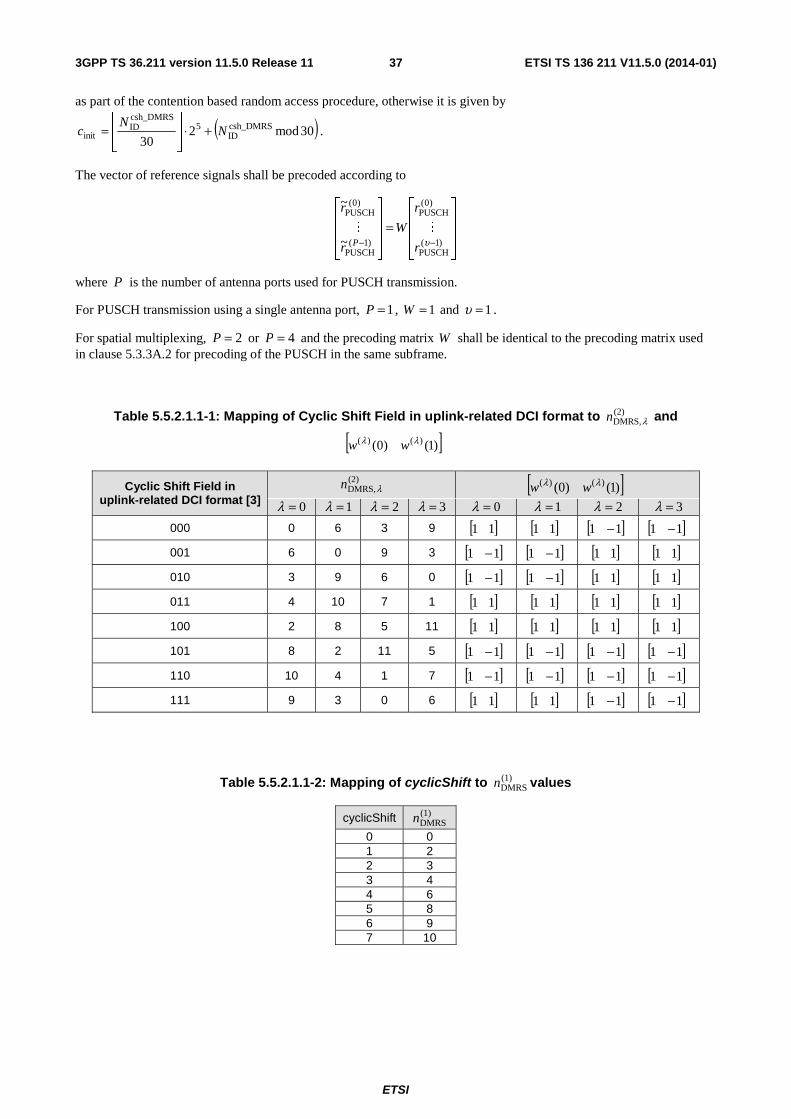
ETSI
ETSI TS 136 211 V11.5.0 (2014-01)373GPP TS 36.211 version 11.5.0 Release 11
as part of the contention based random access procedure, otherwise it is given by
( )30mod230
csh_DMRSID
5csh_DMRSID
init NN
c +⋅⎥⎥⎦
⎥
⎢⎢⎣
⎢= .
The vector of reference signals shall be precoded according to
⎥⎥⎥
⎦
⎤
⎢⎢⎢
⎣
⎡
=⎥⎥⎥
⎦
⎤
⎢⎢⎢
⎣
⎡
−− )1(PUSCH
)0(PUSCH
)1(PUSCH
)0(PUSCH
~
~
υr
r
W
r
r
P
MM
where P is the number of antenna ports used for PUSCH transmission.
For PUSCH transmission using a single antenna port, 1=P , 1=W and 1=υ .
For spatial multiplexing, 2=P or 4=P and the precoding matrix W shall be identical to the precoding matrix used in clause 5.3.3A.2 for precoding of the PUSCH in the same subframe.
Table 5.5.2.1.1-1: Mapping of Cyclic Shift Field in uplink-related DCI format to (2)DMRS,λn and
[ ])1()0( )()( λλ ww
Cyclic Shift Field in uplink-related DCI format [3]
(2)DMRS,λn [ ])1()0( )()( λλ ww
0=λ 1=λ 2=λ 3=λ 0=λ 1=λ 2=λ 3=λ
000 0 6 3 9 [ ]11 [ ]11 [ ]11 − [ ]11 −
001 6 0 9 3 [ ]11 − [ ]11 − [ ]11 [ ]11
010 3 9 6 0 [ ]11 − [ ]11 − [ ]11 [ ]11
011 4 10 7 1 [ ]11 [ ]11 [ ]11 [ ]11
100 2 8 5 11 [ ]11 [ ]11 [ ]11 [ ]11
101 8 2 11 5 [ ]11 − [ ]11 − [ ]11 − [ ]11 −
110 10 4 1 7 [ ]11 − [ ]11 − [ ]11 − [ ]11 −
111 9 3 0 6 [ ]11 [ ]11 [ ]11 − [ ]11 −
Table 5.5.2.1.1-2: Mapping of cyclicShift to (1)DMRSn values
cyclicShift (1)DMRSn
0 0 1 2 2 3 3 4 4 6 5 8 6 9 7 10
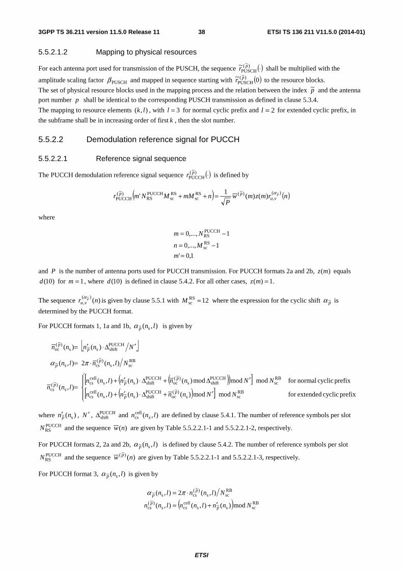
ETSI
ETSI TS 136 211 V11.5.0 (2014-01)383GPP TS 36.211 version 11.5.0 Release 11
5.5.2.1.2 Mapping to physical resources
For each antenna port used for transmission of the PUSCH, the sequence ( )⋅)~(PUSCH
~ pr shall be multiplied with the
amplitude scaling factor PUSCHβ and mapped in sequence starting with ( )0~ )~(PUSCH
pr to the resource blocks.
The set of physical resource blocks used in the mapping process and the relation between the index p~ and the antenna
port number p shall be identical to the corresponding PUSCH transmission as defined in clause 5.3.4.
The mapping to resource elements ),( lk , with 3=l for normal cyclic prefix and 2=l for extended cyclic prefix, in
the subframe shall be in increasing order of first k , then the slot number.
5.5.2.2 Demodulation reference signal for PUCCH
5.5.2.2.1 Reference signal sequence
The PUCCH demodulation reference signal sequence ( )⋅)~(PUCCH
pr is defined by
( ) ( )nrmzmwP
nmMMNmr pvu
pp )(,
)~(RSsc
RSsc
PUCCHRS
)~(PUCCH
~)()(
1'
α=++
where
1,0'
1,...,0
1,...,0RSsc
PUCCHRS
=−=
−=
m
Mn
Nm
and P is the number of antenna ports used for PUCCH transmission. For PUCCH formats 2a and 2b, )(mz equals
)10(d for 1=m , where )10(d is defined in clause 5.4.2. For all other cases, .1)( =mz
The sequence )()(
,~
nr pvu
αis given by clause 5.5.1 with 12RS
sc =M where the expression for the cyclic shift p~α is
determined by the PUCCH format.
For PUCCH formats 1, 1a and 1b, ),( s~ lnpα is given by
⎣ ⎦
( )( )[ ]( )[ ]⎪
⎩
⎪⎨
⎧
′+Δ⋅′+
′Δ+Δ⋅′+=
⋅=
′Δ⋅′=
prefix cyclic extendedfor modmod)()(),(
prefix cyclic normalfor modmodmod)()(),(),(
),(2),(
)()(
RBscs
)~(oc
PUCCHshifts~s
cellcs
RBsc
PUCCHshifts
)~(oc
PUCCHshifts~s
cellcs
s)~(
cs
RBscs
)~(css~
PUCCHshifts~s
)~(oc
NNnnnnlnn
NNnnnnlnnlnn
Nlnnln
Nnnnn
pp
ppp
pp
pp
πα
where )( s~ nnp′ , N ′ , PUCCHshiftΔ and ),(cell
cs lnn s are defined by clause 5.4.1. The number of reference symbols per slot
PUCCHRSN and the sequence )(nw are given by Table 5.5.2.2.1-1 and 5.5.2.2.1-2, respectively.
For PUCCH formats 2, 2a and 2b, ),( s~ lnpα is defined by clause 5.4.2. The number of reference symbols per slot
PUCCHRSN and the sequence )()~( nw p are given by Table 5.5.2.2.1-1 and 5.5.2.2.1-3, respectively.
For PUCCH format 3, ),( s~ lnpα is given by
( ) RBscs~s
cellcss
)~(cs
RBscs
)~(css~
mod)(),(),(
),(2),(
Nnnlnnlnn
Nlnnln
pp
pp
′+=
⋅= πα
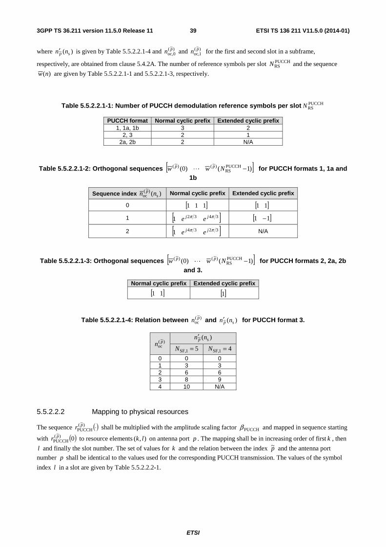
ETSI
ETSI TS 136 211 V11.5.0 (2014-01)393GPP TS 36.211 version 11.5.0 Release 11
where )( s~ nn p′ is given by Table 5.5.2.2.1-4 and )~(0oc,
pn and )~(1oc,
pn for the first and second slot in a subframe,
respectively, are obtained from clause 5.4.2A. The number of reference symbols per slot PUCCHRSN and the sequence
)(nw are given by Table 5.5.2.2.1-1 and 5.5.2.2.1-3, respectively.
Table 5.5.2.2.1-1: Number of PUCCH demodulation reference symbols per slot PUCCHRSN
PUCCH format Normal cyclic prefix Extended cyclic prefix 1, 1a, 1b 3 2
2, 3 2 1 2a, 2b 2 N/A
Table 5.5.2.2.1-2: Orthogonal sequences [ ])1()0( PUCCHRS
)~()~( −Nww ppL for PUCCH formats 1, 1a and
1b
Sequence index )( s)~(
oc nn p Normal cyclic prefix Extended cyclic prefix
0 [ ]111 [ ]11
1 [ ]34321 ππ jj ee [ ]11 −
2 [ ]32341 ππ jj ee N/A
Table 5.5.2.2.1-3: Orthogonal sequences [ ])1()0( PUCCHRS
)~()~( −Nww ppL for PUCCH formats 2, 2a, 2b
and 3.
Normal cyclic prefix Extended cyclic prefix
[ ]11 [ ]1
Table 5.5.2.2.1-4: Relation between )~(oc
pn and )( s~ nn p′ for PUCCH format 3.
)~(oc
pn )( s~ nn p′
51,SF =N
41,SF =N
0 0 0 1 3 3 2 6 6 3 8 9 4 10 N/A
5.5.2.2.2 Mapping to physical resources
The sequence ( )⋅)~(PUCCH
pr shall be multiplied with the amplitude scaling factor PUCCHβ and mapped in sequence starting
with ( )0)~(PUCCH
pr to resource elements ),( lk on antenna port p . The mapping shall be in increasing order of first k , then
l and finally the slot number. The set of values for k and the relation between the index p~ and the antenna port
number p shall be identical to the values used for the corresponding PUCCH transmission. The values of the symbol
index l in a slot are given by Table 5.5.2.2.2-1.
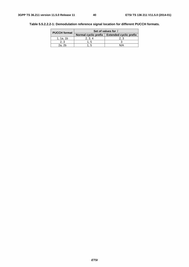
ETSI
ETSI TS 136 211 V11.5.0 (2014-01)403GPP TS 36.211 version 11.5.0 Release 11
Table 5.5.2.2.2-1: Demodulation reference signal location for different PUCCH formats.
PUCCH format Set of values for l Normal cyclic prefix Extended cyclic prefix
1, 1a, 1b 2, 3, 4 2, 3 2, 3 1, 5 3
2a, 2b 1, 5 N/A
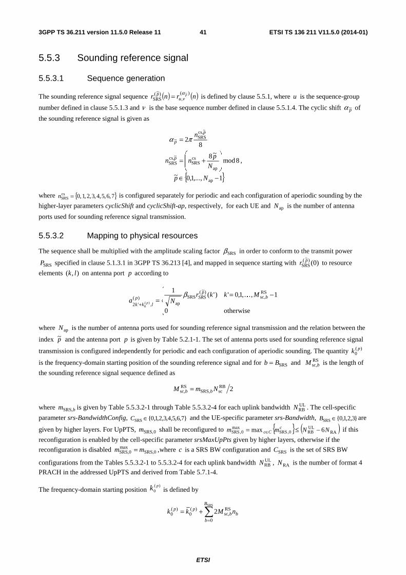
ETSI
ETSI TS 136 211 V11.5.0 (2014-01)413GPP TS 36.211 version 11.5.0 Release 11
5.5.3 Sounding reference signal
5.5.3.1 Sequence generation
The sounding reference signal sequence ( ) ( )nrnr pvu
p )(,
)~(SRS
~α= is defined by clause 5.5.1, where u is the sequence-group
number defined in clause 5.5.1.3 and ν is the base sequence number defined in clause 5.5.1.4. The cyclic shift p~α of
the sounding reference signal is given as
{ }1,...,1,0~
8mod~8
82
ap
ap
csSRS
~csSRS
~csSRS~
−∈
⎟⎟
⎠
⎞
⎜⎜
⎝
⎛+=
=
Np
N
pnn
n
p,
p,
p πα
,
where { }7,6,5,4,3,2,1,0csSRS =n is configured separately for periodic and each configuration of aperiodic sounding by the
higher-layer parameters cyclicShift and cyclicShift-ap, respectively, for each UE and apN is the number of antenna
ports used for sounding reference signal transmission.
5.5.3.2 Mapping to physical resources
The sequence shall be multiplied with the amplitude scaling factor SRSβ in order to conform to the transmit power
SRSP specified in clause 5.1.3.1 in 3GPP TS 36.213 [4], and mapped in sequence starting with )0()~(SRS
pr to resource
elements ),( lk on antenna port p according to
⎪⎩
⎪⎨
⎧ −==
+otherwise0
1,,1,0')'(1 RS
,sc)~(
SRSap
)(,'2 )(
0
bp
SRSplkk
MkkrNa p
Kβ
where apN is the number of antenna ports used for sounding reference signal transmission and the relation between the
index p~ and the antenna port p is given by Table 5.2.1-1. The set of antenna ports used for sounding reference signal
transmission is configured independently for periodic and each configuration of aperiodic sounding. The quantity )(0
pk
is the frequency-domain starting position of the sounding reference signal and for SRSBb = and RSsc,bM is the length of
the sounding reference signal sequence defined as
2RBscSRS,
RSsc, NmM bb =
where bmSRS, is given by Table 5.5.3.2-1 through Table 5.5.3.2-4 for each uplink bandwidth ULRBN . The cell-specific
parameter srs-BandwidthConfig, }7,6,5,4,3,2,1,0{SRS ∈C and the UE-specific parameter srs-Bandwidth, }3,2,1,0{SRS ∈B are
given by higher layers. For UpPTS, 0SRS,m shall be reconfigured to { } ( )RAULRB0,SRS
max0,SRS 6max NNmm c
Cc −≤= ∈ if this
reconfiguration is enabled by the cell-specific parameter srsMaxUpPts given by higher layers, otherwise if the
reconfiguration is disabled SRS,0maxSRS,0 mm = ,where c is a SRS BW configuration and SRSC is the set of SRS BW
configurations from the Tables 5.5.3.2-1 to 5.5.3.2-4 for each uplink bandwidth ULRBN , RAN is the number of format 4
PRACH in the addressed UpPTS and derived from Table 5.7.1-4.
The frequency-domain starting position )(
0pk is defined by
∑=
+=SRS
0
RSsc,
)(0
)(0 2
B
bbb
pp nMkk
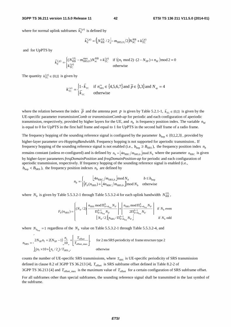
ETSI
ETSI TS 136 211 V11.5.0 (2014-01)423GPP TS 36.211 version 11.5.0 Release 11
where for normal uplink subframes )(0
pk is defined by
⎣ ⎦( ) )(TC
RBSC0SRS,
ULRB
)(0 22/ pp kNmNk +−=
and for UpPTS by
( )⎪⎩
⎪⎨⎧ =+−⋅+−
=otherwise
02mod)2()2mod( if)()(
TC
hfSPf)(
TCRBsc
maxSRS,0
ULRB)(
0 p
pp
k
nNnkNmNk
The quantity }1,0{)(TC ∈pk is given by
{ } { }⎩⎨⎧ =∈∈
=otherwise
4 and 3,1~ and 7,6,5,4 if-1
TC
apcsSRSTC)(
TCk
Npnkk p
where the relation between the index p~ and the antenna port p is given by Table 5.2.1-1, }1,0{TC ∈k is given by the
UE-specific parameter transmissionComb or transmissionComb-ap for periodic and each configuration of aperiodic transmission, respectively, provided by higher layers for the UE, and bn is frequency position index. The variable hfn
is equal to 0 for UpPTS in the first half frame and equal to 1 for UpPTS in the second half frame of a radio frame.
The frequency hopping of the sounding reference signal is configured by the parameter }3,2,1,0{hop ∈b , provided by
higher-layer parameter srs-HoppingBandwidth. Frequency hopping is not supported for aperiodic transmission.. If frequency hopping of the sounding reference signal is not enabled (i.e., SRShop Bb ≥ ), the frequency position index bn
remains constant (unless re-configured) and is defined by ⎣ ⎦ bSRS,RRCb mod4 Nmnn b= where the parameter RRCn is given
by higher-layer parameters freqDomainPosition and freqDomainPosition-ap for periodic and each configuration of aperiodic transmission, respectively. If frequency hopping of the sounding reference signal is enabled (i.e.,
SRShop Bb < ), the frequency position indexes bn are defined by
⎣ ⎦⎣ ⎦{ }⎩
⎨⎧
+≤
=otherwisemod4)(
mod4
SRS,RRCSRS
hopSRS,RRC
bbb
bbb NmnnF
bbNmnn
where bN is given by Table 5.5.3.2-1 through Table 5.5.3.2-4 for each uplink bandwidth ULRBN ,
⎣ ⎦⎣ ⎦⎪⎪⎩
⎪⎪⎨
⎧
Π
⎥⎥
⎦
⎥
⎢⎢
⎣
⎢
Π
Π+
⎥⎥
⎦
⎥
⎢⎢
⎣
⎢
Π
Π
=−=
−=
=−=
=
odd if/2/
even if2
modmod)2/(
)(
'1
'SRS
'1
'
''SRS
'1
'
''SRS
SRS
hop
hop
hop
hop
hop
bbb
bbb
bb
bbb
bb
bb
bb
bb
bb
bbb
b
NNnN
NN
Nn
N
NnN
nF
where 1hop
=bN regardless of the bN value on Table 5.5.3.2-1 through Table 5.5.3.2-4, and
( )
⎣ ⎦⎣ ⎦⎪⎪⎩
⎪⎪⎨
⎧
+×⎥⎥⎦
⎥
⎢⎢⎣
⎢+⎥
⎦
⎥⎢⎣
⎢−+=
otherwise ,/)2/10(
2 typestructure frame ofy periodicit SRS ms 2for ,10
122
SRSsf
offset_max
offsetsSPfSP
SRS
Tnn
T
TnNnN
n
counts the number of UE-specific SRS transmissions, where SRST is UE-specific periodicity of SRS transmission
defined in clause 8.2 of 3GPP TS 36.213 [4], offsetT is SRS subframe offset defined in Table 8.2-2 of
3GPP TS 36.213 [4] and offset_maxT is the maximum value of offsetT for a certain configuration of SRS subframe offset.
For all subframes other than special subframes, the sounding reference signal shall be transmitted in the last symbol of the subframe.
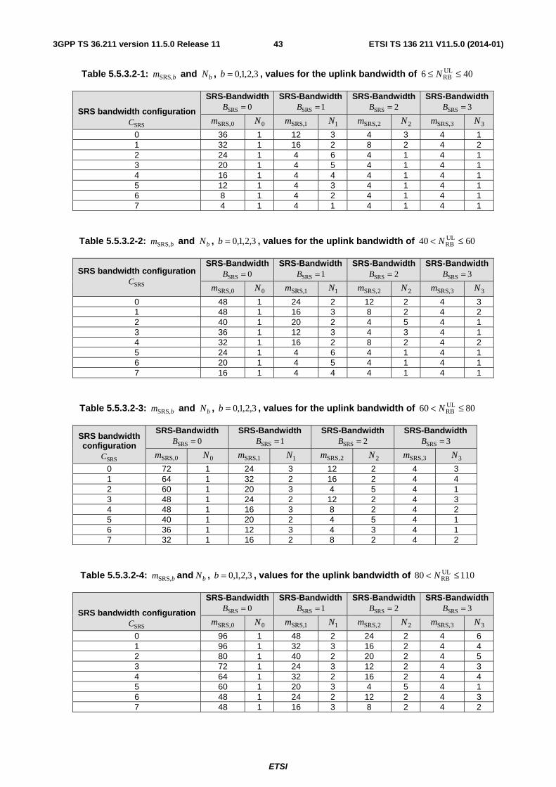
ETSI
ETSI TS 136 211 V11.5.0 (2014-01)433GPP TS 36.211 version 11.5.0 Release 11
Table 5.5.3.2-1: bmSRS, and bN , 3,2,1,0=b , values for the uplink bandwidth of 406 ULRB ≤≤ N
SRS bandwidth configuration
SRSC
SRS-Bandwidth 0SRS =B
SRS-Bandwidth 1SRS =B
SRS-Bandwidth 2SRS =B
SRS-Bandwidth 3SRS =B
0SRS,m 0N 1SRS,m
1N 2SRS,m 2N 3SRS,m
3N 0 36 1 12 3 4 3 4 1 1 32 1 16 2 8 2 4 2 2 24 1 4 6 4 1 4 1 3 20 1 4 5 4 1 4 1 4 16 1 4 4 4 1 4 1 5 12 1 4 3 4 1 4 1 6 8 1 4 2 4 1 4 1 7 4 1 4 1 4 1 4 1
Table 5.5.3.2-2: bmSRS, and bN , 3,2,1,0=b , values for the uplink bandwidth of 6040 ULRB ≤< N
SRS bandwidth configuration
SRSC
SRS-Bandwidth 0SRS =B
SRS-Bandwidth 1SRS =B
SRS-Bandwidth 2SRS =B
SRS-Bandwidth 3SRS =B
0SRS,m 0N 1SRS,m
1N 2SRS,m 2N 3SRS,m
3N 0 48 1 24 2 12 2 4 3 1 48 1 16 3 8 2 4 2 2 40 1 20 2 4 5 4 1 3 36 1 12 3 4 3 4 1 4 32 1 16 2 8 2 4 2 5 24 1 4 6 4 1 4 1 6 20 1 4 5 4 1 4 1 7 16 1 4 4 4 1 4 1
Table 5.5.3.2-3: bmSRS, and bN , 3,2,1,0=b , values for the uplink bandwidth of 8060 ULRB ≤< N
SRS bandwidth configuration
SRSC
SRS-Bandwidth 0SRS =B
SRS-Bandwidth 1SRS =B
SRS-Bandwidth 2SRS =B
SRS-Bandwidth 3SRS =B
0SRS,m 0N 1SRS,m
1N 2SRS,m 2N 3SRS,m
3N 0 72 1 24 3 12 2 4 3 1 64 1 32 2 16 2 4 4 2 60 1 20 3 4 5 4 1 3 48 1 24 2 12 2 4 3 4 48 1 16 3 8 2 4 2 5 40 1 20 2 4 5 4 1 6 36 1 12 3 4 3 4 1 7 32 1 16 2 8 2 4 2
Table 5.5.3.2-4: bmSRS, and bN , 3,2,1,0=b , values for the uplink bandwidth of 11080 ULRB ≤< N
SRS bandwidth configuration
SRSC
SRS-Bandwidth 0SRS =B
SRS-Bandwidth 1SRS =B
SRS-Bandwidth 2SRS =B
SRS-Bandwidth 3SRS =B
0SRS,m 0N 1SRS,m
1N 2SRS,m 2N 3SRS,m
3N 0 96 1 48 2 24 2 4 6 1 96 1 32 3 16 2 4 4 2 80 1 40 2 20 2 4 5 3 72 1 24 3 12 2 4 3 4 64 1 32 2 16 2 4 4 5 60 1 20 3 4 5 4 1 6 48 1 24 2 12 2 4 3 7 48 1 16 3 8 2 4 2
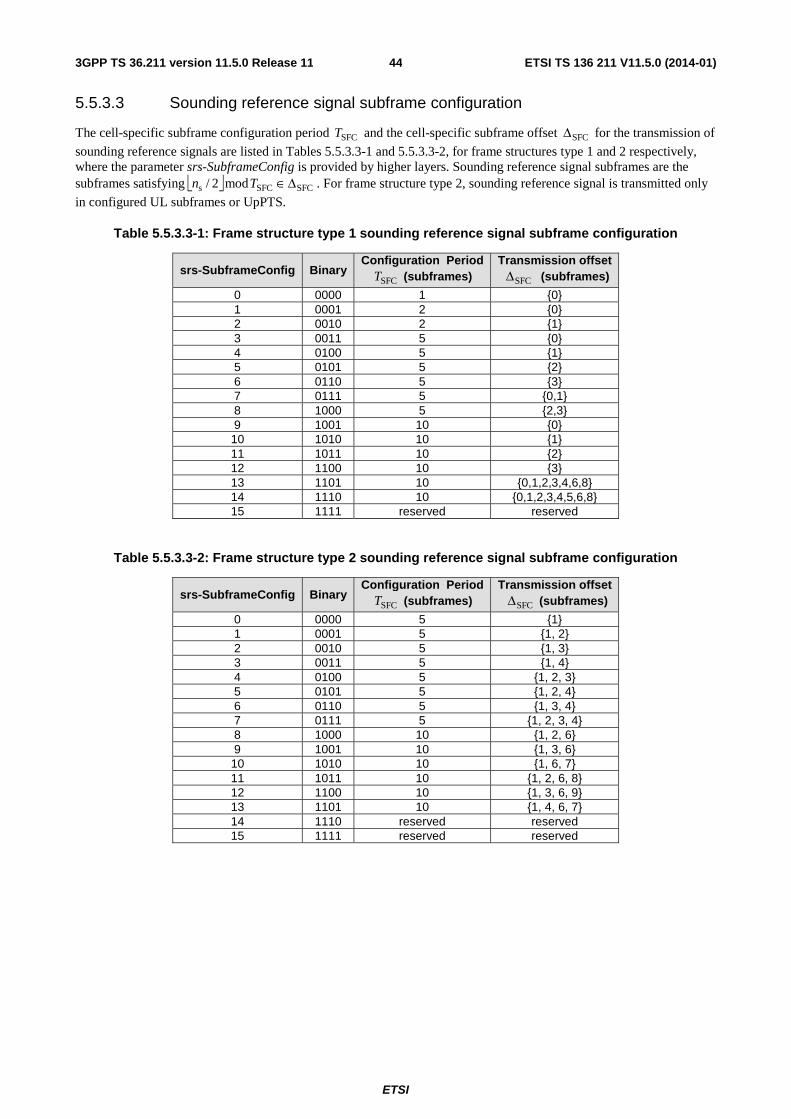
ETSI
ETSI TS 136 211 V11.5.0 (2014-01)443GPP TS 36.211 version 11.5.0 Release 11
5.5.3.3 Sounding reference signal subframe configuration
The cell-specific subframe configuration period SFCT and the cell-specific subframe offset SFCΔ for the transmission of
sounding reference signals are listed in Tables 5.5.3.3-1 and 5.5.3.3-2, for frame structures type 1 and 2 respectively, where the parameter srs-SubframeConfig is provided by higher layers. Sounding reference signal subframes are the subframes satisfying ⎣ ⎦ SFCSFCs mod2/ Δ∈Tn . For frame structure type 2, sounding reference signal is transmitted only
in configured UL subframes or UpPTS.
Table 5.5.3.3-1: Frame structure type 1 sounding reference signal subframe configuration
srs-SubframeConfig Binary Configuration Period
SFCT (subframes) Transmission offset SFCΔ (subframes)
0 0000 1 {0} 1 0001 2 {0} 2 0010 2 {1} 3 0011 5 {0} 4 0100 5 {1} 5 0101 5 {2} 6 0110 5 {3} 7 0111 5 {0,1} 8 1000 5 {2,3} 9 1001 10 {0} 10 1010 10 {1} 11 1011 10 {2} 12 1100 10 {3} 13 1101 10 {0,1,2,3,4,6,8} 14 1110 10 {0,1,2,3,4,5,6,8} 15 1111 reserved reserved
Table 5.5.3.3-2: Frame structure type 2 sounding reference signal subframe configuration
srs-SubframeConfig Binary Configuration Period
SFCT (subframes) Transmission offset SFCΔ (subframes)
0 0000 5 {1} 1 0001 5 {1, 2} 2 0010 5 {1, 3} 3 0011 5 {1, 4} 4 0100 5 {1, 2, 3} 5 0101 5 {1, 2, 4} 6 0110 5 {1, 3, 4} 7 0111 5 {1, 2, 3, 4} 8 1000 10 {1, 2, 6} 9 1001 10 {1, 3, 6} 10 1010 10 {1, 6, 7} 11 1011 10 {1, 2, 6, 8} 12 1100 10 {1, 3, 6, 9} 13 1101 10 {1, 4, 6, 7} 14 1110 reserved reserved 15 1111 reserved reserved
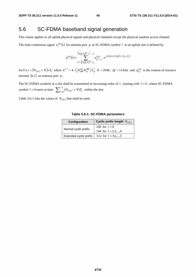
ETSI
ETSI TS 136 211 V11.5.0 (2014-01)453GPP TS 36.211 version 11.5.0 Release 11
5.6 SC-FDMA baseband signal generation This clause applies to all uplink physical signals and physical channels except the physical random access channel.
The time-continuous signal ( )ts pl
)( for antenna port p in SC-FDMA symbol l in an uplink slot is defined by
( ) ( ) ( )
⎣ ⎦
⎡ ⎤∑
−
−=
−Δ+⋅= −
12/
2/
212)(,
)(
RBsc
ULRB
RBsc
ULRB
s,CP)(
NN
NNk
TNtfkjplk
pl
leats π
for ( ) s,CP0 TNNt l ×+<≤ where ⎣ ⎦2)( RBsc
ULRB NNkk +=− , 2048=N , kHz 15=Δf and )(
,plka is the content of resource
element ( )lk, on antenna port p .
The SC-FDMA symbols in a slot shall be transmitted in increasing order of l , starting with 0=l , where SC-FDMA
symbol 0>l starts at time ∑−
=′ ′ +1
0 s,CP )(l
l l TNN within the slot.
Table 5.6-1 lists the values of lN ,CP that shall be used.
Table 5.6-1: SC-FDMA parameters
Configuration Cyclic prefix length lN ,CP
Normal cyclic prefix 0for 160 =l
6,...,2,1for 144 =l
Extended cyclic prefix 5,...,1,0for 512 =l
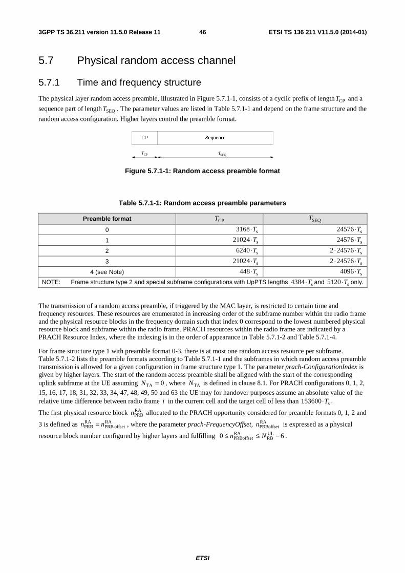
ETSI
ETSI TS 136 211 V11.5.0 (2014-01)463GPP TS 36.211 version 11.5.0 Release 11
5.7 Physical random access channel
5.7.1 Time and frequency structure
The physical layer random access preamble, illustrated in Figure 5.7.1-1, consists of a cyclic prefix of length CPT and a
sequence part of length SEQT . The parameter values are listed in Table 5.7.1-1 and depend on the frame structure and the
random access configuration. Higher layers control the preamble format.
SequenceCP
CPT SEQT
Figure 5.7.1-1: Random access preamble format
Table 5.7.1-1: Random access preamble parameters
Preamble format CPT SEQT
0 s3168 T⋅ s24576 T⋅
1 s21024 T⋅ s24576 T⋅
2 s6240 T⋅ s245762 T⋅⋅
3 s21024 T⋅ s245762 T⋅⋅
4 (see Note) s448 T⋅ s4096 T⋅
NOTE: Frame structure type 2 and special subframe configurations with UpPTS lengths s4384 T⋅ and s5120 T⋅ only.
The transmission of a random access preamble, if triggered by the MAC layer, is restricted to certain time and frequency resources. These resources are enumerated in increasing order of the subframe number within the radio frame and the physical resource blocks in the frequency domain such that index 0 correspond to the lowest numbered physical resource block and subframe within the radio frame. PRACH resources within the radio frame are indicated by a PRACH Resource Index, where the indexing is in the order of appearance in Table 5.7.1-2 and Table 5.7.1-4.
For frame structure type 1 with preamble format 0-3, there is at most one random access resource per subframe. Table 5.7.1-2 lists the preamble formats according to Table 5.7.1-1 and the subframes in which random access preamble transmission is allowed for a given configuration in frame structure type 1. The parameter prach-ConfigurationIndex is given by higher layers. The start of the random access preamble shall be aligned with the start of the corresponding uplink subframe at the UE assuming 0TA =N , where TAN is defined in clause 8.1. For PRACH configurations 0, 1, 2,
15, 16, 17, 18, 31, 32, 33, 34, 47, 48, 49, 50 and 63 the UE may for handover purposes assume an absolute value of the relative time difference between radio frame i in the current cell and the target cell of less than s153600 T⋅ .
The first physical resource block RAPRBn allocated to the PRACH opportunity considered for preamble formats 0, 1, 2 and
3 is defined as RAoffset PRB
RAPRB nn = , where the parameter prach-FrequencyOffset, RA
PRBoffsetn is expressed as a physical
resource block number configured by higher layers and fulfilling 60 ULRB
RAPRBoffset −≤≤ Nn .
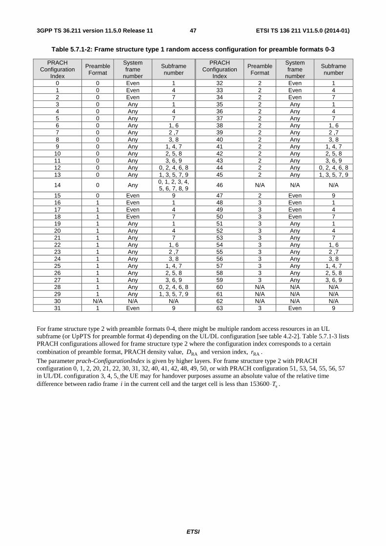
ETSI
ETSI TS 136 211 V11.5.0 (2014-01)473GPP TS 36.211 version 11.5.0 Release 11
Table 5.7.1-2: Frame structure type 1 random access configuration for preamble formats 0-3
PRACH Configuration
Index
Preamble Format
System frame
number
Subframe number
PRACH Configuration
Index
Preamble Format
System frame
number
Subframe number
0 0 Even 1 32 2 Even 1 1 0 Even 4 33 2 Even 4 2 0 Even 7 34 2 Even 7 3 0 Any 1 35 2 Any 1 4 0 Any 4 36 2 Any 4 5 0 Any 7 37 2 Any 7 6 0 Any 1, 6 38 2 Any 1, 6 7 0 Any 2 ,7 39 2 Any 2 ,7 8 0 Any 3, 8 40 2 Any 3, 8 9 0 Any 1, 4, 7 41 2 Any 1, 4, 7
10 0 Any 2, 5, 8 42 2 Any 2, 5, 8 11 0 Any 3, 6, 9 43 2 Any 3, 6, 9 12 0 Any 0, 2, 4, 6, 8 44 2 Any 0, 2, 4, 6, 8 13 0 Any 1, 3, 5, 7, 9 45 2 Any 1, 3, 5, 7, 9
14 0 Any 0, 1, 2, 3, 4, 5, 6, 7, 8, 9 46 N/A N/A N/A
15 0 Even 9 47 2 Even 9 16 1 Even 1 48 3 Even 1 17 1 Even 4 49 3 Even 4 18 1 Even 7 50 3 Even 7 19 1 Any 1 51 3 Any 1 20 1 Any 4 52 3 Any 4 21 1 Any 7 53 3 Any 7 22 1 Any 1, 6 54 3 Any 1, 6 23 1 Any 2 ,7 55 3 Any 2 ,7 24 1 Any 3, 8 56 3 Any 3, 8 25 1 Any 1, 4, 7 57 3 Any 1, 4, 7 26 1 Any 2, 5, 8 58 3 Any 2, 5, 8 27 1 Any 3, 6, 9 59 3 Any 3, 6, 9 28 1 Any 0, 2, 4, 6, 8 60 N/A N/A N/A 29 1 Any 1, 3, 5, 7, 9 61 N/A N/A N/A 30 N/A N/A N/A 62 N/A N/A N/A 31 1 Even 9 63 3 Even 9
For frame structure type 2 with preamble formats 0-4, there might be multiple random access resources in an UL subframe (or UpPTS for preamble format 4) depending on the UL/DL configuration [see table 4.2-2]. Table 5.7.1-3 lists PRACH configurations allowed for frame structure type 2 where the configuration index corresponds to a certain combination of preamble format, PRACH density value, RAD and version index, RAr .
The parameter prach-ConfigurationIndex is given by higher layers. For frame structure type 2 with PRACH configuration 0, 1, 2, 20, 21, 22, 30, 31, 32, 40, 41, 42, 48, 49, 50, or with PRACH configuration 51, 53, 54, 55, 56, 57 in UL/DL configuration 3, 4, 5, the UE may for handover purposes assume an absolute value of the relative time difference between radio frame i in the current cell and the target cell is less than s153600 T⋅ .
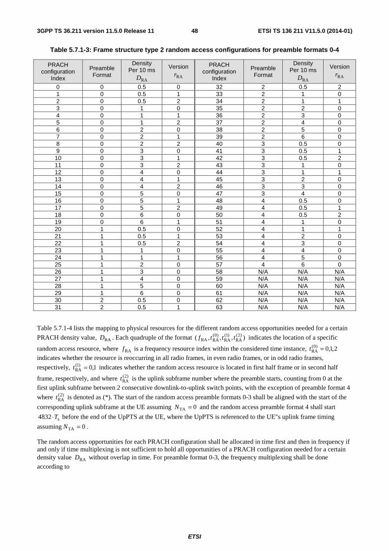
ETSI
ETSI TS 136 211 V11.5.0 (2014-01)483GPP TS 36.211 version 11.5.0 Release 11
Table 5.7.1-3: Frame structure type 2 random access configurations for preamble formats 0-4
PRACH configuration
Index
Preamble Format
Density Per 10 ms
RAD
Version
RAr
PRACH configuration
Index
Preamble Format
Density Per 10 ms
RAD
Version
RAr
0 0 0.5 0 32 2 0.5 2 1 0 0.5 1 33 2 1 0 2 0 0.5 2 34 2 1 1 3 0 1 0 35 2 2 0 4 0 1 1 36 2 3 0 5 0 1 2 37 2 4 0 6 0 2 0 38 2 5 0 7 0 2 1 39 2 6 0 8 0 2 2 40 3 0.5 0 9 0 3 0 41 3 0.5 1 10 0 3 1 42 3 0.5 2 11 0 3 2 43 3 1 0 12 0 4 0 44 3 1 1 13 0 4 1 45 3 2 0 14 0 4 2 46 3 3 0 15 0 5 0 47 3 4 0 16 0 5 1 48 4 0.5 0 17 0 5 2 49 4 0.5 1 18 0 6 0 50 4 0.5 2 19 0 6 1 51 4 1 0 20 1 0.5 0 52 4 1 1 21 1 0.5 1 53 4 2 0 22 1 0.5 2 54 4 3 0 23 1 1 0 55 4 4 0 24 1 1 1 56 4 5 0 25 1 2 0 57 4 6 0 26 1 3 0 58 N/A N/A N/A 27 1 4 0 59 N/A N/A N/A 28 1 5 0 60 N/A N/A N/A 29 1 6 0 61 N/A N/A N/A 30 2 0.5 0 62 N/A N/A N/A 31 2 0.5 1 63 N/A N/A N/A
Table 5.7.1-4 lists the mapping to physical resources for the different random access opportunities needed for a certain
PRACH density value, RAD . Each quadruple of the format ),,,( )2(RA
)1(RA
)0(RARA tttf indicates the location of a specific
random access resource, where RAf is a frequency resource index within the considered time instance, 2,1,0)0(RA =t
indicates whether the resource is reoccurring in all radio frames, in even radio frames, or in odd radio frames,
respectively, 1,0)1(RA =t indicates whether the random access resource is located in first half frame or in second half
frame, respectively, and where )2(RAt is the uplink subframe number where the preamble starts, counting from 0 at the
first uplink subframe between 2 consecutive downlink-to-uplink switch points, with the exception of preamble format 4
where )2(RAt is denoted as (*). The start of the random access preamble formats 0-3 shall be aligned with the start of the
corresponding uplink subframe at the UE assuming 0TA =N and the random access preamble format 4 shall start
s4832 T⋅ before the end of the UpPTS at the UE, where the UpPTS is referenced to the UE"s uplink frame timing
assuming 0TA =N .
The random access opportunities for each PRACH configuration shall be allocated in time first and then in frequency if and only if time multiplexing is not sufficient to hold all opportunities of a PRACH configuration needed for a certain density value RAD without overlap in time. For preamble format 0-3, the frequency multiplexing shall be done
according to
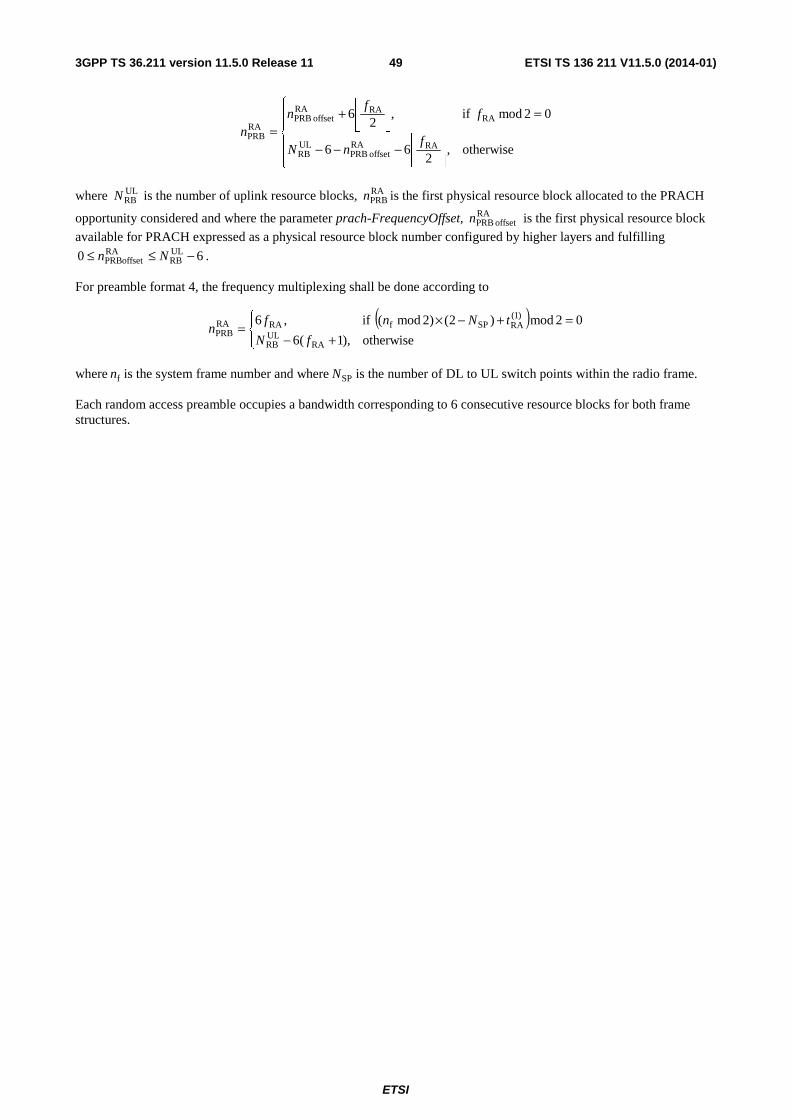
ETSI
ETSI TS 136 211 V11.5.0 (2014-01)493GPP TS 36.211 version 11.5.0 Release 11
⎪⎪⎩
⎪⎪⎨
⎧
⎥⎦
⎥⎢⎣
⎢−−−
=⎥⎦
⎥⎢⎣
⎢+=
otherwise,2
66
02mod if,2
6
RARAoffset PRB
ULRB
RARARA
offset PRBRAPRB f
nN
ff
nn
where ULRBN is the number of uplink resource blocks, RA
PRBn is the first physical resource block allocated to the PRACH
opportunity considered and where the parameter prach-FrequencyOffset, RAoffset PRBn is the first physical resource block
available for PRACH expressed as a physical resource block number configured by higher layers and fulfilling
60 ULRB
RAPRBoffset −≤≤ Nn .
For preamble format 4, the frequency multiplexing shall be done according to
( )⎪⎩
⎪⎨⎧
+−=+−×=
otherwise),1(6
02mod)2()2mod( if,6
RAULRB
)1(RASPfRARA
PRBfN
tNnfn
where fn is the system frame number and where SPN is the number of DL to UL switch points within the radio frame.
Each random access preamble occupies a bandwidth corresponding to 6 consecutive resource blocks for both frame structures.
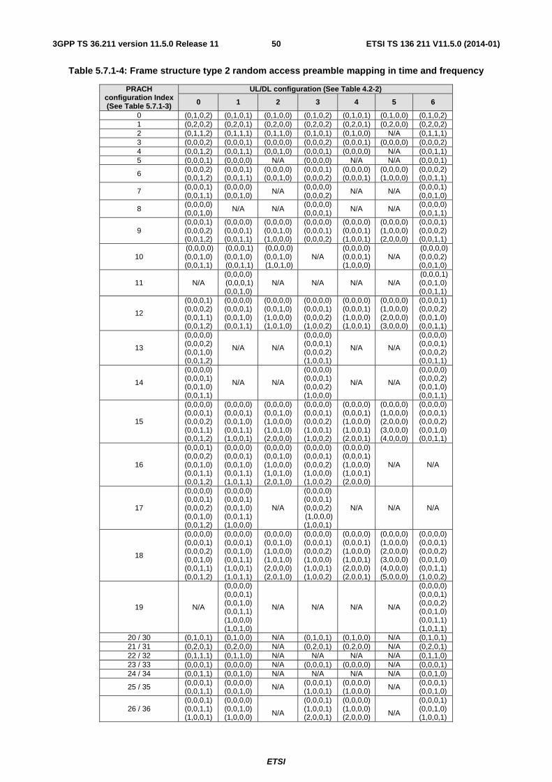
ETSI
ETSI TS 136 211 V11.5.0 (2014-01)503GPP TS 36.211 version 11.5.0 Release 11
Table 5.7.1-4: Frame structure type 2 random access preamble mapping in time and frequency
PRACH configuration Index (See Table 5.7.1-3)
UL/DL configuration (See Table 4.2-2)
0 1 2 3 4 5 6
0 (0,1,0,2) (0,1,0,1) (0,1,0,0) (0,1,0,2) (0,1,0,1) (0,1,0,0) (0,1,0,2) 1 (0,2,0,2) (0,2,0,1) (0,2,0,0) (0,2,0,2) (0,2,0,1) (0,2,0,0) (0,2,0,2) 2 (0,1,1,2) (0,1,1,1) (0,1,1,0) (0,1,0,1) (0,1,0,0) N/A (0,1,1,1) 3 (0,0,0,2) (0,0,0,1) (0,0,0,0) (0,0,0,2) (0,0,0,1) (0,0,0,0) (0,0,0,2) 4 (0,0,1,2) (0,0,1,1) (0,0,1,0) (0,0,0,1) (0,0,0,0) N/A (0,0,1,1) 5 (0,0,0,1) (0,0,0,0) N/A (0,0,0,0) N/A N/A (0,0,0,1)
6 (0,0,0,2) (0,0,1,2)
(0,0,0,1) (0,0,1,1)
(0,0,0,0) (0,0,1,0)
(0,0,0,1) (0,0,0,2)
(0,0,0,0) (0,0,0,1)
(0,0,0,0) (1,0,0,0)
(0,0,0,2) (0,0,1,1)
7 (0,0,0,1) (0,0,1,1)
(0,0,0,0) (0,0,1,0)
N/A (0,0,0,0) (0,0,0,2)
N/A N/A (0,0,0,1) (0,0,1,0)
8 (0,0,0,0) (0,0,1,0) N/A N/A
(0,0,0,0) (0,0,0,1) N/A N/A
(0,0,0,0) (0,0,1,1)
9 (0,0,0,1) (0,0,0,2) (0,0,1,2)
(0,0,0,0) (0,0,0,1) (0,0,1,1)
(0,0,0,0) (0,0,1,0) (1,0,0,0)
(0,0,0,0) (0,0,0,1) (0,0,0,2)
(0,0,0,0) (0,0,0,1) (1,0,0,1)
(0,0,0,0) (1,0,0,0) (2,0,0,0)
(0,0,0,1) (0,0,0,2) (0,0,1,1)
10 (0,0,0,0) (0,0,1,0) (0,0,1,1)
(0,0,0,1) (0,0,1,0) (0,0,1,1)
(0,0,0,0) (0,0,1,0) (1,0,1,0)
N/A (0,0,0,0) (0,0,0,1) (1,0,0,0)
N/A (0,0,0,0) (0,0,0,2) (0,0,1,0)
11 N/A (0,0,0,0) (0,0,0,1) (0,0,1,0)
N/A N/A N/A N/A (0,0,0,1) (0,0,1,0) (0,0,1,1)
12
(0,0,0,1) (0,0,0,2) (0,0,1,1) (0,0,1,2)
(0,0,0,0) (0,0,0,1) (0,0,1,0) (0,0,1,1)
(0,0,0,0) (0,0,1,0) (1,0,0,0) (1,0,1,0)
(0,0,0,0) (0,0,0,1) (0,0,0,2) (1,0,0,2)
(0,0,0,0) (0,0,0,1) (1,0,0,0) (1,0,0,1)
(0,0,0,0) (1,0,0,0) (2,0,0,0) (3,0,0,0)
(0,0,0,1) (0,0,0,2) (0,0,1,0) (0,0,1,1)
13
(0,0,0,0) (0,0,0,2) (0,0,1,0) (0,0,1,2)
N/A N/A
(0,0,0,0) (0,0,0,1) (0,0,0,2) (1,0,0,1)
N/A N/A
(0,0,0,0) (0,0,0,1) (0,0,0,2) (0,0,1,1)
14
(0,0,0,0) (0,0,0,1) (0,0,1,0) (0,0,1,1)
N/A N/A
(0,0,0,0) (0,0,0,1) (0,0,0,2) (1,0,0,0)
N/A N/A
(0,0,0,0) (0,0,0,2) (0,0,1,0) (0,0,1,1)
15
(0,0,0,0) (0,0,0,1) (0,0,0,2) (0,0,1,1) (0,0,1,2)
(0,0,0,0) (0,0,0,1) (0,0,1,0) (0,0,1,1) (1,0,0,1)
(0,0,0,0) (0,0,1,0) (1,0,0,0) (1,0,1,0) (2,0,0,0)
(0,0,0,0) (0,0,0,1) (0,0,0,2) (1,0,0,1) (1,0,0,2)
(0,0,0,0) (0,0,0,1) (1,0,0,0) (1,0,0,1) (2,0,0,1)
(0,0,0,0) (1,0,0,0) (2,0,0,0) (3,0,0,0) (4,0,0,0)
(0,0,0,0) (0,0,0,1) (0,0,0,2) (0,0,1,0) (0,0,1,1)
16
(0,0,0,1) (0,0,0,2) (0,0,1,0) (0,0,1,1) (0,0,1,2)
(0,0,0,0) (0,0,0,1) (0,0,1,0) (0,0,1,1) (1,0,1,1)
(0,0,0,0) (0,0,1,0) (1,0,0,0) (1,0,1,0) (2,0,1,0)
(0,0,0,0) (0,0,0,1) (0,0,0,2) (1,0,0,0) (1,0,0,2)
(0,0,0,0) (0,0,0,1) (1,0,0,0) (1,0,0,1) (2,0,0,0)
N/A N/A
17
(0,0,0,0) (0,0,0,1) (0,0,0,2) (0,0,1,0) (0,0,1,2)
(0,0,0,0) (0,0,0,1) (0,0,1,0) (0,0,1,1) (1,0,0,0)
N/A
(0,0,0,0) (0,0,0,1) (0,0,0,2) (1,0,0,0) (1,0,0,1)
N/A N/A N/A
18
(0,0,0,0) (0,0,0,1) (0,0,0,2) (0,0,1,0) (0,0,1,1) (0,0,1,2)
(0,0,0,0) (0,0,0,1) (0,0,1,0) (0,0,1,1) (1,0,0,1) (1,0,1,1)
(0,0,0,0) (0,0,1,0) (1,0,0,0) (1,0,1,0) (2,0,0,0) (2,0,1,0)
(0,0,0,0) (0,0,0,1) (0,0,0,2) (1,0,0,0) (1,0,0,1) (1,0,0,2)
(0,0,0,0) (0,0,0,1) (1,0,0,0) (1,0,0,1) (2,0,0,0) (2,0,0,1)
(0,0,0,0) (1,0,0,0) (2,0,0,0) (3,0,0,0) (4,0,0,0) (5,0,0,0)
(0,0,0,0) (0,0,0,1) (0,0,0,2) (0,0,1,0) (0,0,1,1) (1,0,0,2)
19 N/A
(0,0,0,0) (0,0,0,1) (0,0,1,0) (0,0,1,1) (1,0,0,0) (1,0,1,0)
N/A N/A N/A N/A
(0,0,0,0) (0,0,0,1) (0,0,0,2) (0,0,1,0) (0,0,1,1) (1,0,1,1)
20 / 30 (0,1,0,1) (0,1,0,0) N/A (0,1,0,1) (0,1,0,0) N/A (0,1,0,1) 21 / 31 (0,2,0,1) (0,2,0,0) N/A (0,2,0,1) (0,2,0,0) N/A (0,2,0,1) 22 / 32 (0,1,1,1) (0,1,1,0) N/A N/A N/A N/A (0,1,1,0) 23 / 33 (0,0,0,1) (0,0,0,0) N/A (0,0,0,1) (0,0,0,0) N/A (0,0,0,1) 24 / 34 (0,0,1,1) (0,0,1,0) N/A N/A N/A N/A (0,0,1,0)
25 / 35 (0,0,0,1) (0,0,1,1)
(0,0,0,0) (0,0,1,0) N/A (0,0,0,1)
(1,0,0,1) (0,0,0,0) (1,0,0,0) N/A (0,0,0,1)
(0,0,1,0)
26 / 36 (0,0,0,1) (0,0,1,1) (1,0,0,1)
(0,0,0,0) (0,0,1,0) (1,0,0,0)
N/A
(0,0,0,1) (1,0,0,1) (2,0,0,1)
(0,0,0,0) (1,0,0,0) (2,0,0,0)
N/A
(0,0,0,1) (0,0,1,0) (1,0,0,1)
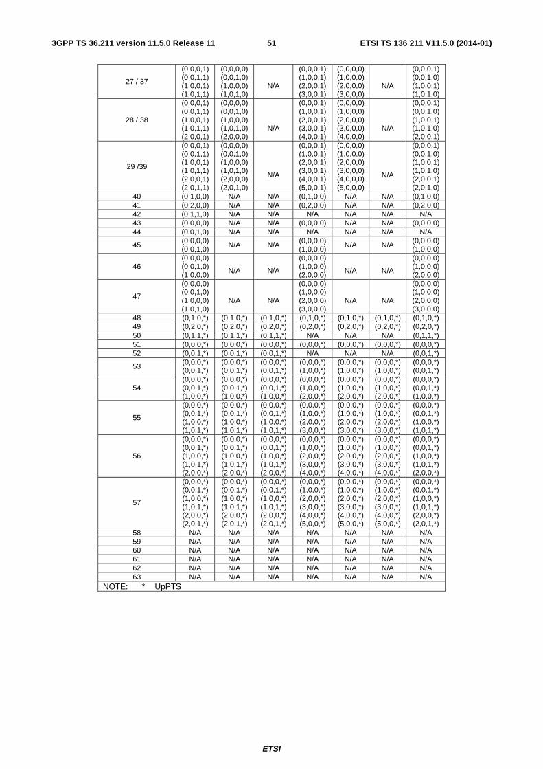
ETSI
ETSI TS 136 211 V11.5.0 (2014-01)513GPP TS 36.211 version 11.5.0 Release 11
27 / 37
(0,0,0,1) (0,0,1,1) (1,0,0,1) (1,0,1,1)
(0,0,0,0) (0,0,1,0) (1,0,0,0) (1,0,1,0)
N/A
(0,0,0,1) (1,0,0,1) (2,0,0,1) (3,0,0,1)
(0,0,0,0) (1,0,0,0) (2,0,0,0) (3,0,0,0)
N/A
(0,0,0,1) (0,0,1,0) (1,0,0,1) (1,0,1,0)
28 / 38
(0,0,0,1) (0,0,1,1) (1,0,0,1) (1,0,1,1) (2,0,0,1)
(0,0,0,0) (0,0,1,0) (1,0,0,0) (1,0,1,0) (2,0,0,0)
N/A
(0,0,0,1) (1,0,0,1) (2,0,0,1) (3,0,0,1) (4,0,0,1)
(0,0,0,0) (1,0,0,0) (2,0,0,0) (3,0,0,0) (4,0,0,0)
N/A
(0,0,0,1) (0,0,1,0) (1,0,0,1) (1,0,1,0) (2,0,0,1)
29 /39
(0,0,0,1) (0,0,1,1) (1,0,0,1) (1,0,1,1) (2,0,0,1) (2,0,1,1)
(0,0,0,0) (0,0,1,0) (1,0,0,0) (1,0,1,0) (2,0,0,0) (2,0,1,0)
N/A
(0,0,0,1) (1,0,0,1) (2,0,0,1) (3,0,0,1) (4,0,0,1) (5,0,0,1)
(0,0,0,0) (1,0,0,0) (2,0,0,0) (3,0,0,0) (4,0,0,0) (5,0,0,0)
N/A
(0,0,0,1) (0,0,1,0) (1,0,0,1) (1,0,1,0) (2,0,0,1) (2,0,1,0)
40 (0,1,0,0) N/A N/A (0,1,0,0) N/A N/A (0,1,0,0) 41 (0,2,0,0) N/A N/A (0,2,0,0) N/A N/A (0,2,0,0) 42 (0,1,1,0) N/A N/A N/A N/A N/A N/A 43 (0,0,0,0) N/A N/A (0,0,0,0) N/A N/A (0,0,0,0) 44 (0,0,1,0) N/A N/A N/A N/A N/A N/A
45 (0,0,0,0) (0,0,1,0)
N/A N/A (0,0,0,0) (1,0,0,0)
N/A N/A (0,0,0,0) (1,0,0,0)
46 (0,0,0,0) (0,0,1,0) (1,0,0,0)
N/A
N/A
(0,0,0,0) (1,0,0,0) (2,0,0,0)
N/A
N/A
(0,0,0,0) (1,0,0,0) (2,0,0,0)
47
(0,0,0,0) (0,0,1,0) (1,0,0,0) (1,0,1,0)
N/A
N/A
(0,0,0,0) (1,0,0,0) (2,0,0,0) (3,0,0,0)
N/A
N/A
(0,0,0,0) (1,0,0,0) (2,0,0,0) (3,0,0,0)
48 (0,1,0,*) (0,1,0,*) (0,1,0,*) (0,1,0,*) (0,1,0,*) (0,1,0,*) (0,1,0,*) 49 (0,2,0,*) (0,2,0,*) (0,2,0,*) (0,2,0,*) (0,2,0,*) (0,2,0,*) (0,2,0,*) 50 (0,1,1,*) (0,1,1,*) (0,1,1,*) N/A N/A N/A (0,1,1,*) 51 (0,0,0,*) (0,0,0,*) (0,0,0,*) (0,0,0,*) (0,0,0,*) (0,0,0,*) (0,0,0,*) 52 (0,0,1,*) (0,0,1,*) (0,0,1,*) N/A N/A N/A (0,0,1,*)
53 (0,0,0,*) (0,0,1,*)
(0,0,0,*) (0,0,1,*)
(0,0,0,*) (0,0,1,*)
(0,0,0,*) (1,0,0,*)
(0,0,0,*) (1,0,0,*)
(0,0,0,*) (1,0,0,*)
(0,0,0,*) (0,0,1,*)
54 (0,0,0,*) (0,0,1,*) (1,0,0,*)
(0,0,0,*) (0,0,1,*) (1,0,0,*)
(0,0,0,*) (0,0,1,*) (1,0,0,*)
(0,0,0,*) (1,0,0,*) (2,0,0,*)
(0,0,0,*) (1,0,0,*) (2,0,0,*)
(0,0,0,*) (1,0,0,*) (2,0,0,*)
(0,0,0,*) (0,0,1,*) (1,0,0,*)
55
(0,0,0,*) (0,0,1,*) (1,0,0,*) (1,0,1,*)
(0,0,0,*) (0,0,1,*) (1,0,0,*) (1,0,1,*)
(0,0,0,*) (0,0,1,*) (1,0,0,*) (1,0,1,*)
(0,0,0,*) (1,0,0,*) (2,0,0,*) (3,0,0,*)
(0,0,0,*) (1,0,0,*) (2,0,0,*) (3,0,0,*)
(0,0,0,*) (1,0,0,*) (2,0,0,*) (3,0,0,*)
(0,0,0,*) (0,0,1,*) (1,0,0,*) (1,0,1,*)
56
(0,0,0,*) (0,0,1,*) (1,0,0,*) (1,0,1,*) (2,0,0,*)
(0,0,0,*) (0,0,1,*) (1,0,0,*) (1,0,1,*) (2,0,0,*)
(0,0,0,*) (0,0,1,*) (1,0,0,*) (1,0,1,*) (2,0,0,*)
(0,0,0,*) (1,0,0,*) (2,0,0,*) (3,0,0,*) (4,0,0,*)
(0,0,0,*) (1,0,0,*) (2,0,0,*) (3,0,0,*) (4,0,0,*)
(0,0,0,*) (1,0,0,*) (2,0,0,*) (3,0,0,*) (4,0,0,*)
(0,0,0,*) (0,0,1,*) (1,0,0,*) (1,0,1,*) (2,0,0,*)
57
(0,0,0,*) (0,0,1,*) (1,0,0,*) (1,0,1,*) (2,0,0,*) (2,0,1,*)
(0,0,0,*) (0,0,1,*) (1,0,0,*) (1,0,1,*) (2,0,0,*) (2,0,1,*)
(0,0,0,*) (0,0,1,*) (1,0,0,*) (1,0,1,*) (2,0,0,*) (2,0,1,*)
(0,0,0,*) (1,0,0,*) (2,0,0,*) (3,0,0,*) (4,0,0,*) (5,0,0,*)
(0,0,0,*) (1,0,0,*) (2,0,0,*) (3,0,0,*) (4,0,0,*) (5,0,0,*)
(0,0,0,*) (1,0,0,*) (2,0,0,*) (3,0,0,*) (4,0,0,*) (5,0,0,*)
(0,0,0,*) (0,0,1,*) (1,0,0,*) (1,0,1,*) (2,0,0,*) (2,0,1,*)
58 N/A N/A N/A N/A N/A N/A N/A 59 N/A N/A N/A N/A N/A N/A N/A 60 N/A N/A N/A N/A N/A N/A N/A 61 N/A N/A N/A N/A N/A N/A N/A 62 N/A N/A N/A N/A N/A N/A N/A 63 N/A N/A N/A N/A N/A N/A N/A
NOTE: * UpPTS
ETSI
ETSI TS 136 211 V11.5.0 (2014-01)523GPP TS 36.211 version 11.5.0 Release 11
5.7.2 Preamble sequence generation
The random access preambles are generated from Zadoff-Chu sequences with zero correlation zone, generated from one or several root Zadoff-Chu sequences. The network configures the set of preamble sequences the UE is allowed to use.
There are 64 preambles available in each cell. The set of 64 preamble sequences in a cell is found by including first, in the order of increasing cyclic shift, all the available cyclic shifts of a root Zadoff-Chu sequence with the logical index RACH_ROOT_SEQUENCE, where RACH_ROOT_SEQUENCE is broadcasted as part of the System Information. Additional preamble sequences, in case 64 preambles cannot be generated from a single root Zadoff-Chu sequence, are obtained from the root sequences with the consecutive logical indexes until all the 64 sequences are found. The logical root sequence order is cyclic: the logical index 0 is consecutive to 837. The relation between a logical root sequence index and physical root sequence index u is given by Tables 5.7.2-4 and 5.7.2-5 for preamble formats 0 – 3 and 4, respectively.
The thu root Zadoff-Chu sequence is defined by
( ) 10, ZC
)1(
ZC −≤≤=+−
Nnenx N
nunj
u
π
where the length ZCN of the Zadoff-Chu sequence is given by Table 5.7.2-1. From the thu root Zadoff-Chu sequence,
random access preambles with zero correlation zones of length 1CS −N are defined by cyclic shifts according to
)mod)(()( ZC, NCnxnx vuvu +=
where the cyclic shift is given by
CS ZC CS CS
CS
RA RA RA RA RAstart shift shift CS shift group shift
0,1,..., 1, 0 for unrestricted sets
0 0 for unrestricted sets
( mod ) for restricted sets0,1,..., 1v
vN v N N N
NC
d v n v n N v n n n
⎧ = − ≠⎢ ⎥⎣ ⎦⎪⎪ == ⎨⎪ ⎢ ⎥ + = + −⎪ ⎣ ⎦⎩
and CSN is given by Tables 5.7.2-2 and 5.7.2-3 for preamble formats 0-3 and 4, respectively, where the parameter
zeroCorrelationZoneConfig is provided by higher layers. The parameter High-speed-flag provided by higher layers determines if unrestricted set or restricted set shall be used.
The variable ud is the cyclic shift corresponding to a Doppler shift of magnitude SEQ1 T and is given by
⎩⎨⎧
−<≤
=otherwise
20
ZC
ZC
pN
Nppdu
where p is the smallest non-negative integer that fulfils ( ) 1mod ZC =Npu . The parameters for restricted sets of cyclic
shifts depend on ud . For 3ZCCS NdN u <≤ , the parameters are given by
⎣ ⎦
⎣ ⎦
⎣ ⎦( )0,)2(max
2
CSstartRAgroupZC
RAshift
startZCRAgroup
CSRAshiftstart
CSRAshift
NdndNn
dNn
Nndd
Ndn
u
u
u
−−=
=
+=
=
For 2)(3 CSZCZC NNdN u −≤≤ , the parameters are given by
⎣ ⎦
⎣ ⎦
⎣ ⎦( )( )RAshiftCSstart
RAgroup
RAshift
startRAgroup
CSRAshiftZCstart
CSZCRAshift
,0,)(maxmin
2
)2(
nNdndn
ddn
NndNd
NdNn
u
u
u
u
−=
=
+−=
−=
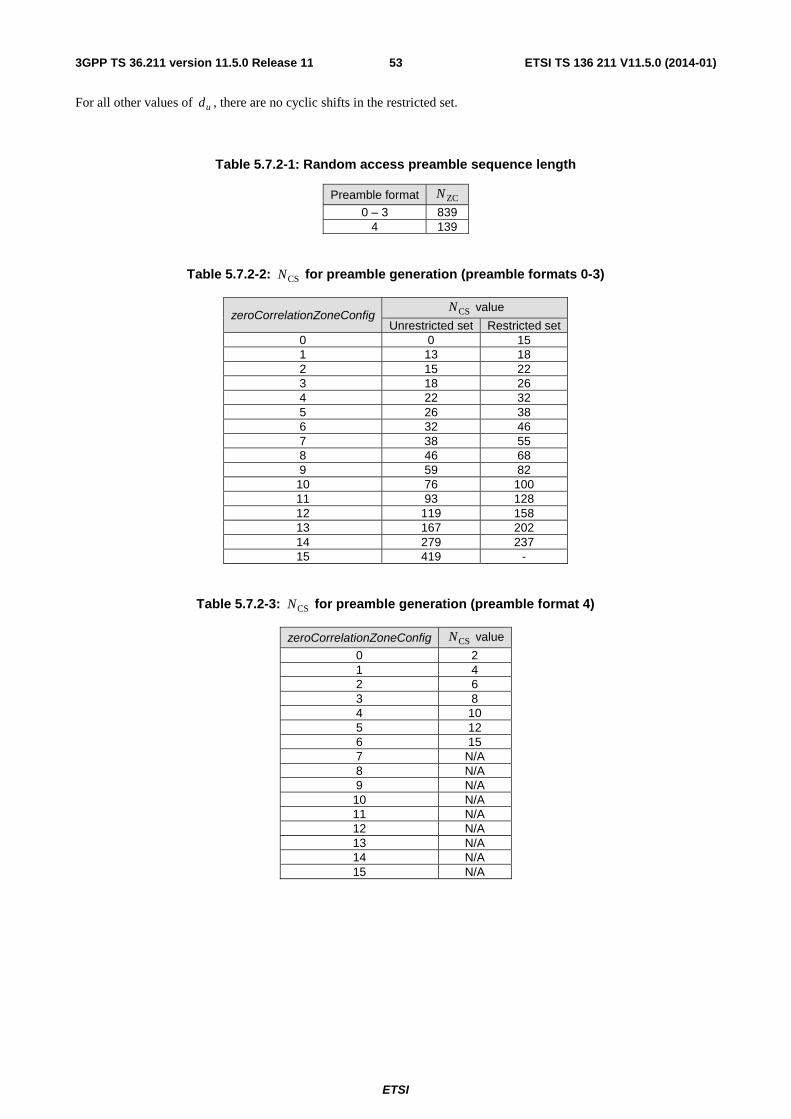
ETSI
ETSI TS 136 211 V11.5.0 (2014-01)533GPP TS 36.211 version 11.5.0 Release 11
For all other values of ud , there are no cyclic shifts in the restricted set.
Table 5.7.2-1: Random access preamble sequence length
Preamble format ZCN
0 – 3 839 4 139
Table 5.7.2-2: CSN for preamble generation (preamble formats 0-3)
zeroCorrelationZoneConfig CSN value
Unrestricted set Restricted set 0 0 15 1 13 18 2 15 22 3 18 26 4 22 32 5 26 38 6 32 46 7 38 55 8 46 68 9 59 82 10 76 100 11 93 128 12 119 158 13 167 202 14 279 237 15 419 -
Table 5.7.2-3: CSN for preamble generation (preamble format 4)
zeroCorrelationZoneConfig CSN value
0 2 1 4 2 6 3 8 4 10 5 12 6 15 7 N/A 8 N/A 9 N/A 10 N/A 11 N/A 12 N/A 13 N/A 14 N/A 15 N/A
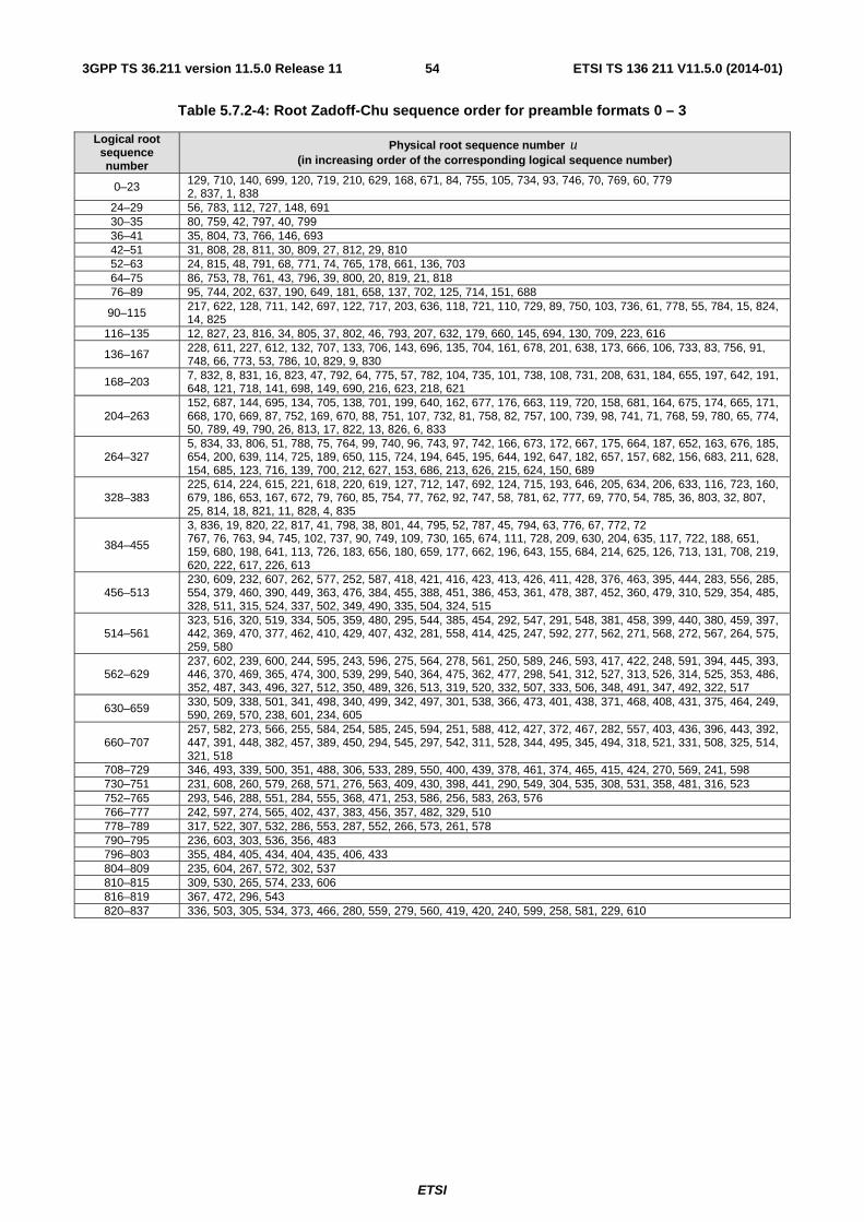
ETSI
ETSI TS 136 211 V11.5.0 (2014-01)543GPP TS 36.211 version 11.5.0 Release 11
Table 5.7.2-4: Root Zadoff-Chu sequence order for preamble formats 0 – 3
Logical root sequence number
Physical root sequence number u (in increasing order of the corresponding logical sequence number)
0–23 129, 710, 140, 699, 120, 719, 210, 629, 168, 671, 84, 755, 105, 734, 93, 746, 70, 769, 60, 779 2, 837, 1, 838
24–29 56, 783, 112, 727, 148, 691 30–35 80, 759, 42, 797, 40, 799 36–41 35, 804, 73, 766, 146, 693 42–51 31, 808, 28, 811, 30, 809, 27, 812, 29, 810 52–63 24, 815, 48, 791, 68, 771, 74, 765, 178, 661, 136, 703 64–75 86, 753, 78, 761, 43, 796, 39, 800, 20, 819, 21, 818 76–89 95, 744, 202, 637, 190, 649, 181, 658, 137, 702, 125, 714, 151, 688
90–115 217, 622, 128, 711, 142, 697, 122, 717, 203, 636, 118, 721, 110, 729, 89, 750, 103, 736, 61, 778, 55, 784, 15, 824, 14, 825
116–135 12, 827, 23, 816, 34, 805, 37, 802, 46, 793, 207, 632, 179, 660, 145, 694, 130, 709, 223, 616
136–167 228, 611, 227, 612, 132, 707, 133, 706, 143, 696, 135, 704, 161, 678, 201, 638, 173, 666, 106, 733, 83, 756, 91, 748, 66, 773, 53, 786, 10, 829, 9, 830
168–203 7, 832, 8, 831, 16, 823, 47, 792, 64, 775, 57, 782, 104, 735, 101, 738, 108, 731, 208, 631, 184, 655, 197, 642, 191, 648, 121, 718, 141, 698, 149, 690, 216, 623, 218, 621
204–263 152, 687, 144, 695, 134, 705, 138, 701, 199, 640, 162, 677, 176, 663, 119, 720, 158, 681, 164, 675, 174, 665, 171, 668, 170, 669, 87, 752, 169, 670, 88, 751, 107, 732, 81, 758, 82, 757, 100, 739, 98, 741, 71, 768, 59, 780, 65, 774, 50, 789, 49, 790, 26, 813, 17, 822, 13, 826, 6, 833
264–327 5, 834, 33, 806, 51, 788, 75, 764, 99, 740, 96, 743, 97, 742, 166, 673, 172, 667, 175, 664, 187, 652, 163, 676, 185, 654, 200, 639, 114, 725, 189, 650, 115, 724, 194, 645, 195, 644, 192, 647, 182, 657, 157, 682, 156, 683, 211, 628, 154, 685, 123, 716, 139, 700, 212, 627, 153, 686, 213, 626, 215, 624, 150, 689
328–383 225, 614, 224, 615, 221, 618, 220, 619, 127, 712, 147, 692, 124, 715, 193, 646, 205, 634, 206, 633, 116, 723, 160, 679, 186, 653, 167, 672, 79, 760, 85, 754, 77, 762, 92, 747, 58, 781, 62, 777, 69, 770, 54, 785, 36, 803, 32, 807, 25, 814, 18, 821, 11, 828, 4, 835
384–455
3, 836, 19, 820, 22, 817, 41, 798, 38, 801, 44, 795, 52, 787, 45, 794, 63, 776, 67, 772, 72 767, 76, 763, 94, 745, 102, 737, 90, 749, 109, 730, 165, 674, 111, 728, 209, 630, 204, 635, 117, 722, 188, 651, 159, 680, 198, 641, 113, 726, 183, 656, 180, 659, 177, 662, 196, 643, 155, 684, 214, 625, 126, 713, 131, 708, 219, 620, 222, 617, 226, 613
456–513 230, 609, 232, 607, 262, 577, 252, 587, 418, 421, 416, 423, 413, 426, 411, 428, 376, 463, 395, 444, 283, 556, 285, 554, 379, 460, 390, 449, 363, 476, 384, 455, 388, 451, 386, 453, 361, 478, 387, 452, 360, 479, 310, 529, 354, 485, 328, 511, 315, 524, 337, 502, 349, 490, 335, 504, 324, 515
514–561 323, 516, 320, 519, 334, 505, 359, 480, 295, 544, 385, 454, 292, 547, 291, 548, 381, 458, 399, 440, 380, 459, 397, 442, 369, 470, 377, 462, 410, 429, 407, 432, 281, 558, 414, 425, 247, 592, 277, 562, 271, 568, 272, 567, 264, 575, 259, 580
562–629 237, 602, 239, 600, 244, 595, 243, 596, 275, 564, 278, 561, 250, 589, 246, 593, 417, 422, 248, 591, 394, 445, 393, 446, 370, 469, 365, 474, 300, 539, 299, 540, 364, 475, 362, 477, 298, 541, 312, 527, 313, 526, 314, 525, 353, 486, 352, 487, 343, 496, 327, 512, 350, 489, 326, 513, 319, 520, 332, 507, 333, 506, 348, 491, 347, 492, 322, 517
630–659 330, 509, 338, 501, 341, 498, 340, 499, 342, 497, 301, 538, 366, 473, 401, 438, 371, 468, 408, 431, 375, 464, 249, 590, 269, 570, 238, 601, 234, 605
660–707 257, 582, 273, 566, 255, 584, 254, 585, 245, 594, 251, 588, 412, 427, 372, 467, 282, 557, 403, 436, 396, 443, 392, 447, 391, 448, 382, 457, 389, 450, 294, 545, 297, 542, 311, 528, 344, 495, 345, 494, 318, 521, 331, 508, 325, 514, 321, 518
708–729 346, 493, 339, 500, 351, 488, 306, 533, 289, 550, 400, 439, 378, 461, 374, 465, 415, 424, 270, 569, 241, 598 730–751 231, 608, 260, 579, 268, 571, 276, 563, 409, 430, 398, 441, 290, 549, 304, 535, 308, 531, 358, 481, 316, 523 752–765 293, 546, 288, 551, 284, 555, 368, 471, 253, 586, 256, 583, 263, 576 766–777 242, 597, 274, 565, 402, 437, 383, 456, 357, 482, 329, 510 778–789 317, 522, 307, 532, 286, 553, 287, 552, 266, 573, 261, 578 790–795 236, 603, 303, 536, 356, 483 796–803 355, 484, 405, 434, 404, 435, 406, 433 804–809 235, 604, 267, 572, 302, 537 810–815 309, 530, 265, 574, 233, 606 816–819 367, 472, 296, 543 820–837 336, 503, 305, 534, 373, 466, 280, 559, 279, 560, 419, 420, 240, 599, 258, 581, 229, 610
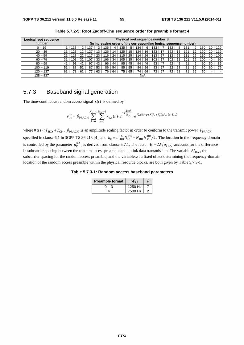
ETSI
ETSI TS 136 211 V11.5.0 (2014-01)553GPP TS 36.211 version 11.5.0 Release 11
Table 5.7.2-5: Root Zadoff-Chu sequence order for preamble format 4
Logical root sequence number
Physical root sequence number u (in increasing order of the corresponding logical sequence number)
0 – 19 1 138 2 137 3 136 4 135 5 134 6 133 7 132 8 131 9 130 10 129 20 – 39 11 128 12 127 13 126 14 125 15 124 16 123 17 122 18 121 19 120 20 119 40 – 59 21 118 22 117 23 116 24 115 25 114 26 113 27 112 28 111 29 110 30 109 60 – 79 31 108 32 107 33 106 34 105 35 104 36 103 37 102 38 101 39 100 40 99 80 – 99 41 98 42 97 43 96 44 95 45 94 46 93 47 92 48 91 49 90 50 89
100 – 119 51 88 52 87 53 86 54 85 55 84 56 83 57 82 58 81 59 80 60 79 120 – 137 61 78 62 77 63 76 64 75 65 74 66 73 67 72 68 71 69 70 - - 138 – 837 N/A
5.7.3 Baseband signal generation
The time-continuous random access signal )(ts is defined by
( ) ( )( ) ( )∑ ∑
−
=
−Δ+++−
=
−⋅⋅=
1
0
21
0
2
,PRACH
ZC
CPRA21
0
ZC
ZC)(N
k
TtfkKkjN
n
N
nkj
vu eenxts ϕππ
β
where CPSEQ0 TTt +<≤ , PRACHβ is an amplitude scaling factor in order to conform to the transmit power PRACHP
specified in clause 6.1 in 3GPP TS 36.213 [4], and 2RBsc
ULRB
RBsc
RAPRB0 NNNnk −= . The location in the frequency domain
is controlled by the parameter RAPRBn is derived from clause 5.7.1. The factor RAffK ΔΔ= accounts for the difference
in subcarrier spacing between the random access preamble and uplink data transmission. The variable RAfΔ , the
subcarrier spacing for the random access preamble, and the variableϕ , a fixed offset determining the frequency-domain
location of the random access preamble within the physical resource blocks, are both given by Table 5.7.3-1.
Table 5.7.3-1: Random access baseband parameters
Preamble format RAfΔ ϕ
0 – 3 1250 Hz 7 4 7500 Hz 2
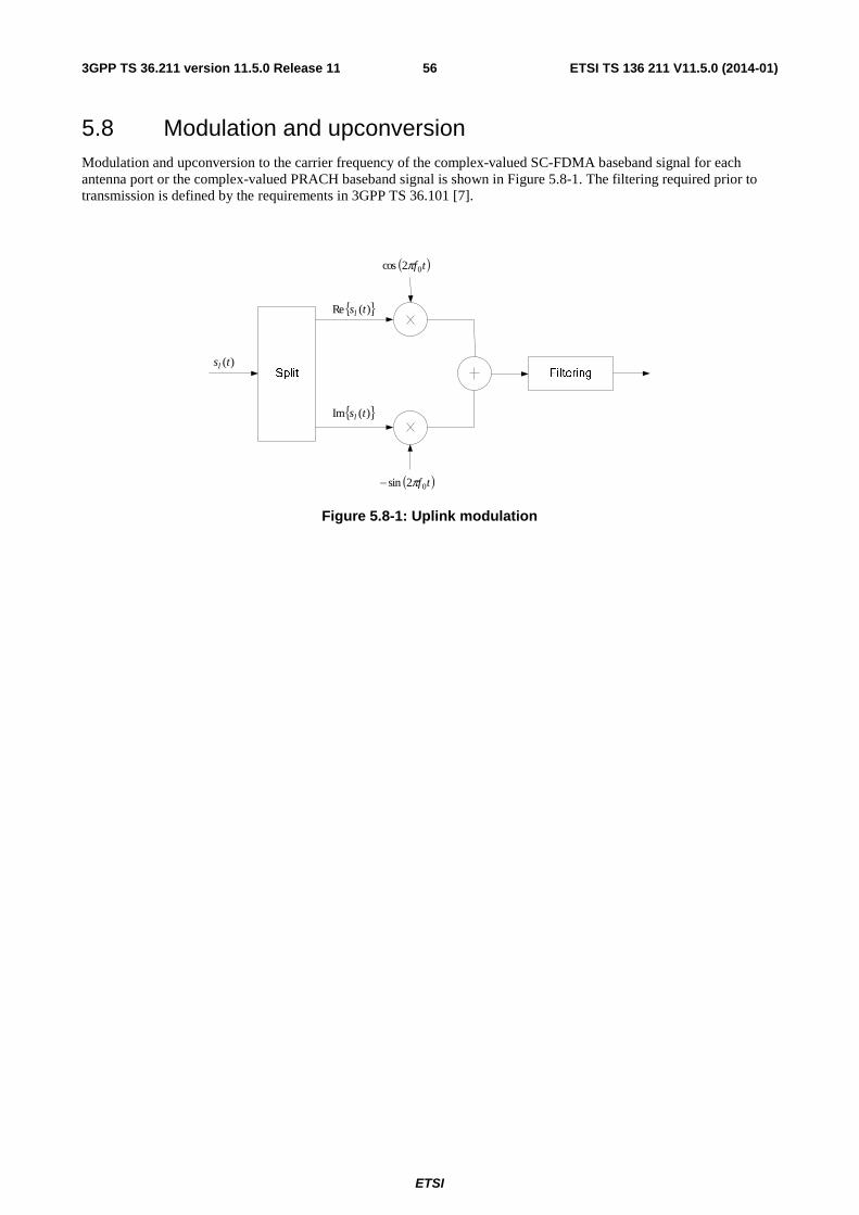
ETSI
ETSI TS 136 211 V11.5.0 (2014-01)563GPP TS 36.211 version 11.5.0 Release 11
5.8 Modulation and upconversion Modulation and upconversion to the carrier frequency of the complex-valued SC-FDMA baseband signal for each antenna port or the complex-valued PRACH baseband signal is shown in Figure 5.8-1. The filtering required prior to transmission is defined by the requirements in 3GPP TS 36.101 [7].
{ })(Re tsl
{ })(Im tsl
( )tf02cos π
( )tf02sin π−
)(tsl
Figure 5.8-1: Uplink modulation
ETSI
ETSI TS 136 211 V11.5.0 (2014-01)573GPP TS 36.211 version 11.5.0 Release 11
6 Downlink
6.1 Overview The smallest time-frequency unit for downlink transmission is denoted a resource element and is defined in clause 6.2.2.
A subset of the downlink subframes in a radio frame on a carrier supporting PDSCH transmission can be configured as MBSFN subframes by higher layers. Each MBSFN subframe is divided into a non-MBSFN region and an MBSFN region.
- The non-MBSFN region spans the first one or two OFDM symbols in an MBSFN subframe where the length of the non-MBSFN region is given according to Subclause 6.7.
- The MBSFN region in an MBSFN subframe is defined as the OFDM symbols not used for the non-MBSFN region.
Unless otherwise specified, transmission in each downlink subframe shall use the same cyclic prefix length as used for downlink subframe #0.
6.1.1 Physical channels
A downlink physical channel corresponds to a set of resource elements carrying information originating from higher layers and is the interface defined between 3GPP TS 36.212 [3] and the present document 3GPP TS 36.211. The following downlink physical channels are defined:
- Physical Downlink Shared Channel, PDSCH
- Physical Broadcast Channel, PBCH
- Physical Multicast Channel, PMCH
- Physical Control Format Indicator Channel, PCFICH
- Physical Downlink Control Channel, PDCCH
- Physical Hybrid ARQ Indicator Channel, PHICH
- Enhanced Physical Downlink Control Channel, EPDCCH
6.1.2 Physical signals
A downlink physical signal corresponds to a set of resource elements used by the physical layer but does not carry information originating from higher layers. The following downlink physical signals are defined:
- Reference signal
- Synchronization signal
ETSI
ETSI TS 136 211 V11.5.0 (2014-01)583GPP TS 36.211 version 11.5.0 Release 11
6.2 Slot structure and physical resource elements
6.2.1 Resource grid
The transmitted signal in each slot is described by one or several resource grids of RBsc
DLRB NN subcarriers and DL
symbN
OFDM symbols. The resource grid structure is illustrated in Figure 6.2.2-1. The quantity DLRBN depends on the
downlink transmission bandwidth configured in the cell and shall fulfil
DLmax,RB
DLRB
DLmin,RB NNN ≤≤
where 6DLmin,RB =N and 110DLmax,
RB =N are the smallest and largest downlink bandwidths, respectively, supported by
the current version of this specification.
The set of allowed values for DLRBN is given by 3GPP TS 36.104 [6]. The number of OFDM symbols in a slot depends
on the cyclic prefix length and subcarrier spacing configured and is given in Table 6.2.3-1.
An antenna port is defined such that the channel over which a symbol on the antenna port is conveyed can be inferred from the channel over which another symbol on the same antenna port is conveyed. There is one resource grid per antenna port. The set of antenna ports supported depends on the reference signal configuration in the cell:
- Cell-specific reference signals support a configuration of one, two, or four antenna ports and are transmitted on antenna ports 0=p , { }1,0∈p , and { }3,2,1,0∈p , respectively.
- MBSFN reference signals are transmitted on antenna port 4=p .
- UE-specific reference signals associated with PDSCH are transmitted on antenna port(s) 5=p , 7=p , 8=p ,
or one or several of { }14,13,12,11,10,9,8,7∈p .
- Demodulation reference signals associated with EPDCCH are transmitted on one or several of { }110,109,108,107∈p .
- Positioning reference signals are transmitted on antenna port 6=p .
- CSI reference signals support a configuration of one, two, four or eight antenna ports and are transmitted on antenna ports 15=p , 16,15=p , 18,...,15=p and 22,...,15=p , respectively.
Two antenna ports are said to be quasi co-located if the large-scale properties of the channel over which a symbol on one antenna port is conveyed can be inferred from the channel over which a symbol on the other antenna port is conveyed. The large-scale properties include one or more of delay spread, Doppler spread, Doppler shift, average gain, and average delay.
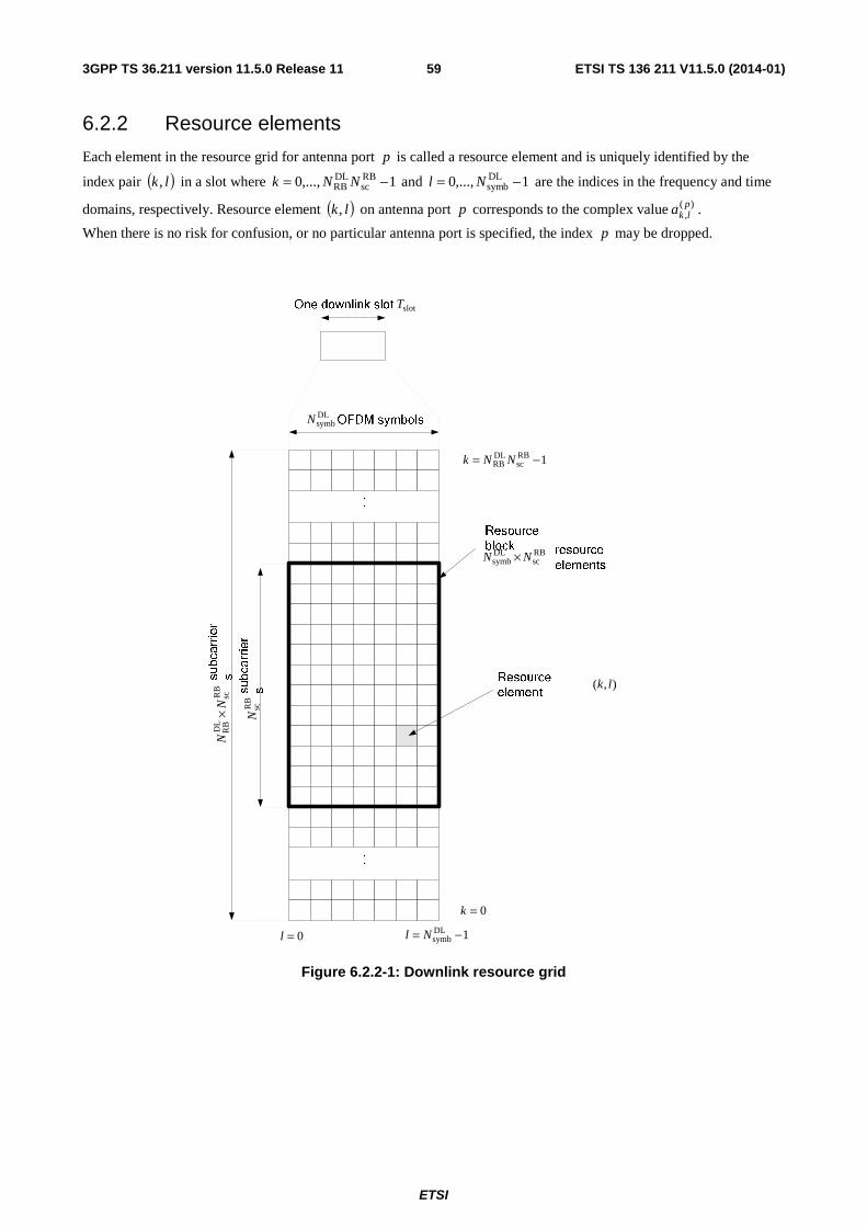
ETSI
ETSI TS 136 211 V11.5.0 (2014-01)593GPP TS 36.211 version 11.5.0 Release 11
6.2.2 Resource elements
Each element in the resource grid for antenna port p is called a resource element and is uniquely identified by the
index pair ( )lk, in a slot where 1,...,0 RBsc
DLRB −= NNk and 1,...,0 DL
symb −= Nl are the indices in the frequency and time
domains, respectively. Resource element ( )lk, on antenna port p corresponds to the complex value )(,plka .
When there is no risk for confusion, or no particular antenna port is specified, the index p may be dropped.
DLsymbN
slotT
0=l 1DLsymb −= Nl
RB
scD
LR
BN
N×
RB
scN
RBsc
DLsymb NN ×
),( lk
0=k
1RBsc
DLRB −= NNk
Figure 6.2.2-1: Downlink resource grid
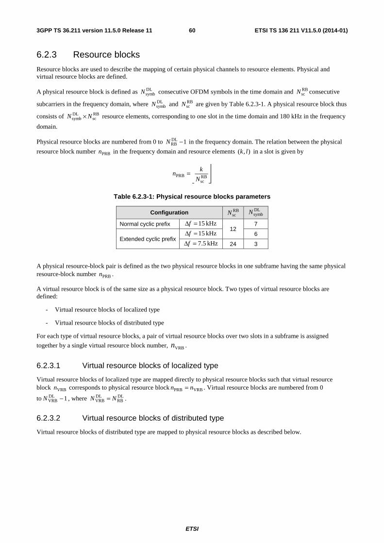
ETSI
ETSI TS 136 211 V11.5.0 (2014-01)603GPP TS 36.211 version 11.5.0 Release 11
6.2.3 Resource blocks
Resource blocks are used to describe the mapping of certain physical channels to resource elements. Physical and virtual resource blocks are defined.
A physical resource block is defined as DLsymbN consecutive OFDM symbols in the time domain and RB
scN consecutive
subcarriers in the frequency domain, where DLsymbN and RB
scN are given by Table 6.2.3-1. A physical resource block thus
consists of RBsc
DLsymb NN × resource elements, corresponding to one slot in the time domain and 180 kHz in the frequency
domain.
Physical resource blocks are numbered from 0 to 1DLRB −N in the frequency domain. The relation between the physical
resource block number PRBn in the frequency domain and resource elements ),( lk in a slot is given by
⎥⎥⎦
⎥
⎢⎢⎣
⎢=
RBsc
PRBN
kn
Table 6.2.3-1: Physical resource blocks parameters
Configuration RBscN
DLsymbN
Normal cyclic prefix kHz 15=Δf
12 7
Extended cyclic prefix kHz 15=Δf 6
kHz 5.7=Δf 24 3
A physical resource-block pair is defined as the two physical resource blocks in one subframe having the same physical resource-block number PRBn .
A virtual resource block is of the same size as a physical resource block. Two types of virtual resource blocks are defined:
- Virtual resource blocks of localized type
- Virtual resource blocks of distributed type
For each type of virtual resource blocks, a pair of virtual resource blocks over two slots in a subframe is assigned
together by a single virtual resource block number, VRBn .
6.2.3.1 Virtual resource blocks of localized type
Virtual resource blocks of localized type are mapped directly to physical resource blocks such that virtual resource block VRBn corresponds to physical resource block VRBPRB nn = . Virtual resource blocks are numbered from 0
to 1DLVRB −N , where DL
RBDLVRB NN = .
6.2.3.2 Virtual resource blocks of distributed type
Virtual resource blocks of distributed type are mapped to physical resource blocks as described below.
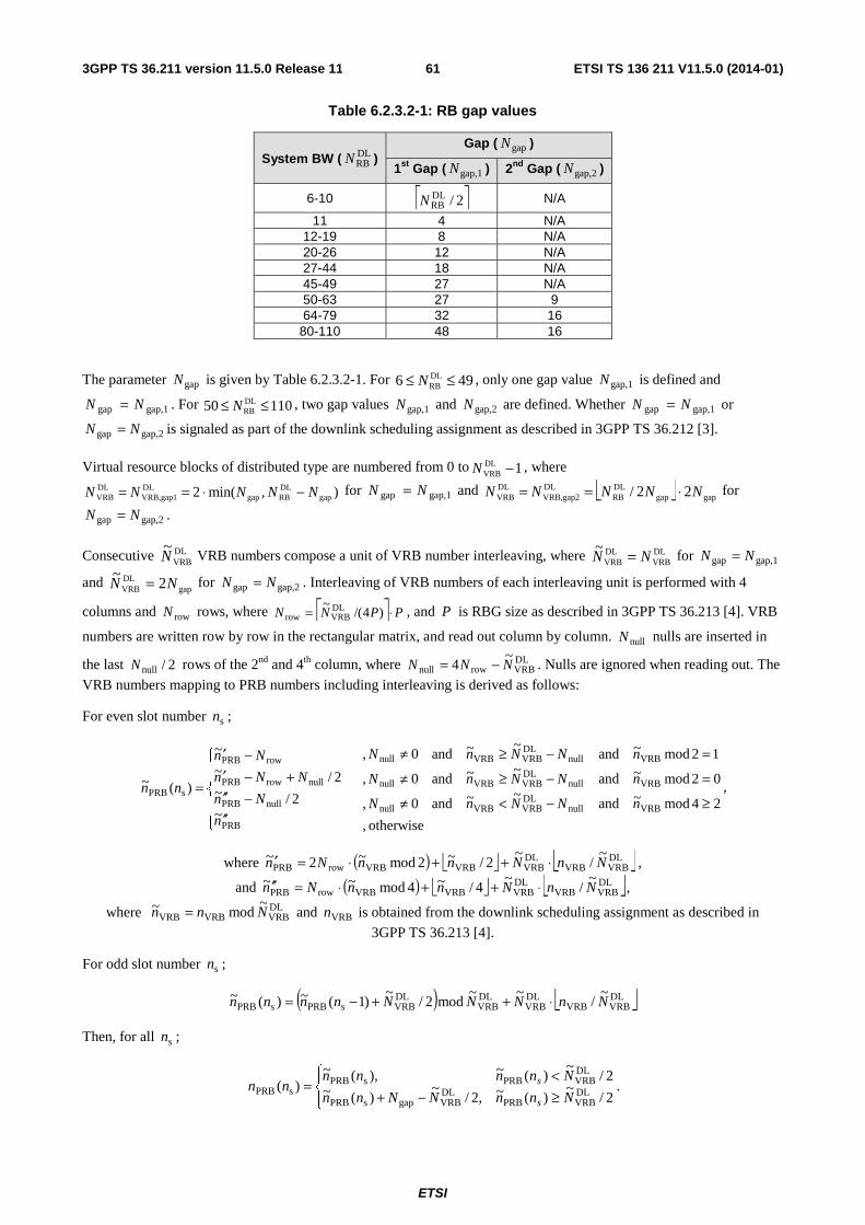
ETSI
ETSI TS 136 211 V11.5.0 (2014-01)613GPP TS 36.211 version 11.5.0 Release 11
Table 6.2.3.2-1: RB gap values
System BW ( DLRBN )
Gap ( gapN )
1st Gap ( gap,1N ) 2nd Gap ( gap,2N )
6-10 ⎡ ⎤2/DLRBN N/A
11 4 N/A 12-19 8 N/A 20-26 12 N/A 27-44 18 N/A 45-49 27 N/A 50-63 27 9 64-79 32 16
80-110 48 16
The parameter gapN is given by Table 6.2.3.2-1. For 496 DLRB ≤≤ N , only one gap value gap,1N is defined and
gap,1gap NN = . For 11050 DLRB ≤≤ N , two gap values gap,1N and gap,2N are defined. Whether gap,1gap NN = or
gap,2gap NN = is signaled as part of the downlink scheduling assignment as described in 3GPP TS 36.212 [3].
Virtual resource blocks of distributed type are numbered from 0 to 1DLVRB −N , where
),min(2 gapDLRBgap
DLgap1VRB,
DLVRB NNNNN −⋅== for gap,1gap NN = and ⎣ ⎦ gapgap
DLRB
DLgap2VRB,
DLVRB 22/ NNNNN ⋅== for
gap,2gap NN = .
Consecutive DLVRB
~N VRB numbers compose a unit of VRB number interleaving, where DL
VRBDLVRB
~NN = for gap,1gap NN =
and gap
DLVRB 2
~NN = for gap,2gap NN = . Interleaving of VRB numbers of each interleaving unit is performed with 4
columns and rowN rows, where ⎡ ⎤ PPNN ⋅= )4/(~ DL
VRBrow , and P is RBG size as described in 3GPP TS 36.213 [4]. VRB
numbers are written row by row in the rectangular matrix, and read out column by column. nullN nulls are inserted in
the last 2/nullN rows of the 2nd and 4th column, where DLVRBrownull
~4 NNN −= . Nulls are ignored when reading out. The
VRB numbers mapping to PRB numbers including interleaving is derived as follows:
For even slot number sn ;
otherwise ,
24mod~and~~and0,
02mod~and~~and0,
12mod~and~~and0,
~2/~
2/~
~
)(~
VRBnullDLVRBVRBnull
VRBnullDLVRBVRBnull
VRBnullDLVRBVRBnull
PRB
nullPRB
nullrowPRB
rowPRB
sPRB≥−<≠
=−≥≠
=−≥≠
⎪⎪
⎩
⎪⎪
⎨
⎧
′′−′′
+−′−′
=nNNnN
nNNnN
nNNnN
n
Nn
NNn
Nn
nn ,
where ( ) ⎣ ⎦ ⎣ ⎦DLVRBVRB
DLVRBVRBVRBrowPRB
~/
~2/~2mod~2~ NnNnnNn ⋅++⋅=′ ,
and ( ) ⎣ ⎦ ⎣ ⎦DLVRBVRB
DLVRBVRBVRBrowPRB
~/
~4/~4mod~~ NnNnnNn ⋅++⋅=′′ ,
where DLVRBVRBVRB
~mod~ Nnn = and VRBn is obtained from the downlink scheduling assignment as described in
3GPP TS 36.213 [4].
For odd slot number sn ;
( ) ⎣ ⎦DLVRBVRB
DLVRB
DLVRB
DLVRBsPRBsPRB
~/
~~mod2/
~)1(~)(~ NnNNNnnnn ⋅++−=
Then, for all sn ;
⎪⎩
⎪⎨⎧
≥−+<
=2/
~)(~,2/
~)(~
2/~
)(~),(~)( DL
VRBPRBDLVRBgapsPRB
DLVRBPRBsPRB
sPRB NnnNNnn
Nnnnnnn
s
s .
ETSI
ETSI TS 136 211 V11.5.0 (2014-01)623GPP TS 36.211 version 11.5.0 Release 11
6.2.4 Resource-element groups
Resource-element groups are used for defining the mapping of control channels to resource elements.
A resource-element group is represented by the index pair ),( lk ′′ of the resource element with the lowest index k in
the group with all resource elements in the group having the same value of l . The set of resource elements ),( lk in a
resource-element group depends on the number of cell-specific reference signals configured as described below with RBscPRB0 Nnk ⋅= , DL
RBPRB0 Nn <≤ .
- In the first OFDM symbol of the first slot in a subframe the two resource-element groups in physical resource block PRBn consist of resource elements )0,( =lk with 5 ,...,1 ,0 000 +++= kkkk and
11 ,...,7 ,6 000 +++= kkkk , respectively.
- In the second OFDM symbol of the first slot in a subframe in case of one or two cell-specific reference signals configured, the three resource-element groups in physical resource block PRBn consist of resource elements
)1,( =lk with 3 ,...,1 ,0 000 +++= kkkk , 7 ,...,5 ,4 000 +++= kkkk and 11 ,...,9 ,8 000 +++= kkkk ,
respectively.
- In the second OFDM symbol of the first slot in a subframe in case of four cell-specific reference signals configured, the two resource-element groups in physical resource block PRBn consist of resource elements
)1,( =lk with 5 ,...,1 ,0 000 +++= kkkk and 11 ,...,7 ,6 000 +++= kkkk , respectively.
- In the third OFDM symbol of the first slot in a subframe, the three resource-element groups in physical resource block PRBn consist of resource elements )2,( =lk with 3 ,...,1 ,0 000 +++= kkkk , 7 ,...,5 ,4 000 +++= kkkk
and 11 ,...,9 ,8 000 +++= kkkk , respectively.
- In the fourth OFDM symbol of the first slot in a subframe in case of normal cyclic prefix, the three resource-element groups in physical resource block PRBn consist of resource elements )3,( =lk with
3 ,...,1 ,0 000 +++= kkkk , 7 ,...,5 ,4 000 +++= kkkk and 11 ,...,9 ,8 000 +++= kkkk , respectively.
- In the fourth OFDM symbol of the first slot in a subframe in case of extended cyclic prefix, the two resource-element groups in physical resource block PRBn consist of resource elements )3,( =lk with
5 ,...,1 ,0 000 +++= kkkk and 11 ,...,7 ,6 000 +++= kkkk , respectively.
Mapping of a symbol-quadruplet )3(),2(),1(),( +++ iziziziz onto a resource-element group represented by resource-
element ),( lk ′′ is defined such that elements )(iz are mapped to resource elements ),( lk of the resource-element
group not used for cell-specific reference signals in increasing order of i and k . In case a single cell-specific reference signal is configured, cell-specific reference signals shall be assumed to be present on antenna ports 0 and 1 for the purpose of mapping a symbol-quadruplet to a resource-element group, otherwise the number of cell-specific reference signals shall be assumed equal to the actual number of antenna ports used for cell-specific reference signals. The UE shall not make any assumptions about resource elements assumed to be reserved for reference signals but not used for transmission of a reference signal.
ETSI
ETSI TS 136 211 V11.5.0 (2014-01)633GPP TS 36.211 version 11.5.0 Release 11
6.2.4A Enhanced Resource-Element Groups (EREGs)
EREGs are used for defining the mapping of enhanced control channels to resource elements.
There are 16 EREGs, numbered from 0 to 15, per physical resource block pair. Number all resource elements, except resource elements carrying DM-RS for antenna ports { }110,109,108,107=p for normal cyclic prefix or { }108,107=p
for extended cyclic prefix, in a physical resource-block pair cyclically from 0 to 15 in an increasing order of first frequency, then time. All resource elements with number i in that physical resource-block pair constitutes EREG number i .
6.2.5 Guard period for half-duplex FDD operation
For half-duplex FDD operation, a guard period is created by the UE by not receiving the last part of a downlink subframe immediately preceding an uplink subframe from the same UE.
6.2.6 Guard Period for TDD Operation
For frame structure type 2, the GP field in Figure 4.2-1 serves as a guard period.
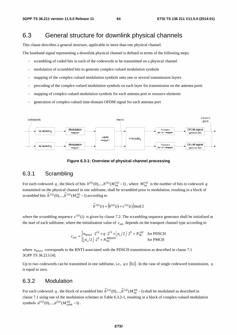
ETSI
ETSI TS 136 211 V11.5.0 (2014-01)643GPP TS 36.211 version 11.5.0 Release 11
6.3 General structure for downlink physical channels This clause describes a general structure, applicable to more than one physical channel.
The baseband signal representing a downlink physical channel is defined in terms of the following steps:
- scrambling of coded bits in each of the codewords to be transmitted on a physical channel
- modulation of scrambled bits to generate complex-valued modulation symbols
- mapping of the complex-valued modulation symbols onto one or several transmission layers
- precoding of the complex-valued modulation symbols on each layer for transmission on the antenna ports
- mapping of complex-valued modulation symbols for each antenna port to resource elements
- generation of complex-valued time-domain OFDM signal for each antenna port
Figure 6.3-1: Overview of physical channel processing
6.3.1 Scrambling
For each codeword q , the block of bits )1(),...,0( )(bit
)()( −qqq Mbb , where )(bitqM is the number of bits in codeword q
transmitted on the physical channel in one subframe, shall be scrambled prior to modulation, resulting in a block of
scrambled bits )1(~
),...,0(~ (q)
bit)()( −Mbb qq according to
( ) 2mod)()()(~ )()()( icibib qqq +=
where the scrambling sequence )()( ic q is given by clause 7.2. The scrambling sequence generator shall be initialised at
the start of each subframe, where the initialisation value of initc depends on the transport channel type according to
⎣ ⎦⎣ ⎦⎪⎩
⎪⎨⎧
+⋅+⋅+⋅+⋅=
PMCHfor 22
PDSCHfor 2222MBSFNID
9s
cellID
9s
1314RNTI
initNn
Nnqnc
where RNTIn corresponds to the RNTI associated with the PDSCH transmission as described in clause 7.1
3GPP TS 36.213 [4].
Up to two codewords can be transmitted in one subframe, i.e., { }1,0∈q . In the case of single codeword transmission, q
is equal to zero.
6.3.2 Modulation
For each codeword q , the block of scrambled bits )1(~
),...,0(~ (q)
bit)()( −Mbb qq shall be modulated as described in
clause 7.1 using one of the modulation schemes in Table 6.3.2-1, resulting in a block of complex-valued modulation
symbols )1(),...,0( (q)symb
)()( −Mdd qq .
ETSI
ETSI TS 136 211 V11.5.0 (2014-01)653GPP TS 36.211 version 11.5.0 Release 11
Table 6.3.2-1: Modulation schemes
Physical channel Modulation schemes PDSCH QPSK, 16QAM, 64QAM PMCH QPSK, 16QAM, 64QAM
6.3.3 Layer mapping
The complex-valued modulation symbols for each of the codewords to be transmitted are mapped onto one or several
layers. Complex-valued modulation symbols )1(),...,0( (q)symb
)()( −Mdd qq for codeword q shall be mapped onto the
layers [ ]Tixixix )(...)()( )1()0( −= υ , 1,...,1,0 layersymb −= Mi where υ is the number of layers and layer
symbM is the number of
modulation symbols per layer.
6.3.3.1 Layer mapping for transmission on a single antenna port
For transmission on a single antenna port, a single layer is used, 1=υ , and the mapping is defined by
)()( )0()0( idix =
with (0)symb
layersymb MM = .
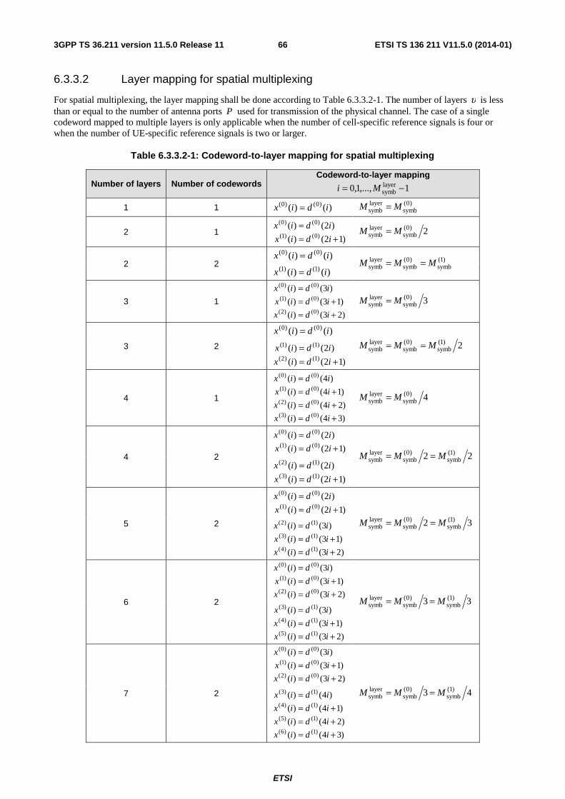
ETSI
ETSI TS 136 211 V11.5.0 (2014-01)663GPP TS 36.211 version 11.5.0 Release 11
6.3.3.2 Layer mapping for spatial multiplexing
For spatial multiplexing, the layer mapping shall be done according to Table 6.3.3.2-1. The number of layers υ is less than or equal to the number of antenna ports P used for transmission of the physical channel. The case of a single codeword mapped to multiple layers is only applicable when the number of cell-specific reference signals is four or when the number of UE-specific reference signals is two or larger.
Table 6.3.3.2-1: Codeword-to-layer mapping for spatial multiplexing
Number of layers Number of codewords Codeword-to-layer mapping
1,...,1,0 layersymb −= Mi
1 1 )()( )0()0( idix = )0(
symblayersymb MM =
2 1 )12()(
)2()()0()1(
)0()0(
+==
idix
idix 2)0(
symblayersymb MM =
2 2 )()( )0()0( idix = )1(
symb)0(
symblayersymb MMM ==
)()( )1()1( idix =
3 1
)23()(
)13()(
)3()(
)0()2(
)0()1(
)0()0(
+=+=
=
idix
idix
idix 3)0(
symblayersymb MM =
3 2
)()( )0()0( idix =
2)1(symb
)0(symb
layersymb MMM ==
)12()(
)2()()1()2(
)1()1(
+==
idix
idix
4 1
)34()(
)24()(
)14()(
)4()(
)0()3(
)0()2(
)0()1(
)0()0(
+=+=+=
=
idix
idix
idix
idix
4)0(symb
layersymb MM =
4 2 )12()(
)2()()0()1(
)0()0(
+==
idix
idix
22 )1(symb
)0(symb
layersymb MMM ==
)12()(
)2()()1()3(
)1()2(
+==
idix
idix
5 2
)12()(
)2()()0()1(
)0()0(
+==
idix
idix
32 )1(symb
)0(symb
layersymb MMM ==
)23()(
)13()(
)3()(
)1()4(
)1()3(
)1()2(
+=+=
=
idix
idix
idix
6 2 )23()(
)13()(
)3()(
)0()2(
)0()1(
)0()0(
+=+=
=
idix
idix
idix
33 )1(symb
)0(symb
layersymb MMM ==
)23()(
)13()(
)3()(
)1()5(
)1()4(
)1()3(
+=+=
=
idix
idix
idix
7 2
)23()(
)13()(
)3()(
)0()2(
)0()1(
)0()0(
+=+=
=
idix
idix
idix
43 )1(symb
)0(symb
layersymb MMM ==
)34()(
)24()(
)14()(
)4()(
)1()6(
)1()5(
)1()4(
)1()3(
+=+=+=
=
idix
idix
idix
idix
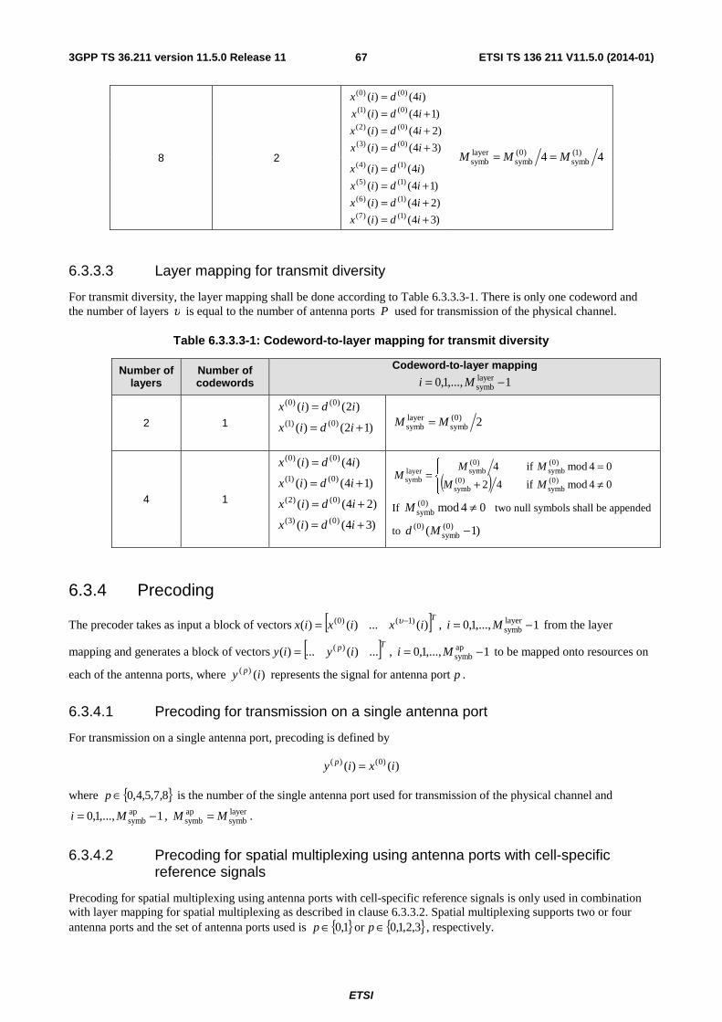
ETSI
ETSI TS 136 211 V11.5.0 (2014-01)673GPP TS 36.211 version 11.5.0 Release 11
8 2 )34()(
)24()(
)14()(
)4()(
)0()3(
)0()2(
)0()1(
)0()0(
+=+=+=
=
idix
idix
idix
idix
44 )1(symb
)0(symb
layersymb MMM ==
)34()(
)24()(
)14()(
)4()(
)1()7(
)1()6(
)1()5(
)1()4(
+=+=+=
=
idix
idix
idix
idix
6.3.3.3 Layer mapping for transmit diversity
For transmit diversity, the layer mapping shall be done according to Table 6.3.3.3-1. There is only one codeword and the number of layers υ is equal to the number of antenna ports P used for transmission of the physical channel.
Table 6.3.3.3-1: Codeword-to-layer mapping for transmit diversity
Number of layers
Number of codewords
Codeword-to-layer mapping
1,...,1,0 layersymb −= Mi
2 1 )12()(
)2()()0()1(
)0()0(
+=
=
idix
idix
2)0(symb
layersymb MM =
4 1
)34()(
)24()(
)14()(
)4()(
)0()3(
)0()2(
)0()1(
)0()0(
+=
+=
+=
=
idix
idix
idix
idix
( )⎪⎩
⎪⎨⎧
≠+=
=04mod if 42
04mod if4)0(
symb)0(
symb
)0(symb
)0(symblayer
symb MM
MMM
If 04mod)0(symb ≠M two null symbols shall be appended
to )1( )0(symb
)0( −Md
6.3.4 Precoding
The precoder takes as input a block of vectors [ ]Tixixix )(...)()( )1()0( −= υ , 1,...,1,0 layersymb −= Mi from the layer
mapping and generates a block of vectors [ ]Tp iyiy ...)(...)( )(= , 1,...,1,0 apsymb −= Mi to be mapped onto resources on
each of the antenna ports, where )()( iy p represents the signal for antenna port p .
6.3.4.1 Precoding for transmission on a single antenna port
For transmission on a single antenna port, precoding is defined by
)()( )0()( ixiy p =
where { }8,7,5,4,0∈p is the number of the single antenna port used for transmission of the physical channel and
1,...,1,0 apsymb −= Mi , layer
symbapsymb MM = .
6.3.4.2 Precoding for spatial multiplexing using antenna ports with cell-specific reference signals
Precoding for spatial multiplexing using antenna ports with cell-specific reference signals is only used in combination with layer mapping for spatial multiplexing as described in clause 6.3.3.2. Spatial multiplexing supports two or four antenna ports and the set of antenna ports used is { }1,0∈p or { }3,2,1,0∈p , respectively.
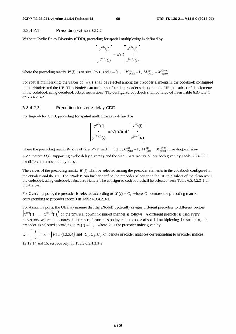
ETSI
ETSI TS 136 211 V11.5.0 (2014-01)683GPP TS 36.211 version 11.5.0 Release 11
6.3.4.2.1 Precoding without CDD
Without Cyclic Delay Diversity (CDD), precoding for spatial multiplexing is defined by
⎥⎥⎥
⎦
⎤
⎢⎢⎢
⎣
⎡
=⎥⎥⎥
⎦
⎤
⎢⎢⎢
⎣
⎡
−− )(
)(
)(
)(
)(
)1(
)0(
)1(
)0(
ix
ix
iW
iy
iy
P υMM
where the precoding matrix )(iW is of size υ×P and 1,...,1,0 apsymb −= Mi , layer
symbapsymb MM = .
For spatial multiplexing, the values of )(iW shall be selected among the precoder elements in the codebook configured
in the eNodeB and the UE. The eNodeB can further confine the precoder selection in the UE to a subset of the elements in the codebook using codebook subset restrictions. The configured codebook shall be selected from Table 6.3.4.2.3-1 or 6.3.4.2.3-2.
6.3.4.2.2 Precoding for large delay CDD
For large-delay CDD, precoding for spatial multiplexing is defined by
⎥⎥⎥
⎦
⎤
⎢⎢⎢
⎣
⎡
=⎥⎥⎥
⎦
⎤
⎢⎢⎢
⎣
⎡
−− )(
)(
)()(
)(
)(
)1(
)0(
)1(
)0(
ix
ix
UiDiW
iy
iy
P υMM
where the precoding matrix )(iW is of size υ×P and 1,...,1,0 apsymb −= Mi , layer
symbapsymb MM = . The diagonal size-
υυ × matrix )(iD supporting cyclic delay diversity and the size- υυ × matrix U are both given by Table 6.3.4.2.2-1
for different numbers of layers υ .
The values of the precoding matrix )(iW shall be selected among the precoder elements in the codebook configured in
the eNodeB and the UE. The eNodeB can further confine the precoder selection in the UE to a subset of the elements in the codebook using codebook subset restriction. The configured codebook shall be selected from Table 6.3.4.2.3-1 or 6.3.4.2.3-2.
For 2 antenna ports, the precoder is selected according to 1)( CiW = where 1C denotes the precoding matrix
corresponding to precoder index 0 in Table 6.3.4.2.3-1.
For 4 antenna ports, the UE may assume that the eNodeB cyclically assigns different precoders to different vectors
[ ]Tixix )(...)( )1()0( −υ on the physical downlink shared channel as follows. A different precoder is used every
υ vectors, where υ denotes the number of transmission layers in the case of spatial multiplexing. In particular, the precoder is selected according to kCiW =)( , where k is the precoder index given by
{ }4,3,2,114mod ∈+⎟⎟⎠
⎞⎜⎜⎝
⎛⎥⎦
⎥⎢⎣
⎢=υi
k and 4321 ,,, CCCC denote precoder matrices corresponding to precoder indices
12,13,14 and 15, respectively, in Table 6.3.4.2.3-2.
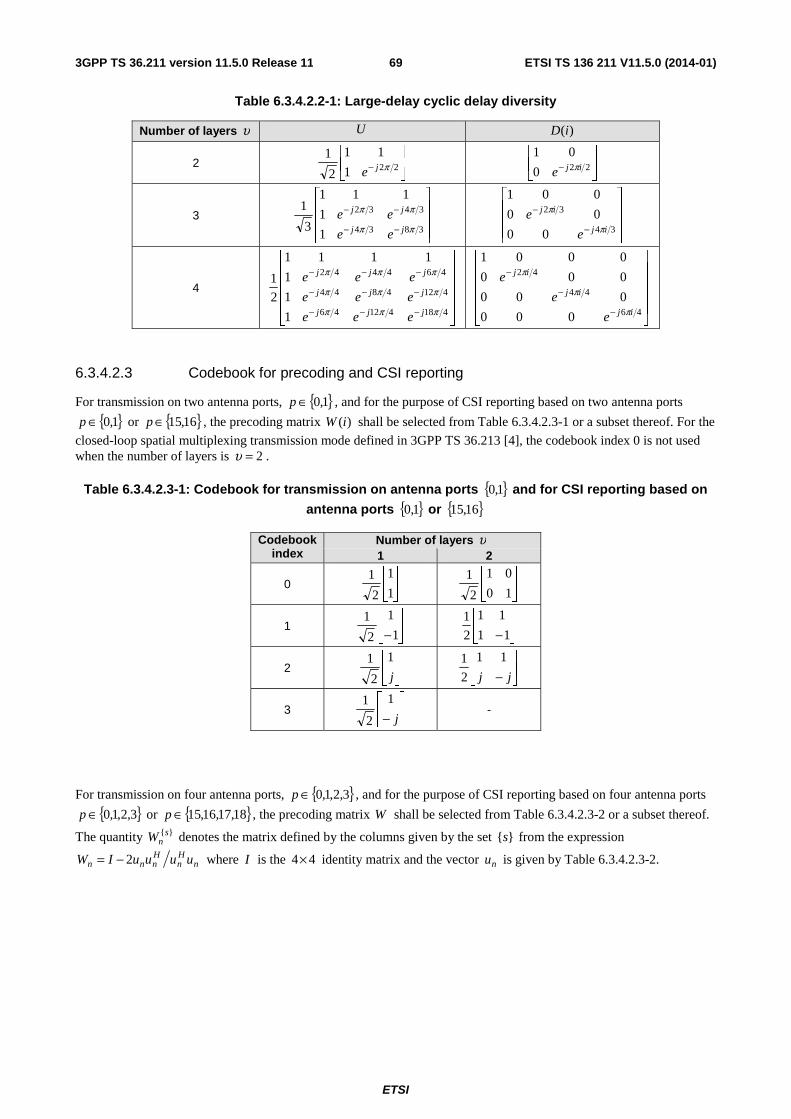
ETSI
ETSI TS 136 211 V11.5.0 (2014-01)693GPP TS 36.211 version 11.5.0 Release 11
Table 6.3.4.2.2-1: Large-delay cyclic delay diversity
Number of layers υ U )(iD
2 ⎥⎦
⎤⎢⎣
⎡− 221
11
2
1πje
⎥⎦
⎤⎢⎣
⎡− 220
01ije π
3
⎥⎥⎥
⎦
⎤
⎢⎢⎢
⎣
⎡
−−
−−
3834
3432
1
1
111
3
1
ππ
ππ
jj
jj
ee
ee
⎥⎥⎥
⎦
⎤
⎢⎢⎢
⎣
⎡
−
−
34
32
00
00
001
ij
ij
e
eπ
π
4
⎥⎥⎥⎥
⎦
⎤
⎢⎢⎢⎢
⎣
⎡
−−−
−−−
−−−
41841246
4124844
464442
1
1
1
1111
2
1
πππ
πππ
πππ
jjj
jjj
jjj
eee
eee
eee
⎥⎥⎥⎥
⎦
⎤
⎢⎢⎢⎢
⎣
⎡
−
−
−
46
44
42
000
000
000
0001
ij
ij
ij
e
e
e
π
π
π
6.3.4.2.3 Codebook for precoding and CSI reporting
For transmission on two antenna ports, { }1,0∈p , and for the purpose of CSI reporting based on two antenna ports
{ }1,0∈p or { }16,15∈p , the precoding matrix )(iW shall be selected from Table 6.3.4.2.3-1 or a subset thereof. For the
closed-loop spatial multiplexing transmission mode defined in 3GPP TS 36.213 [4], the codebook index 0 is not used when the number of layers is 2=υ .
Table 6.3.4.2.3-1: Codebook for transmission on antenna ports { }1,0 and for CSI reporting based on
antenna ports { }1,0 or { }16,15
Codebook index
Number of layers υ 1 2
0 ⎥⎦
⎤⎢⎣
⎡
1
1
2
1 ⎥
⎦
⎤⎢⎣
⎡
10
01
2
1
1 ⎥⎦
⎤⎢⎣
⎡
−1
1
2
1 ⎥
⎦
⎤⎢⎣
⎡
−11
11
2
1
2 ⎥⎦
⎤⎢⎣
⎡
j
1
2
1 ⎥
⎦
⎤⎢⎣
⎡
− jj
11
2
1
3 ⎥⎦
⎤⎢⎣
⎡
− j
1
2
1 -
For transmission on four antenna ports, { }3,2,1,0∈p , and for the purpose of CSI reporting based on four antenna ports
{ }3,2,1,0∈p or { }18,17,16,15∈p , the precoding matrix W shall be selected from Table 6.3.4.2.3-2 or a subset thereof.
The quantity }{snW denotes the matrix defined by the columns given by the set }{s from the expression
nHn
Hnnn uuuuIW 2−= where I is the 44× identity matrix and the vector nu is given by Table 6.3.4.2.3-2.

ETSI
ETSI TS 136 211 V11.5.0 (2014-01)703GPP TS 36.211 version 11.5.0 Release 11
Table 6.3.4.2.3-2: Codebook for transmission on antenna ports { }3,2,1,0 and for CSI reporting based on
antenna ports { }3,2,1,0 or { }18,17,16,15
Codebook index nu Number of layers υ 1 2 3 4
0 [ ]Tu 11110 −−−= }1{0W 2}14{
0W 3}124{0W 2}1234{
0W
1 [ ]Tjju 111 −= }1{1W 2}12{
1W 3}123{1W 2}1234{
1W
2 [ ]Tu 11112 −= }1{2W 2}12{
2W 3}123{2W 2}3214{
2W
3 [ ]Tjju −= 113 }1{3W 2}12{
3W 3}123{3W 2}3214{
3W
4 [ ]Tjjju 2)1(2)1(14 −−−−= }1{
4W 2}14{4W 3}124{
4W 2}1234{4W
5 [ ]Tjjju 2)1(2)1(15 −−−= }1{
5W 2}14{5W 3}124{
5W 2}1234{5W
6 [ ]Tjjju 2)1(2)1(16 +−−+= }1{
6W 2}13{6W 3}134{
6W 2}1324{6W
7 [ ]Tjjju 2)1(2)1(17 ++−= }1{
7W 2}13{7W 3}134{
7W 2}1324{7W
8 [ ]Tu 11118 −= }1{8W 2}12{
8W 3}124{8W 2}1234{
8W
9 [ ]Tjju −−−= 119 }1{9W 2}14{
9W 3}134{9W 2}1234{
9W
10 [ ]Tu 111110 −= }1{10W 2}13{
10W 3}123{10W 2}1324{
10W
11 [ ]Tjju 1111 −= }1{11W 2}13{
11W 3}134{11W 2}1324{
11W
12 [ ]Tu 111112 −−= }1{12W 2}12{
12W 3}123{12W 2}1234{
12W
13 [ ]Tu 111113 −−= }1{13W 2}13{
13W 3}123{13W 2}1324{
13W
14 [ ]Tu 111114 −−= }1{14W 2}13{
14W 3}123{14W 2}3214{
14W
15 [ ]Tu 111115 = }1{15W 2}12{
15W 3}123{15W 2}1234{
15W
For the purpose of CSI reporting for eight CSI reference signals the codebooks are given in clause 7.2.4 of 3GPP TS 36.213 [4].
6.3.4.3 Precoding for transmit diversity
Precoding for transmit diversity is only used in combination with layer mapping for transmit diversity as described in clause 6.3.3.3. The precoding operation for transmit diversity is defined for two and four antenna ports.
For transmission on two antenna ports, { }1,0∈p , the output [ ]Tiyiyiy )()()( )1()0(= , 1,...,1,0 apsymb −= Mi of the
precoding operation is defined by
( )( )( )( )⎥⎥
⎥⎥⎥
⎦
⎤
⎢⎢⎢⎢⎢
⎣
⎡
⎥⎥⎥⎥
⎦
⎤
⎢⎢⎢⎢
⎣
⎡
−
−=
⎥⎥⎥⎥⎥
⎦
⎤
⎢⎢⎢⎢⎢
⎣
⎡
++
)(Im
)(Im
)(Re
)(Re
001
010
010
001
2
1
)12(
)12(
)2(
)2(
)1(
)0(
)1(
)0(
)1(
)0(
)1(
)0(
ix
ix
ix
ix
j
j
j
j
iy
iy
iy
iy
for 1,...,1,0 layersymb −= Mi with layer
symbapsymb 2MM = .
For transmission on four antenna ports, { }3,2,1,0∈p , the output [ ]Tiyiyiyiyiy )()()()()( )3()2()1()0(= ,
1,...,1,0 apsymb −= Mi of the precoding operation is defined by
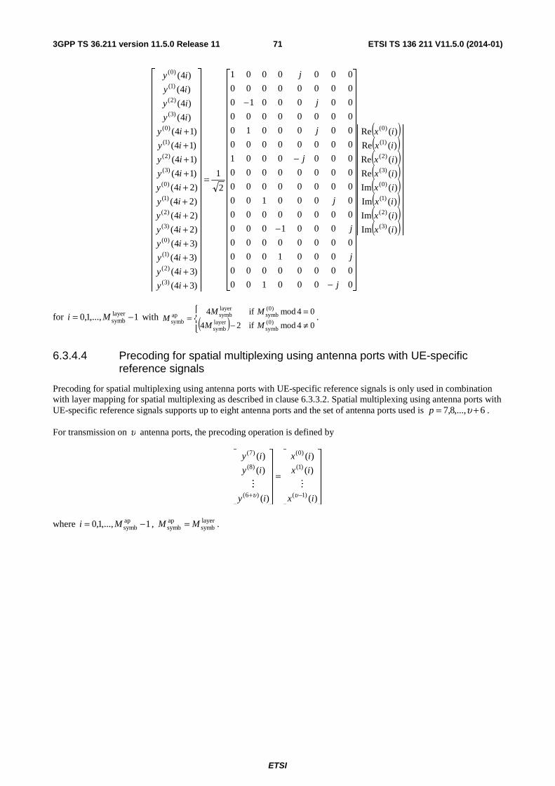
ETSI
ETSI TS 136 211 V11.5.0 (2014-01)713GPP TS 36.211 version 11.5.0 Release 11
( )( )( )( )( )( )( )( )⎥⎥
⎥⎥⎥⎥⎥⎥⎥⎥⎥
⎦
⎤
⎢⎢⎢⎢⎢⎢⎢⎢⎢⎢⎢
⎣
⎡
⎥⎥⎥⎥⎥⎥⎥⎥⎥⎥⎥⎥⎥⎥⎥⎥⎥⎥⎥⎥⎥⎥⎥
⎦
⎤
⎢⎢⎢⎢⎢⎢⎢⎢⎢⎢⎢⎢⎢⎢⎢⎢⎢⎢⎢⎢⎢⎢⎢
⎣
⎡
−
−
−
−
=
⎥⎥⎥⎥⎥⎥⎥⎥⎥⎥⎥⎥⎥⎥⎥⎥⎥⎥⎥⎥⎥⎥⎥⎥
⎦
⎤
⎢⎢⎢⎢⎢⎢⎢⎢⎢⎢⎢⎢⎢⎢⎢⎢⎢⎢⎢⎢⎢⎢⎢⎢
⎣
⎡
++++++++++++
)(Im
)(Im
)(Im
)(Im
)(Re
)(Re
)(Re
)(Re
0000100
00000000
0001000
00000000
0001000
00000000
0000100
00000000
00000000
0000001
00000000
0000010
00000000
0000010
00000000
0000001
2
1
)34(
)34(
)34(
)34(
)24(
)24(
)24(
)24(
)14(
)14(
)14(
)14(
)4(
)4(
)4(
)4(
)3(
)2(
)1(
)0(
)3(
)2(
)1(
)0(
)3(
)2(
)1(
)0(
)3(
)2(
)1(
)0(
)3(
)2(
)1(
)0(
)3(
)2(
)1(
)0(
ix
ix
ix
ix
ix
ix
ix
ix
j
j
j
j
j
j
j
j
iy
iy
iy
iy
iy
iy
iy
iy
iy
iy
iy
iy
iy
iy
iy
iy
for 1,...,1,0 layersymb −= Mi with ( )⎪⎩
⎪⎨⎧
≠−=
=04mod if24
04mod if4)0(
symblayersymb
)0(symb
layersymbap
symb MM
MMM .
6.3.4.4 Precoding for spatial multiplexing using antenna ports with UE-specific reference signals
Precoding for spatial multiplexing using antenna ports with UE-specific reference signals is only used in combination with layer mapping for spatial multiplexing as described in clause 6.3.3.2. Spatial multiplexing using antenna ports with UE-specific reference signals supports up to eight antenna ports and the set of antenna ports used is 6,...,8,7 += υp .
For transmission on υ antenna ports, the precoding operation is defined by
⎥⎥⎥⎥⎥
⎦
⎤
⎢⎢⎢⎢⎢
⎣
⎡
=
⎥⎥⎥⎥⎥
⎦
⎤
⎢⎢⎢⎢⎢
⎣
⎡
−+ )(
)(
)(
)(
)(
)(
)1(
)1(
)0(
)6(
)8(
)7(
ix
ix
ix
iy
iy
iy
υυMM
where 1,...,1,0 apsymb −= Mi , layer
symbapsymb MM = .
ETSI
ETSI TS 136 211 V11.5.0 (2014-01)723GPP TS 36.211 version 11.5.0 Release 11
6.3.5 Mapping to resource elements
For each of the antenna ports used for transmission of the physical channel, the block of complex-valued symbols
)1(),...,0( apsymb
)()( −Myy pp shall conform to the downlink power allocation specified in clause 5.2 in
3GPP TS 36.213 [4] and be mapped in sequence starting with )0()( py to resource elements ( )lk, which meet all of the
following criteria in the current subframe:
- they are in the physical resource blocks corresponding to the virtual resource blocks assigned for transmission, and
- they are not used for transmission of PBCH, synchronization signals, and
- they are assumed by the UE not to be used for cell-specific reference signals, where the positions of the cell-specific reference signals are given by clause 6.10.1.2 with the number of antenna ports for and the frequency shift of cell-specific reference signals derived as described in clause 6.10.1.2 4, and
The mapping to resource elements ( )lk, on antenna port p not reserved for other purposes shall be in increasing order
of first the index k over the assigned physical resource blocks and then the index l , starting with the first slot in a subframe.
ETSI
ETSI TS 136 211 V11.5.0 (2014-01)733GPP TS 36.211 version 11.5.0 Release 11
6.4 Physical downlink shared channel The physical downlink shared channel shall be processed and mapped to resource elements as described in clause 6.3 with the following additions and exceptions:
- In resource blocks in which UE-specific reference signals are not transmitted, the PDSCH shall be transmitted on the same set of antenna ports as the PBCH, which is one of { }0 , { }1,0 , or { }3,2,1,0 .
- In resource blocks in which UE-specific reference signals are transmitted, the PDSCH shall be transmitted on antenna port(s) { }5 , { }7 , { }8 , or { }6,...,8,7 +∈ υp , where υ is the number of layers used for transmission of the
PDSCH.
- If PDSCH is transmitted in MBSFN subframes as defined in 3GPP TS 36.213 [4], the PDSCH shall be transmitted on one or several of antenna port(s) { }6,...,8,7 +∈ υp , where υ is the number of layers used for
transmission of the PDSCH.
- PDSCH is not mapped to resource elements used for UE-specific reference signals associated with PDSCH
- In mapping to resource elements, the positions of the cell-specific reference signals are given by clause 6.10.1.2 with the number of antenna ports and the frequency shift of the cell-specific reference signals derived as described in clause 6.10.1.2, unless other values for these parameters are provided by clause 7.1.9 in 3GPP TS 36.213 [4], in which case these values are used in the resource blocks indicated by the relevant DCI.
- If the DCI associated with the PDSCH uses the C-RNTI or semi-persistent C-RNTI, the PDSCH is not mapped to resource elements assumed by the UE to be used for transmission of CSI reference signals, where the positions of the CSI reference signals are given by clause 6.10.5.2.The configuration for zero power CSI reference signals is obtained as described in clause 6.10.5.2, unless other values for these parameters are provided by clause 7.1.9 in 3GPP TS 36.213 [4], in which case these values are used in the resource blocks indicated by the relevant DCI. The configuration for non-zero power CSI reference signals is obtained as described in clause 6.10.5.2,
- PDSCH is not mapped to any physical resource-block pair(s) carrying an EPDCCH associated with the PDSCH.
- The index l in the first slot in a subframe fulfils DataStartll ≥ where DataStartl is given by clause 7.1.6.4 of
3GPP TS 36.213 [4].
- In mapping to resource elements, if the DCI associated with the PDSCH uses the C-RNTI or semi-persistent C-RNTI and transmit diversity according to clause 6.3.4.3 is used, resource elements in an OFDM symbol assumed by the UE to contain CSI-RS shall be used in the mapping if and only if all of the following criteria are fulfilled:
- there is an even number of resource elements for the OFDM symbol in each resource block assigned for transmission, and
- the complex-valued symbols )()( iy p and )1()( +iy p , where i is an even number, can be mapped to resource
elements ( )lk, and ( )lnk ,+ in the same OFDM symbol with 3<n .
6.5 Physical multicast channel The physical multicast channel shall be processed and mapped to resource elements as described in clause 6.3 with the following exceptions:
- No transmit diversity scheme is specified.
- Layer mapping and precoding shall be done assuming a single antenna port and the transmission shall use antenna port 4.
- The PMCH can only be transmitted in the MBSFN region of an MBSFN subframe.
- The PMCH shall use extended cyclic prefix.
- The PMCH is not mapped to resource elements used for transmission of MBSFN reference signals.

ETSI
ETSI TS 136 211 V11.5.0 (2014-01)743GPP TS 36.211 version 11.5.0 Release 11
6.6 Physical broadcast channel
6.6.1 Scrambling
The block of bits )1(),...,0( bit −Mbb , where bitM , the number of bits transmitted on the physical broadcast channel,
equals 1920 for normal cyclic prefix and 1728 for extended cyclic prefix, shall be scrambled with a cell-specific
sequence prior to modulation, resulting in a block of scrambled bits )1(~
),...,0(~
bit −Mbb according to
( ) 2mod)()()(~
icibib +=
where the scrambling sequence )(ic is given by clause 7.2. The scrambling sequence shall be initialised with cellIDinit Nc = in each radio frame fulfilling 04modf =n .
6.6.2 Modulation
The block of scrambled bits )1(~
),...,0(~
bit −Mbb shall be modulated as described in clause 7.1, resulting in a block of
complex-valued modulation symbols )1(),...,0( symb −Mdd . Table 6.6.2-1 specifies the modulation mappings applicable
for the physical broadcast channel.
Table 6.6.2-1: PBCH modulation schemes.
Physical channel Modulation schemes PBCH QPSK
6.6.3 Layer mapping and precoding
The block of modulation symbols )1(),...,0( symb −Mdd shall be mapped to layers according to one of clauses 6.3.3.1 or
6.3.3.3 with symb)0(
symb MM = and precoded according to one of clauses 6.3.4.1 or 6.3.4.3, resulting in a block of vectors
[ ]TP iyiyiy )(...)()( )1()0( −= , 1,...,0 symb −= Mi , where )()( iy p represents the signal for antenna port p and where
1,...,0 −= Pp and the number of antenna ports for cell-specific reference signals { }4,2,1∈P .
6.6.4 Mapping to resource elements
The block of complex-valued symbols )1(),...,0( symb)()( −Myy pp for each antenna port is transmitted during 4
consecutive radio frames starting in each radio frame fulfilling 04modf =n and shall be mapped in sequence starting
with )0(y to resource elements ( )lk, . The mapping to resource elements ( )lk, not reserved for transmission of
reference signals shall be in increasing order of first the index k , then the index l in slot 1 in subframe 0 and finally the radio frame number. The resource-element indices are given by
3,...,1,0
71,...,1,0' ,'362
RBsc
DLRB
=
=+−=
l
kkNN
k
where resource elements reserved for reference signals shall be excluded. The mapping operation shall assume cell-specific reference signals for antenna ports 0-3 being present irrespective of the actual configuration. The UE shall assume that the resource elements assumed to be reserved for reference signals in the mapping operation above but not used for transmission of reference signal are not available for PDSCH transmission. The UE shall not make any other assumptions about these resource elements.
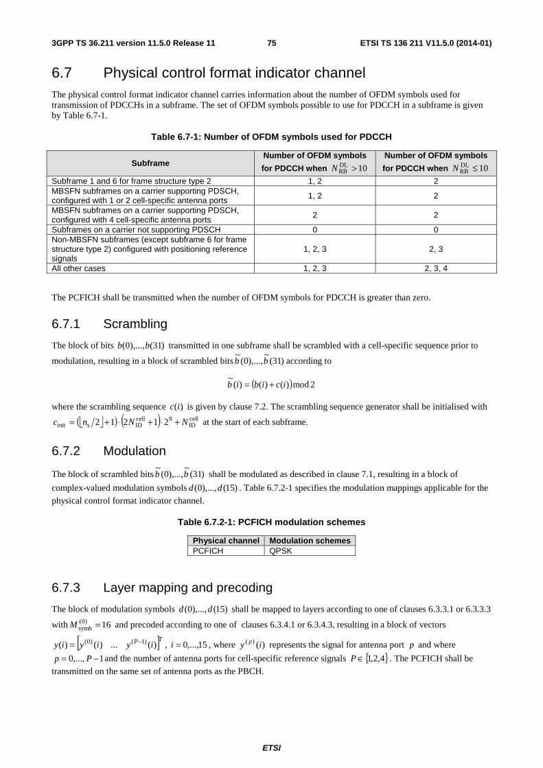
ETSI
ETSI TS 136 211 V11.5.0 (2014-01)753GPP TS 36.211 version 11.5.0 Release 11
6.7 Physical control format indicator channel The physical control format indicator channel carries information about the number of OFDM symbols used for transmission of PDCCHs in a subframe. The set of OFDM symbols possible to use for PDCCH in a subframe is given by Table 6.7-1.
Table 6.7-1: Number of OFDM symbols used for PDCCH
Subframe Number of OFDM symbols
for PDCCH when 10DLRB >N
Number of OFDM symbols
for PDCCH when 10DLRB ≤N
Subframe 1 and 6 for frame structure type 2 1, 2 2 MBSFN subframes on a carrier supporting PDSCH, configured with 1 or 2 cell-specific antenna ports 1, 2 2
MBSFN subframes on a carrier supporting PDSCH, configured with 4 cell-specific antenna ports
2 2
Subframes on a carrier not supporting PDSCH 0 0 Non-MBSFN subframes (except subframe 6 for frame structure type 2) configured with positioning reference signals
1, 2, 3 2, 3
All other cases 1, 2, 3 2, 3, 4
The PCFICH shall be transmitted when the number of OFDM symbols for PDCCH is greater than zero.
6.7.1 Scrambling
The block of bits )31(),...,0( bb transmitted in one subframe shall be scrambled with a cell-specific sequence prior to
modulation, resulting in a block of scrambled bits )31(~
),...,0(~
bb according to
( ) 2mod)()()(~
icibib +=
where the scrambling sequence )(ic is given by clause 7.2. The scrambling sequence generator shall be initialised with
⎣ ⎦( ) ( ) cellID
9cellIDsinit 21212 NNnc +⋅+⋅+= at the start of each subframe.
6.7.2 Modulation
The block of scrambled bits )31(~
),...,0(~
bb shall be modulated as described in clause 7.1, resulting in a block of
complex-valued modulation symbols )15(),...,0( dd . Table 6.7.2-1 specifies the modulation mappings applicable for the
physical control format indicator channel.
Table 6.7.2-1: PCFICH modulation schemes
Physical channel Modulation schemes PCFICH QPSK
6.7.3 Layer mapping and precoding
The block of modulation symbols )15(),...,0( dd shall be mapped to layers according to one of clauses 6.3.3.1 or 6.3.3.3
with 16)0(symb =M and precoded according to one of clauses 6.3.4.1 or 6.3.4.3, resulting in a block of vectors
[ ]TP iyiyiy )(...)()( )1()0( −= , 15,...,0=i , where )()( iy p represents the signal for antenna port p and where
1,...,0 −= Pp and the number of antenna ports for cell-specific reference signals { }4,2,1∈P . The PCFICH shall be
transmitted on the same set of antenna ports as the PBCH.
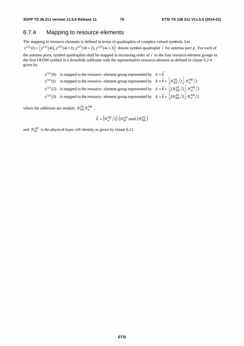
ETSI
ETSI TS 136 211 V11.5.0 (2014-01)763GPP TS 36.211 version 11.5.0 Release 11
6.7.4 Mapping to resource elements
The mapping to resource elements is defined in terms of quadruplets of complex-valued symbols. Let
)34(),24(),14(),4()( )()()()()( +++= iyiyiyiyiz ppppp denote symbol quadruplet i for antenna port p . For each of
the antenna ports, symbol quadruplets shall be mapped in increasing order of i to the four resource-element groups in the first OFDM symbol in a downlink subframe with the representative resource-element as defined in clause 6.2.4 given by
⎣ ⎦⎣ ⎦⎣ ⎦ 223by drepresente groupelement -resource the tomapped is)3(
222by drepresente groupelement -resource the tomapped is)2(
22by drepresente groupelement -resource the tomapped is)1(
by drepresente groupelement -resource the tomapped is)0(
RBsc
DLRB
)(
RBsc
DLRB
)(
RBsc
DLRB
)(
)(
NNkkz
NNkkz
NNkkz
kkz
p
p
p
p
⋅+=
⋅+=
⋅+==
where the additions are modulo RBsc
DLRB NN ,
( ) ( )DLRB
cellID
RBsc 2mod2 NNNk ⋅=
and cellIDN is the physical-layer cell identity as given by clause 6.11.
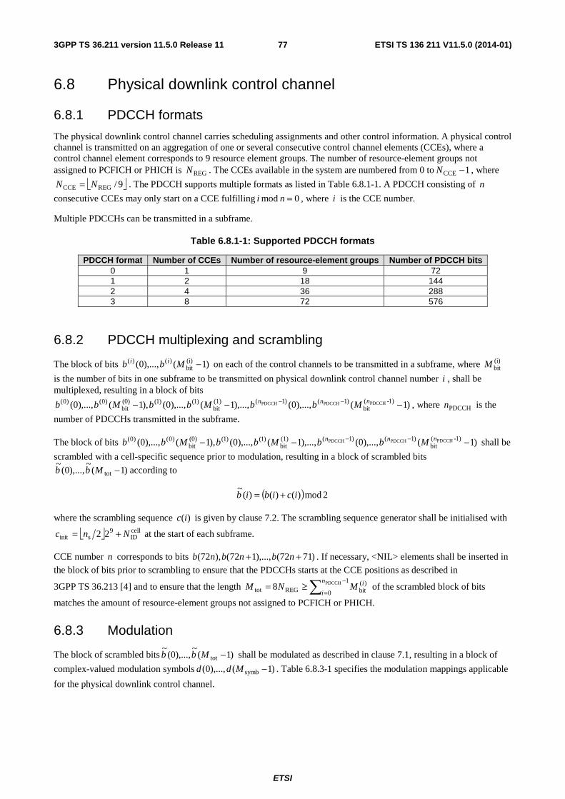
ETSI
ETSI TS 136 211 V11.5.0 (2014-01)773GPP TS 36.211 version 11.5.0 Release 11
6.8 Physical downlink control channel
6.8.1 PDCCH formats
The physical downlink control channel carries scheduling assignments and other control information. A physical control channel is transmitted on an aggregation of one or several consecutive control channel elements (CCEs), where a control channel element corresponds to 9 resource element groups. The number of resource-element groups not assigned to PCFICH or PHICH is REGN . The CCEs available in the system are numbered from 0 to 1CCE −N , where
⎣ ⎦9/REGCCE NN = . The PDCCH supports multiple formats as listed in Table 6.8.1-1. A PDCCH consisting of n
consecutive CCEs may only start on a CCE fulfilling 0mod =ni , where i is the CCE number.
Multiple PDCCHs can be transmitted in a subframe.
Table 6.8.1-1: Supported PDCCH formats
PDCCH format Number of CCEs Number of resource-element groups Number of PDCCH bits 0 1 9 72 1 2 18 144 2 4 36 288 3 8 72 576
6.8.2 PDCCH multiplexing and scrambling
The block of bits )1(),...,0( (i)bit
)()( −Mbb ii on each of the control channels to be transmitted in a subframe, where (i)bitM
is the number of bits in one subframe to be transmitted on physical downlink control channel number i , shall be multiplexed, resulting in a block of bits
)1(),...,0(),...,1(),...,0(),1(),...,0( 1)-(bit
)1()1((1)bit
)1()1((0)bit
)0()0( PDCCHPDCCHPDCCH −−− −− nnn MbbMbbMbb , where PDCCHn is the
number of PDCCHs transmitted in the subframe.
The block of bits )1(),...,0(),...,1(),...,0(),1(),...,0( 1)-(bit
)1()1((1)bit
)1()1((0)bit
)0()0( PDCCHPDCCHPDCCH −−− −− nnn MbbMbbMbb shall be
scrambled with a cell-specific sequence prior to modulation, resulting in a block of scrambled bits
)1(~
),...,0(~
tot −Mbb according to
( ) 2mod)()()(~
icibib +=
where the scrambling sequence )(ic is given by clause 7.2. The scrambling sequence generator shall be initialised with
⎣ ⎦ cellID
9sinit 22 Nnc += at the start of each subframe.
CCE number n corresponds to bits )7172(),...,172(),72( ++ nbnbnb . If necessary, <NIL> elements shall be inserted in
the block of bits prior to scrambling to ensure that the PDCCHs starts at the CCE positions as described in
3GPP TS 36.213 [4] and to ensure that the length ∑−
=≥=
1
0
)(bitREGtot
PDCCH8n
i
iMNM of the scrambled block of bits
matches the amount of resource-element groups not assigned to PCFICH or PHICH.
6.8.3 Modulation
The block of scrambled bits )1(~
),...,0(~
tot −Mbb shall be modulated as described in clause 7.1, resulting in a block of
complex-valued modulation symbols )1(),...,0( symb −Mdd . Table 6.8.3-1 specifies the modulation mappings applicable
for the physical downlink control channel.
ETSI
ETSI TS 136 211 V11.5.0 (2014-01)783GPP TS 36.211 version 11.5.0 Release 11
Table 6.8.3-1: PDCCH modulation schemes
Physical channel Modulation schemes PDCCH QPSK
6.8.4 Layer mapping and precoding
The block of modulation symbols )1(),...,0( symb −Mdd shall be mapped to layers according to one of clauses 6.3.3.1 or
6.3.3.3 with symb)0(
symb MM = and precoded according to one of clauses 6.3.4.1 or 6.3.4.3, resulting in a block of vectors
[ ]TP iyiyiy )(...)()( )1()0( −= , 1,...,0 symb −= Mi to be mapped onto resources on the antenna ports used for
transmission, where )()( iy p represents the signal for antenna port p . The PDCCH shall be transmitted on the same set
of antenna ports as the PBCH.
6.8.5 Mapping to resource elements
The mapping to resource elements is defined by operations on quadruplets of complex-valued symbols. Let
)34(),24(),14(),4()( )()()()()( +++= iyiyiyiyiz ppppp denote symbol quadruplet i for antenna port p .
The block of quadruplets )1(),...,0( quad)()( −Mzz pp , where 4symbquad MM = , shall be permuted resulting in
)1(),...,0( quad)()( −Mww pp . The permutation shall be according to the sub-block interleaver in clause 5.1.4.2.1 of
3GPP TS 36.212 [3] with the following exceptions:
- the input and output to the interleaver is defined by symbol quadruplets instead of bits
- interleaving is performed on symbol quadruplets instead of bits by substituting the terms "bit", "bits" and "bit sequence" in clause 5.1.4.2.1 of 3GPP TS 36.212 [3] by "symbol quadruplet", "symbol quadruplets" and "symbol-quadruplet sequence", respectively
<NULL> elements at the output of the interleaver in 3GPP TS 36.212 [3] shall be removed when forming
)1(),...,0( quad)()( −Mww pp . Note that the removal of <NULL> elements does not affect any <NIL> elements inserted
in clause 6.8.2.
The block of quadruplets )1(),...,0( quad)()( −Mww pp shall be cyclically shifted, resulting in
)1(),...,0( quad)()( −Mww pp where ( ) ( )quad
cellID
)()( mod)( MNiwiw pp += .
Mapping of the block of quadruplets )1(),...,0( quad)()( −Mww pp is defined in terms of resource-element groups,
specified in clause 6.2.4, according to steps 1–10 below:
1) Initialize 0=′m (resource-element group number)
2) Initialize 0'=k
3) Initialize 0'=l
4) If the resource element ),( lk ′′ represents a resource-element group and the resource-element group is not
assigned to PCFICH or PHICH then perform step 5 and 6, else go to step 7
5) Map symbol-quadruplet )'()( mw p to the resource-element group represented by ),( lk ′′ for each
antenna port p
6) Increase m′ by 1
7) Increase 'l by 1
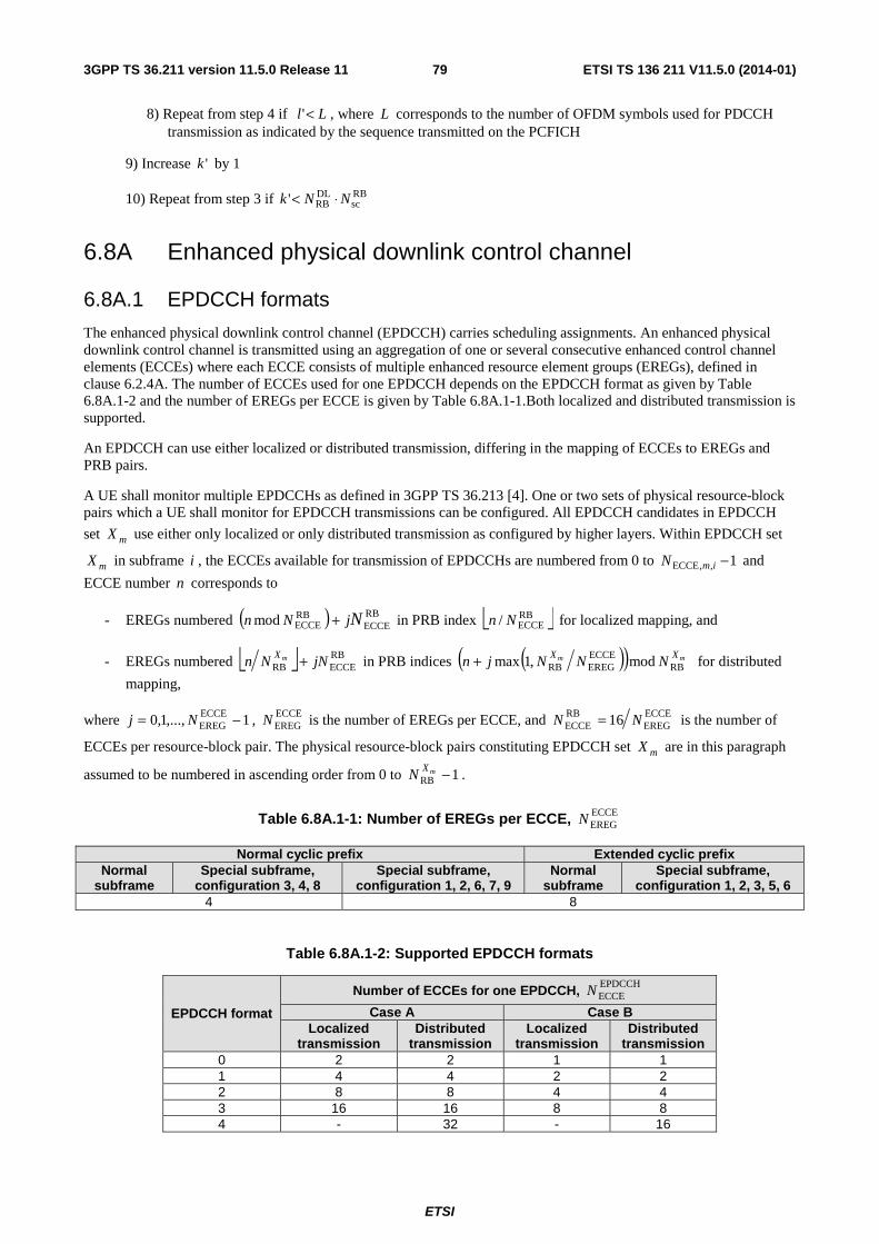
ETSI
ETSI TS 136 211 V11.5.0 (2014-01)793GPP TS 36.211 version 11.5.0 Release 11
8) Repeat from step 4 if Ll <' , where L corresponds to the number of OFDM symbols used for PDCCH transmission as indicated by the sequence transmitted on the PCFICH
9) Increase 'k by 1
10) Repeat from step 3 if RBsc
DLRB' NNk ⋅<
6.8A Enhanced physical downlink control channel
6.8A.1 EPDCCH formats
The enhanced physical downlink control channel (EPDCCH) carries scheduling assignments. An enhanced physical downlink control channel is transmitted using an aggregation of one or several consecutive enhanced control channel elements (ECCEs) where each ECCE consists of multiple enhanced resource element groups (EREGs), defined in clause 6.2.4A. The number of ECCEs used for one EPDCCH depends on the EPDCCH format as given by Table 6.8A.1-2 and the number of EREGs per ECCE is given by Table 6.8A.1-1.Both localized and distributed transmission is supported.
An EPDCCH can use either localized or distributed transmission, differing in the mapping of ECCEs to EREGs and PRB pairs.
A UE shall monitor multiple EPDCCHs as defined in 3GPP TS 36.213 [4]. One or two sets of physical resource-block pairs which a UE shall monitor for EPDCCH transmissions can be configured. All EPDCCH candidates in EPDCCH
set mX use either only localized or only distributed transmission as configured by higher layers. Within EPDCCH set
mX in subframe i , the ECCEs available for transmission of EPDCCHs are numbered from 0 to 1,,ECCE −imN and
ECCE number n corresponds to
- EREGs numbered ( ) RBECCE
RBECCEmod NjNn + in PRB index ⎣ ⎦RB
ECCE/ Nn for localized mapping, and
- EREGs numbered ⎣ ⎦ RBECCERB jNNn mX + in PRB indices ( )( ) mm XX
NNNjn RBECCEEREGRB mod,1max+ for distributed
mapping,
where 1,...,1,0 ECCEEREG −= Nj , ECCE
EREGN is the number of EREGs per ECCE, and ECCEEREG
RBECCE 16 NN = is the number of
ECCEs per resource-block pair. The physical resource-block pairs constituting EPDCCH set mX are in this paragraph
assumed to be numbered in ascending order from 0 to 1RB −mXN .
Table 6.8A.1-1: Number of EREGs per ECCE, ECCEEREGN
Normal cyclic prefix Extended cyclic prefix Normal
subframe Special subframe,
configuration 3, 4, 8 Special subframe,
configuration 1, 2, 6, 7, 9 Normal
subframe Special subframe,
configuration 1, 2, 3, 5, 6 4 8
Table 6.8A.1-2: Supported EPDCCH formats
EPDCCH format
Number of ECCEs for one EPDCCH, EPDCCHECCEN
Case A Case B Localized
transmission Distributed
transmission Localized
transmission Distributed
transmission 0 2 2 1 1 1 4 4 2 2 2 8 8 4 4 3 16 16 8 8 4 - 32 - 16
ETSI
ETSI TS 136 211 V11.5.0 (2014-01)803GPP TS 36.211 version 11.5.0 Release 11
Case A in Table 6.8A.1-2 is used when the conditions corresponding to case 1 in clause 9.1.4 of 3GPP TS 36.213 [4] are satisfied, otherwise case B is used. The quantity EPDCCHn for a particular UE and referenced in 3GPP TS 36.213 [4]
is defined as the number of downlink resource elements ),( lk in a physical resource-block pair configured for possible
EPDCCH transmission of EPDCCH set 0X and fulfilling all of the following criteria:
- they are part of any one of the 16 EREGs in the physical resource-block pair, and
- they are assumed by the UE not to be used for cell-specific reference signals, where the positions of the cell-specific reference signals are given by clause 6.10.1.2 with the number of antenna ports for and the frequency shift of cell-specific reference signals derived as described in clause 6.10.1.2 unless other values for these parameters are provided by clause 9.1.4.3 in 3GPP TS 36.213 [4], and-
- they are assumed by the UE not to be used for transmission of CSI reference signals, where the positions of the CSI reference signals are given by clause 6.10.5.2 with the configuration for zero power CSI reference signals obtained as described in clause 6.10.5.2 unless other values are provided by clause 9.1.4.3 in 3GPP TS 36.213 [4], and with the configuration for non-zero power CSI reference signals obtained as described in clause 6.10.5.2, and
- the index l in the first slot in a subframe fulfils tEPDCCHStarll ≥ where tEPDCCHStarl is given by clause 9.1.4.1 of
3GPP TS 36.213 [4].
6.8A.2 Scrambling
The block of bits )1(),...,0( bit −Mbb to be transmitted on an EPDCCH in a subframe shall be scrambled, resulting in a
block of scrambled bits )1(~
),...,0(~
bit −Mbb according to
( ) 2mod)()()(~
icibib +=
where the UE-specific scrambling sequence )(ic is given by clause 7.2. The scrambling sequence generator shall be
initialized with ⎣ ⎦ EPDCCH,ID
9sinit 22 mnnc +⋅= where m is the EPDCCH set number.
6.8A.3 Modulation
The block of scrambled bits )1(~
),...,0(~
bit −Mbb shall be modulated as described in clause 7.1, resulting in a block of
complex-valued modulation symbols )1(),...,0( symb −Mdd . Table 6.8A.3-1 specifies the modulation mappings
applicable for the enhanced physical downlink control channel.
Table 6.8A.3-1: EPDCCH modulation schemes
Physical channel Modulation schemes EPDCCH QPSK
6.8A.4 Layer mapping and precoding
The block of complex-valued modulation symbols shall be mapped to a single layer and precoded according to )()( idiy = , 1,...,0 symb −= Mi .
6.8A.5 Mapping to resource elements
The block of complex-valued symbols )1(),...,0( symb −Myy shall be mapped in sequence starting with )0(y to
resource elements ( )lk, on the associated antenna port which meet all of the following criteria:
- they are part of the EREGs assigned for the EPDCCH transmission, and
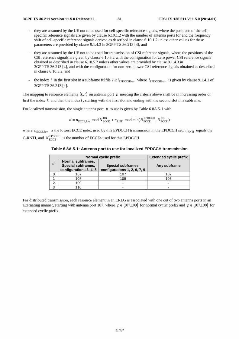
ETSI
ETSI TS 136 211 V11.5.0 (2014-01)813GPP TS 36.211 version 11.5.0 Release 11
- they are assumed by the UE not to be used for cell-specific reference signals, where the positions of the cell-specific reference signals are given by clause 6.10.1.2 with the number of antenna ports for and the frequency shift of cell-specific reference signals derived as described in clause 6.10.1.2 unless other values for these parameters are provided by clause 9.1.4.3 in 3GPP TS 36.213 [4], and
- they are assumed by the UE not to be used for transmission of CSI reference signals, where the positions of the CSI reference signals are given by clause 6.10.5.2 with the configuration for zero power CSI reference signals obtained as described in clause 6.10.5.2 unless other values are provided by clause 9.1.4.3 in 3GPP TS 36.213 [4], and with the configuration for non-zero power CSI reference signals obtained as described in clause 6.10.5.2, and
- the index l in the first slot in a subframe fulfils tEPDCCHStarll ≥ where tEPDCCHStarl is given by clause 9.1.4.1 of
3GPP TS 36.213 [4].
The mapping to resource elements ( )lk, on antenna port p meeting the criteria above shall be in increasing order of
first the index k and then the index l , starting with the first slot and ending with the second slot in a subframe.
For localized transmission, the single antenna port p to use is given by Table 6.8A.5-1 with
),min(modmod' RBECCE
EPDCCHECCERNTI
RBECCElowECCE, NNnNnn +=
where lowECCE,n is the lowest ECCE index used by this EPDCCH transmission in the EPDCCH set, RNTIn equals the
C-RNTI, and EPDCCHECCEN is the number of ECCEs used for this EPDCCH.
Table 6.8A.5-1: Antenna port to use for localized EPDCCH transmission
'n
Normal cyclic prefix Extended cyclic prefix Normal subframes, Special subframes,
configurations 3, 4, 8
Special subframes,
configurations 1, 2, 6, 7, 9 Any subframe
0 107 107 107 1 108 109 108 2 109 - - 3 110 - -
For distributed transmission, each resource element in an EREG is associated with one out of two antenna ports in an alternating manner, starting with antenna port 107, where { }109,107∈p for normal cyclic prefix and { }108,107∈p for
extended cyclic prefix.
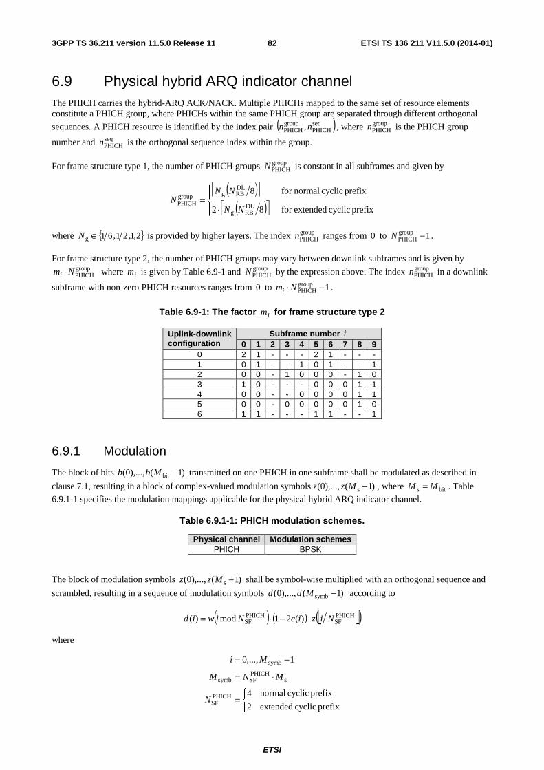
ETSI
ETSI TS 136 211 V11.5.0 (2014-01)823GPP TS 36.211 version 11.5.0 Release 11
6.9 Physical hybrid ARQ indicator channel The PHICH carries the hybrid-ARQ ACK/NACK. Multiple PHICHs mapped to the same set of resource elements constitute a PHICH group, where PHICHs within the same PHICH group are separated through different orthogonal
sequences. A PHICH resource is identified by the index pair ( )seqPHICH
groupPHICH , nn , where group
PHICHn is the PHICH group
number and seqPHICHn is the orthogonal sequence index within the group.
For frame structure type 1, the number of PHICH groups groupPHICHN is constant in all subframes and given by
( )⎡ ⎤( )⎡ ⎤⎪⎩
⎪⎨
⎧
⋅=
prefix cyclic extendedfor 82
prefix cyclic normalfor 8
DLRBg
DLRBggroup
PHICHNN
NNN
where { }2,1,21,61g ∈N is provided by higher layers. The index groupPHICHn ranges from 0 to 1group
PHICH −N .
For frame structure type 2, the number of PHICH groups may vary between downlink subframes and is given by groupPHICHNmi ⋅ where im is given by Table 6.9-1 and group
PHICHN by the expression above. The index groupPHICHn in a downlink
subframe with non-zero PHICH resources ranges from 0 to 1groupPHICH −⋅ Nmi .
Table 6.9-1: The factor im for frame structure type 2
Uplink-downlink configuration
Subframe number i 0 1 2 3 4 5 6 7 8 9
0 2 1 - - - 2 1 - - - 1 0 1 - - 1 0 1 - - 1 2 0 0 - 1 0 0 0 - 1 0 3 1 0 - - - 0 0 0 1 1 4 0 0 - - 0 0 0 0 1 1 5 0 0 - 0 0 0 0 0 1 0 6 1 1 - - - 1 1 - - 1
6.9.1 Modulation
The block of bits )1(),...,0( bit −Mbb transmitted on one PHICH in one subframe shall be modulated as described in
clause 7.1, resulting in a block of complex-valued modulation symbols )1(),...,0( s −Mzz , where bits MM = . Table
6.9.1-1 specifies the modulation mappings applicable for the physical hybrid ARQ indicator channel.
Table 6.9.1-1: PHICH modulation schemes.
Physical channel Modulation schemes PHICH BPSK
The block of modulation symbols )1(),...,0( s −Mzz shall be symbol-wise multiplied with an orthogonal sequence and
scrambled, resulting in a sequence of modulation symbols )1(),...,0( symb −Mdd according to
( ) ( ) ⎣ ⎦( )PHICHSF
PHICHSF )(21mod)( NizicNiwid ⋅−⋅=
where
⎩⎨⎧
=
⋅=
−=
prefix cyclic extended2
prefix cyclic normal4
1,...,0
PHICHSF
sPHICHSFsymb
symb
N
MNM
Mi
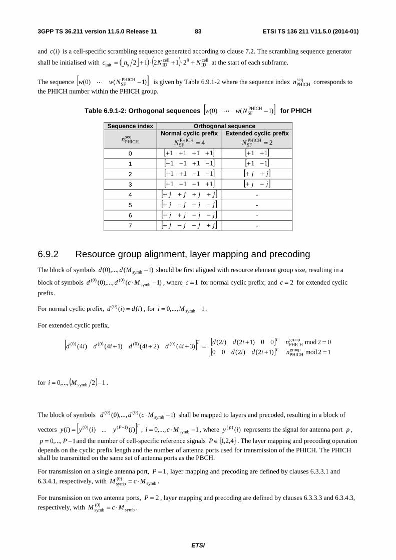
ETSI
ETSI TS 136 211 V11.5.0 (2014-01)833GPP TS 36.211 version 11.5.0 Release 11
and )(ic is a cell-specific scrambling sequence generated according to clause 7.2. The scrambling sequence generator
shall be initialised with ⎣ ⎦( ) ( ) cellID
9cellIDsinit 21212 NNnc +⋅+⋅+= at the start of each subframe.
The sequence [ ])1()0( PHICHSF −Nww L is given by Table 6.9.1-2 where the sequence index seq
PHICHn corresponds to
the PHICH number within the PHICH group.
Table 6.9.1-2: Orthogonal sequences [ ])1()0( PHICHSF −Nww L for PHICH
Sequence index Orthogonal sequence
seqPHICHn
Normal cyclic prefix
4PHICHSF =N
Extended cyclic prefix
2PHICHSF =N
0 [ ]1111 ++++ [ ]11 ++
1 [ ]1111 −+−+ [ ]11 −+
2 [ ]1111 −−++ [ ]jj ++
3 [ ]1111 +−−+ [ ]jj −+
4 [ ]jjjj ++++ -
5 [ ]jjjj −+−+ -
6 [ ]jjjj −−++ -
7 [ ]jjjj +−−+ -
6.9.2 Resource group alignment, layer mapping and precoding
The block of symbols )1(),...,0( symb −Mdd should be first aligned with resource element group size, resulting in a
block of symbols )1(),...,0( symb)0()0( −⋅ Mcdd , where 1=c for normal cyclic prefix; and 2=c for extended cyclic
prefix.
For normal cyclic prefix, )()()0( idid = , for 1,...,0 symb −= Mi .
For extended cyclic prefix,
[ ] [ ][ ]⎪⎩
⎪⎨⎧
=+=+=+++
12mod)12()2(00
02mod00)12()2()34()24()14()4(
groupPHICH
groupPHICH)0()0()0()0(
nidid
nidididididid T
TT
for ( ) 12,...,0 symb −= Mi .
The block of symbols )1(),...,0( symb)0()0( −⋅ Mcdd shall be mapped to layers and precoded, resulting in a block of
vectors [ ]TP iyiyiy )(...)()( )1()0( −= , 1,...,0 symb −⋅= Mci , where )()( iy p represents the signal for antenna port p ,
1,...,0 −= Pp and the number of cell-specific reference signals { }4,2,1∈P . The layer mapping and precoding operation
depends on the cyclic prefix length and the number of antenna ports used for transmission of the PHICH. The PHICH shall be transmitted on the same set of antenna ports as the PBCH.
For transmission on a single antenna port, 1=P , layer mapping and precoding are defined by clauses 6.3.3.1 and
6.3.4.1, respectively, with symb(0)symb McM ⋅= .
For transmission on two antenna ports, 2=P , layer mapping and precoding are defined by clauses 6.3.3.3 and 6.3.4.3,
respectively, with symb(0)symb McM ⋅= .
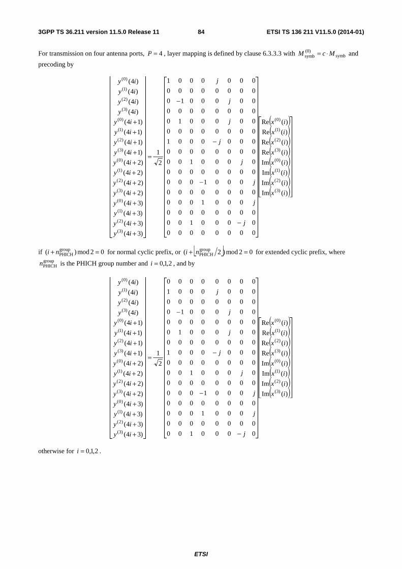
ETSI
ETSI TS 136 211 V11.5.0 (2014-01)843GPP TS 36.211 version 11.5.0 Release 11
For transmission on four antenna ports, 4=P , layer mapping is defined by clause 6.3.3.3 with symb(0)symb McM ⋅= and
precoding by
( )( )( )( )( )( )( )( )⎥⎥
⎥⎥⎥⎥⎥⎥⎥⎥⎥
⎦
⎤
⎢⎢⎢⎢⎢⎢⎢⎢⎢⎢⎢
⎣
⎡
⎥⎥⎥⎥⎥⎥⎥⎥⎥⎥⎥⎥⎥⎥⎥⎥⎥⎥⎥⎥⎥⎥⎥
⎦
⎤
⎢⎢⎢⎢⎢⎢⎢⎢⎢⎢⎢⎢⎢⎢⎢⎢⎢⎢⎢⎢⎢⎢⎢
⎣
⎡
−
−
−
−
=
⎥⎥⎥⎥⎥⎥⎥⎥⎥⎥⎥⎥⎥⎥⎥⎥⎥⎥⎥⎥⎥⎥⎥⎥
⎦
⎤
⎢⎢⎢⎢⎢⎢⎢⎢⎢⎢⎢⎢⎢⎢⎢⎢⎢⎢⎢⎢⎢⎢⎢⎢
⎣
⎡
++++++++++++
)(Im
)(Im
)(Im
)(Im
)(Re
)(Re
)(Re
)(Re
00000000
0000100
00000000
0001000
00000000
0001000
00000000
0000100
00000000
0000001
00000000
0000010
00000000
0000010
00000000
0000001
2
1
)34(
)34(
)34(
)34(
)24(
)24(
)24(
)24(
)14(
)14(
)14(
)14(
)4(
)4(
)4(
)4(
)3(
)2(
)1(
)0(
)3(
)2(
)1(
)0(
)3(
)2(
)1(
)0(
)3(
)2(
)1(
)0(
)3(
)2(
)1(
)0(
)3(
)2(
)1(
)0(
ix
ix
ix
ix
ix
ix
ix
ix
j
j
j
j
j
j
j
j
iy
iy
iy
iy
iy
iy
iy
iy
iy
iy
iy
iy
iy
iy
iy
iy
if 02mod)( groupPHICH =+ ni for normal cyclic prefix, or ⎣ ⎦ 02mod)2( group
PHICH =+ ni for extended cyclic prefix, where groupPHICHn is the PHICH group number and 2,1,0=i , and by
( )( )( )( )( )( )( )( )⎥⎥
⎥⎥⎥⎥⎥⎥⎥⎥⎥
⎦
⎤
⎢⎢⎢⎢⎢⎢⎢⎢⎢⎢⎢
⎣
⎡
⎥⎥⎥⎥⎥⎥⎥⎥⎥⎥⎥⎥⎥⎥⎥⎥⎥⎥⎥⎥⎥⎥⎥
⎦
⎤
⎢⎢⎢⎢⎢⎢⎢⎢⎢⎢⎢⎢⎢⎢⎢⎢⎢⎢⎢⎢⎢⎢⎢
⎣
⎡
−
−
−
−
=
⎥⎥⎥⎥⎥⎥⎥⎥⎥⎥⎥⎥⎥⎥⎥⎥⎥⎥⎥⎥⎥⎥⎥⎥
⎦
⎤
⎢⎢⎢⎢⎢⎢⎢⎢⎢⎢⎢⎢⎢⎢⎢⎢⎢⎢⎢⎢⎢⎢⎢⎢
⎣
⎡
++++++++++++
)(Im
)(Im
)(Im
)(Im
)(Re
)(Re
)(Re
)(Re
0000100
00000000
0001000
00000000
0001000
00000000
0000100
00000000
0000001
00000000
0000010
00000000
0000010
00000000
0000001
00000000
2
1
)34(
)34(
)34(
)34(
)24(
)24(
)24(
)24(
)14(
)14(
)14(
)14(
)4(
)4(
)4(
)4(
)3(
)2(
)1(
)0(
)3(
)2(
)1(
)0(
)3(
)2(
)1(
)0(
)3(
)2(
)1(
)0(
)3(
)2(
)1(
)0(
)3(
)2(
)1(
)0(
ix
ix
ix
ix
ix
ix
ix
ix
j
j
j
j
j
j
j
j
iy
iy
iy
iy
iy
iy
iy
iy
iy
iy
iy
iy
iy
iy
iy
iy
otherwise for 2,1,0=i .
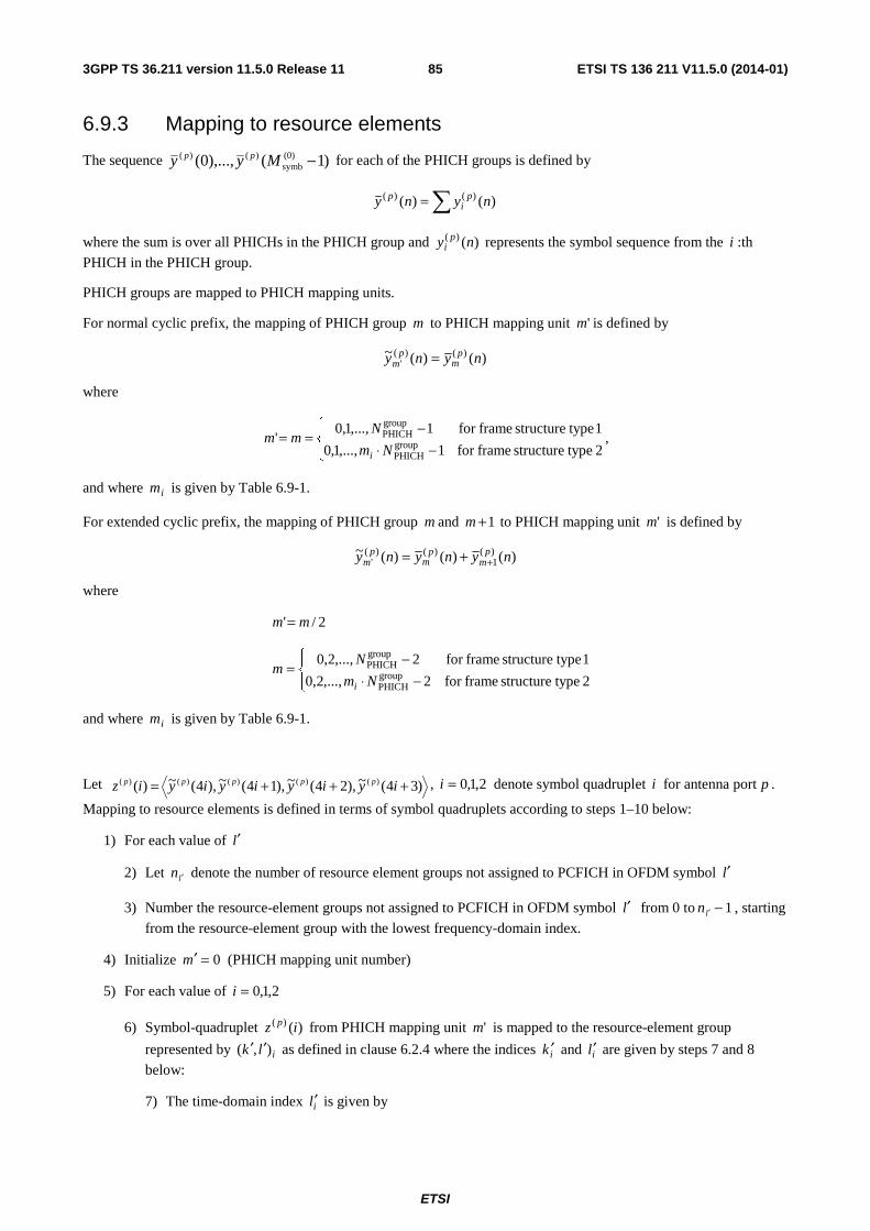
ETSI
ETSI TS 136 211 V11.5.0 (2014-01)853GPP TS 36.211 version 11.5.0 Release 11
6.9.3 Mapping to resource elements
The sequence )1(),...,0( (0)symb
)()( −Myy pp for each of the PHICH groups is defined by
∑= )()( )()( nyny pi
p
where the sum is over all PHICHs in the PHICH group and )()( ny pi represents the symbol sequence from the i :th
PHICH in the PHICH group.
PHICH groups are mapped to PHICH mapping units.
For normal cyclic prefix, the mapping of PHICH group m to PHICH mapping unit 'm is defined by
)()(~ )()(' nyny p
mp
m =
where
⎪⎩
⎪⎨⎧
−⋅−==
2 typestructure framefor 1,...,1,0
1 typestructure framefor 1,...,1,0' group
PHICH
groupPHICH
Nm
Nmm
i
,
and where im is given by Table 6.9-1.
For extended cyclic prefix, the mapping of PHICH group m and 1+m to PHICH mapping unit 'm is defined by
)()()(~ )(1
)()(' nynyny p
mp
mp
m ++=
where
2/' mm =
⎪⎩
⎪⎨⎧
−⋅−=
2 typestructure framefor 2,...,2,0
1 typestructure framefor 2,...,2,0groupPHICH
groupPHICH
Nm
Nm
i
and where im is given by Table 6.9-1.
Let )34(~),24(~),14(~),4(~)( )()()()()( +++= iyiyiyiyiz ppppp , 2,1,0=i denote symbol quadruplet i for antenna port p .
Mapping to resource elements is defined in terms of symbol quadruplets according to steps 1–10 below:
1) For each value of l′
2) Let ln ′ denote the number of resource element groups not assigned to PCFICH in OFDM symbol l′
3) Number the resource-element groups not assigned to PCFICH in OFDM symbol l′ from 0 to 1ln ′ − , starting
from the resource-element group with the lowest frequency-domain index.
4) Initialize 0=′m (PHICH mapping unit number)
5) For each value of 2,1,0=i
6) Symbol-quadruplet )()( iz p from PHICH mapping unit 'm is mapped to the resource-element group
represented by ilk ),( ′′ as defined in clause 6.2.4 where the indices ik ′ and il′ are given by steps 7 and 8
below:
7) The time-domain index il′ is given by
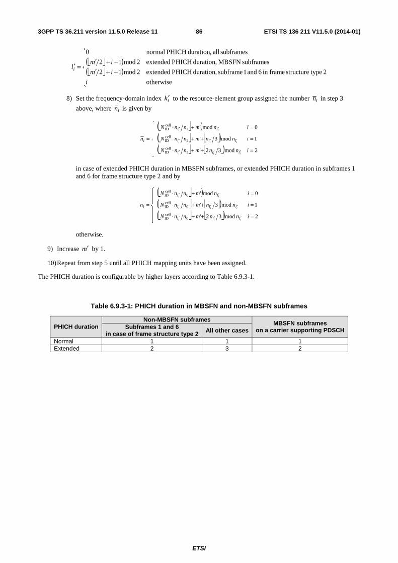
ETSI
ETSI TS 136 211 V11.5.0 (2014-01)863GPP TS 36.211 version 11.5.0 Release 11
⎣ ⎦( )⎣ ⎦( )
⎪⎪
⎩
⎪⎪
⎨
⎧
++′++′
=′
otherwise
2 typestructure framein 6 and 1 subframe duration, PHICH extended2mod12
subframes MBSFN duration, PHICH extended2mod12
subframes all duration, PHICH normal0
i
im
imli
8) Set the frequency-domain index ik ′ to the resource-element group assigned the number in in step 3
above, where in is given by
⎣ ⎦( )⎣ ⎦ ⎣ ⎦( )⎣ ⎦ ⎣ ⎦( )⎪
⎪
⎩
⎪⎪
⎨
⎧
=++⋅
=++⋅
=+⋅
=
′′′
′′′
′′
2mod32'
1mod3'
0mod'
1cellID
1cellID
1cellID
innmnnN
innmnnN
inmnnN
n
iii
iii
ii
lll
lll
ll
i
in case of extended PHICH duration in MBSFN subframes, or extended PHICH duration in subframes 1 and 6 for frame structure type 2 and by
⎣ ⎦( )⎣ ⎦ ⎣ ⎦( )⎣ ⎦ ⎣ ⎦( )⎪
⎪
⎩
⎪⎪
⎨
⎧
=++⋅
=++⋅
=+⋅
=
′′′
′′′
′′
2mod32'
1mod3'
0mod'
0cellID
0cellID
0cellID
innmnnN
innmnnN
inmnnN
n
iii
iii
ii
lll
lll
ll
i
otherwise.
9) Increase m′ by 1.
10) Repeat from step 5 until all PHICH mapping units have been assigned.
The PHICH duration is configurable by higher layers according to Table 6.9.3-1.
Table 6.9.3-1: PHICH duration in MBSFN and non-MBSFN subframes
PHICH duration Non-MBSFN subframes
MBSFN subframes on a carrier supporting PDSCH Subframes 1 and 6
in case of frame structure type 2 All other cases
Normal 1 1 1 Extended 2 3 2
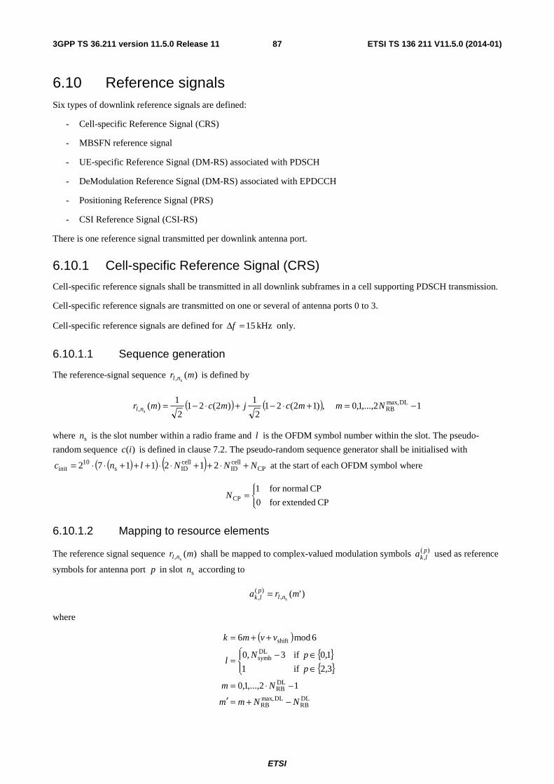
ETSI
ETSI TS 136 211 V11.5.0 (2014-01)873GPP TS 36.211 version 11.5.0 Release 11
6.10 Reference signals Six types of downlink reference signals are defined:
- Cell-specific Reference Signal (CRS)
- MBSFN reference signal
- UE-specific Reference Signal (DM-RS) associated with PDSCH
- DeModulation Reference Signal (DM-RS) associated with EPDCCH
- Positioning Reference Signal (PRS)
- CSI Reference Signal (CSI-RS)
There is one reference signal transmitted per downlink antenna port.
6.10.1 Cell-specific Reference Signal (CRS)
Cell-specific reference signals shall be transmitted in all downlink subframes in a cell supporting PDSCH transmission.
Cell-specific reference signals are transmitted on one or several of antenna ports 0 to 3.
Cell-specific reference signals are defined for kHz 15=Δf only.
6.10.1.1 Sequence generation
The reference-signal sequence )(s, mr nl is defined by
( ) ( ) 12,...,1,0 ,)12(212
1)2(21
2
1)( DLmax,
RB, s−=+⋅−+⋅−= Nmmcjmcmr nl
where sn is the slot number within a radio frame and l is the OFDM symbol number within the slot. The pseudo-
random sequence )(ic is defined in clause 7.2. The pseudo-random sequence generator shall be initialised with
( )( ) ( ) CPcellID
cellIDs
10init 2121172 NNNlnc +⋅++⋅⋅+++⋅⋅= at the start of each OFDM symbol where
⎩⎨⎧
=CP extendedfor 0
CP normalfor 1CPN
6.10.1.2 Mapping to resource elements
The reference signal sequence )(s, mr nl shall be mapped to complex-valued modulation symbols )(
,plka used as reference
symbols for antenna port p in slot sn according to
)'(s,
)(, mra nlplk =
where
( ){ }{ }
DLRB
DLmax,RB
DLRB
DLsymb
shift
12,...,1,0
3,2 if1
1,0 if3,0
6mod6
NNmm
Nm
p
pNl
vvmk
−+=′
−⋅=
⎪⎩
⎪⎨⎧
∈∈−=
++=
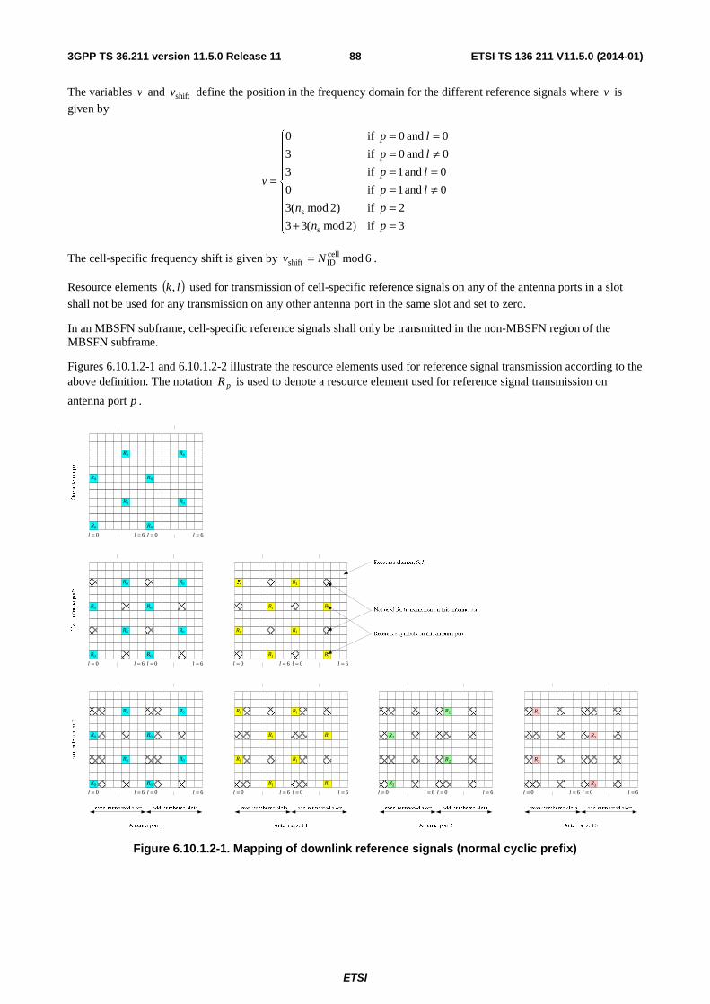
ETSI
ETSI TS 136 211 V11.5.0 (2014-01)883GPP TS 36.211 version 11.5.0 Release 11
The variables v and shiftv define the position in the frequency domain for the different reference signals where v is
given by
⎪⎪⎪⎪
⎩
⎪⎪⎪⎪
⎨
⎧
=+=
≠===≠===
=
3 if)2mod(33
2 if)2mod(3
0 and 1 if0
0 and 1 if3
0 and 0 if3
0 and 0 if0
s
s
pn
pn
lp
lp
lp
lp
v
The cell-specific frequency shift is given by 6modcellIDshift Nv = .
Resource elements ( )lk, used for transmission of cell-specific reference signals on any of the antenna ports in a slot
shall not be used for any transmission on any other antenna port in the same slot and set to zero.
In an MBSFN subframe, cell-specific reference signals shall only be transmitted in the non-MBSFN region of the MBSFN subframe.
Figures 6.10.1.2-1 and 6.10.1.2-2 illustrate the resource elements used for reference signal transmission according to the above definition. The notation pR is used to denote a resource element used for reference signal transmission on
antenna port p .
0=l
0R
0R
0R
0R
6=l 0=l
0R
0R
0R
0R
6=l
One antenna port
Two antenna ports
0=l
0R
0R
0R
0R
6=l 0=l
0R
0R
0R
0R
6=l 0=l
1R
1R
1R
6=l 0=l
1R
1R
1R
1R
6=l
0=l
0R
0R
0R
0R
6=l 0=l
0R
0R
0R
0R
6=l 0=l
1R
1R
1R
1R
6=l 0=l
1R
1R
1R
1R
6=l
Four antenna ports
0=l 6=l 0=l
2R
6=l 0=l 6=l 0=l 6=l
2R
2R
2R
3R
3R
3R
3R
Figure 6.10.1.2-1. Mapping of downlink reference signals (normal cyclic prefix)
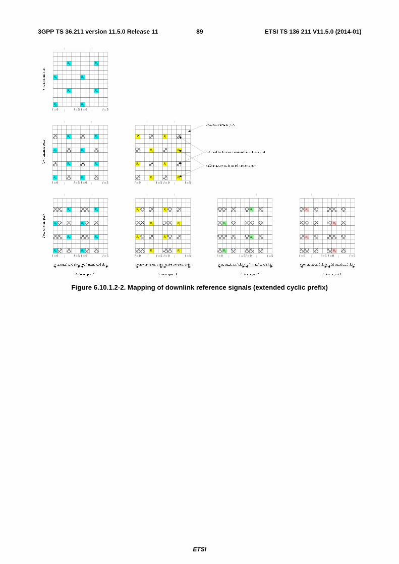
ETSI
ETSI TS 136 211 V11.5.0 (2014-01)893GPP TS 36.211 version 11.5.0 Release 11
0=l
0R
0R
0R
0R
5=l 0=l
0R
0R
0R
0R
5=l
One antenna port
Two antenna ports
Resource element (k,l)
Not used for transmission on this antenna port
Reference symbols on this antenna port
0=l
0R
0R
0R
0R
5=l 0=l
0R
0R
0R
0R
5=l 0=l
1R
1R
1R
1R
5=l 0=l
1R
1R
1R
1R
5=l
0=l
0R
0R
0R
0R
5=l 0=l
0R
0R
0R
0R
5=l 0=l
1R
1R
1R
1R
5=l 0=l
1R
1R
1R
1R
5=l
Four antenna ports
0=l 5=l 0=l
2R
5=l 0=l 5=l 0=l 5=l
2R
2R
2R
3R
3R
3R
3R
even-numbered slots odd-numbered slots
Antenna port 0 Antenna port 1 Antenna port 2 Antenna port 3
even-numbered slots odd-numbered slots even-numbered slots odd-numbered slots even-numbered slots odd-numbered slots
Figure 6.10.1.2-2. Mapping of downlink reference signals (extended cyclic prefix)
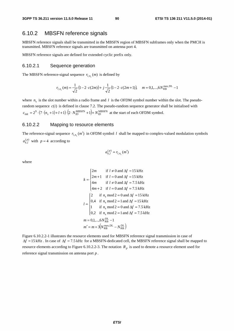
ETSI
ETSI TS 136 211 V11.5.0 (2014-01)903GPP TS 36.211 version 11.5.0 Release 11
6.10.2 MBSFN reference signals
MBSFN reference signals shall be transmitted in the MBSFN region of MBSFN subframes only when the PMCH is transmitted. MBSFN reference signals are transmitted on antenna port 4.
MBSFN reference signals are defined for extended cyclic prefix only.
6.10.2.1 Sequence generation
The MBSFN reference-signal sequence )(s, mr nl is defined by
( ) ( ) 16,...,1,0 ,)12(212
1)2(21
2
1)( DLmax,
RB, s−=+⋅−+⋅−= Nmmcjmcmr nl
where sn is the slot number within a radio frame and l is the OFDM symbol number within the slot. The pseudo-
random sequence )(ic is defined in clause 7.2. The pseudo-random sequence generator shall be initialised with
( )( ) ( ) MBSFNID
MBSFNID
9init 121172 NNlnc s ++⋅⋅+++⋅⋅= at the start of each OFDM symbol.
6.10.2.2 Mapping to resource elements
The reference-signal sequence )(s, mr nl ′ in OFDM symbol l shall be mapped to complex-valued modulation symbols
)(,plka with 4=p according to
)(s,
)(, mra nlplk ′=
where
( )DLRB
DLmax,RB
DLRB
s
s
s
s
3
16,...,1,0
kHz 5.7 and 12mod if2,0
kHz 5.7 and 02mod if1
kHz 15 and 12mod if4,0
kHz 15 and 02mod if2
kHz 5.7 and 0 if24
kHz 5.7 and 0 if4
kHz 15 and 0 if12
kHz 15 and 0 if2
NNmm
Nm
fn
fn
fn
fn
l
flm
flm
flm
flm
k
−+=′
−=
⎪⎪
⎩
⎪⎪
⎨
⎧
=Δ==Δ==Δ==Δ=
=
⎪⎪
⎩
⎪⎪
⎨
⎧
=Δ=+=Δ≠=Δ=+=Δ≠
=
Figure 6.10.2.2-1 illustrates the resource elements used for MBSFN reference signal transmission in case of kHz 15=Δf . In case of kHz 5.7=Δf for a MBSFN-dedicated cell, the MBSFN reference signal shall be mapped to
resource elements according to Figure 6.10.2.2-3. The notation pR is used to denote a resource element used for
reference signal transmission on antenna port p .
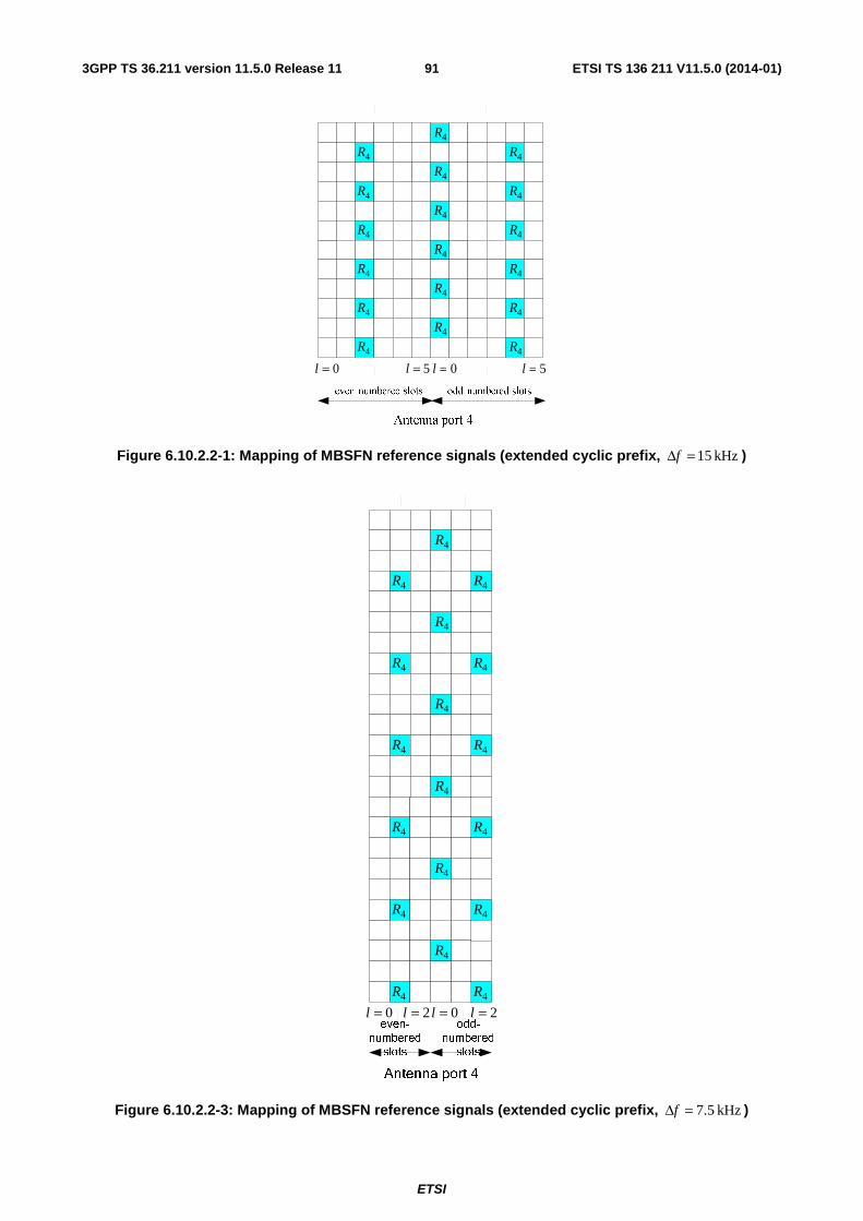
ETSI
ETSI TS 136 211 V11.5.0 (2014-01)913GPP TS 36.211 version 11.5.0 Release 11
0=l 5=l 0=l 5=l4R
4R
4R
4R
4R
4R
4R
4R
4R
4R
4R
4R
4R
4R
4R
4R
4R
4R
Figure 6.10.2.2-1: Mapping of MBSFN reference signals (extended cyclic prefix, kHz 15=Δf )
0=l 2=l 0=l 2=leven-
numbered
slots
Antenna port 4
4R
4R
4R
4R
4R
4R
4R
4R
4R
odd-
numbered
slots
4R
4R
4R
4R
4R
4R
4R
4R
4R
Figure 6.10.2.2-3: Mapping of MBSFN reference signals (extended cyclic prefix, kHz 5.7=Δf )
ETSI
ETSI TS 136 211 V11.5.0 (2014-01)923GPP TS 36.211 version 11.5.0 Release 11
6.10.3 UE-specific reference signals associated with PDSCH
UE-specific reference signals associated with PDSCH
- are transmitted on antenna port(s) 5=p , 7=p , 8=p or 6,...,8,7 += υp , where υ is the number of layers
used for transmission of the PDSCH;
- are present and are a valid reference for PDSCH demodulation only if the PDSCH transmission is associated with the corresponding antenna port according to clause 7.1 of 3GPP TS 36.213 [4];
- are transmitted only on the physical resource blocks upon which the corresponding PDSCH is mapped.
A UE-specific reference signal associated with PDSCH is not transmitted in resource elements ( )lk, in which one of
the physical channels or physical signals other than the UE-specific reference signals defined in 6.1 are transmitted using resource elements with the same index pair ( )lk, regardless of their antenna port p .
6.10.3.1 Sequence generation
For antenna port 5, the UE-specific reference-signal sequence )(s
mrn is defined by
( ) ( ) 11210 ,)12(212
1)2(21
2
1)( PDSCH
RBs−=+⋅−+⋅−= N,...,,mmcjmcmrn
where PDSCHRBN denotes the bandwidth in resource blocks of the corresponding PDSCH transmission. The pseudo-
random sequence )(ic is defined in clause 7.2. The pseudo-random sequence generator shall be initialised with
⎣ ⎦( ) ( ) RNTI16cell
IDsinit 21212 nNnc +⋅+⋅+= at the start of each subframe where RNTIn is as described in clause 7.1
3GPP TS 36.213 [4].
For any of the antenna ports { }6,...,8,7 +∈ υp , the reference-signal sequence )(mr is defined by
( ) ( )⎪⎩
⎪⎨⎧
−−=+⋅−+⋅−=
prefix cyclic extended11610
prefix cyclic normal11210 ,)12(21
2
1)2(21
2
1)(
DLmax,RB
DLmax,RB
N,...,,
N,...,,mmcjmcmr .
The pseudo-random sequence )(ic is defined in clause 7.2. The pseudo-random sequence generator shall be initialised
with
⎣ ⎦( ) ( ) SCID16)(
IDsinit 21212/ SCID nnnc n +⋅+⋅+=
at the start of each subframe.
The quantities )(IDin , 1,0=i , are given by
- cellID
)(ID Nn i = if no value for inDMRS,
ID is provided by higher layers or if DCI format 1A, 2B or 2C is used for the
DCI associated with the PDSCH transmission
- ii nn DMRS,ID
)(ID = otherwise
The value of SCIDn is zero unless specified otherwise. For a PDSCH transmission on ports 7 or 8, SCIDn is given by the
DCI format 2B, 2C or 2D in 3GPP TS 36.212 [3] associated with the PDSCH transmission. In the case of DCI format 2B, SCIDn is indicated by the scrambling identity field according to Table 6.10.3.1-1. In the
case of DCI format 2C or 2D, SCIDn is given by Table 5.3.3.1.5C-1 in 3GPP TS 36.212 [3].
ETSI
ETSI TS 136 211 V11.5.0 (2014-01)933GPP TS 36.211 version 11.5.0 Release 11
Table 6.10.3.1-1: Mapping of scrambling identity field in DCI format 2B to SCIDn values for antenna ports 7 and 8
Scrambling identity field in DCI format 2B
(3GPP TS 36.212 [3]) SCIDn
0 0 1 1
6.10.3.2 Mapping to resource elements
For antenna port 5, in a physical resource block with frequency-domain index BPRn assigned for the corresponding
PDSCH transmission, the reference signal sequence )(s
mrn shall be mapped to complex-valued modulation symbols
)(,plka with 5=p in a subframe according to:
Normal cyclic prefix:
)'3( PDSCHRB
)(, s
mNlra nplk +⋅′⋅=
{ }{ }
13,...,1,0'
12mod if2,3
02mod if1,0
35
22
16
03
6,5 if4mod)2(4m'
3,2 if'4
mod)(
PDSCHRB
s
s
shift
shift
PRBRBsc
RBsc
−=⎩⎨⎧
==
=′
⎪⎪
⎩
⎪⎪
⎨
⎧
=′=′=′=′
=
⎩⎨⎧
∈++∈+
=′
⋅+′=
Nm
n
nl
l
l
l
l
l
lv
lvmk
nNNkk
Extended cyclic prefix:
)'4( PDSCHRB
)(, s
mNlra nplk +⋅′⋅=
14,...,1,0'
12mod if1,2
02mod if0
11
}2,0{4
1 if3mod)2(3m'
4 if'3
mod)(
PDSCHRB
s
s
shift
shift
PRBRBsc
RBsc
−=⎩⎨⎧
==
=′
⎩⎨⎧
=′∈′
=
⎩⎨⎧
=++=+
=′
⋅+′=
Nm
n
nl
l
ll
lv
lvmk
nNNkk
where 'm is the counter of UE-specific reference signal resource elements within a respective OFDM symbol of the PDSCH transmission.
The cell-specific frequency shift is given by 3modcellIDshift Nv = .
The mapping shall be in increasing order of the frequency-domain index BPRn of the physical resource blocks assigned
for the corresponding PDSCH transmission. The quantity PDSCHRBN denotes the bandwidth in resource blocks of the
corresponding PDSCH transmission.
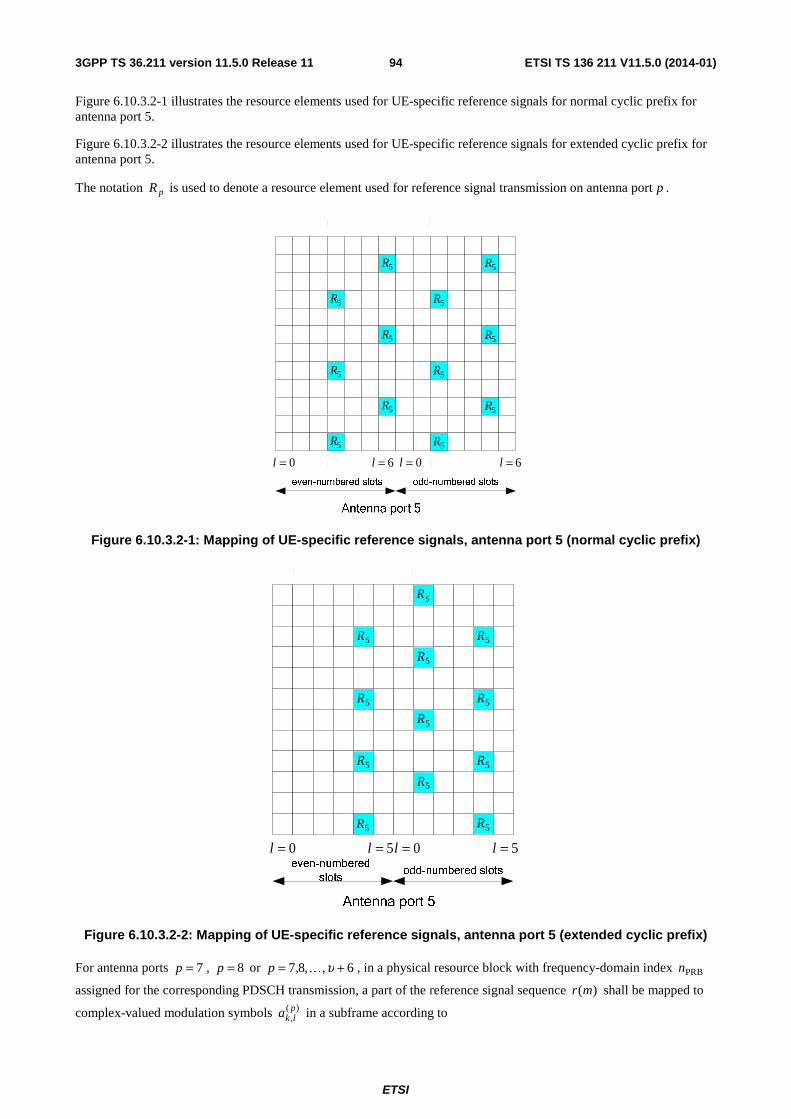
ETSI
ETSI TS 136 211 V11.5.0 (2014-01)943GPP TS 36.211 version 11.5.0 Release 11
Figure 6.10.3.2-1 illustrates the resource elements used for UE-specific reference signals for normal cyclic prefix for antenna port 5.
Figure 6.10.3.2-2 illustrates the resource elements used for UE-specific reference signals for extended cyclic prefix for antenna port 5.
The notation pR is used to denote a resource element used for reference signal transmission on antenna port p .
0=l
5R
5R
5R
5R
5R
5R
5R
5R
5R
5R
5R
5R
0=l 6=l6=l
Figure 6.10.3.2-1: Mapping of UE-specific reference signals, antenna port 5 (normal cyclic prefix)
0=l
5R
5R
0=l 5=l5=l
5R
5R
5R
5R
5R
5R
5R
5R
5R
5R
Figure 6.10.3.2-2: Mapping of UE-specific reference signals, antenna port 5 (extended cyclic prefix)
For antenna ports 7=p , 8=p or 6,,8,7 += υKp , in a physical resource block with frequency-domain index BPRn
assigned for the corresponding PDSCH transmission, a part of the reference signal sequence )(mr shall be mapped to
complex-valued modulation symbols )(,plka in a subframe according to
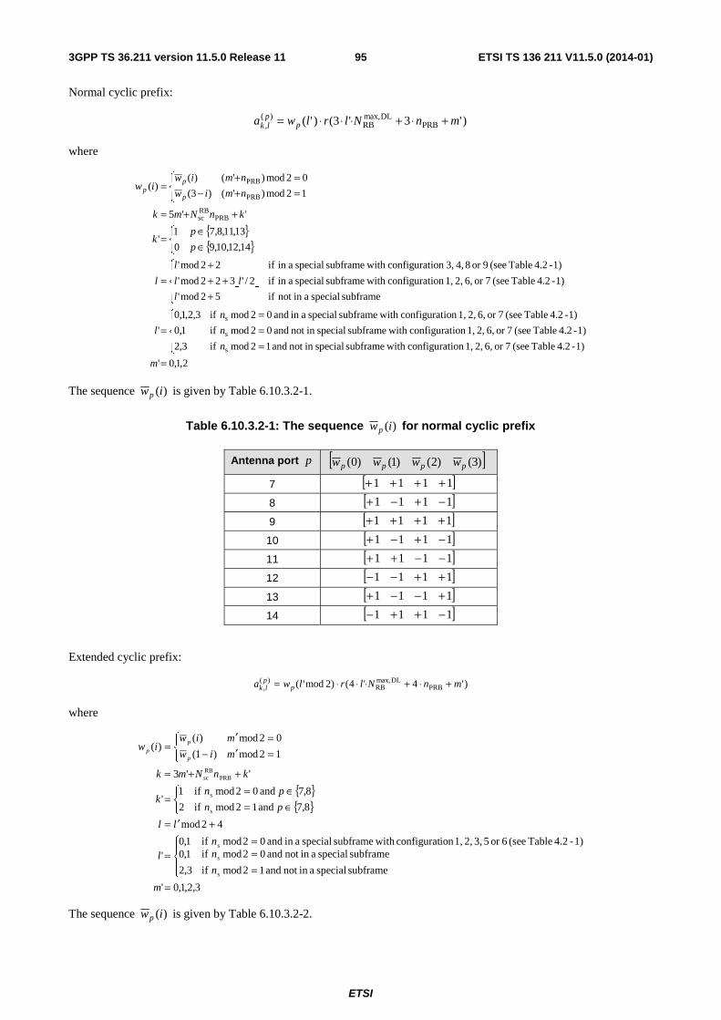
ETSI
ETSI TS 136 211 V11.5.0 (2014-01)953GPP TS 36.211 version 11.5.0 Release 11
Normal cyclic prefix:
)'3'3()'( PRBDLmax,
RB)(
, mnNlrlwa pplk +⋅+⋅⋅⋅=
where
{ }{ }
⎣ ⎦
2,1,0'
1)-4.2 Table (see 7or 6, 2, 1,ion configurat with subframe specialin not and 12mod if3,2
1)-4.2 Table (see 7or 6, 2, 1,ion configurat with subframe specialin not and 02mod if1,0
1)-4.2 Table (see 7or 6, 2, 1,ion configurat with subframe special ain and 02mod if3,2,1,0
'
subframe special ain not if52mod'
1)-4.2 Table (see 7or 6, 2, 1,ion configurat with subframe special ain if2/'322mod'
1)-4.2 Table (see 9or 8 4, 3,ion configurat with subframe special ain if22mod'
14,12,10,90
13,11,8,71'
''5
12mod)'()3(
02mod)'()()(
s
s
s
PRBRBsc
PRB
PRB
=
⎪⎩
⎪⎨
⎧
===
=
⎪⎩
⎪⎨
⎧
+++
+=
⎩⎨⎧
∈∈
=
++=⎩⎨⎧
=+−=+
=
m
n
n
n
l
l
ll
l
l
p
pk
knNmk
nmiw
nmiwiw
p
pp
The sequence )(iwp is given by Table 6.10.3.2-1.
Table 6.10.3.2-1: The sequence )(iwp for normal cyclic prefix
Antenna port p [ ])3()2()1()0( pppp wwww
7 [ ]1111 ++++
8 [ ]1111 −+−+
9 [ ]1111 ++++
10 [ ]1111 −+−+
11 [ ]1111 −−++
12 [ ]1111 ++−−
13 [ ]1111 +−−+
14 [ ]1111 −++−
Extended cyclic prefix:
)'4'4()2mod'( PRBDLmax,
RB)(
, mnNlrlwa pplk +⋅+⋅⋅⋅=
where
{ }{ }
3,2,1,0'
subframe speciala innot and 12mod if
subframe speciala innot and 02mod if
3,2
1,01)-4.2 Table (see 6or 5 3, 2, 1, ionconfigurat withsubframe speciala in and 02mod if1,0
'
42mod
8,7 and 12mod if2
8,7 and 02mod if1'
''3
12mod)1(
02mod)()(
s
s
s
s
s
PRBRBsc
=
⎪⎩
⎪⎨
⎧
===
=
+′=⎩⎨⎧
∈=∈=
=
++=⎩⎨⎧
=′−=′
=
m
n
nn
l
ll
pn
pnk
knNmk
miw
miwiw
p
p
p
The sequence )(iwp is given by Table 6.10.3.2-2.
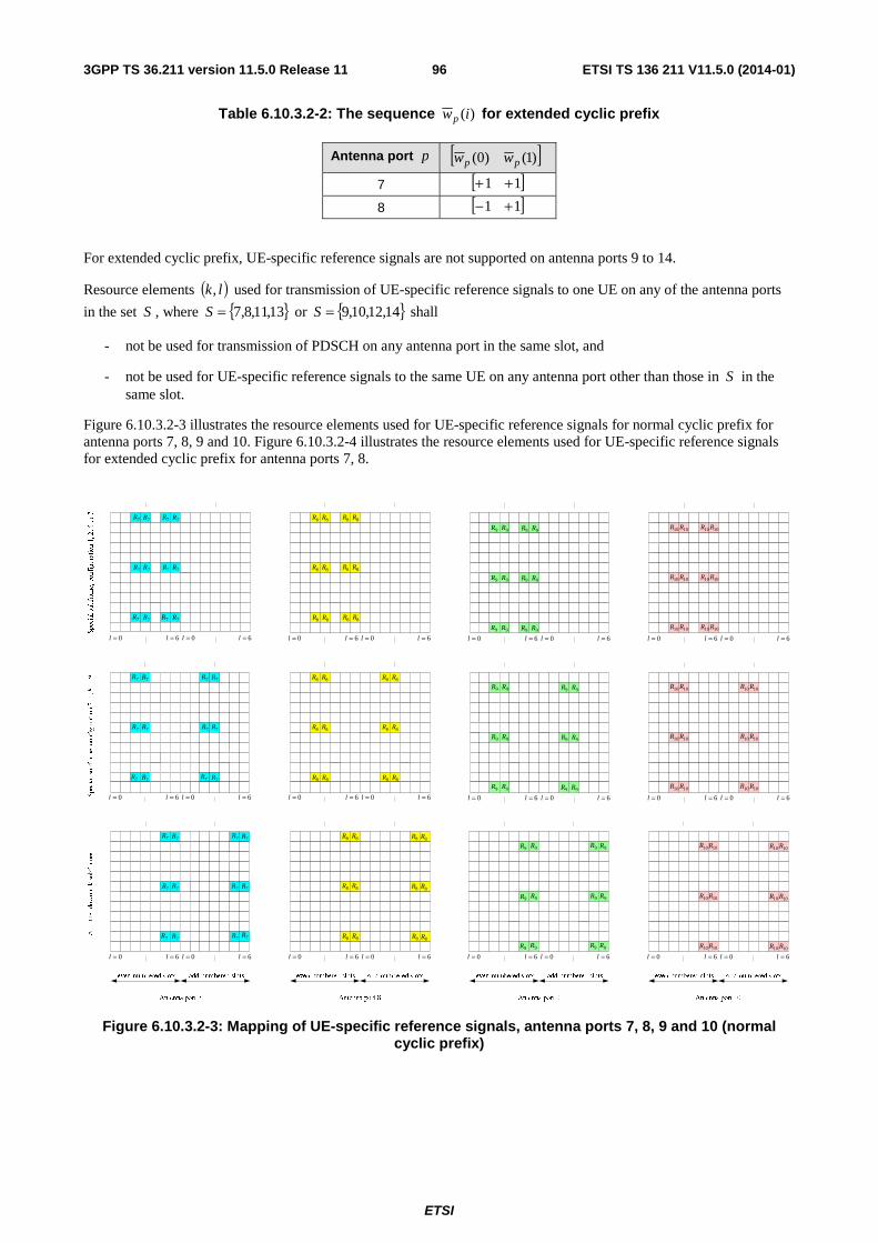
ETSI
ETSI TS 136 211 V11.5.0 (2014-01)963GPP TS 36.211 version 11.5.0 Release 11
Table 6.10.3.2-2: The sequence )(iwp for extended cyclic prefix
Antenna port p [ ])1()0( pp ww
7 [ ]11 ++
8 [ ]11 +−
For extended cyclic prefix, UE-specific reference signals are not supported on antenna ports 9 to 14.
Resource elements ( )lk, used for transmission of UE-specific reference signals to one UE on any of the antenna ports
in the set S , where { }13,11,8,7=S or { }14,12,10,9=S shall
- not be used for transmission of PDSCH on any antenna port in the same slot, and
- not be used for UE-specific reference signals to the same UE on any antenna port other than those in S in the same slot.
Figure 6.10.3.2-3 illustrates the resource elements used for UE-specific reference signals for normal cyclic prefix for antenna ports 7, 8, 9 and 10. Figure 6.10.3.2-4 illustrates the resource elements used for UE-specific reference signals for extended cyclic prefix for antenna ports 7, 8.
0=l 6=l 0=l 6=lSpecial subframe, configuration 1, 2, 6 or 7
Special subframe, configuration 3, 4, 8 or 9
0=l 6=l 0=l 6=l 0=l 6=l 0=l 6=l
0=l 6=l 0=l 6=l 0=l 6=l 0=l 6=l
All other downlink subframes
0=l 6=l 0=l 6=l 0=l 6=l 0=l 6=l
7R 7R 7R 7R
7R7R7R7R
7R 7R 7R 7R 8R 8R 8R 8R
8R 8R 8R 8R
8R 8R 8R 8R
9R 9R 9R 9R
9R 9R 9R 9R
9R 9R 9R 9R
10R 10R 10R 10R
10R 10R 10R 10R
10R 10R 10R 10R
7R 7R
7R7R
7R 7R
7R 7R
7R7R
7R 7R 8R 8R
8R 8R
8R 8R
8R 8R
8R 8R
8R 8R
7R 7R
7R7R
7R 7R
7R 7R
7R7R
7R 7R 8R 8R
8R 8R
8R 8R
0=l 6=l 0=l 6=l
8R 8R
8R 8R
8R 8R
0=l 6=l 0=l 6=l 0=l 6=l 0=l 6=l
0=l 6=l 0=l 6=l 0=l 6=l 0=l 6=l
9R 9R
9R 9R
9R 9R
9R 9R
9R 9R
9R 9R
10R 10R
10R 10R
10R 10R
10R 10R
10R 10R
10R 10R
9R 9R
9R 9R
9R 9R
9R 9R
9R 9R
9R 9R
10R 10R
10R 10R
10R 10R
10R 10R
10R 10R
10R 10R
Figure 6.10.3.2-3: Mapping of UE-specific reference signals, antenna ports 7, 8, 9 and 10 (normal cyclic prefix)
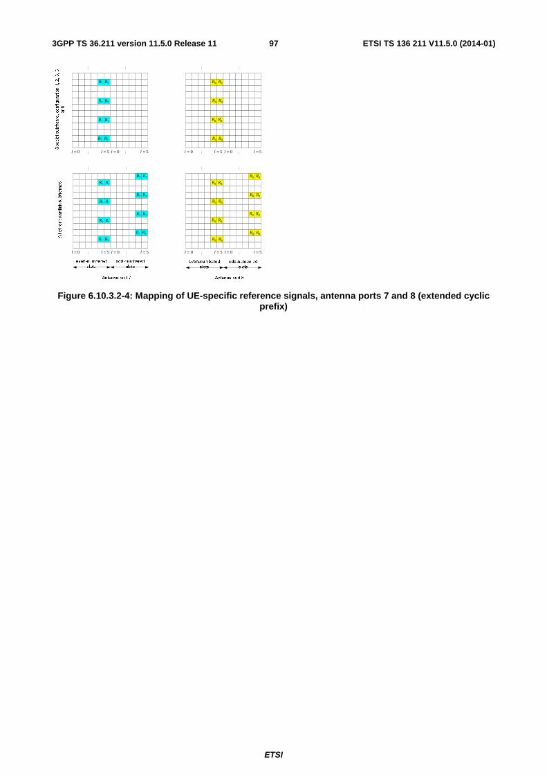
ETSI
ETSI TS 136 211 V11.5.0 (2014-01)973GPP TS 36.211 version 11.5.0 Release 11
Special subframe, configuration 1, 2, 3, 5
or 6
0=l 5=l 0=l 5=l 0=l 5=l 0=l 5=l
0=l 5=l 0=l 5=l 0=l
8R
5=l 0=l 5=l
All other downlink subframes
7R 7R
7R 7R
7R 7R
7R 7R
7R 7R
7R 7R
7R 7R
7R 7R
8R
8R 8R
8R 8R
8R 8R
8R 8R
8R 8R
8R 8R
8R 8R
7R 7R
7R 7R
7R 7R
7R 7R
8R 8R
8R 8R
8R 8R
8R 8R
Figure 6.10.3.2-4: Mapping of UE-specific reference signals, antenna ports 7 and 8 (extended cyclic prefix)
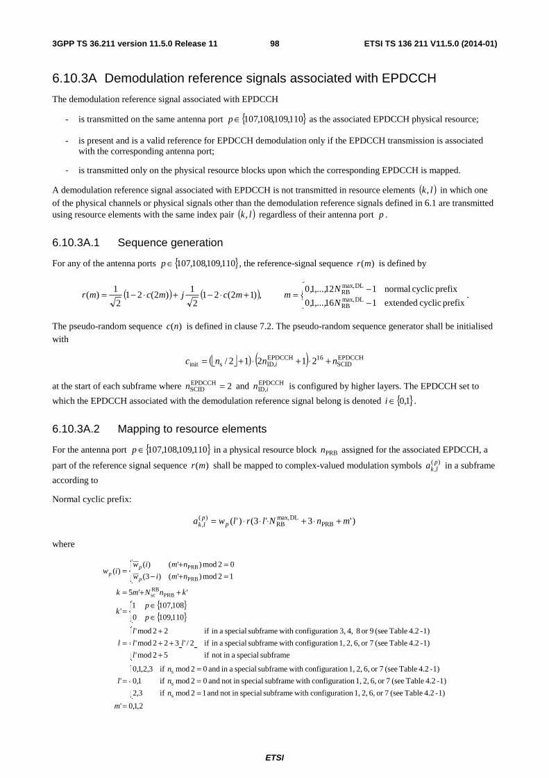
ETSI
ETSI TS 136 211 V11.5.0 (2014-01)983GPP TS 36.211 version 11.5.0 Release 11
6.10.3A Demodulation reference signals associated with EPDCCH
The demodulation reference signal associated with EPDCCH
- is transmitted on the same antenna port { }110,109,108,107∈p as the associated EPDCCH physical resource;
- is present and is a valid reference for EPDCCH demodulation only if the EPDCCH transmission is associated with the corresponding antenna port;
- is transmitted only on the physical resource blocks upon which the corresponding EPDCCH is mapped.
A demodulation reference signal associated with EPDCCH is not transmitted in resource elements ( )lk, in which one
of the physical channels or physical signals other than the demodulation reference signals defined in 6.1 are transmitted using resource elements with the same index pair ( )lk, regardless of their antenna port p .
6.10.3A.1 Sequence generation
For any of the antenna ports { }110,109,108,107∈p , the reference-signal sequence )(mr is defined by
( ) ( )⎪⎩
⎪⎨⎧
−−=+⋅−+⋅−=
prefix cyclic extended11610
prefix cyclic normal11210 ,)12(21
2
1)2(21
2
1)(
DLmax,RB
DLmax,RB
N,...,,
N,...,,mmcjmcmr .
The pseudo-random sequence )(nc is defined in clause 7.2. The pseudo-random sequence generator shall be initialised
with
⎣ ⎦( ) ( ) EPDCCHSCID
16EPDCCHIDsinit 21212/ nnnc ,i +⋅+⋅+=
at the start of each subframe where 2EPDCCHSCID =n and EPDCCH
ID,in is configured by higher layers. The EPDCCH set to
which the EPDCCH associated with the demodulation reference signal belong is denoted { }1,0∈i .
6.10.3A.2 Mapping to resource elements
For the antenna port { }110,109,108,107∈p in a physical resource block PRBn assigned for the associated EPDCCH, a
part of the reference signal sequence )(mr shall be mapped to complex-valued modulation symbols )(,plka in a subframe
according to
Normal cyclic prefix:
)'3'3()'( PRBDLmax,
RB)(
, mnNlrlwa pplk +⋅+⋅⋅⋅=
where
{ }{ }
⎣ ⎦
2,1,0'
1)-4.2 Table (see 7or 6, 2, 1,ion configurat with subframe specialin not and 12mod if3,2
1)-4.2 Table (see 7or 6, 2, 1,ion configurat with subframe specialin not and 02mod if1,0
1)-4.2 Table (see 7or 6, 2, 1,ion configurat with subframe special ain and 02mod if3,2,1,0
'
subframe special ain not if52mod'
1)-4.2 Table (see 7or 6, 2, 1,ion configurat with subframe special ain if2/'322mod'
1)-4.2 Table (see 9or 8 4, 3,ion configurat with subframe special ain if22mod'
110,1090
108,1071'
''5
12mod)'()3(
02mod)'()()(
s
s
s
PRBRBsc
PRB
PRB
=
⎪⎩
⎪⎨
⎧
===
=
⎪⎩
⎪⎨
⎧
+++
+=
⎩⎨⎧
∈∈
=
++=⎩⎨⎧
=+−=+
=
m
n
n
n
l
l
ll
l
l
p
pk
knNmk
nmiw
nmiwiw
p
pp
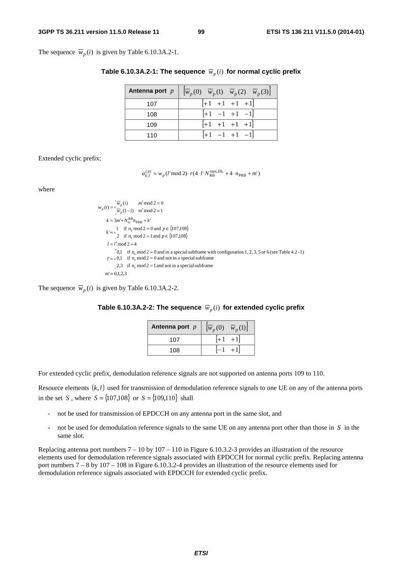
ETSI
ETSI TS 136 211 V11.5.0 (2014-01)993GPP TS 36.211 version 11.5.0 Release 11
The sequence )(iwp is given by Table 6.10.3A.2-1.
Table 6.10.3A.2-1: The sequence )(iwp for normal cyclic prefix
Antenna port p [ ])3()2()1()0( pppp wwww
107 [ ]1111 ++++
108 [ ]1111 −+−+
109 [ ]1111 ++++
110 [ ]1111 −+−+
Extended cyclic prefix:
)'4'4()2mod'( PRBDLmax,
RB)(
, mnNlrlwa pplk +⋅+⋅⋅⋅=
where
{ }{ }
3,2,1,0'
subframe special ain not and 12mod if
subframe special ain not and 02mod if
3,2
1,01)-4.2 Table (see 6or 5 3, 2, 1,ion configurat with subframe special ain and 02mod if1,0
'
42mod
108,107 and 12mod if2
108,107 and 02mod if1'
''3
12mod)1(
02mod)()(
s
s
s
s
s
PRBRBsc
=
⎪⎩
⎪⎨
⎧
===
=
+′=⎩⎨⎧
∈=∈=
=
++=⎩⎨⎧
=′−=′
=
m
n
nn
l
ll
pn
pnk
knNmk
miw
miwiw
p
pp
The sequence )(iwp is given by Table 6.10.3A.2-2.
Table 6.10.3A.2-2: The sequence )(iwp for extended cyclic prefix
Antenna port p [ ])1()0( pp ww
107 [ ]11 ++
108 [ ]11 +−
For extended cyclic prefix, demodulation reference signals are not supported on antenna ports 109 to 110.
Resource elements ( )lk, used for transmission of demodulation reference signals to one UE on any of the antenna ports
in the set S , where { }108,107=S or { }110,109=S shall
- not be used for transmission of EPDCCH on any antenna port in the same slot, and
- not be used for demodulation reference signals to the same UE on any antenna port other than those in S in the same slot.
Replacing antenna port numbers 7 – 10 by 107 – 110 in Figure 6.10.3.2-3 provides an illustration of the resource elements used for demodulation reference signals associated with EPDCCH for normal cyclic prefix. Replacing antenna port numbers 7 – 8 by 107 – 108 in Figure 6.10.3.2-4 provides an illustration of the resource elements used for demodulation reference signals associated with EPDCCH for extended cyclic prefix.
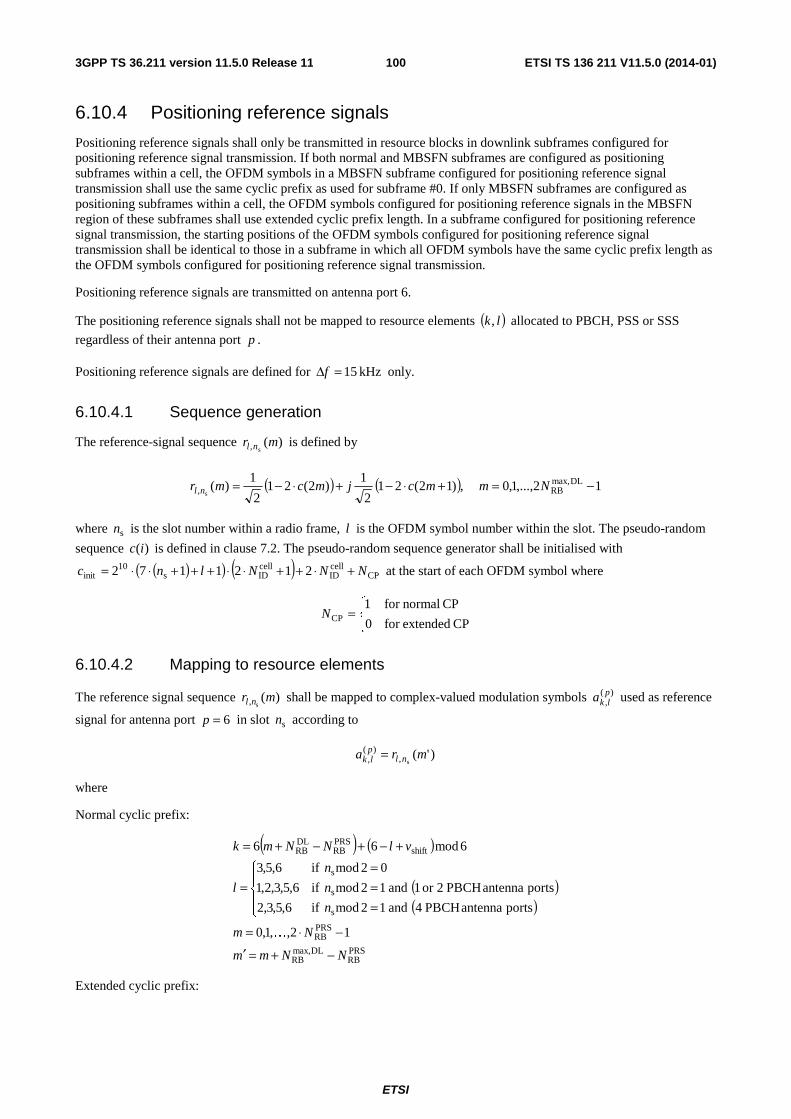
ETSI
ETSI TS 136 211 V11.5.0 (2014-01)1003GPP TS 36.211 version 11.5.0 Release 11
6.10.4 Positioning reference signals
Positioning reference signals shall only be transmitted in resource blocks in downlink subframes configured for positioning reference signal transmission. If both normal and MBSFN subframes are configured as positioning subframes within a cell, the OFDM symbols in a MBSFN subframe configured for positioning reference signal transmission shall use the same cyclic prefix as used for subframe #0. If only MBSFN subframes are configured as positioning subframes within a cell, the OFDM symbols configured for positioning reference signals in the MBSFN region of these subframes shall use extended cyclic prefix length. In a subframe configured for positioning reference signal transmission, the starting positions of the OFDM symbols configured for positioning reference signal transmission shall be identical to those in a subframe in which all OFDM symbols have the same cyclic prefix length as the OFDM symbols configured for positioning reference signal transmission.
Positioning reference signals are transmitted on antenna port 6.
The positioning reference signals shall not be mapped to resource elements ( )lk, allocated to PBCH, PSS or SSS
regardless of their antenna port p .
Positioning reference signals are defined for kHz 15=Δf only.
6.10.4.1 Sequence generation
The reference-signal sequence )(s, mr nl is defined by
( ) ( ) 12,...,1,0 ,)12(212
1)2(21
2
1)( DLmax,
RB, s−=+⋅−+⋅−= Nmmcjmcmr nl
where sn is the slot number within a radio frame, l is the OFDM symbol number within the slot. The pseudo-random
sequence )(ic is defined in clause 7.2. The pseudo-random sequence generator shall be initialised with
( )( ) ( ) CPcellID
cellIDs
10init 2121172 NNNlnc +⋅++⋅⋅+++⋅⋅= at the start of each OFDM symbol where
⎩⎨⎧
=CP extendedfor 0
CP normalfor 1CPN
6.10.4.2 Mapping to resource elements
The reference signal sequence )(s, mr nl shall be mapped to complex-valued modulation symbols )(
,plka used as reference
signal for antenna port 6=p in slot sn according to
)'(s,
)(, mra nlplk =
where
Normal cyclic prefix:
( ) ( )
( )( )
PRSRB
DLmax,RB
PRSRB
s
s
s
shiftPRSRB
DLRB
12,,1,0
portsantennaPBCH4and12modif6,5,3,2
portsantennaPBCH2or1and12modif6,5,3,2,1
02modif6,5,3
6mod66
NNmm
Nm
n
n
n
l
vlNNmk
−+=′
−⋅=
⎪⎩
⎪⎨
⎧
===
=
+−+−+=
K
Extended cyclic prefix:
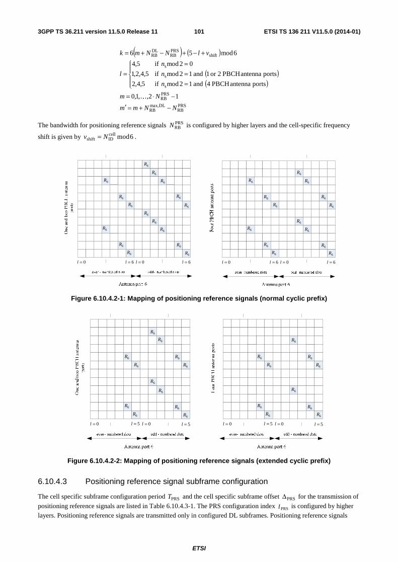
ETSI
ETSI TS 136 211 V11.5.0 (2014-01)1013GPP TS 36.211 version 11.5.0 Release 11
( ) ( )
( )( )
PRSRB
DLmax,RB
PRSRB
s
s
s
shiftPRSRB
DLRB
12,,1,0
portsantennaPBCH4and12modif5,4,2
portsantennaPBCH2or1and12modif5,4,2,1
02modif5,4
6mod56
NNmm
Nm
n
n
n
l
vlNNmk
−+=′
−⋅=
⎪⎩
⎪⎨
⎧
===
=
+−+−+=
K
The bandwidth for positioning reference signals PRSRBN is configured by higher layers and the cell-specific frequency
shift is given by 6modcellIDshift Nv = .
0=l 6=l 0=l 6=l
Four PBCH antenna ports
6R
6R
6R
6R
6R
6R
6R
6R
6R
6R
6R
6R
6R
6R
0=l 6=l 0=l 6=l
One and two PBCH antenna
ports
6R
6R
6R
6R
6R
6R
6R
6R
6R
6R
6R
6R
6R
6R
6R
6R
Figure 6.10.4.2-1: Mapping of positioning reference signals (normal cyclic prefix)
0=l 5=l 0=l 5=l
6R
6R
6R
6R
6R
6R
6R
6R
6R
6R
0=l 5=l 0=l 5=l
6R
6R
6R
6R
6R
6R
6R
6R
6R
6R
6R
6R
Figure 6.10.4.2-2: Mapping of positioning reference signals (extended cyclic prefix)
6.10.4.3 Positioning reference signal subframe configuration
The cell specific subframe configuration period PRST and the cell specific subframe offset PRSΔ for the transmission of
positioning reference signals are listed in Table 6.10.4.3-1. The PRS configuration index PRSI is configured by higher
layers. Positioning reference signals are transmitted only in configured DL subframes. Positioning reference signals
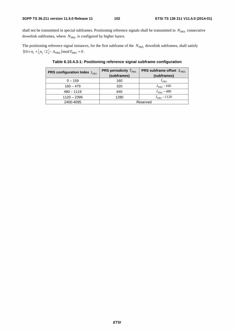
ETSI
ETSI TS 136 211 V11.5.0 (2014-01)1023GPP TS 36.211 version 11.5.0 Release 11
shall not be transmitted in special subframes. Positioning reference signals shall be transmitted in PRSN consecutive
downlink subframes, where PRSN is configured by higher layers.
The positioning reference signal instances, for the first subframe of the PRSN downlink subframes, shall satisfy
⎣ ⎦( ) 0mod2/10 PRSPRSsf =Δ−+× Tnn .
Table 6.10.4.3-1: Positioning reference signal subframe configuration
PRS configuration Index PRSI PRS periodicity PRST (subframes)
PRS subframe offset PRSΔ (subframes)
0 – 159 160 PRSI
160 – 479 320 160PRS −I
480 – 1119 640 480PRS −I
1120 – 2399 1280 1120PRS −I
2400-4095 Reserved
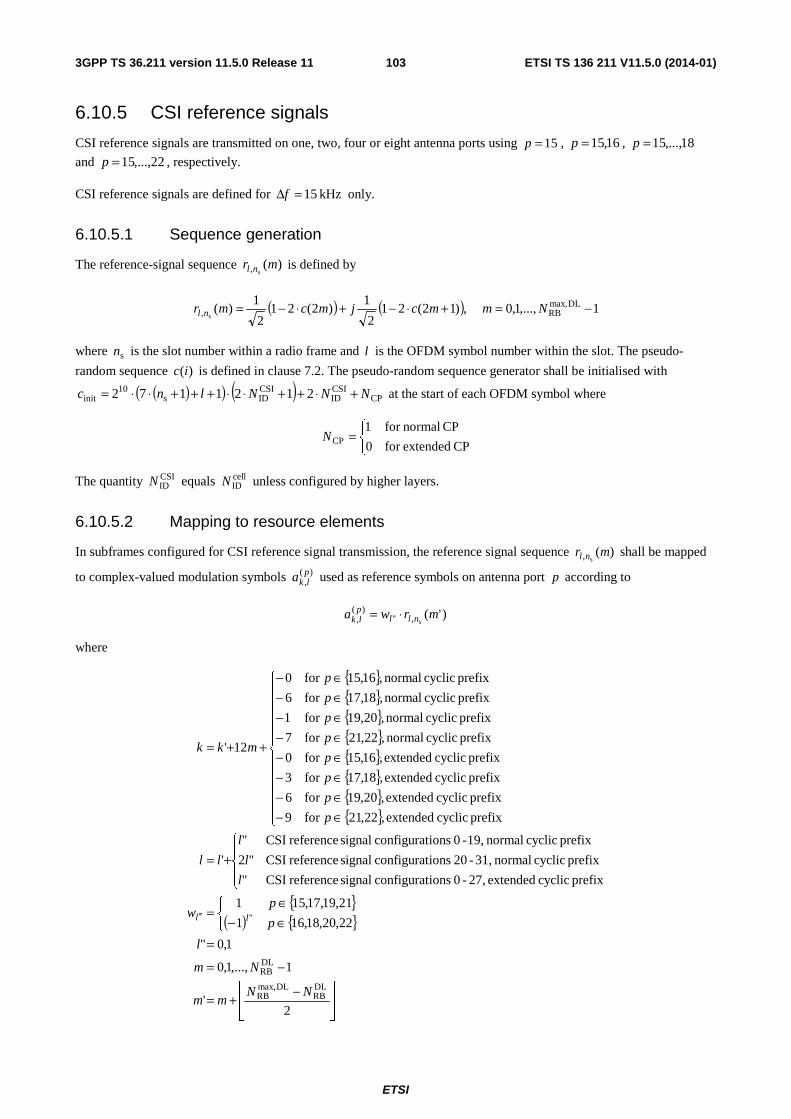
ETSI
ETSI TS 136 211 V11.5.0 (2014-01)1033GPP TS 36.211 version 11.5.0 Release 11
6.10.5 CSI reference signals
CSI reference signals are transmitted on one, two, four or eight antenna ports using 15=p , 16,15=p , 18,...,15=p
and 22,...,15=p , respectively.
CSI reference signals are defined for kHz 15=Δf only.
6.10.5.1 Sequence generation
The reference-signal sequence )(s, mr nl is defined by
( ) ( ) 1,...,1,0 ,)12(212
1)2(21
2
1)( DLmax,
RB, s−=+⋅−+⋅−= Nmmcjmcmr nl
where sn is the slot number within a radio frame and l is the OFDM symbol number within the slot. The pseudo-
random sequence )(ic is defined in clause 7.2. The pseudo-random sequence generator shall be initialised with
( )( ) ( ) CPCSIID
CSIIDs
10init 2121172 NNNlnc +⋅++⋅⋅+++⋅⋅= at the start of each OFDM symbol where
⎩⎨⎧
=CP extendedfor 0
CP normalfor 1CPN
The quantity CSIIDN equals cell
IDN unless configured by higher layers.
6.10.5.2 Mapping to resource elements
In subframes configured for CSI reference signal transmission, the reference signal sequence )(s, mr nl shall be mapped
to complex-valued modulation symbols )(,plka used as reference symbols on antenna port p according to
)'(s,"
)(, mrwa nllplk ⋅=
where
{ }{ }{ }{ }{ }{ }{ }{ }
{ }( ) { }
⎥⎥⎦
⎥
⎢⎢⎣
⎢ −+=
−=
=⎩⎨⎧
∈−∈
=
⎪⎩
⎪⎨
⎧
+=
⎪⎪⎪⎪⎪
⎩
⎪⎪⎪⎪⎪
⎨
⎧
∈−∈−∈−∈−∈−∈−∈−∈−
++=
′′
2'
1,...,1,0
1,0"
22,20,18,161
21,19,17,151
prefix cyclic extended 27,-0 ionsconfigurat signal reference CSI"
prefix cyclic normal 31,-20 ionsconfigurat signal reference CSI"2
prefix cyclic normal 19,-0 ionsconfigurat signal reference CSI"
'
prefix cyclic extended,22,21for 9
prefix cyclic extended,20,19for 6
prefix cyclic extended,18,17for 3
prefix cyclic extended,16,15for 0
prefix cyclic normal,22,21for 7
prefix cyclic normal,20,19for 1
prefix cyclic normal,18,17for 6
prefix cyclic normal,16,15for 0
12'
DLRB
DLmax,RB
DLRB
"
NNmm
Nm
l
p
pw
l
l
l
ll
p
p
p
p
p
p
p
p
mkk
ll
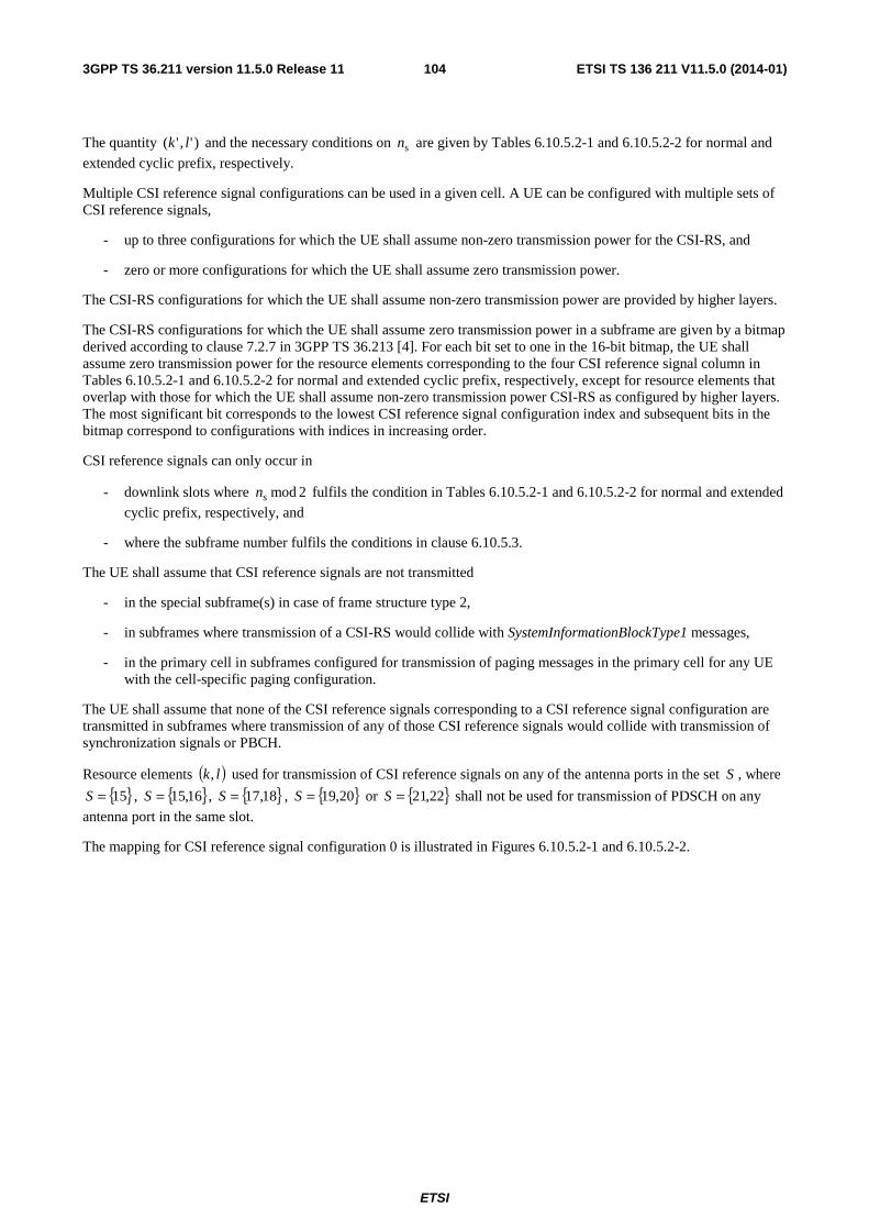
ETSI
ETSI TS 136 211 V11.5.0 (2014-01)1043GPP TS 36.211 version 11.5.0 Release 11
The quantity )','( lk and the necessary conditions on sn are given by Tables 6.10.5.2-1 and 6.10.5.2-2 for normal and
extended cyclic prefix, respectively.
Multiple CSI reference signal configurations can be used in a given cell. A UE can be configured with multiple sets of CSI reference signals,
- up to three configurations for which the UE shall assume non-zero transmission power for the CSI-RS, and
- zero or more configurations for which the UE shall assume zero transmission power.
The CSI-RS configurations for which the UE shall assume non-zero transmission power are provided by higher layers.
The CSI-RS configurations for which the UE shall assume zero transmission power in a subframe are given by a bitmap derived according to clause 7.2.7 in 3GPP TS 36.213 [4]. For each bit set to one in the 16-bit bitmap, the UE shall assume zero transmission power for the resource elements corresponding to the four CSI reference signal column in Tables 6.10.5.2-1 and 6.10.5.2-2 for normal and extended cyclic prefix, respectively, except for resource elements that overlap with those for which the UE shall assume non-zero transmission power CSI-RS as configured by higher layers. The most significant bit corresponds to the lowest CSI reference signal configuration index and subsequent bits in the bitmap correspond to configurations with indices in increasing order.
CSI reference signals can only occur in
- downlink slots where 2modsn fulfils the condition in Tables 6.10.5.2-1 and 6.10.5.2-2 for normal and extended
cyclic prefix, respectively, and
- where the subframe number fulfils the conditions in clause 6.10.5.3.
The UE shall assume that CSI reference signals are not transmitted
- in the special subframe(s) in case of frame structure type 2,
- in subframes where transmission of a CSI-RS would collide with SystemInformationBlockType1 messages,
- in the primary cell in subframes configured for transmission of paging messages in the primary cell for any UE with the cell-specific paging configuration.
The UE shall assume that none of the CSI reference signals corresponding to a CSI reference signal configuration are transmitted in subframes where transmission of any of those CSI reference signals would collide with transmission of synchronization signals or PBCH.
Resource elements ( )lk, used for transmission of CSI reference signals on any of the antenna ports in the set S , where
{ }15=S , { }16,15=S , { }18,17=S , { }20,19=S or { }22,21=S shall not be used for transmission of PDSCH on any
antenna port in the same slot.
The mapping for CSI reference signal configuration 0 is illustrated in Figures 6.10.5.2-1 and 6.10.5.2-2.
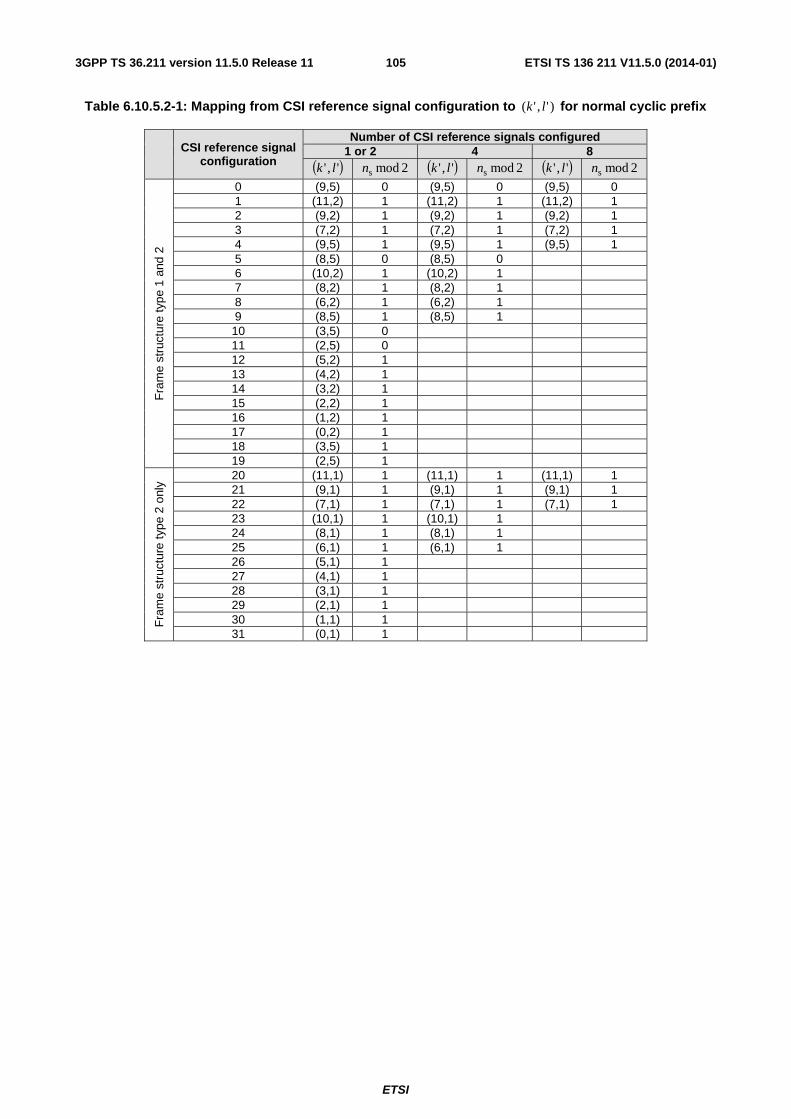
ETSI
ETSI TS 136 211 V11.5.0 (2014-01)1053GPP TS 36.211 version 11.5.0 Release 11
Table 6.10.5.2-1: Mapping from CSI reference signal configuration to )','( lk for normal cyclic prefix
CSI reference signal configuration
Number of CSI reference signals configured 1 or 2 4 8
( )',' lk 2modsn ( )',' lk 2modsn ( )',' lk 2modsn F
ram
e st
ruct
ure
type
1 a
nd 2
0 (9,5) 0 (9,5) 0 (9,5) 0 1 (11,2) 1 (11,2) 1 (11,2) 1 2 (9,2) 1 (9,2) 1 (9,2) 1 3 (7,2) 1 (7,2) 1 (7,2) 1 4 (9,5) 1 (9,5) 1 (9,5) 1 5 (8,5) 0 (8,5) 0 6 (10,2) 1 (10,2) 1 7 (8,2) 1 (8,2) 1 8 (6,2) 1 (6,2) 1 9 (8,5) 1 (8,5) 1 10 (3,5) 0 11 (2,5) 0 12 (5,2) 1 13 (4,2) 1 14 (3,2) 1 15 (2,2) 1 16 (1,2) 1 17 (0,2) 1 18 (3,5) 1 19 (2,5) 1
Fra
me
stru
ctur
e ty
pe 2
onl
y
20 (11,1) 1 (11,1) 1 (11,1) 1 21 (9,1) 1 (9,1) 1 (9,1) 1 22 (7,1) 1 (7,1) 1 (7,1) 1 23 (10,1) 1 (10,1) 1 24 (8,1) 1 (8,1) 1 25 (6,1) 1 (6,1) 1 26 (5,1) 1 27 (4,1) 1 28 (3,1) 1 29 (2,1) 1 30 (1,1) 1 31 (0,1) 1
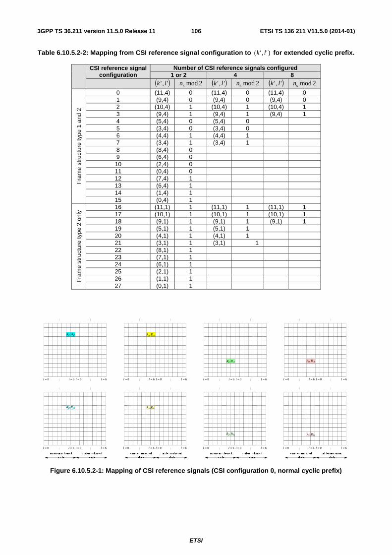
ETSI
ETSI TS 136 211 V11.5.0 (2014-01)1063GPP TS 36.211 version 11.5.0 Release 11
Table 6.10.5.2-2: Mapping from CSI reference signal configuration to )','( lk for extended cyclic prefix.
CSI reference signal
configuration Number of CSI reference signals configured
1 or 2 4 8 ( )',' lk 2modsn ( )',' lk 2modsn ( )',' lk 2modsn
Fra
me
stru
ctur
e ty
pe 1
and
2
0 (11,4) 0 (11,4) 0 (11,4) 0 1 (9,4) 0 (9,4) 0 (9,4) 0 2 (10,4) 1 (10,4) 1 (10,4) 1 3 (9,4) 1 (9,4) 1 (9,4) 1 4 (5,4) 0 (5,4) 0 5 (3,4) 0 (3,4) 0 6 (4,4) 1 (4,4) 1 7 (3,4) 1 (3,4) 1 8 (8,4) 0 9 (6,4) 0 10 (2,4) 0 11 (0,4) 0 12 (7,4) 1 13 (6,4) 1 14 (1,4) 1 15 (0,4) 1
Fra
me
stru
ctur
e ty
pe 2
onl
y
16 (11,1) 1 (11,1) 1 (11,1) 1 17 (10,1) 1 (10,1) 1 (10,1) 1 18 (9,1) 1 (9,1) 1 (9,1) 1 19 (5,1) 1 (5,1) 1 20 (4,1) 1 (4,1) 1 21 (3,1) 1 (3,1) 1 22 (8,1) 1 23 (7,1) 1 24 (6,1) 1 25 (2,1) 1 26 (1,1) 1 27 (0,1) 1
even-numbered
slots
odd-numbered
slots
even-numbered
slots
odd-numbered
slots
even-numbered
slots
odd-numbered
slots
even-numbered
slots
odd-numbered
slots
0=l 6=l 0=l 6=l 0=l 6=l 0=l 6=l 0=l 6=l 0=l 6=l 0=l 6=l 0=l 6=l
0=l 6=l 0=l 6=l 0=l 6=l 0=l 6=l 0=l 6=l 0=l 6=l 0=l 6=l 0=l 6=l
15R 15R 16R 16R
17R 17R 18R 18R
19R 19R 20R 20R
21R 21R 22R 22R
Figure 6.10.5.2-1: Mapping of CSI reference signals (CSI configuration 0, normal cyclic prefix)
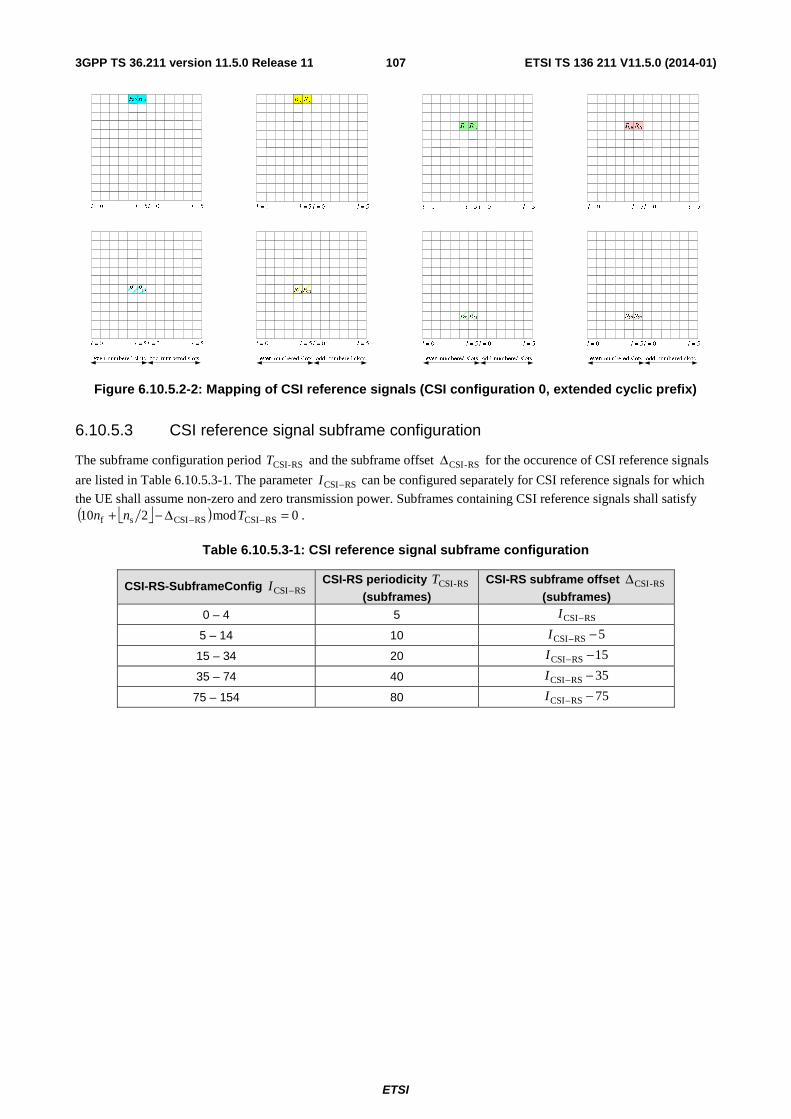
ETSI
ETSI TS 136 211 V11.5.0 (2014-01)1073GPP TS 36.211 version 11.5.0 Release 11
Figure 6.10.5.2-2: Mapping of CSI reference signals (CSI configuration 0, extended cyclic prefix)
6.10.5.3 CSI reference signal subframe configuration
The subframe configuration period RS-CSIT and the subframe offset RS-CSIΔ for the occurence of CSI reference signals
are listed in Table 6.10.5.3-1. The parameter RSCSI−I can be configured separately for CSI reference signals for which
the UE shall assume non-zero and zero transmission power. Subframes containing CSI reference signals shall satisfy
⎣ ⎦( ) 0mod210 RSCSIRSCSIsf =Δ−+ −− Tnn .
Table 6.10.5.3-1: CSI reference signal subframe configuration
CSI-RS-SubframeConfig RSCSI−I CSI-RS periodicity RS-CSIT (subframes)
CSI-RS subframe offset RS-CSIΔ (subframes)
0 – 4 5 RSCSI−I
5 – 14 10 5RSCSI −−I
15 – 34 20 15RSCSI −−I
35 – 74 40 35RSCSI −−I
75 – 154 80 75RSCSI −−I
ETSI
ETSI TS 136 211 V11.5.0 (2014-01)1083GPP TS 36.211 version 11.5.0 Release 11
6.11 Synchronization signals There are 504 unique physical-layer cell identities. The physical-layer cell identities are grouped into 168 unique physical-layer cell-identity groups, each group containing three unique identities. The grouping is such that each physical-layer cell identity is part of one and only one physical-layer cell-identity group. A physical-layer cell identity
(2)ID
(1)ID
cellID 3 NNN += is thus uniquely defined by a number (1)
IDN in the range of 0 to 167, representing the physical-layer
cell-identity group, and a number (2)IDN in the range of 0 to 2, representing the physical-layer identity within the
physical-layer cell-identity group.
6.11.1 Primary synchronization signal
6.11.1.1 Sequence generation
The sequence )(nd used for the primary synchronization signal is generated from a frequency-domain Zadoff-Chu
sequence according to
⎪⎩
⎪⎨
⎧
=
== ++−
+−
61,...,32,31
30,...,1,0)(63
)2)(1(
63
)1(
ne
nend nnuj
nunj
u π
π
where the Zadoff-Chu root sequence index u is given by Table 6.11.1.1-1.
Table 6.11.1.1-1: Root indices for the primary synchronization signal
(2)IDN Root index u
0 25 1 29 2 34
6.11.1.2 Mapping to resource elements
The mapping of the sequence to resource elements depends on the frame structure. The UE shall not assume that the primary synchronization signal is transmitted on the same antenna port as any of the downlink reference signals. The UE shall not assume that any transmission instance of the primary synchronization signal is transmitted on the same antenna port, or ports, used for any other transmission instance of the primary synchronization signal.
The sequence ( )nd shall be mapped to the resource elements according to
( )
231
61,...,0 ,
RBsc
DLRB
,
NNnk
nnda lk
+−=
==
For frame structure type 1, the primary synchronization signal shall be mapped to the last OFDM symbol in slots 0 and 10.
For frame structure type 2, the primary synchronization signal shall be mapped to the third OFDM symbol in subframes 1 and 6. Resource elements ),( lk in the OFDM symbols used for transmission of the primary synchronization signal
where
66,...63,62,1,...,4,52
31RBsc
DLRB
−−−=
+−=
n
NNnk
are reserved and not used for transmission of the primary synchronization signal.
ETSI
ETSI TS 136 211 V11.5.0 (2014-01)1093GPP TS 36.211 version 11.5.0 Release 11
6.11.2 Secondary synchronization signal
6.11.2.1 Sequence generation
The sequence )61(),...,0( dd used for the second synchronization signal is an interleaved concatenation of two length-31
binary sequences. The concatenated sequence is scrambled with a scrambling sequence given by the primary synchronization signal.
The combination of two length-31 sequences defining the secondary synchronization signal differs between subframe 0 and subframe 5 according to
( )( )( ) ( )( ) ( )⎪⎩
⎪⎨⎧
=+
⎪⎩
⎪⎨⎧
=
5 subframein )(
0 subframein )()12(
5 subframein )(
0 subframein )()2(
)(11
)(0
)(11
)(1
0)(
1
0)(
0
10
01
1
0
nzncns
nzncnsnd
ncns
ncnsnd
mm
mm
m
m
where 300 ≤≤ n . The indices 0m and 1m are derived from the physical-layer cell-identity group (1)IDN according to
⎣ ⎦( )
⎣ ⎦30,30
2)1(,2)1(
31mod131
31mod
(1)ID
(1)ID(1)
ID
01
0
NqqqN
qqqNm
mmm
mm
=′⎥⎥⎦
⎥
⎢⎢⎣
⎢ +′′+=++=′
+′+=′=
where the output of the above expression is listed in Table 6.11.2.1-1.
The two sequences )()(0
0 ns m and )()(1
1 ns m are defined as two different cyclic shifts of the m-sequence )(~ ns according
to
( )( )31mod)(~)(
31mod)(~)(
1)(
1
0)(
0
1
0
mnsns
mnsnsm
m
+=
+=
where )(21)(~ ixis −= , 300 ≤≤ i , is defined by
( ) 250 ,2mod)()2()5( ≤≤++=+ iixixix
with initial conditions 1)4(,0)3(,0)2(,0)1(,0)0( ===== xxxxx .
The two scrambling sequences )(0 nc and )(1 nc depend on the primary synchronization signal and are defined by two
different cyclic shifts of the m-sequence )(~ nc according to
)31mod)3((~)(
)31mod)((~)()2(
ID1
)2(ID0
++=
+=
Nncnc
Nncnc
where { }2,1,0)2(ID ∈N is the physical-layer identity within the physical-layer cell identity group (1)
IDN and
)(21)(~ ixic −= , 300 ≤≤ i , is defined by
( ) 250 ,2mod)()3()5( ≤≤++=+ iixixix
with initial conditions 1)4(,0)3(,0)2(,0)1(,0)0( ===== xxxxx .
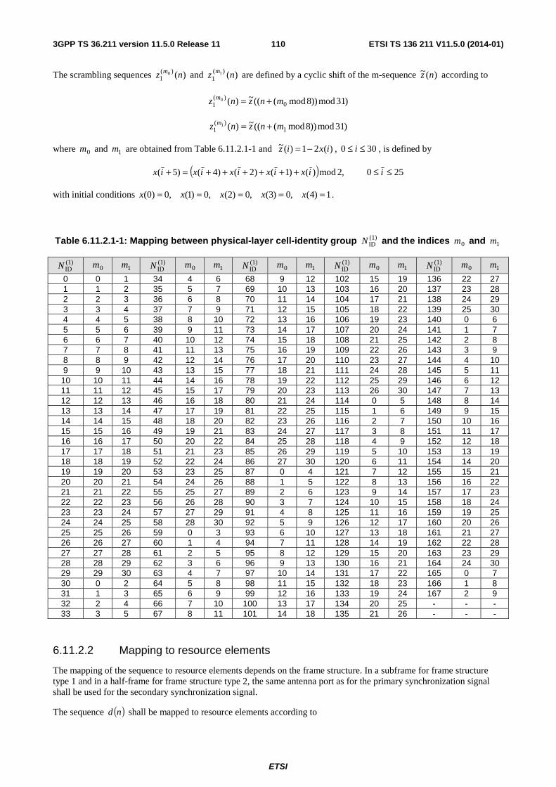
ETSI
ETSI TS 136 211 V11.5.0 (2014-01)1103GPP TS 36.211 version 11.5.0 Release 11
The scrambling sequences )()(1
0 nz m and )()(1
1 nz m are defined by a cyclic shift of the m-sequence )(~ nz according to
)31mod))8mod(((~)( 0)(
10 mnznz m +=
)31mod))8mod(((~)( 1)(
11 mnznz m +=
where 0m and 1m are obtained from Table 6.11.2.1-1 and )(21)(~ ixiz −= , 300 ≤≤ i , is defined by
( ) 250 ,2mod)()1()2()4()5( ≤≤++++++=+ iixixixixix
with initial conditions 1)4(,0)3(,0)2(,0)1(,0)0( ===== xxxxx .
Table 6.11.2.1-1: Mapping between physical-layer cell-identity group (1)IDN and the indices 0m and 1m
(1)IDN 0m 1m
(1)IDN 0m 1m
(1)IDN 0m 1m
(1)IDN 0m 1m
(1)IDN 0m 1m
0 0 1 34 4 6 68 9 12 102 15 19 136 22 27 1 1 2 35 5 7 69 10 13 103 16 20 137 23 28 2 2 3 36 6 8 70 11 14 104 17 21 138 24 29 3 3 4 37 7 9 71 12 15 105 18 22 139 25 30 4 4 5 38 8 10 72 13 16 106 19 23 140 0 6 5 5 6 39 9 11 73 14 17 107 20 24 141 1 7 6 6 7 40 10 12 74 15 18 108 21 25 142 2 8 7 7 8 41 11 13 75 16 19 109 22 26 143 3 9 8 8 9 42 12 14 76 17 20 110 23 27 144 4 10 9 9 10 43 13 15 77 18 21 111 24 28 145 5 11 10 10 11 44 14 16 78 19 22 112 25 29 146 6 12 11 11 12 45 15 17 79 20 23 113 26 30 147 7 13 12 12 13 46 16 18 80 21 24 114 0 5 148 8 14 13 13 14 47 17 19 81 22 25 115 1 6 149 9 15 14 14 15 48 18 20 82 23 26 116 2 7 150 10 16 15 15 16 49 19 21 83 24 27 117 3 8 151 11 17 16 16 17 50 20 22 84 25 28 118 4 9 152 12 18 17 17 18 51 21 23 85 26 29 119 5 10 153 13 19 18 18 19 52 22 24 86 27 30 120 6 11 154 14 20 19 19 20 53 23 25 87 0 4 121 7 12 155 15 21 20 20 21 54 24 26 88 1 5 122 8 13 156 16 22 21 21 22 55 25 27 89 2 6 123 9 14 157 17 23 22 22 23 56 26 28 90 3 7 124 10 15 158 18 24 23 23 24 57 27 29 91 4 8 125 11 16 159 19 25 24 24 25 58 28 30 92 5 9 126 12 17 160 20 26 25 25 26 59 0 3 93 6 10 127 13 18 161 21 27 26 26 27 60 1 4 94 7 11 128 14 19 162 22 28 27 27 28 61 2 5 95 8 12 129 15 20 163 23 29 28 28 29 62 3 6 96 9 13 130 16 21 164 24 30 29 29 30 63 4 7 97 10 14 131 17 22 165 0 7 30 0 2 64 5 8 98 11 15 132 18 23 166 1 8 31 1 3 65 6 9 99 12 16 133 19 24 167 2 9 32 2 4 66 7 10 100 13 17 134 20 25 - - - 33 3 5 67 8 11 101 14 18 135 21 26 - - -
6.11.2.2 Mapping to resource elements
The mapping of the sequence to resource elements depends on the frame structure. In a subframe for frame structure type 1 and in a half-frame for frame structure type 2, the same antenna port as for the primary synchronization signal shall be used for the secondary synchronization signal.
The sequence ( )nd shall be mapped to resource elements according to
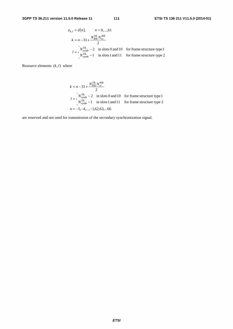
ETSI
ETSI TS 136 211 V11.5.0 (2014-01)1113GPP TS 36.211 version 11.5.0 Release 11
( )
⎪⎩
⎪⎨⎧
−−
=
+−=
==
2 typestructure framefor 11 and 1 slotsin 1
1 typestructure framefor 10 and 0 slotsin 2
231
61,...,0 ,
DLsymb
DLsymb
RBsc
DLRB
,
N
Nl
NNnk
nnda lk
Resource elements ),( lk where
66,...63,62,1,...,4,5
2 typestructure framefor 11 and 1 slotsin 1
1 typestructure framefor 10 and 0 slotsin 2
231
DLsymb
DLsymb
RBsc
DLRB
−−−=
⎪⎩
⎪⎨⎧
−−
=
+−=
n
N
Nl
NNnk
are reserved and not used for transmission of the secondary synchronization signal.
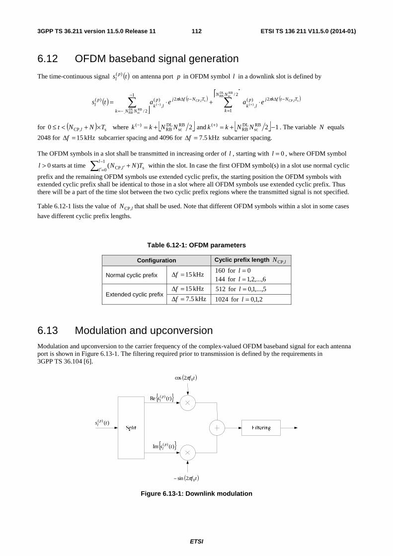
ETSI
ETSI TS 136 211 V11.5.0 (2014-01)1123GPP TS 36.211 version 11.5.0 Release 11
6.12 OFDM baseband signal generation
The time-continuous signal ( )ts pl
)( on antenna port p in OFDM symbol l in a downlink slot is defined by
( ) ( )
⎣ ⎦
( )⎡ ⎤∑∑
=
−Δ−
−=
−Δ ⋅+⋅= +−
2/
1
2)(,
1
2/
2)(,
)(
RBsc
DLRB
s,CP)(
RBsc
DLRB
s,CP)(
NN
k
TNtfkjplk
NNk
TNtfkjplk
pl
ll eaeats ππ
for ( ) s,CP0 TNNt l ×+<≤ where ⎣ ⎦2RBsc
DLRB
)( NNkk +=− and ⎣ ⎦ 12RBsc
DLRB
)( −+=+ NNkk . The variable N equals
2048 for kHz 15=Δf subcarrier spacing and 4096 for kHz 5.7=Δf subcarrier spacing.
The OFDM symbols in a slot shall be transmitted in increasing order of l , starting with 0=l , where OFDM symbol
0>l starts at time ∑−
=′ ′ +1
0 s,CP )(l
l l TNN within the slot. In case the first OFDM symbol(s) in a slot use normal cyclic
prefix and the remaining OFDM symbols use extended cyclic prefix, the starting position the OFDM symbols with extended cyclic prefix shall be identical to those in a slot where all OFDM symbols use extended cyclic prefix. Thus there will be a part of the time slot between the two cyclic prefix regions where the transmitted signal is not specified.
Table 6.12-1 lists the value of lN ,CP that shall be used. Note that different OFDM symbols within a slot in some cases
have different cyclic prefix lengths.
Table 6.12-1: OFDM parameters
Configuration Cyclic prefix length lN ,CP
Normal cyclic prefix kHz 15=Δf 0for 160 =l
6,...,2,1for 144 =l
Extended cyclic prefix kHz 15=Δf 5,...,1,0for 512 =l
kHz 5.7=Δf 2,1,0for 1024 =l
6.13 Modulation and upconversion Modulation and upconversion to the carrier frequency of the complex-valued OFDM baseband signal for each antenna port is shown in Figure 6.13-1. The filtering required prior to transmission is defined by the requirements in 3GPP TS 36.104 [6].
{ })(Re )( ts pl
{ })(Im )( ts pl
( )tf02cos π
( )tf02sin π−
)()( ts pl
Figure 6.13-1: Downlink modulation
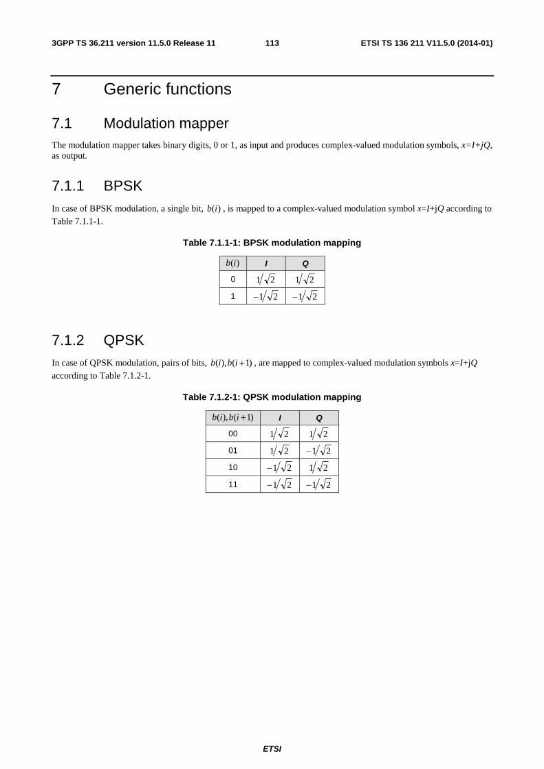
ETSI
ETSI TS 136 211 V11.5.0 (2014-01)1133GPP TS 36.211 version 11.5.0 Release 11
7 Generic functions
7.1 Modulation mapper The modulation mapper takes binary digits, 0 or 1, as input and produces complex-valued modulation symbols, x=I+jQ, as output.
7.1.1 BPSK In case of BPSK modulation, a single bit, )(ib , is mapped to a complex-valued modulation symbol x=I+jQ according to
Table 7.1.1-1.
Table 7.1.1-1: BPSK modulation mapping
)(ib I Q
0 21 21
1 21− 21−
7.1.2 QPSK In case of QPSK modulation, pairs of bits, )1(),( +ibib , are mapped to complex-valued modulation symbols x=I+jQ
according to Table 7.1.2-1.
Table 7.1.2-1: QPSK modulation mapping
)1(),( +ibib I Q
00 21 21
01 21 21−
10 21− 21
11 21− 21−
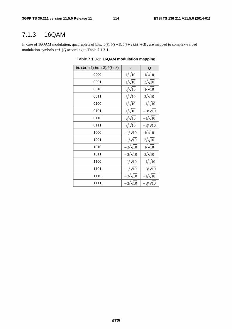
ETSI
ETSI TS 136 211 V11.5.0 (2014-01)1143GPP TS 36.211 version 11.5.0 Release 11
7.1.3 16QAM In case of 16QAM modulation, quadruplets of bits, )3(),2(),1(),( +++ ibibibib , are mapped to complex-valued
modulation symbols x=I+jQ according to Table 7.1.3-1.
Table 7.1.3-1: 16QAM modulation mapping
)3(),2(),1(),( +++ ibibibib I Q
0000 101 101
0001 101 103
0010 103 101
0011 103 103
0100 101 101−
0101 101 103−
0110 103 101−
0111 103 103−
1000 101− 101
1001 101− 103
1010 103− 101
1011 103− 103
1100 101− 101−
1101 101− 103−
1110 103− 101−
1111 103− 103−
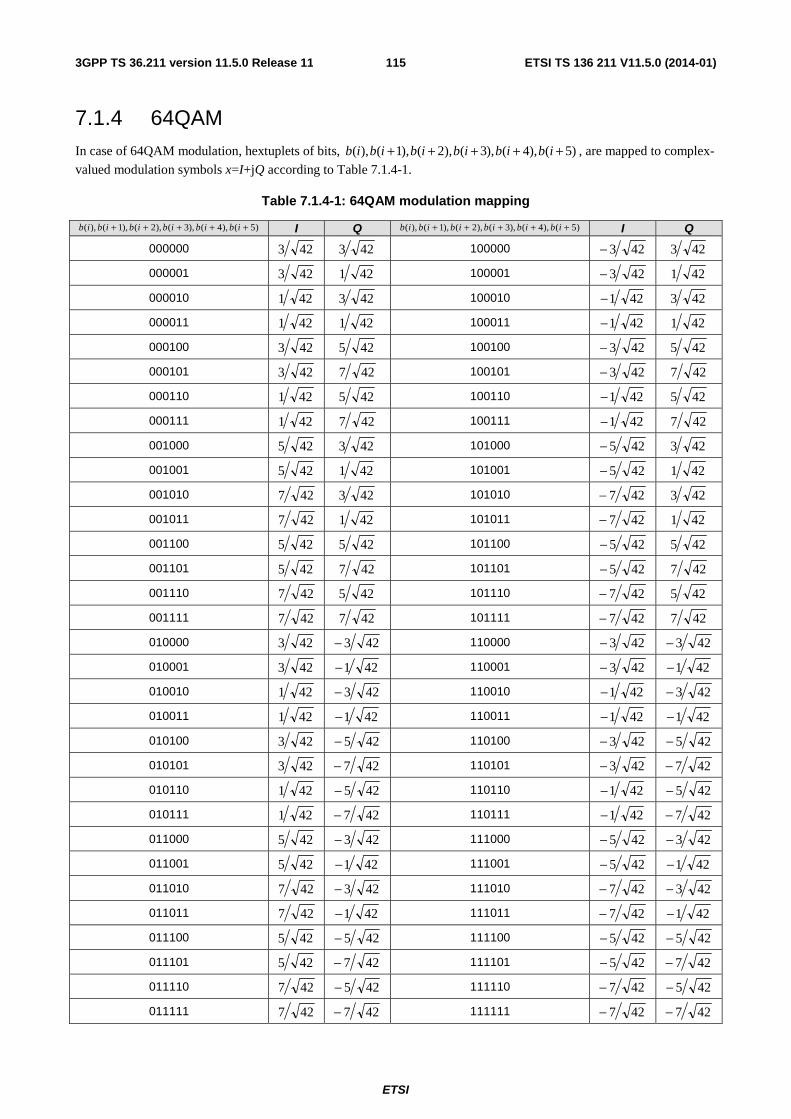
ETSI
ETSI TS 136 211 V11.5.0 (2014-01)1153GPP TS 36.211 version 11.5.0 Release 11
7.1.4 64QAM In case of 64QAM modulation, hextuplets of bits, )5(),4(),3(),2(),1(),( +++++ ibibibibibib , are mapped to complex-
valued modulation symbols x=I+jQ according to Table 7.1.4-1.
Table 7.1.4-1: 64QAM modulation mapping
)5(),4(),3(),2(),1(),( +++++ ibibibibibib I Q )5(),4(),3(),2(),1(),( +++++ ibibibibibib I Q
000000 423 423 100000 423− 423
000001 423 421 100001 423− 421
000010 421 423 100010 421− 423
000011 421 421 100011 421− 421
000100 423 425 100100 423− 425
000101 423 427 100101 423− 427
000110 421 425 100110 421− 425
000111 421 427 100111 421− 427
001000 425 423 101000 425− 423
001001 425 421 101001 425− 421
001010 427 423 101010 427− 423
001011 427 421 101011 427− 421
001100 425 425 101100 425− 425
001101 425 427 101101 425− 427
001110 427 425 101110 427− 425
001111 427 427 101111 427− 427
010000 423 423− 110000 423− 423−
010001 423 421− 110001 423− 421−
010010 421 423− 110010 421− 423−
010011 421 421− 110011 421− 421−
010100 423 425− 110100 423− 425−
010101 423 427− 110101 423− 427−
010110 421 425− 110110 421− 425−
010111 421 427− 110111 421− 427−
011000 425 423− 111000 425− 423−
011001 425 421− 111001 425− 421−
011010 427 423− 111010 427− 423−
011011 427 421− 111011 427− 421−
011100 425 425− 111100 425− 425−
011101 425 427− 111101 425− 427−
011110 427 425− 111110 427− 425−
011111 427 427− 111111 427− 427−

ETSI
ETSI TS 136 211 V11.5.0 (2014-01)1163GPP TS 36.211 version 11.5.0 Release 11
7.2 Pseudo-random sequence generation Pseudo-random sequences are defined by a length-31 Gold sequence. The output sequence )(nc of length PNM ,
where 1,...,1,0 PN −= Mn , is defined by
( )( )( ) 2mod)()1()2()3()31(
2mod)()3()31(
2mod)()()(
22222
111
21
nxnxnxnxnx
nxnxnx
NnxNnxnc CC
++++++=+++=+
+++=
where 1600=CN and the first m-sequence shall be initialized with 30,...,2,1,0)(,1)0( 11 === nnxx . The initialization
of the second m-sequence is denoted by ∑ =⋅=
30
0 2init 2)(i
iixc with the value depending on the application of the
sequence.
8 Timing
8.1 Uplink-downlink frame timing Transmission of the uplink radio frame number i from the UE shall start soffsetTA TA )( TNN ×+ seconds before the start
of the corresponding downlink radio frame at the UE, where 205120 TA ≤≤ N , 0offsetTA =N for frame structure type 1
and 624offsetTA =N for frame structure type 2. Note that not all slots in a radio frame may be transmitted. One example
hereof is TDD, where only a subset of the slots in a radio frame is transmitted.
( ) seconds soffsetTA TA TNN ⋅+
Figure 8.1-1: Uplink-downlink timing relation
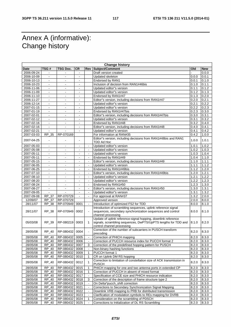
ETSI
ETSI TS 136 211 V11.5.0 (2014-01)1173GPP TS 36.211 version 11.5.0 Release 11
Annex A (informative): Change history
Change history Date TSG # TSG Doc. CR Rev Subject/Comment Old New 2006-09-24 - - - Draft version created - 0.0.0 2006-10-09 - - - Updated skeleton 0.0.0 0.0.1 2006-10-13 - - - Endorsed by RAN1 0.0.1 0.1.0 2006-10-23 - - - Inclusion of decision from RAN1#46bis 0.1.0 0.1.1 2006-11-06 - - - Updated editor"s version 0.1.1 0.1.2 2006-11-09 - - - Updated editor"s version 0.1.2 0.1.3 2006-11-10 - - - Endorsed by RAN1#47 0.1.3 0.2.0 2006-11-27 - - - Editor"s version, including decisions from RAN1#47 0.2.0 0.2.1 2006-12-14 - - - Updated editor"s version 0.2.1 0.2.2 2007-01-15 - - - Updated editor"s version 0.2.2 0.2.3 2007-01-19 - - - Endorsed by RAN1#47bis 0.2.3 0.3.0 2007-02-01 - - - Editor"s version, including decisions from RAN1#47bis 0.3.0 0.3.1 2007-02-12 - - - Updated editor"s version 0.3.1 0.3.2 2007-02-16 - - - Endorsed by RAN1#48 0.3.2 0.4.0 2007-02-16 - - - Editor"s version, including decisions from RAN1#48 0.4.0 0.4.1 2007-02-21 - - - Updated editor"s version 0.4.1 0.4.2 2007-03-03 RP_35 RP-070169 For information at RAN#35 0.4.2 1.0.0
2007-04-25 - - - Editor"s version, including decisions from RAN1#48bis and RAN1 TDD Ad Hoc 1.0.0 1.0.1
2007-05-03 - - - - Updated editor"s version 1.0.1 1.0.2 2007-05-08 - - - - Updated editor"s version 1.0.2 1.0.3 2007-05-11 - - - - Updated editor"s version 1.0.3 1.0.4 2007-05-11 - - - - Endorsed by RAN1#49 1.0.4 1.1.0 2007-05-15 - - - - Editor"s version, including decisions from RAN1#49 1.1.0 1.1.1 2007-06-05 - - - - Updated editor"s version 1.1.1 1.1.2 2007-06-25 - - - - Endorsed by RAN1#49bis 1.1.2 1.2.0 2007-07-10 - - - - Editor"s version, including decisions from RAN1#49bis 1.2.0 1.2.1 2007-08-10 - - - - Updated editor"s version 1.2.1 1.2.2 2007-08-20 - - - - Updated editor"s version 1.2.2 1.2.3 2007-08-24 - - - - Endorsed by RAN1#50 1.2.3 1.3.0 2007-08-27 - - - - Editor"s version, including decisions from RAN1#50 1.3.0 1.3.1 2007-09-05 - - - - Updated editor"s version 1.3.1 1.3.2 2007-09-08 RP_37 RP-070729 - - For approval at RAN#37 1.3.2 2.0.0
12/09/07 RP_37 RP-070729 Approved version 2.0.0 8.0.0 28/11/07 RP_38 RP-070949 0001 - Introduction of optimized FS2 for TDD 8.0.0 8.1.0
28/11/07 RP_38 RP-070949 0002 - Introduction of scrambling sequences, uplink reference signal sequences, secondary synchronization sequences and control channel processing
8.0.0 8.1.0
05/03/08 RP_39 RP-080219 0003 1 Update of uplink reference-signal hopping, downlink reference signals, scrambling sequences, DwPTS/UpPTS lengths for TDD and control channel processing
8.1.0 8.2.0
28/05/08 RP_40 RP-080432 0004 - Correction of the number of subcarriers in PUSCH transform precoding 8.2.0 8.3.0
28/05/08 RP_40 RP-080432 0005 - Correction of PHICH mapping 8.2.0 8.3.0 28/05/08 RP_40 RP-080432 0006 - Correction of PUCCH resource index for PUCCH format 2 8.2.0 8.3.0 28/05/08 RP_40 RP-080432 0007 3 Correction of the predefined hopping pattern for PUSCH 8.2.0 8.3.0 28/05/08 RP_40 RP-080432 0008 - Non-binary hashing functions 8.2.0 8.3.0 28/05/08 RP_40 RP-080432 0009 1 PUCCH format 1 8.2.0 8.3.0 28/05/08 RP_40 RP-080432 0010 1 CR on Uplink DM RS hopping 8.2.0 8.3.0
28/05/08 RP_40 RP-080432 0012 1 Correction to limitation of constellation size of ACK transmission in PUSCH 8.2.0 8.3.0
28/05/08 RP_40 RP-080432 0015 1 PHICH mapping for one and two antenna ports in extended CP 8.2.0 8.3.0 28/05/08 RP_40 RP-080432 0016 1 Correction of PUCCH in absent of mixed format 8.2.0 8.3.0 28/05/08 RP_40 RP-080432 0017 - Specification of CCE size and PHICH resource indication 8.2.0 8.3.0 28/05/08 RP_40 RP-080432 0018 3 Correction of the description of frame structure type 2 8.2.0 8.3.0 28/05/08 RP_40 RP-080432 0019 - On Delta^pucch_shift correction 8.2.0 8.3.0 28/05/08 RP_40 RP-080432 0021 - Corrections to Secondary Synchronization Signal Mapping 8.2.0 8.3.0 28/05/08 RP_40 RP-080432 0022 - Downlink VRB mapping to PRB for distributed transmission 8.2.0 8.3.0 28/05/08 RP_40 RP-080432 0023 - Clarification of modulation symbols to REs mapping for DVRB 8.2.0 8.3.0 28/05/08 RP_40 RP-080432 0024 1 Consideration on the scrambling of PDSCH 8.2.0 8.3.0 28/05/08 RP_40 RP-080432 0025 - Corrections to Initialization of DL RS Scrambling 8.2.0 8.3.0
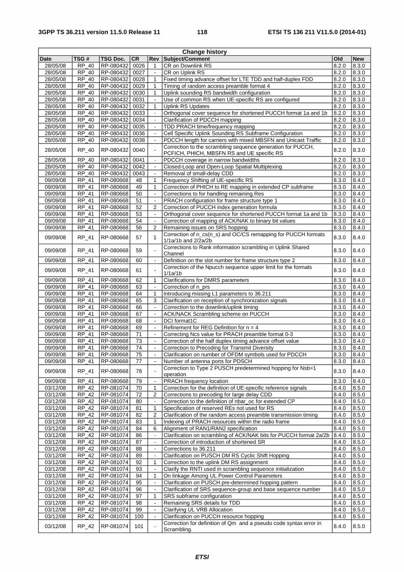
ETSI
ETSI TS 136 211 V11.5.0 (2014-01)1183GPP TS 36.211 version 11.5.0 Release 11
Change history Date TSG # TSG Doc. CR Rev Subject/Comment Old New
28/05/08 RP_40 RP-080432 0026 1 CR on Downlink RS 8.2.0 8.3.0 28/05/08 RP_40 RP-080432 0027 - CR on Uplink RS 8.2.0 8.3.0 28/05/08 RP_40 RP-080432 0028 1 Fixed timing advance offset for LTE TDD and half-duplex FDD 8.2.0 8.3.0 28/05/08 RP_40 RP-080432 0029 1 Timing of random access preamble format 4 8.2.0 8.3.0 28/05/08 RP_40 RP-080432 0030 1 Uplink sounding RS bandwidth configuration 8.2.0 8.3.0 28/05/08 RP_40 RP-080432 0031 - Use of common RS when UE-specific RS are configured 8.2.0 8.3.0 28/05/08 RP_40 RP-080432 0032 1 Uplink RS Updates 8.2.0 8.3.0 28/05/08 RP_40 RP-080432 0033 - Orthogonal cover sequence for shortened PUCCH format 1a and 1b 8.2.0 8.3.0 28/05/08 RP_40 RP-080432 0034 - Clarification of PDCCH mapping 8.2.0 8.3.0 28/05/08 RP_40 RP-080432 0035 - TDD PRACH time/frequency mapping 8.2.0 8.3.0 28/05/08 RP_40 RP-080432 0036 - Cell Specific Uplink Sounding RS Subframe Configuration 8.2.0 8.3.0 28/05/08 RP_40 RP-080432 0038 - PDCCH length for carriers with mixed MBSFN and Unicast Traffic 8.2.0 8.3.0
28/05/08 RP_40 RP-080432 0040 - Correction to the scrambling sequence generation for PUCCH, PCFICH, PHICH, MBSFN RS and UE specific RS
8.2.0 8.3.0
28/05/08 RP_40 RP-080432 0041 - PDCCH coverage in narrow bandwidths 8.2.0 8.3.0 28/05/08 RP_40 RP-080432 0042 - Closed-Loop and Open-Loop Spatial Multiplexing 8.2.0 8.3.0 28/05/08 RP_40 RP-080432 0043 - Removal of small-delay CDD 8.2.0 8.3.0 09/09/08 RP_41 RP-080668 48 1 Frequency Shifting of UE-specific RS 8.3.0 8.4.0 09/09/08 RP_41 RP-080668 49 1 Correction of PHICH to RE mapping in extended CP subframe 8.3.0 8.4.0 09/09/08 RP_41 RP-080668 50 - Corrections to for handling remaining Res 8.3.0 8.4.0 09/09/08 RP_41 RP-080668 51 - PRACH configuration for frame structure type 1 8.3.0 8.4.0 09/09/08 RP_41 RP-080668 52 2 Correction of PUCCH index generation formula 8.3.0 8.4.0 09/09/08 RP_41 RP-080668 53 - Orthogonal cover sequence for shortened PUCCH format 1a and 1b 8.3.0 8.4.0 09/09/08 RP_41 RP-080668 54 - Correction of mapping of ACK/NAK to binary bit values 8.3.0 8.4.0 09/09/08 RP_41 RP-080668 56 2 Remaining issues on SRS hopping 8.3.0 8.4.0
09/09/08 RP_41 RP-080668 57 1 Correction of n_cs(n_s) and OC/CS remapping for PUCCH formats 1/1a/1b and 2/2a/2b 8.3.0 8.4.0
09/09/08 RP_41 RP-080668 59 - Corrections to Rank information scrambling in Uplink Shared Channel
8.3.0 8.4.0
09/09/08 RP_41 RP-080668 60 - Definition on the slot number for frame structure type 2 8.3.0 8.4.0
09/09/08 RP_41 RP-080668 61 - Correction of the Npucch sequence upper limit for the formats 1/1a/1b 8.3.0 8.4.0
09/09/08 RP_41 RP-080668 62 1 Clarifications for DMRS parameters 8.3.0 8.4.0 09/09/08 RP_41 RP-080668 63 - Correction of n_prs 8.3.0 8.4.0 09/09/08 RP_41 RP-080668 64 1 Introducing missing L1 parameters to 36.211 8.3.0 8.4.0 09/09/08 RP_41 RP-080668 65 3 Clarification on reception of synchronization signals 8.3.0 8.4.0 09/09/08 RP_41 RP-080668 66 - Correction to the downlink/uplink timing 8.3.0 8.4.0 09/09/08 RP_41 RP-080668 67 - ACK/NACK Scrambling scheme on PUCCH 8.3.0 8.4.0 09/09/08 RP_41 RP-080668 68 - DCI format1C 8.3.0 8.4.0 09/09/08 RP_41 RP-080668 69 - Refinement for REG Definition for n = 4 8.3.0 8.4.0 09/09/08 RP_41 RP-080668 71 - Correcting Ncs value for PRACH preamble format 0-3 8.3.0 8.4.0 09/09/08 RP_41 RP-080668 73 - Correction of the half duplex timing advance offset value 8.3.0 8.4.0 09/09/08 RP_41 RP-080668 74 - Correction to Precoding for Transmit Diversity 8.3.0 8.4.0 09/09/08 RP_41 RP-080668 75 - Clarification on number of OFDM symbols used for PDCCH 8.3.0 8.4.0 09/09/08 RP_41 RP-080668 77 - Number of antenna ports for PDSCH 8.3.0 8.4.0
09/09/08 RP_41 RP-080668 78 - Correction to Type 2 PUSCH predetermined hopping for Nsb=1 operation
8.3.0 8.4.0
09/09/08 RP_41 RP-080668 79 - PRACH frequency location 8.3.0 8.4.0 03/12/08 RP_42 RP-081074 70 1 Correction for the definition of UE-specific reference signals 8.4.0 8.5.0 03/12/08 RP_42 RP-081074 72 2 Corrections to precoding for large delay CDD 8.4.0 8.5.0 03/12/08 RP_42 RP-081074 80 - Correction to the definition of nbar_oc for extended CP 8.4.0 8.5.0 03/12/08 RP_42 RP-081074 81 1 Specification of reserved REs not used for RS 8.4.0 8.5.0 03/12/08 RP_42 RP-081074 82 2 Clarification of the random access preamble transmission timing 8.4.0 8.5.0 03/12/08 RP_42 RP-081074 83 1 Indexing of PRACH resources within the radio frame 8.4.0 8.5.0 03/12/08 RP_42 RP-081074 84 6 Alignment of RAN1/RAN2 specification 8.4.0 8.5.0 03/12/08 RP_42 RP-081074 86 - Clarification on scrambling of ACK/NAK bits for PUCCH format 2a/2b 8.4.0 8.5.0 03/12/08 RP_42 RP-081074 87 - Correction of introduction of shortened SR 8.4.0 8.5.0 03/12/08 RP_42 RP-081074 88 - Corrections to 36.211 8.4.0 8.5.0 03/12/08 RP_42 RP-081074 89 - Clarification on PUSCH DM RS Cyclic Shift Hopping 8.4.0 8.5.0 03/12/08 RP_42 RP-081074 92 1 Correction to the uplink DM RS assignment 8.4.0 8.5.0 03/12/08 RP_42 RP-081074 93 - Clarify the RNTI used in scrambling sequence initialization 8.4.0 8.5.0 03/12/08 RP_42 RP-081074 94 1 On linkage Among UL Power Control Parameters 8.4.0 8.5.0 03/12/08 RP_42 RP-081074 95 - Clarification on PUSCH pre-determined hopping pattern 8.4.0 8.5.0 03/12/08 RP_42 RP-081074 96 - Clarification of SRS sequence-group and base sequence number 8.4.0 8.5.0 03/12/08 RP_42 RP-081074 97 1 SRS subframe configuration 8.4.0 8.5.0 03/12/08 RP_42 RP-081074 98 - Remaining SRS details for TDD 8.4.0 8.5.0 03/12/08 RP_42 RP-081074 99 - Clarifying UL VRB Allocation 8.4.0 8.5.0 03/12/08 RP_42 RP-081074 100 - Clarification on PUCCH resource hopping 8.4.0 8.5.0
03/12/08 RP_42 RP-081074 101 - Correction for definition of Qm and a pseudo code syntax error in Scrambling. 8.4.0 8.5.0
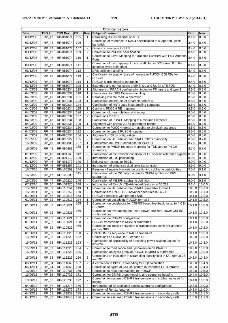
ETSI
ETSI TS 136 211 V11.5.0 (2014-01)1193GPP TS 36.211 version 11.5.0 Release 11
Change history Date TSG # TSG Doc. CR Rev Subject/Comment Old New
03/12/08 RP_42 RP-081074 105 1 Remaining Issues on SRS of TDD 8.4.0 8.5.0
03/12/08 RP_42 RP-081074 106 - Correction of reference to RAN4 specification of supported uplink bandwidth
8.4.0 8.5.0
03/12/08 RP_42 RP-081074 107 - General corrections to SRS 8.4.0 8.5.0 03/12/08 RP_42 RP-081074 109 2 Correction to PCFICH specification 8.4.0 8.5.0
03/12/08 RP_42 RP-081074 110 1 Correction to Layer Mapping for Transmit Diversity with Four Antenna Ports 8.4.0 8.5.0
03/12/08 RP_42 RP-081074 111 - Correction of the mapping of cyclic shift filed in DCI format 0 to the dynamic cyclic shift offset
8.4.0 8.5.0
03/12/08 RP_42 RP-081074 112 - DRS collision handling 8.4.0 8.5.0
03/12/08 RP_42 RP-081074 113 - Clarification to enable reuse of non-active PUCCH CQI RBs for PUSCH 8.4.0 8.5.0
03/12/08 RP_42 RP-081074 114 1 PUSCH Mirror Hopping operation 8.4.0 8.5.0 03/12/08 RP_42 RP-081074 108 1 Extended and normal cyclic prefix in DL and UL for LTE TDD 8.4.0 8.5.0 04/03/09 RP_43 RP-090234 115 1 Alignment of PRACH configuration index for FS type 1 and type 2 8.5.0 8.6.0 04/03/09 RP_43 RP-090234 118 1 Clarification for DRS Collision handling 8.5.0 8.6.0 04/03/09 RP_43 RP-090234 121 1 Removing inverse modulo operation 8.5.0 8.6.0 04/03/09 RP_43 RP-090234 123 1 Clarification on the use of preamble format 4 8.5.0 8.6.0 04/03/09 RP_43 RP-090234 124 - Clarification of RNTI used in scrambling sequence 8.5.0 8.6.0 04/03/09 RP_43 RP-090234 125 1 Clarifying PDCCH RE mapping 8.5.0 8.6.0 04/03/09 RP_43 RP-090234 126 - Correction of preamble format 4 timing 8.5.0 8.6.0 04/03/09 RP_43 RP-090234 127 2 Corrections to SRS 8.5.0 8.6.0 04/03/09 RP_43 RP-090234 128 2 Clarification of PDSCH Mapping to Resource Elements 8.5.0 8.6.0 04/03/09 RP_43 RP-090234 129 1 Alignment with correct ASN1 parameter names 8.5.0 8.6.0 04/03/09 RP_43 RP-090234 130 - Correction to PUCCH format 1 mapping to physical resources 8.5.0 8.6.0 04/03/09 RP_43 RP-090234 132 - Correction to type-2 PUSCH hopping 8.5.0 8.6.0 04/03/09 RP_43 RP-090234 134 - Alignment of SRS configuration 8.5.0 8.6.0 27/05/09 RP_44 RP-090527 135 - Correction on UE behavior for PRACH 20ms periodicity 8.6.0 8.7.0 15/09/09 RP_45 RP-090888 137 1 Clarification on DMRS sequence for PUSCH 8.7.0 8.8.0
15/09/09 RP_45 RP-090888 138 1 Correction to PHICH resource mapping for TDD and to PHICH
scrambling 8.7.0 8.8.0
01/12/09 RP_46 RP-091168 142 - Clarification of the transmit condition for UE specific reference signals 8.8.0 8.9.0 01/12/09 RP_46 RP-091172 139 2 Introduction of LTE positioning 8.9.0 9.0.0 01/12/09 RP_46 RP-091177 140 3 Editorial corrections to 36.211 8.9.0 9.0.0 01/12/09 RP_46 RP-091257 141 1 Introduction of enhanced dual layer transmission 8.9.0 9.0.0 16/03/10 RP_47 RP-100209 144 1 Removal of square brackets on positioning subframe periodicities 9.0.0 9.1.0
16/03/10 RP_47 RP-100209 145 - Clarification of the CP length of empty OFDM symbols in PRS subframes 9.0.0 9.1.0
16/03/10 RP_47 RP-100210 146 - Clarification of MBSFN subframe definition 9.0.0 9.1.0 07/12/10 RP_50 RP-101320 148 - Introduction of Rel-10 LTE-Advanced features in 36.211 9.1.0 10.0.0 15/03/11 RP_51 RP-110254 149 1 Correction on UE behavior for PRACH preamble format 4 10.0.0 10.1.0 15/03/11 RP_51 RP-110256 150 - Corrections to Rel-10 LTE-Advanced features in 36.211 10.0.0 10.1.0 01/06/11 RP_52 RP-110818 153 2 PUSCH interaction with periodic SRS 10.1.0 10.2.0 01/06/11 RP_52 RP-110819 154 1 Correction on describing PUCCH format 3 10.1.0 10.2.0
01/06/11 RP_52 RP-110821 155 3 Correction on codebooks for CSI-RS based feedback for up to 4 CSI-RS ports. 10.1.0 10.2.0
01/06/11 RP_52 RP-110821 156 - Correction on overlapping non-zero-power and zero-power CSI-RS
configurations 10.1.0 10.2.0
01/06/11 RP_52 RP-110821 157 - Correction on CSI-RS configuration 10.1.0 10.2.0 01/06/11 RP_52 RP-110821 158 - PDSCH transmission in MBSFN subframes 10.1.0 10.2.0
01/06/11 RP_52 RP-110823 159 - Correction on implicit derivation of transmission comb per antenna port for SRS 10.1.0 10.2.0
01/06/11 RP_52 RP-110823 160 - Uplink DMRS sequence in RACH procedure 10.1.0 10.2.0 15/09/11 RP_53 RP-111229 162 - Corrections on DMRS for Extended CP 10.2.0 10.3.0
15/09/11 RP_53 RP-111228 163 - Clarification of applicability of precoding power scaling factors for PDSCH
10.2.0 10.3.0
15/09/11 RP_53 RP-111228 164 - Correction to modulation and upconversion on PRACH 10.2.0 10.3.0 15/09/11 RP_53 RP-111229 165 - Clarification on cyclic prefix of PDSCH in MBSFN subframes 10.2.0 10.3.0
15/09/11 RP_53 RP-111229 166 3 Corrections on indication in scrambling identity field in DCI format 2B and 2C 10.2.0 10.3.0
05/12/11 RP_54 RP-111668 167 - A correction to PDSCH precoding for CQI calculation 10.3.0 10.4.0 05/12/11 RP_54 RP-111668 168 - Correction to figure of CSI-RS pattern in extended-CP subframe 10.3.0 10.4.0 13/06/12 RP_56 RP-120736 169 - Correction to resource mapping for PDSCH 10.4.0 10.5.0 13/06/12 RP_56 RP-120739 171 - Correction for DMRS group hopping and sequence hopping 10.4.0 10.5.0
13/06/12 RP_56 RP-120738 172 - Correction to assumed CSI-RS transmissions in subframes used for paging 10.4.0 10.5.0
04/09/12 RP_57 RP-121274 170 4 Introduction of an additional special subframe configuration 10.5.0 11.0.0 04/09/12 RP_57 RP-121272 173 - Inclusion of Rel-11 features 10.5.0 11.0.0 04/12/12 RP_58 RP-121839 175 - Correction to assumed CSI-RS transmissions in secondary cells 11.0.0 11.1.0 04/12/12 RP_58 RP-121846 176 - Correction to assumed CSI-RS transmissions in secondary cells 11.0.0 11.1.0

ETSI
ETSI TS 136 211 V11.5.0 (2014-01)1203GPP TS 36.211 version 11.5.0 Release 11
Change history Date TSG # TSG Doc. CR Rev Subject/Comment Old New
26/02/13 RP_59 RP-130254 178 - Clarification of CSI RS mapping to resource elements 11.1.0 11.2.0 26/02/13 RP_59 RP-130254 180 - Correction to CSI Reference Signals 11.1.0 11.2.0 26/02/13 RP_59 RP-130255 181 - Additional clarifications/corrections for introducing Rel-11 features 11.1.0 11.2.0 11/06/13 RP_60 RP-130752 182 - Correction to EPDCCH PRB pair indication 11.2.0 11.3.0 11/06/13 RP_60 RP-130752 183 - CR on collision between EPDCCH and PSS/SSS/PBCH 11.2.0 11.3.0 03/09/13 MCC clean-up 11.3.0 11.4.0 03/09/13 RP_60 RP-131250 185 - Correction to QCL behaviour on CRS 11.3.0 11.4.0 03/12/13 RP_62 RP-131894 186 - Correction on the derivation of the non-MBSFN region by PCFICH 11.4.0 11.5.0
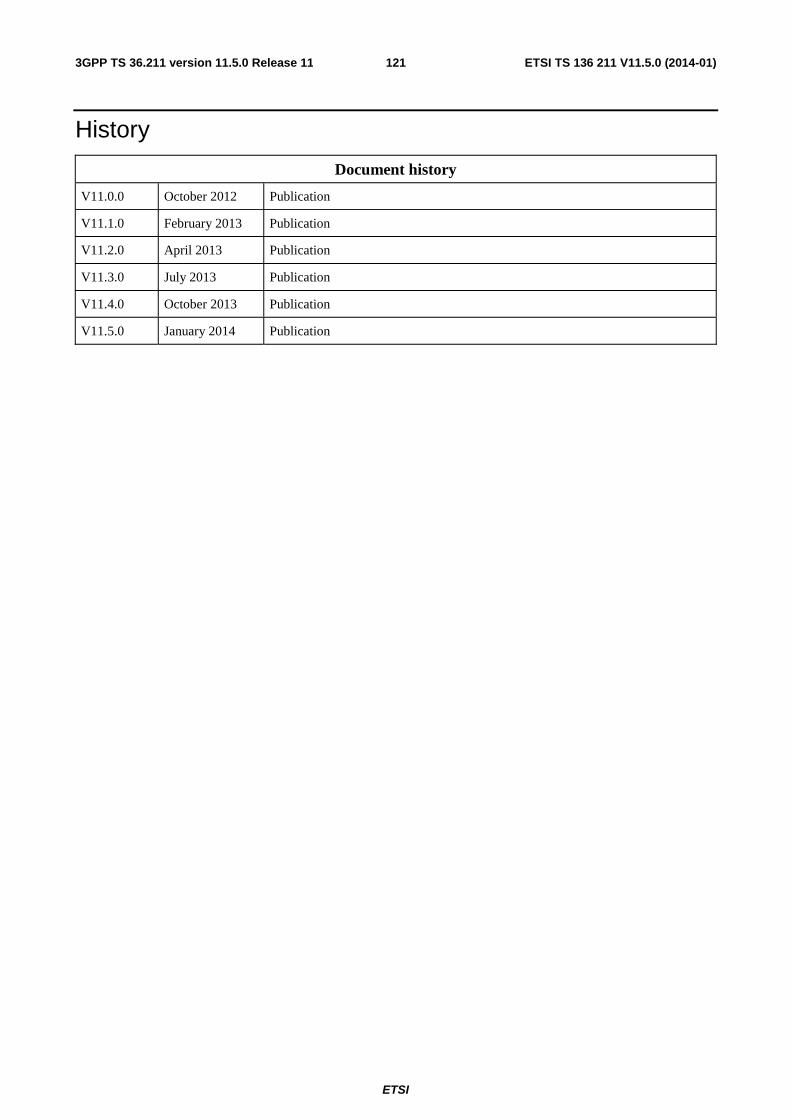
ETSI
ETSI TS 136 211 V11.5.0 (2014-01)1213GPP TS 36.211 version 11.5.0 Release 11
History
Document history
V11.0.0 October 2012 Publication
V11.1.0 February 2013 Publication
V11.2.0 April 2013 Publication
V11.3.0 July 2013 Publication
V11.4.0 October 2013 Publication
V11.5.0 January 2014 Publication