ltc 8713 series - bosch security...
TRANSCRIPT

Instruction Manual
EN Alarm Port Expanders
LTC 8713 Series

EN | 2LTC 8713 Series | Instruction Manual | Important Safeguards
Bosch Security Systems | 02 February 2004
Important Safeguards
1. Read, Follow, and Retain Instructions - All safetyand operating instructions should be read andfollowed before operating the unit. Retain instructionsfor future reference.
2. Heed Warnings - Adhere to all warnings on the unitand in the operating instructions.
3. Attachments - Attachments not recommended by theproduct manufacturer should not be used, as theymay cause hazards.
4. Installation Cautions - Do not place this unit on anunstable stand, tripod, bracket, or mount. The unitmay fall, causing serious injury to a person andserious damage to the unit. Use only manufacturer-recommended accessories, or those sold with theproduct. Mount the unit per the manufacturer'sinstructions. Appliance and cart combination shouldbe moved with care. Quick stops, excessive force, oruneven surfaces may cause the appliance and cartcombination to overturn.
5. Cleaning - Unplug the unit from the outlet beforecleaning. Follow any instructions provided with theunit. Generally, using a damp cloth for cleaning issufficient. Do not use liquid cleaners or aerosolcleaners.
6. Servicing - Do not attempt to service this unityourself. Opening or removing covers may exposeyou to dangerous voltage or other hazards. Refer allservicing to qualified service personnel.
7. Damage Requiring Service - Unplug the unit fromthe main AC power source and refer servicing toqualified service personnel under the followingconditions:• When the power supply cord or plug is damaged.• If liquid has been spilled or an object has fallen
into the unit.• If the unit has been exposed to water and/or
inclement weather (rain, snow, etc.).• If the unit does not operate normally, when
following the operating instructions. Adjust onlythose controls specified in the operatinginstructions. Improper adjustment of other controlsmay result in damage, and require extensive workby a qualified technician to restore the unit tonormal operation.
• If the unit has been dropped or the cabinetdamaged.
• If the unit exhibits a distinct change inperformance, this indicates that service is needed.
8. Replacement Parts - When replacement parts arerequired, the service technician should usereplacement parts specified by the manufacturer orthat have the same characteristics as the original part.Unauthorized substitutions may result in fire,electrical shock or other hazards.
9. Safety Check - Upon completion of servicing orrepairs to the unit, ask the service technician toperform safety checks to ensure proper operatingcondition.
10. Power Sources - Operate the unit only from the typeof power source indicated on the label. If unsure ofthe type of power supply to use, contact your dealeror local power company. • For units intended to operate from battery power,
refer to the operating instructions. • For units intended to operate with External Power
Supplies, use only the recommended approvedpower supplies.
• For units intended to operate with a limited powersource, this power source must comply withEN60950. Substitutions may damage the unit orcause fire or shock.
• For units intended to operate at 24VAC, normalinput voltage is 24VAC. Voltage applied to theunit's power input should not exceed 30VAC. User-supplied wiring, from the 24VAC supply tounit, must be in compliance with electrical codes(Class 2 power levels). Do not ground the 24VACsupply at the terminals or at the unit's powersupply terminals.
11. Coax Grounding - If an outside cable system isconnected to the unit, ensure that the cable system isgrounded. U.S.A. models only - Section 810 of theNational Electrical Code, ANSI/NFPA No.70,provides information regarding proper grounding ofthe mount and supporting structure, grounding of thecoax to a discharge unit, size of groundingconductors, location of discharge unit, connection togrounding electrodes, and requirements for thegrounding electrode.
12. Grounding or Polarization - This unit may beequipped with a polarized alternating current lineplug (a plug with one blade wider than the other).This safety feature allows the plug to fit into thepower outlet in only one way. If unable to insert theplug fully into the outlet, try reversing the plug. If theplug still fails to fit, contact an electrician to arrangereplacement of the obsolete outlet. Do not defeat thesafety purpose of the polarized plug.Alternately, this unit may be equipped with a 3-wire grounding plug (a plug with a third pin, forgrounding). This safety feature allows the plug to fitinto a grounding power outlet only. If unable to insertthe plug into the outlet, contact an electrician toarrange replacement of the obsolete outlet. Do notdefeat the safety purpose of the grounding plug.
13. Lightning - For added protection during a lightningstorm, or when this unit is left unattended and unusedfor long periods of time, unplug the unit from thewall outlet and disconnect the cable system. This willprevent damage to the unit due to lightning andpower line surges.

EN | 3LTC 8713 Series | Instruction Manual | Safety Precautions
Bosch Security Systems | 02 February 2004
For Indoor Product1. Water and Moisture - Do not use this unit near
water - for example, in a wet basement, in anunprotected outdoor installation or in any areaclassified as a wet location.
2. Object and Liquid Entry - Never push objects ofany kind into this unit through openings, as theymay touch dangerous voltage points or short outparts that could result in a fire or electrical shock.Never spill liquid of any kind on the unit.
3. Power Cord and Power Cord Protection - Forunits intended to operate with 230VAC, 50Hz,the input and output power cord must complywith the latest versions of IEC Publication 227 orIEC Publication 245. Power supply cords should be routed so they arenot likely to be walked on or pinched. Payparticular attention to location of cords and plugs,convenience receptacles, and the point of exitfrom the appliance.
4. Overloading - Do not overload outlets andextension cords; this can result in a risk of fire orelectrical shock.
For Outdoor ProductPower Lines - An outdoor system should not belocated in the vicinity of overhead power lines,electric lights or power circuits, or where it maycontact such power lines or circuits. Wheninstalling an outdoor system, extreme care shouldbe taken to keep from touching power lines orcircuits, as this contact might be fatal. U.S.A.models only - refer to the National ElectricalCode Article 820 regarding installation of CATVsystems.
For Rack-mount Product1. Ventilation - This unit should not be placed in a
built-in installation or rack, unless properventilation is provided, or the manufacturer’sinstructions have been adhered to. Theequipment must not exceed its maximumoperating temperature requirements.
2. Mechanical Loading - Mounting of theequipment in a rack shall be such that ahazardous condition is not achieved due touneven mechanical loading.
Safety Precautions
Attention: Installation should be performed byqualified service personnel only in accordancewith the National Electrical Code or applicablelocal codes.
Power Disconnect. Units with or without ON-OFF switches have power supplied to theunit whenever the power cord is inserted into thepower source; however, the unit is operationalonly when the ON-OFF switch is in the ONposition. The power cord is the main powerdisconnect for all units.
CAUTION: TO REDUCE THE RISK OFELECTRIC SHOCK, DO NOT REMOVE COVER(OR BACK). NO USER SERVICEABLE PARTSINSIDE. REFER SERVICING TO QUALIFIEDSERVICE PERSONNEL.
This symbol indicates the presence ofuninsulated “dangerous voltage” within theproduct’s enclosure. This may constitute arisk of electric shock.
The user should consult the operating andmaintenance (servicing) instructions in theliterature accompanying the appliance.

LTC 8713 Series | Instruction Manual | FCC & ICES Information EN | 4
Bosch Security Systems | 02 February 2004
Sécurité
Attention : l'installation doit exclusivement être réalisée par dupersonnel qualifié, conformément au code national d'électricitéaméricain (NEC) ou au code d'électricité local en vigueur.
Coupure de l'alimentation. Qu'ils soient pourvus ou non d'uncommutateur ON/OFF, tous les appareils reçoivent de l'énergie unefois le cordon branché sur la source d'alimentation. Toutefois,l'appareil ne fonctionne réellement que lorsque le commutateur est réglé sur ON. Le débranchement du cordond'alimentation permet de couper l'alimentation des appareils.
ATTENTION : POUR ÉVITER TOUT RISQUE D'ÉLECTROCUTION,
N'ESSAYEZ PAS DE RETIRER LE CAPOT (OU LE PANNEAU
ARRIÈRE). CET APPAREIL NE CONTIENT AUCUN COMPOSANT
SUSCEPTIBLE D'ÊTRE RÉPARÉ PAR L'UTILISATEUR. CONFIEZ
LA RÉPARATION DE L'APPAREIL À DU PERSONNEL QUALIFIÉ.
Ce symbole signale que le produit renferme une « tensionpotentiellement dangereuse » non isolée susceptible deprovoquer une électrocution.
Ce symbole invite l'utilisateur à consulter les instructionsd'utilisation et d'entretien (dépannage) reprises dans ladocumentation qui accompagne l'appareil.
Sicherheitshinweise
Achtung! Die Installation sollte nur von qualifiziertemKundendienstpersonal gemäß jeweils zutreffenderElektrovorschriften ausgeführt werden.
Unterbrechung des Netzanschlusses. Geräte mit oder ohneNetzschalter haben Spannung am Gerät anliegen, sobald derNetzstecker in die Steckdose gesteckt wird. Das Gerät ist jedochnur betriebsbereit, wenn der Netzschalter (EIN/AUS) auf EINsteht. Wenn das Netzkabel aus der Steckdose gezogen wird, istdie Spannungszuführung zum Gerät vollkommen unterbrochen.
VORSICHT: UM EINEN ELEKTRISCHEN SCHLAG ZU
VERMEIDEN, IST DIE ABDECKUNG (ODER RÜCKSEITE) NICHT
ZU ENTFERNEN. ES BEFINDEN SICH KEINE TEILE IN DIESEM
BEREICH, DIE VOM BENUTZER GEWARTET WERDEN
KÖNNEN. LASSEN SIE WARTUNGSARBEITEN NUR VON
QUALIFIZIERTEM WARTUNGSPERSONAL AUSFÜHREN.
Das Symbol macht auf nicht isolierte „gefährliche Spannung"im Gehäuse aufmerksam. Dies kann zu einem elektrischenSchlag führen.
Der Benutzer sollte sich ausführlich über Anweisungen fürdie Bedienung und Instandhaltung (Wartung) in denbegleitenden Unterlagen informieren.
Precauciones de Seguridad
Atención: la instalación la debe realizar únicamente personalcualificado de conformidad con el National Electric Code o lasnormas aplicables en su país.
Desconexión de la alimentación. Las unidades con o sininterruptores de encendido/apagado reciben alimentacióneléctrica siempre que el cable de alimentación esté conectado ala fuente de alimentación. Sin embargo, la unidad sólo funcionacuando el interruptor está en la posición de encendido. El cablede alimentación es la principal fuente de desconexión de todaslas unidades.
PRECAUCIÓN: PARA DISMINUIR EL RIESGO DE DESCARGAELÉCTRICA, NO RETIRE LA CUBIERTA (NI LA PARTEPOSTERIOR). NO EXISTEN PIEZAS DE RECAMBIO EN ELINTERIOR DEL EQUIPO. EL PERSONAL DE SERVICIOCUALIFICADO SE ENCARGA DE REALIZAR LASREPARACIONES.
Este símbolo indica que existen puntos de tensión peligrosossin aislamiento dentro de la cubierta de la unidad. Estospuntos pueden constituir un riesgo de descarga eléctrica.
El usuario debe consultar las instrucciones de funcionamiento ymantenimiento (reparación) en la documentación que sesuministra con el aparato.
FCC & ICES INFORMATION(U.S.A. and Canadian Models Only)This device complies with part 15 of the FCC Rules. Operation issubject to the following two conditions:
(1) This device may not cause harmful interference, and(2) This device must accept any interference received,
including interference that may cause undesiredoperation.
NOTE: This equipment has been tested and found to complywith the limits for a Class B digital device, pursuant to Part 15 ofthe FCC Rules and ICES-003 of Industry Canada. These limitsare designed to provide reasonable protection against harmfulinterference when the equipment is operated in a residentialinstallation. This equipment generates, uses and can radiate radiofrequency energy, and if not installed and used in accordancewith the instructions, may cause harmful interference to radiocommunications. However, there is no guarantee that interferencewill not occur in a particular installation. If this equipment doescause harmful interference to radio or television reception, whichcan be determined by turning the equipment off and on, the useris encouraged to try to correct the interference by one or more of the following measures:
• Reorient or relocate the receiving antenna.• Increase the separation between the equipment and receiver.• Connect the equipment into an outlet on a circuit different
from that to which the receiver is connected.• Consult the dealer, or an experienced radio/TV technician for
help.Intentional or unintentional changes or modifications, notexpressly approved by the party responsible for compliance, shallnot be made. Any such changes or modifications could void theuser’s authority to operate the equipment.The user may find thefollowing booklet, prepared by the Federal CommunicationsCommission, helpful: How to Identify and Resolve Radio-TVInterference Problems. This booklet is available from the U.S.Government Printing Office, Washington, DC 20402, Stock No.004-000-00345-4.

EN | 5LTC 8713 Series | Instruction Manual | Safety Precautions
Bosch Security Systems | 02 February 2004
Veiligheidsmaatregelen
Attentie: het apparaat mag alleen door gekwalificeerd personeelworden geïnstalleerd. De installatie dient in overeenstemmingmet de nationale elektrische richtlijnen of de van toepassingzijnde lokale richtlijnen te worden uitgevoerd.
Spanning uitschakelen. Apparatuur met of zonder aan-uitschakelaar staat onder spanning zolang de stekker isaangesloten op de wandcontactdoos. De apparatuur is uitsluitendin werking als de aan-uitschakelaar aan staat. Het netsnoer is de"hoofdschakelaar" voor alle apparatuur.
VOORZICHTIG: OPEN DE BEHUIZING OF DE ACHTERKANTVAN HET APPARAAT NIET. ZO VERMINDERT U HET RISICOOP ELEKTRISCHE SCHOKKEN. IN HET APPARAATBEVINDEN ZICH GEEN ONDERDELEN DIE U ZELF KUNTREPAREREN. LAAT SERVICE EN ONDERHOUD UITVOERENDOOR GEKWALIFICEERD PERSONEEL.
Dit symbool geeft aan dat er binnen in het apparaatongeïsoleerde, gevaarlijke spanning aanwezig is die mogelijkelektrische schokken kan veroorzaken.
De gebruiker dient de bedienings- en onderhoudsvoorschriftente raadplegen in de documentatie die werd meegeleverd methet apparaat.
Sicurezza
Attenzione: l'installazione deve essere effettuata esclusivamenteda personale tecnico qualificato in conformità con il NationalElectrical Code o con le normative locali vigenti.
Scollegamento dell'alimentazione. Le unità dotate o sprovviste diinterruttori ON-OFF vengono alimentate quando si inserisce ilcavo nella presa dell'alimentazione. L'unità è tuttavia in funzionesolo quando l'interruttore ON-OFF si trova nella posizione ON. Ilcavo di alimentazione costituisce il dispositivo di scollegamentodell'alimentazione principale per tutte le unità.
ATTENZIONE: PER RIDURRE IL RISCHIO DI SCOSSEELETTRICHE NON RIMUOVERE LA COPERTURA (O ILPANNELLO POSTERIORE). L'UNITÀ NON CONTIENECOMPONENTI INTERNI RIPARABILI DALL'UTENTE. PERQUALSIASI INTERVENTO, RIVOLGERSI A PERSONALETECNICO QUALIFICATO.
Questo simbolo indica la presenza di "tensione pericolosa" nonisolata all'interno del contenitore del prodotto. Ciò comporta unpotenziale rischio di scosse elettriche.
Si consiglia di consultare le istruzioni operative e dimanutenzione (interventi tecnici) contenute nelladocumentazione fornita con il dispositivo.
Medidas de Segurança
Atenção: a instalação deve ser executada apenas por técnicosqualificados da assistência, de acordo com o código eléctriconacional ou os códigos locais aplicáveis.
Corte de corrente. As unidades com ou sem interruptores ON-OFF (ligar/desligar) recebem corrente sempre que o fio dealimentação está introduzido na fonte de alimentação; contudo, aunidade apenas está operacional quando o interruptor ON-OFFestá na posição ON. O fio de alimentação destina-se a desligar acorrente em todas as unidades.
CUIDADO: PARA REDUZIR O RISCO DE CHOQUE
ELÉCTRICO, NÃO RETIRE A TAMPA (OU A PARTE
POSTERIOR). NO INTERIOR, NÃO EXISTEM PEÇAS QUE
POSSAM SER REPARADAS PELO UTILIZADOR. REMETA A
ASSISTÊNCIA PARA OS TÉCNICOS QUALIFICADOS.
Este símbolo indica a presença de "tensão perigosa" não isoladadentro da estrutura do produto, o que pode constituir risco dechoque eléctrico.
O utilizador deve consultar as instruções de funcionamentoe manutenção (assistência) nos documentos queacompanham o aparelho.
Zasady Bezpieczeństwa
Uwaga: Instalacja może być wykonywana wyłącznie przezwykwalifikowanych pracowników obsługi, zgodnie z zasadamikodeksu National Electrical Code lub innych obowiązującychnorm.
Odłączanie zasilania Niezależnie od wyposażenia w wyłącznikzasilania, prąd do urządzenia jest doprowadzany zawsze, gdyprzewód zasilania jest podłączony do źródła zasilania; jednakurządzenie działa tylko wtedy, gdy wyłącznik zasilania jestwłączony. Przewód zasilania jest głównym wyłącznikiem zasilaniawe wszystkich urządzeniach.
PRZESTROGA: ABY ZMNIEJSZYĆ RYZYKO PORAŻENIA
ELEKTRYCZNEGO, NIE NALEŻY ZDEJMOWAĆ POKRYWY
GÓRNEJ (ani tylnej). WEWNĄTRZ URZĄDZENIA NIE MA
ŻADNYCH ELEMENTÓW, KTÓRE MOGĄ BYĆ NAPRAWIANE
SAMODZIELNIE PRZEZ UŻYTKOWNIKA. SERWIS NALEŻY
ZLECAĆ WYKWALIFIKOWANYM PRACOWNIKOM OBSŁUGI.
Ten symbol wskazuje na obecność nieizolowanego„niebezpiecznego napięcia” we wnętrzu urządzenia. Napięcieto grozi porażeniem elektrycznym.
Użytkownik powinien zapoznać się z instrukcjami obsługi ikonserwacji (serwisu), zamieszczonymi w dokumentacjitowarzyszącej urządzeniu.

EN | 6
Table of ContentsImportant Safeguards . . . . . . . . . . . . . . . . . . . . . . . . . . . . . . . . . . . . . . . . . . . . . . . . . . . . . . . . . . . . . . . . . .2FCC & ICES Information . . . . . . . . . . . . . . . . . . . . . . . . . . . . . . . . . . . . . . . . . . . . . . . . . . . . . . . . . . . . . .41 UNPACKING . . . . . . . . . . . . . . . . . . . . . . . . . . . . . . . . . . . . . . . . . . . . . . . . . . . . . . . . . . . . . . . . . .72 SERVICE . . . . . . . . . . . . . . . . . . . . . . . . . . . . . . . . . . . . . . . . . . . . . . . . . . . . . . . . . . . . . . . . . . . . .73 DESCRIPTION . . . . . . . . . . . . . . . . . . . . . . . . . . . . . . . . . . . . . . . . . . . . . . . . . . . . . . . . . . . . . . . .73.1 Alarm Capacities . . . . . . . . . . . . . . . . . . . . . . . . . . . . . . . . . . . . . . . . . . . . . . . . . . . . . . . . . . . . . . . .74 INSTALLATION . . . . . . . . . . . . . . . . . . . . . . . . . . . . . . . . . . . . . . . . . . . . . . . . . . . . . . . . . . . . . . .84.1 Power . . . . . . . . . . . . . . . . . . . . . . . . . . . . . . . . . . . . . . . . . . . . . . . . . . . . . . . . . . . . . . . . . . . . . . . . .84.2 Mounting . . . . . . . . . . . . . . . . . . . . . . . . . . . . . . . . . . . . . . . . . . . . . . . . . . . . . . . . . . . . . . . . . . . . . .84.3 Cover Removal . . . . . . . . . . . . . . . . . . . . . . . . . . . . . . . . . . . . . . . . . . . . . . . . . . . . . . . . . . . . . . . . .84.4 DIP Switch Settings . . . . . . . . . . . . . . . . . . . . . . . . . . . . . . . . . . . . . . . . . . . . . . . . . . . . . . . . . . . . . .95 OPERATION . . . . . . . . . . . . . . . . . . . . . . . . . . . . . . . . . . . . . . . . . . . . . . . . . . . . . . . . . . . . . . . . .106 ILLLUSTRATIONS . . . . . . . . . . . . . . . . . . . . . . . . . . . . . . . . . . . . . . . . . . . . . . . . . . . . . . . . . . . .11
LTC 8713 Series | Instruction Manual | Table of Contents
Bosch Security Systems | 02 February 2004

EN | 7
Bosch Security Systems | 02 February 2004
LTC 8713 Series | Instruction Manual | Unpacking
1 UNPACKINGUnpack carefully. This is electronic equipment andshould be handled carefully.
Check for the following items:
• Verify the unit model number.
• One (1) cable assembly with 9-pin D-subconnectors.
If an item appears to have been damaged in shipment,replace it properly in its carton and notify the shipper.If any items are missing, notify your Bosch SecuritySystems, Inc. Sales Representative or CustomerService.
The shipping carton is the safest container in which theunit may be transported. Save it for possible future use.
2 SERVICEIf the unit ever needs repair service, the customershould contact the nearest Bosch Security Systems, Inc.Service Center for authorization to return and shippinginstructions.
Service CentersUSA: Phone: 800-366-2283 or 717-735-6638
fax: 800-366-1329 or 717-735-6639CCTV Spare Parts
Phone: 800-894-5215 or 408-956-3853 or 3854fax: 408-957-3198
e-Mail: [email protected]: 514-738-2434Europe, Middle East & Asia Pacific Region:
32-1-440-0711
For additional information, seewww.boschsecuritysystems.com.
NOTE: Grounded wrist straps must be worn andproper ESD safety precautions observed whenhandling the electrostatic-sensitive printed circuitboards.
3 DESCRIPTIONThe LTC 8713 Series Alarm Port Expanders are used tointerface multiple LTC 8540/00 Alarm Interface Unitswith an the Allegiant® series matrix switcher/controllersystem.
A single LTC 8713 Series Alarm Port Expandersupports up to four LTC 8540/00 Alarm InterfaceUnits. This provides the capability for up to 256 alarminput points. Multiple LTC 8713 units may becombined to provide up to 1024 alarm input pointsusing up to sixteen LTC 8540/00 units. The actualnumber of units that can be used in a system dependsupon the model of the Allegiant system being used.See Alarm Capacities table listing maximum number ofLTC 8713 series units and LTC 8540/00 units that canbe used with each Allegiant series system model.
3.1 Alarm CapacitiesAllegiant Maximum Maximum MaximumSystem Number of Number of Number ofModel1 Alarms LTC 8713 LTC 8540/00LTC 8500 128 1 2LTC 8600 512 3 8LTC 8800 1024 5 16LTC 8900 1024 5 16
1The capacities shown apply to Allegiant CPU modules containing software revision 7.1 or later.
WARNING: Electrostatic-sensitivedevice. Use proper CMOS/MOSFET handling precautions toavoid electrostatic discharge.
ATTENTIONOBSERVE PRECAUTIONS
FOR HANDLINGELECTROSTATIC
SENSITIVEDEVICES

EN | 8
Bosch Security Systems | 02 February 2004
LTC 8713 Series | Instruction Manual | Installation
For each LTC 8540/00 unit used in an "alarmexpanded configuration", one 12 VDC to 15 VDC, 5 W power supply1 (not included) is required.
Each LTC 8540/00 unit is supplied with a singleinterface cable. This cable is used to connect a singleLTC 8540/00 unit to one of the four expansion portson the LTC 8713 Series Alarm Port Expander. Thecable supplied with the LTC 8713 Series Alarm PortExpander must be used to connect the "SYSTEM"port on the LTC 8713 series unit to the "ALARM" porton the Allegiant series system. In certain configurations,the cable from one LTC 8713 series unit can beconnected to an expansion port of a second LTC 8713series unit that is being used as an "alarm expanderhub". See typical applications underILLUSTRATIONS.
1A TC120PS power supply may be used for 120 VAC, 50/60 Hz operation or a TC220PS power supply for 220-240 VAC, 50/60 Hz operation.
4 INSTALLATION4.1 PowerModel No. Rated Voltage Nominal
Voltage1 Range Power2
LTC 8713/60 120 VAC, 105 to 130 10 W50/60 Hz
LTC 8713/50 220-240 VAC, 198 to 264 10 W50/60 Hz
1The model number and operating voltage are shown on the bottom of the unit. These units are supplied with grounded power cords; grounding must not be defeated.
2At rated voltage.
4.2 MountingThese units are supplied as desk top units. For rackmounting, the LTC 9101/00 rack-mount kit is available.These units are half-rack units.
4.3 Cover RemovalRemoval of the cover and adjustment ofinternal controls should only be performedby qualified service personnel – not userserviceable. The unit should always beunplugged before removing the cover andremain unplugged while the cover isremoved.
The cover is fastened to the chassis by two screws onthe bottom near the rear of the unit. Disassembly is asshown.
Figure 1 Cover Removal
Slide Cover Back
Remove Screws FromBottom Rear Corners(2) Places
EN | 9
Bosch Security Systems | 02 February 2004
LTC 8713 Series | Instruction Manual | Installation
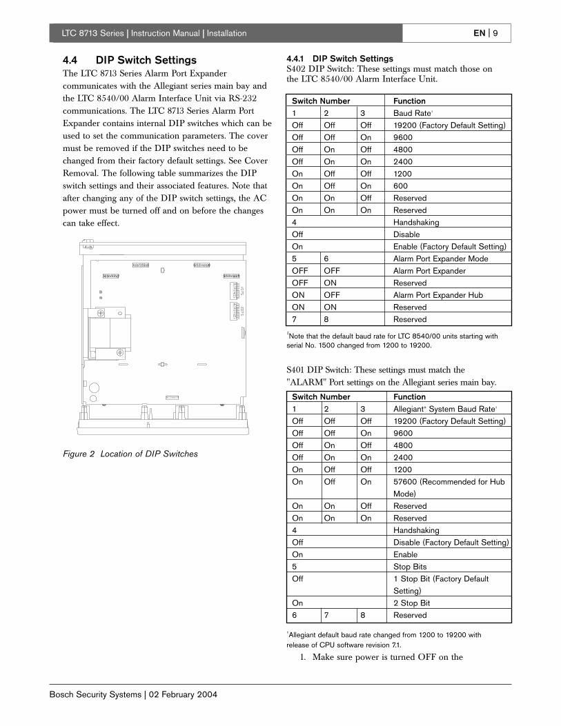
4.4 DIP Switch SettingsThe LTC 8713 Series Alarm Port Expandercommunicates with the Allegiant series main bay andthe LTC 8540/00 Alarm Interface Unit via RS-232communications. The LTC 8713 Series Alarm PortExpander contains internal DIP switches which can beused to set the communication parameters. The covermust be removed if the DIP switches need to bechanged from their factory default settings. See CoverRemoval. The following table summarizes the DIPswitch settings and their associated features. Note thatafter changing any of the DIP switch settings, the ACpower must be turned off and on before the changescan take effect.
Figure 2 Location of DIP Switches
4.4.1 DIP Switch SettingsS402 DIP Switch: These settings must match those onthe LTC 8540/00 Alarm Interface Unit.
1Note that the default baud rate for LTC 8540/00 units starting withserial No. 1500 changed from 1200 to 19200.
S401 DIP Switch: These settings must match the"ALARM" Port settings on the Allegiant series main bay.
1Allegiant default baud rate changed from 1200 to 19200 withrelease of CPU software revision 7.1.
1. Make sure power is turned OFF on the
Switch Number Function1 2 3 Baud Rate1
Off Off Off 19200 (Factory Default Setting)Off Off On 9600Off On Off 4800Off On On 2400On Off Off 1200On Off On 600On On Off ReservedOn On On Reserved4 HandshakingOff DisableOn Enable (Factory Default Setting)5 6 Alarm Port Expander ModeOFF OFF Alarm Port ExpanderOFF ON ReservedON OFF Alarm Port Expander HubON ON Reserved7 8 Reserved
Switch Number Function1 2 3 Allegiant® System Baud Rate1
Off Off Off 19200 (Factory Default Setting)Off Off On 9600Off On Off 4800Off On On 2400On Off Off 1200On Off On 57600 (Recommended for Hub
Mode)On On Off ReservedOn On On Reserved4 HandshakingOff Disable (Factory Default Setting)On Enable5 Stop BitsOff 1 Stop Bit (Factory Default
Setting)On 2 Stop Bit6 7 8 Reserved

EN | 10
Bosch Security Systems | 02 February 2004
LTC 8713 Series | Instruction Manual | Operation
Allegiant series main bay and the LTC 8713Series Alarm Port Expander. Make sure that the external power supply used to power theLTC 8540/00 Alarm Interface unit is notconnected to a wall outlet.
2. Using the cable supplied with the LTC 8540/00Alarm Interface Unit, connect one end of thecable to "PORT 1" on the rear of LTC 8713Series Alarm Port Expander. Connect the otherend of the cable to the "RS-232" port on theLTC 8540/00.
3. Similarly, repeat step 2 for each LTC 8540/00Alarm Interface Unit.
4. Using the cable supplied with the LTC 8713Series Alarm Port Expander, connect one endof the cable to the connector marked"SYSTEM" on the LTC 8713 Series. Connectthe other end of the cable to the connectormarked "ALARM" on the Allegiant seriessystem.
In this configuration, 256 alarms can beconfigured using one LTC 8713 series unit andfour LTC 8540/00 units. A LTC 8713,configured as an alarm port expander hub, maybe used to extend the number of alarms to1024. The LTC 8713 Series units can beconfigured as an alarm port expander hub viaDIP switches S402-5 and S402-6. See TypicalLTC 8713 Series Alarm Port ExpanderApplication For More Than 256 Alarms underILLUSTRATIONS. Note that when using theLTC 8713 as an alarm port expander hub, thebaud rate must be set to 57600 via DIP switchesS401-1 through S401-3. Refer to the applicableAllegiant system installation instructions toconfigure its alarm port to the 57600 baud rate.
5 OPERATION1. Connect the external power to the LTC 8540/00
Alarm Interface Units. The power LED on theLTC 8540/00 Alarm Interface Units should beon.
2. Turn on the Allegiant Series main bay and theLTC 8713 Series Alarm Port Expander. Thepower LED on the LTC 8713 Series unit shouldbe on.
3. Note that the system Tx LEDs on the frontpanel of the LTC 8713 Series indicate wheneveralarm data is being sent to the Allegiant seriesunit from the LTC 8713 Series. The system Rx LEDs indicate when alarm data is beingreceived from the Allegiant series unit. Thisdata consists of "alarm verification" and "relayaction" data. Both types of data are sent to theLTC 8713 unit immediately after the Allegiantseries unit receives alarm data. This data willalso be sent back and forth on an occasionalbasis to maintain current system status.
4. The "alarm" port Rx LEDs will indicate whenalarm data is being received from thecorresponding LTC 8540 Series Alarm InterfaceUnit. The "alarm" port Tx LEDs indicate that"alarm verification" data and "relay action" datais being sent to the respective LTC 8540/00unit. This data will also be sent back and forthon an occasional basis to maintain currentsystem status.

EN | 11
Bosch Security Systems | 02 February 2004
LTC 8713 Series | Instruction Manual | Illustrations
6 ILLUSTRATIONS
Ports 1 Through 4 - Female 9-pin D-Sub Connector
Pin Function1 RTS2 Tx (Transmit)3 Chassis Ground4 Data Ground5 Data Ground6 Rx (Receive)7 CTS8 NC (No Connection)9 NC (No Connection)
Pin Function1 Chassis Ground2 Rx (Receive)3 Tx (Transmit)4 CTS5 RTS6 Data Ground7 Data Ground8 NC (No Connection)9 NC (No Connection)
System Port - Male 9-pin D-Sub Connector
Figure 3 LTC 8713 Series - Front and Back Panels
12345
6789
S9502017AE
1 2 3 4 5
6 7 8 9
S9502018AE

EN | 12
Bosch Security Systems | 02 February 2004
LTC 8713 Series | Instruction Manual | Illustrations
Alarm Port
Cable Supplied withLTC 8713 SeriesAlarm Port Expanders
LTC 8713 SeriesAlarm Port Expanders (Rear View)
Cables Supplied with LTC 8540/00Alarm Interface Unit
Power Supply(See Note)
LTC 8540/00 Alarm Interface Units (Rear View) Alarm Inputs 1 to 64
Alarm Inputs 65 to128
Alarm Inputs 129 to 192 (LTC 8800 Series System Only)
Alarm Inputs 193 to 256 (LTC 8800 Series System Only)
Note: The power supplies shown are not included.TC120PS is required for 120 VAC, 50/60 Hz operation;TC220PS is required for 220-240 VAC, 50/60 Hz operation.
9 PinD-Connector
9 PinD-Connector
9 PinD-Connector
9 PinD-Connector
LTC 8600 Series or LTC 8800 Series Allegiant Series MainBay (Rear View)
(See Note)
(See Note)
(See Note)
Figure 4 Typical LTC 8713 Series Alarm Port Expander Application for up to 256 Alarms

EN | 13
Bosch Security Systems | 02 February 2004
LTC 8713 Series | Instruction Manual | Illustrations
Alarm Port
Cable Supplied withLTC 8713 SeriesAlarm Port Expanders
LTC 8713 SeriesAlarm Port Expander Hub (Rear View)
Cables Supplied withLTC 8713 Alarm Expander Units
LTC 8600 Series or LTC 8800 Series Allegiant Series Main Bay (Rear View)
Ports 1, 2, 3, and 4 of LTC 8713 SeriesAlarm Port Expander to Four LTC 8540/00Alarm Interface Units (Alarms 769-1024)
Ports 1, 2, 3, and 4 of LTC 8713 SeriesAlarm Port Expander to Four LTC 8540/00Alarm Interface Units (Alarms 513 to 768)
Ports 1, 2, 3, and 4 of LTC 8713 SeriesAlarm Port Expander to Four LTC 8540/00Alarm Interface Units (Alarms 257 to 512)
Ports 1, 2, 3, and 4 of LTC 8713 SeriesAlarm Port Expander to Four LTC 8540/00Alarm Interface Units (Alarms 1 to 256)
Figure 5 Typical LTC 8713 Series Alarm Port Expander Application for more than 256 Alarms

LTC 8713 Series | Instruction Manual | EN | 14
Bosch Security Systems | 02 February 2004

LTC 8713 Series | Instruction Manual | EN | 15
Bosch Security Systems | 02 February 2004

© 2004 Bosch Security Systems GmbH
3935 890 04712 04-06 | February 04, 2004 | Data subject to change without notice.
Bosch Security Systems, Inc.850 Greenfield Road Lancaster, PA 17601 USATel: 800-326-3270Fax: 1-717-735-6560www.boschsecuritysystems.com
Bosch Security Systems B.V.P.O. Box 800025600 JB EindhovenThe NetherlandsTele +31 40 27 80000
Bosch Security Systems Pte Ltd.38C Jalan PemimpinSingapore 577180Republic of SingaporeTel: 65 (6) 319 3486