lsi pole vibration application guidelines
TRANSCRIPT

LSI Industries Inc. 10000 Alliance Rd. Cincinnati, OH 45242 • www.lsicorp.com(513) 372-3200 • ©2020 LSI Industries Inc. All Rights Reserved. Specifications subject to change without notice.
Page 1/6 Rev. 10/02/20 WHTP.1075.A.0920
DEFINITIONS
First Mode Vibration (Harmonic)
First mode vibration, also known as harmonic vibration, is characterized by the side to side motion of a pole and typically referred to as “sway”. High velocity gusts of wind cause the greatest displacement at the top of the pole moving at a frequency of about 1 cycle per second. First Mode vibration is generally not harmful to the pole or luminaire.
Second Mode Vibration (Resonance)
Second mode vibration, also known as resonance vibration, is characterized by the symmetric oscillation that occurs when the wind synchronizes with the pole’s natural frequency. Second mode vibration occurs near the midpoint of the pole and can cause the material fatigue related to pole failure. The typical frequency of movement is about 3 to 6 cycles per second.
Vortex Shedding
Vortex Shedding occurs when second mode vibration matches the natural frequency of the pole. This is caused by a steady, low speed wind moving perpendicular across the pole creating alternating low-pressure vortices on the downwind side of the pole.
EPA
EPA is a coefficient used by the lighting industry to determine how much force a luminaire will apply to the mounting brackets or pole at a given wind velocity. This value is used in combination with a luminaire’s weight to determine the mounting requirements for a particular application. To determine the EPA of a luminaire, the frontal projected area is multiplied by the drag coefficient of the luminaire.
LSI is a leading manufacturer of poles for lighting applications, and we are committed to helping customers avoid issues from wind induced pole vibration. This guide explains what to look for and how to minimize the potential damaging effects of wind on lighting poles.
LSI Pole Vibration Application Guidelines
First ModeVibration
Second ModeVibration
Direction of Motion

LSI Industries Inc. 10000 Alliance Rd. Cincinnati, OH 45242 • www.lsicorp.com(513) 372-3200 • ©2020 LSI Industries Inc. All Rights Reserved. Specifications subject to change without notice.
Page 2/6 Rev. 10/02/20 WHTP.1075.A.0920
POLE DESIGN CONSIDERATIONS
When selecting a pole consider these design attributes to reduce the risk on wind induced vibration.
Height – Pole deflection increases as the height of the pole increases causing greater risk of wind induced vibration.
Wall Thickness – The gauge (thickness) of material affects the rigidity and flexibility of the pole. The higher the gauge the less risk for wind induced vibration because of the reduced flexibility and increased rigidity.
Material – Poles are available in many different types of material. The most common include steel, aluminum, fiberglass, concrete, and wood. Steel and aluminum are the most common materials used for light poles, with steel having more strength than aluminum.
EPA Values/ Loading – Overloading and light-loading a pole can greatly affect its performance. The risk of pole failure greatly increases if the EPA value of the luminaire and bracketry exceeds the EPA rating on the pole. Poles with a height greater than or equal to 25 feet loaded with less than 2.0 EPA increase the risk of destructive vibration. Poles are designed to carry a load and should not be installed before the luminaire is mounted.
Shape – Aerodynamics also affect pole performance. Straight square poles are more often affected by first mode vibration. Straight round poles are more often affected by second mode vibration. A tapered pole can positively change the aerodynamic characteristics, reducing the risk of destructive vibration.
Vibration Tendency (highest to lowest) - Straight Square, Straight Round, Round Tapered
LSI Pole Vibration Application Guidelines

LSI Industries Inc. 10000 Alliance Rd. Cincinnati, OH 45242 • www.lsicorp.com(513) 372-3200 • ©2020 LSI Industries Inc. All Rights Reserved. Specifications subject to change without notice.
Page 3/6 Rev. 10/02/20 WHTP.1075.A.0920
DESTRUCTIVE VIBRATION MITIGATION
Pole Damper - A pole damper can reduce the risk of destructive vibration by adding mass - interrupting the natural frequency on the pole. It is recommended that poles over 25 feet, especially square poles, include a vibration damper. Consult a local engineer to assess if a damper is appropriate for your particular application.
First Mode Damper - First mode vibration dampers can be installed to reduce the sway motion of the pole.
Second Mode Damper – Second mode vibration dampers are used to interrupt the natural frequency of the pole, minimizing the material fatigue caused by the wind.
Chain Damper - a factory installed second mode vibration damper that consist of a coated chain hanging from the top of the pole. This disrupts vibration by moving in the opposite direction of the shaft. The chains may create some noise as it moves inside the pole.
Snake Damper – a field installed second mode vibration damper that is installed through the hand hole to disrupt vibration of the shaft.
LSI Pole Vibration Application Guidelines

LSI Industries Inc. 10000 Alliance Rd. Cincinnati, OH 45242 • www.lsicorp.com(513) 372-3200 • ©2020 LSI Industries Inc. All Rights Reserved. Specifications subject to change without notice.
Page 4/6 Rev. 10/02/20 WHTP.1075.A.0920
INCREASED RISK AREAS
Areas with certain environmental variables, such as constant low, steady wind, flat open terrain, large open landscape, and buildings affect the sustainability of the pole. The following applications show where wind may affect pole vibration. See Special Wind Regions on Wind Speed map.
LSI Pole Vibration Application Guidelines
Open LandscapeFlat areas with limited or no wind obstructive structures. (i.e. large fields, large open parking lots, open roadways)
Cities / MountainsAreas with wind altering structures or consistent wind currents. (i.e. skyscrapers, trees, hills)
AirportsFlat areas with turbulent air from aircraft and no wind altering structures.
Top of Parking Decks, Bridges Flat, open areas of elevated structures.
Local ConditionsUnique site related conditions.
LSI Industries Inc. 10000 Alliance Rd. Cincinnati, OH 45242 • www.lsicorp.com(513) 372-3200 • ©2020 LSI Industries Inc. All Rights Reserved. Specifications subject to change without notice.
Page 5/6 Rev. 10/02/20 WHTP.1075.A.0920
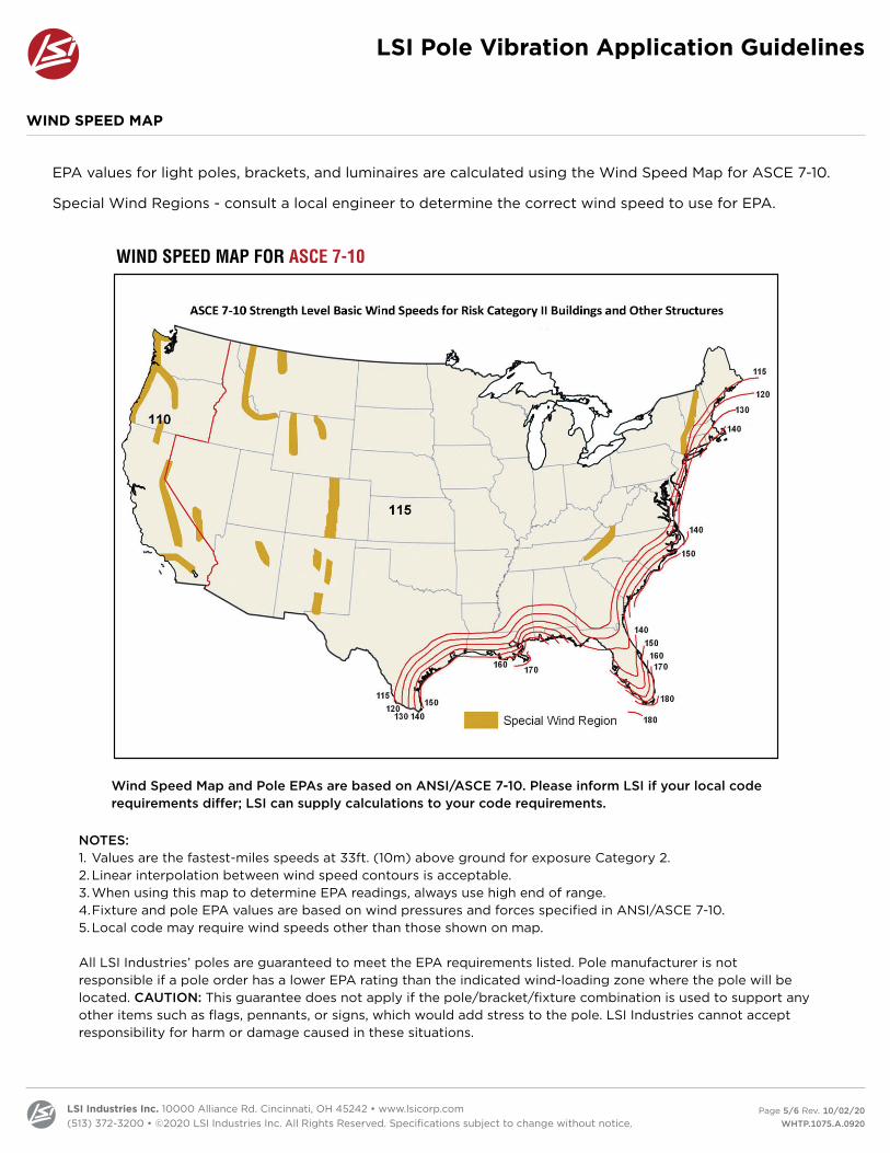
WIND SPEED MAP
EPA values for light poles, brackets, and luminaires are calculated using the Wind Speed Map for ASCE 7-10.
Special Wind Regions - consult a local engineer to determine the correct wind speed to use for EPA.
Wind Speed Map and Pole EPAs are based on ANSI/ASCE 7-10. Please inform LSI if your local code requirements differ; LSI can supply calculations to your code requirements.
NOTES:1. Values are the fastest-miles speeds at 33ft. (10m) above ground for exposure Category 2.2. Linear interpolation between wind speed contours is acceptable.3. When using this map to determine EPA readings, always use high end of range.4. Fixture and pole EPA values are based on wind pressures and forces specified in ANSI/ASCE 7-10.5. Local code may require wind speeds other than those shown on map.
All LSI Industries’ poles are guaranteed to meet the EPA requirements listed. Pole manufacturer is not responsible if a pole order has a lower EPA rating than the indicated wind-loading zone where the pole will be located. CAUTION: This guarantee does not apply if the pole/bracket/fixture combination is used to support any other items such as flags, pennants, or signs, which would add stress to the pole. LSI Industries cannot accept responsibility for harm or damage caused in these situations.
LSI Pole Vibration Application Guidelines
© 2019 LSI INDUSTRIES INC.
Project Name Fixture Type
Catalog #© 2017
LSI INDUSTRIES INC.
Project Name Fixture Type
Catalog #
WIND SPEED MAP FOR ASCE 7-10
Wind Speed Map and Pole EPAs are based on ANSI/ASCE 7-10. Please inform LSI if your local code requirements differ; LSI can supply calculations to your code requirements.
NOTES:1. Values are the fastest-mile speeds at 33 ft. (10 m) above ground for exposure Category 2.2. Linear interpolation between wind speed contours is acceptable.3. When using this map to determine EPA readings, always use high end of range.4. Fixture and pole EPA values are based on wind pressures and forces specified in ANSI/ASCE 7-10.5. Local code may require wind speeds other than those shown on map.
All LSI Industries’ poles are guaranteed to meet the EPA requirements listed. Pole manufacturer is not responsible if a pole order has a lower EPA rating than theindicated wind-loading zone where the pole will be located. CAUTION: This guarantee does not apply if the pole/bracket/ fixture combination is used to supportany other items such as flags, pennants, or signs, which would add stress to the pole. LSI Industries cannot accept responsibility for harm or damage caused inthese situations.
5/21/11

LSI Industries Inc. 10000 Alliance Rd. Cincinnati, OH 45242 • www.lsicorp.com(513) 372-3200 • ©2020 LSI Industries Inc. All Rights Reserved. Specifications subject to change without notice.
Page 6/6 Rev. 10/02/20 WHTP.1075.A.0920
POLE INSPECTION AND MAINTENANCE
LIMITED WARRANTY - POLES
Pole inspection and maintenance are very important to the longevity of the pole. It is imperative that destructive pole vibration be minimized in a timely manner before structural damage can occur. Inspections should be performed on a regular basis, beginning when the pole is installed and then after one week, one month, six months and annually. Pole inspections should also be performed after major wind events, as well as when environmental changes to the location could alter wind patterns – i.e. new construction, removal of buildings, or modification to landscaping. If any changes exist, a pole can be compromised in a short period of time, which can result in pole failure. Indications of pole vibration can be observed with the below guidelines:
• Visually inspect for signs of corrosion directly above the baseplate weld and around the hand hole. Corrosion and hairline cracks in the finish may suggest material fatigue.
• During windy conditions, observe the top of pole for excessive deflection and look for rapid oscillation at the middle of the pole. In addition, listen to hear if wires inside the pole are banging against the sides.
• Check the torque values of the anchor bolts. Low torque values could indicate vibration.
• Loosening of threaded attachments, fasteners of the luminaire and missing pole caps.
A structural engineer should be consulted if signs of pole fatigue exist. The affected pole should be dismantled, and a complete site inspection should be performed. If vibration is, or has, occurred but the pole is still deemed structurally sound, mitigation steps including adding a damper should be performed. If vibration is still present after mitigation, an alternate pole shape should be considered.
Many factors need to align to create wind induced pole vibration and may be isolated to one location on the site. Some factors include:
• Project is in a wide-open area • Pole is greater than or equal to 25’ and a load of less than a 2.0 EPA• Pole shape, square being the most susceptible to pole vibration• If vibration has been an issue in the past in that area
If these any of these factors are present, it is recommended that a pole damper be installed to reduce the risk of pole failure due to wind induced pole vibration.
LSI Pole Vibration Application Guidelines
Pole fatigue, damage or failure caused by or resulting from induced vibration, harmonic vibration or resonance associated with the movement of air currents around the product or by any other local condition are specifically excluded from this warranty.
SUMMARY