ls-dyna features: reinforced concrete beams and shells with *mat concrete...
TRANSCRIPT

LS-DYNA features:
Reinforced Concrete beams and shells
with *MAT_CONCRETE_EC2
This presentation is a basic introduction to *MAT_CONCRETE_EC2 (also known as *MAT_172). For further details see under Remarks in the Keyword Manual.

2
• Reinforced concrete shells & beams for structural engineering
- Element sizes typically ~ 0.1 to ≥1 metre
- Not modelling the individual rebars
• Applicable to:
- Quasi-static, basic structural applications
- Cyclic loading e.g. seismic
- Fire engineering
• Not applicable to:
- High strain-rate applications
- Applications where rebars need to be modelled individually
- Cracking due to through-thickness shear
- 3D effects or highly confined concrete
• Defaults taken from Eurocode 2 (“EC2”)
*MAT_CONCRETE_EC2

3
• *MAT_CONCRETE_EC2 can model concrete and/or reinforcement, determined by parameter FRACR
- Plain concrete: FRACR=0
- Reinforcement: FRACR=1
- Smeared, e.g. FRACR=0.02
Concrete and/or reinforcement
Concrete –
basic inputs
Rebar inputs
Here, FRACR means the maximum out of
FRACRX and FRACRY (reinforcement
fractions in local X and Y directions
Additional
inputs

4
Beams Shells
Smeared
reinforcement
Uniform material
properties e.g. 98%
concrete, 2% steel
Detailed
reinforcement
Separate material
properties for concrete
and steel
Input methods for defining reinforcement
*SECTION_BEAM, e.g.
NIP=5-10 (n x n int points)
*SECTION_SHELL, e.g.
NIP=5-10 (int pts thru thk)
*INTEGRATION_BEAM,
Define location, area and
material of each int pt.
*PART_COMPOSITE,
Define thickness and
material of each layer.
Concrete
Reinforcement

5
Layered shell model - reinforcement
w w
tw × t = A
Real Section LS-DYNA
Area A

Concrete properties: basic
Basic inputs
N.B. elastic modulus not defined…
As a minimum, define MID, Density RO, Compressive strength FC, and Tensile strength FT.
Recommended also to define aggregate size AGGSZ together with length unit factor UNITL.

Concrete properties: basic
At its simplest, the user defines only FT and FC. The above stress-strain relation is
generated automatically using data and formulae from Eurocode 2.
strain
stress
Tension: cracking with bi-linear
tension-stiffening
Compression: crushing
(yield-type behaviour)
-FC
FT-εc1-εcu
Default:
0.0025
Initial Young’s Modulus =
3FC/2εc1
Default:
0.02

8
• Smeared crack: mesh does not split apart; the presence of the crack is modelled in
the stress-strain behaviour
• Cyclic behaviour: crack opening displacement is tracked
Concrete: cracking behaviour
Crack opening
displacement
Crack must
close before
compression
can be resisted
Crack forms in
response to
tensile stress

9
• Non-rotating crack
- The first crack can form at any angle in
response to principal tensile stress
- The crack directions become fixed by
creation of the first crack
- Further cracks can form only at certain
angles to the first crack
Concrete: cracking behaviour Maximum
(tensile)
principal stress
First crack forms when maximum
tensile principal stress first reaches FT.
This sets the angle of cracks in this
element for the rest of the analysis.
LS-DYNA R9 and
below: one further crack
can form at 90 degrees
to first crack
LS-DYNA R10
and above: three
further cracks
can form (90,
45, 135 degrees)

10
• Non-rotating crack
- The tensile strength limit FT applies only in directions perpendicular to a
potential crack
- After the first crack is formed, tensile stresses can exceed FT in directions that
are not perpendicular to a potential crack, e.g. at 45 degrees to the first crack in
LS-DYNA R9, or at 22.5 degrees to the first crack in LS-DYNA R10.
- The “error” (amount by which the tensile stress exceeds FT) is usually less in
R10 than in R9 – this is why the extra potential cracks were added in R10.
• Cracks form due to in-plane tension only, not through-thickness shear
Concrete: limitations
LS-DYNA R9 and
below: tensile stress at
45 degrees to first crack
could exceed FT.
LS-DYNA R10 and
above: tensile stress
at 22.5 degrees to first
crack could exceed
FT.
11
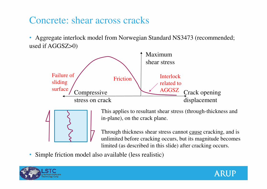
• Aggregate interlock model from Norwegian Standard NS3473 (recommended;
used if AGGSZ>0)
• Simple friction model also available (less realistic)
Concrete: shear across cracks
Interlock
related to
AGGSZ
FrictionFailure of
sliding
surface
This applies to resultant shear stress (through-thickness and
in-plane), on the crack plane.
Through thickness shear stress cannot cause cracking, and is
unlimited before cracking occurs, but its magnitude becomes
limited (as described in this slide) after cracking occurs.
Crack opening
displacement
Maximum
shear stress
Compressive
stress on crack

12
Concrete: yield surface (shells)σ2/fcu
σ1/fcu
*MAT_CONCRETE_EC2
Experimental
• Compatible with typical design
assumptions, rather than realistic
concrete behaviour
Axes show in-plane
principal stresses

13
• “Mander” compression curve (TYPEC=6). Fewer defaults, more user input. Mander, J.B., M.J.N. Priestley, and R. Park 1984. Theoretical Stress-Strain Model
for Confined Concrete. Journal of Structural Engineering. ASCE. 114(3). 1804-1826.
• Use different *MAT card properties for unconfined cover concrete versus confined concrete within the rebar cage
Concrete properties: for seismic analysis
strain
stressTension: cracking with bi-linear
tension-stiffening
Unconfined
(FCC=0)
-FC
FT-εc1
Initial Young’s
Modulus input by user
-FCC
Confined
(FCC > FC)
-εcu-εcsp

14
• TYPEC = 7,8
- Thermal expansion coefficients automatically generated (do not use
*MAT_ADD_THERMAL_EXPANSION)
- Material properties soften with increasing temperature
- Softening factors hard-wired to tabulated values in EC2-2 Annex
- Some user-input options also available
Concrete properties: for thermal/fire analysis
Example: stress/strain
relations for hot-rolled
reinforcing steel at elevated
temperatures, from EC2
(ENV 1992-1-2 1995)

15
Concrete: meanings of TYPECTYPEC Source of defaults Thermal
softening &
expansion
Notes/recommendation
0 1 2 4 5 Draft EC2 Annex (Fire
engineering)
ENV 1992-1-2:1995
Y Basic option
3 Simple non-thermally-
sensitive
N
6 Mander N Seismic analysis; input FCC>FC for
confined concrete
7 8 EC2-1-2:2004 (fire) Y Fire analysis
9 EC2 general struct. Engrg.
EC2 1-1:2004
N Use when close adherence to Eurocode is
important. Can input the concrete strength
class (e.g. 30 for C30 concrete) and let the
other properties be taken automatically
from EC2 1-1:2004 Table 3.1

16
• Reinforcement option within *MAT_CONCRETE_EC2
• Bars act uniaxially (no shear stress)
• Beams: bars act only in the beam’s axial direction
• Shells: separate area fractions are input for local X and Y directions; shear stress is zero in-plane and through-thickness.
- Use AOPT to define bar directions. Default: same as element local axes, i.e.
Node 1 to Node 2 is local X
Reinforcement: basic
Default:
Rebars aligned in
element X, Y axes
With AOPT:
Rebars at user-
controlled angle

17
Reinforcement: basic
To model smeared reinforcement: input
FRACRX and/or FRACRY = fraction of
reinforcement across whole section, e.g. 0.02
To model detailed reinforcement, i.e. an
integration point representing pure
reinforcement: input FRACRX = 1.0 and/or
FRACRY = 1.0
Simple elastic/perfectly plastic
stress/strain relation

18
Reinforcement: basic
Add a curve if required To model smeared reinforcement: input
FRACRX and/or FRACRY = fraction of
reinforcement across whole section, e.g. 0.02
To model detailed reinforcement, i.e. an
integration point representing pure
reinforcement: input FRACRX = 1.0 and/or
FRACRY = 1.0

19
• *MAT_HYSTERETIC_REINFORCEMENT (*MAT_203)
• Use within reinforced concrete section defined by *PART_COMPOSITE or
*INTEGRATION_BEAM: Concrete = MAT_172, Reinforcement = MAT_203
Reinforcement: improved cyclic behaviour
A
A
A
A
Axial response with Bauschinger effect
(Example without bar buckling)
Shear – dowel action
(optional)

20
• *MAT_HYSTERETIC_REINFORCEMENT (*MAT_203)
Reinforcement: improved cyclic behaviour
Axial response with
Bauschinger effect
(Example with bar buckling,
invoked by inputting the
slenderness ratio LAMDA)

*MAT_HYSTERETIC_REINFORCEMENT
Basic inputs Bar buckling
Dowel action