lrfd bds section 6, various articles - texas department … · 2016-10-18 · lrfd bds section 6,...
TRANSCRIPT

AASHTO Design and Material Specification
Changes2016
LRFD BDS Section 6, Various Articles
Karl H. FrankChief Engineer
Hirschfeld Industries

Bolts
2
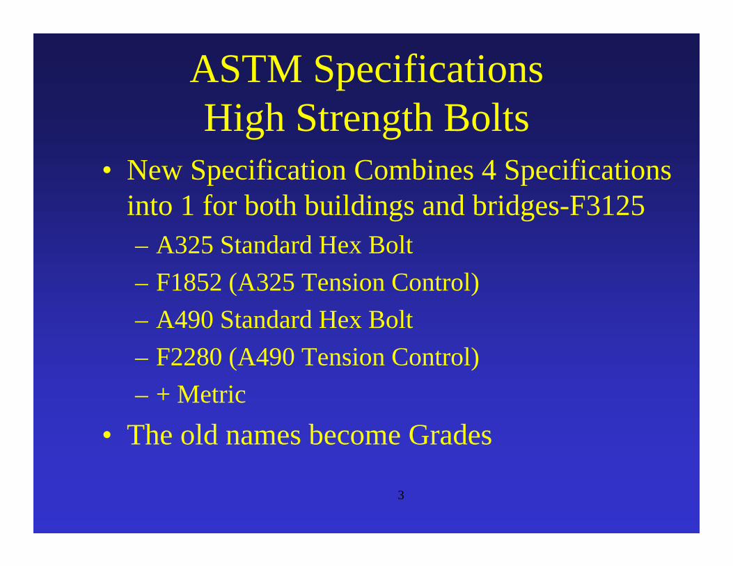
ASTM SpecificationsHigh Strength Bolts
• New Specification Combines 4 Specifications into 1 for both buildings and bridges-F3125– A325 Standard Hex Bolt– F1852 (A325 Tension Control)– A490 Standard Hex Bolt– F2280 (A490 Tension Control)– + Metric
• The old names become Grades
3
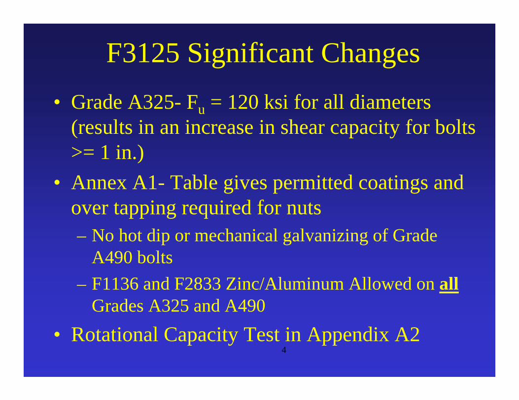
F3125 Significant Changes• Grade A325- Fu = 120 ksi for all diameters
(results in an increase in shear capacity for bolts >= 1 in.)
• Annex A1- Table gives permitted coatings and over tapping required for nuts– No hot dip or mechanical galvanizing of Grade
A490 bolts– F1136 and F2833 Zinc/Aluminum Allowed on all
Grades A325 and A490• Rotational Capacity Test in Appendix A2
4

AASHTO LRFD Changes
• Bolt Shear Strength• Slip Critical Categories• Standard Hole Sizes• Girder Field Splice Design
KHF
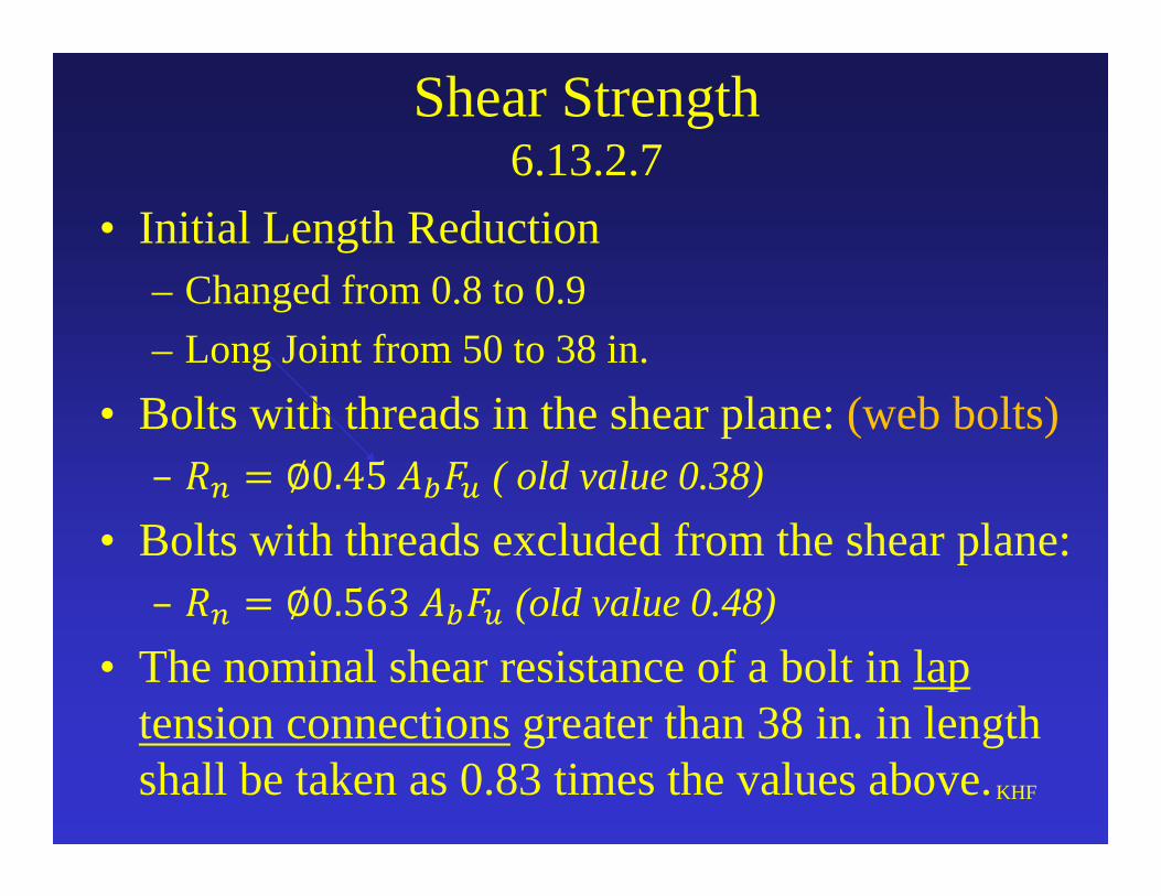
Shear Strength 6.13.2.7
• Initial Length Reduction– Changed from 0.8 to 0.9– Long Joint from 50 to 38 in.
• Bolts with threads in the shear plane: (web bolts)( old value 0.38)
• Bolts with threads excluded from the shear plane:(old value 0.48)
• The nominal shear resistance of a bolt in lap tension connections greater than 38 in. in length shall be taken as 0.83 times the values above.KHF
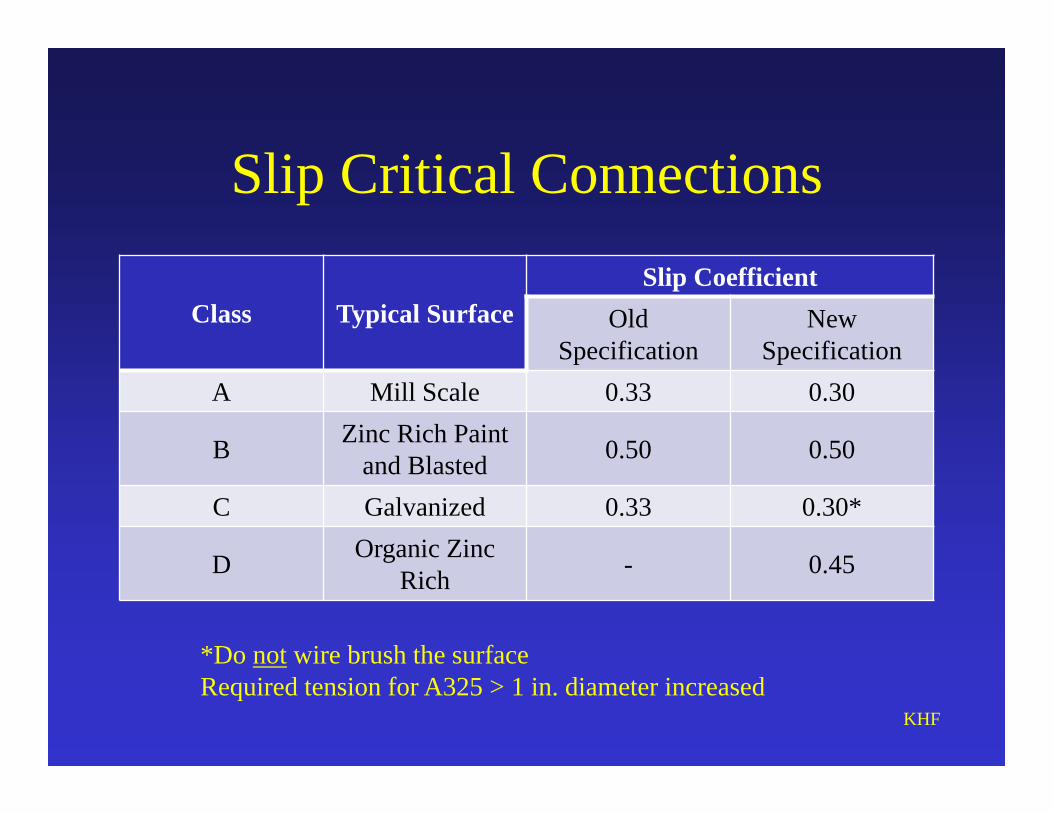
Slip Critical Connections
Class Typical SurfaceSlip Coefficient
Old Specification
New Specification
A Mill Scale 0.33 0.30
B Zinc Rich Paint and Blasted 0.50 0.50
C Galvanized 0.33 0.30*
D Organic Zinc Rich - 0.45
KHF
*Do not wire brush the surfaceRequired tension for A325 > 1 in. diameter increased

Footnote on Bolting• New Hole Size
– 1 inch and greater: Standard hole = diameter of fastener +1/8 in.
• Miss drilled holes- fill with fully tensioned high strength bolt (Category B fatigue strength)
• New electric wrenches can be programmed for required turn of the nut

New Connection Design Criteria and Methods
Remove applicability of the 75 percent and average rules in Article 6.13.1 to the design of bolted and welded splices for flexural members.
75 percent rules are applicable to connections and splices for primary members subject to axial tension or compression only.
Clarify application of rules to primary members subjected to force effects acting in multiple directions due to combined loading.

Bolted Field Splices of Flexural Members
Revise general article on design of bolted splices for flexural members implementing new simplified bolted splice design procedure
Removal of check for slip of bolts during erection of steel
• The purpose is implementation of simplified design procedure and more economical field splice designs.
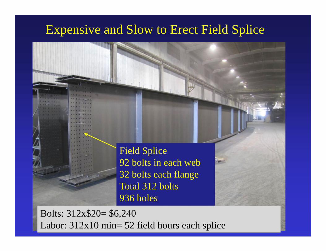
Expensive and Slow to Erect Field Splice
Field Splice92 bolts in each web32 bolts each flangeTotal 312 bolts936 holes
Bolts: 312x$20= $6,240Labor: 312x10 min= 52 field hours each splice
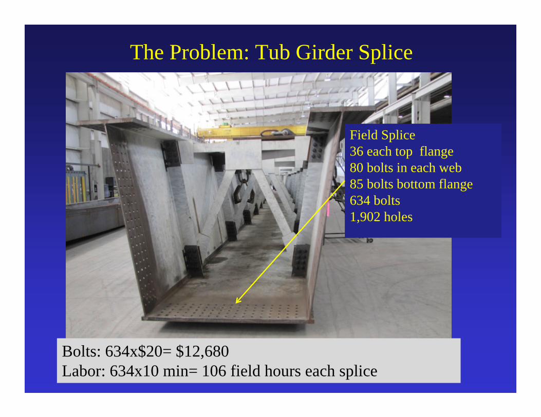
The Problem: Tub Girder Splice
Field Splice36 each top flange80 bolts in each web85 bolts bottom flange634 bolts1,902 holes
Bolts: 634x$20= $12,680Labor: 634x10 min= 106 field hours each splice
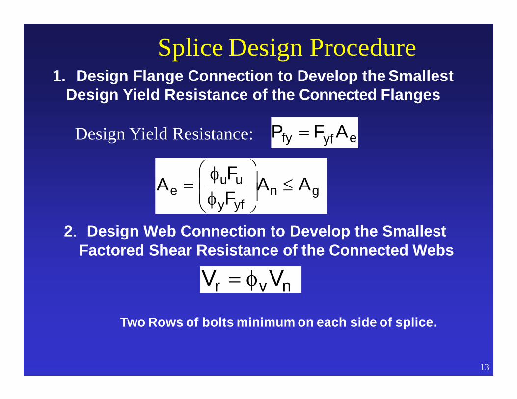
Splice Design Procedure1. Design Flange Connection to Develop the Smallest
Design Yield Resistance of the Connected Flanges
Design Yield Resistance:
2. Design Web Connection to Develop the Smallest Factored Shear Resistance of the Connected Webs
Two Rows of bolts minimum on each side of splice.
13
gnyfy
uue AA
FFA
nvr VV
eyffy AFP

Positive Moment Capacity CheckBottom Flange in Tension
Moment Capacity:Pfy for the Bottom Flange x Moment Arm to Mid- Depth of Deck
= (Fyf x Ae ) x A
14
2tt
2tDA s
haunchft
eyffy AFP

Negative Moment Capacity CheckIgnore Tensile Strength of Reinforcement
Moment Capacity:Smallest Value of Pfy x Distance Between FlangeCentroids
= (Fyf x Ae ) x A
15
2t
2tDA fcft
eyffy AF)top(P
eyffy AF.)bot(P

Additional Moment Provided by Web:Factored Design Moment – (Pfy x A) (flange moment)Web Contribution: Hw x Aw (web force at mid depth)
Positive MomentTake Moments about mid thickness of deck
16
2tt
2DA s
haunchw
wH
eyffy AFP
If Moment From Flanges is Not Sufficient
Negative MomentTake Moments about larger flange
2t
2DA f
w
wH
eyffy AFP
Flange with Largest Yield Capacity

Hw = (Additional required web moment) / Aw
17
Number Bolts Required = R / Bolt Capacity
Minimum of Two Rows each side of splice
Normally Maximum Spacing and 2 Row Requirement Controls Web Bolts
2w2
nv2
w2
r HVHVR
Resultant Web Force Moment and Shear
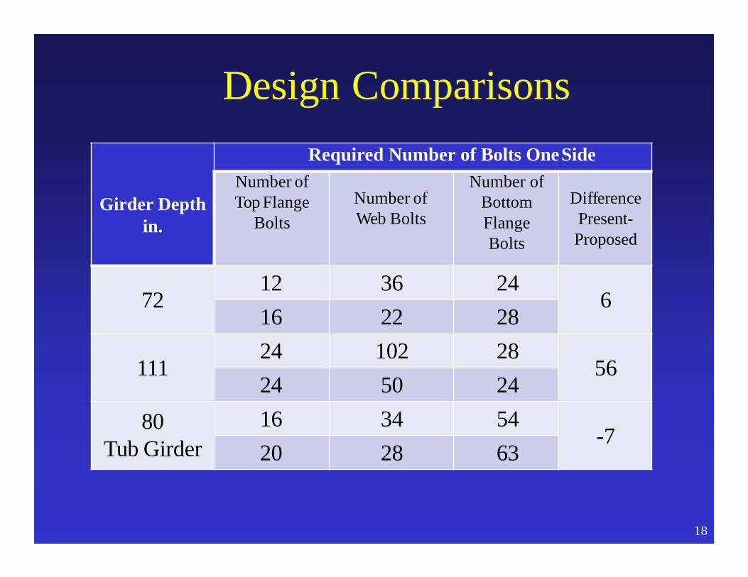
Design Comparisons
18
Girder Depth in.
Required Number of Bolts OneSideNumber of Top Flange
BoltsNumber of Web Bolts
Number of Bottom FlangeBolts
Difference Present-Proposed
7212 36 24
616 22 28
11124 102 28
5624 50 24
80Tub Girder
16 34 54-7
20 28 63
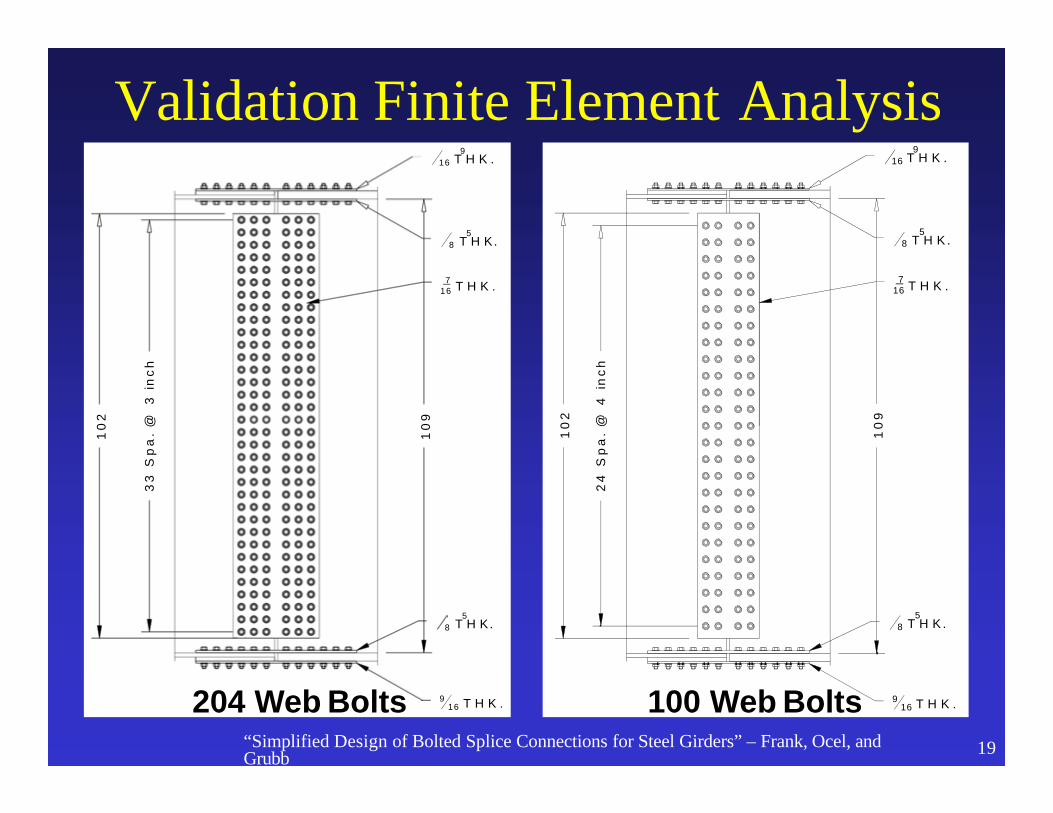
Validation Finite Element Analysis
10
9
916 T H K .
58 T H K.
58 T H K.
916 T H K .
716 T H K .
10
2
33
Sp
a.
@3
inc
h
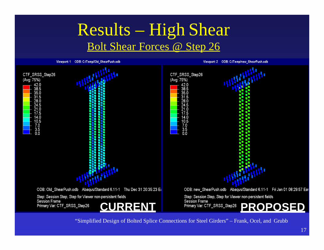
204 Web Bolts
10
9
916 T H K .
58 T H K .
58 T H K .
916 T H K .
716 T H K .
10
2
24
Sp
a.
@
4in
ch
100 Web Bolts“Simplified Design of Bolted Splice Connections for Steel Girders” – Frank, Ocel, and Grubb 19
20
o Shell element models in Abaquso Adapted fastener models from NCHRP 12-84o Five loading scenarios
– Pure positive moment– Pure negative moment *– High shear (as little moment as possible) *– Proportion design positive moment/shear– Proportional design negative moment/shear *
*= deck not present
FEA Model Description
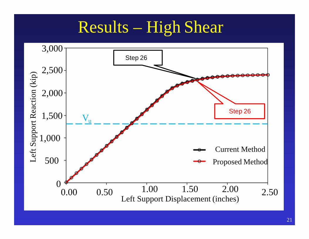
Results – High Shear
0
500
1,000
1,500
0.00 0.50 2.50
Left
Supp
ortR
eact
ion
(kip
)
1.00 1.50 2.00Left Support Displacement (inches)
Current Method Proposed Method
Vu
3,000
Step 26
21
2,000
2,500Step 26
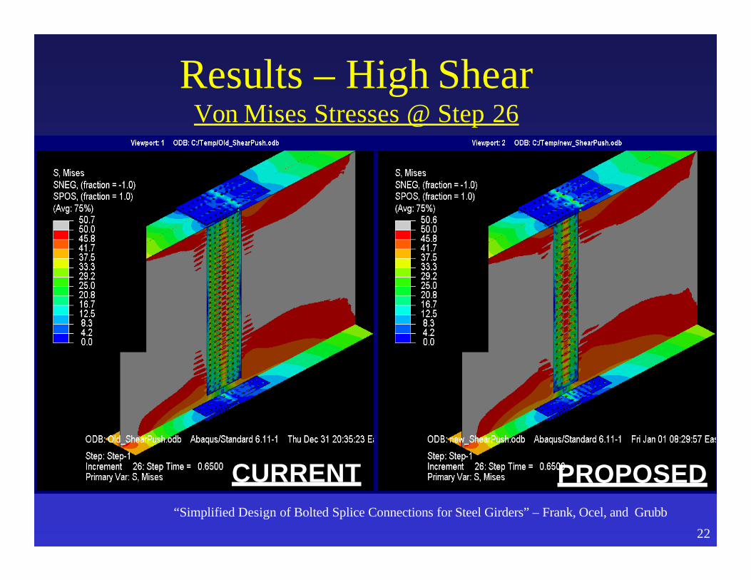
CURRENT“Simplified Design of Bolted Splice Connections for Steel Girders” – Frank, Ocel, and Grubb
22
PROPOSED
Results – High ShearVon Mises Stresses @ Step 26
CURRENT“Simplified Design of Bolted Splice Connections for Steel Girders” – Frank, Ocel, and Grubb
17
PROPOSED
Results – High ShearBolt Shear Forces @ Step 26

Results – Prop Neg Mom & Shear
0
20
500
1,000
1,500
3,000
2,500
2,000
0.00 0.50 1.00 1.50 2.00 2.50 3.00 3.50 4.00
Left
Supp
ortR
eact
ion
(kip
)
Left Support Displacement (inches)
Current Method Proposed Method
Vu
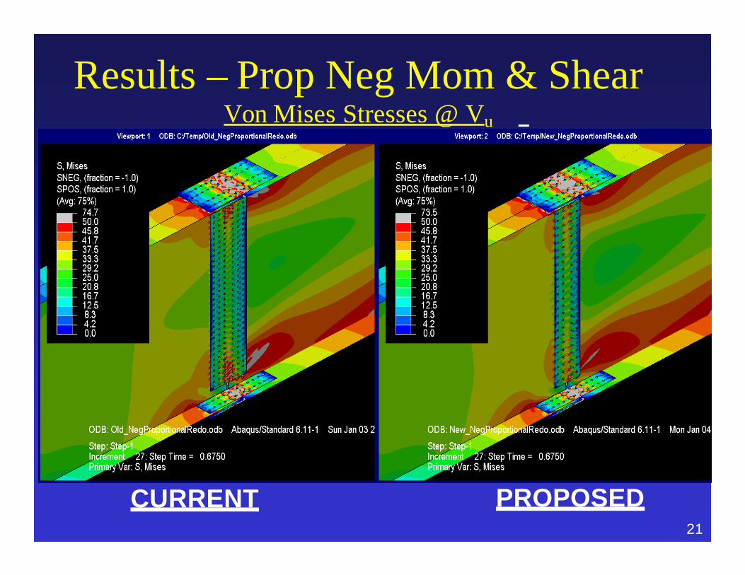
Results – Prop Neg Mom & ShearVon Mises Stresses @ Vu
CURRENT PROPOSED21

Results – Prop Neg Mom & ShearBolt Shear Forces @ Vu
CURRENT PROPOSED24

– Application of the new proposed design provisions for bolted field splices will typically result in a few more bolts in the flange splices and significantly fewer bolts in the web splices than under the current design provisions.
– The overall simplification in the design procedure should result in easier interpretation of the provisions, faster and more efficient design of field splices, and more consistent and cost-effective designs.
– Clarifications to the application of the 75 percent and average rules to the design of connections and splices in primary members at the strength limit state subject to combined force effects should also be beneficial to designers.
Anticipated Effect on Bridges:
Result of Changes to Field Splice Design
• Reduced Design Effort and Cost, Lower Connection Costs, & Faster Erection
KHF

A New Day- Another Bridge
29
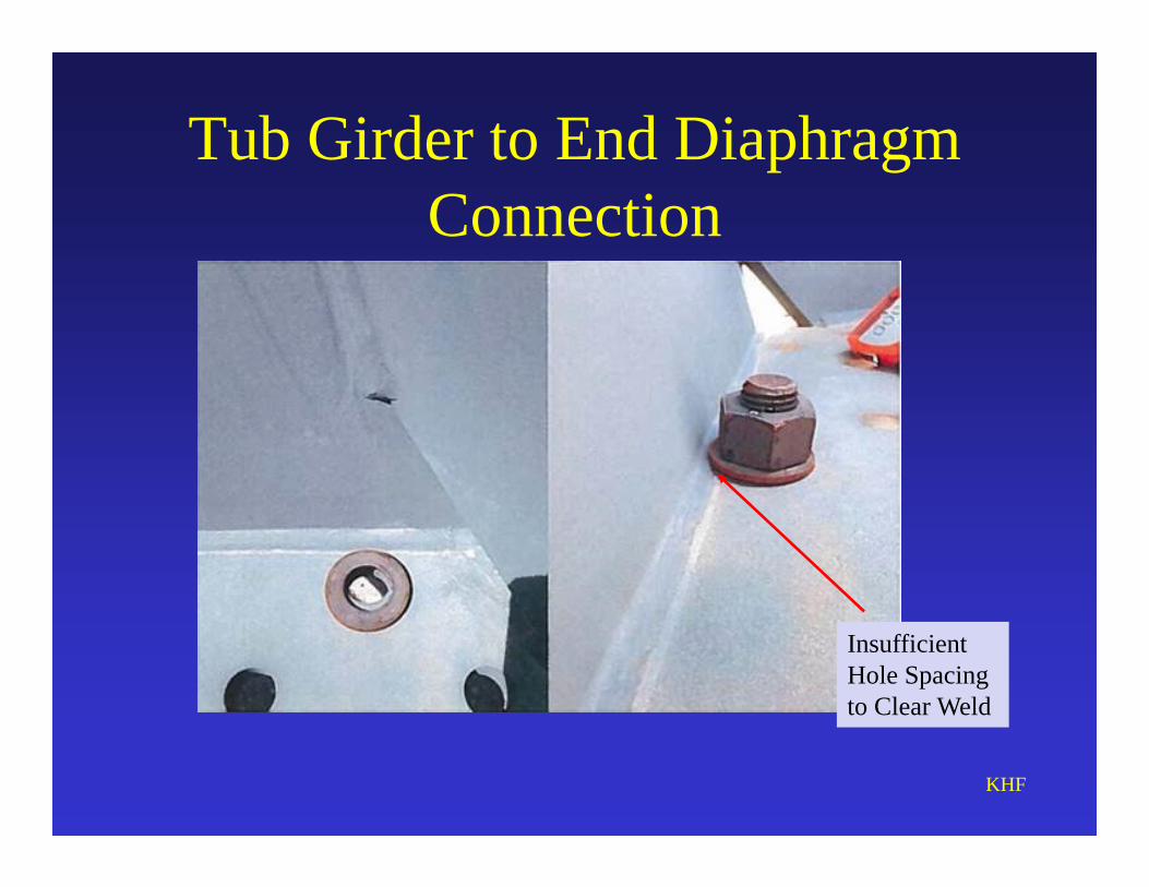
Tub Girder to End Diaphragm Connection
KHF
Insufficient Hole Spacing to Clear Weld

End Section of Skewed Dapped Tub Girder
KHFThe Problem Area
80 bolts each flange!
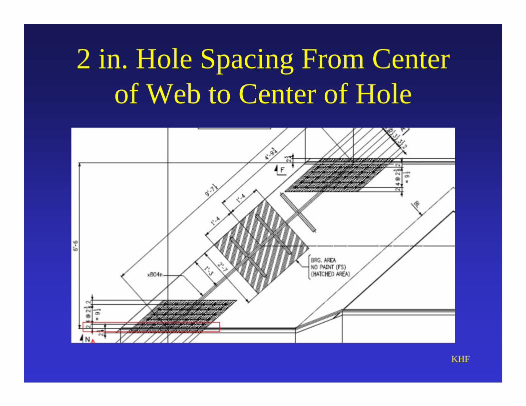
2 in. Hole Spacing From Center of Web to Center of Hole
KHF
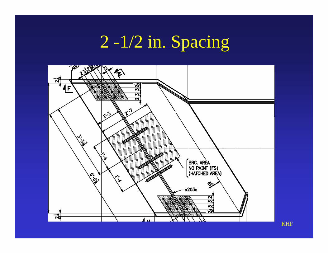
2 -1/2 in. Spacing
KHF
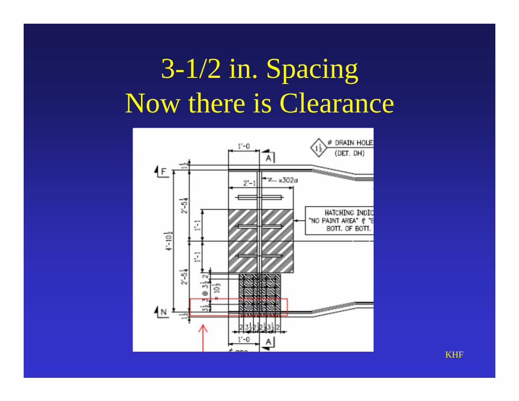
3-1/2 in. SpacingNow there is Clearance
KHF