lqr controller design for stabilization of cart model ... · lqr controller design for...
TRANSCRIPT

International Journal of Science and Research (IJSR) ISSN (Online): 2319-7064
Index Copernicus Value (2013): 6.14 | Impact Factor (2013): 4.438
Volume 4 Issue 7, July 2015
www.ijsr.net Licensed Under Creative Commons Attribution CC BY
LQR Controller Design for Stabilization of Cart
Model Inverted Pendulum
Shireen S. Sonone1, N. V. Patel
2
1Department of Electrical Engineering, Walchand College of Engineering, Sangli(M.S.), India
2Associate Professor, Dept. of Electrical Engineering, Walchand College of Engineering, Sangli (M.S.), India
Abstract: Optimal response of the controlled dynamical systems is desired hence for that is the optimal control. Linear Quadratic
Regulator (LQR), an optimal control method, and PID control which are generally used for control of the linear dynamical systems have
been used in this paper to control the nonlinear dynamical system. The inverted pendulum, a highly nonlinear unstable system is used as
a benchmark for implementing the control methods. In this paper the modeling and control design of nonlinear inverted pendulum-cart
dynamic system with disturbance input using PID control & LQR have been presented. The nonlinear system states are fed to LQR
which is designed using linear state-space model. Here PID & LQR control methods have been implemented to control the cart position
and stabilize the inverted pendulum in vertically uprightposition. The MATLAB-SIMULINK models have been developed for simulation
of the control schemes. The simulation results justify the comparative advantages of LQR control methods.
Keywords: Inverted Pendulum, Nonlinear System, PID Control,Optimal Control, LQR, Disturbance Input
1. Introduction
Inverted pendulum system is a typical model of
multivariable, nonlinear, essentially unsteady system, which
is perfect experiment equipment not only for pedagogy but
for research because many abstract concepts of control
theory can be demonstrated by the system-based experiments
[1]. The research on such a complex system involves many
important theory problems about system control, such as
nonlinear problems, robustness, ability and tracking
problems. Therefore, as an ideal example of the study, the
inverted pendulum system in the control system has been
universal attention. And it has been recognized as control
theory, especially the typical modern control theory research
and test equipment. So it is not only the best experimental
tool but also an ideal experimental platform. The research of
inverted pendulum has profound meaning in theory and
methodology, and has valued by various countries' scientists
[2].
The problem is referred in classical literature as pole
balancer control problem, cart-pole problem, broom balancer
control problem, stick balancer control problem, inverted
pendulum control problem [3]. Control of inverted pendulum
resembles the control systems that exist in some of the real
time applications such as rockets and missiles, heavy crane
lifting containers and self-balancing robots. According to
control purposes of inverted pendulum, the control of
inverted pendulum can be divided into three aspects. The
first aspect widely researched is the swing-up control of
Inverted Pendulum (IP) [4,5]. The second aspect is the
stabilization of the inverted pendulum [6-7]. The third aspect
is tracking control of the inverted pendulum [8]. In practice,
stabilization and tracking control is more useful for plenty of
real time applications. There are several problems to be
solved in the control of inverted pendulum, such as swinging
up and catching the pendulum from its stable pending
position to the upright unstable position, and then balancing
the pendulum at the upright position during disturbances,and
further move the cart to a specified position on the rail [9].
Several methods for achieving swing-up and stabilization of
pendulum system have been proposed in literature. However,
in practical setups, there is an inherent limitation on the cart
length and the magnitude of control force that can be
applied. This gives the motivation to find out energy based
methods for controlling and stabilizing the cart position with
restricted cart length and restricted control force.In addition,
the inverted pendulum has always been adopted as a classical
control example to test the advantages and disadvantages of
various control algorithms such as PID control, state
feedback control, fuzzy control, neural network control,
adaptive control and genetic algorithms.
2. Mathematical Modelling
Figure 1: Analysis of Forces on Cart and Pendulum
Let H the horizontal component of reaction force and V be
vertical component of reaction force. Let x1 be the horizontal
component of co-ordinates of Centre of Gravity (COG) and
y1 be the vertical component of co-ordinates of COG.
Define the angle of the rod from the vertical (reference) line
as θ and displacement of the cart as x. Also assume the force
applied to the system is F, g be the acceleration due to
Paper ID: SUB156519 1172

International Journal of Science and Research (IJSR) ISSN (Online): 2319-7064
Index Copernicus Value (2013): 6.14 | Impact Factor (2013): 4.438
Volume 4 Issue 7, July 2015
www.ijsr.net Licensed Under Creative Commons Attribution CC BY
gravity and l be the half length of the pendulum rod, v , and
w be the translational and angular velocity of the cart and
pendulum. Let H be the horizontal component of reaction
force and V be vertical component of reaction force. So the
horizontal reaction force H becomes:-
The forced F applied on the cart equals the sum of the force
due to acceleration, friction component of force that opposes
the linear motion of the cart and the horizontal reaction.
Thus we get
The Vertical reaction V can be expressed as:-
Torque equation is,
Thus,
The following is the parameter table that gives the value of
the various parameters that has been adopted from the
Feedback Digital Pendulum Manual.
Table 1: Parameters from Feedback Digital Pendulum
Manual
Symbol Parameter Value Unit
M Cart Mass 2.4 Kg
m Pole Mass 0.23 Kg
l Pole Length 0.4 m
b Cart Friction coefficient 0.05 Ns/m
d Pendulum damping coefficient 0.005 Nms/m
I Moment of Inertia of the pole 0.099 Kg.m2
g Gravity 9.81 m/s2
Using above equations and substituting the parameters, we
get the following state space equation
3. LQR Design
A system can be expressed in state variable form as x = Ax +
Bu with x(t)∈R N, u(t)∈ R N . The initial condition is x(0) .
We assume here that all the states are measurable and seek to
find a State-Variable Feedback (SVFB) control.
u = −Kx + v
This equation gives desired closed-loop properties. The
closed-loop system using this control becomes
x = (A- BK) x+ B
v= Ac x+ Bv
With Ac the closed-loop plant matrix and v the new
command input. Ackermann's formula gives a SVFB K that
places the poles of the closed-loop system at desired
location. Todesign a SVFB that is optimal, we may define
the performance index J as
𝐽 =1
2 𝑥𝑇(𝑄 + 𝐾𝑇𝑅𝐾
∞
0
)𝑥 𝑑𝑡
Optimal solution for closed loop system is obtained by
𝑥 = 𝐴𝑥 + 𝐵𝑢, 𝑥 𝑡0 = 𝑥0
𝜆 = −𝑄𝑥 − 𝐴𝑇𝜆
𝑅𝑢 + 𝐵𝑇𝜆 = 0
As the above equations are linear we can connect them as
λ=Px
Here, P is the solution to Algebraic Riccatti Equation given
as
𝐴𝑇𝑃 + 𝑃𝐴 + 𝑄 − 𝑃𝐵𝑅−1𝐵𝑇𝑃 = 0 Optimal control law is given as,
u= - Kx
But from equation (a),
u=R-1
BT λ
Hence,
K=R-1
BTP
Where, K is Optimal Feedback Gain Matrix.
4. Simulations and Results
The MATLAB-SIMULINK models for the simulation of
modeling, analysis, and control of nonlinear inverted
pendulum-cart dynamical system with disturbance input have
been developed. The typical parameters of inverted
pendulum cart system setup are selected as [16,20]: mass of
the cart (M):2.4 kg, mass of the pendulum (m): 0.23 kg,
length of the pendulum (l): 0.36 m, length of the cart track
(L): ± 0.5 m, friction coefficient of the cart & pole rotation is
assumed negligible. The disturbance input parameters which
has been taken in simulation are [21]: Band Limited White
Noise Power= 0.001, Sample Time = 0.01, Seed = 23341.
Here three control schemes have been implemented for
optimal control of nonlinear inverted pendulum-cart
dynamical system with disturbance input: 1. PID control
method having two PIDs i.e. angle PID & cart PID, 2. Two
PIDs (i.e. angle PID & cart PID) with LQR control method,
3. One PID (i.e.cart PID) with LQR control method.
In the optimal control of nonlinear inverted pendulum
dynamical system using PID controller & LQR approach, all
the instantaneous states of the nonlinear system, pendulum
angle θ , angular velocity θ, cart position x , and cart velocity
x have been considered available for measurement which are
directly fed to the LQR. The LQR is designed using the
linear state-space model of the system. The optimal control
value of LQR is added negatively with PID control value to
have a resultant optimal control. The tuning of the PID
controllers which are used here either as PID control method
or PID+LQR control methods is done by trial & error
method and observing the responses achieved to be optimal.
The SIMULINK model for control of inverted pendulum
system with disturbance input using PID control method
fornon linear plant model is shown in Fig.4.1.
Paper ID: SUB156519 1173
International Journal of Science and Research (IJSR) ISSN (Online): 2319-7064
Index Copernicus Value (2013): 6.14 | Impact Factor (2013): 4.438
Volume 4 Issue 7, July 2015
www.ijsr.net Licensed Under Creative Commons Attribution CC BY
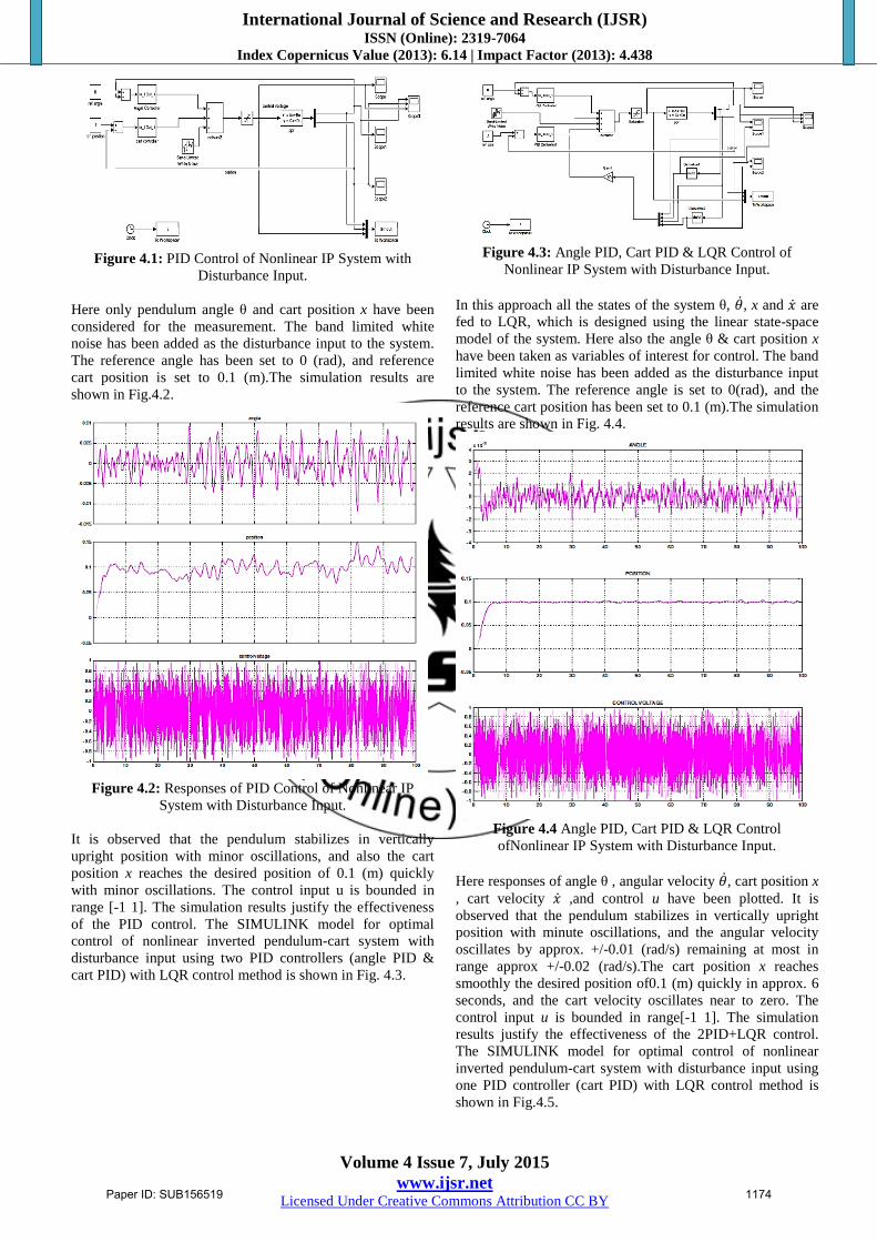
Figure 4.1: PID Control of Nonlinear IP System with
Disturbance Input.
Here only pendulum angle θ and cart position x have been
considered for the measurement. The band limited white
noise has been added as the disturbance input to the system.
The reference angle has been set to 0 (rad), and reference
cart position is set to 0.1 (m).The simulation results are
shown in Fig.4.2.
Figure 4.2: Responses of PID Control of Nonlinear IP
System with Disturbance Input.
It is observed that the pendulum stabilizes in vertically
upright position with minor oscillations, and also the cart
position x reaches the desired position of 0.1 (m) quickly
with minor oscillations. The control input u is bounded in
range [-1 1]. The simulation results justify the effectiveness
of the PID control. The SIMULINK model for optimal
control of nonlinear inverted pendulum-cart system with
disturbance input using two PID controllers (angle PID &
cart PID) with LQR control method is shown in Fig. 4.3.
Figure 4.3: Angle PID, Cart PID & LQR Control of
Nonlinear IP System with Disturbance Input.
In this approach all the states of the system θ, 𝜃 , x and 𝑥 are
fed to LQR, which is designed using the linear state-space
model of the system. Here also the angle θ & cart position x
have been taken as variables of interest for control. The band
limited white noise has been added as the disturbance input
to the system. The reference angle is set to 0(rad), and the
reference cart position has been set to 0.1 (m).The simulation
results are shown in Fig. 4.4.
Figure 4.4 Angle PID, Cart PID & LQR Control
ofNonlinear IP System with Disturbance Input.
Here responses of angle θ , angular velocity 𝜃 , cart position x
, cart velocity 𝑥 ,and control u have been plotted. It is
observed that the pendulum stabilizes in vertically upright
position with minute oscillations, and the angular velocity
oscillates by approx. +/-0.01 (rad/s) remaining at most in
range approx +/-0.02 (rad/s).The cart position x reaches
smoothly the desired position of0.1 (m) quickly in approx. 6
seconds, and the cart velocity oscillates near to zero. The
control input u is bounded in range[-1 1]. The simulation
results justify the effectiveness of the 2PID+LQR control.
The SIMULINK model for optimal control of nonlinear
inverted pendulum-cart system with disturbance input using
one PID controller (cart PID) with LQR control method is
shown in Fig.4.5.
Paper ID: SUB156519 1174
International Journal of Science and Research (IJSR) ISSN (Online): 2319-7064
Index Copernicus Value (2013): 6.14 | Impact Factor (2013): 4.438
Volume 4 Issue 7, July 2015
www.ijsr.net Licensed Under Creative Commons Attribution CC BY
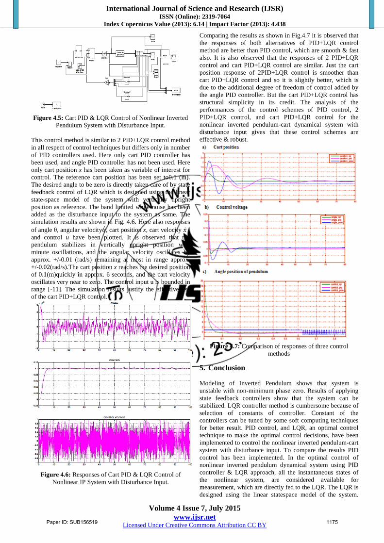
Figure 4.5: Cart PID & LQR Control of Nonlinear Inverted
Pendulum System with Disturbance Input.
This control method is similar to 2 PID+LQR control method
in all respect of control techniques but differs only in number
of PID controllers used. Here only cart PID controller has
been used, and angle PID controller has not been used. Here
only cart position x has been taken as variable of interest for
control. The reference cart position has been set to0.1 (m).
The desired angle to be zero is directly taken care of by state
feedback control of LQR which is designed using the linear
state-space model of the system with vertically upright
position as reference. The band limited white noise has been
added as the disturbance input to the system as same. The
simulation results are shown in Fig. 4.6. Here also responses
of angle θ, angular velocity𝜃 , cart position x, cart velocity 𝑥 , and control u have been plotted. It is observed that the
pendulum stabilizes in vertically upright position with
minute oscillations, and the angular velocity oscillates by
approx. +/-0.01 (rad/s) remaining at most in range approx.
+/-0.02(rad/s).The cart position x reaches the desired position
of 0.1(m)quickly in approx. 6 seconds, and the cart velocity
oscillates very near to zero. The control input u is bounded in
range [-11]. The simulation results justify the effectiveness
of the cart PID+LQR control.
Figure 4.6: Responses of Cart PID & LQR Control of
Nonlinear IP System with Disturbance Input.
Comparing the results as shown in Fig.4.7 it is observed that
the responses of both alternatives of PID+LQR control
method are better than PID control, which are smooth & fast
also. It is also observed that the responses of 2 PID+LQR
control and cart PID+LQR control are similar. Just the cart
position response of 2PID+LQR control is smoother than
cart PID+LQR control and so it is slightly better, which is
due to the additional degree of freedom of control added by
the angle PID controller. But the cart PID+LQR control has
structural simplicity in its credit. The analysis of the
performances of the control schemes of PID control, 2
PID+LQR control, and cart PID+LQR control for the
nonlinear inverted pendulum-cart dynamical system with
disturbance input gives that these control schemes are
effective & robust.
Figure 4.7: Comparison of responses of three control
methods
5. Conclusion
Modeling of Inverted Pendulum shows that system is
unstable with non-minimum phase zero. Results of applying
state feedback controllers show that the system can be
stabilized. LQR controller method is cumbersome because of
selection of constants of controller. Constant of the
controllers can be tuned by some soft computing techniques
for better result. PID control, and LQR, an optimal control
technique to make the optimal control decisions, have been
implemented to control the nonlinear inverted pendulum-cart
system with disturbance input. To compare the results PID
control has been implemented. In the optimal control of
nonlinear inverted pendulum dynamical system using PID
controller & LQR approach, all the instantaneous states of
the nonlinear system, are considered available for
measurement, which are directly fed to the LQR. The LQR is
designed using the linear statespace model of the system.
Paper ID: SUB156519 1175

International Journal of Science and Research (IJSR) ISSN (Online): 2319-7064
Index Copernicus Value (2013): 6.14 | Impact Factor (2013): 4.438
Volume 4 Issue 7, July 2015
www.ijsr.net Licensed Under Creative Commons Attribution CC BY
The optimal control value of LQR is added negatively with
PID control value to have a resultant optimal control. The
MATLAB-SIMULINK models have been developed for
simulation of the control schemes. The tuning of the PID
controllers which are used here either as PID control method
or PID+LQR control methods is done by trial & error
method and observing the responses achieved to be optimal.
The simulation results justify the comparative advantages of
optimal control using LQR method. The pendulum stabilizes
in upright position with acceptable minor oscillations and
cart approaches the desired position even under the
continuous disturbance input such as wind force justify that
the control schemes are effective & robust. The response of
PID controller using LQR is better than PID controller.
References
[1] HongliangWang ;Haobin Dong ; Lianghua He ; Yongle
Shi ; Yuan Zhang , “Design and Simulation of LQR
Controller with the Linear Inverted Pendulum”, Electrical
and Control Engineering (ICECE), 2010 International
Conference ,pp 699-702.
[2] Yuqing Li, Huajing Fang, “Modeling and Analysis of
Networked Control Systems with Network-Induced
Delay and Multiple-Packet Transmission”, ICARCV
2008, pp 494-498, 2008.
[3] Vinodh Kumar E, JovithaJerome ,“ Robust LQR
Controller Design For Stabilizing and trajectory Tracking
of Inverted Pendulum”, presented at International
Conference on DESIGN AND MANUFACTURING,
IConDM 2013.
[4] Jia-Jun Wang, 2011.Simulation studies of inverted
pendulum based on PID controllers, Simulation
Modelling Practice and Theory 19 (2), pp. 440 449.
[5] P. Mason, M. Broucke, B. Piccoli, 2008.Time optimal
swing-up of the planar pendulum, IEEE Transactions on
Automatic Control 53 (8), pp. 1876 1886.
[6] C.W. Tao, J.S. Taur, T.W. Hsieh, C.L. Tsai, 2008. Design
of a fuzzy controller with fuzzy swing-up and parallel
distributed pole assignment schemes for an inverted
pendulum and cart system, IEEE Transactions on Control
Systems Technology 16 (6), pp. 1277 1288.
[7] R. Shahnazi, T.M.R. Akbarzadeh, 2008. PI adaptive
fuzzy control with large and fast disturbance rejection for
a class of uncertain nonlinear systems, IEEE Transactions
on Fuzzy Systems 16 (1), pp. 187 197.
[8] N.A. Chaturvedi, N.H. McClamroch, D.S. Bernstein,
2008. Stabilization of a 3D axially symmetric pendulum,
Automatica 44 (9), pp. 2258 2265.
Author Profile
Shireen S . Sonone has obtained B.Tech (Electrical
Engineering) from College of Engineering Pune, India
in 2012. She is currently pursuing her M.Tech in
Electrical Control System from Walchand College of
Engg. Sangli under the guidance of Prof. Mr. N. V.
Patel.
Prof. N. V. Patel has obtained his B.E. in Electrical
Engineering from Walchand College of Engg., India
in 1995. He has obtained his M.Tech (Electrical
Control System), from I.I.T Kharagpur in 2001. He is
working as Associate Professor at Walchand college
of Engg. Sangli since 1996. His areas of interests are Control
System, Sliding Mode Control.
Paper ID: SUB156519 1176