lpf-40d - truelux group led lighting and interiors · mechanicalspecification caseno.lpf-60b...
TRANSCRIPT


SPECIFICATIONMODEL
DC VOLTAGE
RATED CURRENT
RATED POWER
OUTPUT
LINE REGULATION
LOAD REGULATION
SETUP, RISE TIME Note.7
HOLD UP TIME (Typ.)
VOLTAGE RANGE Note.5
FREQUENCY RANGE
POWER FACTOR (Typ.)
EFFICIENCY (Typ.)
AC CURRENT (Typ.)
INPUT
INRUSH CURRENT (Typ.)
LEAKAGE CURRENT
WORKING TEMP.
WORKING HUMIDITY
STORAGE TEMP., HUMIDITY
TEMP. COEFFICIENT
VIBRATION
MTBF
DIMENSIONOTHERS
NOTE
PACKING
OVER CURRENT Note.4
OVER VOLTAGE
OVER TEMPERATURE
12V
LPF-40D-12 LPF-40D-15 LPF-40D-20 LPF-40D-24 LPF-40D-30 LPF-40D-36 LPF-40D-42 LPF-40D-48 LPF-40D-54
7.2 ~12V
15V
9 ~ 15V
20V
12 ~ 20V
24V
14.4 ~ 24V
30V
18 ~ 30V
36V
21.6 ~ 36V
48V
28.8 ~ 48V
3.34A 2.67A 2A 1.67A 1.34A 1.12A 0.84A
40.08W 40.08W 40W 40.08W 40.2W 40.32W 40.32W
150mVp-p 150mVp-p 150mVp-p 150mVp-p 200mVp-p 250mVp-p 250mVp-p
4.0% 4.0% 4.0% 4.0% 4.0% 4.0% 4.0%
0.5% 0.5% 0.5% 0.5% 0.5% 0.5% 0.5%
2.0% 1.5% 1.0% 0.5% 0.5% 0.5% 0.5%
1000ms, 80ms / 115VAC at full load 1000ms, 80ms / 230VAC
16ms/230VAC 16ms/115VAC at full load
90 ~ 305VAC 127 ~ 431VDC
47 ~ 63Hz
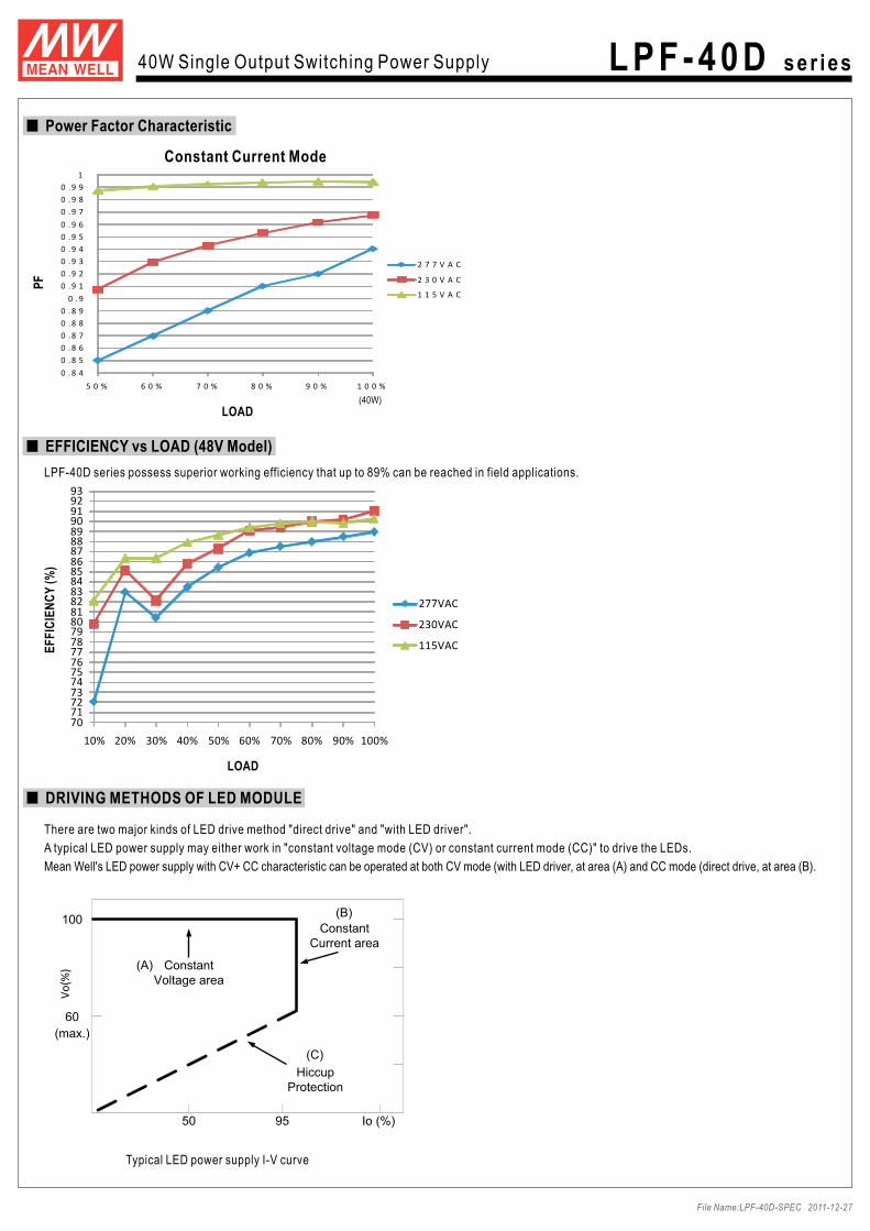
PF>0.97/115VAC, PF>0.95/230VAC, PF>0.92/277VAC at full load (Please refer to "Power Factor Characteristic" curve)
84% 85% 86% 87% 88% 88% 89%
COLD START 75A/230VAC
<0.75mA / 240VAC
95 ~ 108%
Protection type : Constant current limiting, recovers automatically after fault condition is removed
-40 ~ +70 (Refer to "Derating Curve")
20 ~ 95% RH non-condensing
-40 ~ +80 , 10 ~ 95% RH
0.03%/ (0 ~ 50 )
10 ~ 500Hz, 5G 12min./1cycle, period for 72min. each along X, Y, Z axes
394.9Khrs min. MIL-HDBK-217F (25 )
162.5*43*32mm (L*W*H)
!"#$%%#&'(')*+*(,#-./#,&*01'%%2#)*3+143*5#'(*#)*',6(*5#'+#789:$;#13&6+<#('+*5#%4'5#'35#7= 4>#')?1*3+#+*)&*('+6(*"7"#@1&&%*#A#341,*#'(*#)*',6(*5#'+#79BCD#4>#?'35E15+F#?2#6,13G#'#!7H#+E1,+*5#&'1(IE1(*#+*()13'+*5#E1+F#'#9"!6>#A#JK6>#&'('%%*%#0'&'01+4("8"#/4%*('30*#L#130%65*,#,*+#6&#+4%*('30*<#%13*#(*G6%'+143#'35#%4'5#(*G6%'+143"J"#;43,+'3+#06((*3+#4&*('+143#(*G143#1,#E1+F13#M9N#O!99N#('+*5#46+&6+#P4%+'G*"#/F1,#1,#+F*#,61+'?%*#4&*('+143#(*G143#>4(#QRS#(*%'+*5#'&&%10'+143,<#?6+#&%*',*
(*043>1()#,&*01'%#*%*0+(10'%#(*T61(*)*3+,#>4(#,4)*#,&*01>10#,2,+*)#5*,1G3"="#S*('+13G#)'2#?*#3**5*5#635*(#%4E#13&6+#P4%+'G*,"#U%*',*#0F*0V#+F*#,+'+10#0F'('0+*(1,+10,#>4(#)4(*#5*+'1%,"M"#W61+'?%*#>4(#13544(#6,*#4(#46+544(#6,*#E1+F46+#51(*0+ ,63%1GF+#*X&4,6(*"#U%*',*#'P415#1))*(,*#13#+F*#E'+*(#4P*(#89#)136+*,"K"#Q*3G+F#4>#,*+#6&#+1)*#1,#)*',6(*5#'+#04%5#>1(,+#,+'(+"#/6(313G#.-Y.ZZ#+F*#&4E*(#,6&&%2#)'2#%*'5#+4#130(*',*#4>#+F*#,*+#6&#+1)*"["#/F*#&4E*(#,6&&%2#1,#043,15*(*5#',#'#04)&43*3+#+F'+#E1%%#?*#4&*('+*5#13#04)?13'+143#E1+F#>13'%#*T61&)*3+"#W130*#RB;#&*(>4()'30*#E1%%#?*#'>>*0+*5#?2#+F*
04)&%*+*#13,+'%%'+143<#+F*#>13'%#*T61&)*3+#)'36>'0+6(*(,#)6,+#(*IT6'%1>2#RB;#S1(*0+1P*#43#+F*#04)&%*+*#13,+'%%'+143#'G'13"
0.45Kg; 32pcs/15.4Kg/0.93CUFT
Protection type : Shut down and latch off o/p voltage, re-power on to recover
RIPPLE & NOISE (max.) Note.2
VOLTAGE TOLERANCE Note.3
ENVIRONMENT
SAFETY &
EMC
PROTECTION
90 10 (RTH2)
Protection type : Shut down o/p voltage, re-power on to recover
SHORT CIRCUIT Hiccup mode, recovers automatically after fault condition is removed.
UL8750, , J61347-1, J61347-2-13, IP67 approvedEN61347-1, EN61347-2-13 independent ; Design refer to UL60950-1, TUV EN60950-1
54V
32.4 ~ 54V
0.76A
41.04W
350mVp-p
4.0%
0.5%
0.5%
42V
25.2 ~ 42V
0.96A
40.32W
250mVp-p
4.0%
0.5%
0.5%
88.5% 89%
15 ~ 17V 17.5 ~ 21V 23 ~ 27V 28 ~ 35V 34 ~ 40V 41 ~ 49V 54 ~ 63V
0.6A / 115VAC 0.3A / 230VAC
46 ~ 54V 59 ~ 66V
File Name:LPF-40D-SPEC 2011-12-27
40W Single Output Switching Power Supply
\31P*(,'%#$;#13&6+#Y#Z6%%#('3G*
]61%+I13#'0+1P*#UZ;#>630+143
C1GF#*>>101*302#6&#+4#[^N
U(4+*0+143,L#WF4(+#01(061+#Y#.P*(#06((*3+#Y#.P*(#P4%+'G*#Y#.P*(#+*)&*('+6(*
;44%13G#?2#>(**#'1(#043P*0+143
51))13G#>630+143#_!O!9:50#4(#U`B#,1G3'%#4(#(*,1,+'30*a
W61+'?%*#>4(#QRS#%1GF+13G#'35#)4P13G#,1G3#'&&%10'+143,
;4)&%1'30*#+4#E4(%5E15*#,'>*+2#(*G6%'+143,#>4(#%1GF+13G
8#2*'(,#E'(('3+2
_6&#+4#89=:$;a
W61+'?%*#>4(#5(2#Y#5')&#Y#E*+#%40'+143,
Z6%%2#1,4%'+*5#&%',+10#0',*
Z6%%2#*30'&,6%'+*5#E1+F#bUMK#%*P*%#_-4+*"Ma
;%',, &4E*(#631+<#34#Zc
]61%+I13#8#13#!
Z*'+6(*,#L
LPF-40D ser ies
ISOLATION RESISTANCE
CONSTANT CURRENT REGION Note.4
SAFETY STANDARDS Note.6
WITHSTAND VOLTAGE I/P-O/P:3.75KVAC
I/P-O/P:100M Ohms / 500VDC / 25 / 70% RH
EMC IMMUNITY
Compliance to EN55015, EN61000-3-2 Class C ( 60% load) ; EN61000-3-3
Compliance to EN61000-4-2,3,4,5,6,8,11; EN61547, EN55024, light industry level(surge 2KV), criteria A
EMC EMISSION
IP67! " "##$%&'( _#>4(#J[:<=J:#43%2a _#*X0*&+#>4(#J[:<=J:#a

Mechanical Specification Case No.LPF-60B Unit:mm
LO
AD
(%)
20
40
60
80
100
INPUT VOLTAGE (V) 60Hz
90 100 125 135 145 155 165 175 180 200 230 305
100
90
80
70
60
50
40
LO
AD
(%)
Derating Curve
LO
AD
(%)
Derating Curve Static Characteristics
AMBIENT TEMPERATURE ( )
LO
AD
(%)
175
LO
AD
(%)
(HORIZONTAL)-30 0 15 300 40 50-40 60 70
DIM+DIM-
3.6
3.5
3.5
3.6
3.5
3.5SJTW 18AWG 2C
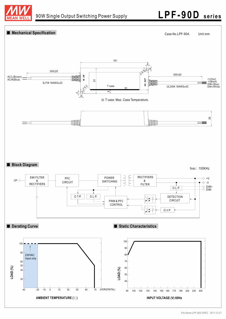
T case: Max. Case Temperature.
43 60T case
13
32
AC/L(Brown)AC/N(Blue)
300 20300 20
162.5
+V(Red)
DIM+(Blue)-V(Black)
DIM-(White)UL2464 18AWG 2C(+V,-V)UL2464 22AWG 2C(DIM+,DIM-)
40W Single Output Switching Power Supply LPF-40D ser ies
File Name:LPF-40D-SPEC 2011-12-27
Fosc : 100KHz
DETECTIONPWM & PFC CIRCUIT
O.L.P.
EMI FILTER
RECTIFIERS
POWERSWITCHING
FILTER&
RECTIFIERS +V
-VI/P
CONTROL
O.V.P.
&
O.L.P.
PFC
CIRCUIT
Block Diagram
707172737475767778798081828384858687888990919293
10% 20% 30% 40% 50% 60% 70% 80% 90% 100%
277VAC
230VAC
115VAC
0 . 8 4
0 . 8 5
0 . 8 6
0 . 8 7
0 . 8 8
0 . 8 9
0 . 9
0 . 9 1
0 . 9 2
0 . 9 3
0 . 9 4
0 . 9 5
0 . 9 6
0 . 9 7
0 . 9 8
0 . 9 9
1
5 0 % 6 0 % 7 0 % 8 0 % 9 0 % 1 0 0 %
2 7 7 V A C
2 3 0 V A C
1 1 5 V A C
LPF-40D series possess superior working efficiency that up to 89% can be reached in field applications.
LOAD
EF
FIC
IEN
CY
(%)
EFFICIENCY vs LOAD (48V Model)
PF
LOAD
Constant Current Mode
There are two major kinds of LED drive method "direct drive" and "with LED driver".
Typical LED power supply I-V curve
A typical LED power supply may either work in "constant voltage mode (CV) or constant current mode (CC)" to drive the LEDs.
Mean Well's LED power supply with CV+ CC characteristic can be operated at both CV mode (with LED driver, at area (A) and CC mode (direct drive, at area (B).
DRIVING METHODS OF LED MODULE
Vo
(%)
100
60
50 95
(max.)
Io (%)
ConstantVoltage area
ConstantCurrent area
HiccupProtection
(A)
(B)
(C)
(40W)
Power Factor Characteristic
40W Single Output Switching Power Supply LPF-40D ser ies
File Name:LPF-40D-SPEC 2011-12-27

Dimming connection diagram for turning the lighting fixture ON/OFF :
Using a switch and relay can turn ON/OFF the lighting fixture.
Using the built-in dimming function on LPF-40D can't turn the lighting fixture totally dark. Please refer to the connection method below to
achieve 0% brightness of the lighting fixture connecting to the LED power supply unit.
1.Output constant current level can be adjusted through output cable by connecting a resistor or 1~10Vdc or 10V PWM signal between DIM+ and DIM-.
2.The LED lighting fixture can be turned ON/OFF by the switch.
N L
LED Lighting Fixture
Relay
Blue
BrownAC/L
AC/NLPF-40D
LPF-40D
DIM+DIM-
V(-)V(+)
Blue
White
BlackRed
Switch Adjuster
0~100K Ohms resistance
1~10V DC Voltage
10V PWM Signal
DIMMING OPERATION
AC/N(Blue)
AC/L(Brown)+V(Red)-V(Black)DIM+(Blue)DIM-(White)
60K
60%
60%
10K
1V 4V 7V2V 5V 8V3V 6V 9V 10V
10%
10%
20K
20%
20%
30K
30%
30%
40K
40%
40%
50K
50%
50%
70K
70%
70%
80K
80%
80%
90K 100K OPEN
OPEN
OPEN
90%
90%
100% 100%~108%
100%~108%
100%~108%
100%
Resistance value
Dimming value
Output current
Output current
1 ~ 10V dimming function for output current adjustment (Typical)
60%
60%
10%
10%
20%
20%
30%
30%
40%
40%
50%
50%
70%
70%
80%
80%
90%
90%
100%
100%Duty value
Output current
Reference resistance value for output current adjustment (Typical)
Built-in 3 in 1 dimming function, o 10V PWM signal or resistanceutput constant current level can be adjusted through output cable by 1 ~ 10Vdc,
between DIM+ and DIM-.
Please DO NOT connect "DIM-" to "-V".
10V PWM signal for output current adjustment (Typical): Frequency range :100Hz ~ 3KHz
40W Single Output Switching Power Supply LPF-40D ser ies
File Name:LPF-40D-SPEC 2011-12-27

SPECIFICATIONMODEL
DC VOLTAGE
RATED CURRENT
RATED POWER
OUTPUT
LINE REGULATION
LOAD REGULATION
SETUP, RISE TIME Note.7
HOLD UP TIME (Typ.)
VOLTAGE RANGE Note.5
FREQUENCY RANGE
POWER FACTOR (Typ.)
EFFICIENCY (Typ.)
AC CURRENT (Typ.)
INPUT
INRUSH CURRENT (Typ.)
LEAKAGE CURRENT
SAFETY STANDARDS Note.6
WORKING TEMP.
WORKING HUMIDITY
STORAGE TEMP., HUMIDITY
TEMP. COEFFICIENT
VIBRATION
MTBF
DIMENSIONOTHERS
NOTE
PACKING
OVER CURRENT Note.4
OVER VOLTAGE
OVER TEMPERATURE
12V
7.2 ~12V
15V
9 ~ 15V
20V
12 ~ 20V
24V
14.4 ~ 24V
30V
18 ~ 30V
36V
21.6 ~ 36V
48V
28.8 ~ 48V
5A 4A 3A 2.5A 2A 1.67A 1.25A
60W 60W 60W 60W 60W 60.12W 60W
150mVp-p 150mVp-p 150mVp-p 150mVp-p 200mVp-p 250mVp-p 250mVp-p
4.0% 4.0% 4.0% 4.0% 4.0% 4.0% 4.0%
0.5% 0.5% 0.5% 0.5% 0.5% 0.5% 0.5%
2.0% 1.5% 1.0% 0.5% 0.5% 0.5% 0.5%
1000ms, 80ms / 115VAC at full load 1000ms, 80ms / 230VAC
16ms/230VAC 16ms/115VAC at full load
90 ~ 305VAC 127 ~ 431VDC
47 ~ 63Hz
PF>0.97/115VAC, PF>0.95/230VAC, PF>0.92/277VAC at full load (Please refer to "Power Factor Characteristic" curve)
86% 87% 88% 89% 90% 90% 90%
COLD START 75A/230VAC
<0.75mA / 240VAC
95 ~ 108%
Protection type : Constant current limiting, recovers automatically after fault condition is removed
-40 ~ +70 (Refer to "Derating Curve")
20 ~ 95% RH non-condensing
-40 ~ +80 , 10 ~ 95% RH
0.03%/ (0 ~ 50 )
10 ~ 500Hz, 5G 12min./1cycle, period for 72min. each along X, Y, Z axes
396.7Khrs min. MIL-HDBK-217F (25 )
162.5*43*32mm (L*W*H)
!"#$%%#&'(')*+*(,#-./#,&*01'%%2#)*3+143*5#'(*#)*',6(*5#'+#789:$;#13&6+<#('+*5#%4'5#'35#7= 4>#')?1*3+#+*)&*('+6(*"7"#@1&&%*#A#341,*#'(*#)*',6(*5#'+#79BCD#4>#?'35E15+F#?2#6,13G#'#!7H#+E1,+*5#&'1(IE1(*#+*()13'+*5#E1+F#'#9"!6>#A#JK6>#&'('%%*%#0'&'01+4("8"#/4%*('30*#L#130%65*,#,*+#6&#+4%*('30*<#%13*#(*G6%'+143#'35#%4'5#(*G6%'+143"J"#;43,+'3+#06((*3+#4&*('+143#(*G143#1,#E1+F13#M9N#O!99N#('+*5#46+&6+#P4%+'G*"#/F1,#1,#+F*#,61+'?%*#4&*('+143#(*G143#>4(#QRS#(*%'+*5#'&&%10'+143,<#?6+#&%*',*
(*043>1()#,&*01'%#*%*0+(10'%#(*T61(*)*3+,#>4(#,4)*#,&*01>10#,2,+*)#5*,1G3"="#S*('+13G#)'2#?*#3**5*5#635*(#%4E#13&6+#P4%+'G*,"#U%*',*#0F*0V#+F*#,+'+10#0F'('0+*(1,+10,#>4(#)4(*#5*+'1%,"M"#W61+'?%*#>4(#13544(#6,*#4(#46+544(#6,*#E1+F46+#51(*0+ ,63%1GF+#*X&4,6(*"#U%*',*#'P415#1))*(,*#13#+F*#E'+*(#4P*(#89#)136+*,"K"#Q*3G+F#4>#,*+#6&#+1)*#1,#)*',6(*5#'+#04%5#>1(,+#,+'(+"#/6(313G#.-Y.ZZ#+F*#&4E*(#,6&&%2#)'2#%*'5#+4#130(*',*#4>#+F*#,*+#6&#+1)*"["#/F*#&4E*(#,6&&%2#1,#043,15*(*5#',#'#04)&43*3+#+F'+#E1%%#?*#4&*('+*5#13#04)?13'+143#E1+F#>13'%#*T61&)*3+"#W130*#RB;#&*(>4()'30*#E1%%#?*#'>>*0+*5#?2#+F*
04)&%*+*#13,+'%%'+143<#+F*#>13'%#*T61&)*3+#)'36>'0+6(*(,#)6,+#(*IT6'%1>2#RB;#S1(*0+1P*#43#+F*#04)&%*+*#13,+'%%'+143#'G'13"
0.45Kg; 32pcs/15.4Kg/0.93CUFT
Protection type : Shut down and latch off o/p voltage, re-power on to recover
60W Single Output Switching Power Supply
\31P*(,'%#$;#13&6+#Y#Z6%%#('3G*
]61%+I13#'0+1P*#UZ;#>630+143
C1GF#*>>101*302#6&#+4#^9N
U(4+*0+143,L#WF4(+#01(061+#Y#.P*(#06((*3+#Y#.P*(#P4%+'G*#Y#.P*(#+*)&*('+6(*
;44%13G#?2#>(**#'1(#043P*0+143
51))13G#>630+143#_!O!9:50#4(#U`B#,1G3'%#4(#(*,1,+'30*a
W61+'?%*#>4(#QRS#%1GF+13G#'35#)4P13G#,1G3#'&&%10'+143,
;4)&%1'30*#+4#E4(%5E15*#,'>*+2#(*G6%'+143,#>4(#%1GF+13G
8#2*'(,#E'(('3+2
_6&#+4#89=:$;a
W61+'?%*#>4(#5(2#Y#5')&#Y#E*+#%40'+143,
Z6%%2#1,4%'+*5#&%',+10#0',*
Z6%%2#*30'&,6%'+*5#E1+F#bUMK#%*P*%#_-4+*"Ma
;%',, &4E*(#631+<#34#Zc
]61%+I13#8#13#!
Z*'+6(*,#L
LPF-60D ser ies
RIPPLE & NOISE (max.) Note.2
VOLTAGE TOLERANCE Note.3
ENVIRONMENT
SAFETY &
EMC
PROTECTION
90 10 (RTH2)
Protection type : Shut down o/p voltage, re-power on to recover
SHORT CIRCUIT Hiccup mode, recovers automatically after fault condition is removed.
UL8750, , J61347-1, J61347-2-13, IP67 approvedEN61347-1, EN61347-2-13 independent ; Design refer to UL60950-1, TUV EN60950-1
54V
32.4 ~ 54V
1.12A
60.48W
350mVp-p
4.0%
0.5%
0.5%
42V
25.2 ~ 42V
1.43A
60.06W
250mVp-p
4.0%
0.5%
0.5%
90% 90%
15 ~ 17V 17.5 ~ 21V 23 ~ 27V 28 ~ 35V 34 ~ 40V 41 ~ 49V 54 ~ 63V
0.8A / 115VAC 0.4A / 230VAC
46 ~ 54V 59 ~ 66V
File Name:LPF-60D-SPEC 2011-12-27
LPF-60D-12 LPF-60D-15 LPF-60D-20 LPF-60D-24 LPF-60D-30 LPF-60D-36 LPF-60D-42 LPF-60D-48 LPF-60D-54
WITHSTAND VOLTAGE
ISOLATION RESISTANCE
I/P-O/P:3.75KVAC
I/P-O/P:100M Ohms / 500VDC / 25 / 70% RH
CONSTANT CURRENT REGION Note.4
IP67! " "##$%&'(
EMC IMMUNITY
Compliance to EN55015, EN61000-3-2 Class C ( 60% load) ; EN61000-3-3
Compliance to EN61000-4-2,3,4,5,6,8,11; EN61547, EN55024, light industry level(surge 2KV), criteria A
EMC EMISSION
_#>4(#J[:<=J:#43%2a _#*X0*&+#>4(#J[:<=J:#a

Mechanical Specification
LO
AD
(%)
INPUT VOLTAGE (V) 60Hz
90 100 125 135 145 155 165 175 180 200 230 305
100
90
80
70
60
50
40
LO
AD
(%)
Derating Curve
LO
AD
(%)
Derating Curve Static Characteristics
AMBIENT TEMPERATURE ( )
LO
AD
(%)
175
LO
AD
(%)
Case No.LPF-60B Unit:mm
DIM+DIM-
20
40
60
80
100
(HORIZONTAL)-30 0 15 300 40 50-40 60 70
230VACInput only
50
3.6
3.5
3.5
3.6
3.5
3.5SJTW 18AWG 2C
T case: Max. Case Temperature.
43 60T case
13
32
UL2464 18AWG 2C(+V,-V)UL2464 22AWG 2C(DIM+,DIM-)
AC/L(Brown)AC/N(Blue)
300 20300 20
162.5
+V(Red)
DIM+(Blue)-V(Black)
DIM-(White)
60W Single Output Switching Power Supply L PF - 60D ser ies
File Name:LPF-60D-SPEC 2011-12-27
Fosc : 100KHz
DETECTIONPWM & PFC CIRCUIT
O.L.P.
EMI FILTER
RECTIFIERS
POWERSWITCHING
FILTER&
RECTIFIERS +V
-VI/P
CONTROL
O.V.P.
&
O.L.P.
PFC
CIRCUIT
Block Diagram

0 . 8 4
0 . 8 5
0 . 8 6
0 . 8 7
0 . 8 8
0 . 8 9
0 . 9
0 . 9 1
0 . 9 2
0 . 9 3
0 . 9 4
0 . 9 5
0 . 9 6
0 . 9 7
0 . 9 8
0 . 9 9
1
5 0 % 6 0 % 7 0 % 8 0 % 9 0 % 1 0 0 %
2 7 7 V A C
2 3 0 V A C
1 1 5 V A C
78
79
80
81
82
83
84
85
86
87
88
89
90
91
92
93
10% 20% 30% 40% 50% 60% 70% 80% 90% 100%
277VAC
230VAC
115VAC
LOAD
EF
FIC
IEN
CY
(%)
LPF-60D series possess superior working efficiency that up to 90% can be reached in field applications.
EFFICIENCY vs LOAD (48V Model)
PF
LOAD
Constant Current Mode
There are two major kinds of LED drive method "direct drive" and "with LED driver".
Typical LED power supply I-V curve
A typical LED power supply may either work in "constant voltage mode (CV) or constant current mode (CC)" to drive the LEDs.
Mean Well's LED power supply with CV+ CC characteristic can be operated at both CV mode (with LED driver, at area (A) and CC mode (direct drive, at area (B).
DRIVING METHODS OF LED MODULE
Vo
(%)
100
60
50 95
(max.)
Io (%)
ConstantVoltage area
ConstantCurrent area
HiccupProtection
(A)
(B)
(C)
(60W)
Power Factor Characteristic
60W Single Output Switching Power Supply L PF - 60D ser ies
File Name:LPF-60D-SPEC 2011-12-27

Using a switch and relay can turn ON/OFF the lighting fixture.
1.Output constant current level can be adjusted through output cable by connecting a resistor or 1~10Vdc or 10V PWM signal between DIM+ and DIM-.
2.The LED lighting fixture can be turned ON/OFF by the switch.
N L
Relay
Blue
BrownAC/L
AC/NLPF-60D
DIM+DIM-
V(-)V(+)
Blue
White
BlackRed
Switch Adjuster
0~100K Ohms resistance
1~10V DC Voltage
10V PWM Signal
60K
60%
60%
10K
1V 4V 7V2V 5V 8V3V 6V 9V 10V
10%
10%
20K
20%
20%
30K
30%
30%
40K
40%
40%
50K
50%
50%
70K
70%
70%
80K
80%
80%
90K 100K OPEN
OPEN
OPEN
90%
90%
100% 100%~108%
100%~108%
100%~108%
100%
Resistance value
Dimming value
Output current
Output current
1 ~ 10V dimming function for output current adjustment (Typical)
60%
60%
10%
10%
20%
20%
30%
30%
40%
40%
50%
50%
70%
70%
80%
80%
90%
90%
100%
100%Duty value
Output current
Reference resistance value for output current adjustment (Typical)
Built-in 3 in 1 dimming function, o 10V PWM signal or resistanceutput constant current level can be adjusted through output cable by 1 ~ 10Vdc,
between DIM+ and DIM-.
Please DO NOT connect "DIM-" to "-V".
10V PWM signal for output current adjustment (Typical): Frequency range :100Hz ~ 3KHz
Dimming connection diagram for turning the lighting fixture ON/OFF :
Using the built-in dimming function on LPF-60D can't turn the lighting fixture totally dark. Please refer to the connection method below to
achieve 0% brightness of the lighting fixture connecting to the LED power supply unit.
LED Lighting Fixture
LPF-60DAC/N(Blue)
AC/L(Brown)+V(Red)-V(Black)DIM+(Blue)DIM-(White)
DIMMING OPERATION
60W Single Output Switching Power Supply L PF - 60D ser ies
File Name:LPF-60D-SPEC 2011-12-27

WITHSTAND VOLTAGE
ISOLATION RESISTANCE
I/P-O/P:3.75KVAC
I/P-O/P:100M Ohms / 500VDC / 25 / 70% RH
CONSTANT CURRENT REGION Note.4
SPECIFICATIONMODEL
DC VOLTAGE
RATED CURRENT
RATED POWER
OUTPUT
LINE REGULATION
LOAD REGULATION
SETUP, RISE TIME Note.7
HOLD UP TIME (Typ.)
VOLTAGE RANGE Note.5
FREQUENCY RANGE
POWER FACTOR (Typ.)
EFFICIENCY (Typ.)
AC CURRENT (Typ.)
INPUT
INRUSH CURRENT( .)Typ
LEAKAGE CURRENT
SAFETY STANDARDS
WORKING TEMP.
WORKING HUMIDITY
STORAGE TEMP., HUMIDITY
TEMP. COEFFICIENT
VIBRATION
MTBF
DIMENSIONOTHERS
NOTE
PACKING
OVER CURRENT Note.4
OVER VOLTAGE
OVER TEMPERATURE
16ms/230VAC 16ms/115VAC at full load
90 ~ 305VAC 127 ~ 431VDC
47 ~ 63Hz
COLD START 70A/230VAC
<0.75mA / 277VAC
95 ~ 108%
Protection type : Constant current limiting, recovers automatically after fault condition is removed
Compliance to EN55015, EN61000-3-2 Class C ( 60% load) ; EN61000-3-3
Compliance to EN61000-4-2,3,4,5,6,8,11; EN61547, EN55024, light industry level(surge 2KV), criteria A
20 ~ 95% RH non-condensing
-40 ~ +80 , 10 ~ 95% RH
0.03%/ (0 ~ 50 )
10 ~ 500Hz, 5G 12min./1cycle, period for 72min. each along X, Y, Z axes
267.2Khrs min. MIL-HDBK-217F (25 )
161*61*36mm (L*W*H)
!"#$%%#&'(')*+*(,#-./#,&*01'%%2#)*3+143*5#'(*#)*',6(*5#'+#789:$;#13&6+<#('+*5#%4'5#'35#7= 4>#')?1*3+#+*)&*('+6(*"7"#@1&&%*#A#341,*#'(*#)*',6(*5#'+#79BCD#4>#?'35E15+F#?2#6,13G#'#!7H#+E1,+*5#&'1(IE1(*#+*()13'+*5#E1+F#'#9"!6>#A#JK6>#&'('%%*%#0'&'01+4("8"#/4%*('30*#L#130%65*,#,*+#6&#+4%*('30*<#%13*#(*G6%'+143#'35#%4'5#(*G6%'+143"J"#;43,+'3+#06((*3+#4&*('+143#(*G143#1,#E1+F13#M9N#O!99N#('+*5#46+&6+#P4%+'G*"#/F1,#1,#+F*#,61+'?%*#4&*('+143#(*G143#>4(#QRS#(*%'+*5#'&&%10'+143,<#?6+#&%*',*(*043>1()#,&*01'%#*%*0+(10'%#(*T61(*)*3+,#>4(#,4)*#,&*01>10#,2,+*)#5*,1G3"
="#S*('+13G#)'2#?*#3**5*5#635*(#%4E#13&6+#P4%+'G*,"#U%*',*#0F*0V#+F*#,+'+10#0F'('0+*(1,+10,#>4(#)4(*#5*+'1%,"M"#W61+'?%*#>4(#13544(#6,*#4(#46+544(#6,*#E1+F46+#51(*0+ ,63%1GF+#*X&4,6(*"#U%*',*#'P415#1))*(,*#13#+F*#E'+*(#4P*(#89#)136+*,"K"#Q*3G+F#4>#,*+#6&#+1)*#1,#)*',6(*5#'+#04%5#>1(,+#,+'(+"#/6(313G#.-Y.ZZ#+F*#&4E*(#,6&&%2#)'2#%*'5#+4#130(*',*#4>#+F*#,*+#6&#+1)*"["#/F*#&4E*(#,6&&%2#1,#043,15*(*5#',#'#04)&43*3+#+F'+#E1%%#?*#4&*('+*5#13#04)?13'+143#E1+F#>13'%#*T61&)*3+"#W130*#RB;#&*(>4()'30*#E1%%#?*#'>>*0+*5#?2#+F*
04)&%*+*#13,+'%%'+143<#+F*#>13'%#*T61&)*3+#)'36>'0+6(*(,#)6,+#(*IT6'%1>2#RB;#S1(*0+1P*#43#+F*#04)&%*+*#13,+'%%'+143#'G'13"\"#S1(*0+#0433*0+13G#+4#QRS,#1,#,6GG*,+*5<#?6+#1,#34+#,61+'?%*#>4(#6,13G#'551+143'%#5(1P*(,"
0.7Kg; 20pcs/15Kg/0.73CUFT
Protection type : Shut down o/p voltage, re-power on to recover
90W Single Output Switching Power Supply
]31P*(,'%#$;#13&6+#Y#Z6%%#('3G*#^6&#+4#89=:$;_
`61%+I13#'0+1P*#UZ;#>630+143
C1GF#*>>101*302#6&#+4#\9"=N
U(4+*0+143,L#WF4(+#01(061+#Y#.P*(#06((*3+#Y#.P*(#P4%+'G*#Y#.P*(#+*)&*('+6(*
;44%13G#?2#>(**#'1(#043P*0+143
51))13G#>630+143#^!O!9:50#4(#UaB#,1G3'%#4(#(*,1,+'30*_
W61+'?%*#>4(#QRS#%1GF+13G#'35#)4P13G#,1G3#'&&%10'+143,
;4)&%1'30*#+4#E4(%5E15*#,'>*+2#(*G6%'+143,#>4(#%1GF+13G
8#2*'(,#E'(('3+2
W61+'?%*#>4(#5(2#Y#5')&#Y#E*+#%40'+143,
Z6%%2#1,4%'+*5#&%',+10#0',*
Z6%%2#*30'&,6%'+*5#E1+F#bUMK#%*P*%#^-4+*"M_
;%',, &4E*(#631+<#34#Zc
`61%+I13#8#13#!
Z*'+6(*,#L
LPF-90D ser i es
RIPPLE & NOISE (max.) Note.2
VOLTAGE TOLERANCE Note.3
ENVIRONMENT
SAFETY &
EMC
PROTECTION
90 10 (RTH2)
Protection type : Shut down o/p voltage, re-power on to recover
18 ~ 21V 23 ~ 27V 28 ~ 34V 34 ~ 38V 41 ~ 46V 54 ~ 60V47 ~ 53V 59 ~ 65V
89% 89.5% 90% 90.5% 90.5% 90.5%90.5% 90.5%
4.0% 4.0% 4.0% 4.0% 4.0% 4.0% 4.0% 4.0%
0.5% 0.5% 0.5% 0.5% 0.5% 0.5%
1.5%
2000ms, 200ms at 95% load 230VAC / 115VAC
1.0% 0.5% 0.5% 0.5% 0.5%
0.5%
0.5%
0.5%
0.5%
15V
LPF-90D-15 LPF-90D-20 LPF-90D-24 LPF-90D-30 LPF-90D-36 LPF-90D-42 LPF-90D-48 LPF-90D-54
20V 24V 30V 36V 48V
5A 4.5A 3.75A 3A 2.5A 1.88A
75W 90W 90W 90W 90W 90.24W
150mVp-p 150mVp-p 150mVp-p 200mVp-p 200mVp-p 200mVp-p
54V
1.67A
90.18W
200mVp-p
42V
2.15A
90.3W
200mVp-p
PF>0.97/115VAC, PF>0.96/230VAC, PF>0.95/277VAC at full load (Please refer to "Power Factor Characteristic" curve)
0.95A / 115VAC 0.5A / 230VAC 0.4A / 277VAC
UL8750, EN61347-1, EN61347-2-13 independent , IP67 approved ; Design refer to UL60950-1, TUV EN60950-1, J61347-1, J61347-2-13
9 ~ 15V 12 ~ 20V 14.4 ~ 24V 18 ~ 30V 21.6 ~ 36V 28.8 ~ 48V 32.4 ~ 54V25.2 ~ 42V
File Name:LPF-90D-SPEC 2011-12-27
EMC IMMUNITY
EMC EMISSION
^#*X0*&+#>4(#J[:<=J:#_IP67! " "##$%&'( ^#>4(#J[:<=J:#43%2_
-40 ~ +70 (Refer to "Derating Curve")
Mechanical Specification
DETECTION
PWM & PFC CIRCUIT
O.L.P.O.T.P.
EMI FILTER
RECTIFIERS
POWERSWITCHING
FILTER&
RECTIFIERS +V
-VI/P
CONTROL
O.V.P.
&
O.L.P.
PFC
CIRCUIT
fosc : 100KHz
+V(Red)
DIM+(Blue)-V(Black)
DIM-(White)
DIM+DIM-
T case: Max. Case Temperature.
T case91
9
Block Diagram
AMBIENT TEMPERATURE ( )
LO
AD
(%)
230VACInput only
-40 -25 0-10 15 30 50 60 70
20
40
50
60
80
100
(HORIZONTAL)
Derating Curve Static Characteristics
INPUT VOLTAGE (V) 60Hz
90 100 125 135 145 155 165 175 180 200 230 305
100
90
80
70
60
50
40
LO
AD
(%)
90W Single Output Switching Power Supply LPF-90D ser ies
File Name:LPF-90D-SPEC 2011-12-27
300 20300 20
36
SJTW 18AWG 2C
61
UL2464 18AWG 4C
AC/L(Brown)AC/N(Blue)
161
4.5
4.5
4
4
4
4
Case No.LPF-90A Unit:mm

78
79
80
81
82
83
84
85
86
87
88
89
90
91
92
10% 20% 30% 40% 50% 60% 70% 80% 90% 100%
277VAC
230VAC
115VAC
0 . 9 5
0 . 9 6
0 . 9 7
0 . 9 8
0 . 9 9
1
5 0 % 6 0 % 7 0 % 8 0 % 9 0 % 1 0 0 %
2 7 7 V A C
2 3 0 V A C
1 1 5 V A C
PF
LOAD
Constant Current Mode
LPF-90D series possess superior working efficiency that up to 90.5% can be reached in field applications.
LOAD
EF
FIC
IEN
CY
(%)
EFFICIENCY vs LOAD (48V Model)
DRIVING METHODS OF LED MODULE
(90W)
This LED power supply is suggested to work in constant current mode area (CC) to drive the LEDs.
Typical LED power supply I-V curve
Vo
(%)
100
60
50 95
(max.)
Io (%)
ConstantCurrent area
HiccupProtection
90W Single Output Switching Power Supply LPF-90D ser ies
File Name:LPF-90D-SPEC 2011-12-27
Power Factor Characteristic

Dimming connection diagram for turning the lighting fixture ON/OFF :
Using a switch and relay can turn ON/OFF the lighting fixture.
Using the built-in dimming function on LPF-90D can't turn the lighting fixture totally dark. Please refer to the connection method below to
achieve 0% brightness of the lighting fixture connecting to the LED power supply unit.
1.Output constant current level can be adjusted through output cable by connecting a or 1~10Vdc or 10V PWM signal between DIM+ and DIM-.resistance
2.The LED lighting fixture can be turned ON/OFF by the switch.
N L
LED Lighting Fixture
Relay
Blue
BrownAC/L
AC/NLPF-90D
LPF-90D
DIM+DIM-
V(-)V(+)
Blue
White
BlackRed
Switch Adjuster
0~100K Ohms resistance
1~10V DC Voltage
10V PWM Signal
DIMMING OPERATION
Please DO NOT connect "DIM-" to "-V".
60K
60%
10K
10K /N 20K /N 30K /N 40K /N 50K /N 60K /N 70K /N 80K /N 90K /N 100K /N
Single driver
Multiple drivers(N=driver quantity for synchronized
dimming operation)
10%
20K
20%
30K
30%
40K
40%
50K
50%
70K
70%
80K
80%
90K 100K OPEN
90% 100%
Resistancevalue
Percentage of rated current 102%~108%
-----
60%
1V 4V 7V2V 5V 8V3V 6V 9V 10V
10% 20% 30% 40% 50% 70% 80%
OPEN
OPEN
90% 100%
Dimming value
Percentage of rated current
IP67 rated. Output constant current level can be adjusted through output cable by connecting a resistance orBuilt-in 3 in 1 dimming function,
1 ~ 10Vdc or 10V PWM signal between DIM+ and DIM-.
Reference resistance value for output current adjustment (Typical)
1 ~ 10V dimming function for output current adjustment (Typical)
60%
60%
10%
10%
20%
20%
30%
30%
40%
40%
50%
50%
70%
70%
80%
80%
90%
90%
100%
100%Duty value
Percentage of rated current
10V PWM signal for output current adjustment (Typical): Frequency range:100Hz ~ 3KHz
102%~108%
102%~108%
+V(Red)
DIM+(Blue)-V(Black)
DIM-(White)
AC/L(Brown)AC/N(Blue)
90W Single Output Switching Power Supply LPF-90D ser ies
File Name:LPF-90D-SPEC 2011-12-27