lpc8 ecu reference manual2. wiring 2.1. pin-outs and description 2.1.4 connector c pin-out pin i/o...
TRANSCRIPT

LPC8 ECU
-
REFERENCE MANUAL
Baldur Gíslason
September 22, 2019
Contents
1 Introduction 3
2 Wiring 42.1 Pin-outs and description . . . . . . . . . . . . . . . 4
2.1.1 Pin numbering . . . . . . . . . . . . . . . . 42.1.2 Connector A pin-out . . . . . . . . . . . . . 62.1.3 Connector B pin-out . . . . . . . . . . . . . 72.1.4 Connector C pin-out . . . . . . . . . . . . . 82.1.5 Connector D pin-out . . . . . . . . . . . . . 9
2.2 Wiring diagrams . . . . . . . . . . . . . . . . . . . 102.3 Wiring guidelines . . . . . . . . . . . . . . . . . . . 12
2.3.1 Grounding . . . . . . . . . . . . . . . . . . . 12
1

Contents Contents
2.3.2 Engine speed sensors . . . . . . . . . . . . . 122.3.3 Ignition outputs . . . . . . . . . . . . . . . . 122.3.4 Idle control . . . . . . . . . . . . . . . . . . 132.3.5 Electronic throttle control . . . . . . . . . . 132.3.6 Lambda sensor . . . . . . . . . . . . . . . . 132.3.7 Programmable outputs . . . . . . . . . . . . 14
3 Software conguration 153.1 Crank/cam trigger conguration . . . . . . . . . . . 15
3.1.1 Basic trigger . . . . . . . . . . . . . . . . . . 163.1.2 Versatile multi tooth decoder . . . . . . . . 173.1.3 Dual edge trigger . . . . . . . . . . . . . . . 203.1.4 Duty cycle coded trigger . . . . . . . . . . . 203.1.5 Equal spacing missing tooth . . . . . . . . . 21
3.2 Internal data logging . . . . . . . . . . . . . . . . . 213.3 Performing rmware upgrades . . . . . . . . . . . . 22
A Real time data elds 24
B Error codes 25
2

1 Introduction
LPC4 is an engine management system for spark ignition engines,capable of sequential fuel injection and ignition on 4 cylinderengines, bank re and waste spark or distributor spark on engineswith up to 8 cylinders. In addition to the more common fourstroke engines, two strokes and Wankel type engines are supportedas well.LPC8 is an evolution of the LPC4 that adds sequential fuellingand ignition for up to 8 cylinders as well as more sensor inputs,including but not limited to an integrated wide band lambdasensor controller for Bosch LSU sensors and inputs for two knocksensors. On the LPC8, internal data logging and real time clockis standard tment, but an option on the LPC4. The LPC8 alsohas electronic throttle control support standard while the LPC4requires an add-on board for that.It must be noted that many aspects of the conguration andstrategies are also documented inside the conguration le. Ifyou push F1 while editing a variable in the Calibrator application,you will get context sensitive help related to the category youare editing.
3

2 Wiring
2.1 Pin-outs and description
2.1.1 Pin numbering
(a) Connector A (b) Connector B
(c) Connector C (d) Connector D
Figure 2.1: Pin numbering of the dierent connectors on theback of the controller. Note that the connectors are not orientedas shown but the locking tabs face inwards.
4

2. Wiring 2.1. Pin-outs and description
5
2. Wiring 2.1. Pin-outs and description
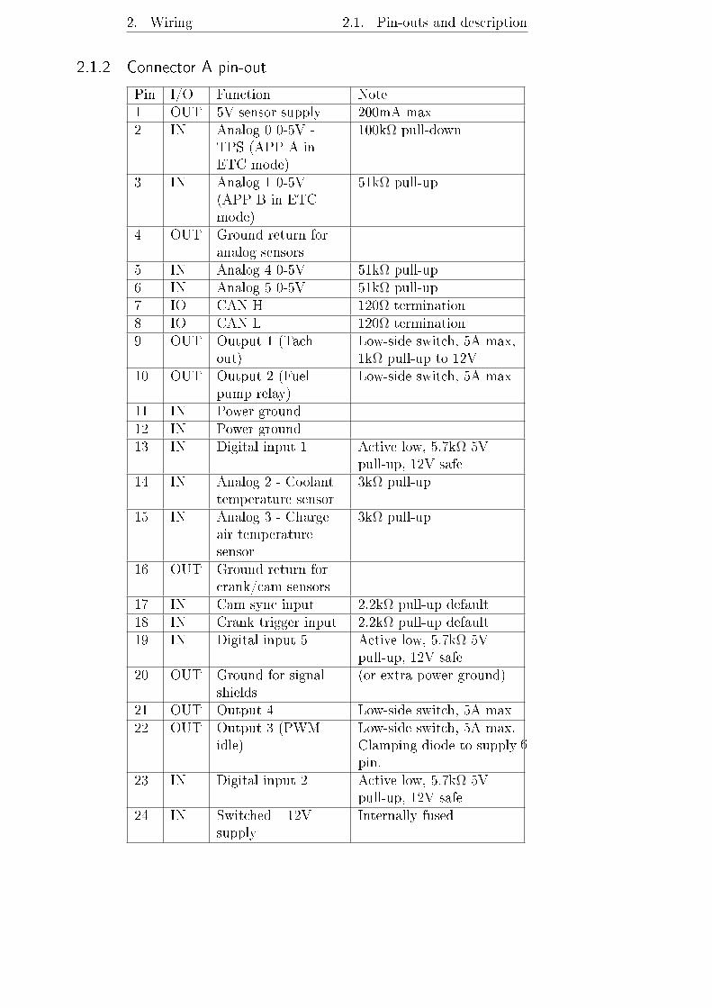
2.1.2 Connector A pin-out
Pin I/O Function Note1 OUT 5V sensor supply 200mA max2 IN Analog 0 0-5V -
TPS (APP A inETC mode)
100kΩ pull-down
3 IN Analog 1 0-5V(APP B in ETCmode)
51kΩ pull-up
4 OUT Ground return foranalog sensors
5 IN Analog 4 0-5V 51kΩ pull-up6 IN Analog 5 0-5V 51kΩ pull-up7 IO CAN H 120Ω termination8 IO CAN L 120Ω termination9 OUT Output 1 (Tach
out)Low-side switch, 5A max,1kΩ pull-up to 12V
10 OUT Output 2 (Fuelpump relay)
Low-side switch, 5A max
11 IN Power ground12 IN Power ground13 IN Digital input 1 Active low, 5.7kΩ 5V
pull-up, 12V safe14 IN Analog 2 - Coolant
temperature sensor3kΩ pull-up
15 IN Analog 3 - Chargeair temperaturesensor
3kΩ pull-up
16 OUT Ground return forcrank/cam sensors
17 IN Cam sync input 2.2kΩ pull-up default18 IN Crank trigger input 2.2kΩ pull-up default19 IN Digital input 5 Active low, 5.7kΩ 5V
pull-up, 12V safe20 OUT Ground for signal
shields(or extra power ground)
21 OUT Output 4 Low-side switch, 5A max22 OUT Output 3 (PWM
idle)Low-side switch, 5A max.Clamping diode to supplypin.
23 IN Digital input 2 Active low, 5.7kΩ 5Vpull-up, 12V safe
24 IN Switched +12Vsupply
Internally fused
6
2. Wiring 2.1. Pin-outs and description
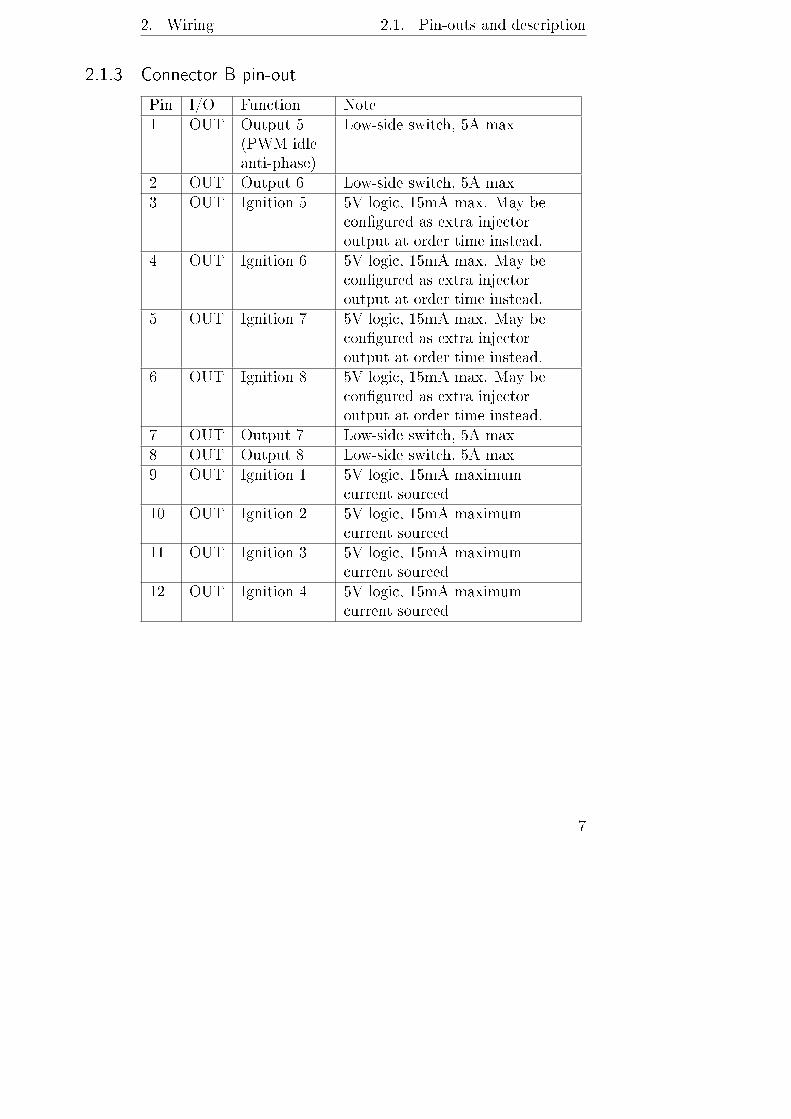
2.1.3 Connector B pin-out
Pin I/O Function Note1 OUT Output 5
(PWM idleanti-phase)
Low-side switch, 5A max
2 OUT Output 6 Low-side switch, 5A max3 OUT Ignition 5 5V logic, 15mA max. May be
congured as extra injectoroutput at order time instead.
4 OUT Ignition 6 5V logic, 15mA max. May becongured as extra injectoroutput at order time instead.
5 OUT Ignition 7 5V logic, 15mA max. May becongured as extra injectoroutput at order time instead.
6 OUT Ignition 8 5V logic, 15mA max. May becongured as extra injectoroutput at order time instead.
7 OUT Output 7 Low-side switch, 5A max8 OUT Output 8 Low-side switch, 5A max9 OUT Ignition 1 5V logic, 15mA maximum
current sourced10 OUT Ignition 2 5V logic, 15mA maximum
current sourced11 OUT Ignition 3 5V logic, 15mA maximum
current sourced12 OUT Ignition 4 5V logic, 15mA maximum
current sourced
7

2. Wiring 2.1. Pin-outs and description
2.1.4 Connector C pin-out
Pin I/O Function Note1 IN Knock sensor 12 IN Knock sensor 23 IN Lambda sensor
nernst voltageConnect to pin 6 of LSU4.9sensor (black wire)
4 OUT Lambda sensorvirtual ground
Connect to pin 2 of LSU4.9sensor (yellow wire)
5 IN Analog 10 0-5V 51kΩ 5V pull-up default,software selectable 2975 Ω
6 IN Analog 8 0-5V 51kΩ 5V pull-up. Throttleposition A when usingETC.
7 IN Analog 12 0-5V 51kΩ 5V pull-up.8 OUT Ground return for
analog sensors9 IN Digital input 4
(vehicle speedtypical)
Active low, 11kΩ 5Vpull-up, 12V safe
10 OUT Lambda sensorpump current
Connect to pin 1 of LSU4.9sensor (red wire)
11 IN Lambda sensortrim resistor
Connect to pin 5 of LSU4.9sensor (no wire)
12 IN Digital input 3 Active low, 11kΩ 5Vpull-up, 12V safe
13 IN Analog 11 0-5V 51kΩ 5V pull-up default,software selectable 2975 Ω
14 IN Analog 9 51kΩ 5V pull-up. Throttleposition B when using ETC.
15 NC NC Analog 15 if no internalbarometric pressure sensoris tted
16 OUT 5V sensor supply 200mA max, shared withother 5V outputs
8

2. Wiring 2.1. Pin-outs and description
2.1.5 Connector D pin-out
Pin I/O Function Note1 OUT Throttle
H bridgeoutput 1
Positive in forward (opening)direction. 15A max current
2 OUT Injector 1 Low-side switch, 5A max3 OUT Injector 2 Low-side switch, 5A max4 OUT Injector 3 Low-side switch, 5A max5 OUT Injector 4 Low-side switch, 5A max6 OUT Lambda
heaterLow-side switch, 5A max, connectto pin 3 of LSU4.9 sensor (whitewire)
7 IN Powerground
Join with wires from pins 11 and 12of connector A no more than150mm away from controller.
8 OUT ThrottleH bridgeoutput 2
Positive in reverse (closing)direction. 15A max current
9 OUT Injector 5 Low-side switch, 5A max10 OUT Injector 6 Low-side switch, 5A max11 OUT Injector 7 Low-side switch, 5A max12 OUT Injector 8 Low-side switch, 5A max13 IN +12V
supply forH bridge
Not protected, use external 15Afuse. Only connect if usingelectronic throttle.
14 IN Powerground
Join with wires from pins 11 and 12of connector A no more than150mm away from controller.
9

2. Wiring 2.2. Wiring diagrams
2.2 Wiring diagrams
Figure 2.2: Typical basic wiring
10
2. Wiring 2.2. Wiring diagrams
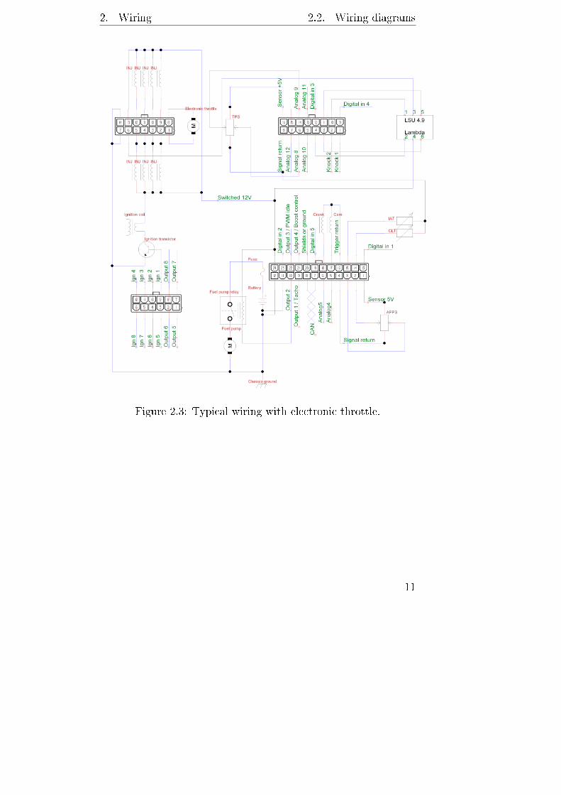
Figure 2.3: Typical wiring with electronic throttle.
11

2. Wiring 2.3. Wiring guidelines
2.3 Wiring guidelines
2.3.1 Grounding
The controller should be connected to the battery negative terminalor another reliable grounding point by at least a pair of 1.5mm2
wires or a single 6mm2 wire joined to smaller wires near theconnector. The controller requires 4 ground wires, connectedto pins 11 and 12 of connector A and pins 7 and 14 of connectorD. These 4 ground wires must be joined together no more than150mm away from the controller. From this joint you may connectthe ground wire(s) that go to the battery or cylinder head. Animproper ground connection will cause electrical noise and possiblyfaults with controller operation. If utilising factory wiring, joiningall of the supply ground wires for the original ECU should suce.
2.3.2 Engine speed sensors
The inputs on the controller for crank/cam sensors are of schmitttrigger logic type, with 2.2kΩ pull-ups and with over-/undervoltageprotection diodes. Thus they may be connected directly to open-collectoror logic sensors (Hall eect, optical) or variable reluctance sensors.Some poorly designed VR sensors have an output voltage toosmall at cranking speeds for reliable starting, for those an ampliermodule must be installed in the controller.
2.3.3 Ignition outputs
The LPC8 has eight 5V logic-level outputs current limited to15mA. To utilise those outputs requires either ignition coils withinternal igniters or an external ignition transistor module. Ifyour engine has neither, a good cost eective transistor modulefor up to 8 coils may be purchased from https://controls.is/
itm8.html
12

2. Wiring 2.3. Wiring guidelines
2.3.4 Idle control
The LPC8 supports three types of idle control valves. 2 wirePWM, 3 wire PWM and 6 wire stepper. 4 wire stepper canbe handled by tting pull-up resistors to each wire. A valueof 15Ω and 2W has been shown to work well on the commonGM/Chrysler valves. A 2 wire PWM valve must be connectedto output number 3. A 3 wire PWM valve uses outputs 3 and 5to drive each coil. Stepper valves can be connected to any of theoutputs but usually outputs 5 through 8 are used, arrangementof the wiring does not matter as it can be congured in software.When using electronic throttle control, a dedicated idle controlvalve is typically not necessary or desireable, but is supported bythe controller rmware nonetheless. If not using the electronicthrottle for idle control, simply set the idle control authority inthe electronic throttle section of the conguration to zero.
2.3.5 Electronic throttle control
In electronic throttle control mode, the accelerator pedal connectsto pins 1 through 4 on connector A and throttle position sensorson the throttle body connect to pins 6 and 14 on connector Cas well as shared sensor ground and sensor 5V supply. It is notrecommended to share the ground path or 5V feed for the acceleratorpedal with any other sensor.The electronic throttle motor connects to pins 1 and 8 of connectorD, in current direction that opens the throttle, positive voltagewill be supplied from pin 1 and negative from pin 8.The throttle driver bridge needs a +12V supply feed to pin 13of connector D. An in-line fuse rated 10-15A is recommended toprotect the circuit.
2.3.6 Lambda sensor
The LPC8 includes a controller for one wide band lambda sensor.Calibration is provided to run Bosch LSU 4.9 sensors but if youare able to create your own calibration data, other LSU sensorsas well as certain NTK sensors may be used.
13

2. Wiring 2.3. Wiring guidelines
For LSU4.9 sensors, no calibration is typically necessary as thesensor's trim resistor is used for reference.
LSU 4.9 pin Function1 Pump current, pin C10 on ECU, red wire2 Virtual ground, pin C4 on ECU, yellow wire3 Heater negative, pin D6 on ECU, white wire4 Heater positive, 12V power when ECU is powered, grey wire5 Reference resistor, pin C11 on ECU, terminated inside connector, no wire6 Nernst voltage, pin C3 on ECU, black wire
Figure 2.4: Bosch LSU4.9 sensor wiring
2.3.7 Programmable outputs
The ECU has eight programmable outputs and while all lowspeed functions are applicable to every output, some PWM functionshave dedicated outputs. This means that if those functions areused, they can only be assigned to the specied output. Outputs1, 3 and 4 provide high accuracy PWM capability, with eventstimed to the nearest microsecond and a maximum PWM frequencyof 2000Hz. Outputs 5 through 8 provide lower accuracy PWMcapability with microsecond timing but possible timing error ofindividual pulses up to 100 microseconds. Maximum frequencyon those outputs is 200Hz and although average error is on theorder of zero, due to the nature of these software driven outputsoccasional pulses may be out by as much as 100 microseconds.The exception is output 5 when in PWM idle anti phase mode,where it is driven at full 1 microsecond precision.
Function OutputTachometer output 1PWM idle control 3PWM idle anti-phase 5
Figure 2.5: Functions with dedicated outputs
14

3 Software conguration
Refer to BG calibrator manual for introduction to the software.The default conguration le has the following dened keyboardshortcuts:Key FunctionF5 Edit main fuel mapF6 Edit main ignition timing map
3.1 Crank/cam trigger conguration
The LPC4 and LPC8 ECUs have a unique way of dealing withcrank/cam trigger signals. This enables it to decode a largevariety of dierent trigger arrangements without needing thermware to specically support each arrangement. As a consequencethe conguration of the trigger inputs may seem confusing torst time users. To combat this, presets are provided for commoncongurations, see the presets dialog in the calibrator softwareand check if your engine is listed.In this chapter, the primary (or only) trigger is always referredto as the crank trigger, despite the possibility of the reluctor orshutter wheel being driven from the camshaft. The primary/camlter periods let the ECU ignore any event occurring within acertain amount of time since the previous event. Useful againstcertain types of noise in certain trigger arrangements. Mustbe set to a lower number than the shortest anticipated eventinterval at maximum engine operating speed.The modes of trigger input operation are as follows:
Basic Single impulse on crank trigger input for each cylinder'sring event. Works for congurations that only require a
15
3. Software conguration 3.1. Crank/cam trigger conguration
single ignition output, either single cylinder, multi cylinderwith distributor or multi cylinder running all cylinders inwaste spark conguration. Also useful if no ignition controlis required.
Versatile multi tooth The highly versatile crank/cam decoderfor variable reluctance type crank sensors or hall eectsetups where all the information required is available bydecoding only one type of signal edge (rising or falling, notboth).
Dual edge A variation of the versatile multi tooth decoderwhere alternating teeth dened are alternating polarity(rising or falling, starting with whichever is dened as thecrank trigger active edge).
Duty cycle coded A variation of the versatile multi toothdecoder that triggers on one edge type (rising or falling)but measures the duty cycle, the ratio between high andlow state. A pattern can then be entered denoting theduty cycle of past previous pulses and when that pattern ismatched, the decoder generates a sync event. This arrangementis used on the earlier generation GM LS type engine (24Xtrigger) but this mode can also be congured to decodesome Chrysler crank triggers.
Log only A mode that does not enable running an engine butdoes let one capture an event log of the crank/cam inputswithout fuel being injected or ignited.
3.1.1 Basic trigger
This mode has only three congurable options. The trigger angleoset whose useful range would be from zero up to the anglebetween ring events. (90 degrees on a 4 stroke V8 f.ex). Thecrank trigger active edge and the pulses skipped when startingoptions are also used. Cam sync, trigger teeth and other optionsnot used. Primary trigger lter period does apply.
16
3. Software conguration 3.1. Crank/cam trigger conguration
3.1.2 Versatile multi tooth decoder
The basic operating principle of the versatile multi tooth decoderis that each tooth sensed by the crank angle sensor is denedby the crank angle that separates it from the previous toothbefore it. The crank angle of the rst tooth in the cycle (akatrigger angle oset) in degrees before top dead centre cyl 1 isalso dened, cyl 1 being assumed to have an angle oset of zeroin the cylinder angle table. The trigger angle oset can have avalue of anywhere from zero to 719 degrees. Used in conjunctionwith the tooth gap table is also a tooth repeat table. The toothrepeat table saves the user from having to congure multipletooth entries where a number of adjacent teeth all have the samespacing. As an example a 36-1 crank trigger wheel only needstwo tooth entries. 20 degrees and 10 degrees, and in that casethe repeat values are 0 and 33 as the rst tooth of the 35 thatare present only occurs once, zero repetitions are performed.The second tooth and the 33 teeth that follow it have the sametooth spacing so a value of 33 is used for the second repeat value.From knowing the angle of the rst tooth and the spacing ofevery tooth from the previous one, the decoder can calculateengine speed as well as crank angle every time an event occurson the crank trigger input, but this information is not enough tolet the decoder nd its reference point in the cycle. To nd thereference point and start decoding from tooth one, there are anumber of strategies available. At the time of writing they are asfollows:
None In this mode, cam sync is relied upon entirely for crankangle reference. In this mode, there must be enough teethdened to cover the entire cycle so if there are 12 teeth onthe crank, the tooth cong must account for 24 teeth orsync is deemed lost before the next cam sync opportunity.
Missing tooth In this mode, the decoder compares the spacingof adjacent events and if the interval between events exceedsthe interval of the previous event by a congurable threshold(typically at least 1.5), the current event is deemed to betooth one and crank decoding can start. In this mode, the
17

3. Software conguration 3.1. Crank/cam trigger conguration
rst dened tooth must have its dened angle greater thanthe other teeth.
Extra tooth In this mode, the decoder compares the spacingof adjacent events and if the most recent interval is shorterthan the previous interval by a congurable threshold (typicallyno more than 0.7, preferrably less) then that tooth is ignoredand the next event following it is deemed tooth one anddecoding can start. There is a very good reason why theextra tooth is ignored in the code. For one, having extracrank angle resolution at one part of the cycle is of littlebenet, but if the exact angle of the extra tooth is notknown then it would be very detrimental to engine controlto include it in the decoder output. Therefore, in this mode,the extra tooth must not exist in the tooth denitions, therst tooth is the tooth following the extra tooth.
Two adjacent long gaps is used for 36-2-2-2 and similar congurationswhere the sync is found by detecting two adjacent gapsthat are wider. (One tooth, two missing, one tooth, twomissing again, for example.) In this strategy the sync thresholdratio is multiplied with the last tooth before the two biggaps, the previous two intervals must be bigger than theresult and the interval before the referenced interval mustalso be smaller than the result to register sync.
Double check missing tooth takes the last interval (beforethe current tooth), multiplies by the threshold and boththe current interval and the interval before the previousone must be shorter than the result. This is the recommendedmode to use for most 36-1 and 60-2 and similar triggers.Note that in this mode the rst tooth in the teeth table isthe second tooth after the gap in the trigger wheel.
If a cam position sensor is present, there are a number of dierentstrategies available to decode that. The behaviour of the camsync diers if a crank sync strategy is congured or not. Whena crank sync strategy is congured, the cam sync will not applyunless crank sync has been found, and when that happens the
18

3. Software conguration 3.1. Crank/cam trigger conguration
crank angle will be set to the correct phase according to theangle oset of crank tooth #1. If no crank sync strategy is selected,then the cam sync will apply immediately.The cam sync strategies are the following:
Cam state on crank sync This mode is useful for hall eector similar logic output cam position sensors with a singlewide tooth (half moon type). In this mode, the cam signalis not logged and no interrupts are generated on edge eventsbut instead the state of the cam signal is polled when acrank sync event happens (missing tooth, extra tooth).If the cam input is in a logic low state (less than 1 voltinput) then the congured angle oset is applied and fullsync mode is entered. If the cam input is in a logic highstate, then the congured angle oset is applied, shifted by360 degrees and full sync mode is entered.
Count cam impulses This mode is useful for all types of sensorsand applies to cam wheels with as little as a single toothbut also applies to more complex arrangements. In thismode, every event on the cam input increments a counterbut every event on the crank input reads the counter andresets it to zero. If the counter value matches the conguredcam sync count, then cam sync is applied at that crankevent and full sync mode is entered.An example where this mode is used is the Subaru 6/7pattern, where a series of two or three cam impulses canbe used to determine the crank angle and cam phase.
Count crank impulses This mode applies to certain crank/campatterns where there are two or more cam teeth unevenlyspaced or a greater number of evenly spaced cam teethwith some oddly spaced crank teeth. A counter is incrementedon every crank event but read and reset on every camevent. If the counter matches the congured cam synccount then the following crank event will apply the camsync. An example where this mode applies is Cosworth YBwhere the cam sync has two teeth spaced at 180 degrees ofcrank rotation.
19

3. Software conguration 3.1. Crank/cam trigger conguration
Primary trigger is cam This mode allows the use of a missingtooth or extra tooth trigger wheel rotating at cam speedso the reference tooth angle is correct and no extra camposition information is required for full sync operation.
Crank state on cam impulse This mode only applies to dual-edgetrigger decoder mode, used to decode DSM/Miata/Neontrigger. Has a congurable option for what the crank statemust be for the cam event to register. The crank eventfollowing the cam event is deemed tooth number one.
Cam count pattern Principally the same as count cam impulsesmode, except instead of comparing only the current valueof the counter every crank event, a congurable numberof previous values are also considered. This is useful if thecam wheel has an insane amount of oddly spaced teeth,such as seen on early Chrysler/Jeep 4.7 V8.
3.1.3 Dual edge trigger
A mode for logic type sensors only (hall eect or optical). Thismode is operationally identical to the versatile multi tooth triggerexcept that alternating teeth are expected to occur on alternatingedges, with the rst tooth occurring on the congured activeedge for the crank trigger. Examples that use this include theMitsubishi 4g63 and Mazda Miata, where it is used with camsync.
3.1.4 Duty cycle coded trigger
A mode for logic type sensors only (hall eect or optical). Thismode is operationally identical to the versatile multi tooth triggerexcept that the crank sync mode selector is not used. Insteadit is hard coded to use a duty cycle pattern to sync. Normaltrigger operation only happens on either a rising edge or a fallingedge and the period since the last opposite edge divided by theperiod since the last active edge is the duty cycle. In the pattern,a value of 1 matches a duty cycle greater than 50% and a valueof zero matches a duty cycle less than 50%. The pattern can
20
3. Software conguration 3.2. Internal data logging
have up to 8 positions. The typical use of this trigger mode isthe GM LS1 engine, where it allows reliable operation with orwithout cam sync.
3.1.5 Equal spacing missing tooth
This is a trigger mode that can be used interchangeably withversatile multi tooth on simple missing tooth setups (36-1 or60-2 for example), with the possibility of ignoring the teeth oneither side of the gap in the pattern if they prove to be imprecisein timing.
3.2 Internal data logging
The LPC8 controller includes 8GB or more logging memory aswell as a real time clock to time stamp the log les with timeand date of when logging started. Data recorded at the highestavailable logging rate (500Hz) will take up around 10 megabytesper minute. At the time of writing the download rate is around3 megabytes per minute so a 10 minute data log recorded at thehighest rate would take around 30 minutes to download fromthe controller. To keep log sizes small without compromising onlog resolution, burst mode is provided, where the logging ratecan be kept low normally but accelerated during conditions thatcommand it, such as when at full throttle.Data can only be downloaded when a log isn't being capturedand the engine isn't running. For that reason it is recommendedthat the controller is congured to not start recording until enginespeed reaches some non-zero number, except for testing of thelogging function itself. Once logging is started, it will continueuntil the controller is powered o or a stop condition is triggered.It is important to note that the binary format of the log leschanges when the rmware is updated, so old logs can be downloadedbut will not convert correctly to bglog format when the congurationle open in the Calibrator application does not match the rmwarethat recorded the log.
21
3. Software conguration 3.3. Performing rmware upgrades
3.3 Performing rmware upgrades
Whenever new features are introduced, new rmware becomesavailable for download at https://controls.is/firmware/.See the release notes if you are unsure of whether you shouldupdate or not. To perform a rmware upgrade:
1. Download rmware package from web site
2. Unzip rmware package into a directory on your hard drive
3. Connect USB cable between ECU and PC.
4. Power on ECU, do not start engine.
5. If you do not have the conguration backed up, run BGCalibrator, read conguration from ECU and save to le.This step may be skipped if you are performing the upgradeon an ECU you haven't made any previous congurationchanges to.
6. Run upgrade.cmd in directory where rmware les arelocated.
7. Wait until the upgrade application nishes, should be onthe order of 10 seconds.
8. Power ECU o.
9. Do not power ECU back on until you are ready to uploadconguration to it.
The ECU has been upgraded but now contains invalid conguration.If you are proceeding with default conguration, simply open thedefault conguration le for the new rmware in BG calibratorand go on-line, then send local settings when prompted aboutwhat to do with the ECU side conguration. Otherwise, if youwish to retain your previous conguration, which is generallyrecommended, perform the following steps:
1. Run the BG Calibrator software
22
3. Software conguration 3.3. Performing rmware upgrades
2. Open your old conguration le
3. Select File -> Convert configuration from the menubar.
4. Select the conguration included with the new rmware inthe le dialog.
5. The conguration has now been converted to the new format,save it and exit the Calibrator software.
6. Run the Calibrator software again and open the congurationle you saved previously, choose to work o-line.
7. Review the settings and verify that they make sense, seerelease notes for information about what settings may needrevisiting.
8. Go on-line and power on the ECU. Do not start engine.
9. When prompted, select to use local settings, which willthen be uploaded to the ECU.
After the conguration has been sent to the ECU and Calibratorapplication becomes responsive again, power the ECU o andthen back on. Now you can start the engine.
23

A Real time data elds
The descriptions of all the real time data elds have been movedinto the conguration le as of rmware version 1.15. They canbe read in the dialog for conguring the real time display orexported to a text document from Calibrator.
24
B Error codes
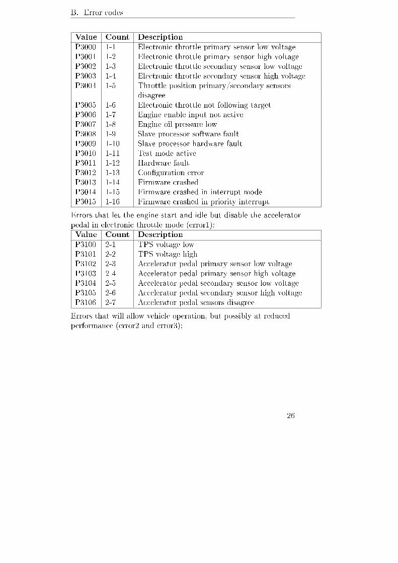
The error codes are stored on four bit masks, error0, error1,error2 and error3. They can be read using the Calibrator application(Communication -> View controller errors in on-line mode,Tools -> Decode error variables in log view mode). It isalso possible to read the errors using an OBD2 scan tool if OBD2connector is wired and OBD2 communications are enabled in theconguration. OBD2 DTC codes take the form of P3XZZ whereX is the error variable, 0 for error0 and so on and ZZ is the bitoset in that variable, starting with 00. Note that these codesdo not correspond with any auto manufacturer's codes.As of rmware 2.0 it is also possible to congure the check enginelamp to ash when error codes are present. The lamp will alternatebetween slow and fast ash rate, with the number of slow pulsespreceding the number of fast pulses. For example, four slowashes succeeded by a single fast ash signies low battery voltage.In the following error code tables, the second column shows thenumber of ashes associated with each error code.
Errors that prohibit engine starting (error0):
25
B. Error codes
Value Count Description
P3000 1-1 Electronic throttle primary sensor low voltageP3001 1-2 Electronic throttle primary sensor high voltageP3002 1-3 Electronic throttle secondary sensor low voltageP3003 1-4 Electronic throttle secondary sensor high voltageP3004 1-5 Throttle position primary/secondary sensors
disagreeP3005 1-6 Electronic throttle not following targetP3006 1-7 Engine enable input not activeP3007 1-8 Engine oil pressure lowP3008 1-9 Slave processor software faultP3009 1-10 Slave processor hardware faultP3010 1-11 Test mode activeP3011 1-12 Hardware faultP3012 1-13 Conguration errorP3013 1-14 Firmware crashedP3014 1-15 Firmware crashed in interrupt modeP3015 1-16 Firmware crashed in priority interrupt
Errors that let the engine start and idle but disable the acceleratorpedal in electronic throttle mode (error1):Value Count Description
P3100 2-1 TPS voltage lowP3101 2-2 TPS voltage highP3102 2-3 Accelerator pedal primary sensor low voltageP3103 2-4 Accelerator pedal primary sensor high voltageP3104 2-5 Accelerator pedal secondary sensor low voltageP3105 2-6 Accelerator pedal secondary sensor high voltageP3106 2-7 Accelerator pedal sensors disagree
Errors that will allow vehicle operation, but possibly at reducedperformance (error2 and error3):
26

B. Error codes
Value Count Description
P3200 3-1 MAP sensor voltage lowP3201 3-2 MAP sensor voltage highP3202 3-3 Coolant temp sensor open circuitP3203 3-4 Coolant temp sensor short circuitP3204 3-5 Air temp sensor open circuitP3205 3-6 Air temp sensor short circuitP3206 3-7 Lambda sensor voltage out of rangeP3207 3-8 Lambda sensor lack of activityP3208 3-9 Camshaft position sensor errorP3209 3-10 RTC battery fault or no RTC battery ttedP3210 3-11 Barometric pressure sensor low voltageP3211 3-12 Barometric pressure sensor high voltageP3212 3-13 EMAP sensor low voltageP3213 3-14 EMAP sensor high voltageP3214 3-15 MAP signal implausibleP3215 3-16 Engine coolant temperature too highP3216 4-1 Supply voltage too lowP3217 4-2 Supply voltage too highP3218 4-3 Charge air temperature too highP3219 4-4 Overboost protection triggeredP3220 4-5 Fuel pressure sensor low valueP3221 4-6 Fuel pressure sensor high valueP3222 4-7 Loss of CAN input dataP3223 4-8 Fuel pressure lowP3224 4-9 Fuel pressure highP3225 4-10 Engine coolant temperature implausibleP3226 4-11 VVT primary cam o targetP3227 4-12 VVT secondary cam o targetP3228 4-13 Lambda reading too leanP3229 4-14 Lambda reading too richP3230 4-15 MAF input low valueP3231 4-16 MAF input high value
27

B. Error codes
Value Count Description
P3300 5-1 Lambda sensor 2 voltage out of rangeP3301 5-2 Lambda sensor 2 lack of activityP3302 5-3 Lambda 2 reading too leanP3303 5-4 Lambda 2 reading too richP3304 5-5 N2O run aborted by low fuel pressureP3305 5-6 Oil pressure sensor low valueP3306 5-7 Oil pressure sensor high valueP3307 5-8 Oil temperature sensor low valueP3308 5-9 Oil temperature sensor high valueP3309 5-10 VVT cam 3 o targetP3310 5-11 VVT cam 4 o targetP3311 5-12 Post compressor pressure sensor low valueP3312 5-13 Post compressor pressure sensor high valueP3313 5-14 Post restrictor pressure sensor low valueP3314 5-15 Post restrictor pressure sensor high valueP3315 5-16 Transmission temperature sensor low valueP3316 6-1 Transmission temperature sensor high valueP3317 6-2 User dened error 1P3318 6-3 User dened error 2P3319 6-4 User dened error 3P3320 6-5 User dened error 4P3321 6-6 Injector duty cycle exceeded maximumP3322 6-7 Knock sensor 1 low input signalP3323 6-8 Knock sensor 2 low input signalP3324 6-9 Excessive knock detectedP3325 6-10 Fuel temperature sensor low input valueP3326 6-11 Fuel temperature sensor high input valueP3327 6-12 Fuel composition sensor low input valueP3328 6-13 Fuel composition sensor high input valueP3329 6-14 Mass air ow sensor signal implausible
28