lp-abr10 series setup / operation manual - pulsar · 3 safety notices . this product is intended...
TRANSCRIPT

2016.4 panasonic.net/id/pidsx/global
ME-LPABR10-SO-2
Please read these instructions carefully before using this product, and save this manual for future use.
Code Reader
Setup /
Operation Manual
LP-ABR10 Series

2
PrefaceThank you for purchasing our product.For full use of this product safely and properly, please read this manual carefully.This product has been strictly checked and tested prior to its delivery. However, please make sure that this product operates properly before using it. In case that the product becomes damaged or does not operate as specified in this manual, contact the dealer you purchased from or our sales office.
� General terms and conditions of this manual1. Before using this product, or before every starting operation, please confirm the correct functioning and performance
of this product.2. Contents of this manual could be changed without notice.3. This manual must not be partially or totally copied or revised.4. All efforts have been made to ensure the accuracy of all information in this manual. If there are any questions,
mistakes, or comments in this manual, please notify us.5. Please remind that we assume no liability for any results arising out of operations regardless of the above clauses.
� DisclaimerThe applications described in this manual are all intended for examples only. The purchase of our products described in this manual shall not be regarded as granting of a license to use our products in the described applications. We do NOT warrant that we have obtained some intellectual properties, such as patent rights, with respect to such applications, or that the described application may not infringe any intellectual property rights, such as patent rights, of a third party.
� Trademark• Windows is a registered trademark or trademark of Microsoft Corporation in the United States and/or other countries.• All other product names and companies provided in this manual are trademarks or registered trademarks of their
respective companies.
Cautions in HandlingTo reduce the risk of injury, loss of life, electric shock, fire, malfunction, and damage to equipment or property, always observe the following safety precautions.
The following symbols are used to classify and describe the level of hazard, injury, and property damage caused when the denotation is disregarded and improper use is performed.
WARNING Denotes a potential hazard that could result in serious injury or death.
CAUTION Denotes a hazard that could result in minor injury.
The following symbols are used to classify and describe the type of instructions to be observed.
This symbol is used to alert users to a specific operating procedure that must not be performed.
This symbols is used to alert users to a specific operating procedure that must be followed in order to operate the unit safely.
This symbols is used to alert users to a specific operating procedure that must be performed carefully.
ALWAYS FOLLOW THESE IMPORTANT SAFETY PRECAUTIONS!

3
Safety notices
This product is intended for use in general electronics equipment (electronic
computer, OA equipment, communications equipment, test and measurement
equipment, machine tools, industrial robots, AV equipment, home appliances etc.).
Appropriate measures should be taken at use of unit/system related to safety and
operation of transportation equipment (aircraft, train, automobile), traffic signal, gas
leak detector and safety devices.
This product is not designed or intended for the use as a component in life support
appliances or as surgical implants nor in any other application where failure of the
product could cause personal injury or death. The use of this product shall
indemnify and hold harmless to Panasonic Industrial Devices SUNX's and its
shareholders against any claims of injury or death associated with unintended
authorized use.
DO NOT disassemble. Disassembly will void the warranty and could cause
damage or personal injury.
Avoid the following locations that could cause an accident or damage to the
product.
- Exposed to ambient temperature outside the rating
- Exposed to relative humidity outside the rating
- Exposed to rapid temperature fluctuations (causing condensation)
- Exposed to direct sunlight or near heaters
- Exposed to direct vibration or shock
- In the presence of dust, salt, or iron particles
- In environments where static electricity can build into siginificant charges
- In the presence of flammable or explosive gases
- In the presence of corrosive gas
WARNING

4
Handle with care
This product has a memory backup function. This backup data restoration cannot
be guaranteed if repair, reconstruction, or upgrades are performed on this product.
DO NOT use this product at temperature or humidity ranges beyond that
documented in the product specifications, or in direct sunlight.
DO NOT expose this product to water, moisture, oil, etc.
This product may be damaged in environments containing corrosive gas.
DO NOT use any chemicals when cleaning.
To clean the reading window, wipe lightly with cloth or swab.
This is a high-precision optical device, avoid exposing this product to excessive
force such as that sustained by a drop.
Do not install electrical wiring or plugin/unplug of cable (except LAN cable) when
this product is powered on. These may result in an electrical damage to this
product.
To minimize the risk of data loss, make sure to backup the hard drive before install
the software. Our company shall not be responsible for any troubles such as data
loss or damages.
If this product is installed near the laser marker, make sure that it is installed in the
place where laser beam and its reflected beam do not damage to this product.
Store away from direct sunlight and direct vibration or shock for long term storage.
Do not store this product at temperature or humidity ranges beyond that
documented in the product specifications.

5
General Terms and Conditions Although we are striving to improve quality and reliability of our products, failure in electric components and devices may happen with a certain probability. It is highly recommended to employ fail-safe designs, including redundant design, flame propagation prevention design, and malfunction prevention design, as well as periodical maintenance to avoid any risk of bodily injury, fire accident, or social damage due to any failure of our products. Please read carefully and accept the following “Cautions for Safe Use” and “Warranty Policy” before using our products.
1. PRODUCT MODIFICATIONS & DISCONTINUANCE:
Panasonic Industrial Devices SUNX expressly reserves the right to modify, including the right to discontinue, any of the Products, prior to their order, from time to time without notice.
2. WARRANTIES:
(1) Subject to the exclusions stated in 3 (EXCLUSIONS) herein below, Panasonic Industrial Devices SUNX warrants the Products to be free of defects in material and workmanship for a period of one (1) year from the date of shipment under normal usage in environments commonly found in manufacturing industry.
(2) Any Products found to be defective must be shipped to Panasonic Industrial Devices SUNX with all shipping costs paid by Purchaser for inspection and examination. Upon examination by Panasonic Industrial Devices SUNX, Panasonic Industrial Devices SUNX will, at its sole discretion, repair or replace at no charge, or refund the purchaser price of, any Products found to be defective.
3. EXCLUSIONS:
(1) This warranty does not apply to defects resulting from any cause:
(i) which was due to abuse, misuse, mishandling, improper installation, improper interfacing, or improper repair by Purchaser;
(ii) which was due to unauthorized modification by Purchaser, in part or in whole, whether in structure, performance or specification;
(iii) which was not discoverable by a person with the state-of-the-art scientific and technical knowledge at the time of manufacture;
(iv) which was due to an operation or use by Purchaser outside of the limits of operation or environment specified by Panasonic Industrial Devices SUNX;
(v) which was due to Force Majeure; and
(vi) which was due to any use or application expressly discouraged by Panasonic Industrial Devices SUNX in 5 (CAUTIONS FOR SAFE USE) hereunder.
(2) This warranty extends only to the first purchaser for application, and is not transferable to any person or entity which purchased from such purchaser for application.
4. DISCLAIMERS:
(1) Panasonic Industrial Devices SUNX’s sole obligation and liability under this warranty is limited to the repair or replacement, or refund of the purchase price, of a defective Product, at Panasonic Industrial Devices SUNX’s option.
(2) THE REPAIR, REPLACEMENT, OR REFUND IS THE EXCLUSIVE REMEDY OF THE PURCHASER, AND ALL OTHER WARRANTIES, EXPRESS OR IMPLIED, INCLUDING, WITHOUT LIMITATION, THE WARRANTIES OF MERCHANTABILITY, FITNESS FOR A PARTICULAR PURPOSE, AND NON-INFRINGEMENT OF PROPRIETARY RIGHTS, ARE HEREBY EXPRESSLY DISCLAIMED. IN NO EVENT SHALL PANASONIC INDUSTRIAL DEVICES SUNX AND ITS AFFILIATED ENTITIES BE LIABLE FOR DAMAGES IN EXCESS OF THE PURCHASE PRICE OF THE PRODUCTS, OR FOR ANY INDIRECT, INCIDENTAL, SPECIAL OR CONSEQUENTIAL DAMAGES OF ANY KIND, OR ANY DAMAGES RESULTING FROM LOSS OF USE, BUSINESS INTERRUPTION, LOSS OF INFORMATION, LOSS OR INACCURACY OF DATA, LOSS OF PROFITS, LOSS OF SAVINGS, THE COST OF PROCUREMENT OF SUBSTITUTED GOODS, SERVICES OR TECHNOLOGIES, OR FOR ANY MATTER ARISING OUT OF OR IN CONNECTION WITH THE USE OR INABILITY TO USE THE PRODUCTS.

6
5. CAUTIONS FOR SAFE USE:
(1) It is Purchaser’s sole responsibility to ascertain the fitness and suitability of the Products for any particular application, as well as to abide by Purchaser’s applicable local laws and regulations, if any.
(2) In incorporating the Products to any equipment, facilities or systems, it is highly recommended to employ fail-safe designs, including but not limited to a redundant design, flame propagation prevention design, and malfunction prevention design so as not to cause any risk of bodily injury, fire accident, or social damage due to any failure of such equipment, facilities or systems,
(3) The Products are each intended for use only in environments commonly found in manufacturing industry, and, unless expressly allowed in this manual, specification or otherwise, shall not be used in, or incorporated into, any equipment, facilities or systems, such as those:
(i) which are used for the protection of human life or body parts;
(ii) which are used outdoors or in environments subject to any likelihood of chemical contamination or electromagnetic influence;
(iii) which are likely to be used beyond the limits of operations or environments specified by Panasonic Industrial Devices SUNX in this manual or otherwise;
(iv) which may cause risk to life or property, such as nuclear energy control equipment, transportation equipment whether on rail or land, or in air or at sea, and medical equipment;
(v) which otherwise require a high level of safety performance similar to that required in those equipment, facilities or systems as listed in (i) through (iv) above.
6. EXPORT CONTROL LAWS:
In some jurisdictions, the Products may be subject to local export laws and regulations. If any diversion or re-export is to be made,
Purchaser is advised to abide by such local export laws and regulations, if any, at its own responsibility.
7. PURCHASER’S TRANSFER OBLIGATIONS:
If Purchaser resell or deliver the Products to a third party, Purchaser must provide such third party with a copy of this document, all specifications, manuals, catalogs, leaflets and written information of any kind provided to Purchaser by Panasonic Industrial Devices SUNX or its authorized local representative from time to time regarding the Products. If Purchaser resell or deliver the Products to a third party, Purchaser must provide such third party with a copy of this document, all specifications, manuals, catalogs, leaflets and written information of any kind provided to Purchaser by Panasonic Industrial Devices SUNX or its authorized local representative from time to time regarding the Products.

7
Applicable standards
This product conforms to the following standards.
Note that our products do not conform to the safety standards of the countries and
regions not listed in the applicable standards section. When exporting the product by
itself or integrated into machine or device, confirm the regulations and standards of the
exporting country or region.
Model Applicable standards
LP-ABR11
LP-ABR12
EN/IEC Standard (CE Marking) ・ 2004/108/EC "EMC Directive"
・EN 55022:2010 "Information technology equipment. Radio disturbance characteristics. Limits and methods of measurement"
・EN 61000-3-2:2014 "Electromagnetic compatibility (EMC). Limits. Limits for harmonic current emissions (equipment input current ≤ 16 A per phase)"
・EN 61000-3-3:2013 "Electromagnetic compatibility (EMC). Limits. Limitation of voltage changes, voltage fluctuations and flicker in public low-voltage supply systems, for equipment with rated current ≤ 16 A per phase and not subject to conditional connection"
・EN 55024:2010 "Information technology equipment. Immunity characteristics. Limits and methods of measurement"
・ 2011/65/EU "RoHS Directive" ・EN 50581:2012 "Technical documentation for the assessment of electrical and
electronic products with respect to the restriction of hazardous substances"
KC Mark (Korean Radio Waves Act)

8
Unpacking
Before unpacking the LP-ABR series Code Reader check that there has been no
damage to the packaging.
Check that the box includes the items listed below. If any items are missing or
damaged, contact our local sales representative.
Included items
Item Qty. LP-ABR series Code Reader 1 Quick Reference (English, Chinese and Japanese) 1 for each language General information for safety (for EU users) 1 Sheet for "China RoHS Policy" 1
Optional items
Unit Name Model Note Control Cable LP-ABR10-C5 5m LAN Cable LP-ABR10-L5 5m
Lineup
Model umber LP-ABR-1 1
Notation Column Notation Description of Notation
1 1 Regular type : Decodable distance 100mm 2 Long range type : Decodable distance 200mm

9
Download Information The user manuals, software, and device drivers are available from:
http://industrial.panasonic.com/ac/e/fasys/lasermarker/lasermarker/lp-abr10/index.jsp
1. LP-ABR10 series Setup/Operation Manual: Describes the features,
specifications, configuration and operation of the Fixed mount 2D Code
Reader LP-ABR.
2. Configurator LP-ABR: Is a software for the various settings and decoding
check on your computer.
3. Configurator LP-ABR Operation Manual: Describes the operation of
Configurator LP-ABR software.

10
Table of Contents
Safety notices ....................................................................................................... 3
Handle with care ................................................................................................... 4
General Terms and Conditions ............................................................................. 5
Applicable standards ............................................................................................ 7
Unpacking............................................................................................................. 8
Included items ...................................................................................................... 8
Optional items ....................................................................................................... 8
Lineup ................................................................................................................... 8
Download Information ........................................................................................... 9
1 Overview ....................................................................................................... 13
1.1 Supported Symbologies ................................................................................................... 14 1.2 Product Description ......................................................................................................... 14
2 How to use .................................................................................................... 20
2.1 Preparation ...................................................................................................................... 20 2.2 Reading Flow (Default) .................................................................................................... 22 2.3 Configuration.................................................................................................................... 22 2.4 Transfer Image Data ........................................................................................................ 22
3 Operation Mode ............................................................................................ 23
3.1 Single Reading Mode ...................................................................................................... 24 3.2 Reading Timeout Mode ................................................................................................... 26 3.3 External Trigger Mode ..................................................................................................... 30 3.4 Continuous Reading Mode .............................................................................................. 32 3.5 Test Mode ........................................................................................................................ 32 3.6 Cycle Buffer Function ...................................................................................................... 33
4 Configuration for Symbol Reading ................................................................ 35

11
4.1 Configuration parameters ................................................................................................ 35 4.2 Reading Parameter .......................................................................................................... 40 4.3 Camera Control Mode ..................................................................................................... 45 4.4 Detail of Table Mode ........................................................................................................ 46
5 Advance Features ........................................................................................ 48
5.1 Preset Mode ..................................................................................................................... 48 5.2 Output Additional Information .......................................................................................... 52 5.3 Save Image ...................................................................................................................... 57 5.4 PLC Link .......................................................................................................................... 60 5.5 Simultaneous reading of multiple labels .......................................................................... 60 5.6 Symbol Printing Check .................................................................................................... 61 5.7 Image Rotation................................................................................................................. 63
6 LAN (TCP/IP) connection ............................................................................. 64
6.1 Preparation ...................................................................................................................... 64 6.2 Configure IP address ....................................................................................................... 64 6.3 Default Settings................................................................................................................ 65 6.4 Check for LAN settings .................................................................................................... 67 6.5 Connect to LAN................................................................................................................ 68 6.6 Manage Commnunication Status..................................................................................... 68 6.7 Serial command for LAN settings .................................................................................... 70 6.8 Iinitialize LAN address ..................................................................................................... 73
7 Serial Command (RS-232C, LAN) ................................................................ 74
7.1 Communication ................................................................................................................ 75 7.2 Symbologies .................................................................................................................... 76 7.3 Symbol Reading (Operating mode, adjustment and diagnostic) ..................................... 78 7.4 Camera Control (1) (for Fixed Gain and Automatic Gain Control Mode) ........................ 81 7.5 Camera Control (2) (for Table Mode 1) ........................................................................... 82 7.6 Camera Control (3) (for table Mode 2) ............................................................................ 83 7.7 Image Preprocessing ....................................................................................................... 84 7.8 Preset Mode ..................................................................................................................... 84 7.9 PLC Link .......................................................................................................................... 85 7.10 Configuration Reference .................................................................................................. 86 7.11 Image Output and Image Storage ................................................................................... 86

12
7.12 LAN Settings .................................................................................................................... 87 7.13 Symbol Printing Check .................................................................................................... 88 7.14 General Operation ........................................................................................................... 89 7.15 Table of Character Code ................................................................................................. 89
8 Specifications ............................................................................................... 90
8.1 Specifications ................................................................................................................... 90 8.2 Reading Specifications .................................................................................................... 92 8.3 Dimensions ...................................................................................................................... 94 8.4 Interface ........................................................................................................................... 95
9 Troubleshooting ............................................................................................ 98
9.1 The reader does not start up or cannot communicate with a PC. ................................... 98 9.2 Symbol cannot be decoded ............................................................................................. 99 9.3 Fail to communicate through TCP/IP protocol ............................................................... 100

13
1 Overview
(1) This products is fixed mount (stationary type) Code Reader capable of two-dimensional
(2D) codes. These units incorporate the most innovative digital camera technologies,
related image recognition, and processing software. A powerful high-speed processing
engine equipped with a dual-core CPU is adopted on the Fixed mount 2D Code Reader
LP-ABR. This manual may also refer to 2-dimensional barcodes as “symbols”.
(2) LP-ABR series provides the function appropriate to the decoding of direct marking printed
by laser marker.
-Image Preprocessing Function:
Preprocesses the image to import and improves the image quality.
-Table Mode:
Maximum 8 types of decoding parameter can be set. This mode allows you
to try the decodes one by one.
-Illuminaton Unit:
This unit has two types of illumination: diffuse and direct. The light emission
pattern can be set depending on the object to decode.
-Symbol Printing Check:
Checks the symbol printing in in-line.
(3) Cycle Buffer Function(MAXIMG) allows the decode processing while high-speed
continuous imaging and saving the image to the memory.
(4) High resolution image sensor (1.2 million pixels) is equipped.
(5) Protection degree: IP65
(6) The mounted LAN interface allows you to connect the LAN port of the computer with
working Windows. (You may not establish a connection with a computer depending on its
setting, spec and so on.)
Be sure to check the operation status when connecting a computer beforehand. This
connection status does not warrant all operations of the computer.
Reference
14
1.1 Supported Symbologies
2D Codes
Data Matrix (ECC200)
QR Code
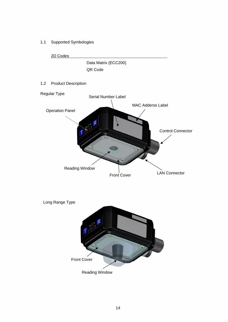
1.2 Product Description
Regular Type
Operation Panel
Serial Number Label
Reading Window
MAC Adderss Label
LAN Connector
Control Connector
Front Cover
Long Range Type
Reading Window
Front Cover

15
1.2.1 Operation Panel
The operation panel consists of an action display monitor and 2 operation keys.
• Fucntion of Monitor LED
For the monitor LED display at automatic tuning,
refer to section “4.1 Configuration parameters”.
• Teach Key
Teach Key is used in auto-tuning function.
• Read Key
Read Key is used for a test/verification. When the Read Key is pressed, the
reader acts the same as when the external synchronizing input signal is
entered. Read Key is also used for an automatic tuning in a combination with
Teach Key.
LED Color Name Description of Function
A Red Ready Turns on when Code Reader is operatable.
B Green SYNC Turns on at a synchronizing input.
C Green GO Turns on when the reader successfully reads symbols or chractrers.
D Red NG Turns on whenthe reader fails to read.
Link Green LINK Turns on when the LAN is connected.
Act Orange ACTIVE Turns on at the data transmission/reception.
Link-LED Act-LED
Read Key Teach Key
Monitor LED A to D

16
1.2.2 Code Reader Connector (17 pins)
Code Reader Connector is used for connecting the power supply and digital
input/output with your Code Reader.
• Power Input
Power input of LP-ABR supplies DC24V.
• 4 Digital Outputs: LIGHT, OUT1, OUT2 and OUT3
The 4 Digital outputs are digital signal outputs with photo-coupler isolation.
It outputs a control timing of the illumination control and the reader.
LIGHT output is a timing signal to activate the external illumination
synchronizing with the camera’s image timing.
The outputs OUT1 to OUT3 are the signals for the external output of reading
action’s status or reading result’s status. Allocation of signals to each output
and output time (setting time) can be configured by setting commands.
Each of the following signal outputs can be configured to OUT1 to OUT3.
Signal Default Setting Description
GO signal OUT1 output
GO signal is associated with Good Read, which is ON during the specified time set by the GOOUT command when the symbol is decoded successfully. And also this signal is OFF when starting the next reading.
NG signal OUT2 output
NG signal is associated with No Read, which is ON during the specified time set by the NGOUT command when the symbol is not decoded successfully. And also this signal is OFF when starting the next reading.
Ready signal OUT3 output Ready signal is ON when the reader is ready for
reading.
Busy #1 signal
Busy #1 signal is ON during a reading (except switch chattering delay), and this signal turns OFF after decoding.
In the factory default settings the signals are as below: OUT1 output GO signal, OUT2 output NG signal, OUT3 output Ready signal
When changing these parameters, save the settings to the internal flash memory (using the WSETS command) and restart the reader.
Reference

17
• Digital input (SYNC input):
This signal is a photo coupler isolated input which is used for synchronous
inputs.
[Plug the connector]
① Adjust the positions of the guide part of the cable nut and the marking of the resin part.
② After adjusting the positions of ① and main unit’s connector guide, insert the connector all the way in.
③ Screw the connector to lock.
①
②
③

18
1.2.3 LAN Connector (8 pins)
This connector is used for connecting the LAN cable (optional) of LP-ABR series
with your Code Reader.
[Plug the connector]
①
① Adjust the positions of the guide part of the cable nut and the marking of the resin part.
② Adjust the of the positions of ① and the main unit’s connector guide and insert the connector all the way in.
③ Screw the connector to lock.
②
③

19
1.2.4 Internal illumination unit
Internal illumination unit illuminates the central part of Code Reader from inside
the front cover.
Illumination unit consists of a block: CENTER which is adjacent to reading
window and four blocks: TOP, BOTTOM, LEFT, and RIGHT. Each block's
illumination brightness and light on/off are controlable.
The block CENTER is a blurry diffused illumination with no directivity. This
illumination is suitable for a reading of symbols with strong reflectivity (e.g.
symbols on mirror)
The four blocks around the CENTER are direct illuminations with directivity
and illuminate far in front of Code Reader.
You can configure the best illumination condition easily by the configuration
tool Configurator LP-ABR. Adjust the illumination area and illumination’s
intensity for a clear view.
An external illumination may be required when the view is still not clear.
Consult with our sales representative for the configuration or selection of
illumination.
1.2.5 Reading Window
Is an entrance of light for imaging.
1.2.6 Front Cover
Is an acrylic cover to protect the front surface.
1.2.7 MAC Address Seal
Indicates the MAC address of the LAN port.
Block TOP
Block BOTTOM
Block RIGHT
BLock LEFT
Block CENTER
* The position of the illumination blocks switches in the image rotating function. Refer to the section “5.7 Image Rotation” for more detail.
Reading Window

20
2 How to use
2.1 Preparation
① Establish a communication between the reader and the host device through
RS-232C interface/LAN interface. Connect a control device as needed.
<Example of Connection>
Connecting devices when the power is supplied to the cable may cause a
malfunction.
Notice
Host Device
PC, etc.
LAN Cable
Control Cable
Control Device (e.g. Power Supply)
LAN Connector
Control Connector
LP-ABR

21
② Supply power from the interface cable to the reader. The LED-A (Ready) turns
on (red) if the reader is correctly powered. A combination of 2 long beeps and 3
short beeps will indicate that the reader has started up correctly.
③ Communication port selection (RS232C, LAN)
The communication port, which can be either RS232C and/or LAN as selected
by the “COMFROM” command, is used for the following purposes:
-Receiving serial commands such as reading trigger (SYNC input)
-Reading result transmission
† RS232C interface is selected as default.
Command Description
COMFROM=0 Only RS-232C (default) COMFROM=1 Only LAN
COMFROM=2 RS-232C and LAN

22
2.2 Reading Flow (Default)
1. Good Read
- 1 short beep
- Symbol’s data will be sent through the interface (RS232C, LAN).
- Digital output “GO” is ON.
- LED-C (GO) turns on (green). Note: The activated period of “GO” and the monitor LED-C can be configured through serial commands.
2. No Read
- No beep
- Error code will be sent through the interface (RS232C, LAN). - Digital output “NG” is ON.
- LED-D (NG) turns on (red).
2.3 Configuration
LP-ABR can be configured by sending the serial command through the
communication port selected.
2.4 Transfer Image Data
Downloaded images by Code Reader can be transfered using “Configurator
LP-ABR” software from the communication port to the host computer. By the
setting of Configurator LP-ABR, the images can be picked at the standby time or
can be transtered after the finish of reading. By the setting of Configurator
LP-ABR, the images can be picked at the standby time or can be transfered after
the end of reading. Images are converted into bmp files and are transfered
through LAN interface. The transfer of a full-resolution image takes approx one
second.
Command Description
MODE=0 No image data sending (*) MODE=1
Test Mode: DO NOT USE MODE=2 MODE=3 Transfers image data every time (Continuous transfer) MODE=4 Transfers image data when the reading is “NG” (Continuous transfer) MODE=5 Transfers image data when the reading is “OK” (Continuous transfer)
*: Default setting

23
3 Operation Mode
LP-ABR has can be operated in following 2 modes. Operational Mode Command Description
Single Reading Mode SYNCMODE=0 Single read for each SYNC input. Reading Timeout Mode SYNCMODE=1 After SYNC input, the reader
continues reading during the duration time set by “TOTALLIM”. The reader sends an error code when it fails in reading when the duration time passes.
External Trigger Mode SYNCMODE=2 The reader continues reading during the SYNC input is active. It receives no g command (start reading command) .
"Read” includes capturing and decoding an image.
The Diagnostic Mode is available when the operation mode is in Single Reading
Mode.
Diagnostic Mode Command Description
Normal Mode TEST=0 For normal use and to return to Normal Mode
Test Mode TEST=1 For measurement of reading rate of symbols.
Continuous Reading Mode continue
For camera adjustment. To release the reader from Continuous Reading Mode, send a “stop” command.
Diagnostic Mode is used to configure the reader. Do not use the Diagnostic Mode
in normal operation.

24
Timing Chart
DELAY: The time from SYNC ON to reading.
CHATT: The time needed for eliminating the chattering.
IMAGE: The time duration for capturing an image.
DECODE: The time duration for decoding.
DECODELIM: The maximum time limit for decoding.
GOOUT: The length of time the GO signal is asserted.
NGOUT: The length of time the NG signal is asserted.
SERIAL: The time the data is output through the serial interface.
MAXIMG: The maximum number of images in the buffer.
WAITIMG: The interval time between capturing images.
Soft Trigger: The SYNC issued by serial command input.
Hard Trigger: The SYNC issued by digital input or Read Key.
3.1 Single Reading Mode
Code Reader performs a single read for each SYNC input.
3.1.1 Soft trigger, Good Read, Data transmission: After decode
DELAY
SYNC
IMAGE
DECODE
SERIAL
GOOUT GOOUT
DECODELIM
decode1
image1

25
3.1.2 Hard trigger, Good Read, Data transmission: After decode
3.1.3 Hard trigger, No Read, Data transmission: After decode
DELAY
SYNC
IMAGE
DECODE
SERIAL
GOOUT GOOUT
CHATT
DECODELIM
decode1
image1
DELAY SYNC
IMAGE
DECODE
SERIAL
NGOUT NGOUT
CHATT
DECODELIM decode1
image1

26
3.2 Reading Timeout Mode
Code Reader reads the symbol repeatedly during the duration time, set by “TOTALLIM” after
the SYNC input, or continues reading until the decoding is successful. If the reader cannot
decode successfully in the duration time, it stops reading and sends an error code to the host.
Typically MAXIMG is set to a number greater than one. The multiple MAXIMG enables the
Cycle Buffer Function and the simultaneous parallel processing between image import and
decoding. This may shorten the processing time.
The timing charts below are drawn referring to the enabled cycle buffer function.
3.2.1 Soft trigger, Good Read, Data transmission: After decode
3.2.2 Soft trigger, Good Read, Data transmission: After SYNC OFF
DELAY
SYNC
IMAGE
DECODE
SERIAL
GOOUT GOOUT
DECODELIM DECODELIM
WAITIMG WAITIMG WAITIMG WAITIMG
decode1 decode2
image1 image2 image3 image4 image5
TOTALLIM
DELAY
SYNC
IMAGE
DECODE
SERIAL
GOOUT GOOUT
DECODELIM DECODELIM
WAITIMG WAITIMG WAITIMG WAITIMG
decode1 decode2
image1 image2 image3 image4 image5
TOTALLIM

27
3.2.3 Hard trigger, Good Read, Data transmission: After decode
3.2.4 Hard trigger, Good Read, Data transmission: After SYNC OFF
DELAY
SYNC
IMAGE
DECODE
SERIAL
GOOUT GOOUT
CHATT
DECODELIM DECODELIM
WAITIMG WAITIMG WAITIMG WAITIMG
decode1 decode2
image1 image2 image3 image4 image5
TOTALLIM
DELAY
SYNC
IMAGE
DECODE
SERIAL
GOOUT GOOUT
CHATT
DECODELIM DECODELIM
WAITIMG WAITIMG WAITIMG WAITIMG
decode1 decode2
image1 image2 image3 image4 image5
TOTALLIM

28
3.2.5 Soft trigger, No Read, Data transmission: After decode
3.2.6 Soft trigger, No Read, Data transmission: After SYNC OFF
SYNC
DELAY IMAGE
WAITIMG WAITIMG WAITIMG WAITIMG
image1 image2 image3 image4 image5
DECODE
DECODELIM DECODELIM
decode1 decode2
SERIAL
NGOUT NGOUT
TOTALLIM
SYNC
WAITIMG WAITIMG WAITIMG WAITIMG
DELAY IMAGE
image1 image2 image3 image4 image5
DECODE
DECODELIM DECODELIM
decode1 decode2
NGOUT NGOUT
TOTALLIM
SERIAL

29
3.2.7 Hard trigger, No Read, Data transmission: After decode
3.2.8 Hard trigger, No Read, Data transmission: SYNC OFF
CHATT
DELAY IMAGE
image1 image2 image3 image4 image5
SERIAL
SYNC
WAITIMG WAITIMG WAITIMG WAITIMG
DECODE
DECODELIM
DECODELIM
decode1 decode2
NG-OUT
TOTALLIM
NGOUT
DELAY
SYNC
IMAGE
WAITIMG WAITIMG WAITIMG WAITIMG
image1 image2 image3 image4 image5
SERIAL
NG-OUT NGOUT
CHATT
TOTALLIM
DECODE
DECODELIM
DECODELIM
decode1 dcode2

30
3.3 External Trigger Mode
Code Reader reads the symbol repeatedly during the SYNC input is active. Typically
MAXIMG is set to a number greater than one. The multiple MAXIMG enables the
Cycle Buffer Function and the simultaneous parallel processing between image
import and decoding. This may shorten the processing time.
The timing charts below are drawn referring to the enabled cycle buffer function.
3.3.1 Hard trigger, Good Read, Data transmission: After decode
3.3.2 Hard trigger, Good Read, Data transmission: After SYNC OFF
DELAY
SYNC
IMAGE
DECODE
SERIAL
GO-OUT GOOUT
CHATT
DECODELIM DECODELIM
WAITIMG WAITIMG WAITIMG WAITIMG
decode1 decode2
image1 image2 image3 image4 image5
CHATT
DELAY
SYNC
IMAGE
DECODE
SERIAL
GO-OUT GOOUT
CHATT
DECODELIM DECODELIM
WAITIMG WAITIMG WAITIMG WAITIMG
decode1 decode2
image1 image2 image3 image4 image5
CHATT

31
3.3.3 Hard trigger, No Read, Data transmission: After decode or SYNC OFF
DELAY
SYNC
IMAGE
DECODE
SERIAL
NG-OUT NGOUT
CHATT
DECODELIM DECODELIM
WAITIMG WAITIMG WAITIMG WAITIMG
decode1 decode2
image1 image2 image3 image4 image5
CHATT
decode3

32
3.4 Continuous Reading Mode
In Continuos Reading Mode the reader read repeatedly. It is used for camera
tunings.
To put the reader in Continuous Reading Mode, send the serial command “continue”
to the reader, and then send the serial command “g” to start reading.
To exit the Continuous Reading Mode, send the serial command “stop” to the reader.
3.5 Test Mode
In Test Mode the reader can measure the reading ratio. It is used for checking of the
reading condition and stability.
To put the reader in Test Mode and start reading, send the serial command “TEST=1”
to the reader.
To exit the Test Mode, send the serial command “TEST=0” to the reader.
With Test Mode, the reader will output an asterisk (*) to the host for each 10% of total
number of reading. The reader will stop the Test Mode after output an asterisk 10
times.
(Example output)
*** TEST MODE ***
1 2 3 4 5 6 7 8 9 10
* * * * * * * * * *
NG 1: OK 99/SYNC 100
NG 1.00%: OK 99.00%
(Output format)
NGaaaaa: OKbbbbb/SYNCccccc[CR]
NGddd.dd%: Okeee.ee%[CR]
aaaaa : NG Count (0 - 65535, maximum number is 65535)
bbbbb : OK Count (0 - 65535, maximum number is 65535)
ccccc : SYNC Input (NOT displayed more than 65535 )
ddd.dd: NG Rate (0.00-100.00, Displayed to the second decimal place)
eee.ee: OK Rate (0.00-100.00, Displayed to the second decimal place)

33
3.6 Cycle Buffer Function
With cycle buffer function, the reader images the target serially when the positions of
moving targets are scattered against the SYNC.
In SYNCMODE=1 (Reading Timeout Mode) or SYNCMODE=2 (External Trigger
Mode), the Cycle Buffer Function is enabled when the MAXIMG number is greater
than 1one (default is four 4). Set with the MAXIMG command. If the Cycle Buffer
Function is enabled, the reader captures multiple images after receiving the SYNC
signal and then saves the images to the buffer memory (up to 4 images). The reader
starts decoding from memory location #1, if it is not successful, the reader will
attempt to read the image saved in memory location #2. The decoding is attempted
during the interval between capturing images. When the buffer memory reaches the
final location, the next image will be saved into buffer memory location #1 if the
reader has finished decoding that image. If the reader has not finished with that
image, it will wait until the decoding has finished.
Decode
1
5
9
13
1 2 3 4 Capture
1
WAIT
5
WAIT WAIT WAIT
6
WAIT
2 3 4
N-1 N N+1
WAIT WAIT WAIT
N-15 N-16 N-14
Capture
Processing Standby
[Start]
[Processing Standby Enabled(N≧17)]
Decode
Processing Standby

34
[Concept of using Cycle Buffer]
The greatest feature of this function is the imaging of the predetermined number at a constant
time interval unrelated to reading processing time. Set the number of imaging within the
MAXIMG setting (16 sheets maximum) for the imaging at regular intervals. Otherwise the
imaging interval will vary depending on the reading processing time after the number of
imaging.
Shortening the capture time by reducing the capture resolution (number of pixels) can shorten
the imaging interval.
[Configration Example]
The relation among Shutter Time (SHUTT) , Capture Time (CAPIMG), Imaging
Interval (WAITIMG) and Total Imaging Cycle (CAPCYC) are as follows. CAPCYC = SHUTT + CAPIMG + WAITIMG
Set the Moving Time T = L / V < (16 × CAPCYC)
when the moving object's speed is V and the object's moving distance is L.
Within 16 Images
Moving Speed
Moving Distance L
MAXIMG=16、SHUTT=1/1000s=1ms、CAPIMG=16ms、WAITIMG=10ms
Imaging Cycle is CAPCYC=SHUTT+CAPIMG+WAITIMG=1ms+16ms+10ms=27ms.
(1)Moving speed V when the imaging range is L=100mm is:
L/V < 16×CAPCYC
⇒ V > L/(16×CAPCYC) = 100mm/(16×27ms) = 0.231mm/s = 14(m/min.) ∴ V > 14m/min.
(2)Imaging range L when the moving speed is V=30m/min.( = 500mm/s = 0.5mm/ms)is:
L/V < 16(CAPCYC)
⇒ L < 16×CAPCYC×V = 16×27ms×0.5mm/ms = 216mm ∴ L < 216mm
Imaging Area

35
4 Configuration for Symbol Reading
4.1 Configuration parameters
This function is for automatic confituration of reading parameter. With this function,
you can configure a lot of complex parameters automatically.This function is
available by the communication from the host device as well as an easy key
operation on a lone Code Reader.
4.1.1 How to operate Auto-Tuning function
First, place a symbol for automatic setting near the center axis of the lens in
the reading distance range. Code Reader performs imaging repeatedly
during the tuning.
Fix the target to the position to place the symbol securely.
When all the preparation above is done, execute Auto-Configuration
according to the following procedure on the operation panel.
Marks for Monitor LED ■and■ Illuminate □ Extinguish
□□□□ These 4 white squares are called A, B, C and D from the left in following instructions.
↓ [Press Teach key for more than a second again to cancel the operation.]
↓
↓
① Press Teach key for more than one second to blink LED-A in standby state.
*LED blinks(■□□□□□□□)
② To start auto-tuning by Code Reader, press Read key while LED-A is blinking.
③ The result is displayed when the auto-tuning is finished.
Auto-tuning successful: -LED illumination □■■□ -3 long buzzers Auto-tuning failed: -LED illumination ■□□□ -7 short buzzers The display of results will return to the stand-by state after a certain time.

36
DO NOT turn off power during auto-tuning operation.
DO NOT send serial commands during auto-tuning operation.
Notice
④ Press Read key while the result is displayed to save the result of successful auto tuning. The result of setting changes depending on the length of time you press the button. Less than 2 seconds (Table Mode): Saves 3 types of settings and uses them switching as needed. More than 2 seconds (Manual Mode): Saves 1 setting and uses it.
(Refer to the section “4.3 Camera Control Mode”.) * You may receive less than 2 or less types of settings even if in Table Mode. * Save the setting in Manual Mode when you decode moving objects.
When the operation above is accepted, Code Reader becomes the following state for a
certain period of time and returns to the stand-by state. *LEDs illuminate ■■■■ *Buzzer sound
-in Table Mode: 3 short buzzers -in Manual Mode: 4 short buzzers

37
4.1.2 Commands Related to Auto-Tuning
In Auto-Tuning, you can configure auto-tuning operation, reference of tuning
result, selection of storing method and setting of tuning condition by
communicating with the host.
• Set the shutter speed lower limit of auto-tuning.
*SHUTTLIM=a a: 0 Shutter speed 1/60 (Default)
1 Shutter speed 1/125
2 Shutter speed 1/250
3 Shutter speed 1/500
4 Shutter speed 1/1000
5 Shutter speed 1/2000
6 Shutter speed 1/4000
7 Shutter speed 1/6000
8 Shutter speed 1/8000
9 Shutter speed 1/10000
Setting lower limit of shutter speed is required when you read a moving object.
† Setting the moving distance of the reading object less than 25% of the cell size is recommended.
e.g.) When a reading target moves at 15m/min of speed in 0.5 mm square of cell size
0.5 × 10-3 × 25% ≧ 15 / 60 × Ts
Ts ≦ 0.5 × 10⁻³ [s] = 1/2000 [s] (*SHUTTLIM=5)
• Start Auto-tuning
*setup
This command is used for starting auto-tuning. The operation after the start is the same as the one executed by the operation panel.

38
• Force-quit running auto-tuning
*cancel
Auto-tuning takes a lot of time. This command is used for canceling an
auto-tuning. Code Reader force-quits the auto-tuning.
• Check the condition of LP-ABR
*?state
This command is used for checking the condition of your Code Reader.
The answers from Code Reader are as follows.
Condition Answer Reading standby STANDBY[CR] Auto-tuning RECEIVED[CR] Waiting data save SAVEWAIT[CR] Reading (No answer)
Save Tuning Result (Table Mode)
*save
This command is used for saving a result of auto-tuning to the table mode.
When Code Reader receives this command within 40 seconds after the
completion of auto-tuning, the result of the tuning is saved to the table mode.
If no command is received, Code Reader times out and returns to reading
standby state.
Save Tuning Result (Manual Mode)
*save2
This command is used for saving a result of auto-tuning to the manual mode.
When Code Reader receives this command within 40 seconds after the
completion of auto-tuning, the result of the tuning is saved to the manual
mode. If no command is received, Code Reader times out and returns to
reading standby state.
Refer to saved result of tuning
?ddmtbl
This command is used for saving a result of auto-tuning to the manual
mode.

39
Output Example of ?ddmtbl
<SID=0>[My Reader]
******** STATUS ******** LP-ABR
last table number=-1(read only)
next table number=1(read only)
STARTDDMTBL1=1 (0: OFF 1: ON)
ENABLEDDMTBL=8 (1-8)
EDITDDMTBL=0 (1-8)
TBLTX=0 (0: OFF 1: ON)
+++++ table 0 +++++
DDMcapmode=0,0,1920,1200
DDMlight=3
DDMled=1,1,1,1,1,1
DDMbrightness=80,80,80,80,80,80
DDMshutt=2
DDMgain=3
DDMblack=0
DDMexgain=1
DDMpreproc=0,0,0,0,0
DDMmirror=0
+++++ table 1 +++++
DDMcapmode=0,0,1920,1200
DDMlight=3
DDMled=1,1,1,1,1,1
DDMbrightness=80,80,80,80,80,80
DDMshutt=2
DDMgain=3
DDMblack=0
DDMexgain=1
DDMpreproc=0,0,0,0,0
DDMmirror=0
+++++ table 2 +++++
DDMcapmode=0,0,1920,1200
DDMlight=3
DDMled=1,1,1,1,1,1
DDMbrightness=80,80,80,80,80,80
DDMshutt=2
DDMgain=3
DDMblack=0
DDMexgain=1
DDMpreproc=0,0,0,0,0
DDMmirror=0
+++++ table 3 +++++
DDMcapmode=0,0,1920,1200
DDMlight=3
DDMled=1,1,1,1,1,1
DDMbrightness=80,80,80,80,80,80
DDMshutt=2
DDMgain=3
DDMblack=0
DDMexgain=1
DDMpreproc=0,0,0,0,0
DDMmirror=0
+++++ table 4 +++++
DDMcapmode=0,0,1920,1200
DDMlight=3
DDMled=1,1,1,1,1,1
DDMbrightness=80,80,80,80,80,80
DDMshutt=2
DDMgain=3
DDMblack=0
DDMexgain=1
DDMpreproc=0,0,0,0,0
DDMmirror=0
+++++ table 5 +++++
DDMcapmode=0,0,1920,1200
DDMlight=3
DDMled=1,1,1,1,1,1
DDMbrightness=80,80,80,80,80,80
DDMshutt=2
DDMgain=3
DDMblack=0
DDMexgain=1
DDMpreproc=0,0,0,0,0
DDMmirror=0
+++++ table 6 +++++
DDMcapmode=0,0,1920,1200
DDMlight=3
DDMled=1,1,1,1,1,1
DDMbrightness=80,80,80,80,80,80
DDMshutt=2
DDMgain=3
DDMblack=0
DDMexgain=1
DDMpreproc=0,0,0,0,0
DDMmirror=0
+++++ table 7 +++++
DDMcapmode=0,0,1920,1200
DDMlight=3
DDMled=1,1,1,1,1,1
DDMbrightness=80,80,80,80,80,80
DDMshutt=2
DDMgain=3
DDMblack=0
DDMexgain=1
DDMpreproc=0,0,0,0,0
DDMmirror=0
+++++ table 8 +++++
DDMcapmode=0,0,1920,1200
DDMlight=3
DDMled=1,1,1,1,1,1
DDMbrightness=80,80,80,80,80,80
DDMshutt=2
DDMgain=3
DDMblack=0
DDMexgain=1
DDMpreproc=0,0,0,0,0
DDMmirror=0
********* END ********** LP-ABR
System version = M66C-V0.3a
Decode version = M66A-V0.3a
*Continues to the upper right ↗

40
4.2 Reading Parameter
Configure the following parameter if Auto-tuning does not work or when you want to tune
Code Reader manually. This parameter exists for each table of the table mode which is
described later. Set this parameter to the table of your Code Reader. Code Reader
operates referring to the parameter in table 0 if the setting is configured to not use the
table mode.
The following parameters are set to get decodable images:
① Reading Area [DDMcapmode]
② Illumination Control (ON/OFF) [DDMlight]
③ Advanced Setting of internal Illumination [DDMled]
④ Internal Illumination intensity [DDMbrightness]
⑤ Shutter Speed [DDMshutt]
⑥ Analog Gain [DDMgain]
⑦ Digital Gain [DDMexgain]
⑧ Black level adjustment [DDMblack]
⑨ Image Preprocessing [DDMpreproc]
⑩ Mirrored Image [DDMmirror]

41
4.2.1 Reading Area
(1) Reading Area [DDMcapmode]
This function is used for specifying a readable area from a image.
The reading area is specified depending on the X origin, y-coordinate, width and
height.
† Configuring the reading area too narrow may deviate the symbol from the reading area and may cause a read error. Make sure that the size of reading area fits the symbol.
DDMcapmode=a,b,c,d
a: Coordinate origin X (0-1275) b: Coordinate origin Y(0-955)
c: Width (4-1280) d: Height(4-960)
-Specify the full screen
DDMcapmode=0,0,1280,960
-Specify the 50 % of the center
DDMcapmode=320,240,640,480
Maximum Imaging Area
[0,0]
[1279,959]
[a,b]
d
c
Imaging Area

42
4.2.2 Illumination
(2) llumination control (ON/OFF) [DDMlight]
This command is used for configuring how the internal/external illumination
illuminate.
DDMlight=a (a: 2,3)
2: Internal illumination OFF when capturing an image
3: Internal illumination ON (with pulsed operation) when capturing an image
4: External Illumination ON when capturing an image
5: External Illumination ON always
6: External Illumination ON during synchronization
7: External Illumination ON when capturing an image
8: For Test, DO NOT USE
9: Internal illumination ON, External Illumination during synchronization
10: For Test, DO NOT USE
11: Internal illumination ON during synchronization
† “Synchronization” stands for periods of time described below. Monitor LED-B
turns on during synchronization.
1) Single Reading Mode : Synchronization ON - Decode completion
2) Reading Timeout Mode : Synchronization ON - Set synchronization
time(TOTALLIM)
3) External Trigger Mode: During External Input Signal is ON
(3) Advanced Setting of internal Illumination [DDMled]
Sets the internal illumination to be used.
DDMled=a,b,c,d,e
0: No use 1: Use
a: Internal illumination TOP b: Internal illumination LEFT
c: Internal illumination RIGHT d: Internal illumination BOTTOM
e: Internal illumination CENTER
(4) Illumination Brightness [DDMbrightness]
Sets the brightness of the internal illumination.
(Brightness of external lillumination cannot be set)
DDMbrightness=a
0 to 100 (0: Extinguish 100: Maximum Brightness)

43
4.2.3 Shutter Speed
(5) Shutter Speed [DDMshutt]
Configures the shutter speed.
If the image is still dark even with the illumination, configure the shutter speed slower
to brighten the image. Note that this may cause a blur. The following 10 speeds can
be specified.
DDMshutt=a
0: 1/60 1: 1/125
2: 1/250 3: 1/500,
4: 1/1000 5: 1/2000
6: 1/4000 7: 1/6000,
8: 1/8000 9: 1/10000
4.2.4 Extra Gain Values
(6) Analog Gain [DDMgain]
Specifies the analog gain to be configured on the camera.
Higher value will increased the camera analog gain which will produce a brighter
image.
The following values can be specified.
DDMgain=a
1 (Low) to 4(high)
(7) Digital Gain [DDMexgain]
Specifies the digital gain to be configured on the camera.
Higher value will increased the camera digital gain which will produce a brighter
image.The following values can be specified.
DDMexgain=a
1 (Low) to 15(High)

44
4.2.5 Black Level Adjustment
(8) Black Level Adjustment [DDMblack]
This is a reserved parameter. Set it to 0 always.
DDMblack=0
4.2.6 Image Preprocessing
(9) Image Preprocessing [DDMpreproc]
If the image quality is low, by using an appropriate image filter at the image
preprocessing may improve the reading accuracy
4.2.7 Mirrored Image
(10) Mirrored Symbol [DDMmirror]
Configures the reading of normal typed labels and mirrored image labels.
DDMmirror=a
0: Read only normal type (not mirrored)
1: Read only mirrored type
2: Read both of normal type and mirrored type

45
4.3 Camera Control Mode
Camera Control Parameter consists of tables whose reading parameters are stored
in and a camera control mode which operates tables.
Select one from the 2 types of camera control mode (AGC).
Fixed Gain Mode [AGC=D] (Default) In Fixed Gain Mode, the reader uses only Table #0 settings. The settings in Table #0 will not be changed automatically. Use this mode to decode a moving object. You can configure this mode even to a motionless object.
Table Mode [AGC=T]
In Table Mode, the reader configures some combinations of pre-set parameters
and uses in turn. The combination of settings are used after being stored in a
table. The detail of Table Mode is described in the next section.
Table Mode is suitable for reading of motionless symbol.
Reference
Fixed gain: D Table #0
Table #1
Table #2
Table #3
Table #4
Table #5
Table #6
Table #7
Table #8
Table: T
Camera Control Mode Table

46
4.4 Detail of Table Mode
Up to 8 tables can be used while the trigger is activated.
ENABLEDDMTBL=a (a: 1 to 8)
e.g.1) Use 3 tables (a=3)
Table #1, #2 and #3 are enabled and Table #4 through #8 will not be used. If the reader
successfully decodes a symbol with Table #1, Table #1 will be used in the next reading.
If the reader failed to decode a symbol with Table #1, the settings will switch to Table #2,
etc.
If the reader failed to decode with Table #3, the settings will switch back to Table #1.
e.g.2) Use 1 table (a=1)
Only Table #1 is enabled. Table #2 through #8 will not be used. As the result, Table #1
is always used every reading.
The following shows the structure of the Table. Each table has 9 types of parameters:
(1) DecodeArea [DDMcapmode] (2) Illumination Control [DDMlight] (3) Internal Illumination [DDMled] (4) Illumination Intensity [DDMbrightness] (5) Shutter Speed [DDMshutt] (6) Analog Gain [DDMgain] (7) Digital Gain [DDMexgain] (8) Black Level Illumination [DDMblack] (9) Image Preprocessing [DDMpreproc] (10) Mirrored Image [DDMmirror]

47
When the reading is successful, the reader uses the table setting in the next reading. When the reading is failure, the reader attempts to read using the next table setting.
The flow chart of Table mode is shown below.
< Flow char of Table Mode >
4.4.1 Edit Table
Edit tables using serial commands. (1) Set the target Table #.
Send the serial command below to assign the table number to be edited. EDITDDMTBL=a (a: 1 to 8)
(2) Configure the parameters. Refer to section “4.1 Configuration parameters” for detailed information.
(3) Edit another table Repeat the step 1 & 2.
(4) Check the target Table You can check the target table status using the following command. ?ddmtbl
Read OK? Yes
Yes
No
Trigger
Use this Table
Increment table number Read OK?
No
Use the first table in the next reading
Use the next table

48
5 Advance Features
5.1 Preset Mode
In Preset mode, LP-ABR series read only the symbols whose data match the preset
data.
This function has 2 modes whose registration method and data collation method of
preset data are different.
PREM=0[CR](*): Preset Mode 0 (Preset Mode is disabled)
PREM=1[CR]: Preset Mode 1 (Preset data is the first decoded one after power up)
PREM=2[CR]: Preset Mode 2 (Preset data is registered in advance)
*: Default
To disable Preset Mode, send the command “PREM=0”.
5.1.1 Preset Mode 1
In this mode, the preset data is the first decoded data after power up.
Data comparison is only successful when the code matches completely.
The preset data must be set as every time the reader is powered on because the
data is not saved to internal flash memory.
Setup procedure of Preset Mode 1
1. Send the following commands
PREM=1[CR]
WSETS[CR] : Save the settings to internal flash memory.
2. Power-on reset
3. Read the symbol that contains the data to be used as the preset data.

49
5.1.2 Preset Mode 2
In this mode, the preset data is configured by the serial command. Data
comparison is completed by both complete and partial matching. It is possible to
save the preset data to internal flash memory.
Send the following command to set this mode:
PREM=2[CR]
SET=PREDabcd[CR] : Set the preset data (data is “abcd”)
SET=PRENa[CR] : Set the number of digits (a: 0 to 100)
WSETS[CR] : Save the settings to internal flash memory
e.g.1) Example 1: Only ”12345” is valid
12345 : match
1234 : mismatch
123456 : mismatch
012345 : mismatch
PREM=2[CR]
SET=PRED12345[CR] : Set the preset data (data is “12345”)
SET=PREN5[CR] : Set the number of digits (5 digits)
WSETS[CR] : Save the settings to internal flash memory
e.g.2) Example 2: Valid when first 4 digits are “ABCD”.
ABCD : match
ABCD333 : match
ABCD777777 : match
ABC : mismatch
DABC333 : mismatch
77ABCD77777 : mismatch
PREM=2[CR]
SET=PREDABCD[CR] : Set the preset data (data is “ABCD”)
SET=PREN0[CR] : Set the number of digits (no count)
WSETS[CR] : Save the settings to internal flash memory

50
e.g.3) Example 3: Valid when the length is 10 digits and the data from 3rd-digits
to 6th-digits are “ALFA”.
00ALFA1234 : match
AAALFAAAAA : match
00ALFA12345 : mismatch
0ALFA12345 : mismatch
PREM=2[CR]
SET=PRED??ALFA????[CR]: Set the preset data (data is “??ALFA????” and
“?” is mask.)
SET=PREN10[CR]: Set the number of digits (10 digits)
WSETS[CR]: Save the settings to internal flash memory

51
5.1.3 Output the status of Preset Mode
?pre[CR] : Output the preset status
(Example output)
PREM=0 (0: non 1: power on 2: saved)
PRESET LENGTH: 13
DATA(HEX):
34 39 3F 3F 3F 3F 3F 3F 3F 3F
3F 3F 3F
DATA(ASCII):
49???????????
(Output format)
PREM=a (0: non 1: power on 2: saved)[CR]
PRESET LENGTH: b[CR]
DATA(HEX): [CR]
XX XX XX XX XX XX XX XX XX XX[CR]
XX XX XX XX XX XX XX XX XX XX[CR]
XX XX XX XX [CR]
DATA(ASCII): [CR]
xxxxxxxxxxxxxxxxxxxxxxxx
a : Preset Mode
b : The digit of the length of the preset data
XX XX … : Preset data character (in hex)
xxxxxx… : Preset data character (in ASCII/JIS)
If the preset data include control code, it is transferred to “*”.

52
5.2 Output Additional Information
5.2.1 Output the scanned data adding Code Reader’s individual name
It can be used for multi-configuration with the reader. Host computer can recognize
the data which reader has sent.
Set an individual name to each reader
MYNAME=aaaa aaaa: (Alphanumeric strings from 1 to 31 digits)
The name of all Code Readers is “My Reader” in default setting. Make sure to set an
individual name to each Code Reader before using this function.
Configure to output individual name.
The output method is selectable by the connection with the host device.
NAMETX=a,b a=0: No Code Reader name will be included on the reading
result (RS-232C)
1: Code Reader name will be included on the reading result
(RS-232C)
b= 0: No Code Reader name will be included on the reading result
(LAN)
1: Code Reader name will be included on the reading result
(LAN)
Skip b: Configure LAN same with RS-232C
5.2.2 Warning Information to avoid No Read
Add a Warning Information to the symbol data for monitoring the reading condition.
Output format: (CcccEeeeDddd)
ccc: Contrast Information for the captured image
eee: Unused Error Correction rate
ddd: Decodability margin
e.g.1) Good Read
Data Output: (C082E100D091)A123456A
Calculate contrast value of a symbol including quiet zone. The decoder
determines a rectangular area for the symbol and calculates the contrast value
from its brightness level. If there are multiple symbols, the calculated value is for
the first decoded symbol.
e.g.2) No Read
Data Output: (C000E000D000) BR

53
“000” is added in case of No Read.
5.2.3 Symbol Type Information
Add symbol type information (decoded symbol type) to the head of decoded symbol
and output is in serial. Symbol Type is not added at No Read.
5.2.4 Decoding Time
Add decoding time to the symbol data.
5.2.5 Total Reading Time Information
Add number of images captured after trigger input and Total time from trigger
input to serial data output. Total Reading Time is not added at No Read.
Output format: (aa, bbbbbms)
aa: Number of images, bbbbb: Total time [ms]
5.2.6 Contrast Information
Add the Contrast Information of the last decoded image.
Good Read
Calculate contrast value of a symbol including quiet zone. The decoder
determines a rectangular area for the symbol and calculates the contrast value
from its brightness level.
If there are multiple symbols, the calculated value is for the first decoded
symbol.
No Read
Calculate contrast value for the whole image.
Output format: (aaa, bbb, ccc) 13 bytes
aaa : Maximum value of reflectance (000 to 255)
bbb : Minimum value of reflectance (000 to 255)
ccc : Contrast [%] =100 x (aaa - bbb) / 255 (000 to 100)
Symbol Type Code Type Information Data Matrix ]d1 QR Code ]Q1

54
5.2.7 Quality Information
The percentage of the Unused Error Correction codeword of the 2D code is
added to the decoded data.
For example, if the decoder does not use any error correction, this value would
be 100. The reader outputs the quality information individually if there are
multiple symbols. Quality Information is not added at Reading Error.
Output format: (QT: ddd) 8 bytes
ddd: Quality (000 to 100)
5.2.8 Symbol Coordinates
The positional data of the symbol in the image is output along with the decoded
data.There are two types of output information; barycentric coordinates and
rectangular coordinates.
(1) Barycentric coordinates
The origin (+0000, +0000) is the left-top edge of a field of view.
(Example output)
10000000099070(+0122,+0024)
Output format: Header + Data + (abbbb,acccc) + Terminator
a : + or -
bbbb: X coordinate of a symbol’s barycenter (9999 to +9999)
cccc: Y coordinate of a symbol’s barycenter (-9999 to +9999)
(2) Rectangular coordinates
The origin (+0000, +0000) is the left-top edge of a field of view.
(Example output)
10000000099070(+0269,+0011)(+0455,+0086)(+0386,+0270)(+0198,+019
9)

55
(Output format)
Header + Data + (A1) + (A2) + (A3) + (A4) + Terminator A1 – A4 : (abbbb,acccc) a : + or -
bbbb: X coordinates of four corners of a symbol (-9999 to +9999)
cccc: Y coordinates of four corners of a symbol (-9999 to +9999)
(3) Barycentric / Rectangular coordinates
Outputs coordinates of both barycenter and four corners of a symbol.
(Example output)
10000000099070(+0007,+0103)(+0269,+0011)(+0455,+0086)(+0386,+0270)(+
0198,+0199)
(Output format)
Header + Data +(B) + (A1) + (A2) + (A3) + (A4) + Terminator
(B): Barycentric coordinate
(A1)(A2)(A3)(A4): Rectangular coordinates
B, A1-A4: (abbbb,acccc)
a : + or -
bbbb: X coordinate of barycenter and X coordinate of four corners of a symbol
(-9999 to +9999)
cccc: Y coordinate of barycenter and Y coordinate of four corners of a symbol
(-9999 to +9999)
Field of View
Origin
Barycentric coordinates
A1
A2
A3
A4

56
5.2.9 Table Number
Adds table number given at reading to sybmol data.
(Example output)
10000000099070(ddmtbl=3)
(Output format)
Header + Data + (ddmtbl=a) + Terminator
a : Table number

57
5.3 Save Image
Maximum 16 captured images can be stored by increasing the number of cycle
buffers memory. Set number of cycles buffer memory is the number of storable
images.
MAXIMG=a[CR] a=1-16 Specify number of cycle buffer memory.
MAXIMG=1[CR] (*)
*: Default
5.3.1 Save Preprocessed Image
Select an image to save from the 2 images captured before or after
preprocessing. (Only for latest image)
IMGSEL=0[CR] Save captured image (Raw image)
IMGSEL=1[CR] (*) Save decoded image(*)
*: Default
5.3.2 Overwrite save
When saved images exceed cycle buffer memory, the oldest image will be
overwritten.
5.3.3 Preparation for transmitting the saved image
Using “Configurator LP-ABR” software allows the download of the saved image
that has been completed the preparation of transmission to the host.
† When the Camera Control Mode is other than Table Mode
IMGFRAME=0,a[CR] a=1 to 16
1: Preparation for last saved image.
2 to 16: Preparation for (a-1) previous image from the latest
† When the Camera Control Mode is Table Mode
IMGFRAME=1,b[CR] b=1 to 8
Prepare an image taken in table No. (b) for transmitting.

58
5.3.4 Output the settings of save image
?IMG[CR] Output the status
(Example output)
<SID=0>[My Reader]
******** STATUS ******** LP-ABR
IMODE=0 PX=0 PY=0 WX=1920 WY=1200
CAPMODE=0,0,1920,1200
DECMODE=0,0,0,1920,1200
IMGSEL=1 (0: captured image 1: decoded image)
CAPDLY=0
MAXIMG=1 (1-16) WAITIMG=100 (0-1000)
CAPLIM=0 (0: OFF 1: ON)
********* END ********** LP-ABR
System version = M66C-V0.1q
Decode version = M66A-V0.1q
(Output format)
<SID=0>[My Reader]
******** STATUS ******** LP-ABR
IMODE=a PX=b PY=c WX=d WY=e
CAPMODE=f,g,h,i
DECMODE=j,k,l,m,n
IMGSEL=o (0: captured image 1: decoded image)
CAPDLY=p
MAXIMG=q (1-16) WAITIMG=100 (0-1000)
CAPLIM=r (0: OFF 1: ON)
********* END ********** LP-ABR
System version = M66C-V0.1q
Decode version = M66A-V0.1q

59
a : Trimming b,c,d,e : Trimming position (Left, Top, Width, Height) f,g,h,i : Capture area (Left, Top, Width, and Height) j : Not link/link with capture area k,l,m,n : Decode area (Left, Top, Width, and Height) o : Image type (Captured image, Decoded image) p : Delay time after SYNC-ON to capture start (ms) q : Number of cycle buffer memory r : Overwrite/not overwrite the cycle buffer memory when the
number ofcaptured imaga exceeds the number of cycle buffer memory
s : Image rotation (0 degree / 180 degree)

60
5.4 PLC Link
With PLC link, you can write a reading result of symbols directly to the PLC internal
data memory (programable logic controller) through RS-232C or LAN interface.
5.5 Simultaneous reading of multiple labels
In symbol reading mode, multiple (up to 10) labels can be read simultaneously.
The order of reading data output can be configured under following conditions.
1. In order of processing completion
2. In order of preset number of digits
3. In order of preset matching characters
4. In order of preset symboligies
† Setting more symbols in an image than the number of preset symbols causes
output failure.

61
5.6 Symbol Printing Check
This function judges a printing quality of a two-dimensional symbol captured by Code
Reader using in-line. It verifies the print quality and output the result by using
evaluation parameters of ISO15415 or AIM DPM-1-2006.
Printing quality of symbols flowing on manufacturing line is maintained at a certain
level by being checked in-line. By checking the printing quality soon after marking,
detailed time-dependent change of a marking system can be seen based on the
evaluation parameter.
Notice that this function is for a simple check that outputs the evaluation result in
the same format with standard evaluation parameter. It cannot be used as a
proper two-dimensional symbol verifier.
Verification results of this function may be affected by the change of imaging
conditions of Code Reader. To prevent a variance of evaluation result, use this
function under the same imaging condition (especially following conditions) as
much as possible.
- Reading distance
- Illumination condition (Light ON/OFF configuration of internal/external illumination, illumination brightness)
- Shutter speed
- Analog gain
- Digital gain
- Black level adjustment
- Inclination of the symbol surface against Code Reader (tilt, skew, pitch)
- Amount of light around Code Reader
Processing time becomes longer than regular symbol reading when this function is
active. Turn off when this function is not necessary.
Reference

62
5.6.1 Supported Symbologies
i. 2D Codes
Data Matrix (ECC200)
QR Code
5.6.2 Symbol Printing check Items to be output
The evaluation values are output on a scale of 5 levels (0 to 4) by each evaluation
items."Overall Quality" means a value of each element's lowest grade. (If there are 5
evaluation items and the determination value was 4,3,2,3,4, the overall quality is 2.
Evalutation items to be used for overall determination is selectable.
① 2D Codes(Select an evaluation item from ISO and AIM.) No. Evaluation Items 0 Overall Quality(Lowest value of selected evaluation item) 1 Contrast (ISO) / Cell Contrast (AIM) 2 Modulation (ISO) / Cell Modulation (AIM) 3 Fixed Pattern Defection 4 Decode 5 Non-uniformity of Axis 6 Non-uniformity of Grid 7 Unused Error Correction
5.6.3 Digital Output of Determination in Symbol Printing Check
When Print Check Output is enabled, the determination can be output digitally in
check result. Configure a threshold to determine whether the overall judgment is OK
(GOOUT) or NG (NGOUT).
If a threshold is configured 2:
Outputs OK when an overall quality is 2,3, and 4
Outputs NG when an overall quality is 0 and 1
If a thredhold is configured 0, the determination is output in a determination of
regular symbol reading without a determination in check result.

63
5.7 Image Rotation
Rotates an image 180 degrees before a capture. The rotated image is used in all the
process (decoding, saving data, etc) after the rotation.
After the rotation, the layout of illumination blocks will be replaced as shown below.
[0,0]
[1279,959]
[0,0]
[1279,959]
Image rotation enabled No image rotation (Default)
Block Top
Block Bottom
Bloc
k Le
ft
Bloc
k R
ight
Block Bottom
Block Top
Bloc
k Le
ft
Bloc
k R
ight

64
6 LAN (TCP/IP) connection
6.1 Preparation
Configure the network setting to use the LAN interface.
6.2 Configure IP address
6.2.1 Configure through RS232C interface
Connect the reader to a PC through a RS232C cable.
Start a terminal software “Configurator LP-ABR” on a host computer.
Operate entering various commands from the terminal software.
IPADR: Configures an IP address and number of sub net mask bits in
command.
* The number of mask bit can be omitted if you do not want to change the sub
net mask.
Enter "IPPORT =" command to configure a service port (for reading result
transmission) in TCP server connection.
Enter "IPPORT2 =" command to configure a service port (for image data
transmission) in TCP server connection. (Another port also can be specified.)
Configure the default gateway address by the command below.
*Set the same network as IP address.
Confirm the LAN settings by the command below.
Save the settings to internal flash memory by the command below.
* “Write OK” is sent when the settings are saved Write OK.
WSETS
?LAN
GWADR =192.168.209.254
IPPORT=27110
IPPORT2=27110
IPADR=192.168.209.10/24

65
Turn off power and restart the reader
6.2.2 Configure through LAN interface
Configure settings through LAN interface, if the IP address and the port number
of the reader are known. Make sure the IP address of the superior computer is
set into the same network as the reader.
- Configuration procedure is same as RS232C.
Connect the LP-ABR and the PC for setting with a LAN cable.
Start the terminal software "Configurator LP-ABR" in the host PC.
Specify the IP address / port number of this product as the connection point of
the terminal software.
The subsequent operation is the same as the setting from the RS-232C
connection.
† If the IP address of this product is in a different network, reconfigure the IP
address of the PC.
6.3 Default Settings
IP address : 192.168.209.10
Sub net mask : /24(same as 255.255.255.0)
Port number (only for reading result transmission) : 27110
Port number(only for image data transmission) : 27110
Default gateway address : 192.168.209.254

66
e.g.) Settings example
Setup value is displayed enclosed in “ [>> “ and ” ] ”.
The dump screen of the computer and Code Reader is displayed as described in the
box above. The contents of the communication is set as follows:
[Current operating status]
IP address : 192.168.209.10
Sub net mask : /24
Default gateway : 192.168.209.254
Port number (only for reading result transmission) : 27110
[Setting (Effective at next activation) ]
IP address : 192.168.0.101
Sub net mask : /24
Default gateway : 192.168.0.1
Port number (only for reading result transmission) : 60000
† To enable the setting, save to flash memory in WSETS command and
power off to reset.
IPADR=192.168.0.101/24 IPPORT=60000 GWADR=192.168.0.1 ?LAN <SID=10>[My Reader] ******** STATUS ******** LP-ABR IP address (IPADR) : 192.168.209.010 [>> 192.168.0.101] Sub net mask (/n) : 255.255.255.000 [>> 255.255.255.000] Default gateway (GWADR) : 192.168.209.254 [>> 192.168.0.1] Barcode port (IPPORT) : 27110 [>> 60000] Image port (IPPORT2) : 27110 [>> 27110] Send Barcode IP (IPBAR) : 000.000.000.000:27120 Send Image IP (IPIMG) : 000.000.000.000:27130 connection-retry(RTIME) : 0 session-timeout (STOUT) : 0 MAC address : 00:16:fc:07:ff:f5 ********* END ********** LP-ABR System version = M66C-V0.1q Decode version = M66A-V0.1q

67
6.4 Check for LAN settings
6.4.1 Through RS-232C interface
LAN setting can be confirmed through RS-232C interface anytime.
?Confirm the LAN settings by the command below.
The following parameters are sent to the host:
- IP address - Sub net mask - Default gateway - Port number of TCP server connection (only for reading result transmission) - Port number of TCP server connection (only for image data transmission) - Destination of TCP client communication (only for reading result transmission) - Destination of TCP client communication (only for image data transmission) - Connection request interval (only for TCP client communication) - Detection timer (only for TCP client communication)
6.4.2 Through LAN interface
Communication state can be checked by UDP (User Datagram Protocol), if the
network address is already known.
Set IP address of the host into the same network as the reader.
Connect LP-ABR series to the PC for configuration with a LAN cable.
Specify the broadcast / port number as a UDP communication destination. † The port number is 49460 fixed.
† If multiple LP-ABR are connected in a same network, respective devices will
respond.
Confirm the settings by the command below.
The following parameters are output in a line:
- Local IP address (IP address of TFIR-31LAN) - Local port number (Port number of TCP/IP server of LP-ABR series) - Sub net mask - Default gateway - MAC address (last 3 bytes)
?who
?LAN

68
6.5 Connect to LAN
Use a dedicated LP-ABR series LAN cable to connect. Auto-negotiation function
which can automatically configure both communication speed (1Gbps, 100Mbps,
10Mbps) and communication mode (Full Duplex, Half Duplex) is mounted on the
cable. Therefore, configure the LAN setting (communication speed and
communucation mode) of your computer to auto-setting at a one-to-one
communication through a crossover cable.
6.6 Manage Commnunication Status
The LP-ABR series supports 4 types of communication method:
- TCP server communication (for all commands)
- TCP client communication (for reading result transmission)
- TCP client communication (for image data transmission)
- UDP communicatoin (for administration)
[TCP/IP connection]
The reader works as a TCP/IP server whose port number can be set to any value.
Only one client can be connected at a time.
The reader will disconnect in the following situations:
- Receive close request from the client
- Detect transmission error
In the following cases, the reader cannot detect disconnect state:
- A UTP cable was removed before the client sent close request.
- The client aborted the system without sending close request.
To recover the connection, send the command “discon” through RS232C
interface for forced termination, and then retry the connection.
e.g.)
(Command) discon 27110

69
[TCP client connection for transmission of reading result]
The reader also works as a TCP/IP client whose access point (IP address: port
number) can be set. Configure the connection timing by the command RTIME
(Connection request interval).
- Connect every time when you send data
- Connect automatically every time the reader is powered on
Once a connection is established, the reader will disconnect in the following
cases.
- The duration time passes (always-on connection is also possible)
- The reader receives a disconnect request from the server/client
- The LP-ABR detects a send error
You can disconnect at any time with discon (forced disconnection) command.
e.g.)
(Command) discon IPBAR
[TCP client connection for transmission of image data]
The reader also works as a TCP/IP client whose access point (IP address: port
number) can be set. Configure the connection timing by the command RTIME
(Connection request interval).
- Connect every time when you send data
- Connect automatically every time the reader is powered on
Once a connection is established, the reader will disconnect in the following
cases.
- The duration time passes (always-on connection is also available)
- The reader receives a disconnect request from the server/client
- The LP-ABR detects a send error
You can disconnect at any time with discon (forced disconnection) command.
e.g.)
(Command) discon IPIMG

70
[UDP Communication]
Code Reader also works as an UDP server with a fixed port number (49460).
The connectionless UDP communication can communicate with multiple
superior PCs.
When you send data in a broadcast from the superior PC, all devices on the
LAN will respond. With broadcast, you can:
- Get a list of LP-ABR that is running normally on the LAN.
- Get port number/terminal information of unknown IP address/TCP server
communication
You can shut down TCP server communication using UDP communication.
6.7 Serial command for LAN settings
?LAN
Get a list of settings for LAN connection.
IPADR=<IP address in dotted notation>/<Bit number of subnet mask>
Set IP address and subnet mask of the reader. † If you do not change the subnet mask, the mask bit numer can be omitted.
GWADR=<IP address in dotted notation>
Set default gateway address of the reader. † Set the same network with the IP address.
IPPORT=<TCP/IP port number>
Set TCP/IP port number of the reader.
IPBAR=xxx.xxx.xxx.xxx: nnnn
Destination IP address of reading results: set the port number.
Sends reading results from the TCP server when the destination IP address is
0.0.0.0.
Sends reading results from the TCP client when the destination IP address is
other than 0.0.0.0.
xxx.xxx.xxx.xxx Destination IP address
nnnn Destination port nimber (1 to 63335)

71
IPIMG=xxx.xxx.xxx.xxx: nnnn Destination IP address of image data: Configure the port number. Sends reading results from the TCP server when the destination IP address is 0.0.0.0. Sends reading results from the TCP client when the destination IP address is other than 0.0.0.0.
xxx.xxx.xxx.xxx Destination IP address nnnn Destination port nimber (1 to 63335)
RTIME=<Connection request interval> Set the interval time that the TCP client communication attempts to reconnect to 0 to 100 seconds. When the interval time is 0, Code Reader connects every time when you send data. When the interval time is other than 0, Code Reader connects automatically (at the same time the reader is powered on). This configuration change is enabled at the next connection.
STOUT=<Duration time> Set the interval time that Code Reader requests a disconnection in 0 to 100 seconds after the lost of data to transmit and receive from the TCP client. When the interval time is other than 0, Code Reader does not send the disconncetion request.(Always-on connection).
TCPCS=a (a=0; Disable a=1; Enable) Set the function of data arrival confirmation. If enabled, the reader will wait to send the next data until receiving “Ack”, which is associated with the previous data, from the host.
?who Get the following status: .
Local IP address (IP address of the reader) Local port number (TCP server port number of the reader) Subnet mask Deffault gateway MAC address (last 3 bytes)

72
?netstat
Outputs following information in a line.
Local IP address (IP address of the reader)
Local Port number (TCP server port number of the reader)
Remote IP address(IP address of the connected PC)
Remote Port number (Port number of the connected PC)
TCP/IP server socket status
?netstat IPBAR
Outputs information about the destination of reading result in a line.
Local IP address (IP address of the imager)
Local Port number (TCP client port number of the imager)
Remote IP address (IP address to send reading results)
Remote Port number(Port number to send reading results)
Status of TCP client communication to send reading results
?netstat IPIMG
Outputs information about the destination of reading result in a line.
Local IP address (IP address of the imager)
Local Port number (TCP client port number of the imager)
Remote IP address (IP address to send image data)
Remote Port number (Port number to send image data)
Status of TCP client communication to send image data
?version (*)
Outputs following information in a line.
Local IP address (IP address of the reader)
Local Port number (TCP server port number of the reader)
System version
Decoder version
Model name
discon<TCP/IP Port number>
Shut down TCP/IP connection of the specified port number.
* <TCP/IP port number> should be set in decimal.
e.g.) discon 27110

73
6.8 Iinitialize LAN address
If the configured address is unknown, send commands to start the reader with
default setting through RS-232C im following steps:
- Send a command SET=LAN.
- Send a command WSETS.
- Restart the reader.
Default settings
IP address : 192.168.209.10
Sub net mask : /24
Port number of TCP server : 27110 (only for sending captured data)
: 27110 (only for image data transmission)
Default Gateway : 192.168.209.254

74
7 Serial Command (RS-232C, LAN)
- The following serial commands can be used through both RS232C and LAN
(TCP/IP) interface unless otherwise specified.
Serial command format
Serial command + [CR] Default (Backward compatible)
[Header] + Serial command + [Terminator]
- To add header and terminator characters to a serial command, send the command
"CMDFORM=1".
The header and terminator characters are same with the ones to add to
captured data. This is a compatible operation without the terminator. .
- To return the input format of the configuration commands to compatible
(configuration command + [CR] ), send the command “CMDFORM=0”.

75
7.1 Communication Term Command Description (*)=Default
Baud rate BAUD=aaaa Baud rate of RS-232C aaaa=1200; 1200bps, aaaa=2400; 2400bps, aaaa=4800; 4800bps, aaaa=9600; 9600bps, (*), aaaa=19200; 19200bps, aaaa=38400; 38400bps, aaaa=57600; 57600bps, aaaa=115200; 115200bps, Frame FRAME=0 7 bits, Odd, Stop bit 1 FRAME=1 7 bits, Odd, Stop bit 2 FRAME=2 7 bits, Even, Stop bit 1 FRAME=3 7 bits, Even, Stop bit 2 FRAME=4 8 bits, None, Stop bit 1 (*) FRAME=5 8 bits, None, Stop bit 2 FRAME=6 8 bits, Odd, Stop bit 1 FRAME=7 8 bits, Odd, Stop bit 2 FRAME=8 8 bits, Even, Stop bit 1 FRAME=9 8 bits, Even, Stop bit 2 Header HEAD=a Header character a=0; None (*) a=1; [SX] a=2; [EC] Terminator TERM=a Terminator character a=0; None a=1; [EX] a=2; [EX][CR] a=3; [CR][LF] (*) a=4; [CR] a=5; [CR][TAB] a=6; [TAB][CR] Command CMDFORM=0 Command+[CR] or Command+[CR][LF] (*) Format CMDFORM=1 [Header]+Command+[Terminator] Separator SEPA=a Character code a=0; None a=1; & a=2; , (Comma) (*) a=3; [FS] (1C hex) a=4; [GS] (1D hex) a=5; [SP] (20 hex) Prefix PREFIX=a Prefix character =a,\bb a=0; Disable (*) a=1; Enable bb; Suffix character(Hexadecimal code (*1) bb=00(*) [NUL] When omitting “bb”, configured identifier will not changed. Suffix SUFFIX=a Suffix character =a,\bb a=0; Disable (*) a=1; Enable bb; Suffix character(Hexadecimal code (*1) bb=00(*) [NUL] When omitting “bb”, configured identifier will not changed. RS/CS control RSCS=0 Disable RTS/CTS flow control (*) RSCS=1 Enable RTS/CTS flow control TCP/IP arrival confirmation
TCPCS=0 Disable data arrival confirmation (*) TCPCS=1 Enable data arrival confirmation
COM Port (Sync command, Data output)
COMFROM=0 RS-232C only (*) COMFROM=1 LAN only COMFROM=2 RS-232C and LAN
Control Code LABELTX=0 Pass through (*) LABELTX=1 Change Control code to ASCII code within [hex].
Timeout period TXWAIT=a Timeout period for decoded data a=1000 to 2500 [ms]; 10[ms] step 1000[ms] (*)
(*1) Refer to “7.15 Table of Character Code”

76
7.2 Symbologies Term Command Description (*)=Default
Common SET=#M0 Disable all symbologies
SET=#M1 Enable all symbologies SYMHEAD=#a Header character for all symbologies =#a,\bb a=0; Disable (*) a=1; Enable bb; Identifying character (Hexadecimal code (*1)) When omitting “bb”, configured identifier will not changed. SYMFOOT=#a Footer character for all symbologies =#a,\bb a=0; Disable (*), a=1; Enable、 bb; Identifying character (Hexadecimal code (*1)) When omitting “bb”, configured identifier will not changed.
GS1GS=a Convert characters which indicate the data delimiter of GS1 related symbols(FNC1)
=a,\bb a=0; Not convert, a=1; convert(*)、
bb; Delimiter after conversion (Hexadecimal code (*1)) bb=1D (*) [GS]
When omitting “bb”, configured identifier will not changed. Multi-Labels LABELS=a Number of labels a=1 to 10; a=1(*) OUTFORM=0 Output in the order of decoding (*) OUTFORM=1 Output in the order of the specified digit-number OUTFORM=2 Output in the order of the specified characters OUTFORM=3 Output in the order of the specified symbologies
SET=$Na-b Set label number and verification digit number a=1 to 10; Label number b=0 to 9999; Digit number
SET=$Ca-bbcc
Set label number and verification character a=1 to 10; Label number bb; The first character in Hexadecimal cc; The second character inHexadecimal (Hexadecimal code (*1))
SET=$Sa-b Set label number and verification symbologies a=1 to 0; Label number b; Symbol identifier
(*1) Refer to “7.15 Table of Character Code”

77
Term Command Description (*)=Default
DataMatrix SET=dM0 Disable DataMatrix SET=dM1 Enable only for square shaped and normal DataMatrix
SET=dM2 Enable only for square shaped and inverse DataMatrix SET=dM3 Enable only for square shaped and normal/inverse DataMatrix SET=dM5 Enable only for square/rectangle shaped and normal DataMatrix
SET=dM6 Enable only for square/rectangle shaped and inverse DataMatrix SET=dM7 Enable all types of DataMatrix (*)
DIGIT=db,c Set minimum (b) and maximum (c) digit numbers of DataMatrix
EDIT=db,c Output DataMatrix data within a range of b-digits to c-digits
SYMHEAD=da Set header character of DataMatrix
=da,\bb a=0; Disable (*) a=1; Enable
bb; Delimiter (Hexadecimal code (*1)) bb=64 (*) character“d”
When omitting “bb”, configured identifier will not changed. SYMFOOT=da Set footer character of DataMatrix =da,\bb a=0; Disable (*) a=1; Enable
bb; Delimiter (Hexadecimal code (*1)) bb=64 (*) character“d”
When omitting “bb”, configured identifier will not changed. QR-Code SET=QM0 Disable QR-Code (*) SET=QM1 Enable only for normal QR-Code SET=QM2 Enable only for inverse QR-Code
SET=QM3 Enable QR-Code (normal/inverse) (*)
DIGIT=Qb,c Set minimum (b) and maximum (c) digit numbers of QR-Code
EDIT=Qb,c Output QR-Code data within a range of b-digits to c-digits
SYMHEAD=Qa Set header character of QR-Code =Qa,\bb a=0; Disable (*) a=1; Enable
bb; Delimiter (Hexadecimal code (*1)) bb=51(*) character“Q”
When omitting “bb”, configured identifier will not changed. SYMFOOT=Qa Set footer character of QR-Code =Qa,\bb a=0; Disable (*) a=1; Enable
bb; Delimiter (Hexadecimal code (*1)) bb=51(*) character“Q”
When omitting “bb”, configured identifier will not changed.
(*1) Refer to “7.15 Table of Character Code”

78
7.3 Symbol Reading (Operating mode, adjustment and diagnostic) Term Command Description (*)=Default
Reading g BR=a DECODELIM=a
Start reading (SYNC ON) † The default setting is valid only RS-232C interface No read message a=0 None, a=1 "BR"(*), a=2 "ERROR", a=3 "?" Set the time limit for decoding process a=100 to 10000 [ms], 10[ms] step a=500 [ms](*)
Operation Mode
SYNCMODE=a VOUT=a TOTALLIM=a
a=0; Normal Mode a=1; Reading Timeout Mode (*) a=2; External Trigger Mode Output timing a=0,1 (0: After decoding (*), 1: After SYNC off) Decode timeout、a=XXXX [ms],10[ms]step, Default: 3000[ms] (*)
Continuous Reading Mode
continue stop contintvl=a ?contintvl
Enable Continuous Reading Mode Stop Continuous Reading Mode (back to Normal Mode) (*) Set a time interval of reading a= 0 to 9 [Unit: s] a=1 [s] (*) a=10 to 999 [Unit: ms] Check the value of contintvl
Test Mode TEST=a TMN=a
a=0; Normal Mode (*), a=1; Test Mode Number of reading times in Test Mode a=10 (*) -1000 (10 steps)
I/O Test IOTEST=a,b Turn on I/O output during specified time a=D1 ;DOUT1 port D2 ;DOUT2 port D3 ;DOUT3 port b=0 OFF(*) (Output OFF in any port) 1 to 1000 Turn on during specified time [ms]、 -1 Remain ON
Reading Statistics
?total Check number of times for SYNC, Good Read, No Read from Power-on reset
clrtotal Clear the value of number of times
Display Reading Time
?dect Check decoding time of Good Read, No Read (Minimum, maximum and average)
clrdect Clear the value of decoding time
Warning Information
CHKBCR=a (,b)
a=0; Disable addition for RS232C (*) a=1; Enable addition for RS232C b=0; Disable addition for LAN (*) b=1; Enable addition for LAN
Omit (,b): Set RS-232C and LAN in the same way (=a)
Symbology Information
SYMBOLTX=a a=0; Disable addition of SYMBOLTX (*) a=1; Enable addition of SYMBOLTX
Decoding time DTTX=a (,b) a=0; Disable addition of DTTX for RS-232C(*) a=1; Enable addition of DTTX for RS-232C b=0; Disable addition of DTTX for LAN(*) b=1; Enable addition of DTTX for LAN Omit (,b): Set RS-232C and LAN in the same way (=a)

79
Term Command Description (*)=Default
Total time of decoding
TTTX=a (,b) a=0; Disable addition of TTTX for RS-232C(*) a=1; Enable addition of TTTX for RS-232C b=0; Disable addition of TTTX for LAN(*) b=1; Enable Disable addition of TTTX for LAN Omit (,b): Set RS-232C and LAN in the same way (=a)
Swing Value AGCTX=a (,b) a=0; Disable addition of AGCTX for RS-232C(*) a=1; Enable addition of AGCTX for RS-232C b=0; Disable addition of AGCTX for LAN(*) b=1; Enable addition of AGCTX for LAN Omit (,b): Set RS-232C and LAN in the same way (=a) Imaging condition: The value of shutter speed and analog gain settings
Table Number TBLTX=a (,b) a=0; Disable addition for RS232C (*) a=1; Enable addition for RS232C b=0; Disable addition for LAN (*) b=1; Enable addition for LAN
Omit (,b): Set RS-232C and LAN in the same way (=a)
Individual name
MYNAME=a Set individual name (31 characters or less) (*) My Reader
Add individual name to output data
NAMETX=a (,b)
a=0; Disable addition of NAMETX for RS-232C (*) a=1; Enableaddition of NAMETX for RS-232C b=0; Disable addition of NAMETX for LAN (*) b=1; Enable addition of NAMETX for LAN Omit (,b): Set RS-232C and LAN in the same way (=a)
Contrast Information
CONTTX=a (,b)
a=0; Disable addition of CONTTX for RS-232C( (*) a=1; Enableaddition of CONTTX for RS-232C b=0; Disable addition of CONTTX for LAN (*) b=1; Enableaddition of CONTTX for LAN Omit (,b): Set RS-232C and LAN in the same way (=a)
CSX=aaa X-coordinate point of caluculation (Origin) a=0 to 1270 a=0 (*)
CSY=aaa Y-coordinate point of caluculation (Origin) a=0 to 950 a=0(*)
CWX=aaa X-coordinate point of caluculation (Width) a=10 to 1280 a=1280(*)
CWY=aaa Y-coordinate point of caluculation (Width) a=10 to 960 a=960(*)
Quality Information
QTTX=a a=0; Disable addition of QTTX (*) a=1; Enable addition of QTTX
Mirrored Image Information
MRTX=a (,b) a=0; Disable addition of MRTX for RS-232C (*) a=1; Enable addition of MRTX for RS-232C b=0; Disable addition of MRTX for LAN b=1; Enable addition of MRTX for LAN Omit (,b): Set RS-232C and LAN in the same way (=a) If it is a mirrored image, add MIRROR_ON If it is not a mir rored image, add MIRROR_OFF

80
Term Command Description (*)=Default
Symbol Position Information
XYTX=a (,b) a=0; Disable output coordinate data to RS-232C (*) a=1 to 3; Enable output coordinate data to RS-232C b=0; ; Disable output coordinate data to LAN (*) b=1 to 3; Enable output coordinate data to LAN Omit (,b): Set RS-232C and LAN in the same way (=a) a=1; Barycentric coordinates a=2; Rectangular coordinates a=3; Barycentric and Rectangular coordinates
Delay Time DELAY=a Delay time between SYNC input and start capturing a=0 to 30000 [ms], 10ms step a=0 [ms] (*)
Cycle Buffer Function
MAXIMG=a Number of captured images a=1 to 16 a=1 (*)
WAITIMG=a Capture interval of time when MAXIMG is greater than 1 a=10 to 1000 [ms] 1ms steps a=10 [ms] (*)

81
7.4 Camera Control (1) (for Fixed Gain and Automatic Gain Control Mode) Term Command Description (*)=Default
Camera Control Mode
AGC=D AGC=T
Set in fixed Set in Fixed Gain Mode (*) Set in Automatic Gain Control Mode
Capture area
CAPMODE= Left, Top, Width, Height
Capture area Left 0 to 1275 0 (*) Top 0 to 955 0 (*) Width 4 to 1280 1280 (*) Height 4 to 960 960 (*)
Decode area
DECMODE= Mode, Left, Top, Width, Height
Decode area Mode 0: Not link with capture area (*)
1: Link with capture area Left 0 to 1215 0 (*) Top 0 to 959 0 (*) Width 64 to 1280 1280 (*) Height 1 to 960 960 (*)
Illumination Control LIGHT=a
Set ON/OFF of illumination output a=2; Internal illumination OFF [Fixed] a=3; Internal illumination ON [Fixed](At imaging) (*) a=4; External illumination ON (At imaging) a=5; External illumination ON(Always) a=6; External illumination ON(During attempting to read: SYNCMODE=for 1 or 2) a=7; Interenal and External illumination ON (at imaging) a=8; For test † DO NOT USE a=9; Interenal and External illumination ON(During attempting to read) a=10; For test † DO NOT USE a=11; Internal illumination ON (During attempting to read)
Internal Illumination
CAMled= a,b,c,d,e
Set the type of internal illumination source a: Internal illumination TOP b: Internal illumination LEFT c: Internal illumination RIGHT d : Internal illumination BOTTOM e: Internal illumination CENTER Setting of a to e = 0: Illumination OFF1: Illumination ON a,b,c,d,e = 1,1,1,1,1 (*)
Illumination Intensity
CAMbrightness= a,b,c,d,e
Set the brightness of internal illumination source a: Internal illumination TOP b: Internal illumination LEFT c: Internal illuminatio RIGHT
d: I nternal illumination BOTTOM e: Internal illumination CENTER Setting of a to e = 0 (Illumination OFF) to 100 (Brightest) a,b,c,d,e = 80,80,80,80,80 (*)
Shutter Speed SHUTT=a
a=: 0 to 8 0: 1/60 [sec] 1: 1/125 2: 1/250 (*)、 3: 1/500 4: 1/1000 5: 1/2000 6: 1/4000 7: 1/6000 8: 1/8000 9: 1/10000
Analog Gain GCV=a a=1 (Dark) to 4 (Bright) a=3 (*)
Digital Gain CAMexgain=a a=1 (Dark) to 15(Bright) a=1 (*)
Black Level adjustment CAMblack=a This is a parameter for test. Set it 0 always.
a=0 (*)

82
Term Command Description (*)=Default
Image Preprocessing
IPFUNC0= a,b,c,d,e
Set the type of preprocessing to captured images a,b,c,d,e : Preprocessing commands(Described later) a,b,c,d,e =0,0,0,0,0 (*) Up to 5 stage of function can be set by CSV
Mirrored image MIRROR=a a=0; Read only normal type (not mirrored) (*) a=1; Read only mirrored type a=2; Read normal type and mirrored type
Thinning captures SKIPCAP=a
Thinning process of captures a = 0 Disable thinning captures(*) a = 1 Enable thinning captures (no interpolating) a = 2 Enable thinning captures (with interpolating)
Image rotation ROTATE=a Enable/disable image rotating (180a) at capturing images a=0 : Disable rotating (*) a=1 : Enable rotating
7.5 Camera Control (2) (for Table Mode 1) Term Command Description (*)=Default Camera COntrol Mode
AGC=D AGC=T
Set in Table Mode (*) Use the camera setting in Table Mode
Number of Tables
ENABLEDDMTBL=a
a : 0 to 8 a=8 (*) In case of a=3, Table #1, #2, #3 are enabled and Table #4 through $8 are disabled. In case of a=1, Table #1 is enabled. The shutter speed, digital gain, and setting of the illumination are fixed to one and it operates equivalent to the AGC = D.
Editing Table number EDITDDMTBL=a
Edit a table with specified number. a : 0 to 8 a=0 (*) e.g.) To set the DDMwindow of table #3 to (1,1), enter the following command.
EDITDDMTBL=3 DDMwindow=1,1
Subsequently, to set the DDMshutt to 5, enter the following command. DDMshutt=5 To change the table to edit to #4, enter the following command. EDITDDMTBL=4
Copy Table settings
CPDDMTBL=a,b or a,b-c
The settings of Table #a are copied to Table #b. The settings of Table #a are copied from Table #b through Table #c.
Operation of Table Mode
STARTDDMTBL1=a
Specify the operation of Table Mode a = 0; Start reading from the table number that decoded last. If the decode failed, start reading from the next table number. (*) a = 1; Start reading always from Table #1

83
7.6 Camera Control (3) (for table Mode 2) Term Command Description (*)=Default
Capturing area
DDMcapmode= Left, Top, Width, Height
Specify capturing area of the table Left 0 to 1275 0 (*) Top 0 to 955 0 (*) Width 4 to 1280 1280 (*) Height 4 to 960 960 (*)
Illumination Control DDMlight=a
Set ON/OFF of illumination output a=2; Internal illumination OFF [Fixed] a=3; Internal illumination ON [Fixed](At imaging) (*) a=4; External illumination ON (At imaging) a=5; External illumination ON(Always) a=6; External illumination ON(During attempting to read: SYNCMODE=for 1 or 2) a=7; Interenal and External illumination ON (at imaging) a=8; For test † DO NOT USE a=9; Interenal and External illumination ON(During attempting to read) a=10; For test † DO NOT USE a=11; Internal illumination ON (During attempting to read)
Internal Illumination
DDMled= a,b,c,d,e
Set the type of internal illumination source Set the type of internal illumination source a: Internal illumination TOP b: Internal illumination LEFT c: Internal illumination RIGHT d : Internal illumination BOTTOM e: Internal illumination CENTER Setting of a to e = 0: Illumination OFF1: Illumination ON a,b,c,d,e = 1,1,1,1,1 (*)
Internal Illumination Brightness
DDMbrightness= a,b,c,d,e
Set the brightness of internal illumination source a: Internal illumination TOP b: Internal illumination LEFT c: Internal illumination RIGHT d : Internal illumination BOTTOM e: Internal illumination CENTERSetting of a to e = 0 (OFF) to 100 (Brightest) a,b,c,d,e = 80,80,80,80,80 (*)
Shutter Speed DDMshutt=a
Set the shutter speed of the Table a : 0 to 8 a= 0; 1/60 [sec] 1; 1/125 2; 1/250 (*) 3; 1/500 4; 1/1000 5; 1/2000 6; 1/4000 7; 1/6000 8; 1/8000
9: 1/10000
Analg Gain DDMgain=a Set the Analog gain of the table a= 1 (Dark) to 4 (Bright) a=3 (*)
Digital Gain DDMexgain=a Set the Analog gain of the table a= 1 (Dark) to 15 (Bright) a=1 (*)
Black Level adjustment DDMblack=a This is a parameter for test. Set it 0 always.
a=0 (*)
Image Preprocessing
DDMpreproc= a,b,c,d,e
Set the type of preprocessing a,b,c,d,e : Command for Preprocessing (Described later) a,b,c,d,e =0,0,0,0,0 (*) Up to 5 stage of function can be set by CSV
Mirrored image DDMmirror=a
Set the mirrored image of Table. a=0; Read only normal type (not mirrored) (*) a=1; Read only mirrored type a=2; Read normal type and if it fails, try to read it as mirrored type
The default value is same in Table 0 to 8.

84
7.7 Image Preprocessing Term Command Description (*)=Default
None 0 No Image Preprocessing Black Erosion 1 Erosion 2x2 3 Erosion 3x3 5 Erosion 5x5 7 Erosion 2x1 (w) 9 Erosion 1x2 (h) White Dilation 2 Dilation 2x2 4 Dilation 3x3 6 Dilation 5x5 8 Dilation 2x1 (w) 10 Dilation 1x2 (h) Reverse 20 White & Black Reverse Contrast Enhancement 21 Cont(L12cut) : Trancates the 12% of dark side
22 Cont(L22cut): Tranvulates the 25% of dark side 23 Cont(H23cut): Rounds up the 12% of bright side 24 Cont(H24cut): Rounds up the 25% of bright side
25 Cont(LH12cut): Tranculates the 12% of dark side and rounds up the 12% of bright side
26 Cont(LH22cut): Tranculate the 25% of dark side and rounds up the 25% of bright side
Gamma Correction 27 Gamma(r=0.5) Perform a Gamma Correction (0.5)
Smoothing Filter 40 Low pass 3x3 Smoothing Filter Average value
Median Filter 41 Median filter 3x3 Median value Down Size 70 Down Size (Quick) Reduction of the whole image (speed priority)
Down Size 71 Down Size (Average) Reduction of the whole image (luminance average)
7.8 Preset Mode Term Command Description (*)=Default
Presert ?pre Get the status of Preset Mode settings PREM=0 Preset Mode 0: Disable Preset Mode (*)
PREM=1 Enable Preset Mode 1 Preset data is the first decoded one after power up
PREM=2 Enable Preset Mode 2 Preset data is registered in advance
SET=PRENa
Set the number of digits for comparing a=0 to 100 a=0; No count
clrpren Initialize number of digits (No count) SET=PREDa Set the preset data clrpred Initialize preset data

85
7.9 PLC Link Term Command Description (*)=Default
IP address and port number of Destination PLC
IPPLC=xxx.xxx.xxx.xxx: nnnn
Set the IP address and port number of Destination PLC 192.168.0.10: 9600 (*)
PLC Link Start/Exit PLCMODE=a
Start/Stop PLC Link function a=0; Exit PLC link mode (*) a=1; Mitsubishi MELSEC Q/L SeriesUDP MC protocol QnA compatible 3E frame(binary code) a=2; Mitsubishi MELSEC Q/L Series 232C MC protocol QnA compatible 3C frame(ASCII code) a=3; OMRON SYSMAC series UDP FINS command a=4; OMRON SYSMAC series 232C C mode command a=5; Mitsubishi MELSEC FX series UDP MC protocol A compatible1E frame(binary code) a=6; Mitsubishi MELSEC FX series 232C MC protocol A compatibleC frame(ASCII code) a=7; KV series UDP KV command mode a=8; KEYENCE KV series 232C KV command mode
Initial address PLCDTA=a Set the initial address a=0-32767 0(*)
Padding character PLCPAD=a
Set the padding character to add when the captured data digits is odd a=0 ( NULL[0x00] ) (*) a=1(blank [0x20])
SYNC IN by trigger area PLCTRIG=a
Set the presence or absence of SYNC IN by PLC using trigger area a=0 Enable the SYNC IN by trigger area (*) a=1 Unable the SYNC IN by trigger area
Trigger area Moniroting time
PLCINTVL=a Set the time interval from the monitoring completion of the trigger area until the start of next monitoring a=10 to 500 ; [Unit: ms] 10(*)
Wait time of Trigger area monitoring time
PLCTIM=a Set the time interval until the start of monitoring after the trigger area monitoring is enabled. a=5 to 20 ; [Unit: s] 10(*)
Endian PLCMCEND=a Set the endian when PLCMODE=1 is set a=0 Little endian(*) a=1Big endian
Satus transmission ?PLC Status transmission (Settings for PLC link mode)

86
7.10 Configuration Reference Term Command Description (*)=Default
Configuration Reference ? Status transmission (First page)
?2 Status transmission (Second page) ?? Status transmission (Second page) † Old model-compatible command ?3 Status transmission (Third page) ??? Status transmission (Third page) † Old model-compatible command ?4 Status transmission (Fourth page) ?5 Status transmission (Fifth page) ?6 Status transmission (Sixth page) ?IMG Status transmission (Settings for image output and image storage) ?ddmtbl Status transmission (Settings for Table mode)
7.11 Image Output and Image Storage Term Command Description (*)=Default Output target of image MODE=a Set the image transfer after reading
a=0 : Disable (*) a=1-2: For test NO NOT USE a=3 : Binary output of NG/OK (Continuous transfer) a=4 : Binary output of NG (Continuous transfer) a=5 : Binary output of OK (Continuous transfer) Output image size GOUTSIZE=a Set the output image size at continuous transfer
a=0 to 3 0 : 1280x960 (*) 1 : 640x480 2 : 320x240 3 : 160x120 Image selection IMGSEL=a Select save image/transfer image a=0 to1 0 : Captiured image 1 : Decoded image (*) Trimming IMODE=a a=0; Disable (*) a=1; Enable Trimming position Set the area to trim
PX=aaa Trimming start position (X coordinate) aaa=0-1269 aaa=0 (*) PY=aaa Trimming start position (Y coordinate) aaa=0-949 aaa=0 (*) WX=aaa Trimming width (X direction) aaa=10-1280 aaa=1280 (*) WY=aaa Trimming height (Y direction) aa=10-960 aaa=960 (*)

87
7.12 LAN Settings Term Command Description (*)=Default
LAN Settings SET=LAN Set to default for all LAN settings
?LAN Get the list of settings for LAN connection
IPADR=aaa.bbb.ccc.ddd/ee Set IP address and subnet mask 192.168.209.10/24 (*)
IPPORT=aaaaa Set Port number (Only for reading result transmission) aaaaa=1-65535, aaaaa=27110 (*)
IPPORT2=aaaaa Set Port number (Only for image data transmission) aaaaa=1-65535, aaaaa=27110 (*)
GWADR =aaa.bbb.ccc.ddd Set the default gateway 192.168.209.254 (*)
IPBAR=xxx.xxx.xxx.xxx: nnnn
IP address of reading result destination: port number 0.0.0.0: 27120 (*)
IPIMG=xxx.xxx.xxx.xxx: nnnn
IP address of image data destination: port number 0.0.0.0: 27130 (*)
RTIME=aaa Conection request interval (sec) aaa=0 to100, aaa=0 (*) STOUT=bbb Session interval time (sec) bbb=0 to100, bbb=0 (*) ?who Get the status for LAN settings ?netstat Get the status for TCP/IP connection
?netstat IPBAR Get the status for TCP client connection (reading result destination)
?netstat IPIMG Get the status for TCP client connection (image data destination)
?version Get the model name and firmware version discon aaaaa Disconnect the specified TCP/IP connection forcibly aaaaa : TCP server connection (port number: decimal) IPBAR : TCP client connection (reading result destination) IPIMG : TCP client connection (image data destination)

88
7.13 Symbol Printing Check Term Command Description (*)=Default
Printing check output PQTX=a,b
Set the printing check output a= 1: Output the printing check to RS-232C 0: Do not output the printing check to RS-232C (*) b= 1: Output the printing check to LAN 0: Do not output the printing check to LAN (*)
† A=B if b is omitted.
Items of 2-D Codes check output
PQTYPE2D=a
Set the tems of 2-D Codes check output a= 1: Output the overall quality for 2-D codes ISO (*) 2: Output the overall quality for 2-D codes AIM 3: Output all the detailed quality for the 2-D codes ISO 4: Output all the detailed quality for the 2-D codes AIM
Select an element of comprehensive quality confirmation item for 2-D codes
PQITEM2D=a,b,c,・・・
Set the item of comprehensive qualityfor symbols a,b,c... : describes all the required items in CSV. It is output as 0 and ignores the other items if it contains 0. 0: Comprehensive judgment (The value of the item of the lowest grade in 1 to 7) (*) 1: Contrast (ISO) / Cell contrast (AIM) 2: Modulation (ISO) / Cell modulation (AIM) 3: Fixed pattern defect 4: Decode 5: Non-uniformity of axis 6: Non-uniformity of grids 7: Unused error correction
Outputs OK (GOOUT) or NG (NGOUT) depending on the checking result
PQOKTH=a
Outputs OK (GOOUT) or NG (NGOUT) depending on the result of Symbol Printing Check. a: 0(*), 1, 2, 3, 4 Threshould value to determine if the comprehensive judgement is OK (GOOUT) or NG (NGOUT). If the value is 0, the judgement is not performed. Setting value is more than a OK Less than a NG † This is available only when the setting value of the item PQTX is PTQX = 1 ,? or PTQX = ?, 1
Symbol printing check is an optional function. (Only for -V type)

89
7.14 General Operation Term Command Description (*)=Default
Initialization SET=DFT Reset to factory default Save WSETS Save settings to internal flash memory Buzzer buz=a a=0; Buzzer OFF, a=1; Buzzer ON (*) Digital I/O CHATT=a Debouncing time
a=0; None (*) a=1; 10ms a=2; 20ms GOOUT=a a=0; GO output is holded until next SYNC input a=100 to 20000; GO output time [Unit: ms] a=300 (*) NGOUT=a a=0; NG output is holded until next SYNC input a=100 to 20000; NG output time [Unit: ms] a=300 (*) Digital I/O signal assignment
DOUT1=a Assign the signal to output to DOUT1 a=0; Disable a=1; GO (Good read) (*) a=2; NG (No read) a=3; Ready a=4; Busy1
DOUT2=a Assign the signal to output to DOUT2 a=0; Disable a=1; GO(Good Read) a=2; NG(No Read) (*) a=3; Ready a=4; Busy1
DOUT3=a Assign the signal to output to DOUT3 a=0; Disable a=1; GO(Good Read) a=2; NG(No Read) (*) a=3; Ready(*) a=4; Busy1
7.15 Table of Character Code

90
8 Specifications
8.1 Specifications
Supported Symbols 2-D Codes
Data Matrix (ECC200), QR Code
Reading Angle PITCH: ± 35° SKEW: ± 35° TILT: 360°
Image Sensor 1/3 inches CMOS monochrome
Effective Pixels 1280 (X) × 960 (Y) (approx 1.2 million pixels)
Internal Illumination Source White LED
Power rating
Power-supply voltage
DC24V+/-10%
Consumption current
Command (SYNC) standby : approx.140mA During reading operation : approx. 400mA
Digital Input Photo-coupler isolation × 1 Input resisutance: 1kp OFF voltage: 0V to 0.8V, ON voltage : 6V to 28V
Digital output Photo-coupler isolation × 4 Maximum rating DC30V 50mA
Interface For host connection
Ethernet (10Base-T,100Base-TX,1000Base-T)
RS-232C (1200bps to 115.2kbps)
Data format ASCII
Environmental tolerance
Operating temperature
0℃ to +40℃
Operating humidity
35%R.H. to 85%R.H. (non condensing)
Storage temperature
-20℃ to +65℃
Storage humidity
35%R.H. to 85%R.H. (non condensing)
Vibration tolerance
10Hz to 55Hz amplitude 1.5mm (total width) / X,Y,Z 2hours for every direction
Protective structure
IP65 (IEC)
External dimensions [mm] Regular type : 70(H) × 55(W) × 35(D) Long range type : 70(H) × 55(W) × 50.5(D)
Mass Approx. 200g

91

92
8.2 Reading Specifications
8.2.1 Field of View (Regular Type)
Unit: mm
Distance L 70 80 90 100 110 120 130 140 150
Hosizontal 38 44 49 54 59 64 69 74 79
Vertical 29 33 36 40 44 48 52 56 60
8.2.2 Reading Range (Regular type)
Code Cell Size Proximal Distal
Data Matrix 0.167 85 125
0.25 70 150
QR Code 0.167 85 125
0.25 70 150
Unit: mm
Cell size 0.25 mm or bigger is recommended at the use of Symbol Printing Check.
Reference of distance: Centering around the reading window (Surface)
L
Ver
tical

93
8.2.3 Field of view (Long range type)
Unit: mm
Distance L 150 160 170 180 190 200 210 220 230 240 250
Hosizontal 32 35 37 39 42 44 47 49 51 54 56
Vertical 24 26 28 29 31 33 35 37 38 40 42
8.2.4 Reading Range (Long Range Type)
Code Cell Size Proximal Distal
Data Matrix 0.167 185 220
0.25 175 230
QR Code 0.167 190 215
0.25 180 225
Unit: mm
Cell size 0.25 mm or bigger is recommended at the use of Symbol Printing Check.
23×
17
Reference of distance: Center of Front cover
L
Ver
tical

94
8.3 Dimensions
Unit: mm
Tightening torque of M4 mounting screw is for a maximum of 1.78N・m.
To avoid damage to the screws or screw holes, do not screw the screws more than the screw
depth of the mounting holes.
Notice
2-M4 Depth 5.5
50±0.3 35±0.5
55±0.5
70±0.7
Regular Type
50±0.3 35±0.5
55±0.5
15.5±0.4 70±0.7
2-M4 Depth 5.5
Long Range Type

95
8.4 Interface
8.4.1 Control Connector
(1) Control Interface
Pin Color Name Function
11 grey / pink SYNC+ SYNC Input (+ Side of Photo coupler)
12 red / blue SYNC- SYNC Input (- Side of Photo coupler)
10 purple OUT1+ Digital Output 1 (+ Side of Photo coupler)
7 black OUT2+ Digital Output 2 (+ Side of Photo coupler)
13 white / green OUT3+ Digital Output 3 (+ Side of Photo coupler)
14 brown / green COM- Digital Output COM (- Side of Photo coupler)
4 green LIGHT+ External Illumination Timing (+ Side of Photo coupler)
6 yellow LIGHT- External Illumination Timing (+ Side of Photo coupler)
15 white / yellow TXD Transmitted Data (RS-232C, for host device)
16 yellow / brown RXD Received Data (RS-232C, for host device)
8 grey RTS Transmission Request (RS-232C, for host device)
5 pink CTS Transmission Permission (RS-232C, for host device)
1 brown PVIN +24V Power Input
9 red PVIN +24V Power Input
2 blue PGND Power Ground
3 white PGND Power Ground
17 white / grey SGND Signal Ground

96
(2) I/O Interface internal circuit
Use "SGND" for RS-232C.
VCC 電圧: 24V
green
brown / green
white / green
grey / pink
red / blue
purple
yellow
yellow / brown
grey
pink
brown
blue
white
SYNC+
SYNC-
OUT1+
LIGHT+
LIGHT-
COM-
TXD
OUT3+
PGND
PGND
RXD
RTS
CTS
PVIN
PVIN
Control connector
black OUT2+
red
white / yellow
SGND white / grey
VCC power Voltage: 24V

97
8.4.2 LAN Connector
LAN Interface (Ethernet) is installed on LP-ABR.
To establish a connection, use LAN cable for LP-ABR series.
- Network Form : 10BASE-T / 100BASE-TX / 1000BASE-T
- Maximum Transmission Speed : 1000M bps

98
9 Troubleshooting
If any problem occurs during the operation, try following methods to recover.
The host device which is the access point may cause a problem. Refer to the
instruction manual of your host device.
9.1 The reader does not start up or cannot communicate with a PC.
Is power supply voltage within the specifications?
Power supply voltage should be DC 24V ± 10%.
If the DC voltage is not within the specified range, the reader may not work
properly and there is a possibility of damaging the reader.
Is the LP-ABR connected with the host device properly?
Make sure the LP-ABR is connected with the host device properly.
In RS-232C interface, all the communication conditions, such as baud rate must
be consistent.
Is the format of serial command correct?
Serial commands input are effective in stand-by state.
Add a carriage return code [CR] at the end of the serial command.
Push Enter key at the end to input the serial command by typing on Terminal
software.
Transmit the serial command “WSETS” to save the settings to internal flash
memory. If the reader is turned off the power without saving settings, the reader
will start up in the previous settings next time.
An interval of 500ms between each command will avoid unwanted error during
settings.

99
Is the host port settings the same as the reader port settings?
Make sure the connection and the communication settings (e.g. Baud rate,
Character format, COM port number for RS232C settings).
The reader port is set by the serial command “COMFROM”. If the port is set to
RS232C (COMFROM=0), both way LAN data communication between the
reader and the host would not work.
9.2 Symbol cannot be decoded
Is the symbol-code settings correct?
Make sure that the symbologies and the digit number are set up correctly. If the
settings differ from the input symbologies, the reader would not decode the
image.
Are the reading distance and the print quality suitable?
To ensure the reading distance from the code to the reading window must be
within the specified reading distance.
If the code is damaged or the print quality is low, it may not be decodable even if
the reading depth requirements have been met.
Is the reading window clean?
The quality of captured image is affected by the condition of the reading window.
Dust, dirt, etc. on the reading window may alter the reading performance. Clean
with a lens cleaner or similar non-abrasive method.

100
Is the print quality of the symbol good?
Make sure the quality of the symbol (1D: Module width and Wide/Narrow bar
width ratio, 2D: Cell size) meet the standards.
9.3 Fail to communicate through TCP/IP protocol
Fail to communicate through TCP/IP protocol due to accidental
unplug/plugin of the LAN cable while the reader is in working mode.
Retry the connection process after disconnection.
To recover the connection, send the command “discon” through RS232C
interface for forced termination, and then retry the connection.
Refer to the section “6.6 Manage Commnunication Status”
If there is anything unclear or if you have any problems that can not be resolved by the above check, contact our sales representative.
