lowest engine-out emissions as the key to the future of ... · further emission reduction and fuel...
TRANSCRIPT

Commercial Powertrain Systems
Lowest Engine-OutEmissions as the Key tothe Future of the Heavy
Duty Diesel Engine -New Development Results
Franz X. MoserTheodor Sams, Rolf Dreisbach
AVL LIST GmbH, Austria
1010thth DieselDiesel EngineEngine Emission Emission Reduction ConferenceReduction ConferenceAug. 30 Aug. 30 –– SeptSept. 2, 2004, San Diego. 2, 2004, San Diego

Commercial Powertrain Systems
IntroductionIntroduction
EngineEngine--Out Emissions Required for Out Emissions Required for Various Emission StandardsVarious Emission Standards
Engine ConceptsEngine Concepts
Requirements on EGR Rate ControlRequirements on EGR Rate Control
Summary and ConclusionsSummary and Conclusions
ContentContent

Commercial Powertrain Systems
IntroductionIntroduction
EngineEngine--Out Emissions Required for Out Emissions Required for Various Emission StandardsVarious Emission Standards
Engine ConceptsEngine Concepts
Requirements on EGR Rate ControlRequirements on EGR Rate Control
Summary and ConclusionsSummary and Conclusions
Engine-Out Emissions Required for Various Emission Standards
Commercial Powertrain Systems
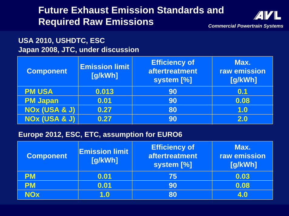
Future Exhaust Emission Standards andRequired Raw Emissions
Emission limit[g/kWh]
Max.raw emission
[g/kWh]
Efficiency ofaftertreatment
system [%]Component
0.013 0.190PM USA0.01 0.0890PM Japan0.27 1.080NOx (USA & J)0.27 2.090NOx (USA & J)
USA 2010, USHDTC, ESCJapan 2008, JTC, under discussion
Emission limit [g/kWh]
Max.raw emission
[g/kWh]
Efficiency ofaftertreatment
system [%]Component
0.01 0.0375PM0.01 0.0890PM1.0 4.080NOx
Europe 2012, ESC, ETC, assumption for EURO6

Commercial Powertrain Systems
EURO 4 – Emission Limits and Appertaining Raw Emissions
Legallimit
[g/kWh]
Engine rawemission[g/kWh]
Efficiency ofaftertreatment
system [%]Component
0.03 0.0430 *)PM
3.5 9.070 (SCR)NOx
Europe ETC, 2005 ( EURO4 )
*) Resulting from reduction of organic soluble particulate componentsby oxidative action of aftertreatment system

Commercial Powertrain Systems
4 4 -- 5 g/kWh NOx Raw Emission with NOx5 g/kWh NOx Raw Emission with NOx--Aftertreatment and Particulate Filter Aftertreatment and Particulate Filter
1 1 -- 2 g/kWh NOx Raw Emission with 2 g/kWh NOx Raw Emission with Exhaust Gas Recirculation, NOxExhaust Gas Recirculation, NOx--Aftertreatment and Particulate Filter Aftertreatment and Particulate Filter
Two Routes for Realising Various LowEmission Scenarios

Commercial Powertrain Systems
Fuel Injection System
Exhaust Gas Recirculation
Turbocharging
Cooling System
Control System
Engine Concepts:Engine Components Evaluated

Commercial Powertrain Systems
IntroductionIntroduction
EngineEngine--Out Emissions Required for Out Emissions Required for Various Emission StandardsVarious Emission Standards
Concept for 4 Concept for 4 -- 5 g/kWh NOx Raw 5 g/kWh NOx Raw EmissionsEmissions
Requirements on EGR Rate ControlRequirements on EGR Rate Control
Summary and ConclusionsSummary and Conclusions
Concept for 4 - 5 g/kWh NOx Raw Emissions

Commercial Powertrain Systems
80000
NOx NOx -- g/kWh g/kWh
PM
PM --
g/kW
hg/
kWh
2,02,0 6,06,04,04,0 8,08,0 10,010,00,00,0 1,01,0
0,080,08
0,060,06
0,040,04
0,020,02
0,010,01 Solution for bestfuel economy
Basic engine
Concepts forConcepts for NOx NOx = 4 = 4 -- 5 g/kWh 5 g/kWh Raw Raw Emission Emission and and ((assumedassumed) Legal Limit ) Legal Limit 1.01.0g/kWhg/kWh
η−DeNOx = 80 - 85 %η−DPF = 90 %
η−DeNOx = 80 - 85 %η−POC = 75 %
pinj = 2000 bar, low EGR ratehigh(er) swirl
pinj = 1600 bar,w/o EGRlow swirl

Commercial Powertrain Systems
IntroductionIntroduction
EngineEngine--Out Emissions Required for Out Emissions Required for Various Emission StandardsVarious Emission Standards
Concept for 1 Concept for 1 -- 2 g/kWh NOx Raw 2 g/kWh NOx Raw EmissionsEmissions
Requirements on EGR Rate ControlRequirements on EGR Rate Control
Summary and ConclusionsSummary and Conclusions
Concept for 1 - 2 g/kWh NOx Raw Emissions
Commercial Powertrain Systems
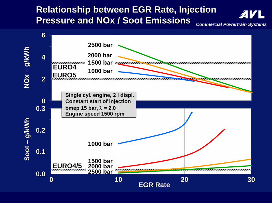
Relationship between EGR Rate, Injection Relationship between EGR Rate, Injection Pressure and Pressure and NOx /NOx / Soot EmissionsSoot Emissions
NO
x N
Ox
––g/
kWh
g/kW
h
00
22
44
66
EGR RateEGR Rate00 1010 3030
0.00.0
0.10.1
2020
0.20.2
0.30.3
Soot
So
ot ––
g/kW
hg/
kWh
Single cyl. engine, 2 l displ.Constant start of injectionbmep 15 bar, λ = 2.0Engine speed 1500 rpm
EURO4/5
EURO4EURO5
2500 bar
2500 bar
1000 bar
1000 bar
2000 bar
2000 bar
1500 bar
1500 bar

Commercial Powertrain Systems
Latest Development Results for Lowest Latest Development Results for Lowest Soot and NOx EngineSoot and NOx Engine--Out EmissionsOut Emissions
00
0,020,02
0,040,04
0,060,06
0,080,08
0,100,10
Soot
So
ot ––
g/kW
hg/
kWh
00
55
1010
1515
2020
2525
EGR
rate
EG
R ra
te ––
%%
00 11 22 33 44 55 66 77 88 99 1010NOx NOx –– g/kWhg/kWh
EURO4EURO5 B 75 ESC Load Point
Comb. System 1 pinj = 1800 barComb. System 2 pinj = 2000 barComb. System 3 pinj = 2500 bar
EGR
Soot
Commercial Powertrain SystemsB
MEP
B
MEP
––ba
rba
r
00
55
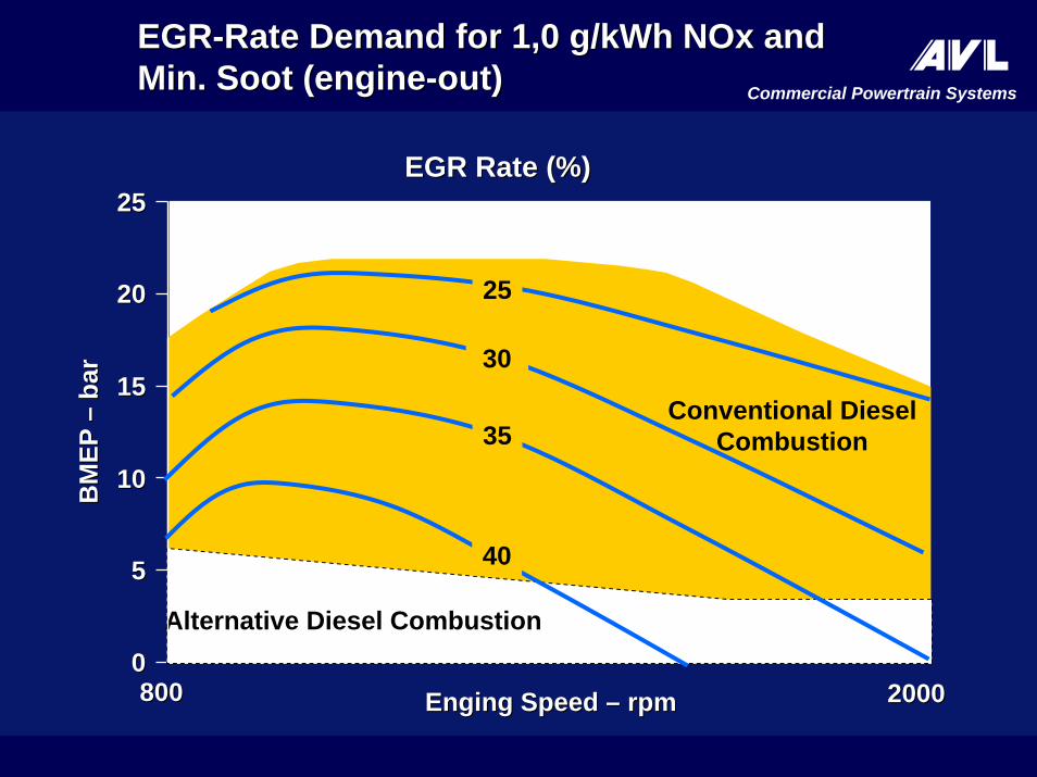
EGR Rate (%)EGR Rate (%)
800800 20002000
1010
1515
2020
2525
Alternative Diesel Combustion
Conventional DieselCombustion
30
40
35
25
EGREGR--Rate Rate Demand forDemand for 1,0 g/kWh1,0 g/kWh NOx andNOx andMin.Min. SootSoot ((engineengine--outout))
Enging Speed Enging Speed –– rpmrpm
Commercial Powertrain Systems
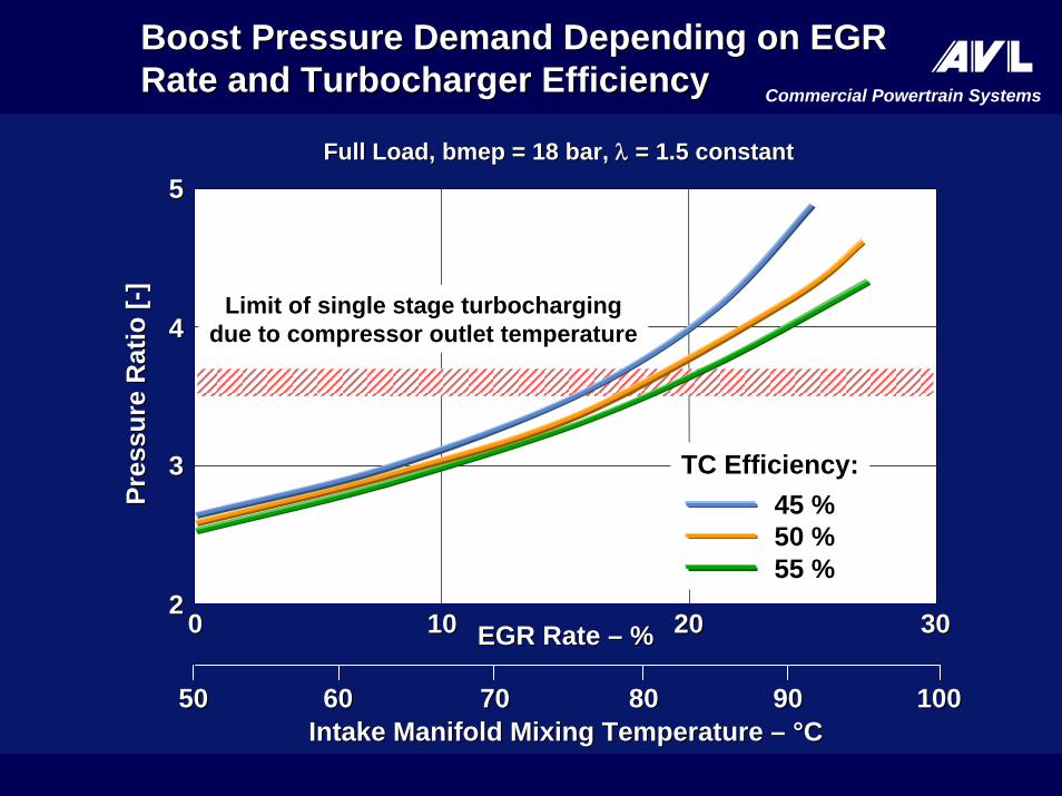
5050 90906060 80807070 100100Intake Manifold Mixing Intake Manifold Mixing Temperature Temperature –– °°CC
EGR EGR Rate Rate –– %%
Pres
sure
Pres
sure
Rat
io [
Rat
io [ --
]]
55
44
33
2200 1010 2020 3030
FullFull LoadLoad, , bmep bmep = 18 bar, = 18 bar, λλ = 1.5= 1.5 constantconstant
BoostBoost Pressure Demand DependingPressure Demand Depending on EGR on EGR Rate and Rate and Turbocharger EfficiencyTurbocharger Efficiency
Limit of single stage turbochargingdue to compressor outlet temperature
55 %50 %45 %
TC Efficiency:
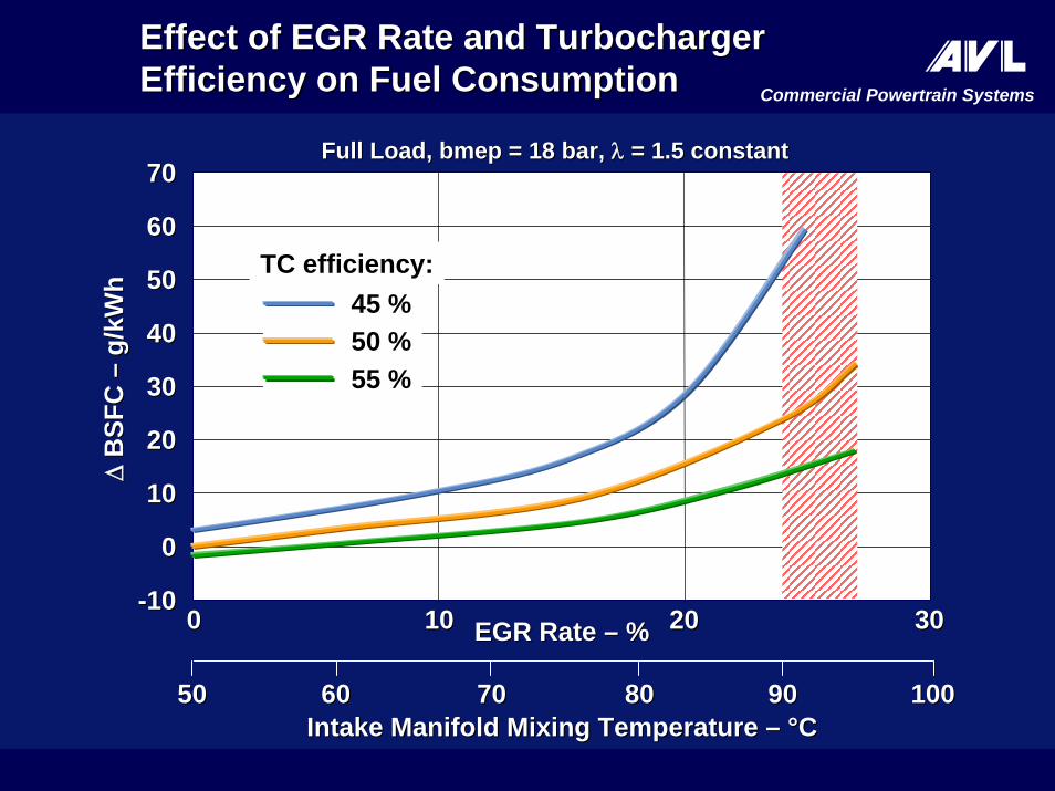
Commercial Powertrain Systems∆∆
BSF
C
BSF
C ––
g/kW
hg/
kWh
7070
6060
5050
4040
3030
2020
1010
00
--1010
5050 90906060 80807070 100100Intake Manifold Mixing Intake Manifold Mixing Temperature Temperature –– °°CC
EffectEffect of EGR Rate and of EGR Rate and Turbocharger Turbocharger EfficiencyEfficiency onon Fuel ConsumptionFuel Consumption
EGR EGR Rate Rate –– %%00 1010 2020 3030
55 %50 %45 %
TC efficiency:
FullFull LoadLoad, , bmep bmep = 18 bar, = 18 bar, λλ = 1.5= 1.5 constantconstant

Commercial Powertrain Systems
ESC C100 Punkt
EGR Rate EGR Rate –– %%
Hea
tH
eat r
ejec
tion
reje
ctio
n ––
kWkW
00 1010 2020 3030
EffectEffect of EGR Rate onof EGR Rate on HeatHeat RejectionRejection
12 l HD Diesel12 l HD Diesel engineengine, 350 kW, 350 kW classclass, , ESC C100 Point
Heat into EGR cooler
Total heat into coolant
300300
250250
200200
150150
100100
5050
00
400400
350350Total heat rejection
Heat into air intercoolers
Commercial Powertrain Systems
B 75 Lastpunkt
NOx NOx –– g/kWhg/kWh
PM
PM --
g/kW
hg/
kWh
2,02,0 6,06,04,04,0 8,08,0 10,010,00,00,0 1,01,0
0,080,08
0,060,06
0,040,04
0,020,02
0,010,01
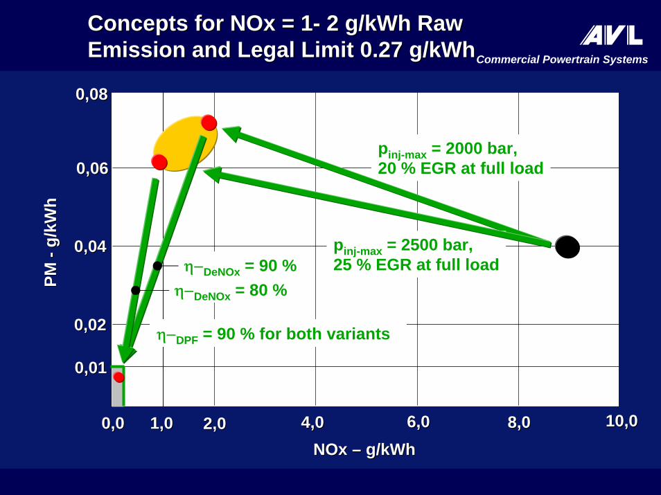
Concepts for NOxConcepts for NOx = = 11-- 2 g/kWh2 g/kWh RawRawEmissionEmission andand Legal Limit Legal Limit 0.270.27 g/kWhg/kWh
pinj-max = 2000 bar, 20 % EGR at full load
pinj-max = 2500 bar, 25 % EGR at full load
η−DPF = 90 % for both variants
η−DeNOx = 80 %η−DeNOx = 90 %

Commercial Powertrain Systems
IntroductionIntroduction
EngineEngine--Out Emissions Required for Out Emissions Required for Various Emission StandardsVarious Emission Standards
Engine ConceptsEngine Concepts
Requirements on EGR Rate ControlRequirements on EGR Rate Control
Summary and ConclusionsSummary and Conclusions
Requirements on EGR Rate Control

Commercial Powertrain Systems
EGR EGR Rate Rate –– %%00 1010 2020 3030
FullFull LoadLoad, , bmep bmep = 18 bar= 18 bar
NO
x N
Ox
––g/
kWh
g/kW
h
1010
88
66
44
22
00
∆∆N
Ox
NO
x ––
%%pe
r % E
GR
Rat
epe
r % E
GR
Rat
e
5050
4040
3030
2020
1010
00
Absolute and Relative Absolute and Relative EffectEffect ofofEGR Rate on NOxEGR Rate on NOx EmissionsEmissions
NOx
∆ NOx

Commercial Powertrain Systems
Engine Speed
Torq
ue
Heavy Duty EngineTo
rque
Engine Speed
PC / Light Duty Engine
EGR Rate Control Areas within Engine Mapof PassCar and HD Diesel Engines
EGR closed loopBoost pr. open loop
EGR open loopBoost pr. closed loop
Operating Area:EGR and boostpressure control demandin different map areas
EGR closed loopBoost pressure closed loop
Challenge:Necessity of simultaneous control of EGR rate andboost pressure
Operating Area:EGR and boost pressurecontrol demand in the same map area

Commercial Powertrain Systems
Boost press.Boost press.controllercontroller
EGREGRcontrollercontroller
AA singlesingle model based controller model based controller for for EGR rate andEGR rate and boost pressureboost pressureReciprocal influenceReciprocal influence of EGR of EGR rate and rate and boost pressure being boost pressure being taken into accounttaken into account in realin realengine operationengine operation
ResultResult::Better dynamic engine responseBetter dynamic engine responseControlControl of EGR rate andof EGR rate and boost boost pressure decoupledpressure decoupled to a highto a highextentextentReducedReduced ECUECU storage demandstorage demandandand application effortapplication effort
EmissionEmission reductionreductionFuel consumption improvementFuel consumption improvement
EngineEngine
VTGVTG ActuatorActuator BoostBoostPressurePressure
pprefref
EGR
EGR
Valv
eVa
lve
EGR
Rat
eEG
R R
ate
EGREGRrefref
ECUECU
ConceptConcept of Modelof Model BasedBased Controller Controller forfor EGR and VTGEGR and VTG

Commercial Powertrain Systems
EmissionEmission
Stationary optimized Stationary optimized emissionemission
TorqueTorque
EmissionEmission Improvement byImprovement by ModelModel BasedBasedControllerController during Transientsduring Transients
TimeTime
Standard Standard ControlControl: : EmissionEmission peak peak during during transientstransients
TorqueTorque
EmissionEmission
StationaryStationary optimized optimized emissionemission
Standard Standard ControlControl: : EmissionEmission peak peak during during transientstransients
TimeTime
MMCD dynamicMMCD dynamic optimizationoptimization of of load and emissionsload and emissions
Emis
sion
Emis
sion
Torq
ueTo
rque
MMCD: MMCD: MModelodel--Based Based MMultivariable ultivariable CController ontroller DDesignesign

Commercial Powertrain Systems
TransienTransien Emission Emission Reduction Reduction by AVL MMCD Controllerby AVL MMCD Controller

Commercial Powertrain Systems
IntroductionIntroduction
EngineEngine--Out Emissions Required for Out Emissions Required for Various Emission StandardsVarious Emission Standards
Engine ConceptsEngine Concepts
Requirements on EGR Rate ControlRequirements on EGR Rate Control
Summary and ConclusionsSummary and Conclusions
Summary and Conclusions
Commercial Powertrain Systems
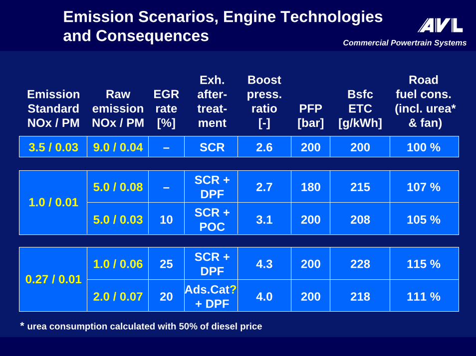
Emission Scenarios, Engine Technologies and Consequences
EmissionStandardNOx / PM
RawemissionNOx / PM
EGRrate[%]
Exh.after-treat-ment
Boostpress.ratio
[-]PFP[bar]
BsfcETC
[g/kWh]
Roadfuel cons.(incl. urea*
& fan)
3.5 / 0.03 9.0 / 0.04 – SCR 2.6 200 200 100 %
1.0 / 0.015.0 / 0.08 – SCR +
DPF 2.7 180 215 107 %
0.27 / 0.011.0 / 0.06 25 SCR +
DPF 4.3 200 228 115 %
111 %20 Ads.Cat?+ DPF 4.0 200 2182.0 / 0.07
105 %10 SCR +POC 3.1 200 2085.0 / 0.03
* urea consumption calculated with 50% of diesel price
Commercial Powertrain Systems
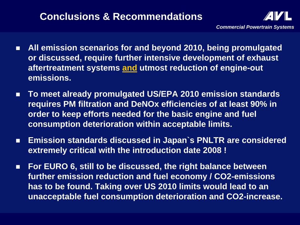
All emission scenarios for and beyond 2010, being promulgated or discussed, require further intensive development of exhaust aftertreatment systems and utmost reduction of engine-out emissions.
To meet already promulgated US/EPA 2010 emission standards requires PM filtration and DeNOx efficiencies of at least 90% inorder to keep efforts needed for the basic engine and fuel consumption deterioration within acceptable limits.
Emission standards discussed in Japan`s PNLTR are considered extremely critical with the introduction date 2008 !
For EURO 6, still to be discussed, the right balance between further emission reduction and fuel economy / CO2-emissions has to be found. Taking over US 2010 limits would lead to an unacceptable fuel consumption deterioration and CO2-increase.
Conclusions & Recommendations
Commercial Powertrain Systems
By 2010, fuel injection system manufacturers have to be preparedto volume supply of fully flexible injection systems with 2500 bar pressure capability.
Precise control of VTG and EGR rate requires a new approach, e.g. by means of model-based solutions.
Turbocharger manufacturers are highly challenged to develop turbochargers with total efficiencies of at least 55 %.
For cooling systems new approaches regarding enhanced efficiencies and compactness have to be found.
New quality control processes enabling the extreme narrowing of emission relevant production tolerances of the total system engine plus aftertreatment have to be developed and verified.
Conclusions & Recommendations (cont.)

Commercial Powertrain Systems
Lowest Engine-OutEmissions as the Key tothe Future of the Heavy-
Duty Diesel Engine:New Development Results
Franz X. MoserTheodor Sams, Rolf Dreisbach
AVL LIST GmbH, Austria
10th Diesel Engine Emission Reduction ConferenceAug. 30 – Sept. 2, 2004, San Diego

Commercial Powertrain Systems
HD Diesel HD Diesel Engine NOxEngine NOx andand PM Emission PM Emission DevelopmentDevelopment
Commercial Powertrain Systems
Emission Reduction Strategies
220
210
0 10NOx – g/kWh
4 6 8190
12 14
200
0.10
0.08
0.06
0
0.04
2
0.02
EURO
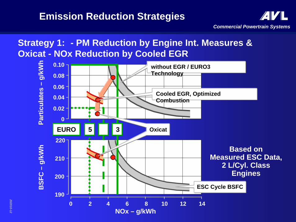
Strategy 1: - PM Reduction by Engine Int. Measures & Oxicat - NOx Reduction by Cooled EGR
5
ESC Cycle BSFC
without EGR / EURO3 Technology
3 Oxicat
Cooled EGR, OptimizedCombustion
Based onMeasured ESC Data,
2 L/Cyl. Class Engines
BSF
C –
g/kW
hPa
rtic
ulat
es –
g/kW
h
202010-12

Commercial Powertrain SystemsEmission Reduction StrategiesEmission Reduction Strategies
202010-10
220
210
0 10NOx – g/kWh
4 6 8190
12 14
200
0.10
0.08
0.06
0
0.04
2
0.02
EURO
Strategy 2:Strategy 2: -- NOxNOx Reduction by Exhaust Gas Reduction by Exhaust Gas RecirculationRecirculation -- PM Reduction by Particulate TrapPM Reduction by Particulate Trap
Based onBased onMeasured ESC Data,Measured ESC Data,
2 L/2 L/CylCyl. Class . Class EnginesEngines
45
ESC Cycle BSFC
without EGR / EURO3 Technology
Cooled EGR + Optimized Combustion
Trap
3
BSF
C –
g/kW
hPa
rtic
ulat
es –
g/kW
h

Commercial Powertrain SystemsEmission Reduction StrategiesEmission Reduction Strategies
220
210
0 10NOx – g/kWh
4 6 8190
12 14
200
0.10
0.08
0.06
0
0.04
2
0.02
EURO
StrategyStrategy 3:3: -- PM Reduction by Engine Internal MeasuresPM Reduction by Engine Internal Measures-- NOxNOx Reduction by Exhaust GasReduction by Exhaust Gas AftertreatmentAftertreatment
Based onBased onMeasured ESC Data,Measured ESC Data,
2 L/2 L/CylCyl. Class Engines. Class Engines
45
ESC Cycle BSFC
without EGR / EURO3 Technology
>65% Efficiency SRC>80%3
Combustion Optimized for min. Soot
BSF
C –
g/kW
hPa
rtic
ulat
es –
g/kW
h
202010-11

Commercial Powertrain SystemsEmission Reduction StrategiesEmission Reduction Strategies
220
210
0 10NOx – g/kWh
BSF
C –
g/kW
h
4 6 8190
12 14
200
0.10
0.08
0.06
0
0.04
Part
icul
ates
–g/
kWh
2
0.02
Strategy 4:Strategy 4: -- Combination of all Technologies, i.e.Combination of all Technologies, i.e.CombustionCombustion OptimizationOptimization, , DeNOx DeNOx & PM& PM AftertreatmentAftertreatment
Based onBased onMeasured & ProjectedMeasured & Projected
ESC Data,ESC Data,2 L/2 L/CylCyl. Class Engines. Class Engines
ESC Cycle BSFC
without EGR / EURO3 Technology
Cooled EGR, Optimized Combustion
US 2010 >65% Efficiency DeNOx>90%US 2007
Trap
202010-13

100%100%
Engi
ne to
rque
Engi
ne to
rque
Engine speedEngine speed 100%100%00
JTCJTC
Low idle 32%Low idle 32%
Motoring 19%Motoring 19%
ETCETC
Low idle 8%Low idle 8%
Motoring 15%Motoring 15%
US TCUS TC
Low idle 35%Low idle 35%
Motoring 16%Motoring 16%
Main Operating Areas in Emission CyclesMain Operating Areas in Emission CyclesUSA, Europe, JapanUSA, Europe, Japan

Commercial Powertrain SystemsAdvanced Combustion Development
Development Strategies
for
US 2007 / 2010
Commercial Powertrain Systems
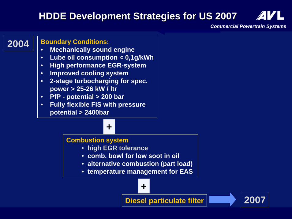
Boundary Conditions:• Mechanically sound engine• Lube oil consumption < 0,1g/kWh• High performance EGR-system• Improved cooling system• 2-stage turbocharging for spec.
power > 25-26 kW / ltr• PfP - potential > 200 bar• Fully flexible FIS with pressure
potential > 2400bar
HDDEHDDE Development Strategies for US Development Strategies for US 20072007
2004
2007
Combustion system• high EGR tolerance• comb. bowl for low soot in oil• alternative combustion (part load)• temperature management for EAS
+
+Diesel particulate filter

Commercial Powertrain SystemsHDDE Development Strategies for US HDDE Development Strategies for US 20102010
2007
2010
+
US 2007development
De-NOx systemdevelopment
and integration

Commercial Powertrain Systems
Boundary Conditions:• Mechanically sound Engine• Lube oil consumption < 0,1g/KWh• High performance EGR-system• Improved cooling system• 2-stage turbocharging > 25-27 kW/l• PfP - potential > 200 bar• Fully flexible FIS, press. potential >
2000bar
HDDEHDDE Development Strategies for US Development Strategies for US 20072007
2004
2007
Route 1 Route 2
• Highly EGR-tolerant comb. system • Comb. bowl for low soot in oil• Alternative combustion (part load)• Temperature management for EAS
+
+Diesel particulate filter
Boundary Conditions:• Mechanically restricted engine design• lube oil consumption > 0,1g/kWh• PfP - potential < 170 bar• Limited FIS , press. potential < 1600bar
• Combustion system with no (or low) EGR tolerance
• Comb. bowl for low soot in oil• Alternative combustion (part load)• Temperature management for EAS
De-NOx system and Diesel particulate filter
+
+
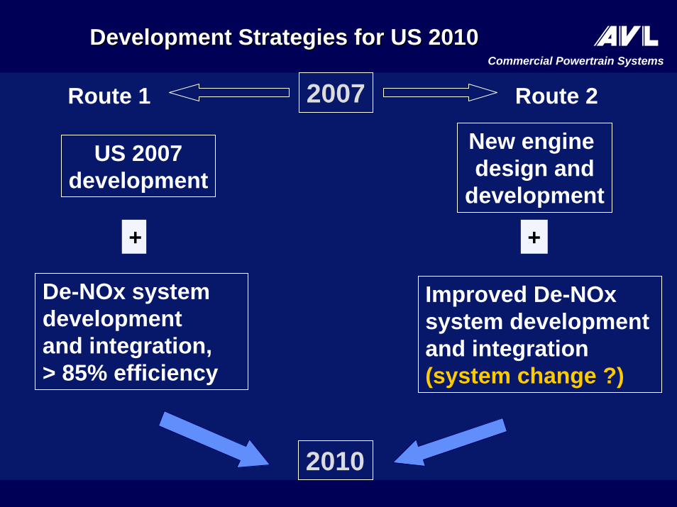
Commercial Powertrain SystemsDevelopment Strategies for US 2010Development Strategies for US 2010
2007
2010
Route 1 Route 2
+ +
US 2007development
De-NOx systemdevelopmentand integration,> 85% efficiency
New engine design and
development
Improved De-NOxsystem development and integration(system change ?)

Commercial Powertrain Systems
0,1
1
10
1000 1500 2000 2500 3000
Local Flame Temperature [K]
Loca
l Air
Exce
ss R
atio
[-]
Soot
NOx
TodayToday´́ssTechnologiesTechnologies
AlternativeCombustion
Systems
Diesel Combustion Systems for Low NOx/Soot Diesel Combustion Systems for Low NOx/Soot EmissionEmission

Commercial Powertrain Systems
NEDC Simulation NEDC Simulation withwith Alternative Alternative CombustionCombustion
NEDC Simulation NEDC Simulation -- 2,2 L HSDI Diesel Engine in 1590 kg ITW 2,2 L HSDI Diesel Engine in 1590 kg ITW Vehicle.Vehicle.
NOxNOx ReductionReduction SootSoot ReductionReduction
g/km %g/km % g/km %g/km %
Standard CombustionStandard Combustion 0,2300,230 -- 0,020 0,020 --
Combined Standard &Combined Standard & AlternativeAlternative Combustion 0,093 Combustion 0,093 60600,006 0,006 7070
Simulation based on Single Cylinder Test ResultsSimulation based on Single Cylinder Test Results

Commercial Powertrain SystemsModelModel--based Exhaust Emission Control based Exhaust Emission Control
Sensor dataSensor data
Engine Management
Vehicle Steady Vehicle Steady State Driving State Driving
ConditionCondition
* NOx* NOx--Adsorber, Particulate Filter, ...Adsorber, Particulate Filter, ...
Sensor dataSensor data
Model dataModel data
Observer
Exhaust SystemModel
Exhaust System* Exhaust System* Raw EmissionsRaw Emissions[NO[NOx,x,HC,CO, ...]HC,CO, ...]
EmissionModel
Observer
AVLAVLExhaust Exhaust System*System*
ManagementManagement

Commercial Powertrain Systems
Solving the SootSolving the Soot--InIn--OilOil Problem: Problem: Effect of Combustion Bowl ShapeEffect of Combustion Bowl Shape
Traditional B
owl Shape
New Bowl Shape
00 55 1010 1515 2020 2525 3030
Inso
lubl
es (S
oot
Inso
lubl
es (S
oot -- i
nin-- O
il)
Oil)
––%%
0.350.35
0.300.30
0.250.25
0.200.20
0.150.15
0.100.10
0.050.05
00
Running Time of SootRunning Time of Soot--inin--Oil ESC Test Procedure Oil ESC Test Procedure –– hourshours
1.01.0
0.50.5
0.250.25
0.10.1
1.51.5Oil Soot Growth Rate Oil Soot Growth Rate –– % / 100h% / 100h
Medium Duty EURO3 Engine30 kW/liter, 4 Valves/Cyl.Common Rail FIEw/o Oil Centrifuge
202018-01
Commercial Powertrain Systems
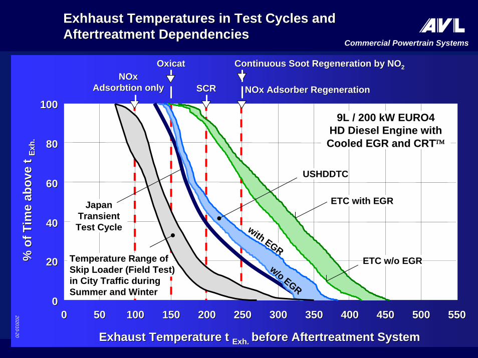
OxicatOxicatNOx NOx
Adsorbtion onlyAdsorbtion only SCRSCR
Continuous Soot Regeneration by NOContinuous Soot Regeneration by NO22
NOx Adsorber RegenerationNOx Adsorber Regeneration
ExhhaustExhhaust TemperaturesTemperatures in Test in Test Cycles and Cycles and AftertreatmentAftertreatment Dependencies Dependencies
00 5050 100100 150150 200200 250250 300300 350350 400400 450450 500500 55055000
2020
4040
6060
8080
100100
Exhaust Temperature t Exhaust Temperature t Exh. Exh. before Aftertreatment System before Aftertreatment System
% o
f Tim
e ab
ove
t %
of T
ime
abov
e t Ex
h.Ex
h.
ETC w/o EGR
ETC with EGR
USHDDTC
with EGR
w/o EGR
9L / 200 kW EURO4 HD Diesel Engine with Cooled EGR and CRT™
Japan TransientTest Cycle
202010-20
Temperature Range of Skip Loader (Field Test)in City Traffic during Summer and Winter

Commercial Powertrain Systems
5050
4545
4040
3535
3030Mea
n Fu
el C
onsu
mpt
ion
Mea
n Fu
el C
onsu
mpt
ion
––l /
100
kml /
100
km
19701970 19801980 19901990 20002000 20102010YearYear19741974
Mittlerer Kraftstoffverbrauch Mea
n D
rivin
g Sp
eed
Mea
n D
rivin
g Sp
eed
––km
/hkm
/h
9090
8080
7070
6060
5050
4040
Nutzfahrzeuge mit 38 – 40 t und
Dieselmotorenhoher Leistung
Mittlere Fahrgeschwindigkeit
Mittlere Motorleistung
(kW)220
347
230
283 286 310
426
HD Diesel HD Diesel TechnologiesTechnologies 1974 1974 –– 20102010Truck Truck Fuel Consumption and SpeedFuel Consumption and Speed
Quelle: Quelle: lastauto omnibuslastauto omnibus

Commercial Powertrain Systems
FutureFuture Truck Diesel Truck Diesel EngineEngine22--Stage Turbocharging Stage Turbocharging DesignDesign

Commercial Powertrain Systems
Filter Volume 25 Filter Volume 25 LiterLiter; Max. Acceptable Ash Content 75g / ; Max. Acceptable Ash Content 75g / Liter Liter Filter Filter Volume Volume
0.00.0
0.50.5
1.01.0
1.51.5
2.02.0
0.00.0 0.250.25 0.50.5 0.750.75 1.01.0 1.251.25 1.51.5LOC LOC –– kg/1000kmkg/1000km
Mai
nten
ance
Inte
rval
M
aint
enan
ce In
terv
al ––
Mio
km
Mio
km
OAC = 0.5%1%2%
Maintenance Interval as a function of Oil Ash Content (OAC)Maintenance Interval as a function of Oil Ash Content (OAC)and Lube Oil Consumption (LOC)and Lube Oil Consumption (LOC)
202010-23
(12 / 14 Ltr. Swept volume)
LubeLube--Oil Ash Deposits and DPF Maintenance Oil Ash Deposits and DPF Maintenance Intervals Intervals

Commercial Powertrain Systems
Flow Through Non-Blocking PM Catalyst
Test Arrangement for 6.6L / 228 KW HD Diesel Engine
Mechanism and Effectiveness:Carbon-PM oxidized by NO2
being formed in Oxicat
HC, Sol-PM and CO oxidized in Oxicat
Conversion Rates (ESC & ETC):ηPM ≈ 50%, target 70% by further
developmentηHC ≈ 85%ηCO ≈ 90%
Principle of Particle Deposition in Porous Smooth Section of Mixing Section
Source: Emitec GmbH & MAN Nutzfahrzeuge AG
150 mm
Oxicat
5 PM catalysts in quick-exchange housing
202010-24

Commercial Powertrain Systems
Principle of Particle Depositing in a Porous Flat Foil of the Mixing Section