lowering the limits for earth-fault detection -...
TRANSCRIPT
Lowering the Limits for Earth-Fault DetectionM. Savostianik, EIT
Littelfuse Startco3714 Kinnear Place
Saskatoon, SaskatchewanCanada S7P 0A6
Abstract—Current flowing to earth has only twopaths—it can flow to earth through an earth fault, andit can flow to earth through distributed capacitance.Current flowing to earth through distributedcapacitance can cause sympathetic tripping during anearth fault and it can cause nuisance tripping duringnormal operation. If the earth-fault trip level is highenough to eliminate sympathetic tripping, nuisancetripping due to unbalanced and harmonic capacitivecurrent is usually not a problem. However, ifsympathetic tripping is not a concern and earth-faulttrip levels are lowered, nuisance tripping can becomea problem that worsens with the increased use ofadjustable-speed drives. This paper discusses thesources of current flowing to earth that are not theresult of an earth fault, and it shows how a digitalfilter tuned to the fundamental component of earth-fault current can provide lower trip levels withoutnuisance tripping.
The limit to practical low-level earth-fault protection inindustrial electrical systems is a function of physicalparameters. Current sensing is the best method to detectand locate earth faults; however, system capacitance,unbalanced loads, current-sensor limitations, andharmonics affect current measurement and limit the lowerlevel of practical earth-fault detection. Earthed systemsare presumed in the following discussion on limitingfactors and the techniques that can be implemented tomitigate them.
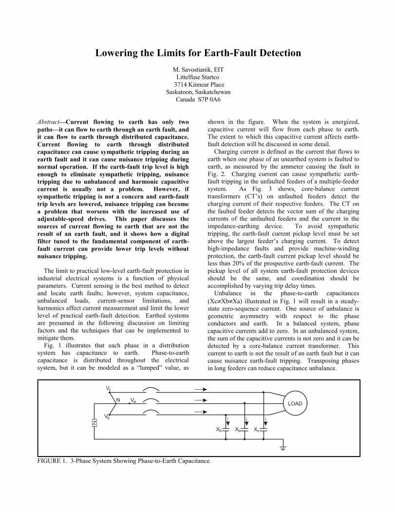
Fig. 1 illustrates that each phase in a distributionsystem has capacitance to earth. Phase-to-earthcapacitance is distributed throughout the electricalsystem, but it can be modeled as a “lumped” value, as
shown in the figure. When the system is energized,capacitive current will flow from each phase to earth.The extent to which this capacitive current affects earth-fault detection will be discussed in some detail.
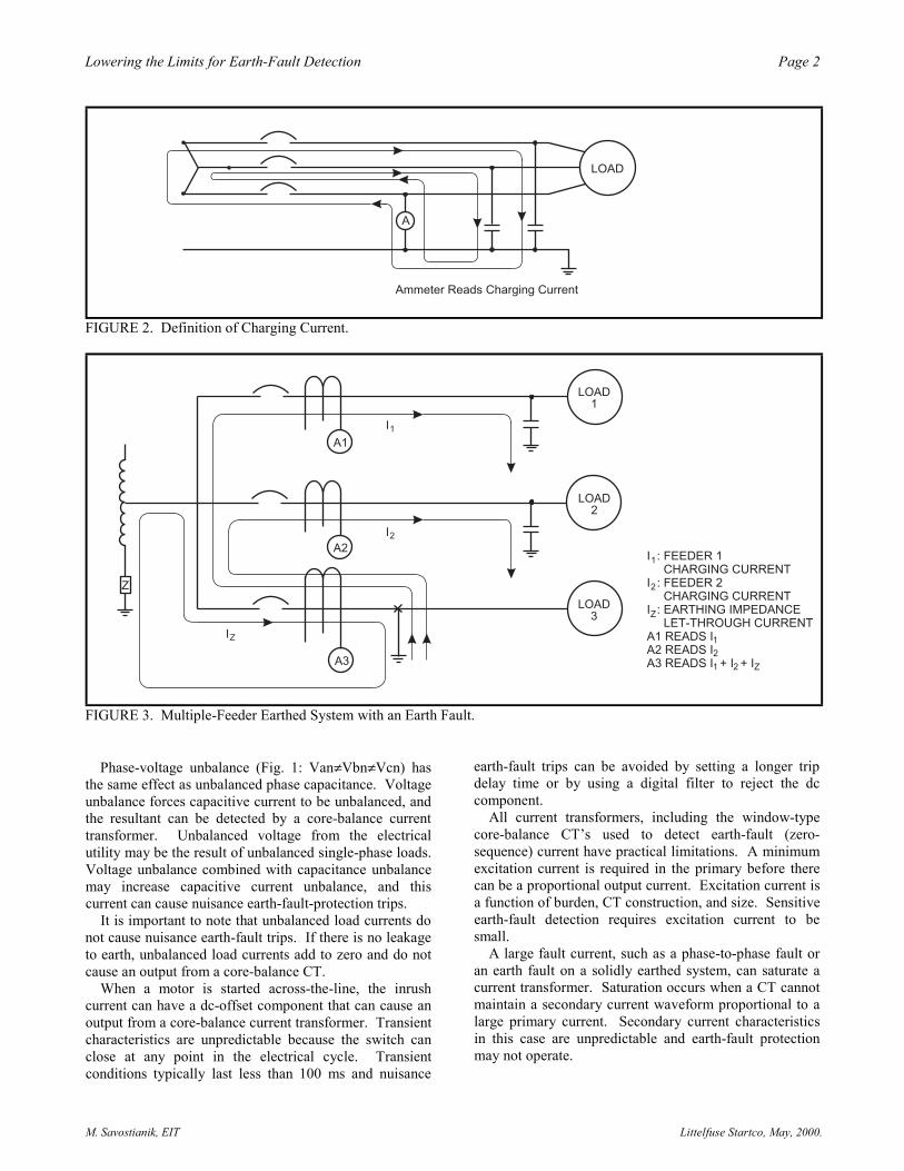
Charging current is defined as the current that flows toearth when one phase of an unearthed system is faulted toearth, as measured by the ammeter causing the fault inFig. 2. Charging current can cause sympathetic earth-fault tripping in the unfaulted feeders of a multiple-feedersystem. As Fig. 3 shows, core-balance currenttransformers (CT’s) on unfaulted feeders detect thecharging current of their respective feeders. The CT onthe faulted feeder detects the vector sum of the chargingcurrents of the unfaulted feeders and the current in theimpedance-earthing device. To avoid sympathetictripping, the earth-fault current pickup level must be setabove the largest feeder’s charging current. To detecthigh-impedance faults and provide machine-windingprotection, the earth-fault current pickup level should beless than 20% of the prospective earth-fault current. Thepickup level of all system earth-fault protection devicesshould be the same, and coordination should beaccomplished by varying trip delay times.
Unbalance in the phase-to-earth capacitances(Xc≠Xb≠Xa) illustrated in Fig. 1 will result in a steady-state zero-sequence current. One source of unbalance isgeometric asymmetry with respect to the phaseconductors and earth. In a balanced system, phasecapacitive currents add to zero. In an unbalanced system,the sum of the capacitive currents is not zero and it can bedetected by a core-balance current transformer. Thiscurrent to earth is not the result of an earth fault but it cancause nuisance earth-fault tripping. Transposing phasesin long feeders can reduce capacitance unbalance.
FIGURE 1. 3-Phase System Showing Phase-to-Earth Capacitance.
2 egaPnoitceteD tluaF-htraE rof stimiL eht gnirewoL
M. Savostianik, EIT Littelfuse Startco, May, 2000.
FIGURE 2. Definition of Charging Current.
FIGURE 3. Multiple-Feeder Earthed System with an Earth Fault.
Phase-voltage unbalance (Fig. 1: Van≠Vbn≠Vcn) hasthe same effect as unbalanced phase capacitance. Voltageunbalance forces capacitive current to be unbalanced, andthe resultant can be detected by a core-balance currenttransformer. Unbalanced voltage from the electricalutility may be the result of unbalanced single-phase loads.Voltage unbalance combined with capacitance unbalancemay increase capacitive current unbalance, and thiscurrent can cause nuisance earth-fault-protection trips.
It is important to note that unbalanced load currents donot cause nuisance earth-fault trips. If there is no leakageto earth, unbalanced load currents add to zero and do notcause an output from a core-balance CT.
When a motor is started across-the-line, the inrushcurrent can have a dc-offset component that can cause anoutput from a core-balance current transformer. Transientcharacteristics are unpredictable because the switch canclose at any point in the electrical cycle. Transientconditions typically last less than 100 ms and nuisance
earth-fault trips can be avoided by setting a longer tripdelay time or by using a digital filter to reject the dccomponent.
All current transformers, including the window-typecore-balance CT’s used to detect earth-fault (zero-sequence) current have practical limitations. A minimumexcitation current is required in the primary before therecan be a proportional output current. Excitation current isa function of burden, CT construction, and size. Sensitiveearth-fault detection requires excitation current to besmall.
A large fault current, such as a phase-to-phase fault oran earth fault on a solidly earthed system, can saturate acurrent transformer. Saturation occurs when a CT cannotmaintain a secondary current waveform proportional to alarge primary current. Secondary current characteristicsin this case are unpredictable and earth-fault protectionmay not operate.
3 egaPnoitceteD tluaF-htraE rof stimiL eht gnirewoL
M. Savostianik, EIT Littelfuse Startco, May, 2000.
Surge currents and conductor placement can lead tolocal saturation in a core-balance CT. Local saturationcan cause a core-balance CT secondary output when nozero-sequence current exists, leading to a nuisance trip.Surge currents can be as high as 160% locked-rotorcurrent for motors. Phase conductors should be centeredin the CT window, and multi-conductor circuits should bebundled ABC, ABC, etc., not AA, BB, CC, etc., as shownin Fig. 4. The use of a flux conditioner, a ring ofmagnetically conductive material inserted in the CTwindow, can reduce local saturation.
FIGURE 4. Core-Balance Transformer CableArrangements.
The presence of harmonic-frequency voltages (integermultiples of the fundamental frequency) in an electricalsystem cause harmonic-frequency currents that can affectearth-fault detection and minimum trip set points.Harmonics can be the result of the use of adjustable-speeddrives (ASD) and solid-state starters. Static switching ofline currents cause harmonic voltages that driveharmonic-capacitive current from the phases to earth.Capacitive impedance is inversely proportional tofrequency (Xc = 1/(2πfC) where f = frequency in Hertz).The higher the frequency, the lower the capacitiveimpedance, and the greater the current per volt. Exceptfor the triplens, harmonic currents to earth add in thesame manner as the fundamental components ofcapacitive current to earth. That is, only the unbalance ineach harmonic contributes to neutral current.
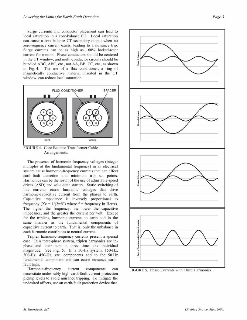
Triplen harmonic-frequency currents present a specialcase. In a three-phase system, triplen harmonics are in-phase and their sum is three times the individualmagnitude. See Fig. 5. In a 50-Hz system, 150-Hz,300-Hz, 450-Hz, etc. components add to the 50 Hzfundamental component and can cause nuisance earth-fault trips.
Harmonic-frequency current components cannecessitate undesirably high earth-fault current-protectionpickup levels to avoid nuisance tripping. To mitigate theundesired affects, use an earth-fault protection device that
Phas
e A
Cur
rent
Phas
e B
Cur
rent
Phas
e C
Cur
rent
Sum
of F
unda
men
tal &
Trip
len
Cur
rent
s
FIGURE 5. Phase Currents with Third Harmonics.

4 egaPnoitceteD tluaF-htraE rof stimiL eht gnirewoL
M. Savostianik, EIT Littelfuse Startco, May, 2000.
ignores dc-offset and harmonic-frequency current, andresponds only to the fundamental-frequency componentof current. The filtering characteristic must be fast toallow a short earth-fault trip time.
Digital filtering of the zero-sequence-current waveformprovides a fast and accurate solution to many low-levelearth-fault detection problems. Digital sampling anddigital signal processing techniques can be used toconstruct a band-pass filter that responds to onlythe fundamental-frequency component—dc-offset andharmonic components are ignored. The discrete Fouriertransform (DFT) algorithm is a mathematical tool that canquickly extract a specific-frequency signal from amultiple-frequency signal. The example shown in Fig. 6is a 50-Hz signal with a 150-Hz third-harmoniccomponent. The simplified DFT algorithm is:
∑−
=×=
1
0)2sin()(2 m
n mnnI
mIp π
Where: Ip = peak currentm = number of samples per cyclen = sample numberI(n) = measured sample
The sampler is set to take a known number of samplesper cycle of the desired frequency. In the example thefilter is tuned to 50-Hz by selecting a sample frequency of1 kHz (20 samples per cycle). The example summationis:
∑=
×=19
0)
202sin()(
202
n
nnIIp π
Ip = 1.414
-2
-1.5
-1
-0.5
0
0.5
1
1.5
2
0 1 2 3 4 5 6 7 8 9 10 11 12 13 14 15 16 17 18 19 20
Time (ms)
Am
pere
s
50 Hz Component 150 HzComponent EF Current Waveform Samples
FIGURE 6. Earth-Fault Current with Fundamental and Harmonic Components.

5 egaPnoitceteD tluaF-htraE rof stimiL eht gnirewoL
M. Savostianik, EIT Littelfuse Startco, May, 2000.
Table 1 shows the values, from the example in Fig. 6,of the 50 Hz component, the 150 Hz component, and theearth-fault current that is the sum of the two, at each ofthe sample times, n. It also shows the sample-time DFT-component value of both the 50 Hz component and of thesample, and the sum of each over the sample period ofn=0 to n=19. Note that the sum for the fundamentalcomponent is the same as the sum for the sampledwaveform, showing that this sampling technique hasprovided an accurate measurement of the fundamentalcomponent in spite of the presence of the 150 Hz thirdharmonic.
Note that only a single cycle of the fundamentalcomponent is required for the calculation, here 1/50th
second, or 20 ms. Thereafter, the value is updated every
millisecond and the value is accurate, based on theprevious 20 samples.
Earth-fault protection relays that use digital filtering-techniques can reduce nuisance tripping associated withlow-level protection. Such devices ignore the dccomponent when a motor starts, and allow lower tripcurrent and trip time set points. Protection that uses DFTfiltering ignores harmonic components of zero-sequencecurrent that results from capacitive unbalance, againallowing a lower trip set point. Triplen harmoniccomponents, whose phase values are additive, are filteredby the DFT algorithm both in terms of capacitance-unbalance current and earth-fault current, againpermitting the selection of a lower current trip level, andthe one-cycle DFT calculation time allows a rapid triptime.
TABLE 1. COMPONENT AND DFT VALUES.
SAMPLENUMBER
(n)
50 HzCOMP.
If(n)
150 HzCOMP.
SAMPLEDVALUE
I(n)
If(n)sin(2*pi*n/20) I(n)sin(2*pi*n/20)
0 0.000 0.000 0.000 0.000 0.0001 0.437 0.381 0.818 0.135 0.2532 0.831 0.448 1.280 0.489 0.7523 1.144 0.146 1.290 0.926 1.0434 1.345 -0.277 1.068 1.279 1.0165 1.414 -0.471 0.943 1.414 0.9436 1.345 -0.277 1.068 1.279 1.0167 1.144 0.146 1.290 0.926 1.0438 0.831 0.448 1.280 0.489 0.7529 0.437 0.381 0.818 0.135 0.253
10 0.000 0.000 0.000 0.000 0.00011 -0.437 -0.381 -0.818 0.135 0.25312 -0.831 -0.448 -1.280 0.489 0.75213 -1.144 -0.146 -1.290 0.926 1.04314 -1.345 0.277 -1.068 1.279 1.01615 -1.414 0.471 -0.943 1.414 0.94316 -1.345 0.277 -1.068 1.279 1.01617 -1.144 -0.146 -1.290 0.926 1.04318 -0.831 -0.448 -1.280 0.489 0.75219 -0.437 -0.381 -0.818 0.135 0.253
14.142 14.142