lowering coal-fired nox through robust...
TRANSCRIPT

LOWERING COAL-FIRED NOx THROUGH ROBUST HYBRID COMBUSTION OPTIMIZATION
Jim Stewart
LaCygne Station, Kansas City Power & Light Co., U.S.A
Dr. Sudha Thavamani Siemens Energy, Instrumentation, Controls & Electrical, U.S.A
Till Spaeth
Siemens Energy, Instrumentation, Controls & Electrical, Germany
Abhijit Sarma Siemens Energy, Instrumentation, Controls & Electrical, U.S.A
Bruce Kelly
Sega Inc., U.S.A
Keywords:
Combustion Optimization, Low Emissions, Wall Fired Boiler, Siemens Power Plant Automation SPPA-P3000, Laser based Measurement, Non-linear Optimization based on Neural Networks
ABSTRACT In the current market conditions, steam power plants must always be run at the most profitable operating point. This primarily demands low emissions and the most cost efficient way to minimize emissions is to optimize the combustion process. The Siemens SPPA-P3000 process optimization solutions allow plant operators to achieve these objectives. This paper describes an online robust Combustion Optimization methodology used at LaCygne Unit 2 power plant of Kansas City Power and Light (KCPL) to significantly reduce NOx emissions on a 30-plus-year-old 720 MW B&W wall-fired boiler firing 100 percent powder river basin coal. The Siemens SPPA-P3000 Combustion Optimization solutions were employed on the boiler without over-fired air by utilizing the existing combustion equipment, existing combustion controls system, and a new in-furnace laser based combustion monitoring system. The Combustion Optimizer provides closed-loop optimization of fuel and air combination by maneuvering the appropriate fuel and air flows in the furnace. This paper elaborates the hybrid of model based controls with neural network optimization technology, its implementation and operational results.
INTRODUCTION The ever- rising demand for cost-efficient power generation and tough environmental regulation has motivated implementation of process optimization strategies in coal-fired power generation during the recent few years. Coal is a vital constituent of the energy source in the United States, process optimization for stack emission reductions and efficiency improvements in coal-fired boilers and plays a significant function in minimizing operational and maintenance (O&M) costs, and maximizing performance and unit availability. One area receiving major interest is optimization of the combustion process for nitrogen oxides (NOx) emission. The investigations of the characteristics of NOx formation have facilitated scientists and engineers to develop control methodologies for reducing NOx emissions in fossil-fuel power plants. The preliminary research has concentrated principally on controlling NOx at the source as NOx is formed during the combustion process. This is referred to as combustion control or in-furnace NOx reduction techniques. NOx formation is promoted by rapid fuel-air mixing resulting from high peak flame temperatures and excess oxygen. Combustion modifications offer the most cost-effective step in controlling a number of pollutants in addition to NOx. Advancement of guiding principles and premium practices, data from full-scale demonstrations, and evaluation of flourishing technologies present crucial information to formulate knowledgeable decisions. Value to members may comprise of the capability to take advantage of the anticipated NOx credit market and avoidance of higher-cost emissions controls. Siemens SPPA – P3000 Combustion Optimization is a technique proven for reducing NOx emissions from coal-fired boilers for enabling industrial compliance with today’s regulatory requirements. The Combustion Optimizer provides closed-loop optimization of fuel and air mixing by manipulating fuel and air levels to balance combustion in the furnace. The paper describes in detail the emission improvements achieved by using the Combustion Optimizer at LaCygne Unit 2 of Kansas City Power and Light (KCPL). The combustion optimizer is a hybrid of model based controls with neural network optimization technology. The control approach together with the operational results is presented. LACYGNE POWER PLANT UNIT 2 BOILER DESCRIPTION
LaCygne Unit 2 Power Plant of Kansas City Power & Lighting (KCPL) is located in LaCygne, KS. It a 30-plus-year-old 720 MW B&W wall-fired boiler firing 100 percent powder river basin coal. La Cygne Unit 2 is a balance draft, Carolina type radiant B&W wall fired unit. It has 7 MPS-89 pulverizers and 56 B&W 2nd generation dual register type low Nox burners. It does not have an OFA system. There are seven coal feeders and mills. At each level there are eight burners. There are 14 independently controllable air flows.

COMBUSTION OPTIMIZATION PROJECT EXECUTION
The combustion optimization project was executed between 2011-2012 timeframe with four major steps as shown in the Figure 1.
1. The first step was the installation of laser measurement grids inside the Boiler.
2. The second step was to carry out parametric testing based on the conditions of the boiler. This was followed by the deductions and analysis of the spatial distributions.
3. Based on observations and inferences of step 2 above, decision on the required controlled
variables for the closed loop controls engineering was made, which was the third major step of the project.
4. The fourth step was to integrate and commission the SPPA-P3000 Combustion
Optimization controls in the existing I&C system.
Figure 1 Combustion Optimization Project Execution at LaCygne Unit 2 Power Plant
SIEMENS SPPA – P3000 COMBUSTION OPTIMIZER DESCRIPTION
The Siemens Combustion Optimizer is software based solutions and does not require any modifications to mechanical equipment. The solution comprises of Combustion Optimizer modules for laser-based measuring technology, distribution calculation based on Computer-Aided Tomography (CAT) procedure, a standard imaging method from the field of medical technology, and Combustion Optimization Controls as shown in Figure 2. At LaCygne Unit 2, the combustion

optimize was completely integrated with the included spectroscopy-based in-furnace measurements system.
Figure 2 Combustion Optimizer Module Interactions
The laser-based measurement system maps the concentration of in-furnace CO, O2, H2O and temperature simultaneously in real time and directly in the furnace as shown in Figure 3. Laser transmitters and receivers are arranged outside the boiler resulting in a grid of laser beams criss-crossing the furnace. Each path measures an average value for temperature, O2, H2O, and CO simultaneously, and together, the paths are used to create a tomographic image of this plane in the boiler, which is also displayed to the operators directly in the control room.
Figure 3 Laser –based Measurement System
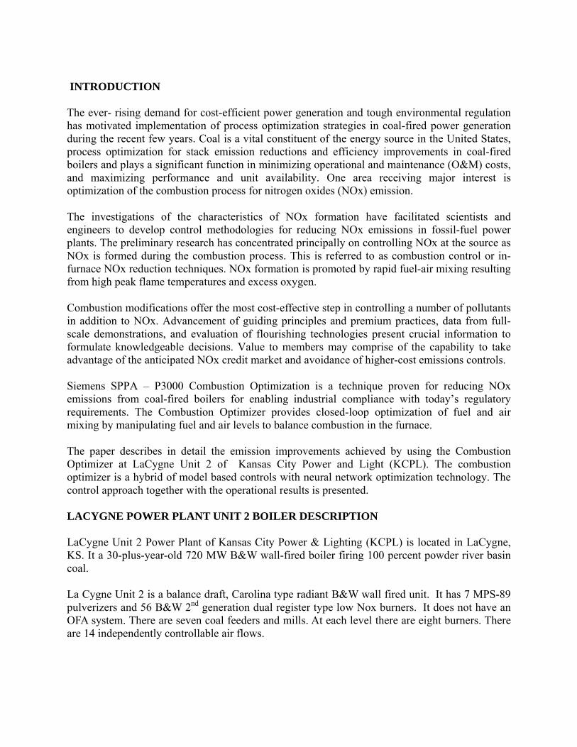
The temperature and concentration distributions are calculated from the measured path averages
with the aid of the CAT procedure. This calculation is performed on the thin client as shown in Figure 4. CAT algorithm is also used for calculating certain characteristic distribution data, e.g. values at different grid points, averages, minimum and maximum values for different paths in the distribution, skewness etc
Figure 4 Distribution Calculation Based on CAT Procedure
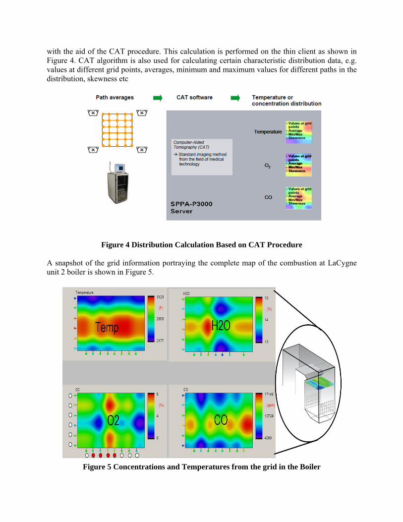
A snapshot of the grid information portraying the complete map of the combustion at LaCygne unit 2 boiler is shown in Figure 5.
Figure 5 Concentrations and Temperatures from the grid in the Boiler

COMBUSTION OPTIMIZER HARDWARE AND SOFTWARE
The functions of the Combustion Optimizer modules ran on a SPPA-T3000 I&C system.
The system comprised of the following components: � Siemens ftServer, e.g. for archiving and optimization � Thin Client with software for CAT display and for Neural networks (PM/SQP) � Standard interface to existing DCS
The Siemens ftServer contains general SPPA-T3000 applications such as the web server, central project containers and the archive. Applications can be accessed via the user interfaces using a standard web browser. The Microsoft Windows server operating system installed on the Siemens server offers users the convenience of a Windows-based application environment. The hardware configuration of SPPA-P3000 Optimizer at LaCygne Unit 2 Power Plant’s unit 2 is shown in Figure 6. The Laser Measurement System is connected to the Siemens ftServer through OPC (object linking and embedding for process control) via TCP/IP. There is also a thin client connected to the ftServer. The Siemens ftServer is connected to the Bailey Infi90 DCS via OPC through a Rovisys application server. This permits access to measured data from the existing DCS, such as coal and air flows or CO and NOx in the flue gas, by the combustion optimization process. It also facilitates sending optimization process signals back to the DCS.
Figure 6 Optimizer Hardware Configuration
The Optimizer control functions are implemented on the Siemens Server in standard T3000 control logic format. Function plans can be generated or engineered in configuration mode. Operation mode is for interaction with the Optimizer and observation of trends and displays

including dynamic presentation of actual and historic values. Displays of function plans in operation mode show the actual values of all signal connections between function blocks. SIGNAL TRANSFER BETWEEN SIEMENS OPTIMIZER AND BAILEY INFI90 DCS
The basic block diagram for signal transfer between the Combustion Optimizer and Bailey Infi90 DCS is shown in Figure 7. There is a watchdog signal available for the communication verification between the optimizer and the DCS. The process measurements from the DCS along with the laser measurements data from the boiler are used to calculate the optimized values in SPPA-P3000 Optimizer. These values are provided as the additive biases to the existing setpoints in the DCS which are transferred to the basic underlying controls and to the field. Safety measures are followed in sequence for incoming setpoint biases before they are used in control and boiler processes. The first safety measure is the minimum and maximum limitation setpoint biases from the Optimizer should be within. Next there is a ramp up and ramp down rate for changes of the incoming setpoint biases so the values do not change dramatically. The next safety measure before transferring the setpoint biases from the SPPA-P3000 Optimizer to the DCS is a bumpless transfer switch. The Operator can switch ON/OFF the SPPA-P3000 Optimizer controls smoothly using this switch. If the Optimizer loses connection to the DCS, the control interface design automatically transfers control back to control room operators.
Figure 7 Signal Transfer between Combustion Optimizer and DCS
Operator has to place a specific function in optimization mode to enable the optimizer biases. There are enable switches for the compartment secondary airflow optimizer biases, the secondary air damper north/south optimizer biases and the individual mill optimizer feeder bias.

COMBUSTION OPTIMIZATION CONTROLS CONCEPT Siemens Combustion Optimizer targeted on reducing the emissions under stringent plant operational constraints. The plant engineer has insight into precisely what the optimizer has been acquainted with and how the process is responding. The controls concept involved ways to minimize emissions by applying primary measures based on optimized combustion adjustments. Combustion optimizer technology was designed to give operators a better understanding of the plant’s data and how to prioritize it to reduce emissions. The Combustion Optimizer reduces uncertainties surrounding the actual combustion process allowing operators more power to overcome the considerable variations normally occurring to fuel properties, fuel flow rate imbalances, load range, and air flow disturbances.
o Hybrid Structure of Closed Loop Controls
The combustion optimizer is a hybrid of model based controls with neural network optimization technology. As shown in Figure 8, it provide closed-loop optimization of fuel and air mixing by manipulating fuel and air levels to balance combustion in the furnace. Different models to represent the boiler behavior were built for the combustion optimization based on classical control theories and based on neural networks. A model based on physical equations requires a large number of parameters, some of which are unknown. For these situations it is viable to use a neural network for modeling the boiler behavior in addition to the model based controllers.
Figure 8 Hybrid Structure of Combustion Optimizer

Figure 9 Combustion Optimizer Controls Overview
The Figure 9 shows an overview of the SPPA-P3000 Combustion Optimization controls. The main controls for emission reduction are
CO distribution balancing o using secondary air north/south damper trim o using compartment airflow setpoint
Staged Combustion
o Fuel staging using Feeder bias o Air staging using compartment airflow setpoint
O2 Reduction
Neural network optimization
The Optimizer is impacted by certain constraints. If the constraints are not met then the optimizer biases are either ramped up/down to zero or are maintained at the same value (frozen) till the constraints are valid. These constraints are also portrayed in Figure 9.

CO distribution balancing using Secondary Air Biases: The objective behind the CO balancing is to uniformly spread the CO distribution in the boiler. Distributing the air properly is a critical step in combustion optimization. The CO distribution in the boiler, determined from the laser measurements through CAT algorithm, was used as control inputs for balancing. Two models were developed one each for the front side and rear side of the boiler. Each of these models has the weighted average of CO measurements calculated for north and south across the boiler. These weighted average act as the control deviation for the PI controllers. As shown in Figure 10, a vertical distribution model was developed for every level in the front and rear of the boiler which determined the amount of secondary air bias for the corresponding level proportional to the distribution of secondary air north/south position setpoint for level A through level G in the boiler.
Figure 10 CO Distribution Balancing using Secondary Air North/South Damper Trim

CO distribution balancing using Compartment Air Setpoint Biases: The CO distribution balancing using the compartment air setpoint biases was performed by balancing the compartment air between the front and rear sections of the boiler. The CO distributions in the boiler, determined from the laser measurements through CAT algorithm, were used as control inputs. A model was built based on weighted average for CO measurements for the front and rear sections of the boiler. This model, as shown in Figure 11, determined the compartment air setpoint bias proportional to the distribution of secondary air flow setpoint for level A through level G.
Figure 11 CO Distribution Balancing using compartment Airflow Setpoint Bias

Staged Combustion
In wall-fired unit, the countermeasures involved in lowering NOx include air staging and fuel staging. At LaCygne Unit 2, as shown in Figure 12, staged combustion technique for NOx control involved adding a portion of the secondary air (staged air) from the main combustion zone to the top levels and reducing the amount of secondary air at the bottom levels. The compartment air adjustments are made to move air to air-starved regions in the furnace and to improve air and fuel mixing within regions. In addition to this, the fuel staging is performed by adding supplementary fuel on the bottom levels and reducing the same amount of fuel on top level of the boiler which sums up the total feeder bias to zero. This methodology reduces stoichiometry during combustion and thus minimizes formation of both fuel and thermal NOx. Hence the staged combustion helps in better completion of the combustion process in the boiler.
Figure 12 LaCygne Unit 2 Staged Combustion
The Feeder Optimizer biases constraints were based on a maximum allowable stack CO, maximum allowable mill dP, maximum allowable mill Amps and minimum mill outlet temperature. The block diagram for the feeder bias controls is shown in Figure 13.

DCSLevel A
Comp. Master
Bias
Level A
Comp. Master
Bias
MAXMIN
MAXMIN RAMPRAMP
BUMP-SWITCH LESS
BUMP-SWITCH LESS
CONSTCONST
Min, Max Ramp Rate
CONSTCONST
Min DmprPos
CONSTCONST DCS
CompartmentMaster OptimizerBiases
.
.
.
.
Level B
Comp. Master
Bias
Level B
Comp. Master
Bias
Level C
Comp. Master
Bias
Level C
Comp. Master
Bias
Level D
Comp. Master
Bias
Level D
Comp. Master
Bias
Level E
Comp. Master
Bias
Level E
Comp. Master
Bias
Level F
Comp. Master
Bias
Level F
Comp. Master
Bias
Level G
Comp. Master
Bias
Level G
Comp. Master
Bias
DCS
MAXMIN
MAXMIN RAMPRAMP
BUMP-SWITCH LESS
BUMP-SWITCH LESS
Switch ON
Logic
Switch ON
Logic
WatchdogWatchdogDCS Watchdog
RampRate
ON
Mill in Auto
Comp MasterOpt Bias ON
AND
&
AND
& 0
Ramp Rate
SWITCHSWITCH
CONSTCONST
RampRate
Econ Avg Temp
I
Tn, kp-up, kp-down
Pulv A Motor Amps
II
II
II
II
MaxMax
MinMin
MaxMaxMax. Allowable Amps
CONSTCONST
Max. Allowable dPCONSTCONST
Pulv A Mill dP
Min. Mill TempCONSTCONST
Pulv A Outlet Temp
Stack CO MaxMax
Max. Allowable CO
CONSTCONST
LLCONSTCONST
Pulv C Motor Amps
MaxMax
MinMin
MaxMaxMax. Allowable Amps
CONSTCONST
Max. Allowable dPCONSTCONST
Pulv C Mill dP
Min. Mill TempCONSTCONST
Pulv C Outlet Temp
Pulv E Motor Amps
MaxMax
MinMin
MaxMaxMax. Allowable Amps
CONSTCONST
Max. Allowable dPCONSTCONST
Pulv E Mill dP
Min. Mill TempCONSTCONST
Pulv E Outlet Temp
Pulv F Motor Amps
MaxMax
MinMin
MaxMaxMax. Allowable Amps
CONSTCONST
Max. Allowable dPCONSTCONST
Pulv F Mill dP
Min. Mill TempCONSTCONST
Pulv F Outlet Temp
Pulv G Motor Amps
MaxMax
MinMin
MaxMaxMax. Allowable Amps
CONSTCONST
Max. Allowable dPCONSTCONST
Pulv G Mill dP
Min. Mill TempCONSTCONST
Pulv G Outlet Temp
MinMaxSP
UL
MinMaxSP
UL
LLCONSTCONST
MinMax
MinMax
MinMax
MinMax
MinMax
SP
SP
SP
SP
SP
UL
UL
UL
Unit Load LoadRange OK
Tra
ck t
o 0
Figure 13 Block Diagram for the Fuel Staging Logic

o Excess O2 Reduction The minimization of excess air is, in fact, one of the most direct and effective primary measures (combustion regulation adjustments) for optimizing performance and NOx emissions in any type of boiler. However, boiler operators are extremely reluctant to use this type of adjustment, due to the possible creation of sub-stoichiometric areas in the furnace which may cause high levels of unburnt fuel or even a plant shutdown. Therefore, relatively high base levels of excess air are habitually used, in spite of its negative effect on heat rate and on the generation of NOx, with priority being given to considerations of operational safety. However, this “critical” parameter is usually calculated as the average of measurements taken at only 4 to 8 points in the boiler outlet, whose representativeness, with regard to the combustion conditions near each burner, is very limited. With the knowledge of the real-time O2 laser measurement values in the boiler, the Combustion Optimizer has better control intelligence for providing the O2 setpoint bias. The CO distribution balancing and the staged combustion controls helped to allow the reduction of the O2 excess for reducing the emissions. This additional logic using CO concentration was implemented to determine the O2 setpoint correction dependant on the actual combustion situation in the boiler. The CO values in the boiler from the laser measurements and the stack CO from the DCS were used to determine the rated CO concentration. The CO setpoint to the integral control was determined as a function of the unit load from the DCS. The optimization controller also has the lower limit for O2 reduction. The Constraints related to O2 SP Optimizer Bias were based on the maximum allowable stack CO. As shown in Figure 14, during the NOx/CO calibration phase and during load ramps, the O2 SP bias is maintained at the same value (frozen).
Figure 14 Block Diagram for O2 Setpoint Reduction Logic

Neural Network Model Overview Neural network technology can be viewed as a multivariate nonlinear nonparametric estimation tool. It shares a descriptive term from biology in that they are represented as networks of simple neuron-like processors. This highly adaptive technology uses a unique combination of neural network and chaotic systems algorithms to learn the complex interactions of process variables from historical data.
The manipulated variables for the neural model used at LaCygne Unit 2 were secondary air north/south damper positions, compartment airflow setpoint and feeder speeds. Some of the input variables comprise of laser measurement readings of temperature, O2 and CO profiles, unspecified basic conditions, such as load. The output variables include the stack CO measurement. The target value to be optimized was the Stack NOx. The neural boiler model was trained, as shown in Figure 15, during the commissioning phase based on real process data for these variables. Sensitivity analysis were performed based on this model so as to find out which manipulated variables have the greatest impact on output or target values. At the end of this sensitivity analysis, a neural boiler model is produced simulating essential impacts of controlled variables on target values.
Figure 15 Neural Network Training
The model created during the commissioning phase replicates the behavior of the boiler in this phase. Slagging and mill wear sometimes have a significant effect on boiler behavior, however. These gradual changes are detected by means of online adaptation of the boiler model, as represented in Figure 16. For this purpose the calculated output and target values of the model are compared with real process data. With the help of the neural network, the optimum manipulated variables for the specified target of NOx reduction are determined with due consideration of constraints. The constraints were related to maximum allowable stack CO and Opacity. The other modeling constraints were to keep the total air and the sum of feeder speeds constant.

An interior-point method with a track record of fast convergence for large-scale optimization problems with constraints was used to solve this optimization problem. The optimization method varies the input variables of the neural network until the target values have been minimized. This iteration produces optimum setpoints for manipulated variables, such as the different secondary air flows. The iteration process is portrayed in Figure 17.
Figure 16 Neural Network Online Adaptation
Figure 17 Neural Network Iterative Optimization
An example of neural network training during the situations when there are no load ramps and iterative optimization of stack NOx is shown in Figure 18. The red trend represents the actual NOx values and blue trend represents the neural network predicted values.

Figure 18 Neural Network Training & Prediction
BOILER OPERATION IMPROVEMENTS WITH COMBUSTION OPTIMIZER
Figure 19 and Figure 20 illustrates snapshots of the long term emission trends with and without the Combustion Optimizer in operation on two different days. The magenta color trend represents the unit load, the black color trend corresponds to excess oxygen and CO is shown in blue color trend. The NOx is shown as red color trend with the flooded green characterizing Combustion Optimizer ON/OFF.
As can be seen in Figure 19 and Figure 20, more than 20% reduction in NOx was achieved when the optimizer was switched ON.
Figure 19 NOx Improvement Trend
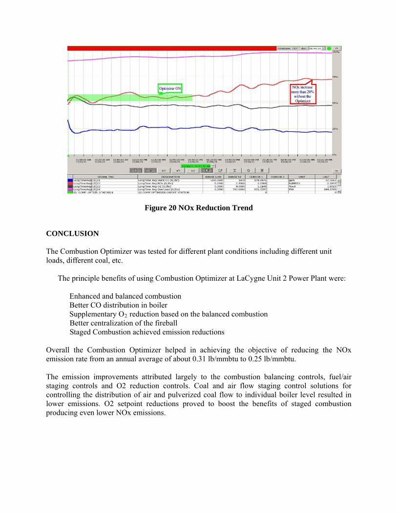
Figure 20 NOx Reduction Trend
CONCLUSION
The Combustion Optimizer was tested for different plant conditions including different unit loads, different coal, etc.
The principle benefits of using Combustion Optimizer at LaCygne Unit 2 Power Plant were: � Enhanced and balanced combustion � Better CO distribution in boiler � Supplementary O2 reduction based on the balanced combustion � Better centralization of the fireball � Staged Combustion achieved emission reductions
Overall the Combustion Optimizer helped in achieving the objective of reducing the NOx emission rate from an annual average of about 0.31 lb/mmbtu to 0.25 lb/mmbtu. The emission improvements attributed largely to the combustion balancing controls, fuel/air staging controls and O2 reduction controls. Coal and air flow staging control solutions for controlling the distribution of air and pulverized coal flow to individual boiler level resulted in lower emissions. O2 setpoint reductions proved to boost the benefits of staged combustion producing even lower NOx emissions.