lower-limb kinematics and kinetics during continuously
TRANSCRIPT
Lower-limb kinematics and kinetics duringcontinuously varying human locomotionEmma Reznick1,†, Kyle R. Embry2,3,4†, Ross Neuman5, Edgar Bolı́var-Nieto1,6, Nicholas P.Fey5, and Robert D. Gregg1,6,*
1University of Michigan, Robotics Institute, Ann Arbor, MI, 48109, USA2University of Texas at Dallas, Department of Mechanical Engineering, Richardson, TX, 75080, USA3Shirley Ryan AbilityLab, Center for Bionic Medicine, Chicago, IL, 60611, USA4Department of Physical Medicine and Rehabilitation, Northwestern University, Chicago, IL, 60611, USA5University of Texas at Austin, Department of Mechanical Engineering, Austin, TX, 78712, USA6University of Michigan, Department of Electrical Engineering and Computer Science, Ann Arbor, MI, 48109, USA*corresponding author: Robert D. Gregg ([email protected])†these authors contributed equally to this work
ABSTRACT
Human locomotion involves continuously variable activities including walking, running, and stair climbing over a range of speedsand inclinations as well as sit-stand, walk-run, and walk-stairs transitions. Understanding the kinematics and kinetics of thelower limbs during continuously varying locomotion is fundamental to developing robotic prostheses and exoskeletons thatassist in community ambulation. However, available datasets on human locomotion neglect transitions between activities and/orcontinuous variations in speed and inclination during these activities. This data paper reports a new dataset that includes thelower-limb kinematics and kinetics of ten able-bodied participants walking at multiple inclines (± 0°, 5° and 10°) and speeds(0.8 m/s, 1 m/s and 1.2 m/s), running at multiple speeds (1.8 m/s, 2 m/s, 2.2 m/s and 2.4 m/s), walking and running with constantacceleration (± 0.2 m/s2 and 0.5 m/s2), and stair ascent/descent with multiple stair inclines (20°, 25°, 30° and 35°). This datasetalso includes sit-stand transitions, walk-run transitions, and walk-stairs transitions. Data were recorded by a Vicon motioncapture system and, for applicable tasks, a Bertec instrumented treadmill.
Background & Summary
To address limitations in amputee locomotion1, robotic prosthetic legs are being developed with specifications for designand control based on able-bodied human biomechanics data2–5. Although wearable robotic devices can have different goals(e.g., reducing energetic cost6, 7), able-bodied data are often used as reference trajectories in the control system8–12 to restorenormative biomechanics in impaired individuals, such as amputees, who otherwise could not walk normally. Most studiesof able-bodied human locomotion report lower-limb kinematics and kinetics during a limited set of steady-state tasks, e.g.,walking13, 14, running15, or stair ascent and descent16, with only a few discrete samples of speed and/or incline for each task14.State-of-art control systems for robotic prosthetic legs are similarly limited to a small set of steady-state locomotion tasks,using finite state machines to control instantaneous transitions between them (risking classification errors and jerky motion attransition points17). However, real-life human locomotion is far from steady state, involving intermittent bouts of walking,stopping, sitting, standing, and stair climbing18. In fact, 75 % of all walking bouts are less than 40 steps in a row19. Non-steadyconditions including transitions between locomotion modes and continuous variations of slopes and speeds are critical tomodeling human locomotion and designing agile robotic prostheses.
Although the biomechanics of able-bodied walking13, running15, sit to stand20, and stair climbing16 have been well-documented as independent locomotion tasks, it is difficult to combine datasets due to differences in the measurements,methods, and participants. Brantley et al.21 recorded electroencephalography, lower-limb electromyography (EMG), andfull body kinematics for ten participants walking on level-ground, ramps, and stairs. Embry et al.14 reported lower-bodykinematics, kinetics, and EMG activity for ten able-bodied participants while walking at multiple speeds and slopes. Schreiberand Moissenet22 reported whole body kinematics, kinetics, and lower-body EMG information for level-ground walking atdifferent speeds. Lencioni et al.23 reported whole body kinematics, kinetics, and lower-body EMG information for level-groundwalking and stair ascent/descent. Hu et al.24 recorded lower-limb kinematics and EMG of ten able-bodied participants duringfree transitions between sitting, standing, level-ground walking, ramp walking, and stair climbing. Camargo et al.25 recordedkinematics, kinetics, and EMG for 22 participants during variable-speed treadmill walking, variable-incline overground walking,
arX
iv:2
108.
1230
7v1
[cs
.RO
] 2
7 A
ug 2
021

variable-height stair climbing, and ramp and stair transitions. However, these studies are missing one or more of the following:joint kinetic measurements, global orientation measurements (e.g., pelvic tilt), enrollment of older participants, a primaryactivity of daily living (e.g., sit-to-stand), transitions between tasks, and/or continuous variations of walking speed and incline(including their combinations).
This data paper considers all these features in reporting the lower-limb measurements of ten able-bodied participants duringsit-stand, walk-run, and walk-stairs transitions (Figure 1), walking at multiple inclines with different speeds, walking/runningat constant acceleration and deceleration rates, and running at multiple speeds. The reported kinematics include pelvic tiltand hip, knee, and ankle joint angles, and joint moments are provided for the treadmill tasks. The dataset also includes theglobal position of reflective markers (hereinafter referred to as “markers”) in 3D space and the force plate measurements whenavailable. These measurements were used to build kinematic and kinetic models to calculate joint angles, velocities, andmoments. We also include video recordings to illustrate the experiments for each of the locomotion tasks.
One purpose for the collected dataset is to provide input data for modeling human kinematics over different locomotiontasks. During a steady gait cycle, each joint angle can be assumed to be a periodic signal and thus can be modeled as a Fourierseries depending on time or a global measurement8. The changes in knee and ankle kinematics due to different walking speedsand inclines can be modeled as a weighted sum of multiple continuous basis functions, e.g., Fourier series14. This allows themodel to continuously interpolate walking kinematics over continuously varying speeds and inclines, giving robotic prostheticlegs more adaptability than switching between a limited set of discrete inclines or speeds. Continuous transitions betweensitting, standing, walking, stair climbing, and running can also be modeled for more natural control of non-steady activities.These kinematic models can be trained based on across-participant averages from the presented dataset to generate baselinecontrol strategies for powered prostheses8–10 and exoskeletons11, 12. Because these models continuously connect a range oftasks, they can be efficiently individualized by heavily weighting one participant-specific task (e.g., level-ground walking)amongst across-participant averages for all other tasks26.
MethodsThis section lays out the procedure from obtaining participant consent to acquiring and processing the data for publication.Each section proceeds step-by-step through the procedure and details the tasks within each ambulation mode. The variety ofspeeds and/or inclines within each mode entail the continuous variation of the dataset.
ParticipantsThe study protocol was approved by the Institutional Review Boards at the University of Texas at Dallas and the Universityof Michigan. This dataset was acquired from ten healthy participants (5 female), aged 20-60 years (30.4 ± 14.9), weighing74.6 ± 9.7 kg, and with an average height of 1.73 ± 0.94 m. To be included, the participants were between 19 and 65 yearsold, self-reported the ability to walk over uneven ground with ease, and had no joint problems in the lower extremities orneuromuscular disorders or diseases that would impair their ability to walk.
Instrumentation and Participant PreparationData were acquired in the University of Texas Southwestern Medical Center motion capture laboratory in Dallas, TX, operatedby University of Texas at Dallas. This laboratory is equipped with a motion capture system, instrumented treadmill, and a4-step adjustable stair set in order to record the kinematics and kinetics of a wide range of tasks, detailed below. Synchronousdata acquisition was managed by the Vicon motion capture system.
Participant PreparationAfter obtaining informed consent and briefing participants about all trials that would be performed, participants were equippedwith motion capture markers. Participants were instructed to wear tight-fitting clothing, and cohesive wraps were used whennecessary to ensure clothing stayed tight to the skin, particularly for two participants (AB06 and AB10). Markers were placedat every location necessary for the Vicon Plug-in Gait lower body model, as well as a custom set of additional markers used toimprove the robustness of segment identification. These additional markers provided a source for filling either a rigid body orpattern, depending on the location of the marker, during events where a required marker for Plug-in Gait was not visible forseveral frames. Note that some of the additional markers were placed close together on 3D printed cluster plates held to the legwith cohesive tape, but these redundant markers are left out of the dataset due to possible motion artifacts. Please see Figure 2for the names of all markers and a description of which markers are used for the conventional gait model. The Plug-in Gaitmarkers were almost always placed on skin or tight-fitting clothes (e.g., yoga pants), with the exception of the thigh markers foronly two participants (AB06 and AB10) which were subsequently constrained to the rigid body during post-processing.
2/15

TreadmillAll flat-ground walking and running tests were conducted at variable speeds and inclines on a Bertec instrumented split-belttreadmill (Bertec Corporation, Columbus, OH). This treadmill has embedded force plates under each belt to acquire kineticsindependently for each leg at 1000 Hz (and downsampled to 100 Hz for publication). The treadmill was remotely controlled bya custom MATLAB code to change the speed and acceleration over randomized tasks at one incline, details discussed later.
Motion CaptureA 10-camera Vicon T40 motion capture system (Vicon, Oxford, UK) was used to record the 3D positions of all markers attachedto participants at 100 Hz. We utilized Vicon’s proprietary Dynamic Plug-in Gait Model to calculate joint angles from markerspositions, where angular conventions are defined in the Nexus 2 user guide27. In trials using the treadmill forceplates, Plug-inGait was also used to approximate joint forces, moments, and powers. The Plug-in Gait software calculates inverse dynamicsto derive joint kinetics from force plate kinetics and motion capture kinematics using the conventional gait model. Furtherinformation on the Plug-in Gait kinetic modeling is available in the Nexus 2 user guide27. An open-source implementation ofthe conventional gait model is introduced in Lebourd et. al28, which closely matches Plug-in Gait results. In our dataset, eachjoint has a consistent sign convention for its angles and moments, where ankle dorsiflexion, knee flexion, and hip flexion aredefined in the positive directions.
Stair DetailsA 4-Step Adjustable Stair Set (Staging Dimensions, Inc., New Castle, Delaware) with no handrails was attached to a platformwith variable height legs. The height of the platform was adjusted to change the inclination of the stairs. This allows for stairheights that closely resemble the 2010 ADA accessibility standards of 4-7in. The inclines (20°, 25°, 30° and 35°) correspondwith riser heights of 3.81 in, 4.72 in, 5.75 in and 6.38 in. Due to lack of force plates in the stairs, kinetic data was not recordedfor any stair walking.
Experimental ProcedureThis study captures the kinematics, force plate and joint kinetics of walking and running on a flat surface, kinematics and forceplate kinetics of sit-to-stand, and kinematics of stair ascent and descent. The acquisition of each of these ambulation modesconsists of a continuous range of tasks that a participant may encounter in day-to-day life, including different inclinations andspeeds and task transitions (Figure 1). While the experiment was designed to randomize different tasks to minimize the effectof fatigue, the progression of ambulation modes (described later) remained constant for ease of acquisition.
We performed a statistical analysis before conducting this experiment to ensure reasonable confidence that we enrolledenough participants, recorded enough strides of each task, and that our sample mean kinematics would be reasonably close tothe population mean. Our metric for success was that based on the 80% confidence interval of the standard deviation of previousexperiments, the intra-participant mean trajectory should be within five degrees of the true intra-participant trajectory at allpoints in time, and similarly that the inter-participant mean is within five degrees of the population inter-participant mean14.The number of strides and participants necessary to meet this condition was found by the formula n =
(Zα/2σ/E
)2, where n
is the necessary number of samples, Zα/2 = 1.645 is the α = 0.10 z-score for a two-tailed distribution, σ is the populationstandard deviation of the data, and E is the maximum difference between the population mean and n-sample mean, in our case5 degrees. The population standard deviation σ is unknown, so we replace this value with the upper and lower 80% confidenceinterval of the standard deviation, s, of a previous, similar experiment14 to produce a range of n values (see Table 1). Weselected practical values of n within this range that are consistent with many other human motion capture studies.
Participant Marker Placement and CalibrationAfter obtaining informed consent and preparing the participant’s marker set (Figure 2), the participant was instructed to standstill for a static calibration of the marker set, and then walk for 10-15 seconds on the treadmill at 1.0 m/s while we recordedtheir joint kinematics. Any unexpected irregularities in able-bodied gait were addressed at this point before proceeding. Pleasesee the Technical Validation section for details.
WalkingA MATLAB program was used to remotely control the treadmill through a protocol that randomized the order of walkingspeed tasks as well as two acceleration tasks. Walking trials progressed through a range of nominal walking speeds (0.8 m/s,1.0 m/s and 1.2 m/s) over the course of each capture. In an effort to increase similarity between participant joint angles, thenominal walking speeds were then normalized with respect to the participant’s leg length, using the formula vnorm = vorig/
√gl0,
where g = 9.81 is the gravity constant and l0 is leg length29. Different acceleration and deceleration rates were also tested (±0.1 m/s2, 0.2 m/s2 and 0.5 m/s2), where 0.1 m/s2 was used to transition between different walking speeds, and 0.2 m/s2 and0.5 m/s2 were tested individually by accelerating from rest to 1.2 m/s, holding for 5 seconds, and decelerating back to rest.These procedures were conducted at multiple inclines covering and slightly exceeding the range of ADA-compliant ramps (±
3/15

0°, 5° and 10°), the order of which was also randomized to minimize the effect of fatigue. These walking speeds and inclinesmatch some of our previously released datasets, which may be useful for comparison30–32. Walking kinematics and kineticsover each incline are shown in Figure 3. Each data capture was conducted at a fixed incline with the treadmill incline featureclamped to prevent surface movement while walking. A tone was played to alert the participant before any changes in speed.
RunningRunning trials were collected on the treadmill in a randomized order of speeds over level ground (1.8 m/s, 2.0 m/s, 2.2 m/sand 2.4 m/s), with speeds normalized by leg length consistent with walking trials29. Data was collected for 30 seconds ateach speed, resulting in the inter-participant average kinematics and kinetics in Figure 4. Walk-run transitions were separatelycaptured and remotely controlled by accelerating from rest to 2.2 m/s at different rates (0.2 m/s2 and 0.5 m/s2), holding thatspeed for 10 seconds, and decelerating at the same rate back to rest. It should be noted that AB04 and AB10 opted out ofperforming some running trials.
Sit-to-StandSit-to-stand transitions were collected by instructing the participant to sit on a backless stool placed on one of the belts of thetreadmill while their feet rested on the other belt. Force plates beneath each belt recorded the ground reaction forces throughthe stool and the participant’s feet throughout the transition, allowing researchers to study the weight transition to and from thefeet throughout the sit-to-stand and stand-to-sit transitions. Six trials were recorded of the participant rising from the chair,standing at rest for a moment, and then sitting. Participants were instructed not to use their hands to assist their transitions. Theinter-participant average kinematics can be seen in Figure 5.
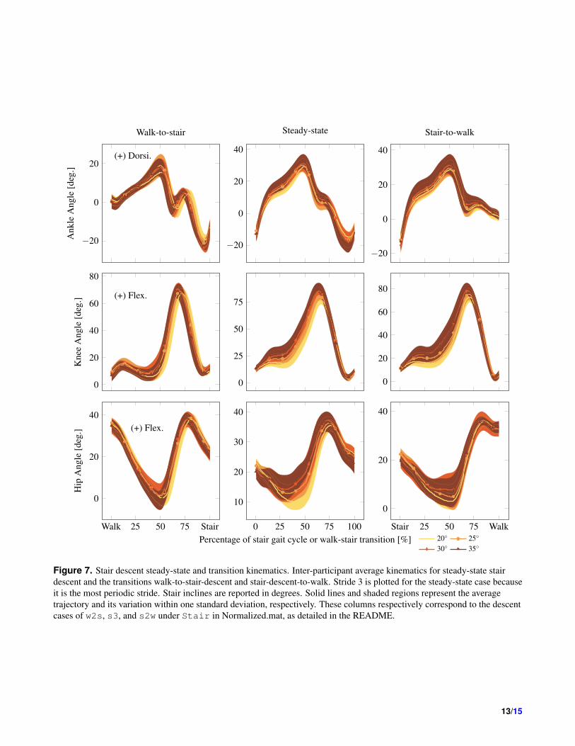
StairsStair trials were conducted over four inclinations of stairs (20°, 25°, 30° and 35°). The participant began 6 ft from the base ofthe staircase, approached the stairs at a self-selected walking speed, ascended the stairs, and walked to the end of the platform.At this point, the capture was ended and the participant was instructed to turn around. This procedure recorded one walk-to-stairand stair-to-walk transition per capture. The participant then began the descent trial from rest at the end of the platform,descended to the bottom of the stairs, and continued to the demarcated starting line. At least five ascent and descent trialswere conducted at each incline, with additional trials being added at the recorder’s discretion. The inter-participant averagekinematics of steady-state and transitional strides are shown for stair ascent in Figure 6 and stair descent in Figure 7.
Motion Capture Post-ProcessingPost processing in Vicon Nexus consisted of rigid body fills, filtering, and a Plug-in Gait model that uses the conventionalgait model and inverse dynamics to calculate joint moments. After labeling the markers to match the marker set in Figure 2, arigid body or pattern fill addressed small gaps for each leg segment (Lthigh, Lshank, Rthigh, Rshank). Gaps in the data were causedby visual occlusion of the markers. The marker trajectories were then filtered with a 4th-order Butterworth Low-Pass filterwith a 6Hz cutoff33 and a Woltring filter with a smoothing parameter of 20 . Finally, the Plug-in Gait model calculated jointkinematics and kinetics (when force plate data was available), and the data was checked for anomalous motion. If anomalieswere found, the motion was corrected at the marker level and the model was run again without filters to prevent over-filtering.
Data ProcessingA custom MATLAB pipeline was implemented to scan through all kinematic trajectories for a given participant, parse trialsinto tasks, parse tasks into strides, time-normalize strides, and compile into a unified MATLAB structure. For walking trials,the treadmill controller was programmed to output a command log after each trial detailing the sequence and timing of thevarious commands, which provided the necessary information to separate a trial into its constituent tasks. A stride was definedas heel strike to subsequent heel strike for a given leg. For all tasks performed on the treadmill, heel strikes were detectedusing forceplate measurements using software provided by Vicon34. For stair trials, heel strikes were manually labeled inVicon Nexus. Heel strikes also determined the periods for stance and swing phases, which are given in the events structof the dataset. Each stride was considered a repeated measure of the given task. For sit-to-stand trials, tasks were separatedalgorithmically by tracking the progression of sagittal plane knee angles, see Figure 5. After heel strike detection, strides werelinearly interpolated to 150 data points. Since all participants in this dataset were able-bodied and assumed to present symmetrickinematics, all joint kinematic fields include data from both the right and left legs without specific side labelling. Once thestrides of a given task were compiled, unsatisfactory examples were removed based on several criteria: strides containing truezeros (i.e., gaps existed in data); strides with outliers in the maximum value of the first derivative (i.e., large discontinuities);steady-state stair strides with large differences between starting and end points (i.e., non-periodicity); and strides whose meanvalues were outliers (offset errors). Outliers were defined as values more than 3 scaled median absolute deviations from themedian. Additional removal of fragmented strides (containing a task change) ensured veracity of the data. This strict judgment
4/15

rejected 8.3% of treadmill strides (Walk, Run, Walk-to-Run) and 7.2% of Stair strides across all participants, leaving a medianof 2006 strides for each participant across all modes and tasks. No sit-to-stand trials were rejected.
Data Records
This 10-person able-bodied dataset can be accessed from the Figshare data repository35 in the form of two MATLAB structures:Streaming.mat is the continuous data from each trial (Table 2) and Normalized.mat contains the same data parsed and normalizedby stride (Table 3). Further documentation for the dataset can be found in the corresponding README file.
Technical ValidationThe manufacturer’s standard procedure for capture volume calibration was performed before each session of experiments,and was repeated as needed if a camera was disturbed for any reason. This procedure entailed calibrating the cameras withinthe capture volume, leveling the treadmill, and setting the volume origin. Similarly, the force plates in the Bertec treadmillwere both hardware zeroed, and software zeroed through the Nexus motion capture system. This zeroing procedure wasrepeated each time the treadmill inclination changed, to account for the loading conditions at the new incline. Finally, a customprocedure was implemented to calibrate the placement of motion capture markers attached to participants. First, all markerswere placed against the bony landmarks described by the Plug-in Gait marker procedure. Then, participants were asked to walkon the treadmill at zero degree incline for at least ten strides and recorded by motion capture. This recording was manuallychecked for good symmetry between left and right side joints and that the range of motion of each joint was similar to what wasexpected for able-bodied participants. If it was determined that the recorded symmetry or range of motion was unnatural for theparticipant, one or more markers would be moved slightly, always less than one centimeter, and the procedure was repeated.This procedure was repeated until joint symmetry and range of motion were deemed within expected ranges by two researchersto prevent bias. Note that this procedure would need to be modified for patient populations with different expected range ofmotion or gait asymmetry.
Usage NotesOur dataset includes a MATLAB script entitled exampleUseScript.m, which gives an example of how to quickly accessdifferent types of data within the MATLAB structure. In this example script, we have plotted the sagittal-plane thigh kinematicsand force plate vertical load for AB04 walking for one minute at 1.0 m/s at −10° slope. All 59 strides performed by thisparticipant are superimposed in this plot. Please see exampleUseScript.m for full explanation on how to access this data.
Code AvailabilityThe dataset and the code to post-process the data and control the Bertec treadmill can be accessed though MATLAB and isdocumented with a README file describing the data hierarchy. The MATLAB code that remotely controls the Bertec treadmillrunning a designed protocol is available with the dataset. This code is documented with its own README file.
References1. Hood, S., Ishmael, M. K., Gunnell, A., Foreman, K. B. & Lenzi, T. A kinematic and kinetic dataset of 18 above-knee
amputees walking at various speeds. Sci. Data 7, 150, https://doi.org/10.1038/s41597-020-0494-7 (2020).
2. Azocar, A. F., Mooney, L. M., Hargrove, L. J. & Rouse, E. J. Design and characterization of an open-source robotic legprosthesis. In 2018 7th IEEE Int. Conf. Biomed. Robot. Biomechatronics, 111–118, https://doi.org/10.1109/BIOROB.2018.8488057 (2018).
3. Elery, T., Rezazadeh, S., Nesler, C. & Gregg, R. D. Design and validation of a powered knee-ankle prosthesis withhigh-torque, low-impedance actuators. IEEE Trans. Robot. 36, 1649–1668, https://doi.org/10.1109/TRO.2020.3005533(2020).
4. Lenzi, T. et al. Design, development, and testing of a lightweight hybrid robotic knee prosthesis. Int. J. Rob. Res. 37,953–976 (2018).
5. Lawson, B. E. et al. A robotic leg prosthesis: Design, control, and implementation. IEEE Robot. Autom. Mag. 21, 70–81,https://doi.org/10.1109/MRA.2014.2360303 (2014).
6. Zhang, J. et al. Human-in-the-loop optimization of exoskeleton assistance during walking. Science 356, 1280–1284 (2017).
5/15
7. Lee, S. et al. Autonomous multi-joint soft exosuit with augmentation-power-based control parameter tuning reduces energycost of loaded walking. J. neuroengineering rehabilitation 15, 1–9 (2018).
8. Quintero, D., Villarreal, D. J., Lambert, D. J., Kapp, S. & Gregg, R. D. Continuous-phase control of a poweredknee–ankle prosthesis: Amputee experiments across speeds and inclines. IEEE Trans. Robot. 34, 686–701, https://doi.org/10.1109/TRO.2018.2794536 (2018).
9. Embry, K. R. & Gregg, R. D. Analysis of continuously varying kinematics for prosthetic leg control applications. IEEETrans. Neural Syst. Rehabil. Eng. 29, 262–272, https://doi.org/10.1109/TNSRE.2020.3045003 (2020).
10. Best, T. K., Embry, K., Rouse, E. J. & Gregg, R. D. Phase-variable control of a powered knee-ankle prosthesis overcontinuously varying speeds and inclines. In IEEE/RSJ International Conference on Intelligent Robots and Systems (2021).
11. Kang, I., Hsu, H. & Young, A. The effect of hip assistance levels on human energetic cost using robotic hip exoskeletons.IEEE Robotics Autom. Lett. 4, 430–437 (2019).
12. Wang, J. et al. Comfort-centered design of a lightweight and backdrivable knee exoskeleton. IEEE Robotics Autom. Lett. 3,4265–4272 (2018).
13. Winter, D. A. Biomechanical motor patterns in normal walking. J. Mot. Behav. 15, 302–330, https://doi.org/10.1080/00222895.1983.10735302 (1983).
14. Embry, K. R., Villarreal, D. J., Macaluso, R. L. & Gregg, R. D. Modeling the kinematics of human locomotion overcontinuously varying speeds and inclines. IEEE Trans. Neural Syst. Rehabil. Eng. 26, 2342–2350, https://doi.org/10.1109/TNSRE.2018.2879570 (2018).
15. Novacheck, T. F. The biomechanics of running. Gait Posture 7, 77–95, https://doi.org/10.1016/S0966-6362(97)00038-6(1998). arXiv:1011.1669v3.
16. Riener, R., Rabuffetti, M. & Frigo, C. Stair ascent and descent at different inclinations. Gait Posture 15, 32–44,https://doi.org/10.1016/S0966-6362(01)00162-X (2002).
17. Tucker, M. R. et al. Control strategies for active lower extremity prosthetics and orthotics: a review. J. neuroengineeringrehabilitation 12, 1–30 (2015).
18. Orendurff, M. S., Bernatz, G. C., Schoen, J. A. & Klute, G. K. Kinetic mechanisms to alter walking speed. Gait Posture27, 603–610, https://doi.org/10.1016/j.gaitpost.2007.08.004 (2008).
19. Orendurff, M. S. How humans walk: Bout duration, steps per bout, and rest duration. J. Rehabil. Res. Dev. 45, 1077–1090,https://doi.org/10.1682/JRRD.2007.11.0197 (2008).
20. Nuzik, S., Lamb, R., VanSant, a. & Hirt, S. Sit-to-stand movement pattern: A kinematic study. Phys. Ther. 66, 1708–1713(1986).
21. Brantley, J. A., Luu, T. P., Nakagome, S., Zhu, F. & Contreras-Vidal, J. L. Data descriptor: Full body mobile brain-body imaging data during unconstrained locomotion on stairs, ramps, and level ground. Sci. Data 5, 1–10, https://doi.org/10.1038/sdata.2018.133 (2018).
22. Schreiber, C. & Moissenet, F. A multimodal dataset of human gait at different walking speeds established on injury-freeadult participants. Sci. Data 6, 111, https://doi.org/10.1038/s41597-019-0124-4 (2019).
23. Lencioni, T., Carpinella, I., Rabuffetti, M., Marzegan, A. & Ferrarin, M. Human kinematic, kinetic and EMG data duringdifferent walking and stair ascending and descending tasks. Sci. Data 6, 309, https://doi.org/10.1038/s41597-019-0323-z(2019).
24. Hu, B., Rouse, E. & Hargrove, L. Benchmark datasets for bilateral lower-limb neuromechanical signals from wearablesensors during unassisted locomotion in able-bodied individuals. Front. Robotics AI 5, 14, https://doi.org/10.3389/frobt.2018.00014 (2018).
25. Camargo, J., Ramanathan, A., Flanagan, W. & Young, A. A comprehensive, open-source dataset of lower limb biomechanicsin multiple conditions of stairs, ramps, and level-ground ambulation and transitions. J. Biomech. 119, 110320, https://doi.org/10.1016/j.jbiomech.2021.110320 (2021).
26. Reznick, E., Embry, K. & Gregg, R. D. Predicting individualized joint kinematics over a continuous range of slopes andspeeds. In IEEE RAS/EMBS Int. Conf. Biomed. Robot. Biomechatronics, 666–672, https://doi.org/10.1109/BioRob49111.2020.9224413 (2020).
27. Vicon Motion Systems, Inc., Oxford, UK. Nexus 2.11 Documentation: Kinetic Modeling, https://docs.vicon.com/display/Nexus211/Kinetic+modeling (2021).
6/15

28. Leboeuf, F. et al. The conventional gait model, an open-source implementation that reproduces the past but prepares forthe future. Gait Posture 69, 126–129, https://doi.org/10.1016/j.gaitpost.2019.04.015 (2019).
29. Hof, A. L. Scaling gait data to body size. Gait Posture https://doi.org/10.1016/0966-6362(95)01057-2 (1996).
30. Embry, K., Villarreal, D., Macaluso, R. & Gregg, R. The effect of walking incline and speed on human leg kinematics,kinetics, and EMG, https://doi.org/10.21227/gk32-e868 (2018).
31. Macaluso, R., Embry, K., Villarreal, D. & Gregg, R. Human leg kinematics, kinetics, and EMG during phase-shiftingperturbations at varying inclines, https://doi.org/10.21227/12hp-e249 (2020).
32. Elery, T., Rezazadeh, S., Reznick, E., Gray, L. & Gregg, R. D. Effects of a powered knee-ankle prosthesis on amputee hipcompensations: A case series, https://doi.org/10.21227/sngq-4x29 (2020).
33. Winter, D. A. Biomechanics and motor control of human movement (John Wiley & Sons, 2009).
34. Vicon Motion Systems, Inc., Oxford, UK. Bertec Treadmill Gait Cycle Events, https://www.vicon.com/software/models-and-scripts/bertec-treadmill-gait-cycle-events/ (2021).
35. Reznick, E. et al. Lower-limb kinematics and kinetics during continuously varying human locomotion. figshare https://doi.org/XXXX (2020).
36. Vicon Motion Systems, Inc., Oxford, UK. Nexus 2.11 Documentation: Lower Body Modeling with Plug-in Gait,https://docs.vicon.com/display/Nexus211/Lower+body+modeling+with+Plug-in+Gait (2021).
AcknowledgementsThis work was supported by the National Institute of Child Health & Human Development of the NIH under Award NumberR01HD094772. The content is solely the responsibility of the authors and does not necessarily represent the official views ofthe NIH. Robert D. Gregg, IV, Ph.D., holds a Career Award at the Scientific Interface from the Burroughs Wellcome Fund.
The authors would like to thank Lizbeth Zamora for her help with data acquisition and data post-processing, RebeccaMacaluso for her help adapting the treadmill remote control, and Shihao Cheng, Vamsi Peddinti, Erica Santos, and Kevin Bestfor their help debugging the dataset.
Author contributionsEmma Reznick planned and performed the experiment, post-processed and debugged the data, and is a co-first author of thispaper.
Kyle R. Embry planned and performed the experiment, post-processed and debugged the data, and is a co-first author of thispaper.
Ross Neuman planned and performed the experiment, wrote the code for task separation and stride normalization, andcontributed to the paper.
Edgar Bolívar assisted with participant recruitment, debugging of the dataset, and contributed significantly to writing andediting the paper.
Nicholas Fey contributed to experimental planning as well as co-supervision of data acquisition, processing and interpretation.Dr. Fey was a senior personnel of the grant funding this work.
Robert D. Gregg managed the study design and execution, data processing/debugging, and contributed to paper writing andediting. Dr. Gregg was the PI of the grant funding this work.
Competing interestsThe authors declare no competing interests.
Figures & Tables
7/15

StairsSit
Walk Run
T1 T2
T3
Figure 1. Locomotion modes and practical transitions (T1 through T3) considered in this study. ‘Walk’ and ‘Run’ occur on aflat surface, whereas ‘Stairs’ occurs on a staircase. All modes except ‘Sit’ are continuously parameterized by speed andinclination, which are sampled in the dataset. Note a sit-stand transition corresponds to T1 with zero gait speed in ‘Walk.’
Reflective Marker
1
2
4
5
67
8
9 10
11 12
13
1
4
5
67
89
10
3
# Anatomical Description Code
1 Iliac Spine LIC
2 *Anterior Superior Iliac Spine LASI*
3 LPSI*
4
*Posterior Superior Iliac Spine
Greater Trochanter LGT
5 *Thigh LTHI*
6 Medial Knee LKNEM
7 *Knee LKNE*
8 *Tibia LTIB*
9 Medial Ankle LANKM
10 *Ankle LANK*
11 First Metatarsal L1M
12 *Toe LTOE*
13 Fifth Metatarsal L5M
14 *Heel LHEE*
* Used to Derive Kinematics
14
1
2
3
5
7
8
1014
13
12
Subject Markers
Figure 2. Marker Set: Markers were placed on left and right limbs symmetrically, left side markers shown. Markers notedwith a ‘*’ are used in the conventional gait model. For full description of marker locations, see Nexus 2 user guide36.
Lower s Upper s Lower n Upper n Selected nintra-participant 6.95 8.22 2.28 4.36 5inter-participant 7.34 15.83 3.480 16.17 10
Table 1. Sample Size Calculations
8/15

−20
0
20 (+) Dorsi.
Ang
le[d
eg.]
Ankle
0
20
40
60
80
(+) Flex.
Knee
0
20
40
60 (+) Flex.
Hip
−1.5
−1
−0.5
0(+) Dorsi.
Mom
ent[
N·m
/kg]
−0.5
0
0.5(+) Flex.
−1
−0.5
0
0.5
1(+) Flex.
0 25 50 75 100
0
2
Pow
er[W
/kg]
-(+)
Gen
.
0 25 50 75 100
−2
−1
0
1
Percentage of gait cycle [%]0 25 50 75 100
0
1
2
10◦ 5◦ 0◦
−5◦ −10◦
Figure 3. Inter-participant average walking kinematics and kinetics for all inclines at 1.0 m/s. Inclines reported in degrees.Foot contact corresponds to 0 % of the gait cycle. Solid lines and shaded regions represent the average trajectory and itsvariation within one standard deviation, respectively. Positive or negative normalized power denotes generation (Gen.) orabsorption (Abs.) of mechanical power, respectively. These plots correspond to Walk in Normalized.mat, as detailed in theREADME.
9/15

−20
0
20(+) Dorsi.
Ang
le[d
eg.]
Ankle
0
20
40
60
80(+) Flex.
Knee
0
20
40 (+) Flex.
Hip
−3
−2
−1
0(+) Dorsi.
Mom
ent[
N·m
/kg]
−1
0
1
(+) Flex.
−1
0
1(+) Flex.
0 25 50 75 100
−5
0
5
10
Pow
er[W
/kg]
-(+)
Gen
.
0 25 50 75 100
−4
−2
0
2
Percentage of gait cycle [%]0 25 50 75 100
0
2
1.8 m/s 2.0 m/s2.2 m/s 2.4 m/s
Figure 4. Inter-participant average running kinematics and kinetics at all speeds. Foot contact corresponds to 0 % of the gaitcycle. Solid lines and shaded regions represent the average trajectory and its variation within one standard deviation,respectively. Positive or negative normalized power denotes generation (Gen.) or absorption (Abs.) of mechanical power,respectively. These plots correspond to Run in Normalized.mat, as detailed in the README.
10/15

0
10
20
30
(+) Dorsi.
Ank
leA
ngle
[deg
.]Sit-to-stand
0
10
20
30
Stand-to-sit
0
50
100
(+) Flex.
Kne
eA
ngle
[deg
.]
0
25
50
75
Sit 25 50 75 Stand0
20
40
60
80
100
(+) Flex.
Percentage of sit-to-stand [%]
Hip
Ang
le[d
eg.]
Stand 25 50 75 Sit
20
40
60
80
100
Percentage of stand-to-sit [%]
Figure 5. Inter-participant average sit-to-stand kinematics. Solid lines and shaded regions represent the average trajectory andits variation within one standard deviation, respectively. These plots correspond to SitStand in Normalized.mat, as detailedin the README.
11/15

−10
0
10
20(+) Dorsi.
Ank
leA
ngle
[deg
.]
Walk-to-stair
0
20
Steady-state
−20
0
20
Stair-to-walk
0
20
40
60
80
(+) Flex.
Kne
eA
ngle
[deg
.]
0
50
100
0
20
40
60
80
Walk 25 50 75 Stair
0
20
40
60 (+) Flex.
Hip
Ang
le[d
eg.]
0 25 50 75 1000
20
40
60
Percentage of stair gait cycle or walk-stair transition [%]Stair 25 50 75 Walk
0
20
40
60
20◦ 25◦
30◦ 35◦
Figure 6. Stair ascent steady-state and transition kinematics. Inter-participant average kinematics for steady-state stair ascentand the transitions walk-to-stair-ascent and stair-ascent-to-walk. Stride 3 is plotted for the steady-state case because it is themost periodic stride. Stair inclines are reported in degrees. Solid lines and shaded regions represent the average trajectory andits variation within one standard deviation, respectively. These columns respectively correspond to the ascent cases of w2s, s3,and s2w under Stair in Normalized.mat, as detailed in the README.
12/15
−20
0
20(+) Dorsi.
Ank
leA
ngle
[deg
.]
Walk-to-stair
−20
0
20
40
Steady-state
−20
0
20
40
Stair-to-walk
0
20
40
60
80
(+) Flex.
Kne
eA
ngle
[deg
.]
0
25
50
75
0
20
40
60
80
Walk 25 50 75 Stair
0
20
40(+) Flex.
Hip
Ang
le[d
eg.]
0 25 50 75 100
10
20
30
40
Percentage of stair gait cycle or walk-stair transition [%]Stair 25 50 75 Walk
0
20
40
20◦ 25◦
30◦ 35◦
Figure 7. Stair descent steady-state and transition kinematics. Inter-participant average kinematics for steady-state stairdescent and the transitions walk-to-stair-descent and stair-descent-to-walk. Stride 3 is plotted for the steady-state case becauseit is the most periodic stride. Stair inclines are reported in degrees. Solid lines and shaded regions represent the averagetrajectory and its variation within one standard deviation, respectively. These columns respectively correspond to the descentcases of w2s, s3, and s2w under Stair in Normalized.mat, as detailed in the README.
13/15

Table 2. Streaming.mat - data without parsing/normalizing
Field withinstructure Units Sampling
rate Contents
marker (m) 100 Hz
Position in the global coordinate frame of the markersdefined in Figure 2.Array Format: (total frames x 4)First Dimension: Frames in trialSecond Dimension: x/y/z/e location in global space, e iswhether the marker exists
jointAngle (deg) 100 Hz
Pelvic tilt, hip, knee, and ankle angles as defined in theVicon’s Plug-in Gait model28.Array Format: (total frames x 3)First Dimension: Frames in trialSecond Dimension: x/y/z rotation in local space
jointForce (N/kg) 100 Hz
Force vectors acting on the hip, knee, and ankle joints,given in the more distal segment’s frame of reference.Array Format: (total frames x 3)First Dimension: Frames in trialSecond Dimension: x/y/z joint force
jointMoment (N.m/kg) 100 Hz
Pelvic tilt, hip, knee, and ankle moments normalized bythe participant’s mass as defined in the Vicon’s Plug-inGait model28.Array Format: (total frames x 3)First Dimension: Frames in trialSecond Dimension: x/y/z joint moments
jointPower (W/kg) 100 Hz
Estimated power at each joint normalized by the par-ticipant’s mass. It results from the multiplication ofjointMoment and the estimated joint velocity.Array Format: (total frames x 3)First Dimension: Frames in trialSecond Dimension: x/y/z joint power
forceplates
Force: (N)Moment:(N.m)COP: (m)
1000 Hz
Resulting forces and moments in a 3D-frame with originat the center of pressure (COP). The force plates are em-bedded in the two belts of the instrumented treadmill.Array Format: (total frames x 3)First Dimension: Frames in trialSecond Dimension: x/y/z of variable in global space
events
LHS: (frame)RHS: (frame)StrideTime:(frame)VelProf: (m/s)
N/A
Heel Strikes used for normalization (L/R) and the durationof each stride (L/RStrideTime).Array Format: (1 x HS or stride)Velocity Profiles (Walk only: Cvel,Rvel,Lvel): Com-manded treadmill velocity (m/s), L/R stride velocity (m/s)Array Size: (1 x frame)
14/15

Table 3. Normalized.mat - data parsed and normalized by strides/cycles
Field within structure Unit Contents
marker (m)
Array Format: (150 x 4 x stride)First Dimension: normalized sample gait over the stride/task (150pt)Second Dimension: x/y/z/e location/existence in global spaceThird Dimension: stride number
jointAngle (deg)
Array Format: (150 x 3 x stride)First Dimension: normalized sample gait over the stride/task (150pt)Second Dimension: x/y/z rotation in local spaceThird Dimension: stride number (L/R leg have been concatenated)
jointForce (N/kg)
Array Format: (150 x 3 x stride)First Dimension: normalized sampled gait over the stride/task (150pt)Second Dimension: x/y/z joint forceThird Dimension: stride number (L/R leg have been concatenated)
jointMoment (N.m/kg)
Array Format: (150 x 3 x stride)First Dimension: normalized sampled gait over the stride/task (150pt)Second Dimension: x/y/z joint momentThird Dimension: stride number (L/R leg have been concatenated)
jointPower (W/kg)
Array Format: (150 x 3 x stride)First Dimension: normalized sampled gait over the stride/task (150pt)Second Dimension: x/y/z joint powerThird Dimension: stride number (L/R leg have been concatenated)
forceplatesForce: (N)Moment: (N.m)COP: (m)
Array Format: (150 x 3 x stride)First Dimension: normalized sampled gait over the stride/task (150pt)Second Dimension: x/y/z of variable in global spaceThird Dimension: stride number (L/R leg have been concatenated)
eventsHS: (frame)CutPoints: (frame)
Array Format: (stride x 3)First Dimension: stride number (L/R leg have been concatenated)Second Dimension: start/end/duration of stride in frames (100Hz)
15/15