low voltage controls & distribution - siemens answers - siemens
TRANSCRIPT

s
Low Voltage Controls & Distribution
Answers for industry.
SIRIUSDatasheet 2009

2
Pressing, equipping, transporting. These functions run inmany automated production environments. You’ll findeverything that you need to switch, protect and start motorswith the extensive portfolio of the modular SIRIUS system.
Everything. Easy. SIRIUS
For more than 110 years now we have been developing andmanufacturing industrial control products. We have alwaysfollowed the philosophy to make it easier to use-whether inthe electrical cabinet, in the field or directly at the machine.Today we have combined our complete range of industrialcontrols under one star: SIRIUS
An important element of our SIRIUS industrial controls is theextensive range of products that we can offer associated withprotecting, controlling , switching motor loads and systems.From well-proven and reliable contactors through relays thatare easy to use to our innovative SIRIUS SC solid-stateswitching devices for use in the toughest of the conditions.With SIRIUS you always switch simply, safely and reliably. WithSIRIUS industrial controls, you can look to the future withconfidence.

3
1 IntroductionSiemens Automation and Drives. Welcome.Sharpen your competitive edge. Totally IntegratedAutomation. Integrated energy distribution from a singlesource. Totally Integrated Power.Low-Voltage Controls and Distribution - The basis forprogressive solutions.SIRIUS Industrial ControlsLow-Voltage Power Distribution
2 Controls -Contactors and Contactor Assemblies3RT Air break contactors for switching motors3RT and 3TF vacuum contactors for switching motors3RA13, 3RA14, Contactor Assemblies3RT, 3RH, 3TC, 3TK Contactors for Special Applications3RH Contactor Relays and Latched Contactor Relays
2a Controls - (Technical Information)Contactors and Contactor Assemblies3RT Air break contactors for switching motors3RT and 3TF vacuum contactors for switching motors3RA13, 3RA14, Contactor Assemblies3RT, 3RH, 3TC, 3TK Contactors for Special Applications3RH Contactor Relays and Latched Contactor Relays
3 Protection Equipment3RV Motor Protection Circuit Breaker3RB2 Microprocessor based Overload Relays3RU1 Thermal Overload Relays
3a Protection Equipment(Technical Information)3RV Motor Protection Circuit Breaker3RB2 Microprocessor based Overload Relays3RU1 Thermal Overload Relays
4 Soft Starters and Motor Starters3RW Soft Starters3RE Encapsulated Starters
4a Soft Starters and Motor Starters(Technical Information)3RW Soft Starters3RE Encapsulated Starters
5 Monitoring and Control DevicesSIMOCODE 3UF Motor Management and Control Devices3UG Monitoring Relays for Electrical and Additional Measurements3RN1 Thermistor Motor Protection3TK28 Safety Relays
5a Monitoring and Control Devices(Technical Information)SIMOCODE 3UF Motor Management and Control Devices3UG Monitoring Relays for Electrical and Additional Measurements3RN1 Thermistor Motor Protection3TK28 Safety Relays
S I R
I U
S
I n d
u s
t r
i a
l C
o n
t r
o l
s

4
Explanations
General information
Dimensions
All dimensions in mm.
ATEX explosion protection
In many industries the production, processing, transport andstorage of combustible substances are accompanied byescaping gases, vapor or spray which find their way into theenvironment. Other processes result in combustible dust.Together with the oxygen in the air, the result can be anexplosive atmosphere which will explode if ignited.
Serious injury to persons and damage to property can resultparticularly in the chemical and petrochemical industry,mineral oil and natural gas production, mining, mills (e.g.grain, solid materials) and many other sectors.
To guarantee the maximum possible safety in these areas, thelegislators of most countries have drawn up requirements inthe form of laws, regulations and standards. In the course ofglobalization, great progress has been made with regard touniform directives for explosion protection.
With Directive 94/9/EC, the European Union laid thefoundations for complete harmonization by requiring that allnew devices as from 1st July 2003 have to be approved inaccordance with this directive.
In this catalog, special attention is drawn to devices whichcomply with the ATEX Directive. However, it does not replaceintensive study of the relevant fundamentals and directiveswhen planning and installing electrical systems.
Devices approved according to UL standards
UL standards are applied in North America and a number ofother countries. This is important in particular for Europeanexports of electrical switchgear and machine-integratedequipment, above all to the USA. Acceptance and delivery arepossible only if the relevant UL standards are satisfied.
UL 508A describes the design of control cabinets and the useof builtin components, sometimes with reference to other ULstandards. As such, this standard represents the basis for allelectrical systems used in North America.
Numerous SIRIUS, SENTRON, SIVACON, ALPHA and BETAdevices comply with UL standards and can thus be used world-wide in IEC/EN as well as UL applications within the scope ofthe defined application.
With our products for low-voltage control and low-voltagecircuit protection it is easy to build control cabinets accordingto UL standard.
The range of low-voltage control products according to ULstandard includes our SENTRON circuit breakers and SIRIUScontrols - everything from motor-protective circuit breakers andstarters to contactors, overload relays, and not forgetting ourSIRIUS transformers and filters.
Also in our product range are SENTRON switch disconnectorsand various SIRIUS detecting devices and command devices.
Distribution functions can be performed with our busbarsystems and terminal blocks.
And of course our offering also includes miniature circuitbreakers and fuses.

1Introduction
1/2 Automation and Drives. Welcome
1/4 Sharpen your competitive edge. TotallyIntegrated Automation
1/6 Integrated energy distribution from asingle source. Totally Integrated Power
1/8 Low-Voltage Controls and Distribution.The basis for progressive solutions.
1/10 SIRIUS Industrial Controls.
1/11 Low-Voltage Power Distribution.

1
1/2
Siemens Automation and Drives.Welcome
More than 70,000 people aiming for the same goal:increasing your competitiveness. That’s SiemensAutomation and Drives.
We offer you a comprehensive portfolio for sustainedsuccess in your sector, whether you’re talkingautomation engineering, drives or electricalinstallation systems. Totally Integrated Automation(TIA) and Totally Integrated Power (TIP) form the coreof our offering. TIA and TIP are the basis of ourintegrated range of products and systems for themanufacturing and process industries as well asbuilding automation. This portfolio is rounded off byinnovative services over the entire life cycle of yourplants.
Learn for yourself the potential our products andsystems offer. And discover how you can permanentlyincrease your productivity with us.
Your regional Siemens contact can provide moreinformation. He or she will be glad to help.

1
1/3

1
1/4
Sharpen your competitive edge.Totally Integrated Automation
With Totally Integrated Automation (TIA), Siemens is the onlymanufacturer to offer an integrated range of products andsystems for automation in all sectors - from incoming goods tooutgoing goods, from the field level through the productioncontrol level to connection with the corporate managementlevel.
On the basis of TIA, we implement solutions that are perfectlytailored to your specific requirements and are characterized bya unique level of integration. This integration not only ensuressignificant reductions in interface costs but also guarantees thehighest level of transparency across all levels.
����������� �
��� �������
������������� ���������
��� ����
����������
������������
����������
��� �
�������� � ������� �������
�������������� �����������������
��� �
������������� �������� ���� ��!
"�������"���# �$��������#�%�� �#
� ������������ ������
"� �����#���� ��"�������������#������������"�&� ����
��(%����)������ �(�� ������ ��
���&��&(��������� ��������
����������
� �������� �������
#���
� !$%��&���'�(�� ��
#���

1
1/5
��������������
����
���������
��������'������ �������
��������(���#��� ��������������
����������� ��� ���#��� *��+###*��,+��#
��������-��-������������ ���
��������� ��#
����%���#��� ������� �����(��&(��.������� /������&�& ��� ����� �������������
�������� ��� �+��#��*&��(������ �/�������
�������� �� ����!��"��
�������
� !$%��&���'�(�� ��
������'�
��� �������
It goes without saying that you profit from Totally IntegratedAutomation during the entire life cycle of your plants - from thefirst planning steps, through operation, right up tomodernization. Consistent integration in the furtherdevelopment of our products and systems guarantees a highdegree of investment security here.
Totally Integrated Automation makes a crucial contributiontowards optimizing everything that happens in the plant andthus creates the conditions for a significant increase inproductivity.

1
1/6
Integrated energy distribution from a single source.Totally Integrated Power
Totally Integrated Power (TIP) brings together all thecomponents of electrical energy distribution into an integratedwhole. Thus TIP provides the answer to growing marketdemands in the planning, construction and use of utilitybuildings and industrial buildings.
On the basis of TIP, we offer integrated solutions for energydis-tribution, from medium voltage to the power outlet. TotallyInte-grated Power is based here on integration in planning andconfiguring as well as on perfectly matched products andsystems.
������������!�"#�
%�������'
��))*�+,
����%���-
��� & � !��� �& $���&�
���!$��%�� !�%�%��.%
��..$ &���&�
�����%%/��!$��&� �$��.��&�
0��!.� � ��.� �
#�� ���/(% ��� �%�%
��� & � !��� �& $���&�
���!$��%�� !�%�%��.%
��..$ &���&�
�����%%/��!$��&� �$��.��&�
0��!.� � ��.� �
#�� ���/(% ��� �%�%

1
1/7
Totally Integrated Power offers communicationand software modules for connecting the energydistribution systems to industrial automation andbuilding automation. This enables theimplemen-tation of significant savings potential.
������������ � �����������
������� ����� � ��
����� �� �������������� ��
���� �����
��� ����
��
��
��
��
��
�������
��� ��� �� ��� �� ��� � ��� ��
��� ����
��
��
��
��
��
�������
��� ��� �� ��� �� ��� � ��� ��
��� ����
��
��
��
��
��
�������
��� ��� �� ��� �� ��� � ��� ��
���
��������
���������
�������������������
����������������
����������
��%%� ������.� � ��.� �
�����&1�/������&�
��& ��� � ��
��������% ��"��2$��&��
��%���� ���
�$&�!& �$��.��&� ��+������
��� ��� �+�������������������������0
-����1 �� ���#���������������0��
��� �+�����2 ���������� ����+ �0 ��������
��#��� ���������� �
��%%� ������.� � ��.� �
�����&1�/������&�
��& ��� � ��
��������% ��"��2$��&��
��%���� ���
�$&�!& �$��.��&� ��+������
��� ��� �+�������������������������0
-����1 �� ���#���������������0��
��� �+�����2 ���������� ����+ �0 ��������
��#��� ���������� �

1
1/8
Low-Voltage Controls and Distribution.The basis for progressive solutions.
Extremely high demands are made on modern low-
voltage controls and distribution: users want cost-
effective solutions that are easy to integrate in control
cabinets, distribution boards and distributed systems
and can communicate perfectly with each other.
Siemens has the answer: SIRIUS industrial controls
and low-voltage power distribution with SIVACON,
SENTRON and SIMARIS.
SIRIUS industrial controls
The SIRIUS range has everything you need for switching,
protecting and starting loads. Products for monitoring, control,
detection, commanding, signaling and power supply round off
the spectrum of in-dustrial controls. Combined with Totally
Integrated Automation, Safety Integrated and ECOFAST, our
product portfolio can be bundled to create optimized systems.
All in all, Siemensprovides innovative controls with modern
features, such as integrated communication and safety
technology that work to your advantage:
The basis for ground-breaking integrated solutions.
SIRIUS Safety Integrated
product range
SIRIUS modular system

1
1/9
Low-voltage power distribution with
SIVACON, SENTRON and SIMARIS
Non-residental buildings and industrial plants have one thing in
common: without electricity, everything comes to a halt. The
availability, safety and cost effectiveness of the power
distribution system is of utmost importance – from the
medium voltage supply point through to the socket outlet. And
only integrated solutions can ensure maximum efficiency for
planning, configuration and operation.
The concept is called Totally Integrated Power from Siemens.
Total integration in planning and configuration creates
synergies and saves costs. Perfectly matched products and
systems provide efficient engineering and reliable operation. In
the field of low-voltage power distribution, the following
product ranges are available:
SIVACON: From flexible busbar trunking systems through to
safe power distribution boards and motor control centers.
SENTRON: From well-proven switch disconnectors through to
intelligent circuit breakers.
Software for power distribution: Everything for
dimensioning, configuring, visualizing and controlling your
power distribution.
SIVACON 8PS busbar trunking systems
SENTRON switching devices
Software for power distribution

1
1/10
SIRIUS Industrial Controls.
From tried and tested and reliable contactors, over
easy-to-use relays, through to our innovative solid-
state switching devices for the harshest of
environments - SIRIUS ensures safe and reliable
switching.
ON or OFF – you decide – 24/7.
Switching with SIRIUS.
See Chapter 2
SIRIUS protection equipment stands for high system
availability and effective motor and installation
protection. SIRIUS overload relays ensure consistent
motor protection, suitable for all requirements and
all budgets. SIRIUS motor starter protectors offer
reliable protection against short-circuits and
overload. Protect all running equipment.
Everything’s in safe hands.
Protection with SIRIUS.
See Chapter 3
Finally a truly comprehensive and perfectly matched
range of switching and protection devices from the
SIRIUS modular system: from fully mounted direct-
on-line starters and reversing starters through to
soft starters. And for distributed solutions with AS-
Interface or PROFIBUS, please refer to the
communication-capable SIRIUS motor starters.
Everything’s up and running.
Starting with SIRIUS.
See Chapter 4
Whether you’re using our comprehensive SIRIUS
monitoring relays, our intelligent and
communication-capable motor management system
SIMOCODE pro, or our wide range of safety relays -
our easy-to-use devices enable extremely reliable
monitoring and control of your motors and
installations.
Everything’s in sight.
Monitoring and control with SIRIUS.
See Chapter 5

1
1/11
Ultimate modularity for your control cabinet:
the SIRIUS modular system
Modular standard components, which are
optimally coordinated, can be combined with
ease and use the same accessories and
maximize synergies. All this is provided by our
tried and tested SIRIUS modular system for the
simple design and setup of load feeders. Our
system provides everything you need for
switching, protection and starting of motors and
installations. Only seven sizes are needed, for a
performance range up to 250 kW/415 V.
Systematically simple. SIRIUS and more.
The fact that we are continually expanding and
improving our SIRIUS modular system means
that it is able to provide individual and cost-
effective solutions for those everyday problems
faced in the field. Key features of all single
components are their small footprint and high
flexibility. Configuring, installing, wiring and
servicing are extremely easy and timesaving to
perform. Regardless of whether you want to
design load feeders with motor starter
protectors or overload relays, contactors or soft
starters, the SIRIUS modular system range has
the right product for every application.
The SIRIUS modular
system has everything
you need for switching,
protection and starting
of motors

1
1/12
SIRIUS Safety Integrated
As part of our uniform safety systems - Safety
Integrated, SIRIUS Safety Integrated covers safety-
oriented controls and distribution in the field of
industrial automation. For performing safety tasks
at cell level - be they failsafe detecting,
commanding and signaling, monitoring and
evaluating or the startup and reliable shutdown of
installations. Combined with standard fieldbus
systems, such as AS-Interface and PROFIBUS, SIRIUS
Safety Integrated can even solve networked safety
tasks of considerable complexity.
ECOFAST
Modern field and power bus technologies open up a
whole new world of options and up to now
unknown saving potential. ECOFAST (Energy and
Communication Field Installation System) is the
distributed system solution with a standardized
connection method for all components on the basis
of distributed installation, and is equipped
throughout for PROFIBUS DP and AS-Interface.
AS-Interface
As a cost-effective and robust bus system at field level, AS-
Interface connects actuators and sensors – from
temperature sensor to motor starter – to the higher control
level.
For our complete AS-Interface product range for standard
or safety applications we can provide you with a consistent
and easy connection to PROFIBUS or PROFINET. AS-
Interface: easy, safe, consistent!
SIRIUS Safety Integrated is safety-oriented control and distribution
- consistent and innovative
Communication-capable ECOFAST motor starters in IP65/76
System overview - AS-Interface

2Controls –Contactors andContactor Assemblies
2/2 Introduction
3RT, 3TF Contactorsfor Switching Motors
2/4 General data
2/9 3RT10 contactors, 3-pole, 3 ... 250 kW
2/16 3RT12 vacuum contactors, 3-pole, 110 ...250 kW
2/17 3TF6 vacuum contactors, 3-pole, 335 ...450 kW
3RA13, 3RA14 Contactor Assemblies
3RA13 Reversing Contactor Assemblies
2/18 3RA13 complete units, 3 ... 45 kW
2/23 Components for customer assembly3RA14 Contactor Assemblies for Wye-Delta Starting
2/26 3RA14 complete units, 3 ...75 kW
2/33 Components for customer assembly
3RT, 3RH, 3TC, 3TH, 3TK Contactors forSpecial Applications
3RT14 Contactors for Switching ResistiveLoads (AC-1)
2/34 3-pole, 140 ... 690 A
3RT13 Contactors for Switching ResistiveLoads (AC-1)
2/35 4-pole, 4 NO, 18 ... 140 A
3TK1 Contactors for Switching ResistiveLoads (AC-1)
2/36 4-pole, 4 NO, 200 ... 1000 A
3RT15 Contactors
2/37 4-pole, 2 NO + 2 NC, 4 ... 18.5 kW
3RT16 Capacitor Contactors
2/38 12.5 ... 50 kvar
3TC Contactors for Switching DC Voltage
2/39 1- and 2-pole, 32 ... 400 A
3RH, 3TH Contactor Relays
2/41 3RH1 contactor relays, 4- and 8-pole
2/42 3RH11 contactor relays
2/43 3RH14 latched contactor relays, 4-pole
2/44 3RH11 coupling relays for switchingauxiliary circuits, 4-pole
3RT Coupling Relays
2/45 3RT10 coupling relays (interface), forswitching motors, 3-pole, 3 ... 11 kW
Accessories and Spare Parts
For 3RT, 3RH Contactors and ContactorRelays
2/46 Accessories for 3RT, 3RH contactors andcontactor relays
2/55 Spare parts for 3RT, 3RH contactors andcontactor relays
For 3T Contactors and Contactor Relays
2/56 Spare parts for 3TC, 3TF, 3TK contactors

2
2/2
Introduction
Overview
Size S00 S0 S2Type 3RT10 1 3RT10 2 3RT10 3
3RT10 contactors · 3RT12 and 3TF68/69 vacuum contactors
Type 3RT10 15 3RT10 16 3RT10 17 3RT10 23 3RT10 24 3RT10 25 3RT10 26 3RT10 34 3RT10 35 3RT10 36AC, DC operation (p. 2/12) (p. 2/13) (p. 2/13)
Type — — —
AC-3
Ie/AC-3/415 V A 7 9 12 9 12 17 25 32 40 50
415 V kW 3 4 5.5 4 5.5 7.5 11 15 18.5 22
230 V kW 2.2 3 3 3 3 4 5.5 7.5 11 15500 V kW 3.5 4.5 5.5 4.5 7.5 10 11 18.5 22 30690 V 3RT10/12 kW 4 5.5 5.5 5.5 7.5 11 11 18.5 22 22
1 000 V 3RT10/12 kW — — — — — — — — — —
AC-4 (for Ia = 6 x Ie)
415 V kW 3 4 4 4 5.5 7.5 7.5 15 18.5 22415 V 3RT10/12 kW 1.15 2 2 2 2.6 3.5 4.4 8.2 9.5 12.6
(200 000 operating cycles)
AC-1 ( ≤ 690 V)
Ie 3RT10/12 A 18 22 22 40 40 40 40 50 60 60
3RT14 AC-1 contactors
Type — — —
Ie/AC-1/≤ 690 V A — — —
Accessories for contactors
Auxiliary switch blocks front 3RH19 11 (p. 2/47) 3RH19 21 (p. 2/47)lateral — 3RH19 21 (p. 2/47)
Terminal covers — — 3RT19 36-4EA2 (p. 2/53)
Box terminal blocks — — —
Surge suppressors 3RT19 16 (p. 2/51) 3RT19 26 (p. 2/51) 3RT19 26/36 (p. 2/51)
3RU1 and 3RB2 overload relays (protection equipment: overload relays)
3RU11, thermal, CLASS 10 3RU11 16 0.1 ... 12 A (Chap. 3) 3RU11 26 1.8 ... 25 A (Chap. 3) 3RU11 36 5.5 ... 50 A (Chap. 3)
3RB20/21, solid-state, 3RB20 16 0.1 ... 12 A (Chap. 3) 3RB20 26 3 ... 25 A (Chap. 3) 3RB20 36CLASS 5, 10, 20 and 30 3RB21 16 3RB21 26 3RB21 36 6 ... 50 A (Chap. 3)
3RB22/23, solid-state, 3RB2. 83 + 3RB29 06 3RB2. 83 + 3RB29 06CLASS 5, 10, 20 and 30 0.3 ... 25 A (Chap. 3) 10 ... 100 A(Chap. 3)
3RV10 motor starter protectors (protection equipment: motor starter protectors)
Type 3RV10 11 0.18 ... 12 A (Chap. 3) 3RV10 21 9 ... 25 A (Chap. 3) 3RV10 31 22 ... 50 A (Chap. 3)
Link modules 3RA19 11 (Chap. 3) 3RA19 21 (Chap. 3) 3RA19 31 (Chap. 3)
3RA13 reversing contactor assemblies
Complete units Type 3RA13 15 3RA13 16 3RA13 17 3RA13 24 3RA13 25 3RA13 26 3RA13 34 3RA13 35 3RA13 36(p. 2/19) (p. 2/20) (p. 2/21)
400 V kW 3 4 5.5 5.5 7.5 11 15 18.5 22
Installation kits/wiring modules 3RA19 13-2A (p. 2/24) 3RA19 23-2A (p. 2/24) 3RA19 33-2A (p. 2/24)
Mechanical interlocks 3RA19 12-2H (p. 2/25) 3RA19 24-1A/-2B (p. 2/23)
3RA14 contactor assemblies for wye-delta starting
Complete units Type 3RA14 15 3RA14 16 3RA14 23 3RA14 25 3RA14 34 3RA14 35 3RA14 36(p. 2/28) (p. 2/29) (p. 2/30, 2/31)
400 V kW 5.5 7.5 11 15/18.5 22/30 37 45
Installation kits/wiring modules 3RA19 13-2B (p. 2/33) 3RA19 23-2B (p. 2/33) 3RA19 33-2B/-2C (p. 2/33)
Controls – Contactors and Contactor Assemblies

2
2/3
Introduction
Controls – Contactors and Contactor Assemblies
S3 S6 S10 S12 143RT1. 4 3RT1. 5 3RT1. 6 3RT1. 7 3TF6
3RT10 44 3RT10 45 3RT10 46 3RT10 54 3RT10 55 3RT10 56 3RT10 64 3RT10 65 3RT10 66 3RT10 75 3RT10 76 —(p. 2/13) (p. 2/14) (p. 2/14) (p. 2/14)
— — 3RT12 64 3RT12 65 3RT12 66 3RT12 75 3RT12 76 3TF68 3TF69(p. 2/16) (p. 2/16) (p. 2/17)
65 80 95 115 150 185 225 265 300 400 500 630 820
30 37 45 55 75 90 110 132 160 200 250 335 450
18.5 22 22 37 45 55 55 75 90 132 160 200 26037 45 55 75 90 110 160 160 200 250 355 434 60045 55 55 110 132 160 200 250 250 400 400/500 600 80030 37 37 75 90 90 90/315 132/355 132/400 250/560 250/710 600 800
30 37 45 55 75 90 110 132 160 200 250 355 40015.1 17.9 22 29 38 45 54/78 66/93 71/112 84/140 98/161 168 191
100 120 120 160 185 215 275/330 330 330 430/610 610 700 910
3RT14 46 (p. 2/34) 3RT14 56 (p. 2/34) 3RT14 66 (p. 2/34) 3RT14 76 (p. 2/34) —
140 275 400 690 —
—3TY7 561 (p. 2/59)
3RT19 46-4EA1/2 (p. 2/53) 3RT19 56-4EA1/2/3 (p. 2/53) 3RT19 66-4EA1/2/3 (p. 2/53) 3TX7 686/696 (p. 2/57)
— 3RT19 55/56-4G (p. 2/53) 3RT19 66-4G (p. 2/53) —
3RT19 56-1C (RC element) (p. 3/108) — (p. 2/56)
3RU11 46 18 ... 100 A (Chap. 3) — — — —
3RB20 46 12.5 ... 100 A (Chap. 3) 3RB20 56 50 ... 200 A(Chap. 3) 3RB20 66 55 ... 630 A (Chap. 3) 3RB20 66 160 ... 630 A 3RB20 66 160 ... 630 A3RB21 46 3RB21 56 3RB21 66 3RB21 66 (Chap. 3) 3RB21 66 (Chap. 3)
3RB2. 83 + 3RB29 56 3RB2. 83 + 3RB29 6620 ... 200 A(Chap. 3) 63 ... 630 A (Chap. 3)
3RV10 41 45 ... 100 A (Chap. 3) — — — —
3RA19 41 (Chap. 3) — — — —
3RA13 44 3RA13 45 3RA13 46 — — — —(p. 2/22)
30 37 45 55 75 90 110 132 160 200 250 335
3RA19 43-2A (p. 2/24) 3RA19 53-2A (p. 2/24) 3RA19 63-2A (p. 2/24) 3RA19 73-2A (p. 2/24) 3TX7 680-1A
3RA19 54-2A (p. 2/23) 3TX7 686-1A
3RA14 44 3RA14 45 — — — —(p. 2/32)
55 75 — — — 630
3RA19 43-2B/-2C (p. 2/33) 3RA19 53-2B (p. 2/33) 3RA19 63-2B (p. 2/33) 3RA19 73-2B (p. 2/33) 3TX7 680-1B

2
2/4
Overview
General data
3RT1 contactors and coupling relaysSize S00 with mountable accessories
The SIRIUS generation ofcontrols is a complete,modular system family,logically designed rightdown to the last detail,from the basic unitsto the accessories.
1 Contactor (page 2/12)
2 Coupling relay (page 2/45)
For contactor assemblies see pages 2/18 to 2/33. Forinstallation kit for reversing contactor assemblies (mech.interlocking, wiring modules) see pages 2/24, 2/25. Formountable overload relays see Protection Equipment: OverloadRelays.
3 Solid-state time-delay block, ON-delay (page 2/50)
4 Solid-state time-delay block, OFF-delay (page 2/50)
5 Auxiliary switch block with solid-state time delay (page 2/48)(ON or OFF-delay or wye-delta function)
6 1-pole auxiliary switch block, cable entry from above (page 2/47)
7 4-pole auxiliary switch block (terminal designations according toEN 50005) (page 2/47)
8 2-pole auxiliary switch block, standard version or solid-state time-delayversion (pages 2/48) (terminal designations according to EN 50005)
9 Surge suppressor with LED (page 2/51)
10 3-phase feeder terminal (page 2/33)
11 Link for paralleling (star jumper), 3-pole, without terminal (page 2/33)
12 Link for paralleling, 3-pole, with terminal (page 2/52)
13 Link for paralleling, 4-pole, with terminal (page 2/52)
For contactors
For contactors and coupling relays (interface)
3RT Contactors for Switching Motors
NS
B0_
0044
8a
9
3
4
5
6
7
8
1312
1
10
11
2

2
2/5
NS
B0_
0044
9b
4
9
5
1716
16
10
1
11
86
14
13
1
7
12
15
18
21
2
20
21
223
19
General data
3RT1 contactorsSizes S0 to S3 with mountable accessories
1 Contactor, size S0, see page 2/13
2 Contactor, size S2, see page 2/13
3 Contactor, size S3, see page 2/13
For sizes S0 to S3:
4 Solid-state time-delay block, ON-delay (page 2/50)
5 Solid-state time-delay block, OFF-delay (page 2/50)
6 Auxiliary switch block with solid-state time delay (page 2/49)(ON or OFF-delay or wye-delta function)
7 2-pole auxiliary switch block, cable entry from above (page 2/47)
8 4-pole auxiliary switch block (page 2/47)(terminal designationsaccording to EN 50012 or EN 50005)
9 Link for paralleling (star jumper), 3-pole, without connection terminal(page 2/33)
10 Link for paralleling, 3-pole, with terminal (page 2/52)
11 2-pole auxiliary switch block, laterally mountable left or right (page2/48) (terminal designations according to EN 50012 or EN 50005)
12 Single-pole auxiliary switch block (up to 4 can be snapped on) (page 2/47)
13 Mechanical interlock, laterally mountable (page 2/23)
14 Mechanical interlock, mountable on the front (page 2/23)
15 Wiring modules on the top and bottom (reversing duty) (page 2/24)
16 Surge suppressor (page 2/51) (varistor, RC element, diode assembly),can be mounted on the top or bottom (different for S0 and S2/S3)
17 Coupling link for mounting directly onto contactor coil (page 2/52)
18 LED module for indicating contactor operation (page 2/52)
Only for size S0:
19 Pneumatic delay block (page 2/50)
Only for sizes S0 and S2:
20 Mechanical latching (page 2/50)
Only for sizes S2 and S3:
21 Terminal cover for box terminals (page 2/53)
Only for size S3:
22 Terminal cover for cable lugs and busbar connections (page 2/53)
Accessories identical for sizes S0 to S3
Accessories differ according to size
3RT Contactors for Switching Motors
2
2/6
NS
B0_
0115
7c
7
1
6
3
2
4
5
9
8
10
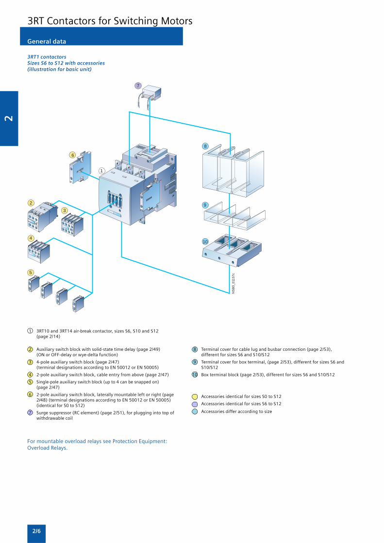
3RT1 contactorsSizes S6 to S12 with accessories(illustration for basic unit)
1 3RT10 and 3RT14 air-break contactor, sizes S6, S10 and S12(page 2/14)
2 Auxiliary switch block with solid-state time delay (page 2/49)(ON or OFF-delay or wye-delta function)
3 4-pole auxiliary switch block (page 2/47)(terminal designations according to EN 50012 or EN 50005)
4 2-pole auxiliary switch block, cable entry from above (page 2/47)
5 Single-pole auxiliary switch block (up to 4 can be snapped on)(page 2/47)
6 2-pole auxiliary switch block, laterally mountable left or right (page2/48) (terminal designations according to EN 50012 or EN 50005)(identical for S0 to S12)
7 Surge suppressor (RC element) (page 2/51), for plugging into top ofwithdrawable coil
8 Terminal cover for cable lug and busbar connection (page 2/53),different for sizes S6 and S10/S12
9 Terminal cover for box terminal, (page 2/53), different for sizes S6 andS10/S12
10 Box terminal block (page 2/53), different for sizes S6 and S10/S12
Accessories identical for sizes S0 to S12
Accessories identical for sizes S6 to S12
Accessories differ according to size
For mountable overload relays see Protection Equipment:Overload Relays.
General data
3RT Contactors for Switching Motors

2
2/7
NS
B0_
0166
9
1
2
1
3
5
6
3
4
3RA1 contactor assemblies, 3RT1 contactorsSizes S6, S10 and S12 with accessories
1 3RT10 and 3RT14 air-break contactor, sizes S6, S10 and S12 (page 2/14and 2/34) or 3RT12 vacuum contactor, sizes S10 and S12 (page 2/16)
2 Mechanical interlock, laterally mountable (page 2/23)
3 3RA19 wiring modules on the top and bottom (page 2/24)
4 3RT19 56-4BA31 link for paralleling (star jumper), 3-pole, with throughhole (page 2/52)
5 Terminal cover for box terminal, (page 2/53), different for sizes S6 andS10/S12
6 Terminal cover for cable lug and busbar connection (page 2/53),different for sizes S6 and S10/S12
Accessories identical for sizes S6 to S12
Accessories differ according to size
For mountable overload relays see Protection Equipment:Overload Relays.
General data
3RT Contactors for Switching Motors

2
2/8
3RT1 contactorsSizes S6 to S12 with accessories
1 Air-break contactor, sizes S6, S10 and S12 (page 2/15)
2 Vacuum contactor, sizes S10 and S12 (page 2/16)
3 Withdrawable coils for 3RT1. ..-.A.. contactors with conventionaloperating mechanism (Size S10: differentiation between 3RT10/3RT14air-break contactors and 3RT12 vacuum contactors)(Size S12: the same for air-break and vacuum contactors)
4 Withdrawable coils for 3RT1. ..-.N.. contactors with solid-stateoperating mech-anism (Size S10: differentiation between 3RT10/3RT14air-break contactors and 3RT12 vacuum contactors)(Size S12: the same for air-break and vacuum contactors)
5 Withdrawable coils and laterally mountable module (plug-on) for 3RT1...-.P.. and 3RT1. ..-.Q.. air-break contactors with solid-state operatingmechanism and remaining lifetime indicator
6 Surge suppressor (RC element) (page 2/51),plug-mountable on withdrawable coils• 3RT1...-.A.. with conventional operating mechanism• 3RT1...-.N.. with solid-state operating mechanism
Identical for sizes S6 to S12
Different according to size
For mountable overload relays see Protection Equipment:Overload Relays.
General data
3RT Contactors for Switching Motors

2
2/9
Overview
3RT10 contactors, 3-pole, sizes S00 to S3, up to 45 kW
AC and DC operation
IEC 60947, EN 60947 (VDE 0660)
The 3RT1 contactors are climate-proof. They are finger-safe
according to EN 50274.
Size S00 contactors have an auxiliary contact integrated in thebasic unit. The basic units of sizes S0 to S3 contain only themain current paths.
All basic units can be extended with auxiliary switch blocks.
For size S0 and higher, complete units with 2 NO + 2 NC areavailable (connection designation according to EN 50012). Theauxiliary switch block can be removed.
Contact reliability
If voltages ≤ 110 V and current ≤ 100 mA are to be switched,the auxiliary contacts of the 3RT1 contactor or 3RH11 contactorrelay should be used as they guarantee a high level of contactreliability.
These auxiliary contacts are suitable for solid-state circuits withcurrents ≥ 1 mA at a voltage of 17 V.
Short-circuit protection of the contactors
For more information about short-circuit protection ofcontactors without overload relay, see Technical specifications.For short-circuit protection of the contactors with overloadrelay, see “Overload Relays”. To assemble fuseless motorfeeders you must select combinations of motor starter protectorand contactor as explained in “Fuseless Load Feeders”.
Motor protection
3RU11 thermal overload relays or 3RB20 solid-state overloadrelays can be fitted to the 3RT1 contactors for protectionagainst overload. The overload relays must be orderedseparately.
Ratings of induction motors
The quoted rating (in kW) refers to the output power on themotor shaft (according to the nameplate).
Surge suppression
3RT1 contactors can be retrofitted with RC elements, varistors,diodes or diode assemblies (assembly of diode and Zener diodefor short break times) for damping opening surges in the coil.
The surge suppressors are plugged onto the front of size S00contactors. Space is provided for them next to a snap-onauxiliary switch block.
For size S0 to S3 contactors, varistors and RC elements can besnapped on either on the top or directly below the coilterminals. Diode assemblies are available in 2 different versionson account of their polarity. Depending on the application theycan be connected either only at the bottom (assembly withmotor starter protector) or only at the top (assembly withoverload relay).
The plug-in direction of the diodes and diode assemblies isspecified by coding.
3RT10 contactors, 3-pole, 3 ... 250 kW
Exceptions:
3RT19 26-1T . 00 and
3RT19 36-1T . 00, in this case the plug-in direction is markedwith “+” and “-”.
Coupling relays are supplied either without surge suppressionor with a varistor or diode connected as standard, according tothe version.
Note:The OFF-delay times of the NO contacts and the ON-delaytimes of the NC contacts increase if the contactor coils aredamped against voltage peaks (noise suppression diode 6 to10 times; diode assemblies 2 to 6 times, varistor +2 to 5 ms).
3RT10 contactors, 3-pole, sizes S6 to S12,> 45 to 250 kW
• 3RT10, contactors for switching motors,
• 3RT12, vacuum contactors for switching motors,
• 3RT14, contactors for AC-1 applications.
Operating mechanism types
Two types of solenoid operation are available:
• Conventional operating mechanism
• Solid-state operating mechanism (with 3 performance levels)
UC operation
The contactors can be operated with AC (40 to 60 Hz) as wellas with DC.
Withdrawable coils
For simple coil replacement, e.g. if the application is replaced,the magnetic coil can be pulled out upwards after the releasemechanism has been actuated and can be replaced by anyother coil of the same size.
Auxiliary contact complement
The contactors can be fitted with up to 8 auxiliary contacts(identical auxiliary switch blocks from S0 to S12). Of these, nomore than 4 are permitted to be NC contacts.
3RT10 and 3RT14 contactors:auxiliary contacts mounted laterally and on front3RT12 vacuum contactors:auxiliary contacts mounted laterally
Contactors with conventional operating mechanism
3RT1 . . . - . A version:
The magnetic coil is switched directly on and off with thecontrol supply voltage Us by way of terminals A1/A2.
Multi-voltage range for the control supply voltage Us:
Several closely adjacent control supply voltages, availablearound the world, are covered by just one coil,for example 110-115-120-127 V UC or 220-230-240 V UC.
In addition, allowance is also made for a coil operating range of0.8 times the lower (Us min) and 1.1 times the upper (Us max)rated control supply voltage within which the contactorswitches reliably and no thermal overloading occurs.
3RT Contactors for Switching Motors

2
2/10
3RT10 contactors, 3-pole, 3 ... 250 kW
Contactors with solid-state operating mechanism
The magnetic coil is supplied selectively with the powerrequired for reliable switching and holding by upstream controlelectronics.
• Wide voltage range for the control supply voltage Us:Compared with the conventional operating mechanism, thesolid-state operating mechanism covers an even broaderrange of control supply voltages used worldwide within onecoil variant.
For example, the coil for 200 to 277 V UC (Us min to Us max)covers the voltages 200-208-220-230-240-254-277 V usedworldwide.
• Extended operating range 0.7 to 1.25 x Us:The wide range for the rated control supply voltage and theadditionally allowed coil operating range of 0.8 x Us min to1.1 x Us max results in an extended coil operating range of atleast 0.7 to 1.25 x Us, within which the contactors willoperate reliably, for the most common control supplyvoltages of 24, 110 and 230 V.
• Bridging temporary voltage dips:Control voltage failures dipping to 0 V (at A1/A2) are bridgedfor up to approx. 25 ms to avoid unintentional tripping.
• Defined ON and OFF thresholds:For voltages of ≥ 0.8 x Us min and higher the electronics willreliably switch the contactor ON, and as of ≤ 0.5 x Us min it isreliably switched OFF. The hysteresis in the switchingthresholds prevents the main contacts from chattering as wellas increased wear or welding when operated in weak,unstable networks. This also prevents thermal overloading ofthe contactor coil if the voltage applied is too low (contactordoes not close properly and is continuously operated withoverexcitation).
• Low control power consumption when closing and in theclosed state.
Electromagnetic compatibility (EMC)
The contactors with solid-state operating mechanism complywith the requirements for operation in industrial plants.
• Interference immunity- burst (IEC 61000-4-4): 4 kV- surge (IEC 61000-4-5): 4 kV- electrostatic discharge, ESD (IEC 61000-4-2): 8/15 kV- electromagnetic field (IEC 61000-4-3): 10 V/m
• Emitted interference- limit value class A according to EN 55011
Note:In connection with converters, the control cables should beinstalled separately from the load cables of the converter.
Indication of remaining lifetime (RLT)
Main contactor contacts are working parts which must bereplaced in good time when the end of their service life hasbeen reached. The degree of contact erosion and thus theelectrical endurance (= number of operating cycles) depends onthe loading, utilization category, operating mode, etc. Routinechecks/visual inspections by the maintenance personnel areneeded in order to monitor the state of the main contacts. Theremaining lifetime indication function takes over this task. Itdoes not count the number of operating cycles – which doesnot provide information about contact erosion – but insteadelectronically identifies, evaluates and stores the actualprogress of erosion of each one of the three main contacts, and
outputs a warning when specified limits are reached. The storeddata are not lost even if the control supply voltage for A1/A2fails. After replacement of the main contacts, measurementthe remaining lifetime must be reset using the “RESET” button(hold down RESET button for about 2 seconds using a pen orsimilar tool).
Advantages:
• Signaling through relay contact or AS-i when remaininglifetime is 20 %, i.e. contact material wear is 80 %
• Additional visual indication of various levels of erosion bymeans of LEDs on the laterally mounted solid-state modulewhen remaining lifetime is 60 % (green), 40 % (orange) and20 % (red)
� � �
� � � � �
�
�
�
�
� � �
� � � � �
�
�
�
�
� � �
� � � � �
�
�
�
�
� � �
� � � � �
�
�
�
� � � � � � �
� � � �� � � � � � � �
� � � � �
� � � � �
� � �
� � � � � �
� �
• Early warning to replace contacts
• Optimum utilization of contact material
• Visual inspection of the condition of contacts no longernecessary
• Reduction of ongoing operating costs
• Optimum planning of maintenance measures
• Avoidance of unforeseen plant downtimes
3RT1 . . . - . N version: for 24 V DC PLC output
2 control options:
• Control without a coupling link directly through a 24 V DC/≥ 30 mA PLC output (EN 61131-2). Connection by means of2-pole plug-in connection. The screwless spring-typeconnection is part of the scope of supply. The control supplyvoltage which supplies the solenoid operating mechanismmust be connected to A1/A2.
Note:Before start-up, the slide switch for PLC operation must bemoved to the “PLC ON” position (setting ex works: “PLC OFF”).
DC 24 V
L1/L+N/L-
A1 A2
PLCOFF ON
1
2
NS
B0_
0114
3c
PLC outputDC 24 V/30 mA
Slide switch must be in“PLC ON” position
Plug-in connection, 2-pole
• Conventional control by applying the control supply voltageat A1/A2 through a switching contact.
3RT Contactors for Switching Motors

2
2/11
Note:The slide switch must be in the “PLC OFF” position(= setting ex works)
� ! " � � " #
� � $ � % $ � �
& � & �
' � !( ) ) (
�������*
�
Slide switch must be in“PLC OFF” position
3RT1 . . . - . P version: for 24 V DC PLC output or PLC relayoutput, with remaining lifetime indicator (RLT).
ON
H1H2
R1R2IN
IN24 VDC
RLT
300 VAC/DC
A1 A2
-.PP3.200-277 V
50-60 HzDC
RLT
60%
40%
20%
Reset
3RT105/3RT145
NS
B0_
0114
5b
Contactor ON
Displays for RLT:LED green
LED green
LED orange
LED red
RLT Reset
Plug-inconnection7-pole
To supply the solenoid and the remaining lifetime indicatorwith power, the control supply voltage Us must be connected toterminals A1/A2 of the laterally mounted solid-state module.The control inputs of the contactor are connected to a 7-poleplug-in connection; the screwless spring-operated connector ispart of the scope of supply.
• The “Remaining Lifetime RLT” status signal is available atterminals R1/R2 through a floating relay contact (hard gold-plated, enclosed) and can be input to SIMOCODE, PLC orother devices for processing, for example.Permissible current-carrying capacity of the R1/R2 relayoutput:- Ie/AC-15/24 to 230 V: 3 A- Ie/DC-13/24 V: 1 A
• LED indicationsThe following states are indicated by means of LEDs on thelaterally mounted solid-state module:- contactor ON (energized state): green LED (“ON”)- indication of remaining lifetime
L1/L+N/L-
A1 A2S2S1
S1
H1
R1R2ININ
H2
NSB0_01146d1 2
Indicationof remaininglifetime 20%
DC 24 V/30 mAPLC output
Solid-state module of3RT1. ..-.P contactor
Plug-in connection, 7-pole
S1 Selector switch for switchingfrom automatic control throughPLC semiconductor output tolocal control
S2 Local control option
Possibility of switching from automatic control to local controlby way of terminals H1/H2, i.e. automatic control through PLCor SIMOCODE/PROFIBUS DP can be deactivated e.g. at start-upor in the event of a fault and the contactor can be controlledmanually.
• Contactor control through relay outputs, e.g. by- PLC- SIMOCODE
by way of terminals H1/H2. Contact loading: Us/approx. 5 mA.When operated through SIMOCODE, a communication link toPROFIBUS DP is also provided.
2 control options:
• Contactor control without a coupling link directly through a 24 VDC/ ≥ 30 mA PLC output (EN 61131-2) by way of terminalsIN+/IN-.
L1/L+N/L-
A1 A2
H1H2
R1R2ININ
S1
S2
NSB0_01147c
PROFIBUS DP
1 2
e.g. SIMOCODE
otherPLC
Indicationof remaininglifetime 20%
Solid-state module of3RT1. ..-.P contactor
Plug-in connection, 7-pole
S1 Selector switch for switchingfrom automatic control, forexample, through SIMOCODE orPLC relay output to local control
S2 Local control option
3RT10 contactors, 3-pole, 3 ... 250 kW
3RT Contactors for Switching Motors

2
2/12
Selection and ordering data
3RT10 1 . -1A . . . 3RT10 1 . -1B . . .
AC Operation DC OperationRated data Auxiliary Rated control Screw terminals Weight Rated Screw terminals WeightAC-2 and AC-3, contacts supply per Piece control per PieceTu: up to 60 °C AC-1, voltage Us approx. supply approx.
Tu: 40 °C at 50/60 Hz2) voltage Us
Operational Ratings of Operational Ident. Version Order No. Order No.current Ie induction up to No.up to motors at 690 V415 V 50 Hz and
415 V
A kW A NO NC V AC kg V DC kg
For screw and snap-on mounting onto 35 mm standard mounting rail
Size S001)
Terminal designations according to EN 50012
7 3 18 10 E 1 — 24 3RT10 15-1AB01 0.200 24 3RT10 15-1BB41 0.260110 3RT10 15-1AF01 0.200 110 3RT10 15-1BF41 0.260230 3RT10 15-1AP01 0.200 220 3RT10 15-1BM41 0.2604002) 3RT10 15-1AV01 0.200
01 — 1 24 3RT10 15-1AB02 0.200 24 3RT10 15-1BB42 0.260110 3RT10 15-1AF02 0.200 110 3RT10 15-1BF42 0.260230 3RT10 15-1AP02 0.200 220 3RT10 15-1BM42 0.2604002) 3RT10 15-1AV02 0.200
9 4 22 10 E 1 — 24 3RT10 16-1AB01 0.200 24 3RT10 16-1BB41 0.260110 3RT10 16-1AF01 0.200 110 3RT10 16-1BF41 0.260230 3RT10 16-1AP01 0.200 220 3RT10 16-1BM41 0.2604002) 3RT10 16-1AV01 0.200
01 — 1 24 3RT10 16-1AB02 0.200 24 3RT10 16-1BB42 0.260110 3RT10 16-1AF02 0.200 110 3RT10 16-1BF42 0.260230 3RT10 16-1AP02 0.200 220 3RT10 16-1BM41 0.2604002) 3RT10 16-1AV02 0.200
12 5.5 22 10 E 1 — 24 3RT10 17-1AB01 0.200 24 3RT10 17-1BB41 0.260110 3RT10 17-1AF01 0.200 110 3RT10 17-1BF41 0.260230 3RT10 17-1AP01 0.200 220 3RT10 17-1BM41 0.2604002) 3RT10 17-1AV01 0.200
01 — 1 24 3RT10 17-1AB02 0.200 24 3RT10 17-1BB42 0.260110 3RT10 17-1AF02 0.200 110 3RT10 17-1BF42 0.260230 3RT10 17-1AP02 0.200 220 3RT10 17-1BM42 0.2004002) 3RT10 17-1AV02 0.200
For accessories, see page 3/45
1) For size S00: coil operating rangeat 50 Hz: 0.8 ... 1.1 x Us,at 60 Hz: 0.85 ... 1.1 x Us.
2) Coil operating frequency 50 Hz for 400V control supply voltage
3RT10 contactors, 3-pole, 3 ... 250 kW
3RT Contactors for Switching Motors
2
2/13
3RT10 2 . -1A .00. 3RT10 1 . -1B . . .
AC Operation DC OperationRated data Auxiliary Rated control Screw terminals Weight Rated Screw terminals WeightAC-2 and AC-3, contacts supply per Piece control per PieceTu: up to 60 °C AC-1, voltage Us approx. supply approx.
Tu: 40 °C at 50/60 Hz2) voltage Us
Operational Ratings of Operational Version Order No. Order No.current Ie induction up to up to motors at 690 V415 V 50 Hz and
415 V
A kW A NO NC V AC kg V DC kg
For screw and snap-on mounting onto 35 mm standard mounting rail
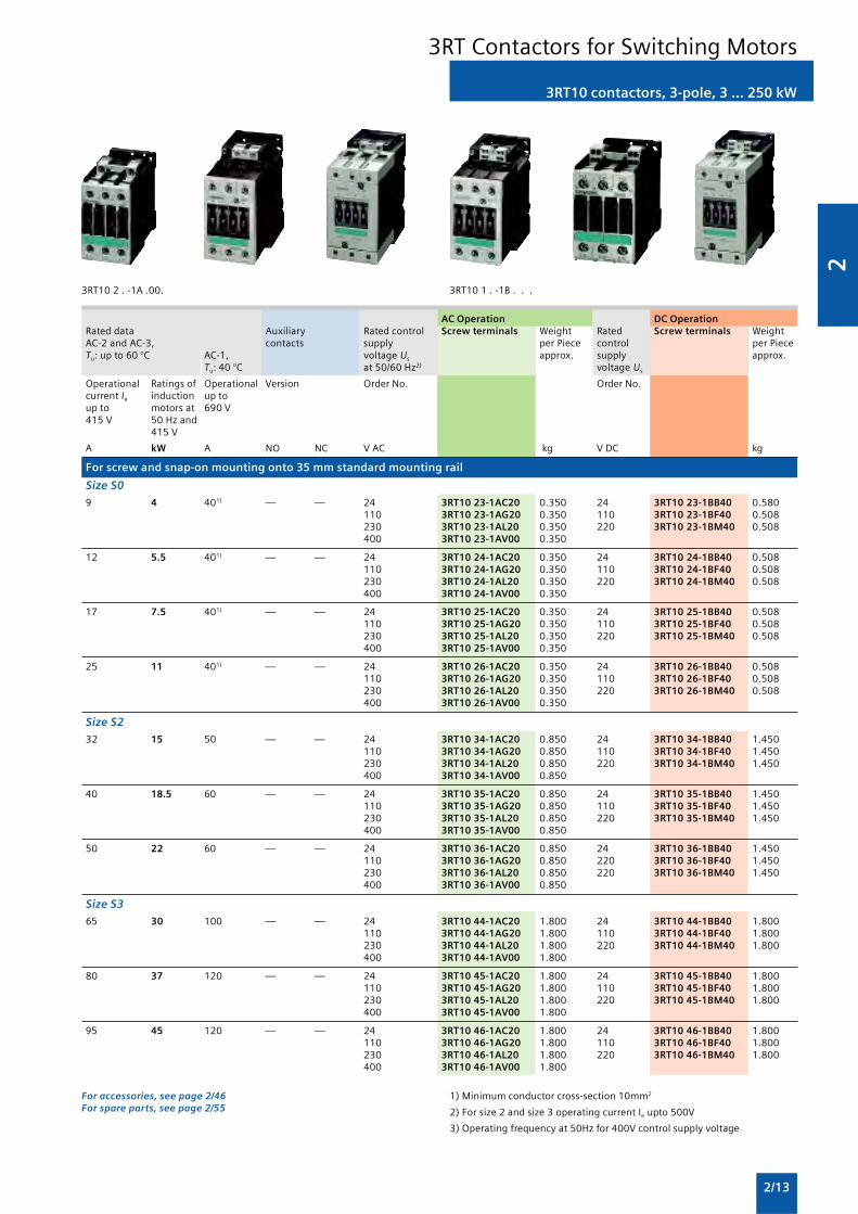
Size S0
9 4 401) — — 24 3RT10 23-1AC20 0.350 24 3RT10 23-1BB40 0.580110 3RT10 23-1AG20 0.350 110 3RT10 23-1BF40 0.508230 3RT10 23-1AL20 0.350 220 3RT10 23-1BM40 0.508400 3RT10 23-1AV00 0.350
12 5.5 401) — — 24 3RT10 24-1AC20 0.350 24 3RT10 24-1BB40 0.508110 3RT10 24-1AG20 0.350 110 3RT10 24-1BF40 0.508230 3RT10 24-1AL20 0.350 220 3RT10 24-1BM40 0.508400 3RT10 24-1AV00 0.350
17 7.5 401) — — 24 3RT10 25-1AC20 0.350 24 3RT10 25-1BB40 0.508110 3RT10 25-1AG20 0.350 110 3RT10 25-1BF40 0.508230 3RT10 25-1AL20 0.350 220 3RT10 25-1BM40 0.508400 3RT10 25-1AV00 0.350
25 11 401) — — 24 3RT10 26-1AC20 0.350 24 3RT10 26-1BB40 0.508110 3RT10 26-1AG20 0.350 110 3RT10 26-1BF40 0.508230 3RT10 26-1AL20 0.350 220 3RT10 26-1BM40 0.508400 3RT10 26-1AV00 0.350
Size S2
32 15 50 — — 24 3RT10 34-1AC20 0.850 24 3RT10 34-1BB40 1.450110 3RT10 34-1AG20 0.850 110 3RT10 34-1BF40 1.450230 3RT10 34-1AL20 0.850 220 3RT10 34-1BM40 1.450400 3RT10 34-1AV00 0.850
40 18.5 60 — — 24 3RT10 35-1AC20 0.850 24 3RT10 35-1BB40 1.450110 3RT10 35-1AG20 0.850 110 3RT10 35-1BF40 1.450230 3RT10 35-1AL20 0.850 220 3RT10 35-1BM40 1.450400 3RT10 35-1AV00 0.850
50 22 60 — — 24 3RT10 36-1AC20 0.850 24 3RT10 36-1BB40 1.450110 3RT10 36-1AG20 0.850 220 3RT10 36-1BF40 1.450230 3RT10 36-1AL20 0.850 220 3RT10 36-1BM40 1.450400 3RT10 36-1AV00 0.850
Size S3
65 30 100 — — 24 3RT10 44-1AC20 1.800 24 3RT10 44-1BB40 1.800110 3RT10 44-1AG20 1.800 110 3RT10 44-1BF40 1.800230 3RT10 44-1AL20 1.800 220 3RT10 44-1BM40 1.800400 3RT10 44-1AV00 1.800
80 37 120 — — 24 3RT10 45-1AC20 1.800 24 3RT10 45-1BB40 1.800110 3RT10 45-1AG20 1.800 110 3RT10 45-1BF40 1.800230 3RT10 45-1AL20 1.800 220 3RT10 45-1BM40 1.800400 3RT10 45-1AV00 1.800
95 45 120 — — 24 3RT10 46-1AC20 1.800 24 3RT10 46-1BB40 1.800110 3RT10 46-1AG20 1.800 110 3RT10 46-1BF40 1.800230 3RT10 46-1AL20 1.800 220 3RT10 46-1BM40 1.800400 3RT10 46-1AV00 1.800
For accessories, see page 2/46For spare parts, see page 2/55
1) Minimum conductor cross-section 10mm2
2) For size 2 and size 3 operating current Ie upto 500V
3) Operating frequency at 50Hz for 400V control supply voltage
3RT10 contactors, 3-pole, 3 ... 250 kW
3RT Contactors for Switching Motors

2
2/14
Contactors without coilsAC/DC operation (40 Hz to 60 Hz, DC)Conventional operating mechanism / Solid-state operating mechanism for 24 V DC PLC output
3RT1 . 5 . 3RT1 . 6 . 3RT1 . 7 .
Size Rated data Auxiliary Screw terminalsAC-2 and AC-3, AC-1, contacts,Tu: up to 60 °C Tu: 40 °C lateral
Operational Ratings of induction Operational Version Order No.current motors at 50 Hz and current Ie
Ie up to up to
500 V 230 V 400 V 500 V 690 V 690 V A kW kW kW kW A NO NC V AC/DC
Conventional operating mechanism
S6 115 37 55 75 110 160 2 2 3RT10 54-6LA06
150 45 75 90 132 185 2 2 3RT10 55-6LA06
185 55 90 110 160 215 2 2 3RT10 56-6LA06
S10 225 55 110 160 200 275 2 2 3RT10 64-6LA06
265 75 132 160 250 330 2 2 3RT10 65-6LA06
300 90 160 200 250 330 2 2 3RT10 66-6LA06
S12 400 132 200 250 400 430 2 2 3RT10 75-6LA06
500 160 250 355 400 610 2 2 3RT10 76-6LA06
Solid-state operating mechanism · for 24 V DC PLC output
For coils see page 2/54For other accessories see page 2/46For spare parts see page 2/55
3RT10 contactors, 3-pole, 3 ... 250 kW
3RT Contactors for Switching Motors

2
2/15
AC/DC operation (40 Hz to 60 Hz, DC)Auxiliary and control conductors: screw terminalsWithdrawable coilsIntegrated coil circuit (Varistor)Main conductors: busbar connections, for 3RT10 54 (55 kW) box terminals1)
Remaining lifetime indicator (RLT)
3RT10 56-6P . .
Size Rated data Auxiliary Rated control Screw terminals Weight perAC-2 and AC-3, AC-1, contacts, supply PU approx.Tu: up to 60 °C Tu: 40 °C lateral voltage Us
Operational Ratings of induction Operational Version Order No.current motors at 50 Hz and current Ie
Ie up to up to
500 V 230 V 415 V 500 V 690 V 690 V A kW kW kW kW A NO NC V AC/DC kg
Solid-state operating mechanism for 24 V DC PLC output/PLC relay output,with remaining lifetime indicator (RLT)
S6 115 37 55 75 110 160 1 1 96 … 127 3RT10 54-6PF35 4.000200 … 277 3RT10 54-6PP35 4.000
150 45 75 90 132 185 1 1 96 … 127 3RT10 55-6PF35 4.000200 … 277 3RT10 55-6PP35 4.000
185 55 90 110 160 215 1 1 96 … 127 3RT10 56-6PF35 4.000200 … 277 3RT10 56-6PP35 4.000
S10 225 55 110 160 200 275 1 1 96 … 127 3RT10 64-6PF35 7.000200 … 277 3RT10 64-6PP35 7.000
265 75 132 160 250 330 1 1 96 … 127 3RT10 65-6PF35 7.000200 … 277 3RT10 65-6PP35 7.000
300 90 160 200 250 330 1 1 96 … 127 3RT10 66-6PF35 7.000200 … 277 3RT10 66-6PP35 7.000
S12 400 132 200 250 400 430 1 1 96 … 127 3RT10 75-6PF35 10.500200 … 277 3RT10 75-6PP35 10.500
500 160 250 355 400 610 1 1 96 … 127 3RT10 76-6PF35 10.500200 … 277 3RT10 76-6PP35 10.500
For accessories see page 2/46.For spare parts see page 2/55.
3RT10 contactors, 3-pole, 3 ... 250 kW
3RT Contactors for Switching Motors

2
2/16
3RT12 vacuum contactors, 3-pole, 110 ... 250 kW
Overview
• 3RT12 vacuum contactors for switching motors
UC operationThe contactors can be operated with AC (40 to 60 Hz) as wellas with DC.
Withdrawable coilsFor simple coil replacement, e.g. if the application is replaced,the magnetic coil can be pulled out upwards after the releasemechanism has been actuated and can be replaced by anyother coil of the same size.Auxiliary contact complementThe contactors can be fitted with up to 8 lateral auxiliarycontacts (identical auxiliary switch blocks from S0 to S12). Ofthese, no more than 4 are permitted to be NC contacts.
Selection and ordering data
AC/DC operation (40 Hz to 60 Hz, DC)Auxiliary and control conductors: screw terminalsWithdrawable coilsIntegrated coil circuit (Varistor)Main conductors: busbar connections
3RT12 7 . 3RT12 7 .
Size Rated data Auxiliary Rated control Screw terminals WeightAC-2 and AC-3, AC-1, contacts, supply per pieceTu: up to 60 °C Tu: 40 °C lateral voltage Us approx.
Operational Ratings of induction Operational Version Order No.current Ie up to motors at 50 Hz and current Ie up to
1000 V 230 V 415 V 500 V 690 V 1000 V A kW kW kW kW A NO NC V AC/DC kg
Conventional operating mechanism
S10 225 55 110 160 200 330 2 2 23 … 26 3RT12 64-6AB36 7.3110 … 127 3RT12 64-6AF36 7.3220 … 240 3RT12 64-6AP36 7.3380 … 420 3RT12 64-6AV36 7.3
265 75 132 160 250 330 2 2 23 … 26 3RT12 65-6AB36 7.3110 … 127 3RT12 65-6AF36 7.3220 … 240 3RT12 65-6AP36 7.3380 … 420 3RT12 65-6AV36 7.3
300 90 160 200 250 330 2 2 23 … 26 3RT12 66-6AB36 7.3110 … 127 3RT12 66-6AF36 7.3220 … 240 3RT12 66-6AP36 7.3380 … 420 3RT12 66-6AV36 7.3
S12 400 132 200 250 400 610 2 2 23 … 26 3RT12 75-6AB36 10.5110 … 127 3RT12 75-6AF36 10.5220 … 240 3RT12 75-6AP36 10.5380 … 420 3RT12 75-6AV36 10.5
500 160 250 355 500 610 2 2 23 … 26 3RT12 75-6AB36 10.5110 … 127 3RT12 76-6AF36 10.5220 … 240 3RT12 76-6AP36 10.5380 … 420 3RT12 75-6AV36 10.5
For accessories, see page 2/46For spare parts, see page 2/55
1) Built-in surge suppression: varistor circuit.
2) For EMC please refer technical details or please contact Sales Office.
3RT Contactors for Switching Motors
2
2/17
Selection and ordering data
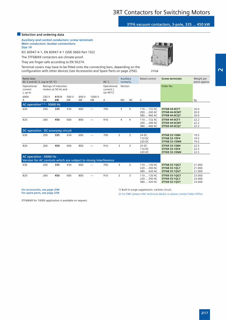
Auxiliary and control conductors: screw terminalsMain conductors: busbar connectionsSize 14
IEC 60947-4-1, EN 60947-4-1 (VDE 0660 Part 102)
The 3TF68/69 contactors are climate-proof.
They are finger-safe according to EN 50274.
Terminal covers may have to be fitted onto the connecting bars, depending on theconfiguration with other devices (see Accessories and Spare Parts on page 2/56). 3TF68
Rated data Auxiliary Rated control Screw terminals Weight perAC-2 and AC-3, (up to 55 °C) AC-1, contacts, piece approx.
Operational Ratings of induction Operational Version Order No.current motors at 50 Hz and current Ie
Ie up to (at 40°C)
690V 230 V 415 V 500 V 690 V 1000 VA kW kW kW kW kW A NO NC V kg
AC operation1) 2) · 50/60 Hz
630 200 335 434 600 — 700 4 4 110 … 132 AC 3TF68 44-0CF7 20.0200 … 240 AC 3TF68 44-0CM7 20.0380 … 460 AC 3TF68 44-0CQ7 20.0
820 260 450 600 800 — 910 4 4 110 … 132 AC 3TF69 44-0CF7 22.2200 … 240 AC 3TF69 44-0CM7 22.2380 … 460 AC 3TF69 44-0CQ7 22.2
DC operation · DC economy circuit
630 200 335 434 600 — 700 3 3 24 DC 3TF68 33-1DB4 19.5110 DC 3TF68 33-1DF4 19.5220 DC 3TF68 33-1DM4 19.5
820 260 450 600 800 — 910 3 3 24 DC 3TF69 33-1DB4 22.5110 DC 3TF69 33-1DF4 22.5220 DC 3TF69 33-1DM4 22.5
AC operation · 50/60 Hz ·Version for AC controls which are subject to strong interference
630 200 335 434 600 — 700 3 3 110 ... 120 AC 3TF68 33-1QG7 21.000220 ... 240 AC 3TF68 33-1QL7 21.000380 ... 420 AC 3TF68 33-1QV7 21.000
820 260 450 600 800 — 910 3 3 110 ... 120 AC 3TF69 33-1QG7 23.000220 ... 240 AC 3TF69 33-1QL7 23.000380 ... 420 AC 3TF69 33-1QV7 23.000
3TF6 vacuum contactors, 3-pole, 335 ... 450 kW
3RT Contactors for Switching Motors
For accessories, see page 2/46For spare parts, see page 2/56
1) Built-in surge suppression: varistor circuit.
2) For EMC please refer technical details or please contact Sales Office.
3TF68/69 for 1000V application is available on request.
2
2/18
Overview
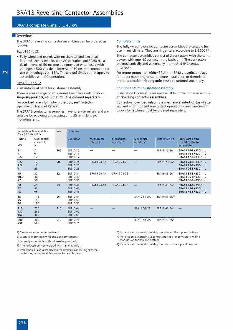
3RA13 complete units, 3 ... 45 kW
The 3RA13 reversing contactor assemblies can be ordered asfollows:
Sizes S00 to S3
• Fully wired and tested, with mechanical and electricalinterlock. For assemblies with AC operation and 50/60 Hz, adead interval of 50 ms must be provided when used withvoltages ≥ 500 V; a dead interval of 30 ms is recommend foruse with voltages ≥ 415 V. These dead times do not apply toassemblies with DC operation.
Sizes S00 to S12
• As individual parts for customer assembly.
There is also a range of accessories (auxiliary switch blocks,surge suppressors, etc.) that must be ordered separately.
For overload relays for motor protection, see “ProtectionEquipment: Overload Relays”.
The 3RA13 contactor assemblies have screw terminals and aresuitable for screwing or snapping onto 35 mm standardmounting rails.
Complete units
The fully wired reversing contactor assemblies are suitable foruse in any climate. They are finger-safe according to EN 50274.
The contactor assemblies consist of 2 contactors with the samepower, with one NC contact in the basic unit. The contactorsare mechanically and electrically interlocked (NC contactinterlock).
For motor protection, either 3RU11 or 3RB2 . overload relaysfor direct mounting or stand-alone installation or thermistormotor protection tripping units must be ordered separately.
Components for customer assembly
Installation kits for all sizes are available for customer assemblyof reversing contactor assemblies.
Contactors, overload relays, the mechanical interlock (as of sizeS0) and – for momentary-contact operation – auxiliary switchblocks for latching must be ordered separately.
Rated data AC-2 and AC-3 Size Order No.for AC 50 Hz 415 V
Rating Operational Contactor Mechanical Mechanical Mechanical Installation kit Fully wired andcurrent Ie interlock1) interlock2) interlock3) tested contactor
kW A assemblies
3 7 S00 3RT10 15 —4) — — 3RA19 13-2A5) 3RA13 15-8XB30-1 . .4 9 3RT10 16 3RA13 16-8XB30-1 . .5.5 12 3RT10 17 3RA13 17-8XB30-1 . .
5.5 12 S0 3RT10 24 3RA19 24-1A 3RA19 24-2B — 3RA19 23-2A6) 3RA13 24-8XB30-1 . .7.5 17 3RT10 25 3RA13 25-8XB30-1 . .11 25 3RT10 26 3RA13 26-8XB30-1 . .
15 32 S2 3RT10 34 3RA19 24-1A 3RA19 24-2B — 3RA19 33-2A7) 3RA13 34-8XB30-1 . .18.5 40 3RT10 35 3RA13 35-8XB30-1 . .22 50 3RT10 36 3RA13 36-8XB30-1 . .
30 65 S3 3RT10 44 3RA19 24-1A 3RA19 24-2B — 3RA19 43-2A7) 3RA13 44-8XB30-1 . .37 80 3RT10 45 3RA13 45-8XB30-1 . .45 95 3RT10 46 3RA13 46-8XB30-1 . .
55 115 S6 3RT10 54 — — 3RA19 54-2A 3RA19 53-2M8) —75 150 3RT10 5590 185 3RT10 56
110 225 S10 3RT10 64 — — 3RA19 54-2A 3RA19 63-2A8) —132 265 3RT10 65160 300 3RT10 66
200 400 S12 3RT10 75 — — 3RA19 54-2A 3RA19 73-2A8) —250 500 3RT10 76
3RA13 Reversing Contactor Assemblies
1) Can be mounted onto the front.
2) Laterally mountable with one auxiliary contact.
3) Laterally mountable without auxiliary contact.
4) Interlock can only be ordered with installation kit.
5) Installation kit contains: mechanical interlock; connecting clips for 2contactors; wiring modules on the top and bottom.
6) Installation kit contains: wiring modules on the top and bottom.
7) Installation kit contains: 2 connecting clips for contactors; wiringmodules on the top and bottom.
8) Installation kit contains: wiring module on the top and bottom.

2
2/19
3RA13 complete units, 3 ... 45 kW
Selection and ordering data
Fully wired and tested contactor assemblies2) · Size S00 · up to 5.5 kW
Rated data AC-2 and AC-3 Rated control Screw terminals Weight persupply voltage Us
1) PU approx.
Operational Ratings of induction Order No.current Ie up to motors at 50 Hz and415 V 230 V 415 V 500 V 690 V
A kW kW kW kW V kg
AC operation, 50/60 Hz
7 2-2 3 3.5 4 110 AC 3RA13 15-8XB30-1AF0 0.430230 AC 3RA13 15-8XB30-1AP0 0.430
9 3 4 4.5 5.5 110 AC 3RA13 16-8XB30-1AF0 0.430230 AC 3RA13 16-8XB30-1AP0 0.430
12 3 5.5 5.5 5.5 110 AC 3RA13 17-8XB30-1AF0 0.430230 AC 3RA13 17-8XB30-1AP0 0.430
DC operation
7 2-2 3 3.5 4 24 DC 3RA13 15-8XB30-1BB4 0.5509 3 4 4.5 5.5 24 DC 3RA13 16-8XB30-1BB4 0.550
3RA13 1 . -8XB30-1 . . .
1) Coil operating rangeat 50 Hz: 0.8 ... 1.1 x Us;at 60 Hz: 0.85 ... 1.1 x Us.
2) The contactors integrated in the contactor assemblies have nounassigned auxiliary contacts.
Accessories Order No. Page Individual parts Order No. Page
K1 K2
14 Auxiliary switch block, 1 2 Contactors, 3 kW 3RT10 15 3RT10 15 2/12front 3RH19 11-1.... 2/47 1 2 Contactors, 4 kW 3RT10 16 3RT10 16 2/12(auxiliary switch block
1 2 Contactors, 5.5 kW 3RT10 17 3RT10 17 2/12according to EN 500054 5 6 Installation kit 3RA19 13-2A 2/24must be used)
16 Surge suppressors 3RT19 16-1.... 2/51 The installation kit contains:
4 Mechanical interlock
5 2 connecting clips for 2 contactors
6 Wiring modules on the top and bottom for connectingthe main current paths, electrical interlock included1),interruptible (NC contact interlock)
1) 3RT10 1. contactors with one NC contact in the basic unit are requiredfor the electrical interlock.
Mountable accessories (to be ordered separately): The fully wired and tested contactor assembly includes the followingcomponents:
3RA13 Reversing Contactor Assemblies

2
2/20
�
�
�
�
�
��
��
��
��
��
��
��
3RA13 1 . -8XB30-1 . . .
Fully wired and tested contactor assemblies · Size S0 · up to 11 kW
Rated data AC-2 and AC-3 Rated control Screw terminals Weight persupply voltage Us
1) PU approx.
Operational Ratings of induction Order No.current Ie up to motors at 50 Hz and415 V 230 V 415 V 500 V 690 V
A kW kW kW kW V kg
AC operation, 50/60 Hz
12 3 5.5 7.5 7.5 110 AC 3RA13 24-8XB30-1AG2 0.770230 AC 3RA13 24-8XB30-1AL2 0.770
17 4 7.5 10 11 110 AC 3RA13 25-8XB30-1AG2 0.770230 AC 3RA13 25-8XB30-1AL2 0.770
25 5.5 11 11 11 110 AC 3RA13 26-8XB30-1AG2 0.770230 AC 3RA13 26-8XB30-1AL2 0.770
DC operation
12 3 5.5 7.5 7.5 24 DC 3RA13 24-8XB30-1BB4 1-23017 4 7.5 10 11 24 DC 3RA13 25-8XB30-1BB4 1-23025 5.5 11 11 11 24 DC 3RA13 26-8XB30-1BB4 1-230
1) Coil operating rangeat 50 Hz: 0.8 ... 1.1 x Us; at 60 Hz: 0.85 ... 1.1 x Us.
Accessories Order No. Page Individual parts Order No. Page
K1 K2
12 Mechanical interlock, front 3RA19 24-1A 2/23 1 2 Contactors, 5.5 kW 3RT10 24 3RT10 24 2/13
14 Auxiliary switch block, front 3RH19 21-1CA . . 2/47 1 2 Contactors, 7.5 kW 3RT10 25 3RT10 25 2/13
15 Auxiliary switch block, lateral 3RH19 21-1EA . . 2/48 1 2 Contactors, 11 kW 3RT10 26 3RT10 26 2/13
16 Surge suppressors 3RT19 26-1 . . . . 2/51 4 Mechanical interlock, 3RA19 24-2B 2/23lateral
6 Installation kit 3RA19 23-2A 2/24
The installation kit contains wiring modules on the top andbottom(they also form the mechanical connection betweenthe contactors).
Mountable accessories (to be ordered separately): The fully wired and tested contactor assembly includes the followingcomponents:
The connectingcables are notshown.
3RA13 complete units, 3 ... 45 kW
3RA13 Reversing Contactor Assemblies

2
2/21
�
�
�
�
�
��
�
��
���
��
��
��
��
3RA13 complete units, 3 ... 45 kW
Fully wired and tested contactor assemblies · Size S2 · up to 22 kW
Rated data AC-2 and AC-3 Rated control Screw terminals Weight persupply voltage Us
1) PU approx.
Operational Ratings of induction Order No.current Ie up to motors at 50 Hz and500 V 230 V 415 V 500 V 690 V
A kW kW kW kW V kg
AC operation, 50/60 Hz
32 7.5 15 18.5 18.5 110 AC 3RA13 34-8XB30-1AG2 2.300230 AC 3RA13 34-8XB30-1AL2 2.300
40 11 18.5 22 22 110 AC 3RA13 35-8XB30-1AG2 2.300230 AC 3RA13 35-8XB30-1AL2 2.300
50 15 22 30 22 110 AC 3RA13 36-8XB30-1AG2 2.300230 AC 3RA13 36-8XB30-1AL2 2.300
DC operation
32 7.5 15 18.5 18.5 24 DC 3RA13 34-8XB30-1BB4 3.45040 11 18.5 22 22 24 DC 3RA13 35-8XB30-1BB4 3.45050 15 22 30 22 24 DC 3RA13 36-8XB30-1BB4 3.450
1) Coil operating rangeat 50 Hz: 0.8 ... 1.1 x Us; at 60 Hz: 0.85 ... 1.1 x Us.
3RA13 3 . -8XB30-1 . . .
Mountable accessories (to be ordered separately): The fully wired and tested contactor assembly includes the followingcomponents:
The connectingcables are notshown.
Accessories Order No. Page Individual parts Order No. Page
K1 K2
12 Mechanical interlock, front 3RA19 24-1A 2/23 1 2 Contactors, 15 kW 3RT10 34 3RT10 34 2/13
14 Auxiliary switch block, front 3RH19 21-1CA . . 2/47 1 2 Contactors, 18.5 kW 3RT10 35 3RT10 35 2/13
15 Auxiliary switch block, lateral 3RH19 21-1EA . . 2/47 1 2 Contactors, 22 kW 3RT10 36 3RT10 36 2/13
16 Surge suppressors 3RT19 26-1 . . . . 2/51 4 Mechanical interlock, 3RA19 24-2B 2/233RT19 36-1 . . . . lateral
5 6 Installation kit 3RA19 33-2A
The installation kit contains: 2/24
5 2 connecting clips for 2 contactors with a clearanceof 10 mm
6 Wiring modules on the top and bottom for connectingthe main current paths
3RA13 Reversing Contactor Assemblies

2
2/22
�
�
�
�
�
�
��
��
��
��
��
��
���
Mountable accessories (to be ordered separately): The fully wired and tested contactor assembly includes the followingcomponents:
The connectingcables are notshown.
3RA13 complete units, 3 ... 45 kW
Fully wired and tested contactor assemblies · Size S3 · up to 45 kW
Rated data AC-2 and AC-3 Rated control Screw terminals Weight persupply voltage Us
1) PU approx.
Operational Ratings of induction Order No.current Ie up to motors at 50 Hz and500 V 230 V 415 V 500 V 690 V
A kW kW kW kW V kg
AC operation, 50/60 Hz
65 18.5 30 37 45 110 AC 3RA13 44-8XB30-1AG2 4.500230 AC 3RA13 44-8XB30-1AL2 4.500
80 22 37 45 55 110 AC 3RA13 45-8XB30-1AG2 4.500230 AC 3RA13 45-8XB30-1AL2 4.500
95 22 45 55 55 110 AC 3RA13 46-8XB30-1AG2 4.500230 AC 3RA13 46-8XB30-1AL2 4.500
DC operation
65 18.5 30 37 45 24 DC 3RA13 44-8XB30-1BB4 6.50080 22 37 45 55 24 DC 3RA13 45-8XB30-1BB4 6.50095 22 45 55 55 24 DC 3RA13 46-8XB30-1BB4 6.500
1) Coil operating rangeat 50 Hz: 0.8 ... 1.1 x Us; at 60 Hz: 0.85 ... 1.1 x Us.
3RA13 4 . -8XB30-1 . . .
Accessories Order No. Page Individual parts Order No. Page
K1 K2
12 Mechanical interlock, front 3RA19 24-1A 2/23 1 2 Contactors, 30 kW 3RT10 44 3RT10 44 2/13
14 Auxiliary switch block, front 3RH19 21-1CA . . 2/47 1 2 Contactors, 37 kW 3RT10 45 3RT10 45 2/13
15 Auxiliary switch block, lateral 3RH19 21-1EA . . 2/47 1 2 Contactors, 45 kW 3RT10 46 3RT10 46 2/13
16 Surge suppressors 3RT19 26-1 . . . . 2/51 4 Mechanical interlock, 3RA19 24-2B 2/233RT19 36-1 . . . . lateral
5 6 Installation kit 3RA19 43-2A 2/24
The installation kit contains:
5 2 connecting clips for 2 contactors with a clearanceof 10 mm
6 Wiring modules on the top and bottom for connectingthe main current paths
3RA13 Reversing Contactor Assemblies

2
2/23
Components for customer assembly
For Size Version Order No. Weight percontactors PU approx.
Type kg
Mechanical interlocks
3RT10 2 S0 For lateral mounting1) 3RA19 24-2B 0.0603RT10 3 S2 Each with one auxiliary contact (1 NC contact)3RT10 4 S3 per contactor (can only be used to connect3RT13 2 contactors which are not more than 1 size3RT13 3 larger or smaller. The mounting depth of the3RT13 4 smaller contactor has to be adapted.)3RT15 23RT15 3
3RT10 2 S0 For mounting to the front2) 3RA19 24-1A 0.0503RT10 3 S2 Onto contactors with sizes S0 to S33RT10 4 S3 (for contactors of the same size)3RT13 2 S0 Note:3RT15 2 Size S0: Wiring modules must be mounted first
Sizes S2 and S3: Use 3RA19 32-2Cmechanical connectors
3RT1 . 5 S6 For lateral mounting 3RA19 54-2A 0.050to S10 Without auxiliary contacts; size S6, S10 and3RT1 . 7 S12 S12 contactors can be interlocked with each other
as required; no adaptation of mounting depthis necessary. Contactor clearance 10 mm.
3RT10 4 . -A S3 Adapters, laterally mountable 3RA19 54-2C 0.050with with For mechanical interlocking of contactor S33RT10 5 S6 (only for AC operation) with contactor S6 using
3RA19 54-2A locking device (must be orderedseparately) incl. connecting clips.
Base plates
3RT10 5 S6 For customer assembly of reversing 3RA19 52-2A 1.3003RT1 . 6 S10 contactor assemblies 3RA19 62-2A 2.1003RT1 . 7 S12 3RA19 72-2A 2.300
1) Can also be used for 4-pole contactors with sizes S2 and S3.
2) Can also be used for size S0 4-pole contactors.
Selection and ordering data
3RA19 24-1A mountedonto 2 contactors
3RA19 54-2A
3RA19 54-2C
3RA13 Reversing Contactor Assemblies
2
2/24
For Size Version Order No. Weight percontactors PU approx.
Type kg
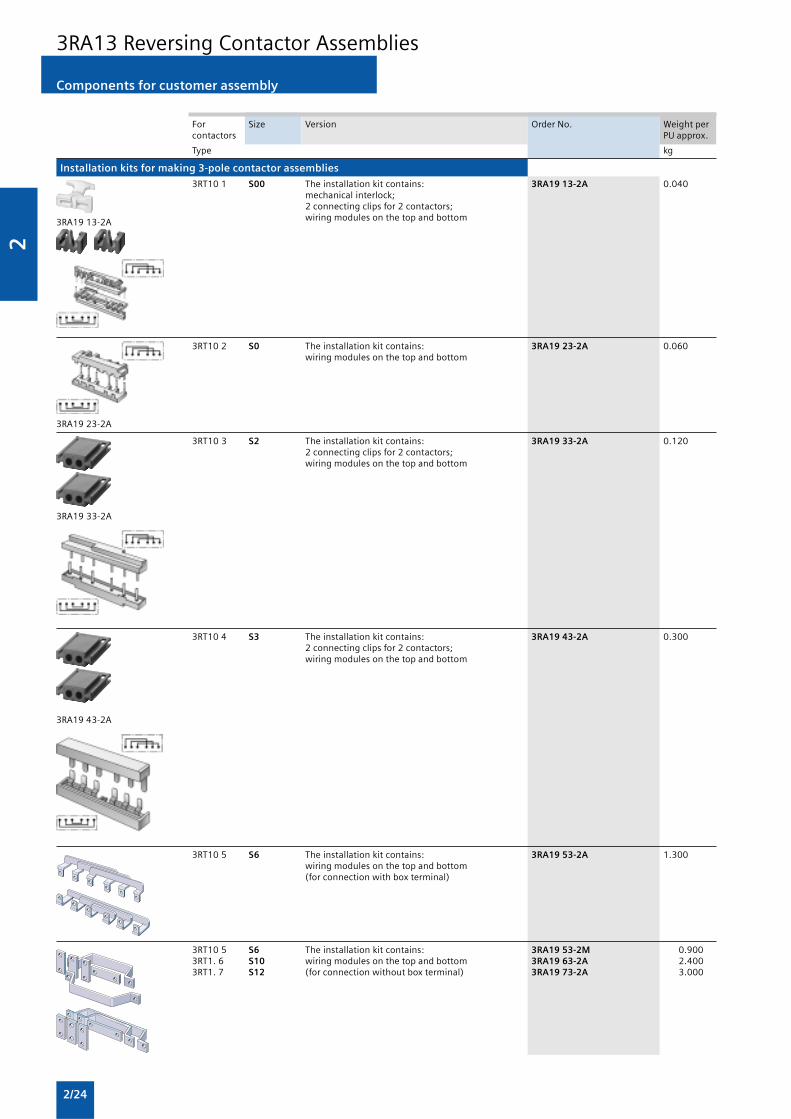
Installation kits for making 3-pole contactor assemblies
3RT10 1 S00 The installation kit contains: 3RA19 13-2A 0.040mechanical interlock;2 connecting clips for 2 contactors;wiring modules on the top and bottom
3RT10 2 S0 The installation kit contains: 3RA19 23-2A 0.060wiring modules on the top and bottom
3RT10 3 S2 The installation kit contains: 3RA19 33-2A 0.1202 connecting clips for 2 contactors;wiring modules on the top and bottom
3RT10 4 S3 The installation kit contains: 3RA19 43-2A 0.3002 connecting clips for 2 contactors;wiring modules on the top and bottom
3RT10 5 S6 The installation kit contains: 3RA19 53-2A 1.300wiring modules on the top and bottom(for connection with box terminal)
3RT10 5 S6 The installation kit contains: 3RA19 53-2M 0.9003RT1. 6 S10 wiring modules on the top and bottom 3RA19 63-2A 2.4003RT1. 7 S12 (for connection without box terminal) 3RA19 73-2A 3.000
3RA19 13-2A
3RA19 23-2A
3RA19 33-2A
3RA19 43-2A
Components for customer assembly
3RA13 Reversing Contactor Assemblies

2
2/25
For Size Contactor Version Order No. Weight percontactors clearance PU approx.
Type mm kg
Wiring modules, single
3RT10 1 S00-S00 0 top (in-phase) 3RA19 13-3D 0.015bottom (with phase reversal) 3RA19 13-3E 0.015
3RT10 2 S0-S0 0 and10 top (in-phase) 3RA19 23-3D 0.020and bottom (with phase reversal) 3RA19 23-3E 0.020S0-S0
3RT10 3 S2-S2 10 top (in-phase) 3RA19 33-3D 0.065bottom (with phase reversal) 3RA19 33-3E 0.065
3RT10 4 S3-S3 10 top (in-phase) 3RA19 43-3D 0.160bottom (with phase reversal) 3RA19 43-3E 0.160
3RT10 5 S6-S6 10 top (in-phase, for connection 3RA19 53-3D 0.620with box terminal)
top (with phase reversal, for 3RA19 53-3P 0.440connection without box terminal)
3RA19 53-3D
3RA19 53-3P
For Size Contactor Interlocking Version Order No. Weight percontactors clearance PU approx.
Type mm kg
Mechanical connectors 1 pack = 10 sets for 10 assemblies
3RT1. 11) S00-S00 0 laterally for 3- and 4-pole 3RA19 12-2H 0.010mountable contactors
3RA19 12-2H
3RT1. 2 S0-S0 0 mountable for 3- and 4-pole 3RA19 22-2C 0.025102) on front contactors
laterally 3RT19 22-2D 0.110mountable
3RA19 22-2C
3RT1. 3 S2-S2 0 mountable for 3-pole 3RA19 32-2C 0.0103RT1. 4 S3-S3 on front contactors
3RA19 32-2C
3RT1. 3 S2-S2 10 laterally for 3-pole 3RA19 32-2D 0.0103RT1. 4 S3-S3 mountable contactors3RT1. 5 S6-S6
3RA19 32-2D
3RT1. 3 S2-S2 10 laterally for 4-pole 3RA19 32-2G 0.010mountable contactors
3RA19 32-2G
3RT1. 4 S3-S3 10 laterally for 4-pole 3RA19 42-2G 0.010mountable contactors
3RA19 42-2G
1) This pack contains 10 additional interlocks.
2) The connector function can be fulfilled with the wiring modules for sizeS0, a contactor clearance of 10 mm and a lateral interlock.
Components for customer assembly
3RA13 Reversing Contactor Assemblies
2
2/26
3RA14 complete units, 3 ... 75 kW
Overview
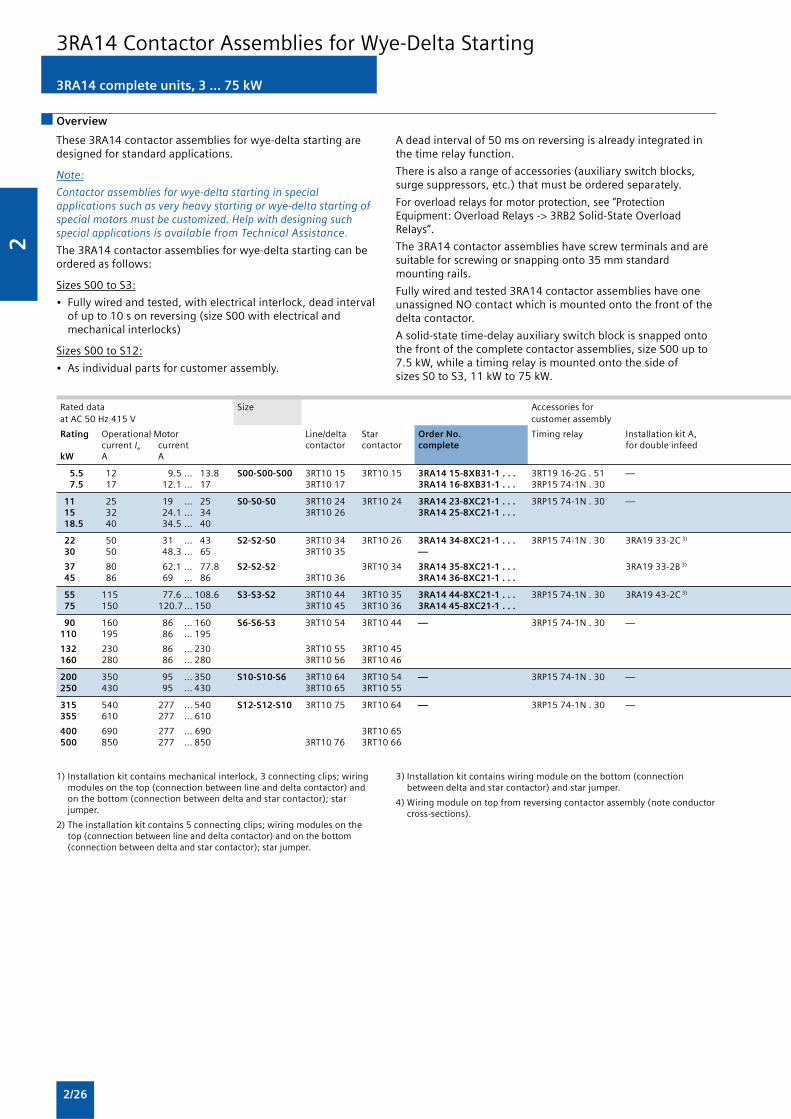
These 3RA14 contactor assemblies for wye-delta starting aredesigned for standard applications.
Note:
Contactor assemblies for wye-delta starting in specialapplications such as very heavy starting or wye-delta starting ofspecial motors must be customized. Help with designing suchspecial applications is available from Technical Assistance.
The 3RA14 contactor assemblies for wye-delta starting can beordered as follows:
Sizes S00 to S3:
• Fully wired and tested, with electrical interlock, dead intervalof up to 10 s on reversing (size S00 with electrical andmechanical interlocks)
Sizes S00 to S12:
• As individual parts for customer assembly.
A dead interval of 50 ms on reversing is already integrated inthe time relay function.
There is also a range of accessories (auxiliary switch blocks,surge suppressors, etc.) that must be ordered separately.
For overload relays for motor protection, see “ProtectionEquipment: Overload Relays -> 3RB2 Solid-State OverloadRelays”.
The 3RA14 contactor assemblies have screw terminals and aresuitable for screwing or snapping onto 35 mm standardmounting rails.
Fully wired and tested 3RA14 contactor assemblies have oneunassigned NO contact which is mounted onto the front of thedelta contactor.
A solid-state time-delay auxiliary switch block is snapped ontothe front of the complete contactor assemblies, size S00 up to7.5 kW, while a timing relay is mounted onto the side ofsizes S0 to S3, 11 kW to 75 kW.
Rated data Size Accessories forat AC 50 Hz 415 V customer assembly
Rating Operational Motor Line/delta Star Order No. Timing relay Installation kit A,current Ie current contactor contactor complete for double infeed
kW A A
5.5 12 9.5 ... 13.8 S00-S00-S00 3RT10 15 3RT10 15 3RA14 15-8XB31-1 . . . 3RT19 16-2G . 51 — 7.5 17 12.1 ... 17 3RT10 17 3RA14 16-8XB31-1 . . . 3RP15 74-1N . 30
11 25 19 ... 25 S0-S0-S0 3RT10 24 3RT10 24 3RA14 23-8XC21-1 . . . 3RP15 74-1N . 30 — 15 32 24.1 ... 34 3RT10 26 3RA14 25-8XC21-1 . . . 18.5 40 34.5 ... 40
22 50 31 ... 43 S2-S2-S0 3RT10 34 3RT10 26 3RA14 34-8XC21-1 . . . 3RP15 74-1N . 30 3RA19 33-2C 3)
30 50 48.3 ... 65 3RT10 35 —
37 80 62.1 ... 77.8 S2-S2-S2 3RT10 34 3RA14 35-8XC21-1 . . . 3RA19 33-2B 3)
45 86 69 ... 86 3RT10 36 3RA14 36-8XC21-1 . . .
55 115 77.6 ... 108.6 S3-S3-S2 3RT10 44 3RT10 35 3RA14 44-8XC21-1 . . . 3RP15 74-1N . 30 3RA19 43-2C 3)
75 150 120.7 ... 150 3RT10 45 3RT10 36 3RA14 45-8XC21-1 . . .
90 160 86 ... 160 S6-S6-S3 3RT10 54 3RT10 44 — 3RP15 74-1N . 30 —110 195 86 ... 195
132 230 86 ... 230 3RT10 55 3RT10 45160 280 86 ... 280 3RT10 56 3RT10 46
200 350 95 ... 350 S10-S10-S6 3RT10 64 3RT10 54 — 3RP15 74-1N . 30 —250 430 95 ... 430 3RT10 65 3RT10 55
315 540 277 ... 540 S12-S12-S10 3RT10 75 3RT10 64 — 3RP15 74-1N . 30 —355 610 277 ... 610
400 690 277 ... 690 3RT10 65500 850 277 ... 850 3RT10 76 3RT10 66
1) Installation kit contains mechanical interlock, 3 connecting clips; wiringmodules on the top (connection between line and delta contactor) andon the bottom (connection between delta and star contactor); starjumper.
2) The installation kit contains 5 connecting clips; wiring modules on thetop (connection between line and delta contactor) and on the bottom(connection between delta and star contactor); star jumper.
3) Installation kit contains wiring module on the bottom (connectionbetween delta and star contactor) and star jumper.
4) Wiring module on top from reversing contactor assembly (note conductorcross-sections).
3RA14 Contactor Assemblies for Wye-Delta Starting

2
2/27
3RA14 complete units, 3 ... 75 kW
Components for customer assembly
Installation kits with wiring modules and, if necessary,mechanical connectors are available for contactor assembliesfor wye-delta starting. Contactors, overload relays, wye-deltatiming relays, auxiliary switches for electrical interlock – ifrequired also feeder terminals, mechanical interlocks(exception: In the case of the installation kit for size S00contactor assemblies the mechanical interlock between thedelta contactor and the star contactor is included in the kit) andbase plates – must be ordered separately.
The wiring kits for sizes S00 and S0 contain the top and bottommain conducting path connections between the line and deltacontactors (top) and between the delta and star contactors(bottom).
In the case of sizes S2 to S12 only the bottom main conductingpath connection between the delta and star contactors is
included in the wiring module, owing to the larger conductorcross-section at the infeed.
Motor protection
Overload relays or thermistor motor protection tripping unitscan be used for overload protection.
The overload relay can be either mounted onto the linecontactor or separately fitted. It must be set to 0.58 times therated motor current.
3RA14 Contactor Assemblies for Wye-Delta Starting
Overload relay, thermal Overload relay, solid-state(trip class CLASS 10) (trip class CLASS 10)
Installation kit B, Star jumper Base plates Setting range Order No. Setting range Order No.for single infeed
A A
3RA19 13-2B1) 3RT19 16-4BA31 — 5.5 ... 8 3RU11 16-1HB0 3 ... 12 3RB20 16-1SB07 ... 10 3RU11 16-1JB0
3RA19 23-2B2) 3RT19 26-4BA31 — 11 ... 16 3RU11 26-4AB0 6 ... 25 3RB20 26-1QB014 .. 20 3RU11 26-4BB020 ... 25 3RU11 26-4DB0
3RV19 35-1A 3RT19 26-4BA31 3RA19 32-2E 18 ... 25 3RU11 36-4DB0 12.5 ... 50 3RB20 36-1UB028 ... 40 3RU11 36-4FB0
3RT19 36-4BA31 3RA19 32-2F 36 ... 45 3RU11 36-4GB040 ... 50 3RU11 36-4HB0
— 3RT19 36-4BA31 3RA19 42-2E 45 ... 63 3RU11 46-4JB0 25 ...100 3RB20 46-1EB070 ... 90 3RU11 46-4LB0
3RA19 53-3D4) 3RT19 46-4BA31 3RA19 52-2E — — 50 ...200 3RB20 56-1FC2
— 3RT19 56-4BA31 3RA19 62-2E — — 55 ...250 3RB20 66-1GC2
— 3RT19 66-4BA31 3RA19 72-2E — — 160 ...630 3RB20 66-1MC2
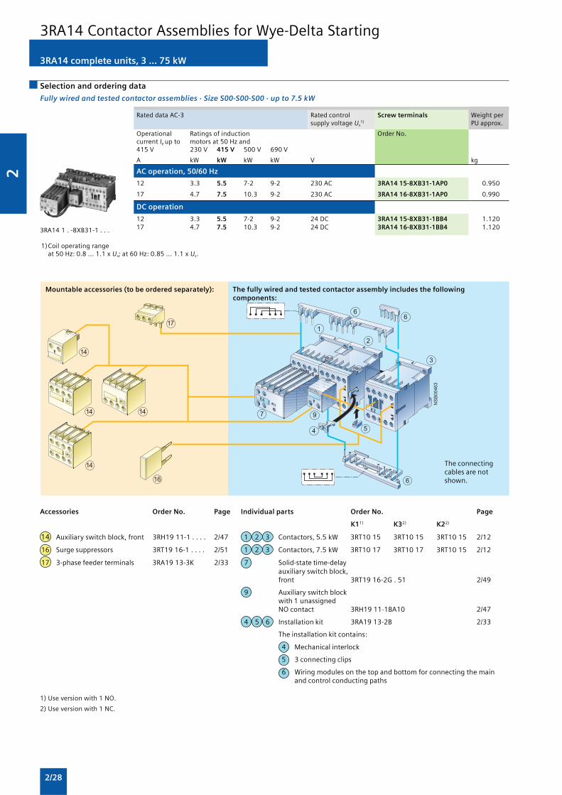
2
2/28
�
�
��
�
�
�
��
�
��
�� ��
��
��
��
���
Mountable accessories (to be ordered separately): The fully wired and tested contactor assembly includes the followingcomponents:
3RA14 complete units, 3 ... 75 kW
Selection and ordering data
Fully wired and tested contactor assemblies · Size S00-S00-S00 · up to 7.5 kW
Rated data AC-3 Rated control Screw terminals Weight persupply voltage Us
1) PU approx.
Operational Ratings of induction Order No.current Ie up to motors at 50 Hz and415 V 230 V 415 V 500 V 690 V
A kW kW kW kW V kg
AC operation, 50/60 Hz
12 3.3 5.5 7-2 9-2 230 AC 3RA14 15-8XB31-1AP0 0.950
17 4.7 7.5 10.3 9-2 230 AC 3RA14 16-8XB31-1AP0 0.990
DC operation
12 3.3 5.5 7-2 9-2 24 DC 3RA14 15-8XB31-1BB4 1.12017 4.7 7.5 10.3 9-2 24 DC 3RA14 16-8XB31-1BB4 1.120
1)Coil operating rangeat 50 Hz: 0.8 ... 1.1 x Us; at 60 Hz: 0.85 ... 1.1 x Us.
3RA14 1 . -8XB31-1 . . .
Accessories Order No. Page Individual parts Order No. Page
K11) K32) K22)
14 Auxiliary switch block, front 3RH19 11-1 . . . . 2/47 1 2 3 Contactors, 5.5 kW 3RT10 15 3RT10 15 3RT10 15 2/12
16 Surge suppressors 3RT19 16-1 . . . . 2/51 1 2 3 Contactors, 7.5 kW 3RT10 17 3RT10 17 3RT10 15 2/12
17 3-phase feeder terminals 3RA19 13-3K 2/33 7 Solid-state time-delayauxiliary switch block,front 3RT19 16-2G . 51 2/49
9 Auxiliary switch blockwith 1 unassignedNO contact 3RH19 11-1BA10 2/47
4 5 6 Installation kit 3RA19 13-2B 2/33
The installation kit contains:
4 Mechanical interlock
5 3 connecting clips
6 Wiring modules on the top and bottom for connecting the mainand control conducting paths
1) Use version with 1 NO.
2) Use version with 1 NC.
The connectingcables are notshown.
3RA14 Contactor Assemblies for Wye-Delta Starting

2
2/29
NS
B0_
0046
4a
21
3
6
8
19
6 65
16
7
12
17
18
1010
15
1094
19
Mountable accessories (to be ordered separately): The fully wired and tested contactor assembly includes the followingcomponents:
The connectingcables are notshown.
3RA14 complete units, 3 ... 75 kW
Fully wired and tested contactor assemblies · Size S0-S0-S0 · up to 18.5 kW
Rated data AC-3 Rated control Screw terminals Weight persupply voltage Us
1) PU approx.
Operational Ratings of induction Order No.current Ie up to motors at 50 Hz and415 V 230 V 415 V 500 V 690 V
A kW kW kW kW V kg
AC operation, 50/60 Hz
25 7.1 11 15.6 19 230 AC 3RA14 23-8XC21-1AL2 1.800
32 / 40 11.4 15 / 18.5 19 19 230 AC 3RA14 25-8XC21-1AL2 1.800
DC operation
25 7.1 11 15.6 19 24 DC 3RA14 23-8XC21-1BB4 2.450
32 / 40 11.4 15 / 18.5 19 19 24 DC 3RA14 25-8XC21-1BB4 2.450
1) Coil operating range at 50 Hz:0.8 ... 1.1 x Us ; at 60 Hz: 0.85 ... 1.1 x Us.
3RA14 2 . -8XC21-1 . . .
1) Generally possible. If a solid-state time-delay auxiliary switch block ismounted onto the front of K3, a standard auxiliary switch block can onlybe mounted onto the side.
2) 17 and 18 can only be mounted with contactors with screw terminal(coil).
3) Not part of the scope of supply of the preassembled contactorassemblies; can be ordered as an accessory.
4) See Monitoring and Control Devices: 3RP, 7PV timing relays -> 3RP15timing relays in 22.5 mm industrial enclosure.
Accessories Order No. Page Individual parts Order No. Page
K1 K3 K2
1 Mechanical interlock, lateral 3RA19 24-2B 2/23 1 2 3 Contactors, 11 kW 3RT10 24 3RT10 24 3RT10 24 2/13
7 Solid-state time-delay 1 2 3 Contactors, 15/18.5 kW 3RT10 26 3RT10 26 3RT10 24 2/13auxiliary switch block, front1) 3RT19 26-2G . . . 2/49
12 Mechanical interlock, front 3RA19 24-1A 2/23 8 Timing relay, lateral 3RP15 74-1N . 30 4)
15 Auxiliary switch block, lateral 3RH19 21-1EA . . 2/48 9 Auxiliary switch block with1 unassigned NO contact 3RH19 21-1CA10 2/47
16 Surge suppressors 3RT19 26-1 . . . . 2/51 10 Auxiliary switch blockfor local control
17 3-phase feeder terminal2) 3RV19 15-5A 2/33 2 units 3RH19 21-1CA01
18 3-phase busbar2) 3RT19 26-4CC20 2/333 units 3RH19 21-1CA10
2/47
19 Push-in lug3) for timing relay 5 6 Installation kit 3RA19 23-2B 2/33screw mounting 3RP19 03 4)
The installation kit contains:
5 Connecting clips
6 Wiring modules on the top and bottom for connecting the mainand control conducting paths
3RA14 Contactor Assemblies for Wye-Delta Starting

2
2/30
NS
B0_
0046
5b
2
1
3
6
11
8
616
7
17
18
1010
15
109
4
19
Mountable accessories (to be ordered separately): The fully wired and tested contactor assembly includes the followingcomponents:
The connectingcables are notshown.
Fully wired and tested contactor assemblies · Size S2-S2-S0 · up to 30 kW
Rated data AC-3 Rated control Screw terminals Weight persupply voltage Us
1) PU approx.
Operational Ratings of induction Order No.current Ie up to motors at 50 Hz and415 V 230 V 415 V 500 V 690 V
A kW kW kW kW V kg
AC operation, 50/60 Hz
50 / 65 19.6 22 / 30 35 34 230 AC 3RA14 34-8XC21-1AL2 3.100
DC operation
50 / 65 19.6 22 / 30 35 34 24 DC 3RA14 34-8XC21-1BB4 4.500
1) Coil operating range at 50 Hz: 0.8 ... 1.1 x Us; at 60 Hz: 0.85 ... 1.1 x U
s.
3RA14 34-8XC21-1 . . .
1) Use the 3RA19 32-2B base plate for this configuration.
2) Generally possible. If a solid-state time-delay auxiliary switch block ismounted onto the front of K3, a standard auxiliary switch block can onlybe mounted onto the side.
3) Not part of the scope of supply of the preassembled contactorassemblies; can be ordered as an accessory.
4) See Monitoring and Control Devices: 3RP, 7PV timing relays -> 3RP15timing relays in 22.5 mm industrial enclosure.
Accessories Order No. Page
4 Mechanical interlock, lateralDepth compensation requiredK3: 1.5 mm; K2: 0 mm1) 3RA19 24-2B 2/23
7 Solid-state time-delayauxiliary switch block, front2) 3RT19 26-2G . . . 2/49
15 Auxiliary switch block, lateral 3RH19 21-1EA . . 2/48
16 Surge suppressors 3RT19 26-1 . . . . 2/513RT19 36-1 . . . .
17 3-phase feeder terminal 3RV19 35-5A 2/33
18 3-phase busbars 3RV19 35-1A 2/33
19 Push-in lug3) for timing relayscrew mounting 3RP19 03 4)
Individual parts Order No. Page
K1 K3 K2
1 2 3 Contactors, 22/30 kW 3RT10 34 3RT10 34 3RT10 26 2/13
8 Timing relay, lateral 3RP15 74-1N . 30 4)
9 Auxiliary switch block with 3RH19 21-1CA10 2/471 unassigned NO contact
10 Auxiliary switch block forlocal control2 units 3RH19 21-1CA01 2/473 units 3RH19 21-1CA10
11 Base plate 3RA19 32-2E 2/33
6 Installation kit 3RA19 33-2C 2/33
The installation kit contains the star jumper on the top and the wiringmodule on the bottom for connecting the main current paths.
3RA14 complete units, 3 ... 75 kW
3RA14 Contactor Assemblies for Wye-Delta Starting

2
2/31
NS
B0_
0046
6a
17
18
16
15
109
19
11
3
621
1010
8
612
4
7
Mountable accessories (to be ordered separately): The fully wired and tested contactor assembly includes the followingcomponents:
The connectingcables are notshown.
Fully wired and tested contactor assemblies · Size S2-S2-S2 · up to 45 kW
Rated data AC-3 Rated control Screw terminals Weight persupply voltage Us
1) PU approx.
Operational Ratings of induction Order No.current Ie up to motors at 50 Hz and415 V 230 V 415 V 500 V 690 V
A kW kW kW kW V kg
AC operation, 50/60 Hz
80 25 37 51 63 230 AC 3RA14 35-8XC21-1AL2 3.700
86 27 45 55 63 230 AC 3RA14 36-8XC21-1AL2 3.700
DC operation
80 25 37 51 63 24 DC 3RA14 35-8XC21-1BB4 5.500
86 27 45 55 63 24 DC 3RA14 36-8XC21-1BB4 5.500
1) Coil operating range at 50 Hz: 0.8 ... 1.1 x Us; at 60 Hz: 0.85 ... 1.1 x Us.
3RA14 3 . -8XC21-1 . . .
1) Generally possible. If a solid-state time-delay auxiliary switch block ismounted onto the front of K3, a standard auxiliary switch block can onlybe mounted onto the side.
2) Not part of the scope of supply of the preassembled contactorassemblies; can be ordered as an accessory.
3) See Monitoring and Control Devices: 3RP, 7PV timing relays -> 3RP15timing relays in 22.5 mm industrial enclosure.
Accessories Order No. Page
4 Mechanical interlock, lateral 3RA19 24-2B 2/23
7 Solid-state time-delayauxiliary switch block, front1) 3RT19 26-2G . . . 2/49
12 Mechanical interlock, front 3RA19 24-1A 2/23
15 Auxiliary switch block, lateral 3RH19 21-1EA . . 2/48
16 Surge suppressors 3RT19 26-1 . . . . 2/513RT19 36-1 . . . .
17 3-phase feeder terminals 3RV19 35-5A 2/33
18 3-phase busbars 3RV19 35-1A 2/33
19 Push-in lug2) for timing relayscrew mounting 3RP19 03 3)
Individual parts Order No. Page
K1 K3 K2
1 2 3 Contactors, 37 kW 3RT10 35 3RT10 35 3RT10 34 2/13
1 2 3 Contactors, 45 kW 3RT10 36 3RT10 36 3RT10 34 2/13
8 Timing relay, lateral 3RP15 74-1N . 30 3)
9 Auxiliary switch block with1 unassigned NO contact 3RH19 21-1CA10 2/47
10 Auxiliary switch block forlocal control2 units 3RH19 21-1CA013 units 3RH19 21-1CA10 2/47
11 Base plate 3RA19 32-2F 2/33
6 Installation kit 3RA19 33-2B 2/33
The installation kit contains the star jumper on the top and the wiringmodule on the bottom for connecting the main current paths.
3RA14 complete units, 3 ... 75 kW
3RA14 Contactor Assemblies for Wye-Delta Starting

2
2/32
NS
B0_
0046
7d
8
21
3
6
7
10 10
6
11
9
10
16
15
4
19
20
Mountable accessories (to be ordered separately): The fully wired and tested contactor assembly includes the followingcomponents:
The connectingcables are notshown.
Fully wired and tested contactor assemblies · Size S2-S3-S2 · up to 75 kW
Rated data AC-3 Rated control Screw terminals Weight persupply voltage Us
1) PU approx.
Operational Ratings of induction Order No.current Ie up to motors at 50 Hz and415 V 230 V 415 V 500 V 690 V
A kW kW kW kW V kg
AC operation, 50/60 Hz
115 37 55 81 93 230 AC 3RA14 44-8XC21-1AL2 6.000
150 47 75 103 110 230 AC 3RA14 45-8XC21-1AL2 6.000
DC operation
115 37 55 81 93 24 DC 3RA14 44-8XC21-1BB4 8.600
150 47 75 103 110 24 DC 3RA14 45-8XC21-1BB4 8.600
1) Coil operating range at 50 Hz: 0.8 ... 1.1 x Us; at 60 Hz: 0.85 ... 1.1 x Us.
3RA14 4 . -8XC21-1 . . .
1) Use the 3RA19 42-2B base plate for this configuration.
2) Generally possible. If a solid-state time-delay auxiliary switch block ismounted onto the front of K3, a standard auxiliary switch block can onlybe mounted onto the side.
3) Not part of the scope of supply of the preassembled contactorassemblies; can be ordered as an accessory.
4) See Monitoring and Control Devices: 3RP, 7PV timing relays -> 3RP15timing relays in 22.5 mm industrial enclosure.
Accessories Order No. Page
4 Mechanical interlock, lateral 3RA19 24-2B 2/23Depth compensation requiredK3: 0 mm; K2: 27.5 mm1)
7 Solid-state time-delayauxiliary switch block, front2) 3RT19 26-2G . . . 2/49
15 Auxiliary switch block, lateral 3RH19 21-1EA . . 2/48
16 Surge suppressors 3RT19 . 6-1 . . . . 2/51
19 Push-in lug3) for timing relayscrew mounting 3RP19 03 4)
20 1-phase feeder terminal 3RA19 43-3L 2/33
Individual parts Order No. Page
K1 K3 K2
1 2 3 Contactors, 55 kW 3RT10 44 3RT10 44 3RT10 35 2/13
1 2 3 Contactors, 75 kW 3RT10 45 3RT10 45 3RT10 36 2/13
8 Timing relay, lateral 3RP15 74-1N . 30 4)
9 Auxiliary switch block with1 unassigned NO contact 3RH19 21-1CA10 2/47
10 Auxiliary switch block forlocal control2 units 3RH19 21-1CA013 units 3RH19 21-1CA10 2/47
11 Base plate 3RA19 42-2E 2/33
6 Installation kit 3RA19 43-2C 2/33
The installation kit contains the star jumper on the top and the wiringmodule on the bottom for connecting the main current paths.
3RA14 complete units, 3 ... 75 kW
3RA14 Contactor Assemblies for Wye-Delta Starting

2
2/33
Version Size Order No. Weight perPU approx.
Type kg
Installation kits
The installation kit contains: S00-S00-S00 3RA19 13-2B 0.050mechanical interlock;3 connecting clipsstar jumper,wiring modules on the top and bottom
The installation kit contains: S0-S0-S0 3RA19 23-2B 0.0605 connecting clips star jumper,wiring modules on the top and bottom
The installation kit contains: S2-S2-S0 3RA19 33-2C 0.060star jumper, S2-S2-S2 3RA19 33-2B 0.070wiring module on the bottom S3-S3-S2 3RA19 43-2C 0.140
(Wiring module on the top is not included S3-S3-S3 3RA19 43-2B 0.160in the scope of supply. A double infeed S6-S6-S6 3RA19 53-2B 0.850between the line contactor and thedelta contactor is recommended.)
S6-S6-S6 3RA19 53-2N 0.600
S10-S10-S10 3RA19 63-2B 1.800
S12-S12-S12 3RA19 73-2B 2-200
1-phase feeder terminals
Conductor cross-section: 95 mm2 S3 3RA19 43-3L 0-280
3-phase feeder terminals
Feeder terminal block for the line contactorfor large conductor cross-sections
Conductor cross-section: 6 mm2 S00 3RA19 13-3K 0.020Conductor cross-section: 25 mm2 S0 3RV19 15-5A 0.040Conductor cross-section: 50 mm2 S2 3RV19 35-5A 0.110
3-phase busbars
Bridging phase-by-phase of all input terminals of
The line contactor (K1) and S0 3RT19 26-4CC20 0.030The delta contactor (K3) S2 3RV19 35-1A 0.150
Links for paralleling, 3-pole (star jumpers)
Without connection terminal S00 3RT19 16-4BA31 0.010(the links for paralleling can be S0 3RT19 26-4BA31 0.010reduced by one pole) S2 3RT19 36-4BA31 0.020
S3 3RT19 46-4BA31 0.030S61) 3RT19 56-4BA31 0.160S10, S121) 3RT19 66-4BA31 0.500
Base plates
For customer assembly of contactor assembliesfor wye-delta starting with a laterally mountedtiming relay
Side-by-side mounting S2, S2, S0 3RA19 32-2E 0.45010 mm distance between K3 and K2 S2, S2, S2 3RA19 32-2F 0.480Side-by-side mounting S3, S3, S2 3RA19 42-2E 0.870
10 mm distance between K1, K3 and K2 S6, S6, S6 3RA19 52-2F 1.950
S10, S10, S10 3RA19 62-2F 3.400S12, S12, S12 3RA19 72-2F 3.700
For customer assembly of contactor assemblies S2, S2, S0 3RA19 32-2B 0.450for wye-delta starting with a front-mounted S2, S2, S2 3RA19 32-2B 0.450timing relay, 10 mm distance between S3, S3, S2 3RA19 42-2B 0.700K1, K3 and K2
Components for customer assembly
Selection and ordering data
3RA19 53-2B
3RA19 53-2N,3RA19 63-2B,3RA19 73-2B
3RT19 26-4BA31
1) The 3RT19 56-4EA1 (S6) or 3RT19 66-4EA1 (S10, S12) cover can be usedfor touch protection.
3RA14 Contactor Assemblies for Wye-Delta Starting

2
2/34
3-pole, 140 ... 690 A
3RT14 Contactors for Switching Resistive Loads (AC-1)
Overview
AC and DC operation (size S3)
UC operation (AC/DC) (sizes S6 to S12)
IEC 60947, EN 60947 (VDE 0660)
The contactors are suitable for use in any climate. They arefinger-safe according to EN 50274.
3RT14 contactors are used for switching resistive loads (AC-1) oras contactors, for example, for variable-speed operatingmechanisms that normally only have to carry the current.
The accessories for the 3RT10 contactors can also be used here.
For more detailed descriptions about the sizes S3 to S12,see 3RT10 Contactors, 3-pole, 3 to 250 kW.
Selection and ordering data
Size Rated data AC-1, Tu: 40 °C Rated control Screw terminals Weight persupply voltage PU approx.
Operational Ratings of AC loads Us Order No.current Ie up to (p.f. = 0.95) at690 V 230 V 400 V 500 V 690 V
A kW kW kW kW V kg
For screw and snap-on mounting onto 35 mm and 75 mm standard mounting rail
AC operation
S3 140 53 92 115 159 24 AC, 50/60 Hz 3RT14 46-1AC20 1.850110 AC, 50/60 Hz 3RT14 46-1AG00 1.850230 AC, 50/60 Hz 3RT14 46-1AL00 1.850400 AC, 50 Hz 3RT14 46-1AV00 1.850
DC operation · DC solenoid system
S3 140 53 92 115 159 24 DC 3RT14 46-1BB40 2.800110 DC 3RT14 46-1BF40 2.800220 DC 3RT14 46-1BM40 2.800
3RT14 46-1A..0
AC/DC operation (40 Hz to 60 Hz, DC)Auxiliary and control conductors: screw terminalsWithdrawable coilsIntegrated coil circuit (Varistor)Main conductors: busbar connections
Size Rated data AC-1, Tu: 40 °C Auxiliary Rated control Screw terminals Weight percontacts supply voltage PU approx.
Operational Ratings of AC loads Version Us Order No.current Ie up to (p.f. = 0.95) at690 V 230 V 400 V 500 V 690 V NO NC
A kW kW kW kW V kg
Conventional operating mechanisms
S6 275 105 180 225 310 2 2 23 ... 26 3RT14 56-6AB36 3.3602 2 110 … 127 3RT14 56-6AF36 3.3602 2 220 … 240 3RT14 56-6AP36 3.360
S10 400 151 263 329 454 2 2 23 … 26 3RT14 66-6AB36 6.6002 2 110 … 127 3RT14 66-6AF36 6.6002 2 220 … 240 3RT14 66-6AP36 6.600
S12 690 261 454 568 783 2 2 23 … 26 3RT14 76-6AB36 10.5002 2 110 … 127 3RT14 76-6AF36 10.5002 2 220 … 240 3RT14 76-6AP36 10.500
3RT14 6.
For accessories, see page 2/46.For spare parts, see page 2/55.
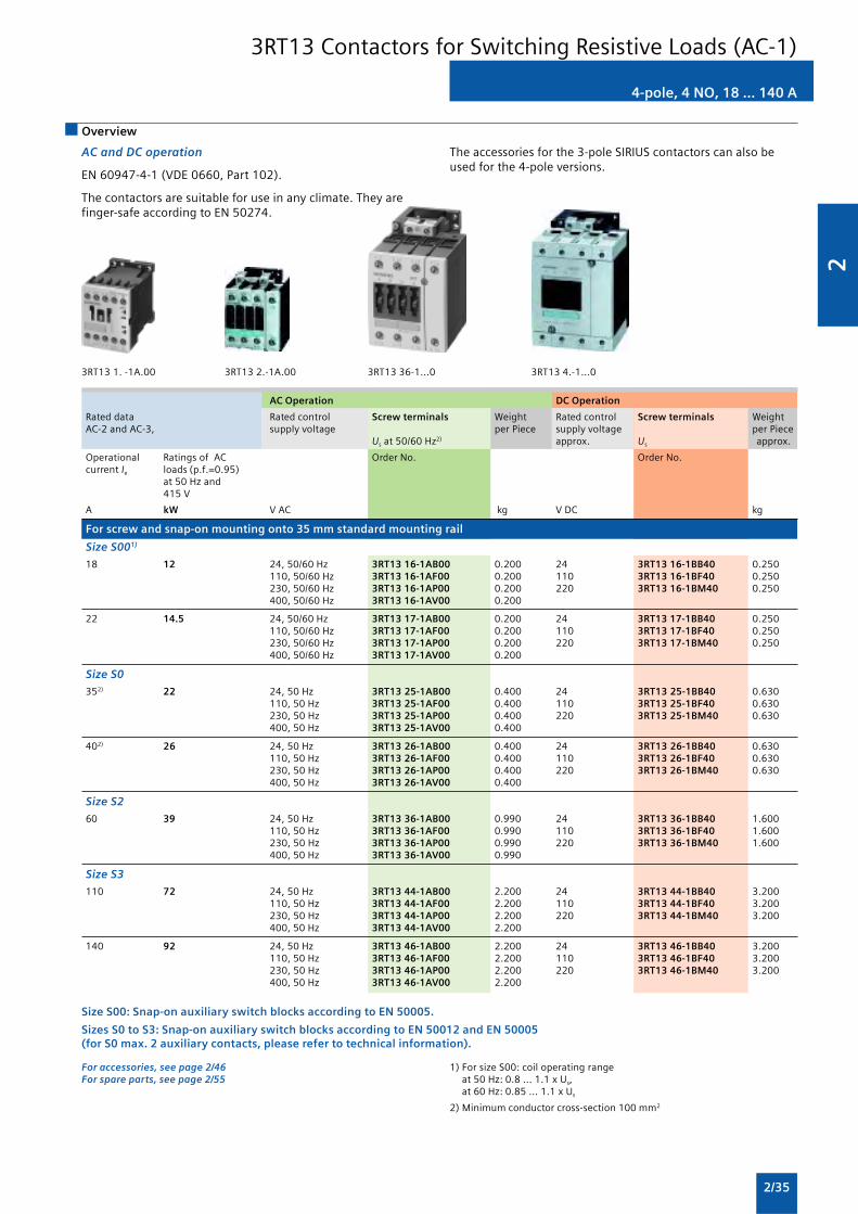
2
2/35
3RT13 1. -1A.00 3RT13 2.-1A.00
AC Operation DC Operation
Rated data Rated control Screw terminals Weight Rated control Screw terminals WeightAC-2 and AC-3, supply voltage per Piece supply voltage per Piece
Us at 50/60 Hz2) approx. Us approx.
Operational Ratings of AC Order No. Order No.current Ie loads (p.f.=0.95)
at 50 Hz and415 V
A kW V AC kg V DC kg
For screw and snap-on mounting onto 35 mm standard mounting rail
Size S001)
18 12 24, 50/60 Hz 3RT13 16-1AB00 0.200 24 3RT13 16-1BB40 0.250110, 50/60 Hz 3RT13 16-1AF00 0.200 110 3RT13 16-1BF40 0.250230, 50/60 Hz 3RT13 16-1AP00 0.200 220 3RT13 16-1BM40 0.250400, 50/60 Hz 3RT13 16-1AV00 0.200
22 14.5 24, 50/60 Hz 3RT13 17-1AB00 0.200 24 3RT13 17-1BB40 0.250110, 50/60 Hz 3RT13 17-1AF00 0.200 110 3RT13 17-1BF40 0.250230, 50/60 Hz 3RT13 17-1AP00 0.200 220 3RT13 17-1BM40 0.250400, 50/60 Hz 3RT13 17-1AV00 0.200
Size S0
352) 22 24, 50 Hz 3RT13 25-1AB00 0.400 24 3RT13 25-1BB40 0.630110, 50 Hz 3RT13 25-1AF00 0.400 110 3RT13 25-1BF40 0.630230, 50 Hz 3RT13 25-1AP00 0.400 220 3RT13 25-1BM40 0.630400, 50 Hz 3RT13 25-1AV00 0.400
402) 26 24, 50 Hz 3RT13 26-1AB00 0.400 24 3RT13 26-1BB40 0.630110, 50 Hz 3RT13 26-1AF00 0.400 110 3RT13 26-1BF40 0.630230, 50 Hz 3RT13 26-1AP00 0.400 220 3RT13 26-1BM40 0.630400, 50 Hz 3RT13 26-1AV00 0.400
Size S2
60 39 24, 50 Hz 3RT13 36-1AB00 0.990 24 3RT13 36-1BB40 1.600110, 50 Hz 3RT13 36-1AF00 0.990 110 3RT13 36-1BF40 1.600230, 50 Hz 3RT13 36-1AP00 0.990 220 3RT13 36-1BM40 1.600400, 50 Hz 3RT13 36-1AV00 0.990
Size S3
110 72 24, 50 Hz 3RT13 44-1AB00 2.200 24 3RT13 44-1BB40 3.200110, 50 Hz 3RT13 44-1AF00 2.200 110 3RT13 44-1BF40 3.200230, 50 Hz 3RT13 44-1AP00 2.200 220 3RT13 44-1BM40 3.200400, 50 Hz 3RT13 44-1AV00 2.200
140 92 24, 50 Hz 3RT13 46-1AB00 2.200 24 3RT13 46-1BB40 3.200110, 50 Hz 3RT13 46-1AF00 2.200 110 3RT13 46-1BF40 3.200230, 50 Hz 3RT13 46-1AP00 2.200 220 3RT13 46-1BM40 3.200400, 50 Hz 3RT13 46-1AV00 2.200
Size S00: Snap-on auxiliary switch blocks according to EN 50005.
Sizes S0 to S3: Snap-on auxiliary switch blocks according to EN 50012 and EN 50005(for S0 max. 2 auxiliary contacts, please refer to technical information).
For accessories, see page 2/46For spare parts, see page 2/55
1) For size S00: coil operating rangeat 50 Hz: 0.8 ... 1.1 x Us,at 60 Hz: 0.85 ... 1.1 x Us
2) Minimum conductor cross-section 100 mm2
4-pole, 4 NO, 18 ... 140 A
Overview
AC and DC operation
EN 60947-4-1 (VDE 0660, Part 102).
The contactors are suitable for use in any climate. They arefinger-safe according to EN 50274.
The accessories for the 3-pole SIRIUS contactors can also beused for the 4-pole versions.
3RT13 36-1...0 3RT13 4.-1...0
3RT13 Contactors for Switching Resistive Loads (AC-1)

2
2/36
Overview
EN 60947-4-1 (VDE 0660 Part 102)
The contactors also comply with the requirements of
NFC 63-110 and NFC 20–040.
The contactors are suitable for use in any climate. They are finger-safe according to EN 50274. Terminal covers may have to befitted onto the connecting bars, depending on the configurationwith other devices.
Magnetic coils for 3TK10 to 3TK13 contactors: as withdrawablecoils.
Surge suppression
Control circuit
Magnetic coils for 3TK1 contactors: can be retrofitted with
RC elements.
4-pole, 4 NO, 200 ... 1000 A
Selection and ordering data
Screw terminalsScrew mounting
3TK13
Rated data AC-1 Auxiliary Rated control Screw terminals Weight percontacts supply voltage Us piece approx.
Operational Ratings of AC loads Version Order No.current Ie (p f. = 0.95) atup to 690V
230 V 415 V 690 V 1000 VA kW kW kW kW NO NC V AC kg
AC operation
200 75 130 225 205 2 2 230 ... 240, 50 Hz 3TK10 42-0AU0 4.400110/120 V, 50/60 Hz 3TK10 42-0AF0 4.40024, 50 Hz 3TK10 42-0AB0 4.400
250 90 165 280 200 2 2 230 ... 240, 50 Hz 3TK11 42-0AU0 4.700110/120 V, 50/60 Hz 3TK11 42-0AF0 4.70024, 50 Hz 3TK11 42-0AB0 4.700
300 110 195 340 325 2 2 230 ... 240, 50 Hz 3TK12 42-0AU0 7.200110/120 V, 50/60 Hz 3TK12 42-0AF0 7.20024, 50 Hz 3TK12 42-0AB0 7.200
350 130 230 395 370 2 2 230 ... 240, 50 Hz 3TK13 42-0AU0 7.200110/120 V, 50/60 Hz 3TK13 42-0AF0 7.20024, 50 Hz 3TK13 42-0AB0 7.200
550 205 360 620 510 2 2 230 ... 240, 50 Hz 3TK14 42-0AU0 19.000110/120, 50/60 Hz 3TK14 42-0AF0 19.000
800 300 525 905 575 2 2 230 ... 240, 50 Hz 3TK15 42-0AU0 19.000110/120, 50/60 Hz 3TK15 42-0AF0 19.000
1000 375 655 1135 — 2 2 230 ... 240, 50 Hz 3TK17 42-0AU0 20.100110/120 50/60 Hz 3TK17 42-0AF0 20.100
For accessories, see page 2/60For spare parts, see page 2/60
3TK1 Contactors for Switching Resistive Loads (AC-1)

2
2/37
AC and DC operation
EN 60947-4-1 (VDE 0660, Part 102).
4-pole, 2 NO + 2 NC, 4 ... 18.5 kW
Overview
The contactors are suitable for use in any climate. They arefinger- safe according to EN 50274.
The accessories for the 3-pole SIRIUS contactors can also beused for the 4-pole versions.
Selection and ordering data
AC and DC operation, 2 NO contacts + 2 NC contacts1)
3RT15 1 . -1 . . . . 3RT15 26-1 . . . .
Rated data Rated control Screw terminals Weight perAC-2/AC-3, Tu: up to 60 °C AC-1, Tu: 40 °C supply voltage Us piece approx.
Operational Ratings of induction Operational Order No.current Ie motors at 50 Hz and current Ie
at 415 V 415 VA kW A V kg
For screw and snap-on mounting onto 35 mm standard mounting rail
AC operation
Size S002)
9 4 18 24, 50/60 Hz 3RT15 16-1AB00 0.200110, 50/60 Hz 3RT15 16-1AF00 0.200230, 50/60 Hz 3RT15 16-1AP00 0.200400, 50/60 Hz 3RT15 16-1AV00 0.200
12 5.5 22 24, 50/60 Hz 3RT15 17-1AB00 0.200110, 50/60 Hz 3RT15 17-1AF00 0.200230, 50/60 Hz 3RT15 17-1AP00 0.200400, 50/60 Hz 3RT15 17-1AV00 0.200
Size S0
25 11 40 24, 50 Hz 3RT15 26-1AB00 0.400110, 50 Hz 3RT15 26-1AF00 0.400230, 50 Hz 3RT15 26-1AP00 0.400400, 50 Hz 3RT15 26-1AV00 0.400
Size S2
40 18.5 55 24, 50 Hz 3RT15 35-1AB00 1.000110, 50 Hz 3RT15 35-1AF00 1.000230, 50 Hz 3RT15 35-1AP00 1.000400, 50 Hz 3RT15 35-1AV00 1.000
DC operation · DC solenoid system
Size S00
9 4 18 24 DC 3RT15 16-1BB40 0.260110 DC 3RT15 16-1BF40 0.260220 DC 3RT15 16-1BM40 0.260
12 5.5 22 24 DC 3RT15 17-1BB40 0.260110 DC 3RT15 17-1BF40 0.260220 DC 3RT15 17-1BM40 0.260
Size S0
20 11 40 24 DC 3RT15 26-1BB40 0.630110 DC 3RT15 26-1BF40 0.630220 DC 3RT15 26-1BM40 0.630
Size S2
40 18.5 55 24 DC 3RT15 35-1BB40 1.590110 DC 3RT15 35-1BF40 1.590220 DC 3RT15 35-1BM40 1.590
Size S00: snap-on auxiliary switch blocks according to EN 50005.Sizes S0 to S3: snap-on auxiliary switch blocks according to EN 50012 and EN 50005(for S0 max. 2 auxiliary contacts, please note information in the Technical Information).
For accessories, see page 2/46For spare parts, see page 2/55
1) Single device for pole reversal; not suitable for reversing duty.
2) For size S00: coil operating rangeat 50 Hz: 0.8 ... 1.1 x Us
at 60 Hz: 0.85 ... 1.1 x Us.
3RT15 Contactors
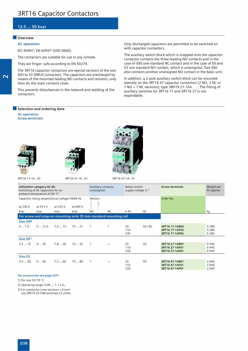
2
2/38
12.5 ... 50 kvar
AC operation
IEC 60947, EN 60947 (VDE 0660).
The contactors are suitable for use in any climate.
They are finger- safe according to EN 50274.
The 3RT16 capacitor contactors are special versions of the sizeS00 to S3 SIRIUS contactors. The capacitors are precharged bymeans of the mounted leading NO contacts and resistors; onlythen do the main contacts close.
This prevents disturbances in the network and welding of thecontactors.
Overview
Only discharged capacitors are permitted to be switched onwith capacitor contactors.
The auxiliary switch block which is snapped onto the capacitorcontactor contains the three leading NO contacts and in thecase of S00 one standard NC contact and in the case of S0 andS3 one standard NO contact, which is unassigned. Size S00also contains another unassigned NO contact in the basic unit.
In addition, a 2-pole auxiliary switch block can be mountedlaterally on the 3RT16 47 capacitor contactors (2 NO, 2 NC or1 NO + 1 NC versions); type 3RH19 21-1EA . . . The fitting ofauxiliary switches for 3RT16 17 and 3RT16 27 is notexpandable.
Selection and ordering data
AC operationScrew terminals
3RT16 17-1A . 03 3RT16 27-1A . 01 3RT16 47-1A . 01
Utilization category AC-6b Auxiliary contacts, Rated control Screw terminals Weight perSwitching of AC capacitors for an unassigned supply voltage Us
2) PU approx.ambient temperature of 60 °C1)
Capacitor rating atoperational voltage 50/60 Hz Version Order No.
at 230 V at 415 V at 525 V at 690 V
kvar kvar kvar kvar NO NC V AC Hz kg
For screw and snap-on mounting onto 35 mm standard mounting rail
Size S00
3 … 7.5 5 … 12.5 7.5 … 15 10 … 21 1 1 24 50 / 60 3RT16 17-1AB03 0.280110 3RT16 17-1AF03 0.280230 3RT16 17-1AP03 0.280
Size S03)
3.5 … 15 6 … 25 7.8 … 30 10 … 42 1 — 24 50 3RT16 27-1AB01 0.440110 3RT16 27-1AF01 0.440230 3RT16 27-1AP01 0.440
Size S3
3.5 … 30 5 … 50 7.5 … 60 10 … 84 1 — 24 50 3RT16 47-1AB01 2.040110 3RT16 47-1AF01 2.040230 3RT16 47-1AP01 2.040
For accessories see page 2/47
1) For size S3: 55 °C.
2) Operating range: 0.85 ... 1.1 x Us.
3) For conductor cross-sections > 6 mm2
use 3RV19 25-5AB terminals (2 units).
3RT16 Capacitor Contactors

2
2/39
Overview
1- and 2-pole, 32 ... 400 A
3TC4 and 3TC5
EN 60947-4-1 (VDE 0660 Part 102).
The contactors are finger-safe according to EN 50274.
Terminal covers may have to be fitted onto the connectingbars, depending on the configuration with other devices.
The DC motor ratings given in the tables are applicable to theDC-3 and DC-5 utilization categories with two-pole switching
of the load or with the two conducting paths of the contactor
connected in series.
One contactor conducting path can switch full power up to220 V. The ratings for higher voltages are available on request.
Application
The contactors are suitable for switching and controlling DCmotors as well as all other DC circuits.
A version with an especially large actuating voltage is availablefor operation in electrically driven vehicles and in switchgearwith significant fluctuations in the operational voltage.
3TC Contactors for Switching DC Voltage

2
2/40
1- and 2-pole, 32 ... 400 A
Selection and ordering data
3TC44 3TC48
Size Rated data DC-3 and DC-5 Auxiliary Rated control Screw terminals Weight percontacts1) supply voltage Us PU approx.
Operational Ratings of Version Order No.current Ie
2) DC motors at
110 V 220 V 440 V 600 V 750A kW kW kW kW kW NO NC V kg
3TC44 to 3TC56 two-pole contactors
DC operation
Screw and snap-on mounting onto 35 mm standard mounting rail
2 32 2.5 5 9 9 4 2 2 24 DC 3TC44 17-0AB4 1.100110 DC 3TC44 17-0AF4 1.100220 DC 3TC44 17-0AM4 1.100
Screw mounting
4 75 6.5 13 27 38 45 2 2 24 DC 3TC48 17-0AB4 4.700110 DC 3TC48 17-0AF4 4.700220 DC 3TC48 17-0AM4 4.700
8 2203) 20 41 82 110 110 2 2 24 DC 3TC52 17-0AB4 10.800110 DC 3TC52 17-0AF4 10.800220 DC 3TC52 17-0AM4 10.800
12 400 35 70 140 200 250 2 2 24 DC 3TC56 17-0AB4 19.500110 DC 3TC56 17-0AF4 19.500220 DC 3TC56 17-0AM4 19.500
AC operation, 50 Hz
Screw and snap-on mounting onto 35 mm standard mounting rail
2 32 2.5 5 9 9 4 2 2 220 / 230 AC4) 3TC44 17-0BP0 0.700110 / 110 AC 3TC44 17-0BF0 0.700
Screw mounting
4 75 6.5 13 27 38 45 2 2 220 / 230 AC4) 3TC48 17-0BP0 3.500110 AC 3TC48 17-0BF0 3.500
8 2203) 20 41 82 110 110 2 2 220 / 230 AC4) 3TC52 17-0BP0 7.200110 AC 3TC52 17-0BF0 7.200
12 400 35 70 140 200 250 2 2 220 / 230 AC4) 3TC56 17-0BP0 14.500110 AC 3TC56 17-0BF0 14.500
1) The fitting of auxiliary switches cannot be altered on DC-operatedcontactors.
2) The following rated operational currents are permitted for reversing dutywith 3TC44 to 3TC56 contactors:Contactor Rated operational voltageType 110 V, 220 V 440 V
3TC44 32 A 7 A3TC48 75 A 75 A3TC52 170 A 170 A3TC56 400 A 400 A
3) At > 600 V: Ie = 170 A.
4) Operating range at 220 V: 0.85 to 1.15 x Us.
3TC Contactors for Switching DC Voltage

2
2/41
Overview
3RH1 contactor relays, 4- and 8-pole
The SIRIUS generation of controls is a complete, modular systemfamily, logically designed right down to the last detail, from thebasic units to the accessories.
Contactor relays and coupling relaysSize S00 with accessories
AC and DC operation
IEC 60947, EN 60947 (VDE 0660)
The 3RH1 contactor relays are suitable for use in any climate.They are finger-safe according to EN 50274.
The 3RH1 contactor relays have screw or Cage Clamp terminals.Four contacts are available in the basic unit.
1 Contactor relay, see page 2/42
2 Coupling relay for auxiliary circuits, see page 2/44
3 Solid-state time-delay block, ON-delay, see page 2/49
4 Solid-state time-delay block, OFF-delay, see page 2/49
5 Auxiliary switch block with solid-state time delay, see page 2/48(versions: ON or OFF-delay)
6 1-pole auxiliary switch block, cable entry from above, see page 2/47
7 2-pole auxiliary switch block, cable entry from above, see page 2/47
8 1-pole auxiliary switch block, cable entry from below, see page 2/47
9 2-pole auxiliary switch block, cable entry from below, see page 2/47
10 4-pole auxiliary switch block, see page 2/47(terminal designations according to EN 50011 or EN 50005)
11 2-pole auxiliary switch block, standard version or solid-state time-delayversion, see page 2/47(terminal designations according to EN 50005)
12 Surge suppressor with LED, see page 2/51
3RH, 3TH Contactor Relays

2
2/42
3RH1 contactor relays, 4- and 8-pole
Selection and ordering data
AC and DC operation
Screw terminals
AC Operation DC Operation
Rated data Contacts Rated control Screw terminals Weight Rated control Screw terminals WeightOperational supply voltage per Piece supply voltage per Piececurrent Ie/ Us at 50/60 Hz2) approx. Us approx.AC-15/AC-14at 230 V
Ident No. Version Order No. Order No.
A NO NC V AC kg V DC kg
For screw and snap-on mounting onto 35 mm standard mounting rail
Size S00
6 40 E 4 — 24 3RH11 40-1AB00 0.200 24 3RH11 40-1BB40 0.260110 3RH11 40-1AF00 0.200 110 3RH11 40-1BF40 0.260230 3RH11 40-1AP00 0.200 220 3RH11 40-1BM40 0.2604002) 3RH11 40-1AV00 0.200
31 E 3 1 24 3RH11 31-1AB00 0.200 24 3RH11 31-1BB31 0.260110 3RH11 31-1AF00 0.200 110 3RH11 31-1BF31 0.260230 3RH11 31-1AP00 0.200 220 3RH11 31-1BM31 0.2604002) 3RH11 31-1AV00 0.200
22 E 2 2 24 3RH11 22-1AB00 0.200 24 3RH11 22-1BB22 0.260110 3RH11 22-1AF00 0.200 110 3RH11 22-1BF22 0.260230 3RH11 22-1AP00 0.200 220 3RH11 22-1BM22 0.2604002) 3RH11 22-1AV00 0.200
For accessories, see page 2/46
1) Coil operating rangeat 50 Hz: 0.8 ... 1.1 x Us,at 60 Hz: 0.85 ... 1.1 x Us
2) Coil operating range at 50 Hz
3RH11 . . -1 . . .
3RH, 3TH Contactor Relays

2
2/43
Overview
AC and DC operation
IEC 60947, EN 60947 (VDE 0660).
The terminal designations comply with EN 50011.
The contactor coil and the coil of the release solenoid are bothdesigned for continuous duty.
The number of auxiliary contacts can be extended by means ofauxiliary switch blocks (up to 4 poles).
RC elements, varistors diodes or diode assemblies can be fittedto both coils from the front for damping opening surges in thecoil.
The contactor relay can also be switched on and releasedmanually. (For minimum actuating times, see Technicalspecifications).
3RH14 latched contactor relays, 4-pole
Selection and ordering data
3RH14 . -1 . . . .
Rated operational Contacts Rated control Screw terminals Weight perIe/AC-15/AC-14 supply voltage Us PU approx.
at 230 V Ident. No. Version Order No.acc. to EN 50011
A NO NC V kg
With screw terminals · for screw and snap-on mountingonto 35 mm standard mounting rail
AC operation
AC 50/60 Hz1)
6 40 E 4 — 24 3RH14 40-1AB00 0.380110 3RH14 40-1AF00 0.380230 3RH14 40-1AP00 0.380
31 E 3 1 24 3RH14 31-1AB00 0.380110 3RH14 31-1AF00 0.380230 3RH14 31-1AP00 0.380
22 E 2 2 24 3RH14 22-1AB00 0.380110 3RH14 22-1AF00 0.380230 3RH14 22-1AP00 0.380
DC operation · DC solenoid system
DC
6 40 E 4 — 24 3RH14 40-1BB40 0.500110 3RH14 40-1BF40 0.500220 3RH14 40-1BM40 0.500
31 E 3 1 24 3RH14 31-1BB40 0.500110 3RH14 31-1BF40 0.500220 3RH14 31-1BM40 0.500
22 E 2 2 24 3RH14 22-1BB40 0.500110 3RH14 22-1BF40 0.500220 3RH14 22-1BM40 0.500
For accessories, see page 2/46
1) Coil operating rangeat 50 Hz: 0.8 to 1.1 x Us
at 60 Hz: 0.85 to 1.1 x Us.
3RH, 3TH Contactor Relays

2
2/44
3RH11 coupling relays for switchingauxiliary circuits, 4-pole
Overview
DC operation
IEC 60947 and EN 60947 (VDE 0660).
The 3RH11 coupling relays for switching auxiliary circuits aretailored to the special requirements of working with electroniccontrols.
The 3RH11 coupling relays cannot be extended with auxiliaryswitch blocks.
Selection and ordering data
DC operationLow power consumptionExtended operating range of the magnetic coilsIntegrated coil circuit
3RH11 . .-1.B40
Surge suppressors Rated operational current Auxiliary contacts Screw terminals Weight perIe/AC-15/AC-14 PU approx.
at 230 V Ident. No. Version Order No.acc. to EN50011
A NO NC kg
For screw and snap-on mounting onto 35 mm standard mounting rail
Size S00
Terminal designations according to EN 50011
Rated control supply voltage Us = 24 V DC, operating range 0.7 to 1.25 x Us
Power consumption of the magnetic coils 2.3 W at 24 V (no auxiliary switch blocks can be mounted)
Built-in varistor 6 40 E 4 — 3RH11 40-1KB40 0.26031 E 3 1 3RH11 31-1KB40 0.26022 E 2 2 3RH11 22-1KB40 0.260
3RH Contactor Relays

2
2/45
Surge suppressors Rated data Auxiliary contacts Screw terminals Weight perAc-3 and AC-3, PU approx.Tu : upto 60°C
Operational Ratings of Ident. No. Version Order No.current Ie up to induction motor415 V at 50 Hz and
415V
A kW NO NC kg
For screw and snap-on mounting onto 35 mm standard mounting rail
Size S00
Terminal designations according to EN 50011
Rated control supply voltage Us = 24 V DC, operating range 0.7 to 1.25 x Us
Power consumption of the magnetic coils 2.3 W at 24 V (no auxiliary switch blocks can be mounted)
Built-in varistor 7 3 10 1 — 3RT10 15-1JB41 0.2601 — 1 3RT10 15-1KB42 0.260
9 4 10 1 — 3RT10 16-1KB41 0.2601 — 1 3RT10 16-1KB42 0.260
12 5.5 10 1 — 3RT10 17-1KB41 0.2601 — 1 3RT10 17-1KB42 0.260
For screw and snap-on mounting onto 35 mm standard mounting rail
Size S0 1)
Varistor 12 5.5 — — — 3RT10 24-1KB40 0.600mounted 17 7.5 — — — 3RT10 25-1KB40 0.600
25 11 — — — 3RT10 26-1KB40 0.600
1) Power consumption of the magnetic coils 1.4 W at 24 V(no auxiliary switch blocks can be mounted)
3RT10 coupling relays for switchingauxiliary circuits, 4-pole
3RT Contactor Relays
3RT10 1 .-1.B4. 3RT10 2 .-1KB40

2
2/46
Accessories and Spare PartsAccessories for 3RT, 3RHcontactors and contactor relays
Snap-on auxiliary switch blocks
The auxiliary switch blocks and the maximum number of blocksthat can be mounted are described in the sections “MotorContactors” and “Contactor relays”.
Solid-state time-delay auxiliary switch blocks
The timer module, which is available in the “ON-DELAY” and“OFF-DELAY” versions, allows time-delayed functions up to100 s (3 distinct delay ranges).
It contains a relay with one NO contact and one NC contact;depending on the version, the relay is switched either after anON-delay or after an OFF-delay.
The timer module with “WYE-DELTA FUNCTION” is equippedwith one delayed and one instantaneous NO contact, with adead time of 50 ms between the two. The delay time of the NOcontact can be adjusted between 1.5 s and 30 s.
Wye-delta function:
Overview
The OFF-delay device prevents a contactor from dropping outunintentionally when there is a short-time voltage dip orvoltage failure. It supplies a downstream, DC-operatedcontactor with the necessary energy during a voltage dip,ensuring that the contactor does not trip. The 3RT19 16 OFF-delay devices are specifically designed for operation with the3RT contactors and 3RH contactor relays of the SIRIUS series.
The OFF-delay device operates without external voltage on acapacitive basis, and can be energized with either AC or DC (24V version only for DC operation). Voltage matching, which is onlynecessary with AC operation, is performed using a rectifier bridge.
A contactor opens after a delay when the capacitors of themagnetic coil, built into the OFF-delay device, are switched inparallel. In the event of voltage failures, the capacitors aredischarged via the magnetic coil and thereby delay the openingof the contactor.
If the command devices are upstream of the OFF-delay device inthe circuit, the OFF-delay takes effect with every openingoperation. If the opening operation is downstream of the OFF-delay device, an OFF-delay only applies in the event of failure ofthe mains voltage.
Operation
In the case of the versions for rated control supply voltages of110 V and 230 V, either AC voltage or DC voltage can be appliedon the line side, whereas the variant for 24 V is designed forDC operation only.
A DC-operated contactor is connected to the output inaccordance with the input voltage that is applied.
The mean value of the OFF-delay is approximately 1.5 timesthe specified minimum time.
Surge suppressors
• Without LED size S0, S2, S3, S6 to S12
• With LED size S00
All 3RT1 contactors and 3RH1 contactor relays can beretrofitted with RC elements or varistors for damping openingsurges in the coil. Diodes or diode assemblies (comprising noisesuppression diodes and Zener diodes for rapid switch-off) canbe used.
The surge suppressors are plugged onto the front of size S00contactors. Space is provided for them next to a snap-onauxiliary switch block.
With all size S0 to S3 contactors, varistors, RC elements anddiode assemblies can be plugged on directly at the coilterminals, either on the top or underneath.
The plug-in direction of the diodes and diode assemblies isdetermined by a coding device.
Coupling relays are supplied either without surge suppressionor with a varistor or diode connected as standard, according tothe version.
Note:
The OFF-delay times of the NO contacts and the ON-delaytimes of the NC contacts increase if the contactor coils aredamped against voltage peaks (noise suppression diode 6 to 10times; diode assemblies 2 to 6 times, varistor +2 to 5 ms).
�
�����
���
�
��
��
���
������
�����
The contactor on which the solid-state, time-delay auxiliaryswitch block is mounted operates without a delay.
Size S00
The solid-state, time-delay auxiliary switch block is fitted ontothe front side of the contactor. The timer module is supplied withpower directly by plug-in contacts through the coil terminals of thecontactor, in parallel with A1/A2. The timing function is activatedby closing the contactor on which the auxiliary switch block ismounted. The OFF-delay variant operates without an auxiliaryvoltage; minimum ON period: 200 ms.
A varistor is integrated in the timer module in order to dampopening surges in the contactor coil.
The solid-state, time-delay auxiliary switch block cannot bemounted on size S00 coupling relays.
Sizes S0 to S12
The solid-state, time-delay auxiliary switch block is fitted ontothe front side of the contactor.
The timer module is supplied with power through twoterminals (A1/A2); the time delay of the auxiliary switch blockcan be activated either by a parallel link to any contactor coil orby any power source.
The OFF-delay variant operates without an auxiliary voltage;minimum ON period: 200 ms.
A single-pole auxiliary switch block can be snapped onto thefront of the contactor in addition to the timer module.
The timer module has no integrated components forovervoltage damping.
OFF-delay devices for size S00 to S3 contactors
AC and DC operation
IEC 60947, EN 60947.
For screw and snap-on mounting onto 35 mm standardmounting rail. The OFF-delay devices have screw terminals.

2
2/47
Accessories and Spare PartsAccessories for 3RT, 3RH
contactors and contactor relays
Coupling links for mounting on contactors of sizes S0 to S3
DC operation
IEC 60947 and EN 60947.
The coupling link is suitable for use in any climate. It is finger-safe according to EN 50274. The terminal designations complywith EN 50005.
System-compatible operation with 24 DC V, operating range 17to 30 V.
Low power consumption in conformity with the technicalspecifications of the solid-state systems. A LED indicates theswitching state.
Surge suppression
The 3RH19 24-1GP11 coupling link has an integrated surgesuppressor (varistor) for the contactor coil being switched.
Mounting
The 3RH19 24-1GP11 coupling link is mounted directly on thecontactor coil.
Optionally the adapters can be rotated through 90° beforemounting.
Sealable covers for sizes S00 to S12
When contactors and contactor relays are used in safety-orientedapplications, it must be ensured that it is impossible to operatethe contactors manually.
For SIRIUS contactors there are sealable covers available for thispurpose as accessories; these prevent accidental manualoperation. These are transparent molded-plastic caps with abracket that enables the contactor to be sealed.
Selection and ordering data
3RH19 11-1FA . . 3RH19 11-1AA . . 3RH19 11-1LA . . 3RH19 21-1C . .
For contactors Auxiliary contacts Screw terminals Weight perPU approx.
Ident. No. Version Order No.
Type NO NC NO NC kg
Auxiliary switch blocks for snapping onto the front according to EN 50005
Size S00
2- or 4-pole auxiliary switch blocks for assembling contactors with 3 and 5 auxiliary contacts
3RT1 . 1, 20 2 — — — 3RH19 11-1FA20 0.0503RH11, 11 1 1 — — 3RH19 11-1FA11 0.0503RH14 02 — 2 — — 3RH19 11-1FA02 0.050
40 4 — — — 3RH19 11-1FA40 0.06031 3 1 — — 3RH19 11-1FA31 0.06022 2 2 — — 3RH19 11-1FA22 0.06022 U — — 2 2 3RH19 11-1FC22 0.06011, 11 U 1 1 1 1 3RH19 11-1FB22 0.060
1- and 2-pole auxiliary switch blocks. Cable entry from one side• Cable entry from above
3RT1 . 1, — 1 — — — 3RH19 11-1AA10 0.0153RH11, — — 1 — — 3RH19 11-1AA01 0.0153RH14
Sizes S0 to S121)
1-pole auxiliary switch blocks to EN 50005 and EN 50012
3RT1. 2 ... — 1 — — — 3RH19 21-1CA10 0.0203RT1 . 7 — — 1 — — 3RH19 21-1CA01 0.020
— — — 1 — 3RH19 21-1CD10 0.020— — — — 1 3RH19 21-1CD01 0.020
1) Exception: 3RT12, 3RT16.
2) With identification numbers 5, 6, 7, 8.

2
2/48
Accessories and Spare PartsAccessories for 3RT, 3RHcontactors and contactor relays
3RH19 21-1EA . .3RH19 21-1KA . .
For contactors Auxiliary contacts Screw terminals Weight perPU approx.
Version Order No.
Type NO NC kg
Laterally mountable auxiliary switch blocks according to EN 50005
Sizes S0 ... S12
First laterally mountable auxiliary switch blocks (right or left), 2-pole
3RT1 . 2 ... 3RT1 . 7 2 — 3RH19 21-1EA20 0.0501 1 3RH19 21-1EA11 0.050— 2 3RH19 21-1EA02 0.050
Sizes S3 ... S12
Second laterally mountable auxiliary switch blocks (right or left), 2-pole
3RT1 . 4 ... 3RT1 . 7 2 — 3RH19 21-1KA20 0.0501 1 3RH19 21-1KA11 0.050— 2 3RH19 21-1KA02 0.050
3RH19 11-1NF . . 3RH19 21-1FE22
For contactors Version Contacts Screw terminals Weight perPU approx.
Version Order No.
Type NO NO1) NC1) NC kg
Solid-state time-delay auxiliary switch blocks for snapping onto the front, according to EN 50005
Size S00
3RT1 . 1, For operation in dusty atmosphere 1 — — 1 3RH19 11-1NF11 0.0453RH11, and solid-state circuits with rated 2 — — — 3RH19 11-1NF20 0.0453RH14 operational currents Ie/AC-14 and — — — 2 3RH19 11-1NF02 0.045
DC-13 from 1 mA to 300 mA at 3 Vto 60 V.Hard gold-plated contacts.No mirror contacts.
Sizes S0 ... S12
3RT1 . 2 ... For operation in dusty atmosphere 1 1 1 1 3RH19 21-1FE22 0.0703RT1 . 7 and solid-state circuits with rated
operational currents Ie/AC-14 andDC-13 from 1 mA to 300 mA at 3 Vto 60 V.Hard gold-plated contacts.Mirror contacts according to EN 60947-4-1, Appendix F
1) 1 NO + 1 NC standard auxiliary switches:

2
2/49
Accessories and Spare PartsAccessories for 3RT, 3RH
contactors and contactor relays
For Auxiliary Rated control Time setting Order No. Weight percontactors contacts supply voltage Us
1) range t PU approx.
Type V s kg
Solid-state time-delay auxiliary switch blocks for snapping onto the front,terminal designations according to DIN 46199-5
Size S00
ON-delay (varistor integrated)
3RT1 . 1, 1 NO + 1 NC 24 AC/DC3) 0.05 ... 1 3RT19 16-2EJ11 0.0903RH112) 0.5 ... 10 3RT19 16-2EJ21 0.0903RH14 5 ... 100 3RT19 16-2EJ31 0.090
100 ... 127 AC3) 0.05 ... 1 3RT19 16-2EC11 0.0900.5 ... 10 3RT19 16-2EC21 0.0905 ... 100 3RT19 16-2EC31 0.090
200 ... 240 AC3) 0.05 ... 1 3RT19 16-2ED11 0.0900.5 ... 10 3RT19 16-2ED21 0.0905 ... 100 3RT19 16-2ED31 0.090
3RT19 16-2 . . . . OFF-delay without auxiliary voltage (varistor integrated)4)
3RT1 . 1, 1 NO + 1 NC 24 AC/DC3) 0.05 ... 1 3RT19 16-2FJ11 0.0903RH112) 0.5 ... 10 3RT19 16-2FJ21 0.0903RH14 5 ... 100 3RT19 16-2FJ31 0.090
100 ... 127 AC/DC3) 0.05 ... 1 3RT19 16-2FK11 0.0900.5 ... 10 3RT19 16-2FK21 0.0905 ... 100 3RT19 16-2FK31 0.090
200 ... 240 AC/DC3) 0.05 ... 1 3RT19 16-2FL11 0.0900.5 ... 10 3RT19 16-2FL21 0.0905 ... 100 3RT19 16-2FL31 0.090
OFF-delay with auxiliary voltage
3RT10 1 1 CO 24 AC/DC 0.5 ... 10 3RT19 16-2LJ21 0.0903RH11 100 ... 127 AC 0.5 ... 10 3RT19 16-2LC21 0.090
200 ... 240 AC 0.5 ... 10 3RT19 16-2LD21 0.090
Wye-delta function (varistor integrated)
3RT10 12) 1 NO, delayed + 24 AC/DC3) 1.5 ... 30 3RT19 16-2GJ51 0.0901 NO, 100 ... 127 AC3) 1.5 ... 30 3RT19 16-2GC51 0.090instantaneous, 200 ... 240 AC3) 1.5 ... 30 3RT19 16-2GD51 0.090dead time 50 ms
Sizes S0 ... S12
ON-delay
3RT10, 1 NO + 1 NC 24 AC/DC5) 0.05 ... 1 3RT19 26-2EJ11 0.0903RT13, 0.5 ... 10 3RT19 26-2EJ21 0.0903RT14, 5 ... 100 3RT19 26-2EJ31 0.0903RT15 100 ... 127 AC5) 0.05 ... 1 3RT19 26-2EC11 0.090
0.5 ... 10 3RT19 26-2EC21 0.0905 ... 100 3RT19 26-2EC31 0.090
200 ... 240 AC5) 0.05 ... 1 3RT19 26-2ED11 0.0900.5 ... 10 3RT19 26-2ED21 0.090
3RT19 26-2 . . . . 5 ... 100 3RT19 26-2ED31 0.090
OFF-delay without auxiliary voltage 4)
3RT10, 1 NO + 1 NC 24 AC/DC5) 0.05 ... 1 3RT19 26-2FJ11 0.0903RT13, 0.5 ... 10 3RT19 26-2FJ21 0.0903RT14, 5 ... 100 3RT19 26-2FJ31 0.0903RT15 100 ... 127 AC/DC5) 0.05 ... 1 3RT19 26-2FK11 0.090
0.5 ... 10 3RT19 26-2FK21 0.0905 ... 100 3RT19 26-2FK31 0.090
200 ... 240 AC/DC5) 0.05 ... 1 3RT19 26-2FL11 0.0900.5 ... 10 3RT19 26-2FL21 0.0905 ... 100 3RT19 26-2FL31 0.090
Wye-delta function
3RT10, 1 NO, delayed + 24 AC/DC5) 1.5 ... 30 3RT19 26-2GJ51 0.0903RT13, 1 NO, 100 ... 127 AC5) 1.5 ... 30 3RT19 26-2GC51 0.0903RT14, instantaneous,
200 ... 240 AC5) 1.5 ... 30 3RT19 26-2GD51 0.0903RT15 dead time 50 ms
1) The AC voltages are valid for 50 Hz and 60 Hz.
2) Cannot be fitted onto coupling relays.
3) The terminals for the control supply voltage are connected to thecontactor by the integrated spring contacts of the solid-state time-delayauxiliary switch above it when this switch is mounted
4) Setting of output contacts in as-supplied state not defined (bistablerelay). Application of the control supply voltage once results in contactchangeover to the correct setting.
5) Terminals A1 and A2 for the control supply voltage of the solid-statetime-delay auxiliary switch must be connected to the associatedcontactor by means of connecting cables.

2
2/50
For Rated control Time setting Order No. Weight percontactors supply voltage Us range t PU approx.
Type V s kg
Solid-state time-delay blocks with semiconductor output
Size S00
For mounting onto the front side of contactors
• ON-delay (varistor integrated)
3RT1. 1, 24 ... 66 AC/DC 0.05 ... 1 3RT19 16-2CG11 0.0503RH111) 0.5 ... 10 3RT19 16-2CG21 0.0503RH14 5 ... 100 3RT19 16-2CG31 0.050
90 ... 240 AC/DC 0.05 ... 1 3RT19 16-2CH11 0.0500.5 ... 10 3RT19 16-2CH21 0.050
3RT19 16-2C. . . 5 ... 100 3RT19 16-2CH31 0.050
• OFF-delay with auxiliary voltage (varistor integrated)
3RT1. 1, 24 ... 66 AC/DC 0.05 ... 1 3RT19 16-2DG11 0.0603RH111) 0.5 ... 10 3RT19 16-2DG21 0.0603RH14 5 ... 100 3RT19 16-2DG31 0.060
90 ... 240 AC/DC 0.05 ... 1 3RT19 16-2DH11 0.0600.5 ... 10 3RT19 16-2DH21 0.060
3RT19 16-2D. . . 5 ... 100 3RT19 16-2DH31 0.060
Sizes S0 ... S3
For mounting onto coil terminals on top of the contactors
• ON-delay (varistor integrated)
3RT10 2, 3RT10 3, 24 ... 66 AC/DC 0.05 ... 1 3RT19 26-2CG11 0.0503RT10 4, 3RT131) 0.5 ... 10 3RT19 26-2CG21 0.0503RT15 5 ... 100 3RT19 26-2CG31 0.050
90 ... 240 AC/DC 0.05 ... 1 3RT19 26-2CH11 0.0500.5 ... 10 3RT19 26-2CH21 0.050
3RT19 26-2C... 5 ... 100 3RT19 26-2CH31 0.050
• OFF-delay with auxiliary voltage (varistor integrated)
3RT10 2, 3RT10 3, 24 ... 66 AC/DC 0.05 ... 1 3RT19 26-2DG11 0.0503RT10 4, 3RT131) 0.5 ... 10 3RT19 26-2DG21 0.0503RT15 5 ... 100 3RT19 26-2DG31 0.050
90 ... 240 AC/DC 0.05 ... 1 3RT19 26-2DH11 0.0500.5 ... 10 3RT19 26-2DH21 0.050
3RT19 26-2D... 5 ... 100 3RT19 26-2DH31 0.050
OFF-delay devices
3RT1. 1, 3RT1. 2, 110 AC/DC 3RT19 16-2BK01 0.1503RH1. ..-1BF40
3RT1. 1, 3RT1. 2, 220/230 AC/DC 3RT19 16-2BL01 0.1503RH1. ..-1BM40
3RT1. 1 ... 3RT1. 4, 24 DC 3RT19 16-2BE01 0.1503RH1. ..-1BB40
3RT19 16-2B.01
Pneumatic delay blocks, terminal designation according to EN 50005
3RT1. 2 For mounting onto the front side of size S0 contactors2)3)
Auxiliary contacts 1 NO and 1 NC
• ON-delay
0.1 ... 30 3RT19 26-2PA01 0.080 1 ... 60 3RT19 26-2PA11 0.080
3RT19 26-2P... • OFF-delay
0.1 ... 30 3RT19 26-2PR01 0.080 1 ... 60 3RT19 26-2PR11 0.080
Mechanical latching blocks
Sizes S0 and S2
For mounting on 1 contactor,contactor remains in the energized state even after a voltage failure
3RT1. 2, 24 AC/DC 3RT19 26-3AB31 0.1303RT1. 3 110 AC/DC 3RT19 26-3AF31 0.130
230 AC/DC 3RT19 26-3AP31 0.130
3RT19 26-3A.31
Accessories and Spare PartsAccessories for 3RT, 3RHcontactors and contactor relays
1) Not to be used for 3RT10 4. and 3RT13 4. contactors with Us ≤ 42 V.
2) In addition to these, no other auxiliary contacts are permitted.
3) Versions according to DIN VDE 0116 on request.

2
2/51
Accessories and Spare PartsAccessories for 3RT, 3RH
contactors and contactor relays
For Version Rated control Power Order No. Weight percontactors supply voltage Us
1) consumption PU approx.of LED at Us
AC operation DC operation
Type V AC V DC kg
Surge suppressors with LED
Size S00
For plugging onto the front side of the contactors with and without auxiliary switch blocks
3RT1, Varistors 24 ... 48 12 ... 24 10 ... 120 3RT19 16-1JJ00 0.0103RH1. 48 ... 127 24 ... 70 20 ... 470 3RT19 16-1JK00 0.010
127 ... 240 70 ... 150 50 ... 700 3RT19 16-1JL00 0.010— 150 ... 250 160 ... 950 3RT19 16-1JP00 0.010
3RT19 16-1..00
1) Can be used for AC operation for 50/60 Hz. Please inquire about furthervoltages.
For Version Rated control Order No. Weight percontactors supply voltage Us
1) PU approx.
AC operation DC operation
Type V AC V DC kg
Surge suppressors without LED
Size S0
For fitting onto the coil terminals at top or bottom
3RT1. 2 Varistors 24 ... 48 24 ... 70 3RT19 26-1BB00 0.02548 ... 127 70 ... 150 3RT19 26-1BC00 0.025127 ... 240 150 ... 250 3RT19 26-1BD00 0.025240 ... 400 — 3RT19 26-1BE00 0.025400 ... 600 — 3RT19 26-1BF00 0.025
3RT1. 2 RC elements 24 ... 48 24 ... 70 3RT19 26-1CB00 0.02548 ... 127 70 ... 150 3RT19 26-1CC00 0.025127 ... 240 150 ... 250 3RT19 26-1CD00 0.025240 ... 400 — 3RT19 26-1CE00 0.025
3RT19 26-1B.00 400 ... 600 — 3RT19 26-1CF00 0.025
3RT1. 2 Diode assembliesFor DC operation
• Connectable at the top — 24 3RT19 26-1ER00 0.025(e.g. for contactor with — 30 ... 250 3RT19 26-1ES00 0.025overload relay)
• Connectable at the bottom — 24 3RT19 26-1TR00 0.025(e.g. for fuseless load feeders) — 30 ... 250 3RT19 26-1TS00 0.025
Sizes S2 and S3
For fitting onto the coil terminals at top or bottom
3RT1. 3, Varistors 24 ... 48 24 ... 70 3RT19 26-1BB00 0.0253RT1. 4 48 ... 127 70 ... 150 3RT19 26-1BC00 0.025
127 ... 240 150 ... 250 3RT19 26-1BD00 0.0253RT19 26-1B.00 240 ... 400 — 3RT19 26-1BE00 0.025
400 ... 600 3RT19 26-1BF00 0.025
3RT1. 33), RC elements 24 ... 48 24 ... 70 3RT19 36-1CB00 0.04048 ... 127 70 ... 150 3RT19 36-1CC00 0.040
3RT1. 4 127 ... 240 150 ... 250 3RT19 36-1CD00 0.040240 ... 400 — 3RT19 36-1CE00 0.040
3RT19 36-1C.00 400 ... 600 — 3RT19 36-1CF00 0.040
3RT1. 3, Diode assemblies3RT1. 4 For DC operation
• Connectable at the top 24 3RT19 36-1ER00 0.025(e.g. for contactor with overload relay) 30 ... 250 3RT19 36-1ES00 0.025
• Connectable at the bottom 24 3RT19 36-1TR00 0.025(e.g. for fuseless load feeders) 30 ... 250 3RT19 36-1TS00 0.025
Sizes S6 ... S12
For connecting to withdrawable coil with screw terminals with contactors with• 3RT1 ..-.A... conventional operating mechanism• 3RT1 ..-.N... solid-state operating mechanism
3RT1. 5, RC elements 24 ... 48 24 ... 70 3RT19 56-1CB00 0.0353RT19 56-1C.00 3RT1. 6, 48 ... 127 70 ... 150 3RT19 56-1CC00 0.035
3RT1. 7 127 ... 240 150 ... 250 3RT19 56-1CD00 0.035240 ... 400 — 3RT19 56-1CE00 0.035400 ... 600 3RT19 56-1CF00 0.035
1) Can be used for AC operation for 50/60 Hz. Please inquire about furthervoltages.
3) Mountable only at the top for 3RT1. 3/AC operating mechanism.

2
2/52
3RT19 16-4BB31 3RT19 16-4BB41 3RT19 36-4BB31 3RT19 56-4BA31
Size For contactors Max. conductor cross-sections Order No. Weight perPU approx.
Type mm2 kg
Links for paralleling
3-pole, with connection terminal1)2)
S00 3RT10 1 25 3RT19 16-4BB31 0.015
S0 3RT10 2 35, stranded 3RT19 26-4BB31 0.020
S2 3RT10 3 95 3RT19 36-4BB31 0.100
3-pole, with through hole (star jumpers)1)2)
S3 3RT10 4 185 3RT19 46-4BB31 0.2003RT14 4
S6 3RT1 . 5 — 3RT19 56-4BA31 0.160
S10/S12 3RT1 . 6, — 3RT19 66-4BA31 0.5003RT1 . 7
4-pole, with connection terminal1)2)
S00 3RT1 . 1 25 3RT19 16-4BB41 0.015
1) The links for paralleling can be reduced by one pole.
2) Sizes S00 to S2: The links for paralleling are insulated.Size S3: A cover plate is included for touch protection.(Can only be used when the box terminal is removed.)Sizes S6 to S12: The 3RT19 56-4EA1 (for S6) or 3RT19 66-4EA1(for S10 and S12) cover can be used for touch protection.
Accessories and Spare PartsAccessories for 3RT, 3RHcontactors and contactor relays
For Version Order No. Weight percontactors PU approx.
Type kg
Coupling links for control by PLC
Sizes S0 ... S3
For mounting onto the coil terminals of the contactors
3RT1. 2, Operating range 17 to 30 V DC 3RH19 24-1GP11 0.0603RT1. 3, Power consumption: 0.5 W at 24 V DC3RT1. 4 Permissible residual current of the electronics
(for 0 signal): 2.5 mARated operational current Ie:AC-15/AC-14 at 230 V: 3 A,
3RH19 24-1GP11 DC-13 at 230 V: 0.1 AWith LED for indicating switching state.With integrated varistor for damping opening surges.
LED modules for indicating the contactor function(also for Cage Clamp terminals)
Sizes S0 ... S121)
3RT1. 2, For snapping into the location hole of an inscription 3RT19 26-1QT00 0.0103RT1. 3, label on the front of a contactor either directly on the3RT1. 4 contactor or on the front auxiliary switch.
The LED module is connected to coil terminals A1 and A2of the contactor and indicates its energized state. Yellow LED.Rated voltage: 24 to 240 V AC/DC, polarized.(1 pack = 5 units)
3RT19 26-1QT00mounted to contactor

2
2/53
Accessories and Spare PartsAccessories for 3RT, 3RH
contactors and contactor relays
For contactors Version Order No. Weight perPU approx.
Size Type kg
Box terminal blocks
For round and ribbon cables1)
S6 3RT1 . 5 (3RB20 5) Up to 70 mm² 2) 3RT19 55-4G 0.230
Up to 120 mm² 3RT19 56-4G 0.260
Auxiliary conductor connection 3TX7 500-0A 0.010for box terminals
S10/S12 3RT1 . 6, Up to 240 mm² With auxiliary 3RT19 66-4G 0.6763RT1 . 7 conductorconnection(3RB20 6, 3RB21 6)
3RT19 5 . -4G
Covers
Terminal covers for box terminals
S2 3RT10 3 Additional touch protection to be fitted 3RT19 36-4EA2 0.0203RT13 3, at the box terminals3RT15 3 (2 units required per contactor) 3RT19 36-4EA4 0.020
S3 3RT10 4, 3RT14 4 3RT19 46-4EA2 0.025
3RT13 3 3RT19 46-4EA4 0.025
3RT19 36-4EA2 S6 3RT1 . 5 Length: 25 mm 3RT19 56-4EA2 0.030
S10/S12 3RT1 . 6, 3RT1 . 7 Length: 30 mm 3RT19 66-4EA2 0.040
Terminal covers for cable lugs and busbar connection3)
S3 3RT10 4, 3RT14 4 For complying with the voltage clearances 3RT19 46-4EA1 0.040and as touch protection if box terminal isremoved4)
(2 units required per contactor)
S6 3RT1 . 5 Length: 100 mm 3RT19 56-4EA1 0.070
3RT19 46-4EA1 S10/S12 3RT1 . 6, 3RT1 . 7 Length: 120 mm 3RT19 66-4EA1 0.130
For busbar cover between contactor and3RB2 . overload relay or wiring modulefor contactor assemblies
S6 3RT1 . 5 Length: 27 mm 3RT19 56-4EA3 0.020
S10/S12 5) 3RT1 . 6, 3RT1 . 7 Length: 42 mm 3RT19 66-4EA3 0.060
For busbar cover of the flat line connectorsfor reversing and wye-delta assemblies
S6 3RT1 . 5 Length: 38 mm 3RT19 56-4EA4 0.030
Sealable covers
S00 3RT1 . 1, 3RH1 .6) Sealable cover for preventing 3RT19 16-4MA10 0.010manual operation
S0 ... S12 3RT1 . 2 ... 1 unit required per contactor 3RT19 26-4MA10 0.0103RT1 . 76)
3RT19 . 6-4MA10
1) For connectable cross-sections of the contactors see TechnicalInformation
2) As standard for 3RT10 54-1 contactor (55 kW).
3) Also fits on contactors S6 ... S12 with box terminals.
4) Observe the note in Technical Information, “Technical specifications”,“Conductor Cross-Sections”.
5) The 3RT19 66-4EA3 cover is required in addition for use in contactorassemblies (reversing/wye-delta).
6) Exception: contactors and contactor relays auxiliary switch blockmounted onto the front.
����������

2
2/54
Accessories and Spare PartsAccessories for 3RT, 3RHcontactors and contactor relays
For contactors Rated control Screw terminals Weight per Rated control Screw terminals Weight persupply voltage Us PU approx. supply voltage Us PU approx.
Size Type Order No. kg Type Order No. kg
Magnetic Coils - AC operation Magnetic Coils - DC operation
S0 3RT10 2.. 24V 50/60 Hz 3RT19 24-5AC21 0.1003RT13 2.. 110V 50/60 Hz 3RT19 24-5AG21 0.1003RT15 2.. 230V 50/60 Hz 3RT19 24-5AL21 0.100
400V 50 Hz 3RT19 24-5AV21 0.100
S2 3RT10 34 24V 50/60 Hz 3RT19 34-5AC21 0.120 3RT10 3 24V DC 3RT19 34-5BB41 0.650110V 50/60 Hz 3RT19 34-5AG21 0.120 3RT13 3 110V DC 3RT19 34-5BF41 0.650230V 50/60 Hz 3RT19 34-5AL21 0.120 3RT15 3 220V DC 3RT19 34-5BM41 0.650400V 50 Hz 3RT19 34-5AV21 0.120
3RT10 35 24V 50/60 Hz 3RT19 35-5AC21 0.1203RT10 36 110V 50/60 Hz 3RT19 35-5AG21 0.1203RT13 3. 230V 50/60 Hz 3RT19 35-5AL21 0.1203RT15 3. 400V 50 Hz 3RT19 35-5AV21 0.120
S3 3RT10 44 24V 50/60 Hz 3RT19 44-5AC21 0.190 3RT10 4 24V DC 3RT19 44-5BB41 1.000110V 50/60 Hz 3RT19 44-5AG21 0.190 3RT13 4 110V DC 3RT19 44-5BF41 1.000230V 50/60 Hz 3RT19 44-5AL21 0.190 3RT15 4 220V DC 3RT19 44-5BM41 1.000400V 50 Hz 3RT19 44-5AV21 0.190 3RT15 4
3RT10 45 24V 50/60 Hz 3RT19 45-5AC21 0.1903RT10 46 110V 50/60 Hz 3RT19 45-5AG21 0.1903RT13 4. 230V 50/60 Hz 3RT19 45-5AL21 0.1903RT14 46 400V 50 Hz 3RT19 45-5AV21 0.1903RT15 4.
Withdrawable coils
Conventional operating mechanism Solid-state operating mechanism For 24V DC PLC output
S6 3RT19 55-5AB313RT10 5 110...127V AC/DC 3RT19 55-5AF31 0.650 3RT10 5 96...127V AC/DC 3RT19 55-5NF31 0.6503RT14 5 220...240V AC/DC 3RT19 55-5AP31 0.650 3RT14 5 200...277V AC/DC 3RT19 55-5NP41 0.650
S10 3RT19 65-5AB313RT10 6 110...127V AC/DC 3RT19 65-5AF31 0.850 3RT10 6 96...127V AC/DC 3RT19 55-5NF31 0.9003RT14 6 220...240V AC/DC 3RT19 65-5AP31 0.850 3RT14 6 200...277V AC/DC 3RT19 55-5NP31 0.900
3RT19 66-5AB313RT12 6 110...127V AC/DC 3RT19 66-5AF31 1.000 3RT12 6 96...127V AC/DC 3RT19 66-5NF31 0.650vacuum 220...240V AC/DC 3RT19 66-5AP31 1.000 vacuum 200...277V AC/DC 3RT19 66-5NP31 0.650contactors contactors
S12 3RT19 75-5AB313RT10 7 110...127V AC/DC 3RT19 75-5AF31 1.300 3RT14 7 96...127V AC/DC 3RT19 75-5NF31 0.6503RT14 7 220...240V AC/DC 3RT19 75-5AP31 1.300 3RT12 7 200...277V AC/DC 3RT19 75-5NP31 0.6503RT12 7 vacuumvacuum contactorscontactors
For 24 V DC PLC output/PLC relay output, with remaining lifetime indicator (RLT)
(Withdrawable coil with lateral solid-state module)
S6 3RT10 5 96...127V AC/DC 3RT19 55-5PF31 0.6503RT14 5 200...277V AC/DC 3RT19 55-5PP31 0.650
S6 3RT10 6 96...127V AC/DC 3RT19 65-5PF31 1.3003RT14 6 200...277V AC/DC 3RT19 65-5PP31 1.300
S612 3RT10 7 96...127V AC/DC 3RT19 75-5PF31 1.3003RT14 7 200...277V AC/DC 3RT19 75-5PP31 1.300
3RT19 24-5A.01 3RT19 34-5A.01 3RT19 44-5A.01 3RT19 45-5A.01 3RT19 45-5A.02 3RT19 55-5A. 3RT19 55.5N..

2
2/55
Accessories and Spare PartsSpare parts for 3RT, 3RH
contactors and contactor relays
For contactor Version Order No. Weight perPU approx.
Size Type kg
Arc chutes
S2 3RT10 3 . Arc chutes, 3-pole 3RT19 36-7A 0.110
S3 3RT10 4 . , 3RT19 46-7A 0.3003RT14 46
S6 3RT10 54 3RT19 54-7A 0.7603RT10 55 3RT19 55-7A 0.7603RT10 56 3RT19 56-7A 0.760
S10 3RT10 64 3RT19 64-7A 1.3503RT10 65 3RT19 65-7A 1.3503RT10 66 3RT19 66-7A 1.350
S12 3RT10 75 3RT19 75-7A 1.6503RT10 76 3RT19 76-7A 1.650
S6 3RT14 56 3RT19 56-7B 0.720
S10 3RT14 66 3RT19 66-7B 1.350
S12 3RT14 76 3RT19 76-7B 1.400
Contacts with fixing parts
For contactors with 3 main contacts
S2 3RT10 34 Main contacts (3 NO contacts) for utilization category AC-3 3RT19 34-6A 0.0503RT10 35 (1 set = 3 movable and 6 fixed switching elements 3RT19 35-6A 0.0503RT10 36 with fixing parts) 3RT19 36-6A 0.050
S3 3RT10 44 3RT19 44-6A 0.1103RT10 45 3RT19 45-6A 0.1103RT10 46 3RT19 46-6A 0.110
S6 3RT10 54 3RT19 54-6A 0.2803RT10 55 3RT19 55-6A 0.2803RT10 56 3RT19 56-6A 0.280
S10 3RT10 64 3RT19 64-6A 0.5503RT10 65 3RT19 65-6A 0.5503RT10 66 3RT19 66-6A 0.550
S12 3RT10 75 3RT19 75-6A 0.9003RT10 76 3RT19 76-6A 0.100
S3 3RT14 46 Main contacts (3 NO contacts)for utilization category AC-1 3RT19 46-6D 0.900
S6 3RT14 56(1 set = 3 movable and 6 fixed switching elements
3RT19 56-6D 0.280
S10 3RT14 66with fixing parts)
3RT19 66-6D 0.550
S12 3RT14 76 3RT19 76-6D 0.900
For 3RT12 vacuum contactors
S10 3RT12 64 3 vacuum interrupters with fixing parts 3RT19 64-6V 1.5303RT12 65 3RT19 65-6V 1.5303RT12 66 3RT19 66-6V 1.530
S12 3RT12 75 3RT19 75-6V 1.7803RT12 76 3RT19 76-6V 1.780
For contactors with 4 main contacts
S2 3RT13 26 Main contacts (4 NO contacts) for utilization category AC-1 3RT19 36-6E 0.060
S3 3RT13 44(1 set = 4 movable and 8 fixed switching elements
3RT19 44-6E 0.1503RT13 46
with fixing parts)3RT19 46-6E 0.150

2
2/56
Accessories and Spare Parts
Spare parts for 3TC, 3TF, 3TK contactors
Selection and ordering data
For Version Rated control Order No. Weight percontactors supply voltage Us PU approx.
Size Type V AC V DC kg
Surge suppressors1) · Varistors
2 3TC442) Varistors3) 24 ... 48 24 ... 70 3TX7 402-3G 0.015With line spacer, 48 ... 127 70 ... 150 3TX7 402-3H 0.015for mounting onto 127 ... 240 150 ... 250 3TX7 402-3J 0.015the coil terminal 240 ... 400 — 3TX7 402-3K 0.025
400 ... 600 — 3TX7 402-3L 0.025
4 and 6 3TC56 Varistors3) 24 ... 48 24 ... 70 3TX7 462-3G 0.0203TX7 402-3 . For sticking onto the 48 ... 127 70 ... 150 3TX7 462-3H 0.020
contactor base or for 127 ... 240 150 ... 250 3TX7 462-3J 0.020mounting separately 240 ... 400 — 3TX7 462-3K 0.020
400 ... 600 — 3TX7 462-3L 0.020
8 and 12 3TC52 Varistors 24 ... 48 — 3TX7 462-3G 0.020and For sticking onto the 48 ... 127 — 3TX7 462-3H 0.0203TC56 contactor base or for 127 ... 240 — 3TX7 462-3J 0.020
mounting separately 240 ... 400 — 3TX7 462-3K 0.0203TX7 462-3 . 400 ... 600 — 3TX7 462-3L 0.020
8 ... 12 3TC52 Varistors3) — 24 ... 70 3TX7 522-3G 0.080and For separate screw — 70 ... 150 3TX7 522-3H 0.0803TC56 connection or snapping — 150 ... 250 3TX7 522-3J 0.080
onto 35 mm standardmounting rail
14 3TF68 Varistors3) — 24 ... 48 3TX7 572-3G 0.080and For DC economy circuit; — 48 ... 127 3TX7 572-3H 0.0803TF69 for snapping onto the — 127 ... 240 3TX7 572-3J 0.080
3TX7 522-3 ., side of auxiliary switches3TX7 572-3 .
Surge suppressors · RC elements
4 3TC48 RC elements 24 ... 48 — 3TX7 462-3R 0.090For lateral snapping onto — 24 ... 70 3TX7 522-3R 0.090auxiliary switch or 35 mm 48 ... 127 — 3TX7 462-3S 0.090standard mounting rail — 70 ... 150 3TX7 522-3S 0.090
127 ... 240 — 3TX7 462-3T 0.090— 150 ... 250 3TX7 522-3T 0.090240 ... 400 — 3TX7 462-3U 0.090400 ... 600 — 3TX7 462-3V 0.090
6 ... 12 3TC52 RC elements 24 ... 48 — 3TX7 522-3R 0.0903TX7 462-3 . , and For lateral snapping onto 48 ... 127 — 3TX7 522-3S 0.0903TX7 522-3 . 3TC56 auxiliary switch or 35 mm 127 ... 240 — 3TX7 522-3T 0.090
standard mounting rail 240 ... 400 — 3TX7 522-3U 0.090400 ... 600 — 3TX7 522-3V 0.090
Surge suppressors4) · Diodes
6 ... 12 3TC48 ... Diode assemblies — 24 ... 250 3TX7 462-3D 0.0153TC56 (diode and Zener diode)
For DC solenoid system,for sticking onto thecontactor base or formounting separately
3TX7 462-3 .
1) The surge suppressor is included in the scope of supply of the followingcontactors: 3TF68 and 3TF69 (AC operation): varistor circuit.
2) The connection piece for mounting the surge suppressor must be bentslightly.
3) Includes the peak value of the alternating voltage on the DC side.
4) Not for DC economy circuit.

2
2/57
Accessories and Spare Parts
Spare parts for 3TC, 3TF, 3TK contactors
For contactor Version Order No. Weight perPU approx.
Size Type kg
Solid-state time-delay auxiliary switch blocks with screw terminals
14 3TF68 For mounting onto the side of contactors. 3TY7 561-1UA00 0.0602 and 4 and For use in dusty atmosphere and solid-state
3TF69 circuits with rated operational currents Ie AC-143TC44 ... and DC-13 from 1 mA to 300 mA at 3 V to 60 V.3TC48 With 1 changeover contact.2nd auxiliary
switch block, left or right5TY7 561-1 . (replacement for 3TY6 561-1U, 3TY6 561-1V)
Coupling links for control by PLC
14 3TF68 Operating range: 17 to 30 V DC. 3TX7 090-0D 0.080and Power consumption: 0.5 W at 24 V DC.3TF69 Fitted with varistor. For technical specifications
see Technical Information For snappingonto the side of auxiliary switch,with surge suppression
Terminal covers for protection against inadvertent contactwith exposed busbar connections
14 3TF68 For screwing onto free screw end on middle 3TX7 686-0A 0.4103TF69 connecting bar. 2 units required per contactor. 3TX7 696-0A 0.410
(1 set = 2 units)
3TX7 6 . 6-0A
6 3TC48 Can be screwed on free screw end. M6 3TX6 506-3B 0.100Covers one busbar connection(1 set = 6 units).
8 and 3RT1 . 5 M8 3TX6 526-3B 0.140SIRIUS S6
10 and 3TC52, M10 3TX6 546-3B 0.26014 and 3TC56
3TX6 526-3B SIRIUS 3RT1 . 6S10, S12 3RT1 . 7
Links for paralleling (star jumpers) · 3-pole,without connection terminal1)
14 3TF68 3TX7 680-0D 0.250
Cover plates for links for paralleling
14 3TF68 A cover plate must be used in order to protect 3TX7 680-0E 0.080against inadvertent contact with exposedbusbar connections(EN 50274).
Box terminals for laminated copper bars
Without auxiliary conductor connection (1 set = 3 units)
14 3TF68 With single covers for protection against 3TX7 570-1E 0.780inadvertent contact (EN 50274)
With auxiliary conductor connection (1 set = 3 units)
14 3TF68 With single covers for protection against 3TX7 570-1F 0.700inadvertent contact (EN 50274)
14 3TF69 Conductor cross-sections for auxiliary 3TX7 690-1F 2.000conductors:Solid wire 2 x (0.75 ... 2.5) mm2
Finely stranded with end sleeve2 x (0.5 ... 2.5) mm2 Solid or stranded2 x (18 ... 12) AWGTightening torque0.8 ... 1.4 Nm (7 ... 12 lb.in)
1) The link for paralleling can be reduced by one pole.
For contactor Remarks Rated control Order No. Weight persupply voltage Us PU approx.
Size Type V DC kg
Arc chutes
2 3TC44 17-0L . . With cutout for mounting resistor 3TY2 442-0B 0.160
Magnetic coils
2 3TC44 With series resistorWithout varistor 24 3TY6 443-0LB4 0.400110 3TY6 443-0LF4 0.400
4 3TC48 24 3TY6 483-0LB4 1.100110 3TY6 483-0LF4 1.100
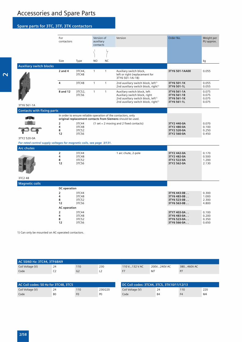
2
2/58
Accessories and Spare Parts
Spare parts for 3TC, 3TF, 3TK contactors
For Version of Version Order No. Weight percontactors auxiliary PU approx.
contacts
Size Type NO NC kg
Auxiliary switch blocks
2 and 4 3TC44, 1 1 Auxiliary switch block, 3TY6 501-1AA00 0.0553TC48 left or right (replacement for
3TY6 501-1A/-1B)
4 3TC48 1 1 2nd auxiliary switch block, left1) 3TY6 501-1K 0.0552nd auxiliary switch block, right1) 3TY6 501-1L 0.055
8 and 12 3TC52, 1 1 Auxiliary switch block, left 3TY6 561-1A 0.0753TC56 Auxiliary switch block, right 3TY6 561-1B 0.075
2nd auxiliary switch block, left1) 3TY6 561-1K 0.0752nd auxiliary switch block, right1) 3TY6 561-1L 0.075
3TY6 561-1A
Contacts with fixing parts
In order to ensure reliable operation of the contactors, onlyoriginal replacement contacts from Siemens should be used.
2 3TC44 (1 set = 2 moving and 2 fixed contacts) 3TY2 440-0A 0.0704 3TC48 3TY2 480-0A 0.1008 3TC52 3TY2 520-0A 0.25012 3TC56 3TY2 560-0A 0.450
3TY2 520-0A
For rated control supply voltages for magnetic coils, see page 3/131.
Arc chutes
2 3TC44 1 arc chute, 2-pole 3TY2 442-0A 0.1704 3TC48 3TY2 482-0A 0.5008 3TC52 3TY2 522-0A 1.20012 3TC56 3TY2 562-0A 2.130
3TC2 48
Magnetic coils
DC operation
2 3TC44 3TY6 443-0B . . 0.3004 3TC48 3TY6 483-0B . . 1.0008 3TC52 3TY6 523-0B . . 2.30012 3TC56 3TY6 563-0B . . 4.800
AC operation
2 3TC44 3TY7 403-0A . . 0.1004 3TC48 3TY6 483-0A . . 0.2008 3TC52 3TY6 523-0A . . 0.35012 3TC56 3TY6 566-0A . . 0.650
1) Can only be mounted on AC-operated contactors.
AC 50/60 Hz: 3TC44, 3TF68/69
Coil Voltage (V) 24 110 230 110 V...132 V AC 200V...240V AC 380...460V AC
Code C2 G2 L2 F7 M7 P7
AC Coil codes: 50 Hz for 3TC48, 3TC5
Coil Voltage (V) 24 110 230/220
Code B0 F0 P0
DC Coil codes: 3TC44, 3TC5, 3TK10/11/12/13
Coil Voltage (V) 24 110 220
Code B4 F4 M4

2
2/59
For Contacts Version Order No. Weight percontactors Version PU approx.
Size Type NO NC NC kg
Auxiliary switch blocks
With screw terminals
14 3TF68 1 1 — 1st auxiliary switch block, 3TY7 561-1AA00 0.050and left or right Replacement for:3TF69 3TY7 561-1A/ -1B.
1 — 1 Auxiliary switch block, 3TY7 561-1EA00 0.050left or right
1 1 — 2nd auxiliary switch block, 3TY7 561-1KA00 0.0503TY7 561-1 . A00 left or right Replacement for:
3TY7 561-1K/ -1L.
For coil reconnection with DC economy circuit, with screw terminals
14 3TF68 — — 1 Auxiliary switch block 3TY7 681-1G 0.050and3TF69
For Version Order No. Weight percontactors PU approx.
Size Type kg
Magnetic coils
AC operation
14 3TF68 The magnetic coils are fitted as standard with 3TY7 683-0C . . 1.3503TF69 varistors against overvoltage. The coil is supplied 3TY7 693-0C . . 1.700
with switch-on electronics.
DC operation · DC economy circuit
14 3TF68 Reversing contactors are required for 3TY7 683-0D . . 0.5603TF69 size 14 contactors: 3TY7 693-0D . . 0.560
Contactor type 3TF68 and 3TF69Reversing contactor 3TC44 (70 mm wide, 85 mm high)The magnetic coils are supplied without
3TY7 6 . 3-0 . . . reversing contactor.
Vacuum interrupters
In order to ensure reliable operation of the contactors, onlyoriginal replacement interrupters from Siemens should be used.
14 3TF68 3 vacuum interrupters with components 3TY7 680-0B 3.4903TF69 3TY7 690-0B 3.640
Accessories and Spare Parts
Spare parts for 3TC, 3TF, 3TK contactors

2
2/60
Accessories and Spare Parts
Spare parts for 3TC, 3TF, 3TK contactors
For contactor Version Rated control Order No. Weight persupply voltage Us PU approx.
Type V AC kg
Surge suppressors · RC elements
3TK10 to 3TK13 24 ... 48 3TK19 30-0A 0.050110 ... 415 3TK19 30-0B 0.050
3TK14 to 3TK17 48 ... 110 3TK19 34-0C 0.050220 ... 600 3TK19 34-0D 0.050
Terminal covers
3TK10, 3TK11 For mounting onto contactors 3TK19 40-0A 0.1503TK12, 3TK13 3TK19 42-0A 0.1503TK14, 3TK15 3TK19 44-0A 0.2003TK17 3TK19 46-0A 0.200
Auxiliary switch blocks
3TK1 1st auxiliary switch block, left or right 1 NO + 1 NC 3TK19 10-3A 0.0502nd auxiliary switch block,left or right 1 NO + 1 NC 3TK19 10-3B 0.050
Locking devices
3TK10, 3TK11 For mechanical interlocking of 2 identical 3TK19 20-0A 0.1403TK12, 3TK13 contactors, auxiliary contacts 2 NC 3TK19 22-0A 0.140
3TK14, 3TK15, 3TK17 Mechanical interlock,including mounting plate 3TK19 24-0A 6.750
Arc chutes
3TK10 1 arc chute, 4-pole 3TK19 50-0A 0.6503TK11 3TK19 51-0A 0.6503TK12 3TK19 52-0A 1.2503TK13 3TK19 53-0A 1.250
3TK14 3TK19 54-0A 3.7003TK15 3TK19 55-0A 3.7003TK17 3TK19 57-0A 3.700
Magnetic coils
3TK10, 3TK11 3TK19 70-0A . . 0.4003TK12, 3TK13 3TK19 72-0A . . 0.5003TK14, 3TK15, 3TK17 3TK19 74-0A . . 1.050
Contacts with fixing parts
3TK10 4 moving and 8 fixed contacts 3TK19 60-0A 0.2703TK11 3TK19 61-0A 0.2703TK12 3TK19 62-0A 0.5803TK13 3TK19 63-0A 0.580
3TK14 3TK19 64-0A 2.4003TK15 3TK19 65-0A 2.4003TK17 3TK19 67-0A 2.400

2a
2a/1
2aControls –Contactors andContactor Assemblies
2a/2 Introduction
3RT, 3TF Contactors for SwitchingMotors
2a/2 General data
2a/3 3RT10 contactors, 3-pole, 3 ... 250 kW
2a/36 3RT12 vacuum contactors, 3-pole, 110 ...250 kW
2a/44 3TF6 vacuum contactors, 3-pole, 335 ...450 kW
3RA13, 3RA14 Contactor Assemblies
3RA13 Reversing Contactor Assemblies
2a/49 3RA13 complete units, 3 ... 45 kW
3RA14 Contactor Assemblies for Wye-Delta Starting
2a/50 3RA14 complete units, 3 ...75 kW
3RT, 3RH, 3TC, 3TH, 3TK Contactors forSpecial Applications
3RT14 Contactors for Switching ResistiveLoads (AC-1)
2a/52 3-pole, 140 ... 690 A
3RT13 Contactors for Switching ResistiveLoads (AC-1)
2a/58 4-pole, 4 NO, 18 ... 140 A
3TK1 Contactors for Switching ResistiveLoads (AC-1)
2a/62 4-pole, 4 NO, 200 ... 1000 A
3RT15 Contactors
2a/64 4-pole, 2 NO + 2 NC, 4 ... 18.5 kW
3RT16 Capacitor Contactors
2a/66 12.5 ... 50 kvar
3TC Contactors for Switching DC Voltage
2a/68 1- and 2-pole, 32 ... 400 A
3RH, 3TH Contactor Relays
2a/71 3RH1 contactor relays, 4- and 8-pole
2a/74 3RH14 latched contactor relays, 4-pole
2a/75 3RH11 coupling relays for switchingauxiliary circuits, 4-pole
3RT Coupling Relays
2a/76 3RT10 coupling relays (interface), 3-pole,3 ... 11 kW
Accessories and Spare Parts
For 3RT, 3RH Contactors and ContactorRelays
2a/77 Accessories for 3RT, 3RH contactors andcontactor relays

2a
2a/2
3RT10 contactors, 3-pole, 3 ... 250 kW
3RT, 3TF Contactors for Switching Motors
Integration
Auxiliary switch blocks
Various auxiliary switch blocks can be added to the 3RT1 basicunits depending on the application:
Size S00
3RT10 1 . contactors
Size S00 contactors have an auxiliary contact integrated in thebasic unit.
All contactors of size S00 with one auxiliary contact(identification numbers 10E or 01) and the contactors with 4main contacts can be expanded into contactors with 3 or 5auxiliary contacts using auxiliary switch blocks with theidentification numbers 40 to 02 (in the case of contactors with4 main contacts: 2 or 4 auxiliary contacts) accordingto EN 50005.
The electronically-optimized 3RH19 11-1NF . . auxiliary switchblocks for contactors of size S00 include 2 enclosed contacts.They are suitable in particular for switching small voltages andcurrents (hard gold-plated contacts) and for operation in dustyatmospheres. The NC auxiliary contacts are not mirrorcontacts.
All the auxiliary switch variants can be snap-fitted onto thefront of the contactor. The auxiliary switch block has a centrallypositioned release lever for disassembly.
Sizes S0 to S3
3RT10 2 . to 3RT10 4 . contactors,1-pole auxiliary switch blocks,terminal designations according to EN 50005 or EN 50012.
The auxiliary switch variants are uniform for the contactorsof size S0 to S12.
One 4-pole or up to four single-pole auxiliary switch blocks canbe snapped on. When the contactors are switched on, the NCcontacts are opened first and then the NO contacts are closed.
The terminal designations of the single-pole auxiliary switchlocks are comprised of identification numbers (locationidentifiers) on the basic unit and of function numbers on theauxiliary switch blocks.
If the installation space is limited in depth, 2-pole auxiliaryswitch blocks can be attached laterally for use on the left or onthe right.
The auxiliary switch blocks attached to the front can bedisassembled with the help of a centrally arranged releaselever; the laterally attached auxiliary switch blocks are easy toremove by pressing on the checkered surfaces.
Sizes S0 and S2
A maximum of 4 auxiliary contacts can be attached; theauxiliary switch blocks used can be of any version. For reasonsof symmetry, when two 2-pole laterally mountable auxiliaryswitch blocks are used, one block must be attached on theright and one on the left.
More auxiliary contacts are permissible with size S2 under
certain conditions (please ask).
For 4-pole contactors see 3RT13 and 3RT15.
Size S3 to S12
A maximum of 8 auxiliary contacts can be attached; pleasenote the following:
• Of these 8 auxiliary contacts, there must be no more than 4NC contacts
• Ensure the symmetry of laterally mounted auxiliary switchblocks
For 4-pole contactors see 3RT13 and 3RT15.

2a
2a/3
3RT10 contactors, 3-pole, 3 ... 250 kW
3RT, 3TF Contactors for Switching Motors
�
� �� �
� � � � �� � �
� � � � �� � �
� � � � �� � �
� � � �
� � � � �
� �
� � � � � � � � � � �
�
�
���
�
�
� �
� �
� �
� � � � � � � � � � � � � � � � � � � � � � � � �
� � � � � �� � �
� � � � � �� � �
� � � � � �� � � �
� � � � � �� � �
� � � � � � � � �
� � � � � � � � � � � ! � � " # $ % & � ' � � � ( ( � ) & �
*�%%�&�&(�+����,�-�%�����
�
Technical specifications
SIRIUS controls are climate-proof and are suitable and testedfor use worldwide.
If the devices are used in ambient conditions which deviate fromcommon industrial conditions (EN 60721-3-3 “Stationary Use,
Weather-Protected”), the manufacturer must be consulted aboutpossible restrictions with regard to the reliability and enduranceof the device and possible protective measures.
Contactor Type 3RT1 Size S00 ... S12
Rated data of the auxiliary contacts
Acc. to IEC 60947-5-1/EN 60947-5-1 (VDE 0660 Part 200)The data apply to integrated auxiliary contacts and contacts in theauxiliary switch blocks for contactor sizes S00 to S121)
Rated insulation voltage Ui (degree of pollution 3) V 690
For 3RH19 21-. laterally mountable auxiliary switch blocks V Max. 500
Continuous thermal current Ith
= A 10Rated operational current I
e/AC-12
AC load
Rated operational current Ie/AC-15/AC-14
for rated operational voltage Ue
24 V A 6110 V A 6125 V A 6220 V A 6230 V A 6
380 V A 3415 V A 3500 V A 2
660 V2) A 1690 V2) A 1
DC load
Rated operational current Ie/DC-12
for rated operational voltage Ue 24 V A 1060 V A 6
110 V A 3125 V A 2
220 V A 1440 V A 0.3
600 V2) A 0.15
Rated operational current Ie/DC-13
for rated operational voltage Ue 24 V A 101)
60 V A 2110 V A 1125 V A 0.9
220 V A 0.3440 V A 0,14
600 V2) A 0,1
• Contact reliability at 17 V, 1 mA Frequency of contact faults < 10-8 i.e. <1 fault per 100 million operatingacc. to EN 60947-5-4 cycles
Endurance of the auxiliary contacts
It is assumed that the operating mechanisms are switched randomly, i.e.not synchronized with the phase angle of the supply system.The contact endurance is mainly dependent on the breaking current.The characteristic curves apply to• Integrated auxiliary contacts for 3RT10• 3RH19 11, 3RH19 21 auxiliary switch blocks for contactorsizes S00 to S12.
Legend:Ia = Breaking current
Ie = Rated operational current
1) Attachable auxiliary switch blocks for size S00 and laterally mountableauxiliary switch blocks for S0 to S12: 6 A.
2) Up to 500 V switching capacity for laterally mountable auxiliary switchblocks.

2a
2a/4
3RT10 contactors, 3-pole, 3 ... 250 kW
3RT, 3TF Contactors for Switching Motors
Endurance of the main contacts
The characteristic curves show the contact endurance of thecontactors when switching resistive and inductive AC loads(AC-1/AC-3) depending on the breaking current and ratedoperational voltage. It is assumed that the operatingmechanisms are switched randomly, i.e. not synchronized withthe phase angle of the supply system.
The rated operational current Ie complies with utilization
category AC-4 (breaking six times the rated operationalcurrent) and is intended for a contact endurance of at least200 000 operating cycles.
If a shorter endurance is sufficient, the rated operationalcurrent I
e/AC-4 can be increased.
If the contacts are used for mixed operation, i.e. normalswitching (breaking the rated operational current according toutilization category AC-3) in combination with intermittentinching (breaking several times the rated operational currentaccording to utilization category AC-4), the contact endurancecan be calculated approximately from the following equation:
Characters in the equation:
X Contact endurance for mixed operation in operating cycles
A Contact endurance for normal operation (Ia = I
e) in operating
cycles
B Contact endurance for inching (Ia = multiple of I
e) in
operating cycles
C Inching operations as a percentage of total switchingoperations
Diagram legend:
PN= Rated power for squirrel-cage motors at 415 V
Ia= Breaking current
Ie= Rated operational current
Size S00
Size S0
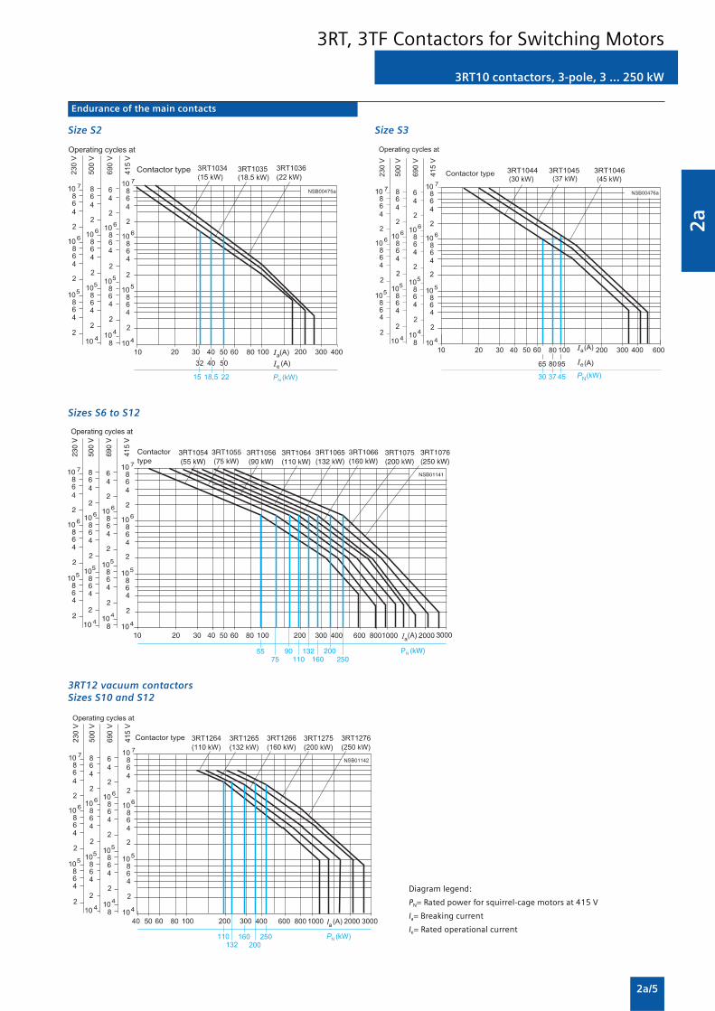
2a
2a/5
3RT10 contactors, 3-pole, 3 ... 250 kW
3RT, 3TF Contactors for Switching Motors
Endurance of the main contacts
Size S2
Sizes S6 to S12
3RT12 vacuum contactorsSizes S10 and S12
Size S3
Diagram legend:
PN= Rated power for squirrel-cage motors at 415 V
Ia= Breaking current
Ie= Rated operational current

2a
2a/6
3RT10 contactors, 3-pole, 3 ... 250 kW
3RT, 3TF Contactors for Switching Motors
��.��/�� � � � 0 � � � � 0� � 0
Contactor Type 3RT10 1 . Size S00
General data
Permissible mounting position AC and DC operationThe contactors are designed foroperation on a vertical mountingsurface.
Mechanical endurance Basic unit Opera- 30 milliontingcycles
Basic unit with snap-onauxiliary switch block 10 million
Electrical endurance 1)
Rated insulation voltage Ui (degree of pollution 3) V 690
Rated impulse withstand voltage Uimp
kV 6
Safe isolation between the coil and the main contacts V 400/415acc. to EN 60947-1, Appendix N
Mirror contacts• A mirror contact is an auxiliary 3RT10 1 ., 3RT13 1 . Yes, this applies to both the basic unit as well as to between the basic unit
NC contact that cannot be (removable auxiliary and the mounted auxiliary switch block acc. to EN 60947-4-1,closed simultaneously with a switch block) Appendix F.NO main contact.
Ambient temperature During operation °C -25 ... +60During storage °C -55 ... +80
Degree of protection acc. to EN 60947-1, Appendix C IP20, coil assembly IP40Touch protection acc. to EN 50274 Finger-safe
Shock resistance AC operation g/ms 7/5 and 4.2/10rectangular pulse DC operation g/ms 7/5 and 4.2/10
Shock resistance sine pulse AC operation g/ms 9.8/5 and 5.9/10DC operation g/ms 9.8/5 and 5.9/10
Conductor cross-sections 2)
Short-circuit protection for contactors without overload relays
For short-circuit protection for contactors with overload relays seeProtection Equipment: Overload RelaysFor short-circuit protection for fuseless load feeders see Load Feeders,Motor Starters and Soft Starters: -> 3RA Fuseless Load Feeders.
Main circuit
• Fuse links gL/gG LV HRC 3NA, DIAZED 5SB, NEOZED 5SE- Acc. to IEC 60947-4-1/ Type of coordination “1” A 35
EN 60947-4-1 Type of coordination “2” A 20 Weld-free3) A 10
• Miniature circuit breakers (up to 230 V) with C characteristic A 10Short-circuit current 1 kA, type of coordination “1”
Auxiliary circuit
• Fuse links gL/gGDIAZED 5SB, NEOZED 5SE (weld-free protection I
k ≥ 1 kA) A 10
• Miniature circuit breakers up to 230 V with C characteristic A 6Short-circuit current I
k < 400 A
Control
Magnetic coil operating range
• AC operation 50 Hz 0.8 ... 1.1 x Us
60 Hz 0.85 ... 1.1 x Us
• DC operation up to 50 °C 0.8 ... 1.1 x Us
up to 60 °C 0.85 ... 1.1 x Us
Power consumption of the magnetic coils (when coil is cold and 1.0 x Us)
AC operation, 50/60 Hz
Standard version • Closing VA 27/24.3• P.f. 0.8/0.75• Closed VA 4.4/3.4• P.f. 0.27/0.27
DC operation Closing = Closed W 3.3
1) For endurance of the main contacts see page 2a/4.
2) For conductor cross-sections see page 2a/9.
3) Test conditions according to IEC 60947-4-1.

2a
2a/7
3RT10 contactors, 3-pole, 3 ... 250 kW
3RT, 3TF Contactors for Switching Motors
1) The OFF-delay of the NO contact and the ON-delay of the NC contact areincreased if the contactor coils are attenuated against voltage peaks(noise suppression diode 6 to 10 times; diode assemblies 2 to 6 times,varistor +2 to 5 ms).
1) Industrial furnaces and electric heaters with resistance heating, etc.(increased power consumption on heating up has been taken intoaccount).
2) According to IEC 60947-4-1. For rated values for various start-upconditions see Protection Equipment: Overload Relays.
3) The data only apply to 3RT15 16 and 3RT15 17 (2NO + 2NC) upto a ratedoperational voltage of 400/415V
Contactor Type 3RT10 1 . Size S00
Control
Operating times1)
Total break time = Opening delay + Arcing time
• AC operation Closing delay ms 8 ... 35at 0.8 ... 1.1 x Us Opening delay ms 4 ... 30
• DC operation Closing delay ms 25 ... 100at 0.85 ... 1.1 x U
sOpening delay ms 7 ... 10
• Arcing time ms 10 ... 15
Operating times for 1.0 x Us1)
• AC operation Closing delay ms 10 ... 25Opening delay ms 5 ... 30
• DC operation Closing delay ms 30 ... 50Opening delay ms 7 ... 9
Contactor Type 3RT10 15 3RT10 16 3RT10 17 Size S00 S00 S00
Main circuit
AC capacity
Utilization category AC-1Switching resistive loads
Rated operational current Ie at 40 °C up to 690 V A 18 22 22 at 60 °C up to 690 V A 16 20 20
Rated power for AC loads1) 400/415 V kW 11 13 13P.f.= 0.95 (at 60 °C)
Minimum conductor cross-section at 40/60 °C mm2 2.5 2.5 2.5for loads with I
e
Utilization categories AC-2 and AC-3
Rated operational currents Ie up to 415 V A 7 9 12 500 V A 5 6.5 9 690 V A 4 5.2 6.3
Rated power for slipring or squirrel-cage at 230 V kW 2.2 3 3motors at 50 and 60 Hz 415 V kW 3 4 5.5
500 V kW 3.5 4.5 5.5690 V kW 4 5.5 5.5
Thermal load capacity 10 s current2) A 56 72 96
Power loss per conducting path at Ie/AC-3 W 0.42 0.7 1.24
Utilization category AC-4 (for Ia = 6 x I
e)3)
Rated operational current Ie up to 415 V A 6.5 8.5 8.5
Rated power for squirrel-cage motors up to 415 V kW 3 4 4with 50 Hz and 60 Hz
• The following applies to a contact endurance ofabout 200000 operating cycles:
- rated operational currents Ie
up to 415 V A 2.6 4.1 4.1690 V A 1.8 3.3 3.3
- rated power for squirrel-cage motors at 230 V kW 0.67 1.1 1.1with 50 Hz and 60 Hz 415 V kW 1.15 2 2
500 V kW 1.45 2 2690 V kW 1.15 2.5 2.5

2a
2a/8
3RT10 contactors, 3-pole, 3 ... 250 kW
3RT, 3TF Contactors for Switching Motors
1) Depending on the electronic ballast used, higher lamp numbers are alsopossible.
Contactor Type 3RT10 15 3RT10 16 3RT10 17 Size S00 S00 S00
Main circuit
AC capacity
Utilization category AC-5aSwitching gas discharge lamps, inductive ballastPer main current path at 230 V
• Uncorrected,rated power per lamp/rated operational current per lamp
L 18 W/0.37 A Units 54 59 59 L 36 W/0.43 A Units 46 51 51 L 58 W/0.67 A Units 29 32 32
L 80 W/0.79 A Units 25 27 27
• DUO switching (two-lamp)
L 18 W/0.22 A Units 90 ( 2 x 90 lamps) 100 ( 2 x 100 lamps) 100 ( 2 x 100 lamps) L 36 W/0.42 A Units 47 ( 2 x 47 lamps) 52 ( 2 x 52 lamps) 52 ( 2 x 52 lamps) L 58 W/0.63 A Units 31 ( 2 x 31 lamps) 34 ( 2 x 34 lamps) 34 ( 2 x 34 lamps)
L 80 W/0.87 A Units 22 ( 2 x 22 lamps) 25 ( 2 x 25 lamps) 25 ( 2 x 25 lamps)
Switching gas discharge lamps with correctionPer main current path at 230 V
• Shunt compensation with inductive ballast,rated power per lamp/capacitance/rated operational current per lamp
L 18 W/4.5 μF/0.11 A Units 17 22 22 L 36 W/4.5 μF/0.21 A Units 16 22 22 L 58 W/7.0 μF/0.32 A Units 10 14 14
L 80 W/7.0 μF/0.49 A Units 6 9 9
• With solid-state ballast1) single lamp
L 18 W/6.8 μF/0.10 A Units 49 63 63 L 36 W/6.8 μF/0.18 A Units 27 35 35 L 58 W/10 μF/0.29 A Units 16 23 23
L 80 W/10 μF/0.43 A Units 11 14 14
• With solid-state ballast1) two-lamp
L 18 W/10 μF/0.18 A Units 27 ( 2 x 27 lamps) 35 ( 2 x 35 lamps) 35 ( 2 x 35 lamps) L 36 W/10 μF/0.35 A Units 14 ( 2 x 14 lamps) 18 ( 2 x 18 lamps) 18 ( 2 x 18 lamps) L 58 W/22 μF/0.52 A Units 9 ( 2 x 9 lamps) 12 ( 2 x 12 lamps) 12 ( 2 x 12 lamps)
L 80 W/22 μF/0.86 A Units 5 ( 2 x 5 lamps) 7 ( 2 x 7 lamps) 7 ( 2 x 7 lamps)
Utilization category AC-5b, switching incandescent lamps kW 1.3 1.7 1.7Per main current path at 230/220 V
Utilization category AC-6aswitching AC transformers
Rated operational current Ie
• For inrush current n = 20 up to 415 V A 3.6 5.1 7.2• For inrush current n = 30 up to 415 V A 2.4 3.3 5.1
Rated power P
• For inrush current n = 20 at 400/415 V kVA 2.5 3.5 5
• For inrush current n = 30 at 400/415 V kVA 1.6 2.3 3.5
For deviating inrush current factors x, the power mustbe recalculated as follows:P
x = P
n 30 · 30/x
DC capacity
Utilization category DC-1Switching resistive loads (L/R £ 1ms)Rated operational current I
e (at 60 °C)
• 1 conducting path up to 24 V A 15 20 110 V A 1.5 2.1
220 V A 0.6 0.8 440 V A 0.42 0.6
• 2 conducting paths in series up to 24 V A 15 20 110 V A 8.4 12
220 V A 1.2 1.6 440 V A 1.6 0.8
• 3 conducting paths in series up to 24 V A 15 20 110 V A 15 20
220 V A 15 20 440 V A 0.9 1.3

2a
2a/9
3RT10 contactors, 3-pole, 3 ... 250 kW
3RT, 3TF Contactors for Switching Motors
Contactor Type 3RT10 15 3RT10 16 3RT10 17 Size S00 S00 S00
Main circuit
DC capacity
Utilization category DC-3 and DC-5Shunt-wound and series-wound motors (L/R ≤ 15 ms)Rated operational current Ie (at 60 °C)
• 1 conducting path up to 24 V A 15 20 110 V A 0.1 0.15
220 V A — — 440 V A — —
• 2 conducting paths in series up to 24 V A 15 20 110 V A 0.25 0.35
220 V A — — 440 V A — —
• 3 conducting paths in series up to 24 V A 15 20 110 V A 15 20
220 V A 1.2 1.5 440 V A 0.14 0.2
Switching frequency
Switching frequency z in operating cycles/hour
• Contactors without overload relay No-load switching frequency AC h-1 10000No-load switching frequency DC h-1 10000
Dependence of the switching Rated operationfrequency z’ on the operational AC-1 (AC/DC) h-1 1000current I’ and operational voltage U’: AC-2 (AC/DC) h-1 750z’ = z ·(Ie/I’) ·(400 V/U’)1.5 ·1/h AC-3 (AC/DC) h-1 750
AC-4 (AC/DC) h-1 250
• Contactors with overload relays (mean value) h-1 15
Conductor cross-sections
• Screw terminals Main and auxiliary conductors: Screw terminals
(1 or 2 conductors can be • Solid mm2 2 x (0.5 ... 1.5)1); 2 x (0.75 ... 2.5)1) acc. to IEC 60947; max. 2 x (1 ... 4)connected) • Finely stranded with end sleeve mm2 2 x (0.5 ... 1.5)1); 2 x (0.75 ... 2.5)1)
For standard screwdriver • Solid or stranded, AWG 2 x (20 ... 16)1); 2 x (18 ... 14)1); 1 x 12size 2 and Pozidriv 2 AWG cables
• Terminal screw M3- tightening torque Nm 0.8 ... 1.2 (7 ... 10.3 lb.in)
1) If two different conductor cross-sections are connected to one clampingpoint, both cross-sections must lie in the range specified.If identical cross-sections are used, this restriction does not apply.

2a
2a/10
3RT10 contactors, 3-pole, 3 ... 250 kW
3RT, 3TF Contactors for Switching Motors
��.��/�� � � � 0 � � � � 0� � 0
Contactor Type 3RT10 23 3RT10 24 3RT10 25 3RT10 26Size S0 S0 S0 S0
General data
Permissible mounting position AC and DC operationThe contactors are designed foroperation on a vertical mountingsurface.
Mechanical endurance Basic unit Opera- 10 milliontingcycles
Basic unit with snap-on 10 millionauxiliary switch block
Electrical endurance 1)
Rated insulation voltage Ui (degree of pollution 3) V 690
Rated impulse withstand voltage Uimp
kV 6
Safe isolation between the coil and the main contacts V 400(acc. to EN 60947-1, Appendix N)
Mirror contacts• A mirror contact is an auxiliary 3RT10 2 . , 3RT13 2 . Yes, acc. to EN 60947-4-1, Appendix F
NC contact that cannot be (removable auxiliary switch block)closed simultaneously with aNO main contact.
Permissible ambient temperature During operation °C -25 ... +60During storage °C -55 ... +80
Degree of protection acc. to EN 60947-1, Appendix C IP20, coil assembly IP20Touch protection acc. to EN 50274 Finger-safe
Shock resistance rectangular pulse AC operation g/ms 8.2/5 and 4.9/10DC operation g/ms 10/5 and 7.5/10
Shock resistance sine pulse AC operation g/ms 12.5/5 and 7.8/10DC operation g/ms 15/5 and 10/10
Conductor cross-sections 2)
Short-circuit protection for contactors without overload relays
Main circuit For short-circuit protection for contactors with overload relays seeProtection Equipment: Overload Relays
• Fuse links gL/gG For short-circuit protection for fuseless load feeders see Load Feeders,LV HRC 3NA, DIAZED 5SB, NEOZED 5SE Motor Starters and Soft Starters: -> 3RA Fuseless Load Feeders.- acc. to IEC 60947-4-1/ Type of coordination “1” A 63 100
EN 60947-4-1 Type of coordination “2” A 25 35Weld-free3) A 10 16
• Miniature circuit breakers with C characteristic A 25 32(short-circuit current 3 kA, type of coordination “1”)
Auxiliary circuit
• Fuse links gL/gG A 10DIAZED 5SB, NEOZED 5SE(weld-free protection at Ik ≥ 1 kA)
• Miniature circuit breaker with C characteristic A 10(short-circuit current I
k < 400 A)
1) For endurance of the main contacts see page 2a/4.
2) For conductor cross-sections see page 2a/13.
3) Test conditions according to IEC 60947-4-1.
Contactor Type 3RT10 2 . Size S0
Control
Magnetic coil operating range AC/DC 0.8 ... 1.1 x Us
Power consumption of the magnetic coils (when coil is cold and 1.0 x Us)
AC operation, 50 Hz, • Closing VA 61standard version • P.f. 0.82
• Closed VA 7.8• P.f. 0.24
AC operation, 50/60 Hz, • Closing VA 64/63standard version • P.f. 0.72/0.74
• Closed VA 8.4/6.8• P.f. 0.24/0.28
DC operation Closing = Closed W 5.4

2a
2a/11
3RT10 contactors, 3-pole, 3 ... 250 kW
3RT, 3TF Contactors for Switching Motors
Contactor Type 3RT10 2 . Size S0
Control
Operating times for 0.8 ... 1.1 x Us1)
Total break time = Opening delay + Arcing time
• AC operation Closing delay ms 8 ... 44Opening delay ms 4 ... 20
• DC operation Closing delay ms 50 ... 170Opening delay ms 13.5 ... 15.5
• Arcing time ms 10
Operating times for 1.0 x Us1)
• AC operation Closing delay ms 10 ... 17Opening delay ms 4 ... 20
• DC operation Closing delay ms 55 ... 85Opening delay ms 14 ... 15.5
1) The OFF-delay of the NO contact and the ON-delay of the NC contact areincreased if the contactor coils are attenuated against voltage peaks(varistor +2 ms to 5 ms, diode assembly: 2 to 6 times).
Contactor Type 3RT10 23 3RT10 24 3RT10 25 3RT10 26 Size S0 S0 S0 S0
Main circuit
AC capacity
Utilization category AC-1Switching resistive loads
Rated operational current Ie
at 40 °C up to 690 V A 40 at 60 °C up to 690 V A 35
Rated power for AC loads1) 415 V kW 23P.f. = 0.95 (at 60 °C)
Minimum conductor cross-section for at 40/60 °C mm2 10loads with I
e
Utilization category AC-2 and AC-3
Rated operational currents Ie
up to 415 V A 9 12 17 25440 V A 9 12 17 22500 V A 6.5 12 17 18690 V A 5.2 9 13 13
Rated power for slipring or squirrel- at 110 V kW 1.1 1.5 2.2 3cage motors at 50 Hz and 60 Hz 230 V kW 3 3 4 5.5
415 V kW 4 5.5 7.5 11500 V kW 4.5 7.5 10 11
660 V / 690 V kW 5.5 7.5 11 11
Thermal load capacity 10 s current2) A 80 110 150 200
Power loss per conducting path at Ie/AC-3 W 0.4 0.5 0.9 1.6
Utilization category AC-4 (for Ia = 6 x I
e)
Rated operational current Ie
up to 415 V A 8.5 12.5 15.5 15.5
Rated power for squirrel-cage motors with at 415 V kW 4 5.5 7.5 7.550 Hz and 60 Hz
• The following applies to a contact endurance of about200000 operating cycles:
Rated operational currents Ie
up to 415 V A 4.1 5.5 7.7 9690 V A 3.3 5.5 7.7 9
Rated power for squirrel-cage motors with at 110 V kW 0.5 0.73 1 1.250 Hz and 60 Hz 230 V kW 1.1 1.5 2 2.5
415 V kW 2 2.6 3.5 4.4500 V kW 2 3.3 4.6 5.6690 V kW 2.5 4.6 6 7.7
1) Industrial furnaces and electric heaters with resistance heating, etc.(increased power consumption on heating up has been taken intoaccount).
2) According to IEC 60947-4-1.For rated values for various start-up conditionssee Protection Equipment: Overload Relays.

2a
2a/12
3RT10 contactors, 3-pole, 3 ... 250 kW
3RT, 3TF Contactors for Switching Motors
Contactor Type 3RT10 23 3RT10 24 3RT10 25 3RT10 26 Size S0 S0 S0 S0
Main circuit
AC capacity
Utilization category AC-5aSwitching gas discharge lamps, inductive ballastPer main current path at 230 V1)
Rated power per lamp/rated operational current per lamp
Uncorrected L 18 W/0.37 A Units 108L 36 W/0.43 A Units 93L 58 W/0.67 A Units 59L 80 W/0.79 A Units 50
DUO switching (two-lamp) L 18 W/0.22 A Units 181 ( 2 x 181 lamps)L 36 W/0.42 A Units 95 ( 2 x 95 lamps)L 58 W/0.63 A Units 63 ( 2 x 63 lamps)L 80 W/0.87 A Units 45 ( 2 x 45 lamps)
Switching gas discharge lamps with correctionPer main current path at 230 V
Rated power per lamp/capacitance/rated operational current per lamp
• Shunt compensation with inductive L 18 W/4.5 μF/0.11 A Units 37 41 61ballast L 36 W/4.5 μF/0.21 A Units 30 30 51
L 58 W/7.0 μF/0.32 A Units 20 20 33L 80 W/7.0 μF/0.49 A Units 13 13 22
• With solid-state ballast2) single lamp L 18 W/6.8 μF/0.10 A Units 105 119 175 L 36 W/6.8 μF/0.18 A Units 58 66 97
L 58 W/10 μF/0.29 A Units 36 41 60L 80 W/10 μF/0.43 A Units 24 27 40
• With solid-state ballast2) two-lamp L 18 W/10 μF/0.18 A Units 58 ( 2 x 58 lamps) 66 ( 2 x 66 l.) 97 ( 2 x 97 l.) L 36 W/10 μF/0.35 A Units 30 ( 2 x 30 lamps) 34 ( 2 x 34 l.) 50 ( 2 x 50 l.)
L 58 W/22 μF/0.52 A Units 20 ( 2 x 20 lamps) 22 ( 2 x 22 l.) 33 ( 2 x 33 l.)L 80 W/22 μF/0.86 A Units 12 ( 2 x 12 lamps) 13 ( 2 x 13 l.) 20 ( 2 x 20 l.)
Utilization category AC-5b, switching incandescent lamps kW 2.8 3.2 4.7Per main current path at 230/220 V
Utilization category AC-6aswitching AC transformers
Rated operational current Ie
• For inrush current n = 20 up to 415 V A 11.4 20.2• For inrush current n = 30 up to 415 V A 7.6 13.5
Rating P
• For inrush current n = 20 415 V kVA 7.9 13.9• For inrush current n = 30 415 V kVA 5.2 9.3
For deviating inrush current factors x, the power must be recalculated as follows:P
x = P
n30 · 30/x
Utilization category AC-6b,switching low-inductance (low-loss, metallized dielectric) AC capacitors
Rated operational currents Ie up to 415 V A 5.8 10.8
Rated power for single capacitors or at 230 V kvar 2.5 4banks of capacitors (minimum inductance 400 V kvar 4 7.5of 6 μH between capacitors connected 500 V kvar 4 7.5in parallel) at 50 Hz, 60 Hz and 690 V kvar 4 7.5
DC capacity
Utilization category DC-1Switching resistive loads (L/R ≤≤≤≤≤ 1ms)
Rated operational current Ie (at 60 °C)
• 1 conducting path up to 24 V A 35110 V A 4.5
220 V A 1440 V A 0.4
• 2 conducting paths in series up to 24 V A 35110 V A 35
220 V A 5440 V A 1
• 3 conducting paths in series up to 24 V A 35110 V A 35
220 V A 35440 V A 2.9
1) For Ie/AC-1 = 35 A (60 °C) and the corresponding minimum conductorcross-section 10 mm2.
2) Depending on the electronic ballast used, higher lamp numbers are alsopossible.

2a
2a/13
3RT10 contactors, 3-pole, 3 ... 250 kW
3RT, 3TF Contactors for Switching Motors
Contactor Type 3RT10 23 3RT10 24 3RT10 25 3RT10 26 Size S0 S0 S0 S0
Main circuit
Utilization category DC-3 and DC-5Shunt-wound and series-wound motors (L/R ≤≤≤≤≤ 15 ms)Rated operational current I
e (at 60 °C)
• 1 conducting path up to 24 V A 20110 V A 2.5
220 V A 1440 V A 0.09
• 2 conducting paths in series up to 24 V A 35110 V A 15
220 V A 3440 V A 0.27
• 3 conducting paths in series up to 24 V A 35110 V A 35
220 V A 10440 V A 0.6
Switching frequency
Switching frequency z in operating cycles/hour
• Contactors without overload relays No-load switching h-1 5000frequency AC
Dependence of the switching frequency z’ No-load switching h-1 1500on the operational current I’ and operational frequency DCvoltage U’:z’ = z ·(Ie/I’) ·(400 V/U’)1.5 ·1/h AC-1 (AC/DC) h-1 1000
AC-2 (AC/DC) h-1 1000 750AC-3 (AC/DC) h-1 1000 750AC-4 (AC/DC) h-1 300 250
• Contactors with overload relays (mean value) h-1 15
Conductor cross-sections
Screw terminals Main conductors Screw terminals
(1 or 2 conductors can be Conductor cross-sectionconnected) • Solid mm² 2 x (1 ... 2.5)1); 2 x (2.5 ... 6)1) acc. to IEC 60947; max. 1 x 10
• Finely stranded with end sleeve mm² 2 x (1 ... 2.5)1); 2 x (2.5 ... 6)1)
• AWG cables, solid AWG 2 x (16 ... 12)• AWG cables, AWG 2 x (14 ... 10)
solid or stranded• AWG cables, stranded AWG 1 x 8• Terminal screws M4 (Pozidriv size 2)
- tightening torque Nm 2 ... 2.5 (18 ... 22 lb.in)
Auxiliary conductors
Conductor cross-section • Solid mm2 2 x (0.5 ... 1.5)1); 2 x (0.75 ... 2.5)1) 0.75) acc. to IEC 60947;
max. 2 x (0.75 ... 4)• Finely stranded with end sleeve mm2 2 x (0.5 ... 1.5)1); 2 x (0.75 ... 2.5)1)
• Solid or stranded AWG (2 x) AWG 2 x (20 ... 16)1); 2 x (18 ... 14)1); 1 x 12• Terminal screws M3
- tightening torque Nm 0.8 ... 1.2 (7 ... 10.3 lb.in)

2a
2a/14
3RT10 contactors, 3-pole, 3 ... 250 kW
3RT, 3TF Contactors for Switching Motors
��.��/�� � � � 0 � � � � 0� � 0
Contactor Type 3RT10 34 3RT10 35 3RT10 36 Size S2 S2 S2
General data
Permissible mounting position AC and DC operationThe contactors are designed foroperation on a vertical mountingsurface.
For DC operation and 22.5 ° inclination towards the front,operating range 0.85 ... 1.1 x Us
Mechanical endurance Basic units Opera- 10 milliontingcycles
Basic unit with snap-on auxiliary 10 millionswitch block
Electrical endurance 1)
Rated insulation voltage Ui (degree of pollution 3) V 690Rated impulse withstand voltage Uimp kV 6Safe isolation between the coil and the main contacts V 415acc. to EN 60947-1, Appendix NMirror contactsA mirror contact is an auxiliary 3RT10 3 . , 3RT13 3 . Yes, acc. to EN 60947-4-1, Appendix FNC contact that cannot be (removable auxiliary switch block)closed simultaneously with aNO main contact.Permissible ambient temperature During operation °C -25 ... +60
During storage °C -55 ... +80Degree of protection acc. to EN 60947-1, Appendix C IP20 (terminal compartment IP00),
AC coil assembly IP40,DC coil assembly IP30
Touch protection acc. to EN 50274 finger-safeShock resistance• Rectangular pulse AC and DC operation g/ms 10/5 and 5/10• Sine pulse AC and DC operation g/ms 15/5 and 8/10Conductor cross-sections 2)
Short-circuit protection for contactors without overload relays For short-circuit protection for contactors with overload relays see
Protection Equipment: Overload RelaysFor short-circuit protection for fuseless load feeders see Load Feeders,Motor Starters and Soft Starters: -> 3RA Fuseless Load Feeders.
Main circuitFuse links, gL/gGLV HRC 3NA, DIAZED 5SB, NEOZED 5SE Acc. to IEC 60947-4-1/ Type of coordination “1” A 125 125 160EN 60947-4-1 Type of coordination “2” A 63 63 80
Weld-free3) A 16 16 50Auxiliary circuit • Fuse links gL/gG A 10
DIAZED 5SB, NEOZED 5SE (weld-free protection at Ik ≥ 1 kA)• Miniature circuit breakers with C characteristic A 10
(short-circuit current Ik ≤ 400 A)
Control
Magnetic coil operating range AC/DC 0.8 ... 1.1 x Us
Power consumption of the magnetic coils (when coil is cold and 1.0 x Us) AC operation, 50 Hz, • Closing VA 104 145standard version • P.f. 0.78 0.79
• Closed VA 9.7 12.5• P.f. 0.42 0.36
AC operation, 50/60 Hz, • Closing VA 127/113 170/155standard version • P.f. 0.73/0.69 0.76/0.72
• Closed VA 11.3/9.5 15/11.8• P.f. 0.41/0.42 0.35/0.38
DC operation Closing = Closed W 13.3 13.3Operating times for 0.8 ... 1.1 x Us
4) (Total break time = Opening delay + Arcing time)AC operation • Closing delay ms 11 ... 30 10 ... 24
• Opening delay ms 7 ... 10 7 ... 10DC operation • Closing delay ms 50 ... 95 60 ... 100
• Opening delay ms 20 ... 30 20 ... 25Arcing time ms 10 10Operating times for 1.0 x Us
4) AC operation • Closing delay ms 13 ... 22 12 ... 20
• Opening delay ms 7 ... 10 7 ... 10DC operation • Closing delay ms 60 ... 75 70 ... 85
• Opening delay ms 20 ... 30 20 ... 25
1) For endurance of the main contacts see page 2a/5.2) For conductor cross-sections see page 2a/17.3) Test conditions according to IEC 60947-4-1.
4) The OFF-delay of the NO contact and the ON-delay of the NC contact areincreased if the contactor coils are attenuated against voltage peaks(varistor +2 ms to 5 ms, diode assembly: 2 to 6 times).

2a
2a/15
3RT10 contactors, 3-pole, 3 ... 250 kW
3RT, 3TF Contactors for Switching Motors
Contactor Type 3RT10 34 3RT10 35 3RT10 36 Size S2 S2 S2
Main circuit
AC capacity
Utilization category AC-1Switching resistive loads
Rated operational currents Ie at 40 °C up to 690 V A 50 60 60 at 60 °C up to 690 V A 45 55 55
Rated power for AC loads1) 415 V kW 31 38 38P.f. = 0.95 (at 60 °C)
Minimum conductor cross-section for at 40 °C mm2 16 16 16loads with Ie at 60 °C mm2 10 16 16
Utilization category AC-2 and AC-3
Rated operational currents Ie up to 500 V A 32 40 50 690 V A 20 24 24
Rated power for slipring 230 V kW 7.5 11 15or squirrel-cage motors 415 V kW 15 18.5 22at 50 and 60 Hz 500 V kW 18.5 22 30
690 V kW 18.5 22 22
Thermal load capacity 10 s current2) A 320 400 400
Power loss per conducting path at Ie/AC-3 W 1.8 2.6 5
Utilization category AC-4 (for Ia = 6 x Ie)
Rated operational current Ie up to 415 V A 29 35 41
Rated power for squirrel-cage motors at 415 V kW 15 18.5 22with 50 Hz and 60 Hz
• The following applies to a contact endurance of about200000 operating cycles:
Rated operational currents Ie up to 415 V A 15.6 18.5 24690 V A 15.6 18.5 24
Rated power for squirrel-cage motors 230 V kW 4.7 5.4 7.3with 50 Hz and 60 Hz 415 V kW 8.2 9.5 12.6
500 V kW 9.8 11.8 15.8690 V kW 13 15.5 21.8
Utilization category AC-5aSwitching gas discharge lamps, inductive ballastPer main current path at 230 V
• Uncorrected,rated power per lamp/rated operational current per lamp
L 18 W/0.37 A Units 135 162 162 L 36 W/0.43 A Units 116 139 139 L 58 W/0.67 A Units 74 89 89
L 80 W/0.79 A Units 63 75 75
• DUO switching (two-lamp) L 18 W/0.22 A Units 227 ( 2 x 227 lamps) 272 ( 2 x 272 lamps) 272 ( 2 x 272 lamps) L 36 W/0.42 A Units 119 ( 2 x 119 lamps) 142 ( 2 x 142 lamps) 142 ( 2 x 142 lamps)
L 58 W/0.63 A Units 79 ( 2 x 79 lamps) 95 ( 2 x 95 lamps) 95 ( 2 x 95 lamps)L 80 W/0.87 A Units 57 ( 2 x 57 lamps) 68 ( 2 x 68 lamps) 68 ( 2 x 68 lamps)
Switching gas discharge lamps with correctionPer main current path at 230 V
• Shunt compensation with inductive ballast,rated power per lamp/capacitance/rated operational current per lamp
L 18 W/4.5 μF/0.11 A Units 78 98 123 L 36 W/4.5 μF/0.21 A Units 78 98 123 L 58 W/7 μF/0.32 A Units 50 63 79
L 80 W/7 μF/0.49 A Units 50 63 73
• With solid-state ballast3) single lamp L 18 W/6.8 μF/0.10 A Units 224 280 350 L 36 W/6.8 μF/0.18 A Units 124 155 194 L 58 W/10 μF/0.29 A Units 77 96 120
L 80 W/10 μF/0.43 A Units 52 65 81
• With solid-state ballast3) two-lamp L 18 W/10 μF/0.18 A Units 124 ( 2 x 124 lamps) 155 ( 2 x 155 lamps) 194 ( 2 x 194 lamps) L 36 W/10 μF/0.35 A Units 64 ( 2 x 64 lamps) 80 ( 2 x 80 lamps) 100 ( 2 x 100 lamps) L 58 W/22 μF/0.52 A Units 43 ( 2 x 43 lamps) 54 ( 2 x 54 lamps) 67 ( 2 x 67 lamps)
L 80 W/22 μF/0.86 A Units 26 ( 2 x 26 lamps) 32 ( 2 x 32 lamps) 40 ( 2 x 40 lamps)
1) Industrial furnaces and electric heaters with resistance heating, etc.(increased power consumption on heating up has been taken intoaccount).
2) According to IEC 60947-4-1.For rated values for various start-up conditions see Protection Equipment:Overload Relays.
3) Depending on the electronic ballast used, higher lamp numbers are alsopossible.

2a
2a/16
3RT10 contactors, 3-pole, 3 ... 250 kW
3RT, 3TF Contactors for Switching Motors
Contactor Type 3RT10 34 3RT10 35 3RT10 36 Size S2 S2 S2
Main circuit
AC capacity
Utilization category AC-5b kW 6.0 7.6 9.5Switching incandescent lampsPer main current path at 230/220 V
Utilization category AC-6aswitching AC transformers
Rated operational current Ie
• For inrush current n = 20 up to 415 V A 31 36.5 43.2• For inrush current n = 30 up to 400 V A 20.7 24.3 28.8
Rating P
For inrush current n = 20 at 415 V kVA 21.5 25.3 29.9
For inrush current n = 30 415 V kVA 14.3 16.8 20
For deviating inrush current factors x, the power must be recalculated as follows.Px = Pn30 · 30/x
Utilization category AC-6bSwitching low-inductance (low-loss, metallized dielectric) AC capacitorsAmbient temperature 40 °C
Rated operational currents Ie up to 415 V A 29 36 36
Rated power for single capacitors or at 230 V kvar 12 15 15banks of capacitors (minimum inductance 415 V kvar 20 25 25of 20 μH between capacitors connected 525 V kvar 25 33 33in parallel) at 50 Hz, 60 Hz and 690 V kvar 20 25 25
DC capacity
Utilization category DC-1Switching resistive loads (L/R < 1ms)
Rated operational current Ie (at 60 °C)
• 1 conducting path up to 24 V A 45 55 55110 V A 4.5 4.5 4.5
220 V A 1 1 1440 V A 0.4 0.4 0.4
• 2 conducting paths in series up to 24 V A 45 55 55110 V A 25 25 25
220 V A 5 5 5440 V A 1 1 1
• 3 conducting paths in series up to 24 V A 45 55 55110 V A 45 55 55
220 V A 45 45 45440 V A 2.9 2.9 2.9
Utilization category DC-3 and DC-5Shunt-wound and series-wound motors (L/R ≤ 15ms)
Rated operational current Ie (at 60 °C)
• 1 conducting path up to 24 V A 35 35 35110 V A 2.5 2.5 2.5
220 V A 1 1 1440 V A 0.1 0.1 0.1
• 2 conducting paths in series up to 24 V A 45 55 55110 V A 25 25 25
220 V A 5 5 5440 V A 0.27 0.27 0.27
• 3 conducting paths in series up to 24 V A 45 55 55110 V A 45 55 55
220 V A 25 25 25440 V A 0.6 0.6 0.6

2a
2a/17
3RT10 contactors, 3-pole, 3 ... 250 kW
3RT, 3TF Contactors for Switching Motors
��������
�������
������
Contactor Type 3RT10 34 3RT10 35 3RT10 36 Size S2 S2 S2
Switching frequency
Switching frequency z in operating cycles/hour
• Contactors without overload relays No-load switching frequency AC h-1 5000 5000 5000No-load switching frequency DC h-1 1500 1500 1500
Dependence of the switching AC-1 (AC/DC) h-1 1200 1200 1000frequency z’ on the operational AC-2 (AC/DC) h-1 750 600 400current I’ and operational voltage U’: AC-3 (AC/DC) h-1 1000 1000 800z’ = z ·(Ie/I’) ·(400 V/U’)1.5 ·1/h AC-4 (AC/DC) h-1 250 300 300
• Contactors with overload relays (mean value) h-1 15 15 15
Contactor Type 3RT10 3 . Size S2
Conductor cross-sections
Screw terminals Main conductors: Screw terminals(1 or 2 conductors with box terminalcan be connected)
Front clamping point • Finely stranded with end sleeve mm² 0.75 ... 25connected • Finely stranded without end sleeve mm² 0.75 ... 25
• Stranded mm² 0.75 ... 35• Solid mm² 0.75 ... 16• Ribbon cable conductors mm 6 x 9 x 0.8
(number x width x thickness)• AWG cables, AWG 18 ... 2
solid or stranded
Rear clamping point • Finely stranded with end sleeve mm² 0.75 ... 25connected • Finely stranded without end sleeve mm² 0.75 ... 25
• Stranded mm² 0.75 ... 35• Solid mm² 0.75 ... 16• Ribbon cable conductors mm 6 x 9 x 0.8
(number x width x thickness)• AWG cables, AWG 18 ... 2
solid or stranded
Both clamping points • Finely stranded with end sleeve mm² 2 x (0.75 ... 16)connected • Finely stranded without end sleeve mm² 2 x (0.75 ... 16)
• Stranded mm² 2 x (0.75 ... 25)• Solid mm² 2 x (0.75 ... 16)• Ribbon cable conductors mm 2 x (6 x 9 x 0.8)
(number x width x thickness)• AWG cables, AWG 2 x (18 ... 2)
solid or stranded
• Terminal screw M6 (Pozidriv size 2)- tightening torque Nm 3 ... 4.5 (27 ... 40 lb.in)
Auxiliary conductors:
• Solid mm² 2 x (0.5 ... 1.5)1); 2 x (0.75 ... 2.5)1) acc. to IEC 60947;max. 2 x (0.75 ... 4)
• Finely stranded with end sleeve mm² 2 x (0.5 ... 1.5)1); 2 x (0.75 ... 2.5)1)
• AWG cables, solid or stranded AWG 2 x (20 ... 16)1); 2 x (18 ... 14)1); 1 x 12
• Terminal screw M3- tightening torque Nm 0.8 ... 1.2 (7 ... 10.3 lb.in)
1) If two different conductor cross-sections are connected to one clampingpoint, both cross-sections must lie in the range specified. If identicalcross-sections are used, this restriction does not apply.

2a
2a/18
3RT10 contactors, 3-pole, 3 ... 250 kW
3RT, 3TF Contactors for Switching Motors
���������� � � � � � � �� � � �
Contactor Type 3RT10 44 3RT10 45 3RT10 46Size S3 S3 S3
General data
Permissible mounting position AC and DC operationThe contactors are designedfor operation on a verticalmounting surface.
For DC operation and 22.5° inclination towards the front,operating range 0.85 ... 1.1 x U
s
Mechanical endurance Basic units Opera- 10 milliontingcycles
Basic unit with snap-on 10 millionauxiliary switch block
Electrical endurance 1)
Rated insulation voltage Ui (degree of pollution 3) V 1000
Rated impulse withstand voltage Uimp
kV 6
Safe isolation between the coil and the main contacts V 690acc. to EN 60947-1, Appendix N
Mirror contactsA mirror contact is an auxiliary 3RT10 4 . , 3RT13 4 . , 3RT14 4 . Yes, acc. to EN 60947-4-1, Appendix FNC contact that cannot be (removable auxiliary switch block)closed simultaneously with aNO main contact.
Permissible ambient temperature During operation °C -25 ... +60During storage °C -55 ... +80
Degree of protection acc. to EN 60947-1, Appendix C IP20 (terminal compartment IP00),AC coil assembly IP40,DC coil assembly IP30
Touch protection acc. to EN 50274 finger-safe
Shock resistance
• Rectangular pulse AC and DC operation g/ms 6.8/5 and 4/10• Sine pulse AC and DC operation g/ms 10.6/5 and 6.2/10
Conductor cross-sections 2)
Short-circuit protection for contactors without overload relays
Main circuit For short-circuit protection for contactors with overload relays seeProtection Equipment: Overload Relays
• Fuse links gL/gG For short-circuit protection for fuseless load feeders see Load Feeders,LV HRC 3NA, DIAZED 5SB, NEOZED 5SE Motor Starters and Soft Starters: -> 3RA Fuseless Load Feeders.
- acc. to IEC 60947-4-1/ Type of coordination “1” A 250 250EN 60947-4-1 Type of coordination “2” A 125 160
Weld-free3) A 63 100
Auxiliary circuit
• Fuse links gL/gG A 10DIAZED 5SB, NEOZED 5SE (weld-free protection at I
k ≥ 1 kA)
• Miniature circuit breakers with C characteristic A 10(short-circuit current Ik < 400 A)
Control
Magnetic coil operating range AC/DC 0.8 ... 1.1 x Us
Power consumption of the magnetic coils (when coil is cold and 1.0 x Us)
AC operation, 50 Hz, • Closing VA 218 270standard version • P.f. 0.61 0.68
• Closed VA 21 22• P.f. 0.26 0.27
AC operation, 50/60 Hz, • Closing VA 247/211 298/274standard version • P.f. 0.62/0.57 0.7/0.62
• Closed VA 25/18 27/20• P.f. 0.27/0.3 0.29/0.31
DC operation Closing = Closed W 15 15
Permissible residual current of the electronics (with 0 signal)
• AC operation < 25 mA x (230 V/Us) • DC operation < 43 mA x (24 V/Us)
Operating times for 0.8 ... 1.1 x Us1)
Total break time = Opening delay + Arcing time
• AC operation Closing delay ms 16 ... 57 17 ... 90Opening delay ms 10 ... 19 10 ... 25
• DC operation Closing delay ms 90 ... 230 90 ... 230Opening delay ms 14 ... 20 14 ... 20
• Arcing time ms 10 ... 15 10 ... 15
1) For endurance of the main contacts see page 2a/5.2) For conductor cross-sections see page 2a/21.
3) Test conditions according to IEC 60947-4-1.

2a
2a/19
3RT10 contactors, 3-pole, 3 ... 250 kW
3RT, 3TF Contactors for Switching Motors
Contactor Type 3RT10 44 3RT10 45 3RT10 46 Size S3 S3 S3
Control
Operating times for 1.0 x Us1)
• AC operation Closing delay ms 18 ... 34 18 ... 30Opening delay ms 11 ... 18 11 ... 23
• DC operation Closing delay ms 100 ... 120 100 ... 120Opening delay ms 16 ... 20 16 ... 20
Main circuit
AC capacity
Utilization category AC-1Switching resistive loads
Rated operational currents Ie at 40 °C up to 690 V A 100 120 1201000 V A 50 60 70
at 60 °C up to 690 V A 90 100 1001000 V A 40 50 60
Rated output of AC loads2) at 415 V kW 59 66 66P.f. = 0.95 (at 60 °C)
Minimum conductor cross-section for At 40 °C mm2 35 50 50loads with I
eAt 60 °C mm2 35 35 35
Utilization categories AC-2 and AC-3
Rated operational currents Ie up to 500 V A 65 80 95690 V A 47 58 58
1000 V A 25 30 30
Rated power for slipring at 230 V kW 18.5 22 22or squirrel-cage motors 415 V kW 30 37 45at 50 and 60 Hz 500 V kW 37 45 55
690 V kW 45 55 551000 V kW 30 37 37
Thermal load capacity 10 s current3) A 600 760 760
Power loss per conducting path at Ie/AC-3 W 4.6 7.7 10.8
Utilization category AC-4 (for Ia = 6 x Ie)
Rated operational current Ie
up to 415 V A 55 66 80
Rated power for squirrel-cage motors at 415 V kW 30 37 45with 50 Hz and 60 Hz
• The following applies to a contact endurance of about 200000operating cycles:
- rated operational currents Ie
up to 415 V A 28 34 42690 V A 28 34 42
1000 V A 20 23 23
- rated power for squirrel-cage at 230 V kW 8.7 10.4 12motors with 50 Hz and 60 Hz 415 V kW 15.1 17.9 22
500 V kW 18.4 22.4 27690 V kW 25.4 30.9 38
1000 V A 22 30 30
Utilization category AC-5aSwitching gas discharge lamps, inductive ballastPer main current path at 230 V
• Uncorrected,rated power per lamp/rated operational current per lamp
L 18 W/0.37 A Units 270 324L 36 W/0.43 A Units 232 279L 58 W/0.67 A Units 149 179L 80 W/0.79 A Units 126 151
• DUO switching (two-lamp)L 18 W/0.21 A Units 454 ( 2 x 454 lamps) 545 ( 2 x 545 lamps)L 36 W/0.42 A Units 238 ( 2 x 238 lamps) 285 ( 2 x 285 lamps)L 58 W/0.63 A Units 158 ( 2 x 158 lamps) 190 ( 2 x 190 lamps)L 80 W/0.87 A Units 114 ( 2 x 114 lamps) 137 ( 2 x 137 lamps)
1) The OFF-delay of the NO contact and the ON-delay of the NC contact areincreased if the contactor coils are attenuated against voltage peaks(varistor +2 ms to 5 ms, diode assembly: 2 to 6 times).
2) Industrial furnaces and electric heaters with resistance heating, etc.(increased power consumption on heating up has been taken intoaccount).
3) According to IEC 60947-4-1.For rated values for various start-up conditions see Protection Equipment:Overload Relays.

2a
2a/20
3RT10 contactors, 3-pole, 3 ... 250 kW
3RT, 3TF Contactors for Switching Motors
Contactor Type 3RT10 44 3RT10 45 3RT10 46 Size S3 S3 S3
Main circuit
AC capacity
Switching gas discharge lamps with correctionPer main current path at 230 V
• Shunt compensation with inductive ballast,rated power per lamp/capacitance/rated operational current per lamp
L 18 W/4.5 μF/0.11 A Units 160 197 234L 36 W/4.5 μF/0.21 A Units 160 197 234
L 58 W/7 μF/0.32 A Units 103 127 150L 80 W/7 μF/0.49 A Units 103 126 146
• With solid-state ballast1) single lampL 18 W/6.8 μF/0.10 A Units 455 560 665L 36 W/6.8 μF/0.18 A Units 253 311 369L 58 W/10 μF/0.29 A Units 156 193 229L 80 W/10 μF/0.43 A Units 105 130 154
• With solid-state ballast1) two-lampL 18 W/10 μF/0.18 A Units 253 ( 2 x 253 lamps) 311 ( 2 x 311 lamps) 369 ( 2 x 369 lamps)L 36 W/10 μF/0.35 A Units 130 ( 2 x 130 lamps) 160 ( 2 x 160 lamps) 190 ( 2 x 190 lamps)L 58 W/22 μF/0.52 A Units 88 ( 2 x 88 lamps) 108 ( 2 x 10⁸ lamps) 128 ( 2 x 128 lamps)L 80 W/22 μF/0.86 A Units 52 ( 2 x 52 lamps) 65 ( 2 x 65 lamps) 77 ( 2 x 77 lamps)
Utilization category AC-5bSwitching incandescent lampsPer main current path at 230/220 V kW 12.3 15.2 18.1
Utilization category AC-6aswitching AC transformers
Rated operational current Ie (60 °C)
• For inrush current n = 20 up to 415 V A 63.5 80 84.4 up to 690 V A 47 58 58
• For inrush current n = 30 up to 400 V A 42.3 56.3 56.3 up to 690 V A 42.3 56.3 56.3
Rating P
• For inrush current n = 20 415 V kVA 43.9 55.4 58
• For inrush current n = 30 415 V kVA 29.3 39 39
For deviating inrush current factors x, the power must be recalculated as follows.Px = Pn30 · 30/x
Utilization category AC-6bSwitching low-inductance (low-loss, metallized dielectric) AC capacitors
Rated operational currents Ie (60 °C) up to 415 V A 57 72
Rated power for single capacitors or at 230 V kvar 24 29banks of capacitors (minimum inductance 415 V kvar 40 50of 6 μH between capacitors connected 525 V kvar 50 65in parallel) at 50 Hz, 60 Hz and 690 V kvar 40 50
DC capacity
Utilization category DC-1Switching resistive load (L/R £ 1 ms)
Rated operational current Ie (60 °C)
• 1 conducting path up to 24 V A 90 100 100110 V A 4.5 9 9
220 V A 1 2 2440 V A 0.4 0.6 0.6
• 2 conducting paths in series up to 24 V A 90 100 100110 V A 90 100 100
220 V A 5 10 10440 V A 1 1.8 1.8
• 3 conducting paths in series up to 24 V A 90 100 100110 V A 90 100 100
220 V A 70 80 80440 V A 2.9 1.8 4.5
1) Depending on the electronic ballast used, higher lamp numbers are alsopossible.
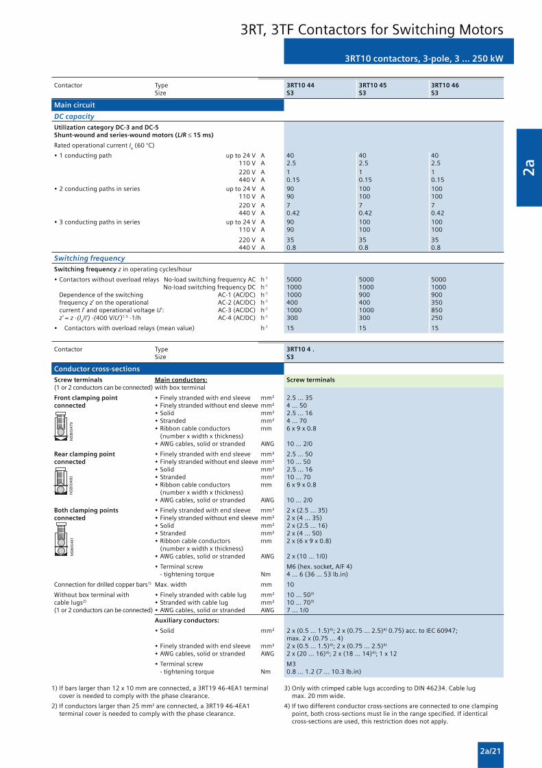
2a
2a/21
3RT10 contactors, 3-pole, 3 ... 250 kW
3RT, 3TF Contactors for Switching Motors
��������
�������
������
Contactor Type 3RT10 44 3RT10 45 3RT10 46 Size S3 S3 S3
Main circuit
DC capacity
Utilization category DC-3 and DC-5Shunt-wound and series-wound motors (L/R ≤ 15 ms)
Rated operational current Ie (60 °C)
• 1 conducting path up to 24 V A 40 40 40110 V A 2.5 2.5 2.5220 V A 1 1 1440 V A 0.15 0.15 0.15
• 2 conducting paths in series up to 24 V A 90 100 100110 V A 90 100 100220 V A 7 7 7440 V A 0.42 0.42 0.42
• 3 conducting paths in series up to 24 V A 90 100 100110 V A 90 100 100
220 V A 35 35 35440 V A 0.8 0.8 0.8
Switching frequency
Switching frequency z in operating cycles/hour
• Contactors without overload relays No-load switching frequency AC h-1 5000 5000 5000No-load switching frequency DC h-1 1000 1000 1000
Dependence of the switching AC-1 (AC/DC) h-1 1000 900 900frequency z’ on the operational AC-2 (AC/DC) h-1 400 400 350current I’ and operational voltage U’: AC-3 (AC/DC) h-1 1000 1000 850z’ = z ·(I
e/I’) ·(400 V/U’)1.5 ·1/h AC-4 (AC/DC) h-1 300 300 250
• Contactors with overload relays (mean value) h-1 15 15 15
Contactor Type 3RT10 4 . Size S3
Conductor cross-sections
Screw terminals Main conductors: Screw terminals(1 or 2 conductors can be connected) with box terminal
Front clamping point • Finely stranded with end sleeve mm² 2.5 ... 35connected • Finely stranded without end sleeve mm² 4 ... 50
• Solid mm² 2.5 ... 16• Stranded mm² 4 ... 70• Ribbon cable conductors mm 6 x 9 x 0.8
(number x width x thickness)• AWG cables, solid or stranded AWG 10 ... 2/0
Rear clamping point • Finely stranded with end sleeve mm² 2.5 ... 50connected • Finely stranded without end sleeve mm² 10 ... 50
• Solid mm² 2.5 ... 16• Stranded mm² 10 ... 70• Ribbon cable conductors mm 6 x 9 x 0.8
(number x width x thickness)• AWG cables, solid or stranded AWG 10 ... 2/0
Both clamping points • Finely stranded with end sleeve mm² 2 x (2.5 ... 35)connected • Finely stranded without end sleeve mm² 2 x (4 ... 35)
• Solid mm² 2 x (2.5 ... 16)• Stranded mm² 2 x (4 ... 50)• Ribbon cable conductors mm 2 x (6 x 9 x 0.8)
(number x width x thickness)• AWG cables, solid or stranded AWG 2 x (10 ... 1/0)
• Terminal screw M6 (hex. socket, A/F 4) - tightening torque Nm 4 ... 6 (36 ... 53 lb.in)
Connection for drilled copper bars1) Max. width mm 10
Without box terminal with • Finely stranded with cable lug mm² 10 ... 503)
cable lugs2) • Stranded with cable lug mm² 10 ... 703)
(1 or 2 conductors can be connected) • AWG cables, solid or stranded AWG 7 ... 1/0
Auxiliary conductors:
• Solid mm² 2 x (0.5 ... 1.5)4); 2 x (0.75 ... 2.5)4) 0.75) acc. to IEC 60947;max. 2 x (0.75 ... 4)
• Finely stranded with end sleeve mm² 2 x (0.5 ... 1.5)4); 2 x (0.75 ... 2.5)4)
• AWG cables, solid or stranded AWG 2 x (20 ... 16)4); 2 x (18 ... 14)4); 1 x 12
• Terminal screw M3 - tightening torque Nm 0.8 ... 1.2 (7 ... 10.3 lb.in)
1) If bars larger than 12 x 10 mm are connected, a 3RT19 46-4EA1 terminalcover is needed to comply with the phase clearance.
2) If conductors larger than 25 mm2 are connected, a 3RT19 46-4EA1terminal cover is needed to comply with the phase clearance.
3) Only with crimped cable lugs according to DIN 46234. Cable lugmax. 20 mm wide.
4) If two different conductor cross-sections are connected to one clampingpoint, both cross-sections must lie in the range specified. If identicalcross-sections are used, this restriction does not apply.

2a
2a/22
3RT10 contactors, 3-pole, 3 ... 250 kW
3RT, 3TF Contactors for Switching Motors
��������� � � � �
� �
Contactor Type 3RT10 54 3RT10 55 3RT10 56 Size S6 S6 S6
General data
Permissible mounting positionThe contactors are designed for operation on a vertical mounting surface.
Mechanical endurance Opera- 10 milliontingcycles
Electrical endurance 1)
Rated insulation voltage Ui (degree of pollution 3) V 1000
Rated impulse withstand voltage Uimp kV 8
Safe isolation between the coil and the main contacts V 690acc. to EN 60947-1, Appendix N
Mirror contacts Yes, acc. to EN 60947-4-1, Appendix FA mirror contact is an auxiliary NC contact that cannot be closedsimultaneously with a NO main contact.
Permissible ambient temperature During operation °C -25 ... +60/+55 with AS-InterfaceDuring storage °C -55 ... +80
Degree of protection acc. to EN 60947-1, Appendix C IP00/open, coil assembly IP20Touch protection acc. to EN 50274 Finger-safe with cover
Shock resistance Rectangular pulse g/ms 8.5/5 and 4.2/10Sine pulse g/ms 13.4/5 and 6.5/10
Conductor cross-sections 2)
Electromagnetic compatibility (EMC) 3)
Short-circuit protection
Main circuit For short-circuit protection for contactors with overload relays seeFuse links, gL/gG Protection Equipment: Overload RelaysLV HRC 3NA, DIAZED 5SB, NEOZED 5SE
- acc. to IEC 60947-4-1/ • Type of coordination “1” A 355 355EN 60947-4-1 • Type of coordination “2” A 315 315
• Weld-free4) A 80 160
Auxiliary circuit
• Fuse links gL/gG A 10DIAZED 5SB, NEOZED 5SE(weld-free protection at Ik ≥ 1 kA)
• Or miniature circuit breakers with C characteristic (Ik < 400 A)
Contactor Type 3RT10 5 . Size S6
Control
Operating range of the solenoid AC/DC (UC) 0.8 x Us min ... 1.1 x Us max
Power consumption of the solenoid(when coil is cool and rated range Us min ... Us max)
• Conventional operating mechanism
- AC operation Closing at Us min VA/p.f. 250/0.9 Closing at Us max VA/p.f. 300/0.9
Closed at Us min VA/p.f. 4.8/0.8 Closed at Us max VA/p.f. 5.8/0.8
- DC operation Closing at Us min W 300 Closing at Us max W 360 Closed at Us min W 4.3
Closed at Us max W 5.2
• Solid-state operating mechanism
- AC operation Closing at Us min VA/p.f. 190/0.8 Closing at Us max VA/p.f. 280/0.8 Closed at Us min VA/p.f. 3.5/0.5 Closed at Us max VA/p.f. 4.4/0.4
- DC operation Closing at Us min W 250 Closing at Us max W 320 Closed at Us min W 2.3 Closed at Us max W 2.8
PLC control input (EN 61131-2/type 2) 24 V DC/≤ 30 mA power consumption,(operating range 17 ... 30 V DC)
1) For endurance of the main contacts see page 2a/5.
2) For conductor cross-sections see page 2a/25.
3) For electromagnetic compatibility (EMC) see page 2/10.
4) Test conditions according to IEC 60947-4-1.

2a
2a/23
3RT10 contactors, 3-pole, 3 ... 250 kW
3RT, 3TF Contactors for Switching Motors
Contactor Type 3RT10 5 . Size S6
Control
Operating times (Total break time = Opening delay + Arcing time)
• Conventional operating mechanism
- with 0.8 x Us min ... 1.1 x Us max Closing delay ms 20 ... 95Opening delay ms 40 ... 60
- with Us min ... Us max Closing delay ms 25 ... 50Opening delay ms 40 ... 60
• Solid-state operating mechanism, actuated via PLC input
- with 0.8 x Us min ... 1.1 x Us max Closing delay ms 35 ... 75Opening delay ms 80 ... 90
- with Us min ... Us max Closing delay ms 40 ... 60Opening delay ms 80 ... 90
• Solid-state operating mechanism, actuated via A1/A2
- with 0.8 x Us min ... 1.1 x Us max Closing delay ms 95 ... 135Opening delay ms 80 ... 90
- with Us min ... Us max Closing delay ms 100 ... 120Opening delay ms 80 ... 90
Arcing time ms 10 ... 15
Contactor Type 3RT10 54 3RT10 55 3RT10 56 Size S6 S6 S6
Main circuit
AC capacity
Utilization category AC-1Switching resistive loads
Rated operational currents Ie at 40 °C up to 690 V A 160 185 215at 60 °C up to 690 V A 140 160 185
at 60 °C up to 1000 V A 80 90 100
Rated power for AC loads1) at 415 V kW 92 105 121P.f. = 0.95 (at 60 °C)
Minimum conductor cross-section for loads with Ie At 40 °C mm2 70 95 95At 60 °C mm2 50 70 95
Utilization category AC-2 and AC-3
Rated operational currents Ie up to 500 V A 115 150 185690 V A 115 150 170
1000 V A 53 65 65
Rated power of slipring at 215 V kW 37 50 61or squirrel-cage motors at 50 and 60 Hz 415 V kW 64 84 104
500 V kW 81 105 132690 V kW 113 146 167
1000 V kW 75 90 90
Thermal load capacity 10 s current2) A 1100 1300 1480
Power loss per main current path at Ie/AC-3/500 V W 7 9 13
Utilization category AC-4 (for Ia = 6 x Ie)
Rated operational current Ie up to 415 V A 97 132 160
Rated power for squirrel-cage at 415 V kW 55 75 90motors with 50 Hz and 60 Hz
• The following applies to a contact endurance of about 200000 operating cycles:
- rated operational currents Ie up to 500 V A 54 68 81690 V A 48 57 65
1000 V A 34 38 42
- rated power for squirrel-cage motors at 230 V kW 16 20 25with 50 Hz and 60 Hz 415 V kW 29 38 45
500 V kW 37 47 57690 V kW 48 55 65
1000 V kW 49 55 60
1) Industrial furnaces and electric heaters with resistance heating, etc.(increased power consumption on heating up has been taken intoaccount).
2) According to IEC 60947-4-1.For rated values for various start-up conditions see Protection Equipment:Overload Relays.

2a
2a/24
3RT10 contactors, 3-pole, 3 ... 250 kW
3RT, 3TF Contactors for Switching Motors
Contactor Type 3RT10 54 3RT10 55 3RT10 56 Size S6 S6 S6
Main circuit
AC capacity
Utilization category AC-6aswitching AC transformers
Rated operational current Ie
• For inrush current n = 20 up to 690 V A 115 148 148
• For inrush current n = 30 up to 690 V A 90 99 99
Rating P
• For inrush current n = 20 at 415 V kVA 79 102 102
• For inrush current n = 30 at 415 V kVA 62 68 68
For deviating inrush current factors x, the power must be recalculated as follows:Px = Pn 30 · 30/x
Utilization category AC-6bSwitching low-inductance (low-loss, metallized dielectric) AC capacitorsAmbient temperature 40 °C
Rated operational currents Ie up to 500 V A 105 125 145
Rated power for single capacitors or at 230 V kvar 42 50 58banks of capacitors (minimum inductance 415 V kvar 72 86 100of 6 mH between capacitors connected 500 V kvar 90 108 125in parallel) at 50 Hz, 60 Hz 690 V kvar 72 86 100
DC capacity
Utilization category DC-1Switching resistive load (L/R ≤ 1 ms)
Rated operational current Ie (at 60 °C)
• 1 conducting path up to 24 V A 160110 V A 18
220 V A 3.4440 V A 0.8
• 2 conducting paths in series up to 24 V A 160110 V A 160
220 V A 20440 V A 3.2
• 3 conducting paths in series up to 24 V A 160110 V A 160
220 V A 160440 V A 11.5
Utilization category DC-3 and DC-5Shunt-wound and series-wound motors (L/R ≤ 15 ms)
Rated operational current Ie (at 60 °C)
• 1 conducting path up to 24 V A 160110 V A 2.5
220 V A 0.6440 V A 0.17
• 2 conducting paths in series up to 24 V A 160110 V A 160
220 V A 2.5440 V A 0.65
• 3 conducting paths in series up to 24 V A 160110 V A 160
220 V A 160440 V A 1.4
Switching frequency
Switching frequency z in operating cycles/hour
• Contactors without overload relays No-load switching frequency h-1 2000 2000
Dependence of the switching AC-1 h-1 800 800frequency z’ on the operational AC-2 h-1 400 300current I’ and operational voltage U’: AC-3 h-1 1000 750z’ = z ·(Ie/I’) ·(400 V/U’)1.5 ·1/h AC-4 h-1 130 130
• Contactors with overload relays (mean value) h-1 60 60

2a
2a/25
3RT10 contactors, 3-pole, 3 ... 250 kW
3RT, 3TF Contactors for Switching Motors
��������
�������
�������
��������
�������
�������
Contactor Type 3RT10 5 . Size S6
Conductor cross-sections of main conductors with box terminal
Screw terminals Main conductors: Screw terminals(1 or 2 conductors can be connected) with 3RT19 55-4G box terminal (55 kW)
Front or rear clamping point • Finely stranded with end sleeve mm² 16 ... 70connected • Finely stranded without end sleeve mm² 16 ... 70
• Stranded mm² 16 ... 70• Ribbon cable conductors mm Min. 3 x 9 x 0.8, max. 6 x 15.5 x 0.8
(number x width x thickness)• AWG cables, AWG 6 ... 2/0
solid or stranded
Both clamping points • Finely stranded with end sleeve mm² Max. 1 x 50, 1 x 70connected • Finely stranded without end sleeve mm² Max. 1 x 50, 1 x 70
• Stranded mm² Max. 2 x 70• Ribbon cable conductors mm Max. 2 x (6 x 15.5 x 0.8)
(number x width x thickness)• AWG cables, AWG Max. 2 x 1/0
solid or stranded
• Terminal screw M10 (hexagon socket, A/F 4)- tightening torque Nm 10 ... 12 (90 ... 110 lb.in)
Screw terminals Main conductor:(1 or 2 conductors can be connected) With 3RT19 56-4G box terminal
Front or rear clamping point • Finely stranded with end sleeve mm² 16 ... 120connected • Finely stranded without end sleeve mm² 16 ... 120
• Stranded mm² 16 ... 120• Ribbon cable conductors mm Min. 3 x 9 x 0.8, max. 10 x 15.5 x 0.8
(number x width x thickness)• AWG cables, AWG 6 ... 250 kcmil
solid or stranded
Both clamping points • Finely stranded with end sleeve mm² Max. 1 x 95, 1 x 120connected • Finely stranded without end sleeve mm² Max. 1 x 95, 1 x 120
• Stranded mm² Max. 2 x 120• Ribbon cable conductors mm Max. 2 x (10 x 15.5 x 0.8)
(number x width x thickness)• AWG cables, AWG Max. 2 x 3/0
solid or stranded
• Terminal screw M10 (hexagon socket, A/F 4)- tightening torque Nm 10 ... 12 (90 ... 110 lb.in)
Screw terminals Main conductors:without box terminal/busbar connection
• Finely stranded with cable lug1) mm2 16 ... 95• Stranded with cable lug1) mm2 25 ... 120• AWG cables, AWG 4 ... 250 kcmil
solid or stranded• Connecting bar (max. width) mm 17
• Terminal screw M8 x 25 (A/F 13)- Tightening torque Nm 10 ... 14 (89 ... 124 lb.in)
Auxiliary conductors:
• Solid mm2 2 x (0.5 ... 1.5)2); 2 x (0.75 ... 2.5)2) 0.75) acc. to IEC 60947;max. 2 x (0.75 ... 4)
• Finely stranded with end sleeve mm2 2 x (0.5 ... 1.5)2); 2 x (0.75 ... 2.5)2)
• AWG cables, AWG 2 x (18 ... 14)solid or stranded
• Terminal screw M3 (PZ 2)- tightening torque Nm 0.8 ... 1.2 (7 ... 10.3 lb.in)
1) When connecting cable lugs to DIN 46235, use 3RT19 56-4EA1 terminalcover for conductor cross-sections from 95 mm² to ensure phase spacing.
2) If two different conductor cross-sections are connected to one clampingpoint, both cross-sections must lie in the range specified. If identicalcross-sections are used, this restriction does not apply.

2a
2a/26
3RT10 contactors, 3-pole, 3 ... 250 kW
3RT, 3TF Contactors for Switching Motors
��������� � � � �
� �
Contactor Type 3RT10 64 3RT10 65 3RT10 66 Size S10 S10 S10
General data
Permissible mounting position The contactors are designed foroperation on a vertical mountingsurface.
Mechanical endurance Opera- 10 milliontingcycles
Electrical endurance 1)
Rated insulation voltage Ui (degree of pollution 3) V 1000
Rated impulse withstand voltage Uimp kV 8
Safe isolation between the coil and the main contacts V 690acc. to EN 60947-1, Appendix N
Mirror contacts Yes, acc. to EN 60947-4-1, Appendix FA mirror contact is an auxiliary NC contact that cannot be closedsimultaneously with a NO main contact.
Permissible ambient temperature During operation °C -25 ... +60/+55 with AS-InterfaceDuring storage °C -55 ... +80
Degree of protection acc. to EN 60947-1, Appendix C IP00/open, coil assembly IP20Touch protection acc. to EN 50274 Finger-safe with cover
Shock resistance Rectangular pulse g/ms 8.5/5 and 4.2/10Sine pulse g/ms 13.4/5 and 6.5/10
Conductor cross-sections 2)
Electromagnetic compatibility (EMC) 3)
Short-circuit protection
Main circuitFuse links, gL/gGLV HRC 3NA, DIAZED 5SB, NEOZED 5SE
- acc. to IEC 60947-4-1/ • Type of coordination “1” A 500EN 60947-4-1 • Type of coordination “2” A 400
• Weld-free4) A 250
Auxiliary circuit
• Fuse links gL/gG A 10DIAZED 5SB, NEOZED 5SE(weld-free protection at Ik ≥ 1 kA)
Or miniature circuit breakers with C characteristic(short-circuit current Ik < 400 A)
Control
Operating range of the solenoid AC/DC (UC) 0.8 x Us min ... 1.1 x Us max
Power consumption of the solenoid(when coil is cool and rated range Us min ... Us max)
• Conventional operating mechanism
- AC operation Closing at Us min VA/p.f. 490/0.9Closing at Us max VA/p.f. 590/0.9Closed at Us min VA/p.f. 5.6/0.9Closed at Us max VA/p.f. 6.7/0.9
- DC operation Closing at Us min W 540Closing at Us max W 650Closed at Us min W 6.1Closed at Us max W 7.4
• Solid-state operating mechanism
- AC operation Closing at Us min VA/p.f. 400/0.8Closing at Us max VA/p.f. 530/0.8Closed at Us min VA/p.f. 4/0.5Closed at Us max VA/p.f. 5/0.4
- DC operation Closing at Us min W 440Closing at Us max W 580Closed at Us min W 3.2Closed at Us max W 3.8
PLC control input (EN 61131-2/type 2) 24 V DC/≤ 30 mA power consumption, (operating range 17 ... 30 V DC)
1) For endurance of the main contacts see page 2a/5.
2) For conductor cross-sections see page 2a/29.
3) For electromagnetic compatibility (EMC) see page 2/10.
4) Test conditions according to IEC 60947-4-1.

2a
2a/27
3RT10 contactors, 3-pole, 3 ... 250 kW
3RT, 3TF Contactors for Switching Motors
Contactor Type 3RT10 64 3RT10 65 3RT10 66 Size S10 S10 S10
Control
Operating times (Total break time = Opening delay + Arcing time)
• Conventional operating mechanism
- with 0.8 x Us min ... 1.1 x Us max Closing delay ms 30 ... 95 Opening delay ms 40 ... 80
- for Us min ... Us max Closing delay ms 35 ... 50 Opening delay ms 50 ... 80
• Solid-state operating mechanism, actuated via A1/A2
- with 0.8 x Us min ... 1.1 x Us max Closing delay ms 105 ... 145 Opening delay ms 80 ... 100
- for Us min ... Us max Closing delay ms 110 ... 130 Opening delay ms 80 ... 100
• Solid-state operating mechanism, actuated via PLC input
- with 0.8 x Us min ... 1.1 x Us max Closing delay ms 45 ... 80 Opening delay ms 80 ... 100
- for Us min ... Us max Closing delay ms 50 ... 65 Opening delay ms 80 ... 100
• Arcing time ms 10 ... 15
Main circuit
AC capacity
Utilization category AC-1Switching resistive loads
Rated operational currents Ie at 40 °C up to 690 V A 275 330at 60 °C up to 690 V A 250 300
at 60 °C up to 1000 V A 100 150
Rated power for AC loads1) at 415 V kW 164 197P.f. = 0.95 (at 60 °C)
Minimum conductor cross-section for at 40 °C mm2 150 185loads with Ie at 60 °C mm2 120 185
Utilization category AC-2 and AC-3
Rated operational currents Ie up to 500 V A 225 265 300690 V A 225 265 280
1000 V A 68 95 95
Rated power of slipring at 230 V kW 73 85 97or squirrel-cage motors at 50 and 60 Hz 415 V kW 128 151 171
500 V kW 160 189 215690 V kW 223 265 280
1000 V kW 90 132 132
Thermal load capacity 10 s current2) A 1800 2400 2400
Power loss per main current path at Ie/AC-3/500 V W 17 18 22
Utilization category AC-4 (for Ia = 6 x Ie)
Rated operational current Ie up to 415 V A 195 230 280
Rated power for squirrel-cage motors with at 415 V kW 110 132 16050 Hz and 60 Hz
• The following applies to a contact endurance of about 200000 operating cycles:
- rated operational currents Ie up to 500 V A 96 117 125690 V A 85 105 115
1000 V A 42 57 57
- rated power for squirrel-cage motors at 230 V kW 30 37 40with 50 Hz and 60 Hz 415 V kW 54 66 71
500 V kW 67 82 87690 V kW 82 102 112
1000 V kW 59 80 80
Utilization category AC-6aswitching AC transformers
Rated operational current Ie
• For inrush current n = 20 up to 690 V A 227 265 273• For inrush current n = 30 up to 690 V A 151 182 182
Rated power P
• For inrush current n = 20 at 415 V kVA 157 183 189• For inrush current n = 30 at 415 V kVA 105 126 126
For deviating inrush current factors x, the power must be recalculated as follows:Px = Pn 30 · 30/x
1) Industrial furnaces and electric heaters with resistance heating, etc.(increased power consumption on heating up has been taken intoaccount).
2) According to IEC 60947-4-1.For rated values for various start-up conditions see Protection Equipment:Overload Relays.

2a
2a/28
3RT10 contactors, 3-pole, 3 ... 250 kW
3RT, 3TF Contactors for Switching Motors
Contactor Type 3RT10 64 3RT10 65 3RT10 66 Size S10 S10 S10
Main circuit
AC capacity
Utilization category AC-6bSwitching low-inductance (low-loss, metallized dielectric) AC capacitorsAmbient temperature 40 °C
Rated operational currents Ie up to 500 V A 183 220
Rated power for single capacitors or at 230 V kvar 73 88banks of capacitors (minimum inductance 415 V kvar 127 152of 6 μH between capacitors connected in 500 V kvar 159 191parallel) at 50 Hz, 60 Hz and 690 V kvar 127 152
DC capacity
Utilization category DC-1Switching resistive load (L/R ≤ 1 ms)
Rated operational current Ie (at 60 °C)
• 1 conducting path up to 24 V A 200 300110 V A 18 33
220 V A 3.4 3.8440 V A 0.8 0.9
• 2 conducting paths in series up to 24 V A 200 300110 V A 200 300
220 V A 20 300440 V A 3.2 4
• 3 conducting paths in series up to 24 V A 200 300110 V A 200 300
220 V A 200 300440 V A 11.5 11
Utilization category DC-3 and DC-5Shunt-wound and series-wound motors (L/R ≤ 15 ms)
Rated operational current Ie (at 60 °C)
• 1 conducting path up to 24 V A 200 300110 V A 2.5 3
220 V A 0.6 0.6440 V A 0.17 0.18
• 2 conducting paths in series up to 24 V A 200 300110 V A 200 300
220 V A 2.5 2.5440 V A 0.65 0.65
• 3 conducting paths in series up to 24 V A 200 300110 V A 200 300
220 V A 200 300440 V A 1.4 1.4
Switching frequency
Switching frequency z in operating cycles/hour
• Contactors without overload relays No-load switching frequency h-1 2000 2000 2000
Dependence of the switching AC-1 h-1 750 800 750frequency z’ on the operational AC-2 h-1 250 300 250current I’ and operational voltage U’: AC-3 h-1 500 700 500z’ = z ·(Ie/I’) ·(400 V/U’)1.5 ·1/h AC-4 h-1 130 130 130
• Contactors with overload relays (mean value) h-1 60 60 60

2a
2a/29
3RT10 contactors, 3-pole, 3 ... 250 kW
3RT, 3TF Contactors for Switching Motors
��������
��������
������
Contactor Type 3RT10 6 . Size S10
Conductor cross-sections
Screw terminals Main conductors: Screw terminalsWith 3RT19 66-4G box terminal
Front clamping point • Finely stranded with end sleeve mm² 70 ... 240connected • Finely stranded without end sleeve mm² 70 ... 240
• Stranded mm² 95 ... 300• AWG cables, AWG 3/0 ... 600 kcmil
solid or stranded• Ribbon cable conductors mm Min. 6 x 9 x 0.8, max. 20 x 24 x 0.5(number x width x thickness)
Rear clamping point • Finely stranded with end sleeve mm² 120 ... 185connected • Finely stranded without end sleeve mm² 120 ... 185
• Stranded mm² 120 ... 240• AWG cables, AWG 250 ... 500 kcmil
solid or stranded• Ribbon cable conductors mm Min. 6 x 9 x 0.8, max. 20 x 24 x 0.5
(number x width x thickness)
Both clamping points • Finely stranded with end sleeve mm² Min. 2 x 50, max. 2 x 185connected • Finely stranded without end sleeve mm² Min. 2 x 50, max. 2 x 185
• Stranded mm² Min. 2 x 70, max. 2 x 240• AWG cables, AWG Min. 2 x 2/0, max. 2 x 500 kcmil
solid or stranded• Ribbon cable conductors mm Max. 2 x (20 x 24 x 0.5)
(number x width x thickness)
• Terminal screws M12 (hexagon socket, A/F 5)- tightening torque Nm 20 ... 22 (180 ... 195 lb.in)
Screw terminals Main conductors:without box terminal/busbar connection
• Finely stranded with cable lug1) mm² 50 ... 240• Stranded with cable lug1) mm² 70 ... 240• AWG cables, AWG 2/0 ... 500 kcmil
solid or stranded• Connecting bar (max. width) mm 25
• Terminal screws M10 x 30 (A/F 17)- tightening torque Nm 14 ... 24 (124 ... 210 lb.in)
Auxiliary conductors:
• Solid mm2 2 x (0.5 ... 1.5)2); 2 x (0.75 ... 2.5)2) 0.75) acc. to IEC 60947;max. 2 x (0.75 ... 4)
• Finely stranded with end sleeve mm2 2 x (0.5 ... 1.5)2); 2 x (0.75 ... 2.5)2)
• AWG cables, AWG 2 x (18 ... 14)solid or stranded
• Terminal screws M3 (PZ 2) - tightening torque Nm 0.8 ... 1.2 (7 ... 10.3 lb.in)
1) When connecting cable lugs to DIN 46234, the 3RT19 66-4EA1 terminalcover must be used for conductor cross-sections of 240 mm² and more aswell as DIN 46235 for conductor cross-sections of 185 mm² and more tokeep the phase clearance.
2) If two different conductor cross-sections are connected to one clampingpoint, both cross-sections must lie in the range specified. If identicalcross-sections are used, this restriction does not apply.

2a
2a/30
3RT10 contactors, 3-pole, 3 ... 250 kW
3RT, 3TF Contactors for Switching Motors
��������� � � � �
� �
Contactor Type 3RT10 75 3RT10 76 Size S12 S12
General data
Permissible mounting positionThe contactors are designed for operation on a vertical mounting surface.
Mechanical endurance Opera- 10 milliontingcycles
Electrical endurance 1)
Rated insulation voltage Ui (degree of pollution 3) V 1000
Rated impulse withstand voltage Uimp kV 8
Safe isolation between the coil and the main contacts V 690acc. to EN 60947-1, Appendix N
Mirror contacts Yes, acc. to EN 60947-4-1, Appendix FA mirror contact is an auxiliary NC contact that cannot be closedsimultaneously with a NO main contact.
Permissible ambient temperature During operation °C -25 ... +60/+55 with AS-InterfaceDuring storage °C -55 ... +80
Degree of protection acc. to EN 60947-1, Appendix C IP00/open, coil assembly IP20Touch protection acc. to EN 50274 Finger-safe with cover
Shock resistance Rectangular pulse g/ms 8.5/5 and 4.2/10Sine pulse g/ms 13.4/5 and 6.5/10
Conductor cross-sections 2)
Electromagnetic compatibility (EMC) 3)
Short-circuit protection
Main circuitFuse links, gL/gG LV HRC 3NA, DIAZED 5SB, NEOZED 5SE
- acc. to IEC 60947-4-1/ • Type of coordination “1” A 630 630EN 60947-4-1 • Type of coordination “2” A 500 500
• Weld-free4) A 250 315
Auxiliary circuit
• Fuse links gL/gG A 10DIAZED 5SB, NEOZED 5SE(weld-free protection for Ik ≥ 1 kA)
or miniature circuit breakers with C characteristic(short-circuit current Ik < 400 A)
Control
Operating range of the solenoid AC/DC (UC) 0.8 x Us min ... 1.1 x Us max
Power consumption of the solenoid(when coil is cool and rated range Us min ... Us max)
• Conventional operating mechanism
- AC operation Closing at Us min VA/p.f. 700/0.9Closing at Us max VA/p.f. 830/0.9Closed at Us min VA/p.f. 7.6/0.9Closed at Us max VA/p.f. 9.2/0.9
- DC operation Closing at Us min W 770Closing at Us max W 920Closed at Us min W 8.5Closed at Us max W 10
• Solid-state operating mechanism
- AC operation Closing at Us min VA/p.f. 560/0.8Closing at Us max VA/p.f. 750/0.8Closed at Us min VA/p.f. 5.4/0.8Closed at Us max VA/p.f. 7/0.8
- DC operation Closing at Us min W 600Closing at Us max W 800Closed at Us min W 4Closed at Us max W 5
PLC control input (EN 61131-2/type 2) 24 V DC/≤ 30 mA power consumption, (operating range 17 ... 30 V DC)
1) For endurance of the main contacts see page 2a/5.
2) For conductor cross-sections see page 2a/33.
3) For electromagnetic compatibility (EMC) see page 2/10.
4) Test conditions according to IEC 60947-4-1.

2a
2a/31
3RT10 contactors, 3-pole, 3 ... 250 kW
3RT, 3TF Contactors for Switching Motors
Contactor Type 3RT10 75 3RT10 76 Size S12 S12
Control
Operating times(Total break time = Opening delay + Arcing time)
• Conventional operating mechanism
- with 0.8 x Us min ... 1.1 x Us max Closing delay ms 45 ... 100 Opening delay ms 60 ... 100
- for Us min ... Us max Closing delay ms 50 ... 70 Opening delay ms 70 ... 100
• Solid-state operating mechanism, actuated via A1/A2
- with 0.8 x Us min ... 1.1 x Us max Closing delay ms 120 ... 150 Opening delay ms 80 ... 100
- for Us min ... Us max Closing delay ms 125 ... 150 Opening delay ms 80 ... 100
• Solid-state operating mechanism, actuated via PLC input
- with 0.8 x Us min ... 1.1 x Us max Closing delay ms 60 ... 90 Opening delay ms 80 ... 100
- for Us min ... Us max Closing delay ms 65 ... 80 Opening delay ms 80 ... 100
• Arcing time ms 10 ... 15
Main circuit
AC capacity
Utilization category AC-1Switching resistive loads
Rated operational currents Ie at 40 °C up to 690 V A 430 610at 60 °C up to 690 V A 400 550
at 60 °C up to 1000 V A 200 200
Rated power for AC loads1) at 415 V kW 263 362P.f. = 0.95 (at 60 °C)
Minimum conductor cross-section for at 40 °C mm2 2 x 150 2 x 185loads with Ie at 60 °C mm2 240 2 x 185
Utilization category AC-2 and AC-3
Rated operational currents Ie up to 500 V A 400 500690 V A 400 450
1000 V A 180 180
Rated power of slipring at 230 V kW 132 164or squirrel-cage motors at 50 and 60 Hz 415 V kW 231 291
500 V kW 291 363690 V kW 400 453
1000 V kW 250 250
Thermal load capacity 10 s current2) A 3200 4000
Power loss per main current path at Ie/AC-3/500 V W 35 55
Utilization category AC-4 (for Ia = 6 x Ie)
Rated operational current Ie up to 400 V A 350 430
Rated power for squirrel-cage at 415 V kW 200 250motors with 50 Hz and 60 Hz
• The following applies to a contact endurance of about 200000 operating cycles:
- rated operational current Ie up to 500 V A 150 175690 V A 135 150
1000 V A 80 80
- rated power for squirrel-cage motors at 230 V kW 48 56with 50 Hz and 60 Hz 415 V kW 85 98
500 V kW 105 123690 V kW 133 148
1000 V kW 113 113
Utilization category AC-6aswitching AC transformers
Rated operational current Ie
• For inrush current n = 20 up to 690 V A 377 404• For inrush current n = 30 up to 690 V A 251 270
Rating P
• For inrush current n = 20 at 415 V kVA 261 280• For inrush current n = 30 at 415 V kVA 173 187
For deviating inrush current factors x, the power must be recalculated as follows:Px = Pn 30 · 30/x
1) Industrial furnaces and electric heaters with resistance heating, etc.increased power consumption on heating up taken into account).
2) According to IEC 60947-4-1.
For rated values for various start-up conditions see Protection Equipment:Overload Relays.

2a
2a/32
3RT10 contactors, 3-pole, 3 ... 250 kW
3RT, 3TF Contactors for Switching Motors
Contactor Type 3RT10 75 3RT10 76 Size S12 S12
Main circuit
AC capacity
Utilization category AC-6bSwitching low-inductance (low-loss, metallized dielectric) AC capacitorsAmbient temperature 40 °C
Rated operational currents Ie up to 500 V A 287 407
Rated power for single capacitors or at 230 V kvar 114 162banks of capacitors (minimum inductance 415 V kvar 199 282of 6 mH between capacitors connected 500 V kvar 248 352in parallel) at 50 Hz, 60 Hz and 690 V kvar 199 282
DC capacity
Utilization category DC-1Switching resistive load (L/R ≤ 1 ms)
Rated operational current Ie (at 60 °C)
• 1 conducting path up to 24 V A 400110 V A 33
220 V A 3.8440 V A 0.9
• 2 conducting paths in series up to 24 V A 400110 V A 400
220 V A 400440 V A 4
• 3 conducting paths in series up to 24 V A 400110 V A 400
220 V A 400440 V A 11
Utilization category DC-3 and DC-5 Shunt-wound and series-wound motors (L/R ≤ 15 ms)
Rated operational current Ie (at 60 °C)
• 1 conducting path up to 24 V A 400110 V A 3
220 V A 0.6440 V A 0.18
• 2 conducting paths in series up to 24 V A 400110 V A 400
220 V A 2.5440 V A 0.65
• 3 conducting paths in series up to 24 V A 400110 V A 400
220 V A 400440 V A 1.4
Switching frequency
Switching frequency z in operating cycles/hour
• Contactors without overload relays No-load switching frequency h-1 2000 2000
Dependence of the switching AC-1 h-1 700 500frequency z’ on the operational AC-2 h-1 200 170current I’ and operational voltage U’: AC-3 h-1 500 420z’ = z ·(Ie/I’) ·(400 V/U’)1.5 ·1/h AC-4 h-1 130 130
• Contactors with overload relays (mean value) h-1 60 60

2a
2a/33
3RT10 contactors, 3-pole, 3 ... 250 kW
3RT, 3TF Contactors for Switching Motors
��������
�������
������
Contactor Type 3RT10 7 . Size S12
Conductor cross-sections
Screw terminals Main conductors: Screw terminalsWith 3RT19 66-4G box terminal
Front clamping point • Finely stranded with end sleeve mm² 70 ... 240connected • Finely stranded without end sleeve mm² 70 ... 240
• Stranded mm² 95 ... 300• AWG cables, AWG 3/0 ... 600 kcmil
solid or stranded• Ribbon cable conductors mm² Min. 6 x 9 x 0.8, max. 20 x 24 x 0.5
(number x width x thickness)
Rear clamping point • Finely stranded with end sleeve mm² 120 ... 185connected • Finely stranded without end sleeve mm² 120 ... 185
• Stranded mm² 120 ... 240• AWG cables, AWG 250 ... 500 kcmil
solid or stranded• Ribbon cable conductors mm² Min. 6 x 9 x 0.8, max. 20 x 24 x 0.5
(number x width x thickness)
Both clamping points • Finely stranded with end sleeve mm² Min. 2 x 50, max. 2 x 185connected • Finely stranded without end sleeve mm² Min. 2 x 50, max. 2 x 185
• Stranded mm² Min. 2 x 70, max. 2 x 240• AWG cables, AWG Min. 2 x 2/0, max. 2 x 500 kcmil
solid or stranded• Ribbon cable conductors mm² Max. 2 x (20 x 24 x 0.5)
(number x width x thickness)
• Terminal screws M12 (hexagon socket, A/F 5) - tightening torque Nm 20 ... 22 (180 ... 195 lb.in)
Screw terminals Main conductors:without box terminal/busbar connection
• Finely stranded with cable lug1) mm² 50 ... 240 • Stranded with cable lug1) mm² 70 ... 240 • AWG cables, AWG 2/0 ... 500 kcmil
solid or stranded• Connecting bar (max. width) mm 25
• Terminal screws M10 x 30 (A/F 17) - tightening torque Nm 14 ... 24 (124 ... 210 lb.in)
Auxiliary conductors:
• Solid mm² 2 x (0.5 ... 1.5)2); 2 x (0.75 ... 2.5)2) acc. to IEC 60947;max. 2 x (0.75 ... 4)
• Finely stranded with end sleeve mm² 2 x (0.5 ... 1.5)2); 2 x (0.75 ... 2.5)2)
• AWG cables, AWG 2 x (18 ... 14)solid or stranded
• Terminal screws M3 (PZ 2) - tightening torque Nm 0.8 ... 1.2 (7 ... 10.3 lb.in)
1) When connecting cable lugs according to DIN 46234 for conductor cross-sections of 185 mm² and more and according to DIN 46235 for conductorcross-sections of 240 mm² and more, the 3RT19 66-4EA1 terminal covermust be used to keep the phase clearance.
2) If two different conductor cross-sections are connected to one clampingpoint, both cross-sections must lie in the range specified. If identicalcross-sections are used, this restriction does not apply.

2a
2a/34
3RT10 contactors, 3-pole, 3 ... 250 kW
3RT, 3TF Contactors for Switching Motors
Contactor Type 3RT10 15 3RT10 16 3RT10 17 3RT10 23 3RT10 24 3RT10 25 3RT10 26Size S00 S00 S00 S0 S0 S0 S0
CSA and UL rated data
Rated insulation voltage V AC 600 600
Uninterrupted current, at 40 °C Open and enclosed A 20 35
Maximum horsepower ratings(CSA and UL approved values)
Rated power for induction motors at 60 Hz at 200 V hp 1.5 2 3 2 3 5 7.5230 V hp 2 3 3 3 3 5 7.5460 V hp 3 5 7.5 5 7.5 10 15575 V hp 5 7.5 10 7.5 10 15 20
Short-circuit protection at 600 V kA 5 5 5 5 5 5 5(contactor or overload relay) CLASS RK5 fuse A 60 60 60 70 70 70 100
Circuit breakers with overload A 50 50 50 70 70 70 100protection acc. to UL 489
Combination motor controllers type E acc. to UL 508
At 480 V Type — — — 3RV10 2A — — — 8 10 16 22kA — — — 65 65 65 65
At 600 V Type — — — 3RV10 2A — — — 8 10 12.5 12.5kA — — — 25 25 25 25
NEMA/EEMAC ratings
NEMA/EEMAC size hp — 0 — 1
Uninterrupted current Open A — 18 — 27Enclosed A — 18 — 27
Rated power for induction motors at 60 Hz at 200 V hp — 3 — 7.5230 V hp — 3 — 7.5460 V hp — 5 — 10575 V hp — 5 — 10
Overload relays Type 3RU11 16 3RU11 2Setting range A 0.11 ... 12 1.8 ... 25
Contactor Type 3RT10 34 3RT10 35 3RT10 36 3RT10 44 3RT10 45 3RT10 46 Size S2 S2 S2 S3 S3 S3
CSA and UL rated data
Rated insulation voltage V AC 600 600
Uninterrupted current, at 40 °C Open and enclosed A 45 55 50 90 105 105
Maximum horsepower ratings(CSA and UL approved values)
Rated power for induction motors at 200 V hp 10 10 15 20 25 30at 60 Hz 230 V hp 10 15 15 25 30 30
460 V hp 25 30 40 50 60 75575 V hp 30 40 50 60 75 100
Short-circuit protection at 600 V kA 5 5 5 10 10 10(contactor or overload relay) CLASS RK5 fuse A 125 150 200 250 300 350
Circuit breakers with overload A 125 150 200 250 300 400protection acc. to UL 489
Combination motor controllers type E acc. to UL 508
At 480 V Type 3RV10 3 3RV10 4A 32 40 50 63 75 100kA 65 65 65 65 65 65
At 600 V Type 3RV10 4 3RV10 4A 32 40 50 63 75 75kA 25 25 25 30 30 30
NEMA/EEMAC ratings
NEMA/EEMAC size hp — 2 — 3
Uninterrupted current Open A — 45 — 90Enclosed A — 45 — 90
Rated power at 200 V hp — 10 — 25for induction motors with 60 Hz 230 V hp — 15 — 30
460 V hp — 25 — 50575 V hp — 25 — 50
Overload relays Type 3RU11 3 3RU11 4Setting range A 5.5 ... 50 18 ... 100

2a
2a/35
3RT10 contactors, 3-pole, 3 ... 250 kW
3RT, 3TF Contactors for Switching Motors
Contactor Size S00 S0 ... S12Screw terminals Screw terminals Screw terminals
Integrated or 1- and 4-pole Laterallysnap-on snap-on mountableauxiliary switch block auxiliary switch block auxiliary switch block
CSA and UL rated data for the auxiliary contacts
Rated voltage V AC 600 600 600
Switching capacity A 600, Q 600 A 600, Q 600 A 300, Q 30
Uninterrupted current A 10 10 10at 240 V AC
Contactor Type 3RT10 54 3RT10 55 3RT10 56 3RT10 64 3RT10 65 3RT10 66 Size S6 S6 S6 S10 S10 S10
CSA and UL rated data
Rated insulation voltage V AC 600 600
Uninterrupted current, at 40 °C Open and enclosed A 140 195 195 250 330 330
Maximum horsepower ratings(CSA and UL approved values)
Rated power for induction motors at 200 V hp 40 50 60 60 75 100at 60 Hz 230 V hp 50 60 75 75 100 125
460 V hp 100 125 150 150 200 250575 V hp 125 150 200 200 250 300
Short-circuit protection at 600 V kA 10 10 10 10 18 18CLASS RK5/L fuse A 450 500 500 700 800 800Circuit breakers with overload A 350 450 500 500 700 800protection acc. to UL 489
NEMA/EEMAC ratings
NEMA/EEMAC size hp — 4 — — — 5
Uninterrupted current Open A — 150 — — — 300Enclosed A — 135 — — — 270
Rated power at 200 V hp — 40 — — — 75for induction motors 230 V hp — 50 — — — 100with 60 Hz 460 V hp — 100 — — — 200
575 V hp — 100 — — — 200
Overload relays Type 3RB20 56 3RB20 66
Contactor Type 3RT10 75 3RT10 76 Size S12 S12
CSA and UL rated data
Rated insulation voltage V AC 600
Uninterrupted current, at 40 °C Open and enclosed A 400 540
Maximum horsepower ratings(CSA and UL approved values)
Rated power for induction motors at 200 V hp 125 150at 60 Hz 230 V hp 150 200
460 V hp 300 400575 V hp 400 500
Short-circuit protection at 600 V kA 18 30 CLASS L fuse A 1000 1200
Circuit breakers with overload A 900 900protection acc. to UL 489
NEMA/EEMAC ratings
NEMA/EEMAC size hp — 6
Uninterrupted current Open A — 600Enclosed A — 540
Rated power for induction motors at 200 V hp — 150at 60 Hz 230 V hp — 200
460 V hp — 400575 V hp — 400
Overload relays Type 3RB20 66

2a
2a/36
Overview
• 3RT12 vacuum contactors for switching motors
UC operation
The contactors can be operated with AC (40 to 60 Hz) as wellas with DC.
Withdrawable coils
For simple coil replacement, e.g. if the application is replaced,the magnetic coil can be pulled out upwards after the releasemechanism has been actuated and can be replaced by anyother coil of the same size.
Auxiliary contact complement
The contactors can be fitted with up to 8 lateral auxiliarycontacts (identical auxiliary switch blocks from S0 to S12). Ofthese, no more than 4 are permitted to be NC contacts.
Function
3RT12 vacuum contactors
In contrast with the 3RT10 contactors – the main contactsoperate in air under atmospheric conditions – the contact gapsof the 3RT12 vacuum contactors are contained in hermeticallyenclosed vacuum contact tubes. Neither arcs nor arcing gasesare produced. The particular benefit of 3RT12 vacuumcontactors, however, is that their electrical endurance is atleast twice as long as that of 3RT10 contactors. They aretherefore particularly well suited to frequent switching injogging/mixed operation, for example in crane control systems.
Advantages:
• Very long electrical endurance
• High short-time current-carrying capacity for heavy starting
• No reduction of rated operational currents up to 1000 V
• No open arcs, no arcing gases, i.e. no minimum clearancesfrom grounded parts required either
• Longer maintenance intervals
• Increased plant availability
Notes on operation:
• Switching motors with operational voltages Ue > 500 V:
To damp overvoltages and protect the motor coil insulationagainst reignition when switching off induction motors, it isrecommended to connect the 3RT19 66-1PV surgesuppression module – RC varistor – to the outgoing side (2/T1, 4/T2, 6/T3) of the contactors (accessory). This additionalequipment is not required for use in circuits with converters.It could be destroyed by the voltage peaks and harmonicswhich are generated.
• Switching DC voltage:Vacuum contactors are basically unsuitable for switching DCvoltage.
Contactors with conventional operating mechanism
3RT1 . . . - . A version:
The magnetic coil is switched directly on and off with thecontrol supply voltage U
s by way of terminals A1/A2.
Multi-voltage range for the control supply voltage Us:
Several closely adjacent control supply voltages, availablearound the world, are covered by just one coil, for example110-115-120-127 V UC or 220-230-240 V UC.
In addition, allowance is also made for a coil operating range of0.8 times the lower (U
s min) and 1.1 times the upper (U
s max)
rated control supply voltage within which the contactorswitches reliably and no thermal overloading occurs.
Contactors with solid-state operating mechanism
The magnetic coil is supplied selectively with the powerrequired for reliable switching and holding by upstream controlelectronics.
• Extended voltage range for the control supply voltage Us:
Compared with the conventional operating mechanism, thesolid-state operating mechanism covers an even broaderrange of control supply voltages used worldwide within onecoil variant. For example, the coil for 200 to 277 V UC (U
s min
to Us max
) covers the voltages 200-208-220-230-240-254-277 V used worldwide.
• Extended operating range 0.7 to 1.25 × Us:
The wide range of the rated control supply voltage and theadditional coil operating range of 0.8 × U
s min to 1.1 × U
s max
results in an extended coil tolerance of at least 0.7 to1.25 × U
s for the most common control supply voltages 24,
110 and 230 V for which the contactors operate reliably.
• Bridging temporary voltage dips:Control voltage failures dipping to 0 V (at A1/A2) are bridgedfor up to approx. 25 ms to avoid unintentional tripping.
• Defined ON and OFF thresholds:For voltages of ≥ 0.8 × U
s min and higher, the electronics will
reliably switch the contactors on and off ≤ 0.5 × Us min
. Thehysteresis in the switching thresholds prevents the maincontacts from chattering as well as increased wear orwelding when operated in weak, unstable networks. Thisalso prevents thermal overloading of the contactor coil if thevoltage applied is too low (contactor does not close properlyand is continuously operated with overexcitation).
• Low control power consumption when closing and in theclosed state.
Electromagnetic compatibility (EMC)
The contactors with solid-state operating mechanism conformto the requirements for operation in industrial plants.
• Interference immunity
- burst (IEC 61000-4-4): 4 kV
- surge (IEC 61000-4-5): 4 kV
- electrostatic discharge, ESD (IEC 61000-4-2): 8/15 kV
- electromagnetic field (IEC 61000-4-3): 10 V/m
• Emitted interference
- limit value class A according to EN 55011
Note:
In connection with converters, the control cables must berouted separately from the load cables to the converter.
3RT, 3TF Contactors for Switching Motors
3RT12 vacuum contactors, 3-pole, 110 ... 250 kW

2a
2a/37
3RT12 vacuum contactors, 3-pole, 110 ... 250 kW
Technical specifications
Contactor Type 3RT12 64 3RT12 65 3RT12 66 Size S10 S10 S10
General data
Permissible mounting positionThe contactors are designed for operation on a vertical mounting surface.
Mechanical endurance Opera- 10 milliontingcycles
Electrical endurance 1)
Rated insulation voltage Ui (degree of pollution 3) V 1000
Rated impulse withstand voltage Uimp kV 8
Safe isolation between the coil and the main contacts V 690acc. to EN 60947-1, Appendix N
Mirror contacts Yes, acc. to EN 60947-4-1, Appendix FA mirror contact is an auxiliary NC contact that cannot be closedsimultaneously with a NO main contact.
Permissible ambient temperature During operation °C -25 ... +60/+55 with AS-InterfaceDuring storage °C -55 ... +80
Degree of protection acc. to EN 60947-1, Appendix C IP00/open, coil assembly IP20Touch protection acc. to EN 50274 Finger-safe with cover
Shock resistance Rectangular pulse g/ms 8.5/5 and 4.2/10Sine pulse g/ms 13.4/5 and 6.5/10
Conductor cross-sections 2)
Electromagnetic compatibility (EMC) 3)
Short-circuit protection
Main circuitFuse links, gL/gGLV HRC 3NA, DIAZED 5SB, NEOZED 5SE
- Acc. to IEC 60947-4-1/ • Type of coordination “1” A 500EN 60947-4-1 • Type of coordination “2” A 500
• Weld-free4) A 400
Auxiliary circuit
• Fuse links gL/gG A 10DIAZED 5SB, NEOZED 5SE(weld-free protection for Ik ≥ 1 kA)
Or miniature circuit breakers with C characteristic(short-circuit current I
k 400 A)
Control
Operating range of the solenoid AC/DC (UC) 0.8 x Us min ... 1.1 x Us max
Power consumption of the solenoid(when coil is cool and rated range Us min ... Us max)
• Conventional operating mechanism
- AC operation Closing at Us min
VA/p.f. 530/0.9 Closing at U
s maxVA/p.f. 630/0.9
Closed at Us min
VA/p.f. 6.1/0.9 Closed at U
s maxA/p.f. 7.4/0.9
- DC operation Closing at Us min W 580 Closing at Us max W 700 Closed at Us min W 6.8 Closed at Us max W 8.2
Operating times (Total break time = Opening delay + Arcing time)
• Conventional operating mechanism
- with 0.8 x Us min
... 1.1 x Us max
Closing delay ms 30 ... 95 Opening delay ms 40 ... 80
- for Us min ... Us max Closing delay ms 35 ... 50 Opening delay ms 50 ... 80
���������� � � � � � � � � � � � �
1) For endurance of the main contacts see page 2a/5.
2) For conductor cross-sections see page 2a/39.
3) For electromagnetic compatibility (EMC) see page 2/10.
4) Test conditions according to IEC 60947-4-1.
3RT, 3TF Contactors for Switching Motors

2a
2a/38
Contactor Type 3RT12 64 3RT12 65 3RT12 66 Size S10 S10 S10
Main circuit
AC capacity
Utilization category AC-1Switching resistive loads
Rated operational currents Ie at 40 °C up to 1000 V A 330at 60 °C up to 1000 V A 300
Rated power for AC loads1) at 415 V kW 197P.f. = 0.95 (at 60 °C)
Minimum conductor cross-section for at 40 °C mm2 185loads with Ie at 60 °C mm2 185
Utilization category AC-2 and AC-3
Rated operational currents Ie up to 1000 V A 225 265 300
Rated power for slipring at 230 V kW 73 85 97or squirrel-cage motors at 50 and 60 Hz 415 V kW 128 151 171
500 V kW 160 189 215690 V kW 223 265 288
1000 V kW 320 378 428
Thermal load capacity 10 s current2) A 1800 2120 2400
Power loss per conducting path at Ie/AC-3 W 9 12 14
Utilization category AC-4 (for Ia = 6 x Ie)
Rated operational current Ie up to 690 V A 195 230 280
Rated power for squirrel-cage motors at 415 V kW 110 132 160with 50 Hz and 60 Hz
• The following applies to a contact endurance of about 200000 operating cycles:
Rated operational currents Ie up to 690 V A 97 115 1401000 V A 68 81 98
Rated power for squirrel-cage motors at 230 V kW 30 37 45with 50 Hz and 60 Hz 415 V kW 55 65 79
500 V kW 68 81 98690 V kW 94 112 138
1000 V kW 95 114 140
Utilization category AC-6aSwitching AC transformers
Rated operational current Ie
• For inrush current n = 20 up to 690 V A 278• For inrush current n = 30 up to 690 V A 185
Rating P
• For inrush current n = 20 at 415 V kVA 193
• For inrush current n = 30 at 415 V kVA 128
For deviating inrush current factors x,the power must be recalculated as follows:Px = Pn 30 · 30/x
Utilization category AC-6bSwitching low-inductance (low-loss, metallized dielectric) AC capacitorsAmbient temperature 40 °C
Rated operational currents Ie up to 500 V A 220
Rated power for single capacitors or at 230 V kvar 88banks of capacitors (minimum inductance 415 V kvar 152of 6 μH between capacitors connected 500 V kvar 191in parallel) at 50 Hz, 60 Hz and 690 V kvar 152
Switching frequency
Switching frequency z in operating cycles/hour
Contactors without overload relays No-load switching frequency h-1 2000 2000
Dependence of the switching frequency AC-1 h-1 800 750z’ on the operational current I’ and AC-2 h-1 300 250operational voltage U’: AC-3 h-1 750 750z’ = z ·(Ie/I’) ·(400 V/U’)1.5 ·1/h AC-4 h-1 250 250
Contactors with overload relays (mean value) h-1 60 60
1) Industrial furnaces and electric heaters with resistance heating, etc.increased power consumption on heating up taken into account).
2) According to IEC 60947-4-1.For rated values for various start-up conditions see Protection Equipment:Overload Relays.
3RT12 vacuum contactors, 3-pole, 110 ... 250 kW
3RT, 3TF Contactors for Switching Motors

2a
2a/39
Contactor Type 3RT12 6 . Size S10
Main conductor cross-sections
Screw terminals Main conductors: Screw terminalsWith 3RT19 66-4G box terminal
Front clamping point • Finely stranded with end sleeve mm² 70 ...240connected • Finely stranded without end sleeve mm² 70 ...240
• Stranded mm² 95 ...300• AWG cables, solid or stranded AWG 3/0 ... 600 kcmil• Ribbon cable conductors mm Min. 6 x 9 x 0.8, max. 20 x 24 x 0.5
(number x width x thickness)
Rear clamping point • Finely stranded with end sleeve mm² 120 ...185connected • Finely stranded without end sleeve mm² 120 ...185
• Stranded mm² 120 ...240• AWG cables, solid or stranded AWG 250 ...500 kcmil• Ribbon cable conductors mm Min. 6 x 9 x 0.8, max. 20 x 24 x 0.5
(number x width x thickness)
Both clamping points • Finely stranded with end sleeve mm² Min. 2 x 50, max. 2 x 185connected • Finely stranded without end sleeve mm² Min. 2 x 50, max. 2 x 185
• Stranded mm² Min. 2 x 70, max. 2 x 240• AWG cables, solid or stranded AWG Min. 2 x 1/0, max. 2 x 500 kcmil• Ribbon cable conductors mm Max. 2 x (20 x 24 x 0.5)
(number x width x thickness)
• Terminal screws M12 (hexagon socket, A/F 5)- tightening torque Nm 20 ... 22 (180 ... 195 lb.in)
Main conductors:without box terminal/busbar connection
• Finely stranded with cable lug1) mm² 50 ...240 • Stranded with cable lug1) mm² 70 ...240 • AWG cables, solid or stranded AWG 2/0 ...500 kcmil • Connecting bar (max. width) mm 25
• Terminal screws M12 (hexagon socket, A/F 5) - tightening torque Nm 14 ... 24 (124 ... 210 lb.in)
Screw terminals Auxiliary conductors:
• Solid mm² 2 x (0.5 ... 1.5)2); 2 x (0.75 ... 2.5)2) acc. to IEC 60947; max. 2 x (0.75 ... 4) • Finely stranded with end sleeve mm² 2 x (0.5 ... 1.5)2); 2 x (0.75 ... 2.5)2)
• AWG cables, solid or stranded AWG 2 x (18 ... 14)
• Terminal screws M3 (PZ 2) - tightening torque Nm 0.8 ... 1.2 (7 ... 10.3 lb.in)
��������
�������
������
1) When connecting cable lugs according to DIN 46234 for conductor cross-sections of 185 mm² and more and according to DIN 46235 for conductorcross-sections of 240 mm² and more, the 3RT19 66-4EA1 terminal covermust be used to keep the phase clearance.
2) If two different conductor cross-sections are connected to one clampingpoint, both cross-sections must lie in the range specified. If identicalcross-sections are used, this restriction does not apply.
3RT12 vacuum contactors, 3-pole, 110 ... 250 kW
3RT, 3TF Contactors for Switching Motors
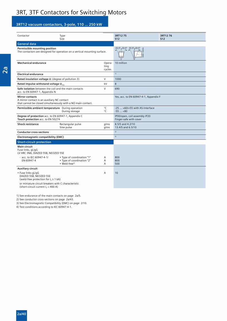
2a
2a/40
Contactor Type 3RT12 75 3RT12 76Size S12 S12
General data
Permissible mounting positionThe contactors are designed for operation on a vertical mounting surface.
Mechanical endurance Opera- 10 milliontingcycles
Electrical endurance 1)
Rated insulation voltage Ui (degree of pollution 3) V 1000
Rated impulse withstand voltage Uimp kV 8
Safe isolation between the coil and the main contacts V 690acc. to EN 60947-1, Appendix N
Mirror contacts Yes, acc. to EN 60947-4-1, Appendix FA mirror contact is an auxiliary NC contactthat cannot be closed simultaneously with a NO main contact.
Permissible ambient temperature During operation °C -25 ... +60/+55 with AS-InterfaceDuring storage °C -55 ... +80
Degree of protection acc. to EN 60947-1, Appendix C IP00/open, coil assembly IP20Touch protection acc. to EN 50274 Finger-safe with cover
Shock resistance Rectangular pulse g/ms 8.5/5 and 4.2/10Sine pulse g/ms 13.4/5 and 6.5/10
Conductor cross-sections 2)
Electromagnetic compatibility (EMC) 3)
Short-circuit protection
Main circuitFuse links, gL/gGLV HRC 3NA, DIAZED 5SB, NEOZED 5SE
- acc. to IEC 60947-4-1/ • Type of coordination “1” A 800EN 60947-4 • Type of coordination “2” A 800
• Weld-free4) A 500
Auxiliary circuit
• Fuse links gL/gG A 10DIAZED 5SB, NEOZED 5SE(weld-free protection for Ik ≥ 1 kA)
or miniature circuit breakers with C characteristic(short-circuit current Ik < 400 A)
���������� � � � � � � � � � � � �
1) See endurance of the main contacts on page 2a/5.2) See conductor cross-sections on page 2a/43.3) See Electromagnetic Compatibility (EMC) on page 2/10.4) Test conditions according to IEC 60947-4-1.
3RT12 vacuum contactors, 3-pole, 110 ... 250 kW
3RT, 3TF Contactors for Switching Motors

2a
2a/41
1) Industrial furnaces and electric heaters with resistance heating, etc.increased power consumption on heating up taken into account).
2) According to IEC 60947-4-1.For rated values for various start-up conditions see Protection Equipment:Overload Relays.
3RT12 vacuum contactors, 3-pole, 110 ... 250 kW
3RT, 3TF Contactors for Switching Motors
Contactor Type 3RT12 75 3RT12 76Size S12 S12
Control
Operating range of the solenoid AC/DC (UC) 0.8 x Us min ... 1.1 x Us max
Power consumption of the solenoid(when coil is cool and rated range Us min ... Us max)
• Conventional operating mechanism
- AC operation Closing at Us min VA/p.f. 700/0.9Closing at Us max VA/p.f. 830/0.9Closed at Us min VA/p.f. 7.6/0.9
Closed at Us max VA/p.f. 9.2/0.9
- DC operation Closing at Us min W 770 Closing at Us max W 920 Closed at Us min W 8.5 Closed at Us max W 10
Operating times(Total break time = Opening delay + Arcing time)
• Conventional operating mechanism
- with 0.8 x Us min ... 1.1 x Us max Closing delay ms 45 ... 100 Opening delay ms 60 ... 100
- for Us min ... Us max Closing delay ms 50 ... 70 Opening delay ms 70 ... 100
Main circuit
AC capacity
Utilization categoryAC-1Switching resistive loads
Rated operational currents Ie at 40 °C up to 1000 V A 610at 60 °C up to 1000 V A 550
Rated power for AC loads1) at 415 V kW 362P.f. = 0.95 (at 60 °C)
Minimum conductor cross-section for At 40 °C mm2 2 x 185loads with Ie At 60 °C mm2 2 x 185
Utilization category AC-2 and AC-3
Rated operational currents Ie up to 1000 V A 400 500
Rated power for slipring or squirrel-cage at 230 V kW 132 164motors at 50 and 60 Hz 415 V kW 231 291
500 V kW 291 363690 V kW 400 507
1000 V kW 578 728
Thermal load capacity 10 s current2) A 3200 4000
Power loss per conducting path at Ie/AC-3 W 21 32

2a
2a/42
3RT12 vacuum contactors, 3-pole, 110 ... 250 kW
Contactor Type 3RT12 75 3RT12 76Size S12 S12
Main circuit
AC capacity
Utilization category AC-4 (for Ia = 6 x Ie)
Rated operational current Ie up to 690 V A 350 430
Rated power for squirrel-cage motors at 400 V kW 200 250with 50 Hz and 60 Hz
• The following applies to a contact endurance of about 200000 operating cycles:
Rated operational currents Ie 690 V A 175 2151000 V A 123 151
Rated power for squirrel-cage motors at 230 V kW 56 70with 50 Hz and 60 Hz 415 V kW 98 122
500 V kW 124 153690 V kW 172 212
1000 V kW 183 217
Utilization category AC-6aSwitching AC transformers
Rated operational current Ie
• For inrush current n = 20 up to 690 V A 419• For inrush current n = 30 up to 690 V A 279
Rating P
• For inrush current n = 20 at 415 V kVA 290
• For inrush current n = 30 at 415 V kVA 193
For deviating inrush current factors x,the power must be recalculated as follows:Px = Pn 30 · 30/x
Utilization category AC-6bSwitching low-inductance (low-loss, metallized dielectric) AC capacitorsAmbient temperature 40 °C
Rated operational currents Ie up to 500 V A 407
Rated power for single capacitors or banks of at 230 V kvar 162capacitors (minimum inductance of 6 μH 415 V kvar 282between capacitors connected in parallel) 500 V kvar 352at 50 Hz, 60 Hz and 690 V kvar 282
Switching frequency
Switching frequency z in operating cycles/hour
Contactors without overload relays No-load switching h-1 2000frequency
Dependence of the switching frequency z’ AC-1 h-1 700on the operational current I’ and AC-2 h-1 250operational voltage U’: AC-3 h-1 750z’ = z ·(Ie/I’) ·(400 V/U’)1.5 ·1/h AC-4 h-1 250
Contactors with overload relays (mean value) h-1 60
3RT, 3TF Contactors for Switching Motors

2a
2a/43
��������
�������
������
Contactor Type 3RT12 7 . Size S12
Conductor cross-sections
Screw terminals Main conductors: Screw terminalsWith 3RT19 66-4G box terminal
Front clamping point • Finely stranded with end sleeve mm² 70 ... 240connected • Finely stranded without end sleeve mm² 70 ... 240
• Stranded mm² 95 ... 300• AWG cables, solid or stranded AWG 3/0 ... 600 kcmil• Ribbon cable conductors mm Min. 6 x 9 x 0.8, max. 20 x 24 x 0.5
(number x width x thickness)
Rear clamping point • Finely stranded with end sleeve mm² 120 ... 185connected • Finely stranded without end sleeve mm² 120 ... 185
• Stranded mm² 120 ... 240• AWG cables, solid or stranded AWG 250 ... 500 kcmil• Ribbon cable conductors mm Min. 6 x 9 x 0.8, max. 20 x 24 x 0.5
(number x width x thickness)
Both clamping points • Finely stranded with end sleeve mm² Min. 2 x 50, max. 2 x 185connected • Finely stranded without end sleeve mm² Min. 2 x 50, max. 2 x 185
• Stranded mm² Min. 2 x 70, max. 2 x 240• AWG cables, solid or stranded AWG Min. 2 x 2/0, max. 2 x 500 kcmil• Ribbon cable conductors mm Max. 2 x (20 x 24 x 0.5)
(number x width x thickness)
• Terminal screws M12 (hexagon socket, A/F 5) - tightening torque Nm 20 ... 22 (180 ... 195 lb.in)
Main conductors:without box terminal/busbar connection
• Finely stranded with cable lug1) mm² 50 ... 240 • Stranded with cable lug1) mm² 70 ... 240 • AWG cables, solid or stranded AWG 2/0 ... 500 kcmil
• Connecting bar (max. width) mm 25
• Terminal screws M10 x 30 (hexagon socket, A/F 17) - tightening torque Nm 14 ... 24 (124 ... 240 lb.in)
Screw terminals Auxiliary conductors:
• Solid mm² 2 x (0.5 ... 1.5)2); 2 x (0.75 ... 2.5)2) acc. to IEC 60947; max. 2 x (0.75 ... 4) • Finely stranded with end sleeve mm² 2 x (0.5 ... 1.5)2); 2 x (0.75 ... 2.5)2)
• AWG cables, solid or stranded AWG 2 x (18 ... 14)
• Terminal screws M3 (PZ 2) - tightening torque Nm 0.8 ... 1.2 (7 ... 10.3 lb.in)
1) When connecting cable lugs to DIN 46234, the 3RT19 66-4EA1 terminalcover must be used for conductor cross-sections of 240 mm² and more aswell as DIN 46235 for conductor cross-sections of 185 mm² and more tokeep the phase clearance.
2) If two different conductor cross-sections are connected to one clampingpoint, both cross-sections must lie in the range specified. If identicalcross-sections are used, this restriction does not apply.
Contactor Type 3RT12 64 3RT12 65 3RT12 66 3RT12 75 3RT12 76 Size S10 S10 S10 S12 S12
CSA and UL rated data
Rated insulation voltage V AC 600 600
Uninterrupted current, at 40 °C Open and enclosed A 330 540
Maximum horsepower ratings(CSA and UL approved values)
Rated power for induction motors at 60 Hz at 200 V hp 60 75 100 125 150230 V hp 75 100 125 150 200460 V hp 150 200 250 300 400575 V hp 200 250 300 400 500
Short-circuit protection kA 10 18 18 18 30 CLASS L fuse A 700 800 800 1200 1200
Circuit breakers acc. to UL 489 A 500 700 900 1000 1200
NEMA/EEMAC ratings NEMA/EEMAC size hp — — 5 — 6
Uninterrupted current Open A — — 300 — 600Enclosed A — — 270 — 540
Rated power for induction motors at 200 V hp — — 75 — 150at 60 Hz 230 V hp — — 100 — 200
460 V hp — — 200 — 400575 V hp — — 200 — 400
Overload relays Type 3RB20 66 3RB20 66
3RT12 vacuum contactors, 3-pole, 110 ... 250 kW
3RT, 3TF Contactors for Switching Motors

2a
2a/44
3TF6 vacuum contactors, 3-pole, 335 ... 450 kW
Overview
IEC 60947-4-1, EN 60947-4-1 (VDE 0660 Part 102)
The 3TF68/69 contactors are climate-proof. They are finger-safe according to EN 50274. Terminal covers may have to befitted onto the connecting bars, depending on theconfiguration with other devices (see Accessories and SpareParts).
Function
Main contacts
Contact erosion indication with 3TF68/69 vacuum contactors
The contact erosion of the vacuum interrupters can be checkedduring operation with the help of 3 white double slides on thecontactor base. If the distance indicated by one of the doubleslides is < 0.5 mm while the contactor is in the closed position,the vacuum interrupter must be replaced. To ensure maximumreliability, it is recommended to replace all 3 vacuuminterrupters.
Auxiliary contacts
Contact reliability
The auxiliary contacts are suitable for solid-state circuits
• With currents ≥ 1 mA
• And voltages from 17 V.
Surge suppression
Control circuit
Protection of coils against overvoltages:
AC operation
• Fitted with varistors as standard
DC operation
Retrofitting options:
• With varistors
If TF68/TF69 is to be used for DC operation, an additionalreversing contactor is required; this is included in the scope ofsupply in the same packaging as the vacuum contactor.
Electromagnetic compatibility
3TF68/69 . . - . C contactors for AC operation are fitted with anelectronically controlled solenoid operating mechanism with ahigh interference immunity.
Contactor Rated control Overvoltage Degree of Overvoltagetype supply type severity strength
voltage Us
(IEC 60801) (IEC 60801)
3TF68 44-.C.., 110 ... 132 V Burst 3 4 2 kV3TF69 44-.C.. Surge 6 kV
200 ... 277 V Burst 4 4 4 kVSurge 5 kV
380 ... 600 V Burst 4 4 4 kVSurge 6 kV
Note:
During operation in installations in which the emittedinterference limits cannot be observed, e.g. when used foroutput contactors in converters, 3TF68/69 . . - . Q contactorswithout a main conductor path circuit are recommended (seedescription below).
Application
The standard 3TF68 . . - . C and 3TF69 . . - . C contactors withelectronically controlled contactor mechanism, have highresistance to electromagnetic interference.
The 3TF68 . . - . Q and 3TF69 . . - . Q contactors have beendesigned for use in installations in which the AC control supplyvoltage is subject to very high levels of interference.
Causes for such interference can be, for example:
• Frequency converters which are operated nearby can causeperiodic overvoltages at the control level of the contactors.
• High-energy pulses cause by switching operations andatmospheric discharges can cause interference on thecontrol cables.
To reduce interference voltages caused by frequencyconverters, the manufacturer recommends the use ofe.g. input filters, output filters, grounding or shielding in theinstallation.
Further measures that should be applied for overvoltage
damping:
• Feeding the contactors using control transformer accordingto EN 60204 - rather than directly from the network
• Use of surge arresters, if required
For operating conditions where there are high interferencevoltages and no measures that reduce interference voltagecoupling to the control voltage level have been taken, use of3TF68 . . - . Q and 3TF69 . . - . Q contactors is highlyrecommended.
Version
The magnetic systems of the 3TF68 . . - . Q and 3TF69 . . - . Qcontactors for AC operation are equipped with rectifiers for DCeconomy circuit.
A 3TC44 reversing contactor with a mounted series resistor isused to switch to the holding excitation.
The reversing contactor can be fitted separately. The reversingcontactors is connected to the 3TF6 main contactor by meansof a one-meter connecting cable with plug-in connectors.
Connection
Control circuit
The rectifier bridge is connected to varistors for protectionagainst overvoltages. The built-in rectifier bridge affordssufficient protection for the coils.
Main circuit
As standard 3TF6 contactors with integrated RC varistors.
Protection of the main current paths
An integrated RC varistor connection for the main current pathsof the contactors dampens the switching overvoltage rises tosafe values. This prevents multiple restriking.
The operator of an installation can therefore rest assured thatthe motor winding cannot be damaged by switchingovervoltages with steep voltage rises.
Important note: The overvoltage damping circuit is notrequired if 3TF68/69 contactors are used in circuits with DCchoppers, frequency converters or speed-variable operatingmechanisms, for example. It could be damaged by the voltagepeaks and harmonics which are generated. This may causephase-to-phase short-circuits in the contactors.
Solution: Order special contactor version without overvoltagedamping. The Order No. must include “-Z” and the order code“A02”. Without additional charge.
3RT, 3TF Contactors for Switching Motors

2a
2a/45
Technical specifications
Contactor Type 3TF68 and 3TF69
Rated data of the auxiliary contacts Acc. to IEC 60947-5-1 (VDE 0660 Part 200)
Rated insulation voltage Ui V 690(degree of pollution 3)
Continuous thermal current A 10Ith =Rated operational current Ie/AC-12
AC loadRated operational current Ie/AC-15/AC-14for rated operational voltage Ue
24 V A 10 110 V A 10 125 V A 10 220 V A 6 230 V A 5.6
380 V A 4 415 V A 3.6 500 V A 2.5 660 V A 2.5 690 V A 2.3
DC loadRated operational current Ie/DC-12for rated operational voltage Ue
24 V A 10 60 V A 10 110 V A 3.2 125 V A 2.5 220 V A 0.9 440 V A 0.33 600 V A 0.22
Rated operational current Ie/DC-13for rated operational voltage Ue
24 V A 10 60 V A 5 110 V A 1.14 125 V A 0.98 220 V A 0.48 440 V A 0.13 600 V A 0.07
CSA and UL rated data for the auxiliary contacts
Rated voltage V AC, 600max.
Switching capacity A 600, P 600
Endurance of the auxiliary contacts
The contact endurance for utilization category AC-12 or AC-15/AC-14 depends mainly on the breaking current. It is assumedthat the operating mechanisms are switched randomly, i.e. notsynchronized with the phase angle of the supply system.
3TF68 and 3TF69 contactors at 230 V AC
Contact erosion indication with 3TF68 and 3TF69 vacuum contactors
The contact erosion of the vacuum interrupters can be checkedduring operation with the help of 3 white double slides on thecontactor base.
If the distance indicated by one of the double slides is < 0.5mm while the contactor is in the closed position, the vacuuminterrupter must be replaced. To ensure maximum reliability, itis recommended to replace all 3 vacuum interrupters.
�
�
�
����
�
�
�
����
�
�
�
��
�
�� � � � � � �� � � � � � �� � � � � � �� ��� �� � �
� � ���
��������
3TF6 vacuum contactors, 3-pole, 335 ... 450 kW
3RT, 3TF Contactors for Switching Motors

2a
2a/46
Endurance of the main contacts
� ���
�
�
� ���
�
�
� ���
�
�
� ���
�
�
� �
�
�
�
�
�
�
� ���
�
�
� ���
�
�
� ���
�
�
� �
�
�
��
�
�
� ���
�
�
� ���
�
�
� ���
�
�
� �
�
�
� ���
�
�
� ���
�
�
� ���
�
�
� ���
�
�
�
�
�
����
����
� ���
�����
� � � � � �
� � � � � � � �
� � � �� � � �� � � � � � �� � �
� � � �
�
� �
� � �
� � � � � �
� � � � ��
� �
� � � � �� � �� �
�������� �!"!#�����
$ % � � � ! � % � � � " � �
�������� �!"!#�����
�������� �!"!#�����
�������� �!"!#�����
3TF68 and 3TF69 contactors
Legend for the diagrams:PN = Rated power for squirrel-cage motors at 400 VIa = Breaking currentIe = Rated operational current
�&'�(���� � � ) * � � ) *
� * � *
1) To easily replace the laterally mounted auxiliary switches it isrecommended to maintain a minimum distance of 30 mm between thecontactors.
2) If mounted at a 90° angle (conducting paths are horizontally above eachother), the switching frequency is reduced by 80 % compared with thenormal values.
3) See endurance of the auxiliary contacts.4) Test conditions according to IEC 60947-4-1.
Contactor Type 3TF68 3TF69 Size 14 14
General data
Permissible mounting position, AC operation and DC operationinstallation instructions1) 2)
The contactors are designed foroperation on a vertical mountingsurface.Mechanical endurance Opera- 5 million
tingcycles
Electrical endurance Opera- 3)
tingcycles
Rated insulation voltage Ui (degree of pollution 3) kV 1Rated impulse withstand voltage Uimp kV 8Safe isolation between the coil and the main contacts kV 1acc. to EN 60947-1, Appendix NMirror contacts Yes, acc. to EN 60947-4-1, Appendix FA mirror contact is an auxiliary NC contact that cannot be closedsimultaneously with a NO main contact.One NC contact each must be connected in series for the rightand left auxiliary switch block respectively.Permissible ambient temperature During operation °C -25 ... +55
During storage °C -55 ... +80Degree of protection acc. to EN 60947-1, Appendix C IP00/open, coil assembly IP40Touch protection acc. to EN 50274 Finger-safe with coverShock resistance • Rectangular pulse AC operation g/ms 8.1/5 and 4.7/10 9.5/5 and 5.7/10
DC operation g/ms 9/5 and 5.7/10 8.6/5 and 5.1/10• Sine pulse AC operation g/ms 12.8/5 and 7.4/10 13.5/5 and 7.8/10
DC operation g/ms 14.4/5 and 9.1/10 13.5/5 and 7.8/10Conductor cross-sections See Conductor Cross-SectionsElectromagnetic compatibility (EMC) See Electromagnetic compatibility (EMC)
Short-circuit protection
Main circuitFuse links, gL/gG LV HRC 3NA, DIAZED 5SB, NEOZED 5SE
- acc. to IEC 60947-4-1/ • Type of coordination “1” A 1000 1250EN 60947-4-1 • Type of coordination “2” A 500 630
• Weld-free4) A 400 500Auxiliary circuit • Fuse links gL/gG LV HRC 3NA, DIAZED 5SB, NEOZED 5SE A 10
(weld-free protection at Ik ≥ 1kA)• Or miniature circuit breakers with C characteristic (Ik < 400 A) A 10
3TF6 vacuum contactors, 3-pole, 335 ... 450 kW
3RT, 3TF Contactors for Switching Motors

2a
2a/47
1) At 24 V DC; for further voltages, deviations of up to ±10 % are possible.2) Values in brackets apply to contactors with reduced operating times.
3) Max. permissible rated operational current Ie/AC-4 = Ie/AC-3 up to 500 V,for reduced contact endurance and reduced switching frequency.
4) For deviating inrush current factors x, the power must be recalculated asfollows: Px = Pn30 · 30/x.
Contactor Type 3TF68 3TF69 Size 14 14
Control
Magnetic coil operating range 0.8 x Us min ... 1.1 x Us max
Power consumption of the magnetic coils (when coil is cold and 1.0 x Us) • AC operation, Us max - Closing VA/p.f. 1850/1 950/0.98
- Closed VA/p.f. 49/0.15 30.6/0.31• AC operation, Us min - Closing VA/p.f. 1200/1 600/0.98
- Closed VA/p.f. 13.5/0.47 12.9/0.43• DC economy circuit1) - Closing at 24 V W 1010 960
- Closed W 28 20.6Operating times at 0,8 ... 1.1 x Us (Values apply to cold and warm coil)(Total break time = Opening delay + Arcing time)• AC operation - Closing delay ms 70 ... 120 (22 ... 65)2) 80 ... 120
- Opening delay ms 70 ... 100 70 ... 80• DC economy circuit - Closing delay ms 76 ... 110 86 ... 280
- Opening delay ms 50 19 ... 25• Arcing time ms 10 ... 15 10Operating times at 1.0 x U s (Total break time = Opening delay + Arcing time) • AC operation - Closing delay ms 80 ... 100 (30 ... 45)2) 85 ... 100
- Opening delay ms 70 ... 100 70• DC economy circuit - Closing delay ms 80 ... 90 90 ... 125
- Opening delay ms 50 19 ... 25Minimum command duration Standard ms 120 120for closing Reduced make-time ms 90 —Minimum interval time between two ON commands ms 100 300
Main circuit
AC capacity
Utilization category AC-1Switching resistive loads Rated operational currents Ie at 40 °C up to 690 V A 700 910
at 55 °C up to 690 V A 630 850at 55 °C up to 1000 V A 450 800
Rated power for AC loads with p.f. = 0.95 at 55°C 415 V kW 415 558Minimum conductor cross-sections for loads at 40°C mm2 2 x 240 Ie ≥ 800 A: 2 x 60 x 5 (Cu busbars)with Ie at 55°C mm2 2 x 185 Ie < 800 A: 2 x 240Utilization category AC-2 and AC-3 Rated operational currents Ie up to 690 V A 630 820
1000 V A 435 580Rated power for slipring or squirrel-cage at 230 V kW 200 260motors at 50 Hz and 60 Hz 415 V kW 347 450
500 V kW 434 600690 V kW 600 800
1000 V kW 600 800Utilization category AC-4 (for Ia = 6 x Ie) Rated operational current Ie up to 690 V A 610 690Rated power for squirrel-cage motors with 50 Hz and 60 Hz at 415 V kW 355 400• The following applies to a contact endurance of about 200000 operating cycles:Rated operational currents Ie up to 690 V A 300 360
1000 V A 210 250Rated power for squirrel-cage motors at 230 V kW 97 110with 50 Hz and 60 Hz 415 V kW 168 191
500 V3) kW 210 250690 V3) kW 278 335
1000 V3) A 290 350Utilization category AC-6a switching AC transformers Rated operational currents Ie up to 400 V • For inrush current n = 20 A 513 675• For inrush current n = 30 A 342 450Rating P For inrush current n = 20 415 V kVA 338 445For inrush current n = 304) 415 V kVA 226 297Utilization category AC-6b,switching low-inductance (low-loss, metallized dielectric) AC capacitors Rated operational currents Ie up to 415 V A 433Rated power for single capacitors at 230 V kvar 175at 50 and 60 Hz 415 V kvar 300
500 V kvar 400690 V kvar 300
Rated power for banks of capacitors at 230 V kvar 145(minimum inductance is 6 μH between 415 V kvar 250capacitors connected in parallel) 500 V kvar 333at 50 and 60 Hz 690 V kvar 250
3TF6 vacuum contactors, 3-pole, 335 ... 450 kW
3RT, 3TF Contactors for Switching Motors

2a
2a/48
3TF6 vacuum contactors, 3-pole, 335 ... 450 kW
1) According to IEC 60947-4-1.
2) See Accessories and Spare Parts.
3) If two different conductor cross-sections are connected to one clampingpoint, both cross-sections must lie in the range specified. If identicalcross-sections are used, this restriction does not apply.
Contactor Type 3TF68 3TF69 Size 14 14
Main circuit
AC capacity
Short-time current carrying capacity (5 ... 30 s)
• CLASS 5 and 10 A 630 820• CLASS 15 A 630 662• CLASS 20 A 536 572• CLASS 25 A 479 531• CLASS 30 A 441 500
Thermal current-carrying capacity 10-s-current1) A 5040 7000
Power loss per conducting path at Ie/AC-3 /690 V W 45 70
Switching frequency
Switching frequency z in operating cycles/hour
• Contactors without overload relays No-load switching frequency AC 1/h 2000 1000
No-load switching frequency DC 1/h 1000 1000AC-1 1/h 700 700AC-2 1/h 200 200AC-3 1/h 500 500AC-4 1/h 150 150
• Contactors with overload relays (mean value) 1/h 15 15
Conductor cross-sections
• Screw terminals Main conductors: Screw terminals
• Busbar connections
- finely stranded with cable lug mm2 50 ... 240 50 ... 240- stranded with cable lug mm2 70 ... 240 50 ... 240- solid or stranded AWG 2/0 ... 500 MCM 2/0 ... 500 MCM- connecting bar (max. width) mm 50 60 (Ue ≤ 690 V)
50 (Ue > 690 V)
• Terminal screw M10 x 30 M12 x 40- tightening torque Nm 14 ... 24 (124 ... 210 lb.in) 20 ... 35 (177 ... 310 lb.in)
• With box terminal2)
- connectable copper bars- width mm 15 ... 25 15 ... 38- max. thickness mm 1 x 26 or 2 x 11 1 x 46 or 2 x 18- terminal screw A/F 6 (hexagon socket) A/F 8 (hexagon socket)- tightening torque Nm 25 ... 40 (221 ... 354 lb.in) 35 ... 50 (266 ... 443 lb.in)
Auxiliary conductors:
• Solid mm2 2 x (0.5 ... 1)3)/2 x (1 ... 2.5)3)
• Finely stranded with end sleeve mm2 2 x (0.5 ... 1)3)/2 x (0.75 ... 2.5)3)
• Pin-end connector to DIN 46231 mm2 2 x (1 ... 1.5)• Solid or stranded AWG 2 x (18 ... 12)• Tightening torque Nm 0.8 ... 1.4 (7 ... 12 lb.in)
CSA and UL rated data
Rated insulation voltage V AC 600 600
Uninterrupted current Open and enclosed A 630 820
Maximum horsepower ratings(CSA and UL approved values)
Rated power for induction motors at 60 Hz at 200 V hp 231 290230 V hp 266 350460 V hp 530 700575 V hp 664 860
NEMA/EEMAC ratings
SIZE hp 6 7
Uninterrupted current Open A 600 820Enclosed A 540 810
Rated power for induction motors at 60 Hz at 200 V hp 150 —230 V hp 200 300460 V hp 400 600575 V hp 400 600
Overload relays Type 3RB12Setting range A 200 ... 820
For short-circuit protection with overload relays see Protection Equipment: Overload Relays.
3RT, 3TF Contactors for Switching Motors

2a
2a/49
Function
The operating times of the individual 3RT10 contactors arerated in such a way that no overlapping of the contact makingand the arcing time between two contactors can occur onreversing, providing they are interlocked by way of theirauxiliary switches (NC contact interlock) and the mechanicalinterlock. For assemblies with AC operation and 50/60 Hz, adead interval of 50 ms must be provided when used withvoltages ≥ 500 V; a dead interval of 30 ms is recommend foruse with voltages ≥ 400 V. These dead times do not apply toassemblies with DC operation.
The operating times of the individual contactors are notaffected by the mechanical interlock.
The following points should be noted:
Size S00
• For maintained-contact operation:Use contactors with an NC contact in the basic unit for theelectrical interlock.
• For momentary-contact operation:Use contactors with an NC contact in the basic unit for theelectrical interlock; in addition, an auxiliary switch block withat least one NO contact for latching is required per contactor.
Sizes S0 to S3
• For maintained-contact operation:The contactors have no auxiliary contact in the basic unit; NCcontacts for the electrical interlock are therefore integratedin the mechanical interlock that can be mounted on the sideof each contactor (one contact each for the left and right-hand contactors).
• For momentary-contact operation:Electrical interlock as for maintained-contact operation; forthe purpose of latching an auxiliary contact with an NOcontact is additionally required for each contactor. Thiscontact can be snapped onto the top of the contactors.Alternatively, auxiliary switch blocks mounted on the sidecan be used; they must be fitted onto the outside of eachcontactor.
If the front-mounted mechanical interlock is used for size S0 toS3 contactors, two location holes for single-pole auxiliaryswitch blocks are provided on the front of each S0 or S2contactor, while three additional, single-pole auxiliary switchblocks can be snapped onto S3 contactors. The maximumauxiliary switch fittings per contactor must not be exceeded.
When size S2 and S3 contactors are combined with a front-mounted mechanical interlock, the installation kits for3RA19 33–2B and 3RA19 43–2B contactor assemblies cannotbe used.
Sizes S6 to S12
To insert the mechanical interlock, the prestamped locationholes positioned opposite on the contactor must be knockedout. The internal auxiliary contacts (up to 1 NO + 1 NC percontactor) can be used for the electrical interlock and latching.The mechanical interlock itself does not contain any auxiliarycontacts. Additional auxiliary contacts can be used on theoutside and front (on the front in the case of 3RT10) of thereversing contactor assembly.
Surge suppression
Sizes S00 to S3
All contactor assemblies can be fitted with RC elements orvaristors for damping opening surges in the coil.
As with the individual contactors, the surge suppressors caneither be plugged onto the top of the contactors (S00) or fittedonto the coil terminals on the top or bottom (S0 to S3).
Sizes S6 to S12
The contactors are fitted with varistors as standard.
3RA13 complete units, 3 ... 45 kW
Technical specifications
The technical specifications are identical to those of the3RT10 .. contactors listed on Page 2/3 onwards.
The CSA and UL approvals only apply to the complete contactorassemblies and not to the individual parts for customerassembly.
3RA13, 3RA14 Contactor Assemblies

2a
2a/50
3RA14 complete units, 3 ... 75 kW
Function
Wye-delta starting can only be used either if the motornormally operates in a D connection or starts softly or if theload torque during Y starting is low and does not increasesharply. On the Y step the motors can carry approximately 50 %(class KL 16) or 30 % (class KL 10) of their rated torque; Thetightening torque is approximately 1/3 of that during direct on-line starting. The starting current is approximately 2 to 2.7times the rated motor current.
The changeover from Y to D must not be effected until themotor has run up to rated speed. Operating mechanisms whichrequire this changeover to be performed earlier are unsuitablefor wye-delta starting.
The ratings given in the table are only applicable to motorswith a starting current ratio I
A ≤ 8.4 x I
N and using either a
3RT19 16-2G or 3RT19 26-2G solid-state time-delay auxiliaryswitch block with a wye-delta function or a 3RP15 74. wye-
delta timing relay with a dead interval on reversing ofapproximately 50 ms.
Surge suppression
Sizes S00 to S3:
All contactor assemblies can be fitted with RC elements,varistors or diode assemblies for damping opening surges inthe coil.
As with the individual contactors, the surge suppressors caneither be plugged onto the top of the contactors (S00) or fittedonto the coil terminals on the top or bottom (S0 to S3).
Sizes S6 to S12:
The contactors are fitted with varistors as standard.
Technical specifications
Short-circuit protection with fuses for motor feeders with short-circuit currents up to 50 kA and 690 V.For overload relays seeProtection Equipment: Overload Relays -> 3RB2 Solid-State Overload Relays .
Rating Sizes Rated Overload relay Setting range Permissible back-up fuses for starters,of contactors motor comprising contactor assemblies and overload relays.K1-K3-K2 current
(the overload relays Single or double infeed1)
must be set to 0.58 Fuse linkstimes the rated LV HRC Type 3NA LV HRC TYPE Britishmotor current) 3ND
DIAZED Type 5SB Operational class listed StandardNEOZED Type 5SE aM fuses FusesgL/gG operational class CLASSRK5/L BS88Type of coordination Type of Type of
coordination coordination“1” “2” “2” “1” “2”
kW A Type A A A A A A A
5.5 S00-S00-S00 12 3RU11 16-1HB0 5.5 ... 8 35 20 10 30 35 20 7.5 S00-S00-S00 16 3RU11 16-1JB0 7 ... 10 35 20 16 40 35 20
11 S0-S0-S0 22 3RU11 26-4AB0 11 ... 16 63 25 20 60 63 25 15 S0-S0-S0 29 3RU11 26-4BB0 14 ... 20 100 35 20 80 100 35 18.5 S0-S0-S0 35 3RU11 26-4DB0 20 ... 25 100 35 20 100 100 35
22 S2-S2-S0 41 3RU11 36-4EB0 22 ... 32 125 63 35 125 125 63 30 S2-S2-S0 55 3RU11 36-4FB0 28 ... 40 125 63 50 150 125 63
37 S2-S2-S2 66 3RU11 36-4GB0 36 ... 45 125 63 50 175 125 63 45 S2-S2-S2 80 3RU11 36-4HB0 40 ... 50 160 80 50 200 160 80
55 S3-S3-S2 97 3RU11 46-4KB0 57 ... 75 250 125 63 300 250 125 75 S3-S3-S2 132 3RU11 46-4LB0 70 ... 90 250 160 80 350 250 160
90 S6-S6-S3 160 3RB20 56-1FC2 50 ... 200 355 315 160 450 355 250110 S6-S6-S3 195 3RB20 56-1FC2 50 ... 200 355 315 160 450 355 250
132 S6-S6-S3 230 3RB20 56-1FC2 50 ... 200 355 315 160 500 355 315160 S6-S6-S3 280 3RB20 56-1FC2 50 ... 200 355 315 200 500 355 315
200 S10-S10-S6 350 3RB20 66-1GC2 55 ... 250 500 400 2502) 700 500 400250 S10-S10-S6 430 3RB20 66-1MC2 160 ... 630 500 4002) 3152) 800 500 400
315 S12-S12-S10 540 3RB20 66-1MC2 160 ... 630 630 5002) 4002) 1000 630 4502)
355 S12-S12-S10 610 3RB20 66-1MC2 160 ... 630 630 5002) 4002) 1000 630 4502)
400 S12-S12-S10 690 3RB20 66-1MC2 160 ... 630 6302) 5002) 4002) 1000 6302) 4502)
500 S12-S12-S10 850 3RB20 66-1MC2 160 ... 630 6302) 5002) 5002) 1200 6302) 5002)
1) The maximum rated motor current must not be exceeded.
2) Only double infeed with separately fused feeder lines for line and deltacontactor is possible because the maximum possible fuse value lies farbelow the rated motor current.
3RA13, 3RA14 Contactor Assemblies

2a
2a/51
3RA14 complete units, 3 ... 75 kW
1) Short-circuit protection with overload relays, see Protection Equipment:Overload Relays -> 3RB2 Solid-State Overload Relays.
2) Up to Ik < 0.5 kA; ≤ 260 V.
3RA13, 3RA14 Contactor Assemblies
Starter Sizes S..-S..-S.. 00-00-00 00-00-00 0-0-0 0-0-0 2-2-0 2-2-2 2-2-2 3-3-2 3-3-2Type 3RA . . . . 14 15 14 16 14 23 14 25 14 34 14 35 14 36 14 44 14 45
All technical specifications not mentioned in the table below are identical to those of the individual 3RT contactors and3RU overload relays
Mechanical endurance Opera- 3 milliontingcycles
Short-circuit protection without overload relay 1)
Maximum rated current of the fuse
Main circuitFuse links, gL/gGLV HRC 3NA, DIAZED 5SB, NEOZED 5SESingle or double infeed - acc. to IEC 60947-4-1/ Type of coordination “1” A 35 35 63 100 125 125 160 250 250EN 60947-4-1 Type of coordination “2” A 20 20 25 35 63 63 80 125 160
Control circuitFuse links, gL/gG A 10DIAZED 5SB, NEOZED 5SE A 62), if the auxiliary contact of the overload relay is connected(short-circuit current Ik ≤ 1 kA) in the contactor coil circuit
Miniature circuit breaker with C characteristic A 10A 62), if the auxiliary contact of the overload relay is connected
in the contactor coil circuit
Size of individual contactors K1 line contactor Type 3RT 10 15 10 17 10 24 10 26 10 34 10 35 10 36 10 44 10 45K3 delta contactor Type 3RT 10 15 10 17 10 24 10 26 10 34 10 35 10 36 10 44 10 45K2 star contactor Type 3RT 10 15 10 15 10 24 10 24 10 26 10 34 10 34 10 35 10 36
Current-carrying capacity with reversing time up to 10 s
Rated operational current Ie at 400 V A 12 17 25 40 65 80 86 115 150500 V A 8.7 11.3 20.8 31.2 55.4 69.3 86 112.6 138.6690 V A 6.9 9 20.8 22.5 53.7 69.3 69.3 98.7 138.6
Rated power for induction motors at at 230 V kW 3.3 4.7 7.2 12 20.4 25.5 27.8 37 4950 Hz and 60 Hz and 415 V kW 5.8 8.2 12.5 21 35 44 48 65 85
500 V kW 5.3 6.9 13 20.5 38 48 60 80 98690 V kW 5.8 7.5 18 20.4 51 66 67 97 136
1000 V kW — — — — — — — — —
Switching frequency with overload relay h-1 15 15 15 15 15 15 15 15 15
Current-carrying capacity with reversing time up to 15 s
Rated operational current Ie at 415 V A 12 17 25 31 44 57 67 97 106500 V A 8.7 11.3 20.8 31 44 57 67 97 106690 V A 6.9 9 20.8 22.5 44 57 67 97 106
Rated power for induction motors at at 230 V kW 3.3 4.7 7.2 9.4 13.8 18.2 21.6 32 3550 Hz and 60 Hz and 415 V kW 5.8 8.2 12.5 16.3 24 31.6 38 55 60
500 V kW 5.3 6.9 13 20.4 30 40 47 69 75690 V kW 5.8 7.5 18 20.4 42 55 65 95 104
1000 V kW — — — — — — — — —
Switching frequency with overload relay h-1 15 15 15 15 15 15 15 15 15
Current-carrying capacity with reversing time up to 20 s
Rated operational current Ie at 415 V A 12 17 25 28 39 51 57 85 92500 V A 8.7 11.3 20.8 28 39 51 57 85 92690 V A 6.9 9 20.8 22.5 39 51 57 85 92
Rated power for induction motors at at 230 V kW 3.3 4.7 7.2 8.5 12.2 16.3 18.4 28 3050 Hz and 60 Hz and 415 V kW 5.8 8.2 12.5 14.7 21.3 28 32 48 52
500 V kW 5.3 6.9 13 18.4 26.7 35 40 60 65690 V kW 5.8 7.5 18 20.4 37 49 55 83 90
1000 V kW — — — — — — — — —
Switching frequency with overload relay h-1 15 15 15 15 15 15 15 15 15

2a
2a/52
3-pole, 140 ... 690 A
���������� � � � � � � �� � � �
Overview
AC and DC operation (size S3)
UC operation (AC/DC) (sizes S6 to S12)
IEC 60947, EN 60947 (VDE 0660)
The contactors are suitable for use in any climate. They arefinger-safe according to EN 50274.
3RT14 contactors are used for switching resistive loads (AC-1)or as contactors, for example, for variable-speed operatingmechanisms that normally only have to carry the current.
The accessories for the 3RT10 contactors can also be usedhere.
For more detailed descriptions about the sizes S6 to S12, see3RT10 Contactors, 3-pole, 3 ... 250 kW.
Technical specifications
Contactor Type 3RT14 46 Size S3
General data
Permissible mounting position AC and DC operationThe contactors are designed foroperation on a vertical mountingsurface.
For DC operation and 22.5 °C inclination towards the front,operating range 0.85 ... 1.1 x Us
Mechanical endurance Opera- 10 milliontingcycles
Electrical endurance in operating cycles Opera- 0.5 millionUtilization category AC-1 at Ie ting
cycles
Rated insulation voltage Ui (degree of pollution 3) V 1000
Rated impulse withstand voltage Uimp kV 6
Safe isolation between the coil and the main contacts V 690acc. to EN 60947-1, Appendix N
Mirror contacts Removable auxiliary switch block Yes, acc. to EN 60947-4-1, Appendix FA mirror contact is an auxiliaryNC contact that cannot be Permanently fitted auxiliary Acc. to Swiss regulations (SUVA) on requestclosed simultaneously with a switch blockNO main contact.
Permissible ambient temperature During operation °C -25 ... +60During storage °C -55 ... +80
Degree of protection acc. to EN 60947-1, Appendix C IP20 (terminal compartment IP00),AC coil assembly IP40,DC coil assembly IP30
Touch protection acc. to EN 50274 Finger-safe
Shock resistance
Rectangular pulse AC and DC operation g/ms 6.8/5 and 4/10Sine pulse AC and DC operation g/ms 10.6/5 and 6.2/10
Conductor cross-sections 1)
Short-circuit protection for contactors without overload relays
Main circuitFuse links, gL/gG operational class, Type of coordination “1” A 250LV HRC, 3NAFuse links, gR operational class, Type of coordination “2” A 250SITOR 3NE
Auxiliary circuit
Fuse links gL/gG (weld-free protection at Ik ≥1 kA) A 10DIAZED 5SB, NEOZED 5SEor miniature circuit breakers with C characteristic (Ik < 400 A) A 10
Control
Magnetic coil operating range AC/DC 0.8 ... 1.1 x Us
Power consumption of the magnetic coils (when coil is cold and 1.0 x Us)
Standard version, • Closing VA 270AC operation, 50 Hz • P.f. 0.68
• Closed VA 22• P.f. 0.27
Standard version, • Closing VA 298/274AC operation, 50/60 Hz • P.f. 0.7/0.62
• Closed VA 27/20• P.f. 0.29/0.31
DC operation Closing = Closed W 15
1) For conductor cross-sections see page 2a/54.
3RT14 Contactors for Switching Resistive Loads (AC-1)

2a
2a/53
3-pole, 140 ... 690 A
Contactor Type 3RT14 46 Size S3
Control
Operating times for 0.8 ... 1.1 x Us1)
Total break time = Opening delay + Arcing time • AC operation Closing delay ms 17 ... 90
Opening delay ms 10 ... 25• DC operation Closing delay ms 90 ... 230
Opening delay ms 14 ... 20• Arcing time ms 10 ... 15Operating times for 1.0 x Us
1) • AC operation Closing delay ms 18 ... 30
Opening delay ms 11 ... 23• DC operation Closing delay ms 100 ... 120
Opening delay ms 16 ... 20
Main circuit
AC capacity
Utilization category AC-1, switching resistive loads Rated operational currents Ie at 40 °C up to 690 V A 140
at 60 °C up to 690 V A 130 at 1000 V A 60
Ratings of AC loads at 415 V kW 86P.f. = 0.95 (at 60 °C)Minimum conductor cross-section for at 40 °C mm2 50loads with Ie at 60 °C mm2 50Utilization category AC-2 and AC-3with an electrical endurance of 1.3 million operating cycles Rated operational current Ie up to 690 V A 44Rated power of slipring at 230 V kW 12.7or squirrel-cage motors at 415 V kW 2250 Hz and 60 Hz(at 60 °C) 500 V kW 29.9
690 V kW 38.2Power loss per conducting path at Ie/AC-1 W 12.5
DC capacityUtilization category DC-1, switching resistive loads (L/R ≤€€€€€1 ms)Rated operational currents Ie (at 60 °C)• 1 conducting path up to 24 V A 130
110 V A 12220 V A 2.5440 V A 0.8
• 2 conducting paths in series up to 24 V A 130110 V A 130220 V A 13440 V A 2.4
• 3 conducting paths in series up to 24 V A 130110 V A 130220 V A 130440 V A 6
Utilization category DC-3/DC-5Shunt-wound and series-wound motors (L/R ≤ 15 ms) Rated operational currents Ie (at 60 °C)• 1 conducting path up to 24 V A 6
110 V A 1.25220 V A 0.35440 V A 0.15
• 2 conducting paths in series up to 24 V A 130110 V A 130220 V A 1.75440 V A 0.42
• 3 conducting paths in series up to 24 V A 130110 V A 130220 V A 4440 V A 0.8
Switching frequency
Switching frequency z in operating cycles/hourContactors without overload relays No-load switching frequency AC 1/h 5000
No-load switching frequency DC 1/h 1000Rated operation Acc. to AC-1 (AC/DC) 1/h 650
Acc. to AC-3 (AC/DC) 1/h 1000Dependence of the switching frequency z’ on the operational current I’and operational voltage U’:z’ = z ·(Ie/I’) ·(400 V/U’)1.5 ·1/h.
1) The OFF-delay of the NO contact and the ON-delay of the NC contact areincreased if the contactor coils are attenuated against voltage peaks(varistor +2 ms to 5 ms, diode assembly: 2 to 6 times).
3RT14 Contactors for Switching Resistive Loads (AC-1)
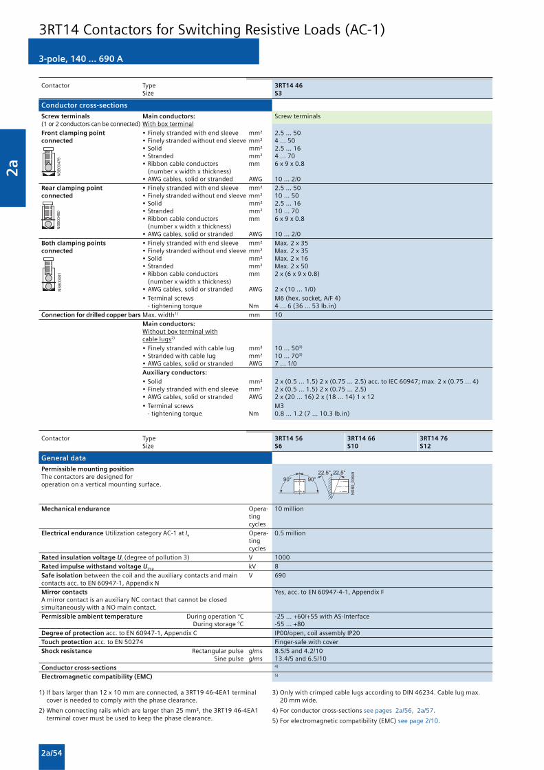
2a
2a/54
��������
�������
������
��������� � � � �
� �
3-pole, 140 ... 690 A
Contactor Type 3RT14 46 Size S3
Conductor cross-sections
Screw terminals Main conductors: Screw terminals(1 or 2 conductors can be connected) With box terminalFront clamping point • Finely stranded with end sleeve mm² 2.5 ... 50connected • Finely stranded without end sleeve mm² 4 ... 50
• Solid mm² 2.5 ... 16• Stranded mm² 4 ... 70• Ribbon cable conductors mm 6 x 9 x 0.8
(number x width x thickness)• AWG cables, solid or stranded AWG 10 ... 2/0
Rear clamping point • Finely stranded with end sleeve mm² 2.5 ... 50connected • Finely stranded without end sleeve mm² 10 ... 50
• Solid mm² 2.5 ... 16• Stranded mm² 10 ... 70• Ribbon cable conductors mm 6 x 9 x 0.8
(number x width x thickness)• AWG cables, solid or stranded AWG 10 ... 2/0
Both clamping points • Finely stranded with end sleeve mm² Max. 2 x 35connected • Finely stranded without end sleeve mm² Max. 2 x 35
• Solid mm² Max. 2 x 16• Stranded mm² Max. 2 x 50• Ribbon cable conductors mm 2 x (6 x 9 x 0.8)
(number x width x thickness)• AWG cables, solid or stranded AWG 2 x (10 ... 1/0)
• Terminal screws M6 (hex. socket, A/F 4) - tightening torque Nm 4 ... 6 (36 ... 53 lb.in)
Connection for drilled copper bars Max. width1) mm 10 Main conductors:
Without box terminal withcable lugs2)
• Finely stranded with cable lug mm² 10 ... 503)
• Stranded with cable lug mm² 10 ... 703)
• AWG cables, solid or stranded AWG 7 ... 1/0 Auxiliary conductors:
• Solid mm² 2 x (0.5 ... 1.5) 2 x (0.75 ... 2.5) acc. to IEC 60947; max. 2 x (0.75 ... 4) • Finely stranded with end sleeve mm² 2 x (0.5 ... 1.5) 2 x (0.75 ... 2.5) • AWG cables, solid or stranded AWG 2 x (20 ... 16) 2 x (18 ... 14) 1 x 12 • Terminal screws M3
- tightening torque Nm 0.8 ... 1.2 (7 ... 10.3 lb.in)
Contactor Type 3RT14 56 3RT14 66 3RT14 76Size S6 S10 S12
General data
Permissible mounting positionThe contactors are designed foroperation on a vertical mounting surface.
Mechanical endurance Opera- 10 million
tingcycles
Electrical endurance Utilization category AC-1 at Ie Opera- 0.5 milliontingcycles
Rated insulation voltage Ui (degree of pollution 3) V 1000Rated impulse withstand voltage Uimp kV 8Safe isolation between the coil and the auxiliary contacts and main V 690contacts acc. to EN 60947-1, Appendix NMirror contacts Yes, acc. to EN 60947-4-1, Appendix FA mirror contact is an auxiliary NC contact that cannot be closedsimultaneously with a NO main contact.Permissible ambient temperature During operation °C -25 ... +60/+55 with AS-Interface
During storage °C -55 ... +80Degree of protection acc. to EN 60947-1, Appendix C IP00/open, coil assembly IP20Touch protection acc. to EN 50274 Finger-safe with coverShock resistance Rectangular pulse g/ms 8.5/5 and 4.2/10
Sine pulse g/ms 13.4/5 and 6.5/10Conductor cross-sections 4)
Electromagnetic compatibility (EMC) 5)
1) If bars larger than 12 x 10 mm are connected, a 3RT19 46-4EA1 terminalcover is needed to comply with the phase clearance.
2) When connecting rails which are larger than 25 mm², the 3RT19 46-4EA1terminal cover must be used to keep the phase clearance.
3) Only with crimped cable lugs according to DIN 46234. Cable lug max.20 mm wide.
4) For conductor cross-sections see pages 2a/56, 2a/57.
5) For electromagnetic compatibility (EMC) see page 2/10.
3RT14 Contactors for Switching Resistive Loads (AC-1)

2a
2a/55
3-pole, 140 ... 690 A
Contactor Type 3RT14 56 3RT14 66 3RT14 76Size S6 S10 S12
Short-circuit protection
Main circuitFuse links gL/gGLV HRC 3NA Type of coordination “1” A 355 500 800Fuse links gR,SITOR 3NE Type of coordination “2” A 350 500 710
Auxiliary circuit
Fuse links gL/gG A 10(weld-free protection at Ik ≥ 1 kA)DIAZED 5SB, NEOZED 5SE
or miniature circuit breakers with C characteristic(short-circuit current Ik < 400 A)
Control
Operating range of the solenoid AC/DC (UC) 0.8 x Us min ... 1.1 x Us max
Power consumption of the solenoid(when coil is cool and rated range Us min ... Us max)
• Conventional operating mechanism
- AC operation Closing at Us min VA/p.f. 250/0.9 490/0.9 700/0.9Closing at Us max VA/p.f. 300/0.9 590/0.9 830/0.9Closed at Us min VA/p.f. 4.8/0.8 5.6/0.9 7.6/0.9Closed at Us max VA/p.f. 5.8/0.8 6.7/0.9 9.2/0.9
- DC operation Closing at Us min W 300 540 770Closing at Us max W 360 650 920Closed at Us min W 4.3 6.1 8.5Closed at Us max W 5.2 7.4 10
Operating times(Total break time = Opening delay + Arcing time)
• Conventional operating mechanism
- with 0.8 x Us min ... 1.1 x Us max Closing delay ms 20 ... 95 30 ... 95 45 ... 100Opening delay ms 40 ... 60 40 ... 80 60 ... 100
- for Us min ... Us max Closing delay ms 25 ... 50 35 ... 50 50 ... 70Opening delay ms 40 ... 60 50 ... 80 70 ... 100
Main circuit
AC capacity
Utilization category AC-1, switching resistive loads
Rated operational currents Ie at 40 °C up to 690 V A 275 400 690at 60 °C up to 690 V A 250 380 6501)
at 1000 V A 100 150 250
Rated power for AC loads2) at 415 V kW 165 250 430P.f. = 0.95 (at 60 °C)
Minimum conductor cross-section for at 40 °C mm² 2 x 70 240 2 x 240loads with Ie at 60 °C mm² 120 240 2 x 240
Power loss per conducting path at Ie/AC-1 W 20 27 55
Utilization category AC-2 and AC-3for an electrical endurance of 1.3 million operating cycles
Rated operational current Ie up to 690 V A 97 138 170
Rated power of slipring or squirrel-cage 230 V kW 30 37 55motors at 50 Hz and 60 Hz(at 60 °C) at 415 V kW 55 75 90
500 V kW 55 90 110690 V kW 90 132 160
DC capacity
Utilization category DC-1, switching resistive loads (L/R ≤ 1 ms)Rated operational currents Ie (at 60 °C)
• 1 conducting path up to 24 V A 250 380 500110 V A 18 33 33
220 V A 3.4 3.8 3.8440 V A 0.8 0.9 0.9
• 2 conducting paths in series up to 24 V A 250 380 500110 V A 250 380 500
220 V A 20 380 500440 V A 3.2 4 4
• 3 conducting paths in series up to 24 V A 250 380 500110 V A 250 380 500
220 V A 250 380 500440 V A 11.5 11 11
1) 600 A for 3RT14 76-N contactor.
2) Industrial furnaces and electric heaters with resistance heating, etc.(increased power consumption on heating up taken into account).
3RT14 Contactors for Switching Resistive Loads (AC-1)

2a
2a/56
��������
�������
������
��������
�������
������
3-pole, 140 ... 690 A
Contactor Type 3RT14 56 3RT14 66 3RT14 76Size S6 S10 S12
Main circuit
DC capacity
Utilization category DC-3 and DC-5Shunt-wound and series-wound motors (L/R ≤ 15 ms)Rated operational currents Ie (at 60 °C)
• 1 conducting path up to 24 V A 250 380 500110 V A 2.5 3 3
220 V A 0.6 0.6 0.6440 V A 0.17 0.18 0.18
• 2 conducting paths in series up to 24 V A 250 380 500110 V A 250 380 500
220 V A 2.5 2.5 2.5440 V A 0.65 0.65 0.65
• 3 conducting paths in series up to 24 V A 250 380 500110 V A 250 380 500
220 V A 250 380 500440 V A 1.4 1.4 1.4
Switching frequency
Switching frequency z in operating cycles/hour
Contactors without overload relays No-load switching frequency h-1 2000AC-1 h-1 600AC-3 h-1 1000
Dependence of the switching frequencyz’ on the operational current I’ and operational voltage U’:z’ = z ·(Ie/I’) ·(400 V/U’)1.5 ·1/h
Contactor Type 3RT14 56 Size S6
Conductor cross-sections
Screw terminals Main conductors: Screw terminalsWith 3RT19 55-4G box terminal
Front or rear clamping point • Finely stranded with end sleeve mm2 16 ... 70connected • Finely stranded without end sleeve mm2 16 ... 70
• Stranded mm2 16 ... 70• Ribbon cable conductors mm 3 x 9 x 0.8 ... 6 x 15.5 x 0.8
(number x width x thickness)• AWG cables, AWG 6 ... 2/0
solid or stranded
Both clamping points • Finely stranded with end sleeves, mm2 1 x 50, 1 x 70connected max.
• Finely stranded without end sleeve mm2 1 x 50, 1 x 70• Stranded (max.) mm2 2 x 70• Ribbon cable conductors mm 2 x (6 x 15.5 x 0.8)
(number x width x thickness), max.• AWG cables, AWG 2 x 1/0
solid or stranded, max.
Front or rear clamping point Main conductorconnected With 3RT19 56-4G box terminal
• Finely stranded with end sleeve mm2 16 ... 120• Finely stranded without end sleeve mm2 16 ... 120• Stranded mm2 16 ... 120• Ribbon cable conductors mm 3 x 9 x 0.8 ... 10 x 15.5 x 0.8
(number x width x thickness)• AWG cables, AWG 6 ... 250 kcmil
solid or stranded
Both clamping points • Finely stranded with end sleeves, mm2 1 x 95, 1 x 120connected max.
• Finely stranded without end sleeve mm2 1 x 95, 1 x 120• Stranded (max.) mm2 2 x 120• Ribbon cable conductors mm 2 x (10 x 15.5 x 0.8)
(number x width x thickness), max.• AWG cables, AWG 2 x 3/0
solid or stranded, max.
• Terminal screws M10 (hexagon socket, A/F4)- tightening torque Nm 10 ... 12 (90 ... 110 lb.in)
3RT14 Contactors for Switching Resistive Loads (AC-1)

2a
2a/57
��������
�������
������
3-pole, 140 ... 690 A
Contactor Type 3RT14 56 Size S6
Conductor cross-sections
Screw terminals Main conductors:Without box terminal/busbar connection1)
• Finely stranded with cable lug 16 ... 95• Stranded with cable lug 25 ... 120• AWG cables, solid or stranded 4 ... 250 kcmil• Connecting bar (max. width) 17
• Terminal screw M8 x 25 (A/F 13)- tightening torque Nm 10 ... 14 (90 ... 110) lb.in
Auxiliary conductors:
• Conductor cross-section - solid 2 x (0.5 ... 1.5)2); 2 x (0.75 ... 2.5)2) acc. to IEC 60947; max. 2 x (0.75 ... 4)- finely stranded with end sleeve 2 x (0.5 ... 1.5)2); 2 x (0.75 ... 2.5)2)
- solid or stranded AWG (2 x) 2 x (18 ... 14)
• Terminal screw M3 (PZ 2)- tightening torque Nm 0.8 ... 1.2 (7 ... 10.3) lb.in
Contactor Type 3RT14 66 3RT14 76 Size S10 S12
Conductor cross-sections
Screw terminals Main conductors: Screw terminals(1 or 2 conductors can be With 3RT19 66-4G box terminalconnected)
Front clamping point • Finely stranded with end sleeve mm² 70 ... 240connected • Finely stranded without end sleeve mm² 70 ... 240
• Stranded mm² 95 ... 300• AWG cables, solid or stranded AWG 3/0 ... 600 kcmil• Ribbon cable conductors mm Min. 6 x 9 x 0.8, max. 20 x 24 x 0.5
(number x width x thickness)
Rear clamping point • Finely stranded with end sleeve mm² 120 ... 185connected • Finely stranded without end sleeve mm² 120 ... 185
• Stranded mm² 120 ... 240• AWG cables, solid or stranded AWG 250 ... 500 kcmil• Ribbon cable conductors mm Min. 6 x 9 x 0.8, max. 20 x 24 x 0.5
(number x width x thickness)
Both clamping points • Finely stranded with end sleeve mm² Min. 2 x 50, max. 2 x 185connected • Finely stranded without end sleeve mm² Min. 2 x 50, max. 2 x 185
• Stranded mm² Min. 2 x 70, max. 2 x 240• AWG cables, solid or stranded AWG Min. 2 x 2/0, max. 2 x 500 kcmil• Ribbon cable conductors mm Max. 2 x (20 x 24 x 0.5)
(number x width x thickness)
• Terminal screws M12 (hexagon socket, A/F 5) - tightening torque Nm 20 ... 22 (180 ... 195 lb.in)
Screw terminals Main conductors:Without box terminal/busbar connection 3)
• Finely stranded with cable lug mm² 50 ... 240 • Stranded with cable lug mm² 70 ... 240 • AWG cables, solid or stranded AWG 2/0 ... 500 kcmil • Connecting bar (max. width) mm 25
• Terminal screws M10 x 30 (A/F 17) - tightening torque Nm 14 ... 24 (124 ... 210 lb.in)
Auxiliary conductors:
• Solid mm² 2 x (0.5 ... 1.5)4), 2 x (0.75 ... 2.5)4) acc. to IEC 60947, max. 2 x (0.75 ... 4) • Finely stranded with end sleeve mm² 2 x (0.5 ... 1.5)4); 2 x (0.75 ... 2.5)4)
• AWG cables, solid or stranded AWG 2 x (18 ... 14)
• Terminal screws M3 (PZ 3) - tightening torque Nm 0.8 ... 1.2 (7 ... 10.3 lb.in)
1) When connecting cable lugs according to DIN 46235, use the 3RT19 56-4EA1 terminal cover for conductor cross-sections from 95 mm2 to ensurephase spacing.
2) If two different conductor cross-sections are connected to one clampingpoint, both cross-sections must lie in the range specified. If identicalcross-sections are used, this restriction does not apply.
3) When connecting cable lugs to DIN 46234, the 3RT19 66-4EA1 terminalcover must be used for conductor cross-sections of 240 mm² and more aswell as DIN 46235 for conductor cross-sections of 185 mm² and more tokeep the phase clearance.
4) If two different conductor cross-sections are connected to one clampingpoint, both cross-sections must lie in the range specified. If identicalcross-sections are used, this restriction does not apply.
3RT14 Contactors for Switching Resistive Loads (AC-1)

2a
2a/58
4-pole, 4 NO, 18 ... 140 A
Overview
AC and DC operation
EN 60947-4-1 (VDE 0660 Part 102).
The contactors are suitable for use in any climate. They arefinger-safe according to EN 50274.
The accessories for the 3-pole SIRIUS contactors can also beused for the 4-pole versions.
Function
• Switching resistive loads
• Isolating systems with ungrounded or poorly groundedneutral conductors
• System transfers when alternative AC power supplies areused
• As contactors, e.g. for variable-speed operating mechanismswhich only have to carry current and not switch
Integration
Mountable auxiliary contacts
Size S00
4 auxiliary contacts (according to EN 50005)
Size S0
Maximum 2 auxiliary contacts (either laterally mounted orsnapped onto the top).
Size S2 to S3
Max. 4 auxiliary contacts (either laterally mounted or snappedonto the top)
Contactor assembly with mechanical interlock
The 4-pole 3RT13 contactors with 4 NO contacts as the maincontacts are suitable for making contactor assemblies with amechanical interlock, e.g. for system transfers.
Size S00
Contactor assemblies can be constructed from two 3RT13 1 .contactors in conjunction with mechanical interlocks andtwo connecting clips (Order No.: 3RA19 12-2H, pack with10 interlock elements and 20 clips for 10 assemblies).
Size S0
When constructing 4-pole contactor assemblies fromtwo 3RT13 2 . contactors, the fourth pole of the left contactormust always be moved to the left side. The contactor assemblycan then be made easily with the aid of the 3RA19 24-1A
mechanical interlock fitted onto the front and the 3RA19 22-2Cmechanical connectors. The laterally mountable 3RA19 24-2Bmechanical interlock can be used if the contactor assembly ismounted on a base plate.
Sizes S2 and S3
Contactor assemblies can be constructed from two 3RT13 3 .or two 3RT13 4 . contactors in conjunction with the laterallymountable 3RA19 24-2B mechanical interlock and the3RA19 .2-2G mechanical connectors. The mechanical interlockfor fitting onto the front cannot be used for size S2 and S3contactors.
3RT13 Contactors for Switching Resistive Loads (AC-1)

2a
2a/59
Technical specifications
4-pole, 4 NO, 18 ... 140 A
3RT13 Contactors for Switching Resistive Loads (AC-1)
1) In accordance with the corresponding 3-pole 3RT1 contactors.
2) With size S00, DC operation: Operating times at 0.85 ... 1.1 x Us.
Contactor Type 3RT13 16 3RT13 17 3RT13 25 3RT13 26 3RT13 36 3RT13 44 3RT13 46 Size S00 S0 S2 S3 S3
General data
Permissible mounting position1)
Mechanical endurance Opera- 30 million 10 milliontingcycles
Electrical endurance at Ie/AC-1 Opera- Approx. 0.5 milliontingcycles
Rated insulation voltage Ui (degree of pollution 3) V 690
Permissible ambient During operation °C -25 ... +60temperature During storage °C -55 ... +80
Degree of protection Device IP20 IP20Acc. to EN 60947-1, Appendix C Connection range IP00
Touch protection acc. to EN 50274 Finger-safe
Short-circuit protection of contactors without overload relays
Main circuitFuse links, Type of coordination “1”1) A 35 63 160 250 250gL/gG operational class Type of coordination “2”1) A 20 25/35 63 125 160LV HRC, 3NA, DIAZED, 5SB,NEOZED, 5SE
- acc. to IEC 60947-4-1/ Weld-free A 10 16 50 63 100EN 60947-4-1
Control
Magnetic coil operating range
AC at 50 Hz 0.8 ... 1.1 x Us AC at 60 Hz 0.85 ...1.1 x Us
DC at 50 °C 0.8 ... 1.1 x Us DC at 60 °C 0.85 ... 1.1 x Us
AC/DC 0.8 ... 1.1 x Us
Power consumption of the magnetic coils (when coil is cold and 1.0 x Us)
AC operation, 50 Hz • Closing VA 61 145 270 • P.f. VA 0.82 0.79 0.68
• Closed VA 7.8 12.5 22 • P.f. VA 0.24 0.36 0.27
AC operation, 50/60 Hz • Closing VA 26.5/24.3 64/63 170/155 298/274 • P.f. 0.79/0.75 0.82/0.74 0.76/0.72 0.72/0.62
• Closed VA 4.4/3.4 8.4/6.8 15/11.8 27/20 • P.f. 0.27/0.27 0.24/0.28 0.35/0.38 0.29/0.31
DC operation • Closing W 3.3 5.6 13.3 15= Closed
Operating times for 0.8 ... 1.1 x Us2)
Total break time = Opening delay + Arcing time
• DC operation Closing delay ms 25 ... 100 30 ... 90 50 ... 110 110 ... 200Opening delay ms 7 ... 10 13 ... 40 15 ... 30 14 ... 20
• AC operation Closing delay ms 8 ... 35 6 ... 30 4 ... 35 20 ... 50Opening delay ms 4 ... 30 13 ... 25 10 ... 30 10 ... 25
• Arcing time ms 10 ... 15 10 ... 15 10 ... 15 10 ... 15
Main circuit
AC capacity
Utilization category AC-1, switching resistive loads
Rated operational currents Ie at 40 °C, up to 690 V A 18 22 35 40 60 110 140at 60 °C, up to 690 V A 16 20 30 35 55 100 120
Rated power for AC loadsP.f. = 0.95 (at 40 °C) at 415 V kW 12 14.5 22 26 39 72 92
Minimum conductor cross-section for loads with Ie at 40/60 °C mm² 2.5 2.5 10 10 16 50 50
Utilization category AC-2 and AC-3
Rated operational currents Ie at 60°C, up to 400 V A 9 12 17 25 26 — —
Rated power of slipring or squirrel-cage at 230 V kW 3 3 4 5.5 5.5 — —motors at 50 Hz and 60 Hz 415 V kW 4 5.5 7.5 11 11 — —

2a
2a/60
4-pole, 4 NO, 18 ... 140 A
Contactor Type 3RT13 16 3RT13 17 3RT13 25 3RT13 26 Size S00 S0
Main circuit
DC capacity
Utilization category DC-1, switching resistive loads (L/R ≤ 1ms)
Rated operational currents Ie (at 40 °C)
• 1 conducting path up to 24 V A 18 22 35110 V A 2.1 2.1 4.5
220 V A 0.8 0.8 1440 V A 0.6 0.6 0.4
• 2 conducting paths in series up to 24 V A 18 22 35110 V A 12 12 35
220 V A 1.6 1.6 5440 V A 0.8 0.8 1
• 3 conducting paths in series up to 24 V A 18 22 35110 V A 18 22 35
220 V A 18 22 35440 V A 1.3 1.3 2.9
• 4 conducting paths in series up to 24 V A 18 22 35110 V A 18 22 35
220 V A 18 22 35440 V A 1.3 1.3 2.9
3RT13 Contactors for Switching Resistive Loads (AC-1)

2a
2a/61
4-pole, 4 NO, 18 ... 140 A
Contactor Type 3RT13 16 3RT13 17 3RT13 25 3RT13 26 Size S00 S0
Main circuit
DC capacity
Utilization category DC-3/DC-5Shunt-wound and series-wound motors (L/R ≤ 15 ms)
Rated operational currents Ie (at 40 °C)
• 1 conducting path up to 24 V A 18 20 20110 V A 0.15 0.15 2.5
220 V A — — 1440 V A — — 0.09
• 2 conducting paths in series up to 24 V A 18 20 35110 V A 0.35 0.35 15
220 V A — — 3440 V A — — 0.27
• 3 conducting paths in series up to 24 V A 18 20 35110 V A 18 20 35
220 V A 1.5 1.5 10440 V A 0.2 0.2 0.6
• 4 conducting paths in series up to 24 V A 18 20 35110 V A 18 20 35
220 V A 1.5 1.5 35440 V A 0.2 0.2 0.6
Maximum breaking current AC
e.g. for isolation of load distributions
• 50/60 Hz 415 V A 72 96 200
Contactor Type 3RT13 36 3RT13 44 3RT13 46Size S2 S3 S3
Main circuit
DC capacity
Utilization category DC-1, switching resistive loads (L/R ≤ 1ms) Rated operational currents Ie (at 40 °C) • 1 conducting path up to 24 V A 50 70 80
110 V A 4.5 4.5 9220 V A 1 1 2440 V A 0.4 0.4 0.6
• 2 conducting paths in series up to 24 V A 50 70 80110 V A 45 70 80220 V A 5 5 10440 V A 1 1 1.8
• 3 conducting paths in series up to 24 V A 50 70 80110 V A 45 70 80220 V A 45 70 80440 V A 2.9 2.9 4.5
• 4 conducting paths in series up to 24 V A 50 70 80110 V A 45 70 80220 V A 45 70 80440 V A 2.9 2.9 4.5
Utilization category DC-3/DC-5Shunt-wound and series-wound motors (L/R ≤ 15 ms)Rated operational currents Ie (at 40 °C) • 1 conducting path up to 24 V A 20 20 20
110 V A 2.5 2.5 2.5220 V A 1 1 1440 V A 0.1 0.15 0.15
• 2 conducting paths in series up to 24 V A 45 70 80110 V A 25 70 80220 V A 5 7 7440 V A 0.27 0.42 0.42
• 3 conducting paths in series up to 24 V A 45 70 80110 V A 45 70 80220 V A 25 35 35440 V A 0.6 0.8 0.8
• 4 conducting paths in series up to 24 V A 45 70 80110 V A 45 70 80220 V A 45 70 80440 V A 0.6 0.8 0.8
Maximum breaking current ACe.g. for isolation of load distributions• 50/60 Hz 415 V A 400 520 760
3RT13 Contactors for Switching Resistive Loads (AC-1)

2a
2a/62
4-pole, 4 NO, 200 ... 1000 A
Overview
EN 60947-4-1 (VDE 0660 Part 102)
The contactors also comply with the requirements ofNFC 63-110 and NFC 20–040.
The contactors are suitable for use in any climate. They arefinger-safe according to EN 50274. Terminal covers may haveto be fitted onto the connecting bars, depending on theconfiguration with other devices.
Magnetic coils for 3TK10 to 3TK13 contactors: as withdrawablecoils.
Surge suppression
Control circuit
Magnetic coils for 3TK1 contactors: can be retrofitted with RCelements.
Function
• Isolating systems with ungrounded or poorly groundedneutral conductors
• Switching resistive loads
• System transfers when alternative AC power supplies areused
Technical specifications
Contactor Type 3TK1
Rated data of the auxiliary contacts Acc. to IEC 60947-5-1 (VDE 0660 Part 200)
Rated insulation voltage Ui V 690(degree of pollution 3)
Continuous thermal current Ith = A 10Rated operational current Ie/AC-12
AC loadRated operational current Ie/AC-15/AC-14for rated operational voltage Ue
24 V A 6 110 V A 6 125 V A 6
220 V A 6 230 V A 6 380 V A 4
415 V A 4 500 V A 1 660 V A 1 690 V A 1
DC loadRated operational current Ie/DC-12for rated operational voltage Ue
24 V A — 60 V A — 110 V A —
125 V A — 220 V A — 440 V A — 600 V A —
Rated operational current Ie/DC-13 for rated operational voltage Ue
24 V A 6 60 V A 6 110 V A 1.8
125 V A — 220 V A 0.6
440 V A — 600 V A —
CSA and UL rated data for the auxiliary contacts
Rated voltage V AC, 600max.
Switching capacity A 600, P 600
3TK1 Contactors for Switching Resistive Loads (AC-1)

2a
2a/63
4-pole, 4 NO, 200 ... 1000 A
��������� � � � �
� �
1) Dependence of the switching frequency z ’ on the operational current I ’and operational voltage U ’ : z ’ = z · (Ie/I ’) · (400 V/U ’)1.5 · 1/h.
Contactor Type 3TK10 3TK11 3TK12 3TK13 3TK14 3TK15 3TK17
General data
Permissible mounting positionVertical mounting position also permitted.
Mechanical endurance Operating cycles Mill. 10 5
Electrical endurance Operating cycles Mill. 0.8 0.8 0.8 0.4 0.65 0.5 0.4for Ie/AC-1 at 55 °C
Rated insulation voltage Ui (degree of pollution 3) V 1000
Ambient temperature During operation °C -25 ... +55 During storage °C -50 ... +70
Degree of protection acc. to EN 60947-1, Appendix C IP00
Touch protection acc. to EN 50274 Finger-safe with cover
Shock resistance Sine pulse g/ms 10/15
Short-circuit protection
Main circuitFuse links, gL/gG, LV HRC 3NA, DIAZED 5SB, NEOZED 5SE
- acc. to IEC 60947-4-1/ Type of coordination “1” A 250 355 800 1000EN 60947-4-1 Type of coordination “2” A 250 315 630 850
Auxiliary circuit(short-circuit current Ik ≥ 1 kA) fuse links, gL/gG, A 10DIAZED 5SB, NEOZED 5SE
Control
Magnetic coil operating range 0.85 ... 1.1 x Us
Power consumption of the magnetic coils (when coil is cold and 1.0 x Us)
50 Hz Closing VA 820 1100 3500 P.f. 0.4 0.35 0.26
Closed VA 44 52 125 P.f. 0.34 0.35 0.4
60 Hz Closing VA 990 1200 4000 P.f. 0.35 0.31 0.22
Closed VA 52 65 140 P.f. 0.35 0.34 0.43
Operating times at 1.0 x Us
Closing delay ms 20 ... 40 30 ... 60 Opening delay ms 7 ... 15 10 ... 20
Arcing time ms 10 10
Main circuit
AC capacityUtilization category AC-1, switching resistive loads
Rated operational currents Ie at 40 °C up to 690 V A 200 250 300 350 550 800 1000 at 50 °C up to 690 V A 180 230 270 310 470 650 850
Rated power for AC loads, p.f. = 0.95 at 230 V kW 76 95 114 132 208 303 378(at 40°C) 400 V kW 132 165 197 230 362 527 658
500 V kW 165 206 247 288 452 658 828690 V kW 227 284 341 397 624 908 1135
Minimum conductor cross-sections for loads with Ie at 40° C mm² 95 150 185 240 185 240 300
Utilization category AC-2 and AC-3
Rated operational currents Ie up to 400 V A 120 145 210 210 400 550 700Rated power of squirrel-cage at 230 V kW 30 45 75 75 110 160 220or slipring motors at 50 Hz and 60 Hz 400 V kW 55 75 110 110 200 280 370Short-time current at 40° C in cold state up to 10 s A 900 1200 1600 1600 5300 5300 6400
Switching frequency1)
Switching frequency z in operating cycles/hour
Contactors without No-load switching frequency 1/h 3600overload relays AC-1 1/h 300
AC-3 1/h 300
Conductor cross-sections
Main conductors: Screw terminals
• Stranded with cable lug mm2 2 x 70 2 x 120 2 x 120 2 x 300• Solid or stranded AWG MCM 2 x 00 2 x 250 2 x 250 2 x 600• Connecting bar (max. width) mm 30 30 33 55• Terminal screw M6 M10 M10 M10
- tightening torque Nm 5 16 16 16lb.in 42 135 135 135
Auxiliary conductors:
• Solid mm2 2 x (0.5 ... 2.5)• Finely stranded with end sleeve mm2 2 x (0.5 ... 2.5)• Solid or stranded AWG MCM 20 ... 14
- tightening torque Nm 1.2 (10 lb.in)
3TK1 Contactors for Switching Resistive Loads (AC-1)

2a
2a/64
4-pole, 2 NO + 2 NC, 4 ... 18.5 kW
3RT15 Contactors for Special Applications
Overview
AC and DC operation
EN 60947-4-1 (VDE 0660 Part 102).
The contactors are suitable for use in any climate. They arefinger-safe according to EN 50274.
The accessories for the 3-pole SIRIUS contactors can also beused for the 4-pole versions.
Function
Integration
Technical specifications
• Changing the polarity of hoisting gear motors
• Switching two separate loads
Note:
3RT15 contactors are not suitable for switching a loadbetween two current sources.
Mountable auxiliary contacts
Size S00
4 auxiliary contacts (auxiliary switch blocks)
Size S0
Maximum 2 auxiliary contacts (either laterally mounted orsnapped onto the top auxiliary switch blocks).
Size S2
Maximum 4 auxiliary contacts (either laterally mounted orsnapped onto the top auxiliary switch blocks).
1) In accordance with the corresponding 3-pole 3RT1 contactors. 2) With size S00, DC operation: Operating times at 0.85 ... 1.1 x Us.
Contactor Type 3RT15 16 3RT15 17 3RT15 26 3RT15 35 Size S00 S00 S0 S2
General data
Permissible mounting position1)
Mechanical endurance Opera- 30 million 10 milliontingcycles
Electrical endurance at Ie/AC-1 Opera- Approx. 0.5 milliontingcycles
Rated insulation voltage Ui (degree of pollution 3) V 690
Permissible ambient temperature During operation °C -25 ... +60During storage °C -55 ... +80
Degree of protection acc. to EN 60947-1, Appendix C IP20 IP20 (IP00 terminal compartment)
Touch protection acc. to EN 50274 Finger-safe
Short-circuit protection of contactors without overload relays
Main circuit
Fuse links, gL/gG Type of coordination “1” A 35 63 160LV HRC 3NA, DIAZED 5SB, Type of coordination “2” A 20 35 80NEOZED 5SE Weld-free A 10 16 50
- acc. to IEC 60947-4-1/EN60947-4-1
Control
Magnetic coil operating range
AC at 50 Hz 0.8 ... 1.1 x Us AC at 60 Hz 0.85 ... 1.1 x Us DC at 50 °C 0.8 ... 1.1 x Us DC at 60 °C 0.85 ... 1.1 x Us
AC/DC 0.8 ... 1.1 x Us
Power consumption of the magnetic coils (when coil is cold and 1.0 x Us)
AC operation, 50 Hz Closing VA 61 145 P.f. VA 0.82 0.79
Closed VA 7.8 12.5P.f. VA 0.24 0.36
AC operation, 50/60 Hz Closing VA 26.5/24.3 64/63 170/155 P.f. VA 0.79/0.75 0.82/0.74 0.76/0.72
Closed VA 4.4/3.4 8.4/6.8 15/11.8 P.f. VA 0.27/0.27 0.24/0.28 0.35/0.38
DC operation Closing = Closed W 3.3 5.6 13.3
Operating times for 0.8 ... 1.1 x Us2)
Total break time = Opening delay + Arcing time
AC/DC operation
• DC operation Closing delay ms 25 ... 100 30 ... 90 50 ... 110Opening delay ms 7 ... 10 13 ... 40 15 ... 30
• AC operation Closing delay ms 8 ... 35 6 ... 30 4 ... 35Opening delay ms 4 ... 30 13 ... 25 10 ... 30
• Arcing time ms 10 ... 15

2a
2a/65
4-pole, 2 NO + 2 NC, 4 ... 18.5 kW
3RT15 Contactors for Special Applications
Contactor Type 3RT15 16 3RT15 17 3RT15 26 3RT15 35 Size S00 S00 S0 S2
Main circuit
AC capacity
Utilization category AC-1, switching resistive loads
Rated operational currents Ie at 40 °C up to 690 V A 18 22 40 60at 60 °C up to 690 V A 16 20 35 55
Rated power for AC loads at 415 V kW 11 13 26 36P.f. = 0.95 (at 60 °C)
Minimum conductor cross-section at 40 °C mm² 2.5 2.5 10 16for loads with Ie
Utilization category AC-2 and AC-3
Rated operational currents Ie up to 415 V A 9 12 25 1) 40(at 60 °C)
Rated power of slipring or at 230 V kW 3 3 5.5 9.5squirrel-cage motors at 50 and 60 Hz 415 V kW 4 5.5 11 18.5
DC capacity
Utilization category DC-1, switching resistive load (L/R ≤ 1 ms)Rated operational currents Ie (at 60 °C)
• 1 conducting path up to 24 V A 16 20 35 50 110 V A 2.1 2.1 4.5 4.5 220 V A 0.8 0.8 1 1 440 V A 0.6 0.6 0.4 0.4
• 2 conducting paths in series up to 24 V A 16 20 35 50 110 V A 12 12 35 45 220 V A 1.6 1.6 5 5 440 V A 0.8 0.8 1 1
Utilization category DC-3/DC-52),shunt-wound and series-wound motors (L/R ≤ 15 ms)Rated operational currents Ie (at 60 °C)
• 1 conducting path up to 24 V A 16 20 20 35 110 V A 0.15 0.15 2.5 2.5 220 V A 0.75 0.75 1 1 440 V A — — 0.09 0.1
• 2 conducting paths in series up to 24 V A 16 20 35 50 110 V A 0.35 0.35 15 25 220 V A — — 3 5 440 V A — — 0.27 0.27
1) For AC operation: 25 ADC operation: 20 A.
2) For Us >24 V the rated operational currents Ie for the NC contactconducting paths are 50 % of the values for the NO contact conductingpaths.
Contactor Type 3RT15 16 3RT15 17 3RT15 26 3RT15 35 Size S00 S00 S0 S2
Main circuit
AC capacity
Utilization category AC-1, switching resistive loads
Rated operational currents Ie at 40 °C up to 690 V A 18 22 40 60at 60 °C up to 690 V A 16 20 35 55
Rated power for AC loads at 415 V kW 11 13 26 36P.f. = 0.95 (at 60 °C)
Minimum conductor cross-section at 40 °C mm² 2.5 2.5 10 16for loads with Ie
Utilization category AC-2 and AC-3
Rated operational currents Ie up to 415 V A 9 12 25 1) 40(at 60 °C)
Rated power of slipring or at 230 V kW 3 3 5.5 9.5squirrel-cage motors at 50 and 60 Hz 415 V kW 4 5.5 11 18.5
DC capacity
Utilization category DC-1, switching resistive load (L/R ≤ 1 ms)Rated operational currents Ie (at 60 °C)
• 1 conducting path up to 24 V A 16 20 35 50 110 V A 2.1 2.1 4.5 4.5 220 V A 0.8 0.8 1 1 440 V A 0.6 0.6 0.4 0.4
• 2 conducting paths in series up to 24 V A 16 20 35 50 110 V A 12 12 35 45 220 V A 1.6 1.6 5 5 440 V A 0.8 0.8 1 1
Utilization category DC-3/DC-52),shunt-wound and series-wound motors (L/R ≤ 15 ms)Rated operational currents Ie (at 60 °C)
• 1 conducting path up to 24 V A 16 20 20 35 110 V A 0.15 0.15 2.5 2.5 220 V A 0.75 0.75 1 1 440 V A — — 0.09 0.1
• 2 conducting paths in series up to 24 V A 16 20 35 50 110 V A 0.35 0.35 15 25 220 V A — — 3 5 440 V A — — 0.27 0.27

2a
2a/66
12.5 ... 50 kvar
3RT16 Contactors for Special Applications
Overview
AC operation
IEC 60947, EN 60947 (VDE 0660)
The contactors are suitable for use in any climate. They are
finger-safe according to EN 50274.
The 3RT16 capacitor contactors are special version of the sizeS00 to S3 SIRIUS contactors. The capacitors are precharged bymeans of the mounted leading NO contacts and resistors; onlythen do the main contacts close.
This prevents disturbances in the network and welding of thecontactors.
Only discharged capacitors are permitted to be switched onwith capacitor contactors.
The auxiliary switch block which is snapped onto the capacitorcontactor contains the three leading NO contacts and in thecase of S00 one standard NC contact and in the case of S0 andS3 one standard NO contact, which is unassigned. Size S00also contains another unassigned NO contact in the basic unit.
In addition, a 2-pole auxiliary switch block can be mountedlaterally on the 3RT16 47 capacitor contactors (2 NO, 2 NC or1 NO + 1 NC versions); type 3RH19 21-1EA . . . The fitting ofauxiliary switches for 3RT16 17 and 3RT16 27 is notexpandable.
For the capacitor switching capacity of the basic 3RT10contactor version, see Technical specifications.
Technical specifications
All technical specifications not mentioned in the table below are identical to those of the 3RT10 17 contactors for size S00, tothose of the 3RT10 26 contactors for size S0 and to those of the 3RT10 45 contactors for size S3.
Contactor Type 3RT16 17- . A . . 3 3RT16 27- . A . . 1 3RT16 47- . A . . 1Size S00 S0 S3
Capacitor rating at 230 V, 50/60 Hz kvar 3 … 7.5 3.5 … 15 3.5 … 30rated power 415 V, 50/60 Hz kvar 5 … 12.5 6 … 25 5 … 50(utilization category AC-6b) 525 V, 50/60 Hz kvar 7.5 … 15 7.8 … 30 7.5 … 60
690 V, 50/60 Hz kvar 10 … 21 10 … 42 10 … 84
Auxiliary contacts mounted (unassigned) 1 NO + 1 NC 1 NO
Auxiliary contacts mountable (lateral), not for sizes S00 and S0 — 2 NC + 2 NO or1 NO + 1 NC
Magnetic coil operating range 0.8 … 1.1 x Us
Max. switching frequency h-1 180 100
Electrical endurance Opera- > 250000 > 150000 > 100000tingcycles
Ambient temperature °C 60
Standards IEC 60947/EN 60947 (VDE 0660)
Short-circuit protection 1.6 ... 2.2 x Ie
Conductor cross-sections
Screw terminals Main conductors Screw terminals(1 or 2 conductors can be • Solid mm² 2 x (0.5 ... 1.5); 2 x (1 ... 2.5);connected) 2 x (0.75 ... 2.5) 2 x (2.5 ... 6)
Acc. to IEC 60947; Acc. to IEC 60947;Max. 2 x (1 ... 4) Max. 1 x 101)
• Finely stranded with end sleeve mm² 2 x (0.5 ... 1.5); 2 x (1 ... 2.5);2 x (0.75 ... 2.5) 2 x (2.5 ... 6) 1)
• AWG cables- solid AWG 2 x (20 ... 16) 2 x (16 ... 12)- solid or stranded AWG 2 x (18 ... 14) 2 x (14 ... 10)- stranded AWG 1 x 12 1 x 8
• Terminal screws M3 M4 (Pozidriv size 2)- tightening torque Nm 0.8 ... 1.2 2 ... 2.5
lb.in 7 ... 10.3 18 ... 22
1) 3RV19 25-5AB feeder terminal for 16 mm2.
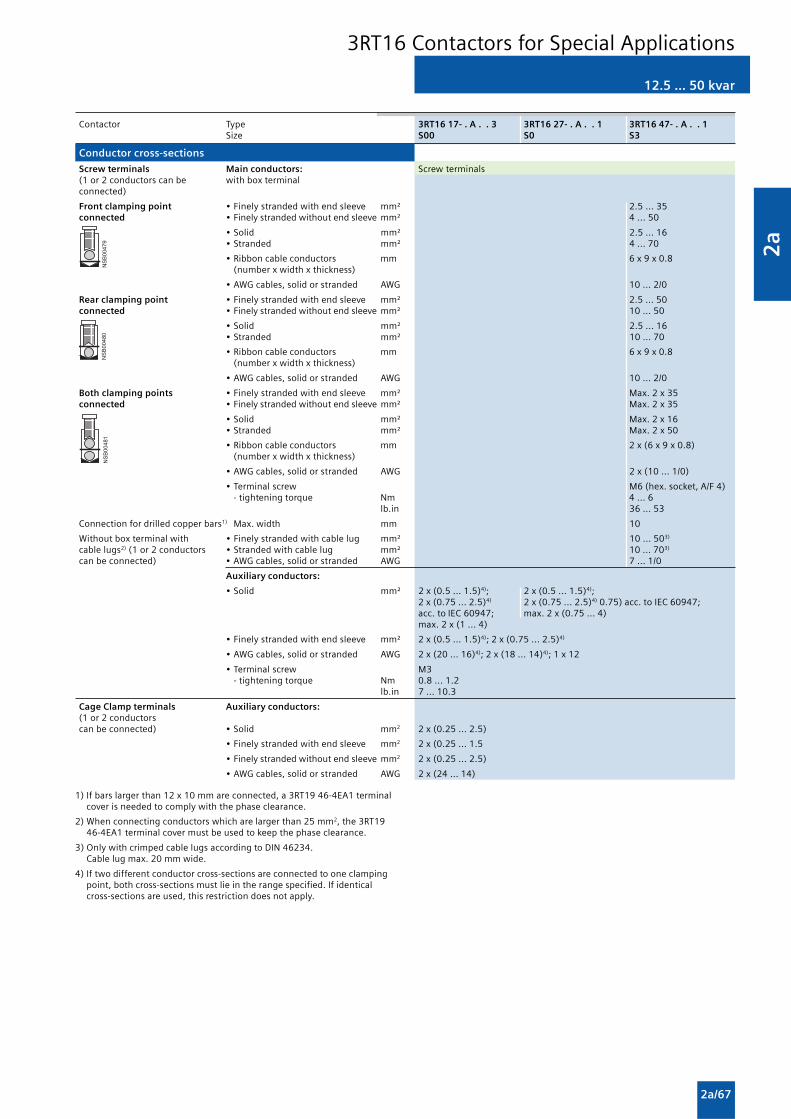
2a
2a/67
12.5 ... 50 kvar
3RT16 Contactors for Special Applications
1) If bars larger than 12 x 10 mm are connected, a 3RT19 46-4EA1 terminalcover is needed to comply with the phase clearance.
2) When connecting conductors which are larger than 25 mm2, the 3RT1946-4EA1 terminal cover must be used to keep the phase clearance.
3) Only with crimped cable lugs according to DIN 46234.Cable lug max. 20 mm wide.
4) If two different conductor cross-sections are connected to one clampingpoint, both cross-sections must lie in the range specified. If identicalcross-sections are used, this restriction does not apply.
��������
�������
������
Contactor Type 3RT16 17- . A . . 3 3RT16 27- . A . . 1 3RT16 47- . A . . 1Size S00 S0 S3
Conductor cross-sections
Screw terminals Main conductors: Screw terminals(1 or 2 conductors can be with box terminal connected)
Front clamping point • Finely stranded with end sleeve mm² 2.5 ... 35connected • Finely stranded without end sleeve mm² 4 ... 50
• Solid mm² 2.5 ... 16• Stranded mm² 4 ... 70
• Ribbon cable conductors mm 6 x 9 x 0.8(number x width x thickness)
• AWG cables, solid or stranded AWG 10 ... 2/0
Rear clamping point • Finely stranded with end sleeve mm² 2.5 ... 50connected • Finely stranded without end sleeve mm² 10 ... 50
• Solid mm² 2.5 ... 16• Stranded mm² 10 ... 70
• Ribbon cable conductors mm 6 x 9 x 0.8(number x width x thickness)
• AWG cables, solid or stranded AWG 10 ... 2/0
Both clamping points • Finely stranded with end sleeve mm² Max. 2 x 35connected • Finely stranded without end sleeve mm² Max. 2 x 35
• Solid mm² Max. 2 x 16• Stranded mm² Max. 2 x 50
• Ribbon cable conductors mm 2 x (6 x 9 x 0.8)(number x width x thickness)
• AWG cables, solid or stranded AWG 2 x (10 ... 1/0)
• Terminal screw M6 (hex. socket, A/F 4) - tightening torque Nm 4 ... 6
lb.in 36 ... 53
Connection for drilled copper bars1) Max. width mm 10
Without box terminal with • Finely stranded with cable lug mm² 10 ... 503)
cable lugs2) (1 or 2 conductors • Stranded with cable lug mm² 10 ... 703)
can be connected) • AWG cables, solid or stranded AWG 7 ... 1/0
Auxiliary conductors:
• Solid mm² 2 x (0.5 ... 1.5)4); 2 x (0.5 ... 1.5)4);2 x (0.75 ... 2.5)4) 2 x (0.75 ... 2.5)4) 0.75) acc. to IEC 60947;acc. to IEC 60947; max. 2 x (0.75 ... 4)max. 2 x (1 ... 4)
• Finely stranded with end sleeve mm² 2 x (0.5 ... 1.5)4); 2 x (0.75 ... 2.5)4)
• AWG cables, solid or stranded AWG 2 x (20 ... 16)4); 2 x (18 ... 14)4); 1 x 12
• Terminal screw M3- tightening torque Nm 0.8 ... 1.2
lb.in 7 ... 10.3
Cage Clamp terminals Auxiliary conductors:(1 or 2 conductorscan be connected) • Solid mm2 2 x (0.25 ... 2.5)
• Finely stranded with end sleeve mm2 2 x (0.25 ... 1.5
• Finely stranded without end sleeve mm2 2 x (0.25 ... 2.5)
• AWG cables, solid or stranded AWG 2 x (24 ... 14)

2a
2a/68
Overview
1- and 2-pole, 32 ... 400 A
3TC4 and 3TC5
EN 60947-4-1 (VDE 0660 Part 102).
The contactors are finger-safe according to EN 50274.
Terminal covers may have to be fitted onto the connectingbars, depending on the configuration with other devices.
The DC motor ratings given in the tables are applicable to theDC-3 and DC-5 utilization categories with two-pole switching ofthe load or with the two conducting paths of the contactorconnected in series.
One contactor conducting path can switch full power up to220 V. The ratings for higher voltages are available on request.
Technical specifications
Contactor Type 3TC4 3TC5
Rated data of the auxiliary contacts
Rated insulation voltage Ui V 690(degree of pollution 3)
Continuous thermal current Ith = 10 10Rated operational current Ie/AC-12
AC loadRated operational current Ie/AC-15/AC-14for rated operational voltage Ue
24 V A 10 10110 V A 10 10125 V A 10 10220 V A 6 6230 V A 5.6 5.6
380 V A 4 4415 V A 3.6 3.6500 V A 2.5 2.5660 V A 2.5 2.5690 V A — —
DC loadRated operational current Ie/DC-12for rated operational voltage Ue
24 V A 10 1060 V A 10 10
110 V A 3.2 8125 V A 2.5 6
220 V A 0.9 2440 V A 0.33 0.6600 V A 0.22 0.4
Rated operational current Ie/DC-13for rated operational voltage Ue
24 V A 10 1060 V A 5 5
110 V A 1.14 2.4125 V A 0.98 2.1
220 V A 0.48 1.1440 V A 0.13 0.32600 V A 0.07 0.21
Contactor Type 3TC44 ... 3TC56
CSA and UL rated data for the auxiliary contacts
Rated voltage V AC, 600max.
Switching capacity A 600, P 600
3TC Contactors for Switching DC Voltage

2a
2a/69
1- and 2-pole, 32 ... 400 A
Contactor Type 3TC44 ... 3TC56
Endurance of the main contacts
Legend for the diagrams:Ia = Breaking current
1) See the endurance diagram above.
2) For 3TC44, one NC contact each must be connected in series for the rightand left auxiliary switch block respectively.
Contactor Type 3TC44 3TC48 3TC52 3TC56 Size 2 4 8 12
General data
Permissible mounting positionThe contactors are designed for operation on a vertical mounting surface.
Mechanical endurance Operating cycles 10 million
Electrical endurance Operating cycles 1)
Rated insulation voltage Ui (degree of pollution 3) V 800 1000
Safe isolation between the coil and the main contacts V up to 300 Up to 660acc. to EN 60947-1, Appendix N
Mirror contacts2) Yes, acc. to EN 60947-4-1, Appendix FA mirror contact is an auxiliary NC contact that cannot be closedsimultaneously with a NO main contact.
Permissible ambient During operation °C -25 ... +55temperature During storage °C -50 ... +80
Degree of protection acc. to EN 60947-1, Appendix C IP00/open, for AC operation, coil assembly IP40
Shock resistance Rectangular pulse g/ms 7.5/5 and 3.4/10 10/5 and 5/10 12/5 and 5.5/10 12/5 and 5.6/10
Short-circuit protection
Main circuitFuse links gL/gG Type of coordination “1” A 50 160 250 400LV HRC 3NA, DIAZED 5SB, Type of coordination “2” A 35 63 80 250NEOZED 5SE
Auxiliary circuit(short-circuit current Ik ≥ 1 kA)
• Fuse links, gL/gG A 16DIAZED 5SB, NEOZED 5SE
• Miniature circuit breaker with C characteristic A 10
� � � � � � � �
�
�
�
�
� � � � � � � � � � � �
� �� �
� � � � � � � � � � � � � � � � � � � � � � � � � � � � �
�
�
� �
�
�
� �
�
�
� �
�
�
� �
��������������� ��������!
�
3TC44 and 3TC56 contactors
3TC Contactors for Switching DC Voltage

2a
2a/70
1- and 2-pole, 32 ... 400 A
1) The opening delay times can increase if the contactor coils are dampedagainst voltage peaks. Only 3TC44 contactors are allowed to be fittedwith diodes.
Contactor Type 3TC44 3TC48 3TC52 3TC56 Size 2 4 8 12
Control
Magnetic coil operating range 0.8 ... 1.1 x Us
Power consumption of the magnetic coils(for cold coil and 1.0 x Us)
DC operation • Closing = Closed W 10 19 30 86
AC operation, 50 Hz coil • Closing VA/p.f. 68/0.86 300/0.5 640/0.48 1780/0.3 • Closed VA/p.f. 10/0.29 26/0.24 46/0.23 121/0.22
AC operation, 60 Hz coil • Closing VA/p.f. 95/0.79 365/0.45 730/0.38 2140/0.3 • Closed VA/p.f. 12/0.3 35/0.26 56/0.24 140/0.29
AC operation, 50/60 Hz coil • Closing at 50 Hz/60 Hz VA/p.f. 79/73/0.83/0.78 — — — • Closed at 50 Hz/60 Hz VA/p.f. 11/9/0.28/0.27 — — —
Operating times (at 0.8 ... 1.1 x Us) (The values apply up to and including 20 % undervoltage,Total break time = opening delay + Arcing time 10 % overvoltage, as well as when the coil is cold and warm)
• DC operation Closing delay ms 35 ... 190 90 ... 380 120 ... 400 110 ... 400 Opening delay1) ms 10 ... 25 17 ... 28 22 ... 35 40 ... 110
• AC operation Closing delay ms 10 ... 40 20 ... 50 20 ... 50 20 ... 50 Opening delay1) ms 5 ... 25 5 ... 30 10 ... 30 10 ... 30
• Arcing time DC-1 ms 20 DC-3/DC-5 ms 30
Main circuit
DC capacity
Utilization category DC-1, switching resistive loads (L/R ≤≤≤≤≤ 1 ms)
Rated operational currents Ie up to Ue 750 V A 32 75 220 400(at 55 °C)
Minimum conductor cross-section mm2 6 25 95 240
Rated power at Ue at 220 V kW 7 16.5 48 88 440 V kW 14 33 97 176 600 V kW 19.2 45 132 240 750 V kW 24 56 165 300
Utilization category DC-3 and DC-5Shunt-wound and series-wound motors (L/R ≤≤≤≤≤ 15 ms)
Rated operational currents Ie up to 220 V A 32 75 220 400(at 55 °C) 440 V A 29 75 220 400
600 V A 21 75 220 400750 V A 7.5 75 170 400
Rated power at Ue at 110 V kW 2.5 6.5 20 35220 V kW 5 13 41 70440 V kW 9 27 82 140600 V kW 9 38 110 200750 V kW 4 45 110 250
Switching frequency
Switching frequency z in operating cycles/hour
AC/DC operation With resistive load DC-1 h-1 1500 1000For inductive load DC-3/DC-5 h-1 750 600
Conductor cross-sections
Screw terminals Main conductors: Screw terminals(1 or 2 conductors can beconnected) • Solid mm2 2 x (2.5 ... 10) 2 x (6 ... 16) — —
• Finely stranded with end sleeve mm2 2 x (1.5 ... 4) — — — • Stranded with cable lug mm2 2 x 16 2 x 35 2 x 120 2 x 150 • Pin-end connector to DIN 46231 mm2 2 x (1 ... 6) — — — • Busbars mm — 15 x 2.5 25 x 4 2 x (25 x 3) • Terminal screw M5 M6 M10 M10
Auxiliary conductors:
• Solid mm2 2 x (1 ... 2.5) • Finely stranded with end sleeve mm2 2 x (0.75 ... 1.5)
3TC Contactors for Switching DC Voltage

2a
2a/71
Contact reliability
High contact stability at low voltages and currents, suitable forsolid-state circuits with currents ³ 1 mA at a voltage of 17 V.
Surge suppression
RC elements, varistors, diodes or diode assemblies(combination of a diode and a Zener diode) can be pluggedonto all contactor relays from the front for damping openingsurges in the coil. The plug-in direction is determined by acoding device.
Note:
The OFF-delay times of the NO contacts and the ON-delaytimes of the NC contacts increase if the contactor coils aredamped against voltage peaks (noise suppression diode 6 to 10times; diode assemblies 2 to 6 times, varistor +2 to 5 ms).
3RH1 contactor relays, 4- and 8-pole
Function Integration
Auxiliary switch blocks
The 3RH1 contactor relays can be expanded by up tofour contacts by the addition of mountable auxiliary switchblocks.
The auxiliary switch block can easily be snapped onto the frontof the contactors. The auxiliary switch block has a centrallypositioned release lever for disassembly.
All contactor relays with 4 contacts according to EN 50011,identification numbers 40E to 22E, can be extended withauxiliary switch blocks 40 to 02 to obtain contactor relays with6 or 8 contacts in accordance with EN 50005. Theidentification numbers on the auxiliary switch blocks applyonly to the attached auxiliary switch blocks.
Technical specifications
Contactor Type 3RH1 Size S00
Permissible mounting position
The contactors are designed for AC and DC operationoperation on a vertical mountingsurface.
Positively-driven operation of contacts in contactor relays
3RH1: Explanations:Yes, in the basic unit and the auxiliary switch block as well as between the There is positively-driven operation if it is ensured that the NC and NObasic unit and the snap-on auxiliary switch block (removable) acc. to: contacts cannot be closed at the same time.• ZH 1/457• EN 60947-5-1, Appendix L ZH1/457
Note: 3RH19 11- . NF . solid-state compatible auxiliary switch blocks have no Safety rules for control units on power-operated presses in thepositively-driven contacts. metal-working industry.
EN 60947-5-1, Appendix LLow-voltage controlgear, control equipment, and switching elements.Special requirements for positively-driven contacts
Contact reliability
Contact reliability at 17 V, 1 mA acc. to EN 60947-5-4 Frequency of contact faults <10-8, i.e. <1 fault per 100 million operatingcycles
Contact endurance for AC-15/AC-14 and DC-13 utilization categories
The contact endurance is mainly dependent on the breaking current.It is assumed that the operating mechanisms are switched randomly, i.e. notsynchronized with the phase angle of the supply system.If magnetic circuits other than the contactor coil systems or solenoid valvesare present, e.g. magnetic brakes, protective measures for the load circuitsare necessary.RC elements and freewheel diodes would be suitable as protectivemeasures.The characteristic curves apply to:• 3RH11, 3RH12 contactor relays• 3RH14 latched contactor relays• 3RH19 11 auxiliary switch blocks.
Diagram legend:Ia = Breaking currentIe = Rated operational current
1) Snap-on auxiliary switch blocks: Ie/DC-13 max. 6 A.
����"��� �� � # � $ � � # � $ � � $
�
� �� �
% � & � � � � � !
% � & � � � � � !
% � & � � � !
� � � �
� � � � � � � �
� �
� � & � � ' � � & �
�
� �
�
�
�
� # �
� # �
� # � �
� # � �� # � � � # � � # � � � # � � # � # � � � � � � � � � � � �
& % � & � � � � � !
& % � & � � � � � !
& � � & � �( � � � � !
& % � & � � � !
� � � � � ) � � �
� � � � � ) � � �� � � * � � + � � ) , - �� � � � � � . � / � 0� � � � � � � � � � � � � 1 � / �
2����/��/�������������� ��������
�
3RH, 3TH Contactor Relays

2a
2a/72
Contactor Type 3RH11, 3RH12 3RH14Size S00 S00
CSA and UL rated data
Basic units and auxiliary switch blocks
• Rated control supply voltage V AC max. 600
• Rated voltage V AC 600
• Switching capacity A 600, Q 600
• Uninterrupted current at 240 V AC A 10
General data
Mechanical endurance Basic units Opera- 30 million 5 milliontingcycles
Basic unit with snap-on auxiliary Opera- 10 millionswitch block ting
cyclesSolid-state compatible auxiliary Opera- 5 millionswitch block ting
cycles
Rated insulation voltage Ui (degree of pollution 3) V 690
Rated impulse withstand voltage Uimp kV 6
Safe isolation between the coil and the contacts in the basic unit V 400acc. to EN 60947-1, Appendix N
Permissible ambient temperature During operation °C -25 ... +60During storage °C -55 ... +80
Degree of protection acc. to EN 60947-1, Appendix C IP20, coil assembly IP40
Touch protection acc. to EN 50274 Finger-safe
Shock resistance
Rectangular pulse AC/DC operation g/ms 10/5 and 5/10Sine pulse AC/DC operation g/ms 15/5 and 8/10
Conductor cross-sections
Screw terminals Auxiliary conductor and coil Screw terminalsterminals
(1 or 2 conductors can be • Solid mm2 2 x (0.5 ... 1.5) 2 x (0.75 ... 2.5) acc. to IEC 60947; max. 2 x (1 ... 4)connected)
• Finely stranded with end sleeve mm2 2 x (0.5 ... 1.5) 2 x (0.75 ... 2.5)
• AWG cables, AWG 2 x (20 ... 16) 2 x (18 ... 14) 1 x 12solid or stranded
• Terminal screws M3- tightening torque Nm 0.8 ... 1.2 (7 ... 10.3 lb.in)
Short-circuit protection
(weld-free protection at Ik ≥1 kA)
• Fuse links, gL/gG operational class- DIAZED, Type 5SB A 10- NEOZED, Type 5SE A 10
• Or miniature circuit breakers with C characteristic A 6(short-circuit current Ik < 400 A)
Maximum external diameter of the conductor insulation: 3.6 mm
3RH1 contactor relays, 4- and 8-pole
3RH, 3TH Contactor Relays

2a
2a/73
Contactor Type 3RH1 . Size S00
Control Magnetic coil operating range AC operation at 50 Hz 0.8 ... 1.1 x Us
at 60 Hz 0.85 ... 1.1 x Us
DC operation at +50 °C 0.8 ... 1.1 x Us
at +60 °C 0.85 ... 1.1 x Us
Power consumption of the magnetic coils(when coil is cold and 1.0 x Us)AC operation, 50 Hz • Closing VA/p.f. 27/0.8
• Closed VA/p.f. 4.6/0.27AC operation, 60 Hz • Closing VA/p.f. 24/0.75
• Closed VA/p.f. 3.5/0.27DC operation Closing = Closed W 3.2Operating times1) (Total break time = OFF-delay + Arcing time) AC operation Values apply with coil in cold state and atClosing operating temperature for operating range • ON-delay of NO contact 0.8 ... 1.1 x Us ms 8 ... 35
1.0 x Us ms 10 ... 253RH14 minimum operating time ms ≥ 35
• OFF-delay of NC contact 0.8 ... 1.1 x Us ms 6 ... 201.0 x Us ms 7 ... 20
Opening • OFF-delay of NO contact 0.8 ... 1.1 x Us ms 4 ... 30
1.0 x Us ms 5 ... 303RH14 minimum operating time ms ≥ 30
• ON-delay of NC contact 0.8 ... 1.1 x Us ms 5 ... 301.0 x Us ms 7 ... 20
DC operation Closing • ON-delay of NO contact 0.8 ... 1.1 x Us ms 25 ... 100
1.0 x Us ms 30 ... 503RH14 minimum operating time ms ≥ 100
• OFF-delay of NC contact 0.8 ... 1.1 x Us ms 20 ... 901.0 x Us ms 25 ... 45
Opening • OFF-delay of NO contact 0.8 ... 1.1 x Us ms 7 ... 10
1.0 x Us ms 7 ... 93RH14 minimum operating time ms ≥ 30
• ON-delay of NC contact 0.8 ... 1.1 x Us ms 13 ... 161.0 x Us ms 13 ... 15
Arcing time ms 10 ... 15Dependence of the switching frequency z’ on the operational current I’and operational voltage U’z’ = z · Ie/I’ · (Ue/U’)1.5 · 1/h Load side Rated operational currents Ie AC-12 A 10AC-15/AC-14 up to 230 V A 6for rated operational voltage Us 400 V A 3
500 V A 2690 V A 1
DC-12 for rated operational voltage Us • 1 conducting path 24 V A 10
110 V A 3220 V A 1440 V A 0.3
• 2 conducting paths in series 24 V A 10110 V A 4220 V A 2440 V A 1.3
• 3 conducting paths in series 24 V A 10110 V A 10220 V A 3.6440 V A 2.5
DC-13 for rated operational voltage Us • 1 conducting path 24 V A 102)
110 V A 1220 V A 0.3440 V A 0.14
• 2 conducting paths in series 24 V A 10110 V A 1.3220 V A 0.9440 V A 0.2
• 3 conducting paths in series 24 V A 10110 V A 3220 V A 1.2440 V A 0.5
Switching frequency z• In operating cycles/h AC-12/DC-12 h-1 1000
during normal duty AC-15/AC-14 h-1 1000for utilization category DC-13 h-1 1000
• No-load switching frequency h-1 10000Dependence of the switching frequency z’ on the operational current I’and operational voltage U’z’ = z · Ie/I’ · (Ue/U’)1.5 · 1/h
1) The OFF-delay of the NO contact and the ON-delay of the NC contact areincreased if the contactor coils are attentuated against voltage peaks(noise suppression diode 6 to 10 times;
diode assemblies 2 to 6 times, varistor +2 to 5 ms).2) Snap-on auxiliary switch blocks: 6 A.
3RH1 contactor relays, 4- and 8-pole
3RH, 3TH Contactor Relays

2a
2a/74
3RH14 latched contactor relays, 4-pole
Overview
AC and DC operation
IEC 60947, EN 60947 (VDE 0660).
The terminal designations comply with EN 50011.
The contactor coil and the coil of the release solenoid are bothdesigned for continuous duty.
The number of auxiliary contacts can be extended by means ofauxiliary switch blocks (up to 4 poles).
RC elements, varistors diodes or diode assemblies can be fittedto both coils from the front for damping opening surges in thecoil.
The contactor relay can also be switched on and releasedmanually. (For minimum actuating times, see page 2a/73).
3RH, 3TH Contactor Relays

2a
2a/75
3RH11 coupling relays for switchingauxiliary circuits, 4-pole
Application
DC operation
IEC 60947 and EN 60947 (VDE 0660).
The 3RH11 coupling relays for switching auxiliary circuits aretailored to the special requirements of working with electroniccontrols.
The 3RH11 coupling relays cannot be extended with auxiliaryswitch blocks.
Function
No auxiliary switch blocks can be snapped onto3RH11 coupling relays.
Coupling relays have a low power consumption, an extendedmagnetic coil operating range and an integrated surgesuppressor for damping opening surges(exceptions: 3RH11 . . - . HB40 and 3RH11 . . - . MB4 . -0KT0).
Technical specificationsAll technical specifications not mentioned in the table below are identical to those of the 3RH11 contactor relays (see page 3/69).The size S00 coupling relays (3RH11) cannot be extended with auxiliary switch blocks.
Contactor type 3RH11 . . - . HB40 3RH11 . . - . JB40 3RH11 . . - . KB40Size S00 S00 S00
Magnetic coil operating range 0.7 ... 1.25 x Us
Power consumption of the magnetic coil (for cold coil)Closing = closedAt Us = 17 V W 1.2At Us = 24 V W 2.3At Us = 30 V W 3.6
Permissible residual current <10 mA x (24 V/Us)of the electronics for 0 signal
Overvoltage configuration of the magnetic coil No overvoltage damping With diode With varistor
�
Operating times
• Closing at 17 V - ON-delay NO ms 40 ... 120- OFF-delay NC ms 30 ... 70
• At 24 V - ON-delay NO ms 30 ... 60- OFF-delay NC ms 20 ... 40
• At 30 V - ON-delay NO ms 20 ... 50- OFF-delay NC ms 15 ... 30
• Closing at 17 ... 30 V - OFF-delay NO ms 7 ... 17 40 ... 60 7 ... 17- ON-delay NC ms 22 ... 30 60 ... 70 22 ... 30
Upright mounting position Please ask
3RH, 3TH Contactor Relays

2a
2a/76
DC operation
IEC 60947, EN 60947 (VDE 0660).
The 3RT10 coupling relays for switching motors are tailored tothe special requirements of working with electronic controls.
The 3RT10 1 coupling relays cannot be extended with auxiliaryswitch blocks.
Two single-pole auxiliary switch blocks can be fitted to the3RT10 2 coupling relays.
3RT10 coupling relays (interface),3-pole, 3 ... 11 kW
Application Function
Coupling relays have a low power consumption, an extendedoperating range of the magnetic coil and an integrated surgesuppressor for damping opening surges (exceptions:3RT10 1 . -1HB4 . and 3RT10 1 . - . MB4 . -0KT0).
Technical specifications
All technical specifications not mentioned in the table below are identical to those of the 3RT10 contactors for switching motors.(See Page 3/6)The 3RT10 1 . coupling relays cannot be extended with auxiliary switch blocks. Two single-pole auxiliary switchblocks can be fitted to the 3RT10 2 . coupling relays (see Accessories).
Contactors Type 3RT10 1 . - . HB4 . 3RT10 1 . - . JB4 . 3RT10 1 . - . KB4 . 3RT10 2 . - . KB4 .Size S00 S00 S00 S0
General data
Mechanical endurance Opera- 30 million 10 milliontingcycles
Safe isolation between the coil and the main contacts V 400acc. to EN 60947-1, Appendix N
ControlMagnetic coil operating range 0.7 ... 1.25 x Us
Power consumption of the magnetic coil at Us 17 V W 1.2 2.1(for cold coil) 24 V W 2.3 4.2Closing = closed 30 V W 3.6 6.6Permissible residual current of the electronics (for 0 signal) < 10 mA x (24 V/Us) < 6 mA x (24 V/Us)Overvoltage configuration of the magnetic coil No overvoltage With diode With varistor With varistor
damping
� �
Operating times of the coupling relays • Closing
- at 17 V ON-delay NO ms 40 ... 120 93 ... 270OFF-delay NC ms 30 ... 70 83 ... 250
- at 24 V ON-delay NO ms 30 ... 60 64 ... 87OFF-delay NC ms 20 ... 40 55 ... 78
- at 30 V ON-delay NO ms 20 ... 50 53 ... 64OFF-delay NC ms 15 ... 30 45 ... 56
• Opening at 17... 30 V OFF-delay NO ms 7 ... 17 40 ... 60 7 ... 17 18 ... 19ON-delay NC ms 22 ... 30 60 ... 70 22 ... 30 24 ... 25
All technical specifications not mentioned in the table below are identical to those of the 3RT10 contactors for switching motors.(See Page 2a/6)The 3RT10 1 . coupling relays cannot be extended with auxiliary switch blocks. Power consumption of the coils 1.4W at 24 V.
3RT Coupling Relays

2a
2a/77
Accessories for 3RT, 3RH contactorsand contactor relays
Contactor Type 3RT19 . 6-2E 3RT19 . 6-2F 3RT19 . 6-2G Solid-state time-delay auxiliary switch blocks
Rated insulation voltage Ui V AC 250Degree of pollution 3Overvoltage category III acc. to EN 60664-1Operating range of excitation 0.85 ... 1.1 x Us,
0.95 ... 1.05 times rated frequencyRated power W 2Power consumption at 230 V AC, 50 Hz VA 4Rated operational currents Ie • AC-15, 230 V, 50 Hz A 3• DC-13, 24 V A 1• DC-13, 110 V A 0.2• DC-13, 230 V A 0.1DIAZED protection gL/gG operational class A 4Switching frequency for load• With Ie 230 V AC h-1 2500• With 3RT10 16 contactor, 230 V AC h-1 5000Recovery time ms 150Minimum ON period ms 200 (with OFF-delay)Setting accuracy typ. % ±15with reference to upper limit of scaleRepeat accuracy Max. % ±1Mechanical endurance Opera- 10 x 106
tingcycles
Permissible ambient temperature• During operation °C -25 ... +60• During storage °C -40 ... +80Degree of protection acc. to EN 60947-1, Appendix C• Cover IP40• Terminals IP20Conductor connections • Solid mm2 2 x (0.5 ... 1.5), 2 x (0.75 ... 4)• Finely stranded with end sleeve mm2 2 x (0.5 ... 2.5)• AWG cables, solid or stranded AWG 2 x (18 ... 14)Terminal screws M3• Tightening torque Nm 0.8 ... 1.2Permissible mounting position AnyShock resistance Half-sine acc. to IEC 60068-2-27 g/ms 15/11Vibration resistance acc. to IEC 60068-2-6 Hz/mm 10 ... 55/0.35EMC tests Basic specification IEC 61000-6-4Overvoltage protection —
Function table 3RT19 16, 3RT19 26 Function chart 3RT19 16 timing relays 3RT19 26 timing relays
Function
123123123 Timing relay energized 3RP19 16-2E 3RT19 16-2F 3RT19 16-2G 3RT19 16-2L
Contact closedContact open
1 CO contact
OFF-delay with auxiliary voltageA1/A2
15/1815/16
t
35 ms
NS
B00
859B1/A2
>
1 NO + 1 NC
ON-delay (varistor integrated)
t
NS
B00
933
A1/A2
27/28
35/36
OFF-delay without auxiliary voltage
t
NS
B00
934
A1/A2
27/28
35/36
200 ms>
(varistor integrated)
2 NOWye-delta function
t
NS
B00
935
A1/A2
Y 27/28
� � 37/38
50 ms
(varistor integrated)1 NO delayed,1 NO instantaneous,dead time 50 ms Function is possible
3RT Coupling Relays

2a
2a/78
Accessories for 3RT, 3RH contactorsand contactor relays
1) Doubling the delay time can be achieved by doubling the capacitance.Commercially available capacitors can be used, which can be connectedto terminals C+ and Z–.
2) See 3RT10 1 contactors, Page 2a/8.
Versions 3RT19 16-2BE01 3RT19 16-2BK01 3RT19 16-2BL01OFF-delay devices
Connectable contactor sizes Caution! Only contactors and contactor relays with DC operationcan be connected.
• DC supply S00 ... S3 S00/S0 S00/S0
• AC supply — S00/S0 S00/S0
Type 3RT10 . . -1BB4 . , 3RT10 1 . -1BF4, 3RT10 1.-1BM4./1BP4.,3RH1 . . . -1BB40 3RT10 2 . -1BF4, 3RT10 2.-1BM4./1BP4. ,
3RH1 . . . -1BF40 . 3RH1... -1BM40/1BP40
Permissible mounting position
����"�����
� � $
����"������
� � $
Rated control supply voltage Us V 24 (DC) 110 (UC) 220/230 (UC)Operating range 0.9 ... 1.1 Us
Rated frequency/ies Hzwith AC supply f ±5 % — 50/ 60 50/ 60
Ambient temperature permissible:
• During operation- side-by-side mounting Tu °C -25 ... +50
without distance- series-mounting with 5 mm Tu °C -25 ... +60
distance
• During storage Tu °C -40 ... +80
OFF-delay1)
(minimum times at Usp = 0.9 x Us, Tsp = 20 °C) Note:In practice the mean value is 1.5 times the minimum time.
• S00 toff > ms 250 130 600
• S0 toff > ms 150 100 400
• S2 (only for DC supply) toff > ms 90 — —
• S3 (only for DC supply) toff > ms 70 — —
Installed capacity C3RT19 16-2B . 01 μF 2000 68 68Capacitor voltage V 35 180 350
ON-delay Note:(maximum at Usp = 0.9 x Us, Tsp = 20 °C) The total ON-delay = Contactor make-time + ton
• S00 ton < ms 10 60 200
• S0 ton < ms 10 80 250
Mechanical endurance Operating cycles 30 million
Endurance, electrical approx. Operating cycles >1 million
Switching frequency z max. (at Tu = 60 °C) h-1 300
Power loss Pv max. approx. W 0.4 0.5 1
Surge suppression with varistor, integrated
Conductor cross-sections 2)
Usp = Coil voltageTsp = Coil temperature
3RT Coupling Relays

2a
2a/79
Contactor Type 3RT19 26-2P .Pneumatic delay block1)
General data
Mechanical endurance Operating cycles 5 million
Electrical endurance at Ie Operating cycles 1 million
Rated insulation voltage Ui V 690(degree of pollution 3)
Permissible ambient temperature
• During operation °C -25 ... +60
• During storage °C -50 ... +80
Rated operational currents Ie
acc. to utilization categories EN 60947
• AC-12 A 10
• AC-15/AC-14 at Ue up to 230/220 V A 6400/380 V A 4
500 V A 2.5690/660 V A 1.5
• DC-13 at Ue 24 V A 448 V A 2
110 V A 0.7220 V A 0.3440 V A 0.15
Conductor cross-sections
• Solid, stranded: mm2 2 x 0.5 ... 2.52) or 2 x 2.5 ... 42)
• Finely stranded with end sleeve mm² 2 x 0.5 ... 2.5
• AWG cables AWG 2 x 22 ... 12
Tightening torque of the terminal screws Nm 0.8 ... 1.1
Time delay
• Accuracy ±10 %
CSA and UL rated data
• Rated voltage V AC 600
• Switching capacity A 600, Q 600
Accessories for 3RT, 3RH contactorsand contactor relays
1) For size S0.In addition to the pneumatic delay block, no other auxiliary contacts arepermitted.
2) If two different conductor cross-sections are connected to one clampingpoint, both cross-sections must lie in the range specified. If identicalcross-sections are used, this restriction does not apply.
Accessories and Spare Parts

2a
2a/80
Accessories for 3RT, 3RH contactorsand contactor relays
Contactor Type 3RH19 24 Coupling links for mounting on contactors acc. to IEC 60947/EN 60947
General data
Rated insulation voltage Ui (degree of pollution 3) V 300
Safe isolation between the coil and the contacts V AC Up to 300acc. to EN 60947-1, Appendix N
Degree of protection acc. to EN 60947-1, Appendix C
• Connections IP20
• Enclosures IP40
Permissible ambient temperature
• During operation °C -25 ... +60
• During storage °C -40 ... +80
Conductor cross-section
• Solid mm2 2 x (0.5 ... 2.5)
• Finely stranded with end sleeve mm² 2 x (0.5 ... 1.5)
Terminal screws M3
Short-circuit protection A 6(weld-free protection at Ik ≥1 kA)Fuse links, gL/gG operational classLV HRC 3NA, DIAZED 5SB, NEOZED 5SE
Control side
Rated control supply voltage Us V DC 24
Operating range V DC 17 ... 30
Power consumption at Us W 0.5
Nominal current input mA 20
Release voltage V ≥ 4
Function display Yellow LED
Protection circuit Varistor
Load side
Mechanical endurance in million operating cycles 20
Electrical endurance at Ie in million operating cycles 0.1
Switching frequency Operating cycles h-1 5000
Make-time ms Approx. 7
Break-time ms Approx. 4
Bounce time ms Approx. 2
Contact material AgSnO
Switching voltage V AC/DC 24 ... 250
Permissible residual current of the electronics (for 0 signal) mA 2.5
Rated operational currents1)
Continuous thermal current Ith A 6
Rated operational currents Ie
acc. to utilization categories EN 60947
• AC-15 - at 24 V A 3 - at 110 V A 3
- at 230 V A 3
• DC-13 - at 24 V A 1 - at 110 V A 0.2 - at 230 V A 0.1
Switching current with resistive load to EN 60255 (relay standard)and EN 60947
• AC-12 - at 24 V A 6 - at 110 V A 6 - at 230 V A 6
• DC-12 - at 24 V A 6 - at 110 V A 0.3 - at 230 V A 0.21)
1) Capacitive loads can result in micro-weldings on the contacts.
Accessories and Spare Parts

2a
2a/81
Project planning aids
Controls – Contactors and Contactor Assemblies
Overview
Dimensional drawings
3RA13 .......................................................................................................................................................................... 2a/95 ... 2a/973RA14 ............................................................................................................................................................................. 2a/98, 2a/993RA19 ......................................................................................................................................................................................... 2a/943RH11 ......................................................................................................................................................................................... 2a/893RH14 ......................................................................................................................................................................................... 2a/893RH19 ......................................................................................................................................................................................... 2a/933RT10 ......................................................................................................................................................................................... 2a/823RT12 ......................................................................................................................................................................................... 2a/863RT13 ......................................................................................................................................................................................... 2a/873RT14 .......................................................................................................................................................................... 2a/83 ... 2a/853RT15 ......................................................................................................................................................................................... 2a/873RT16 ......................................................................................................................................................................................... 2a/883RT19 ............................................................................................................................................................... 2a/90 ... 2a/92, 2a/94
3TC4 ........................................................................................................................................................................................ 2a/1013TC5 ........................................................................................................................................................................................ 2a/1013TK1 ........................................................................................................................................................................................ 2a/100

2a
2a/82
Project planning aids
Controls – Contactors and Contactor Assemblies
Dimensional drawings
3RT10 contactors, 3-pole
3RT10 1 contactors, size S00
Screw terminalswith surge suppressor, auxiliary switch block and mounted overload relay
Lateral distance togrounded components = 6 mm
NS
B00
752b
57,5
5,3 8,6
51
5
5
67
99106
2)
15,5
118 3)
67
45
5)
95
35
50
5
4)
35
50
5
4)
2) Auxiliary switch block3) Surge suppressor4) Drilling pattern5) Auxiliary switch block
1-pole
3RT10 2 contactors, 3RT10 2 coupling relays, size S0
Screw terminalswith surge suppressor, auxiliary switch blocks and mounted overload relay
For size S0:
a = 3 mm at < 240 V
a = 7 mm at > 240 V
b = DC 10 mm deeper than AC1) Auxiliary switch block, laterally mountable2) Auxiliary switch block, mountable on the front,
1-, 2- and 4-pole3) Surge suppressor4) Drilling pattern
��
��
�
��
��
���
�
�
�
�
�
��
�
��
� ��
�
����
� ���
�
�
�
�
��
3RT10 3 contactors, size S2
Screw terminalswith surge suppressor, auxiliary switch blocks and mounted overload relay
��
�
�
��
��
��
�
�
�
��
�
�
�
��
��
�������
����
�
��
�
� �� � �
� �� �
�
For size S2:
a = 0 mm with varistor < 240 V, diode assembly
a = 3.5 mm with varistor > 240 V
a = 17 mm with RC element
b = DC 15 mm deeper than AC1) Auxiliary switch block, laterally mountable2) Auxiliary switch block, mountable on the front,
(1-, 2- and 4-pole)3) Surge suppressor4) Drilling pattern

2a
2a/83
Project planning aids
Controls – Contactors and Contactor Assemblies
�
��
�
��
��
��
��
��
��
��
��
�
�
�
�
�
�
��
�
��
� � �
�
��� ��
�
��
��
�
3RT10 4, 3RT14 46 contactors, size S3
Screw terminalswith surge suppressor, auxiliary switch blocks and mounted overload relay
Lateral distance togrounded components = 6 mm
For size S3:
a = 0 mm with varistor, diode assemblyand < 240 V
a = 3.5 mm with varistor and > 240 V
a = 17 mm with RC element
b = DC 13 mm deeper than AC
1) Auxiliary switch block, laterally mountable
2) Auxiliary switch block, mountable on thefront (1-, 2- and 4-pole),
3) Surge suppressor
4) Drilling pattern
5) For mounting on TH 35 standard mountingrail according to EN 60715 (15 mm deep)or TH 75 standard mounting rail accordingto EN 60715
6) Allen screw 4 mm
3RT10 coupling relays, size S00
with surge suppressor
�������� ���
����� ��
���
� �
��
� �
��
Deviating dimensions for coupling relayswith Cage Clamp terminals:Height: 60 mm
3) Surge suppressor4) Drilling pattern

2a
2a/84
Project planning aids
Controls – Contactors and Contactor Assemblies
��
�����
��
�
��
�������
���
�
���
�������
�
�
������
���
�
��
���
�
�
���
� �
��
�
��
������
3RT10 and 3RT14 contactors, 3-pole
3RT10 5, 3RT14 5 contactors, size S6
with lateral and front mounted auxiliary switch blockmounted overload relay and box terminals,lateral solid-state module with remaining lifetime indicator
Distance from grounded partsLateral: 10 mmFront: 20 mm
For size S6:
k = 120 mm (minimum clearance for removing thewithdrawable coil)
1) 2nd auxiliary switch block, lateral2) Auxiliary switch block, mountable on the front3) RC element4) 3RB20 overload relay, mounted5) 3RT19 55-4G box terminal block
(Allen screw 4 mm)6) 3RT19 56-4G box terminal block
(Allen screw 4 mm)7) PLC connection 24 V DC and changeover switch
(for 3RT1 . . . - . N)8) Solid-state module with remaining lifetime indicator
(auxiliary switch block not mountable on right-handside)
Drilling pattern

2a
2a/85
Project planning aids
Controls – Contactors and Contactor Assemblies
3RT10 and 3RT14 contactors, 3-pole
3RT10 6, 3RT14 6 contactors, size S10
with lateral and front mounted auxiliary switch blockmounted overload relay and box terminals,lateral solid-state module with remaining lifetime indicator
��
������
���
��
������
���� �
��
� ��
��
��
�� �
���
���
�
���
�����
��
�
��
��
�
��
��
������
��
�
Drilling pattern
3RT10 7, 3RT14 7 contactors, size S12
with lateral and front mounted auxiliary switch blockmounted overload relay and box terminals,lateral solid-state module with remaining lifetime indicator
��
��
��
�� ��
��
����� � ���
��
�
������
���
� ����
���
��
��
���
�
��
��
�
����
��
�
���
�
��
��
�
���
��
Drilling pattern
For sizes S10 and S12:Distance from grounded partsLateral: 10 mmFront: 20 mm
For sizes S10 and S12:
k = 150 mm (minimum clearance for removing thewithdrawable coil)
1) 2nd auxiliary switch block, lateral2) Auxiliary switch block, mountable on the front3) RC element4) 3RB20 overload relay, mounted5) Box terminal block (Allen screw 6 mm)6) PLC connection 24 V DC and changeover switch
(for 3RT1 . . . - . N)7) Solid-state module with remaining lifetime indicator
(auxiliary switch block not mountable on right-handside)

2a
2a/86
Project planning aids
Controls – Contactors and Contactor Assemblies
��� ���������
�
��
���
���
���
���
���
���
����
��
��
��
�����
�
���
��
���
���
��
��
���
��
3RT12 vacuum contactors, 3-pole
3RT12 6 vacuum contactors, size S10
with lateral auxiliary switch block,mounted overload relay and box terminals
Detail for 2)Contact erosion indication for vacuum tubes
Drilling pattern
��
��
��
��
3RT12 7 vacuum contactors, size S12
with lateral auxiliary switch block,mounted overload relay and box terminals
��
��
��
��
��
�
���
��
���
���
������
��
��
�
��
��
��
��
���
���
�
�
��
��
���
��
��
Drilling pattern
For sizes S10 and S12:
k = 150 mm (minimum clearance for removing thewithdrawable coil)
1) 2nd auxiliary switch block, lateral2) Switch position and contact erosion indication3) RC element4) 3RB20 overload relay, mounted5) Box terminal block (Allen screw 6 mm)6) PLC connection 24 V DC and changeover switch
(for 3RT1 . . . - . N)

2a
2a/87
Project planning aids
Controls – Contactors and Contactor Assemblies
3RT13 and 3RT15 contactors, 4-pole
3RT13 1 and 3RT15 1 contactors, size S00,Screw terminals with surge suppressor and auxiliary switch block
Lateral distance togrounded components = 6 mm
NSB00757b
57,5
5,38,6
5 67
99106
2)3)
45
5)
35
50
5
4)
95
2) Auxiliary switch block3) Surge suppressor4) Drilling pattern5) Auxiliary switch block
1-pole
3RT13 2 and 3RT15 2 contactors, size S0
with surge suppressor and auxiliary switch block
�
� � � � � � � � �
� �
�
�
� � � � ��� �� � �
��
� �� �
� �
� �
� �
For size S0:
a = 3 mm at < 250 V and mounting ofsurge suppressor
a = 7 mm at > 250 V and mounting ofsurge suppressor
b = DC 10 mm deeper than AC1) Auxiliary switch block, laterally mountable
(left)2) Auxiliary switch block, mountable on the
front3) Surge suppressor4) Drilling pattern
3RT13 3 and 3RT15 3 contactors, size S2
with surge suppressor and auxiliary switch block
�
� �� �
�
���
� � � � � � �
� �
�� �
� � � � � � � � � � �
� � �� � �
��
� �� �
� �
� �
� �
For sizes S2 and S3:
a = 0 mm with varistor < 240 Va = 3.5 mm with varistor > 240 Va = 17 mm with RC element and diode
assemblyb = S2: DC 15 mm deeper than AC
S3: DC 13 mm deeper than AC1) Auxiliary switch block, laterally mountable
(right or left)2) Auxiliary switch block, mountable on the
front,(1-, 2- and 4-pole)
3) Surge suppressor4) Drilling pattern5) For mounting on TH 35 standard mounting
rail according to EN 60715 (15 mm deep)or for size S3 also toTH 75 standard mounting rail according toEN 60715
6) Allen screw 4 mm
3RT13 4 contactors, size S3
with surge suppressor and auxiliary switch block
��
���
�
��� ���
����
���
��
��
��
��
��
��
�
��
����������
��
�������

2a
2a/88
Project planning aids
Controls – Contactors and Contactor Assemblies
3RT16 capacitor contactors
3RT16 17 capacitor contactors, size S00
16
36
45
101
5
5
105
58
51 92
35
50
NS
B0_
0123
6d
Drillingpattern
3RT16 27 capacitor contactors, size S0
3RT16 47 capacitor contactors, size S3
� � � � � � � � �
���
�
�
��
��
�
��
� �� �
�
� �
��
�
Drillingpattern
5190
116170
8
57
183
130
167
22,522,5
70
150
124
104
3818
NSB0_00763d
60
130 Drilling
pattern

2a
2a/89
Project planning aids
Controls – Contactors and Contactor Assemblies
3RH11 and 3RH14 contactor relays
3RH11 contactor relays, size S00
with screw terminals,with surge suppressor and auxiliary switch block Lateral distance to
grounded components = 6 mm
1) Auxiliary switch block2) Surge suppressor3) Drilling pattern
����� ���
����
���
��� �
��
�
�
�
�������
3RH14 latched contactor relays, size S00
with surge suppressor and auxiliary switch block
�������
���
�
��
��
��
����
����
�
�
�������
���
�
3RH11 coupling relays
3RH11 coupling relays, size S00
with screw terminals,with surge suppressor
�������
��
�
��
�
����
��������
����
� ��
�
�
�
1) Surge suppressor2) Drilling pattern

2a
2a/90
Project planning aids
Controls – Contactors and Contactor Assemblies
Accessories for 3RT1 contactors
3RT19 16-2E . . ., 3RT19 16-2F . . ., 3RT19 16-2G . . .solid-state, time-delay auxiliary switch blocksfor contactors, size S00
3RT19 26-2 . . .solid-state time-delay blocks, ON-delaySizes S0 to S3
for mounting onto the top of the contactors(the dimensions are also valid for time-delay blocks with anOFF-delay and for 3RH19 24-1GP11 coupling links)
���
�
��
��
����
����
3RT19 26-2E . . ., 3RT19 26-2F . . ., 3RT19 26-2G . . .solid-state, time-delay auxiliary switch blocksfor contactors, sizes S0 to S3
���
��� ��
��
���
��
��
��
� �
��
��
�
���
���
3RT19 16-2B.01OFF-delay devicesfor contactors, sizes S00 to S3
���
�
�
��
��
����
� ����
��
3RT19 26-2P..1pneumatic delay blockfor contactors, size S0
for mounting onto the front of 3RT1. 2 contactors
833
4526
10
30
0,1
ON DELAY
68 NO56 NC
67 NO55 NC
for 3RT1.2 NS
B0_
0160
7
44 47
3RT19 26-2 . . .solid-state time-delay blocks, ON-delaySizes S0 to S3
for mounting onto the top of the contactors(the dimensions are also valid for time-delay blocks with an OFF-delayand for 3RH19 24-1GP11 coupling links)
��
� �
��
��
�
���
���

2a
2a/91
Project planning aids
Controls – Contactors and Contactor Assemblies
Accessories for 3RT1 contactors
3RT19 16-4BB31parallel connectorSize S00
3-pole, with terminal
��������
�
����
�� �
3RT19 16-4BB41parallel connectorSize S00
4-pole, with terminal
���
���
�
�
�� �� �
3RT19 26-4BB31parallel connectorSize S0
3-pole, with terminal
��
��
��
�
����
���
�
�
��
3RT19 36-4BB31parallel connectorSize S2
3-pole, with terminal
��
���
��
�
����
��
��
�
�
� ��
��
3RT19 46-4BB31parallel connectorSize S3
3-pole, with through hole and cover for touch protection
3RT19 26-3A.mechanical latching block
����������� ��
��
�
��
��
��
�
22,5 84 7
48NS
B0_
0143
1

2a
2a/92
Project planning aids
Controls – Contactors and Contactor Assemblies
Accessories for 3RT1 contactors
3RT19 36-4EA2 terminal cover forbox terminalsfor size S2
3RT19 46-4EA2 terminal cover forbox terminalsfor size S3
�
���������
������
��
�
���
�3RT19 46-4EA1 terminal cover forcable lug and busbar connectionfor size S3
� ���
���
���
��
���
��
��
�
��
����
��
���
��
�
�

2a
2a/93
Project planning aids
Controls – Contactors and Contactor Assemblies
Accessories for 3RT1 contactors
3RH19 11-1F . .auxiliary switch block according to EN 50005for size S00
Screw terminals1- to 4-pole
�
� ���
�����
�
�
�
3RH19 11-. NF . .solid-state compatible auxiliary switch block according to EN 50005for size S00
Screw terminals
�
� ���
����
�
�
�
3RH19 11-1AA..auxiliary switch block, 1-poleSize S00
Cable entry from one side
��������
��
���
�
��
3RH19 21- . F . . .auxiliary switch block according to EN 50005for sizes S0 to S12
Screw terminals4-pole
��
��
��
��
��
��
���
3RH19 21-1LA . .auxiliary switch block according to EN 50005for sizes S0 to S12
Screw terminals2-poleCable entry from above
��
��
��
��
��
���
3RH19 21-1E . . ., 3RH19 21-1K . . .auxiliary switch block, laterally mountable,for sizes S0 to S12
Screw terminals2-pole
���
��
��
��
��
��
3RH19 21- . C . . .auxiliary switch block according to EN 50005for sizes S0 to S12
Screw terminals1-pole

2a
2a/94
Project planning aids
Controls – Contactors and Contactor Assemblies
��
��
���������
���
Accessories for 3RT1 contactors
3RT19 .6-4EA1 terminal cover for busbarconnection sizes S6 to S12
for mounting onto the contactor enclosure
�
�������
� �
��
A B C D E F
S6 119 324 107 241 91 52
S10 145 385 128 289 106 66
S12 145 399 128 303 124 66
3RT19 .6-4EA2 terminal cover for boxterminals sizes S6 to S12
for mounting onto box terminals
A B C D E F
S6 119 215 27 190 91 52
S10 145 265 30 235 106 66
S12 145 279 30 249 124 66
� �
�
��������
��
3RT19 .6-4BA31links for parallelingsizes S6 to S12
A B ØC
S6 91 199 10.5
S10 121 244 12.5
S12 121 258 12.5
�
�
��������
�
Accessories for 3RA1 contactor assemblies
3RA19 .2-2A base plates for reversing contactor assemblies
A B C D E
S6 190 205 250 229 9
S10 240 249 300 275 11
S12 280 249 330 275 11

2a
2a/95
Project planning aids
Controls – Contactors and Contactor Assemblies
3RA13 reversing contactor assemblies
Size S00
��������
�����
�
��
��
�
���
Size S0with 3RA19 24-2B mechanicalinterlock
Laterally mountable
With 3RA19 24-1A mechanicalinterlock
On front
�������
���
� ��
���
�� ����
��
��
����
��
��
��������
��� ��
��
��
��
Size S2
��������
��
�� ��
�
�
���
��
���
��� ���
��
��� �
Size S3
��������
��
�����
��
���
���
�
��
�� ����
�
���

2a
2a/96
Project planning aids
Controls – Contactors and Contactor Assemblies
3RA13 reversing contactor assemblies
Size S6 with 3RA19 53-2A wiring module
� � � � � � � � �
� � �
�
���
��
��
� �
���
���
� � �
��
���
� � �
�
�
�
� �� �
Size S6 with 3RA19 53-2M wiring module
250
140
202
222
205
229
333
190
NSB0_01714

2a
2a/97
Project planning aids
Controls – Contactors and Contactor Assemblies
3RA13 reversing contactor assemblies
Size S10
� � � � � � � � �
� � �
� � �
���
���
� �
���
��
� �
� � � �
� � � � �� � �
��
���
Size S12
� � � � � � � �
���
��
��
���
���
���
� � � � �
� � � � �
� � �
�
���
�

2a
2a/98
Project planning aids
Controls – Contactors and Contactor Assemblies
3RA14 contactor assemblies for wye-delta starting
Sizes S00 – S00 – S00
����
��
�����
� �������
�
������
� ��
Sizes S0 – S0 – S0
��������
�� �� ����
� ���������
��
���������
Sizes S2 – S2 – S0
���� ����
� ������
��
��������
�
���
���
���
�����������
Sizes S2 – S2 – S2
��������
� ������������
���
���
�
����������
���������

2a
2a/99
Project planning aids
Controls – Contactors and Contactor Assemblies
3RA14 contactor assemblies for wye-delta starting
Sizes S3 – S3 – S2
�� �� �� ��
� ������
�����������
�
���
���
���
��
��������
3TF68 and 3TF69 vacuum contactors, 3-pole
3TF68 vacuum contactors DetailA = Contact erosion indication for vacuum interrupter contacts
�����
��
���
�
�����
���
� ������
���
��
��
�
����
���
�
��
�
��
�
��
�
�����
�
� ������
3TF69 vacuum contactors DetailA = Contact erosion indication for vacuum interrupter contacts
1) With box terminals for laminated copper bars (accessories).
�����
��
���
�
��
�
��
��
�
��
����
���
�� ������
���
���������
��
�
���
���
�
��
�
��
�����
��
�
��������

2a
2a/100
Project planning aids
Controls – Contactors and Contactor Assemblies
3TK10 to 3TK17 contactors
3TK10 to 3TK17 contactors
The scope of supply includes screws and rubber buffers.
M10 grounding screw for 3TK14 to 3TK17
c 1
b2
b �
�
h 1
c
h
tp1 t1
p e
gf d k 1
NSB00833
k 2
cc2
c 1
M 4
forM 6
for M 6
Contactor a b1 b2 c c1 c2 1) c2
2) d 3) e min. f g h h1 k1 k2 4) p p1 t t1
Type
3TK10 186 165 136 120 140 166 187 6,6 40 41 15 156 156 7.5 134 154.5 102.3 10 43TK11 186 165 136 120 140 168 187 11 40 42 20 156 172 10 134 154.5 102.3 10 4
3TK12 225 201 176 160 140 202 226 11 15 45 20 156 198 10 134 172 106.7 10 53TK13 225 201 176 160 140 202 226 11 15 45 20 156 198 10 134 172 106.7 10 5
3TK14 266 244 244 220 200 271 293 11 40 67 25 223 272 12.5 — 225.5 139.5 23 5) 63TK15 266 244 244 220 200 271 293 11 40 67 25 223 273 12.5 — 225.5 139.5 23 5) 63TK17 266 244 244 220 200 271 293 11 40 67 40 223 273 12.5 — 225.5 139.5 23 5) 6
1) Distance when 2 contactors, each with one auxiliary switch block opposite,are mounted.
2) Distance when 2 contactors, each with two auxiliary switch blocksopposite, are mounted.
3) Nuts, bolts, screws and washers are supplied.4) Minimum clearance for removing the withdrawable coil.5) Damping elements are supplied.
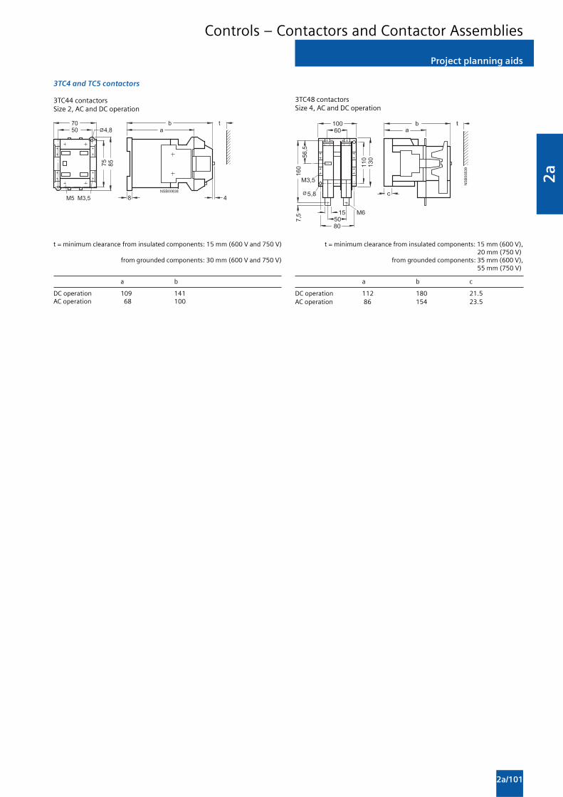
2a
2a/101
Project planning aids
Controls – Contactors and Contactor Assemblies
3TC4 and TC5 contactors
3TC44 contactorsSize 2, AC and DC operation
���� ���
��
��
����� �
� �
�
�������
t = minimum clearance from insulated components: 15 mm (600 V and 750 V)
from grounded components: 30 mm (600 V and 750 V)
a b
DC operation 109 141AC operation 68 100
3TC48 contactorsSize 4, AC and DC operation
�������
�����
����
���
���
���
���
������
��
���
��
�
�
�
t = minimum clearance from insulated components: 15 mm (600 V),20 mm (750 V)
from grounded components: 35 mm (600 V),55 mm (750 V)
a b c
DC operation 112 180 21.5AC operation 86 154 23.5

2a
2a/102
Project planning aids
Controls – Contactors and Contactor Assemblies
3TC4 and TC5 contactors
3TC52 contactorsSize 8, AC and DC operation
��������
�������
��
���
���
���
���� ��
�����
���
���
�����
��
� �
t = minimum clearance from insulated components: 20 mm (600 V and 750 V)from grounded components: 70 mm (600 V and 750 V)
a b
DC operation 147 232AC operation 115 200
3TC56 contactorsSize 12, AC and DC operation
���
���
������
��
��
���
���
����
����
�������
��
�
�
��������
�
���
��
��
��
t = minimum clearance from insulated components: 25 mm (600 V and 750 V)from grounded components: 80 mm (600 V),
100 mm (750 V)
a b
DC operation 200 310AC operation 141 251
1) DC operation only.

3ProtectionEquipment
3/2 Introduction
3RV Circuit Breakers/Motor Starter Protectors up to 100 A
3/4 General data
3/6 For motor protection
3/8 For motor protection with overload relayfunction
3/9 For starter combinations
3/10 For transformer protection
3/11 For fuse monitoring
3/12 For system protection according to UL489 / CSA C22.2 No. 5-02
Accessories
3/13 Mountable accessories
3/16 Busbar accessories
3/19 Rotary operating mechanisms
3/21 Mounting accessories
3/22 Enclosures and front plates
Overload Relays
3/24 General data
3RB2 Solid-State Overload Relays
3/29 3RB20, 3RB21 for standard applications
3/34 3RB22, 3RB23 for high-featureapplications
3/38 Accessories
3RU1 Thermal Overload Relays
3/40 3RU11 for standard applications
3/42 Accessories

3
3/2
Introduction
Overview
Protection Equipment
Type 3RV10 3RV11 3RV13 3RV14 3RV16 3RV16 3RV17
3RV1 circuit breakers/motor starter protectors up to 100 A Applications
System protection 1) 1) — — — —
Motor protection — — — — — —
Motor protection with — — — — — —overload relay function
Starter combinations — — — — — —
Transformer protection — — — — —
Fuse monitoring — — — — — —
Voltage transformer — — — — — —circuit breakers fordistance protection
Size S00, S0, S2, S3 S0, S2, S3 S0, S2, S3 S0, S2 S00 S00 S0, S3
Rated current In
Size S00 A up to 12 — — — up to 0.2 up to 3 —Size S0 A up to 25 up to 25 up to 25 up to 20 — — up to 22Size S2 A up to 50 up to 50 up to 50 up to 40 — — —Size S3 A up to 100 up to 100 up to 100 — — — up to 70
Rated operational V 690 AC2) 690 AC2) 690 AC2) 690 AC2) 690 AC2) 400 AC 690 ACvoltage Ue accordingto IEC
Rated frequency Hz 50/60 50/60 50/60 50/60 50/60 162/3 ... 60 50/60
Trip class CLASS 10 CLASS 10 — CLASS 10 — — —CLASS 20
Thermal A 0.11 ... 0.16 0.11 ... 0.16 none3) 0.11 ... 0.16 0.2 1.4 ... 3 0.16 ... 70overload release up to up to up to non-adjustable
A 80 ... 100 80 ... 100 28 ... 40
Electronic trip unitsA multiple of the rated current 13 times 13 times 13 times 20 times 6 times 4 ... 7 times 13 times
Short-circuit breaking kA 50/100 50/100 50/100 50/100 100 50 4)
capacity Icu at 400 V AC
AccessoriesFor sizes S00 S0 S2 S3 S0 S2 S3 S0 S2 S3 S0 S2 S00 S00 S0, S3
Auxiliary switches 5)
Signaling switches — — — —
Undervoltage trip units
Shunt trip units
Isolator modules — — — — — — —
Insulated three-phase — — — — —busbar systems
Busbar adapters —
Door-coupling rotary — — —operating mechanisms
Remote motorized — — — — — — — —operating mechanisms
Link modules —
Enclosures for surface — — — —mounting
Enclosures for flush — — — — — — — —mounting
Front plates —
Infeed systems — — — — — — — — — — —
1) For symmetrical loading of the three phases.
2) 500 V AC with molded-plastic enclosure.
3) For overload protection of the motors, appropriate overload relays mustbe used.
4) According to UL 489 at AC 480 Y/277 V.: for size S0 50 kA, for size S3 65 kA.
5) Only lateral auxiliary switches.
Has this function or can use this accessory
—Does not have this function or cannot use this accessory

3
3/3
Introduction
Protection Equipment
Type 3RU11 3RB20 3RB21 3RB22/3RB23
Overload relays up to 630 A Applications
System protection 1) 1) 1) 1)
Motor protection
Alternating current, 3-phase
Alternating current, 1-phase — —
DC current — — —
Size of contactor S00, S0, S2, S3 S00 ... S12 S00 ... S12 S00 ... S12
Rated operational current Ie
Size S00 A up to 12 up to 12 up to 12Size S0 A up to 25 up to 25 up to 25 } up to 25
Size S2 A up to 50 up to 50 up to 50Size S3 A up to 100 up to 100 up to 100 }
up to 100
Size S6 A — up to 200 up to 200 up to 200Size S10/S12, A — up to 630 up to 630 up to 630Size 14 (3TF6)
Rated operational voltage Ue V 690/1000 AC2) 690/1000 AC3) 690/1000 AC3) 690/1000 AC4)
Rated frequency Hz 50/60 50/60 50/60 50/60
Trip class CLASS 10 CLASS 10, CLASS 5, 10, 20, 30 CLASS 5, 10, 20, 30CLASS 20 adjustable adjustable
Thermal overload release AA 0.11 ... 0.16 — — —up to80 ... 100
Solid-state overload release A — 0.1 ... 0.4 0.1 ... 0.4 0.3 ... 3up to up to up to
A 160 ... 630 160 ... 630 63 ... 630
Rating for induction motor kW 0.04 0.04 ... 0.09 0.04 ... 0.09 0.09 ... 1.1at 400 V AC up to up to up to up to
kW 45 90 ... 450 90 ... 450 37 ... 450
AccessoriesFor sizes S00 S0 S2 S3 S00 S0 S2 S3 S6 S10/ S00 S0 S2 S3 S6 S10/ S00 S0 S2 S3 S6 S10/
S12 S12 S12Terminal brackets for 5) 5) 5) 5) 5) 5) 5) 5) 5) 5) 5) 5) 5) 5)
stand-alone installation
Mechanical RESET — — — — — —
Cable releases for RESET — — — — — —
Electrical remote RESET — — — — — — Integrated in the unit Integrated in the unit
Terminal covers — — — — — — — — — — —
Sealable covers for setting knobs Integrated in the unit
1) The units are responsible in the main circuit for overload protection ofthe assigned electrical loads (e.g. motors), feeder cable and otherswitching and protection devices in the respective load feeder.
2) Size S3 up to 1000 V AC.
3) Size S2 (only with straight-through transformer), S3, S6, S10, S12 up to1000 V AC.
4) With reference to the 3RB29 .6 current measuring modules.
5) Stand-alone installation without accessories is possible.
Has this function or can use this accessory
— Does not have this function or cannot use this accessory

3
3/4
Overview
General data
3RV Motor Starter Protectors up to 100 A
The following illustrations show our 3RV1 motor starterprotectors with the accessories which can be mounted for thevarious sizes, see also “Introduction” —> “Overview”.
NS
B0_
0142
6a
1
2
3
4
5
7
8
6.1
6.2
1
2
3
4
5
Motor starter protectors, sizes S0, S2 or S3, with mountable accessories
S00 motor starter protectors with mountable accessories
Transverse auxiliary switch (can not be used with 3RV17 and 3RV18 circuit breakers)Lateral auxiliary switch with 2 contactsLateral auxiliary switch with 4 contactsShunt releaseUndervoltage release
Mountable accessories for all sizes S00 ... S3
1
Mountable accessories
Undervoltage release withleading auxiliary contactsUndervoltage release withleading auxiliary contactsAlarm switchIsolator module
for sizes
2345
S00
S0 ... S3
S0 ... S3S0 and S2
78
6.1
6.2
For accessories, see page 3/13.

3
3/5
General data
3RV Motor Starter Protectors up to 100 A
Size S0 motor starter protectors
3RV1 motor starter protectors are compact, current limitingmotor starter protectors which are optimized for load feeders.The motor starter protectors are used for switching andprotecting three-phase induction motors of up to 45 kW at415 V AC and for other loads with rated currents of up to100 A.
Type of construction
The motor starter protectors are available in four sizes:
• Size S00 - width 45 mm,max. rated current 12 A,at 415 V AC suitable for induction motors up to 5.5 kW.
• Size S0 - width 45 mm,max. rated current 25 A,at 415 V AC suitable for induction motors up to 11 kW.
• Size S2 - width 55 mm,max. rated current 50 A,at 415 V AC suitable for induction motors up to 22 kW.
• Size S3 - width 70 mm,max. rated current 100 A,at 415 V AC suitable for induction motors up to 45 kW.
“Increased safety” type of protection EEx e according toATEX directive 94/9/EC
The 3RV10 motor starter protectors for motor protection aresuitable for the overload protection of explosion-proof motorswith “Increased Safety” type of protection EEx e;
Application
Operating conditions
3RV1 motor starter protectors are suitable for use in anyclimate. They are intended for use in enclosed rooms in whichno severe operating conditions (such as dust, caustic vapors,hazardous gases) prevail. When installed in dusty and dampareas, suitable enclosures must be provided.
3RV1 motor starter protectors can optionally be fed from thetop or from below.
The permissible ambient temperatures, the maximumswitching capacities, the tripping currents and other boundaryconditions can be found in the technical specifications andtripping characteristics.
3RV1 motor starter protectors are suitable for operation in ITsystems (IT networks). In this case, the different short-circuitbreaking capacity in the IT system must be taken into account.
Since operational currents, starting currents and current peaksare different even for motors with identical power ratings dueto the inrush current, the motor ratings in the selection tablesare only guide values. The specific rated and start-up data ofthe motor to be protected is always paramount to the choice ofthe most suitable motor starter protector. This also applies tomotor starter protectors for transformer protection.
Possible uses
The 3RV1 motor starter protectors can be used:
• For short-circuit protection
• For motor protection (also with overload relay function)
• For system protection
• For short-circuit protection for starter combinations
• For transformer protection
• As main control and EMERGENCY-STOP switches
• For fuse monitoring
• For use in IT systems (IT networks)
• For switching of DC currents
• As voltage transformer circuit breakers
• In areas subject to explosion hazard (ATEX)

3
3/6
For motor protection
3RV Motor Starter Protectors up to 100 A
Selection and ordering data
CLASS 10, without auxiliary switches
Rated Suitable for Setting range Instantaneous Short-circuit Screw terminals Weight percurrent induction for thermal electronic breaking PU approx.
motors1) overload trip unit capacity atwith P release 415 V AC
In Icu Order No. 2) kg
A kW A A kA
Size S00
0.16 0.04 0.11 ... 0.16 2.1 100 3RV10 11-0AA10 0.2300.2 0.06 0.14 ... 0.2 2.6 100 3RV10 11-0BA10 0.2310.25 0.06 0.18 ... 0.25 3.3 100 3RV10 11-0CA10 0.2330.32 0.09 0.22 ... 0.32 4.2 100 3RV10 11-0DA10 0.233
0.4 0.09 0.28 ... 0.4 5.2 100 3RV10 11-0EA10 0.2350.5 0.12 0.35 ... 0.5 6.5 100 3RV10 11-0FA10 0.2320.63 0.18 0.45 ... 0.63 8.2 100 3RV10 11-0GA10 0.2330.8 0.18 0.55 ... 0.8 10 100 3RV10 11-0HA10 0.235
1 0.25 0.7 ... 1 13 100 3RV10 11-0JA10 0.2331.25 0.37 0.9 ... 1.25 16 100 3RV10 11-0KA10 0.2791.6 0.55 1.1 ... 1.6 21 100 3RV10 11-1AA10 0.2812 0.75 1.4 ... 2 26 100 3RV10 11-1BA10 0.280
2.5 0.75 1.8 ... 2.5 33 100 3RV10 11-1CA10 0.2813.2 1.1 2.2 ... 3.2 42 100 3RV10 11-1DA10 0.2834 1.5 2.8 ... 4 52 100 3RV10 11-1EA10 0.2815 1.5 3.5 ... 5 65 100 3RV10 11-1FA10 0.285
6.3 2.2 4.5 ... 6.3 82 100 3RV10 11-1GA10 0.2888 3 5.5 ... 8 104 50 3RV10 11-1HA10 0.28910 4 7 ... 10 130 50 3RV10 11-1JA10 0.28412 5.5 9 ... 12 156 50 3RV10 11-1KA10 0.280
Size S0
0.16 0.04 0.11 ... 0.16 2.1 100 3RV10 21-0AA10 0.2860.2 0.06 0.14 ... 0.2 2.6 100 3RV10 21-0BA10 0.2880.25 0.06 0.18 ... 0.25 3.3 100 3RV10 21-0CA10 0.2870.32 0.09 0.22 ... 0.32 4.2 100 3RV10 21-0DA10 0.286
0.4 0.09 0.28 ... 0.4 5.2 100 3RV10 21-0EA10 0.2880.5 0.12 0.35 ... 0.5 6.5 100 3RV10 21-0FA10 0.2870.63 0.18 0.45 ... 0.63 8.2 100 3RV10 21-0GA10 0.2890.8 0.18 0.55 ... 0.8 10 100 3RV10 21-0HA10 0.287
1 0.25 0.7 ... 1 13 100 3RV10 21-0JA10 0.3501.25 0.37 0.9 ... 1.25 16 100 3RV10 21-0KA10 0.3531.6 0.55 1.1 ... 1.6 21 100 3RV10 21-1AA10 0.3572 0.75 1.4 ... 2 26 100 3RV10 21-1BA10 0.356
2.5 0.75 1.8 ... 2.5 33 100 3RV10 21-1CA10 0.3573.2 1.1 2.2 ... 3.2 42 100 3RV10 21-1DA10 0.3564 1.5 2.8 ... 4 52 100 3RV10 21-1EA10 0.3545 1.5 3.5 ... 5 65 100 3RV10 21-1FA10 0.358
6.3 2.2 4.5 ... 6.3 82 100 3RV10 21-1GA10 0.3578 3 5.5 ... 8 104 100 3RV10 21-1HA10 0.35610 4 7 ... 10 130 100 3RV10 21-1JA10 0.36112.5 5.5 9 ... 12.5 163 100 3RV10 21-1KA10 0.358
16 7.5 11 ... 16 208 50 3RV10 21-4AA10 0.36620 7.5 14 ... 20 260 50 3RV10 21-4BA10 0.36322 11 17 ... 22 286 50 3RV10 21-4CA10 0.36125 11 20 ... 25 325 50 3RV10 21-4DA10 0.364
1) Guide value for 4-pole standard motors at 50 Hz 415 V AC. The actualstarting and rated data of the motor to be protected must be consideredwhen selecting the units.
2) The 12th digit (last) of the MLFB to be changed to ‘5’ for MPCB with 1NO+ 1NC block.

3
3/7
For motor protection
3RV Motor Starter Protectors up to 100 A
CLASS 10, without auxiliary switches
Rated Suitable for Setting range Instantaneous Short-circuit Screw terminals Weight percurrent three-phase for thermal electronic breaking PU approx.
induction overload trip unit capacity atmotors1) release 415 V ACwith P
In Icu Order No. 2) kg
A kW A A kA
Size S2
16 7.5 11 ... 16 208 50 3RV10 31-4AA10 1.04620 7.5 14 ... 20 260 50 3RV10 31-4BA10 1.04325 11 18 ... 25 325 50 3RV10 31-4DA10 1.03132 15 22 ... 32 416 50 3RV10 31-4EA10 1.028
40 18.5 28 ... 40 520 50 3RV10 31-4FA10 1.04745 22 36 ... 45 585 50 3RV10 31-4GA10 1.03950 22 40 ... 50 650 50 3RV10 31-4HA10 1.027
Size S3
40 18.5 28 ... 40 520 50 3RV10 41-4FA10 2.21950 22 36 ... 50 650 50 3RV10 41-4HA10 2.24063 30 45 ... 63 819 50 3RV10 41-4JA10 2.247
75 37 57 ... 75 975 50 3RV10 41-4KA10 2.25390 45 70 ... 90 1170 50 3RV10 41-4LA10 2.280100 45 80 ... 100 1235 50 3RV10 41-4MA10 2.295
Size S3, with increased switching capacity
16 7.5 11 ... 16 208 100 3RV10 42-4AA10 2.17420 7.5 14 ... 20 260 100 3RV10 42-4BA10 2.18525 11 18 ... 25 325 100 3RV10 42-4DA10 2.21132 15 22 ... 32 416 100 3RV10 42-4EA10 2.222
40 18.5 28 ... 40 520 100 3RV10 42-4FA10 2.20350 22 36 ... 50 650 100 3RV10 42-4HA10 2.23063 30 45 ... 63 819 100 3RV10 42-4JA10 2.255
75 37 57 ... 75 975 100 3RV10 42-4KA10 2.26690 45 70 ... 90 1170 100 3RV10 42-4LA10 2.268100 45 80 ... 100 1235 100 3RV10 42-4MA10 2.275
CLASS 20, without auxiliary switches
Size S2
16 7.5 11 ... 16 208 50 3RV10 31-4AB10 1.06720 7.5 14 ... 20 260 50 3RV10 31-4BB10 1.07125 11 18 ... 25 325 50 3RV10 31-4DB10 1.05432 15 22 ... 32 416 50 3RV10 31-4EB10 1.067
40 18.5 28 ... 40 520 50 3RV10 31-4FB10 1.07645 22 36 ... 45 585 50 3RV10 31-4GB10 1.07350 22 40 ... 50 650 50 3RV10 31-4HB10 1.071
Size S3, with increased switching capacity
40 18.5 28 ... 40 520 100 3RV10 42-4FB10 2.22250 22 36 ... 50 650 100 3RV10 42-4HB10 2.26563 30 45 ... 63 819 100 3RV10 42-4JB10 2.278
75 37 57 ... 75 975 100 3RV10 42-4KB10 2.26890 45 70 ... 90 1170 100 3RV10 42-4LB10 2.313100 45 80 ... 100 1235 100 3RV10 42-4MB10 2.322
1) Guide value for 4-pole standard motors at 50 Hz 415 V AC. The actualstarting and rated data of the motor to be protected must be consideredwhen selecting the units.

3
3/8
For motor protection with overload relay function
3RV Motor Starter Protectors up to 100 A
Selection and ordering data
CLASS 10, with overload relay function (automatic RESET), without auxiliary switches
Rated Suitable for Setting range Instantaneous Short-circuit Screw terminals Weight percurrent three-phase for thermal electronic breaking PU approx.
induction overload trip unit capacity atmotors1) release 415 V ACwith P
In Icu Order No. kg
A kW A A kA
Size S02)
0.16 0.04 0.11 ... 0.16 2.1 100 3RV11 21-0AA10 0.3540.2 0.06 0.14 ... 0.2 2.6 100 3RV11 21-0BA10 0.3580.25 0.06 0.18 ... 0.25 3.3 100 3RV11 21-0CA10 0.3520.32 0.09 0.22 ... 0.32 4.2 100 3RV11 21-0DA10 0.352
0.4 0.09 0.28 ... 0.4 5.2 100 3RV11 21-0EA10 0.3550.5 0.12 0.35 ... 0.5 6.5 100 3RV11 21-0FA10 0.3560.63 0.18 0.45 ... 0.63 8.2 100 3RV11 21-0GA10 0.3580.8 0.18 0.55 ... 0.8 10 100 3RV11 21-0HA10 0.421
1 0.25 0.7 ... 1 13 100 3RV11 21-0JA10 0.4161.25 0.37 0.9 ... 1.25 16 100 3RV11 21-0KA10 0.4261.6 0.55 1.1 ... 1.6 21 100 3RV11 21-1AA10 0.4222 0.75 1.4 ... 2 26 100 3RV11 21-1BA10 0.427
2.5 0.75 1.8 ... 2.5 33 100 3RV11 21-1CA10 0.4223.2 1.1 2.2 ... 3.2 42 100 3RV11 21-1DA10 0.4284 1.5 2.8 ... 4 52 100 3RV11 21-1EA10 0.4205 1.5 3.5 ... 5 65 100 3RV11 21-1FA10 0.429
6.3 2.2 4.5 ... 6.3 82 100 3RV11 21-1GA10 0.4268 3 5.5 ... 8 104 100 3RV11 21-1HA10 0.42510 4 7 ... 10 130 100 3RV11 21-1JA10 0.42812.5 5.5 9 ... 12.5 163 100 3RV11 21-1KA10 0.426
16 7.5 11 ... 16 208 50 3RV11 21-4AA10 0.43620 7.5 14 ... 20 260 50 3RV11 21-4BA10 0.43022 11 17 ... 22 286 50 3RV11 21-4CA10 0.42725 11 20 ... 25 325 50 3RV11 21-4DA10 0.432
Size S22)
16 7.5 11 ... 16 208 50 3RV11 31-4AA10 1.12320 7.5 14 ... 20 260 50 3RV11 31-4BA10 1.10925 11 18 ... 25 325 50 3RV11 31-4DA10 1.11432 15 22 ... 32 416 50 3RV11 31-4EA10 1.111
40 18.5 28 ... 40 520 50 3RV11 31-4FA10 1.12345 22 36 ... 45 585 50 3RV11 31-4GA10 1.10150 22 40 ... 50 650 50 3RV11 31-4HA10 1.106
Size S3, with increased switching capacity2)
16 7.5 11 ... 16 208 100 3RV11 42-4AA10 2.24720 7.5 14 ... 20 260 100 3RV11 42-4BA10 2.25525 11 18 ... 25 325 100 3RV11 42-4DA10 2.28432 15 22 ... 32 416 100 3RV11 42-4EA10 2.295
40 18.5 28 ... 40 520 100 3RV11 42-4FA10 2.28850 22 36 ... 50 650 100 3RV11 42-4HA10 2.32063 30 45 ... 63 819 100 3RV11 42-4JA10 2.333
75 37 57 ... 75 975 100 3RV11 42-4KA10 2.36890 45 70 ... 90 1170 100 3RV11 42-4LA10 2.353100 45 80 ... 100 1235 100 3RV11 42-4MA10 2.346
1) Guide value for 4-pole standard motors at 50 Hz 415 V AC. The actualstarting and rated data of the motor to be protected must be consideredwhen selecting the units.
2) Accessories for mounting on the right (for sizes S0 to S3) and 3RV19 15three-phase busbars (for size S0) cannot be used.

3
3/9
For starter combinations
3RV Motor Starter Protectors up to 100 A
Selection and ordering data
Without auxiliary switches
Rated Suitable for Thermal overload Instantaneous Short-circuit Screw terminals Weight percurrent three-phase release2) electronic breaking PU approx.
induction trip unit capacity atmotors1) 415 V ACwith P
In Icu Order No. kg
A kW A A kA
Size S0
0.16 0.04 None 2.1 100 3RV13 21-0AC10 0.2820.2 0.06 None 2.6 100 3RV13 21-0BC10 0.2840.25 0.06 None 3.3 100 3RV13 21-0CC10 0.2850.32 0.09 None 4.2 100 3RV13 21-0DC10 0.282
0.4 0.09 None 5.2 100 3RV13 21-0EC10 0.2860.5 0.12 None 6.5 100 3RV13 21-0FC10 0.2830.63 0.18 None 8.2 100 3RV13 21-0GC10 0.3480.8 0.18 None 10 100 3RV13 21-0HC10 0.283
1 0.25 None 13 100 3RV13 21-0JC10 0.3451.25 0.37 None 16 100 3RV13 21-0KC10 0.3511.6 0.55 None 21 100 3RV13 21-1AC10 0.3522 0.75 None 26 100 3RV13 21-1BC10 0.352
2.5 0.75 None 33 100 3RV13 21-1CC10 0.3523.2 1.1 None 42 100 3RV13 21-1DC10 0.3534 1.5 None 52 100 3RV13 21-1EC10 0.3495 1.5 None 65 100 3RV13 21-1FC10 0.354
6.3 2.2 None 82 100 3RV13 21-1GC10 0.3558 3 None 104 100 3RV13 21-1HC10 0.35410 4 None 130 100 3RV13 21-1JC10 0.35712.5 5.5 None 163 100 3RV13 21-1KC10 0.354
16 7.5 None 208 50 3RV13 21-4AC10 0.36220 7.5 None 260 50 3RV13 21-4BC10 0.35722 11 None 286 50 3RV13 21-4CC10 0.35825 11 None 325 50 3RV13 21-4DC10 0.359
Size S2
16 7.5 None 208 50 3RV13 31-4AC10 1.03820 7.5 None 260 50 3RV13 31-4BC10 1.03725 11 None 325 50 3RV13 31-4DC10 1.01432 15 None 416 50 3RV13 31-4EC10 1.018
40 18.5 None 520 50 3RV13 31-4FC10 1.03345 22 None 585 50 3RV13 31-4GC10 1.04050 22 None 650 50 3RV13 31-4HC10 1.019
Size S3
40 18.5 None 520 50 3RV13 41-4FC10 2.19750 22 None 650 50 3RV13 41-4HC10 2.22763 30 None 819 50 3RV13 41-4JC10 2.244
75 37 None 975 50 3RV13 41-4KC10 2.24790 45 None 1170 50 3RV13 41-4LC10 2.269100 45 None 1235 50 3RV13 41-4MC10 2.292
Size S3, with increased switching capacity
16 7.5 None 208 100 3RV13 42-4AC10 2.17520 7.5 None 260 100 3RV13 42-4BC10 2.18825 11 None 325 100 3RV13 42-4DC10 2.21932 15 None 416 100 3RV13 42-4EC10 2.208
40 18.5 None 520 100 3RV13 42-4FC10 2.21850 22 None 650 100 3RV13 42-4HC10 2.21863 30 None 819 100 3RV13 42-4JC10 2.248
75 37 None 975 100 3RV13 42-4KC10 2.27890 45 None 1170 100 3RV13 42-4LC10 2.266100 45 None 1235 100 3RV13 42-4MC10 2.293
1) Guide value for 4-pole standard motors at 50 Hz 415 V AC. The actualstarting and rated data of the motor to be protected must be consideredwhen selecting the units.
2) For overload protection of the motors, appropriate overload relays mustbe used.

3
3/10
Selection and ordering data
CLASS 10, without auxiliary switches
Motor starter protectors for the protection of transformers with high inrush current
For transformer protection
3RV Motor Starter Protectors up to 100 A
Rated current Setting range Instantaneous Short-circuit Screw terminals Weight perfor thermal electronic breaking PU approx.overload trip unit capacity atrelease 415 V AC
In Icu Order No. kg
A A A kA
Size S0
0.16 0.11 ... 0.16 3.3 100 3RV14 21-0AA10 0.2860.2 0.14 ... 0.2 4.2 100 3RV14 21-0BA10 0.2870.25 0.18 ... 0.25 5.2 100 3RV14 21-0CA10 0.2860.32 0.22 ... 0.32 6.5 100 3RV14 21-0DA10 0.288
0.4 0.28 ... 0.4 8.2 100 3RV14 21-0EA10 0.2870.5 0.35 ... 0.5 10 100 3RV14 21-0FA10 0.2860.63 0.45 ... 0.63 13 100 3RV14 21-0GA10 0.2900.8 0.55 ... 0.8 16 100 3RV14 21-0HA10 0.290
1 0.7 ... 1 21 100 3RV14 21-0JA10 0.3531.25 0.9 ... 1.25 26 100 3RV14 21-0KA10 0.3541.6 1.1 ... 1.6 33 100 3RV14 21-1AA10 0.3532 1.4 ... 2 42 100 3RV14 21-1BA10 0.358
2.5 1.8 ... 2.5 52 100 3RV14 21-1CA10 0.3543.2 2.2 ... 3.2 65 100 3RV14 21-1DA10 0.3584 2.8 ... 4 82 100 3RV14 21-1EA10 0.3545 3.5 ... 5 104 100 3RV14 21-1FA10 0.357
6.3 4.5 ... 6.3 130 100 3RV14 21-1GA10 0.3568 5.5 ... 8 163 100 3RV14 21-1HA10 0.35810 7 ... 10 208 100 3RV14 21-1JA10 0.36212.5 9 ... 12.5 260 100 3RV14 21-1KA10 0.360
16 11 ... 16 286 50 3RV14 21-4AA10 0.36520 14 ... 20 325 50 3RV14 21-4BA10 0.365
Size S2
16 11 ... 16 325 50 3RV14 31-4AA10 1.02920 14 ... 20 416 50 3RV14 31-4BA10 1.03425 18 ... 25 520 50 3RV14 31-4DA10 1.03832 22 ... 32 660 50 3RV14 31-4EA10 1.02940 28 ... 40 836 50 3RV14 31-4FA10 1.039
Auxiliary switches can be ordered separately(see “Mountable accessories”).

3
3/11
For fuse monitoring
3RV Motor Starter Protectors up to 100 A
Selection and ordering data
Without auxiliary switches
Rated current Thermal Instantaneous Short-circuit Screw terminals Weight peroverload release electronic breaking PU approx.
trip unit capacity at415 V AC
In Icu Order No. kg
A A A kA
Size S00
0.2 0.2 1.2 100 3RV16 11-0BD10 0.289
Note:
The auxiliary switch required for signaling must be orderedseparately.
Accessories
Type Version Screw terminals Weight perPU approx.
Order No. kg
Mountable auxiliary switches (essential accessories)
Transverse auxiliary switches 1 NO + 1 NC 3RV19 01-1E 0.018With screw terminals,mountable on front
3RV19 01-1E
Lateral auxiliary switches 1 NO + 1 NC 3RV19 01-1A 0.045With screw terminals,mountable on the left
3RV19 01-1A

3
3/12
Selection and ordering data
Without auxiliary switches
Circuit breakers for system protection and non-motor loads according to UL/CSA
For system protectionaccording to UL 489 / CSA C22.2 No. 5-02
3RV Circuit Breakers up to 100 A
Rated current Thermal Instantaneous Short-circuit Screw terminals Weight peroverload electronic breaking PU approx.releases trip unit capacity at(non-adjustable) AC 480 Y/277 V1)
In Ibc Order No. kg
A A A kA
Size S0
0.16 0.16 2.1 50 3RV17 21-0AD10 0.4600.2 0.2 2.6 50 3RV17 21-0BD10 0.4600.25 0.25 3.3 50 3RV17 21-0CD10 0.4600.32 0.32 4.2 50 3RV17 21-0DD10 0.460
0.4 0.4 5.2 50 3RV17 21-0ED10 0.4600.5 0.5 6.5 50 3RV17 21-0FD10 0.4600.63 0.63 8.2 50 3RV17 21-0GD10 0.4600.8 0.8 10 50 3RV17 21-0HD10 0.530
1 1 13 50 3RV17 21-0JD10 0.5301.25 1.25 16 50 3RV17 21-0KD10 0.5301.6 1.6 21 50 3RV17 21-1AD10 0.5302 2 26 50 3RV17 21-1BD10 0.530
2.5 2.5 33 50 3RV17 21-1CD10 0.5303.2 3.2 42 50 3RV17 21-1DD10 0.5304 4 52 50 3RV17 21-1ED10 0.5305 5 65 50 3RV17 21-1FD10 0.530
6.3 6.3 82 50 3RV17 21-1GD10 0.5308 8 104 50 3RV17 21-1HD10 0.53010 10 130 50 3RV17 21-1JD10 0.53012.5 12.5 163 50 3RV17 21-1KD10 0.530
15 15 208 50 3RV17 21-4AD10 0.53020 20 260 50 3RV17 21-4BD10 0.53022 22 286 50 3RV17 21-4CD10 0.530
Size S3
10 10 150 65 3RV17 42-5AD10 0.46015 15 225 65 3RV17 42-5BD10 0.460
20 20 260 65 3RV17 42-5CD10 0.46025 25 325 65 3RV17 42-5DD10 0.46030 30 390 65 3RV17 42-5ED10 0.46035 35 455 65 3RV17 42-5FD10 0.460
40 40 520 65 3RV17 42-5GD10 0.46045 45 585 65 3RV17 42-5HD10 0.46050 50 650 65 3RV17 42-5JD10 0.460
60 60 780 65 3RV17 42-5LD10 0.46070 70 910 65 3RV17 42-5QD10 0.460
1) For values for AC 600 Y/347 V, see protection equipment, Chapter 3a/10.
Transverse auxiliary switches must not be mounted, lateralauxiliary switches can be ordered separately

3
3/13
Mountable accessories
3RV Motor Starter Protectors up to 100 A
Overview
Mounting location and function
The 3RV1 motor starter protectors have three main contactelements. In order to achieve maximum flexibility, auxiliaryswitches, signaling switches, auxiliary trip units and isolatormodules can be supplied separately.
These components can be fitted as required on the motorstarter protectors without using tools.
Front side Transverse auxiliary switches An auxiliary switch block can be inserted transversely on the front. The overall
Notes: 1 NO + 1 NC width of the motor starter protectors remains unchanged.
• A maximum of 4 auxiliary orcontacts with auxiliary switches 2 NOcan be attached to each ormotor starter protector. 1 CO contact
• Transverse auxiliary switchesmust not be used for the 3RV17motor starter protectors.
Left-hand side Lateral auxiliary switches One of the three auxiliary switches can be mounted laterally for each motor starter
Notes: (2 contacts) protector. The contacts of the auxiliary switch close and open together with the main
• A maximum of 4 auxiliary 1 NO + 1 NC contacts of the motor starter protector.
contacts with auxiliary switches or The overall width of the lateral auxiliary switch with 2 contacts is 9 mm.can be attached to each motor 2 NOstarter protector. or
• Auxiliary switches (2 contacts) 2 NC
and signaling switches can be Lateral auxiliary switches One auxiliary switch can be mounted laterally for each motor starter protector. Themounted separately or together. (4 contacts) contacts of the auxiliary switch close and open together with the main contacts of
2 NO + 2 NC the motor starter protector.
The overall width of the lateral auxiliary switch with 4 contacts is 18 mm.
Signaling switches for One signaling switch can be mounted at the side of each motor starter protectorsizes S0, S2 and S3 with a rotary operating mechanism.
Tripping 1 NO + 1 NC The signaling switch has two contact systems.Short-circuit 1 NO + 1 NC One contact system always signals tripping irrespective of whether this was caused
by a short-circuit, an overload or an auxiliary trip unit. The other contact system onlyswitches in the event of a short-circuit. There is no signaling as a result ofswitching off with the handle.
In order to be able to switch on the motor starter protector again after a short-circuit,the signaling switch must be reset manually after the error cause has beeneliminated.The overall width of the signaling switch is 18 mm.
Right-hand side Shunt trip units For remote-controlled tripping of the motor starter protector. The release coil
Notes: should only be energized for short periods (see schematics).
• One auxiliary trip unit can be or
mounted per motor starter Undervoltage releases Trips the motor starter protector when the voltage is interrupted and prevents theprotector. motor from being restarted accidentally when the voltage is restored. Used for
• Accessories cannot be mounted remote-controlled tripping of the motor starter protector.
at the right-hand side of the Particularly suitable for EMERGENCY-STOP disconnection by way of the3RV11 motor starter protectors corresponding EMERGENCY-STOP pushbutton according to DIN VDE 0113.with overload relay function.
or
Undervoltage trip unit with Function and use as for the undervoltage trip unit without leading auxiliary contacts,leading auxiliary contacts but with the following additional function: the auxiliary contacts will open in switch(2 NO) position OFF to deenergize the coil of the undervoltage trip unit, thus interrupting
energy consumption. In the “tripped” position of the breaker, these auxiliary contactsare not guaranteed to open. The leading contacts permit the motor starter protectorto reclose.
The overall width of the auxiliary trip unit is 18 mm.
Top Isolator modules for Isolator modules can be mounted to the upper terminal end of motor starter
Note: sizes S0 and S2 protectors of sizes S0 and S2.
The isolator module covers the The supply cable is connected to the motor starter protector through the isolator
terminal screws of the module.
transverse auxiliary switch. The plug can only be unplugged when the motor starter protector is openIf the isolator module is used, and isolates all 3 poles of the motor starter protector from the network. Thewe therefore recommend that shock-protected isolation point is clearly visible and secured with a padlock toeither the lateral auxiliary prevent reinsertion of the plug.switches be fitted or that theisolator module not bemounted until the auxiliaryswitch has been wired.

3
3/14
Mountable accessories
3RV Motor Starter Protectors up to 100 A
Selection and ordering data
Type Version For motor starter Screw terminals Weight perprotectors PU approx.Size
Order No. kg
Auxiliary switches1)
Transverse auxiliary switches 1 CO S00, S0, S2, S3 3RV19 01-1D 0.015With screw terminals, 1 NO + 1 NC 3RV19 01-1E 0.018mountable on front 2 NO2) 3RV19 01-1F 0.018
3RV19 01-1E
Covers for transverse — S00, S0, S2, S3 3RV19 01-0H 0.006auxiliary switches
3RV19 01-0H
Lateral auxiliary switches 1 NO + 1 NC S00, S0, S2, S3 3RV19 01-1A 0.045With screw terminals, 2 NO 3RV19 01-1B 0.045mountable on the left 2 NC 3RV19 01-1C 0.045
2 NO + 2 NC 3RV19 01-1J 0.083
3RV19 01-1A
3RV19 01-1J
Signaling switches
Signaling switches Separate tripped and S0, S2, S3 3RV19 21-1M 0.094One signaling switch can be short-circuit alarms,mounted on the left per 1 NO + 1 NC eachmotor starter protector.
3RV19 21-1M
Isolator modules
Isolator modules Visible isolating distance S0 3RV19 28-1A 0.157for isolating individualmotor starter protectors S2 3RV19 38-1A 0.324from the network,lockable in disconnectedposition.
3RV19 38-1Awith padlock
1) Each motor starter protector can be fitted with one transverse and onelateral auxiliary switch. The lateral auxiliary switch with 2 NO + 2 NC isused without a transverse auxiliary switch. Transverse auxiliary switchesmust not be used for the 3RV17 and 3RV18 motor starter protectors.
2) Compatible with the following motor starter protectors:3RV1. 1 (size S00) as of product version E013RV1. 2 (size S0) as of product version E043RV1. 3 (size S2) as of product version E043RV1. 4 (size S3) as of product version E04

3
3/15
Mountable accessories
3RV Motor Starter Protectors up to 100 A
Rated control supply voltage Us For motor starter Screw terminals Weight perAC AC AC AC/DC DC protectors Size PU approx.50 Hz 60 Hz 50/60 Hz 50/60 Hz, DC
100% ON 5 s ONperiod1) period2)
Order No. kg
V V V V V
Auxiliary trip units3)
Undervoltage trip units
230 240 — — — S00, S0, S2, S3 3RV19 02-1AP0 0.131400 440 — — — S00, S0, S2, S3 3RV19 02-1AV0 0.127
3RV19 02-1DP0
Undervoltage trip units with leading auxiliary contacts 2 NO
230 240 — — — S00 3RV19 12-1CP0 0.140415 480 — — — S00 3RV19 12-1CV1 0.139
230 240 — — — S0, S2, S3 3RV19 22-1CP0 0.139415 480 — — — S0, S2, S3 3RV19 22-1CV1 0.138
3RV19 12-1CP0
Shunt trip units
— — 20 ... 24 20 ... 70 — S00, S0, S2, S3 3RV19 02-1DB0 0.133— — 90 ... 110 70 ... 190 — S00, S0, S2, S3 3RV19 02-1DF0 0.135— — 210 ... 240 190 ... 330 — S00, S0, S2, S3 3RV19 02-1DP0 0.130
1) The voltage range is valid for 100% (infinite) ON period. The responsevoltage is at 0.9 the lower limit of the voltage range.
2) The voltage range is valid for 5 s ON period at AC 50 Hz/60 Hz and DC.The response voltage is at 0.85 the lower limit of the voltage range.
3) One auxiliary trip unit can be mounted on the right per motor starterprotector.

3
3/16
Busbar accessories
3RV Motor Starter Protectors up to 100 A
Insulated three-phase busbar systems
Three-phase busbar systems provide an easy, time-saving andclearly arranged means of feeding 3RV1 circuit breakers/ motorstarter protectors with screw terminals. Different versions areavailable for sizes S00, S0 and S2 and can be used for thevarious different types of circuit breakers/ motor starterprotectors. The only exceptions are the 3RV19 15 three-phasebusbar systems, which are not suitable for the 3RV11 motorstarter protectors with overload relay function.
The busbars are suitable for between 2 and 5 circuit breakers/motor starter protectors. However, any kind of extension ispossible by clamping the tags of an additional busbar (rotatedby 180°) underneath the terminals of the respective last circuitbreaker/ motor starter protector.
A combination of circuit breakers/ motor starter protectors ofdifferent sizes is possible only with sizes S00 and S0.Connectors are available for this purpose. The motor starterprotectors are supplied by appropriate feeder terminals.
Overview
The three-phase busbar systems are finger-safe. They aredesigned for any short-circuit stress which can occur at theoutput side of connected motor starter protectors.
The three-phase busbar systems can also be used to construct“Type E Starters” of size S0 or S2 according to UL/CSA.
Special feeder terminals must be used for this purpose,however (see “Selection and ordering data”).
Busbar adapters for 40 mm and 60 mm systems
The motor starter protectors are mounted directly with the aidof busbar adapters on busbar systems with 40 mm and 60 mmcenter-to-center clearance in order to save space and to reduceinfeed times and costs.
Busbar adapters for busbar systems with 40 mm center-to-center clearance are suitable for copper busbars with a widthof 12 mm to 15 mm, while those with 60 mm center-to-centerclearance are suitable for copper busbars with a width of12 mm to 30 mm. The busbars can be 4 to 5 mm or 10 mmthick.
The circuit breakers/ motor starter protectors are snapped ontothe adapter and connected on the line side. This prepared unitis then plugged directly onto the busbar system, and is thusconnected both mechanically and electrically at the same time.
���������
��� �������
��� ������
��� ������
��� �������
������������������
3-phase busbar system, size S00
3-phase busbar system, size S2
3-phase busbar system, with example for combining sizes S00 and S0
����������
���������
����������
��
��
����
�����������
���������
������ ���
����������� ����������!
��
��
����
����������
SIRIUS motor starter protectors and load feeders with busbar adapterssnapped onto busbars
SIRIUS 3RV19 infeed system with three 3RV10 11 motor starterprotectors, two 3RV10 21 motor starter protectors, three 3RT10 16contactors and two 3RT10 24 contactors

3
3/17
Busbar accessories
3RV Motor Starter Protectors up to 100 A
Selection and ordering data
Modular Number of motor starter protectors Rated For motor Order No. Weight perspacing that can be connected current starter PU approx.
In at 690 V protectorsWithout Incl.lateral With Sizelateral auxiliary auxiliaryaccessories switch trip unit
mm A kg
3-phase busbar systems
For feeding several motor starter protectors with screw terminals, mountedside by side on standard mounting rails, insulated, with touch protection
45 2 — — 63 S00, S01) 3RV19 15-1AB 0.0443RV19 15-1AB 3 S00, S01) 3RV19 15-1BB 0.071
4 S00, S01) 3RV19 15-1CB 0.0995 S00, S01) 3RV19 15-1DB 0.124
55 — 2 — 63 S00, S01) 3RV19 15-2AB 0.0483RV19 15-1BB 3 S00, S01) 3RV19 15-2BB 0.079
4 S00, S01) 3RV19 15-2CB 0.1115 S00, S01) 3RV19 15-2DB 0.140
63 — — 2 63 S00, S01) 3RV19 15-3AB 0.0523RV19 15-1CB 4 S00, S01) 3RV19 15-3CB 0.120
55 2 — — 108 S2 3RV19 35-1A 0.1503 S2 3RV19 35-1B 0.2144 S2 3RV19 35-1C 0.295
3RV19 15-1DB 75 — 2 2 108 S22) 3RV19 35-3A 0.1613 3 S22) 3RV19 35-3B 0.2624 4 S22) 3RV19 35-3C 0.369
1) Not suitable for 3RV11 motor starter protectors with overload relayfunction. Common clamping of S00 and S0 motor starter protectors is notpossible, due to the different modular spacings and terminal heights. The3RV19 15-DB connector is available for connecting busbars from size S0to size S00.
2) Auxiliary trip units and lateral auxiliary switches cannot be used incombination.
Conductor cross-section For motor Order No. Weight perstarter protectors PU approx.
Solid or Finely stranded AWG cable, Sizestranded with end sleeve solid or stranded
mm² mm² AWG kg
3-phase feeder terminals
Connection from top
2.5 ... 25 4 ... 16 12-4 S00 3RV19 15-5A 0.040
S0 3RV19 25-5AB 0.041
Connection from below1)
3RV19 25-5AB 2.5 ... 25 4 ... 16 12-4 S00, S0 3RV19 15-5B 0.110
Connection from top
2.5 ... 50 1.5 ... 35 14-0 S2 3RV19 35-5A 0.110
3RV19 15-5B
1) This terminal is connected in place of a switch, please take the spacerequirement into account.

3
3/18
Busbar accessories
3RV Motor Starter Protectors up to 100 A
Busbar adapters
8US10 61-5DJ07 8US12 51-5MD07
For motor starter Rated Connecting Adapter Adapter Rated Order No. Weight perprotectors current cable length width voltage PU approx.Size
A AWG mm mm V kg
Busbar adapters for 40 mm systems
For flat copper profiles according to DIN 46433Width: 12 mm and 15 mm Thickness: 5 mm and 10 mm
S00, S0 25 12 121 45 690 8US10 51-5DJ07 0.106
S00, S0 + lateral 25 12 121 55 690 8US10 61-5DJ07 0.119auxiliary switch
S2 56 8 139 55 690 8US10 61-5FK08 0.231
S3 100 4 182 70 4001) 8US11 11-4SM00 0.541
S3 100 4 182 72 415 ... 6902) 8US10 11-4TM00 0.478
Busbar adapters for 60 mm systems
For flat copper profiles according to DIN 46433Width: 12 mm and 30 mmThickness: 5 mm and 10 mmalso for T and double-T special profiles
S00, S0 25 12 182 45 690 8US12 51-5DM07 0.183
S2 56 8 55 690 8US12 61-5FM08 0.263
S3 100 4 70 4001) 8US11 11-4SM00 0.541
S3 100 4 72 415 ... 6902) 8US12 11-4TM00 0.498
1) Up to 460 V AC with max. short-circuit breaking capacity 25 kA.
2) Short-circuit breaking capacity 415/500/525 V AC:- up to In = 25 A: max. 30 kA- up to In = 90 A: max. 16 kA- up to In = 100 A: max. 6 kA;Short-circuit breaking capacity 690 V AC:- max. 12 kA.

3
3/19
Rotary operating mechanisms
3RV Motor Starter Protectors up to 100 A
Overview
Door-coupling rotary operating mechanisms
Motor starter protectors with a rotary operating mechanismcan be mounted in a control cabinet and operated externally bymeans of a door-coupling rotary operating mechanism. Whenthe cabinet door with motor starter protector is closed, theoperating mechanism is coupled. When the motor starterprotector closes, the coupling is locked which prevents thedoor from being opened unintentionally. This interlock can bedefeated by the maintenance
personnel. In the open position, the rotary operatingmechanism can be secured against reclosing with up to 3padlocks. Inadvertent opening of the door is not possible in thiscase either.
3RV19 26-1B door-coupling rotary operating mechanism for arduousconditions
If the motor starter protector is tripped as a result of overloador short-circuit, it will be in tripped position. For reclosing, theremote motorized operating mechanism must first be setmanually or electrically to the 0 position (electrically by meansof the Open command). Then it can be reclosed.
The remote motorized operating mechanism is available formotor starter protectors of size S2 (In max = 50 A) and S3(In max =100 A) that are designed for control voltages of230 V AC and 24 V DC. The motor starter protector is fitted intothe remote motorized operating mechanism as shown in thedrawing.
In the “MANUAL” position, the motor starter protector in theremote motorized operating mechanism can continue to beswitched manually on site. In the “AUTOMATIC” position, themotor starter protector is switched by means of electricalcommands. The switching command must be applied for aminimum of 100 ms. The remote motorized operatingmechanism closes the motor starter protector after a maximumof 1 second. On voltage failure during the switching operationit is ensured that the motor starter protector remains in theOPEN or CLOSED position.
RESET function
The RESET button on the motorized operating mechanismserves to reset any 3RV19 21-1M signaling switch that mightbe installed.
3RV19 .6-3A.. remote motorized operating mechanism
�������
��������
Remote motorized operating mechanisms
3RV1 motor starter protectors are manually operated controls.They automatically trip in case of an overload or short-circuit.Intentional remote-controlled tripping is possible by means of ashunt trip unit or an undervoltage trip unit. Reclosing is onlypossible directly at the motor starter protector.
The remote motorized operating mechanism allows the motorstarter protectors to be opened and closed by electricalcommands. This enables a load or an installation to be isolatedfrom the network or reconnected to it from an operator panel.
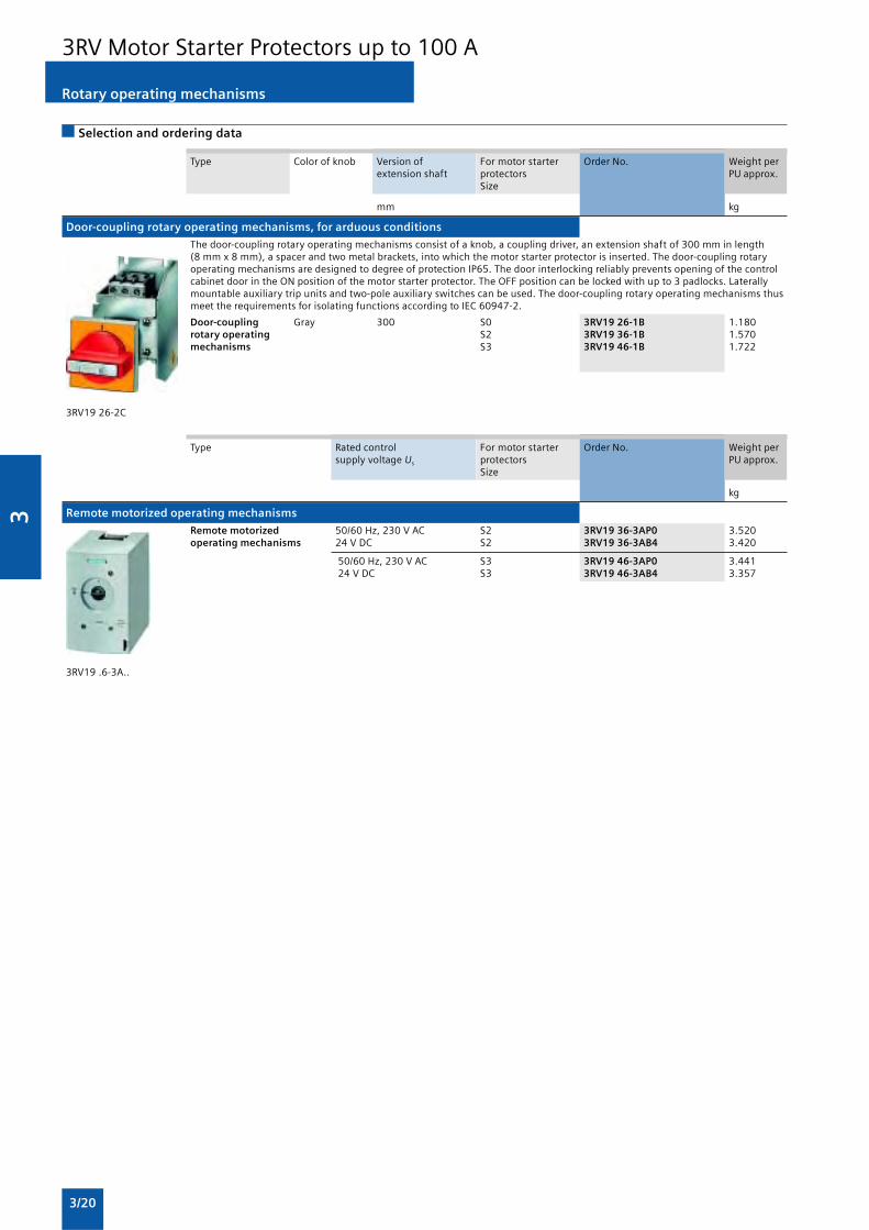
3
3/20
Selection and ordering data
Rotary operating mechanisms
3RV Motor Starter Protectors up to 100 A
Type Color of knob Version of For motor starter Order No. Weight perextension shaft protectors PU approx.
Size
mm kg
Door-coupling rotary operating mechanisms, for arduous conditions
The door-coupling rotary operating mechanisms consist of a knob, a coupling driver, an extension shaft of 300 mm in length(8 mm x 8 mm), a spacer and two metal brackets, into which the motor starter protector is inserted. The door-coupling rotaryoperating mechanisms are designed to degree of protection IP65. The door interlocking reliably prevents opening of the controlcabinet door in the ON position of the motor starter protector. The OFF position can be locked with up to 3 padlocks. Laterallymountable auxiliary trip units and two-pole auxiliary switches can be used. The door-coupling rotary operating mechanisms thusmeet the requirements for isolating functions according to IEC 60947-2.
Door-coupling Gray 300 S0 3RV19 26-1B 1.180rotary operating S2 3RV19 36-1B 1.570mechanisms S3 3RV19 46-1B 1.722
3RV19 26-2C
Type Rated control For motor starter Order No. Weight persupply voltage Us protectors PU approx.
Size
kg
Remote motorized operating mechanisms
Remote motorized 50/60 Hz, 230 V AC S2 3RV19 36-3AP0 3.520operating mechanisms 24 V DC S2 3RV19 36-3AB4 3.420
50/60 Hz, 230 V AC S3 3RV19 46-3AP0 3.441 24 V DC S3 3RV19 46-3AB4 3.357
3RV19 .6-3A..

3
3/21
Mounting accessories
3RV Motor Starter Protectors up to 100 A
Selection and ordering data
Version For motor starter Order No. Weight perprotectors PU approx.Size
kg
Covers
Terminal covers for box terminals S2 3RT19 36-4EA2 0.020Additional touch protection to be fitted S3 3RT19 46-4EA2 0.025at the box terminals(2 units mountable per device)
Terminal covers S3 3RT19 46-4EA1 0.040For cable lug and busbar connection For maintainingthe required voltage clearance and as touch protectionif box terminal is removed(2 units can be mounted per motor starter protector)
3RV1 (size S3) with Scale covers S00, S0, 3RV19 08-0P 0.1003RT19 46-4EA1 (left) Sealable, for covering the set current scale S2, S33RV19 08-0P (right)
Type Version For motor starter Order No. Weight perprotectors PU approx.Size
kg
Fixing accessories
Push-in lugs For screwing the motor starter protector S00, S0 3RB19 00-0B 0.100onto mounting plates. For each motorstarter protector, 2 units are required.
3RB19 00-0B
Version Method of Size Screw terminals Weight peroperation Contactors Motor starter PU approx.
protectors
Order No. kg
Link modules, single-unit packaging
For mechanical and electrical AC/DC S00 S00 3RA19 11-1AA00 0.027connection between contactor S00 S0 3RA19 21-1DA00 0.028and motor starter protector
AC S0 S0 3RA19 21-1AA00 0.037with screw terminals
S2 S2 3RA19 31-1AA00 0.042S3 S3 3RA19 41-1AA00 0.090
DC S0 S0 3RA19 21-1BA00 0.039S2 S2 3RA19 31-1BA00 0.043
3RA19 11-1AA00 S3 S3 3RA19 41-1BA00 0.089

3
3/22
Enclosures and front plates
3RV Motor Starter Protectors up to 100 A
Overview
Enclosures
For stand-alone installation of motor starter protectors of sizesS00 (In max = 12 A), S0 (In max = 25 A) and S2 (In max = 50 A),molded-plastic enclosures for surface mounting and molded-plastic enclosures for flush mounting are available in variousdimensions.
When installed in a molded-plastic enclosure the motor starterprotectors have a rated operational voltage Ue of 500 V.
The enclosures for surface mounting have the degree ofprotection IP55; the enclosures for flush mounting also complywith the degree of protection IP55 at the front (the flush-mounted section complies with IP20).
A mushroom-shaped EMERGENCY-STOP knob can be fitted inplace of the locking device. If it is actuated abruptly, the motorstarter protector opens and the mushroom-shaped knoblatches. The knob can be unlatched again either by turning it orby using a special key. The motor starter protector cansubsequently be switched on again.
The molded-plastic enclosures of S0 and S2 motor starterprotectors with rotary operating mechanism are fitted with arotary operating mechanism as well.
The enclosures can be supplied with a black rotary operatingmechanism or with an EMERGENCY-STOP rotary operatingmechanism with a red/yellow knob.
All rotary operating mechanisms can be locked in the openposition with up to 3 padlocks.
Front plates
Motor starter protectors are frequently required to be actuatedin any enclosure. Front plates equipped with an actuatordiaphragm for size S00 motor starter protectors, or rotaryoperating mechanism for S0 to S3 motor starter protectors areavailable for this purpose.
The front plates for size S00 have a holder into which themotor starter protectors can be snapped. A holder for size S0motor starter protectors is available for front plate sizes S0 toS3.
Enclosure for surface mounting
��
��
����
���
�
����
����
Enclosure for flush mounting
All enclosures are equipped with N- and PE- terminals. Thereare two knock-out cable entries for cable glands at the top andtwo at the bottom; also on the rear corresponding cable entriesare scored. There is a knockout on the top of the enclosure forindicator lights that are available as accessories.
The narrow enclosure can accommodate a motor starterprotector without accessories, with transverse and lateralauxiliary switch, whereas wide enclosures and enclosures forS2 motor starter protectors also provide space for a laterallymounted auxiliary trip unit. There is no provision for installinga motor starter protector with a signaling switch.
With S00 motor starter protectors, the switch rocker is operatedby means of the actuator diaphragm of the enclosure. Alocking device, capable of holding up to three padlocks, can befitted onto the actuator diaphragm to prevent the motor starterprotector from closing during maintenance work, for example.
��
��
���� �
Front plate for size S00
Accessories for enclosures and front plates
Accessories for size S00
��������� ����������"
����������! ����������#
��
��
����
��
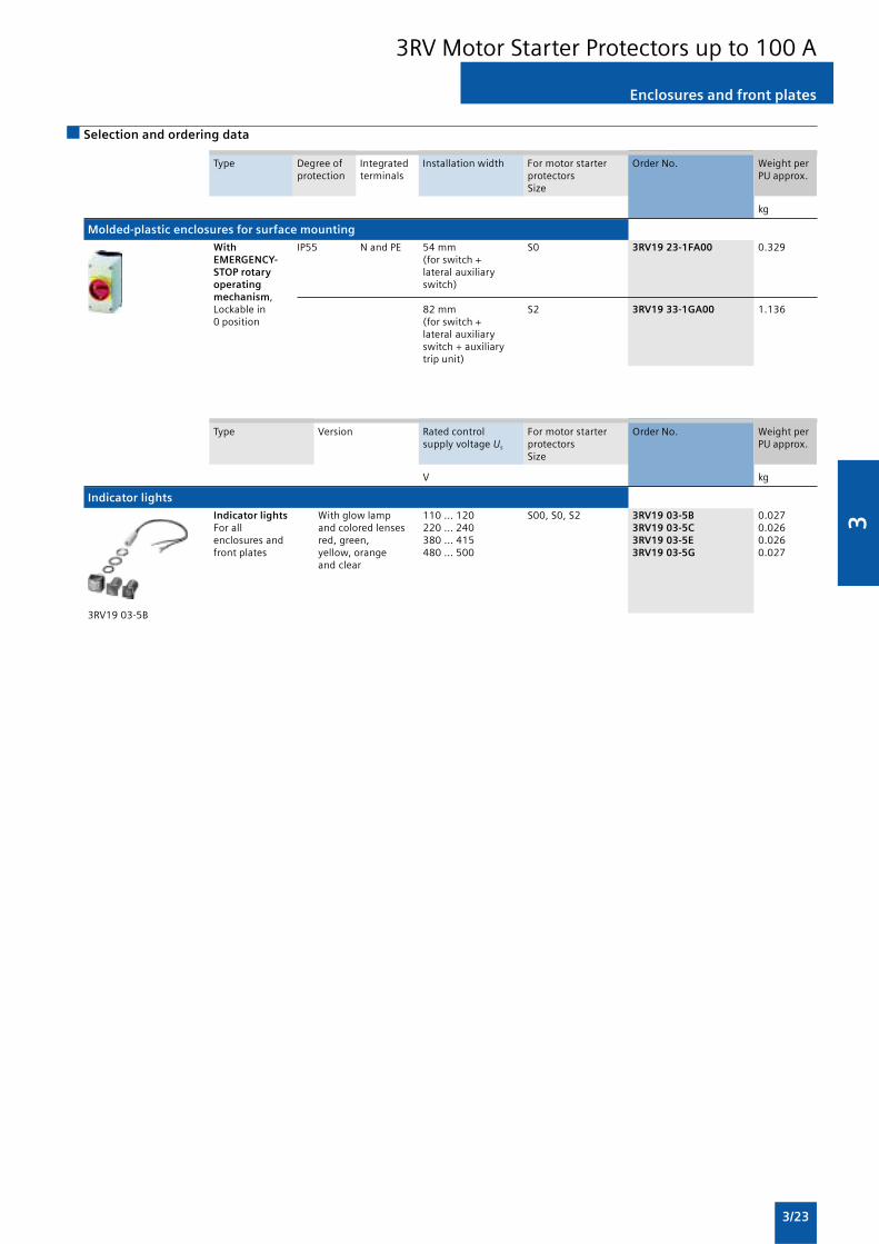
3
3/23
Enclosures and front plates
3RV Motor Starter Protectors up to 100 A
Selection and ordering data
Type Degree of Integrated Installation width For motor starter Order No. Weight perprotection terminals protectors PU approx.
Size
kg
Molded-plastic enclosures for surface mounting
With IP55 N and PE 54 mm S0 3RV19 23-1FA00 0.329EMERGENCY- (for switch +STOP rotary lateral auxiliaryoperating switch)mechanism,Lockable in 82 mm S2 3RV19 33-1GA00 1.1360 position (for switch +
lateral auxiliaryswitch + auxiliarytrip unit)
Type Version Rated control For motor starter Order No. Weight persupply voltage Us protectors PU approx.
Size
V kg
Indicator lights
Indicator lights With glow lamp 110 ... 120 S00, S0, S2 3RV19 03-5B 0.027For all and colored lenses 220 ... 240 3RV19 03-5C 0.026enclosures and red, green, 380 ... 415 3RV19 03-5E 0.026front plates yellow, orange 480 ... 500 3RV19 03-5G 0.027
and clear
3RV19 03-5B

3
3/24
General data
Overload Relays
Overview
1) Motor currents up to 820 A can be recorded and evaluated by a currentmeasuring module, e.g. 3RB29 06-2BG1 (0.3 ... 3 A) , in combinationwith a 3UF18 68-3GA00 (820 A / 1 A) series transformer.
2) The SIRIUS 3RN thermistor motor protection devices can be used toprovide additional protection temperature-dependent protection.
Features Benefits 3RU11 3RB20/3RB21 3RB22/3RB23
General data
Sizes • Are coordinated with the dimensions, connections S00 ... S3 S00 ... S12 S00 ... S12and technical characteristics of the other devicesin the SIRIUS modular system (contactors,soft starters, ...)
• Permit the mounting of slim and compact loadfeeders in widths of 45 mm (S00), 45 mm (S0),55 mm (S2), 70 mm (S3), 120 mm (S6) and145 mm (S10/S12)
• Simplify configuration
Seamless current range • Allows easy and consistent configuration with 0.11 ... 100 A 0.1 ... 630 A 0.3 ... 630 Aone series of overload relays ( ... 820 A)1)
(for small to large loads)
Protection functions
Tripping in the event of overload • Provides optimum inverse-time delayedprotection of loads against excessivetemperature rises due to overload
Tripping in the event of phase • Provides optimum inverse-time delayed ( )unbalance protection of loads against excessive
temperature rises due to phase unbalance
Tripping in the event of phase failure • Minimizes heating of induction motorsduring phase failure
Protection of single-phase loads • Enables the protection of single-phase loads —
Tripping in the event of overheating • Provides optimum temperature-dependent —2) —2)
protection of loads against excessive temperatureby rises, e.g. for stator-critical motors or in the eventIntegrated thermistor motor of insufficient coolant flow, contamination ofprotection function the motor surface or for long starting or
braking operations
• Eliminates the need for additional specialequipment
• Saves space in the control cabinet
• Reduces wiring outlay and costs
Tripping in the event of a ground • Provides optimum protection of loads against —fault high-resistance short-circuits or ground faults (only 3RB21)
due to moisture, condensed water, damage toby the insulation material, etc.
Internal ground fault detection • Eliminates the need for additional special
(activatable) equipment.
• Saves space in the control cabinet
• Reduces wiring outlay and costs
Features
RESET function • Allows manual or automatic resetting of the relay
Remote RESET function • Allows the remote resetting of the relay(by means of (only 3RB21separate module) with 24 V DC)
TEST function for auxiliary contacts • Allows easy checking of the function and wiring
TEST function for electronics • Allows checking of the electronics —
Status displays • Displays the current operating state
Large current adjustment button • Makes it easier to set the relay exactly to thecorrect current value
Integrated auxiliary contacts • Allows the load to be switched off if necessary(1 NO + 1 NC) • Can be used for signal output
(2 ·)

3
3/25
General data
Overload Relays
1) Exception: up to size S3, only stand-alone installation is possible.
2) Alternatively available for screw terminals.
Features Benefits 3RU11 3RB20/3RB21 3RB22/3RB23
Design of load feeders
Short-circuit strength up to 100 kA • Provides optimum protection of the loads andat 690 V operating personnel in the event of short-circuits(in conjunction with the corresponding due to insulation faults or faulty switchingfuses or the corresponding motor operationsstarter protector)
Electrical and mechanical matching • Simplifies configuration 1)
to 3RT1 contactors • Reduces wiring outlay and costs
• Enables stand-alone installation as well asspace-saving direct mounting
Straight-through transformers for • Reduces the contact resistance —main circuit2) (only one point of contact) (S2 ... S6) (S00 ... S6)(in this case the cables are routed • Saves wiring coststhrough the feed-through openings of the (easy, no need for tools, and fast).overload relay and connected directly
• Saves material coststo the box terminals of the contactor)• Reduces installation costs
Spring-loaded terminal connection • Enables fast connections — —system for main circuit2)
• Permits vibration-resistant connections (S00)
• Enables maintenance-free connections
Spring-loaded terminal connection • Enables fast connectionssystem for auxiliary circuits2)
• Permits vibration-resistant connections
• Enables maintenance-free connections
Other features
Temperature compensation • Allows the use of the relays at hightemperatures without derating
• Prevents premature tripping
• Allows compact installation of the control cabinetwithout distance between the units/load feeders
• Simplifies configuration
• Enables space to be saved in the control cabinet
Very high long-term stability • Provides safe protection for the loads even after ( )years of use in severe operating conditions
Wide setting ranges • Reduce the number of variants
• Minimize the engineering outlay and costs
• Reduce storage overhead, storage costs, —tied-up capital (1:4) (1:10)
Trip class CLASS 5 • Enables solutions for very fast starting motors —requiring special protection (e.g. Ex motors) (only 3RB21)
Trip class > CLASS 10 • Enable heavy starting solutions —
Low power loss • Reduces power consumption and energy costs —(up 98% less power is used than for thermaloverload relays).
• Minimizes temperature rises of the contactorand control cabinet – in some cases this mayeliminate the need for control cabinet cooling.
• Direct mounting to contactor saves space, evenfor high motor currents(i.e. no heat decoupling is required)

3
3/26
1) The SIRIUS 3RU11 thermal overload relays use a bimetal contactor andtherefore do not require a control supply voltage.
General data
Overload Relays
Features Benefits 3RU11 3RB20/3RB21 3RB22/3RB23
Other features
Internal power supply • Eliminates the need for configuration and —1) —connecting an additional control circuit
Variable adjustment of the trip classes • Reduces the number of variants —(The required trip class can be adjusted • Minimizes the configuring outlay and costs (only 3RB21)by means of a rotary switch depending
• Minimizes storage overhead, storage costs,on the current start-up condition.)and tied-up capital
Overload warning • Indicates imminent tripping of the relay directly — —on the device due to overload, phase unbalanceor phase failure
• Allows the imminent tripping of the relay to besignaled
• Allows measures to be taken in time in theevent of continuous inverse-time delayedoverloads
• Eliminates the need for an additional device
• Saves space in the control cabinet
• Reduces wiring outlay and costs
Analog output • Allows the output of an analog output signal — —for actuating moving-coil instruments, feedingprogrammable logic controllers or transfer tobus systems
• Eliminates the need for an additionalmeasuring transformer and signal converter
• Saves space in the control cabinet
• Reduces wiring outlay and costs

3
3/27
General data
Overload Relays
Connection methods
The 3RB20/3RB21 relays are available with screw terminals (boxterminals) on the auxiliary current side; the same applies forthe evaluation modules of the 3RB22/3RB23 relays. The 3RU11relays come with screw terminals.
Overload Current Current Contactors (type, size, rating in kW)relays measurement range 3RT10 1 3RT10 2 3RT10 3 3RT10 4 3RT10 5 3RT10 6 3RT10 7 3TF68/69
S00 S0 S2 S3 S6 S10 S12 Size 14
Type Type A 3/4/5.5 5.5/7.5/11 15/18.5/22 30/37/45 55/75/90 110/132/160 200/250 375/450
3RU11 thermal overload relays
3RU11 1 Integrated 0.11 … 12 — — — — — — —
3RU11 2 Integrated 1.8 … 25 — — — — — — —
3RU11 3 Integrated 5.5 … 50 — — — — — — —
3RU11 4 Integrated 18 … 100 — — — — — — —
3RB20 solid-state overload relays
3RB20 1 Integrated 0.1 … 12 — — — — — — —
3RB20 2 integrated 0.1 … 25 — — — — — — —
3RB20 3 Integrated 6 … 50 — — — — — — —
3RB20 4 Integrated 12.5 … 100 — — — — — — —
3RB20 5 Integrated 50 ... 200 — — — — — — —
3RB20 6 Integrated 55 ... 630 — — — — —
3RB20 1 + Integrated 630 ... 820 — — — — — — —3UF18
3RB21 solid-state overload relays
3RB21 1 Integrated 0.1 … 12 — — — — — — —
3RB21 2 Integrated 0.1 … 25 — — — — — — —
3RB21 3 Integrated 6 … 50 — — — — — — —
3RB21 4 Integrated 12.5 … 100 — — — — — — —
3RB21 5 Integrated 50 ... 200 — — — — — — —
3RB21 6 Integrated 55 ... 630 — — — — —
3RB21 1 + Integrated 630 ... 820 — — — — — — —3UF18
3RB22/3RB23 solid-state overload relays
3RB29 0 0.3 … 25 — — — — — —
3RB29 0 10 ... 100 — — — — — —
3RB22/3RB23 + 3RB29 5 20 … 200 — — — — — — —
3RB29 6 63 ... 630 — — — — —
3RB29 0 + 630 ... 820 — — — — — — —3UF18

3
3/28
General data
Overload Relays
Conversion aid 3RB12 ––> 3RB22/3RB23
Previous typesReplacement types
Size Overload relays (complete units) Current measuring module Evaluation module Function expansionmodule
3RB12 Setting range in A 3RB29 Setting range in A 3RB22/3RB23 3RB29
3RB29 06-2BG11) 0.3 ... 3S00/S0 3RB12 46-1P 1.25 ... 6.3
3RB29 06-2DG11) 2.4 ... 253RB12 46-1Q 6.3 ... 25
S2/S3 3RB12 46-1E 25 ... 100 3RB29 06-2JG11) 10 ... 100 3RB2 83-4AA1 3RB29 85-2
S6 3RB12 53-0F 50 ... 205 3RB29 56-2TG22) 20 ... 200
3RB29 56-2TH22)
S10/S12 3RB12 57-0K 125 ... 500 3RB29 66-2WH22) 63 ... 630 (820)3)
3RB12 62-0L 200 ... 820
110 ... 120 V AC G
220 ... 240 V AC M
24 V DC B
Standard version with 0 0 — —ground-fault signaling
Standard version with 1 0 2overload warning
Version with internal 2 0 2 CB1ground fault detectionand ground-faultsignaling
Version with internal 3 0 2 CA1ground fault detectionand overload warning
Version with analog output 4 0 2 AA0
Bistable version with 0 1 — —ground-fault signaling
Bistable version with 1 1 3overload warning
1) Use 3RB29 87-2B connecting cable.
2) Use 3RB29 87-2D connecting cable.
3) Motor currents up to 820 A can be recorded and evaluated by a currentmeasuring module, e.g. 3RB29 06-2BG1 (0.3 ... 3 A), in combination witha 3UF18 68-3GA00 (820 A / 1 A) series transformer.
= Included in the evaluation module (no selection)
— = Not available

3
3/29
3RB20, 3RB21 for standard applications
Overload Relays
Overview
(1) Connection for mounting onto contactors:Optimally adapted in electrical, mechanical and design terms to thecontactors and soft starters, these connecting pins can be used fordirect mounting of the overload relays. Stand-alone installation ispossible as an alternative (in some cases in conjunction with a stand-alone installation module).
(2) Selector switch for manual/automatic RESET and RESET button:With the slide switch you can choose between manual andautomatic RESET. A device set to manual RESET can be reset locallyby pressing the RESET button. On the 3RB21 a solid-state remoteRESET is integrated.
(3) Switch position indicator and TEST function of the wiring:Indicates a trip and enables the wiring test.
(4) Solid-state test (device test):Enables a test of all important device components and functions.
(5) Motor current setting:Setting the device to the rated motor current is easy with the largerotary knob.
(6) Trip class setting/internal ground-fault detection (only 3RB21):Using the rotary switch you can set the required trip class andactivate the internal ground-fault detection dependent on the start-up conditions.
(7) Connecting terminals (removable terminal block for auxiliarycircuits):The generously sized terminals permit connection of two conductorswith different cross-sections for the main and auxiliary circuits. Theauxiliary circuit can be connected with screw connection andalternatively with spring-type connection.
The 3RB20 and 3RB21 solid-state overload relays up to 630 Awith internal power supply have been designed for inverse-time delayed protection of loads with normal and heavystarting against excessive temperature rises due to overload,phase unbalance or phase failure. An overload, phaseunbalance or phase failure result in an increase of the motorcurrent beyond the set rated motor current. This current rise isdetected by the current transformers integrated into thedevices and evaluated by corresponding solid-state circuitswhich then output a pulse to the auxiliary contacts. Theauxiliary contacts then switch off the load by means of acontactor. The break time depends on the ratio between thetripping current and set current Ie and is stored in the form of along-term stable tripping characteristic.
In addition to inverse-time delayed protection of loads againstexcessive temperature rises due to overload, phase unbalanceand phase failure, the 3RB21 solid-state overload relays alsoallow internal ground-fault detection (not possible inconjunction with wye-delta assemblies). This providesprotection of loads against high-resistance short-circuits due todamage to the insulation material, moisture, condensed wateretc.
The “tripped” status is signaled by means of a switch positionindicator. Resetting takes place either manually orautomatically after the recovery time has elapsed.
The devices are manufactured in accordance withenvironmental guidelines and contain environmentally friendlyand reusable materials. They comply with all importantworldwide standards and approvals.
“Increased safety” type of protection EEx e according toATEX directive 94/9/EC
The 3RB20/3RB21 solid-state overload relays are suitable forthe overload protection of explosion-proof motors with“increased safety” type of protection EEx e. The relays meet therequirements of EN 60079-7 (Electrical apparatus for areassubject to explosion hazards – Increased safety “e”);
EC type test certificate for Group II, Category (2) G/D exists. Ithas the number PTB 06 ATEX 3001.

3
3/30
3RB20, 3RB21 for standard applications
Overload Relays
Application
Industries
The 3RB20/3RB21 solid-state overload relays are suitable forcustomers from all industries who want to guarantee optimuminverse-time delayed protection of their electrical loads (e.g.motors) under normal and heavy starting conditions (CLASS 5to CLASS 30), minimize project completion times, inventoriesand power consumption, and optimize plant availability andmaintenance management.
Application
The 3RB20/3RB21 solid-state overload relays have beendesigned for the protection of induction motors in sinusoidal50/60 Hz voltage networks. The relays are not suitable for theprotection of single-phase AC or DC loads.
The 3RU11 thermal overload relay or the 3RB22/3RB23 solid-state overload relay can be used for single-phase AC loads. ForDC loads we recommend the 3RU11 thermal overload relay.
Ambient conditions
The devices are insensitive to external influences such asshocks, corrosive environments, ageing and temperaturefluctuation.
For the temperature range from –25 C to +60 °C, the 3RB20/3RB21 solid-state overload relays compensate the temperatureaccording to IEC 60947-4-1.
For the 3RB20/3RB21 solid-state overload relays with the sizesS6, S10 and S12, the upper set value of the setting range mustbe reduced for ambient temperatures > 50 °C by a certainfactor (see tables below).
Type Setting range Derating factor for the upper setvalue for stand-alone installationat ambient temperature
+50 °C +60 °C
3RB20 56, 3RB21 56 50 ... 200 A 100 % 100 %
3RB20 66, 3RB21 66 55 ... 250 A 100 % 100 %
3RB20 66, 3RB21 66 160 ... 630 A 100 % 90 %
Type Setting range Derating factor for the upper setvalue for mounting onto contactorat ambient temperature
+50 °C +60 °C
3RB20 56, 3RB21 56 50 ... 200 A 100 % 70 %
3RB20 66, 3RB21 66 55 ... 250 A 100 % 70 %
3RB20 66, 3RB21 66 160 ... 630 A 100 % 70 %
Accessories
The following accessories are available for the 3RB20/3RB21solid-state overload relays:
• One terminal bracket each for the overload relays size S00and S0 (sizes S2 to S12 can be installed as single unitswithout a terminal bracket)
• One mechanical remote RESET module for all sizes
• One cable release for resetting devices which are difficult toaccess (for all sizes)
• One sealable cover for all sizes
• Box terminal blocks for sizes S6 and S10/S12
• Terminal covers for sizes S2 to S10/S12

3
3/31
3RB20, 3RB21 for standard applications
Overload Relays
Selection and ordering data
3RB20 solid-state overload relays with screw terminals on auxiliary current side for direct mounting1)2) and stand-aloneinstallation2)3), CLASS 10
Features and technical specifications:• Overload protection, phase failure protection and unbalance
protection• Internal power supply• Auxiliary contacts 1 NO + 1 NC
• Manual and automatic RESET• Switch position indicator• TEST function and self-monitoring
1) The relays with an Order No. ending with “0” are designed for directmounting. With the matching terminal brackets (see “Accessories”, page5/38),the sizes S00 and S0 can also be installed as stand-alone units.
2) The relays with an Order No. ending with “2” are designed for directmounting and stand-alone installation. For 3TF68/3TF69 contactors,direct mounting is not possible.
3) The relays with an Order No. ending with “1” are designed for stand-alone installation.
4) Observe maximum rated operational current of the devices.5) Guide value for 4-pole standard motors at 50 Hz 400 V AC. The actual
starting and rated data of the motor to be protected must be consideredwhen selecting the units.
6) Maximum fuse for overload relay, type of coordination 2.7) The relays with an Order No. with “W” in penultimate position are
equipped with a straight-through transformer.
Size of Rating for Set current value Short-circuit protection Screw terminals Weight percontactor4) induction motor of the inverse-time with fuse, type of (on auxiliary current side) PU approx.
Rated value5) delayed overload coordination 2, gL/gGrelease operational class6) Order No.
kW A A kg
Size S001)
S00 0.04 … 0.09 0.1 … 0.4 1 3RB20 16-1RB0 0.200
0.12 … 0.37 0.32 … 1.25 2 3RB20 16-1NB0 0.200
0.55 … 1.5 1 … 4 10 3RB20 16-1PB0 0.200
1.1 … 5.5 3 … 12 20 3RB20 16-1SB0 0.200
3RB20 16-1RB0
Size S01)
S0 0.04 … 0.09 0.1 … 0.4 1 3RB20 26-1RB0 0.220
0.12 … 0.37 0.32 … 1.25 2 3RB20 26-1NB0 0.220
0.55 … 1.5 1 … 4 10 3RB20 26-1PB0 0.220
1.1 … 5.5 3 … 12 20 3RB20 26-1SB0 0.220
3 … 11 6 … 25 35 3RB20 26-1QB0 0.220
3RB20 26-1QB0
Size S21)3)7)
S2 3 … 11 6 … 25 63 3RB20 36-1QB0 0.360
3RB20 36-1QW1 0.230
7.5 … 22 12.5 … 50 80 3RB20 36-1UB0 0.360
3RB20 36-1UW1 0.230
3RB20 36-1UB0
Size S31)3)7)
S3 7.5 … 22 12.5 … 50 160 3RB20 46-1UB0 0.560
11 … 45 25 … 100 315 3RB20 46-1EB0 0.560
3RB20 46-1EW1 0.450
3RB20 46-1EB0
Size S6 2)7)
S6 with 22 … 90 50 … 200 315 3RB20 56-1FC2 1.030busbarconnection
S6 3RB20 56-1FW2 0.690with boxterminals
3RB20 56-1FW2
Size S10/S122)
S10/S12 22 … 110 55 … 250 400 3RB20 66-1GC2 1.820and 90 … 450 160 … 630 800 3RB20 66-1MC2 1.820size 14(3TF68/3TF69)
3RB20 66-1MC2

3
3/32
3RB20, 3RB21 for standard applications
Overload Relays
3RB20 solid-state overload relays with screw terminals on auxiliary current side for direct mounting1)2) and stand-aloneinstallation2)3), CLASS 20
Features and technical specifications:• Overload protection, phase failure protection and unbalance
protection
• Internal power supply
• Auxiliary contacts 1 NO + 1 NC
• Manual and automatic RESET
• Switch position indicator
• TEST function and self-monitoring
Size of Rating for Set current value Short-circuit protection Screw terminals Weight percontactor4) induction motor of the inverse-time with fuse, type of (on auxiliary current side) PU approx.
Rated value5) delayed overload coordination 2, gL/gGrelease operational class6) Order No.
kW A A kg
Size S001)
S00 0.04 … 0.09 0.1 … 0.4 1 3RB20 16-2RB0 0.200
0.12 … 0.37 0.32 … 1.25 2 3RB20 16-2NB0 0.200
0.55 … 1.5 1 … 4 10 3RB20 16-2PB0 0.200
1.1 … 5.5 3 … 12 20 3RB20 16-2SB0 0.200
3RB20 16-2RB0
Size S01)
S0 0.04 ... 0.09 0.1 ... 0.4 1 3RB20 26-2RB0 0.220
0.12 ... 0.37 0.32 ... 1.25 2 3RB20 26-2NB0 0.220
0.55 ... 1.5 1 ... 4 10 3RB20 26-2PB0 0.220
1.1 … 5.5 3 … 12 20 3RB20 26-2SB0 0.220
3 … 11 6 … 25 35 3RB20 26-2QB0 0.220
3RB20 26-2QB0
Size S21)3)7)
S2 3 … 11 6 … 25 63 3RB20 36-2QB0 0.360
3RB20 36-2QW1 0.230
7.5 … 22 12.5 … 50 80 3RB20 36-2UB0 0.360
3RB20 36-2UW1 0.230
3RB20 36-2UB0
Size S31)3)7)
S3 7.5 … 22 12.5 … 50 160 3RB20 46-2UB0 0.560
11 … 45 25 … 100 315 3RB20 46-2EB0 0.560
3RB20 46-2EW1 0.450
3RB20 46-2EB0
Size S62)7)
S6 with 22 … 90 50 … 200 315 3RB20 56-2FC2 1.030busbarconnection
S6 3RB20 56-2FW2 0.690with boxterminals
3RB20 56-2FW2
Size S10/S122)
S10/S12 22 … 110 55 … 250 400 3RB20 66-2GC2 1.820and 90 … 450 160 … 630 800 3RB20 66-2MC2 1.820size 14(3TF68/3TF69)
3RB20 66-2MC2
1) The relays with an Order No. ending with “0” are designed for directmounting. With the matching terminal brackets (see “Accessories”, page5/38) the sizes S00 and S0 can also be installed as stand-alone units.
2) The relays with an Order No. ending with “2” are designed for directmounting and stand-alone installation. For 3TF68/3TF69 contactors,direct mounting is not possible.
3) The relays with an Order No. ending with “1” are designed for stand-alone installation.
4) Observe maximum rated operational current of the devices.
5) Guide value for 4-pole standard motors at 50 Hz 400 V AC. The actualstarting and rated data of the motor to be protected must be consideredwhen selecting the units.
6) Maximum fuse for overload relay, type of coordination 2.
7) The relays with an Order No. with “W” in penultimate position areequipped with a straight-through transformer.

3
3/33
3RB20, 3RB21 for standard applications
Overload Relays
3RB21 solid-state overload relays with screw terminals on auxiliary current side for direct mounting1)2) and stand-aloneinstallation2)3), CLASS 5, 10, 20 and 30 adjustable
Features and technical specifications:• Overload protection, phase failure protection and unbalance
protection• Internal ground fault detection (activatable)• Internal power supply• Auxiliary contacts 1 NO + 1 NC
• Manual and automatic RESET• Electrical remote RESET integrated• Switch position indicator• TEST function and self-monitoring
1) The relays with an Order No. ending with “0” are designed for directmounting. With the matching terminal brackets (see “Accessories”, page5/38) the sizes S00 and S0 can also be installed as stand-alone units.
2) The relays with an Order No. ending with “2” are designed for directmounting and stand-alone installation. For 3TF68/3TF69 contactors,direct mounting is not possible.
3) The relays with an Order No. ending with “1” are designed for stand-alone installation.
4) Observe maximum rated operational current of the devices.
5) Guide value for 4-pole standard motors at 50 Hz 400 V AC. The actualstarting and rated data of the motor to be protected must be consideredwhen selecting the units.
6) Maximum fuse for overload relay, type of coordination 2.
7) The relays with an Order No. with “W” in penultimate position areequipped with a straight-through transformer.
Size of Rating for Set current value Short-circuit protection Screw terminals Weight percontactor4) induction motor of the inverse-time with fuse, type of (on auxiliary current side) PU approx.
Rated value5) delayed overload coordination 2, gL/gGrelease operational class6) Order No.
kW A A kg
Size S001)
S00 0.04 … 0.09 0.1 … 0.4 1 3RB21 13-4RB0 0.200
0.12 … 0.37 0.32 … 1.25 2 3RB21 13-4NB0 0.200
0.55 … 1.5 1 … 4 10 3RB21 13-4PB0 0.200
1.1 … 5.5 3 … 12 20 3RB21 13-4SB0 0.200
3RB21 13-4RB0
Size S01)
S0 0.04 … 0.09 0.1 … 0.4 1 3RB21 23-4RB0 0.220
0.12 … 0.37 0.32 … 1.25 2 3RB21 23-4NB0 0.220
0.55 ... 1.5 1 ... 4 10 3RB21 23-4PB0 0.220
1.1 … 5.5 3 … 12 20 3RB21 23-4SB0 0.220
3 … 11 6 … 25 35 3RB21 23-4QB0 0.220
3RB21 23-4QB0
Size S21)3)7)
S2 3 … 11 6 … 25 63 3RB21 33-4QB0 0.360
3RB21 33-4QW1 0.230
7.5 … 22 12.5 … 50 80 3RB21 33-4UB0 0.360
3RB21 33-4UW1 0.230
3RB21 33-4UB0
Size S31)3)7)
S3 7.5 … 22 12.5 … 50 160 3RB21 43-4UB0 0.560
11 … 45 25 … 100 315 3RB21 43-4EB0 0.560
3RB21 43-4EW1 0.450
3RB21 43-4EB0
Size S62)7)
S6 with 22 … 90 50 … 200 315 3RB21 53-4FC2 1.030busbarconnection
S6 3RB21 53-4FW2 0.690with boxterminals
3RB21 53-4FC2
Size S10/S122)
S10/S12 22 … 110 55 … 250 400 3RB21 63-4GC2 1.820and size 14 90 … 450 160 … 630 800 3RB21 63-4MC2 1.820(3TF68/3TF69)
3RB21 63-4MC2

3
3/34
3RB22, 3RB23 for high-feature applications
Overload Relays
Overview
3RB22/3RB23 evaluation module
(1) Green “READY” LED:A continuous green light signals that the device is working correctly.
(2) Red “GND FAULT” LED:A continuous red light signals a ground-fault tripping.
(3) Red “THERMISTOR” LED:A continuous red light signals an active thermistor trip.
(4) Red “OVERLOAD” LED:A continuous red light signals an active overload trip; a flickering redlight signals an imminent trip (overload warning).
(5) Motor current and trip class adjustment:Setting the device to the motor current and to the required trip classdependent on the start-up conditions is easy with the two rotaryswitches.
(6) Selector switch for manual/automatic RESET:With this switch you can choose between manual and automaticRESET.
(7) Test/RESET button:Enables testing of all important device components and functions,plus resetting of the device after a trip when manual RESET isselected.
(8) Connecting terminals (removable terminal block):The generously sized terminals permit connection of two conductorswith different cross-sections for the auxiliary, control and sensorcircuits. Connection is possible with screw connection andalternatively with spring-type connection.
(9) 3RB29 85 function expansion module:Enables more functions to be added, e.g. internal ground faultdetection and/or an analog output with corresponding signals.
3RB29 06 current measuring module
The modular, solid-state overload relays with external powersupply type 3RB22 (with monostable auxiliary contacts) andtype 3RB23 (with bistable auxiliary contacts) up to 630 A (upto 820 A possible with a series transformer) have beendesigned for inverse-time delayed protection of loads withnormal and heavy starting against excessive temperature risesdue to overload, phase unbalance or phase failure. Anoverload, phase unbalance or phase failure result in anincrease of the motor current beyond the set rated motorcurrent. This current rise is detected by means of a currentmeasuring module and electronically evaluated by a specialevaluation module which is connected to it. The evaluationelectronics sends a signal to the auxiliary contacts. Theauxiliary contacts then switch off the load by means of acontactor. The break time depends on the ratio between thetripping current and set current Ie and is stored in the form of along-term stable tripping characteristic. The “tripped” status issignaled by means of a continuous red “OVERLOAD” LED.
The LED indicates imminent tripping of the relay due tooverload, phase unbalance or phase failure by flickering whenthe limit current has been violated. This warning can alsoissued as a signal through auxiliary contacts.
In addition to the described inverse-time delayed protection ofloads against excessive temperature rises, the 3RB22/3RB23solid-state overload relays also allow direct temperaturemonitoring of the motor windings (full motor protection) byconnection with broken-wire interlock of a PTC sensor circuit.With this temperature- dependent protection, the loads can beprotected against overheating caused indirectly by reducedcoolant flow, for example, which cannot be detected by meansof the current alone. In the event of overheating, the devicesswitch off the contactor, and thus the load, by means of theauxiliary contacts. The “tripped” status is signaled by means ofa continuously illuminated “THERMISTOR” LED.
To also protect the loads against high-resistance short-circuitsdue to damage to the insulation, humidity, condensed water,etc., the 3RB22/3RB23 solid-state overload relays offer thepossibility of internal ground fault monitoring in conjunctionwith a function expansion module not possible in conjunctionwith contactor assembly for Wye-Delta starting). In the eventof a ground fault, the 3RB22/3RB23 relays trip instantaneously.The “tripped” status is signaled by means of a continuous red“Ground Fault” LED. Signaling through auxiliary contacts is alsopossible.
After tripping due to overload, phase unbalance, phase failure,thermistor tripping or ground fault, the relay is reset manuallyor automatically after the recovery time has elapsed
In conjunction with a function expansion module, the motorcurrent measured by the microprocessor can be output in theform of an analog signal 4 ... 20 mA DC for operating rotarycoil instruments or for feeding into analog inputs ofprogrammable logic controllers. With an additional AS-Interface analog module, the current values can also betransferred over the AS-i bus system.
The devices are manufactured in accordance withenvironmental guidelines and contain environmentally friendlyand reusable materials.
They comply with all important worldwide standards andapprovals.

3
3/35
3RB22, 3RB23 for high-feature applications
Overload Relays
“Increased safety” type of protection EEx e according toATEX directive 94/9/EC
The 3RB22 (monostable) solid-state overload relays are suitablefor the overload protection of explosion-proof motors with“Increased safety” type of protection EEx e. The relays meet therequirements of EN 60079-7 (Electrical apparatus for areassubject to explosion hazards – Increased safety “e”);
EC type test certificate for Group II, Category (2) G/D exists. Ithas the number PTB 05 ATEX 3022.
Application
Industries
The 3RB22/3RB23 solid-state overload relays are suitable forcustomers from all industries who want to guarantee optimuminverse-time delayed and temperature-dependent protection oftheir electrical loads (e.g. motors) under normal and heavystarting conditions (CLASS 5 to CLASS 30), minimize projectcompletion times, inventories and power consumption, andoptimize plant availability and maintenance management.
Application
The 3RB22/3RB23 solid-state overload relays have beendesigned for the protection of three-phase asynchronous andsingle-phase AC motors.
If single-phase AC motors are to be protected by the 3RB22/3RB23 solid-state overload relays, the main current paths ofthecurrent measuring modules must be series-connected
Ambient conditions
The devices are insensitive to external influences such asshocks, corrosive environments, ageing and temperaturefluctuation.
For the temperature range from –25 C to +60 °C, the 3RB22/3RB23 solid-state overload relays compensate the temperatureaccording to IEC 60947-4-1.
Configuration notes for use of the devices below –25 °C orabove +60 °C on request.
Accessories
The following accessories are available for the 3RB22/3RB23solid-state overload relays:
• A sealable cover for the evaluation module
• Box terminal blocks for the current measuring modules sizeS6 and S10/S12
• Terminal covers for the current measuring modules size S6and S10/S12
• Push-in lugs for screw mounting the size S00 to S3 currentmeasuring modules

3
3/36
Selection and ordering data
3RB22/3RB23 solid-state overload relays for full motor protection with screw terminals or spring-loaded terminals forstand-alone installation, CLASS 5, 10, 20 and 30 adjustable
Features and technical specifications:
3RB22, 3RB23 for high-feature applications
Overload Relays
• Overload protection, phase failure protection and unbalanceprotection
• External power supply 24 ... 240 V AC/DC
• Auxiliary contacts 2 NO + 2 NC
• Manual and automatic RESET
• Electrical remote RESET integrated
• 4 LEDs for operating and status displays
• TEST function and self-monitoring
• Internal ground fault detection with function expansionmodule
• Screw terminals or spring-loaded terminals for auxiliary,control and sensor circuits
• Input for PTC sensor circuit
• Analog output with function expansion module
Size of Version Screw terminals Weight percontactor PU approx.
Order No. kg
Evaluation modules
S00 ... S12 Monostable 3RB22 83-4AA1 0.300
Bistable 3RB23 83-4AA1 0.300
3RB2. 83-4AA1
Size of Version Order No. Weight percontactor PU approx.
kg
Function expansion modules
For plugging into evaluation module (1 unit)
S00 ... S12 Analog Basic 11) modules 3RB29 85-2AA0 0.030Analog output DC 4 ... 20 mA, with overload warning
Analog Basic 1 GF1)2) modules 3RB29 85-2AA1 0.030Analog output DC 4 ... 20 mA,with internal ground fault detection and overload warning
Analog Basic 2 GF1)2) modules 3RB29 85-2AB1 0.030Analog output DC 4 ... 20 mA,with internal ground fault detection and ground-fault signaling
Basic 1 GF2) modules 3RB29 85-2CA1 0.030with internal ground fault detection and overload warning
Basic 2 GF2) modules 3RB29 85-2CB1 0.030with internal ground fault detection and ground-fault signaling
Note: Analog input modules, e.g. SM 331, must be configuredfor 4-wire measuring transducers. In this case the analog inputmodule must not supply current to the analog output of the3RB22/ 3RB23 relay.
1) The analog signal DC 4 ... 20 mA can be used for operating rotary coilinstruments or for feeding into analog inputs of programmable logiccontrollers.
2) The following information on ground-fault protection refers to sinusoidalresidual currents at 50/60 Hz:
- with a motor current of between 0.3 and 2 times the set current Ie theunit will trip at a ground-fault current equal to 30 % of the set current.
- with a motor current of between 2 and 8 times the set current Ie theunit will trip at a ground-fault current equal to 15 % of the set current.
- the response delay amounts to between 0.5 and 1 second.

3
3/37
3RB22, 3RB23 for high-feature applications
Overload Relays
Current measuring modules for direct mounting1) and stand-alone installation1)2)
Size of Rating for Set current value Short-circuit protection Order No. Weight percontactor3) induction motor of the inverse-time with fuse, type of PU approx.
Rated value4) delayed overload coordination 2, gL/gGrelease operational class5)
kW A kg
Size S00/S0 2)6)
S00/S0 0.09 … 1.1 0.3 … 3 20 3RB29 06-2BG1 0.100
1.1 … 11 2.4 … 25 63 3RB29 06-2DG1 0.150
3RB29 06-2.G1
Size S2/S3 2)6)
S2/S3 5.5 … 45 10 … 100 315 3RB29 06-2JG1 0.350
3RB29 06-2JG1
Size S61)6)
S6 with 11 … 90 20 … 200 315 3RB29 56-2TH2 1.000busbarconnection
S6 3RB29 56-2TG2 0.600with boxterminals
3RB29 56-2TG2
Size S10/S121)
S10/S12 37 … 450 63 … 630 800 3RB29 66-2WH2 1.750andsize 14(3TF68/3TF69)
3RB29 66-2WH2
Note: The connecting cable between the current measuringmodule and the evaluation module is not included in thescope of supply; please order separately.1) The current measuring modules with an Order No. ending with “2” are
designed for direct mounting and stand-alone installation.For 3TF68/3TF69 contactors, direct mounting is not possible.
2) The current measuring modules with an Order No. ending with “1” aredesigned for stand-alone installation.
3) Observe maximum rated operational current of the devices.
4) Guide value for 4-pole standard motors at 50 Hz 400 V AC. The actualstarting and rated data of the motor to be protected must be consideredwhen selecting the units.
5) Maximum protection by fuse for overload relay, type of coordination 2.
6) The modules with an Order No. with “G” in penultimate position areequipped with a straight-through transformer.
Accessories
Size of Version Order No. Weight percontactor PU approx.
kg
Connecting cables (essential accessory)
For connection between evaluation module and currentmeasuring module
S00 ... S3 • Length 0.1 m 3RB29 87-2B 0.010(only for mounting of the evaluation module directlyonto the current measuring module)
S00 ... S12 • Length 0.5 m 3RB29 87-2D 0.020
3RB29 87-2.
For more accessories, see page 3/38.

3
3/38
Accessories
Overload Relays
Overview
Overload relays for standard applications
The following optional accessories are available for the 3RB20/3RB21 solid-state overload relays:
• One terminal bracket each for the overload relays size S00and S0 (sizes S2 to S12 can be installed as single unitswithout a terminal bracket)
• One mechanical remote RESET module for all sizes
• One cable release for resetting devices which are difficult toaccess (for all sizes)
• One sealable cover for all sizes
• Box terminal blocks for sizes S6 and S10/S12
• Terminal covers for sizes S2 to S10/S12
Overload relays for high-feature applications
The following optional accessories are available for the 3RB22/3RB23 solid-state overload relays:
• A sealable cover for the evaluation module
• Box terminal blocks for the current measuring modules sizeS6 and S10/S12
• Terminal covers for the current measuring modules size S6and S10/S12
• Push-in lugs for screw mounting the size S00 to S3 currentmeasuring modules
Selection and ordering data
Version Size Order No. Weight perPU approx.
kg
Terminal brackets for stand-alone installation1)
For separate mounting of the overload relays; S00 3RB29 13-0AA1 0.060screw and snap-on mounting onto TH 35 S0 3RB29 23-0AA1 0.080standard mounting rail
3RB29 .3-0AA1
Mechanical RESET2)
Resetting plungers, holders and formers S00 ... S10/S12 3RU19 00-1A 0.038
Pushbuttons with extended stroke 3SB30 00-0EA11 0.020(12 mm), IP65, Ø 22 mm
Extension plungers 3SX1 335 0.004For compensation of the distance between a pushbuttonand the unlatching button of the relay
3RU19 00-1A withpushbutton andextension plunger
Cable releases with holder for RESET2)
For Ø 6.5 mm holes in the control panel; S00 ... S10/S12max. control panel thickness 8 mm
• Length 400 mm 3RU19 00-1B 0.063
• Length 600 mm 3RU19 00-1C 0.073
3RU19 00-1.
1) Only for 3RB20/3RB21.
2) Only for 3RB20/3RB21. The accessories are identical to those of the3RU11 thermal overload relays.
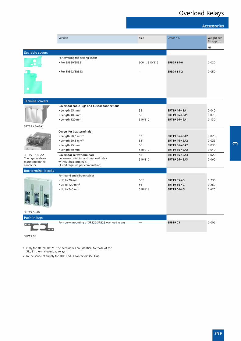
3
3/39
Accessories
Overload Relays
Version Size Order No. Weight perPU approx.
kg
Sealable covers
For covering the setting knobs
• For 3RB20/3RB21 S00 ... S10/S12 3RB29 84-0 0.020
• For 3RB22/3RB23 – 3RB29 84-2 0.050
Terminal covers
Covers for cable lugs and busbar connections
• Length 55 mm1) S3 3RT19 46-4EA1 0.040
• Length 100 mm S6 3RT19 56-4EA1 0.070
• Length 120 mm S10/S12 3RT19 66-4EA1 0.130
3RT19 46-4EA1
Covers for box terminals
• Length 20.6 mm1) S2 3RT19 36-4EA2 0.020
• Length 20.8 mm1) S3 3RT19 46-4EA2 0.025
• Length 25 mm S6 3RT19 56-4EA2 0.030
• Length 30 mm S10/S12 3RT19 66-4EA2 0.040
3RT19 36-4EA2 Covers for screw terminals S6 3RT19 56-4EA3 0.020The figures show between contactor and overload relay, S10/S12 3RT19 66-4EA3 0.060mounting on the without box terminalscontactor (1 unit required per combination)
Box terminal blocks
For round and ribbon cables
• Up to 70 mm2 S62) 3RT19 55-4G 0.230
• Up to 120 mm2 S6 3RT19 56-4G 0.260
• Up to 240 mm2 S10/S12 3RT19 66-4G 0.676
3RT19 5.-4G
Push-in lugs
For screw mounting of 3RB22/3RB23 overload relays — 3RP19 03 0.002
3RP19 03
1) Only for 3RB20/3RB21. The accessories are identical to those of the3RU11 thermal overload relays.
2) In the scope of supply for 3RT10 54-1 contactors (55 kW).

3
3/40
3RU11 for standard applications
Overload Relays
Overview
(1) Connection for mounting onto contactors:Optimally adapted in electrical, mechanical and design terms to thecontactors, these connecting pins can be used for direct mountingof the overload relays. Stand-alone installation is possible as analternative (in some cases in conjunction with a stand-aloneinstallation module).
(2) Selector switch for manual/automatic RESET and RESET button:With this switch you can choose between manual and automaticRESET. A device set to manual RESET can be reset locally by pressingthe RESET button. A remote RESET is possible using the RESETmodules (accessories), which are independent of size.
(3) Switch position indicator and TEST function of the wiring:Indicates a trip and enables the wiring test.
(4) Motor current setting:Setting the device to the rated motor current is easy with the largerotary knob.
(5) STOP button:If the STOP button is pressed, the NC contact is opened. Thisswitches off the contactor downstream. The NC contact is closedagain when the button is released.
(6) Transparent, sealable cover:Secures the motor current setting, TEST function and the selectorswitch for manual/automatic RESET against adjustment.
(7) Supply terminals:The generously sized terminals permit connection of two conductorswith different cross-sections for the main and auxiliary circuits. Theauxiliary circuit can be connected with screw connection andalternatively with spring-type connection.
The 3RU11 thermal overload relays up to 100 A have beendesigned for inverse-time delayed protection of loads withnormal starting against excessive temperature rises due tooverload or phase failure. An overload or phase failure resultsin an increase of the motor current beyond the set rated motorcurrent. Via heating elements, this current rise heats up thebimetal strips inside the device, which then bend and as a reulttrigger the auxiliary contacts by means of a trippingmechanism. The auxiliary contacts then switch off the load bymeans of a contactor. The break time depends on the ratiobetween the tripping current and set current Ie and is stored inthe form of a long-term stable tripping characteristic
The “tripped” status is signaled by means of a switch positionindicator. Resetting takes place either manually orautomatically after a recovery time has elapsed.
The devices are manufactured in accordance withenvironmental guidelines and contain environmentally friendlyand reusable materials.
They comply with all important worldwide standards andapprovals.
“Increased safety” type of protection EEx e according toATEX directive 94/9/EC
The 3RU11 thermal overload relays are suitable for theoverload protection of explosion-proof motors with “increasedsafety” type of protection EEx e. The relays meet therequirements of EN 60079-7 (Electrical apparatus for areassubject to explosion hazards – Increased safety “e”);
EC type test certificate for Category (2) G/D exists. It has thenumber DMT 98 ATEX G 001.
Benefits
The most important features and benefits of the 3RU11thermal overload relays are listed in the overview table
Application
Industries
The 3RU11 thermal overload relays are suitable for customersfrom all industries who want to guarantee optimum inverse-time delayed protection of their electrical loads (e.g. motors)under normal starting conditions (CLASS 10).
Application
The 3RU11 thermal overload relays have been designed for theprotection of three-phase and single-phase AC and DC motors.
If single-phase AC or DC loads are to be protected by the 3RU11thermal overload relays, all three bimetal strips must beheated. For this purpose, all main current paths of the relaymust be connected in series.
Ambient conditions
The 3RU11 thermal overload relays have temperaturecompensation in accordance with IEC 60947-4-1 for thetemperature range of –20 to +60 °C. For temperatures from+60 to +80 °C, the upper set value of the setting range must bereduced by the factor listed in the table below.
Ambient temperature in °C Derating factor for the upperset value
+60 1.0
+65 0.94
+70 0.87
+75 0.81
+80 0.73

3
3/41
3RU11 for standard applications
Overload Relays
Selection and ordering data
3RU11 thermal overload relays with screw terminals on the auxiliary current side for direct mounting1), CLASS 10
Features and technical specifications:• Overload and phase failure protection• Auxiliary contacts 1 NO + 1 NC• Manual and automatic RESET• Switch position indicator
• TEST function• STOP button• Integrated, sealable cover
1) With the suitable terminal brackets (see “Accessories”, page 3/42), the3RU11 overload relays for direct mounting can also be installed as stand-alone units.
2) Observe maximum rated operational current of the devices.
3) Guide value for 4-pole standard motors at 50 Hz 415 V AC. The actualstarting and rated data of the motor to be protected must be consideredwhen selecting the units.
4) Maximum fuse for overload relay, type of coordination 2.
5) For overload relays > 100 A, see 3RB2.
Size of Rating for Set current value Short-circuit protection Screw terminals Weight percontactor2) induction motor of the inverse-time with fuse, type of (on auxiliary current side) PU approx.
Rated value3) delayed overload coordination 2, gL/gGrelease operational class4)
kW A A Order No. kg
Size S00
S00 0.04 0.11 ... 0.16 0.5 3RU11 16-0AB0 0.1500.06 0.14 ... 0.2 1 3RU11 16-0BB0 0.1500.06 0.18 ... 0.25 1 3RU11 16-0CB0 0.1500.09 0.22 ... 0.32 1.6 3RU11 16-0DB0 0.150
0.09 0.28 ... 0.4 2 3RU11 16-0EB0 0.1500.12 0.35 ... 0.5 2 3RU11 16-0FB0 0.1500.18 0.45 ... 0.63 2 3RU11 16-0GB0 0.1500.18 0.55 ... 0.8 4 3RU11 16-0HB0 0.150
0.25 0.7 ... 1 4 3RU11 16-0JB0 0.1503RU11 16 -..B0 0.37 0.9 ... 1.25 4 3RU11 16-0KB0 0.150
0.55 1.1 ... 1.6 6 3RU11 16-1AB0 0.1500.75 1.4 ... 2 6 3RU11 16-1BB0 0.150
0.75 1.8 ... 2.5 10 3RU11 16-1CB0 0.1501.1 2.2 ... 3.2 10 3RU11 16-1DB0 0.1501.5 2.8 ... 4 16 3RU11 16-1EB0 0.1501.5 3.5 ... 5 20 3RU11 16-1FB0 0.150
2.2 4.5 ... 6.3 20 3RU11 16-1GB0 0.1503 5.5 ... 8 25 3RU11 16-1HB0 0.1504 7 ... 10 35 3RU11 16-1JB0 0.1505.5 9 ... 12 35 3RU11 16-1KB0 0.150
Size S0
S0 0.75 1.8 ... 2.5 10 3RU11 26-1CB0 0.1901.1 2.2 ... 3.2 10 3RU11 26-1DB0 0.1901.5 2.8 ... 4 16 3RU11 26-1EB0 0.1901.5 3.5 ... 5 20 3RU11 26-1FB0 0.190
2.2 4.5 ... 6.3 20 3RU11 26-1GB0 0.1903 5.5 ... 8 25 3RU11 26-1HB0 0.1904 7 ... 10 35 3RU11 26-1JB0 0.1905.5 9 ... 12.5 35 3RU11 26-1KB0 0.190
7.5 11 ... 16 40 3RU11 26-4AB0 0.1903RU11 26 -..B0 7.5 14 ... 20 50 3RU11 26-4BB0 0.190
11 17 ... 22 63 3RU11 26-4CB0 0.19011 20 ... 25 63 3RU11 26-4DB0 0.190
Size S2
S2 3 5.5 ... 8 25 3RU11 36-1HB0 0.3204 7 ... 10 35 3RU11 36-1JB0 0.3205.5 9 ... 12.5 35 3RU11 36-1KB0 0.320
7.5 11 ... 16 40 3RU11 36-4AB0 0.3207.5 14 ... 20 50 3RU11 36-4BB0 0.32011 18 ... 25 63 3RU11 36-4DB0 0.32015 22 ... 32 80 3RU11 36-4EB0 0.320
18.5 28 ... 40 80 3RU11 36-4FB0 0.32022 36 ... 45 100 3RU11 36-4GB0 0.320
3RU11 36 -..B0 22 40 ... 50 100 3RU11 36-4HB0 0.320
Size S3
S3 11 18 ... 25 63 3RU11 46-4DB0 0.55015 22 ... 32 80 3RU11 46-4EB0 0.550
18.5 28 ... 40 80 3RU11 46-4FB0 0.55022 36 ... 50 125 3RU11 46-4HB0 0.55030 45 ... 63 125 3RU11 46-4JB0 0.55037 57 ... 75 160 3RU11 46-4KB0 0.550
45 70 ... 90 160 3RU11 46-4LB0 0.5503RU11 46 -..B0 45 80 ... 1005) 200 3RU11 46-4MB0 0.550

3
3/42
Accessories
Overload Relays
Overview
The following optional accessories are available for the 3RU11thermal overload relays:
• For the four overload relay sizes S00 to S3 one terminalbracket each for stand-alone installation
• One electrical remote RESET module in three voltage variantsfor all sizes
• One mechanical RESET module for all sizes
• One cable release for resetting devices which are difficult toaccess (for all sizes)
• Terminal covers
Selection and ordering data
Version Size Order No. Weight perPU approx.
kg
Terminal brackets for stand-alone installation
For separate mounting of overload relays; screw and S00 3RU19 16-3AA01 0.060snap-on mounting onto TH 35 standard mounting rail; S0 3RU19 26-3AA01 0.080size S3 also for TH 75 standard mounting rail
S2 3RU19 36-3AA01 0.180
S3 3RU19 46-3AA01 0.280
3RU19 .6-3AA01
Mechanical RESET1)
Resetting plungers, holders and formers S00 ...S3 3RU19 00-1A 0.038
Pushbuttons with extended stroke 3SB30 00-0EA11 0.020(12 mm), IP65, Ø 22 mm
Extension plungers 3SX1 335 0.004For compensation of the distance between a pushbuttonand the unlatching button of the relay
3RU19 00-1Awith pushbutton andextension plunger
Cable releases with holder for RESET1)
For Ø 6.5 mm holes in the control panel; S00 ...S3max. control panel thickness 8 mm
• Length 400 mm 3RU19 00-1B 0.063
• Length 600 mm 3RU19 00-1C 0.073
3RU19 00-1.
Modules for remote RESET, electrical
Operating range 24 ... 30 V AC/DC S00 ...S3 3RU19 00-2AB71 0.0660.85 ... 1.1 x Us, 110 ... 127 V AC/DC 3RU19 00-2AF71 0.067power consumption
220 ... 250 V AC/DC 3RU19 00-2AM71 0.066AC 80 VA, DC 70 W,ON period 0.2 ... 4 s,switching frequency 60/h
3RU19 00-2A.71
Terminal covers1)
Covers for cable lugs and busbar connections
• Length 55 mm S3 3RT19 46-4EA1 0.040
Covers for box terminals
• Length 20.6 mm S2 3RT19 36-4EA2 0.020
• Length 20.8 mm S3 3RT19 46-4EA2 0.025
1) The accessories are identical to those of the 3RB2 solid-state overloadrelays.

3aProtectionEquipment
3a/2 Introduction
3RV Circuit Breakers/Motor Starter Protectors up to 100 A
General data3a/2 - Design3a/2 - Function3a/2 - Configuration3a/5 - Technical specifications3a/12 - Characteristic curves3a/13 - Dimensional drawings3a/16 - Schematics
Accessories3a/17 Mountable accessories3a/20 Rotary operating mechanisms3a/21 Project planning aids
Overload Relays
3RB2 Solid-State Overload Relays3RB20, 3RB21 for standard applications
3a/25 - Design3a/26 - Function3a/27 - Technical specifications3a/32 - Characteristic curves3a/33 - Dimensional drawings3a/34 - Schematics
3RB22, 3RB23 for high-featureapplica-tions
3a/35 - Design3a/36 - Function3a/38 - Technical specifications3a/43 - Characteristic curves3a/44 - Dimensional drawings3a/46 - Schematics3a/48 Accessories
3RU1 Thermal Overload Relays3RU11 for standard applications
3a/49 - Design3a/50 - Function3a/51 - Technical specifications3a/56 - Characteristic curves3a/57 - Dimensional drawings3a/57 - Schematics3a/58 Accessories

3a
3a/2
General data
Design
Screw terminals
3RV1 motor starter protectors of sizes S00 and S0 are fittedwith terminals with captive screws and clamping pieces,allowing the connection of 2 conductors with different cross-sections.
The box terminals of the S2 and S3 motor starter protectorsalso enable 2 conductors with different cross-sections to beconnected. With the exception of S3 motor starter protectorswhich are equipped with 4 mm Allen screws, all terminalscrews are tightened with a Pozidriv screwdriver size 2.
The box terminals of the S3 motor starter protectors can beremoved in order to connect conductors with cable lugs orconnecting bars. A terminal cover is available as touchprotection and to ensure that the required clearances andcreepage distances are maintained if the box terminals areremoved.
Mounting
The motor starter protectors are snap-fitted on a 35 mmstandard mounting rail to EN 60715.
����������
�
���
���
��
Push-in lugs for screwing the motor starter protector onto mountingplates.
A standard mounting rail with a height of 15 mm is requiredfor size S3 motor starter protectors. A 75 mm standardmounting rail can be used as an alternative for size S3.
S2 and S3 motor starter protectors can also be screwed directlyonto a base plate.
The 3RB19 00-0B push-in lugs are available for screw mountingof S00 and S0 motor starter protectors.
Function
Trip units
3RV1 motor starter protectors are equipped with inverse-timedelayed overload release based on the bimetal principle andwith instantaneous electronic trip units (electromagnetic short-circuit releases).
The overload releases can be adjusted in accordance with theload current. The electronic trip units are permanently set to avalue 13 times the rated current and thus enable trouble-freestarting of motors.
Motor starter protectors for line-side transformer protection areset to 20 times the rated current to prevent tripping as a resultof high transformer inrush current.
The scale cover can be sealed to prevent unauthorizedadjustments to the set current.
Trip classes
The trip classes of thermally delayed trip units are based on thetripping time (tA) at 7.2 times the set current in cold state(excerpt from IEC 60947-4):
• CLASS 10A: 2 s < tA < 10 s
• CLASS 10: 4 s < tA < 10 s
• CLASS 20: 6 s < tA < 20 s
• CLASS 30: 9 s < tA < 30 s
The motor starter protector must trip within this time!
Operating mechanisms
S00 motor starter protectors are actuated by a rocker operatingmechanism and S0, S2 and S3 motor starter protectors by arotary operating mechanism. If the motor starter protectortrips, the rotary operating mechanism switches to the trippedposition to indicate this. Before the motor starter protector isreclosed, the rotary operating mechanism must be resetmanually to the 0 position. Only then can the motor starterprotector be set again to the I position.
In the case of motor starter protectors with rotary operatingmechanisms, an electrical signal can be output by a signalingswitch to indicate that the motor starter protector has tripped.
All operating mechanisms can be locked in the 0 position witha padlock (shackle diameter 3.5 mm to 4.5 mm).
The motor starter protector isolating function complies withIEC 60947-2.
Configuration
Prevention of unintended tripping
In order to prevent premature tripping due to the integratedphase failure sensitivity, motor starter protectors should alwaysbe connected to ensure current flows through all three maincurrent paths.
Short-circuit protection
If a short-circuit occurs, the short-circuit releases of 3RV1motor starter protectors isolate the faulty load feeder from thenetwork and thus prevent further damage.
Motor starter protectors with a short-circuit breaking capacityof 50 kA or 100 kA are virtually short-circuit resistant at avoltage of 400 V AC, since higher short-circuit currents are notto be expected in practice.
Motor protection
The tripping characteristics of 3RV10/3RV11 motor starterprotectors are designed mainly to protect induction motors.
The motor starter protectors are therefore also referred to asmotor circuit breakers.
The rated current In of the motor to be protected is set on thesetting scale. Factory setting of the short-circuit release is 13times the rated current of the motor starter protector. Thispermits trouble-free starting and ensures that the motor isproperly protected.
The phase failure sensitivity of the motor starter protectorensures that it is tripped in time in the event of a phase failureand overcurrents that occur as a result in the other phases.
Motor starter protectors with thermal overload releases arenormally designed in accordance with trip class 10 (CLASS 10).Motor starter protectors of sizes S2 and S3 are also available in
3RV Circuit Breakers/Motor Starter Protectors up to 100 A

3a
3a/3
General data
trip class 20 (CLASS 20) and therefore allow motors to bestarted up under arduous conditions.
Motor protection with overload relay function(automatic RESET)
The 3RV11 motor starter protectors for motor protection withoverload relay function are designed for the protection ofinduction motors.
They are equipped with the same short-circuit release andoverload release as motor starter protectors for motorprotection without overload relay function.
The motor starter protector always remains closed in the eventof an overload. The overload release activates only twoauxiliary contacts (1 NO + 1 NC). The overload trip can besignaled to a higher-level control with the help of theseauxiliary contacts. Generally, it is also possible to open adownstream contactor directly.
The overload signal is reset automatically. The motor starterprotector itself only trips if a short-circuit occurs downstream.
System protection
The 3RV10 and 3RV11 motor starter protectors for motorprotection are also suitable for plant protection.
In order to prevent premature tripping due to phase failuresensitivity, the three conducting paths must always beuniformly loaded. The conducting paths must be connected inseries in the case of single-phase loads.
The 3RV17 and 3RV18 circuit breakers are suitable for systemprotection and at the same time they are approved as circuitbreakers according to UL 489 and CSA C22.2 No. 5-02.
Short-circuit protection for starter combinations
The 3RV13 motor starter protectors for starter combinations insizes S0, S2 and S3 provide short-circuit protection with thehelp of a contactor and overload relay combination.
Like the motor starter protectors for motor protection, they areequipped with short-circuit releases which are permanently setto a value equivalent to 13 times the rated current of the motorstarter protectors. They are not equipped with overloadreleases.
On overload, the overload relay triggers the contactor, themotor starter protector remains closed.
Only when a short-circuit occurs in the feeder does the motorstarter protector trip as well.
The motor starter protector for starter combinations mustalways be used in combination with an overload relay becausethe motor starter protector alone cannot protect the motor anditself against overload.
Transformer protection
When control transformers are protected on the line side, thehigh inrush currents generated at the time the transformersare switched on often cause spurious tripping in the protectionmechanisms.
3RV14 motor starter protectors in sizes S0 and S2 and 3RV18circuit breakers in size S0 for protecting transformers aretherefore fitted with electronic trip units which arepermanently set in the factory to a value equivalent to 20times the rated current. For the 3RV17 circuit breakers in sizesS0 and S3 these electronic trip units are set in the factory toapproximately 13 times the rated current.
Motor starter protectors can thus be used to provide line-sideprotection for transformers, the inrush peak currents of whichare up to 30 times the rated current.
The 3RV17 and 3RV18 are approved as circuit breakersaccording to UL 489 and CSA 22.2 No. 5-02 for the protectionof transformers, the 3RV18 circuit breakers size S0 aredesigned specially for the protection of transformers with highinrush current.
This version of motor starter protector is not necessary in thecase of control-power transformers with low inrush currents,such as control transformers from Siemens. 3RV1 motor starterprotectors for motor protection can be used in this case.
Main and EMERGENCY-STOP switches
The 3RV10, 3RV11, 3RV13, 3RV14 and 3RV16 motor starterprotectors comply with the isolating function to IEC 60947-2,therefore they can be used – taking IEC 60204-1 into account –as main and EMERGENCY-STOP switches.
3RV19 .6-2. door-coupling rotary operating mechanisms forheavy duty also comply with the requirements for the isolatingfunction.
Fuse monitoring
The 3RV16 11-0BD10 motor starter protector size S00 is usedfor fuse monitoring.
A fuse is connected in parallel with each conducting path ofthe motor starter protector. When a fuse blows, the currentflows through the parallel conducting path and trips the motorstarter protector.
The 3RV16 11-0BD10 motor starter protector must beequipped with a transverse or lateral auxiliary switch (see“Accessories”) that signals a tripping operation of the motorstarter protector and thus the tripping of the fuse, or switchesoff all poles of the disrupted electric circuit with the help of anappropriate switching device.
Motor starter protector for fuse monitoring
Notes on safety
When monitoring fuses with safety isolating functions, awarning sign must be affixed near the fuses indicating thatvoltage may still be present through the parallel circuit of themonitoring equipment assumed to be isolated after the fusehas been removed and if the monitoring equipment is notswitched off.
We recommend the following text for this warning:
Important!For safety isolation, also switch off fuse monitoring equipmentwith the item code ......
3RV Circuit Breakers/Motor Starter Protectors up to 100 A

3a
3a/4
The 3RV16 11-0BD10 motor starter protector for fusemonitoring is suitable for the following voltages: AC 50 Hz/60 Hz from 24 V to 690 V and up to 450 V DC. Fuse monitoringwith 3RV16 11-0BD10 motor starter protector is notpermissible in feeders with power control regulators that caninduce DC feedback of higher values when an error occurs.
With parallel cables and meshed systems, the motor starterprotector will only trip, and a signal will be output to indicatethis, if the voltage difference across the motor starter protectoris at least 24 V.
Use of IT systems (IT networks)
3RV1 motor starter protectors are suitable for operation inIT systems according to IEC 60947-2. In the event of a 3-poleshort-circuit, their response in this system is the same as inothers: Therefore, the same short-circuit breaking capacity Icu
and Ics applies, see “Technical specifications”.
An initial fault (ground fault) does not necessarily forceimmediate disconnection of the network when operatingIT systems. If a second independent error occurs (ground fault),the switching capacity of the motor starter protector might bereduced.
This is the case if both ground faults occur in different phasesand if one of the ground faults occurs on the input side and theother on the outgoing terminal of the motor starter protector.
In order to maintain the short-circuit function of the motorstarter protector even with two independent ground faults(double ground faults), the reduced short-circuit breakingcapacity with double ground faults must be taken into accountin IT systems IcuIT (see “Technical specifications”). If a groundfault is instantaneously recognized and remedied (ground-faultmonitoring), the risk of double ground fault and thus reducedshort-circuit breaking capacity IcuIT can be minimized.
Switching of DC currents
3RV1 motor starter protectors for alternating currents are alsosuitable for DC switching.
The maximum permissible DC voltage per conducting pathmust, however, be adhered to. Higher voltages require a seriesconnection with 2 or 3 conducting paths.
The response values of the overload release remainunchanged; the response values of a short-circuit releaseincrease by approximately 30 % for DC. The example circuits forDC switching can be seen in the table below.
1) It is assumed that this circuit always provides safe disconnection even inthe event of a double ground fault that bridges two contacts.
NSB0_00001aM
L+ L
NSB0_00002aM
L+ L
NSB0_00003aM
L+ L
Example circuit for size S00 to S3 3RV1 motor starter protectors
Example circuit for Maximum permitted Notessize S00 to S3 3RV1 DC voltage Ue
motor starter protectors
150 V DC 2-pole switching, non-grounded system1)
If there is no possibility of a ground fault, or if every ground fault is rectified immediately(ground-fault monitoring), then the maximum permitted DC voltage can be tripled.
300 V DC 2-pole switching, grounded systemThe grounded pole is always assigned to the individual conducting path, so that thereare always 2 conducting paths in series in the event of a ground fault.
450 V DC 1-pole switching, grounded system3 conducting paths in series. The grounded pole is assigned to the unconnectedconducting path.
General data
3RV Circuit Breakers/Motor Starter Protectors up to 100 A

3a
3a/5
Technical specifications
Short-circuit breaking capacity Icu, Ics according toIEC 60947-2
This table shows the rated ultimate short-circuit breaking
capacity Icu and the rated service short-circuit breaking capacityIcs of the 3RV1 motor starter protectors with different inceptionvoltages dependent of the rated current In of the motor starterprotectors.
Motor starter protector infeed is permissible at the upper orlower terminals without restricting the rated data. If the short-circuit current at the place of installation exceeds the ratedshort-circuit breaking capacity of the motor starter protector as
specified in the table, a back-up fuse is required. Alternatively,a motor starter protector with a limiter function can beconnected upstream.
The maximum rated current for the back-up fuse is specified inthe tables. The rated ultimate short-circuit breaking capacitythen applies as specified on the fuse.
Fuseless construction
Motor starter protector contactor combinations for short-circuitcurrents up to 50 kA can be ordered in the form of fuselessload feeders according to Part 6.
1) 10 % overvoltage.2) 5 % overvoltage.3) Back-up fuse only required if the short-circuit current at the place of
installation > Icu.
4) Alternatively, fuseless limiter combinations for 690 V AC can also beused.
5) The values for the 3RV17 42 circuit breakers have been tested only up to400 V/415 V AC; values > 440 V AC on request.
Circuit breakers/ Rated Up to AC 240 V1) Up to AC 400 V1)/415 V2) Up to AC 440 V1)/460 V2) Up to AC 500 V1)/525 V2) Up to AC 690 V1)
Motor starter current In
protectors (these values do not apply 3RV17 42 circuit breakers)
Icu Ics max. fuse Icu Ics Max. fuse Icu Ics Max. Icu Ics Max. fuse Icu Ics Max. fuse(gL/gG) (gL/gG)3) fuse (gL/gG)3) (gL/gG)3) (gL/gG)3)4)
Type A kA kA A kA kA A kA kA A kA kA A kA kA A
Size S003RV10, 0.16 ... 1 100 100 ° 100 100 ° 100 100 ° 100 100 ° 100 100 °3RV16 11-0BD10 1.25; 1.6 100 100 ° 100 100 ° 100 100 ° 100 100 ° 2 2 20
2; 2.5 100 100 ° 100 100 ° 100 100 ° 10 10 35 2 2 35
3.2; 4 100 100 ° 100 100 ° 50 10 40 3 3 40 2 2 40 5; 6.3 100 100 ° 100 100 ° 50 10 50 3 3 50 2 2 50 8 100 100 ° 50 12.5 80 50 10 63 3 3 63 2 2 63
10 100 100 ° 50 12.5 80 10 10 63 3 3 63 2 2 63 12 100 100 ° 50 12.5 80 10 10 80 3 3 80 2 2 80
Size S03RV1. 2, 0.16 ... 1.6 100 100 ° 100 100 ° 100 100 ° 100 100 ° 100 100 °3RV17 21, 2; 2.5 100 100 ° 100 100 ° 100 100 ° 100 100 ° 8 8 253RV18 21 3.2 100 100 ° 100 100 ° 100 100 ° 100 100 ° 8 8 32 4; 5 100 100 ° 100 100 ° 100 100 ° 100 100 ° 6 3 32 6.3 100 100 ° 100 100 ° 100 100 ° 100 100 ° 6 3 50
8 100 100 ° 100 100 ° 50 25 63 42 21 63 6 3 50 10 100 100 ° 100 100 ° 50 25 80 42 21 63 6 3 50 12.5 100 100 ° 100 100 ° 50 25 80 42 21 80 6 3 63 16 100 100 ° 50 25 100 50 10 80 10 5 80 4 2 63
20 100 100 ° 50 25 125 50 10 80 10 5 80 4 2 63 22; 25 100 100 ° 50 25 125 50 10 100 10 5 80 4 2 63
Size S23RV1. 3 16 100 100 ° 50 25 100 50 25 100 12 6 63 5 3 63
20 100 100 ° 50 25 100 50 25 100 12 6 80 5 3 63 25 100 100 ° 50 25 100 50 15 100 12 6 80 5 3 63 32 100 100 ° 50 25 125 50 15 125 10 5 100 4 2 63
40; 45 100 100 ° 50 25 160 50 15 125 10 5 100 4 2 63 50 100 100 ° 50 25 160 50 15 125 10 5 100 4 2 80
Size S33RV1. 41 40 100 100 ° 50 25 125 50 20 125 12 6 100 6 3 63
50 100 100 ° 50 25 125 50 20 125 12 6 100 6 3 8063 100 100 ° 50 25 160 50 20 160 12 6 100 6 3 80
75 100 100 ° 50 25 160 50 20 160 8 4 125 5 3 100 90; 100 100 100 ° 50 25 160 50 20 160 8 4 125 5 3 125
Size S3, with increasedswitching capacity3RV1. 42 / 16 / 10 100 100 ° 100 50 ° 100 50 ° 30 15 80 12 7 633RV17 425) 20 / 15 100 100 ° 100 50 ° 100 50 ° 30 15 80 12 7 63
25 / 20 100 100 ° 100 50 ° 100 50 ° 30 15 80 12 7 6332 / 25 100 100 ° 100 50 ° 100 50 ° 22 11 100 12 7 63
40 / 30 100 100 ° 100 50 ° 100 50 ° 18 9 160 12 6 80 50 / 35 ... 40 100 100 ° 100 50 ° 100 50 ° 15 7.5 160 10 5 100 63 / 45 ... 50 100 100 ° 100 50 ° 70 50 200 15 7.5 160 7.5 4 100
75 / 60 100 100 ° 100 50 ° 70 50 200 10 5 160 6 3 125 90 / 70 100 100 ° 100 50 ° 70 50 200 10 5 160 6 3 160 100 / — 100 100 ° 100 50 ° 70 50 200 10 5 160 6 3 160
Short-circuit resistant up to at least 50 kA
° No back-up fuse required, since short-circuit resistant up to 100 kA
General data
3RV Circuit Breakers/Motor Starter Protectors up to 100 A

3a
3a/6
Limiter function with standard devices for 500 V AC and690 V AC according to IEC 60947-2
The table shows the rated ultimate short-circuit breakingcapacity Icu and the rated service short-circuit breaking capacityIcs with an upstream standard motor starter protector thatfulfills the limiter function at 500 V AC and 690 V AC. Theshort-circuit breaking capacity can be increased significantlywith an upstream standard motor starter protector.
The motor starter protector which is connected downstreammust be set to the rated current of the load.
With motor starter protector combination assemblies, note theclearance to grounded parts and between the motor starterprotectors. Short-circuit resistant wiring between the motorstarter protectors must be ensured. The motor starterprotectors can be mounted side-by-side in a modulararrangement.
Standard Standard Rated current In Up to AC 500 V1)/525 V2) Up to AC 690 V1)
motor starter motor starter Icu Ics Icu Ics
protectors protectors withlimiter functionType
Type Rated current In A kA kA kA kA
Size S0
3RV10 2 3RV13 21-4DC10 up to 1 ° ° ° °1.25 ° ° ° °
In = 25 A 1.6 ° ° ° ° 2 ° ° 50 25
2.5 ° ° 50 25 3.2 ° ° 50 25 4 ° ° 50 25 5 ° ° 50 25
6.3 ° ° 50 25 8 100 50 20 10 10 100 50 20 10 12.5 100 50 20 10
16 100 50 20 10 20 100 50 20 10 22 100 50 20 10 25 100 50 20 10
Size S2
3RV10 3 3RV13 31-4HC10 16 100 50 50 2520 100 50 50 25
In = 50 A 25 100 50 50 25
32 100 50 50 25 40 100 50 50 25 50 100 50 50 25
Size S3
3RV10 4 3RV13 41-4HC10 32 100 50 50 2540 100 50 50 25
In = 50 A 50 100 50 50 25
3RV13 41-4MC10 50 100 50 50 2563 100 50 50 25
In = 100 A 75 100 50 50 25
90 100 50 50 25 100 100 50 50 25
Short-circuit resistant up to 100 kA
° No back-up fuse required, since short-circuit resistant up to 100 kA
1) 10 % overvoltage.
2) 5 % overvoltage.
General data
3RV Circuit Breakers/Motor Starter Protectors up to 100 A

3a
3a/7
General technical specifications
Type 3RV1. 11) 3RV1. 2 3RV1. 3 3RV1. 4 3RV17 21 3RV17 42
Standards• IEC 60947-1, EN 60947-1 (VDE 0660 Part 100) Yes• IEC 60947-2, EN 60947-2 (VDE 0660 Part 101) Yes• IEC 60947-4-1, EN 60947-4-1 (VDE 0660 Part 102) Yes No• UL 489, CSA C22.2-No.5-02 No Yes
Size S00 S0 S2 S3 S0 S3
Number of poles 3
Max. rated current In max A 12 25 50 100 22 70(= max. rated operational current Ie)
Permissible ambient temperature• Storage/transport °C –50 ... +80• Operation °C –20 ... +702)
Permissible rated current at inside temperature of control cabinet • +60 °C % 100• +70 °C % 87
Motor starter protector/circuit breaker inside enclosurePermissible rated current at ambient temperature of enclosure • +35 °C % 100• +60 °C % 87
Rated operational voltage Ue
• Acc. to IEC V AC 6903)
• Acc. to UL/CSA V AC 600
Rated frequency Hz 50/60
Rated insulation voltage Ui V 690
Rated impulse withstand voltage Uimp kV 6
Utilization categories• IEC 60947-2 (motor starter protector/circuit breaker) A• IEC 60947-4-1 (motor starter) AC-3 —
Trip class CLASS Acc. to IEC 60947-4-1 10 10/20 —
DC short-circuit breaking capacity (time constant t = 5 ms) • 1 conducting path 150 V DC kA 10• 2 conducting paths in series 300 V DC kA 10• 3 conducting paths in series 450 V DC kA 10
Power loss Pv per motor starter In: ... 1.25 A W 5 —protector/circuit breaker In: 1.6 ... 6.3 A W 6 —Dependent on rated current In In: 8 ... 12 A W 7 —(upper setting range) In: ... 0.63 A W — 5 — 5 —Rper conducting path = P/I2 x 3 In: 0.8 ... 6.3 A W — 6 — 6 —
In: 8 ... 16 A W — 7 — 7 —In: 20 ... 25 A W — 8 — 8 —
In: ... 25 A W — 12 —In: 32 A W — 15 —In: 40 ... 50 A W — 20 —
In: ... 63 A W — 20 —In: 75 and 90 A W — 30 —In: ... 100 A W — 38 —
In: ... 10 A W — 8In: ... 35 A W — 12In: ... 70 A W — 21
Shock resistance Acc. to IEC 60068-2-27 g/ms 25/11 (square and sine pulse)
Degree of protection Acc. to IEC 60529 IP204)
Touch protection Acc. to EN 50274 Finger-safe
Temperature compensation Acc. to IEC 60947-4-1 °C –20 ... +60
Phase failure sensitivity Acc. to IEC 60947-4-1 Yes No
Explosion protection – Safe operation of motors with Yes, for 3RV10 (CLASS 10) No“increased safety” type of protection
EC type test certificate number acc. to directive 94/9/EC (ATEX) DMT 02 ATEX F 001 II (2) GD,DMT 02 ATEX F 001 N1 II (2) GD
Isolating function Acc. to IEC 60947-2 YesMain and EMERGENCY-STOP switch Acc. to IEC 60204-1 Yescharacteristics5) (VDE 0113)
Safe isolation between main and Acc. to EN 60947-1auxiliary circuits, req. for PELV applications • Up to 400 V + 10 % Yes• Up to 415 V + 5 % (higher voltages on request) Yes
Permissible mounting positions Any, acc. to IEC 60447 start command “I” right-hand side or top
Mechanical endurance Operating cycles 100000 50000 100000 50000
Electrical endurance Operating cycles 100000 25000 100000 25000
Max. switching frequency per hour (motor starts) 1/h 15
For footnotes see page 3a/8
For short-circuit breaking capacity Icu, Ics see table of same name.
General data
3RV Circuit Breakers/Motor Starter Protectors up to 100 A

3a
3a/8
Footnotes for page 3a/7:
1) For 3RV16 voltage transformer circuit breakers see more “Technicalspecifications”.
2) Above +60 °C current reduction.
3) 500 V with molded-plastic enclosure.
4) Terminal compartment IP00.
5) With appropriate accessories.
1) Cable-lug and busbar connection possible after removing the boxterminals.
2) If bars larger than 12 mm x 10 mm are connected, a 3RT19 46-4EA1terminal cover is needed to comply with the phase clearance.
3) If conductors larger than 25 mm2 are connected, a 3RT19 46-4EA1terminal cover is needed to comply with the phase clearance.
4) If two different conductor cross-sections are connected to one clampingpoint, both cross-sections must lie in the range specified. If identicalcross-sections are used, this restriction does not apply.
Conductor cross-sections of main circuit
Type 3RV1. 3RV1. 2 3RV1. 3 3RV1. 4/ 3RV17 213RV17 42
Connection type Screw terminals Screw terminalswith box terminals
Terminal screw Pozidriv size 2 Pozidriv size 2 4 mm Allen screw Pozidriv size 2
Prescribed tightening torque Nm 0.8 ... 1.2 2 ... 2.5 3 ... 4.5 4 ... 6 2.5 ... 3
Conductor cross-sections(1 or 2 conductors connectable)
• Solid mm2 2 x (0.5 ... 1.5)4), 2 x (1 ... 2.5)4), 2 x (0.75 ... 16) 2 x (2.5 ... 16) 1 ... 10,2 x (0.75 ... 2.5)4) 2 x (2.5 ... 6)4) max. 2 x 10
• Finely stranded with end sleeve mm2 2 x (0.5 ... 1.5)4), 2 x (1 ... 2.5)4), 2 x (0.75 ... 16), 2 x (2.5 ... 35), 1 ... 16,2 x (0.75 ... 2.5)4) 2 x (2.5 ... 6)4) 1 x (0.75 ... 25) 1 x (2.5 ... 50) max. 6 + 16
• Stranded mm2 2 x (0.5 ... 1.5)4), 2 x (1 ... 2.5)4), 2 x (0.75 ... 25), 2 x (10 ... 50), 1.5 ... 25,2 x (0.75 ... 2.5)4) 2 x (2.5 ... 6)4) 1 x (0.75 ... 35) 1 x (10 ... 70) max. 10 + 25
• AWG cables, solid or stranded AWG 2 x (18 ... 14) 2 x (14 ... 10) 2 x (18 ... 2), 2 x (10 ... 1/0), 2 x (14 ... 10)1 x (18 ... 2) 1 x (10 ... 2/0)
Ribbon cable conductors mm — 2 x (6 x 9 x 0.8) —(number x width x thickness)
Removable box terminals1)
• With copper bars2) — — 18 x 10 —
• With cable lugs3) — — up to 2 x 70 —
General data
3RV Circuit Breakers/Motor Starter Protectors up to 100 A

3a
3a/9
Motor starter protectors of the 3RV1 series are approved for UL/CSA and according to UL 508 and CSA C22.2 No. 14 they canbe used on their own or as a load feeder in combination with acontactor.
Permissible rated data of devices approved for North America (UL/CSA)
These motor starter protectors can be used as “Manual MotorControllers” for “Group Installations”, as “Manual MotorControllers Suitable for Tap Conductor Protection in GroupInstallations” and as “Self-Protected Combination MotorControllers” (Type E).
3RV1 motor starter protectors as “Manual Motor Controllers”
If used as a “Manual Motor Controller”, the motor starterprotector is always operated in combination with an upstreamshort-circuit protection device. Approved fuses or a circuitbreaker according to UL 489/CSA C22.2 No. 5-02 can be used.These devices must be dimensioned according to the NationalElectrical Code (UL) or Canadian Electrical Code (CSA).
Approval of the 3RV as a Manual Motor Controller can be foundunder the following file numbers:
• UL File No. 47705, CCN: NLRV,
• CSA Master Contract 165071, Product Class: 3211 05.
Motor starter protectors hp rating1) for FLA2) Rated current 240 V AC 480 V AC 600 V ACmax. In UL CSA UL CSA UL CSA
Ibc3) Ibc
3) Ibc3) Ibc
3) Ibc3) Ibc
3)
Type V 1-phase 3-phase A kA kA kA kA kA kA
Size S00
3RV10 11, 3RV16 11-0BD10 0.16 ... 2 65 65 65 65 10 10 2.5 65 65 65 65 10 10
FLA2) max. 12 A, 115 1/2 — 3.2 65 65 65 65 10 10600 V 200 1 1/2 3
4 65 65 65 65 10 10NEMA size 00 230 2 3 5 65 65 65 65 10 10
460 — 7 1/2 6.3 65 65 65 65 10 10575/600 — 10 8 65 65 65 65 10 10
10 65 65 65 65 10 10 12 65 65 65 65 10 10
Size S0
3RV10 21 / 3RV11 21, 3RV13 21 0.16 ... 3.2 65 65 65 65 30 30 4 65 65 65 65 30 30FLA2) max. 25 A, 115 2 — 5 65 65 65 65 30 30600 V 200 3 5
6.3 65 65 65 65 30 30NEMA size 1 230 3 7 1/2 8 65 65 65 65 30 30
460 — 15 10 65 65 65 65 30 30575/600 — 20
12.5 65 65 65 65 30 3016 65 65 65 65 10 10
20 65 65 65 65 10 10
22 65 65 65 65 10 10 25 65 65 65 65 10 10
Size S2
3RV10 31 / 3RV11 31, 3RV13 31 16 65 65 65 65 30 25 20 65 65 65 65 30 25FLA2) max. 50 A, 115 3 — 25 65 65 65 65 30 25600 V 200 7 1/2 15
32 65 65 65 65 30 25NEMA size 2 230 10 20 40 65 65 65 65 30 25
460 — 40 45 65 65 65 65 30 25575/600 — 50 50 65 65 65 65 30 25
Size S3
3RV10 41 / 3RV10 42, 3RV11 42, 3RV13 41 / 3RV13 42 16 65 65 65 65 30 30 20 65 65 65 65 30 30FLA2) max. 99 A, 115 7 1/2 — 25 65 65 65 65 30 30600 V 200 20 30
32 65 65 65 65 30 30NEMA size 3 230 20 40 40 65 65 65 65 30 30
460 — 75 50 65 65 65 65 30 30575/600 — 100
63 65 65 65 65 30 30 75 65 65 65 65 30 30 90 65 65 65 65 10 10
100 65 65 65 65 10 10
1) hp rating = Power rating in horse power (maximum motor rating).
2) FLA = Full Load Amps/Motor full load current.
3) Complies with “short-circuit breaking capacity” according to UL/CSA.
General data
3RV Circuit Breakers/Motor Starter Protectors up to 100 A

3a
3a/10
These circuit breakers are approved according to UL 489 andCSA C22.2 No. 5-02. They can be used therefore as upstreamshort-circuit protective devices for “Manual Motor Controllers”and “Manual Motor Controllers Suitable for Tap ConductorProtection in Group Installations”.
3RV17 circuit breakers
The 3RV17 circuit breakers are approved under the followingfile numbers:
• UL File No. E235044, CCN: DIVQ,
• CSA Master Contract 165071, Product Class: 1432 01.
Circuit breakers Rated current In 240 V AC 480 Y/277 V AC 600 Y/347 V ACUL CSA UL CSA UL CSA
Ibc1) Ibc
1) Ibc1) Ibc
1) Ibc1) Ibc
1)
Type A kA kA kA kA kA kA
Size S0
3RV17 21 0.16 50 50 50 50 10 100.2 50 50 50 50 10 100.25 50 50 50 50 10 100.32 50 50 50 50 10 10
0.4 50 50 50 50 10 100.5 50 50 50 50 10 100.63 50 50 50 50 10 100.8 50 50 50 50 10 10
1 50 50 50 50 10 101.25 50 50 50 50 10 101.6 50 50 50 50 10 102 50 50 50 50 10 10
2.5 50 50 50 50 10 103.2 50 50 50 50 10 104 50 50 50 50 10 105 50 50 50 50 10 10
6.3 50 50 50 50 10 108 50 50 50 50 10 1010 50 50 50 50 — —12.5 50 50 50 50 — —
15 50 50 50 50 — —20 50 50 50 50 — —22 50 50 50 50 — —
Size S3
3RV17 42 10 65 65 65 65 20 20 15 65 65 65 65 20 20
20 65 65 65 65 20 20 25 65 65 65 65 20 20
30 65 65 65 65 20 2035 65 65 65 65 20 2040 65 65 65 65 20 20
45 65 65 65 65 20 20
50 65 65 65 65 20 20 60 65 65 65 65 20 20 70 65 65 65 65 20 20
1) Complies with “short-circuit breaking capacity” according to UL.
General data
3RV Circuit Breakers/Motor Starter Protectors up to 100 A

3a
3a/11
Rated data of the auxiliary switches and signaling switches
Type Lateral auxiliary Transverse auxiliary switches withswitches with1 NO + 1 NC, 2 NO, 1 CO contact 1 NO + 1 NC, 2 NO2 NC,2 NO + 2 NCand signaling switch
Max. rated voltage Acc. to NEMA (UL) V AC 600 250Acc. to NEMA (CSA) V AC 600 250
Uninterrupted current A 10 5 2.5Switching capacity A600 B600 C300
Q300 R300 R300
Conductor cross-sections, main circuit, 1 or 2 conductors
Type 3RV16 11-1AG14 3RV16 11-1CG14 3RV16 11-1DG14
Connection type Screw terminals
Terminal screw Pozidriv size 2
Conductor cross-sections
• Solid mm2 2 x (0.5 ... 1.5)1), 2 x (0.75 ... 2.5)1), max. 4
• Finely stranded with end sleeve mm2 2 x (0.5 ... 1.5)1), 2 x (0.75 ... 2.5)1)
• Stranded mm2 2 x (0.5 ... 1.5)1), 2 x (0.75 ... 2.5)1), max. 4
Auxiliary switch for blocking the distance protection
• With defined lateral assignment for blocking distance protection 1 changeover contact (for use as 1 NO or 1 NC)
• Rated operational voltage Ue (AC voltage) V 25
• Rated operational current Ie /AC-14 at Ue = 250 V A 0.5
• Rated operational current Ie /AC-14 at Ue = 125 V A 1
• Rated operational voltage Ue (DC voltage L/R 200 ms) V 250
• Rated operational current Ie /DC-13 at Ue = 250 V A 0.27
• Rated operational current Ie /DC-13 at Ue = 125 V A 0.44
Short-circuit protection for auxiliary circuit
• Melting fuse gL/gG A 10
• Miniature circuit breaker, C characteristic A 6 (prospective short-circuit current < 0.4 kA)
Auxiliary switches for other signaling purposes
For technical specifications see “Mountable Accessories”
1) If two different conductor cross-sections are connected to one clampingpoint, both cross-sections must lie in the range specified. If identicalcross-sections are used, this restriction does not apply.
General data
3RV Circuit Breakers/Motor Starter Protectors up to 100 A

3a
3a/12
Characteristic curves
The time/current characteristic, the current limitingcharacteristics and the I2t characteristic curves weredetermined according to DIN VDE 0660 and IEC 60947.
The tripping characteristic of the inverse-time delayed overloadrelease (thermal overload releases, ‘a’ releases) for DC and ACwith a frequency of 0 Hz to 400 Hz applies for the time/currentcharacteristic.
The characteristic curves apply to the cold state; at operatingtemperature, the tripping times of the thermal trip units arereduced to approximately 25 %.
Under normal operating conditions, all three poles of thedevice must be loaded. The three main current paths must beconnected in series in order to protect single-phase or DCloads.
With 2-pole and 3-pole loading, the maximum deviation in thetripping time of 3 times the set current and upwards is ±20 %and thus in accordance with DIN VDE 0165.
The tripping characteristics for the instantaneous,electromagnetic electronic trip units (short-circuit releases, ‘n’releases) are based on the rated current In that also representsthe maximum value of the setting range for motor starterprotectors with adjustable overload releases. If the current isset to a lower value, the tripping current of the ‘n’ release isincreased by a corresponding factor.
The characteristic curves of the electromagnetic electronic tripunits apply to frequencies of 50 Hz/60 Hz. Appropriatecorrection factors must be used for lower frequencies down to16 2/3 Hz, for higher frequencies up to 400 Hz and for DC.
Schematic representation of typical time/current characteristic of 3RV10
The above characteristic curve for the motor starter protectorrelates to a specific setting range. It is, however, also valid as aschematic representation of motor starter protectors with othercurrent ranges.
10
5
2
1
10 000
5000
2000
1000
500
200
100
50
20
10
5
0,2
1
0,5
0,02
0,1
0,05
0,002
0,01
0,005
100
6040
2
0,6 0,81 2 3 4 6 8 10
0,00120 30 40 80 x n
NSB0_00004b
min
60
3-poleloadingClass 20
3-pole loadingClass 10
2-pole loadingClass 10
Opening time
Current
General data
3RV Circuit Breakers/Motor Starter Protectors up to 100 A

3a
3a/13
Dimensional drawings
3RV1 motor starter protectors, size S00
3RV10 11, 3RV 16
3RV1 motor starter protectors, size S0
3RV10 21, 3RV13 21, 3RV14 21
�� ��� �� ����
��
�
��
��
�
���
��
����
� ��
� �
��
�
��
���
��
�
��
�
�
���
��
��� � �� ��
��
����
�
��
��
��
��
��
�
��
��
�� � ��
����
��
���� ��
�
�
�
�
���
��
3RV1 motor starter protectors, size S2
3RV10 31, 3RV13 31, 3RV14 31
20
55189 18
45 85
109
121
1275
8
132144
140
89125
1) 2)
3)4)
8)
NS
B00
028a
11)
5
30
130
7)
3RV1 motor starter protectors, size S3
3RV10 4, 3RV13 4
� �
� �� � � �
� ��
� ��
� ��
�
�
�
� � � � � �
� � �� � �� � �
� � � �
� �
� �
��� �
� ��
� �
� � �
�
�
�
���
� �
1) Lateral auxiliary switch, 2-pole.
2) Signaling switch (S0 ... S3) or lateral auxiliary switch, 4-pole (S00 ... S3).
3) Auxiliary trip unit.
4) Transverse auxiliary switch.
5) Push-in lugs for screw mounting.
6) With leading auxiliary switch only for undervoltage release.
7) Drilling pattern.
8) Standard mounting rail TH 35 according to EN 60715.
9) For mounting according to EN 60715 on TH 35 standard mounting rail,15 mm deep, or TH 75 standard mounting rail.
10) Allen screw 4 mm.
11) Lockable in neutral position with 3.5 ... 4.5 mm shackle diameter.
General data
3RV Circuit Breakers/Motor Starter Protectors up to 100 A

3a
3a/14
3RV11 motor starter protectors, size S0 3RV11 21
� �
�
�
� � � � � ��
� � �
� �
� ��
�
� � � �
� �
�
� �
� �
� � �
��� �
� � �
�� �
� ��
�
�
��
� �
3RV11 motor starter protectors, size S33RV11 42
70
90
20
45 116
150
57
8146
132153
157
165
10) 3) 4)
9)
11)
NS
B00
032c
2)1)
169
189
5
30
155
7)
1) Lateral auxiliary switch, 2-pole.
2) Signaling switch or lateral auxiliary switch, 4-pole.
3) Block for overload relay function.
4) Transverse auxiliary switch.
5) Push-in lugs for screw mounting.
��
���
�
��
�
� ��
����
��
�� �
� ��
��
��� �� �� ���
�
��
��
��
�
���
�
�
��
�
��
3RV11 motor starter protectors, size S23RV11 31
7) Drilling pattern.
8) Standard mounting rail TH 35 according to EN 60715.
9) For mounting according to EN 60715 on TH 35 standard mounting rail,15 mm deep, or TH 75 standard mounting rail.
10) Allen screw 4 mm.
11) Lockable in neutral position with 3.5 ... 4.5 mm shackle diameter.
General data
3RV Circuit Breakers/Motor Starter Protectors up to 100 A

3a
3a/15
3RV17 circuit breakers, size S0 3RV17 21
NS
B0_
0172
6a25
106
Ø5
2)
55
144
7992
27
1)
1445
14
1745 11
212
6
1) For mounting onto standard mounting rail TH 35 according to EN 60715.
30
155
Ø5
168
26
45 129
70
1)
2)
22,522,5
155
NS
B0_
0153
1b
7132
153157169
5
1) For mounting according to EN 60715 on TH 35 standard mounting rail,15 mm deep, or TH 75 standard mounting rail.
2) Drilling pattern.
2) Drilling pattern.
3RV17 circuit breakers, size S33RV17 42
General data
3RV Circuit Breakers/Motor Starter Protectors up to 100 A

3a
3a/16
Schematics
Internal circuit diagrams
Motor starter protector/circuit breaker
3RV10 ..,3RV14 ..,3RV17 ..
Motor starter protector
3RV11 ..
Motor starter protector
3RV13 ..
� � �
� ��
������� �
� ��
� � � �� �
� � � � � �� � �
� ��
� � � �� �
� � � � � �
���������
� �
�
� �
� �
� ��
� � �� � �
� ��
���������
� � � �� �
� � � � � �
� ��
Switching examples
3RV11 motor starter protector with overload relay function
� �
� �
� � � � �
� �
���������
� �
�
�
� �
� �
S1 OFF button
S2 ON button
K1 Latching contact
F1 Fuse gL/gG 6 A
F2 Fuse gL/gG 6 A
Q1 3RV11 motor starter protectors
General data
3RV Circuit Breakers/Motor Starter Protectors up to 100 A

3a
3a/17
Mountable accessories
Technical specifications
Front transverse auxiliary switches
Switching capacity for different voltages
1 CO contact 1 NO + 1 NC, 2 NO
Rated operational current Ie
• At AC-15, alternating voltage- 24 V A 4 2- 230 V A 3 0.5- 400/415 V A 1.5 —- 690 V A 0.5 —
• At AC-12 = Ith, alternating voltage- 24 V A 10 2.5- 230 V A 10 2.5- 400/415 V A 10 —- 690 V A 10 —
• At DC-13, direct voltage L/R 200 ms- 24 V A 1 1- 48 V A — 0.3- 60 V A — 0.15- 110 V A 0.22 —- 220 V A 0.1 —
Minimum load capacity V 17 mA 1
Lateral auxiliary switches with signaling switch
Switching capacity for different voltages1 NO + 1 NC, 2 NO, 2 NC, 2 NO + 2 NC and signaling switch
Rated operational current Ie
• At AC-15, alternating voltage- 24 V A 6- 230 V A 4- 400/415 V A 3- 690 V A 1
• At AC-12 = Ith, alternating voltage- 24 V A 10- 230 V A 10- 400/415 V A 10- 690 V A 10
• At DC, direct voltage L/R 200 ms- 24 V A 2- 110 V A 0.5- 220 V A 0.25- 440/415 V A 0.1
Minimum load capacity V 17 mA 1
Auxiliary trip units
Undervoltage releases Shunt trip units
Power consumption
• During pick-up- AC voltages VA/W 20.2 / 13 20.2 / 13- DC voltages W 20 13 ... 80
• During continuous duty- AC voltages VA/W 7.2 / 2.4 —- DC voltages W 2.1 —
Response voltage
• Tripping V 0.35 ... 0.7 x Us 0.7 ... 1.1 x Us
• Pickup V 0.85 ... 1.1 x Us —
Maximum opening time ms 20
3RV Circuit Breakers/Motor Starter Protectors up to 100 A

3a
3a/18
Short-circuit protection for auxiliary and control circuits
• Melting fuses gL/gG A 10• Miniature circuit breaker, C characteristic A 61)
1) Prospective short-circuit current < 0.4 kA.
Conductor cross-sections for auxiliary and control circuits
Connection type Screw terminals
Terminal screw Pozidriv size 2
Prescribed tightening torque Nm 0.8 ... 1.2
Conductor cross-sections (1 or 2 conductors)
• Solid mm2 2 x (0.5 ... 1.5)1)/2 x (0.75 ... 2.5)1)
• Finely stranded with end sleeve mm2 2 x (0.5 ... 1.5)1)/2 x (0.75 ... 2.5)1)
• Stranded mm2 2 x (0.5 ... 1.5)1)/2 x (0.75 ... 2.5)1)
• AWG cables AWG 2 x (18 ... 14)
Schematics
Internal circuit diagrams
Shunt trip unit Undervoltage Undervoltage Transverse auxiliaryreleases release with leading switches
auxiliary contacts
3RV19 02-1D 3RV19 02-1A 3RV19 12-1C, 3RV19 01-1D, 3RV19 01-1E, 3RV19 01-1F,3RV19 22-1C 3RV19 01-1G 3RV19 01-2E 3RV19 01-2F
��
��
��
������
�
�
�
��
������
��
� ��
��
��
��
�����
��������
�� ��
��
��������
� ��
�� �� NS
B01
087
13 23
14 24
Lateral auxiliary switches with 2 contacts Lateral auxiliary switch Signaling switcheswith 4 contacts
3RV19 01-1A, 3RV19 01-1B, 3RV19 01-1C, 3RV19 01-1J 3RV19 21-1M3RV19 01-2A 3RV19 01-2B 3RV19 01-2C
��
������
��
� ��
��������
�
� ��
��������
� ��
� �� NS
B01
086
13 21
14 22
31 43
32 44
����������
�� �� �� ��
�� �� �� ��
Mountable accessories
3RV Circuit Breakers/Motor Starter Protectors up to 100 A

3a
3a/19
Circuit diagrams
Undervoltage releases Shunt trip unit
��
������
�
�
��
��
�������
��
��
����
��
S0, S1, S2 OFF pushbutton in the system
Q1 Motor starter protector
S Auxiliary switch of the motor starter protector Q1
F1; F2 Fuse (gL/gG) max. 10 A
F3 Shunt trip units
F4 Undervoltage releases
�����������
� �
� �� � � � � �
� � �
�
� �
�
� � � � �
� � �
�
Switching examples
3RV1 motor starter protector with 3RV19 21-1M signaling switch
�����������
�
�
�
� � �
� � �
� ��
� � � � � � � � � �
� � � � � � � � � � �
NS
B00
023a
L1L2L3N
Q1
Uv
S1
S2
S3
F4
� v � v� v
1 3 5 D1 07
2 4 6 D2 08
F2
F1
Separate “tripped” and“short-circuit” signals
S1 Signaling switch
Q1 Motor starterprotector
F1 Fuse (gL/gG),max. 10 A
H1 Signal lamp “Short-circuit”
H2 Signal lamp“Overload” or“Tripping by auxiliarytrip unit”
Motor starter protectors tripped by means of pushbutton orEMERGENCY-STOP pushbutton in the system
The leading auxiliarycontacts will open in switchposition “OFF” to deenergizethe coil of the undervoltagerelease, thus avoiding powerconsumption in the switchedoff state. In the “tripped”position of the motor starterprotector, these contacts arenot guaranteed to open.
S1, S2, S3 OFF pushbutton
Q1 Motor starterprotector
F1, F2 Fuse (gL/gG),max. 10 A
F4 Undervoltagereleases
Mountable accessories
3RV Circuit Breakers/Motor Starter Protectors up to 100 A

3a
3a/20
Technical specifications
Rotary operating mechanisms
Remote motorized operating mechanisms
Type 3RV19 36, 3RV19 46
• Max. power consumption at Us = 24 V DC W 48
• Max. power consumption at Us = 230 V AC VA 170
• Operating range 0.85 ... 1.1 x Us
• Minimum command duration at Us s 0.1
• Max. command duration Unlimited (uninterrupted operation)
• Max. total break time, remote-controlled s 2
• Ready to reclose after approx. s 2.5
• Switching frequency 1/h 25
• Internal back-up fuse - 230 V AC A 0.8- 24 V DC A 1.6
Connection type of control cables Plug-in connectors with screw terminals
Shock resistance acc. to IEC 60068-2-27 g/ms 25/11 (square and sine pulse)
Schematics
Switching examples
3RV1 motor starter protectors with 3RV19 36/3RV19 46 remotemotorized operating mechanisms
L
NSB00024a
M
~
1
v� T
~
2345
US
+-
�
O
3RV Circuit Breakers/Motor Starter Protectors up to 100 A

3a
3a/21
Dimensional drawings
Project planning aids
Isolator modules
3RV19 28-1AFor motor starter protector size S0
3RV19 38-1AFor motor starter protector size S2
�
� �� �
�����������
��
��
� �
�����������
� �
��
�
��
Busbars
3RV19 15-1.. 3-phase busbarFor motor starter protector sizes S00 and S0, modular spacing 45 mmFor two 3RV19 15-1AB motor starter protectorsFor three 3RV19 15-1BB motor starter protectorsFor four 3RV19 15-1CB motor starter protectorsFor five 3RV19 15-1DB motor starter protectors
Size A B
S00 111 67
S0 119 70� �
� � � �
� �� �
�����������
�
�
��
3RV19 15-2.. 3-phase busbarFor motor starter protector sizes S00 and S0, modular spacing 55 mmFor two 3RV19 15-2AB motor starter protectors with accessoryFor three 3RV19 15-2BB motor starter protectors with accessoryFor four 3RV19 15-2CB motor starter protectors with accessoryFor five 3RV19 15-2DB motor starter protectors
Size A B
S00 111 67
S0 119 70
�
�
��� �
� �
� � � � �
� � � �����������
3RV Circuit Breakers/Motor Starter Protectors up to 100 A

3a
3a/22
Project planning aids
3RV19 15-3. 3-phase busbar .For motor starter protector sizes S00 and S0, modular spacing 63 mmFor two 3RV19 15-3AB motor starter protectors with accessoryFor four 3RV19 15-3CB motor starter protectors with accessory
Size A B
S00 111 67
S0 119 70
3RV19 35-1. 3-phase busbarFor motor starter protector size S2, modular spacing 55 mmFor two 3RV19 35-1A motor starter protectorsFor three 3RV19 35-1B motor starter protectorsFor four 3RV19 35-1C motor starter protectors
3RV19 35-3. 3-phase busbarFor motor starter protector size S2, modular spacing 75 mmFor two 3RV19 35-3A motor starter protectors with accessoryFor three 3RV19 35-3B motor starter protectors with accessoryFor four 3RV19 35-3C motor starter protectors with accessory
227101
63
AB
13
21
NS
B0_
0109
2dN
SB
0_00
057c
33
168
98
55
15
110165
220
280205
13075
15
33
168
98
NS
B0_
0005
8c
3RV Circuit Breakers/Motor Starter Protectors up to 100 A

3a
3a/23
� � � � � � � �
! � � �
� �
��
�
"
��
�
���
#
$
�
% � & ' � � � % ( ) ' � � �
% � & ' � � � �% ( ) ' � �
% ( ) ' � � % % � * ( + , - . + � / , � 0 +
$ 1 ( 2 2 ( ) 3 � + 4 % 5 2 � + 4 � � � - - 1 $ 1 ( 2 2 ( ) 3 � + 4 % 5 2 � + 4 � � � � / 4
Accessories
3RV19 15-5. 3-phase feeder terminals
3RV19 15-5AConnected from top,for motor starter protector size S00
3RV19 25-5AB 3-phase feeder terminal
Connected from top,for motor starter protector size S0
3RV19 35-5A 3-phase feeder terminal
For motor starter protector size S2
� � � � � � � � � � �
� �� �
��
��
��
� �
� �
� �
��
���������
��
� � � � � � � � �
�
�
�
� �
3RV19 .6-2. door-coupling rotary operating mechanisms for arduous conditions
3RV19 26-1., 3RV19 36-1., 3RV19 46-1.for motor starter protector size S0, S2 and S3
Type Size A B C D E F G H J
3RV19 26-1. S0 125 111 50 77 112 50 27 9 42
3RV19 36-1. S2 170 160 60 87 162 50 27 10 47
3RV19 46-1. S3 194 185 60 100 187 48 25 10 53
3RV Circuit Breakers/Motor Starter Protectors up to 100 A

3a
3a/24
Remote motorized operating mechanisms
3RV19. 6-3A..for motor starter protector size S2 and S3
�����������
� � � � � � � � �
� � � � � � � � � � � � �
� � � � �
�
6
� 6 ! 7 ! � �
8 �
� �
��
���
� �
�
�
a) 3RV19 36-3AP0, -3AB4: 211 mm,3RV19 46-3AP0, -3AB4: 236 mm.
3RV19 23-1.A00For motor starter protector size S0
3RV19 33-1.A00For motor starter protector size S2
�� �
� �
�������
���
��
� � � �
�����������
� �
�� �
� � �
�
���
���
�� �� �� �
� �
� � � � � � � � � � �
� � �
� �
a) 3RV19 23-1CA00: 85 mm,3RV19 23-1DA00: 105 mm.
1) Knock-outs for M25.
2) Knock-outs for rear cable entry M20.
3) Opening for padlock with shackle diameter max. 6 ... 8 mm.
4) 3RV19 03-5 indicator light.
1) Knock-outs for M32 (left) and M40 (right).
2) Knock-outs for rear cable entry M32.
3) Opening for padlock with shackle diameter max. 6 ... 8 mm.
4) 3RV19 03-5 indicator light.
Accessories
3RV Circuit Breakers/Motor Starter Protectors up to 100 A
3RV19 .3-1.A00 Moulded plastic enclosures for surface mounting dimmed grey

3a
3a/25
3RB20, 3RB21 for standard applications
Design
Device concept
The 3RB20/3RB21 solid-state overload relays are compactdevices, i.e. current measurement (transformer) and theevaluation unit are integrated in a single enclosure.
Mounting options
The 3RB20/3RB21 solid-state overload relays are suitable fordirect and space-saving mounting onto 3RT1 contactors and3RW30/3RW31 soft starters as well as for stand-aloneinstallation.
For more information on the mounting options see “Technicalspecifications” and “Selection and ordering data”.
Connection method
All sizes of the 3RB20/3RB21 solid-state overload relays can beconnected with screw terminals. As an alternative for sizes S3to S10/S12, the main current paths can be connected with thehelp of rails. Sizes S2 to S6 of the 3RB20/3RB21 relays are alsoavailable with a straight-through transformer. In this case, thecables of the main circuit are routed directly through the feed-through openings of the relay to the contactor terminals.
Overload relays in contactor assemblies for wye-deltastarting
When overload relays are used in combination with contactorassemblies for wye-delta starting it must be noted that only
0.58 times the motor current flows through the line contactor.An overload relay mounted onto the line contactor must be setto 0.58 times the motor current.
An assignment of the 3RB20 solid-state overload relays to theline contactors of our 3RA contactor assemblies for wye-deltastarting can be found under “Controls: Contactors andContactor Assemblies”.
When 3RB21 solid-state overload relays are used incombination with contactor assemblies for wye-delta starting,the internal ground-fault detection must not be activated.
Operation with frequency converter
The 3RB20/3RB21 solid-state overload relays are suitable forfrequencies of 50/60 Hz and the associated harmonics. Thispermits the 3RB20/3RB21 overload relays to be used on theinput side of the frequency converter.
If motor protection is required on the outgoing side of thefrequency converter, Siemens recommends the 3RN thermistormotor protection devices or the 3RU11 thermal overload relaysfor this purpose.
Overload Relays

3a
3a/26
Function
Basic functions
The 3RB20/3RB21 solid-state overload relays are designed for:
• Inverse-time delayed protection of loads from overloading
• Inverse-time delayed protection of loads from phaseunbalance
• Inverse-time delayed protection of loads from phase failure
• Protection of loads from high-resistance short-circuits(internal ground-fault detection only with 3RB21).
Control circuit
The 3RB20/3RB21 solid-state overload relays have an internalpower supply, i.e. no additional supply voltage is required.
Short-circuit protection
Fuses or motor starter protectors must be used for short-circuitprotection.
For assignments of the corresponding short-circuit protectiondevices to the 3RB20/3RB21 solid-state overload relays with/without contactor see “Technical specifications” and “Selectionand ordering data”.
Trip classes
The 3RB20 solid-state overload relays are available for normalstarting conditions with trip CLASS 10 or for heavy startingconditions with trip CLASS 20 (fixed setting in each case).
The 3RB21 solid-state overload relays are suitable for normaland heavy starting conditions. The required trip class (CLASS 5,10, 20 or 30) can be adjusted by means of a rotary switchdepending on the current start-up condition.
For details of the trip classes see “Characteristic Curves”.
Phase failure protection
The 3RB20/3RB21 solid-state overload relays are fitted withphase failure protection (see “Characteristic Curves”) in order tominimize temperature rises of the load during single-phaseoperation.
Phase failure protection is not effective for loads with star-connection and a grounded neutral point or a neutral pointwhich is connected to a neutral conductor.
Setting
The 3RB20/3RB21 solid-state overload relays are set to therated motor current by means of a rotary knob. The scale of therotary knob is shown in ampere.
With the 3RB21 solid-state overload relay it is also possible toselect the trip class (CLASS 5, 10, 20 or 30) using a secondrotary knob and to switch the internal ground-fault detectionon and off.
Manual and automatic reset
In the case of the 3RB20/3RB21 solid-state overload relays, aslide switch can be used to choose between automatic andmanual resetting.
If manual reset is set, a reset can be carried out directly on thedevice after a trip by pressing the blue RESET button. Resettingis possible in combination with the mechanical reset optionsfrom the range of accessories (see “Accessories”). As analternative to the mechanical RESET options, the 3RB21 solid-state overload relays can be equipped with electrical remoteRESET by applying a voltage of 24 V DC to the terminals A3 andA4.
3RB20, 3RB21 for standard applications
Overload Relays
If the slide switch is set to automatic RESET, the relay is resetautomatically.
The time between tripping and resetting is determined by therecovery time.
Recovery time
With the 3RB20/3RB21 solid-state overload relays the recoverytime after inverse-time delayed tripping is 3 minutes when
automatic RESET is set. This recovery time allows the load tocool down.
If the button is set to manual RESET and automatic RESET, the3RB20/3RB21 devices can be reset immediately after tripping.
TEST function
With motor current flowing, the TEST button can be used tocheck whether the relay is working correctly (device/solid-statetest). Current measurement, motor model and trip unit aretested. If these components are OK, the device is trippedaccording to the table below. If there is an error, no trippingtakes place.
Trip class Required loading with the Tripping withinrated current prior topressing the TEST button
CLASS 5 3 min 30 s
CLASS 10 5 min 1 min
CLASS 20 10 min 2 min
CLASS 30 15 min 3 min
Note: The TEST button must be kept pressed throughout thetest. In this case the motor current must be equal to more than80 % of the set current Ie and have at least the value of thelower set current.
Testing of the auxiliary contacts and the control current wiringis possible with the switch position indicator slide. Actuatingthe slide simulates tripping of the relay. During this simulationthe NC contact (95-96) is opened and the NO contact (97-98)is closed. This tests whether the auxiliary circuit has beencorrectly wired.
After a test trip the relay is reset by pressing the RESET button.
Self-monitoring
The 3RB20/3RB21 solid-state overload relays have a self-monitoring feature, i.e. the devices constantly monitor theirown basic functions and trip if an internal fault is detected.
Display of operating state
The respective operating state of the 3RB20/3RB21 solid-stateoverload relays is displayed by means of the position of themarking on the switch position indicator slide. After trippingdue to overload, phase failure, phase unbalance or groundfault (ground fault detection possible only with 3RB21) themarking on the slide is to left on the “O” mark, otherwise it ison the “I” mark.
Auxiliary contacts
The 3RB20/3RB21 solid-state overload relays are fitted with anNO contact for the “tripped” signal, and an NC contact forswitching off the contactor.

3a
3a/27
Technical specifications
3RB20, 3RB21 for standard applications
1) On request.2) S0 for 6 ... 25 A, CLASS 20, Iemax = 19 A;
S0 for 6 ... 25 A, CLASS 30, Iemax = 16 A.
3) 90 % for relay with current setting range 160 ... 630 A.4)Terminal compartment: degree of protection IP00.5)Signaling contact 97/98 in position “tripped”: 4/11 g/ms.
Type 3RB20 16, 3RB20 26, 3RB20 36, 3RB20 46, 3RB20 56, 3RB20 66,3RB21 13 3RB21 23 3RB21 33 3RB21 43 3RB21 53 3RB21 63
Size S00 S0 S2 S3 S6 S10/S12
Width 45 mm 45 mm 55 mm 70 mm 120 mm 145 mm
General data
Trips in the event of Overload, phase failure, and phase unbalance+ ground fault (for 3RB21 only)
Trip class acc. to IEC 60947-4-1 CLASS 10 / 20 / 5, 10, 20 and 30 adjustable (depending on the version)
Phase failure sensitivity Yes
Overload warning No
Reset and recovery
• Reset options after tripping Manual, automatic and remote RESET (depending on the version)
• Recovery time- for automatic RESET min. Approx. 3 min- for manual RESET min. Immediately- for remote RESET min. Immediately
Features
• Display of operating state on device Yes, by means of switch position indicator slide
• TEST function Yes, test of electronics by pressing the TEST button / test of auxiliarycontacts and wiring of control circuit by actuating the switch positionindicator slide / self-monitoring
• RESET button Yes
• STOP button No
Explosion protection – Safe operation of motorswith “increased safety” type of protection
EC type test certificate number acc. to PTB 06 ATEX 3001 II (2) GDdirective 94/9/EC (ATEX)
Ambient temperatures
• Storage/transport °C -40 ... +80
• Operation °C -25 ... +60
• Temperature compensation °C +60
• Permissible rated current at- temperature inside control cabinet 60 °C, % 100 1002) 100 100 100 100 or 903)
stand-alone installation- temperature inside control cabinet 60 °C, % 100 1002) 100 100 70 70
mounted on contactor- temperature inside control cabinet 70 °C % 1)
Repeat terminals• Coil repeat terminal Yes Not required• Auxiliary contact repeat terminal Yes Not required
Degree of protection acc. to IEC 60529 IP20 IP204)
Touch protection acc. to IEC 61140 Finger-safe Finger-safe, Finger-safefor busbar with coverconnectionwith cover
Shock resistance with sine acc. to IEC 60068-2-27 g/ms 15/115)
Electromagnetic compatibility (EMC)– Interference immunity
• Conductor-related interference- burst acc. to IEC 61000-4-4 kV 2 (power ports), 1 (signal ports)
(corresponds to degree of severity 3)- surge acc. to IEC 61000-4-5 kV 2 (line to earth), 1 (line to line)
(corresponds to degree of severity 3)
• Electrostatic discharge acc. to IEC 61000-4-2 kV 8 (air discharge), 6 (contact discharge)(corresponds to degree of severity 3)
• Field-related interference acc. to IEC 61000-4-3 V/m 10(corresponds to degree of severity 3)
Electromagnetic compatibility (EMC) Degree of severity B acc. to EN 55011 (CISPR 11) and EN 55022 (CISPR 22)– Emitted interference
Resistance to extreme climates – air humidity % 100
Dimensions See dimensional drawings
Installation altitude above sea level m Up to 2000
Mounting position Any
Type of mounting Direct mounting / Direct mounting / stand-alone installationstand-alone installationwith terminal bracket
Overload Relays

3a
3a/28
1) For version with straight-through transformer up to 1000 V AC.
2) For version with straight-through transformer up to 8 kV.
3) For grounded networks, otherwise 600 V.
4) If two different conductor cross-sections are connected to one clampingpoint, both cross-sections must lie in the range specified. If identicalcross-sections are used, this restriction does not apply.
Type 3RB20 16, 3RB20 26, 3RB20 36, 3RB20 46,3RB21 13 3RB21 23 3RB21 33 3RB21 43
Size S00 S0 S2 S3Width 45 mm 45 mm 55 mm 70 mm
Main circuit
Rated insulation voltage Ui V 690 690/10001) 1000(degree of pollution 3)
Rated impulse withstand voltage Uimp kV 6 6/82) 8
Rated operational voltage Ue V 690 690/10001) 1000
Type of current• Direct current No• Alternating current Yes, 50/60 Hz ±5 %
Set current A 0.1 ... 0.4 to 0.1 ... 0.4 to 6 ... 25 and 12.5 ... 50 and3 ... 12 6 ... 25 12.5 ... 50 25 ... 100
Power loss per unit (max.) W 0.05
Short-circuit protection- with fuse without contactor See “Selection and ordering data”- with fuse and contactor See “Technical specifications” (short-circuit protection with fuses for motor feeders)
Safe isolation between main and auxiliary conducting path V 6903)
acc. to IEC 60947-1 (degree of pollution 2)
Connection for main circuit
Connection type Screw terminals with box terminal
• Terminal screw Pozidriv size 2 Allen screw 4 mm• Tightening torque Nm 0.8 ... 1.2 2 ... 2.5 3 ... 4.5 4 ... 6• Conductor cross-sections (min./max.), 1 or 2 conductors
- solid mm2 2 × (0.5 ... 1.5)4), 2 × (1 ... 2.5)4), 2 × (1 ... 16) 2 × (2.5 ... 16)2 × (0.75 ... 2.5)4) 2 × (2.5 ... 6)4)
- finely stranded without end sleeve mm2 —
- finely stranded with end sleeve mm2 2 × (0.5 ... 1.5)4), 2 × (1 ... 2.5)4), 2 × (1 ... 16)4), 2 × (2.5 ... 35),2 × (0.75 ... 2.5)4) 2 × (2.5 ... 6)4) 1 × ( 1 ... 25)4) 1 × (2.5 ... 50)
- stranded mm2 — 2 × (max. 25), 2 × (10 ... 50),1 × (1 ... 35) 1 × (10 ... 70)
- AWG cables, solid or stranded AWG 2 × (18 ... 14) 2 × (14 ... 10) 2 × (max. 4), 2 × (10 ... 1/0),1 × (18 ... 2) 1 × (10 ... 2/0)
- ribbon cable conductors mm — 2 × (6 × 9 × 0.8) 2 × (6 × 9 × 0.8)(number x width x thickness)
Connection type Busbar connection
• Terminal screw — M 6 × 20• Tightening torque Nm — 4 ... 6• Conductor cross-section (min./max.)
- finely stranded with cable lug mm2 — 2 × 70- stranded with cable lug mm2 — 3 × 70- AWG cable, solid or stranded, with cable lug AWG — 2/0- with connecting bar (max. width) mm — 12
Connection type Straight-through transformers
• Diameter of opening mm – 15 18
3RB20, 3RB21 for standard applications
Overload Relays

3a
3a/29
Type 3RB20 56, 3RB20 66,3RB21 53 3RB21 63
Size S6 S10/S12Width 120 mm 145 mm
Main circuit
Rated insulation voltage Ui V 1000(degree of pollution 3)
Rated impulse withstand voltage Uimp kV 8
Rated operational voltage Ue V 1000
Type of current• Direct current No• Alternating current Yes, 50/60 Hz ±5 %
Set current A 50 ... 200 55 ... 250 to160 ... 630
Power loss per unit (max.) W 0.05
Short-circuit protection- with fuse without contactor See “Selection and ordering data”- with fuse and contactor See “Technical specifications” (short-circuit protection with fuses for motor feeders)
Safe isolation between main and auxiliary conducting path V 6901)
acc. to IEC 60947-1 (degree of pollution 2)
Connection for main circuit
Connection type Screw terminals with box terminal
• Terminal screw 4 mm Allen screw 5 mm Allen screw• Tightening torque Nm 10 ... 12 20 ... 22• Conductor cross-sections (min./max.), 1 or 2 conductors
- solid mm2 —
- finely stranded without end sleeve mm2 With 3RT19 55-4G box terminal: 2 × (50 ... 185),2 × (1 × max. 50, 1 × max. 70), Front clamping point only:1 × (10 ... 70) 1 × (70 ... 240)With 3RT19 56-4G box terminal: Rear clamping point only:2 × (1 × max. 95, 1 × max. 120), 1 × (120 ... 185)1 × (10 ... 120)
- finely stranded with end sleeve mm2 With 3RT19 55-4G box terminal: 2 × (50 ... 185),2 × (1 × max. 50, 1 × max. 70), Front clamping point only:1 × (10 ... 70) 1 × (70 ... 240)With 3RT19 56-4G box terminal: Rear clamping point only:2 × (1 × max. 95, 1 × max. 120), 1 × (120 ... 185)1 × (10 ... 120)
- stranded mm2 With 3RT19 55-4G box terminal: 2 × (70 ... 240),2 × (max. 70), Front clamping point only:1 × (16 ... 70) 1 × (95 ... 300)With 3RT19 56-4G box terminal: Rear clamping point only:2 × (max. 120), 1 × (120 ... 240)1 × (16 ... 120)
- AWG cables, solid or stranded AWG With 3RT19 55-4G box terminal: 2 × (2/0 ... 500 kcmil),2 × (max. 1/0), Front clamping point only:1 × (6 ... 2/0) 1 × (3/0 ... 600 kcmil)With 3RT19 56-4G box terminal: Rear clamping point only:2 × (max. 3/0), 1 × (250 kcmil ... 500 kcmil)1 × (6 ... 250 kcmil)
- ribbon cable conductors mm With 3RT19 55-4G box terminal: 2 × (20 × 24 × 0.5),(number x width x thickness) 2 × (6 × 15.5 × 0.8), 1 × (6 × 9 × 0.8 ... 20 × 24 × 0.5)
1 × (3 × 9 × 0.8 ... 6 × 15.5 × 0.8)With 3RT19 56-4G box terminal:2 × (10 × 15.5 × 0.8),1 × (3 × 9 × 0.8 ... 10 × 15.5 × 0.8)
Connection type Busbar connection
• Terminal screw M 8 × 25 M 10 × 30• Tightening torque Nm 10 ... 14 14 ... 24• Conductor cross-section (min./max.)
- finely stranded with cable lug mm2 16 ... 95 2) 50 ... 240 3)
- stranded with cable lug mm2 25 ... 120 2) 70 ... 240 3)
- AWG cable, solid or stranded, with cable lug AWG 4 ... 250 kcmil 2/0 ... 500 kcmil- with connecting bar (max. width) mm 15 25
Connection type Straight-through transformers
• Diameter of opening mm 24.5 —
1) For grounded networks, otherwise 600 V.
2) When connecting cable lugs according to DIN 46235, use the 3RT19 56-4EA1 terminal cover for conductor cross-sections from 95 mm2 to ensurephase spacing.
3) When connecting cable lugs according to DIN 46234 for conductor cross-sections from 240 mm2 as well as DIN 46235 for conductor cross-sectionsfrom 185 mm2, use the 3RT19 56-4EA1 terminal cover to ensure phasespacing.
3RB20, 3RB21 for standard applications
Overload Relays

3a
3a/30
Type 3RB20 16, 3RB20 26, 3RB20 36, 3RB20 46, 3RB20 56, 3RB20 66,3RB21 13 3RB21 23 3RB21 33 3RB21 43 3RB21 53 3RB21 63
Size S00 S0 S2 S3 S6 S10/S12Width 45 mm 45 mm 55 mm 70 mm 120 mm 145 mm
Auxiliary circuit
Number of NO contacts 1
Number of NC contacts 1
Auxiliary contacts – assignment 1 NO for the signal “tripped”,1 NC for disconnecting the contactor
Rated insulation voltage Ui V 300(degree of pollution 3)
Rated impulse withstand voltage Uimp kV 4
Auxiliary contacts – Contact rating
• NC contact with alternating current AC-14/AC-15Rated operational current Ie at Ue:- 24 V A 4- 120 V A 4- 125 V A 4- 250 V A 3
• NO contact with alternating current AC-14/AC-15:Rated operational current Ie at Ue:- 24 V A 4- 120 V A 4- 125 V A 4- 250 V A 3
• NC, NO contact with direct current DC-13:Rated operational current Ie at Ue:- 24 V A 2- 60 V A 0.55- 110 V A 0.3- 125 V A 0.3- 250 V A 0.11
• Continuous thermal current Ith A 5
• Contact reliability Yes(suitability for PLC control; 17 V, 5 mA)
Short-circuit protection
• With fuse, gL/gG operational class A 6
Ground-fault protection (only 3RB21) The information refers to sinusoidal residual currents at 50/60 Hz
• Tripping value IΔ > 0.75 × Imotor
• Operating range I Lower set current value ... 3.5 × upper set current value
• Response time ttrip (in steady-state condition) s < 1
Integrated electrical remote reset (only 3RB21)
• Connecting terminals A3, A4 DC 24 V, 100 mA, 2.4 W short-term
Safe isolation between main and auxiliary conducting path V 300acc. to IEC 60947-1
CSA, UL, UR rated data
Auxiliary circuit – switching capacity B300, R300
Connection of the auxiliary circuit
Connection type Screw terminals
• Terminal screw Pozidriv size 2
• Tightening torque Nm 0.8 ... 1.2
• Conductor cross-sections (min./max.), 1 or 2 conductors- solid mm2 1 × (0.5 ... 4), 2 × (0.5 ... 2.5)- finely stranded without end sleeve mm2 –- finely stranded with end sleeve mm2 1 × (0.5 ... 2.5), 2 × (0.5 ... 1.5)- stranded mm2 –- AWG cables, solid or stranded AWG 2 × (20 ... 14)
Footnotes for page 3a/31:
1) Please observe operational voltage.
2) Type of coordination and short-circuit protective devices acc. toIEC 60947-4-1:Type of coordination “1”: The contactor or the starter may be non-operational after every short-circuit release.Type of coordination “2”: The contactor or the starter must be operationalafter a release (without replacement of parts). There is a risk of contactwelding.
3) Ue = 500 V.
4) Contactor cannot be mounted.
5) Please ensure that the maximum AC-3 operational current has sufficientsafety clearance from the rated current of the fuses.
6) With 3UF18 68-3GA00 current transformer.
3RB20, 3RB21 for standard applications
Overload Relays

3a
3a/31
Short-circuit protection with fuses for motor feeders
For short-circuit currents up to 50 kA or 100 kA at 400 to 690 V
Overload relay Contactor CLASS 5 and 10 CLASS 20 CLASS 30 690 V/ 690 V/50 kA 100 kA
Fuse links1)
LV HRC Type 3NA DIAZED Type 3SB
NEOZED Type 3SE
Operational class gG
Setting range Type Rated operational current Ie/AC-3 in A at ... V Ie/AC-3 in A with type of coordination2)
A 400/415 500 690 400/415 500 690 400/415 500 690 1 2 1 2
Size S00
0.1 ... 0.4 3RT10 15 0.4 0.4 0.4 0.4 0.4 0.4 0.4 0.4 0.4 35 13) 20 13)
0.32 ... 1.25 3RT10 15 1.25 1.25 1.25 1.25 1.25 1.25 1.25 1.25 1.25 35 2 20 2
1 ... 4 3RT10 15 4 4 4 4 4 4 4 4 4 35 10 20 103RT10 16 4 4 4 4 4 4 4 4 4 35 10 20 103RT10 17 4 4 4 4 4 4 4 4 4 35 10 20 10
3 ... 12 3RT10 16 9 6.5 5.2 9 6.5 5.2 9 6.5 5.2 35 20 20 203RT10 17 12 9 6.3 10 9 6.3 9 9 6.3 35 20 20 20
Size S0
0.1 ... 0.4 3RT10 23 0.4 0.4 0.4 0.4 0.4 0.4 0.4 0.4 0.4 35 13) 20 13)
0.32 ... 1.25 3RT10 23 1.25 1.25 1.25 1.25 1.25 1.25 1.25 1.25 1.25 35 2 20 2
1 ... 4 3RT10 23 4 4 4 4 4 4 — — — 63 10 20 103RT10 24 4 4 4 4 4 4 4 4 4 63 10 25 10
3 ... 12 3RT10 23 9 6.5 5.2 9 6.5 5.2 — — — 63 25 20 203RT10 24 12 12 9 12 12 9 12 12 9 63 25 25 203RT10 25 12 12 12 12 12 12 12 12 12 63 25 25 20
6 ... 25 3RT10 24 12 12 9 12 12 9 12 12 9 63 25 25 253RT10 25 17 17 13 16 16 13 14 14 13 63 25 25 253RT10 26 25 18 13 16 16 13 14 14 13 100 35 35 35
Size S2
6 ... 25 3RT10 34 25 25 20 22.3 22.3 20 19.1 19.1 19.1 125 63 63 633RT10 35 25 25 24 25 25 24 25 25 24 125 63 63 63
12.5 ... 50 3RT10 34 32 32 20 22.3 22.3 20 19.1 19.1 19.1 125 63 63 633RT10 35 40 40 24 29.4 29.4 24 26.5 26.5 24 125 63 63 633RT10 36 50 50 24 32.7 32.7 24 26.5 26.5 24 160 80 80 80
Size S3
12.5 ... 50 3RT10 44 50 50 47 49 49 47 41.7 41.7 41.7 200 125 125 1253RT10 45 50 50 50 50 50 50 45 45 45 200 160 160 160
25 ... 100 3RT10 44 65 65 47 49 49 47 41.7 41.7 41.7 200 125 125 1253RT10 45 80 80 58 53 53 53 45 45 45 200 160 160 1603RT10 46 95 95 58 59 59 58 50 50 50 200 160 160 1603RT10 54 100 100 100 81.7 81.7 81.7 69 69 69 355 315 315 3153RT10 55 — — — 100 100 100 90 90 90 355 315 315 315
Size S6
50 ... 200 3RT10 54 115 115 115 81.7 81.7 81.7 69 69 69 355 315 315 3153RT10 55 150 150 150 107 107 107 90 90 90 355 315 315 3153RT10 56 185 185 170 131 131 131 111 111 111 355 315 315 315
Size S10
55 ... 250 3RT10 64 225 225 225 160 160 160 135 135 135 500 400 400 4003RT10 65 250 250 250 188 188 188 159 159 159 500 400 400 4003RT10 66 250 250 250 213 213 213 180 180 180 500 400 400 400
Size S12
160 ... 630 3RT10 64 225 225 225 160 160 160 — — — 500 400 400 4003RT10 65 265 265 265 188 188 188 — — — 500 400 400 4003RT10 66 300 300 280 213 213 213 180 180 180 500 400 400 4003RT10 75 400 400 400 284 284 284 240 240 240 630 500 500 5003RT10 76 500 500 450 355 355 355 300 300 300 630 500 500 500
3RT12 64 225 225 225 225 225 225 173 173 173 500 500 500 5003RT12 65 265 265 265 265 265 265 204 204 204 500 500 500 5003RT12 66 300 300 300 300 300 300 231 231 231 500 500 500 5003RT12 75 400 400 400 400 400 400 316 316 316 800 800 800 —3RT12 76 500 500 500 500 500 500 385 385 385 800 800 800 —
3TF684) 630 630 630 440 440 440 376 376 376 800 5005) 5005) 5005)
3TF694) 630 630 630 572 572 572 500 500 500 800 6305) 6305) —
Size 14
0.32 ... 1.256) 3TF694) 820 820 820 572 572 572 500 500 500 800 6305) 6305) —
For footnotes see page 3a/30.SSCR = Standard Short-Circuit Rating
3RB20, 3RB21 for standard applications
Overload Relays

3a
3a/32
Characteristic curves
The tripping characteristics show the relationship between thetripping time and tripping current as multiples of the setcurrent Ie and are given for symmetrical three-pole and two-pole loads from the cold state.
The smallest current used for tripping is called the minimumtripping current. According to IEC 60947-4-1, this current mustbe within specified limits. The limits of the total trippingcurrent for the 3RB20/3RB21 solid-state overload relays forsymmetrical three-pole loads are between 105 % and 120 % ofthe set current.
The tripping characteristic starts with the minimum trippingcurrent and continues with higher tripping currents based onthe characteristics of the so-called trip classes (CLASS 10,CLASS 20 etc.). The trip classes describe time intervals withinwhich the overload relays have to trip with 7.2 times the setcurrent Ie from the cold state for symmetrical three-pole loads.
The tripping times according to IEC 60947-4-1, tolerance bandE, are as follows for:
Trip class Tripping time
CLASS 5 3 … 5 s
CLASS 10 5 … 10 s
CLASS 20 10 … 20 s
CLASS 30 20 … 30 s
The tripping characteristic for a three-pole overload relay fromthe cold state (see illustration 1) only apply if all three phasesare simultaneously loaded with the same current. In the eventof a phase failure the 3RB20/3RB21 solid-state overload relaysswitch off the contactor more quickly in order to minimizeheating of the load in accordance with the trippingcharacteristic for two-pole loads from the cold state (seeillustration 2). With phase unbalance the devices switch offdepending on the degree of the unbalance between the twocharacteristic curves.
Compared with a cold load, a load at operating temperatureobviously has a lower temperature reserve. The tripping timeof the 3RB20/3RB21 solid-state overload relays is reducedtherefore to about 30 % when loaded with the set current Ie foran extended period.
Tripping characteristics for 3-pole loads
NSB0_01525
1
2
4
68
10
20
40
6080
100
200
400
600800
1000
0,6 1 2 4 6 8 10× e
s
CLASS 30
CLASS 20
CLASS 10
CLASS 5
Tripping current
Trip
ping
tim
e
Illustration 1
Tripping characteristics for 2-pole loads
NSB0_01526
1
2
4
68
10
20
40
6080
100
200
400
600800
1000
0,6 1 2 4 6 8 10× e
s
CLASS 30
CLASS 20
CLASS 10
CLASS 5
Tripping current
Trip
ping
tim
e
Illustration 2
The above illustrations are schematic representations ofcharacteristic curves.
3RB20, 3RB21 for standard applications
Overload Relays

3a
3a/33
Dimensional drawings
3RB20 16, 3RB21 13, size S00
3RB20 16, 3RB21 13, size S00, stand-alone installation
3RB20 26, 3RB21 23, size S0
3RB20 26, 3RB21 23, size S0, stand-alone installation
3RB20 36, 3RB21 33, size S2
3RB20 46, 3RB21 43, size S3
3RB20 56, 3RB21 53, size S6
3RB20 66, 3RB21 63, size S10/S12
45 73NS
B0_
0151
0
64
76
55
9 5618
521
104
92 57
NSB0_01512a
NS
B0_
0170
9
45
77 90
3575 55
5
2311
70
8910
6
5 31119
64
63
NS
B0_
0151
4
Ø6
45 75NS
B0_
0151
1
73
37 17
79 95 99 119
95 Ø7
605 47
79
62
3
120150
Ø5
NSB0_01516
NS
B0_
0171
0
45
35x8
5
97
89 55
5
48 Ø1151
25
125
5785 12
214
7
145 61 6
156
Ø9
NSB0_01518
3RB20, 3RB21 for standard applications
Overload Relays

3a
3a/34
3RB20 36, 3RB21 33, size S2 with straight-through transformer
3RB20 46, 3RB21 43, size S3 with straight-through transformer
3RB20 56, 3RB21 53, size S6 with straight-through transformer
NS
B0_
0151
3a
55
74
45 1045
27
Ø15
Ø5
22
12095
15073
5Ø7
79 95 60
NSB0_01517
18
7060
67 86
5 119
3530
16 34
51
2
64
Ø5 NS
B0_
0151
5
Schematics
3RB20 16
3RB20 26 to 3RB20 66
3RB21 13
3RB21 23 to 3RB21 63
� �
� �
� �
� � � � � 9 � �
���������
� : � � : �� :
� � � �
:!�:
;!�!:
� �
� �
� �
� �
���������
� : � � : �� :
� � � �
:!�:
;!�!:
� �
� �
� �
� � � � � 9 � �
���������
� : � � : �� :
� � � �
:!�:
;!�!:
� �
� �
� < �
� � � =
� � �
� �
� �
� �
� �
���������
� : � � : �� :
� � � �
:!�:
;!�!:
� �
� �
� < �
� � � =
� � �
3RB20, 3RB21 for standard applications
Overload Relays

3a
3a/35
3RB22, 3RB23 for high-feature applications
“Increased safety” type of protection EEx e according toATEX directive 94/9/EC
The 3RB22 (monostable) solid-state overload relays are suitablefor the overload protection of explosion-proof motors with“Increased safety” type of protection EEx e;
Design
Device concept
The 3RB22/3RB23 solid-state overload relays are based on amodular device concept. Each device always comprises anevaluation module, which is independent of the motor current,and a current measuring module, which is dependent on themotor current. The two modules are electrically interconnectedby a connection cable through the system interface.
The basic functionality of the evaluation module can beoptionally expanded with corresponding function expansionmodules. The function expansion modules are integrated inthe evaluation module for this purpose through a simple plug-in connection.
Mounting options
Current measuring modules
The current measuring modules size S00/S0 and S2/S3 aredesigned for stand-alone installation. By contrast, the currentmeasuring modules size S6 and S10/S12 are suitable for stand-alone installation and direct mounting.
Evaluation modules
The evaluation modules can be mounted either on the currentmeasuring module (only sizes S00/S0 and S2/S3) or separately.
For more information on the mounting options see “Technicalspecifications” and “Selection and ordering data”.
Connection method
Main circuit (current measuring module)
For sizes S00/S0, S2/S3 and S6, the main circuit can also beconnected by the straight-through transformer method. In thiscase, the cables of the main circuit are routed directly throughthe feed-through openings of the relay to the contactorterminals.
For sizes S6 and S10/S12, the main circuit can be connectedwith the help of rails. In conjunction with the correspondingbox terminals, screw connection is also possible.
Auxiliary circuit (evaluation module)
Connection of the auxiliary circuit (removable terminal block) ispossible with either screw or spring-loaded terminalconnection system (special variants).
For more information on the connection options see “Technicalspecifications” and “Selection and ordering data”.
Overload relays in contactor assemblies for wye-deltastarting
When overload relays are used in combination with contactorassemblies for wye-delta starting it must be noted that only0.58 times the motor current flows through the line contactor.An overload relay mounted onto the line contactor must be setto 0.58 times the motor current.
When 3RB22/3RB23 solid-state overload relays are used incombination with contactor assemblies for wye-delta starting,the function expansion modules for internal ground-faultdetection must not be used.
Operation with frequency converter
The 3RB22/3RB23 solid-state overload relays are suitable forfrequencies of 50/60 Hz and the associated harmonics. Thispermits the 3RB22/3RB23 overload relays to be used on theinput side of the frequency converter.
If motor protection is required on the outgoing side of thefrequency converter, Siemens recommends the 3RN thermistormotor protection devices or the 3RU11 thermal overload relaysfor this purpose.
Overload Relays

3a
3a/36
Function
Trip classes
The 3RB22/3RB23 solid-state overload relays are suitable fornormal and heavy starting conditions. The required trip class(CLASS 5, 10, 20 or 30) can be adjusted by means of a rotaryswitch depending on the current start-up condition.
For details of the trip classes see “Characteristic Curves”.
Phase failure protection
The 3RB22/3RB23 solid-state overload relays are fitted withphase failure protection (see “Characteristic Curves”) in order tominimize temperature rises of the load during single-phaseoperation.
Setting
The 3RB22/3RB23 solid-state overload relays are set to therated motor current by means of two rotary knobs.
• The upper rotary knob (CLASS/Iemax) is divided into 4 ranges:1 A, 10 A, 100 A and 1000 A. The zone must be selectedwhich corresponds to the rated motor current and thecurrent measuring module to be used with it. With the rangeselected the required trip class (CLASS 5, 10, 20 or 30) canbe determined.
• The lower rotary knob with percent scale (10 % ... 100 %) isthen used to set the rated motor current in percent of therange selected with the upper rotary knob.
Example
• Rating of induction motor = 45 kW (AC 50 Hz, 400 V)
• Rated motor current = 80 A
• Required trip class = CLASS 20
• Selected transformer: 10 ... 100 A
Solution
• Step 1: Use the upper rotary knob (CLASS) to select the100 A range
• Step 2: Within the 100 A range set the trip class CLASS 20
• Step 3: Set the lower rotary knob to 80 % (= 0.8)corresponding to 100 A ´ 0.8 = 80 A.
If the current which is set on the evaluation module does notcorrespond to the current range of the connected currenttransformer, an error will result.
Manual and automatic reset
In the case of the 3RB22/3RB23 solid-state overload relays, aslide switch can be used to choose between automatic andmanual resetting.
If manual reset is set, a reset can be carried out directly on thedevice after a trip by pressing the blue TEST/RESET button. Aremote RESET can be carried out electrically by jumpering theterminals Y1 and Y2.
If the slide switch is set to automatic RESET, the relay is resetautomatically.
The time between tripping and resetting is determined by therecovery time.
Basic functions
The 3RB22/3RB23 solid-state overload relays are designed for:
• Inverse-time delayed protection of loads from overloading
• Inverse-time delayed protection of loads from phaseunbalance
• Inverse-time delayed protection of loads from phase failure
• Temperature-dependent protection of loads by connecting aPTC sensor circuit
• Protection of loads from high-resistance short-circuits(internal ground-fault detection; detection of fault currents >30 % of the set current Ie)
• Output of an overload warning
• Output of an analog signal 4 to 20 mA DC as image of theflowing motor current
The basic functions of the evaluation modules in conjunctionwith function expansion modules are listed in the followingtable:
Evaluation Function expansion Basic functionsmodules modules
3RB22 83-4AA1 None Inverse-time delayed protection,3RB22 83-4AC1 temperature-dependent protection,3RB23 83-4AA1 electrical remote RESET,3RB23 83-4AC1 overload warning
3RB29 85-2CA1 Inverse-time delayed protection,temperature-dependent protection,internal ground-fault detection,electrical remote RESET,overload warning
3RB29 85-2CB1 Inverse-time delayed protection,temperature-dependent protection,internal ground-fault detection,electrical remote RESET,ground-fault signal
3RB29 85-2AA0 Inverse-time delayed protection,temperature-dependent protection,electrical remote RESET,overload warning,analog output
3RB29 85-2AA1 Inverse-time delayed protection,temperature-dependent protection,internal ground-fault detection,electrical remote RESET,overload warning,analog output
3RB29 85-2AB1 Inverse-time delayed protection,temperature-dependent protection,internal ground-fault detection,electrical remote RESET,ground-fault signal,analog output
Control circuit
The 3RB22/3RB23 solid-state overload relays require anexternal power supply, i.e. an additional supply voltage isnecessary. Power is supplied through a wide-range powersupply unit for 24 to 240 V AC/DC.
Short-circuit protection
Fuses or motor starter protectors must be used for short-circuitprotection.
For assignments of the corresponding short-circuit protectiondevices to the 3RB22/3RB23 solid-state overload relays with/without contactor see “Technical specifications” and “Selectionand ordering data”.
3RB22, 3RB23 for high-feature applications
Overload Relays

3a
3a/37
Recovery time
With the 3RB22/3RB23 solid-state overload relays the recoverytime after inverse-time delayed tripping is approx. 3 minutesregardless of the selected reset mode. The recovery time allowsthe load to cool down.
However, in the event of temperature-dependent tripping bymeans of a connected PTC sensor circuit, the device can onlybe manually or automatically reset once the windingtemperature at the installation location of the PTC thermistorhas fallen 5 Kelvin below its response temperature.
After a ground-fault tripping the 3RB22/3RB23 solid-stateoverload relay trips can be reset immediately without arecovery time.
TEST function
The combined TEST/RESET button can be used to checkwhether the relay is working correctly. The test can be abortedat any time by letting go of the TEST/RESET button.
LEDs, the device configuration (this depends on whichexpansion module is plugged in) and the device hardware aretested while the button is kept pressed for 6 seconds.Simultaneously and for another 18 seconds a direct currentproportional in size to the maximum phase of the main currentis fed in at the terminals I(+) and I(-). By comparing the analogsignal, which is to be measured, with the main current, theaccuracy of the current measurement can be determined. Inthis case 4 mA corresponds to 0 % and 20 mA to 125 % of theset current. After 24 seconds the auxiliary contacts areswitched and the feeder switch off as the result, bringing thetest to an end.
After a test trip a faultless relay is reset by pressing the TEST/RESET button. If a hardware fault is detected, the device tripsand cannot be reset.
Self-monitoring
The 3RB22/3RB23 solid-state overload relays have a self-monitoring feature, i.e. the devices constantly monitor theirown basic functions and trip if an internal fault is detected.
Display of the operating state
The particular operating state of the 3RB22/3RB23 solid-stateoverload relays is displayed by means of four LEDs:
• Green “READY” LED: A continuous green light signals that theoverload relay is ready for operation. The 3RB22/3RB23overload relays are not ready (LED “OFF”) if there is nocontrol supply voltage or if the function test was negative.
• Red “GND FAULT” LED: A continuous red light signals a groundfault.
• Red “THERMISTOR” LED: A continuous red light signals atemperature-dependent trip.
• Red “OVERLOAD” LED: A continuous red light signals aninverse-time delayed trip; a flickering red light signals animminent inverse-time delayed trip (overload warning).
3RB22, 3RB23 for high-feature applications
Auxiliary contacts
The 3RB22/3RB23 solid-state overload relays have two outputs,each with one NO contact and one NC contact. Their basicassignment/function may be influenced by function expansionmodules.
The 3RB22 and 3RB23 differ with respect to the trippingcharacteristics of their auxiliary contacts – monostable orbistable:
The monostable 3RB22 solid-state overload relays will enter the“tripped” state if the control voltage fails (> 200 ms), andreturn to the original state they were in before the controlsupply voltage failed when the voltage returns. These devicesare therefore especially suited for plants in which the controlvoltage is not strictly monitored.
The bistable 3RB23 overload relays do not change their“tripped” or “not tripped” status if the control voltage fails. Theauxiliary contacts only switch over in the event of an overloadand if the supply voltage is present. These devices aretherefore especially suited for plants in which the controlvoltage is monitored separately.
Response if the control supply voltage fails
If the control supply voltage fails for more than 0.2 s, theoutput relays respond differently depending on the version:Monostable or bistable.
Response of the Monostable Bistableoutput relays 3RB22 3RB23in the event of
Failure of the The device trips No change of thecontrol supply switching state ofvoltage the auxiliary contacts
Return of the The device resets No change of thecontrol supply switching state of thevoltage without auxiliary contactsprevious tripping
Return of the The device remains The device remainscontrol supply tripped trippedvoltage after Reset: Reset:previous tripping • For overload tripping, • For overload tripping,
after 3 minutes after 3 minutes• For thermistor tripping, • For thermistor tripping,
after the temperature after the temperaturehas fallen 5 K below the has fallen 5 K below theresponse temperature response temperature
• For ground-fault • For ground-faulttripping, immediately tripping, immediately
Monostable and bistable responses of the output relays
� � � � � � � � �
�
�-)+1-2�/.552>��-2+�34�
0�(2.
14��
����51(-1�
+,41%
(/+-1�-1�-�41 .114)+�
+1(55()3�
�-)+1-2�/.552>��-2+�34
0�(2.
14��
�������51(-1�
+,41%
(/+-1�-1�-�41 .114)+�
+1(55()3
� - ) + 1 - 2 �/ . 5 5 2 >� - 2 + � 3 4
% - ) - / + � � 2 4
% - ) - / + � � 2 4
� ( / + � � 2 4
� ( / + � � 2 4
7 - + - 1 � + 4 % 5 '+ - - � , ( 3 , ?
� 4 � ( 4 � + 1 ( 5 /
� - ) + 1 - 2/ . 5 5 2 > �� - 2 + � 3 40 � ( 2 . 1 4
; 4 + . 1 ) � - 0 � - ) + 1 - 2/ . 5 5 2 >� - 2 + � 3 4
7 � ) . � 2 9 � . + - � 1 4 / 4 + �� 0 + 4 1 � � � % ( ) �
- 1 � � 0 + 4 1 � + , 4 1 % ( / + - 1 �, � / � - - 2 4 � � � - * )
� - ) + � + - 1 � - 5 4 )
� - ) + � + - 1 � 2 - / 4 �
@
�
@
�
@
�
@
�
�
Overload Relays

3a
3a/38
Technical specifications
Type – Overload relay of complete system 3RB22, 3RB23Size S00 ... S10/S12
General data
Trips in the event of Overload, phase failure and phase unbalance (> 40 % acc. to NEMA),+ ground fault (with corresponding function expansion module) and activationof the thermistor motor protection (with closed PTC sensor circuit)
Trip class acc. to IEC 60947-4-1 CLASS 5, 10, 20 and 30 adjustable
Phase failure sensitivity Yes
Overload warning Yes, from 1.125 x Ie for symmetrical loads
and from 0.85 x Ie for unsymmetrical loads
Reset and recovery• Reset options after tripping Manual, automatic and remote RESET• Recovery time
- for automatic RESET min - for tripping due to overcurrent: 3 (stored permanently)- for tripping by thermistor: time until the motor temperature has fallen 5 K
below the response temperature- for tripping due to a ground fault: no automatic RESET
- for manual RESET min - for tripping due to overcurrent: 3 (stored permanently)- for tripping by thermistor: time until the motor temperature has fallen 5 K
below the response temperature- for tripping due to a ground fault: immediately
- for remote RESET min - for tripping due to overcurrent: 3 (stored permanently)- for tripping by thermistor: time until the motor temperature has fallen 5 K
below the response temperature- for tripping due to a ground fault: immediately
Features• Display of operating state on device Yes, with 4 LEDs: Green “Ready” LED, red “Ground Fault” LED,
red “Thermistor” LED and red “Overload” LED• TEST function Yes, test of LEDs, electronics, auxiliary contacts and wiring of control circuit
by pressing the button TEST/RESET / self-monitoring• RESET button Yes, with the TEST/RESET button• STOP button No
Explosion protection – Safe operation of motorswith “increased safety” type of protection
EC type test certificate number acc. to directive 94/9/EC (ATEX) PTB 05 ATEX 3022 II (2) GD
Ambient temperatures
Storage/transport °C -40 ... +80
Operation °C -25 ... +60
Temperature compensation °C +60
Permissible rated current- temperature inside control cabinet 60 °C % 100- temperature inside control cabinet 70 °C % 1)
Repeat terminals• Coil repeat terminal Not required• Auxiliary contact repeat terminal Not required
Degree of protection acc. to IEC 60529 IP202)
Touch protection acc. to IEC 61140 Finger-safe2)
Shock resistance with sine acc. to IEC 60068-2-27 g/ms 15/11
Electromagnetic compatibility (EMC)– Interference immunity• Conductor-related interference
- burst acc. to IEC 61000-4-4 kV 2 (power ports), 1 (signal ports)(corresponds to degree of severity 3)
- surge acc. to IEC 61000-4-5 kV 2 (line to earth), 1 (line to line)(corresponds to degree of severity 3)
• Electrostatic discharge acc. to IEC 61000-4-2 kV 8 (air discharge), 6 (contact discharge)(corresponds to degree of severity 3)
• Field-related interference acc. to IEC 61000-4-3 V/m 10(corresponds to degree of severity 3)
Electromagnetic compatiblity (EMC) Degree of severity A acc. to EN 55011 (CISPR 11) and EN 55022 (CISPR 22)– Emitted interference
Resistance to extreme climates – air humidity % 100
Dimensions See dimensional drawings
Installation altitude above sea level m Up to 2000
Mounting position Any
Type of mounting Evaluation module: Stand-alone installation,current measuring module size S00 to S3: Stand-alone installation,current measuring module size S6 and S10/S12: Stand-alone installationandmounting onto contactors
1) On request.
2) Current measuring modules size S6 and S10/S12 with busbar connectionin conjunction with cover.
3RB22, 3RB23 for high-feature applications
Overload Relays

3a
3a/39
1) For grounded networks, otherwise 600 V.
2) When connecting cable lugs according to DIN 46235, use the3RT19 56-4EA1 terminal cover for conductor cross-sections from 95 mm2
to ensure phase spacing.
3) When connecting cable lugs according to DIN 46234 for conductor cross-sections from 240 mm2 as well as DIN 46235 for conductor cross-sectionsfrom 185 mm2, use the 3RT19 56-4EA1 terminal cover to ensure phasespacing.
Type – Overload relay of current measuring module 3RB29 06 3RB29 06 3RB29 56 3RB29 66Size S00/S0 S2/S3 S6 S10/S12Width 45 mm 55 mm 120 mm 145 mm
Main circuit
Rated insulation voltage Ui V 1000(degree of pollution 3)
Rated impulse withstand voltage Uimp kV 6 8
Rated operational voltage Ue V 1000
Type of current• Direct current No• Alternating current Yes, 50/60 Hz ±5 %
Set current A 0.3 ... 3; 10 ... 100 20 ... 200 63 ... 6302.4 ... 25
Power loss per unit (max.) W 0.5
Short-circuit protection• With fuse without contactor See “Selection and ordering data”• With fuse and contactor See “Technical specifications” (short-circuit protection with fuses for motor feeders)
Safe isolation between main and auxiliary conducting path V 6901)
acc. to IEC 60947-1 (degree of pollution 2)
Connection for main circuit
Connection type Screw terminals with box terminal
• Terminal screw — 4 mm Allen screw 5 mm Allen screw
• Tightening torque Nm — 10 ... 12 20 ... 22
• Conductor cross-sections (min./max.),1 or 2 conductors- solid mm2 — — —- finely stranded without end sleeve mm2 — With 3RT19 55-4G box terminal: 2 × (50 ... 185),
2 × (1 × max. 50, 1 × max. 70), Front clamping point only:1 × (10 ... 70) 1 × (70 ... 240)With 3RT19 56-4G box terminal: Rear clamping point only:2 × (1 × max. 95, 1 × max. 120), 1 × (120 ... 185)1 × (10 ... 120)
- finely stranded with end sleeve mm2 — With 3RT19 55-4G box terminal: 2 × (50 ... 185),2 × (1 × max. 50, 1 × max. 70), Front clamping point only:1 × (10 ... 70) 1 × (70 ... 240)With 3RT19 56-4G box terminal: Rear clamping point only:2 × (1 × max. 95, 1 × max. 120), 1 × (120 ... 185)1 × (10 ... 120)
- stranded mm2 — With 3RT19 55-4G box terminal: 2 × (70 ... 240),2 × (max. 70), Front clamping point only:1 × (16 ... 70) 1 × (95 ... 300)With 3RT19 56-4G box terminal: Rear clamping point only:2 × (max. 120), 1 × (120 ... 240)1 × (16 ... 120)
- AWG cables, solid or stranded AWG — With 3RT19 55-4G box terminal: 2 × (2/0 ... 500 kcmil),2 × (max. 1/0), Front clamping point only:1 × (6 ... 2/0) 1 × (3/0 ... 600 kcmil)With 3RT19 56-4G box terminal: Rear clamping point only:2 × (max. 3/0), 1 × (250 kcmil ... 500 kcmil)1 × (6 ... 250 kcmil)
- ribbon cable conductors mm — With 3RT19 55-4G box terminal: 2 × (20 × 24 × 0.5),(number x width x thickness) 2 × (6 × 15.5 × 0.8), 1 × (6 × 9 × 0.8 ...
1 × (3 × 9 × 0.8 ... 6 × 15.5 × 0.8) 20 × 24 × 0.5)With 3RT19 56-4G box terminal:2 × (10 × 15.5 × 0.8),1 × (3 × 9 × 0.8 ...10 × 15.5 × 0.8)
Connection type Busbar connection
• Terminal screw — M8 × 25 M10 × 30
• Tightening torque Nm — 10 ... 14 14 ... 24
• Conductor cross-section (min./max.)- solid with cable lug mm2 — 16 ... 95 2) 50 ... 240 3)
- stranded with cable lug mm2 — 25 ... 120 2) 70 ... 240 3)
- AWG cables, solid or stranded, with cable lug AWG — 4 ... 250 kcmil 2/0 ... 500 kcmil- with connecting bar (max. width) mm — 15 25
Connection type Straight-through transformers
Diameter of opening mm 7.5 14 25 —
3RB22, 3RB23 for high-feature applications
Overload Relays

3a
3a/40
1) The assignment of auxiliary contacts may be influenced by functionexpansion modules.
Type – Overload relay of evaluation module 3RB22 83, 3RB23 83Size S00 ... S10/S12Width 45 mm
Auxiliary circuit
Number of NO contacts 2
Number of NC contacts 2
Auxiliary contacts – assignment 1 NO for the signal “tripped due to overload and/or thermistor”,1 NC for switching off the contactor1 NO for the signal “tripped due to ground fault”,1 NC for switching off the contactor
or1)
1 NO for the signal “tripped due to overload and/or thermistor and/or ground fault”,1 NC for switching off the contactor1 NO for overload warning,1 NC for switching off the contactor
Rated insulation voltage Ui V 300(degree of pollution 3)
Rated impulse withstand voltage Uimp kV 4
Auxiliary contacts – Contact rating
• NC contact with alternating current AC-14/AC-15Rated operational current Ie at Ue:- 24 V A 6- 120 V A 6- 125 V A 6- 250 V A 3
• NO contact with alternating current AC-14/AC-15:Rated operational current Ie at Ue:- 24 V A 6- 120 V A 6- 125 V A 6- 250 V A 3
• NC, NO contact with direct current DC-13:Rated operational current Ie at Ue:- 24 V A 2- 60 V A 0.55- 110 V A 0.3- 125 V A 0.3- 250 V A 0.2
• Continuous thermal current Ith A 5
• Contact reliability Yes(suitability for PLC control; 17 V, 5 mA)
Short-circuit protection
• With fuse, gL/gG operational class A 6
• With miniature circuit breaker (C characteristic) A 1.6
Safe isolation between main and auxiliary conducting path V 300acc. to IEC 60947-1
CSA, UL, UR rated data
Auxiliary circuit – switching capacity B300, R300
Connection of the auxiliary circuit
Connection type Screw terminals
• Terminal screw Pozidriv size 2
• Tightening torque Nm 0.8 ... 1.2
• Conductor cross-section (min./max.), 1 or 2 conductors- solid mm2 1 × (0.5 ... 4), 2 × (0.5 ... 2.5)- finely stranded without end sleeve mm2 —- finely stranded with end sleeve mm2 1 × (0.5 ... 2.5), 2 × (0.5 ... 1.5)- stranded mm2 —- AWG cables, solid or stranded AWG 2 × (20 ... 14)
3RB22, 3RB23 for high-feature applications
Overload Relays

3a
3a/41
Type – Overload relay of evaluation module 3RB22 83, 3RB23 83Size S00 ... S10/S12Width 45 mm
Control and sensor circuit as well as the analog output
Rated insulation voltage Ui (degree of pollution 3)1) V 300
Rated impulse withstand voltage Uimp1) kV 4
Rated control supply voltage Us1)
• AC 50/60 Hz V 24 ... 240
• DC V 24 ... 240
Operating range1)
• AC 50/60 Hz 0.85 × Us min £ Us £ 1.1 × Us max
• DC 0.85 × Us min £ Us £ 1.1 × Us max
Rated power1)
• AC 50/60 Hz W 0.5
• DC W 0.5
Mains buffering time1) ms 200
Thermistor motor protection (PTC thermistor detector)2)
• Summation cold resistance kW £ 1.5
• Response value kW 3.4 ... 3.8
• Return value kW 1.5 ... 1.65
Ground fault detection The information refers to sinusoidal residual currents at 50/60 Hz
• Tripping value ID3)
- for 0.3 × Ie < Imotor < 2.0 × Ie > 0.3 × Ie
- for 2.0 × Ie < Imotor < 8.0 × Ie > 0.15 × Imotor
• Response time ttrip ms 500 ... 1000
Analog output3)4)
• Output signal mA 4 ... 20
• Measuring range 0 to 1.25 × Ie
4 mA corresponds to 0 × Ie
16.8 mA corresponds to 1.0 × Ie
20 mA corresponds to 1.25 × Ie
• Load, max. W 100
Connection for the control and sensor circuitas well as the analog output
Connection type Screw terminals
• Terminal screw Pozidriv size 2
• Tightening torque Nm 0.8 ... 1.2
• Conductor cross-section (min./max.), 1 or 2 conductors- solid mm2 1 × (0.5 ... 4), 2 × (0.5 ... 2.5)- finely stranded without end sleeve mm2 —- finely stranded with end sleeve mm2 1 × (0.5 ... 2.5), 2 × (0.5 ... 1.5)- stranded mm2 —- AWG cables, solid or stranded AWG 2 × (20 ... 14)
1) Control circuit.
2) Sensor circuit.
3) In conjunction with corresponding function expansion module.
4) Analog input modules, e.g. SM 331, must be configured for 4-wiremeasuring transducers. In this case the analog input module must notsupply current to the analog output of the 3RB22/3RB23 relay.
3RB22, 3RB23 for high-feature applications
Overload Relays

3a
3a/42
1) Please observe operational voltage.
2) Assignment and short-circuit protective devices according toIEC 60947-4-1:The contactor or starter must not endanger persons or the installation inthe event of a short-circuit.Type of coordination “1”: The contactor or the starter may be non-operational after every short-circuit release.Type of coordination “2”: The contactor or the starter must beoperational after a short-circuit release (without replacement of parts).There is a risk of contact welding.
3) Contactors not mountable.
4) Please ensure that the maximum AC-3 operational current has sufficientsafety clearance from the rated current of the fuses.
5) With 3UF18 68-3GA00 current transformer.
SSCR = Standard Short-Circuit Rating
Short-circuit protection with fuses for motor feeders
For short-circuit currents up to 50 kA or 100 kA at 400 to 690 V
Overload relay Contactor CLASS 5 and 10 CLASS 20 CLASS 30 690 V/ 690 V/50 kA 100 kA
Fuse links1)
LV HRC Type 3NADIAZED Type 5SBNEOZED Type 5SE
Operational class gG
Setting range Type Rated operational current Ie AC-3 in A at ... V Ie /AC-3 in A with type of coordination2)
A 415 500 690 415 500 690 415 500 690 1 2 1 2
Size S00/S03)
0.3 ... 3 3RT10 15 3 3 3 3 3 3 3 3 3 35 20 20 203RT10 16 3 3 3 3 3 3 3 3 3 35 20 20 20
2.4 ... 25 3RT10 15 7 5 4 7 5 4 7 5 4 35 20 20 203RT10 16 9 6.5 5.2 9 6.5 5.2 9 6.5 5.2 35 20 20 203RT10 17 12 9 6.3 10 9 6.3 9 9 6.3 35 20 20 20
3RT10 23 9 6.5 5.2 9 6.5 5.2 — — — 63 25 25 253RT10 24 12 12 9 12 12 9 12 12 9 63 25 25 253RT10 25 17 17 13 16 16 13 14 14 13 63 25 25 253RT10 26 25 18 13 16 16 13 14 14 13 100 35 35 35
3RT10 34 25 25 20 22.3 22.3 20 19.1 19.1 19.1 125 63 63 633RT10 35 25 25 24 25 25 24 25 25 24 125 63 63 63
Size S2/S33)
10 ... 100 3RT10 34 32 32 20 22.3 22.3 20 19.1 19.1 19.1 125 63 63 633RT10 35 40 40 24 29.4 29.4 24 26.5 26.5 24 125 63 63 633RT10 36 50 50 24 32.7 32.7 24 26.5 26.5 24 160 80 80 80
3RT10 44 65 65 47 49 49 47 41.7 41.7 41.7 200 125 125 1253RT10 45 80 80 58 53 53 53 45 45 45 200 160 160 1603RT10 46 95 95 58 59 59 58 50 50 50 200 160 160 160
3RT10 54 100 100 100 81.7 81.7 81.7 69 69 69 355 315 315 3153RT10 55 — — — 100 100 100 90 90 90 355 315 315 315
Size S6
20 ... 200 3RT10 54 115 115 115 81.7 81.7 81.7 69 69 69 355 315 315 3153RT10 55 150 150 150 107 107 107 90 90 90 355 315 315 3153RT10 56 185 185 170 131 131 131 111 111 111 355 315 315 315
Size S10/S12
63 ... 630 3RT10 64 225 225 225 160 160 160 135 135 135 500 400 400 4003RT10 65 265 265 265 188 188 188 159 159 159 500 400 400 4003RT10 66 300 300 280 213 213 213 180 180 180 500 400 400 400
3RT10 75 400 400 400 284 284 284 240 240 240 630 500 500 5003RT10 76 500 500 450 355 355 355 300 300 300 630 500 500 500
3RT12 64 225 225 225 225 225 225 173 173 173 500 500 500 5003RT12 65 265 265 265 265 265 265 204 204 204 500 500 500 5003RT12 66 300 300 300 300 300 300 231 231 231 500 500 500 500
3RT12 75 400 400 400 400 400 400 316 316 316 800 800 800 —3RT12 76 500 500 500 500 500 500 385 385 385 800 800 800 —
3TF683) 630 630 630 440 440 440 376 376 376 800 5004) 5004) 5004)
3TF693) 630 630 630 572 572 572 500 500 500 800 6304) 6304) —
Size 14
0.3 ... 35) 3TF693) 630 630 630 572 572 572 500 500 500 800 6304) 6304) —
3RB22, 3RB23 for high-feature applications
Overload Relays

3a
3a/43
The tripping characteristics show the relationship between thetripping time and tripping current as multiples of the setcurrent Ie and are given for symmetrical three-pole and two-pole loads from the cold state.
The smallest current used for tripping is called the minimumtripping current. According to IEC 60947-4-1, this current mustbe within specified limits. The limits of the minimum trippingcurrent for the 3RB22/3RB23 solid-state overload relays forsymmetrical three-pole loads are between 105 % and 120 % ofthe set current.
The tripping characteristic starts with the minimum trippingcurrent and continues with higher tripping currents based onthe characteristics of the so-called trip classes (CLASS 10,CLASS 20 etc.). The trip classes describe time intervals withinwhich the overload relays have to trip with 7.2 times the setcurrent Ie from the cold state for symmetrical three-pole loads.
The tripping times according to IEC 60947-4-1, tolerance bandE, are as follows for:
Trip class Tripping time
CLASS 5 3 … 5 s
CLASS 10 5 … 10 s
CLASS 20 10 … 20 s
CLASS 30 20 … 30 s
The tripping characteristic for a three-pole overload relay fromthe cold state (see illustration 1) only apply if all three phasesare simultaneously loaded with the same current. In the eventof a phase failure or a current unbalance of more than 40 %,the 3RB22/3RB23 solid-state overload relays switch off thecontactor more quickly in order to minimize heating of the loadin accordance with the tripping characteristic for two-poleloads from the cold state (see illustration 2).
Compared with a cold load, a load at operating temperatureobviously has a lower temperature reserve. The tripping timeof the 3RB22/3RB23 solid-state overload relays are reducedtherefore to about 30 % when loaded with the set current Ie foran extended period.
Characteristic curves
Tripping characteristics for 3-pole loads
Illustration 1
Tripping characteristics for 2-pole loads
Illustration 2
The above illustrations are schematic representations ofcharacteristic curves.
NSB0_01525
1
2
4
68
10
20
40
6080
100
200
400
600800
1000
0,6 1 2 4 6 8 10× e
s
CLASS 30
CLASS 20
CLASS 10
CLASS 5
Tripping current
Trip
ping
tim
e
NSB0_01526
1
2
4
68
10
20
40
6080
100
200
400
600800
1000
0,6 1 2 4 6 8 10× e
s
CLASS 30
CLASS 20
CLASS 10
CLASS 5
Tripping current
Trip
ping
tim
e
3RB22, 3RB23 for high-feature applications
Overload Relays

3a
3a/44
Dimensional drawings
3RB22 83-4, 3RB23 83-4 evaluation module
3RB29 06-2BG1, 3RB29 06-2DG1 current measuring module
3RB29 56-2TG2 current measuring module
45
580
1210
65
NS
B0_
0151
9
3059
86 4
36
���������
� � � ��
��
��
� �� �
� � �
� �
� � � �
��
��
�
�
��������
� �
� �
� �
� �
� �
��
��
� � �
��
� �
�
���������
3RB29 06-2JG1 current measuring module
3RB22, 3RB23 for high-feature applications
Overload Relays

3a
3a/45
3RB29 56-2TH2 current measuring module
3RB29 66-2WH2 current measuring module
� �
� �
� � ��
�� ��
�
� � �
� �
�
��
���������
� �
��
� �� �
�
��
��
��
� �
�
� �
� � � �
����
����������
3RB22, 3RB23 for high-feature applications
Overload Relays

3a
3a/46
Schematics
Protection of single-phase motors
(not in conjunction with internal ground-fault detection)
3RB29 06-2.G1, 3RB29 56-2TG2
Schematic representation of a possible application (3-phase)
3RB29 56-2TH2, 3RB29 66-2WH2
7 A
�����������
� �
: : � : �
�
� � �
7 A
�����������
� �
: : � : �
�
� � �
�
� �
� �
� �
�
��
� A
7
� � �
: : � : �
� �
��
���
� B ! C ��
B !
D !
E = F
�
� �
� � 9 � �
� �
B �
�
: : �
� � �
; ! � $ G
# � $ � E :
: � ! ; �7 6 � : C ;
C = ! ; � C � $
; ! � ! :
� E : C
7 � � # 1 - . ) � � � . 2 +
� � � �� � � � � � � � � � � �
B
� �3 9 3 #
C �
G G �
; ! 7 C : ! �; ! � ! :
6 � � � 6 � � �
� � � � � % �
B
� � 9 � �
� � � � � �
� � � � � � � � � �
� ; � � � � � � � ' ' '
� � ; � � � � ' � � ' ' '
� ; � � � � � � � ' ' '
� ; � � � � � � � ' ' ' � � � ; � � � � � � � ' ' '
�
3RB22, 3RB23 for high-feature applications
Overload Relays

3a
3a/47
Connections
Evaluation With function Basic functions Inputsmodules expansion module A1/A2 T1/T2 Y1/Y2
3RB22 83-4AA1 — Inverse-time delayed protection, Power supply Connection for Electrical3RB22 83-4AC1 temperature-dependent protection, 24 ... 240 V AC/DC PTC sensor remote RESET3RB23 83-4AA1 electrical remote RESET,3RB23 83-4AC1 overload warning
3RB29 85-2CA1 Inverse-time delayed protection, Power supply Connection for Electricaltemperature-dependent protection, 24 ... 240 V AC/DC PTC sensor remote RESETinternal ground-fault detection,electrical remote RESET,overload warning
3RB29 85-2CB1 Inverse-time delayed protection, Power supply Connection for Electricaltemperature-dependent protection, 24 ... 240 V AC/DC PTC sensor remote RESETinternal ground-fault detection,electrical remote RESET,ground-fault signal
3RB29 85-2AA0 Inverse-time delayed protection, Power supply Connection for Electricaltemperature-dependent protection, 24 ... 240 V AC/DC PTC sensor remote RESETelectrical remote RESET,overload warning, analog output
3RB29 85-2AA1 Inverse-time delayed protection, Power supply Connection for Electricaltemperature-dependent protection, 24 ... 240 V AC/DC PTC sensor remote RESETinternal ground-fault detection,electrical remote RESET,overload warning, analog output
3RB29 85-2AB1 Inverse-time delayed protection, Power supply Connection for Electricaltemperature-dependent protection, 24 ... 240 V AC/DC PTC sensor remote RESETinternal ground-fault detection,electrical remote RESET,ground-fault signal, analog output
Evaluation With function Outputsmodules expansion module I (–) / I (+) 95/96 NC 97/98 NO 05/06 NC 07/08 NO
3RB22 83-4AA1 — No Disconnection of the Signal Overload warning Overload warning3RB22 83-4AC1 contactor (inverse-time “tripped” warning3RB23 83-4AA1 delayed/temperature-3RB23 83-4AC1 dependent protection)
3RB29 85-2CA1 No Disconnection of the Signal Overload warning Overload warningcontactor (inverse-time “tripped”delayed/temperature-dependent protection +ground fault)
3RB29 85-2CB1 No Disconnection of the Signal Switching off the Signalcontactor (inverse-time “tripped” contactor “ground-faultdelayed/temperature- (ground fault) tripping”dependent protection)
3RB29 85-2AA0 Analog signal Disconnection of the Signal Overload warning Overload warningcontactor (inverse-time “tripped”delayed/temperature-dependent protection)
3RB29 85-2AA1 Analog signal Disconnection of the Signal Overload warning Overload warningcontactor (inverse-time “tripped”delayed/temperature-dependent protection +ground fault)
3RB29 85-2AB1 Analog signal Disconnection of the Signal Switching off the Signalcontactor (inverse-time “tripped” contactor “ground-faultdelayed/temperature- (ground fault) tripping”dependent protection)
3RB22, 3RB23 for high-feature applications
Overload Relays

3a
3a/48
Accessories
Overview
Overload relays for standard applications
The following accessories are available for the 3RB20/3RB21solid-state overload relays:
• One terminal bracket each for the overload relays size S00and S0 (sizes S2 to S12 can be installed as stand-aloneinstallation without a terminal bracket)
• One mechanical remote RESET module for all sizes
• One cable release for resetting devices which are difficult toaccess (for all sizes)
• One sealable cover for all sizes
• Box terminal blocks for sizes S6 and S10/S12
• Terminal covers for sizes S2 to S10/S12
Overload relays for high-feature applications
The following accessories are available for the 3RB22/3RB23solid-state overload relays:
• A sealable cover for the evaluation module
• Box terminal blocks for the current measuring modules sizeS6 and S10/S12
• Terminal covers for the current measuring modules size S6and S10/S12
Technical specifications
Terminal brackets for stand-alone installation
Type 3RB29 13-0AA1 3RB29 23-0AA1
For overload relay 3RB20 16, 3RB21 13 3RB20 26, 3RB21 23
Size S00 S0
General data
Type of mounting For screw and snap-on mounting onto TH 35 standard mounting rail
Connection for main circuit
Connection type Screw terminals
• Terminal screw Pozidriv size 2
• Tightening torque Nm 0.8 ... 1.2 2 ... 2.5
• Conductor cross-section (min./max.), 1 or 2 conductors- solid mm2 1 × (0.5 ... 2.5), 1 × (1 ... 6),
max. 1 × (... 4) max. 1 × (... 10)- finely stranded without end sleeve mm2 — —- finely stranded with end sleeve mm2 1 × (0.5 ... 2.5) 1 × (1 ... 6)- stranded mm2 1 × (0.5 ... 2.5), 1 × (1 ... 6),
max. 1 × (... 4) max. 1 × (... 10)- AWG cables, solid or stranded AWG 1 × (18 ... 14) 1 × (14 ... 10)
Overload Relays

3a
3a/49
Design
Device concept
The 3RU11 thermal overload relays are compact devices,i.e. current measurement and the evaluation unit areintegrated in a single enclosure.
Mounting options
The 3RU11 thermal overload relays can be mounted directlyonto the 3RT1 contactors. The devices can also be installed asstand-alone installations with the corresponding terminalbrackets.
For more information on the mounting options see “Technicalspecifications” and “Selection and ordering data”.
Connection method
All sizes of the 3RU11 thermal overload relays with screwterminal can be connected to the auxiliary and main currentpaths. Rails can be connected to the main conductorconnections of size S3 overload relays if the box terminals areremoved.
As an alternative, the devices are also available with CageClamp terminals. The auxiliary conductor connections of thesedevices, and for size S00 the main conductor connections aswell, are fitted with Cage Clamp terminals.
For more information on the connection options see “Technicalspecifications” and “Selection and ordering data”.
Overload relays in contactor assemblies for wye-deltastarting
When overload relays are used in combination with contactorassemblies for wye-delta starting it must be noted that only0.58 times the motor current flows through the line contactor.An overload relay mounted onto the line contactor must be setto 0.58 times the motor current.
An assignment of the 3RU11 thermal overload relays to the linecontactors of our 3RA contactor assemblies for wye-deltastarting can be found under “Controls: Contactors andContactor Assemblies”.
Operation with frequency converter
The 3RU11 thermal overload relays are suitable for operationwith frequency converters. Depending on the frequency of theconverter, a higher current than the motor current must beused in some cases due to eddy-currents and skin effects.
3RU11 for standard applications
Overload Relays

3a
3a/50
3RU11 for standard applications
Function
Basic functions
The 3RU11 thermal overload relays are designed for:
• Inverse-time delayed protection of loads from overloading
• Inverse-time delayed protection of loads from phase failure
Control circuit
The 3RU11 thermal overload relays do not require an additionalsupply voltage for operation.
Short-circuit protection
Fuses or motor starter protectors must be used for short-circuitprotection.
For assignments of the corresponding short-circuit protectiondevices to the 3RU11 thermal overload relays with/withoutcontactor see “Technical specifications” and “Selection andordering data”.
Trip classes
The 3RU11 thermal overload relays are available for normalstarting conditions with trip class CLASS 10. For heavy startingconditions see 3RB2 solid-state overload relays.
For details of the trip classes see “Characteristic Curves”.
Phase failure protection
The 3RU11 thermal overload relays are fitted with phase failuresensitivity (see “Characteristic Curves”) in order to minimizetemperature rises of the load in the case of a phase failureduring single-phase operation.
Setting
The 3RU11 thermal overload relays are set to the rated motorcurrent by means of a rotary knob. The scale of the rotary knobis shown in ampere.
Manual and automatic reset
Automatic and manual reset is selected by pressing and turningthe blue button (RESET button). If the button is set to manualreset, the overload relay can be reset directly by pressing theRESET button. Resetting is possible in combination withmechanical and electrical reset options from the range ofaccessories (see “Accessories”). If the blue button is set toautomatic RESET, the relay is reset automatically.
The time between tripping and resetting is determined by therecovery time.
Recovery time
After tripping due to overload, the 3RU11 thermal overloadrelays require some time until the bimetal strips have cooleddown. The device can only be reset after the bimetal stripshave cooled down. This time (recovery time) depends on thetripping characteristics and strength of the tripping current.
The recovery time allows the load to cool down after trippingdue to overload.
TEST function
The TEST slide can be used to check whether the operational3RU11 thermal overload relay is working properly. Actuatingthe slide simulates tripping of the relay. During this simulationthe NC contact (95-96) is opened and the NO contact (97-98)is closed. This tests whether the auxiliary circuit has beencorrectly connected to the overload relay. If the 3RU11 thermaloverload relay has been set to automatic RESET, the overloadrelay is automatically reset when the TEST slide is released. Therelay must be reset with the RESET button if it has been set tomanual RESET.
STOP function
If the STOP button is pressed, the NC contact is opened. Thisswitches off the contactor downstream and thus the load. Theload is switched on again when the STOP button is released.
Display of the operating state
The respective operating state of the 3RU11 thermal overloadrelay is displayed by means of the position of the marking onthe TEST function/switch position indicator slide. After trippingdue to overload or phase failure, the marking on the slide is toleft on the “O” mark, otherwise it is on the “I” mark.
Auxiliary contacts
The 3RU11 thermal overload relays are fitted with an NOcontact for the “tripped” signal, and an NC contact fordisconnecting the contactor.
Overload Relays

3a
3a/51
Technical specifications
Type 3RU11 16 3RU11 26 3RU11 36 3RU11 46Size S00 S0 S2 S3Width 45 mm 45 mm 55 mm 70 mm
General data
Trips in the event of Overload and phase failure
Trip class acc. to IEC 60947-4-1 CLASS 10
Phase failure sensitivity Yes
Overload warning No
Reset and recovery• Reset options after tripping Manual, automatic and remote RESET1)• Recovery time
- for automatic RESET min Depends on the strength of the tripping current and characteristic- for manual RESET min Depends on the strength of the tripping current and characteristic- for remote RESET min Depends on the strength of the tripping current and characteristic
Features• Display of operating state on device Yes, by means of TEST function/switch position indicator slide• TEST function Yes• RESET button Yes• STOP button Yes
Safe operation of motors with “increased safety”type of protectionEC type test certificate number acc. to directive 94/9/EC DMT 98 ATEX G 001 II (2) GD,
DMT 98 ATEX G 001 N1
Ambient temperature• Storage/transport °C -55 ... +80• Operation °C -20 ... +70• Temperature compensation °C Up to 60• Permissible rated current at
- temperature inside control cabinet 60 °C % 100 (over +60 °C current reduction is not required)- temperature inside control cabinet 70 °C % 87
Repeat terminals• Coil repeat terminal Yes Not required• Auxiliary contact repeat terminal Yes Not required
Degree of protection acc. to IEC 60529 IP20 IP202)
Touch protection acc. to IEC 61140 Finger-safe
Shock resistance with sine acc. to IEC 60068-2-27 g/ms 8/10
Electromagnetic compatibility (EMC) – Interference immunity• Conductor-related interference
- burst acc. to IEC 61000-4-4 kV EMC interference immunity is not relevant for thermal overload relays(corresponds to degree of severity 3)
- surge acc. to IEC 61000-4-5 kV EMC interference immunity is not relevant for thermal overload relays(corresponds to degree of severity 3)
• Electrostatic discharge acc. to IEC 61000-4-2 kV EMC interference immunity is not relevant for thermal overload relays(corresponds to degree of severity 3)
• Field-related interference acc. to IEC 61000-4-3 V/m EMC interference immunity is not relevant for thermal overload relays(corresponds to degree of severity 3)
Electromagnetic compatibility (EMC) – Emitted interference EMC interference immunity is not relevant for thermal overload relays
Resistance to extreme climates – Air humidity % 100
Dimensions See dimensional drawings
Installation altitude above sea level m Up to 2000; above this, please enquire
Mounting position The diagrams show the permissible mounting positions for direct mountingand stand-alone installation. For installation in the hatched area, a settingcorrection of 10 % must be implemented.
Stand-alone installation:
� � � � � � � � � H
� H� � H
� � H
� � H
� 4 & � �
� � H � � H
� H
� 4 & � � � 4 & � �
Contactor + overload relay:
� � � � � � � � � H
� H� � � � H � � � � H
� � H
� 4
� H
& � �
Type of mounting Direct Direct mounting/stand-alone installation with terminalmounting3)/stand- bracket4)
alone installationwith terminalbracket4)
3RU11 for standard applications
Overload Relays

3a
3a/52
Footnotes for page 3a/51:
1) Remote RESET in combination with the corresponding accessories.
2) Terminal compartment: degree of protection IP00.
3) The 3RU11 16 overload relay with Cage Clamp terminals can only beinstalled as a stand-alone installation.
4) For screw and snap-on mounting TH 35 standard mounting rail; size S3also for TH 75 standard mounting rail. For more detailed informationabout terminal brackets see “Accessories” —> “Technical specifications”.
Footnotes for page 3a/52:
1) The box terminal is removable. Rail and cable lug connections arepossible if the box terminal is removed.
2) If two different conductor cross-sections are connected to one clampingpoint, both cross-sections must lie in the range specified. If identicalcross-sections are used, this restriction does not apply.
Type 3RU11 16 3RU11 26 3RU11 36 3RU11 46Size S00 S0 S2 S3Width 45 mm 45 mm 55 mm 70 mm
Main circuit
Rated insulation voltage Ui V 690 1000(degree of pollution 3)
Rated impulse withstand voltage Uimp kV 6 8
Rated operational voltage Ue V 690 1000
Type of current • Direct current Yes• Alternating current Yes, frequency range up to 400 Hz
Set current A 0.11 ... 0.16 to 1.8 ... 2.5 to 5.5 ... 8 to 18 ... 25 to9 ... 12 20 ... 25 40 ... 50 80 ... 100
Power loss per unit (max.) W 3.9 ... 6.6 3.9 ... 6 6 ... 9 10 ... 16.5
Short-circuit protection• With fuse without contactor See “Selection and ordering data”• With fuse and contactor See “Technical specifications” (short-circuit protection with fuses/motor starter
protectors for motor feeders)
Safe isolation between main and auxiliary V 500 690conducting path acc. to IEC 60947-1
Connection for main circuit
Connection type Screw terminals with box terminal
• Terminal screw Pozidriv size 2 Allen screw 4 mm
• Tightening torque Nm 0.8 ... 1.2 2 ... 2.5 3 ... 4.5 4 ... 6
• Conductor cross-sections (min./max.),1 or 2 conductors- solid mm2 2 x (0.5 ... 1.5)2) 2 x (1 ... 2.5)2) 2 x (0.75 ... 16) 2 x (2.5 ... 16)
2 x (0.75 ... 2.5)2) 2 x (2.5 ... 6)2)
Max. 2 x (1 ... 4)2) Max. 2 x (2.5 ... 102))- finely stranded with end sleeve mm2 2 x (0.5 ... 1.5)2) 2 x (1 ... 2.5)2) 2 x (0.75 ... 16) 2 x (2.5 ... 35)
2 x (0.75 ... 2.5)2) 2 x (2.5 ... 6)2) 1 x (0.75 ... 25) 1 x (2.5 ... 50)- stranded mm2 2 x (0.5 ... 1.5)2) 2 x (1 ... 2.5)2) 2 x (0.75 ... 25) 2 x (10 ... 50)
2 x (0.75 ... 2.5)2) 2 x (2.5 ... 6)2) 1 x (0.75 ... 35) 1 x (10 ... 70)Max. 2 x (1 ... 4)2) Max. 2 x (2.5 ... 10)2)
- AWG cables, solid or stranded AWG 2 x (18 ... 14) 2 x (14 ... 10) 2 x (18 ... 3) 2 x (10 ... 1/0)1 x (18 ... 1) 1 x (10 ... 2/0)
- ribbon cable conductors mm — 2 x (6 x 9 x 0.8) 2 x (6 x 9 x 0.8)(number x width x thickness)
Busbar connection Busbar connection1)
• Terminal screw — M6 x 20
• Tightening torque Nm — 4 ... 6
• Conductor cross-sections (min./max.)- finely stranded with cable lug mm2 — 2 x 70- stranded with cable lug mm2 — 3 x 70- AWG cables, solid or stranded, with cable lug AWG — 2/0- with connecting bar (max. width) mm — 12
3RU11 for standard applications
Overload Relays

3a
3a/53
3RU11 for standard applications
1) On request.
2) Up to Ik ≤ 0.5 kA; ≤ 260 V.
3) If two different conductor cross-sections are connected to one clampingpoint, both cross-sections must lie in the range specified. If identicalcross-sections are used, this restriction does not apply.
Type 3RU11 16 3RU11 26 3RU11 36 3RU11 46Size S00 S0 S2 S3Width 45 mm 45 mm 55 mm 70 mm
Auxiliary circuit
Number of NO contacts 1
Number of NC contacts 1
Auxiliary contacts – assignment 1 NO for the signal “tripped”,1 NC for disconnecting the contactor
Rated insulation voltage Ui V 690(degree of pollution 3)
Rated impulse withstand voltage Uimp kV 6
Contact rating of the auxiliary contacts
• NC contact with alternating current AC-14/AC-15,rated operational current Ie at Ue:- 24 V A 4- 120 V A 4- 125 V A 4- 230 V A 3- 400 V A 2- 600 V A 0.6- 690 V A 0.5
• NO contact with alternating current AC-14/AC-15,rated operational current Ie at Ue:- 24 V A 3- 120 V A 3- 125 V A 3- 230 V A 2- 400 V A 1- 600 V A 0.6- 690 V A 0.5
• NC contact, NO contact with direct current DC-13,rated operational current Ie at Ue:- 24 V A 1- 60 V A 1)
- 110 V A 0.22- 125 V A 0.22- 220 V A 0.11
• Continuous thermal current Ith A 62)
• Contact reliability Yes(suitability for PLC control; 17 V, 5 mA)
Short-circuit protection
• With fuse- gL/gG operational class A 6- Quick A 10
• With miniature circuit breaker (C characteristic) A 6
Safe isolation between main and auxiliary V 415conducting path acc. to IEC 60947-1
CSA, UL, UR rated data
Auxiliary circuit – switching capacity B600, R300
Connection of the auxiliary circuit
Connection type Screw terminals
• Terminal screw Pozidriv size 2
• Tightening torque Nm 0.8 ... 1.2
• Conductor cross-sections (min./max.),1 or 2 conductors- solid mm2 2 x (0.5 ... 1.5)3), 2 x (0.75 ... 2.5)3)
- finely stranded without end sleeve mm2 —- finely stranded with end sleeve mm2 2 x (0.5 ... 1.5)3), 2 x (0.75 ... 2.5)3)
- stranded mm2 2 x (0.5 ... 1.5)3), 2 x (0.75 ... 2.5)3)
- AWG cables, solid or stranded AWG 2 x (18 ... 14)
Connection type Cage Clamp terminals
• Conductor cross-sections (min./max.)- solid 2 x (0.25 ... 2.5)- finely stranded without end sleeve 2 x (0.25 ... 2.5)- finely stranded with end sleeve 2 x (0.25 ... 1.5)- stranded —- AWG cables, solid or stranded 2 x (24 ... 14)
Overload Relays

3a
3a/54
Short-circuit protection with fuses/motor starter protectors for motor feeders
With short-circuit currents up to 50 kA at 50/60 Hz 690 V ACPermissible short-circuit protection fuse for motor starters comprising overload relay and contactor, type of coordination “2”1)
Overload relays 3 kW 3RT10 15 4 kW 3RT10 16 5.5 kW 3RT10 17 UL-listed fuses Motor starter protectors
Setting range Ie max = 7 A Ie max = 9 A Ie max = 12 A RK5 for starter combinations
(at 50 Hz 400/415 V AC) (at 50 Hz 400/415 V AC) (at 50 Hz 415 V AC) at Iq = 50 kA/400/415 V AC
A gL/gG aM BS 88 gL/gG aM BS 88 gL/gG aM BS 88 A
Size S00
0.11 ... 0.16 0.5 — — 0.5 — – 0.5 – – 1 —
0.14 ... 0.2 1 — — 1 — – 1 – – 1 3RV13 21-0BC10
0.18 ... 0.25 1 — — 1 — – 1 – – 1 3RV13 21-0CC10
0.22 ... 0.32 1.6 — 2 1.6 — 2 1.6 – 2 1 3RV13 21-0DC10
0.28 ... 0.4 2 — 2 2 — 2 2 – 2 1.6 3RV13 21-0EC10
0.35 ... 0.5 2 — 2 2 — 2 2 – 2 2 3RV13 21-0FC10
0.45 ... 0.63 2 — 4 2 — 4 2 – 4 2.5 3RV13 21-0GC10
0.55 ... 0.8 4 — 4 4 — 4 4 – 4 3 3RV13 21-0HC10
0.7 ... 1 4 — 6 4 — 6 4 – 6 4 3RV13 21-0JC10
0.9 ... 1.25 4 — 6 4 — 6 4 – 6 5 3RV13 21-0KC10
1.1 ... 1.6 6 — 10 6 — 10 6 – 10 6 3RV13 21-1AC10
1.4 ... 2 6 — 10 6 — 10 6 – 10 8 3RV13 21-1BC10
1.8 ... 2.5 10 — 10 10 — 10 10 – 10 10 —
2.2 ... 3.2 10 — 16 10 — 16 10 – 16 12 —
2.8 ... 4 16 — 16 16 — 16 16 – 16 16 —
3.5 ... 5 20 6 20 20 6 20 20 6 20 20 —
4.5 ... 6.3 20 6 20 20 6 20 20 6 20 25 —
5.5 ... 8 20 10 20 20 10 20 20 10 20 30 —
7 ... 10 — — — 20 16 20 20 16 20 40 —
9 ... 12 — — — — — — 20 16 25 45 —
Overload relays 5.5 kW 3RT10 24 7.5 kW 3RT10 25 11 kW 3RT10 26 UL-listed fuses Motor starter protectors
Setting range Ie max = 12 A Ie max = 17 A Ie max = 25 A RK5 for starter combinations
(at 50 Hz 400/415 V AC) (at 50 Hz 400/415 V AC) (at 50 Hz 400/415 V AC) at Iq = 50 kA/400/415 V AC
A gL/gG aM BS 88 gL/gG aM BS 88 gL/gG aM BS 88 A
Size S0
1.8 ... 2.5 10 – 10 10 – 10 10 – 10 10 3RV13 21-1CC10
2.2 ... 3.2 10 – 16 10 – 16 10 – 16 12 3RV13 21-1DC10
2.8 ... 4 16 – 16 16 – 16 16 – 16 16 3RV13 21-1EC10
3.5 ... 5 20 6 20 20 6 20 20 6 20 20 3RV13 21-1FC10
4.5 ... 6.3 20 6 25 20 6 25 20 6 25 25 3RV13 21-1GC10
5.5 ... 8 25 10 25/322) 25 10 25/322) 25 10 32 30 3RV13 21-1HC10
7 ... 10 25 16 25/322) 25 16 25/322) 32 16 35 40 3RV13 21-1JC10
9 ... 12.5 25 20 25/322) 25 20 25/322) 35 20 35 45 3RV13 21-1KC10
11 ... 16 25 20 25/322) 25 20 25/322) 35 20 35 60 3RV13 21-4AC10
14 ... 20 — — — 25 20 25/322) 35 20 35 80 3RV13 21-4BC10
17 ... 22 — — — — — — 35 20 35 80 3RV13 21-4CC10
20 ... 25 — — — — — — 35 20 35 100 —
For type of coordination “1”1) see short-circuit protection of thecontactors without overload relay under “Controls - Contactorsand Contactor Assemblies”.1) Assignment and short-circuit protective devices according to
IEC 60947-4-1:The contactor or starter must not endanger persons or the installation inthe event of a short-circuit.Type of coordination 1: The contactor or the starter may be non-operational after every short-circuit release.Type of coordination 2: The contactor or the starter must be operationalafter a short-circuit release (without replacement of parts). Welding ofthe contacts is permissible however.
2) At max. 415 V.
3RU11 for standard applications
Overload Relays

3a
3a/55
Short-circuit protection with fuses/motor starter protectors for motor feeders
With short-circuit currents up to 50 kA at 50/60 Hz 690 V ACPermissible short-circuit protection fuse for motor starters comprising overload relay and contactor, type of coordination “2”1)
Overload relays 15 kW 3RT10 34 18.5 kW 3RT10 35 22 kW 3RT10 36 UL-listed fuses Motor starter protectors
Setting range Ie max = 32 A Ie max = 40 A Ie max = 50 A RK5 for starter combinations
(at 50 Hz 400/415 V AC) (at 50 Hz 400/415 V AC) (at 50 Hz 400/415 V AC) at Iq = 50 kA/400/415 V AC
A gL/gG aM BS 88 gL/gG aM BS 88 gL/gG aM BS 88 A
Size S2
5.5 ... 8 25 10 25 25 10 25 25 10 25 30 —
7 ... 10 32 16 32 32 16 32 32 16 32 40 —
9 ... 12.5 35 16 35 35 16 35 35 16 35 50 —
11 ... 16 40 20 40 40 20 40 40 20 40 60 —
14 ... 20 50 25 50 50 25 50 50 25 50 80 —
18 ... 25 63 32 63 63 32 63 63 32 63 100 3RV13 31-4DC10
22 ... 32 63 35 63 63 35 63 80 35 80 125 3RV13 31-4EC10
28 ... 40 63 50 63 63 50 63 80 50 80 150 3RV13 31-4FC10
36 ... 45 — — — 63 50 80 80 50 80 175 3RV13 31-4GC10
40 ... 50 — — — — — — 80 50 80 200 3RV13 31-4HC10
Overload relays 15 kW 3RT10 44 37 kW 3RT10 45 45 kW 3RT10 46 UL-listed fuses Motor starter protectors
Setting range Ie max = 65 A Ie max = 80 A Ie max = 95 A RK5 for starter combinations
(at 50 Hz 400/415 V AC) (at 50 Hz 400/415 V AC) (at 50 Hz 400/415 V AC) at Iq = 50 kA/400/415 V AC
A gL/gG aM BS 88 gL/gG aM BS 88 gL/gG aM BS 88 A
Size S3
18 ... 25 63 32 63 63 32 63 63 32 63 100 —
22 ... 32 80 35 80 80 35 80 80 35 80 125 —
28 ... 40 80 50 80 80 50 80 80 50 80 150 —
36 ... 50 125 50 125 125 50 125 125 50 125 200 —
45 ... 63 125 63 125 160 63 160 160 63 160 250 3RV13 41-4JC10
57 ... 75 — — — 160 80 160 160 80 160 300 3RV13 41-4KC10
70 ... 90 — — — — — — 160 100 160 350 3RV13 41-4LC10
80 ... 100 — — — — — — 160 100 160 350 3RV13 41-4MC10
For type of coordination “1”1) see short-circuit protection of thecontactors without overload relay under “Controls - Contactorsand Contactor Assemblies”.1) Assignment and short-circuit protective devices according to
IEC 60947-4-1:The contactor or starter must not endanger persons or the installation inthe event of a short-circuit.Type of coordination 1: The contactor or the starter may be non-operational after every short-circuit release.Type of coordination 2: The contactor or the starter must be operationalafter a short-circuit release (without replacement of parts). Welding ofthe contacts is permissible however.
3RU11 for standard applications
Overload Relays

3a
3a/56
Characteristic curves
The tripping characteristics show the relationship between thetripping time and tripping current as multiples of the setcurrent Ie and are given for symmetrical three-pole and two-pole loads from the cold state.
The smallest current used for tripping is called the minimumtripping current. According to IEC 60947-4-1, this current mustbe within specified limits. The limits of the minimum trippingcurrent for the 3RU11 thermal overload relays for symmetricalthree-pole loads are between 105 % and 120 % of the setcurrent.
The tripping characteristic starts with the minimum trippingcurrent and continues with higher tripping currents based onthe characteristics of the so-called trip classes (CLASS 10,CLASS 20 etc.). The trip classes describe time intervals withinwhich the overload relays have to trip with 7.2 times the setcurrent Ie from the cold state for symmetrical three-pole loads.
The tripping times are as follows for:
Trip class Tripping time
CLASS 10A 2 s ... 10 s
CLASS 10 4 s ... 10 s
CLASS 20 6 s ... 20 s
CLASS 30 9 s ... 30 s
This is the schematic representation of a characteristic curve.
10
100
1000
10 000
5000
2000
500
200
50
20
5
2
1
1
2
5
10
4060
100
0,6 0,8 1 2 3 4 6 8 10 20 30 40 60 80 x � nA
s
15
NSB0_00288
Tripping time
3-poleloading
2-poleloading
Current
min
The tripping characteristic for a three-pole 3RU11 thermaloverload relay (see characteristic curve for symmetrical three-pole loads from the cold state) only applies if all three bimetalstrips are simultaneously loaded with the same current. If onlytwo bimetal strips are heated due to a phase failure, these twostrips alone must generate the necessary force to trigger thetripping mechanism which would result in a longer trippingtime or require a higher current. If these higher currents areapplied over a longer period, they usually cause damage to theload. To avoid damage, the 3RU11 thermal overload relays arefitted with phase failure sensitivity which ensures fastertripping in accordance with the characteristic curve for double-pole loads from the cold state by means of a suitablemechanical mechanism.
Compared with a cold load, a load at operating temperatureobviously has a lower temperature reserve. This is taken intoaccount by the 3RU11 thermal overload relays by reducing thetripping time to about 25 % when loaded with the set current Ie
for an extended period.
3RU11 for standard applications
Overload Relays

3a
3a/57
Dimensional drawings
Screw connection
Lateral distance to grounded components: at least 6 mm.
3RU11 16-..B0Size S00, with mechanical RESET
3RU11 16-..B.Size S00, with terminal bracket for stand-alone installation, with remoteRESET
3RU11 26-..B.Size S0, with terminal bracket for stand-alone installation
3RU11 36-..B.Size S2, with terminal bracket for stand-alone installation
3RU11 46-..B.Size S3, with terminal bracket for stand-alone installation
15,5
6111
8
1024
4147
455 33
4968
max. 185148
17,446
min. 28...max. 130
1232
12
max. 82) 1)
3)
NSB0_00338b
4)5)
Cable release (400 mm or 600 mm long, mounting on the front or laterally on the holder)
2)Mechanical RESET1)
Holder for RESET3)Pushbutton4)Extension plunger5)
4,5 52
333545
55
538
758743
5
5
68 NS
B0_
0033
9a
41
1)
30
1) Module for remote RESET
��
����������
� ��
�
��
� �
�� �
��
� � �
��
�
� �
� �
�� �
����������
� ��
�
� � � � �� �
��
��
�� �
��
��
�
� �
�
�
� � � � � � � � � � �
� �
� ��
� �
� ��
�
� � �� �
�
�
� �
� �
� ��
� � � � � � � � � � � � � � � � � � � � � � � � � � � � � � � � � � � � � � ! � " ! � " � � � � � � � � � � � ! � # �! � � $ � � � � % � � � � � �For dimensional drawings of overload relays mounted onto
contacts see Contactors and Contactor Assemblies.
Schematics
3RU11 16 3RU11 26 to 3RU11 46 Protection of DC motors
� �
� �
� �
� � � � � 9 � �
���������
� : � � : �� :
� � � �
:!�:
;!�!:
�:CD
� �
� �
� �
� � ����������
� : � � : �� :
� � � �
:!�:
;!�!:
�:CD
NS
B0_
0028
9a
4 62
1 3 5
1-pole
NS
B0_
0029
0a
4 62
1 3 5
2-pole
3RU11 for standard applications
Overload Relays

3a
3a/58
Overview
Accessories
The following accessories are available for the 3RU11 thermaloverload relays:
• For the four overload relay sizes S00 to S3 one terminalbracket each for stand-alone installation
• One electrical remote RESET module in three voltage variantsfor all sizes
• One mechanical RESET module for all sizes
• One cable release for resetting devices which are difficult toaccess (for all sizes)
• Terminal covers
Technical specifications
Terminal brackets for stand-alone installation
Type 3RU19 16-3AA01 3RU19 26-3AA01 3RU1 936-3AA01 3RU19 46-3AA01
For overload relays 3RU11 16 3RU11 26 3RU11 36 3RU11 46
Mounting type For screw and snap-on mounting onto TH 35 standard mounting rails,size S3 also for TH 75 standard mounting rails.
Connection for main circuit
Connection type Screw terminals Screw terminals with box terminal
• Terminal screw Pozidriv size 2 Allen screw 4 mm
• Conductor cross-section (min./max.), 1 or 2 conductors
- solid mm2 1 x (0.5 ... 2.5), 1 x (1 ... 6), 2 x (0.75 ... 16) 2 x (2.5 ... 16)max. 1 x (... 4) max. 1 x (... 10)
- finely stranded without end sleeve mm2 —
- finely stranded with end sleeve mm2 1 x (0.5 ... 2.5) 1 x (1 ... 6) 2 x (0.75 ... 16), 2 x (2.5 ... 35),1 x (0.75 ... 25) 1 x (2.5 ... 50)
- stranded mm2 1 x (0.5 ... 2.5), 1 x (1 ... 6), 2 x (0.75 ... 25), 2 x (10 ... 50),max. 1 x (... 4) max. 1 x (... 10) 1 x (0.75 ... 35) 1 x (10 ... 70)
- AWG cables, solid or stranded AWG 1 x (18 ... 14) 1 x (14 ... 10) 2 x (18 ... 3), 2 x (10 ... 1/0),1 x (18 ... 1) 1 x (10 ... 2/0)
- ribbon cable conductors (number x width x thickness) mm — — 2 x (6 x 9 x 0.8) 2 x (6 x 9 x 0.8)
Overload Relays

4Motor Starters andSoft Starters
4/2 Introduction
3RW Soft Starters
4/3 General data
4/4 3RW30 for standard applications
4/8 3RW40 for standard applications
4/15 3RW44 for High-Feature applications
4/19 Soft Starter ES
3RE Encapsulated Starters
4/25 General data
4/26 Accessories

4
4/2
Introduction
Overview
3RW30 3RW40 3RW44 3RE10
Load Feeders, Motor Starters and Soft Starters
Order No. Page
3RW soft starters
For standard applications • Application areas- fans - pumps- building/construction machines - presses- escalators - transport systems- air conditioning systems - fans- assembly lines - compressors and coolers- operating mechanisms
3RW30 • SIRIUS 3RW30 soft starters for soft starting and smooth ramp-down of 3RW30 4/4three-phase asynchronous motors
• Performance range of up to 55 kW (at 400 V)
3RW40 • SIRIUS 3RW40 soft starters with the integral functions 3RW40 4/8- solid-state motor overload and intrinsic device protection and- adjustable current limitingfor the soft starting and stopping of three-phase asynchronous motors
• Performance range of up to 250 kW (at 400 V)
For High-Feature applications • Application areas- pumps - fans- compressors - cooling systems- industrial refrigerating systems - water transport- conveying systems - hydraulics- machine tools - mills
3RW44 • In addition to soft starting and soft ramp-down, the solid-state SIRIUS 3RW44 3RW44 4/15soft starters provide numerous functions for higher-level requirements
• Performance range- up to 710 kW (at 400 V) in inline circuit and- up to 1200 kW (at 400 V) in inside-delta circuit
3RE encapsulated starters
• The 3RE1 encapsulated starters are used for switching and for the inverse-timedelayed protection of load feeders up to 22 kW at 400 V AC
• The starters are available as direct-on-line starters for motors with a single directionof rotation and as reversing starters for motors with two directions of rotation
3RE10 direct-on-line starters • Molded-plastic enclosure, degree of protection IP65, including contactor 3RE10 4/24
3RE13 reversing starters • Molded-plastic enclosure, degree of protection IP65, 3RE13 4/24including contactor assembly
Accessories • Molded-plastic enclosure, degree of protection IP65, for direct-on-line and 3RE19 4/25reversing starters
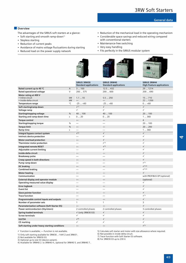
4
4/3
SIRIUS 3RW30 SIRIUS 3RW40 SIRIUS 3RW44Standard applications Standard applications High-Feature applications
Rated current up to 40 °C A 3 ... 100 12.5 ... 432 29 ... 1214Rated operational voltage V 200 ... 575 200 ... 600 200 ... 690
Motor rating at 400 V• Inline circuit kW 1.1 ... 55 5.5 ... 250 15 ... 710• Inside-delta circuit kW — — 22 ... 1200Temperature range °C -25 ... +60 -25 ... +60 0 ... +60
Soft starting/ramp-down 1)
Voltage ramp
Starting/stopping voltage % 40 ... 100 40 ... 100 20 ... 100Starting and ramp-down time s 0 ... 20 0 ... 20 1 ... 360
Torque control — — 4Starting/stopping torque % — — 20 ... 100
Torque limit % — — 20 ... 200Ramp time s — — 1 ... 360
Integral bypass contact system 2)
Intrinsic device protection —
Motor overload protection —Thermistor motor protection — 3)
Integrated remote RESET — 4)
Adjustable current limiting —
Inside-delta circuit — —Breakaway pulse — —
Creep speed in both directions — —Pump ramp-down — — 5)
DC braking — — 5) 6)
Combined braking — — 5) 6)
Motor heating — —Communication — — with PROFIBUS DP (optional)
External display and operator module — — (optional)Operating measured value display — —
Error logbook — —Event list — —
Slave pointer function — —Trace function — — 7)
Programmable control inputs and outputs — —Number of parameter sets 1 1 3
Parameterization software (Soft Starter ES) — —Power semiconductors (thyristors) 2 controlled phases 2 controlled phases 3 controlled phases
Spring-loaded terminals (only 3RW30 03)Screw terminals
UL/CSA 8)
CE marking
Soft starting under heavy starting conditions — — 5)
General data
3RW Soft Starters
Overview
The advantages of the SIRIUS soft starters at a glance:• Soft starting and smooth ramp-down1)
• Stepless starting• Reduction of current peaks• Avoidance of mains voltage fluctuations during starting• Reduced load on the power supply network
• Reduction of the mechanical load in the operating mechanism• Considerable space savings and reduced wiring compared
with conventional starters• Maintenance-free switching• Very easy handling• Fits perfectly in the SIRIUS modular system
Function is available; — Function is not available.
1) Only soft starting available for 3RW30 ..-1AA12 and 3RW31.2) Not available for 3RW30 03.3) Optional up to size S3 (device variant).4) Available for 3RW40 2. to 3RW40 4.; optional for 3RW40 5. and 3RW40 7..
5) Calculate soft starter and motor with size allowance where required.6) Not possible in inside-delta circuit.7) Trace function with Soft Starter ES software.8) For 3RW30 03 up to 230 V.

4
4/4
Overview
3RW30for standard applications
3RW Soft Starters
Various versions of the SIRUS 3RW30 soft starters are available:
• Standard version for fixed speed three-phase motors, sizesS00, S0, S2 and S3
• Version for fixed-speed three-phase motors in a 22.5 mmenclosure
SIRIUS 3RW30 for three-phase motors
Soft starters rated up to 55 kW (at 400 V) for standardapplications in three-phase networks. Extremely small sizes, lowpower losses and simple commissioning are just a few of themany advantages of this soft starter.
Application
The SIRIUS 3RW30 solid-state soft starters are suitable for softstarting and stopping of three-phase asynchronous machines.
Due to two-phase control, the current is kept at minimum valuesin all three phases throughout the entire starting time. Due tocontinuous voltage influencing, current and torque peaks, whichare unavoidable in the case of star-delta starters, for instance,do not occur.
Application areas
• Fans
• Pumps
• Building/construction machines
• Presses
• Escalators
• Transport systems
• Air conditioning systems
• Fans
• Assembly lines
• Compressors and coolers
• Operating mechanisms

4
4/5
3RW30for standard applications
3RW Soft Starters
Selection and ordering data
3RW30 03-2CB54 3RW30 25-1AB14 3RW30 35-1AB14 3RW30 35-1AA12
Ambient temperature 40 °C Ambient temperature 50 °C Size Order No.
Rated Rated power of induction Rated Rated power of inductionoperational motors for rated operational operational motors for rated operationalcurrent Ie voltage Ue current Ie voltage Ue
115 V 230 V 400 V 500 V 115 V 200 V 230 V 460 V 575 V
A kW kW kW W A hp hp hp hp hp
Soft starters for easy starting conditions and high switching frequency,rated operational voltage Ue 200 ... 400 V
3 — 0.55 1.1 — 2.6 — 0.5 0.5 — — 22.5 mm 3RW30 03- CB54
Order No. supplement for connection types
With screw terminals 1
With spring-loaded terminals 2
Ambient temperature 40 °C Ambient temperature 50 °C Size Order No.
Rated Rated power of induction Rated Rated power of inductionoperational motors for rated operational operational motors for rated operationalcurrent Ie voltage Ue current Ie voltage Ue
115 V 230 V 400 V 500 V 115 V 200 V 230 V 460 V 575 V
A kW kW kW W A hp hp hp hp hp
Soft starters for three-phase aynchronous motors, rated operational voltage Ue 200 ... 460 V
6 — 1.5 3 — 4.8 — 1 1 3 — S00 3RW30 14-1CB 4
9 — 2.2 4 — 7.8 — 2 2 5 — S00 3RW30 16-1CB 4
12.5 — 3 5.5 — 11 — 3 3 7.5 — S0 3RW30 24-1AB 4
16 — 4 7.5 — 14 — 3 3 10 — S0 3RW30 25-1AB 4
25 — 5.5 11 — 21 — 5 5 15 — S0 3RW30 26-1AB 4
32 — 7.5 15 — 27 — 7.5 7.5 20 — S2 3RW30 34-1AB 4
38 — 11 18.5 — 32 — 7.5 10 20 — S2 3RW30 35-1AB 4
45 — 11 22 — 38 — 10 10 25 — S2 3RW30 36-1AB 4
63 — 18.5 30 — 54 — 15 20 40 — S3 3RW30 44-1AB 4
75 — 22 37 — 64 — 20 20 40 — S3 3RW30 45-1AB 4
100 — 30 55 — 85 — 25 30 60 — S3 3RW30 46-1AB 4
Soft starters for three-phase asynchronous motors, rated operational voltage Ue 460 ... 575 V
12.5 — — — 7.5 11 — — — 7.5 10 S0 3RW30 24-1AB 5
16 — — — 11 14 — — — 10 10 S0 3RW30 25-1AB 5
25 — — — 15 21 — — — 15 15 S0 3RW30 26-1AB 5
32 — — — 18.5 27 — — — 20 25 S2 3RW30 34-1AB 5
38 — — — 22 32 — — — 20 30 S2 3RW30 35-1AB 5
45 — — — 30 38 — — — 25 30 S2 3RW30 36-1AB 5
63 — — — 37 54 — — — 40 50 S3 3RW30 44-1AB 5
75 — — — 55 64 — — — 40 60 S3 3RW30 45-1AB 5
100 — — — 70 85 — — — 60 75 S3 3RW30 46-1AB 5
Order No. supplement for rated control supply voltage Us
24 V AC/DC 0
110 ... 230 V AC/DC 1
Note:Selection of the soft starter depends on the rated motor current.
The SIRIUS 3RW3 solid-state soft starters are designed for easystarting conditions. JLoad < 10 x JMotor. In the event of deviatingconditions or increased switching frequency, it may be
necessary to choose a larger device. Siemens recommends theuse of the selection and simulation program Win-Soft Starter.For information about rated currents for ambient temperatures> 40 °C, see Technical Information.

4
4/6
Accessories
For Size Version Order No. Weight persoft starters PU approx.
Type kg
Fans1)
3RW3. 2. S0 To increase switching frequency and for device mounting 3RW39 26-8A 0.0083RW30 3. S2 in positions different from the normal position. 3RW39 36-8A 0.030and S3 The fan is snapped into the enclosure from below.3RW30 4. During operation, (control input “IN” at potential A1),
the fan is running. After a stop, the fan continues to3RW39 26-8A run for about another 60 minutes.
3RW39 36-8A
Covers
Terminal covers for box terminals
3RW30 3. S2 Additional touch protection to be fitted at the 3RT19 36-4EA2 0.0203RW30 4. S3 box terminals 3RT19 46-4EA2 0.025
(2 units required per device)
3RT19 36-4EA2
Terminal covers for cable lugs and busbar connection
3RW30 4. S3 For complying with the phase clearances and as 3RT19 46-4EA1 0.040touch protection if box terminal is removed(2 units required per contactor)
3RT19 46-4EA1
Link modules
Electrical and mechanical link between motorstarter protector and soft starter.
Single-unit packaging
3RW30 1.. S00 3RA19 11-1AA00 0.0273RW30 2.. S0 3RA19 21-1AA00 0.037
3RA19 11-1A 3RW30 3.. S2 3RA19 31-1AA00 0.0423RW30 4.. S3 3RA19 41-1AA00 0.090
3RA19 21-1A
Covers and push-in lugs (only for 3RW30 03)
Sealable covers For securing against unauthorized For devices 3RP1 902 0.004adjustment of setting knobs with1 or 2 CO
contacts
3RP1 902 Push-in lugs For devices 3RP1 903 0.002for screw mounting with 1 or 2 CO
contacts
3RP1 903
3RW30for standard applications
3RW Soft Starters

4
4/7
3RW30for standard applications
3RW Soft Starters
Configuration
The 3RW solid-state motor controllers are designed for easystarting conditions. In the event of deviating conditions orincreased switching frequency, it may be necessary tochoose a larger device. For accurate dimensioning, usethe Win-Soft Starter selection and simulation program.
If necessary, an overload relay for heavy starting must beselected where long starting times are involved. PTC sensors arerecommended. This also applies for the smooth ramp-downbecause during the ramp-down time an additional currentloading applies in contrast to free ramp-down.
In the motor feeder between the SIRIUS 3RW soft starter and themotor, no capacitive elements are permitted (e.g. no reactive-power compensation equipment). In addition, neither staticsystems for reactive-power compensation nor dynamic PFC(Power Factor Correction) must be operated in parallel duringstarting and ramp-down of the soft starter. This is important toprevent faults arising on the compensation equipment and/orthe soft starter.
All elements of the main circuit (such as fuses, controls andoverload relays) should be dimensioned for direct starting,following the local short-circuit conditions. Fuses, switchingdevices and overload relays must be ordered separately.Please observe the maximum switching frequencies specifiedin the technical specifications.
Note:
When induction motors are switched on, voltage drops occur asa rule on starters of all types (direct starters, star-delta starters,soft starters). The infeed transformer must always bedimensioned such that the voltage dip when starting the motorremains within the permissible tolerance. If the infeedtransformer is dimensioned with only a small margin, it is bestfor the control voltage to be supplied from a separate circuit(independently of the main voltage) in order to avoid thepotential switching off of the soft starter.
Power electronics circuit diagram1)
More information
Status graphs
L1
NS
B0_
0041
0b
L2 L3
T1 T2 T3
1) Schematic circuit diagram applies to sizes S0 and S2;for size S00, phase L3 is bridged;for size S3, phase L2 is bridged.
Control with a PLC
When a 3RW30 is operated with a triac output or thyristoroutput, the leakage current at the PLC output should be < 1 mAbecause otherwise the 3RW30 will interpret the resultantvoltage drop at the input as an “On command”. As a correctivemeasure for PLC outputs with a higher leakage current, an RCelement with > 100 nF and 220 W can be connected in seriesbetween “IN1” and terminal “A2” of the 3RW30 (Order No.: 3TX7462-3T, see Selection and Ordering Data).
Win-Soft Starter selection and simulation program
With this software, you can simulate and select all Siemens softstarters, taking into account various parameters such as mainsproperties, motor and load data, and special applicationrequirements.
The software is a valuable tool, which makes complicated,lengthy manual calculations for determining the required softstarters superfluous.
The Win-Soft Starter CD-ROM can be downloaded free of chargefromwww.siemens.com/lowvoltage/demosoftware
�
�
��
��
����� ������
��
�
�
�
� ���
����� ������
� ���
3RW30 – 3-phase motor
Auxiliary contacts(sizes S0 to S3 only)
3RW31
�
�
��
��
��� ���
���
�
��

4
4/8
3RW40for standard applications
3RW Soft Starters
Overview
SIRIUS 3RW40 soft starters offer all the same advantages as the3RW30 soft starters. This also applies to the integrated bypasscontact system. At the same time they come with additionalfunctions, e.g. solid-state motor overload and intrinsic deviceprotection and adjustable current limiting, optional thermistormotor protection (up to size S3), integrated remote RESET (up tosize S3), as well as a two-phase control method (PolarityBalancing) that is unique in this performance range.
SIRIUS 3RW40 soft starters are part of the SIRIUS modularsystem. This results in advantages such as identical sizes and auniform connection method. Thanks to their particularlycompact design, SIRIUS 3RW40 soft starters are only half as bigas comparable star-delta starters. Hence, they can be mountedin minimum space in the control cabinet. Configuring andmounting are carried out quickly and easily thanks to the 3-wireconnection.
SIRIUS 3RW40 for three-phase motors
Soft starters rated up to 250 kW (at 400 V) for standardapplications in three-phase networks. Extremely small sizes, lowpower losses and simple commissioning are just three of themany advantages of the SIRIUS 3RW40 soft starters.
“Increased safety” type of protection EEx e according toATEX directive 94/9/EC
The 3RW40 soft starters size S6, S10 and S12 are suitable forstarting explosion-proof motors with “increased safety” type ofprotection EEx e.
Application
The SIRIUS 3RW40 solid-state soft starters are suitable for softstarting and stopping of three-phase asynchronous motors.
Due to two-phase control, the current is kept at minimum valuesin all three phases throughout the entire starting time anddisturbing direct current components are eliminated in addition.This not only enables the two-phase starting of motors up to250 kW (at 400 V) but also avoids the current and torque peakswhich occur e.g. with star-delta starters.
Application areas
• Fans
• Pumps
• Building/construction machines
• Presses
• Escalators
• Transport systems
• Air conditioning systems
• Fans
• Assembly lines
• Compressors and coolers
• Operating mechanisms

4
4/9
3RW40for standard applications
3RW Soft Starters
Selection and ordering data
3RW40 28-1BB14 3RW40 38-1BB14 3RW40 47-1BB14
Ambient temperature 40 °C Ambient temperature 50 °C Size Order No. Weight per
Rated Rated power of induction Rated Rated power of induction PU approx.
operational motors for rated operational operational motors for rated operationalcurrent Ie voltage Ue current Ie voltage Ue
230 V 400 V 500 V 200 V 230 V 460 V 575 V
A kW kW kW A hp hp hp hp kg
Inline circuit, rated operational voltage 200 ... 480 V
12.5 3 5.5 — 11 3 3 7.5 — S0 3RW40 24- B 4 0.77025 5.5 11 — 23 5 5 15 — 3RW40 26- B 4 0.770
32 7.5 15 — 29 7.5 7.5 20 — 3RW40 27- B 4 0.77038 11 18.5 — 34 10 10 25 — 3RW40 28- B 4 0.770
45 11 22 — 42 10 15 30 — S2 3RW40 36- B 4 1.35063 18.5 30 — 58 15 20 40 — 3RW40 37- B 4 1.35072 22 37 — 62 20 20 40 — 3RW40 38- B 4 1.350
80 22 45 — 73 20 25 50 — S3 3RW40 46- B 4 1.900106 30 55 — 98 30 30 75 — 3RW40 47- B 4 1.900
Inline circuit, rated operational voltage 400 ... 600 V
12.5 — 5.5 7.5 11 — — 7.5 10 S0 3RW40 24- B 5 0.77025 — 11 15 23 — — 15 20 3RW40 26- B 5 0.770
32 — 15 18.5 29 — — 20 25 3RW40 27- B 5 0.77038 — 18.5 22 34 — — 25 30 3RW40 28- B 5 0.770
45 — 22 30 42 — — 30 40 S2 3RW40 36- B 5 1.35063 — 30 37 58 — — 40 50 3RW40 37- B 5 1.35072 — 37 45 62 — — 40 60 3RW40 38- B 5 1.350
80 — 45 55 73 — — 50 60 S3 3RW40 46- B 5 1.900106 — 55 75 98 — — 75 75 3RW40 47- B 5 1.900
Order No. supplement for connection types
• With screw terminals 1
Order No. supplement for rated control supply voltage Us
• 24 V AC/DC 0• 110 ... 230 V AC/DC 1
Order No. supplement for option of thermistor motor protection
• With thermistor motor protection T
• With thermistor motor protection B
Note:Selection of the soft starter depends on the rated motor current.
The SIRIUS 3RW40 solid-state soft starters are designed for easystarting conditions. JLoad < 10 x JMotor. In the event of deviatingconditions or increased switching frequency, it may benecessary to choose a larger device. Siemens recommends theuse of the selection and simulation program Win-Soft Starter.For information about rated currents for ambient temperatures> 40 °C, see technical specifications (see Technical Information).

4
4/10
3RW40 56-6BB44 3RW40 76-6BB44
3RW40for standard applications
3RW Soft Starters
Ambient temperature 40 °C Ambient temperature 50 °C Size Order No. Weight per
Rated Rated power of induction Rated Rated power of induction PU approx.
operational motors for rated operational operational motors for rated operationalcurrent Ie voltage Ue current Ie voltage Ue
230 V 400 V 500 V 200 V 230 V 460 V 575 V
A kW kW W A hp hp hp hp kg
Inline circuit, rated operational voltage 200 ... 460 V
134 37 75 — 117 30 40 75 — S6 3RW40 55- BB 4 4.900162 45 90 — 145 40 50 100 — 3RW40 56- BB 4 6.900
230 75 132 — 205 60 75 150 — S12 3RW40 73- BB 4 8.900280 90 160 — 248 75 100 200 — 3RW40 74- BB 4 8.900
356 110 200 — 315 100 125 250 — 3RW40 75- BB 4 8.900432 132 250 — 385 125 150 300 — 3RW40 76- BB 4 8.900
Inline circuit, rated operational voltage 400 ... 600 V
134 — 75 90 117 — — 75 100 S6 3RW40 55- BB 5 4.900162 — 90 110 145 — — 100 150 3RW40 56- BB 5 6.900
230 — 132 160 205 — — 150 200 S12 3RW40 73- BB 5 8.900280 — 160 200 248 — — 200 250 3RW40 74- BB 5 8.900
356 — 200 250 315 — — 250 300 3RW40 75- BB 5 8.900432 — 250 315 385 — — 300 400 3RW40 76- BB 5 8.900
Order No. supplement for connection types
• With spring-loaded terminals 2• With screw terminals 6
Order No. supplement for the rated control supply voltage Us1)
• 115 V AC 3• 230 V AC 4
1) Control by way of the internal 24 V DC supply and direct control by meansof PLC possible.
Note:Selection of the soft starter depends on the rated motor current.
The SIRIUS 3RW40 solid-state soft starters are designed for easystarting conditions. JLoad < 10 x JMotor. In the event of deviatingconditions or increased switching frequency, it may benecessary to choose a larger device. Siemens recommends theuse of the selection and simulation program Win-Soft Starter.For information about rated currents for ambient temperatures> 40 °C, see technical specifications (see Technical Information).

4
4/11
3RW40for standard applications
3RW Soft Starters
Accessories
For soft starters Version Order No. Weight perType Size PU approx.
kg
Box terminal blocks for soft starters
For round and ribbon cables
3RW40 5. S6 • Up to 70 mm2 3RT19 55-4G 0.230• Up to 120 mm2 3RT19 56-4G 0.260
3RW40 7. S12 • Up to 240 mm2 3RT19 66-4G 0.676
Auxiliary terminals
Auxiliary terminals, 3-pole
3RW40 4. S3 3RT19 46-4F 0.035
Covers for soft starters
Terminal covers for box terminals
Additional touch protection to be fitted at the box terminals(2 units required per device)
3RW40 3. S2 3RT19 36-4EA2 0.0203RW40 4. S3 3RT19 46-4EA2 0.0253RW40 5. S6 3RT19 56-4EA2 0.0303RW40 7. S12 3RT19 66-4EA2 0.040
Terminal covers for cable lugs and busbar connection
3RW30 4. S3 For complying with the phase clearances and as 3RT19 46-4EA1 0.040
3RW40 5. S6 touch protection if box terminal is removed 3RT19 56-4EA1 0.0703RW40 7. S12 (2 units required per contactor) 3RT19 66-4EA1 0.130
Sealing covers
3RW40 2. to S0, 3RW49 00-0PB10 0.0053RW40 4. S2,
S3
3RW40 5. and S6, 3RW49 00-0PB00 0.0103RW40 7. S12
Modules for RESET1)
Modules for remote RESET, electrical
Operating range 0.85 ... 1.1 x Us,power consumption AC 80 VA, DC 70 W,ON period 0.2 s ... 4 s,switching frequency 60/h
3RW40 5. and S6, • 24 V ... 30 V AC/DC 3RU19 00-2AB71 0.0663RW40 7. S12 • 110 V ... 127 V AC/DC 3RU19 00-2AF71 0.067
• 220 V ... 250 V AC/DC 3RU19 00-2AM71 0.066
3RW40 5. and S6, • Resetting plunger, holder and former 3RU19 00-1A 0.0383RW40 7. S12 • Suitable pushbutton IP65, 3SB30 00-0EA11 0.020
• Ø 22 mm, 12 mm stroke• Extension plunger 3SX13 35 0.004
Cable releases with holder for RESET
For Ø 6.5 mm holes in the control panel;max. control panel thickness 8 mm
3RW40 5. and S6, • Length 400 mm 3RU19 00-1B 0.0633RW40 7. S12 • Length 600 mm 3RU19 00-1C 0.073
1) Remote RESET already integrated in the 3RW40 2. to 3RW40 4. soft starters.

4
4/12
For soft starters Motor protection circuit breaker - 3RV Order No. Weight perType Size Size PU approx.
kg
Link modules for motor protection circuit breaker - 3RV
3RW40 24, S0 S0 3RA19 21-1A 0.0283RW40 26
3RW40 27, S2 3RA19 31-1D 0.0413RW40 28
3RW40 36 S2 S2 3RA19 31-1A 0.033
3RW40 37, S3 3RA19 41-1D 0.0423RW40 38
3RW40 46, S3 S3 3RA19 41-1A 0.0723RW40 47
Fans (to increase switching frequency and for device mounting in positions differentfrom the normal position)
3RW40 2. S0 3RW49 28-8VB00 0.010
3RW40 3., S2, 3RW49 47-8VB00 0.0203RW40 4. S3
Operating instructions1)
For soft starters
3RW40 2. S0 3ZX10 12-0RW40-1AA1 on req.3RW40 3. S23RW40 4. S3
3RW40 5. S63RW40 7. S12 3ZX10 12-0RW40-2DA1 on req.
1) The operating instructions are included in the scope of supply.
Spare parts
3RW40for standard applications
3RW Soft Starters
For soft starters Version Order No. Weight perType Size Rated control supply voltage Us PU approx.
kg
Fans
Fans
3RW40 5.-.BB3. S6 115 V AC 3RW49 36-8VX30 0.3003RW40 5.-.BB4. S6 230 V AC 3RW49 36-8VX40 0.300
3RW40 7.-.BB3. S12 115 V AC 3RW49 47-8VX30 0.5003RW40 7.-.BB4. S12 230 V AC 3RW49 47-8VX40 0.500
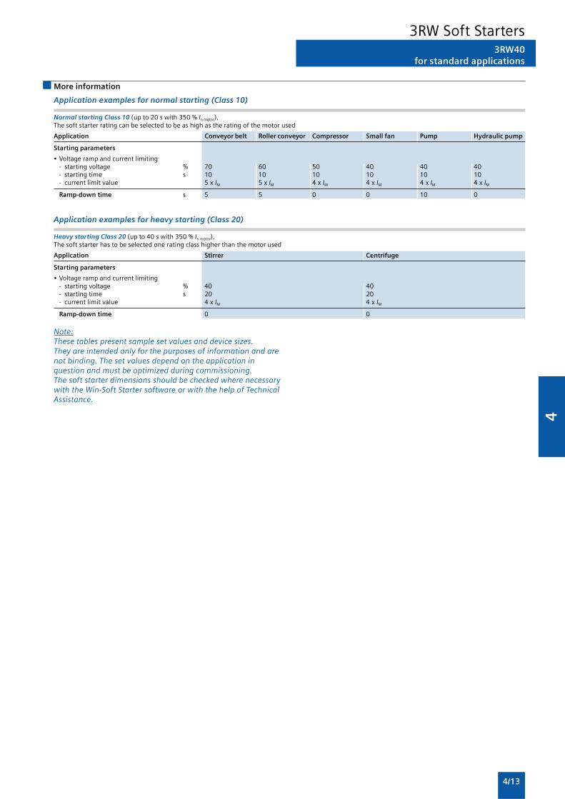
4
4/13
3RW40for standard applications
3RW Soft Starters
More information
Application examples for normal starting (Class 10)
Normal starting Class 10 (up to 20 s with 350 % In motor),The soft starter rating can be selected to be as high as the rating of the motor used
Application Conveyor belt Roller conveyor Compressor Small fan Pump Hydraulic pump
Starting parameters
• Voltage ramp and current limiting- starting voltage % 70 60 50 40 40 40- starting time s 10 10 10 10 10 10- current limit value 5 x IM 5 x IM 4 x IM 4 x IM 4 x IM 4 x IM
Ramp-down time s 5 5 0 0 10 0
Application examples for heavy starting (Class 20)
Heavy starting Class 20 (up to 40 s with 350 % In motor),The soft starter has to be selected one rating class higher than the motor used
Application Stirrer Centrifuge
Starting parameters
• Voltage ramp and current limiting- starting voltage % 40 40- starting time s 20 20- current limit value 4 x IM 4 x IM
Ramp-down time 0 0
Note:These tables present sample set values and device sizes.They are intended only for the purposes of information and arenot binding. The set values depend on the application inquestion and must be optimized during commissioning.The soft starter dimensions should be checked where necessarywith the Win-Soft Starter software or with the help of TechnicalAssistance.

4
4/14
Configuration
The 3RW solid-state soft starters are designed for easy startingconditions. In the event of deviating conditions or increasedswitching frequency, it may be necessary to choose a largerdevice. For accurate dimensioning, use the Win-Soft Starterselection and simulation program.
Where long starting times are involved, the integrated solid-state overload relay for heavy starting should not bedisconnected. PTC sensors are recommended. This also appliesfor the smooth ramp-down because during the ramp-down timean additional current loading applies in contrast to free ramp-down.
In the motor feeder between the SIRIUS 3RW soft starter and themotor, no capacitive elements are permitted (e.g. no reactive-power compensation equipment). In addition, neither staticsystems for reactive-power compensation nor dynamic PFC(Power Factor Correction) must be operated in parallel duringstarting and ramp-down of the soft starter. This is important toprevent faults arising on the compensation equipment and/orthe soft starter.
All elements of the main circuit (such as fuses and controls)should be dimensioned for direct starting, following the localshort-circuit conditions. Fuses, controls and overload relays mustbe ordered separately. Please observe the maximum switchingfrequencies specified in the technical specifications.
Note:
When induction motors are switched on, voltage drops occur asa rule on starters of all types (direct starters, star-delta starters,soft starters). The infeed transformer must always bedimensioned such that the voltage dip when starting the motorremains within the permissible tolerance. If the infeedtransformer is dimensioned with only a small margin, it is bestfor the control voltage to be supplied from a separate circuit(independently of the main voltage) in order to avoid thepotential switching off of the soft starter.
Schematic circuit diagram
3RW40for standard applications
3RW Soft Starters
L1
NS
B0_
0014
85a
L2 L3
T1 T2 T3
A bypass contact system and solid-state overload relay arealready integrated in the 3RW40 soft starter and therefore donot have to be ordered separately.
Status graphs
����
��
����� �
���
��
����� ������
����� ������
��� ������� ��
����������� ��
�
���
����
�
�
�
Win-Soft Starter selection and simulation program
With this software, you can simulate and select all Siemens softstarters, taking into account various parameters such as mainsproperties, motor and load data, and special applicationrequirements.
The software is a valuable tool, which makes complicated,lengthy manual calculations for determining the required softstarters superfluous.
The Win-Soft Starter CD-ROM can be downloaded free of chargefrom
www.siemens.com/lowvoltage/demosoftware
You can find more information on the Internet at:http://www.siemens.com/softstarter

4
4/15
3RW44for High-Feature applications
3RW Soft Starters
Overview
In addition to soft starting and soft ramp-down, the solid-stateSIRIUS 3RW44 soft starters provide numerous functions forhigher-level requirements. They cover a performance range upto 710 kW (at 400 V) in the inline circuit and up to 1200 kW(at 400 V) in the inside-delta circuit.
The SIRIUS 3RW44 soft starters are characterized by a compactdesign for space-saving and clearly arranged control cabinetlayouts. For optimized motor starting and stopping theinnovative SIRIUS 3RW44 soft starters are an attractivealternative with considerable savings potential compared toapplications with a frequency converter. The new torque controland adjustable current limiting enable the High-Feature softstarters to be used in nearly every conceivable task. Theyguarantee the reliable avoidance of sudden torque applicationsand current peaks during motor starting and stopping. Thiscreates savings potential when calculating the size of theswitchgear and when servicing the machinery installed. Be it forinline circuits or inside-delta circuits – the SIRIUS 3RW44 softstarter offers savings especially in terms of size and equipmentcosts.
The bypass contacts already integrated in the soft starter bypassthe thyristors after a motor ramp-up is detected. This results in afurther great reduction in the heat loss occuring duringoperation of the soft starter at rated value.
Combinations of various starting, operating and ramp-downpossibilities ensure an optimum adaptation to the application-specific requirements. Operating and commissioning can beperformed by means of the user-friendly keypad and a menu-prompted, multi-line graphic display with background lighting.The optimized motor ramp-up and ramp-down can be effectedby means of just a few settings with a previously selectedlanguage. Four-key operation and plain-text displays for eachmenu point guarantee full clarity at every moment of theparameterization and operation.
Applicable standards
• IEC 60947-4-2
• UL/CSA
Application
The SIRIUS 3RW44 solid-state soft starters are suitable for thetorque-controlled soft starting and smooth ramp-down as wellas braking of three-phase asynchronous motors.
Application areas, e.g.
• Pumps
• Fans
• Compressors
• Water transport
• Conveying systems and lifts
• Hydraulics
• Machine tools
• Mills
• Saws
• Breakers
• Mixers
• Centrifuges
• Industrial cooling and refrigerating systems

4
4/16
Selection and ordering data
3RW44for High-Feature applications
3RW Soft Starters
3RW44 27-1BC44 3RW44 36-6BC44 3RW44 47-6BC44 3RW44 58-6BC44 3RW44 66-6BC44
1) Control by way of the internal 24 V DC supply and direct control by meansof PLC possible.
Note:
Soft starter selection depends on the rated motor current.
The 3RW44 solid-state soft starters are designed for normal starting(Class 10). (Inertia load of the overall operating mechanismJLoad <10 x JMotor; starting current 350 % x Ie for 20 s similar load). Forany other conditions of use, the devices should be selected usingthe Win-Soft Starter selection and simulation program.See Technical Specifications for information about rated currentsfor ambient temperatures >40 °C and switching frequency.
Ambient temperature 40 °C Ambient temperature 50 °C Order No. Weight per
Rated Rated power of induction Rated Rated power of induction PU approx.
operational motors for rated operational operational motors for rated operationalcurrent Ie voltage Ue current Ie voltage Ue
230 V 400 V 500 V 690 V 1000 V 200 V 230 V 460 V 575 V
A kW kW kW kW kW A hp hp hp hp kg
Inline circuit, rated operational voltage 200 ... 460 V
29 5.5 15 — — — 26 7.5 7.5 15 — 3RW44 22- BC 6.50036 7.5 18.5 — — — 32 10 10 20 — 3RW44 23- BC 6.50047 11 22 — — — 42 10 15 25 — 3RW44 24- BC 6.500
57 15 30 — — — 51 15 15 30 — 3RW44 25- BC 6.50077 18.5 37 — — — 68 20 20 50 — 3RW44 26- BC 6.50093 22 45 — — — 82 25 25 60 — 3RW44 27- BC 6.500
Order No. supplement for connection types
• With spring-loaded terminals 3• With screw terminals 1
113 30 55 — — — 100 30 30 75 — 3RW44 34- BC 7.900134 37 75 — — — 117 30 40 75 — 3RW44 35- BC 7.900162 45 90 — — — 145 40 50 100 — 3RW44 36- BC 7.900
203 55 110 — — — 180 50 60 125 — 3RW44 43- BC 11.500250 75 132 — — — 215 60 75 150 — 3RW44 44- BC 11.500313 90 160 — — — 280 75 100 200 — 3RW44 45- BC 11.500
356 110 200 — — — 315 100 125 250 — 3RW44 46- BC 11.500432 132 250 — — — 385 125 150 300 — 3RW44 47- BC 11.500
551 160 315 — — — 494 150 200 400 — 3RW44 53- BC 50.000615 200 355 — — — 551 150 200 450 — 3RW44 54- BC 50.000693 200 400 — — — 615 200 250 500 — 3RW44 55- BC 50.000
780 250 450 — — — 693 200 250 600 — 3RW44 56- BC 50.000880 250 500 — — — 780 250 300 700 — 3RW44 57- BC 50.000970 315 560 — — — 850 300 350 750 — 3RW44 58- BC 50.000
1076 355 630 — — — 970 350 400 850 — 3RW44 65- BC 78.0001214 400 710 — — — 1076 350 450 950 — 3RW44 66- BC 78.000
Order No. supplement for connection types
• With spring-loaded terminals 2• With screw terminals 6
Order No. supplement for the rated control supply voltage Us1)
• 115 V AC 3• 230 V AC 4
Order No. supplement for operational voltage
• 200 ... 460 V 4• 400 ... 600 V 5• 400 ... 690 V 6

4
4/17
3RW44for High-Feature applications
3RW Soft Starters
3RW44 27-1BC44 3RW44 36-6BC44 3RW44 47-6BC44 3RW44 58-6BC44 3RW44 66-6BC44
Ambient temperature 40 °C Ambient temperature 50 °C Order No. Weight per
Rated Rated power of induction Rated Rated power of induction PU approx.
operational motors for rated operational operational motors for rated operationalcurrent Ie
1) voltage Ue current Ie voltage Ue
230 V 400 V 500 V 690 V 1000 V 200 V 230 V 460 V 575 V
A kW kW kW kW kW A hp hp hp hp kg
Inside-delta circuit, rated operational voltage 200 ... 460 V
50 15 22 — — — 45 10 15 30 — 3RW44 22- BC 6.50062 18.5 30 — — — 55 15 20 40 — 3RW44 23- BC 6.50081 22 45 — — — 73 20 25 50 — 3RW44 24- BC 6.500
99 30 55 — — — 88 25 30 60 — 3RW44 25- BC 6.500133 37 75 — — — 118 30 40 75 — 3RW44 26- BC 6.500161 45 90 — — — 142 40 50 100 — 3RW44 27- BC 6.500
Order No. supplement for connection types
• With spring-loaded terminals 3• With screw terminals 1
196 55 110 — — — 173 50 60 125 — 3RW44 34- BC 7.900232 75 132 — — — 203 60 75 150 — 3RW44 35- BC 7.900281 90 160 — — — 251 75 100 200 — 3RW44 36- BC 7.900
352 110 200 — — — 312 100 125 250 — 3RW44 43- BC 11.500433 132 250 — — — 372 125 150 300 — 3RW44 44- BC 11.500542 160 315 — — — 485 150 200 400 — 3RW44 45- BC 11.500
617 200 355 — — — 546 150 200 450 — 3RW44 46- BC 11.500748 250 400 — — — 667 200 250 600 — 3RW44 47- BC 11.500
954 315 560 — — — 856 300 350 750 — 3RW44 53- BC 50.0001065 355 630 — — — 954 350 400 850 — 3RW44 54- BC 50.0001200 400 710 — — — 1065 350 450 950 — 3RW44 55- BC 50.000
1351 450 800 — — — 1200 450 500 1050 — 3RW44 56- BC 50.0001524 500 900 — — — 1351 450 600 1200 — 3RW44 57- BC 50.0001680 560 1000 — — — 1472 550 650 1300 — 3RW44 58- BC 50.000
1864 630 1100 — — — 1680 650 750 1500 — 3RW44 65- BC 78.0002103 710 1200 — — — 1864 700 850 1700 — 3RW44 66- BC 78.000
Order No. supplement for connection types
• With spring-loaded terminals 2• With screw terminals 6
Order No. supplement for the rated control supply voltage Us2)
• 115 V AC 3
• 230 V AC 4
Order No. supplement for rated operational voltage
• 200 ... 400 V 4• 400 ... 600 V 5
1) In the selection table, the unit rated current Ie refers to the inductionmotor’s rated operational current in the inside-delta circuit. The actualcurrent of the device is approx. 58% of this value.
2) Control by way of the internal 24 V DC supply and direct control by meansof PLC possible.
Note:
Soft starter selection depends on the rated motor current.
The 3RW44 solid-state soft starters are designed for normalstarting (Class 10). (Inertia load of the overall operatingmechanism JLoad <10 x JMotor; starting current 350 % x Ie for 20 ssimilar load). For any other conditions of use, the devices shouldbe selected using the Win-Soft Starter selection and simulationprogram.See Technical Specifications for information about rated currentsfor ambient temperatures >40 °C and switching frequency.

4
4/18
Accessories
3RW44for High-Feature applications
3RW Soft Starters
For Version Order No. Weight persoft starters PU approx.
Type kg
PC cables
For PC/PG communication with SIRIUS 3RW44 soft starters
Through the system interface, for connecting to the serial interface of the PC/PG 3UF7 940-0AA00-0 0.150
3UF7 940-0AA00-0
PROFIBUS communications modules
Modules can be plugged into the soft starters for integrating the starters 3RW49 00-0KC00 0.320in the PROFIBUS network with DPV1 slave functionality.
On Y-link the soft starter has only DPV0 slave functionality.
3RW49 00-0KC00
External display and operator modules
For indicating and operating the functions provided by the soft starter 3RW49 00-0AC00 0.320using an externally mounted display and operator module(e.g. in the control cabinet door)
Connection cables
From the device interface (serial) of the 3RW44 soft starterto the external display and operator module
3RW49 00-0AC00 • Length 0.5 m, flat 3UF7 932-0AA00-0 0.020• Length 0.5 m, round 3UF7 932-0BA00-0 0.050• Length 1.0 m, round 3UF7 937-0BA00-0 0.100• Length 2.5 m, round 3UF7 933-0BA00-0 0.150
Box terminal blocks for soft starters
Box terminal blocks
3RW44 2. included in the scope of supply
3RW44 3. • Up to 70 mm2 3RT19 55-4G 0.230• Up to 120 mm2 3RT19 56-4G 0.260
3RW44 4. • Up to 240 mm2 3RT19 66-4G 0.676
3RT19
Covers for soft starters
Terminal covers for box terminals
Additional touch protection to be fitted at the box terminals(2 units required per device)
3RW44 2. and 3RT19 56-4EA2 0.0303RW44 3.
3RW44 4. 3RT19 66-4EA2 0.040
Terminal covers for cable lugs and busbar connections
3RW44 2. and 3RT19 56-4EA1 0.0703RW44 3.
3RW44 4. 3RT19 66-4EA1 0.130
3RT19 .6-4EA1
Operating instructions1)
For 3RW44 soft starters 3ZX10 12-0RW44-1AA1
1) The operating instructions are included in the scope of supply.

4
4/19
Overview
3RW44for High-Feature applications
3RW Soft Starters
Easy and clearly arranged parameter setting of the 3RW44 soft starterwith Soft Starter ES 2007
Graphic presentation of measured values with the trace function(oscilloscope function) of Soft Starter ES 2007 Standard and Premium
Soft Starter ES 2007
Soft Starter ES software enables the quick and easyparameterization, monitoring and service-related diagnostics ofSIRIUS 3RW44 High Feature soft starters . The device parameterscan be set directly on the PC and transferred through a serialcable or optional PROFIBUS connection to the soft starter.
The advantages of Soft Starter ES:
• Clear and easily manageable setting of device functions andtheir parameters – online and offline
• Effective diagnostics function of the soft starter and display ofall key measured values
• Trace function (oscilloscope function) for recording measuredvalues and events (in the Soft Starter ES Standard andPremium software versions)
Efficient engineering with new program versions
The Soft Starter ES software program is available in threeversions which differ in user-friendliness, scope of functions andprice.
Soft Starter ES Basic Standard Premium
Access through local interfaceon the device
Parameterizing
Operating
Diagnostics
Creating typicals — 1)
Exporting parameters —
Comparative functions —
Standard-conform printout —according to EN ISO 7200
Service data (slave pointer, —statistics data)
Access through PROFIBUS — —
Group function — —
Teleservice via MPI — —
S7 routing — —
STEP7 Object Manager — —
1) Typicals with Service Pack 1 and higher.
More functions
• Standard-conform printoutsThe software tool makes machine documentation far easier.Parameterization printouts according to EN ISO 7200 arepossible. The elements to be printed are easy to select andcompile as required.
• Easy creating of typicalsTypicals can be created for devices and applications withparameters which differ only slightly. These typicals containall the parameters needed for the parameterization. Inaddition it is possible to specify which of these parameters arefixed default values and which can still be adapted by thestart-up engineer.
• Group functionFor the user-friendly parameterization of numerous devices orapplications of the same type, the programs of the SIRIUS ESsoftware family provide a group function which enables theparameterization of several devices to be read out or writtenthrough PROFIBUS. In conjunction with typicals it is evenpossible to selectively adapt the parameters in any number ofparameterizations.
• Teleservice via MPIThe Soft Starter ES premium version supports the use of MPITeleservice (consisting of the Teleservice software and variousTeleservice adapters) for remote diagnostics of the devices.This facilitates diagnostics and maintenance and shortens theresponse time for service purposes.

4
4/20
3RW44for High-Feature applications
3RW Soft Starters
Types of delivery and license
Soft Starter ES is available as follows:
• Floating license – the license for any one user at any one time
- Authorizes any one user
- Independent of the number of installations (unlike thesingle license which is allowed to be installed once only)
- Only the actual use of the program has to be licensed
- Trial license (free use of all program functions for 14 daysfor test and evaluation purposes, included on every productCD, available in the download file of the SIRIUS ES programin the Service&Support portal).
Following delivery versions are available in addition for SoftStarter ES 2007:
• UpgradeUpgrade from an old to a new version with expandedfunctions, e.g. upgrade from Soft Starter ES 2006 to SoftStarter ES 2007
• PowerpackSpecial pack for switching within the same software version toa more powerful version with more functionality, e.g.Powerpack Soft Starter ES 2007 for switching from Standardto Premium
• Software Update ServiceTo keep you up to date at all times we offer a special servicewhich supplies you automatically with all service packs andupgrades
• License downloadUser-friendly license key download from the A&D Mall(currently only for customers from Germany) as an easy andquick way for you to receive additional licenses for yoursoftware
New licensing procedure
To make licensing easier, the three versions of Soft Starter ES areavailable with immediate effect with the following license:
14 day trial license for Premium functions:for test and evaluation purposes, included on every product CD,available also in the download file of the SIRIUS Soft Starter ES2007 program in the Service&Support portal.
System requirements
Soft Starter ES 2007 parameterization, start-up and diagnostics Basic/Standard Premiumsoftware for the SIRIUS 3RW44 soft starter
Firmware version ≥ *EO4* 1) Firmware version ≥ *EO6* 2)
Operating system Windows 2000 (Service Pack 3 or 4), Windows XP Professional (Service Pack 2)
Processor ≥ Pentium 800 MHz / 1 GHz (Windows VISTA)
Free space on hard disk ≥ 150 MB
CD-ROM/DVD drive Yes (only when installing from CD)
Serial interface (COM) Yes
PC cable/parameterizing cable/connection cable Yes
PROFIBUS communication module (optional) — Yes
1) SIRIUS 3RW44 with firmware version ≥ *E04*. Installed in starters deliveredafter December 2005.
2) SIRIUS 3RW44 with firmware version ≥ *E06*. Installed in starters deliveredafter May 2006.

4
4/21
3RW44for High-Feature applications
3RW Soft Starters
Selection and ordering data
Parameterization and service software for SIRIUS 3RW44 softstarters
• Runs on WIN 2000/WIN XP PROF
• Without PC cable
Version Order No. Weight perPU approx.
kg
Soft Starter ES 2007 Basic
Floating license for one userE-SW, software and documentation on CD, 3 languages(German/English/French), communication through system interface
• License key on USB stick, Class A, including CD 3ZS1 313-4CC10-0YA5 0.230
• License key download, Class A, no CD 3ZS1 313-4CE10-0YB5 0.230
Soft Starter ES 2007 Standard
Floating license for one userE-SW, software and documentation on CD, 3 languages(German/English/French), communication through system interface
• License key on USB stick, Class A, including CD 3ZS1 313-5CC10-0YA5 0.230
• License key download, Class A, no CD 3ZS1 313-5CE10-0YB5 0.230
Upgrade for Soft Starter ES 2006 3ZS1 313-5CC10-0YE5 0.230Floating license for one user, E-SW, software and documentation on CD,License key on USB stick, Class A, 3 languages (German/English/French),communication through system interface
Powerpack for Soft Starter ES 2007 Basic 3ZS1 313-5CC10-0YD5 0.230Floating license for one user, E-SW, software and documentation on CD,License key on USB stick, Class A, 3 languages (German/English/French),communication through system interface
Software Update Service 3ZS1 313-5CC10-0YL5 0.230For 1 year with automatic extension, assuming the current software version is in use,E-SW, software and documentation on CD, communication through system interface
Soft Starter ES 2007 Premium
Floating license for one userE-SW, software and documentation on CD, 3 languages (German/English/French),communication through system interface
• License key on USB stick, Class A, including CD 3ZS1 313-6CC10-0YA5 0.230
• License key download, Class A, no CD 3ZS1 313-6CE10-0YB5 0.230
Upgrade for Soft Starter ES 2006 3ZS1 313-6CC10-0YE5 0.230Floating license for one user, E-SW, software and documentation on CD,License key on USB stick, Class A, 3 languages (German/English/French),communication through system interface
Powerpack for Soft Starter ES 2007 Standard 3ZS1 313-6CC10-0YD5 0.230Floating license for one user, E-SW, software and documentation on CD,License key on USB stick, Class A, 3 languages (German/English/French),communication through system interface
Software Update Service 3ZS1 313-6CC10-0YL5 0.230For 1 year with automatic extension, assuming the current software version is in use,E-SW, software and documentation on CD, communication through system interface
Accessories
PC cables for PC/PG communication, 3UF7940-0AA00-0 0.150through the system interface on the device,for connecting to the serial interface on the PC/PG
Optional PROFIBUS communication modules for SIRIUS 3RW44 3RW4 900-0KC00 0.320

4
4/22
Spare parts
For Version Order No. Weight persoft starters PU approx.
Type kg
Fans
Fans
3RW44 2. and 115 V AC 3RW49 36-8VX30 0.3003RW44 3. 230 V AC 3RW49 36-8VX40 0.300
3RW44 4. 115 V AC 3RW49 47-8VX30 0.500230 V AC 3RW49 47-8VX40 0.500
3RW44 5. and 115 V AC 3RW49 57-8VX30 0.8003RW49 3RW44 6.1) 230 V AC 3RW49 57-8VX40 0.800
3RW44 6.2) 115 V AC 3RW49 66-8VX30 0.300230 V AC 3RW49 66-8VX40 0.300
1) 3RW44 6. mounting on output side.
2) For mounting on front side.
3RW44for High-Feature applications
3RW Soft Starters

4
4/23
More information
3RW44for High-Feature applications
3RW Soft Starters
Application examples for normal starting (Class 10)
Normal starting Class 10 (up to 20 s with 350 % In motor),The soft starter rating can be selected to be as high as the rating of the motor used
Application Conveyor belt Roller conveyor Compressor Small fan Pump Hydraulic pump
Starting parameters
• Voltage ramp andcurrent limiting- starting voltage % 70 60 50 30 30 30- starting time s 10 10 10 10 10 10- current limit value Deactivated Deactivated 4 x IM 4 x IM Deactivated Deactivated
• Torque ramp- starting torque 60 50 40 20 10 10- end torque 150 150 150 150 150 150- starting time 10 10 10 10 10 10
• Breakaway pulse Deactivated (0 ms) Deactivated (0 ms) Deactivated (0 ms) Deactivated (0 ms) Deactivated (0 ms) Deactivated (0 ms)
Ramp-down mode Smooth ramp-down Smooth ramp-down Free ramp-down Free ramp-down Pump ramp-down Free ramp-down
Application examples for heavy starting (Class 20)
Heavy starting Class 20 (up to 40 s with 350 % In motor),The soft starter has to be selected one rating class higher than the motor used
Application Stirrer Centrifuge Milling machine
Starting parameters
• Voltage ramp andcurrent limiting- starting voltage % 30 30 30- starting time s 30 30 30- current limit value 4 x IM 4 x IM 4 x IM
• Torque ramp- starting torque 30 30 30- end torque 150 150 150- starting time 30 30 30
• Breakaway pulse Deactivated (0 ms) Deactivated (0 ms) Deactivated (0 ms)
Ramp-down mode Free ramp-down Free ramp-down Free ramp-down or DC braking
Application examples for very heavy starting (Class 30)
Very heavy starting Class 30 (up to 60 s with 350 % In motor),The soft starter has to be selected two rating classes higher than the motor used
Application Large fan Mill Breakers Circular saw/bandsaw
Starting parameters
• Voltage ramp andcurrent limiting- starting voltage % 30 50 50 30- starting time s 60 60 60 60- current limit value 4 x IM 4 x IM 4 x IM 4 x IM
• Torque ramp- starting torque 20 50 50 20- end torque 150 150 150 150- starting time 60 60 60 60
• Breakaway pulse Deactivated (0 ms) 80 %, 300 ms 80 %, 300 ms Deactivated (0 ms)
Ramp-down mode Free ramp-down Free ramp-down Free ramp-down Free ramp-down
Note:These tables present sample set values and device sizes.They are intended only for the purposes of information and arenot binding. The set values depend on the application inquestion and must be optimized during commissioning.The soft starter dimensions should be checked where necessarywith the Win-Soft Starter software or with the help of TechnicalAssistance.

4
4/24
3RW44for High-Feature applications
3RW Soft Starters
Circuit concept
The SIRIUS 3RW44 soft starters can be operated in two differenttypes of circuits.
• Inline circuitThe controls for isolating and protecting the motor are simplyconnected in series with the soft starter. The motor isconnected to the soft starter with three cables.
• Inside-delta circuitThe wiring is similar to that of star-delta starters. The phasesof the soft starter are connected in series with the individualmotor windings. The soft starter then only has to carry thephase current, amounting to about 58 % of the rated motorcurrent (conductor current).
Comparison of the types of circuits.
� � � � � � � � � �
�
�
�
�
Inline circuit:Rated current Ie corresponds to the rated motor current In,3 cables to the motor
� � � � � � � � � �
�
�
�
�
� � � � � �
�
� �
�
� �
� �
�
�
Inside-delta circuit:Rated current Ie corresponds to approx. 58 % of the rated motor current In,6 cables to the motor (as with star-delta starters)
Which circuit?
Using the inline circuit involves the lowest wiring outlay. If thesoft starter to motor connections are long, this circuit ispreferable.With the inside-delta circuit there is double the wiringcomplexity but a smaller size of device can be used at the samerating.
Thanks to the choice of operating mode between the inlinecircuit and inside-delta circuit, it is always possible to select themost favorable solution.
The braking function is possible only in the inline circuit.
Configuration
The 3RW44 solid-state soft starters are designed for normalstarting. In case of heavy starting or increased startingfrequency, a larger device must be selected.
For long starting times it is recommended to have a PTCthermistor detector in the motor. This also applies for the ramp-down modes smooth ramp-down, pump ramp-down and DCbraking, because during the ramp-down time in these modes,an additional current loading applies in contrast to free ramp-down.
In the motor feeder between the SIRIUS 3RW soft starter and themotor, no capacitive elements are permitted (e.g. no reactive-power compensation equipment). In addition, neither staticsystems for reactive-power compensation nor dynamic PFC(Power Factor Correction) must be operated in parallel duringstarting and ramp-down of the soft starter. This is important toprevent faults arising on the compensation equipment and/orthe soft starter.
All elements of the main circuit (such as fuses and controls)should be dimensioned for direct starting, following the localshort-circuit conditions. Fuses, controls and overload relays mustbe ordered separately.
A bypass contact system and solid-state overload relay arealready integrated in the 3RW44 soft starter and therefore donot have to be ordered separately.
The harmonic component load for starting currents must betaken into consideration for the selection of motor starterprotectors (selection of release).
Note:
When induction motors are switched on, voltage drops occur asa rule on starters of all types (direct starters, star-delta starters,soft starters). The infeed transformer must always bedimensioned such that the voltage dip when starting the motorremains within the permissible tolerance. If the infeedtransformer is dimensioned with only a small margin, it is bestfor the control voltage to be supplied from a separate circuit(independently of the main voltage) in order to avoid thepotential switching off of the soft starter.
Device interface, PROFIBUS DP communication module,Soft Starter ES parameterizing and operating software
The 3RW44 electronic soft starters have a PC interface forcommunicating with the Soft Starter ES software or forconnecting the external display and operator module. If theoptional PROFIBUS communications module is used, the 3RW44soft starter can be integrated in the PROFIBUS network andcommunicate using the GSD file or Soft Starter ES 2007premium software.
Manual for SIRIUS 3RW44
Besides containing all important information on configuring,commissioning and servicing, the manual also contains examplecircuits and the technical specifications for all devices.
Win-Soft Starter selection and simulation program
With this software, you can simulate and select all Siemens softstarters, taking into account various parameters such as mainsproperties, motor and load data, and special applicationrequirements.
The software is a valuable tool, which makes complicated,lengthy manual calculations for determining the required softstarters superfluous.
The Win-Soft Starter CD-ROM can be downloaded free of chargefrom www.siemens.com/lowvoltage/demosoftware
More information can be found on the Internet athttp://www.siemens.com/softstarter

4
4/25
General data
3RE Encapsulated Starters
Overview
The 3RE1 encapsulated starters are available as direct-on-linestarters and as reversing starters.
Direct-on-line starters
The direct-on-line starters are available in three sizes:
• Size S00 is suitable for induction motors up to 5.5 kW with415 V AC and a maximum rated motor current of 12 A.
• Size S0 is suitable for induction motors up to 11 kW with415 V AC and a maximum rated motor current of 25 A.
• Size S2 is suitable for induction motors up to 22 kW with400 V AC and a maximum rated motor current of 50 A. Thestarters are available molded-plastic enclosure for direct-on-line starters (without contactor) – in this case the contactor,auxiliary switch and overload relay must be selected andordered separately.
The 3RE1 encapsulated starters are used for switching and forthe inverse-time delayed protection of load feeders up to 22 kWat 400 V AC.
The starters are available as direct-on-line starters for motorswith a single direction of rotation and as reversing starters formotors with two directions of rotation.
Reversing starters
The reversing starters are available in two sizes:
• Size S00 is suitable for induction motors up to 5.5 kW with400 V AC and a maximum rated motor current of 12 A. Thestarters are available
• Size S0 is suitable for induction motors up to 11 kW with400 V AC and a maximum rated motor current of 25 A. Thestarters are available molded-plastic enclosure for reversingstarters (without contactor assembly) – in this case thecontactor assembly, auxiliary switch and overload relay mustbe selected and ordered separately.
Benefits
The 3RE1 encapsulated starters are enclosed with a high degreeof protection (IP65) and are used for the switching and inverse-time delayed protection of loads. They are ideally suited forimplementation directly at the machine.
Application

4
4/26
Accessories
3RE Encapsulated Starters
Selection and ordering data
Version For contactor Order No. Weight peroverload relay PU approx.
Size kg
Enclosures for direct-on-line starters
Molded-plastic enclosures for surface mounting
Degree of protection IP65,with actuators,with metric cable gland
• With PE terminal S00 3RE19 13-1CB1 0.320
• With N- and PE-terminals S0 3RE19 23-1CB2 0.450
• With N- and PE-terminals S2 3RE19 33-1CB3 1.000
3RE19 23-1CB2
Enclosures for reversing starters
Molded-plastic enclosures for surface mounting
Degree of protection IP65,with actuators,with metric cable gland
• With N- and PE-terminals S00/S0 3RE19 13-2CB3 1.020
3RE19 23-2CB3

4aMotor Starters andSoft Starters
3RW Soft Starters
4a/2 3RW30 for standard applications
4a/6 3RW40 for standard applications
4a/16 3RW44 for High-Feature applications
4a/28 Project planning aids
3RE Encapsulated Starters
4a/40 General data
4a/41 Project planning aids

4a
4a/2
3RW30for standard applications
Function
• Soft starting with voltage ramp; the starting voltage settingrange Us is 40 % to 100 % and the ramp time tR can be setfrom 0 s to 20 s.
• Smooth ramp-down with voltage ramp; the running downtime toff can be set between 0 s to 20 s. The switch-offvoltage Uoff is then dependent on the selected startingvoltage Us
• Setting with three potentiometers
• Simple mounting and commissioning
• Mains voltages at 50/60 Hz 200 to 575 V
• Two control voltage versions 24 V AC/DC and 110 to 230 VAC/DC
• Wide temperature range from -25 °C to +60 °C
• Integrated bypass contacts to minimize power loss
• Two built-in auxiliary contacts in sizes S0, S2 and S3 ensureuser-friendly control and possible further processing withinthe system
Technical specifications
1) The rated motor current (specified on the motor’s name plate) should atleast amount to the specified percentage of the SIRIUS soft starter unit’srated operational current Ie.
3RW Soft Starters
Type 3RW30 03 3RW3. ..-1.B0. 3RW3. ..-1.B1.
Control electronics
Rated control supply voltage V 24 ... 230 AC/DC 24 AC/DC 110 ... 230 AC/DC(±10 %) (+10 %/-15 %) (+10 %/-15 %)
Rated control supply current mA 25 ... 4 Approx. 50/approx. 180 Approx. 25 ... 20/Without fan/with fan approx. 85 ... 80
Rated frequency for AC Hz 50/60 ±10 %
Starting time s 0.1 ... 20 (adjustable)
Starting voltage % 40 ... 100 (adjustable)
Ramp-down time s 0 ... 20 (adjustable)
Type 3RW3003 3RW3. ..-1.B.4 3RW3. ..-1.B.5 3RW30 ..-1AA12
Power electronics
Rated operational voltage V 200 ... 400 AC, 200 ... 460 AC, 460 ... 575 AC, 115 ... 240 AC,3-phase 3-phase 3-phase 1-phase(±10 %) (±10 %) (+10 %/-15 %) (±10 %)
Rated frequency Hz 50 ... 60Tolerance % ±10
Permissible installation altitude m 5000 (derating from 1000, see characteristic curves); higher on request
Mounting position
• Without auxiliary fan The soft starters have been designed for operation on a vertical mountingsurface (+10°/-10°).
• With auxiliary fan — Any mounting position (except vertical, rotated by 180°)
Type 3RW30 03 3RW30 1. 3RW3. 2. 3RW30 3. 3RW30 4.Size S00 S0 S2 S3
Continuous duty (% of Ie) % 100
Minimum load1) (% of Ie); at 40 °C % 9 4
Permissible ambient temperature
• Operation °C -25 ... +60; (derating from +40, see load rating)• Storage °C -25 ... +80
Switching capacity of the auxiliary contacts
• 230 V/AC-15 A No aux. contacts available 3 3 3• 230 V/DC-13 A 0.1 0.1 0.1• 24 V/DC-13 A 1 1 1

4a
4a/3
3RW30for standard applications
1) If this value is exceeded, problems with line capacities may arise, whichcan result in false firing.
2) If two different conductor cross-sections are connected to one clampingpoint, both cross-sections must lie in the range specified. If identicalcross-sections are used, this restriction does not apply.
3RW Soft Starters
Type 3RW30 03 3RW30 14 3RW30 16 3RW3. 24 3RW3. 25 3RW3. 26
Load capacityRated operational current Ie
• Acc. to IEC for individual mounting, AC-53a- at 40 °C A — 6 9 12.5 16 25- at 50 °C A — 5 8 11 14 21- at 60 °C A — 4 7 9 12 18
• Acc. to UL/CSA for individual mounting, AC-53a- at 40 °C A — 4.8 7.8 11 17.5 25- at 50 °C A — 4.8 7.8 11 14 21- at 60 °C A — 4 7 9 12 18
• Acc. to IEC/UL/CSA for individual mounting, AC-53a- at 40 °C A 3 —- at 50 °C A 2.6 —- at 60 °C A 2.2 —
• Acc. to IEC/UL/CSA for butt-mounting, AC-53a- at 40 °C A 2.6 —- at 50 °C A 2.2 —- at 60 °C A 1.8 —
Power lossAt uninterrupted rated operational current (40 °C) approx. W 6.5 5 7 7 9 13At utilization of max. switching frequency W 3 5 6 7 8 9
Permissible starts per hour when not using a fan• For intermittent duty S4, 1/h 1500 60 40 30 12
Tu = 40 °C, stand-alone installation vertical• ON period = 30 % % Ie/s — 250/2 300/2• ON period = 70 % % Ie/s 300/0.2 —
Permissible starts per hour when using a fan 1/h Fans cannot be fitted 54 21for intermittent duty S4,Tu = 40 °CON period = 30 %; stand-alone installation
Dead time intervals after continuous duty s 0 200with Ie before a new start
Degree of protection Acc. to IEC 60529 IP20 (IP00 terminal compartment)
Maximum conductor length between soft starter and motor m 1001)
Conductor cross-sections
Screw terminals • Main conductors(1 or 2 conductors connectable) - solid mm² 1 x (0.5 ... 4); 2 x (0.5 ... 1.5)2); 2 x (1 ... 2.5)2); 2 x (2.5 ... 6)2)
For standard screwdriver 2 x (0.5 ... 2.5) 2 x (0.75 ... 2.5)2)
size 2 and Pozidriv 2 - finely stranded with end sleeve mm² 1 x (0.5 ... 2.5); 2 x (0.5 ... 2.5) 2 x (1 ... 2.5)2); 2 x (2.5 ... 6)2)
2 x (0.5 ... 1.5)- stranded mm² — — —- AWG cables AWG 2 x (20 ... 14) 2 x (18 ... 14) 2 x (14 ... 10)
solid or stranded- terminal screws M3, PZ2 M3, PZ2 M4, PZ2- tightening torque Nm 0.8 ... 1.2 2 ... 2.2
lb.in 7.1 ... 8.9 7 ... 10.3 18 ... 22
• Auxiliary conductors- solid mm² 1 x (0.5 ... 4); 2 x (0.5 ... 1.5)2); 2 x (0.75 ... 2.5)2) 0.75) acc. to IEC 60947;
2 x (0.5 ... 2.5) max. 2 x (0.75 ... 4)- finely stranded with end sleeve mm² 1 x (0.5 ... 2.5)2 2 x (0.5 ... 1.5)2); 2 x (0.75 ... 2.5)2)
2 x (0.5 ... 1.5)- AWG cables, AWG 2 x (20 ... 14) 2 x (18 ... 14)
solid or stranded- terminal screws M3, PZ2- tightening torque Nm 0.8 ... 1.2 0.8 ... 1
lb.in 7 ... 8.9 7.1 ... 8.9
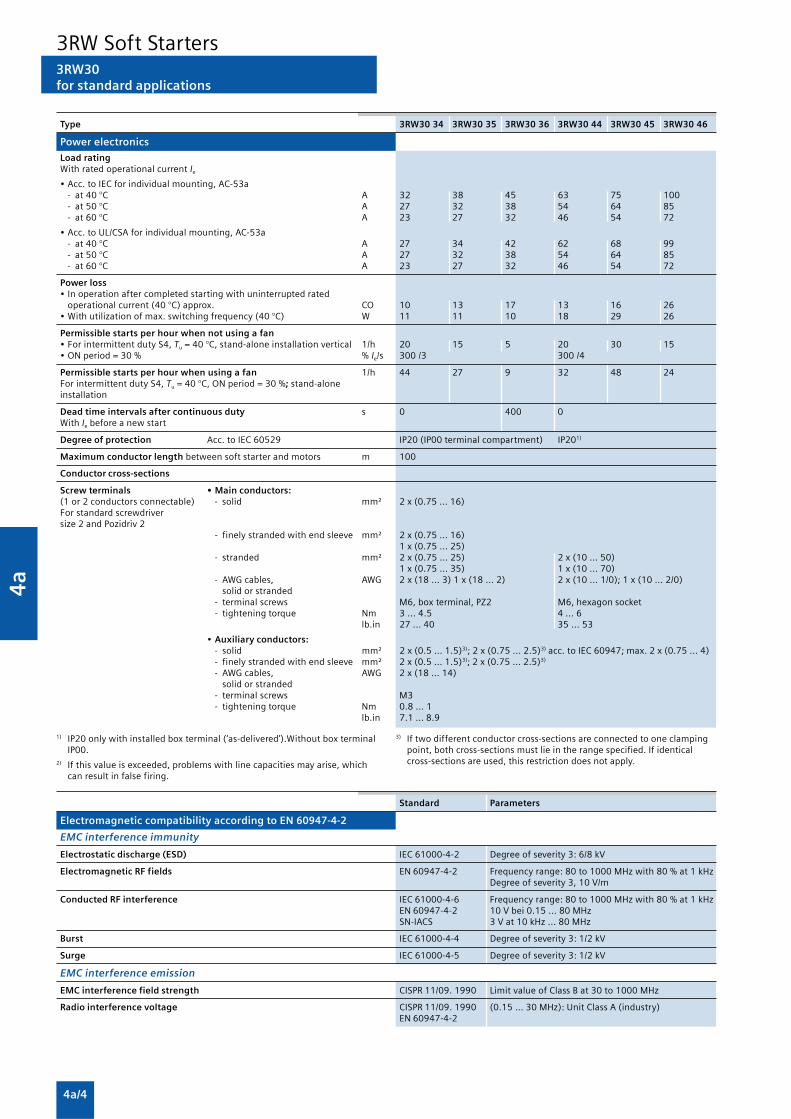
4a
4a/4
3RW30for standard applications
1) IP20 only with installed box terminal (‘as-delivered’).Without box terminalIP00.
2) If this value is exceeded, problems with line capacities may arise, whichcan result in false firing.
3) If two different conductor cross-sections are connected to one clampingpoint, both cross-sections must lie in the range specified. If identicalcross-sections are used, this restriction does not apply.
Type 3RW30 34 3RW30 35 3RW30 36 3RW30 44 3RW30 45 3RW30 46
Power electronics
Load ratingWith rated operational current Ie
• Acc. to IEC for individual mounting, AC-53a- at 40 °C A 32 38 45 63 75 100- at 50 °C A 27 32 38 54 64 85- at 60 °C A 23 27 32 46 54 72
• Acc. to UL/CSA for individual mounting, AC-53a- at 40 °C A 27 34 42 62 68 99- at 50 °C A 27 32 38 54 64 85- at 60 °C A 23 27 32 46 54 72
Power loss• In operation after completed starting with uninterrupted rated
operational current (40 °C) approx. CO 10 13 17 13 16 26• With utilization of max. switching frequency (40 °C) W 11 11 10 18 29 26
Permissible starts per hour when not using a fan• For intermittent duty S4, Tu = 40 °C, stand-alone installation vertical 1/h 20 15 5 20 30 15• ON period = 30 % % Ie/s 300 /3 300 /4
Permissible starts per hour when using a fan 1/h 44 27 9 32 48 24For intermittent duty S4, Tu = 40 °C, ON period = 30 %; stand-aloneinstallation
Dead time intervals after continuous duty s 0 400 0With Ie before a new start
Degree of protection Acc. to IEC 60529 IP20 (IP00 terminal compartment) IP201)
Maximum conductor length between soft starter and motors m 100
Conductor cross-sections
Screw terminals • Main conductors:(1 or 2 conductors connectable) - solid mm² 2 x (0.75 ... 16)For standard screwdriversize 2 and Pozidriv 2
- finely stranded with end sleeve mm² 2 x (0.75 ... 16)1 x (0.75 ... 25)
- stranded mm² 2 x (0.75 ... 25) 2 x (10 ... 50)1 x (0.75 ... 35) 1 x (10 ... 70)
- AWG cables, AWG 2 x (18 ... 3) 1 x (18 ... 2) 2 x (10 ... 1/0); 1 x (10 ... 2/0)solid or stranded
- terminal screws M6, box terminal, PZ2 M6, hexagon socket- tightening torque Nm 3 ... 4.5 4 ... 6
lb.in 27 ... 40 35 ... 53
• Auxiliary conductors:- solid mm² 2 x (0.5 ... 1.5)3); 2 x (0.75 ... 2.5)3) acc. to IEC 60947; max. 2 x (0.75 ... 4)- finely stranded with end sleeve mm² 2 x (0.5 ... 1.5)3); 2 x (0.75 ... 2.5)3)
- AWG cables, AWG 2 x (18 ... 14)solid or stranded
- terminal screws M3- tightening torque Nm 0.8 ... 1
lb.in 7.1 ... 8.9
Standard Parameters
Electromagnetic compatibility according to EN 60947-4-2
EMC interference immunity
Electrostatic discharge (ESD) IEC 61000-4-2 Degree of severity 3: 6/8 kV
Electromagnetic RF fields EN 60947-4-2 Frequency range: 80 to 1000 MHz with 80 % at 1 kHzDegree of severity 3, 10 V/m
Conducted RF interference IEC 61000-4-6 Frequency range: 80 to 1000 MHz with 80 % at 1 kHzEN 60947-4-2 10 V bei 0.15 ... 80 MHzSN-IACS 3 V at 10 kHz ... 80 MHz
Burst IEC 61000-4-4 Degree of severity 3: 1/2 kV
Surge IEC 61000-4-5 Degree of severity 3: 1/2 kV
EMC interference emission
EMC interference field strength CISPR 11/09. 1990 Limit value of Class B at 30 to 1000 MHz
Radio interference voltage CISPR 11/09. 1990 (0.15 ... 30 MHz): Unit Class A (industry)EN 60947-4-2
3RW Soft Starters

4a
4a/5
3RW30for standard applications
Characteristic curves
Permissible installation height
At an installation height above 2000 m, the max. permissibleoperational voltage is reduced to 460 V.
More information
Configuration
The 3RW solid-state motor controllers are designed for easystarting conditions. In the event of deviating conditions orincreased switching frequency, it may be necessary to choose alarger device. For accurate dimensioning, use the Win-SoftStarter selection and simulation program.
If necessary, an overload relay for heavy starting must beselected where long starting times are involved. PTC sensorsare recommended. This also applies for the smooth ramp-downbecause during the rampdown time an additional currentloading applies in contrast to free rampdown.
In the motor feeder between the SIRIUS 3RW soft starter andthe motor, no capacitive elements are permitted (e.g. noreactive-power compensation equipment). In addition, neitherstatic systems for reactive-power compensation nor dynamicPFC (Power Factor Correction) must be operated in parallelduring starting and ramp-down of the soft starter. This isimportant to prevent faults arising on the compensationequipment and/or the soft starter.
All elements of the main circuit (such as fuses, controls andoverload relays) should be dimensioned for direct starting,following the local short-circuit conditions. Fuses, controls andoverload relays must be ordered separately. Please observe themaximum switching frequencies specified in the technicalspecifications.
Note:When induction motors are switched on, voltage drops occuras a rule on starters of all types (direct starters, star-deltastarters, soft starters). The infeed transformer must always bedimensioned such that the voltage dip when starting themotor remains within the permissible tolerance. If the infeedtransformer is dimensioned with only a small margin, it is bestfor the control voltage to be supplied from a separate circuit(independently of the main voltage) in order to avoid thepotential switching off of the soft starter.
Power electronics circuit diagram1)
L1
NS
B0_
0041
0b
L2 L3
T1 T2 T3
1) Schematic circuit diagram applies to sizes S0 and S2;for size S00, phase L3 is bridged;for size S3, phase L2 is bridged.
Status graphs
Control with a PLC
When a 3RW30 is operated with a Triac output or thyristoroutput, the leakage current at the PLC output should be < 1 mAbecause otherwise the 3RW30 will interpret the resultantvoltage drop at the input as an “On command”. As a correctivemeasure for PLC outputs with a higher leakage current, an RCelement with > 100 nF and 220 W can be connected in seriesbetween “IN1” and terminal “A2” of the 3RW30.
Win-Soft Starter selection and simulation program
With this software, you can simulate and select all Siemens softstarters, taking into account various parameters such as mainsproperties, motor and load data, and special applicationrequirements.
The software is a valuable tool, which makes complicated,lengthy manual calculations for determining the required softstarters superfluous.
The Win-Soft Starter CD-ROM can be downloaded free ofcharge from
www.siemens.com/lowvoltage/demosoftware
You can find more information on the Internet at:http://www.siemens.com/softstarter
�
�
��
��
����� ������
��
�
�
�
� ���
����� ������
� ���
3RW30 – 3-phase motor
Auxiliary contacts(sizes S0 to S3 only)
3RW31
�
�
��
��
��� ���
���
�
��
3RW Soft Starters

4a
4a/6
3RW40for standard applications
Function
SIRIUS 3RW40 soft starters have all the same advantages as the3RW30/31 soft starters. At the same time they come withadditional functions and a two-phase control method (PolarityBalancing) that is unique in the performance range up to 250kW. Starting voltage, starting and ramp-down time of thevoltage ramp and current limit are all easy to set using steplessrotary potentiometers, the same as on the SIRIUS 3RW30/31.The rated motor current, the setting of the tripping time andthe resetting of the motor overload function are controlled likethe SIRIUS overload relays by means of potentiometers andkeys. Once again there is nothing new to get used to.
SIRIUS 3RW40 comes with the new, patented control methodcalled “Polarity Balancing”, which is designed to prevent directcurrent components in two-phase controlled soft starters. Ontwo-phase controlled soft starters the current resulting fromsuperimposition of the two controlled phases flows in theuncontrolled phase. This results for physical reasons in anasymmetric distribution of the three phase currents during thestarting operation of the motor. This phenomenon cannot beinfluenced, but in most applications it is non-critical.Controlling the power semiconductors in the two controlledphases results not only in this asymmetry, however, but also inthe previously mentioned direct current components which cancause severe noise generation on the motor at startingvoltages of less than 50 %. “Polarity Balancing” reliablyeliminates these direct current components during the ramp-up phase. It creates a motor ramp-up that is uniform in speed,torque and current rise. At the same time the acoustic qualityof the starting operation comes close to the quality of a three-phase controlled starting operation. This is made possible bythe on-going dynamic balancing of current half-waves ofdifferent polarity during the motor ramp-up.
The SIRIUS 3RW40 is equipped with optimum functionality. Anintegral bypass contact system reduces the power loss of thesoft starter during operation. This reliably prevents heating ofthe switchgear environment. Using a 4-step rotarypotentiometer it is possible to set different overload trippingtimes. Thanks to the integral motor overload protection to IEC60947-4-2 there is no need of an additional overload relay.Device variants with integrated thermistor motor protection(PTC type A of Thermoclick) are available as an option for thesizes S0 to S3. This saves space in the control cabinet andwiring outlay in the feeder. Internal intrinsic device protectionprevents in addition the thermal overloading of the thyristorsand the power section defects this can cause.
As an option the thyristors can also be protected by SITORsemiconductor fuses from short-circuiting so that the softstarter is still functional after a short-circuit (coordination type2). And even inrush current peaks are reliably avoided thanksto adjustable current limiting. Three LEDs are used to indicatethe operating state as well as possible errors, e.g. non-permissible tripping time (CLASS setting), mains or phasefailure, missing load, thermal overloading or device faults.
We offer a comprehensive range of accessories for our softstarters. Examples include box terminal blocks, accessories formechanical reset and a module for remote reset (size S6 orlarger) or a sealing cover or easy-to-fit terminal covers foroptimum touch protection.
• Soft starting with voltage ramp; the starting voltage settingrange Us is 40 to 100 % and the ramp time tR can be set from0 to 20 s.
• Smooth ramp-down with voltage ramp; the running downtime toff can be set between 0 s to 20 s. The switch-offvoltage Uoff is then dependent on the selected startingvoltage Us.
• Solid-state motor overload and intrinsic device protection
• Optional thermistor motor protection (up to size S3)
• Remote reset (integrated up to size S3, optional for size S6and larger)
• Adjustable current limiting
• Integrated bypass contact system to minimize power loss
• Setting with potentiometers
• Simple mounting and commissioning
• Integrated status monitoring and fault monitoring
• Mains voltages 50/60 Hz, 200 to 600 V
• Various control voltage versions- sizes S0 to S3:
24 VAC/DC and110 ... 230 VAC/DC
- sizes S6 to S12:115 VAC and 230 VAC.Control by way of the internal 24 V DC supply and directcontrol by means of PLC possible.
• Wide temperature range from -25 to +60 °C
• Built-in auxiliary contacts ensure user-friendly control andpossible further processing within the system
3RW Soft Starters

4a
4a/7
3RW40for standard applications
Technical specifications
Type 3RW40 2. 3RW40 3., 3RW40 4.
Control electronics
Rated values TerminalRated control supply voltage A1/A2 V 24 110 ... 230 24 110 ... 230• Tolerance % ±20 -15/+10 ±20 -15/+10Rated control supply current• STANDBY mA < 150 < 50 < 200 < 50• During pick-up mA < 200 < 100 < 5000 < 1500• ON without fan mA < 250 < 50 < 200 < 50• ON with fan mA < 300 < 70 < 250 < 70Rated frequency Hz 50/60• Tolerance % ±10Control inputsIN ON/OFFRated operational current• AC mA Approx. 12 3/6 Approx. 12 3/6• DC mA Approx. 12 1.5/3 Approx. 12 1.5/3Relay outputsOutput 1 ON/RUN mode1) 13/14 Operating indication (NO)Output 2 BYPASSED 23/24 Bypass indication (NO)Output 3 OVERLOAD/FAILURE 95/96/98 Overload/error indication (NC/NO)Rated operational current A 3 AC-15/AC-14 at 230 V,
A 1 DC-13 at 24 VProtection against overvoltages Protection by means of varistor through contactShort-circuit protection 4 A gL/gG operational class;
6 A quick (fuse is not included in scope of supply)
1) Factory default: ON mode.
Type 3RW40 5. 3RW40 7 .
Control electronics
Rated values TerminalRated control supply voltage A1/A2 VAC 115 230 115 230• Tolerance % -15/+10 -15/+10Rated control supply current STANDBY mA 15 15Rated control supply current ON1) mA 440 200 660 360Rated frequency Hz 50/60 50/60• Tolerance % ±10 ±10Control inputsIN ON/OFFRated operational current mA Approx. 10 acc. to DIN 19240Rated operational voltage V DC 24 from internal supply dc+ or
external DC supply (acc. to DIN 19240) through terminals and INRelay outputsOutput 1 ON/RUN mode2) 13/14 Operating indication (NO)Output 2 BYPASSED 23/24 Bypass indication (NO)Output 3 OVERLOAD/FAILURE 95/96/98 Overload/error indication (NC/NO)Rated operational current A 3 AC-15/AC-14 at 230 V,
A 1 DC-13 at 24 VProtection against overvoltages Protection by means of varistor through contactShort-circuit protection 4 A gL/gG operational class;
6 A quick (fuse is not included in scope of supply)
1) Values for the coil power consumption at +10 % Un, 50 Hz. 2) Factory default: ON mode.
Type 3RW40 2., 3RW40 3., 3RW40 4.
Control electronics
Operating indications LED DEVICE STATE/BYPASSED/FAILURE OVERLOADOff Green Off OffStart Green Green flashing OffBypass Green Green OffRamp-down Green Green flashing OffAlarm signalsIe/class setting not permissible Green Not relevant Red flashingStart inhibited/thyristors too hot Yellow flashing Not relevant OffError signals• 24V: U < 0.75 x Us or U > 1.25 x Us Off Red Off• 110 ... 230 V: U < 0.75 x Us or U > 1.15 x Us Off Red OffNon-permissible Ie/Class settingfor edge 0 –> 1 on input IN Green Red Red flashingMotor protection shut-down Green Off RedThermistor motor protection disconnection Green Off Red flickeringThermal overloading of the thyristors Yellow Red OffMissing mains voltage, phase failure, missing load Green Red OffDevice fault Red Red Off
3RW Soft Starters
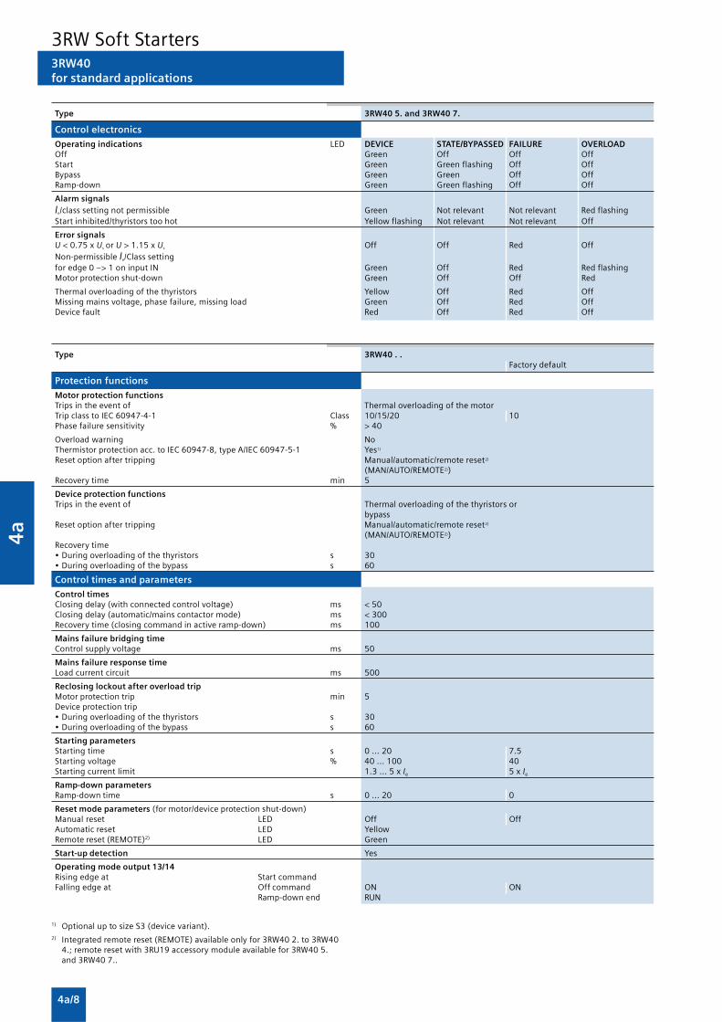
4a
4a/8
1) Optional up to size S3 (device variant).2) Integrated remote reset (REMOTE) available only for 3RW40 2. to 3RW40
4.; remote reset with 3RU19 accessory module available for 3RW40 5.and 3RW40 7..
3RW40for standard applications
Type 3RW40 5. and 3RW40 7.
Control electronics
Operating indications LED DEVICE STATE/BYPASSED FAILURE OVERLOADOff Green Off Off OffStart Green Green flashing Off OffBypass Green Green Off OffRamp-down Green Green flashing Off Off
Alarm signalsIe/class setting not permissible Green Not relevant Not relevant Red flashingStart inhibited/thyristors too hot Yellow flashing Not relevant Not relevant Off
Error signalsU < 0.75 x Us or U > 1.15 x Us Off Off Red OffNon-permissible Ie/Class settingfor edge 0 –> 1 on input IN Green Off Red Red flashingMotor protection shut-down Green Off Off Red
Thermal overloading of the thyristors Yellow Off Red OffMissing mains voltage, phase failure, missing load Green Off Red OffDevice fault Red Off Red Off
Type 3RW40 . .Factory default
Protection functions
Motor protection functionsTrips in the event of Thermal overloading of the motorTrip class to IEC 60947-4-1 Class 10/15/20 10Phase failure sensitivity % > 40
Overload warning NoThermistor protection acc. to IEC 60947-8, type A/IEC 60947-5-1 Yes1)
Reset option after tripping Manual/automatic/remote reset2)
(MAN/AUTO/REMOTE2))Recovery time min 5
Device protection functionsTrips in the event of Thermal overloading of the thyristors or
bypassReset option after tripping Manual/automatic/remote reset2)
(MAN/AUTO/REMOTE2))Recovery time• During overloading of the thyristors s 30• During overloading of the bypass s 60
Control times and parameters
Control timesClosing delay (with connected control voltage) ms < 50Closing delay (automatic/mains contactor mode) ms < 300Recovery time (closing command in active ramp-down) ms 100
Mains failure bridging timeControl supply voltage ms 50
Mains failure response timeLoad current circuit ms 500
Reclosing lockout after overload tripMotor protection trip min 5Device protection trip• During overloading of the thyristors s 30• During overloading of the bypass s 60
Starting parametersStarting time s 0 ... 20 7.5Starting voltage % 40 ... 100 40Starting current limit 1.3 ... 5 x Ie 5 x Ie
Ramp-down parametersRamp-down time s 0 ... 20 0
Reset mode parameters (for motor/device protection shut-down)Manual reset LED Off OffAutomatic reset LED YellowRemote reset (REMOTE)2) LED Green
Start-up detection Yes
Operating mode output 13/14Rising edge at Start commandFalling edge at Off command ON ON
Ramp-down end RUN
3RW Soft Starters

4a
4a/9
3RW40for standard applications
1) Measurement at 60 °C according to UL/CSA not required.2) Current limit on soft starter set to 300 % IM.3) For intermittent duty S4 with ON period = 30 %, Tu = 40 °C, stand-alone
installation vertical. The quoted switching frequencies do not apply forautomatic mode.
4) Maximum adjustable rated motor current IM, dependent on CLASSsetting.
Type 3RW40 24 3RW40 26 3RW40 27 3RW40 28
Power electronics
Load rating with rated operational current Ie
• Acc. to IEC and UL/CSA1), for individual mounting, AC-53a- at 40 °C A 12.5 25.3 32.2 38- at 50 °C A 11 23 29 34- at 60 °C A 10 21 26 31
Smallest adjustable rated motor current IM
For the motor overload protection A 5 10 17 23
Power loss• In operation after completed starting with uninterrupted rated W 2 8 13 19
operational current (40 °C) approx.• During starting with current limit set to W 17 47 55 64
300 % IM (40°C)
Permissible rated motor current and starts per hour
• For normal starting (Class 10)- rated motor current IM
2), starting time 3 s A 12.5 25 32 38- starts per hour3) 1/h 50 23 23 19
- rated motor current IM2)4), starting time 4 s A 12.5 25 32 38
- starts per hour3) 1/h 36 15 16 12
• For heavy starting (Class 15)- rated motor current IM
2), starting time 4.5 s A 11 23 30 34- starts per hour3) 1/h 49 21 18 18
- rated motor current IM2)4), starting time 6 s A 11 23 30 34
- starts per hour3) 1/h 36 14 13 13
• For heavy starting (Class 20)- rated motor current IM
2), starting time 6 s A 10 21 27 31- starts per hour3) 1/h 47 21 20 18
- rated motor current IM2)4), starting time 8 s A 10 21 27 31
- starts per hour3) 1/h 34 15 14 13
Type 3RW40 2.-. .B.4, 3RW40 2.-. .B.5, 3RW40 5.-.BB.4, 3RW40 5.-.BB.5,3RW40 3.-. .B.4, 3RW40 3.-. .B.5, 3RW40 7.-.BB.4 3RW40 7.-.BB.53RW40 4.-. .B.4 3RW40 4.-. .B.5
Power electronics
Rated operational voltage VAC 200 ... 480 400 ... 600 200 ... 460 400 ... 600Tolerance % -15/+10 -15/+10 -15/+10 -15/+10
Rated frequency Hz 50/60Tolerance % ±10
Continuous duty at 40 °C (% of Ie) % 115
Minimum load (% of set motor current IM) % 20 15
Maximum cable length between soft starter and motor m 300
Permissible installation height m 5000(derating from 1000, see characteristic curves); higher on request
Permissible mounting position
• With auxiliary fan (for 3RW40 2. ... 3RW40 4.)
��������� � � � �
� �
• Without auxiliary fan (for 3RW40 2. ... 3RW40 4.)
NS
B0_
0189
7
10° 10°10°10° — (fan integrated in the soft starter)
Permissible ambient temperatureOperation °C -25 ... +60; (derating from +40)Storage °C -40 ... +80
Degree of protection IP20 for 3RW40 2.; IP00IP00 for 3RW40 3. and 3RW40 4.
3RW Soft Starters

4a
4a/10
3RW40for standard applications
1) Measurement at 60 °C according to UL/CSA not required.2) Current limit on soft starter set to 300 % IM.3) For intermittent duty S4 with ON period = 30 %, Tu = 40 °C, stand-alone
installation vertical. The quoted switching frequencies do not apply forautomatic mode.
4) Maximum adjustable rated motor current IM, dependent on CLASS setting.
1) Measurement at 60 °C according to UL/CSA not required.2) Current limit on soft starter set to 350 % IM.3) For intermittent duty S4 with ON period = 70 %, Tu = 40 °C, stand-alone
installation vertical. The quoted switching frequencies do not apply forautomatic mode.
4) Maximum adjustable rated motor current IM, dependent on CLASS setting.
Type 3RW40 36 3RW40 37 3RW40 38 3RW40 46 3RW40 47
Power electronics
Load rating with rated operational current Ie
• Acc. to IEC and UL/CSA1), for individual mounting, AC-53a- at 40 °C A 45 63 72 80 106- at 50 °C A 42 58 62,1 73 98- at 60 °C A 39 53 60 66 90
Smallest adjustable rated motor current IM
For the motor overload protection A 23 26 35 43 46
Power loss• In operation after completed starting with uninterrupted rated W 6 12 15 12 21
operational current (40 °C) approx.• During starting with current limit set to 300 % IM (40°C) W 79 111 125 144 192
Permissible rated motor current and starts per hour
• For normal starting (Class 10)- rated motor current IM
2), starting time 3 s A 45 63 72 80 106- starts per hour3) 1/h 38 23 22 22 15
- rated motor current IM2)4), starting time 4 s A 45 63 72 80 106
- starts per hour3) 1/h 26 15 15 15 10
• For heavy starting (Class 15)- rated motor current IM
2), starting time 4.5 s A 42 50 56 70 84- starts per hour3) 1/h 30 34 34 24 23
- rated motor current IM2)4), starting time 6 s A 42 50 56 70 84
- starts per hour3) 1/h 21 24 24 16 17
• For heavy starting (Class 20)- rated motor current IM
2), starting time 6 s A 38 46 50 64 77- starts per hour3) 1/h 30 31 34 23 23
- rated motor current IM2)4), starting time 8 s A 38 46 50 64 77
- starts per hour3) 1/h 21 22 24 16 16
Type 3RW40 55 3RW40 56 3RW40 73 3RW40 74 3RW40 75 3RW40 76
Power electronics
Load rating with rated operational current Ie
• Acc. to IEC and UL/CSA1), for individual mounting, AC-53a- at 40 °C A 134 162 230 280 356 432- at 50 °C A 117 145 205 248 315 385- at 60 °C A 100 125 180 215 280 335
Smallest adjustable rated motor current IM
For the motor overload protection A 59 87 80 130 131 207
Power loss• In operation after completed starting with uninterrupted rated W 60 75 75 90 125 165
operational current (40 °C) approx.• During starting with current limit set to 350 %2) IM (40°C) W 1043 1355 2448 3257 3277 3600
Permissible rated motor current and starts per hour
• For normal starting (Class 10)- rated motor current IM
2), starting time 10 s A 134 162 230 280 356 432- starts per hour3) 1/h 20 8 14 20 16 17
- rated motor current IM2)4), starting time 20 s A 134 162 230 280 356 432
- starts per hour3) 1/h 7 1.4 3 8 5 5
• For heavy starting (Class 15)- rated motor current IM
2), starting time 15 s A 134 152 210 250 341 402- starts per hour3) 1/h 11 8 11 13 11 12
- rated motor current IM2)4), starting time 30 s A 134 152 210 250 341 402
- starts per hour3) 1/h 1.2 1.7 1 6 2 2
• For heavy starting (Class 20)- rated motor current IM
2), starting time 20 s A 124 142 200 230 311 372- starts per hour3) 1/h 12 9 10 10 10 10
- rated motor current IM2)4), starting time 40 s A 124 142 200 230 311 372
- starts per hour3) 1/h 2 2 1 5 1 1
3RW Soft Starters

4a
4a/11
3RW40for standard applications
Soft starters Type 3RW40 2. 3RW40 3. 3RW40 4.
Conductor cross-sections
Both clamping points • Solid mm2 2 x (1.5 ... 2.5); 2 x (1.5 ... 16) 2 x (2.5 ... 16)connected 2 x (2.5 ... 6) acc. to
IEC 60947;max. 1 x 10
• With end sleeve mm2 2 x (1.5 ... 2.5); 2 x (1.5 ... 16) 2 x (2.5 ... 35)2 x (2.5 ... 6)
• Stranded mm2 — 2 x (1.5 ... 25) 2 x (10 ... 50)
• AWG cables
- solid or stranded (finely stranded) AWG 2 x (14 ... 10) 2 x (16 ... 2) 1 x (10 ... 2/0)
- stranded AWG 1 x 8 — —
• Tightening torque Nm 2 ... 2.5 4.5 6.5lb.in 18 ... 22 40 58
Tools PZ 2 PZ 2 Allen screw 4 mm
Degree of protection IP20 IP20 IP20(IP00 terminal (IP00 terminalcompartment) compartment)
Busbar connections Main conductor
• With cable lug acc. to DIN 46234 ormax. 20 mm wide
- stranded mm2 — 2 x (10 ... 70)
- finely stranded mm2 — 2 x (10 ... 50)
• AWG cables, solid or stranded AWG — 2 x (7 ... 1/0)
��������
3RW Soft Starters

4a
4a/12
Soft starters Type 3RW40 5. 3RW40 7.
Conductor cross-sections
Both clamping points • Finely stranded with end sleeve mm2 Max. 1 x 50, 1 x 70 Min. 2 x 50; max. 2 x 185connected • Finely stranded without end sleeve mm2 Max. 1 x 50, 1 x 70 Min. 2 x 50; max. 2 x 185
• Stranded mm2 Max. 2 x 70 Max. 2 x 70; max. 2 x 240
• Ribbon cable conductors mm Max. 2 x (6 x 15.5 x 0.8) Max. 2 x (20 x 24 x 0.5)(number x width x thickness)
• AWG cables, solid or stranded AWG Max. 2 x 1/0 Min. 2 x 2/0 Max. 2 x 500 kcmil
• Terminal screws M10 (hexagon socket, A/F4) M12 (hexagon socket, A/F5)- tightening torque Nm 10 ... 12 20 ... 22
lb.in 90 ... 110 180 ... 195
Screw terminals Main conductors:
Without box terminal/busbar connection
• Finely stranded with cable lug mm2 16 ... 951) 50 ... 2402)
• Stranded with cable lug mm2 25 ... 1201) 70 ... 2402)
• AWG cables, solid or stranded AWG 4 ... 250 kcmil 2/0 ... 500 kcmil
• Connecting bar (max. width) mm 17 25• Terminal screws M8 x 25 (A/F13) M10 x 30 (A/F17)
- tightening torque Nm 10 ... 14 14 ... 24lb.in 89 ... 124 124 ... 210
��������
3RW40for standard applications
1) When connecting cable lugs to DIN 46235, use 3RT19 56-4EA1 terminalcover for conductor cross-sections from 95 mm² to ensure phase spacing.
2) When connecting cable lugs to DIN 46234, the 3RT19 66-4EA1 terminalcover must be used for conductor cross-sections of 240 mm² and more aswell as DIN 46235 for conductor cross-sections of 185 mm² and more tokeep the phase clearance.
Soft starters Type 3RW40 . .
Conductor cross-sections
Auxiliary conductors (1 or 2 conductors can be connected):
Screw terminals
• Solid mm2 2 x (0.5 ... 2.5)• Finely stranded with end sleeve mm2 2 x (0.5 ... 1.5)
• AWG cables- solid or stranded AWG 2 x (20 ... 14)- finely stranded with end sleeve AWG 2 x (20 ... 16)
• Terminal screws- tightening torque Nm 0,8 ... 1.2
lb.in 7 ... 10.3
3RW Soft Starters

4a
4a/13
3RW40for standard applications
Standard Parameters
Electromagnetic compatibility acc. to EN 60947-4-2
EMC interference immunity
Electrostatic discharge (ESD) EN 61000-4-2 ±4 kV contact discharge, ±8 kV air discharge
Electromagnetic RF fields EN 61000-4-3 Frequency range: 80 ... 1000 MHz with 80 % at 1 kHzDegree of severity 3: 10 V/m
Conducted RF interference EN 61000-4-6 Frequency range: 150 kHz ... 80 MHz with 80 % at 1 kHzInterference 10 V
RF voltages and RF currents on cables
• Burst EN 61000-4-4 ±2 kV/5 kHz
• Surge EN 61000-4-5 ±1 kV line to line±2 kV line to earth
EMC interference emission
EMC interference field strength EN 55011 Limit value of Class A at 30 ... 1000 MHz,limit value of Class B with 3RW40 2. 24 VAC/DC
Radio interference voltage EN 55011 Limit value of Class A at 0.15 ... 30 MHz,limit value of Class B with 3RW40 2. 24 VAC/DC
Is an RI suppression filter necessary?
Degree of noise suppression A (industrial applications) No
Degree of noise suppression B(applications for residential areas)Control voltage• 230 V AC/DC Not available1)
• 24V AC/DC No for 3RW40 2.;yes for 3RW40 3. and 3RW40 4.
1) Degree of noise suppression B cannot be obtained through the use offilters as the strength of the electromagnetic field is not attenuated bythe filter.
3RW Soft Starters
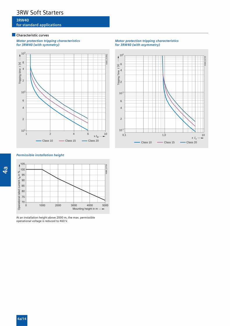
4a
4a/14
Characteristic curves
Motor protection tripping characteristicsfor 3RW40 (with symmetry)
Permissible installation height
At an installation height above 2000 m, the max. permissibleoperational voltage is reduced to 460 V.
Motor protection tripping characteristicsfor 3RW40 (with asymmetry)
101
102
103
2
4
6
2
4
6
ex2 4 6 10
NS
B0_
0148
8a
1
Class 10 Class 15 Class 20
[s]
Trip
ping
tim
e
10 1
10 2
103
2
4
6
2
4
6
ex1,0 10
NS
B0_
0170
5
0,1
Class 10 Class 15 Class 20
[s]
Trip
ping
Tim
e
3RW40for standard applications
3RW Soft Starters

4a
4a/15
More information
Note:
These tables present sample set values and device sizes. Theyare intended only for the purposes of information and are notbinding. The set values depend on the application in questionand must be optimized during commissioning.
The soft starter dimensions should be checked wherenecessary with the Win-Soft Starter software or with the helpof Technical Assistance.
Application examples for normal starting (Class 10)
Normal starting Class 10 (up to 20 s with 350 % In motor),The soft starter rating can be selected to be as high as the rating of the motor used.
Application Conveyor belt Roller conveyor Compressor Small fan Pump Hydraulic pump
Starting parameters
• Voltage ramp and currentlimiting- starting voltage % 70 60 50 40 40 40- starting time s 10 10 10 10 10 10- current limit value 5 x IM 5 x IM 4 x IM 4 x IM 4 x IM 4 x IM
Ramp-down time s 5 5 0 0 10 0
Application examples for heavy starting (Class 20)
Heavy starting Class 20 (up to 40 s with 350 % In motor),The soft starter has to be selected at least one rating class higher than the motor used.
Application Stirrer Centrifuge
Starting parameters
• Voltage ramp and currentlimiting- starting voltage % 40 40- starting time s 20 20- current limit value 4 x IM 4 x IM
Ramp-down time 0 0
3RW40for standard applications
3RW Soft Starters

4a
4a/16
Function
3RW44for High-Feature applications
Equipped with modern, ergonomic user prompting the SIRIUS3RW44 soft starters can be commissioned quickly and easilyusing a keypad and a menu-prompted, multi-line graphicdisplay with background lighting. The optimized motor ramp-up and ramp-down can be effected quickly, easily and reliablyby means of just a few settings with a selectable language.Four-key operation and plain-text displays for each menu pointguarantee full clarity at every moment of the parameterizationand operation. During operation and when control voltage isapplied, the display field continuously presents measuredvalues and operating values as well as warnings and faultmessages. An external display and operator module can beconnected by means of a connection cable to the soft starter,thus enabling active indications and the like to be read directlyfrom the control cabinet door.
The SIRIUS 3RW44 soft starters are equipped with optimumfunctionality. An integral bypass contact system reduces thepower loss of the soft starter during operation.
This reliably prevents heating of the switchgear environment.The SIRIUS 3RW44 soft starters have internal intrinsic deviceprotection. This prevents thermal overloading of the powersection’s thyristors, e.g. due to unacceptably high closingoperations.
Wiring outlay for installing an additional motor overload relay isno longer needed as the SIRIUS 3RW44 soft starters performthis function too. In addition they offer adjustable trip classesand a thermistor motor protection function. As an option thethyristors can also be protected by SITOR semiconductor fusesfrom short-circuiting so that the soft starter is still functionalafter a short-circuit (coordination type 2). And even inrushcurrent peaks are reliably avoided thanks to adjustable currentlimiting.
As a further option the SIRIUS 3RW44 soft starters can beupgraded with a PROFIBUS DP module. Thanks to theircommunication capability and their programmable controlinputs and relay outputs the SIRIUS 3RW44 soft starters can bevery easily and quickly integrated in higher-level controllers.
In addition a creep speed function is available for positioningand setting jobs. With this function the motor can be controlledin both directions of rotation with reduced torque and anadjustable, low speed.
On the other hand the SIRIUS 3RW44 soft starters offer a new,combined DC braking function for the fast stopping of drivingloads.
Highlights
• Soft starting with breakaway pulse, torque control or voltageramp, adjustable torque or current limiting as well as anycombination of these, depending on load type
• Integrated bypass contact system to minimize power loss
• Various setting options for the starting parameters such asstarting torque, starting voltage, ramp-up and ramp-downtime, and much more in three separate parameter sets
• Start-up detection
• Inside-delta circuit for savings in terms of size and equipmentcosts
• Various ramp-down modes selectable: free ramp-down,torque-controlled pump ramp-down, combined DC braking
• Solid-state motor overload and intrinsic device protection
• Thermistor motor protection
• Keypad with a menu-prompted, multi-line graphic displaywith background lighting
• Interface for communication with the PC for more accuratesetting of the parameters as well as for control andmonitoring
• Simple adaptation to the motor feeder
• Simple mounting and commissioning
• Display of operating states and fault messages
• Connection to PROFIBUS with optional PROFIBUS DP module
• External display and operator module
• Mains voltages from 200 to 690 V, 50 to 60 Hz
• Applicable up to 60 °C (derating from 40 °C)
3RW Soft Starters

4a
4a/17
3RW44for High-Feature applications
Technical specifications
Type 3RW44 . .-.BC3. 3RW44 . .-.BC4.Terminal
Control electronics
Rated valuesRated control supply voltage A1/A2/PE V 115 AC 230 AC• Tolerance % -15/+10 -15/+10Rated control supply current STANDBY mA 30 20
Rated control supply current ON• 3RW44 2. mA 300 170• 3RW44 3. mA 500 250• 3RW44 4. mA 750 400
• 3RW44 5. mA 450 200• 3RW44 6. mA 650 300
Maximum current (pickup bypass)• 3RW44 2. mA 1000 500• 3RW44 3. mA 2500 1250• 3RW44 4. mA 6000 3000
• 3RW44 5. mA 4500 2500• 3RW44 6. mA 4500 2500
Rated frequency Hz 50 ... 60 50 ... 60• Tolerance % ±10 ±10
Type 3RW44 . .Terminal Factory default
Control electronics
Control inputsInput 1 IN1 Start motor right parameter set 1Input 2 IN2 No actionInput 3 IN3 No actionInput 4 IN4 Trip reset
Supply L+/L-• Rated operational current mA Approx. 10 per input to DIN 19240• Rated operational voltage L+ Internal voltage: 24 V DC from
internal supply through terminal L+to IN1 ... IN4. Maximum load at L+approx. 55 mA
L- External voltage: DC external voltage(acc. to DIN 19240) throughterminals L- and IN1 ... IN4(min. 12 V DC, max. 30 V DC)
Thermistor motor protection inputInput T1/T2 PTC type A or Thermoclick Deactivated
Relay outputs (floating auxiliary contacts)Output 1 13/14 ON periodOutput 2 23/24 No actionOutput 3 33/34 No actionOutput 4 95/96/98 Group fault
Switching capacity of the relay outputs (auxiliary contacts)230 V/AC-15 A 3 at 240 V24 V/DC-13 A 1 at 24 VProtection against overvoltages Protection by means of varistor through relay contactShort-circuit protection 4 A gL/gG operational class;
6 A quick (fuse is not included in scope of supply)
Protection functions
Motor protection functionsTrips in the event of Thermal overloading of the motorTrip class to IEC 60947-4-1 Class 5/10/15/20/30 10Phase failure sensitivity % >40
Overload warning YesReset and recovery Manual/Automatic ManualReset option after tripping Manual/Automatic ManualRecovery time min. 1 ... 30 1
Device protection functionsTrips in the event of Thermal overloading of the thyristorsReset option after tripping Manual/Automatic ManualRecovery time min. 0.5
Bypass protection functionsTrips in the event of Thermal overloading of the bypass
contactsReset option after tripping ManualRecovery time min. 1
3RW Soft Starters

4a
4a/18
3RW44for High-Feature applications
1) Max. current limit value for 3RW44 53 ... 3RW44 57: 500 % and for3RW44 58 ... 3RW44 66 :450 %.
2) Reference variable depends on the motor used but is always smaller thanthe rated torque of the motor.
Type 3RW44 . .Factory default
Control times and parametersControl timesClosing delay (with connected control voltage) ms <50Closing delay (automatic mode) ms <4000Recovery time (closing command in active ramp-down) ms <100Mains failure bridging timeControl supply voltage ms 100Mains failure response timeLoad current circuit ms 100Reclosing lockout after overload tripMotor protection trip min. 1 ... 30 1Device protection trip s 30Setting options for startingVoltage ramp for starting voltage % 20 ... 100 30Torque control for starting torque % 10 ... 100 10Torque control for limit torque % 20 ... 200 150Starting time s 0 ... 360 20Maximum starting time s 1 ... 1000 DeactivatedCurrent limit value % 125 ... 5501) 450Breakaway voltage % 40 ... 100 80Breakaway time s 0 ... 2 DeactivatedMotor heat output % 1 ... 100 20Creep mode Left/Right runningSpeed factor as function of rated speed (n = nrated/factor) 3 ... 21 7Creep torque2) % 20 ... 100 50Setting options for ramp-downTorque control for stopping torque % 10 ... 100 10Ramp-down time s 0 ... 360 10Dynamic braking torque % 20 ... 100 50DC braking torque % 20 ... 100 50Operating indications
Test voltageTest mains phasesReady to startStart activeMotor runningRamp-down activeEmergency start active
Warnings/error signalsMains voltage missingLeading-edge phase errorPhase failure• L1• L2• L3Missing load phase• T1• T2• T3Failure• Contact element 1 (thyristor)• Contact element 2 (thyristor)• Contact element 3 (thyristor)Flash memory faultySupply voltage• Below 75 %• Below 85 %• Over 110 %Current unbalance exceededThermal motor model overloadPrewarning limit exceeded• Motor heating• Time-related trip reserveBypass element defectiveMains voltage too highDevice not namedWrong naming versionCurrent measuring range exceededBypass element protection disconnectionPower section• Overheated• Overheating
3RW Soft Starters

4a
4a/19
3RW44for High-Feature applications
Type 3RW44 . .Factory default
Control times and parameters
Warnings/error signals (continued)Temperature sensor• Overload• Open circuit• Short-circuit
Ground fault• Detected
Connection abort in manual operating modeMax. number of starts exceededIe limit value overshoot/undershoot
Heat sink sensor• Open circuit• Short-circuit
Quick-stop activeSwitching block defectiveIe/class setting not permissible
No external start-up parameters receivedPAA fault
Control inputsInput 1 Motor right parameter set 1Input 2 No actionInput 3 No actionInput 4 Trip reset
Parameterizing options for control inputs 1 ... 4 No actionLocal manual modeEmergency startCreep speedQuick-stopTrip reset
Motor right parameter set 1Motor left parameter set 11)
Motor right parameter set 2Motor left parameter set 21)
Motor right parameter set 3Motor left parameter set 31)
Relay outputsOutput 1 ON periodOutput 2 No actionOutput 3 No actionOutput 4 Group fault
Parameterizing options for relay outputs 1 ... 3 No actionPAA output 1PAA output 2
Input 1Input 2Input 3Input 4
StartingOperation/BypassRamp-down
ON periodCommand motor onDC braking contactor
Group warningGroup faultBus faultDevice fault
Power onReady to start
Motor temperature sensor DeactivatedThermoclickPTC type A
1) Parameter motor left possible only in conjunction with creep mode.
3RW Soft Starters

4a
4a/20
Type 3RW44 . .-.BC.4 3RW44 . .-.BC.5 3RW44 . .-.BC.6
Power electronicsRated operational voltage for inline circuit VAC 200 ... 460 400 ... 600 400 ... 690Tolerance % -15/+10 -15/+10 -15/+10Rated operational voltage for inside-delta circuit VAC 200 ... 460 400 ... 600 400 ... 600Tolerance % -15/+10 -15/+10 -15/+10Rated frequency Hz 50 ... 60Tolerance % ±10Continuous duty at 40 °C (% of Ie) % 115Minimum load (% of set motor current IM) % 8Maximum cable length between soft starter and motor m 5001)
Permissible installation height m 5000 (derating from 1000, see characteristic curves); higher on request
Permissible mounting position
��������� � � � �
� �
Permissible ambient temperatureOperation °C 0 ... +60; (derating from +40)Storage °C -25 ... +80Degree of protection IP00
3RW44for High-Feature applications
1) At the project configuration stage, it is important to make allowance forthe voltage drop on the motor cable up to the motor connection. Ifnecessary, higher values for the rated operational voltage or currentmust be calculated accordingly for the soft starter.
1) Measurement at 60 °C according to UL/CSA not required.2) Current limit on soft starter set to 350 % IM.3) For intermittent duty S4 with ON period = 70 %, Tu = 40 °C, stand-alone
installation vertical. The quoted switching frequencies do not apply forautomatic mode.
4) Maximum adjustable rated motor current IM, dependent on CLASSsetting.
Type 3RW44 22 3RW44 23 3RW44 24 3RW44 25 3RW44 26 3RW44 27
Power electronicsRated operational current Ie 29 36 47 57 77 93Load rating with rated operational current Ie
• Acc. to IEC and UL/CSA1), for individual mounting, AC-53a- at 40 °C A 29 36 47 57 77 93- at 50 °C A 26 32 42 51 68 82- at 60 °C A 23 29 37 45 59 72
Smallest adjustable rated motor current IM A 5 7 9 11 15 18For the motor overload protectionPower loss• In operation after completed starting with uninterrupted rated
operational current (40 °C) approx. W 8 10 32 36 45 55• During starting with current limit set to 350 % IM (40 °C) W 400 470 600 725 940 1160Permissible rated motor current and starts per hour• Normal starting (Class 5)
- rated motor current IM2), starting time 5 s A 29 36 47 57 77 93
- starts per hour3) 1/h 41 34 41 41 41 41- rated motor current IM
2)4), starting time 10 s A 29 36 47 57 77 93- starts per hour3) 1/h 20 15 20 20 20 20
• Normal starting (Class 10)- rated motor current IM
2), starting time 10 s A 29 36 47 57 77 93- starts per hour3) 1/h 20 15 20 20 20 20- rated motor current IM
2)4), starting time 20 s A 29 36 47 57 77 93- starts per hour3) 1/h 10 6 10 10 8 8
• Normal starting (Class 15)- rated motor current IM
2), starting time 15 s A 29 36 47 57 77 93- starts per hour3) 1/h 13 9 13 13 13 13- rated motor current IM
2)4), starting time 30 s A 29 36 47 57 77 93- starts per hour3) 1/h 6 4 6 6 6 6
• For heavy starting (Class 20)- rated motor current IM
2), starting time 20 s A 29 36 47 57 73 88- starts per hour3) 1/h 10 6 10 10 10 10- rated motor current IM
2)4), starting time 40 s A 29 36 47 57 73 88- starts per hour3) 1/h 4 2 4 5 1.8 0.8
• For very heavy starting (Class 30)- rated motor current IM
2), starting time 30 s A 29 36 44 57 65 77- starts per hour3) 1/h 6 4 6 6 6 6- rated motor current IM
2)3), starting time 60 s A 29 36 44 57 65 77- starts per hour3) 1/h 1.8 0.8 3.3 1.5 2 1
3RW Soft Starters

4a
4a/21
3RW44for High-Feature applications
Type 3RW44 34 3RW44 35 3RW44 36
Power electronics
Rated operational current Ie 113 134 162
Load rating with rated operational current Ie
• Acc. to IEC and UL/CSA1), for individual mounting, AC-53a- at 40 °C A 113 134 162- at 50 °C A 100 117 145- at 60 °C A 88 100 125
Smallest adjustable rated motor current IM A 22 26 32For the motor overload protection
Power loss• In operation after completed starting with uninterrupted rated
operational current (40 °C) approx. CO 64 76 95• During starting with current limit set to 350 % IM (40 °C) W 1350 1700 2460
Permissible rated motor current and starts per hour
• Normal starting (Class 5)- rated motor current IM
2), starting time 5 s A 113 134 162- starts per hour3) 1/h 41 39 41
- rated motor current IM2)4), starting time 10 s A 113 134 162
- starts per hour3) 1/h 20 15 20
• Normal starting (Class 10)- rated motor current IM
2), starting time 10 s A 113 134 162- starts per hour3) 1/h 20 15 20
- rated motor current IM2)4), starting time 20 s A 113 134 162
- starts per hour3) 1/h 9 6 7
• Normal starting (Class 15)- rated motor current IM
2), starting time 15 s A 113 134 162- starts per hour3) 1/h 13 9 12
- rated motor current IM2)4), starting time 30 s A 113 134 162
- starts per hour3) 1/h 6 6 1
• For heavy starting (Class 20)- rated motor current IM
2), starting time 20 s A 106 125 147- starts per hour3) 1/h 9 9 10
- rated motor current IM2)4), starting time 40 s A 106 125 147
- starts per hour3) 1/h 1.5 2 1
• For very heavy starting (Class 30)- rated motor current IM
2), starting time 30 s A 91 110 120- starts per hour3) 1/h 6 6 6
- rated motor current IM2)4), starting time 60 s A 91 110 120
- starts per hour3) 1/h 2 2 2
1) Measurement at 60 °C according to UL/CSA not required.2) Current limit on soft starter set to 350 % IM.3) For intermittent duty S4 with ON period = 70 %, Tu = 40 °C, stand-alone
installation vertical. The quoted switching frequencies do not apply forautomatic mode.
4) Maximum adjustable rated motor current IM, dependent on CLASSsetting.
3RW Soft Starters

4a
4a/22
1) Measurement at 60 °C according to UL/CSA not required.2) Current limit on soft starter set to 350 % IM.3) For intermittent duty S4 with ON period = 70 %, Tu = 40 °C, stand-alone
installation vertical. The quoted switching frequencies do not apply forautomatic mode.
4) Maximum adjustable rated motor current IM, dependent on CLASSsetting.
Type 3RW44 43 3RW44 44 3RW44 45 3RW44 46 3RW44 47
Power electronics
Rated operational current Ie 203 250 313 356 432
Load rating with rated operational current Ie
• Acc. to IEC and UL/CSA1), for individual mounting, AC-53a- at 40 °C A 203 250 313 356 432- at 50 °C A 180 215 280 315 385- at 60 °C A 156 185 250 280 335
Smallest adjustable rated motor current IM A 40 50 62 71 86For the motor overload protection
Power loss• In operation after completed starting with uninterrupted rated
operational current (40 °C) approx. CO 89 110 145 174 232• During starting with current limit set to 350 % IM (40 °C) W 3350 4000 4470 5350 5860
Permissible rated motor current and starts per hour
• Normal starting (Class 5)- rated motor current IM
2), starting time 5 s A 203 250 313 356 432- starts per hour3) 1/h 41 41 41 41 39
- rated motor current IM2)4), starting time 10 s A 203 250 313 356 432
- starts per hour3) 1/h 20 20 19 17 16
• Normal starting (Class 10)- rated motor current IM
2), starting time 10 s A 203 250 313 356 432- starts per hour3) 1/h 20 20 19 17 16
- rated motor current IM2)4), starting time 20 s A 203 250 313 356 432
- starts per hour3) 1/h 9 10 6 4 5
• Normal starting (Class 15)- rated motor current IM
2), starting time 15 s A 203 240 313 325 402- starts per hour3) 1/h 13 13 10 13 11
- rated motor current IM2)4), starting time 30 s A 203 240 313 325 402
- starts per hour3) 1/h 3 6 1 2 1
• For heavy starting (Class 20)- rated motor current IM
2), starting time 20 s A 195 215 275 285 356- starts per hour3) 1/h 10 10 10 10 10
- rated motor current IM2)4), starting time 40 s A 195 215 275 285 356
- starts per hour3) 1/h 1 5 1 3 1
• For very heavy starting (Class 30)- rated motor current IM
2), starting time 30 s A 162 180 220 240 285- starts per hour3) 1/h 6 6 6 6 6
- rated motor current IM2)4), starting time 60 s A 162 180 220 240 285
- starts per hour3) 1/h 3 3 3 2 1
3RW44for High-Feature applications
3RW Soft Starters

4a
4a/23
Type 3RW44 53 3RW44 54 3RW44 55 3RW44 56 3RW44 57 3RW44 58
Power electronics
Rated operational current Ie 551 615 693 780 880 970
Load rating with rated operational current Ie
• Acc. to IEC and UL/CSA1), for individual mounting, AC-53a- at 40 °C A 551 615 693 780 880 970- at 50 °C A 494 551 615 693 780 850- at 60 °C A 438 489 551 615 693 760
Smallest adjustable rated motor current IM A 110 123 138 156 176 194For the motor overload protection
Power loss• In operation after completed starting with uninterrupted rated
operational current (40 °C) approx. CO 159 186 220 214 250 270• During starting with current limit set to 350 % IM (40 °C) W 7020 8100 9500 11100 13100 15000
Permissible rated motor current and starts per hour
• Normal starting (Class 5)- rated motor current IM
2), starting time 5 s A 551 615 693 780 880 970- starts per hour3) 1/h 41 41 37 33 22 17
- rated motor current IM2)4), starting time 10 s A 551 615 693 780 880 970
- starts per hour3) 1/h 20 20 16 13 8 5
• Normal starting (Class 10)- rated motor current IM
2), starting time 10 s A 551 615 693 780 880 970- starts per hour3) 1/h 20 20 16 13 8 5
- rated motor current IM2)4), starting time 20 s A 551 615 693 780 880 970
- starts per hour3) 1/h 10 9 6 4 0.3 0.3
• Normal starting (Class 15)- rated motor current IM
2), starting time 15 s A 551 615 666 723 780 821- starts per hour3) 1/h 13 13 11 9 8 8
- rated motor current IM2)4), starting time 30 s A 551 615 666 723 780 821
- starts per hour3) 1/h 6 4 3 1 0,4 0.5
• For heavy starting (Class 20)- rated motor current IM
2), starting time 20 s A 551 591 633 670 710 740- starts per hour3) 1/h 10 10 7 8 8 9
- rated motor current IM2)4), starting time 40 s A 551 591 633 670 710 740
- starts per hour3) 1/h 4 2 1 1 0,4 1
• For very heavy starting (Class 30)- rated motor current IM
2), starting time 30 s A 500 525 551 575 600 630- starts per hour3) 1/h 6 6 6 6 6 6
- rated motor current IM2)4), starting time 60 s A 500 525 551 575 600 630
- starts per hour3) 1/h 2 1 1 1 1.5 1
3RW44for High-Feature applications
1) Measurement at 60 °C according to UL/CSA not required.2) Current limit on soft starter set to 350 % IM.3) For intermittent duty S4 with ON period = 70 %, Tu = 40 °C, stand-alone
installation vertical. The quoted switching frequencies do not apply forautomatic mode.
4) Maximum adjustable rated motor current IM, dependent on CLASSsetting.
3RW Soft Starters

4a
4a/24
Type 3RW44 65 3RW44 66
Power electronics
Rated operational current Ie 1076 1214
Load rating with rated operational current Ie
• Acc. to IEC and UL/CSA1), for individual mounting, AC-53a- at 40 °C A 1076 1214- at 50 °C A 970 1076- at 60 °C A 880 970
Smallest adjustable rated motor current IM A 215 242For the motor overload protection
Power loss• In operation after completed starting with uninterrupted rated
operational current (40 °C) approx. CO 510 630• During starting with current limit set to 350 % IM (40 °C) W 15000 17500
Permissible rated motor current and starts per hour
• Normal starting (Class 5)- rated motor current IM
2), starting time 5 s A 1076 1214- starts per hour3) 1/h 30 20
- rated motor current IM2)4), starting time 10 s A 1076 1214
- starts per hour3) 1/h 10 6
• Normal starting (Class 10)- rated motor current IM
2), starting time 10 s A 1076 1214- starts per hour3) 1/h 11 6
- rated motor current IM2)4), starting time 20 s A 1076 1214
- starts per hour3) 1/h 3 0.5
• Normal starting (Class 15)- rated motor current IM
2), starting time 15 s A 1020 1090- starts per hour3) 1/h 7 5
- rated motor current IM2)4), starting time 30 s A 1020 1090
- starts per hour3) 1/h 1 1
• For heavy starting (Class 20)- rated motor current IM
2), starting time 20 s A 970 1030- starts per hour3) 1/h 7 5
- rated motor current IM2)4), starting time 40 s A 970 1030
- starts per hour3) 1/h 1 1
• For very heavy starting (Class 30)- rated motor current IM
2), starting time 30 s A 880 920- starts per hour3) 1/h 6 6
- rated motor current IM2)4), starting time 60 s A 880 920
- starts per hour3) 1/h 1 1
3RW44for High-Feature applications
1) Measurement at 60 °C according to UL/CSA not required.2) Current limit on soft starter set to 350 % IM.3) For intermittent duty S4 with ON period = 70 %, Tu = 40 °C, stand-alone
installation vertical. The quoted switching frequencies do not apply forautomatic mode.
4) Maximum adjustable rated motor current IM, dependent on CLASSsetting.
3RW Soft Starters
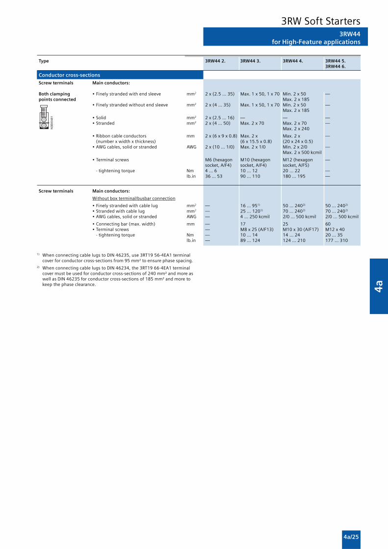
4a
4a/25
3RW44for High-Feature applications
1) When connecting cable lugs to DIN 46235, use 3RT19 56-4EA1 terminalcover for conductor cross-sections from 95 mm² to ensure phase spacing.
2) When connecting cable lugs to DIN 46234, the 3RT19 66-4EA1 terminalcover must be used for conductor cross-sections of 240 mm² and more aswell as DIN 46235 for conductor cross-sections of 185 mm² and more tokeep the phase clearance.
��������
Type 3RW44 2. 3RW44 3. 3RW44 4. 3RW44 5.3RW44 6.
Conductor cross-sections
Screw terminals Main conductors:
Both clamping • Finely stranded with end sleeve mm2 2 x (2.5 ... 35) Max. 1 x 50, 1 x 70 Min. 2 x 50 —points connected Max. 2 x 185
• Finely stranded without end sleeve mm2 2 x (4 ... 35) Max. 1 x 50, 1 x 70 Min. 2 x 50 —Max. 2 x 185
• Solid mm2 2 x (2.5 ... 16) — — —• Stranded mm2 2 x (4 ... 50) Max. 2 x 70 Max. 2 x 70 —
Max. 2 x 240
• Ribbon cable conductors mm 2 x (6 x 9 x 0.8) Max. 2 x Max. 2 x —(number x width x thickness) (6 x 15.5 x 0.8) (20 x 24 x 0.5)
• AWG cables, solid or stranded AWG 2 x (10 ... 1/0) Max. 2 x 1/0 Min. 2 x 2/0 —Max. 2 x 500 kcmil
• Terminal screws M6 (hexagon M10 (hexagon M12 (hexagon —socket, A/F4) socket, A/F4) socket, A/F5)
- tightening torque Nm 4 ... 6 10 ... 12 20 ... 22 —lb.in 36 ... 53 90 ... 110 180 ... 195 —
Screw terminals Main conductors:
Without box terminal/busbar connection
• Finely stranded with cable lug mm2 — 16 ... 951) 50 ... 2402) 50 ... 2402)
• Stranded with cable lug mm2 — 25 ... 1201) 70 ... 2402) 70 ... 2402)
• AWG cables, solid or stranded AWG — 4 ... 250 kcmil 2/0 ... 500 kcmil 2/0 ... 500 kcmil
• Connecting bar (max. width) mm — 17 25 60• Terminal screws — M8 x 25 (A/F13) M10 x 30 (A/F17) M12 x 40
- tightening torque Nm — 10 ... 14 14 ... 24 20 ... 35lb.in — 89 ... 124 124 ... 210 177 ... 310
3RW Soft Starters

4a
4a/26
3RW44for High-Feature applications
Soft starters Type 3RW44. .
Conductor cross-sections
Auxiliary conductors (1 or 2 conductors can be connected):
Screw terminals
• Solid mm2 2 x (0.5 ... 2.5)• Finely stranded with end sleeve mm2 2 x (0.5 ... 1.5)
• AWG cables- solid or stranded AWG 2 x (20 ... 14)- finely stranded with end sleeve AWG 2 x (20 ... 16)
• Terminal screws- tightening torque Nm 0.8 ... 1.2
Standard Parameters
Electromagnetic compatibility according to EN 60947-4-2
EMC interference immunity
Electrostatic discharge (ESD) EN 61000-4-2 ±4 kV contact discharge, ±8 kV air discharge
Electromagnetic RF fields EN 61000-4-3 Frequency range: 80 ... 1000 MHz with 80 % at 1 kHzDegree of severity 3, 10 V/m
Conducted RF interference EN 61000-4-6 Frequency range: 150 kHz ... 80 MHz with 80 % at 1 kHzInterference 10 V
RF voltages and RF currents on cables• Burst EN 61000-4-4 ±2 kV/5 kHz• Surge EN 61000-4-5 ±1 kV line to line
±2 kV line to ground
EMC interference emission
EMC interference field strength EN 55011 Limit value of Class A at 30 ... 1000 MHz
Radio interference voltage EN 55011 Limit value of Class A at 0.15 ... 30 MHz
Is an RI suppression filter necessary?
Degree of noise suppression A (industrial applications) No
3RW Soft Starters
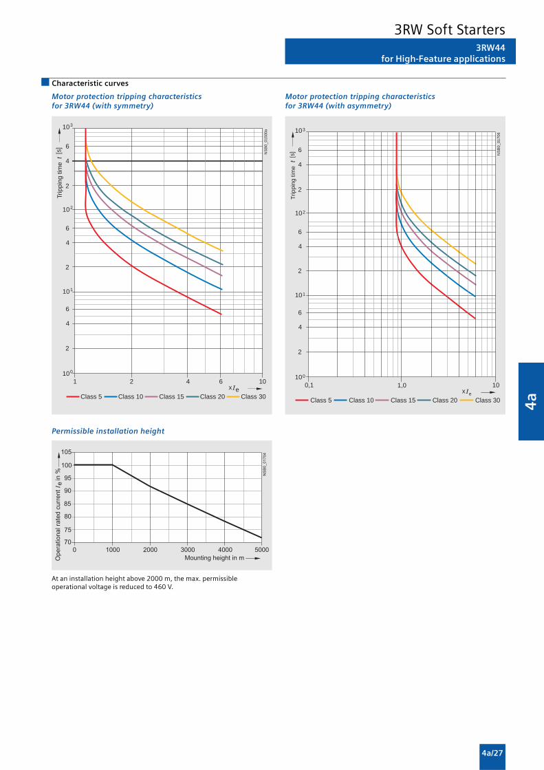
4a
4a/27
3RW44for High-Feature applications
Characteristic curves
Motor protection tripping characteristicsfor 3RW44 (with symmetry)
Permissible installation height
At an installation height above 2000 m, the max. permissibleoperational voltage is reduced to 460 V.
Motor protection tripping characteristicsfor 3RW44 (with asymmetry)
e2 4 6 101
Class 10 Class 15 Class 20
100
101
102
103
2
4
6
2
4
6
2
4
6
Class 5 Class 30
NS
B0_
0150
0a
[s]
x
Trip
ping
tim
e
e
100,1
Class 10 Class 15 Class 20
100
101
102
103
2
4
6
2
4
6
2
4
6
Class 5 Class 30
NS
B0_
0170
6
[s]
x1,0
Trip
ping
tim
e
3RW Soft Starters

4a
4a/28
Dimensional drawings
Project planning aids
3RW30/3RW31 for standard applications
3RW30 03-1. . . . (screw terminals)
1) For mounting onto standard mounting rail TH 35 according to EN 60715.2) Dimension for screw mounting.
Screw mounting with two 3RP1 903 push-in lugs per 3RW30 03 device.
3RW30 1. 3RW30 2. and 3RW31 2.
3RW30 3. 3RW30 4.
1) Drilling pattern.
��
����
������� �
���
��
���
� �
� � � �
� � � �� � � �
� � �
���
��
���
� �
�
�� �
��
��
��
���
��
��
�
�
�
��
�
��
��
����� ��
�
�
��
1)
NS
B00
434
35
115
7
5
125
101
63
14
45
6396
5
785
11981
� ����
� � � �
��
��
� �
� � � � �
�� � �
� �
�
���
�
���������
NSB00436
60
160
7
5
170
132
87
22,5
70
87156
5
8
108
162 1)
178
3RW Soft Starters

4a
4a/29
Project planning aids
3RW40 for standard applications
Type/Dimension a b c d e f g h I k l(mm)
3RW40 2. 125 45 92 149 126 14.4 63 5 6.5 35 115
3RW40 3. 170 55 110 165 140 18 63 5 6.5 30 150
3RW40 4. 170 70 110 183 158 22.5 85 5 10 60 160
Type/Dimension a b c d e f g h i k l m N o p q(mm)
3RW40 5. 180 120 37 17 167 100 223 250 180 148 6.5 153 7 198 9 M6, 10 Nm
3RW40 7. 210 160 48 25 190 140 240 278 205 166 10 166 9 230 11 M8, 15 Nm
k
l
fb h d
eg
c a 35N
SB
0_01
891
i
��
� �
� � ��
��
��
�
�
� � � � � � � � �
�
3RW Soft Starters

4a
4a/30
3RW44 2., 3RW44 3. and 3RW44 4. for High-Feature applications
Type/Dimension a b c d e f g h i k l m N o p q(mm)
3RW44 2. 180 170 37 11 167 100 240 270 180 148 7.5 153 7 184 6.6 M6, 10 Nm
3RW44 3. 180 170 37 17 167 100 240 270 180 148 7.5 153 7 198 9 M6, 10 Nm
3RW44 4. 210 210 48 25 190 140 269 298 205 166 16 166 9 230 11 M8, 15 Nm
�
�
��
� ��
�
�
�
�
� ��
� � � � � � �
�
Project planning aids
3RW Soft Starters

4a
4a/31
1) For M12 screw, tightening torque max. 35 Nm (310 lb.in).
3RW44 5. and 3RW44 6. for High-Feature applications
rs
w
qh
NS
B0_
0183
1
ad
tuv
p
no
m
a
ikl
e d
b
1)
c
f g
6T34T22T1
5L33L21L1
Type/Dimension a b c d e f g h i k l m(mm)
3RW44 5. 76 40 14 20 15.5 638.5 590 — 44 470 510 16.5
3RW44 6. 85 50 14 — — 667 660 160 37.5 535 576 16.5
Type/Dimension N o p q r s t u v W ad(mm)
3RW44 5. 105 253 623 — — — 249 162 152 — 290
3RW44 6. 103 251 693 43.5 40 20 249 162 151.4 123 290
3RW49 00-0AC00 external display and operator module Installation cutout for 3RW49 00-0AC00 external displayand operator module
SIRIUS 3RW44
DEVICE
SF
60
NS
B0_
0182
9
96 2829,135,6 N
SB
0_01
830
92
55
Project planning aids
3RW Soft Starters

4a
4a/32
Project planning aids
Schematics
3RW30/3RW31 connection examples for actuation with switches or auxiliary contacts
Control using switches Control using contactor contacts(for control of size S00 with pushbuttons)
3RW30 connection example for control with pushbuttons
(sizes S0, S2, and S3 only)
����������
! " ! # #
$ � % $ & � % $ ' �
( ) ( � * �
� � �
��������)� $ � % $ & �
!
! # #
* �
( )
( �
% $ ' �
+ ) �
+ ) �
+ ) �
$ � % $ & �
% $ ' �
� � �
NS
B0_
0041
6b
N(L-) L1(L+)
A2 A1 IN1
Q11
13 14 24
ON
OFF
23
3RW Soft Starters

4a
4a/33
Project planning aids
3RW30/3RW31 connection examples for main circuit1)
3RW303-phase motors
3RW303-phase motorswith motor starterprotector
3RW301-phase motorswith 3RV motor starterprotector
# �
����������
, -
. /+ ) �
. 0 " . � ) �
. 1 �� � �
����������
. 2
3, -
. 1 �� � �
�������)��
$
+ � �
+ �
3 3 3� � �
,� -
3RW Soft Starters

4a
4a/34
3RW40 2. ... 3RW40 4. connection examples for control circuit
Control using switches With remote reset Automatic mode
Project planning aids
Control of 3RW40 2. ... 3RW40 4.by pushbutton
A2
ON/OFF
L1 (L +)N(L-)
1A1
Q11
NS
B0_
0191
4
1)
A2
ON/OFF
L1 (L +)N(L-)
1
RESET
A1
Q11
NS
B0_
0189
2
1)
A2 A1 1
ON/OFF
N(L-) L1(L+)
Q11
NS
B0_
0189
5
1)
NS
B0_
0191
5
>1,5 s
Us
100 %
t
>5 min
Us
ON
OFF t
NS
B0_
0191
6a
N(L-) L(L+)
NS
B0_
0189
6
A2A1 1
Q11
ON
ON
13 23
OFF
14 24NO NO
Connection example of 3RW40 2. ... 3RW40 4.for PTC sensors (thermistor motor protection)
Thermoclick PTC type A
1) Caution: Risk of restartingWhen operating with a switch (ON/OFF) a new, automatic restart willtake place automatically if the start command is still active at terminal 1.
ϑ
T11/T21 T22T12
NS
B0_
0189
3
Q11
ϑ
T11/T21 T12 T22
NS
B0_
0189
4
Q11
3RW Soft Starters

4a
4a/35
Project planning aids
3RW40 5. and 3RW40 7. connection examplesfor control circuit
Control by switch usinginternal 24 V DC supply external power supply
$ �
( � ( ) � )
����������
! " ! # #
) �
� �
� � �
( � ( ) � )
��������)�
! " ! # # � �
) �
$ �
� � �
Control by pushbuttonN
SB
0_01
483b
NL1
A2A1 1
Q11
2 3
ON
2)
ON
13 23 95 96 98
OVERLOADFAILURE
OFF
14 24NO NO NC NO
Control of a main contactor
NS
B0_
0148
4b
NL1
A2A1 1
Q11
2 3
2)
RUN
13 23 95 96 98
OVERLOADFAILURE
14 24NO NO NC NO
Q21
ON/OFF 1)
3RW40 connection examples for main circuit3)
3RW40 – 3-phase motor with 3RV motor starter protectors/3NA/3NE fuse 3VL circuit breakers
1) Caution: Risk of restartingWhen operating with a switch (ON/OFF) a new, automatic restart willtake place automatically if the start command is still active at terminal 3.
2) Grounding necessary for fan connection to 3RW40 5...3) As an alternative, the motor feeder can also be installed as a fuseless or
as a fused version. For fuse and switching device coordination, see“Technical specifications”.The wiring diagrams are provided only as examples.
NS
B0_
0148
9b
M3~
3RT
F1
Q11
Q21
3RW40
3NA/3NE
NS
B0_
0148
7b
M3~
3VL
Q11 3RW40
3RW Soft Starters

4a
4a/36
3RW44 connection examples for main and control circuitsMain circuit Control circuit
Possibility 1a: Possibility 1:Inline circuit with motor starter protector and SITOR fuse Control by pushbutton(semiconductor protection only)
NS
B0_
0149
0b
(optionalsemiconductor protection fuse)
M3~
Q11
L1 3/N/PE 400 V AC, 50 HzL2L3
PE
L1 L2 L3
T1 T2 T3
Q1
F3
M1U1 V1 W1
NSB0_01494b
PE+
L1 1/N/PE 230 V AC 1), 50 Hz
PTC type Aor
Thermoclick
StopS1
On periodNoaction
Noaction
Grouperror
Mot
or o
n rig
htP
S 1
No
actio
n
No
actio
n
Q11
PE
IN1 T1 T2
F2
N
L+ L-A1 IN2 IN3 IN4
A2 13 14 23 24 33 34 95 9896
Sta
rt S
2
Res
et S
3
Main circuit
Possibility 1b: Possibility 1c:Inline circuit with full-range Inline circuit with line andprotection SITOR fuse(line and semiconductor protection) (semiconductor protection only)
1) Permissible values for main and control voltage, see “Technicalspecifications”.
+ � �
$ � $ ) $
/ � / ) /
, �
���������
# 4 �
2 �0 � 1 �
,5 6 -
$ $ )$ � � � " " 5 6 7 � � � 7 2 7 ( 8 7 7 � 7 � � 7 9 :
+ � �
#
$ � $ ) $
/ � / ) /
, �
�������)�
# �
2 �0 � 1 �
,5 6 -
$ $ )$ � � � " " 5 6 7 ( 8 7 � � � 7 2 7 7 � 7 � � 7 9 :
Project planning aids
3RW Soft Starters

4a
4a/37
Main circuit Control circuit
Possibility 2: Possibility 2:Inline circuit with main contactor Control of a main contactor and control by means of PLC
1) Permissible values for main and control voltage, see “Technicalspecifications”.
2) Caution. Risk of restarting!The start command (e.g. from the PLC) must be reset prior to a resetcommand because a new, automatic restart will take place automaticallyif a start command is active after the reset command. This appliesespecially in case of motor protection tripping.For safety reasons we recommend incorporating the group error output(terminals 95 and 96) in the controller.
NS
B0_
0149
5b
(optionalsemiconductor protection fuse)(optional linecontactor if floatingswitching of themotor is planned)
L1 3/N/PE 400 V AC 1), 50 Hz
M3~
Q11
L2L3
PE
L1 L2 L3
T1 T2 T3
Q1
F3
M1U1 V1 W1
Q21
NSB0_01496b
+
L1 1/N/PE 230 V AC 1), 50 Hz
PTC type A orThermoclick
No action
Group error
Mot
or ri
ght
PS
1
No
actio
n
No
actio
n
No action
Switch-on duration
(optional line contactorif floating switching of the motor is planned)
PLC outputs PLC inputs
Trip
Res
et
Reset Start 2)
Q11
PE
IN1 T1 T2
F2
N
L+ L-A1 IN2 IN3 IN4
A2 13 14 23 24 33 34 95 9896
PE
Q21
+24 V DC
M
Project planning aids
3RW Soft Starters

4a
4a/38
Project planning aids
Main circuit Control circuit
Possibility 3a: Possibility 3a:Inline circuit with ramp-down function DC braking3) Control of the DC braking contactor3)
(for device types 3RW44 22 to 3RW44 25)N
SB
0_01
501b
L1 3/N/PE 400 V AC 1), 50 Hz
(optionalsemi-conductorprotection)
M3~
Q11
L2L3
PE
L1 L2 L3
T1 T2 T3
Q1
F3
M1U1 V1 W1
Q912
Q91 Q91
NSB0_01502a
+
L1 1/N/PE 230 V AC 1), 50 Hz
PTC type A orThermoclick
No action Group error
No
actio
n
No
actio
n
Switch-on duration
PLC output
Res
et
Reset Start 2)
DC braking contactor 3)
Q11
PE
IN1 T1 T2
F2
N
L+ L-A1 IN2 IN3 IN4
A2 13 14 23 24 33 34 95 9896
PE
+24 V DC
M
Q91
Q91
Main circuit Control circuit
Possibility 3b: Possibility 3b:Inline circuit with ramp-down function DC braking3) Control of the DC braking contactor3)
(for device types 3RW44 26 to 3RW44 47)
NS
B0_
0150
3b
L1 3/N/PE 400 V AC 1), 50 Hz
(optionalsemi-conductorprotection)
M3~
Q11
L2L3
PE
L1 L2 L3
T1 T2 T3
Q1
F3
M1U1 V1 W1
Q92Q913 3
NSB0_01504a
+
L1 1/N/PE 230 V AC 1), 50 Hz
PTC type A orThermoclick
No action Group error
No
actio
n
No
actio
n
Switch-on duration
PLC output
Res
et
Reset Start 2)
DC braking contactor 3)
Mot
or ri
ght
PS
1
Q11
PE
IN1 T1 T2
F2
N
L+ L-A1 IN2 IN3 IN4
A2 13 14 23 24 33 34 95 9896
PE
+24 V DC
M
Q91
Q92
K4
Q92
Q91
K4
4)K4
1) Permissible values for main and control voltage, see “Technicalspecifications”.
2) Caution. Risk of restarting!The start command (e.g. from the PLC) must be reset prior to a resetcommand because a new, automatic restart will take place automaticallyif a start command is active after the reset command. This appliesespecially in case of motor protection tripping.For safety reasons we recommend incorporating the group error output(terminals 95 and 96) in the controller.
3) If the ramp-down function “Combined braking” is selected, no brakingcontactor is required.If the ramp-down function “DC braking” is selected, a braking contactormust be used in addition. For type see “Fuse Assignment (Inline Circuit)”on pages 6/38 to 6/40.For applications with large centrifugal masses (JLoad > JMotor) werecommend the function “DC braking”.The output 2 must be switched over to “DC braking contactor”.
4) Auxiliary relay K4, e.g.:LZX:RT4A4T30 (230 VAC rated control supply voltage),LZX:RT4A4S15 (115 VAC rated control supply voltage).
3RW Soft Starters
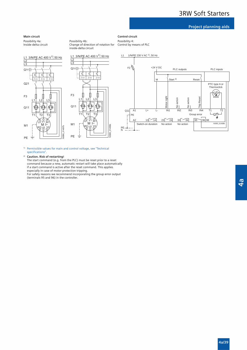
4a
4a/39
Project planning aids
Main circuit Control circuit
Possibility 4a: Possibility 4b: Possibility 4:Inside-delta circuit Change of direction of rotation for Control by means of PLC
inside-delta circuit
,2 � 1 �
0 )
0 �
1 ) 2 )
+ � �
, �
���������
$ � $ ) $
/ � / ) /
+ �
#
+ ) �
5 6
-
$ $ )
� �$ � 7 7 " " 5 6 7 ( 8 7 � � � 7 2 7 7 � 7 � � 7 9 :
$ � $ ) $
/ � / ) /
, �
��������,
2 �0 � 1 �
0 )1 ) 2 )
5 6
-
+ �
$ $ )
� �
+ � �
#
$ � 7 7 " " 5 6 7 ( 8 7 � � � 7 2 7 7 � 7 � � 7 9 :
NSB0_01498b
+
L1 1/N/PE 230 V AC 1), 50 Hz
PTC type A orThermoclick
No action
Group error
Mot
or ri
ght
No
actio
n
No
actio
n
No actionSwitch-on duration
PLC outputs PLC inputs
Trip
Res
et
Reset Start 2)
Q11
PE
IN1 T1 T2
F2
N
L+ L-A1 IN2 IN3 IN4
A2 13 14 23 24 33 34 95 9896
PE
+24 V DC
M
1) Permissible values for main and control voltage, see “Technicalspecifications”.
2) Caution. Risk of restarting!The start command (e.g. from the PLC) must be reset prior to a resetcommand because a new, automatic restart will take place automaticallyif a start command is active after the reset command. This appliesespecially in case of motor protection tripping.For safety reasons we recommend incorporating the group error output(terminals 95 and 96) in the controller.
3RW Soft Starters

4a
4a/40
Technical specifications
General data
3RE19 13 3RE19 23 3RE19 33
General data
Standards• IEC 60947-1, EN 60947-1 (VDE 0660 Part 100) Yes• IEC 60947-5, EN 60947-5 (VDE 0660 Part 200) Yes• IEC 60947-2, EN 60947-2 (VDE 0660 Part 101) Yes
Size S00 S0 S0
Max. rated current In max = (Max. rated operational current Ie) A 12 25 50
Rated insulation voltage Ui (degree of pollution 3) V 400
Rated impulse withstand voltage Uimp kV 4
Ambient temperature• Operation °C -20 ... +35 (current reduction is necessary above +35 °C)• Storage °C -55 ... +80
Degree of protection acc. to IEC 60947-1 IP65
Touch protection acc. to EN 50274 (VDE 0660 Part 514) Finger-safe
Installation altitude m Up to 2000 above sea level; above this, please enquire
Permissible rated current In
• Overload relay for ambient temperature: +35 °C % 100• Overload relay for ambient temperature: +45 °C % 87
Mounting position For installation in the hatched area, a setting correction of 10 % must beimplemented.
NSB01363a135°
0°22,5° 22,5°
135°
� e
0°
x 1,1
Contactor + overload relay
Conductor cross-sections 1)
Short-circuit protection
Main circuit 2)
Auxiliary circuit 1)
3RE Encapsulated Starters

4a
4a/41
Project planning aids
Dimensional drawings
Direct-on-line starter, size S00
3RE19 13-1CB1metric cable gland M25
������
��
�
�
�
�
���
����
��
��
Direct-on-line starter, size S2
3RE19 33-1CB3
Reversing starter, size S00/S0
3RE19 23-2CB3metric cable gland M32
��
�
�
�
��
��
��
�����
Direct-on-line starter, size S0
3RE19 23-1CB2metric cable gland M25
������
��
�
�
�
���
�����
��
��
3RE Encapsulated Starters

4a
4a/42
Schematics
Project planning aids
Direct-on-line starter, size S00/S0
3RE19 13-1CB1 (see Accessories)3RE19 23-1CB2 (see Accessories)
� �
� � �
� � �
�
� � � �
� � � �
�
�
�
��
� �
� �
� �
� �
� �� � � �
� � � � � � �
�� �
���
� � �
� � �
� �
� �
� ��
� �
� � � �
� � � �
� �
� � � ! � � � � �
� " # $ # � � # % # �
� " # $ # � � # % # � �
Reversing starter, size S00
3RE19 13-2CB3 (see Accessories)
��
��
��
��
��
��
��
��
��
��
� � �
� � �
� � �
� � �
� � �
� � �
��
��
��
��
��
��
����������
��
��
��
��
��
��
��
��
��
�� ��
����
��
��
��
��
��
��
��
�����������
��
��
���������
�������� �
�������� ���
�������
Direct-on-line starter, size S2
3RE19 33-1CB3 (see Accessories)
Reversing starter, size S0
3RE19 13-2CB3
��
� � �
� � �
��
��
��
��
��
��
���
!�
�!
"�
��
!
�!
#�
��
��
��
� � �
� � �
#��
����
��
��
��
��
��
��
�$
�%
��
���������
�������� �
�������� ���
��
��
��
��
��
��
��
��
��
��
� � �
� � �
� � �
� � �
� � �
� � �
��
��
��
��
��
��
��
���
���
��
���
���
��
��
��
��
�� ��
����
��
��
��
��
��
��
��
�����������
��
��
���������
�������� �
�������� ���
3RE Encapsulated Starters

Monitoring andControl Devices
5/2 Introduction
SIMOCODE 3UF Motor Managementand Control Devices
5/4 SIMOCODE pro 3UF7
motor management and control devices
3RP Timing Relays
5/14 3RP15 timing relays in industrialenclosure, 22.5 mm
Monitoring Relays
3UG Monitoring Relays
for Electrical and Additional Measurements
5/19 Line monitoring
5/21 Power factor and active currentmonitoring
Residual Current Monitoring
5/22 - Residual-current monitoring relays
5/23 - Summation current transformers
Insulation monitoring
5/24 - for ungrounded AC networks
3RN1 Thermistor Motor Protection
5/26 For PTC sensors
3TK28 Safety Relays
5/28 General data
5/29 With electronic enabling circuits
5/33 With relay enabling circuits
5/35 With contactor relay enabling circuits
5/37 With special functions
5

5
5/2
Introduction
Overview
SIMOCODE pro 3UF7 • Compact, modular design 3UF7 5/14
• Unique flexibility in terms of functionality and hardwareconfiguration
• Wide functional range from the distributed I/O system to theautonomous motor management system
• All control functions from the direct-on-line starter to thepole-changing switch with reversing contactor
• All motor sizes• Integration in all PROFIBUS-capable automation systems
Monitoring and Control Devices
The advantages at a glance
SIMOCODE 3UF motor management and control devices
Type Page
3RP15 timing relay in industrial enclosure, • Low-cost solution with monofunctions such as response 3RP15 5/1422.5 mm delay, OFF-delay, clock-pulse, wye-delta function,
multifunction• Wide-range voltage designs
3RP, 3RT19 timing relays
3PR153UF7
Line monitoring
Phase sequence • Low-cost solution for monitoring the phase sequence 3UG45 11 5/19
Phase sequence, phase failure, phase unbalance • Wide voltage range from 160 ... 690 V 3UG45 12 5/19
Phase sequence, phase failure, phase unbalance • Analogically adjustable 3UG45 13 5/19and undervoltage • Wide voltage range from 160 ... 690 V
• Digitally adjustable with LCD display 3UG46 14 5/19for indication of ACTUAL value and device status
• Wide voltage range from 160 ... 690 V
Phase sequence, phase failure, phase unbalance • Digitally adjustable with LCD display 3UG46 15 5/19over limit values, overvoltage and undervoltage for indication of ACTUAL value and device status
Phase sequence, phase and N conductor failure, Wide voltage range from 160 ... 690 V 3UG46 16 5/19phase unbalance over limit values, overvoltageand undervoltage
Power factor and active current monitoring (motor load monitoring)
Power factor and active current monitoring with • For monitoring over the entire torque rangeinternal power supply for overshoot, • Digitally adjustable with LCD display for indicationundershoot or window monitoring of ACTUAL value and device status
• Wide voltage range from 90 ... 690 V 3UG46 41 5/21
Residual current monitoring
Residual-current monitoring relays • Digitally adjustable with LCD display for indicationof ACTUAL value and device status
• Adjustable threshold values for warning and disconnection• For plant monitoring• Wide voltage range from 90 ... 690 V 3UG46 24 5/22
Summation current transformers • For detection of fault currents in machines and plants 3UL22 5/23
Insulation monitoring
Monitoring of the insulation resistance • Test button 3UG30 81, 5/24for ungrounded AC or DC networks • With or without storagefrom 1 ... 110 kΩΩΩΩΩ • Switchable measuring range
3UG monitoring relays for electrical and additional measurements
3UG46 163UG45 11

5
5/3
Introduction
Monitoring and Control Devices
3RN1 thermistor motor protectionFor PTC sensors • Relays for monitoring motor winding temperatures with 3RN1 5/26
type A PTC sensors• Integrated with ATEX approval• Closed-circuit principle• Depending on the version: With short-circuit and open-circuit
detection, zero voltage safety, manual/auto/remote RESET,1 CO, 1 NO + 1 NC, 2 CO, 1 NO + 1 CO or2 CO hard gold-plating
3TK28 safety relaysWith electronic enabling circuits • Permanent function checking 3TK28 4 5/30
• No wear because switched electronically• High switching frequency• Long electrical endurance• Evaluation of solid-state sensors• Sensor lead up to max. 2000 m• Cascading possible• Insensitive to vibrations and dirt• Compact design, low weight• Approved for the world market
With relay enabling circuits • Compact design 3TK28 2, 5/33• Floating safe outputs 3TK28 3• Also suitable for press and punch controls• Can be used up to an ambient temperature of max. 70 °C
With contactor relay enabling circuits • Enabling circuits, floating 3TK28 5 5/35• AC-15/DC-13 switching capacity• Safe isolation• Long mechanical and electrical endurance• Certified as a complete unit• Fault minimization and cost reduction through factory wiring• Low installation costs
With special functions • Floating safe outputs 3TK28 1 5/37• Signaling outputs for status and diagnostics signals• Safe standstill monitoring
The advantages at a glance
Type Page
3TK283RN1
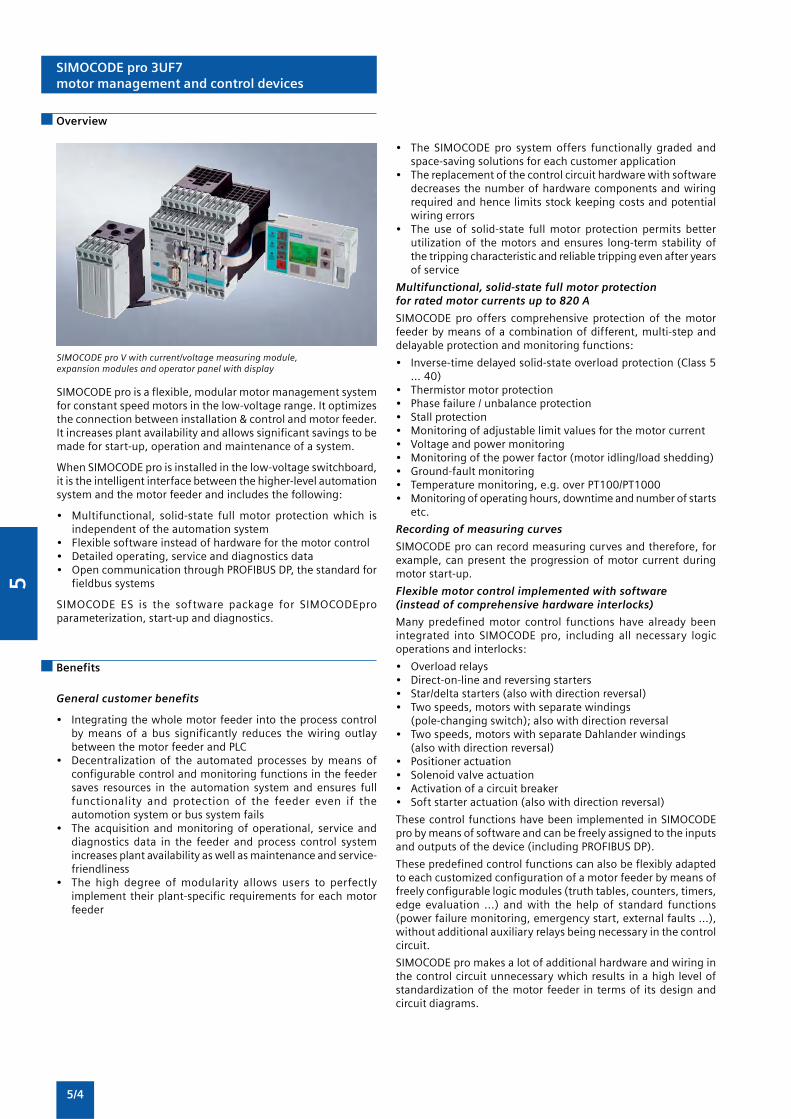
5
5/4
SIMOCODE pro 3UF7motor management and control devices
Overview
SIMOCODE pro V with current/voltage measuring module,expansion modules and operator panel with display
SIMOCODE pro is a flexible, modular motor management systemfor constant speed motors in the low-voltage range. It optimizesthe connection between installation & control and motor feeder.It increases plant availability and allows significant savings to bemade for start-up, operation and maintenance of a system.
When SIMOCODE pro is installed in the low-voltage switchboard,it is the intelligent interface between the higher-level automationsystem and the motor feeder and includes the following:
• Multifunctional, solid-state full motor protection which isindependent of the automation system
• Flexible software instead of hardware for the motor control• Detailed operating, service and diagnostics data• Open communication through PROFIBUS DP, the standard for
fieldbus systems
SIMOCODE ES is the software package for SIMOCODEproparameterization, start-up and diagnostics.
Benefits
General customer benefits
• Integrating the whole motor feeder into the process controlby means of a bus significantly reduces the wiring outlaybetween the motor feeder and PLC
• Decentralization of the automated processes by means ofconfigurable control and monitoring functions in the feedersaves resources in the automation system and ensures fullfunctionality and protection of the feeder even if theautomotion system or bus system fails
• The acquisition and monitoring of operational, service anddiagnostics data in the feeder and process control systemincreases plant availability as well as maintenance and service-friendliness
• The high degree of modularity allows users to perfectlyimplement their plant-specific requirements for each motorfeeder
• The SIMOCODE pro system offers functionally graded andspace-saving solutions for each customer application
• The replacement of the control circuit hardware with softwaredecreases the number of hardware components and wiringrequired and hence limits stock keeping costs and potentialwiring errors
• The use of solid-state full motor protection permits betterutilization of the motors and ensures long-term stability ofthe tripping characteristic and reliable tripping even after yearsof service
Multifunctional, solid-state full motor protectionfor rated motor currents up to 820 A
SIMOCODE pro offers comprehensive protection of the motorfeeder by means of a combination of different, multi-step anddelayable protection and monitoring functions:
• Inverse-time delayed solid-state overload protection (Class 5... 40)
• Thermistor motor protection• Phase failure / unbalance protection• Stall protection• Monitoring of adjustable limit values for the motor current• Voltage and power monitoring• Monitoring of the power factor (motor idling/load shedding)• Ground-fault monitoring• Temperature monitoring, e.g. over PT100/PT1000• Monitoring of operating hours, downtime and number of starts
etc.
Recording of measuring curves
SIMOCODE pro can record measuring curves and therefore, forexample, can present the progression of motor current duringmotor start-up.
Flexible motor control implemented with software(instead of comprehensive hardware interlocks)
Many predefined motor control functions have already beenintegrated into SIMOCODE pro, including all necessary logicoperations and interlocks:
• Overload relays• Direct-on-line and reversing starters• Star/delta starters (also with direction reversal)• Two speeds, motors with separate windings
(pole-changing switch); also with direction reversal• Two speeds, motors with separate Dahlander windings
(also with direction reversal)• Positioner actuation• Solenoid valve actuation• Activation of a circuit breaker• Soft starter actuation (also with direction reversal)
These control functions have been implemented in SIMOCODEpro by means of software and can be freely assigned to the inputsand outputs of the device (including PROFIBUS DP).
These predefined control functions can also be flexibly adaptedto each customized configuration of a motor feeder by means offreely configurable logic modules (truth tables, counters, timers,edge evaluation ...) and with the help of standard functions(power failure monitoring, emergency start, external faults ...),without additional auxiliary relays being necessary in the controlcircuit.
SIMOCODE pro makes a lot of additional hardware and wiring inthe control circuit unnecessary which results in a high level ofstandardization of the motor feeder in terms of its design andcircuit diagrams.

5
5/5
SIMOCODE pro 3UF7motor management and control devices
Detailed operational, service and diagnostics data
SIMOCODE pro makes different operational, service anddiagnostics data available and helps to detect potential faults intime and to prevent them by means of preventative measures. Inthe event of a malfunction, a fault can be diagnosed, localizedand rectified very quickly - there are no or very short downtimes.
Operating data
• Motor switching state derived from the current flow in themain circuit
• All phase currents• All phase voltages• Active power, apparent power and power factor• Phase unbalance and phase sequence• Time to trip• Motor temperature• Remaining cooling time etc.
Service data
• Motor operating hours• Motor stop times• Number of motor starts• Number of overload trips• Consumed power• Internal comments stored in the device etc.
Diagnostics data• Numerous detailed early warning and fault messages• Internal device fault logging with time stamp• Time stamping of freely selectable status, alarm or fault
messages etc.
CommunicationSIMOCODE pro is equipped with an integral PROFIBUS DP interface(SUB-D or terminal connection) and can therefore replace allindividual wiring (including modular terminals), which wouldusually be required for exchanging data with the higher-levelautomation system, with a single 2-wire cable.
SIMOCODE pro supports among other things:• Baud rates up to 12 Mbit/s• Automatic baud rate detection• Communication with up to 3 masters• Time synchronization over PROFIBUS• Cyclic services (DPV0) and acyclic services (DPV1)• DPV1 communication after the Y-Link etc.
SIMOCODE pro combines all the necessary functions for the motor feeder in a compact system.
���������
�� �
��� ��
��
�� �
�������
���
������������ ���������������
�!"#$%��&
�����������'����(���)���
$�'�������
!*�������*����
�#�!�!&+�*��
�������������,��
���������)��������-�.�����)/��0����'���/�����0�1�����)���������2223
�������������-����2����������(�4���������5��(3
�������������-�*���������/�'��.���/�)��(��'����)���
4���������������)'3
�������������.��

5
5/6
SIMOCODE pro 3UF7motor management and control devices
Application
SIMOCODE pro is often used for automated processes where plantdowntimes are very expensive (e.g. steel or cement industry)and where it is important to prevent plant downtimes throughdetailed operational, service and diagnostics data or to localizethe fault very quickly in the event of a fault.
SIMOCODE pro is modular and space-saving and suited especiallyfor operation in motor control centers in the process industryand for power plant technology.
Applications
Protection and control of motors• In hazardous areas for types of protection EEx e/d according
to ATEX directive 94/9/EC
• With heavy starting (paper, cement, metal and waterindustries)
• In high-availability plants (chemical, oil, raw materialprocessing industry, power plants)
Industries
Today, SIMOCODE pro is mainly used in the chemical (incl. oiland gas), steel, water, paper, pharmaceutical, cement, and glassindustry. It is also used for applications in power plants and largediamond, gold and platinum mines.
An essential requirement in these industries is the availability ofthe motors and thus the availability of the whole process. Plantdowntimes caused by faults frequently result in high costs. Forthis reason, it is very important to detect potential faults early onand to initiate targeted countermeasures. SIMOCODE pro offersusers an up-to-date motor management system based on yearsof experience.
More Information
Important ordering notes
SIMOCODE pro is a modularly constructed motor managementsystem which is subdivided into two device series with differentfunctional scopes:
SIMOCODE pro C,as a compact system for direct-on-line starters and reversingstarters
SIMOCODE pro V,as a variable system with all control functions and with thepossibility of expanding the inputs, outputs and functions of thesystem at will using expansion modules.
Expansion possibilities SIMOCODE pro C, SIMOCODE pro V,Basic Unit 1 Basic Unit 2
Operator panelOperator panel with display --
Current measuring modulesCurrent/voltage measuring modules --Decoupling module --
Expansion modules: --Digital modules (max. 2) --Analog module (max. 1) --Earth-lealcase module (max. 1) --Temperature module (max. 1) --
Possible
-- Not available
Note:
When an operator panel with display and/or a decoupling moduleis used, restrictions on the number of expansion modulesconnectable per basic unit must be observed see TechnicalInformation!

5
5/7
SIMOCODE pro 3UF7motor management and control devices
Selection and ordering data
Version Current setting Width Screw terminals WeightOrder No. Per PU
approx.
A mm kg.
SIMOCODE pro C, basic units 1PROFIBUS DP interface, 12 Mbit/s, RS 4854 I/3 O freely assignable, input for thermistor connection,monostable relay outputs,rated control supply voltage Us:• 24 V DC 3UF7 000-1AB00-0 0.350• 110 ... 240 V AC/DC 3UF7 000-1AU00-0 0.350
SIMOCODE pro V, basic units 2PROFIBUS DP interface, 12 Mbit/s, RS 4854 I/3 O freely assignable, input for thermistor connection,monostable relay outputs,can be expanded with expansion modules,rated control supply voltage Us:• 24 V DC 3UF7 010-1AB00-0 0.350• 110 ... 240 V AC/DC 3UF7 010-1AU00-0 0.350
Current measuring modules
Straight-through 0.3 ... 3 45 3UF7 100-1AA00-0 0.100transformers
2.4 ... 25 45 3UF7 101-1AA00-0 0.15010 ... 100 55 3UF7 102-1AA00-0 0.35020 ... 200 120 3UF7 103-1AA00-0 0.600
Busbar connections 20 ... 200 120 3UF7 103-1BA00-0 1.00063 ... 630 145 3UF7 104-1BA00-0 1.750
Current/voltage measuring modulesVoltage measuring up to 690 Vif required in connection with a decoupling moduleStraight-through 0.3 ... 3 45 3UF7 110-1AA00-0 0.150transformers
2.4 ... 25 45 3UF7 111-1AA00-0 0.20010 ... 100 55 3UF7 112-1AA00-0 0.40020 ... 200 120 3UF7 113-1AA00-0 0.700
Busbar connections 20 ... 200 120 3UF7 113-1BA00-0 1.00063 ... 630 145 3UF7 114-1BA00-0 1.750
Decoupling modulesFor connecting upstream from a current/voltage 3UF7 150-1AA00-0 0.150measuring module on the system interface when usingvoltage detection in non-earthed networks
Operator panelsInstallation in control cabinet door or front plate, 3UF7 200-1AA00-0 0.100for plugging into basic unit, 10 LEDs for status indicationand user-assignable buttons for controlling the motor
Operator panels with display for SIMOCODE pro V1)
Installation in control cabinet door or front plate, 3UF7 210-1AA00-0 0.150for plugging into basic unit 2, 7 LEDs for statusindication and user-assignable buttons for controllingthe motor, multilingual display, e.g. for indication ofmeasured values, status information or faultmessages
1) Only possible with basic unit 2, product version EO3 and higher (from 12/2006)
SIMOCODE pro
3UF7 000-1A.00-0
3UF7 010-1A.00-0
3UF7 100-1AA00-0
3UF7 110-1AA00-0
3UF7 150-1AA00-0
3UF7 200-1AA00-0
3UF7 210-1AA00-0

5
5/8
SIMOCODE pro 3UF7motor management and control devices
Selection and ordering data
Version Current setting Width Screw terminals WeightOrder No. Per PU
approx.
A mm kg.
Note:Expansion modules can only be used in combination with basic unit 2! A total of upto 5 expansion modules can be connected in any order to one basic unit. When anoperator panel with display and/or a decoupling module is used, more restrictionson the number of expansion modules connectable per basic unit must be observed!
Digital modules4 binary inputs and 2 relay outputs,up to 2 digital modules can be connected per basicunit 2Relay outputs Input voltageMonostable 24 V DC 3UF7 300-1AB00-0 0.150
110 ... 240 V AC/DC 3UF7 300-1AU00-0 0.150Bistable 24 V DC 3UF7 310-1AB00-0 0.150
110 ... 240 V AC/DC 3UF7 310-1AU00-0 0.150
Analog modules2 inputs (passive) for input and 1 output for output 3UF7 400-1AA00-0 0.150of 0/4 ...20 mA signals,max. 1 analog module can be connected per basicunit 2
Earth-leakage modules1 input for connecting a summation current 3UF7 500-1AA00-0 0.150transformer 3UL22,up to 1 ground-fault module can be connected perbasic unit 2Note:For the corresponding summation current transformersfor rated fault currents of 0.3 A, 0.5 A or 1 Asee page 7/55.
Temperature modules3 inputs for connecting up to 3 analog temperature 3UF7 700-1AA00-0 0.150sensors, up to 1 temperature module can beconnected per basic unit 2
Expansion modules
3UF7 300-1AU00-0
3UF7 400-1AA00-0
3UF7 500-1AA00-0
3UF7 700-1AA00-0

5
5/9
SIMOCODE pro 3UF7motor management and control devices
Accessories
Version Order No. WeightPer PUapprox.
kg.
Connection cablesIn different lengths for connecting basic unit, currentmeasuring module, current/voltage measuringmodule, operator panel or expansion modules ordecoupling module:Length 0.025 m (flat) 3UF7 930-0AA00-0 0.010Note: Only suitable for connecting basic unit 2to its expansion modules or for connecting expansionmodules to each other; only when the front platesfinish at the same height!• Length 0.1 m (flat) 3UF7 931-0AA00-0 0.010• Length 0.3 m (flat) 3UF7 935-0AA00-0 0.020• Length 0.5 m (flat) 3UF7 932-0AA00-0 0.020
• Length 0.5 m (round) 3UF7 932-0BA00-0 0.050• Length 1.0 m (round) 3UF7 937-0BA00-0 0.100• Length 2.5 m (round) 3UF7 933-0BA00-0 0.150
For PC/PG communication with SIMOCODE prothrough the system interface, for connecting to the 3UF7 940-0AA00-0 0.150serial interface of the PC/PG
The memory module enables the complete parameter 3UF7 900-0AA00-0 0.010assignment of a system to be saved and transferredto a new system, e.g. when a device is replaced,without the need for additional aids or detailedknowledge of the the system interface
For system interface 3UF7 950-0AA00-0 0.100
For assigning the PROFIBUS addresses without using a PC/PG 3UF7 910-0AA00-0 0.030on SIMOCODE pro through the system interface
For external connection of the system interface 3UF7 920-0AA00-0 0.030outside, for example, a control cabinet
The adapter enables the smaller 3UF7 20 operator 3UF7 922-0AA00-0 0.150panel from SIMOCODE pro to be used in a front panelcutout in which previously, e.g. after a change of system,a larger 3UF5 2 operator panel from SIMOCODE-DPhad been used; degree of protection IP54
Connection cables (essential accessory)
PC cables
Memory modules
Interface covers
Addressing plugs
Door adapters
Adapters for operator panel
3UF7 932-0AA00-0
3UF7 900-0AA00-0
3UF7 950-0AA00-0
3UF7 920-0AA00-0
3UF7 922-0AA00-0
3UF7 940-0AA00-0
3UF7 920-0AA00-0

5
5/10
SIMOCODE pro 3UF7motor management and control devices
Accessories
Version Order No. WeightPer PUapprox.
kg.
• For pushbuttons of the 3UF7 20 operator panel 3UF7 925-0AA00-0 15.000• For pushbuttons of the 3UF7 21 operator panel with 3UF7 925-0AA01-0 15.000
displayFor LEDs of the 3UF7 20 operator panel 3UF7 925-0AA02-0 15.000
Note: Pre-punched labeling strips for user-specificprinting using the free inscription software"SIRIUS Label Designer" on a laser printer.Note the software version!Download from www.siemens.de/simocode.
For screw mountinge.g. on mounting plate, 2 units required per device
• Can be used with 3UF7 1.0, 3UF7 1.1 and 3UF7 1.2 3RB19 00-0B 0.100
• Can be used with 3UF7 0, 3UF7 3, 3UF7 4, 3UF7 5and 3UF7 7 3RP19 03 0.002
Covers for cable lugs and busbar connections• Length 100 mm, can be used for 3UF7 1.3-1BA00-0 3RT19 56-4EA1 0.170
• Length 120 mm, can be used for 3UF7 1.4-1BA00-0 3RT19 66-4EA1 0.130
Covers for box terminals• Length 25 mm, can be used for 3UF7 1.3-1BA00-0 3RT19 56-4EA2 0.030
• Length 30 mm, can be used for 3UF7 1.4-1BA00-0 3RT19 66-4EA2 0.040
Covers for screw terminalsbetween contactor and current measuring moduleor current/voltage measuring module for direct mounting• Can be used for 3UF7 1.3-1BA00-0 3RT19 56-4EA3 0.020
• Can be used for 3UF7 1.4-1BA00-0} 3RT19 66-4EA3 0.060
For round and ribbon cables• Up to 70 mm2, can be used for 3UF7 1.3-1BA00-0 3RT19 55-4G 0.230
• Up to 120 mm2, can be used for 3UF7 1.3-1BA00-0 3RT19 56-4G 0.260
• Up to 240 mm2, can be used for 3UF7 1.4-1BA00-0 3RT19 66-4G 0.676
For conductor cross-sections, see
Technical Information.
SIMOCODE proWith token fee,languages:• German 3UF7 970-0AA01-0 0.850
• English 3UF7 970-0AA00-0 0.850
• French 3UF7 970-0AA02-0 0.850
Labelling strips
Push-in lugs
Terminals covers
Boc terminal blocks
System manuals
3UF7 925-0AA02-0
3RB19 00-0B
3RT 19 56-4EA1
3RT 19 56-4EA2
3UF7 970-0AA01-0
3RT 19 5.-4G

5
5/11
SIMOCODE pro 3UF7motor management and control devices
Accessories
PCS 7 function block library for SIMOCODE pro
3UF7 982-0AA00-0
Version Order No. WeightPer PUapprox.
kg.
For integrating SIMOCODE pro into the PCS 7 processcontrol system• PCS 7 function block library for SIMOCODE pro, V6.0 3UF7 982-0AA00-0 0.240
Scope of supply:AS modules and faceplates for integratingSIMOCODE pro into the PCS 7 process control system,for PCS 7 version V6.0Engineering software for one engineering station(single license) including runtime software for executionof the AS module in an automation system (single license),German/English/French,Type of delivery: CD incl. electronic documentation
• PCS 7 function block library for SIMOCODE pro, V6.1 3UF7 982-0AA02-0 0.240Scope of supply:AS modules and faceplates for integrating SIMOCODE pro into thePCS 7 process control system, for PCS 7 version V6.1Engineering software for one engineering station (single license)including runtime software for execution of the AS module in anautomation system (single license), German/English/French,Type of delivery: CD incl. electronic documentation
• PCS 7 function block library for SIMOCODE pro, V7.0 3UF7 982-0AA10-0 0.240Scope of supply:AS modules and faceplates for integrating SIMOCODE pro intothe PCS 7 process control system, for PCS 7 version V7.0Engineering software for one engineering station (single license)including runtime software for execution of the AS module in anautomation system (single license), German/English/French,Type of delivery: CD incl. electronic documentation
• AS modules for integrating SIMOCODE pro 3UF7 982-0AA01-0 0.001into the PCS 7 process control system,for PCS 7 version V6.xRuntime software for execution of the AS module in anautomation system (single license),Type of delivery: license without software and documentation
• AS modules for integrating SIMOCODE pro 3UF7 982-0AA11-0 0.001into the PCS 7 process control system,for PCS 7 version V7.xRuntime software for execution of the AS module in anautomation system (single license),Type of delivery: license without software and documentation
• Upgrade for the PCS 7 function block library 3UF7 982-0AA13-0 0.240SIMOCODE pro, V6.0 or V6.1 to the versionSIMOCODE pro V7.0for integrating SIMOCODE pro in the PCS 7 process control system,for the PCS 7 Version V7.0 (single license), German/English/French,Type of delivery: CD incl. electronic documentation

5
5/12
SIMOCODE ES software
Overview
SIMOCODE ES engineering software (E-SW)
SIMOCODE ES is the software package for SIMOCODE proparameterization, start-up and diagnostics.
Selection and ordering data
Parameterization and service software for SIMOCODE pro 3UF7
• Runs on WIN 2000/Win XP PROF
• Without PC cable
SIMOCODE ES 2007 Basic
SIMOCODE ES 2007 Standard
Version DT Order No. Price PU PS* PG Weightper PU (Unit. per PU
SET. M) approx.
kg
Floating license for one userE-SW, software and documentation on CD,3 languages (German/English/French),communication through system interface• License key on USB stick, Class A 3ZS1 312-4CC10-0YA5 1 1unit 131 0.230• License key download, Class A 3ZS1 312-4CE10-0YB5 1 1unit 131 0.001
Floating license for one userE-SW, software and documentation on CD,3 languages (German/English/French),communication through system interface• License key on USB stick, Class A 3ZS1 312-5CC10-0YA5 1 1unit 131 0.230• License key download, Class A 3ZS1 312-5CE10-0YB5 1 1unit 131 0.001
Upgrade for SIMOCODE ES 2004 and later 3ZS1 312-5CC10-0YE5 1 1unit 131 0.230Floating license for one user,E-SW, software and documentation on CD,License key on USB stick, Class A3 languages (German/English/French),communication through system interface
Powerpack for SIMOCODE ES 2007 Basic 3ZS1 312-5CC10-0YD5 1 1unit 131 0.230Floating license for one user,E-SW, software and documentation on CD,License key on USB stick, Class A3 languages (German/English/French),communication through system interface
Software Update Service 3ZS1 312-5CC10-0YL5 1 1unit 131 0.230For 1 year with automatic extension,assuming the current software version is in use,E-SW, software and documentation on CD.communication through system interface
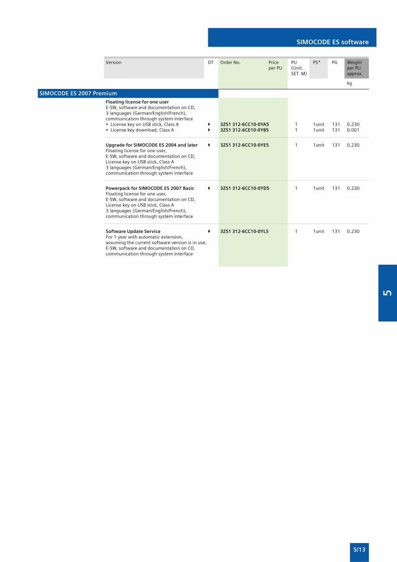
5
5/13
SIMOCODE ES software
Version DT Order No. Price PU PS* PG Weightper PU (Unit. per PU
SET. M) approx.
kg
Floating license for one userE-SW, software and documentation on CD,3 languages (German/English/French),communication through system interface• License key on USB stick, Class A 3ZS1 312-6CC10-0YA5 1 1unit 131 0.230• License key download, Class A 3ZS1 312-6CE10-0YB5 1 1unit 131 0.001
Upgrade for SIMOCODE ES 2004 and later 3ZS1 312-6CC10-0YE5 1 1unit 131 0.230Floating license for one user,E-SW, software and documentation on CD,License key on USB stick, Class A3 languages (German/English/French),communication through system interface
Powerpack for SIMOCODE ES 2007 Basic 3ZS1 312-6CC10-0YD5 1 1unit 131 0.230Floating license for one user,E-SW, software and documentation on CD,License key on USB stick, Class A3 languages (German/English/French),communication through system interface
Software Update Service 3ZS1 312-6CC10-0YL5 1 1unit 131 0.230For 1 year with automatic extension,assuming the current software version is in use,E-SW, software and documentation on CD.communication through system interface
SIMOCODE ES 2007 Premium

5
5/14
3RP15 timing relaysin industrial enclosure, 22.5 mm
Overview
Standards
The timing relays comply with:
• EN 60721-3-3 "Environmental conditions"
• EN 61812-1/DIN VDE 0435 Part 2021 "Electrical relays, timingrelays"
• EN 61000-6-2 and EN 61000-6-4 "Electromagneticcompatibility"
• EN 60947-5-1; (VDE 0660 Part 200) "Low-voltage controlgear"
Application
Timing relays are used in control, starting, and protective circuitsfor all switching operations involving time delays. They guaranteea high level of functionality and a high repeat accuracy of timersettings.
3RP Timing Relays
NSB0_01423b
LED for indicating"Timing relay on voltage"
LED for indicating"Relay switched"
Time setting range selector switch
Function switch
Device labeling plate
Operating timeadjustment
Inspection windowfor set time range
Inspection windowfor set function

5
5/15
Selection and ordering data
Solid-state timing relays for general use in control systems andmechanical engineering with:
• 1 Changeover contact or 2 changeover contacts
3RP15 timing relaysin industrial enclosure, 22.5 mm
• Single or selectable time setting rangers
• Switch position indication by LED
• Voltage indication by LED
Version Time setting Rated control DT Screw terminals PU PS* PG Weightrange t supply voltage Us (Unit. per PUadjustable by SET. M) approx.rotary switch to
AC 50/60 Hz DC Order No. PriceV V per PU kg
The functions can be adjusted by means of rotary switches. Insert labels can be used to adjust different functions of the 3RP15 05timing relay clearly and unmistakably. The corresponding labels can be ordered as an accessory.The same potential must be applied to terminals A. and B.1)
With LED and
1 CO contact,8 functions 1.5... 30 s 24 ... 2406) 24 ... 2403) 3RP15 05-1AW30 1 1 unit 101 0.136
With LED and 0.5 ... 10 s 24/100 ...127 24 3RP15 11-1AQ30 1 1 unit 101 0.1081 CO contact, 24/200 ... 240 24 3RP15 11-1AP30 1 1 unit 101 0.108
5 ... 100 s 24/100 ... 127 24 3RP15 13-1AQ30 1 1 unit 101 0.10724/200 ... 240 24 3RP15 13-1AP30 1 1 unit 101 0.108
With LED and
1 CO contact 0.05 ... 1 s 24/100 ... 127 24 3RP15 25-1AQ30 1 1 unit 101 0.1090.15 ... 3 s 24/200 ... 240 24 3RP15 25-1AP30 1 1 unit 101 0.1040.5 ... 10 s
2 CO contacts 1.5 ... 30 s0.05 ... 1 min 606)
5 ... 100 s0.15 ... 3 min0.5 ... 10 min 24 ... 2406) 24... 2403) 3RP15 25-1BW30 1 1 unit 101 0.1591.5 ... 30 min0.05 ... 1 h5 ... 100 min0.15 ... 3 h0.5 ... 10 h1.5 ... 30 h5 ... 100 h∞2)
3RP15 05 timing relays, multifunction, 15 time setting ranges
3RP15 1. timing relays, ON-delay, 1 time setting range
3RP15 25 timing relays, ON-delay, 15 time setting ranges
1) For functions, see 3RP 19 01-0. label set.2) With switch position ∞, no timing. For test purposes (ON/OFF function)
on site. Relay is constantly on when activated, or relay remainsconstantly off when activated. Depending on which function is set.
3) Operating range 0.7 ... 1.1 x Us.4) Positively driven: NO and NC are never closed simultaneously; contact
gap ≥ 0.5 mm is ensured, minimum make-break capacity 12 V, 3 mA.
5) The changeover contacts are actuated simultaneously, as a result ofwhich only 8 functions are selectable (no wye-delta, no instantaneouscontact).
6) Operating range 0.8 ... 1.1 x Us.
3RP Timing Relays
3RP 15 05-1BP30
3RP 15 05-1AP30
3RP 15 25-1BW30
* You can order this quantity or a multiple thereof.

5
5/16
Solid-state timing relays for general use in control systems andmechanical engineering with:
• 1 Changeover contact or 2 changeover contacts
3RP15 timing relaysin industrial enclosure, 22.5 mm
• Single or selectable time setting rangers
• Switch position indication by LED
• Voltage indication by LED
Version Time setting Rated control DT Screw terminals PU PS* PG Weightrange t supply voltage Us (Unit. per PUadjustable by SET. M) approx.rotary switch to
AC 50/60 Hz DC Order No. PriceV V per PU kg
With LED and 0.5 ... 10 s 24/100 ... 127 24 A 3RP15 31-1AQ30 1 1 unit 101 0.1401 CO contact, 24/200 ... 240 24 3RP15 31-1AP30 1 1 unit 101 0.140The samepotential mustbe applied toterminals A and B
5 ... 100 s 24/100 ... 127 24 A 3RP15 33-1AQ30 1 1 unit 101 0.13924/200 ... 240 24 3RP15 33-1AP30 1 1 unit 101 0.140
1 NO contactinstantaneous and1 NO contactdelayed 380 ...440
(common contactroot terminal 17)3 ... 60 s 24/100 ... 127 24 3RP15 76-1NQ30 1 1unit 101 0.112
24/200 ... 240 24 3RP15 76-1NP30 1 1 unit 101 0.113200 ... 240/380 ...440 -- B 3RP15 76-1NM20 1 1 unit 101 0.113
3RP15 05 timing relays, multifunction, 15 time setting ranges
3RP15 7. timing relays, wye-delta function6), dead interval 50 ms,1 time setting range
1) Setting of output contacts in as-supplied state not defined (bistablerelay). Application of the control voltage once results in contactchangeover to the correct setting.
2) Operating range 0.7 ... 1.25 x Us.
3) Operating range 0.85 ... 1.1 x Us.
4) With switch position •, no timing. For test purposes (ON/OFF function)on site. For dead time "infinite", the relay is always off. For pulse time"infinite", the relay is always on.
5) Operating range 0.8 ... 1.1 x Us.
3RP Timing Relays
* You can order this quantity or a multiple thereof.
3RP15 76-1NP30
3RP15 33-1AP30

5
5/17
3RP15 timing relaysin industrial enclosure, 22.5 mm
Accessories
Version Function Iden- Use DT Order No. Price PU PS* PG Weighttifica- per PU (Unit. per PUtion SET. M) approx.
Accessory for 3RP15 05 (not included in the scope of supply).The label set offers the possibility of labeling timing relays withthe set function in English and German.
1 label With ON-delay A for devices 3RP19 01-0A 1 5 units 101 0.003set (1 unit) OFF-delay with auxiliary voltage with 1 COwith ON-delay and OFF-delay with contact8 functions auxiliary voltage C and
Flashing, starting with interval D 3RP15 05-Passing make contact E RW30Passing break contact with Fauxiliary voltagePulse-forming with Gauxiliary voltageAdditive ON-delay with auxiliary Hvoltage
Push-In lugs for devices 3RP19 03 1 10units 101 0.002For screw mounting, with 1 or2 units are required for each device 2 CO
contacts
Label sets
Covers and push-in-lugs
3RP Timing Relays
* You can order this quantity or a multiple thereof.
3RP 19 01-0A
3RP 19 03

5
5/18
Line monitoring
Overview
Solid-state line monitoring relays provide maximum protectionfor mobile machines and plants or for unstable networks. Networkand voltage faults can be detected early and rectified before fargreater damage ensues.
Depending on the version, the relays monitor phase sequence,phase failure with and without N conductor monitoring, phaseunbalance, undervoltage or overvoltage.
Phase unbalanced is evaluated as the difference between thegreatest and the smallest phase voltage relative to the greatestphase voltage. Undervoltage or overvoltage exists when at leastone phase voltage deviates by 20 % from the set rated systemvoltage or the directly set limit values are overshot or undershot.The rms value of the voltage is measured.
The relays are used above all for mobile equipment, e.g. airconditioning compressors, refrigerating containers, building sitecompressors and cranes.
Function Application
Phase sequence • Direction of rotation of the operating mechanism
Phase failure • A fuse has tripped
• Failure of the control supply voltage
• Broken cable
Phase unbalance • Overheating of the motor due to asymmetricalvoltage
• Detection of asymmetrically loaded networks
Undervoltage • Increased current on a motor with correspondingoverheating
• Unintentional resetting of a device
• Network collapse, particularly with battery power
Overvoltage • Protection of a plant against destruction due toovervoltage
Application
Benefits
• Can be used without auxiliary voltage in any network from160 ... 600 V AC worldwide thanks to wide voltage range
• Variably adjustable to overvoltage, undervoltage or windowmonitoring
• Freely configurable delay times and reset response
• Width 22.5 mm
• Permanent display of ACTUAL value and network fault typeon the digital variants
• Automatic correction of the direction of rotation bydistinguishing between power system faults and wrong phasesequence
• All versions with removable terminals
• All versions with screw terminals or alternatively withinnovative spring-loaded terminals
3UG Monitoring Relays for Electrical and Additional Measurements
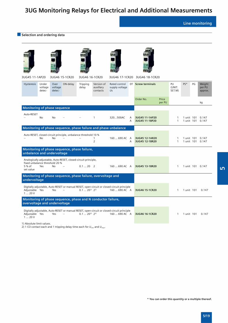
5
5/19
Line monitoring
Selection and ordering data
Hysteresis Under Over ON-delay Tripping Version of Rated control DT Screw terminals PU PS* PG Weightvoltage voltage delay auxillary supply voltage (UNIT. per PUdetec- detec- contacts Us SET.M) approx.
Order No. Priceper PU kg
Auto-RESET-- No No -- -- 1 320...500AC A 3UG45 11-1AP20 1 1 unit 101 0.147
A 3UG45 11-1BP20 1 1 unit 101 0.147
Auto-RESET, closed-circuit principle, unbalance threshold 10 %-- No No -- -- 1 160 … 690 AC A 3UG45 12-1AR20 1 1 unit 101 0.147
2 A 3UG45 12-1BR20 1 1 unit 101 0.147
Analogically adjustable, Auto-RESET, closed-circuit principle,fixed unbalance threshold 20 %5 % of Yes No -- 0.1 ... 20 2 160 … 690 AC A 3UG45 13-1BR20 1 1 unit 101 0.147set value
Digitally adjustable, Auto-RESET or manual RESET, open-circuit or closed-circuit principleAdjustable Yes Yes -- 0.1 … 202) 22) 160 … 690 AC A 3UG46 15-1CR20 1 1 unit 101 0.1471 ... 20 V
Digitally adjustable, Auto-RESET or manual RESET, open-circuit or closed-circuit principleAdjustable Yes Yes -- 0.1 … 202) 22) 160 … 690 AC A 3UG46 16-1CR20 1 1 unit 101 0.1471 ... 20 V
1) Absolute limit values.2) 1 CO contact each and 1 tripping delay time each for Umin and Umax.
Monitoring of phase sequence
Monitoring of phase sequence, phase failure and phase unbalance
Monitoring of phase sequence, phase failure,unbalance and undervoltage
Monitoring of phase sequence, phase failure, overvoltage andundervoltage
Monitoring of phase sequence, phase and N conductor failure,overvoltage and undervoltage
3UG Monitoring Relays for Electrical and Additional Measurements
* You can order this quantity or a multiple thereof.
3UG45 11-1AP20 3UG46 15-1CR20 3UG46 16-1CR20 3UG46 17-1CR20 3UG46 18-1CR20

5
5/20
Power factor and active current monitoring
Overview
The 3UG46 41 power factor and active current monitoring deviceenables the load monitoring of motors.
Whereas power factor monitoring is used above all for monitoringno-load operation, the active current monitoring option can beused to observe and evaluate the load factor over the entire torquerange.
Application
Benefits
• Can be used world-wide thanks to wide voltage range from90 ... 690 V1)
• Monitoring of even small single-phase motors with a no-loadsupply current below 0.5 A
• Simple determination of threshold values through the directcollection of measured variables on motor loading
• Window monitoring and active current measurement enabledetection of cable breaks between control cabinets andmotors, as well as phase failures
• Power factor or active current can be selected as measurementprinciple
1) Absolute limit values.
• No-load monitoring and load shedding, such as in the eventof a V-belt tear
• Underload monitoring in the low performance range,e.g. in the event of pump no-load operation
• Monitoring of overload, e.g. due to a dirty filter system
• Simple power factor monitoring in networks for control ofcompensation equipment
• Broken cable between control cabinet and motor
3UG Monitoring Relays for Electrical and Additional Measurements

5
5/21
Power factor and active current monitoring
Selection and ordering data
Measuring range Hystersis ON-delay OFF-delay Rated control DT Screw terminals PU PS* PG Weightsupply (UNIT. per PUvoltageUs1) SET.M) approx.
For For For For AC 50/60 Hzpower active power activefactor current factor current
I res
Order No. Price
p.f. A p.f. A s s V per PU kg
0.10 ... 0.99 0.2 ... 10.0 0.1 0.1 ... 2.0 0 ... 99 0.1 ... 20.0 90 ... 690 A 3UG46 41-1CS20 1 1 unit 101 0.147
Relay for monitoring the power factor and the active current(p.f. x Ires),
overshoot, undershoot or window monitoring,
single and three-phase, overall width 22.5 mm
Digitally adjustable, with LCD display
• Upper and lower threshold value can be adjusted separately
• 1 changeover contact each for undershoot/overshoot
• Permanent display of actual value and tripping state
3UG Monitoring Relays for Electrical and Additional Measurements

5
5/22
Residual-current monitoringsummation current transformers
Overview
The 3UG46 24 residual-current monitoring relay is used togetherwith the 3UL22 summation current transformer for plantmonitoring.
Application
Selection and ordering data
Residual-current monitoring relaysStandard rail mountingWidth 22.5 mmRelay for monitoring residual currents for 3UL22 summationcurrent transformers with rated residual current IDn 0.3 ... 40 A
• Digitally adjustable with three buttons, illuminated LCD
• Adjustable limit value and warning threshold
• Permanent display of actual value and tripping state
• 1 CO contact each for limit violation and warning threshold
• Plant monitoring
Display Setting Hystersis ON / Rated control DT Screw terminals PU PS* PG Weightrange range Limit value Warning tripping supply (UNIT. per PU
value delay voltageUs1) SET.M) approx.time Order No. Price
A A A A s V per PU kg
10...120 % 10 ... 100 % LSB1) up to 5 % 0.1 ... 20 90 ... 690 A 3UG46 24-1CS20 1 1 unit 101 0.147of IΔn of IΔn 50% of IΔn of IΔn
3UG Monitoring Relays for Electrical and Additional Measurements

5
5/23
Residual-current monitoringsummation current transformers
Overview
The 3UL22 summation current transformers sense fault currentsin machines and plants. Together with the 3UG46 24 residual-current monitoring relay or the SIMOCODE 3UF motormanagement and control device they enable residual-current andground-fault monitoring.
Application
Selection and ordering data
• Plant monitoring
Summation current transformers(essential accessory for 3UG46 24 or SIMOCODE 3UF)
3UG Monitoring Relays for Electrical and Additional Measurements
3UL22
Feed-through Rated insulation Rated fault DT Screw terminals PU PS* PG WeightOpening voltageUs current IΔn (UNIT. per PUdiameter SET.M) approx.
Order No. Pricemm V A per PU kg
40 690 0.3 B 3UL22 01-1A 1 1 unit 101 0.5710.5 B 3UL22 01-2A 1 1 unit 101 0.4081 C 3UL22 01-3A 1 1 unit 101 0.324
65 690 0.3 B 3UL22 02-1A 1 1 unit 101 0.9000.5 B 3UL22 02-2A 1 1 unit 101 0.713
1 B 3UL22 02-3A 1 1 unit 101 0.5686 C 3UL22 02-1B 1 1 unit 101 0.56110 C 3UL22 02-2B 1 1 unit 101 0.56316 C 3UL22 02-3B 1 1 unit 101 0.57325 C 3UL22 02-4B 1 1 unit 101 0.57540 C 3UL22 02-5B 1 1 unit 101 0.564
120 1000 0.3 B 3UL22 03-1A 1 1 unit 101 3.4350.5 B 3UL22 03-2A 1 1 unit 101 2.8101 B 3UL22 03-3A 1 1 unit 101 1.9656 C 3UL22 03-1B 1 1 unit 101 1.95510 C 3UL22 03-2B 1 1 unit 101 1.99016 C 3UL22 03-3B 1 1 unit 101 1.91725 C 3UL22 03-4B 1 1 unit 101 1.85140 C 3UL22 03-5B 1 1 unit 101 1.905
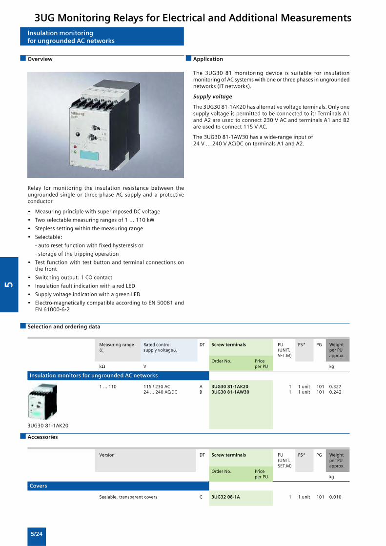
5
5/24
Covers
Insulation monitoringfor ungrounded AC networks
Overview
Relay for monitoring the insulation resistance between theungrounded single or three-phase AC supply and a protectiveconductor
• Measuring principle with superimposed DC voltage
• Two selectable measuring ranges of 1 ... 110 kW
• Stepless setting within the measuring range
• Selectable:
- auto reset function with fixed hysteresis or
- storage of the tripping operation
• Test function with test button and terminal connections onthe front
• Switching output: 1 CO contact
• Insulation fault indication with a red LED
• Supply voltage indication with a green LED
• Electro-magnetically compatible according to EN 50081 andEN 61000-6-2
Application
Selection and ordering data
The 3UG30 81 monitoring device is suitable for insulationmonitoring of AC systems with one or three phases in ungroundednetworks (IT networks).
Supply voltage
The 3UG30 81-1AK20 has alternative voltage terminals. Only onesupply voltage is permitted to be connected to it! Terminals A1and A2 are used to connect 230 V AC and terminals A1 and B2are used to connect 115 V AC.
The 3UG30 81-1AW30 has a wide-range input of24 V ... 240 V AC/DC on terminals A1 and A2.
Insulation monitors for ungrounded AC networks
Accessories
3UG Monitoring Relays for Electrical and Additional Measurements
3UG30 81-1AK20
Measuring range Rated control DT Screw terminals PU PS* PG WeightUs supply voltageUs (UNIT. per PU
SET.M) approx.Order No. Price
kΩ V per PU kg
1 ... 110 115 / 230 AC A 3UG30 81-1AK20 1 1 unit 101 0.32724 ... 240 AC/DC B 3UG30 81-1AW30 1 1 unit 101 0.242
Version DT Screw terminals PU PS* PG Weight(UNIT. per PUSET.M) approx.
Order No. Priceper PU kg
Sealable, transparent covers C 3UG32 08-1A 1 1 unit 101 0.010
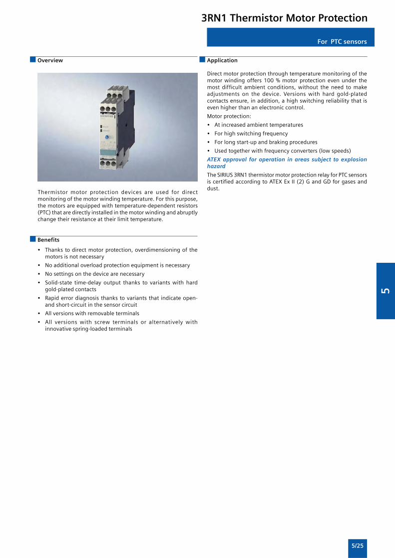
5
5/25
For PTC sensors
Overview
Thermistor motor protection devices are used for directmonitoring of the motor winding temperature. For this purpose,the motors are equipped with temperature-dependent resistors(PTC) that are directly installed in the motor winding and abruptlychange their resistance at their limit temperature.
Application
Benefits
• Thanks to direct motor protection, overdimensioning of themotors is not necessary
• No additional overload protection equipment is necessary
• No settings on the device are necessary
• Solid-state time-delay output thanks to variants with hardgold-plated contacts
• Rapid error diagnosis thanks to variants that indicate open-and short-circuit in the sensor circuit
• All versions with removable terminals
• All versions with screw terminals or alternatively withinnovative spring-loaded terminals
Direct motor protection through temperature monitoring of themotor winding offers 100 % motor protection even under themost difficult ambient conditions, without the need to makeadjustments on the device. Versions with hard gold-platedcontacts ensure, in addition, a high switching reliability that iseven higher than an electronic control.
Motor protection:
• At increased ambient temperatures
• For high switching frequency
• For long start-up and braking procedures
• Used together with frequency converters (low speeds)
ATEX approval for operation in areas subject to explosionhazard
The SIRIUS 3RN1 thermistor motor protection relay for PTC sensorsis certified according to ATEX Ex II (2) G and GD for gases anddust.
3RN1 Thermistor Motor Protection

5
5/26
For PTC sensors
Selection and ordering data
Thermistor motor protection relays for PTC thermistors (Type A PTCs)• 3RN10 13-.BW01: bistable version, does not trigger in the
event of control supply voltage failure
• All devices except for 24V AC/DC feature electrical isolation
Solid-state timing relays for general use in control systems andMonostable version with closed-circuit principle, triggers in theevent of control supply voltage failure
PTB01 ATEX approval
RESET Contacts Rated control DT Screw terminals PU PS* PG Weightsupply voltage Us (Unit. per PU50/60 Hz SET. M) approx.
Order No. PriceV per PU kg
Terminal A1 is jumpered with the root of thechangeover contact
Auto 1 CO 24 AC/DC 3RN10 00-1AB00 1 1 unit 101 0.114110 AC A 3RN10 00-1AG00 1 1 unit 101 0.157230 AC 3RN10 00-1AM00 1 1 unit 101 0.156
3RN1 Thermistor Motor Protection
Compact signal evaluation units, width 22.5 mm, 1 LED

5
5/27
For PTC sensors
Accessories
3RN1 Thermistor Motor Protection
Blank labels
Push-in lugs
Use Version DT Order No. Price PU PS* PG Weightper PU (Unit. per PU
SET. M) approx.
kg
Blank labels, 20 mm x 7 mm, C 3RT19 00-1SB20 100 340 101 22.000pastel turquoise1) units
For devices Push-In lugs 3RP19 03 1 10 101 0.002with 1 or 2 For screw mounting, unitsCOcontacts 2 uits are requiredfor each device
3RP19 03

5
5/28
General Data
Overview
SIRIUS safety relays are the key elements of a consistent andcost-effective safety chain. Be it EMERGENCY-STOP disconnection,protective door monitoring or the protection of presses orpunches – with SIRIUS safety relays every safety application canbe implemented to optimum effect in terms of engineering andprice.
SIRIUS safety relays provide numerous safety-related functions:
• Monitoring the safety functions of sensors• Monitoring the sensor cables• Monitoring the correct operation of the safety relay• Monitoring the actuators (contactors) in the shutdown circuit• Safety-oriented disconnection when dangers arise
SIRIUS safety relays meet the highest requirements (Category 4)according to EN 954-1 and achieve the highest safety integritylevel (SIL 3) according to IEC 61508.
Benefits
Application
SIRIUS safety relays are used mainly in autonomous safetyapplications which are not connected to a safety-oriented bussystem. Their function here is to evaluate the sensors and thesafety-oriented shutdown of hazards. Also they check and monitorthe sensors, actuators and safety-oriented functions of the safetyrelay.
General
• Can be used for all safety applications thanks to compliancewith the highest safety standards (Category 4 according toEN 954-1 or SIL 3 according to IEC 61508)
• Suitable for use all over the world through compliance withall globally established certifications
• Compact, service-proven SIRIUS design creates more space inthe control cabinet
• Flexible connectability and expendability make subsequentchanges easy
• Removable terminals for greater plant availability• Yellow front plate clearly identifies the device as an item of
safety equipment• Sensor cable up to 2000 m long enables use in large-scale
plants
Relay outputs
• Different voltages can be switched through the floatingcontacts
• Higher currents can be switched with relay contacts
Solid-state outputs
• Wear-free• Suitable for operation in fast switching applications• Insensitive to vibrations and dirt• Good electrical endurance
Microprocessor systems
• Flexible use thanks to many different integrated functions• Easy parameterization using DIP switches on the front• High functional reliability based on extensive monitoring
functions• Operated by the machine control• Also connection of non-contact sensors (light arrays, light
barriers etc.)
3TK28 Safety Relays

5
5/29
with electronic enabling circuits
Selection and ordering data
Type 3TK28 40 3TK28 41 3TK28 42 3TK28 45Basic units Basic units Basic units Multi- Multi- Multi- Multi- Multi- Multi- Multi- Multi-
function function function function function function function functionunit "automatic andmonitoredstart"
tv tv tv tv tv tv
Sensors• Input 1 1 1 2 2 2 2 2 2 2 2
• Solid-state --
• With contacts
Safety mats -- -- -- -- --
Start
• Auto 1 1 -- -- 1 1 -- --
• Monitored 1 1 2 2 1 1 2 2
Cascading Input24 V DC --
Key-operated switches -- -- --
Enabling circuit, floating
• Stop category 0 -- -- -- 2NO 1NO 2NO 1NO 2NO 1NO 1NO 1NO
• Stop category 1 -- -- -- -- 1NO -- 1NO -- 1NO 1NO 1NO
Enabling circuit,solid-state
• Stop category 0 21) 2 1 2 1 2 1 2 1 1 1
• Stop category 1 -- -- 1 -- 1 -- 1 -- 1 1 1
Signalling outputs• Floating -- -- -- -- -- -- -- -- -- -- --
• Solid-state -- -- -- 1 1 1 1 1 1 1 1
Categoryaccording to 3 4 4 4 4 4 4 4 4 4 4EN 954-1 max
SIL level max. 2 3 3 3 3 3 3 3 3 3 3
Performance level PLaccoring to d e e e e e e e e e eEN ISO 13849
Rated control supplyvoltage 24 V DC
= Available-- = Not available
1) The outputs are only safe when an external contactor is used.
3TK28 Safety Relays

5
5/30
with electronic enabling circuits
3TK28 Safety Relays
3TK28 41-1BB40
3TK28 42-1BB41
3TK28 45-1HB40
Rated control OFF-delay DT Screw terminals PU PS* PG Weightsupply voltage Us tv (Unit. per PU
SET. M) approx.Order No. Price
V s per PU kg
Rated control supply voltage Us 24 V DC
3TK28 40 basic units24 DC -- A 3TK28 40-1BB40 1 1 unit 102 0.180
3TK28 41 basic units24 DC -- A 3TK28 41-1BB40 1 1 unit 102 0.166
3TK28 42 basic units tv24 DC 0.05 ... 3 A 3TK28 42-1BB41 1 1 unit 102 0.168
0.5 ... 30 A 3TK28 42-1BB42 1 1 unit 102 0.1665 ... 300 A 3TK28 42-1BB44 1 1 unit 102 0.166
3TK28 45 multi-function units"automatic and monitored start"24 DC -- A 3TK28 45-1HB40 1 1 unit 102 0.350
3TK28 45 multi-function units tv"automatic and monitored start"24 DC 0.05 ... 3 A 3TK28 45-1HB41 1 1 unit 102 0.350
0.5 ... 30 A 3TK28 45-1HB42 1 1 unit 102 0.3505 ... 300 A 3TK28 45-1HB44 1 1 unit 102 0.350
3TK28 45 multi-function units"monitored start"24 DC -- A 3TK28 45-1DB40 1 1 unit 102 0.350

5
5/31
3TK28 45-1HB41
3TK28 45-1DB40
3TK28 45-1DB41
Rated control OFF-delay DT Screw terminals PU PS* PG Weightsupply voltage Us tv (Unit. per PU
SET. M) approx.Order No. Price
V s per PU kg
Rated control supply voltage Us 24 V DC
3TK28 45 multi-function units tv"monitored start"24 DC 0.05 ... 3 A 3TK28 45-1DB41 1 1 unit 102 0.350
0.5 ... 30 A 3TK28 45-1DB42 1 1 unit 102 0.3505 ... 300 A 3TK28 45-1DB44 1 1 unit 102 0.350
3TK28 45 multi-function units"OK button"24 DC -- A 3TK28 45-1EB40 1 1 unit 102 0.350
3TK28 45 multi-function units tv"OK button"24 DC 0.05 ... 3 A 3TK28 45-1EB41 1 1 unit 102 0.350
0.5 ... 30 A 3TK28 45-1EB42 1 1 unit 102 0.3505 ... 300 A 3TK28 45-1EB44 1 1 unit 102 0.350
3TK28 45 multi-function units tv"spring-locked tumbler"24 DC 0.05 ... 3 A 3TK28 45-1FB41 1 1 unit 102 0.350
0.5 ... 30 A 3TK28 45-1FB42 1 1 unit 102 0.3505 ... 300 A 3TK28 45-1FB44 1 1 unit 102 0.350
3TK28 45 multi-function units tv"magnet-locked tumbler"24 DC 0.05 ... 3 A 3TK28 45-1GB41 1 1 unit 102 0.350
0.5 ... 30 A 3TK28 45-1GB42 1 1 unit 102 0.3505 ... 300 A 3TK28 45-1GB44 1 1 unit 102 0.350
with electronic enabling circuits
3TK28 Safety Relays

5
5/32
with electronic enabling circuits
Selection and ordering data
Type 3TK28 21 3TK28 22 3TK28 23 3TK28 24 3TK28 25 3TK28 26Basic units Basic units Basic units Basic units Basic units Basic units Basic units
24 V DC Wide voltagerange
Sensors• Input 1 1 1 1 1 1 1
• Solid-state -- -- -- -- --
• With contacts 1)
Safety mats -- -- -- -- --
Start• Auto --
• Monitored -- -- --
Cascading Input24 V DC -- -- -- -- --
Key-operated switches -- -- -- -- -- -- --
Enabling circuit, floating
• Stop category 0 3 NO 2 NO 2 NO 2NO 3 NO 4 NO 4NO
• Stop category 1 -- -- -- -- -- -- --
Enabling circuit,solid-state
• Stop category 0 -- -- -- -- -- -- --
• Stop category 1 -- -- -- -- -- -- --
Signalling outputs
• Floating 1 NC -- -- -- 2 NC 1 NC 1 NO + 1 NC
• Solid-state -- -- -- -- -- 2 --
Category according toEN 954-1 max 32) 4 4 32) 4 4 4
SIL level max. 2 3 3 2 3 3 3
Performance level PLaccoring to -- -- -- -- -- e eEN ISO 13849
Rated control supplyvoltage• 24 V DC -- -- -- --
• 24 V AC/DC -- -- --
• 24 V AC -- -- -- -- -- --
• 115 V AC -- -- -- -- --
• 230 V AC -- -- -- -- --
• 24...240 V AC/DC -- -- -- -- -- --
= Available-- = Not available
1) The ON button is not monitored.2) Depending on the hazard assessment, additional measures may
be necessary in the sensor circuit (e.g. protected laying).
3TK28 Safety Relays

5
5/33
with relay enabling circuits
Selection and ordering data
Type 3TK28 27 3TK28 28 3TK28 30 3TK28 34 3TK28 35Basic units Basic units Expansion units2) Two-hand control units Slowing down test
apparatustv tv
Sensors• Input 1 1 -- 1 --
• Solid-state -- -- -- -- --
• With contacts -- --
Safety mats -- -- -- -- --
Start• Auto -- -- -- --
• Monitored -- -- -- --
Cascading Input24 V DC -- -- -- -- --
Key-operated switches -- -- -- -- --
Enabling circuit, floating
• Stop category 0 2 NO 2 NO 4 NO 2NO+2NC 3 NO+2NC
• Stop category 1 2 NO 2 NO -- -- --
Enabling circuit,solid-state
• Stop category 0 -- -- -- -- --
• Stop category 1 -- -- -- -- --
Signalling outputs
• Floating 1NC 1NC -- 2 --
• Solid-state -- -- -- -- --
Category according toEN 954-1 max 41) 41) As basic unit 4 4
SIL level max. 3 3 As basic unit 3 3
Performance level PLaccoring to -- -- -- -- --EN ISO 13849
Rated control supplyvoltage• 24 V DC --
• 24 V AC/DC -- -- -- --
• 24 V AC --
• 115 V AC
• 230 V AC
• 24...240 V AC/DC -- -- -- -- --
= Available-- = Not available
1) Only possible for instantaneous enabling contacts, otherwise Category 3.2) For expansion of Siemens safety products.
3TK28 Safety Relays

5
5/34
with relay enabling circuits
3TK28 Safety Relays
Rated control supply voltages Us24 V DC and 50/60 Hz, 24, 115, 230 V AC
Rated control OFF-delay DT Screw terminals PU PS* PG Weightsupply voltage Us tv (Unit. per PU
SET. M) approx.Order No. Price
V s per PU kg
3TK28 21 basic units24 AC/DC -- 3TK28 21-1CB30 1 1 unit 102 0.276
3TK28 22 basic units24 AC/DC -- 3TK28 22-1CB30 1 1 unit 102 0.271
3TK28 23 basic units24 AC/DC -- 3TK28 23-1CB30 1 1 unit 102 0.271
3TK28 24 basic units24 AC/DC -- 3TK28 24-1CB30 1 1 unit 102 0.25424 DC -- 3TK28 24-1BB40 1 1 unit 102 0.249115 AC -- A 3TK28 24-1AJ20 1 1 unit 102 0.294230 AC -- 3TK28 24-1AL20 1 1 unit 102 0.288
3TK28 25 basic units24 DC -- 3TK28 25-1BB40 1 1 unit 102 0.42324 AC -- A 3TK28 25-1AB20 1 1 unit 102 0.421115 AC -- 3TK28 25-1AJ20 1 1 unit 102 0.519230 AC -- 3TK28 25-1AL20 1 1 unit 102 0.516
3TK28 26 basic unit24 DC -- 3TK28 26-1BB40 1 1 unit 102 0.37024 ... 240 AC/DC -- 3TK28 26-1CW30 1 1 unit 102 0.400
3TK28 27 basic units tv24 DC 0.05 ... 3 3TK28 27-1BB41 1 1 unit 102 0.49524 AC B 3TK28 27-1AB21 1 1 unit 102 0.499115 AC B 3TK28 27-1AJ21 1 1 unit 102 0.650230 AC A 3TK28 27-1AL21 1 1 unit 102 0.65024 DC 0.5 ... 30 3TK28 27-1BB40 1 1 unit 102 0.49724 AC A 3TK28 27-1AB20 1 1 unit 102 0.496115 AC 3TK28 27-1AJ20 1 1 unit 102 0.650230 AC 3TK28 27-1AL20 1 1 unit 102 0.650
3TK28 28 basic units tv24 DC 0.05 ... 3 3TK28 28-1BB41 1 1 unit 102 0.49924 AC B 3TK28 28-1AB21 1 1 unit 102 0.501115 AC B 3TK28 28-1AJ21 1 1 unit 102 0.657230 AC A 3TK28 28-1AL21 1 1 unit 102 0.65024 DC 0.5 ... 30 3TK28 28-1BB40 1 1 unit 102 0.49624 AC B 3TK28 28-1AB20 1 1 unit 102 0.500115 AC A 3TK28 28-1AJ20 1 1 unit 102 0.650230 AC A 3TK28 28-1AL20 1 1 unit 102 0.650
3TK28 30 expansion units24 AC/DC -- 3TK28 30-1CB30 1 1 unit 102 0.267115 AC A 3TK28 30-1AJ20 1 1 unit 102 0.306230 AC A 3TK28 30-1AL20 1 1 unit 102 0.306
3TK28 34 two-hand control units24 DC -- 3TK28 34-1BB40 1 1 unit 102 0.43224 AC A 3TK28 34-1AB20 1 1 unit 102 0.424115 AC A 3TK28 34-1AJ20 1 1 unit 102 0.519230 AC A 3TK28 34-1AL20 1 1 unit 102 0.519
3TK28 35 slowing down test apparatus24 DC -- B 3TK28 35-1BB40 1 1 unit 102 0.495115 AC -- B 3TK28 35-1AJ20 1 1 unit 102 0.572230 AC -- B 3TK28 35-1AL20 1 1 unit 102 0.574
3TK28 21-1CB30
3TK28 25-1BB40
3TK28 26-1BB40
3TK28 27-1BB41
3TK28 30-1CB30

5
5/35
with contactor relay enabling circuits
Selection and ordering data
Type 3TK28 50 3TK28 51 3TK28 52 3TK28 53 3TK28 56 3TK28 56Basic units Basic units Basic units Basic units Expansion units 1) Expansion units 1)
tv
Sensors• Input 1 1 1 1 -- --
• Solid-state -- -- -- -- --
• With contacts -- --
Safety mats -- --
Start• Auto -- --
• Monitored -- --
Cascading Input24 V DC -- -- --
Key-operated switches -- -- -- -- --
Enabling circuit, floating
• Stop category 0 3 NO 2 NO 6 NO 3 NO 6 NO --
• Stop category 1 -- -- -- -- -- 3 NO
Enabling circuit,solid-state
• Stop category 0 -- -- -- 1 1 1
• Stop category 1 -- -- -- -- -- --
Signalling outputs
• Floating -- 1NC 1NC -- 1NC --
• Solid-state -- -- -- -- --
Category according to Corresponds to Corresponds toEN 954-1 max 3 3 3 4 basic unit basic unit
SIL level max. 2 2 2 3 3 3
Performance level PLaccoring to d d d e e eEN ISO 13849
Rated control supplyvoltage• 24 V DC
• 24 V AC/DC -- -- -- -- -- --
• 24 V AC -- -- -- --
• 115 V AC -- -- -- --
• 230 V AC -- -- --
• 24...240 V AC/DC -- -- -- -- -- --
Rated operational voltage
24 V DC
230 V AC
600 V AC
Switching capacity
AC-15 at U = 230 V
DC-13 at U = 24 V
= Available-- = Not available
1) For expansion of Siemens safety products.
3TK28 Safety Relays

5
5/36
with contactor relay enabling circuits
Rated control supply voltages Us
24 V DC and 50/60 Hz, 115, 230 V AC
3TK28 Safety Relays
Rated control supply voltages Us24 V DC and 50/60 Hz, 115, 230 V AC
Rated control OFF-delay DT Screw terminals PU PS* PG Weightsupply voltage Us tv (Unit. per PU
SET. M) approx.Order No. Price
V s per PU kg
3TK28 50 basic units24 DC -- A 3TK28 50-1BB40 1 1 unit 102 0.819115 AC B 3TK28 50-1AJ20 1 1 unit 102 0.765230 AC B 3TK28 50-1AL20 1 1 unit 102 0.770
3TK28 51 basic units24 DC -- B 3TK28 51-1BB40 1 1 unit 102 0.821115 AC B 3TK28 51-1AJ20 1 1 unit 102 0.770230 AC B 3TK28 51-1AL20 1 1 unit 102 0.767
3TK28 52 basic units24 DC -- A 3TK28 52-1BB40 1 1 unit 102 0.919230 AC B 3TK28 52-1AL20 1 1 unit 102 0.870
3TK28 53 basic units24 DC -- A 3TK28 53-1BB40 1 1 unit 102 0.714
3TK28 56 expansion units24 DC -- B 3TK28 56-1BB40 1 1 unit 102 0.785
3TK28 57 expansion units tv
24 DC 0.05 ... 3 B 3TK28 57-1BB41 1 1 unit 102 0.68224 DC 0.5 ... 30 B 3TK28 57-1BB42 1 1 unit 102 0.67924 DC 5 ... 300 B 3TK28 57-1BB44 1 1 unit 102 0.684

5
5/37
With special functions
Selection and ordering data
Type 3TK28 10Stoppage monitors
Sensors
• Input 3
• Solid-state --
• With contacts --
• Without sensors 3(measuring inputs)
Safety mats --
Start• Auto
• Monitored --
Cascading Input24 V DC --
Key-operated switches --
Enabling circuit, floating
• Stop category 0 3 NO + 1 NO
• Stop category 1 --
Enabling circuit,solid-state
• Stop category 0 --
• Stop category 1 --
Signalling outputs
• Floating 1 CO
• Solid-state 2
Category according toEN 954-1 max 4
SIL level max. 3
Performance level PLaccoring to --EN ISO 13849
Rated control supplyvoltage• 24 V DC
• 230 V AC
• 400 V AC/DC
= Available-- = Not available
3TK28 Safety Relays

5
5/38
With special functions
Rated control OFF-delay DT Screw terminals PU PS* PG Weightsupply voltage Us tv (Unit. per PU
SET. M) approx.Order No. Price
V s per PU kg
3TK28 10 stoppage monitors24 DC 0.2... 6 A 3TK28 10-0BA01 1 1 unit 102 0.500230 AC A 3TK28 10-0GA01 1 1 unit 102 0.500400 AC A 3TK28 10-0JA01 1 1 unit 102 0.500
Rated control supply voltages Us24 V DC and 50/60 Hz, 230, 400 V AC
3TK28 Safety Relays
3TK28 10-0BA01

Monitoring andControl Devices
SIMOCODE 3UF Motor Managementand Control Devices
5a/2 SIMOCODE pro 3UF7
motor management and control devices
3RP, 3RT19 Timing Relays
5a/23 General data
5a/27 3RP 15 timing relays in industrialenclousure, 22.5mm
Monitoring Relays
3UG Monitoring Relays
for Electrical and Additional Measurements
5a/33 Line monitoring
5a/38 Power factor and active currentmonitoring
Residual Current Monitoring
5a/43 - Residual-current monitoring relays
5a/48 - Summation current transformers
Insulation monitoring
5a/49 - for ungrounded AC networks
3RN1 Thermistor Motor Protection
5a/51 For PTC sensors
3TK28 Safety Relays
5a/57 General data
5a/59 With relay enabling circuits
5a/72 With contactor relay enabling circuits
5a/77 With special functions
5a

5a
5a/2
SIMOCODE pro 3UF7 motor managementand control devices
Overview
SIMOCODE pro V with current/voltage measuring module,expansion modules and operator panel with display
SIMOCODE pro is a flexible, modular motor management systemfor constant speed motors in the low-voltage range. It optimizesthe connection between instunmentation & control and motorfeeder. It increases plant availability and allows significant savingsto be made for start-up, operation and maintenance of a system.
When SIMOCODE pro is installed in the low-voltage switchboard,it is the intelligent interface between the higher-level automationsystem and the motor feeder and includes the following:
• Multifunctional, solid-state full motor protection which isindependent of the automation system
• Flexible software instead of hardware for the motor control• Detailed operating, service and diagnostics data• Open communication through PROFIBUS DP, the standard for
fieldbus systems
SIMOCODE ES is the software package for SIMOCODEproparameterization, start-up and diagnostics.
Design
General
SIMOCODE pro is a modularly constructed motor managementsystem which is subdivided into two device series with differentfunctional scopes:
• SIMOCODE pro C and
• SIMOCODE pro V.
Both series (systems) are made up of different hardware
components (modules):
System SIMOCODE pro C SIMOCODE pro V
Modules • Basic unit 1 • Basic unit 2Current measuring Current measuring module ormodule current/voltage measuring
module• Operator panel • Decoupling module
(optional) (optional)• Operator panel or operator
panel with display (optional)• Expansion modules
(optional)
Each feeder always comprises of one basic unit and one separatecurrent measuring module. The two modules are connectedtogether electrically through the system interface with aconnection cable and can be mounted mechanically connectedas a unit (one behind the other) or separately (side by side). Themotor current to be monitored is used only for choosing thecurrent measuring module.
An optional operator panel for mounting in the control cabinetdoor can be connect through a second system interface on thebasic unit. Both the current measuring module and the operatorpanel are electrically supplied by the basic unit through theconnection cable. More inputs, outputs and functions can beadded to basic unit 2 (SIMOCODE pro V) by means of optionalexpansion modules, thus supplementing the inputs and outputsalready existing on the basic unit.
All modules are connected by connection cables. The connectioncables are available in various lengths. The maximum distancebetween the modules (e.g. between the basic unit and the currentmeasuring module) must not exceed 2.5 m. The total length ofall the connection cables in a single system must not be morethan 3 m.
SIMOCODE pro designed for mixed operation
Depending on functional requirements, the two systemsSIMOCODE pro V & pro can be used simultaneously without anyproblems and without any additional outlay in a low-voltagesystem. SIMOCODE pro C is fully upward-compatible to SIMOCODEpro V. The same components are used. The parameterization ofSIMOCODE pro C can be transferred without any problems. Bothsystems have the same removable terminals and the sameterminal designations.

5a
5a/3
SIMOCODE pro 3UF7 motor managementand control devices
Monitoring and Control Devices
SIMOCODE pro C, basic unit 1
The compact system for
• Direct-on-line and reversing starters
• For actuation of a circuit breaker (MCCB)
with up to 4 binary inputs, up to 3 monostable relay outputs andone thermistor connection (binary PTC)
The basic unit 1 is available in two different versions for thefollowing supply voltages:
• 24 V DC
• 110 ... 240 V AC/DC
SIMOCODE pro V, basic unit 2
The variable system offers all SIMOCODE pro C functions plusmany additional functions. Basic unit 2 supports the followingcontrol functions:
• Direct-on-line and reversing starters
• Wye/delta starters, also with direction reversal
• Two speeds, motors with separate windings
(pole-changing switch); also with direction reversal
• Two speeds, motors with separate Dahlander windings
(also with direction reversal)
• Positioner actuation
• Solenoid valve actuation
• Actuation of a circuit breaker (MCCB)
• Soft starter actuation (also with direction reversal)
Basic unit 2 has 4 binary inputs, 3 monostable relay outputs andone thermistor connection (binary PTC). The type and number ofinputs and outputs can be increased by means of additionalexpansion modules.
Basic unit 2 is available in two different versions for the followingsupply voltages:
• 24 V DC
• 110 ... 240 V AC/DC
SIMOCODE pro C, basic unit 1
Inputs:4 binary inputs, with internal supply from 24 V DC
Outputs:3 (2+1) monostable relay outputs
Thermistor connection for binary PTC
PROFIBUS interface:• 9-pole SUB-D or• Terminal connection
Connection of the supply voltage:• 24 V DC or• 110 ... 240 V AC/DC
Test/Reset button
3 LEDs
• 2 system interfaces for connecting• A current measuring module and• An operator panel
Basic unit 1 is suitable for standard rail mounting with additionalpush-in lugs it is also suitable for fixing to a mounting plate.
SIMOCODE pro V, basic unit 2
Inputs:4 binary inputs, with internal supply from 24 V DC
Outputs:3 (2+1) monostable relay outputs
Thermistor connection for binary PTC
PROFIBUS interface:9-pole SUB-D orTerminal connection
Connection of the supply voltage:24 V DC or110 ... 240 V AC/DC
Test/Reset button
3 LEDs
2 system interfaces for connecting• A current measuring module or current/voltage measuring
module
• Expansion modules and
• An operator panel
Basic unit 2 is suitable for standard rail mounting. With additionalpush-in lugs it is also suitable for fixing to a mounting plate.

5a
5a/4
SIMOCODE pro 3UF7 motor managementand control devices
Monitoring and Control Devices
Current measuring modules (current ranges)
The current measuring module is selected for each feederaccording to the rated motor current to be monitored. Variouscurrent measuring modules for current ranges from 0.3 ... 630 Aare available for this purpose. The current measuring module isconnected to the basic unit by a connection cable and is suppliedwith electricity by the basic unit through this connection cable.Current measuring modules up to 100 A are suitable for standardrail mounting or can be fixed directly to the mounting plate bymeans of additional push-in lugs. Similarly, current measuringmodules up to 200 A can also be mounted on standard mountingrails or be fixed directly to mounting plates by means of fixturesintegrated in the enclosure. Finally, current measuring modulesup to 630 A can only be mounted with the integrated screwfixtures.
Note:
Current measuring modules for up to 100 A set current can bemechanically connected to the corresponding basic unit andmounted with it as a unit (one behind the other). For largercurrent measuring modules, only separate mounting is possible.
Current measuring modules for the following current ranges areoffered:
• 0.3 ... 3 A with straight-through current transformer• 2.4 ... 25 A with straight-through current transformer• 10 ... 100 A with straight-through current transformer• 20 ... 200 A with straight-through current transformer or
busbar connection• 63 ... 630 A with busbar connection
For motor currents up to 820 A, a current measuring module for0.3 ... 3 A, for example, can be used in combination with a 3UF18 interposing/current transformer.
Current/voltage measuring modules (voltage range)
Current/voltage measuring modules have the same functions asthe current measuring modules. However, they can only be usedin combination with basic unit 2. They offer the same currentranges for the rated motor current. Mounting on standardmounting rails, on mounting plates or directly on the contactoris also the same as with the current measuring modules. Theycan also measure voltages up to 690 V in the main circuit, whichis necessary for calculating or monitoring power-related measuredvariables. Current/voltage measuring modules have additionalremovable terminals, to which the voltages of all three phases ofthe main circuit are connected (3-pole). An additional 3-core cablecan be used, for example, to directly connect the main circuitfrom the busbar terminals of the current/voltage measuringmodules to the voltage measuring terminals.
Note:
Current/voltage measuring modules can only be mountedseparately from the associated basic unit 2. If the current/voltagemeasuring module is used in non-grounded networks or innetworks with insulation measurement or monitoring, then adecoupling module must be used in addition.
To measure and monitormotor currents up to820 A, matching 3UF18interposing currenttransformers areavailable for the currentmeasuring modules andcurrent/voltagemeasuring modules.
Width
45 mm 55 mm 120 mm 145 mm
Current measuringmodules
Current/voltagemeasuring modules
Set current
0.3 ... 3 A; 2.4 ... 25A 10 ... 100 A 20 ... 200 A 63 ... 630 A
Straight-through transformers
Busbar connection
Sizes and set current of the current measuring modules and the current / voltage measuring modules

5a
5a/5
SIMOCODE pro 3UF7 motor managementand control devices
Monitoring and Control Devices
Decoupling module for current/voltage measuring modules Operator panel with display
Decoupling module
If the voltage and power measuring module from SIMOCODE prois used in non-grounded networks, then a decoupling modulemust be installed on the system interface upstream from eachcurrent/voltage measuring module. If the voltage and powermeasuring module from SIMOCODE pro is used in networks withadditional insulation measurement or insulation monitoring, thena decoupling module must be installed likewise upstream fromeach current/voltage measuring module. If 3UF7 10 current-onlymeasuring modules are used in these networks, then additionaldecoupling modules must not be used under any circumstances.
Note:
When a decoupling module is used, restrictions on the numberof connectable expansion modules must be observed
Operator panel
The operator panel is used to control the motor feeder and canreplace all conventional pushbuttons and indicator lights to savespace. This means that SIMOCODE pro or the feeder can beoperated directly at the control cabinet and that the systeminterface is connected externally for easier parameterization ordiagnostics using a PC/PG.
The operator panel is connected to the basic unit over aconnection cable from its rear system interface and is suppliedelectrically from the basic unit.
The operator panel has 5 freely assignable buttons and a total of10 LEDs, of which 7 LEDs can be used as required and assignedto any status signal.
A PC/PG can be connected to the front system interface over thePC cable.
The operator panel is mounted in the control cabinet door or thefront plate of, for example, a withdrawable unit. It satisfies degreeof protection IP54 with the system interface covered.
Operator panel for SIMOCODE pro• 10 LEDs• Test/reset button• 4 control keys• 2 system interfaces on the front with interface covers
Operator panel with display for SIMOCODE pro V
As an alternative to the 3UF7 20 standard operator panel for
SIMOCODE pro V there is also an operator panel with display: the3UF7 21 is thus able in addition to indicate current measuredvalues, operational and diagnostics data or status information ofthe motor feeder at the control cabinet. This operator panel canbe used solely with basic unit 2 (SIMOCODE pro V), productversion E03 and higher. It includes all the status LEDs also foundon the basic unit and provides access to the system interfaceoutside the control cabinet. The pushbuttons of the operatorpanel can be used to control the motor while at the same timethe display indicates current measured values, status information,fault messages or the device-internal fault protocol. Overview offeatures:
• 7 LEDs, 4 of them user-assignable (4 green LEDs are integratedin the motor control pushbuttons, preferably for the feedbackof switching states, e.g. On, Off, Left, Right, etc.)
• 4 user-assignable buttons for controlling the motor feeder
• 4 buttons for navigating in the display menu, 2 of them assoftkeys with function options (e.g. Test/Reset)
• 2 system interfaces on the front with interface covers
Using the display settings each user can select for himself howthe measured values are presented as standard and how thedisplayed unit is converted (e.g. °C -> °F). The menu language isalso switchable. Following options are available:
• English• German• French• Polish• Spanish• Portuguese• Italian• Finnish
Note:
The operator panel with display can be used solely with basicunit 2, product version E03 and higher. Furthermore, if theoperator panel with display is used, restrictions on the numberof connectable expansion modules must be observed.

5a
5a/6
SIMOCODE pro 3UF7motor management and control devices
Inscription software for pushbuttons and LEDson the operator panels
All operator panels come with prefabricated labeling strips. Usingthe latest version of the labeling software "SIRIUS Label Designer"it is also possible to produce user-specific inscription for the keysand LEDs of the operator panels from SIMOCODE pro.
Three different types of prepunched labeling strips are availablefor printing and can be ordered as an accessory part. With thehelp of a laser printer it is then easy to label the keys or LEDs ofthe 3UF7 20 operator panel or the keys of the 3UF7 21 operatorpanel with display.
Expansion modules for additional I/Os and functions
With basic unit 2 (SIMOCODE pro V), it is possible to expand thenumber and type of inputs and outputs in order to implementadditional functions, for example. Each expansion module hastwo system interfaces on the front. Through the one systeminterface the expansion module is connected to the systeminterface of basic unit 2 using a connection cable, for example;through the second system interface, further expansion modulesor the operator panel can be connected. The power supply forthe expansion modules is provided by the connection cablethrough basic unit 2.
All expansion modules are suitable for standard rail mounting orcan be directly fixed to a mounting plate using additional push-in lugs. Basic unit 2 can be extended on the whole with up to 5expansion modules.
Expansion with additional binary I/Osthrough digital modules
Up to two digital modules can be used to add additional binaryinputs and relay outputs to basic unit 2. The input circuits of thedigital modules are supplied from an external power supply. Thefollowing versions are available:
• 4 inputs, supplied externally with 24 V DC and 2 monostablerelay outputs
• 4 inputs, supplied externally with 110 ... 240 V AC/DC and• 2 monostable relay outputs• 4 inputs, supplied externally with 24 V DC and 2 bistable relay
outputs• 4 inputs, supplied externally with 110 ... 240 V AC/DC and 2
bistable relay outputs
Up to two digital modules can be connected to one basic unit 2.All versions can be combined with each other.
3UF7 300-1AB00-0 (left) and 3UF7 300-1AU00-0 (right) digitalmodules
4 binary inputs, externally supplied with• 24 V DC or• 110 ... 240 V AC/DC• 2 relay outputs• Monostable or
Bistable (the switching state of the relay outputs is alsomaintained following failure of the supply voltage on basicunit 2)
1 Ready LED
2 system interfaces for connection• To basic unit 2• Of expansion modules• Of a current measuring module or current/voltage measuring
module• of an operator panel
Note:For the implementation of some motor control functions, inaddition to the relay outputs on basic unit 2, at least one furtherdigital module is required.
Expansion with a ground-fault monitoring module with anexternal summation current transformer
Instead of ground-fault monitoring using the current measuringmodules or current/voltage measuring modules, it may benecessary, especially in high-impedance grounded networks, toimplement ground-fault monitoring for smaller ground faultcurrents using a summation current transformer. A earth-leakagmodule can be used to add an additional input to basic unit 2 forconnection of a summation current transformer (3UL2 20.-.A).
Maximum one earth-leakag module can be connected to onebasic unit 2.
3UF7 500-1AA00-0 ground-fault module
1 input for connecting a summation current transformer(3UL2 20.-.A)
1 Ready LED
2 system interfaces for connection
• To basic unit 2
• Of expansion modules
• Of a current measuring module or current/voltage measuringmodule
• Of an operator panel

5a
5a/7
SIMOCODE pro 3UF7motor management and control devices
Expansion of analog temperature monitoringwith a temperature module
Independently of the thermistor motor protection of the basicunits, up to 3 analog temperature sensors can be evaluated usinga temperature module.
The temperatures measured here can be completely integratedin the process, monitored and supplied to a higher-levelautomation system through Profibus. The temperature modulecan be used, for example, for analog monitoring of thetemperature of the motor windings or bearings or for monitoringthe coolant or gear oil temperature. Various sensor types aresupported (resistance sensors) for use in solid, liquid or gaseousmedia:
• PT100/PT1000
• KTY83/KTY84
• NTC
Maximum one temperature module can be connected to one basicunit 2. The same sensor type must be used in all sensor measuringcircuits.
3UF7 700-1AA00-0 temperature module
3 inputs for connecting up to 3 resistance sensors in2-wire or 3-wire circuits
1 Ready LED
2 System interfaces for connection
• To basic unit 2
• Of expansion modules
• Of a current measuring module or current/voltagemeasuringmodule
• Of an operator panel
Expansion with additional inputs/outputsby means of an analog module
Basic unit 2 can be optionally expanded with analog inputs andoutputs (0/4 ... 20 mA) by means of the analog module. It is thenpossible to measure and monitor any process variable that canbe mapped on a 0/4 ... 20 mA signal. Typical applications are, forexample, level monitoring for the implementation of dry runningprotection for pumps or monitoring the degree of pollution of afilter using a differential pressure transducer. In this case theautomation system has free access to the measured processvariables. The analog output can be used, for example, to visualizeprocess variables on a pointer instrument. The automation systemalso has free access to the output through PROFIBUS.
Maximum one analog module can be connected to one basic unit2. Both inputs are set to a measuring range of either0 ... 20 mA or 4 ... 20 mA.
3UF7 400-1AA00-0 analog module
Inputs:2 inputs, passive, for measuring 0/4 ... 20 mA signals
Outputs:1 output to output a 0/4 ... 20 mA signal
1 Ready LED
2 system interfaces for connection
• To basic unit 2
• Of expansion modules
• Of a current measuring module or current/voltagemeasuring module
• Of an operator panel

5a
5a/8
SIMOCODE pro 3UF7motor management and control devices
Safe isolation
All circuits in SIMOCODE pro are safely isolated from each otherin according to IEC 60947-1. That is, they are designed withdouble creepages and clearances. In the event of a fault,therefore, no parasitic voltages can be formed in neighboringcircuits. The instructions of Test Report No. 2668 must becomplied with.
EEx e and EEx d types of protection
The overload protection and the thermistor motor protection ofthe SIMOCODE pro system comply with the requirements foroverload protection of explosion-protected motors to the degreeof protection:
• EEx d "flameproof enclosure" e.g. according to EN 50018 orEN 60079-1
• EEx e "increased safety" e.g. according to EN 50019 or EN60079-7.
When using SIMOCODE pro devices with a 24 V DC controlvoltage, electrical isolation must be ensured using a battery or asafety transformer according to EN 61558-2-6.
EC type test certificate: BVS 06 ATEX F 001Test log: BVS PP 05.2029 EG.
Configuration instructions when using an operator panel withdisplay and/or a decoupling module
If you want to use an operator panel with display and/or adecoupling module in the SIMOCODE pro V system, then thefollowing configuration instructions concerning the type andnumber of connectable expansion modules must be observed.
The following tables show the maximum possible configurationof the expansion modules for the various combinations.
Use of an operator panel with display
Digital Digital Analog Temperature Ground-faultmodule module module modules modules
Only operator panel with display for basic unit 2(24 V DC or 110 ... 240 V AC/DC)
Max. 4 expansion modules can be used
Operator panel with display and current/voltage measurementwith basic unit 2 (110 ... 240 V AC/DC)
Max. 3 expansion modules can be used or:
-- -- --
Use of a decoupling module(voltage measurement in insulated networks)
Digital Digital Analog Temperature Ground-faultmodule module module modules modules
Basic unit 2 (24 V DC)
1) 1)
Basic unit 2 (110 ... 240 V AC/DC)
--1) 1) --
-- --
-- --
Use of a decoupling module(voltage measurement in insulated networks)in combination with an operator panel with display
Digital Digital Analog Temperature Ground-faultmodule module module modules modules
Basic unit 2 (24 V DC)
--
Basic unit 2 (110 ... 240 V AC/DC)
2) --
-- -- --1) 1) 3) -- --
-- --
Possible
-- Not available
1) No bistable relay outputs and no more than 5 of 7 relay outputs activesimultaneously (> 3 s).
2) No bistable relay outputs and no more than 3 of 5 relay outputs activesimultaneously (> 3 s).
3) Analog module output is not used.

5a
5a/9
SIMOCODE pro 3UF7motor management and control devices
Functions
Multifunctional, solid-state full motor protection
Inverse-time delayed overload protection with adjustable trippingcharacteristics (Classes 5, 10, 15, 20, 25, 30, 35 and 40)
SIMOCODE pro protects induction or AC motors according to IEC60947-4-1 requirements. The trip class can be adjusted in eight stepsfrom Class 5 to Class 40. In this way, the break time can be adaptedvery accurately to the load torque which allows the motor to beutilized more effectively. In addition, the time until the overload tripis performed is calculated and can be made available to theinstrumentation & control system. After an overload trip, theremaining cooling time can be displayed (characteristic curves for 2-pole and 3-pole loading in SIMOCODE pro System Manual).
Phase failure/unbalance protection
The level of the phase unbalance can be monitored and transmittedto the instrumentation & control system. If a specified limit value isviolated, a defined and delayable response can be initiated. If thephase unbalance is larger than 50 %, the tripping time is alsoautomatically reduced according to the overload characteristic sincethe heat generation of the motors increases in unbalanced conditions.
Stall protection
If the motor current rises above an adjustable blocking threshold(current threshold), a defined and delayable response can beconfigured for SIMOCODE pro. In this case, for example, the motorcan be shut down independent of the overload protection. The stallprotection is only enabled after the configured class time has elapsedand avoids unnecessarily high thermal and mechanical stress as wellas wear of the motor.
Thermistor motor protection
This protection function is based on direct temperaturemeasurements by means of temperature sensors in the statorwindings or in the enclosure of the motor. These protection functionsshould be used, in particular, in motors with high switchingfrequencies, heavy starting, intermittent and/or braking operation,but also in the case of speeds lower than the rated speed. SIMOCODEpro supports connection and evaluation of several PTC sensorsconnected in series on the basic unit. In addition, the sensormeasuring circuit can be monitored for short-circuits and open-circuits. If the temperature of the motor increases beyond a definedlimit or if there is a fault in the sensor measuring circuit, a definedresponse can be configured.
Ground-fault monitoring (internally) with a current measuringmodule or current/voltage measuring module
SIMOCODE pro acquires and monitors all three phase currents. Withvector addition of the phase currents, the motor feeder can bemonitored for possible residual currents or ground faults with thehelp of internal calculations. Internal ground-fault monitoring is onlyavailable for motors with three-phase connections in directlygrounded networks or in networks grounded with low impedance.The response of SIMOCODE pro when a ground fault is detected canbe parameterized and delayed as required.
Earth Leakage monitoring (external) with summation currenttransformer1)3)
External earth leakage monitoring is normally implemented fornetworks that are grounded with high impedance. Using an additionalsummation current transformer (3UL2 20.-.A), even extremely lowground-fault currents can be measured. The response of SIMOCODEpro when a ground fault is detected can be parameterized and delayedas required. Fault current measurement is performed for eachsummation current transformer for the following fault currents: 0.3/0.5/1 A
Monitoring of adjustable limit values for the motor current
Current limit monitoring is used for process monitoring . It isindependent of overload protection. Violation of a current limit valuebelow the overload threshold can be an indication of a dirty filter ina pump or an increasingly sluggish motor bearing, Violation of thelower current limit value can be a first indication of a worn drivebelt. SIMOCODE pro supports two-step monitoring of the motor
current for freely selectable upper and lower current limit values.The response of SIMOCODE pro can be freely parameterized anddelayed if it reaches an alarm or tripping threshold.
Voltage monitoring2)
By measuring the voltage directly at the circuit breaker or at the fusesin the main circuit, even when the motor is deactivated, SIMOCODEpro can also obtain information about the reclosing capability of thefeeder and signal it if required.
SIMOCODE pro supports two-stage undervoltage monitoring forfreely selectable limit values. The response of SIMOCODE pro can befreely parameterized and delayed if it reaches an alarm or trippingthreshold.
Monitoring the active power2)
The active power characteristic of a motor provides an accuratestatement of the actual loading over the complete range. Excessiveloading will cause increased wear in the motor and can result in earlyfailure. Insufficient active power can be an indication of, for example,motor idling.
SIMOCODE pro supports two-step monitoring of the active powerfor freely selectable upper and lower current limit values. Theresponse of SIMOCODE pro can be freely parameterized and delayedif it reaches an alarm or tripping threshold.
Monitoring the power factor2)
Especially in the low-end performance range of a motor, the powerfactor varies more than the motor current or active power. Monitoringof the power factor is therefore particularly useful for distinguishingbetween motor idling and fault events such as a tear in a drive beltor a crack in a drive shaft.
SIMOCODE pro supports two-stage monitoring of power factorundershoot for freely selectable limit values. The response ofSIMOCODE pro can be freely parameterized and delayed if it reachesan alarm or tripping threshold.
1) Using basic unit 2.2) Using basic unit 2 with current/voltage measuring module.3) An additional ground-fault module with a 3UL22 summation
current transformer is required.
Temperature monitoring1)3)
The temperature can be monitored, for example, in the motorwindings or at the bearings through up to three resistance sensorsconnected to the temperature module.
SIMOCODE pro supports two-stage monitoring of overheating forfreely selectable limit values. The response of SIMOCODE pro can befreely parameterized and delayed if it reaches an alarm or trippingthreshold. Temperature monitoring is always performed withreference to the highest temperature of all sensor measuring circuitsused.
Monitoring additional process variables over analog inputs(0/4 ... 20 mA)1)4)
The analog module enables SIMOCODE pro to measure additionalprocess variables and monitor them. A pump can, for example, beprotected against dry running in this manner with level monitoringor the degree of pollution of a filter can be measured using adifferential pressure transducer. When a specified level is undershot,the pump can be deactivated and when a specified differentialpressure is overshot, the filter can be cleaned.
SIMOCODE pro supports two-step monitoring of the correspondingprocess variable for freely selectable upper and lower current limitvalues. The response of SIMOCODE pro can be freely parameterizedand delayed if it reaches an alarm or tripping threshold.
Phase sequence detection2)
By detecting the phase sequence, SIMOCODE pro is able to make astatement about the direction of rotation of a motor. If the directionis incorrect, this can be reported or it can result in immediatedisconnection of the affected motor.
Monitoring of operating hours, downtime and number of starts
In order to prevent plant downtime caused by motor failure due to

5a
5a/10
SIMOCODE pro 3UF7motor management and control devices
excessive motor operating times (wear) or excessive motordowntimes, SIMOCODE pro can monitor the operating hours anddowntime of a motor. When an adjustable limit value is violated, amessage or alarm can be generated which can indicate that thecorresponding motor must be serviced or replaced. After the motorhas been replaced, the operating hours and downtimes can be reset,for example.
To avoid excessive thermal loads and early wear of the motor, it ispossible to limit the number of motor startups for a specifiable period.Alarms can indicate that only a small number of possible startsremain.
Flexible motor control implemented with software
Many typical motor control functions have been predefined inSIMOCODE pro and are available for use:
• Overload relay• Direct-on-line and reversing starters• Wye-delta starters (also with direction reversal)1)
• Two speeds, motors with separate windings(pole-changing switch); also with direction reversal1)
• Two speeds, motors with separate Dahlander windings(also with direction reversal)1)
• Positioner actuation1)
• Solenoid valve actuation1)
• Actuation of a circuit breaker (MCCB)• Actuation of a 3RW soft starter also with direction reversal1)
These control programs already include all the software interlocksand logic operations required for operation of the required motorcontrol functions.
It is also monitored whether the current checkback of the motorfeeder corresponds with the control command. If not, SIMOCODEpro opens the motor contactor and generates a fault message.Depending on the application, motor control can be switched overor carried out simultaneously from several control stations, e.g.:
• From the I&C system through PROFIBUS DP• From a PC/PG through PROFIBUS DP• From the control cabinet door through the operator panel• From a PC/PG on the system interface through SIMOCODE pro• From a local control station on the motor. In this case, the buttons,
switches and indicator lights are connected to the inputs andoutputs of SIMOCODE pro.
Regardless of whether a control command is sent to SIMOCODE provia PROFIBUS DP using the operator panel or via the buttonsconnected to the binary SIMOCODE pro inputs, SIMOCODE pro canexecute these control commands simultaneously or in
accordance with the enabled commands defined duringparameterization.
These predefined control functions can also be flexibly adapted toeach customized configuration of a motor feeder by means of freelyconfigurable logic modules (truth tables, counters, timers, edgeevaluation etc.).
In addition, special standard functions are stored in SIMOCODE prowhich can also be used to extend the protection and control functions,e.g.:
• Power failure monitoring1) for automatic, time-staggered restartof motors following a mains failure e.g. with the help of a separatevoltage relay (voltage controller).
• Fault signaling modules for external faults with or without manualor automatic acknowledgement for generating internal messagesor for tripping SIMOCODE pro in response to freely definableevents (e.g. overspeed monitor has been activated). Designations/names can also be assigned to the external faults which are storedin the device and which are therefore also available to theinstrumentation & control system.
• Emergency start function and reset of the thermal memory ofSIMOCODE pro after tripping, i.e. immediate restart is possible(important, for example, for pumps used to extinguish fires).
• Test function for the load feeder circuit when the main controlswitch is open to test the control circuit while the main circuit isde-energized.
Detailed operational, service and diagnostics data
SIMOCODE pro provides a variety of operating, service and diagnosticsdata, such as:
Operating data
• The switching state of the motor (On, Off, clockwise,counterclockwise, fast, slow) is derived from the current flow inthe main circuit, so feedbacks are not required through auxiliarycontacts from circuit breakers and contactors
• Current in Phase 1, 2, 3 and maximum current in % of the setcurrent
• Voltage in phases 1, 2, 3 in V2)
• Active power in W2)
• Apparent power in VA2)
• Power factor in %2)
• Phase unbalance in %• Phase sequence2)
• Temperature in sensor measuring circuits 1, 2, 3 and maximumtemperature in K1)3)
• Current values of the analog signals1)4)
• Time until tripping in sec.• Temperature rise for motor model in %• Remaining cooling time of the motor in sec. etc.Freely configurable logic modules (calculators5)) can be used for thedevice-internal conversion of the measured values in SIMOCODE proV. This means, for example, that temperatures can be transmitted tothe automation system in °C or °F.
Service data
• Motor operating hours (can be reset)• Motor stop times (can be reset)• Number of motor starts (can be reset)• Number of remaining permissible motor starts• Number of overload trips (can be reset)• Feeder-related power consumption in kWh (can be reset)6)• Internal comments, stored in the device for each feeder, e.g. notes
for maintenance events etc.
Diagnostics data
• Numerous detailed early warning and fault messages (can alsobe used for further processing in the device or instrumentation& control system)
• Internal device fault logging with time stamp• Value of the previous tripping current• Checkback error (e.g. no current flow in the main circuit following
ON control command) etc.
Safety-oriented Emergency-Stop monitoring
In principle it is possible with SIMOCODE pro to equip various controlfunctions in addition with Emergency-Stop monitoring in order forthem to be safely deactivated according to EM954 Category 2 or 4.Note:Examples of functions can be found at:http://www.siemens.com/simocode
Autonomous operationAn essential feature of SIMOCODE pro is independent execution ofall protection and control functions even if communication with theinstrumentation & control system breaks down. If the bus orautomation system fails, the full functionality of the feeder is ensuredor a pre-defined response can be initiated, e.g. the feeder can beshut down in a controlled manner or certain configured controlmechanisms can be performed (e.g. the direction of rotation can bereversed).
1) Using basic unit 2.2) Using basic unit 2 with current/voltage measuring module.3) An additional temperature is required.
4) An additional analog module is required.
5) When using basic unit 2, product version E03 and higher.
6) When using basic unit 2, product version E03 and higher, with current/voltage measuring module.

5a
5a/11
SIMOCODE pro 3UF7motor management and control devices
Integration
General
In addition to device function and hardware design, a great deal ofemphasis is placed on the case of communication-capable controlson the user-friendliness of the parameterization software and theability of the system to be integrated easily into various differentsystem configurations and process automation systems. For thisreason, the SIMOCODE pro system provides suitable software toolsfor consistent, time-saving parameterization, configuration anddiagnostics:
• SIMOCODE ES for totally integrated start-up and service
• OM SIMOCODE pro object manager for total integration intoSIMATIC S7
• PCS 7 function block library SIMOCODE pro for total integrationinto PCS 7
SIMOCODE ES
The parameterization software for SIMOCODE pro can be run on aPC/PG under Windows 2000 or Windows XP. It is available in twofunctionally graded versions:
• SIMOCODE ES Smart, for direct connection to SIMOCODE pro viathe system interface on the device (point-to-point)
• SIMOCODE ES Professional, for connection to one or severaldevices over PROFIBUS DP or point-to-point through the systeminterface
With SIMOCODE ES, the SIMOCODE motor management systemprovides a user-friendly and clear-cut user interface with which toconfigure, operate, monitor and test SIMOCODE pro in the field orfrom a central location. By displaying all operating, service anddiagnostics data, SIMOCODE ES supplies important information onwhether maintenance work is required or, in the event of a fault,helps to prevent faults or to localize and rectify them once they haveoccurred.
Unnecessary plant downtimes can be prevented by changingparameters online (even during operation). The flexible printingfunction integrated into SIMOCODE ES allows comprehensivedocumentation of all parameters or partial documentation of selectedor changed parameters.
• SIMOCODE ES Graphic is an optional software package forSIMOCODE ES Smart or SIMOCODE ES Professional. It expands theuser interface with a graphical editor and supports extremely user-friendly parameterization with Drag & Drop. Inputs and outputsof function blocks can be graphically linked and parameters canbe set. The configured functions can be described in greater detailusing comments and the device parameterization can bedocumented graphically - this speeds up start-up and simplifiesthe plant documentation.
The OM SIMOCODE pro object manager(as standard element of SIMOCODE ES Professional)
The OM SIMOCODE pro object manager is a standard element ofSIMOCODE ES Professional. In contrast to a conventional GSD file,it enables SIMOCODE ES to be integrated into STEP 7 for convenientdevice parameterization. By installing SIMOCODE ES Professional andOM SIMOCODE pro on a PC/PG, which is used to configure thehardware of the SIMATIC S7, SIMOCODE ES Professional can be calleddirectly from the hardware configuration. This allows easy andconsistent S7 configuration.
PCS 7 function block library for SIMOCODE pro
The SIMOCODE pro PCS 7 function block library can be used for simpleand easy integration of SIMOCODE pro into the SIMATIC PCS 7 V6process control system. The SIMOCODE pro PCS 7 function blocklibrary contains the diagnostics and driver blocks corresponding withthe diagnostics and driver concept of SIMATIC PCS 7 as well as theelements (symbols and faceplate) required for operator control andprocess monitoring. The application is integrated by graphicinterconnection using the CFC Editor.
The technological and signal processing functions of the SIMOCODEpro PCS 7 function block library are based on the SIMATIC PCS 7standard libraries (driver blocks, technological blocks) and areoptimally tailored to SIMOCODE pro. Users who previously configuredmotor feeder circuits using conventional technology by means ofsignal blocks and motor or valve blocks, can now easily switch to theSIMOCODE pro PCS 7 function block library.
The SIMOCODE pro PCS 7 function block library supplied on CD-ROMallows the user to run the required engineering software on theengineering station (single license) including the runtime softwarefor executing the AS modules in an automation system (singlelicense). If the AS modules are to be used in additional automationsystems, the corresponding number of runtime licenses are requiredwhich are supplied without a data carrier.
System manual for SIMOCODE pro
The SIMOCODE pro system manual describes the motor managementsystem and its functions in detail. It contains information aboutconfiguration and commissioning as well as servicing andmaintenance. A typical example of a reversing starter application isused to teach the user quickly and practically how to use the system.In addition to help on how to identify and rectify faults in the eventof a malfunction, the manual also contains special information forservicing and maintenance.
Furthermore, the manual contains schematics, dimensional drawingsand technical specifications of the system components as projectplanning aids.

5a
5a/12
SIMOCODE pro 3UF7motor management and control devices
Technical Specifications
General data applicable to the basic units, current measuringmodules, current/voltage measuring modules, expansionmodules, decoupling module and operator panel
Permissible ambient temperature• During operation °C -25 ... +601)
• Storage and transport °C -40 ... +802)
Installation height above sea level m ≤2000• Permissible ambient temperature max. +50 °C
(no safe isolation) m ≤3000• Permissible ambient temperature max. +40 °C
(no safe isolation) m ≤4000
Degree of protection (acc. to IEC 60529)• All components,
(except for current measuring modules or current/voltagemeasuring modules for busbar connection, operator panel anddoor adapter) IP20
• Current measuring modules or current/voltage measuring module with busbar connection IP00
• Operator panel (front) and door adapter (front) with cover IP54
Shock resistance (sine pulse) g/ms 15/11
Mounting position Any
Frequency Hz 50/60 ±5 %
Immunity to electromagnetic interferences (acc. to IEC 60947-1) Corresponds to degree of severity 3• Line-induced interference, burst acc. to IEC 61000-4-4 kV 2 (power ports)
kV 1 (signal ports)• Line-induced interference, high frequency acc. to IEC 61000-4-6 V 10• Line-induced interference, surge acc. to IEC 61000-4-5 kV 2 (line to earth)
kV 1 (line to line)• Electrostatic discharge, ESD acc. to IEC 61000-4-2 kV 8 (air discharge)
kV 63) (contact discharge)• Field-related interference acc. to IEC 61000-4-3 V/m 10
Immunity to electromagnetic interference (acc. to IEC 60947-1)• Line-conducted and radiated interference emission DIN EN 55011/DIN EN 55022 (CISPR 11/CISPR 22)
(corresponds to degree of severity A)
Safe isolation (acc. to IEC 60947-1) All circuits in SIMOCODE pro are safely isolated from each other acc. toIEC 60947-1, they are designed with doubled creepage paths andclearancesIn this context, compliance with the instructions in the test report"Safe Isolation" No. 2668 is required.
Basic units
Mounting Snap-on mounting onto 35 mm standard mounting rail orscrew mounting with additional push-in lugs
Displays• Red/green/yellow LED "DEVICE" • Green: "Ready"
• Red: "Function test not OK; device is disabled"• Yellow: "Memory module or addressing plug detected"• Off: "No control supply voltage"
• Green "BUS" LED • Continuous light: "Communication with PLC/PCS"• Flashing: "Baud rate recognized/communicating with PC/PG"
• Red "GEN. FAULT" LED • Continuous light/flashing: "Feeder fault", e.g. overload trip
Test/Reset buttons • Resets the device after tripping• Function test• Operation of a memory module or addressing plug
System interface• Front Connection of an operator panel or expansion modules; the memory
module, addressing plug or a PC cable can also be connected to thesystem interface for parameterizing
• Bottom Connection of a current measuring module or current/voltage measuringmodule
PROFIBUS DP interface Connection of the PROFIBUS DP cable through terminal connection orthrough a 9-pin sub D socket
1) For 3UF7 21: 0 ... +60 °C.2) For 3UF7 21: -20 ... +70°C.3) For 3UF7 21: 4 kV.
SIMOCODE 3UF Motor Management and Control Devices
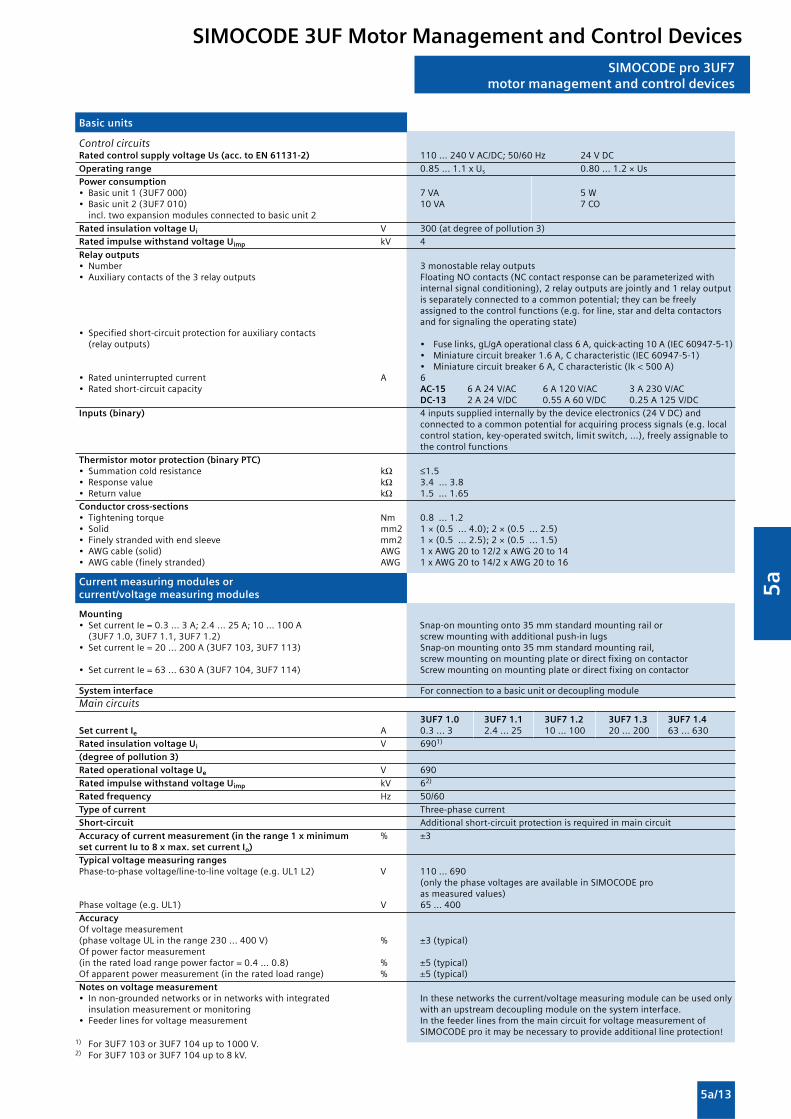
5a
5a/13
SIMOCODE pro 3UF7motor management and control devices
Basic units
Control circuitsRated control supply voltage Us (acc. to EN 61131-2) 110 ... 240 V AC/DC; 50/60 Hz 24 V DC
Operating range 0.85 ... 1.1 x Us 0.80 ... 1.2 × UsPower consumption• Basic unit 1 (3UF7 000) 7 VA 5 W• Basic unit 2 (3UF7 010) 10 VA 7 CO
incl. two expansion modules connected to basic unit 2
Rated insulation voltage Ui V 300 (at degree of pollution 3)Rated impulse withstand voltage Uimp kV 4
Relay outputs• Number 3 monostable relay outputs• Auxiliary contacts of the 3 relay outputs Floating NO contacts (NC contact response can be parameterized with
internal signal conditioning), 2 relay outputs are jointly and 1 relay outputis separately connected to a common potential; they can be freelyassigned to the control functions (e.g. for line, star and delta contactorsand for signaling the operating state)
• Specified short-circuit protection for auxiliary contacts(relay outputs) • Fuse links, gL/gA operational class 6 A, quick-acting 10 A (IEC 60947-5-1)
• Miniature circuit breaker 1.6 A, C characteristic (IEC 60947-5-1)• Miniature circuit breaker 6 A, C characteristic (Ik < 500 A)
• Rated uninterrupted current A 6• Rated short-circuit capacity AC-15 6 A 24 V/AC 6 A 120 V/AC 3 A 230 V/AC
DC-13 2 A 24 V/DC 0.55 A 60 V/DC 0.25 A 125 V/DCInputs (binary) 4 inputs supplied internally by the device electronics (24 V DC) and
connected to a common potential for acquiring process signals (e.g. localcontrol station, key-operated switch, limit switch, ...), freely assignable tothe control functions
Thermistor motor protection (binary PTC)• Summation cold resistance kΩ ≤1.5• Response value kΩ 3.4 ... 3.8• Return value kΩ 1.5 ... 1.65Conductor cross-sections• Tightening torque Nm 0.8 ... 1.2• Solid mm2 1 × (0.5 ... 4.0); 2 × (0.5 ... 2.5)• Finely stranded with end sleeve mm2 1 × (0.5 ... 2.5); 2 × (0.5 ... 1.5)• AWG cable (solid) AWG 1 x AWG 20 to 12/2 x AWG 20 to 14• AWG cable (finely stranded) AWG 1 x AWG 20 to 14/2 x AWG 20 to 16
Current measuring modules orcurrent/voltage measuring modules
Mounting• Set current Ie = 0.3 ... 3 A; 2.4 ... 25 A; 10 ... 100 A Snap-on mounting onto 35 mm standard mounting rail or
(3UF7 1.0, 3UF7 1.1, 3UF7 1.2) screw mounting with additional push-in lugs• Set current Ie = 20 ... 200 A (3UF7 103, 3UF7 113) Snap-on mounting onto 35 mm standard mounting rail,
screw mounting on mounting plate or direct fixing on contactor• Set current Ie = 63 ... 630 A (3UF7 104, 3UF7 114) Screw mounting on mounting plate or direct fixing on contactor
System interface For connection to a basic unit or decoupling moduleMain circuits
3UF7 1.0 3UF7 1.1 3UF7 1.2 3UF7 1.3 3UF7 1.4Set current Ie A 0.3 ... 3 2.4 ... 25 10 ... 100 20 ... 200 63 ... 630Rated insulation voltage Ui V 6901)
(degree of pollution 3)Rated operational voltage Ue V 690
Rated impulse withstand voltage Uimp kV 62)
Rated frequency Hz 50/60
Type of current Three-phase currentShort-circuit Additional short-circuit protection is required in main circuit
Accuracy of current measurement (in the range 1 x minimum % ±3set current Iu to 8 x max. set current Io)Typical voltage measuring rangesPhase-to-phase voltage/line-to-line voltage (e.g. UL1 L2) V 110 ... 690
(only the phase voltages are available in SIMOCODE proas measured values)
Phase voltage (e.g. UL1) V 65 ... 400
AccuracyOf voltage measurement(phase voltage UL in the range 230 ... 400 V) % ±3 (typical)Of power factor measurement(in the rated load range power factor = 0.4 ... 0.8) % ±5 (typical)Of apparent power measurement (in the rated load range) % ±5 (typical)Notes on voltage measurement• In non-grounded networks or in networks with integrated In these networks the current/voltage measuring module can be used only
insulation measurement or monitoring with an upstream decoupling module on the system interface.• Feeder lines for voltage measurement In the feeder lines from the main circuit for voltage measurement of
SIMOCODE pro it may be necessary to provide additional line protection!1) For 3UF7 103 or 3UF7 104 up to 1000 V.2) For 3UF7 103 or 3UF7 104 up to 8 kV.
SIMOCODE 3UF Motor Management and Control Devices

5a
5a/14
SIMOCODE pro 3UF7motor management and control devices
Current measuring modules or current/voltage measuring modules
Connection for main circuitFeed-through opening (diameter)Set current Ie = 0.3 ... 3 A; 2.4 ... 25 A mm 7.5Set current Ie = 10 ... 100 A mm 14.0Set current Ie = 20 ... 200 A mm 25.0Busbar connections1) 3UF7 100, 3UF7 101, 3UF7 102 3UF7 103, 3UF7 104Set current Ie A 20 ... 200 63 ... 630Terminal screw M8 x 25 M10 x 30Tightening torque Nm 10 ... 14 14 ... 24Solid with cable lug mm2 16 ... 952) 50 ... 2403)
Stranded with cable lug mm2 25 ... 1202) 70 ... 2403)AWG cable AWG 6 ... 3/0 kcmil 1/0 ... 500 kcmilConductor cross-sections for voltage measurementTightening torque Nm 0.8 ... 1.2Solid mm2 1 x (0.5 ... 4.0); 2 x (0.5 ... 2.5)Finely stranded with end sleeve mm2 1 x (0.5 ... 2.5); 2 x (0.5 ... 1.5)AWG cable (solid) AWG 1 x AWG 20 to 12/2 x AWG 20 to 14AWG cable (finely stranded) AWG 1 x AWG 20 to 14/2 x AWG 20 to 16
Decoupling modules
Mounting Snap-on mounting onto 35 mm standard mounting rail orscrew mounting with additional push-in lugs
DisplayGreen "READY" LED • Continuous light: "Ready"
System interfaces Left interface for connecting to a basic unit or to an expansion module,right interface only for connecting to a current/voltage measuring module.
Conductor cross-sectionsTightening torque Nm 0.8 ... 1.2Solid mm2 1 x (0.5 ... 4.0); 2 x (0.5 ... 2.5)Finely stranded with end sleeve mm2 1 x (0.5 ... 2.5); 2 x (0.5 ... 1.5)AWG cable (solid) AWG 1 x AWG 20 to 12/2 x AWG 20 to 14AWG cable (finely stranded) AWG 1 x AWG 20 to 14/2 x AWG 20 to 16
Digital modules
Mounting Snap-on mounting onto 35 mm standard mounting rail orscrew mounting with additional push-in lugs
Display• Green "READY" LED • Continuous light: "Ready"
• Flashing: "No connection to the basic unit"
System interfaces For connecting to a basic unit, another expansion module,a current measuring module or current/voltage measuring module or tothe operator panel
Control circuit
Rated insulation voltage Ui V 300 (at degree of pollution 3)
Rated impulse withstand voltage Uimp kV 4
Relay outputs• Number 2 monostable or bistable relay outputs (depending on the version)• Auxiliary contacts of the 2 relay outputs Floating NO contacts (NC contact response can be parameterized with
internal signal conditioning), all relay outputs are jointly connected to acommon potential, they can be freely assigned to the control functions(e.g. for line, wye and delta contactors and for signaling the operatingstate)
• Specified short-circuit protection for auxiliary contacts • Fuse links, gL/gG operational class 6 A, quick-acting 10 A (IEC 60947-5-1)(relay outputs) • Miniature circuit breaker 1.6 A, C characteristic (IEC 60947-5-1)
• Miniature circuit breaker 6 A, C characteristic (Ik<500 A)Rated uninterrupted current A 6Rated short-circuit capacity AC-15 6 A/24 V AC 6 A/120 V AC 3 A/230 V AC
DC-13 2 A/24 V DC 0.55 A/60 V DC 0.25 A/125 V DC
Inputs (binary) 4 externally supplied floating inputs, 24 V DC or 110 ... 240 V AC/DCdepending on the version; inputs jointly connected to common potentialfor sensing process signals (e.g.: local control station, key-operated switch,limit switch ...), freely assignable to the control functions
Conductor cross-sections• Tightening torque Nm 0.8 ... 1.2• Solid mm2 1 × (0.5 ... 4.0); 2 × (0.5 ... 2.5)• Finely stranded with end sleeve mm2 1 × (0.5 ... 2.5); 2 × (0.5 ... 1.5)• AWG cable (solid) AWG 1 x AWG 20 to 12/2 x AWG 20 to 14• AWG cable (finely stranded) AWG 1 x AWG 20 to 14/2 x AWG 20 to 16
1) Screw terminal is possible using a suitable 3RT19 ... box terminal.2) When connecting cable lugs according to DIN 46235, use the 3RT19 56-4EA1
terminal cover for conductor cross-sections from 95 mm2 to ensure phasespacing.
3) When connecting cable lugs according to DIN 46234 for conductor crosssections from 240 mm2 as well as DIN 46235 for conductor cross-sections from185 mm2, use the 3RT19 66-4EA1 terminal cover to ensure phase spacing.
SIMOCODE 3UF Motor Management and Control Devices

5a
5a/15
SIMOCODE pro 3UF7motor management and control devices
Possible
-- Not available
Earth leakage modules
Mounting Snap-on mounting onto 35 mm standard mounting rail orscrew mounting with additional push-in lugs
Display• Green "READY" LED • Continuous light: "Ready"
• Flashing: "No connection to the basic unit"
System interfaces For connecting to a basic unit, another expansion module, a currentmeasuring module or current/voltage measuring module or to theoperator panel
Control circuit
Connectable 3UL22 summation current transformerwith rated fault currents IN A 0.3/0.5/1• IGround fault ≤50 % IN No tripping• IGround fault ≥100 % IN Tripping
Response delay (conversion time) ms 300 ... 500, additionally delayable
Conductor cross-sections• Tightening torque Nm 0.8 ... 1.2• Solid mm2 1 × (0.5 ... 4.0); 2 × (0.5 ... 2.5)• Finely stranded with end sleeve mm2 1 × (0.5 ... 2.5); 2 × (0.5 ... 1.5)• AWG cable (solid) AWG 1 x AWG 20 to 12/2 x AWG 20 to 14• AWG cable (finely stranded) AWG 1 x AWG 20 to 14/2 x AWG 20 to 16
Temperature modules
Mounting Snap-on mounting onto 35 mm standard mounting rail or screwmounting with additional push-in lugs
Display• Green "READY" LED • Continuous light: "Ready"
• Flashing: "No connection to the basic unit"
System interfaces For connecting to a basic unit, another expansion module, a currentmeasuring module or current/voltage measuring module or to theoperator panel
Sensor circuits
Typical sensor circuits• PT100 mA 1 (typical)• PT1000/KTY83/KTY84/NTC mA 0.2 (typical)
Open-circuit/short-circuit detection• For sensor type PT100/PT1000 KTY83-110 KTY84 NTC• Open circuit --• Short-circuit• Measuring range °C -50 ... +500 -50 ... +175 -40 ... +300 +80 ... +160
Measuring accuracy at 20 °C ambient temperature (T20) K <±2
Deviation due to ambient temperature (in % of measuring range) % 0.05 per K deviation from T20
Conversion time ms 500
Connection type 2- or 3-conductor connection
Conductor cross-sections• Tightening torque Nm 0.8 ... 1.2• Solid mm2 1 × (0.5 ... 4.0); 2 × (0.5 ... 2.5)• Finely stranded with end sleeve mm2 1 × (0.5 ... 2.5); 2 × (0.5 ... 1.5)• AWG cable (solid) AWG 1 x AWG 20 to 12/2 x AWG 20 to 14• AWG cable (finely stranded) AWG 1 x AWG 20 to 14/2 x AWG 20 to 16
Analog modules
Mounting Snap-on mounting onto 35 mm standard mounting rail orscrew mounting with additional push-in lugs
Display• Green "READY" LED • Continuous light: "Ready"
• Flashing: "No connection to the basic unit"
System interfaces For connecting to a basic unit, another expansion module, a currentmeasuring module or current/voltage measuring module or to theoperator panel
SIMOCODE 3UF Motor Management and Control Devices

5a
5a/16
SIMOCODE pro 3UF7motor management and control devices
Analog modules
Control circuit
Inputs• Channels 2 (passive)• Parameterizable measuring ranges mA 0/4...20• Shielding Up to 30 m shield recommended, from 30 m shield required• Max. input current (destruction limit) mA 40• Accuracy % ±1• Input resistance W 50• Conversion time ms 150• Resolution bit 12• Open-circuit detection With measuring range 4 ... 20 mA
Output• Channels 1• Parameterizable output range mA 0/4...20• Shielding Up to 30 m shield recommended, from 30 m shield required• Max. voltage at output 30 V DC• Accuracy % ±1• Max. output load W 500• Conversion time ms 25• Resolution bit 12• Short-circuit resistant Yes
Connection type 2-conductor connection
Voltage isolation of inputs/output to the device electronics No
Conductor cross-sections• Tightening torque Nm 0.8...1.2• Solid mm2 1 x (0.5..4.0); 2 x (0.5..2.5)• Finely stranded with end sleeve mm2 1 x (0.5...2.5); 2 x (0.5...1.5)• AWG cable (solid) AWG 1 x AWG 20 to 12/2 x AWG 20 to 14• AWG cable (finely stranded) AWG 1 x AWG 20 to 14/2 x AWG 20 to 16
Operator panels
Mounting Mounted in a control cabinet door or in a front panel,IP54 with system interface cover
Display• Red/green/yellow LED "DEVICE" • Green: "Ready"
• Green flashing: "No connection to the basic unit"• Red: "Function test not OK; device is disabled"• Yellow: "Memory module or addressing plug detected"• Off: "No control supply voltage"
• Green "BUS" LED • Continuous light: "Communication with PLC/PCS"• Flashing: "Baud rate recognized/communicating with PC/PG"
• Red "GEN. FAULT" LED • Continuous light/flashing: "Feeder fault", e.g. overload trip• Green or yellow LEDs For assigning to any status signals, as required
Keys• Test/Reset • Resets the device after tripping
• Function test• Operation of a memory module or addressing plug
• Control keys for controlling the motor feeder, user-assignable
System interface• Front For plugging in a memory module, an addressing plug or
a PC cable for parameterization• Rear Connection to the basic unit or to an expansion module
Operator panels
Mounting Mounted in a control cabinet door or in a front panel,IP54 with system interface cover
Display• Red/green/yellow LED "DEVICE" • Green: "Ready"
• Green flashing: "No connection to the basic unit"• Red: "Function test not OK; device is disabled"• Yellow: "Memory module or addressing plug detected"• Off: "No control supply voltage"
• Green "BUS" LED • Continuous light: "Communication with PLC/PCS"• Flashing: "Baud rate recognized/communicating with PC/PG"
• Red "GEN. FAULT" LED • Continuous light/flashing: "Feeder fault", e.g. overload trip• 4 green LEDs For assigning to any status signals as required (preferably for the
feedback of switching states, e.g. On, Off, Left, Right, etc.)
Display Graphic display for indicating current measured values, operationaland diagnostics data or staus information
Keys• Control keys for controlling the motor feeder, user-assignable• Arrow keys Navigation in the display menu• Softkeys Various menu-dependent functions, e.g. test, reset, operation of a
memory module or addressing plug
System interface• Front For plugging in a memory module, an addressing plug or
a PC cable for parameterization• Rear Connection to the basic unit or to an expansion module
SIMOCODE 3UF Motor Management and Control Devices

5a
5a/17
SIMOCODE pro 3UF7motor management and control devices
Dimensional drawings
Basic unit 1, SIMOCODE pro C,3UF7 000
� �� � �
�� ���
��
�
��� �����
�
3UF7 100, 3UF7 101 current measuring module(straight-through transformer)
��� ������
� ��
�
��
� �� �
� � �
� �
3UF7 103 current measuring module (straight-through transformer)
� � �
� �
��
��
� � �
��
� �
��� �����
�
Basic unit 2, SIMOCODE pro V, 3UF7 010
�� ���
��
�
�� � �
� � �
��� �����
3UF7 102 current measuring module (straight-throughtransformer)
� � � �
�
��
�
�
��� �����
� �
� �
� �
SIMOCODE 3UF Motor Management and Control Devices

5a
5a/18
SIMOCODE pro 3UF7motor management and control devices
3UF7 103 current measuring module (busbar connection)
3UF7 104 current measuring module (busbar connection)
��� �����
� � �
� �
� � � ��
�� ��
���
� �
� �
�
�
� �
��
� �� �� �
�
��
���
��
� � �
�
� �
� � � �
����
���� ����
SIMOCODE 3UF Motor Management and Control Devices

5a
5a/19
3UF7 110, 3UF7 111 current/voltage measuring module(straight-through transformer)
��
� � ��� �
��
�
� �
��� ����
� �
� �
� �
3UF7 113 current/voltage measuring module (straight-throughtransformer)
� � �
� �
��
��
�� �
��
� �
��� ����
�
� �
� �
3UF7 112 current/voltage measuring module(straight-through transformer)
� �
�
� �� � �
� �
��
��
��� ����
� �
� �
� �
SIMOCODE pro 3UF7motor management and control devices
SIMOCODE 3UF Motor Management and Control Devices

5a
5a/20
SIMOCODE pro 3UF7motor management and control devices
3UF7 113 current measuring module (busbar connection)
��� ����
� � �
� �
� � � ��
�� ��
���
� �
� �
�
� �
3UF7 114 current/voltage measuring module (busbar connection)
6
14967
8832125
147
122
254811
9
NS
A0_
0040
4
145
SIMOCODE 3UF Motor Management and Control Devices

5a
5a/21
3UF7 200 operator panel
298 7
2936
NS
A0_
0038
5a
89
96
3UF7 210 operator panel with display
NS
A0_
0046
3a
5560
2933
89
96
3UF7 922 adapter for operator panel
NS
A0_
0046
4
6238
100
63 51
37
SIMOCODE pro 3UF7motor management and control devices
3UF7 920 door adapter
��� �����
� �
�
��
�
� �
3UF7 3 digital modules
3UF7 4 analog module
3UF7 5 ground-fault module
3UF7 7 temperature module
3UF7 15 decoupling module
� � ��
��
�� ��
� � � �
� � � � � � � �
SIMOCODE 3UF Motor Management and Control Devices

5a
5a/22
SIMOCODE pro 3UF7motor management and control devices
Schematics
Reversing starter with SIMOCODE pro
��
���
����
��
� � ��
� � �
� �
���
�� �� ��
���� ��
���
����
��
����
� �
� � �
� �
� � �
� ����
���
���
���
� � �
� � �
�����
�� �
���� ������
����� � ���
�
�� ��
� �
���
��
��������� � !������
�"#$%���
������� � !������ ������� � !������
���
��
�
�
�$�� �$��
� �
�"#$%����&� �������
�� ��
���%��%��%��%��
�� �� ������ ���� ����
�� �� ��
�� �� �� � �����
���
�'����
��
���'����
��
��
���� ����
�(�
&��%��
�(�
� )
��� ���
����
�
�� � �
���
�'��
���
�'��
��
� �� � � � � )
����
���� ���*��� � � � �
��� +��$����
����,�����-
� �
������-./�01/2-0213�041056.78������-./�01/2-0213�019/283041056.78������10-4�1::������10-4�041056.78� ����10-4�019/283041056.78
#;83-213�;-/84
&8<.08���+8/�:-942�87238782
�%�#�#&��;31����-7.0�9/.2
�9338/2�=82802.1/
�%�� �%�� ��� ����"����
Circuit diagrams for additional control functions can be referred to in the SIMOCODE pro system manual
More Information
System manual
For selection of equipment and for planning, it is recommendedthat the 3UF7 970-0AA0 . -0 system manual is consulted.
SIMOCODE 3UF Motor Management and Control Devices

5a
5a/23
General data
Function
�
��
������
��
��
��
A1/A2
15/1815/16
t
35 ms
NS
B00
859B1/A2
>
15/16
A1/A2
200 ms
t
15/18
NS
B00
860
>
tt
NS
B00
861
15/16
A1/A2
15/18
B1/A2
NS
B00
862
t t
15/16
A1/A2
15/18
NS
B00
863
15/16
A1/A2
15/18
Interval Pulse period
NS
B00
864
t
A1/A2
15/1815/16
t
NS
B00
865
35 ms>A1/A2
15/1815/16
B1/A2
t
NS
B00
867
>A1/A2
15/1815/16
B1/A2
35 ms
t
NS
B00
868
t1 t2t3
A1/A2
15/1815/16
B1/A2
123412341234
�
��
��
�������
Function Function chart 3RP 15 timing relayand 3RP 19 01 label set
Timing relay energized
Contact closed
Contact open
1 CO contact
With ON-delay A
OFF-delay B1)
with auxiliary voltage
OFF-delaywith auxiliary voltage
ON-delay and OFF-delay with auxiliary voltage C1)
(t = ton = toff)
Flashing, Dstarting with interval(pulse/interval 1:1)
Clock-pulse,starting with interval(dead time, pulse time, and time settingranges each separately adjustable)
Passing make contact E
Passing break contact F1)
with auxiliary voltage
Pulse-forming G1)
with auxiliary voltage(pulse generationat the output does not dependon duration of energizing)
Additive ON-delay H1)
with auxiliary voltage
1 CO contact
ON-delayThe two-wire timing relay is connected inseries with the load. Timing begins afterapplication of the exciting voltage.The semiconductor output then becomesconducting, and the load is under power.
1) Note on function with start contact: A new control signal at terminal B, after Function is possiblethe operating time has started, resets the operating time to zero. This doesnot apply to G, G and H, H , which are not retriggerable.
3RP, 3RT19 Timing Relays
3RP
15
05
-.A
3RP
19
01
-0A
Iden
tifi
cati
on
lett
er
3RP
15
1.
3RP
15
25
3RP
15
27
3RP
15
3.
3RP
15
40
3RP
15
55
3RP
15
7.

5a
5a/24
15/1815/16
t
A1/A2
25/2825/26
NS
B00
880
15/1815/16
t
25/2825/26
A1/A2
B1/A2
t
NS
B00
876
t
NS
B00
873
>A1/A2
15/1815/16
B1/A2
25/2825/26
35 ms
123412341234
Function Function chart 3RP 15 timing relayand 3RP 19 01 label set
Timing relay energized
Contact closed
Contact open
2 CO contact
With ON-delay A
ON-delay Aand instantaneous contact
OFF-delay B1)
with auxiliary voltage
OFF-delay B1)
with auxiliary voltageand instataneous contact
OFF-delay withoutauxiliary voltage
ON-delay and OFF-delay with auxiliary voltage C1)
(t = ton = toff)
ON-delay and OFF-delay with auxiliary voltage C 1)
and instantaneous contact (t = ton = toff)
Flashing, Dstarting with interval(pulse/interval 1:1)
Flashing Dstarting with interval(pulse/interval 1:1)and instantaneous contacts
Passing make contact E
Passing break contact Ewith instantaneous contact
Function is possible
General data
t
NS
B00
871
A1/A2
15/1815/16
25/2825/26
15/1815/16
t
A1/A2
NS
B00
872
21/2421/22
��
��
�
����
�
���
�������
��
�
15/16
A1/A2
200 ms
t
15/18
25/2825/26 N
SB
0087
5
>
15/1815/16
t21/2421/22
A1/A2
B1/A2
t
NS
B00
877
15/1815/16
t
A1/A2
25/2825/26
t
NS
B00
878
15/1815/16
21/2421/22
NS
B00
879A1/A2
t t
15/1815/16
21/2421/22
NS
B00
881A1/A2
t
3RP, 3RT19 Timing Relays
3RP
15
05
-.B
3RP
19
01
-0B
3RP
15
05
-.R
3RP
19
01
-0A
Iden
tifi
cati
on
lett
er
3RP
15
1.
3RP
15
25
3RP
15
27
3RP
15
3.
3RP
15
40
3RP
15
55
3RP
15
60
3RP
15
7.

5a
5a/25
General data
123412341234
Function Function chart 3RP 15 timing relayand 3RP 19 01 label set
Timing relay energized
Contact closed
Contact open
2 CO contact
Passing break contact F1)
with auxiliary voltage
Passing break contact F 1)
with auxiliary voltageand instantaneous contact
Pulse-forming G1)
with auxiliary voltage(pulse generation at theoutput does not depend onduration of energizing)
Pulse-forming G 1)
with auxiliary voltageand instataneous contact(pulse generation at theoutput does not depend onduration of energizing)
Additive ON-delay H1)
with auxiliary voltage
Additive ON-delay H 1)
with auxiliary voltage andinstantaneous contact
Wye-delta function YΔ
2 NO contact
Wye-delta function YΔ
3 NO contact
Wye-delta functionwith overtravel function2)
(idling)
1) Note on function with start contact: A new control signal at terminal B, after Function is possiblethe operating time has started, resets the operating time to zero. This doesnot apply to G, G and H, H , which are not retriggerable.
2) For function diagrams showing the various possibilities of operation of the3RP15 60-1S.30, see page 5/26.
15/1815/16
t
25/28
35ms
NS
B00
882
�
25/26
B1/A2
A1/A2
15/1815/16
t
35ms
21/2421/22
NS
B00
883A1/A2
B1/A2
>
15/1815/16
t
25/2825/26
A1/A2
B1/A2
35ms
NS
B00
884
�
15/1815/16
21/2421/22
A1/A2
B1/A2
t
NS
B00
885
35ms>
����
� � � �
��
��
���
�����
�
�
� ��
t
A1/A2
50ms
17/18
27/28
NS
B00
888
t 50 ms
NS
B00
889A1/A2
17/1817/28
��
����
��
��
���
�����
�
� �
���
������
�����
���
�
� � � � � � � �
� � � � �� � � � �
� � � � �
� � � � �
��� �� �
�
3RP, 3RT19 Timing Relays
3RP
15
05
-.B
3RP
19
01
-0B
3RP
15
05
-.R
3RP
19
01
-0A
Iden
tifi
cati
on
lett
er
3RP
15
1.
3RP
15
25
3RP
15
27
3RP
15
3.
3RP
15
40
3RP
15
55
3RP
15
60
3RP
15
7.

5a
5a/26
General data
3RP15 function table
3RP, 3RT19 Timing Relays
Possibilities of operation of the 3RP15 60-1S.30 timing relay
tY = Star time 1 ... 20 stIdling = Idling time (overtravel time) 30 ... 600 s
Operation 1:Start contact B./A2 is opened when supply voltage A./A2 is applied.The supply voltage is applied to A./A2 and there is no control signal onB./A2. This starts the YΔ timing. The idling time (overtravel time) isstarted by applying a control signal to B./A2. When the set time tIdling(30 ... 600 s) has elapsed, the output relays (17/16 and 17/28) arereset. If the control signal on B./A2 is switched off (minimum OFF period270 ms), a new timing is started.Comments:Observe response time (dead time) of 400 ms on energizing supplyvoltage until contacts 17/18 and 17/16 close.
Operation 2:Start contact B./A2 is closed when supply voltage A./A2 is applied.If the control signal B./A2 is already present when the supply voltageA./A2 is applied, no timing is started. The timing is only started whenthe control signal B./A2 is switched off.
Operation 3:Start contact B./A2 closes while star time is running.If the control signal B./A2 is applied again during the star time, theidling time starts and the timing is terminated normally.
Operation 4:Start contact B./A2 opens while delta time is running and is appliedagain.If the control signal on B./A2 is applied and switched off again duringthe delta time, although the idling time has not yet elapsed, the idlingtime (overtravel time) is reset to zero. If the control signal is re-appliedto B./A2, the idling time is restarted.
Application example based on standard operation(operation 1): For example, use of 3RP15 60 for compressor controlFrequent starting of compressors strains the network, the machine,and the increased costs for the operator. The new timing relay preventsfrequent starting at times when there is high demand for compressedair. A special control circuit prevents the compressor from beingswitched off immediately when the required air pressure in the tankhas been reached. Instead, the valve in the intake tube is closed andthe compressor runs in "Idling" mode for a specific time which can beset from 30 ... 600 s.If the pressure falls within this time, the motor does not have to berestarted again, but can return to nominal load operation from no-load operation.If the pressure does not fall within this idling time, the motor is switchedoff.The pressure switch controls the timing via B./A2.The supply voltage is applied to A./A2 and the start contact B./A2 isopen, i.e. there is no control signal on B./A2 when the supply voltageis applied. The pressure switch signals "too little pressure in system"and starts the timing by way of terminal B./A2. The compressor isstarted, enters YΔ operation, and fills the pressure tank.When the pressure switch signals "sufficient pressure", the controlsignal B./A2 is applied, the idling time (overtravel time) is started, andthe compressor enters no-load operation for the set period of timebetween 30 ... 600 s. The compressor is then switched off. Thecompressor is only restarted if the pressure switch responds again (lowpressure).
NS
B00
891
A./A2
B./A2
17/18 Y
17/28
17/16
Y Idlingtt 50 ms Yt 50 ms Idlingt300 ms
A./A2
B./A2
17/18 Y
17/28
17/16
Y
NSB00892
50 ms t Idlingt
A./A2
B./A2
17/18 Y
17/28
17/16
Y
NSB00893
50 mst Idling
t
NS
B00
894a
A./A2
B./A2
17/18 Y
17/28
17/16
Y Idlingt<t Idlingt< Idlingt50 ms
Operation 1
Operation 2
Operation 3
Operation 4
123412341234 Timing relay energized
Contact closed
Contact open
Note:The following applies to all operations: The pressure switch controls the timingvia B/A2.

5a
5a/27
3RP15 timing relays in industrial enclosure,22.5 mm
3RP, 3RT19 Timing Relays
Overview
StandardsThe timing relays comply with:
• EN 60721-3-3 "Environmental conditions"
• EN 61812-1/DIN VDE 0435 Part 2021
• "Electrical relays, timing relays"
• EN 61000-6-2 and EN 61000-6-4
• "Electromagnetic compatibility"
• EN 60947-5-1; (VDE 0660 Part 200)"Low-voltage controlgear, switchgear and systems –Electromechanical controlgear"
Functions
• Changes to the time setting ranges and the functions must becarried out in the de-energized state.
• Start input B1 or B3 must only be triggered when the supplyvoltage is applied.
• The same potential must be applied to A1 and B1 or A3 andB3. With two-voltage version, only one voltage range must beconnected.
• The activation of loads parallel to the start input is notpermissible when using AC control voltage (see diagrams).
• Surge suppression is integrated in the timing relay. Thisprevents the generation of voltage peaks on the supply voltagewhen the relay is switched on and off. No additional dampingmeasures are necessary.
• 3RP15 05-.R must not be operated next to heat sources >60 °C.
Accessories
Push-in lugs for screw mounting
Sealable covers
Lable set for making the multifunction relay
Parallel load on start input
K2A1
A2N
NSB0_00895a
L1
S1
K1B1
K2A1
A2N
NSB0_00896a
L1
S1 S1
K1B1
���������� ���������� �������� ���
���������� ������ �������������������� ����������������
����������
������� ������ ��
���� ������ � ������
!������������������������ ��
!������������������������

5a
5a/28
3RP15 timing relays in industrial enclosure,22.5 mm
Technical specifications
Type 3RP15 05 3RP15 11 3RP15 40 3RP15 60 3RP15 74 3RP15 273RP15 31 3RP15 12 3RP15 763RP15 32 3RP15 133RP15 33 3RP15 25
3RP15 55
Rated insulation voltage V AC 300; 500 for 3RP15 05-1BT10Degree of pollution 3Overvoltage category III
Operating range at excitation1) 0.85 ... 1.1 x Us at AC. 0.8 ... 1.25 x Us at DC;0.95 ... 1.05 times rated frequency
Rated power W 2 1Power consumption at 230 V AC, 50 Hz VA 6 22) 6 1
Rated operational current Ie• AC-140, DC-13 A -- 0.01 … 0.6• AC-15 at 24 ... 400 V, 50 Hz A 33) --• DC-13 at
- 24 V A 1 --- 125 V A 0.2 --- 250 V A 0.1 --
Uninterrupted thermal current Ith A 5 --
DIAZED protection4)
gL/gG operational class A 4 --
Switching frequency• When loaded with Ie 230 V AC 1/h 2500 5000• When loaded with 3RT10 16 contactor, 230 V AC 1/h 5000
Recovery time ms 150 300 150 50
Minimum ON period ms 355) -- 2006) --
Residual currentwith non-conducting output mA -- 5
Voltage dropwith conducting output VA -- 3.5
Short-time loading capacity A -- 10(up to10 ms)
Setting accuracywith reference to scale value Typical ±5 %
Repeat accuracy ≤ ±1 %
Mechanical endurance Operating cycles 30 x 106 100 x 106
Permissible ambient temperature During operation °C -25 … +60 During storage °C -40 … +85
Degree of protectionacc. to EN 60529 IP40 cover,
IP20 terminals
Connection type Screw terminals
• Terminal screw M 3 (standard screwdriver, size 2 and Pozidriv 2)• Solid mm2 1 x (0.5 ... 4) / 2 x (0.5 ... 2.5)• Finely stranded with end sleeve mm2 1 x (0.5 ... 2.5) / 2 x (0.5 ... 1.5)• AWG cables, solid or stranded AWG 2 x (20 ... 14)• Tightening torque Nm 0.8 … 1.2
Connection type Spring-loaded terminals
• Solid mm2 2 x (0.25 ... 1.5)• Finely stranded, with end sleeves acc. to DIN 46228 mm2 2 x (0.25 ... 1.5)• Finely stranded mm2 2 x (0.25 ... 1.5)• AWG cables, solid or stranded AWG 2 x (24 ... 16)
Permissible Any
Shock resistance g/ ms 15/11acc. to IEC 60068 for half-sine shock type
Vibration resistance 10 ... 55 Hz: 0.35 mmacc. to IEC 60068-2-6
Electromagnetic compatibility (EMC) EN 61000-6-2/EN 61000-6-4Tests acc. to basic specification
1) If nothing else is stated.2) Maximum inrush current 1A/100 ms.3) For 3RP15 05-.R: NC contact -> Ie = 1 A.4) Ik ≥1 kA weld-free according to IEC 60947-5-1.5) Minimum ON period with 3RP15 05-.BW30, 150 ms, until instantaneous contact has switched.6) For correct operation, observe minimum ON period.
3RP, 3RT19 Timing Relays

5a
5a/29
3RP15 timing relays in industrial enclosure,22.5 mm
Dimensional drawings
NSB0_01698a
A C74
86536
62 90
1522,5
62 110
15
1)
22,5
82
3RP15 05
3RP15 25-.B
3RP15 3
3RP15 40-.B
3RP15 60
3RP15 1
3RP15 25-.A
3RP15 27
3RP15 40-A
3RP15 55
3RP15 7
A C
83 102
84 103
1) For standard mounting rail according to EN 60715.
Screw-type terminal
Spring-loaded terminal
Removable terminal
Type
Schematics
3RP15 internal circuit diagrams (terminal designation to DIN 46199, Part 5)
3RP15 05-.A 3RP15 05-.A 3RP15 05-.A 3RP15 05-.A3RP15 1. 3RP15 3.-.A3RP15 25-.A
With ON-delay OFF-delay ON-delay and OFF-delay Flashingwith auxiliary voltage with auxiliary voltage
3RP15 05-.A 3RP15 05-.A 3RP15 05-.A 3RP15 05-.A
Passing make contact Passing break contact Pulse-forming Additive ON-delaywith auxiliary voltage with auxiliary voltage with auxiliary voltage
�� �
� � ��������
�
�
���� ��
���� ���� �� ���
��������
���� ��
���� ���� �� ���
� �
� ��
��� ��
��
������
���� ��
���� ���� �� ���
� �
� ��
��� �� �� �
� � ��������
�
�
���� ��
���� ���� �� ���
.
A3 15
A2 18 NS
B00
901
16
A1
AC/DC24V
AC100/127VAC200/240V
�������
���� ��
���� ���� �� ���
�
�
��� �� �
�� ��
������
���� ��
���� ���� �� ���
�
�
��� �� �
�� ��������
���� �
���� ��� �� ��
� �
� ��
��� ��
�
3RP, 3RT19 Timing Relays
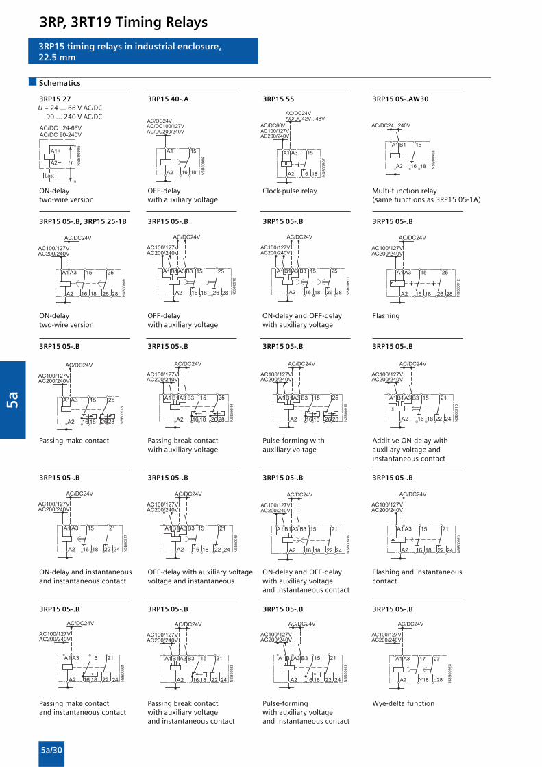
5a
5a/30
3RP15 timing relays in industrial enclosure,22.5 mm
Schematics
3RP15 27 3RP15 40-.A 3RP15 55 3RP15 05-.AW30
ON-delay OFF-delay Clock-pulse relay Multi-function relaytwo-wire version with auxiliary voltage (same functions as 3RP15 05-1A)
3RP15 05-.B, 3RP15 25-1B 3RP15 05-.B 3RP15 05-.B 3RP15 05-.B
ON-delay OFF-delay ON-delay and OFF-delay Flashingtwo-wire version with auxiliary voltage with auxiliary voltage
3RP15 05-.B 3RP15 05-.B 3RP15 05-.B 3RP15 05-.B
Passing make contact Passing break contact Pulse-forming with Additive ON-delay withwith auxiliary voltage auxiliary voltage auxiliary voltage and
instantaneous contact
3RP15 05-.B 3RP15 05-.B 3RP15 05-.B 3RP15 05-.B
ON-delay and instantaneous OFF-delay with auxiliary voltage ON-delay and OFF-delay Flashing and instantaneousand instantaneous contact voltage and instantaneous with auxiliary voltage contact
and instantaneous contact
3RP15 05-.B 3RP15 05-.B 3RP15 05-.B 3RP15 05-.B
Passing make contact Passing break contact Pulse-forming Wye-delta functionand instantaneous contact with auxiliary voltage with auxiliary voltage
and instantaneous contact and instantaneous contact
�2
� ��������
�
����*** �-������*��- ��
3���
�
� � ��������
�
�
������ ����� �� ��
���� �
�
� � ��������
�
�
���� ���� �� ���
.
�������
��
���� ������� �666���
� �
� ��
�
���� �666 ���
��������
�� �
� ��
�
���� ��
���� ���� �� ���
�
� ��������
� �������
���� ��
���� ���� �� ���
� �
� �
��� ��
�
�
� � ������
���� ��
���� ���� �� ���
� �
� �
��� ��
�
�
� �
�� �
� ��
�
���� ��
���� ���� �� ���
�
� ������
�
..
�� �
� � �������
�
�
���� ��
���� ���� �� ���
�
� � �������
���� ��
���� ���� �� ���
�
�
��� �� �
��
�
� � �������
���� ��
���� ���� �� ���
�
�
��� �� �
��
�
� � �������
���� ��
���� ���� �� ���
� �
� ��
��� ��
�
�
�� �
� ��
�
���� ��
���� ���� �� ���
� ��
�����
�������
���� ��
���� ���� �� ���
� �
� �
��� ��
�
�
�������
���� ��
���� ���� �� ���
� �
� �
��� ��
�
�
�� �
� ��
�
���� ��
���� ���� �� ���
� ������ �
.
�� �
� � ������
�
�
���� ��
���� ���� �� ���
� ������
���� ��
���� ���� �� ���
�
�
��� �� �
��
� ��
���� �
���� ��
���� ���� �� ���
�
�
��� �� �
��
�
��
>�� ������ �
��
���� ��
���� ���� �� ���
�
�
U = 24 ... 66 V AC/DC90 ... 240 V AC/DC
3RP, 3RT19 Timing Relays

5a
5a/31
3RP15 timing relays in industrial enclosure,22.5 mm
3RP15 05-.BW30/-1BT20/-.RW30 3RP15 25-. BR30 3RP15 25-. BW30 3RP15 40-.B
Multi-fuction relay With ON-delay With ON-delay OFF-delay without(for funcions see function table) auxiliary voltage
3RP15 60-.S 3RP15 7.-.M20 3RP15 76
Wye-delta timing relay with Wye-delta timing relay Wye-delta timing relayovertravel function (idling)
���������
� � � � � � � �
� �
� �
� �
� �
� �
� � � � � � � � � � � �
� � � �
� � � � � � � � �
� � � � � � �
�� ��
�� ����
��
���� ���
�����
��
�� ��
��
��
��
��
� � � �
� � � � ����� �
�
� �
� ��
� � � � � � � � � � �� � � � � � � � � �
� � � � � � � �
� �
� �
� �
� � �� � ���� ��
� �� �
� � � � � � �
� � � � � � � �
� � �
��
����� ����� ��
��
��������
��������������������
����������
��
�� ��� �� �!
��������������������
��� �� �
��������
�
���!
�������"""����
�
�� ��������
�!
��
��
Position of the connection terminals
3RP15 05-.A 3RP15 05-.AA40 3RP15 05-.AW 3RP15 05-.BP/-.BQ 3RP15 05-.BW 3RP15 05-1BT
3RP15 05-.RW 3RP15 1. 3RP15 25-1A. or -1B. 1) 3RP15 27 3RP15 3 .
3RP15 40 3RP15 55 3RP15 60 3RP15 7.
Note : All the diagrams show the view onto the connection terminals.1) Depending on the version
A1 B1 15
A3 B3
16 18 A2NSB00996
for 1changeovercontact
A1 B1 15
16 18 A2NSB0_01605
A1
for 2changeover contacts
�� � �
�! �� ��������
�� ��
�� ��
�! �� ���������
� ���
���� ���
����!
�����
�� ��
�! �� ���������
� ���
���� ���
����!
�����
�� ��
�! �� ���������
� ���
���� ���
����!
�����
�� �� �
�! �� ���������
�
�! ��
�� �� �
�! �� ���������
�� �
�! �� ��
�
�! ��
�� �� �
�! �� ���������
�� ��
���������
A1 B1 15
A3 B3
16 18 A2NSB00996
for 1changeovercontact
�� �� �
�! �� ���������
A1 15
16 18 A2
25
26 28
A1 15
16 18 A2NSB0_01004a
A1
A2
for 1changeovercontact
for 2changeovercontacts
�� ��
�� �� ��
�!
��
������
�� �� �� �� ��
�� �� �������!
3RP, 3RT19 Timing Relays

5a
5a/32
#�
������!
�$%&&'
%�$%('
)�
�
��& �*+&$��&&"""�'
�� �� ��
�� �� �!)� )�
)� )��� ��
�� ��
)� )� )��� �� ��
�� �� ��
�� ��
��
��
�� ��,�
3RP15 circuit diagrams
Control circuits (example circuits)
with 3RP15 74 and 3RP15 76 wye-delta timing relays Control circuit (example circuit)with 3RP15 60 wye-delta timing relays
For momentary-contact operation For maintained-contact operation Legend:Size S00 to S3 Size S00 to S3 S0 Button "OFF"
S1 Button "ON"S Maintained-contact buttonK1 Line contactorK2 Star contactorK3 Delta contactorK4 Timer or timing relayF0 FuseF1 Overload relayP1 Pressure switch
Note:
The contact element 17/18 is only closed in the wye stage;the contact element is open in the delta stage as well as in thede-energized state.
#�
)�)�
����� ��
��
�
�$%&&'
%�$%('
��
��
��
)�
)�
)�
�
�
#��!
��& �*�&$��'&&"""�
��
��)�
�� ��
)�
��
)�
��
��
)� )���
��� �
� �
� �� �
� � � � � � � �
� �
� � � � � �
� � � � �
�
� �
� �
� �
� � �
� � � � � � � � � � � � � � � � � �
�
� �� �
� � �
� �
�
�
� �
� �
� � � �
�
�
� �
� �
�
�
�
3RP15 timing relays in industrial enclosure,22.5 mm
3RP, 3RT19 Timing Relays

5a
5a/33
Overview
Solid-state line monitoring relays provide maximum protectionfor mobile machines and plants or for unstable networks. Networkand voltage faults can be detected early and rectified before fargreater damage ensues.
Depending on the version, the relays monitor phase sequence,phase failure with and without N conductor monitoring, phaseunbalance, undervoltage or overvoltage.
Phase unbalance is evaluated as the difference between thegreatest and the smallest phase voltage relative to the greatestphase voltage. Undervoltage or overvoltage exists when at leastone phase voltage deviates by 20 % from the set rated systemvoltage or the directly set limit values are overshot or undershot.The rms value of the voltage is measured.
With the 3UG46 17 or 3UG46 18 relay, a wrong direction ofrotation can also be corrected automatically.
Line Monitoring
3UG45 11 monitoring relays
The 3UG45 11 phase sequenced relay monitors the phasesequence in a three-phase network. No adjustments are requiredfor operation. The device has an internal power supply and workusing the closed-circuit principle. If the phase sequence at theterminals L1-L2-L3 is correct, the output relay picks up after thedelay time has elapsed and the LED is lit. If the hase sequence iswrong, the output relay remains in its rest position.
Note: When one phase fails, connected loads (motor windings,lamps, transformers, coils, etc.) create a feedback voltage at theterminal of the failed phase due to the network coupling. Becausethe 3UG45 11 relays are not resistant to voltage feedback, sucha phase failure is not detected. Should this be required, then the3UG45 12 monitoring relay must be used.
Function
3UG45 12 monitoring relays
The 3UG45 12 line monitoring relay monitors three-phasenetworks with regard to phase sequence, phase failure and phaseunbalance of 10 %. Thanks to a special measuring method, aphase failure is reliably detected in spite of the wide voltage rangefrom 160 ... 690 V AC and feedback through the load of up to 90%. The device has an internal power supply and works using theclosed-circuit principle. No adjustments are required. When themains voltage is switched on, the green LED is lit. If the phasesequence at the terminals L1-L2-L3 is correct, the output relaypicks up. If the phase sequence is wrong, the red LED flashes andthe output relay remains in its rest position. If a phase fails, thered LED is permanently lit and the output relay drops.
Note: The red LED is a fault diagnostic indicator and does notshow the current relay status. The 3UG45 12 monitoring relay issuitable for line frequencies of 50/60 Hz.
Correct phase sequence
Wrong phase sequence
Phase failure
Wrong phase sequence
NS
B0_
0156
5
11/14
L1-L2-L3
11/12
21/24
21/22
ON
NS
B0_
0156
7
11/14
L1-L2-L3L2-L3L1-L2-L3
11/12
21/24
21/22
LED rd
OFF OFFONPhase loss
NS
B0_
0156
6
11/14
L3-L2-L1
11/12
21/24
21/22
OFF
NS
B0_
0156
8
11/14
11/12
L3-L2-L1
21/24
21/22
LED rd
FLASHPhase sequence
OFFOFF
3UG Monitoring Relays for Electrical and Additional Measurements

5a
5a/34
NSB0_01569
11/14
-20%L1-L2-L3L2-L3L1-L2-L3
n3~U5%
11/12
21/24
21/22
LED rd
DelayOFFOFF OFF
Hysteresis
ONPhase loss
ON
NS
B0_
0157
0
11/14
L3-L2-L1
11/12
21/24
21/22
LED rd
FLASHPhase sequence
OFFOFF
Overview
Line Monitoring
3UG45 11 monitoring relays
The 3UG45 13 line monitoring relay monitors three-phasenetworks with regard to phase sequence, phase failure, phaseunbalance and undervoltage of 20 %. The device has an internalpower supply and works using the closed-circuit principle. Thehysteresis is 5 %. The integrated response delay time is adjustablefrom 0 ... 20 s and responds to undervoltage. If the direction isincorrect, the device switches off immediately. Thanks to a specialmeasuring method, a phase failure is reliably detected in spite ofthe wide voltage range from 160 ... 690 V AC and feedback up to80 % through the load. When the mains voltage is switched on,the green LED is lit. If the phase sequence at the terminals L1-L2-L3 is correct, the output relay picks up. If the phase sequence iswrong, the red LED flashes and the output relay remains in itsrest position. If a phase fails, the red LED is permanently lit andthe output relay drops.
Note: The red LED is a fault diagnostic indicator and does notshow the current relay status. The 3UG45 13 monitoring relay issuitable for line frequencies of 50/60 Hz.
Phase failure and undervoltage
Wrong phase sequence
3UG46 15/3UG46 16 monitoring relays
The 3UG46 15/3UG46 16 line monitoring relay has a wide voltagerange and an internal power supply. The device is equipped witha display and is parameterized using three buttons. The 3UG4615 device monitors three-phase networks with regard to phasefailure, undervoltage, overvoltage and phase sequence. The3UG46 16 monitoring relay monitors the neutral conductor aswell. The hysteresis is adjustable from 1 ... 20 V. In addition thedevice has two separately adjustable delay times for overvoltageand undervoltage from 0 ... 20 s in each case. If the direction isincorrect, the device switches off immediately. Thanks to a specialmeasuring method, a phase failure is reliably detected in spite ofthe wide voltage range from 160 ... 690 V AC and feedbackthrough the load of up to 80 %.
The 3UG46 15/ 3UG46 16 monitoring relay can be operated onthe basis of either the open-circuit or closed-circuit principle andwith manual or auto RESET.
With the closed-circuit principle selected
NS
B0_
0157
1
11/14
L3-L2-L1
11/12
21/24
21/22
NS
B0_
0157
2
11/14
11/12
21/24
21/22
L1-L2-L3L1-L2-L3-N
L2-L3L1-L2-L3
L1-L2-L3L1-L2-L3-N
NS
B0_
0157
3
<
21/24
21/22
11/14
11/12
x-yHysteresis
Delay
NS
B0_
0157
4
>x-y
21/24
21/22
11/14
11/12
Hysteresis
Delay
Wrong phase sequence
Phase failure
Undervoltage
Overvoltage
3UG Monitoring Relays for Electrical and Additional Measurements

5a
5a/35
Line Monitoring
Technical specifications
1) Absolute limit values.1) Note: This is a Class A product. In the household environment this device
may cause radio interference. In this case the user must introduce suitablemeasures.
3UG45 3UG45 3UG45 3UG45 12 3UG45 13 3UG46 14 3UG46 15 3UG46 1611-..N20 11-..P20 11-..Q20
General data
Rated control supply voltage Us1) V 160 … 260 320 … 500 420 … 690 160 … 690 90 … 400
Rated frequency Hz 50/60
Rated power, typical• At 230 V AC W/VA 2/4 -- -- 2/2.5• At 400 V AC W/VA -- 2/8 -- 2/3.5• At 460 V AC W/VA -- -- 2/8 2/4
Installation width mm 22.5
RESET Auto-RESET automatic/manual
Principle of operation Closed-circuit Closed-circuit, open-circuit(3UG46 17/3UG46 18:closed-circuit)
Availability time after application of Us ms 200 1.000
Response time once a switching threshold is ms max. 450reached
Unbalance % -- 10 20 0; 5 ... 20 3UG46 15/3UG46 16:Through thresholdvalues3UG46 17/3UG46 18:0; 5 ... 20
Adjustable tripping delay time s -- 0.1 ... 20
Adjustable ON-delay time s -- 0.1 … 20 --
Mains buffering time, minimum ms 10 30
Rated insulation voltage Ui V 690Degree of pollution 3Overvoltage category III acc. to VDE 0110
Rated impulse withstand voltage kV 6
Permissible ambient temperature
• During operation °C -25 … +60• During storage °C -40 … +85
EMC tests2) IEC 60947-1/ IEC 61000-6-2 / IEC 61000-6-4
Degree of protection• Enclosure IP40• Terminals IP20
Vibration resistance acc. to IEC 60068-2-6 1 ... 6 Hz: 15 mm; 6 ... 500 Hz: 2 g
Shock resistance acc. to IEC 60068-2-27 12 shocks (half-sine 15 g/11 ms)
Connection type Screw terminals
• Terminal screw M 3 (standard screwdriver, size 2 and Pozidriv 2)• Solid mm2 1 x (0.5 ... 4) / 2 x (0.5 ... 2.5)• Finely stranded with end sleeve mm2 1 x (0.5 ... 2.5) / 2 x (0.5 ... 1.5)• AWG cables, solid or stranded AWG 2 x (20 ... 14)• Tightening torque Nm 0.8 … 1.2
Measuring circuit
Measuring range AC 50/60 Hz rms value V 160 ... 260 320 ... 500 420 ... 690 160 ... 690
Setting range V 200...690 160...690 90...400
Measuring accuracy % -- ±5
Repeat accuracy at constant parameters % -- ±1
Setting accuracy -- ±10 % ±1Vreferred toset value
Accuracy of digital display -- ±1 digit
Deviations for temperature fluctuations %/°C -- ±0.1
Hysteresis for voltage V -- 5 % of 1 ... 20 Vset value
Hysteresis for unbalance % -- (set 3UG46 17/3UG46 18:value - 2) (set value - 2)
Deviation for frequency fluctuation % -- ±1
3UG Monitoring Relays for Electrical and Additional Measurements

5a
5a/36
Line Monitoring
Technical specifications
3UG45 3UG45 3UG45 3UG45 12 3UG45 13 3UG46 14 3UG46 15 3UG46 1611-..N20 11-..P20 11-..Q20
General data
Load capacity of the output relay• Thermal current Ith A 5
Rated operational current Ie at• AC-15/24 ... 400 V A 3• DC-13/24 V A 1• DC-13/125 V A 0.2• DC-13/250 V A 0.1
Minimum contact load at 17 V DC mA 5
Output relay with DIAZED fusegL/gG operational class A 4
Electrical endurance AC-15 Million 0.1operatingcycles
Mechanical endurance Million 10operatingcycles
Dimensional drawings
NSB0_01606b
A B C74
86536
62 90
1522,5
62 110
1522,5
82
1)
Type 3UG45 11-.A 3UG45 11-.B 3UG46 163UG45 12-.A 3UG45 12-.B 3UG46 18
3UG45 133UG46 143UG46 153UG46 17
A B C
Removable terminal
Screw-type terminal 83 92 102
1) For standard mounting rail according to EN 60715.
3UG Monitoring Relays for Electrical and Additional Measurements

5a
5a/37
Line Monitoring
Schematics
3UG45 11-.A 3UG45 11-.B 3UG46 163UG45 12-.A 3UG45 12-.B 3UG46 18
3UG45 133UG46 143UG46 153UG46 17
� � � � � � � �
�
�
�
� � � �
� �� �
�
� ! �
� � � � � � � �
�
�
�
� � � �
� �� �
�
� �
�
� �
� ! �
� � � � � � � �
�
�
�
� � � �
� �� �
�
� �
�
� �
�
�
� ! �
Note: It is not necessary to protect the measuring circuit for deviceprotection. The protective device for line protection depends on thecross-section used.
Position of the connection terminals
3UG45 11-.A 3UG45 11-.B 3UG46 163UG45 12-.A 3UG45 12-.B 3UG46 18
3UG45 133UG46 143UG46 153UG46 17
���� ���
�
� �
� � � �
���� ���
�
� �
� � � �
� � � � �
���� � �
�
� �
� � � �
� � � � �
�
3UG Monitoring Relays for Electrical and Additional Measurements

5a
5a/38
Power factor and active current monitoring
Overview
The 3UG46 41 power factor and active current monitoring deviceenables the load monitoring of motors.
Whereas power factor monitoring is used above all for monitoringno-load operation, the active current monitoring option can beused to observe and evaluate the load factor over the entire torquerange.
3UG46 41 monitoring relays
The 3UG46 41 monitoring relay is self-powered and serves thesingle-phase monitoring of the power factor or performsovershoot, undershoot or window monitoring of the activecurrent depending on how it is parameterized.
The load to be monitored is connected in front of the IN terminal.The load current flows over the IN and Ly/N terminals. The settingrange for the power factor is 0.1 ... 0.99 and for the active currentIres 0.2 ... 10 A.
If the supply voltage is switched on and no load current is flowing,the display indicates Ι < 0.2 and a symbol for overshoot,undershoot or window monitoring.
If the motor is now switched on and the current exceeds 0.2 A,the set ON-delay time begins. During this time, an undershootingor overshooting of the set limit values will not lead to a relayresponse of the changeover contact.
If the operational flowing active current and/or the power factorvalue falls below or exceeds the respective set threshold value,the spike delay begins. When this time has expired, the relaychanges its switch position. The relevant measured variables forovershooting and undershooting in the display flashes. If themonitoring of active current overshooting is deactivated(Ιres = OFF) and the load current drops below the lowermeasurement range threshold (0.2 A), then the CO contactsremain unchanged. If a threshold value is set for the monitoringof active current undershooting, then undershooting of themeasurement range threshold (0.2 A) will result in a response ofthe CO contacts.
The relay operates either according to the open-circuit or closed-circuit principle.
If the device is set to Auto-RESET (Memory = No), depending onthe set principle of operation, the switching relay returns to its
initial state and the flashing ends when the hysteresis thresholdis reached.
If manual reset is selected in the menu (Memory = Yes), theswitching relay remains in its current switching state and thecurrent measured value and the symbol for undershooting andovershooting continues to flash, even when the measuredvariable reaches a permissible value again. This stored fault statuscan be reset by pressing the UP and DOWN key simultaneouslyfor 2 seconds, or by switching the supply voltage off and back onagain.
Function
With the closed-circuit principle selected
Behavior upon undershooting of the measurement range limitwith activated monitoring of Ιres
Behavior upon undershooting of the measurement range limitwith deactivated monitoring of active current undershooting
NS
B0_
0165
8a21/22
21/24
11/12
11/14
Lx-Ly/N
I = 0,2 A
I = 0
I < 0,2 A
Ires
onDelayonDelayN
SB
0_01
917
21/22
21/24
11/12
11/14
Lx-Ly/N
I = 0,2 A
I = 0
I < 0,2 A
Ires = off
onDelayonDelay
3UG Monitoring Relays for Electrical and Additional Measurements

5a
5a/39
Power factor and active current monitoring
Overshooting of active current
Undershooting of active current
Window monitoring of active current
NS
B0_
0165
9
21/24
21/22
11/14
11/12
> res
= 0
res
DelayonDelay
Hysteresis
NS
B0_
0166
0
21/24
21/22
11/14
11/12
< res
= 0
res
DelayonDelay
Hysteresis
NS
B0_
0166
1
21/24
21/22
11/14
11/12
< res
= 0
> res
res
res
DelayonDelay Delay
Hysteresis
Hysteresis
Overshooting of power factor
Undershooting of Power factor
Window monitoring of power factor
NS
B0_
0166
2
21/24
21/22
11/14
11/12
> cos
cos = 0
cos
p.f.
DelayonDelay
Hysteresis 0,10
cos = 0
NS
B0_
0166
3
21/24
21/22
11/14
11/12
< cos
cosp.f.
Hysteresis 0,10
DelayonDelay
cos = 0
NS
B0_
0166
4
21/24
21/22
11/14
11/12
> cos < cos
cos
cosp.f.
Hysteresis0,10
DelayonDelay Delay
Legend
cos ϕ: p.f.
3UG Monitoring Relays for Electrical and Additional Measurements

5a
5a/40
Power factor and active current monitoring
Technical specifications
Type 3UG46 41
General data
Rated control supply voltage Us V 90 … 690
Rated frequency Hz 50/60
Rated power, typical• At 200 V AC VA 2.0• At 400 V AC VA 2.7• At 460 V AC VA 3.1
Width mm 22.5
RESET Automatic/ manual
Principle of operation Closed-circuit principle, open-circuit principle
Availability time after application of Us ms 1000
Response time once a switching threshold is reached ms Max. 450
Adjustable tripping delay time s 0.1 ... 20
Adjustable ON-delay time s 0 ... 99
Mains buffering time, minimum ms 10
Rated insulation voltage UiDegree of pollution 3Overvoltage category III acc. to VDE 0110 V 690
Rated impulse withstand voltage kV 6
Permissible ambient temperature• During operation °C -25 … +60• During storage °C -40 … +85
EMC tests1) IEC 60947-1/ IEC 61000-6-2 / IEC 61000-6-4
Degree of protection• Enclosure IP40• Terminals IP20
Vibration resistance acc. to IEC 60068-2-6 1 ... 6 Hz: 15 mm; 6 ... 500 Hz: 2 g
Shock resistance acc. to IEC 60068-2-27 12 shocks (half-sine 15 g/11 ms)
Connection type Screw terminals• Terminal screw M 3 (standard screwdriver, size 2 and Pozidriv 2)• Solid mm2 1 x (0.5 ... 4) / 2 x (0.5 ... 2.5)• Finely stranded with end sleeve mm2 1 x (0.5 ... 2.5) / 2 x (0.5 ... 1.5)• AWG cables, solid or stranded AWG 2 x (20 ... 14)• Tightening torque Nm 0.8 … 1.2
Measuring circuit
Measurable active current ΙΙΙΙΙres A 0.2 ... 10
Max. permissible load current A 10
Peak current < 1 s A 50
Adjustable response value
Phase displacement angle 0.1 ... 0.99
DIAZED protection, gL/gG operational class A 16
Measuring accuracy % 10
Repeat accuracy at constant parameters % 1
Accuracy of digital display ± 1 digit
Deviations for temperature fluctuations %/°C ±0.1
Hysteresis Phase angle 0.10
Hysteresis Active current monitoring A 0.1 ... 2.0
Note: This is a Class A product. In the household environment this devicemay cause radio interference. In this case the user must introduce suitablemeasures.
3UG Monitoring Relays for Electrical and Additional Measurements

5a
5a/41
Power factor and active current monitoring
Technical specifications
Type 3UG46 41
Control circuits
Number of CO contacts for auxillary contacts
Load capacity of the output relay• Thermal current Ιth
Rated operational current Ie at• AC-15/24 ... 400 V A 3• DC-13/24 V A 1• DC-13/125 V A 0.2• DC-13/250 V A 0.1
Minimum contact load at 17 V DC mA 5
Output relay with DIAZED fusegL/gG operational class A 4
Electrical endurance AC-15 Million 0.1operatingcycles
Mechanical endurance Million 10operatingcycles
Dimensional drawings
Type 3UG46 41A B
Removable terminal
Screw-type terminal 83 92
1) For standard mounting rail according to EN 60715.
NSB0_01699b
A B74
865
62 110
1522,5
72
1)
3UG Monitoring Relays for Electrical and Additional Measurements

5a
5a/42
Power factor and active current monitoring
Schematics
1-phase motors 3-phase motors 3-phase motorswith transformers for currents > 10 A
Position of the connection terminals
3UG46 41
M1~
Lx IN
12
14
22
24
N/L
L/N
21
Ly/N
113UG46 41
cos / r
cos / r
NSB0_01654b
Lx IN
12
14
22
24
LnLnLnn = 1,2,3
21
M3~
11
Ly/N
3UG46 41
cos / r
cos / r
NSB0_01655b
Lx IN
12
14
22
2421
M3~
Ly/N
11
3UG46 41
NSB0_01656b
cos / r
cos / r
LnLnLnn = 1,2,3
NS
B0_
0165
7
Lx
12 14
IN
22 21 24
11
Ly/N
3UG Monitoring Relays for Electrical and Additional Measurements

5a
5a/43
Residual current monitoring:Residual-current monitoring relays
Overview
The 3UG46 24 residual-current monitoring relay is used togetherwith the 3UL22 summation current transformer for plantmonitoring.
3UG46 24 monitoring relays
The main conductor and any neutral conductor to which a load isconnected, are routed through the opening of the annular stripwound core of a summation current transformer. A secondarywinding is placed around this annular strip-wound core to whichthe monitoring relay is connected.
If operation of a plant is fault-free, the sum of the inflowing andoutward currents equals zero. In this case, no voltage is inducedin the secondary winding of the summation current transformer.
However, if an insulation fault occurs downstream of the residualcurrent operated circuit breaker, the sum of the inflowing currentsis greater than that of the outward currents.
The differential current - the residual current - induces a secondarycurrent in the secondary winding of the transformer. This currentis evaluated in the monitoring relay and is used on the one handto display the actual residual current and on the other, to switchthe relay if the set warning or tripping threshold is overshot.
Function
If the measured residual current exceeds the set warning value,the associated changeover contact instantly changes theswitching state and an indication appears on the display. If themeasured residual current exceeds the set tripping value, the setdelay time begins and the associated relay symbol flashes. Onexpiry of this time, the associated changeover contact changesthe switching state.
ON-delay time for motor start
To be able to start an operating mechanism, once the auxiliaryvoltage has been applied for an adjustable ON-delay time, anddepending on whether the open-circuit or closed-circuit principleis selected, the output relay switches to the GO state.
The changeover contacts do not react if the set threshold value isovershot during this period.
3UG Monitoring Relays for Electrical and Additional Measurements

5a
5a/44
With the closed-circuit principle selected
Residual current monitoring with Auto-RESET (Memory = no)
If the device is set to Auto-RESET (Memory = No), the relayswitches for the tripping value once the value falls below the sethysteresis threshold and the display stops flashing. The associatedrelay changes its switching state if the value falls below the fixedhysteresis value of 5 % of the warning value. Any overshoots aretherefore not stored.
Note:
The neutral conductor must not be grounded downstream of thesummation current transformer as this may impair the functionof the residual current monitoring device.
Residual current monitoring:Residual-current monitoring relays
Hysteresis
Mem = no
Hysteresis = 5 %
onDelay Delay
NS
B0_
0181
2
11/14
Lx-Ly/N
11/12
21/24
21/22
>
= 0
!
! >
Residual current monitoring with Manual-RESET (Memory = yes)
If Manual-RESET is selected in the menu, the output relay remainsin its current switching state and the current measured value andthe symbol for overshooting continues to flash, even when themeasured residual current returns to a permissible value. Thisstored fault status can be reset by pressing the UP and DOWNkey simultaneously for > 2 seconds, or by switching the supplyvoltage off and back on again.
Reset
Hysteresis
Mem = yes
Hysteresis = 5 %
onDelay Delay
NS
B0_
0181
3
11/14
Lx-Ly/N
11/12
21/24
21/22
>
= 0
!
! >
3UG Monitoring Relays for Electrical and Additional Measurements

5a
5a/45
Residual current monitoring:Residual-current monitoring relays
Technical specifications
Type 3UG46 24
General data
Rated control supply voltage Us V 90 … 6901)
Rated frequency Hz 50/60
Rated power, typical• At 90 V AC VA 2.8• At 200 V AC VA 2.4• At 400 V AC VA 3.1• At 460 V AC VA 3.2• At 690 V AC VA 4.7
Width mm 22.5
RESET Automatic/ manual
Principle of operation Closed-circuit principle, open-circuit principle
Availability time after application of Us ms 1000
Response time once a switching threshold is reached ms Max. 300
Adjustable delay time s 0.1 ... 20
Mains buffering time, minimum ms 10
Rated insulation voltage UiDegree of pollution 3Overvoltage category III acc. to VDE 0110 V 690
Rated impulse withstand voltage kV 6
Permissible ambient temperature• During operation °C -25 … +60• During storage °C -40 … +85
EMC tests2) IEC 60947-1/ IEC 61000-6-2 / IEC 61000-6-4
Degree of protection• Enclosure IP40• Terminals IP20
Vibration resistance acc. to IEC 60068-2-6 1 ... 6 Hz: 15 mm; 6 ... 500 Hz: 2 g
Shock resistance acc. to IEC 60068-2-27 12 shocks (half-sine 15 g/11 ms)
Connection type Screw terminals• Terminal screw M 3 (standard screwdriver, size 2 and Pozidriv 2)• Solid mm2 1 x (0.5 ... 4) / 2 x (0.5 ... 2.5)• Finely stranded with end sleeve mm2 1 x (0.5 ... 2.5) / 2 x (0.5 ... 1.5)• AWG cables, solid or stranded AWG 2 x (20 ... 14)• Tightening torque Nm 0.8 … 1.2
Connection type Spring-loaded terminals
• Solid mm2 2 x (0.25 ... 1.5)• Finely stranded with end sleeve mm2 2 x (0.25 ... 1.5)• Finely standed mm2 2 x (0.25 ... 1.5)• AWG cables, solid or stranded AWG 2 x (24 ... 16)
Measuring circuit
Measurable active current ΙΙΙΙΙres A 10 ... 120 % ΙΔn (ΙΔn : rated residual current of the transformer)
Adjustable response value
Residual current 10 ... 100 % ΙΔn
Warning 10 ... 100 % ΙΔn
Measuring accuracy % ±5
Repeat accuracy at constant parameters % ±1
Accuracy of digital display ± 1 digit
Deviations for temperature changes %/°C ±0.1
Hysteresis for residual current LSB3) up to 50 % ΙΔn
Hysteresis for warning threshold A 5 % ΙΔn
1) Absolute limit values.2) Note: This is a Class A product. In the household environment this device
may cause radio interference. In this case the user must take suitableprecautions.
3) LSB: Smallest adjustable value, transformer-dependent, ≤1 % of ΙΔn.
3UG Monitoring Relays for Electrical and Additional Measurements

5a
5a/46
Technical specifications
Type 3UG46 24
Control circuits
Number of CO contacts for auxillary contacts
Load capacity of the output relay• Thermal current Ιth
Rated operational current Ιe at• AC-15/24 ... 400 V A 3• DC-13/24 V A 1• DC-13/125 V A 0.2• DC-13/250 V A 0.1
Minimum contact load at 17 V DC mA 5
Output relay with DIAZED fusegL/gG operational class A 4
Electrical endurance AC-15 Million 0.1operatingcycles
Mechanical endurance Million 10operatingcycles
Dimensional drawings
Type 3UG46 24A B
Removable terminal
Screw-type terminal 83 102
Spring-loaded terminal 84 103
1) For standard mounting rail according to EN 60715.
NSB0_01828
A B74
86536
62 110
1522,5
82
Residual current monitoring:Residual-current monitoring relays
3UG Monitoring Relays for Electrical and Additional Measurements

5a
5a/47
Schematics
3UG46 24 Position of the connection terminals
11
12 14
Lx C1 C2
Ly/N
3UG46 24
AC
AC
NSB0_01808a
21
22 24
Note: It is not necessary to protect the measuring circuit for deviceprotection. The protective device for line protection depends onthe cross-section used.
Switching example
L1 L2 L3 N
AC 24 V
F1
3UL22Z3
A2
R1
R2
Lx Ly/N
3UG46 24 C1 Z1
C2 Z2
NS
B0_
0183
2
Load
220 >3 W --
Type R1 R23UL22 0.-1A
3UL22 0.-2A
3UL22 0.-3A
0,3 A0,5 A 1 A
3UL22 0.-1B
3UL22 0.-2B
3UL22 0.-3B
3UL22 0.-4B
3UL22 0.-5B
6 A10 A16 A25 A40 A
22 >6 W 22 >6 W
-
- -
NS
B0_
0182
5
C1 C2Lx Ly/N
22 21 2412 11 14
Residual current monitoring:Residual-current monitoring relays
3UG Monitoring Relays for Electrical and Additional Measurements

5a
5a/48
Overview
The 3UL22 summation current transformers sense fault currentsin machines and plants. Together with the 3UG46 24 residualcurrent monitoring relay or the SIMOCODE 3UF motormanagement and control device they enable residual-current andground-fault monitoring.
3UL22 summation current transformers
Dimensional drawings
Technical specifications
3UL22 summation current transformer
NSB0_00364b
a1
a6
a4 a5
a2 a3
b5b 1
b 2b 3b 4
c 1 c 2 c 3
A2
Z2Z1
Z3
Type
3UL22 01
3UL22 02
3UL22 03
a1
100125200
a3
101020
a2
7595
165
a4
151520
c1
657085
a6
80100170
a5
for M4for M4for M4
b1
85110200
b2
72.597.5
100
b3
42.555
100
b4
7.57.5
10
b5
4065
120
c2
506070
c3
404555
Summation current transformers
Type 3UL22 01 3UL22 02 3UL22 03
Rated Insulation voltage Ui AC 690 V 1000 V
50/60 Hz
Rated residual current ΙΙΙΙΙΔn
Without response delay A 0.3 ... 1 0.3 ... 40 0.3 ... 40
Permissible ambient temperature °C -20 ... +70
Feed-through openings mm 40 65 120
For Protodur cables
Can be fed through Max. mm² 4 x 95 4 x 240 8 x 300
3UG Monitoring Relays for Electrical and Additional Measurements

5a
5a/49
Insulation monitoringfor ungrounded AC networks
Overview
Relay for monitoring the insulation resistance between theungrounded single or three-phase AC supply and a protectiveconductor• Measuring principle with superimposed DC voltage• Two selectable measuring ranges of 1 ... 110 kW• Stepless setting within the measuring range• Selectable:
- auto reset function with fixed hysteresis or- storage of the tripping operation
• Test function with test button and terminal connections onthe front
• Switching output: 1 CO contact• Insulation fault indication with a red LED• Supply voltage indication with a green LED• Electro-magnetically compatible according to EN 50081 and
EN 61000-6-2
Function
The monitoring relay measures the insulation resistance betweenthe ungrounded AC supply and an associated protectiveconductor.
A superposed DC measuring voltage is used to perform themeasurement.
The monitoring relay is divided into two ranges for an insulationresistance range from 1 ... 100 kW. A range switch on the frontcan be used to switch over between a 1 ... 11 kW range and a 10... 110 kW range. Within the selected range, the monitoring relaycan be steplessly adapted to the respective insulation conditions.
If the insulation resistance undershoots the set response value,the output relay is excited and the red LED (fault indication) is lit.
If the insulation resistance exceeds 1.6 times (corresponding to60 % hysteresis) the set response value, the output relay willreturn to the rest position.
Test functions
The "Test" button on the front can be used to simulate a groundfault. If the "Test" button is pressed for at least 300 ms, the outputrelay is energized and the fault LED lights up. An external testbutton, which is connected to PE, can also be connected toterminal Y1. The function is activated by closing (> 300 ms).
Fault storage and RESET
If terminals Y1 and Y2 are jumpered, the monitoring relay is setto fault storage mode. If the set insulation resistance is undershot,the output relay is excited and remains tripped even after theinsulation resistance rises above 1.6 times the set value again.Fault storage can be reset by briefly pressing the RESET button,briefly jumpering (< 300 ms) the Y1 and PE/ground terminals orby switching off and on the supply voltage.
Note:The monitoring relay is designed for AC voltage systems.Series-connected rectifiers must be electrically isolated from themeasuring relay.
NSB0_01393a
= Supply voltage A1-B2/A1-A2 for AC 115V/230V A1-A2 for AC/DC 24 … 240V= Remote connection-Save-Reset= Button on the front Test/Reset= Insulation resistance R of the network= Normally open contact
1
2
34
5
1
2
3
4
5
tTest
tTest = > approx. 300 ms
A1/A2A1/B2
11/1411/12
Y1/Y2
Y1/PE
1,6 x Rvalue
RRvalue
3UG Monitoring Relays for Electrical and Additional Measurements

5a
5a/50
Technical specifications
3UG30 81
Control circuits
Operating range of the control supply voltage -15 %... +10 %
Rated power 24 ... 240 V AC/DC VA/W 8 / 2
110 ... 130 V AC VA 3
220 ... 240 V AC VA 3
Frequency of the rated control supply voltage Hz 50 ... 60
Measuring circuit L/PE
• Response value k 1...110• Minimum internal resistance for AC k 100
• Minimum internal resistance for DC k 100
• DC measurement voltage V 30 DC
• Insulation voltage V 415 AC
• Reset/test function terminals (max. 10 m) Y1-Y2
• Delay time in case of response s 1
Output relay 1 CO contact,open-circuit principle
General data
Rated insulation voltage Ui between supply, measurement, V 400 acc. to IEC 60947-1and output circuit
Overvoltage category Acc. to IEC 664 III
Degree of pollution Acc. to IEC 664 3
Impulse withstand voltage Uimp Acc. to VDE 0435, Part 303 kV 4
Degree of protection Acc. to EN 60529 IP50 enclosure, IP20 terminals
Shock resistance Acc. to IEC 60068 Part 2-27 g/ms 10
Vibration resistance Acc. to IEC 60068-2-6 10 ... 55 Hz: 0.35 mm
Permissible ambient temperature• During operation °C -25 ... 65• During storage °C -40 ... 85
Permissible mounting positions Any
Conductor cross-section Solid mm2 2 x 0.75 ... 2.5
Finely stranded with mm2 2 x 0.75 ... 2.5end sleeve
Dimensional drawings
Insulation monitoringfor ungrounded AC networks
��
�������
��
��
��
��
��
��
Schematics
Connection diagram for networks up to 400 V AC
L1
L2
L3
A1
A2 B21)
N 230 VN 115 V
R
A1
A2 B21)
N 230 VN 115 V
L
PE Y2
Y1
11
1412
NS
B0_
0139
4a
A1-B2/A1-A2 for AC 115 V/230 VA1-A2 for AC/DC 24...240 V
) Only 3UG3081-1AK20.1
TestReset
3 x 230/400 V AC
PE
3UG Monitoring Relays for Electrical and Additional Measurements

5a
5a/51
For PTC sensors
Overview
Thermistor motor protection devices are used for direct monitoringof the motor winding temperature. For this purpose, the motorsare equipped with temperature-dependent resistors (PTC) thatare directly installed in the motor winding and abruptly changetheir resistance at their limit temperature.
Design
The 3RN1 tripping units are suitable for use in any climate andfinger-safe according to EN 50274. They comply with:
• EN 61000-6-2 and EN 61000-6-4, "Electromagneticcompatibility of I&C equipment in industrial processengineering"
• EN 60947-8
The terminals of the auxiliary contacts are designated inaccordance with EN 50005.
The 3RN1 tripping units are suitable for snap-on mounting ontoTH 35 standard mounting rails according to EN 60715 or for screwmounting using an adapter (Accessories).
Any mounting position is possible.
For devices with the "Manual RESET" function, the test functioncan be activated and a trip simulated by pressing the blue Test/RESET button for longer than 2 seconds.
If a Type A temperature sensor is connected to a Type A trippingunit, compliance with the operating temperatures is assured (onpick-up and reset) according to IEC 60034-11-2 (EN 60947-8).
Use in areas subject to explosion hazard for gases
All devices are approved for Equipment Group II, Category (2) inArea "G" (areas that contain explosive gases, vapor, spray and airmixtures).
With PTB 01 ATEX 3218 ex II (2) G, compliance with directive 94/9 EC Appendix II is confirmed. The safety devices must be selectedwith suitable settings for the safe operation of motors of the"Increased safety" (EEx e) and "Flameproof enclosure" (EEx d)degrees of protection and are used outside the area subject toexplosion hazard.
PTB 01 ATEX 3218 ex II (2) G
The increased danger in areas subject to explosion hazarddemands careful analysis of the operator's guide, the safety andcommissioning instructions and the standard (EN 60079-14 / VDE0165) for electronic equipment in areas subject to gas explosionhazards.
A risk analysis must be performed for the complete plant ormachine. If this risk analysis results in a minimal potential fordanger (Safety Category 1), all 3RN1 TMS tripping units can beimplemented taking into account the safety notes. In the case ofplants or machines with a high potential risk, versions withintegrated short-circuit detection in the sensor circuit arenecessary.
Use in areas subject to explosion hazard for dust
PTB 01 ATEX 3218 ex II (2) G
3RN10 11-.B/-.G, 3RN10 12-.B/-.G and 3RN10 13-...0 trippingunits can be used as protective devices for motors in areas subjectto gas explosion hazard for protection against impermissibleoverheating due to overload. If the ATEX marking has theextension "D:=Dust", these units can also be used as protectivedevices for motors in areas subject to dust explosion hazard (EN50281-1-1).
Additional information is provided in the EC type test certificatewhich can be obtained from the Internet. The units comply withthe requirements of the following classes:
The characteristic curves of the Type A temperature sensors aredescribed in EN 60947-8, DIN 44081 and DIN 44082.
4000
1330
550
250
20
-20°C 0 TNF-20TNF-5
TNF TNF+15 T
R
NSB00320
TNF+5
Device Class
3RN10 00, 3RN10 10, 3RN10 11-.C, EN 954-1: Category 13RN10 12-.C, 3RN10 22, 3RN10 62
3RN1 Thermistor Motor Protection

5a
5a/52
Function
For PTC sensors
The measuring circuit leads must be routed as separate controlcables. It is not permitted to use cores from the supply line of themotor or any other main supply cables. If extreme inductive orcapacitive interference is expected as a result of power linesrouted in parallel, shielded control cables must be used.
Cable routing
Maximum cable length for sensor circuit cables
Conductor Cable length for tripping unitscross- Without short-circuit detection With short-circuit detection1)
section 3RN10 00, 3RN10 10 3RN10 11-.B/-.G3RN10 11-.C, 3RN10 12-.C 3RN10 12-.B/-.G3RN10 22, 3RN10 62 3RN10 13
mm2 m m
2.5 2 x 2800 2 x 250
1.5 2 x 1500 2 x 150
0.5 2 x 500 2 x 50
1) A short-circuit in the sensor circuit will be detected up to thismaximum cable length.
Notes:
Tripping of the thermistor motor protection relay even incombination with a converter must directly result indisconnection. This must be implemented with circuitry.
Mounting and installation must only be performed by qualifiedpersonnel who observe the applicable regulations! For mounting,use mounting instruction No.: 3ZX1012-0RN10-1AA1.
The 3RN10 is not intended for installation in hazardous areas.For installation in areas subject to explosion hazards, the 3RN10must be enclosed in a flameproof casing.
For tripping units with a 24 V AC/DC control voltage, electricalisolation must be secured with a battery network or a safetytransformer according to DIN VDE 0551.
When tripping units with Auto-RESET function are used, a resetis performed automatically after the cooling time has expired. Itmust be ensured by means of an external interlock (latching witha separate ON and OFF button) that the machine to be monitoreddoes not start up again spontaneously.
Units with the "Auto-RESET" function must not be used inapplications in which the unexpected restart can lead to personalinjury or property damage.
In the case of tripping units without short-circuit detection, duringcommissioning or after modifications or maintenance work(assembly, disassembly) on the equipment, the sensor resistancemust be measured using a suitable measuring device. Forresistances of < 50 W, the sensor circuit must be checked for ashort-circuit.
If 3RN10 00 units are used to protect EEx e motors, separatemonitoring of the control voltage is recommended because thereis no Ready LED to indicate connection to the supply voltage.
If 3RN10 13-.BW01 units are used to protect EEx e motors,separate monitoring of the control voltage is recommendedbecause the switching state of the auxiliary contacts does notchange if the control voltage fails (use of a bistable relay isrecommended).
Before commissioning, the effectiveness of the protectionfunction must be checked.
The 3RN1 tripping units operate in accordance with the closed-circuit principle and therefore monitor themselves for open circuit(except: warning output in the case of 3RN10 22). A momentaryvoltage failure of less than 50 ms does not change the status ofthe auxiliary contacts. The 3RN10 11, 3RN10 12 and 3RN10 13units with 2 changeover contacts are also equipped with short-circuit detection in the sensor circuit. The unit will trip in theevent of a short-circuit in the sensor circuit (resistance in sensorcircuit < 20 Ω).
All tripping units (except for 24 V AC/DC ) feature electricalisolation between the control circuit and the sensor circuit.
3RN10 00 compact tripping units
The compact tripping unit is equipped with a red LED (TRIPPED)for the tripped indicator and a changeover contact.
After the unit has tripped, it is automatically reset once thethermistors have cooled down. The root of the changeovercontact is connected to the control voltage (95 is connected toterminal A1).
This unit is particularly suitable in circuits in which the controlcircuit and signaling circuit have the same potential, e.g. in localcontrol cabinets.
3RN1 Thermistor Motor Protection

5a
5a/53
For PTC sensors
Response of the tripping unitsin the event of control voltage failure
Behavior Monostable Non-volatile,monostable
3RN10 00 3RN10 123RN10 10 3RN 10 13-...03RN10 11 3RN10 22
3RN10 62
In case of failure Device trips Device tripsof the controlvoltage
In case of return Device resets Device resetsof the controlvoltage without apreceding trippingoperation
In case of return of Device resets The device remains trippedthe control voltageafter a precedingtripping operation
Safe electrical isolation
All circuits (outputs, control circuits, sensor and RESET circuits)of the multifunction tripping units 3RN10 13-1BW10 and 3RN1013-1GW10 (wide voltage range, monostable output relay andscrew connection) are safely isolated from each other up to arated voltage of 300 V according to DIN VDE 0100 Part 410/EN60947-1.
Function diagrams
3RN10 00(Auto-RESET)
1) For versions with 2 CO (3RN10 1.G...): For short-circuitresponse of sensor circuit see 3RN10 13. function diagram.
�����
�����
����� ��
�����������
��������
�
3RN1 Thermistor Motor Protection

5a
5a/54
Technical specifications
Type Compactunits
3RN10 00
General data
Width mm 22.5
Number of connectable sensor 1circuits
Response in the event of control 1)voltage failure
Manual RESET No
Automatic RESET Yes
Remote RESET No
TEST pushbutton No
Short-circuit detection for sensor circuit No
Short-circuit and open-circuit Noindication
Warning and disconnectionin one unit No
Tripping units
Rated insulation voltage Ui V 300(degree of pollution 3)
Permissible ambient temperature °C -25 … +60
Permissible storage temperature °C -40 … +80
EMC tests EN 61000-6-2, EN 61000-6-4
Degree of protection acc. to IP20EN 60529 / VDE 0470-1
Connection type Screw terminals
• Terminal screw M3 (for standard screw driver size 2 and Pozidriv 2)• Solid mm2 1 x (0.5 ... 4)/2 x (0.5 ... 2.5)• Finely stranded with end sleeve mm2 1 x (0.5 ... 2.5)/2 x (0.5 ... 1.5)• AWG cables
solid or stranded AWG 2 x (20 ... 14)• Tightening torque Nm 0.8 … 1.2
Sensor circuit
Measuring circuit load ≤ 5at RF ≤≤≤≤≤ 1.5 mW
Voltage in sensor circuit V ≤ 2at RF ≤≤≤≤≤ 1.5 mW
Response temperature °C 60 ... 180(depends on sensor)
Coupling time s About 5(depends on sensor)
Summation PTC resistance RF kΩ ≤ 1.5(per sensor loop)
Response value kΩ 3.4 ... 3.8Return value kΩ 1.5 ... 1.65
Response tolerance °C ±6
1) See Selection and ordering data.2) Remote RESET possible by disconnecting control voltage.3) Open circuits are only indicated by monostable versions
(3RN10 13-....0).
For PTC sensors
3RN1 Thermistor Motor Protection

5a
5a/55
For PTC sensors
Type Compactunits
3RN10 00
Control Circuit
Rated insulation voltage Us 1)(degree of pollution 3)
Operating range
• 110/230 V AC 0.85 ... 1.1 x Us
• 24 ... 240 V 0.85 ... 1.1 x Us
• 24 V AC/DC 0.85 ...1.2 x Us for DC operation, 0.85 ...1.1 x Us for AC operation
Rated powerAC/DC W < 2
Max. mains buffering time ms 50
Auxiliary circuit
Continuous thermal current A 5current Ith
Rated operational current ΙΙΙΙΙe• AC-15 240 V A 3• DC-13 24 V A 1
DIAZED fuse A 62)
CSA and UL rated data,control circuit
Rated control voltage 50/60 Hz• AC V 300• DC V 300
Switching capacity R 300/B 300
Safe isolation up to 300 V --Acc. to DIN 60947-1
1) See Selection and ordering data.2) ΙΙΙΙΙn > 1 kA weld-free according to EN 60947-5-1.
Dimensional drawings
3RN1 with 1 ... 2 sensor circuits
NSB0_01731a
A B C74
86536
62 90
1522,5
62 110
1522,5
82
1)
Type 3RN10 00A
Removable terminal
Screw-type terminal 83
1) For standard mounting rail according to EN 60715.
3RN1 Thermistor Motor Protection

5a
5a/56
Schematics
For PTC sensors
Illustrated with Illustrated with Illustrated with Illustrated withcontrol voltage control voltage control voltage control voltageapplied not applied applied not applied
3RN10 00, 1 CO
�����
�� �� �� �� ��
� �� �
���� ���������������
������
General item codes
A1, A2 , A3 Connections ofthe control voltage
N AmplifierT/R TEST/RESET buttonY1, Y2 Connections for
remote RESET(jumpered =
⇑ Auto-RESET)The double arrowindicates an operatingstate which deviatesfrom the standardrepresentation of thecontact according toDIN 40900, Part 7(Here: Position of thecontacts whencontrol voltage isapplied toterminals A1 and A2)
Item codes for 3RN10H1 "READY" LEDH2 "TRIPPED" LEDK Output relayT1, T2 the sensor loop
3RN1 Thermistor Motor Protection

5a
5a/57
General data
Overview
SIRIUS safety relays are the key modules of a consistent and cost-effective safety chain. They are designed for versatile and flexibleuse in safety-oriented applications such as:
• EMERGENCY-STOP disconnection• Protective door, light array and laser scanner monitoring• Press and punch applications• Safety-oriented standstill monitoring
SIRIUS safety relays provide a perfect technical and cost-effectivesolution for every safety application.
SIRIUS safety relays ensure monitoring of the entire safety chain:
• Monitoring the safety functions of sensors• Monitoring the sensor cables• Monitoring the correct operation of the safety relay• Monitoring the actuators (contactors) in the shutdown circuit• Safety-oriented disconnection when dangers arise
SIRIUS safety relays meet the highest requirements (Category 4)according to EN 954-1 and IEC 13849 and achieve the highestsafety integrity level (SIL 3) according to IEC 61508.
3TK28 Safety Relays
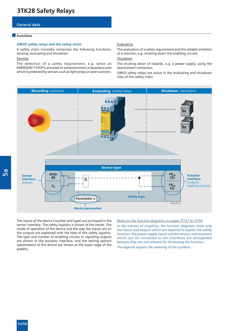
5a
5a/58
Functions
General data
SIRIUS safety relays and the safety chain
A safety chain normally comprises the following functions:sensing, evaluating and shutdown.
Sensing
The detection of a safety requirement, e.g. when anEMERGENCY-STOP is actuated or someone enters a hazardous areawhich is protected by sensors such as light arrays or laser scanners.
Evaluating
The evaluation of a safety requirement and the reliable initiationof a reaction, e.g. shutting down the enabling circuits.
Shutdown
The shutting down of hazards, e.g. a power supply, using thedownstream contactors.
SIRIUS safety relays are active in the evaluating and shutdownlinks of this safety chain.
The inputs of the device (number and type) are portrayed in thesensor interface. The safety logistics is shown at the center. Themode of operation of the device and the way the inputs act onthe outputs are explained with the help of this safety logistics.The type and number of enabling circuits or signaling outputsare shown in the actuator interface, and the setting options(parameters) of the device are shown at the lower edge of thegraphic.
��
������
������
�
����,��)��
��� ������
�����������
��� ������������
� ������������� ����������� ��������������
������������� ���������
�� ���������������� ������������������������ ������ ��������������
���!"�
#���������$
Notes on the function diagrams on pages 7/127 to 7/154
In the interest of simplicity, the function diagrams show onlythe inputs and outputs which are required to explain the safetyfunction. The power supply inputs and the sensors and actuatorswhich can be connected to the interfaces are disregardedbecause they are not relevant for illustrating the function.
The legends explain the meaning of the symbols.
3TK28 Safety Relays

5a
5a/59
With relay enabling circuits
Design
The 3TK28 21 to 28, 3TK28 30 and 3TK28 34 safety relays operatewith internal contactor relays with positively-driven contacts. Thecontacts of the controls comply with the requirement forpositively-driven operation laid down in ZH 1/457, Edition 2,1978. NO and NC contacts are not allowed to be closed at thesame time.
In a redundant circuit, operation of the internal controls ismonitored. If a safety relay fails, it will always switch to thede-energized and consequently safe state. The fault is detectedand the safety relay can no longer be switched on.
This product series is characterized by its space-saving width (22.5mm or 45 mm). The usual BIA, BG and SUVA approvals and testcertificates have been awarded.
Enabling contacts (FK)
Safety related operation must be performed by safe outputcontacts, known as enabling contacts. Enabling contacts arealways NO contacts and switch without delay.
Signaling contacts (MK)
NC contacts are used as signaling contacts but they are notpermitted to perform functions with relevance for safety. Anenabling contact can also be used as a signaling contact. Asignaling contact cannot, however, be used as an enablingcontact.
Delayed enabling contacts
Machine operating mechanisms that overrun for a long time mustbe externally braked in the event of danger. For this purpose, theenergy infeed for electrical braking can be maintained (StopCategory 1 according to EN 60204-1).
The basic units have off-delay enabling contacts in addition toinstantaneous enabling contacts. Delay time of between 0.5 and30 s are available with the different versions. A 3RP19 02 sealablecover can be fitted to protect against unauthorized adjustmentof the set delay time.
Expansion units
If the enabling contacts of the basic unit are inadequate,expansion units can be used. An expansion unit has 4 enablingcontacts.
Expansion units are not allowed to be operated separately insafety-related switching circuits; they must be combined with abasic unit. One enabling contact of the basic unit is required forconnecting an expansion unit. The category of a control systemwith expansion unit corresponds to that of the basic unit.
Mounting
The equipment is designed for snap-on mounting on a TH 35standard mounting rail according to EN 60715. Screw mountingis also possible for the devices by means of 2 additional3RP19 03 push-in lugs.
3TK28 Safety Relays

5a
5a/60
Functions
Basic units
3TK28 21 to 3TK28 28 (without 3TK28 26)
The devices 3TK28 21 to 3TK28 28 (without 3TK28 26) each haveone sensor input and a varying number of contactor relay enablingcircuits and signaling outputs. If the signal is no longer appliedto the sensor input, the enabling circuits are disconnectedimmediately or according to the set delay timed.
With relay enabling circuits
S 1 FK rel
NS
C0_
0067
9
FK rel
FK rel
MK rel
AS (NO)
(NO)
(NO)
(NC)
3TK28 21 basic unit
NS
C0_
0068
0
S 1 FK rel
FK rel
AS (NO)
(NO)
3TK28 22/3TK28 24 basic unit
NS
C0_
0068
1
S 1 FK rel
FK rel
ÜS (NO)
(NO)
3TK28 23 basic unit
NS
C0_
0068
2
S
1
FK
rel
FK
rel
FK
rel
MK
rel
MK
rel
AS/ÜS
AS/ÜS
(NO)
(NO)
(NO)
(NC)
(NC)
1-/2-channel
3TK28 25 basic unit
S
1
FK
rel
FK
rel
ÜS
(NO)
(NO)
3TK28 27 basic unit delayed
NS
C0_
0068
4
S
1
FK
rel
FK
rel
FK
rel
MK
rel
FK
rel
AS
tv
tv
(NO)
(NO)
(NC)
1-/2-channel
3TK28 28 basic unit delayed
)tv(NO
)tv(NO
Legend
Sensor interface
Sx: Sensor input
Safety logic
AS: Automatic start Device starts automatically once the enablingconditions are fulfilled. If a START button is integrated in thefeedback circuit, a manual start is also possible(up to Category 3 according to EN 954-1).
AS/ÜS: Automatic or monitored start depending on the parameterization
ÜS: Monitored start. Device does not start until after the enablingconditions are fulfilled and a start signal is issued.
Time delay, OFF-delay
Parameters
AS/ÜS: Automatic or monitored start depending on the parameterization
1-/2-channel: One-channel / two-channel sensor connection
Actuator interface
FKrel: Enabling circuit, relay contact (floating)
MKrel: Signaling circuit, relay contact (non-floating)
NC: NC contact
NO: NO contact
NOtv: NO contact, time-delayed
tv
3TK28 Safety Relays

5a
5a/61
With relay enabling circuits
Basic units
3TK28 26
The 3TK28 26 safety relay combines several functions in one unit.The sensor input S1 and the cascading input KAS are suitable forconnecting sensors with contacts, non-contact sensors (electronicsensors), safety mats and NC/NO magnetically operated switches.
DIP switches mounted on the front can be used to adapt thefunctions of the device to the functions required.
Expansion units
3TK28 30
The 3TK28 30 is activated through the power supply input A1.On the output side are four contactor relay enabling circuits. Ifthe signal is no longer applied to the input, the enabling circuitsare isolated immediately.
Legend
Sensor interface
Sx: Sensor input
A1: Power supply input as sensor input or cascading input
KAS/BS: Cascading input or normal switching duty..Normal switching duty: Connection of a PLCoutput for example. The enabling circuits and hence theconnected loads can then be operatedby the machine control. The safety function is on a higher level.
Safety logic
AS/ÜS: Automatic or monitored start depending on the parameterization
Parameters
1 to 8 see drawing
Actuator interface
FKrel: Enabling circuit, relay contact (floating)MKrel: Signaling circuit, relay contact (non-floating)NC: NC contactNO: NO contact
NS
C0_
0069
5a
&AS/ÜS
AS/ÜS
1 2 3 4 5 6 7 8
S3TK28 26 24 V DC instantaneous
1 with/without crossover detection2 2 NC/1 NC+1 NO evaluation3 1x2/2x1-channel4 10 ms/50 ms debounce time for cascading and
sensor input5 Sensor input monitored/automatic start6 Cascading input monitored/automatic start7 with/without starting check8 with/without automatic starting after mains failureSafety mats operation:1: ON, 2: OFF, 3: OFF, 4 to 6: unchanged
KAS/BS
S1
FKrel(NO)
MK rel(NC)
FKrel(NO)
FKrel(NO)
FKrel(NO)
MKel(NO)
MKel(NO)
NS
C0_
0071
3a
&
AS/ÜS
AS/ÜS
1 2 3 4 5
6
7
8
S3TK28 26 24 … 240 V AC/DC instantaneous
1
Safety mats operation:1: ON, 2: OFF, 3: OFF, 4 to 6: unchanged
with/without crossover detection2 2 NC/1 NC+1 NO evaluation3 1x2/2x1-channel4 10 ms/50 ms debounce time for cascading and
sensor input 5 Sensor input monitored/automatic start6 Cascading input monitored/automatic start7 with/without starting check8 with/without automatic starting after mains failure
KAS/BS
S1
FKrel(NO)
MK rel(NC)
FKrel(NO)
FKrel(NO)
FKrel(NO)
MKrel(NO)
A 1
NS
C0_
0068
5
FKrel(NO)
FKrel(NO)
FKrel(NO)
FKrel(NO)
3TK28 30 expansion unit
3TK28 Safety Relays

5a
5a/62
Technical specifications
With relay enabling circuits
3TK28 Safety Relays
Type 3TK28 21 3TK28 22 3TK28 23 3TK28 3TK28 3TK28 2524-..B0.0 24-.A.20
General data
Standards EN 60204-1, EN ISO 12100, EN 954-1, IEC 61508
Test certificates BG, SUVA , UL , CSA
Safety-oriented output contacts• Instantaneous FKrel 3 2 3• Time-delayed FKrel (tv) -- -- --
Safety-oriented semiconductor outputs• Instantaneous FKel --• Time-delayed FKel (tv) --
Signaling contacts MKrel 1 -- 2
Semiconductor signaling outputs MKrel --
Sensor inputs S 1
Cascading inputs KAS/BS --
Degree of protection acc. to EN 60529• Enclosures IP40• Terminals IP20
Shock resistance sine wave g/ms 8/10
Permissible mounting positions Any
Touch protection Finger-safeAcc. to DIN VDE 0106 Part 100 or EN 60900
Height mm 102: Screw terminals; 104: Spring-loaded terminals
Width mm 22.5
Depth mm 115
Weight g 0.240 0.460
Connection type Screw terminals• Terminal screw M 3 (standard screwdriver, size 2 and Pozidriv 2)• Solid mm2 1 x (0.5 ... 4) / 2 x (0.5 ... 2.5)• Finely stranded with end sleeve mm2 1 x (0.5 ... 2.5) / 2 x (0.5 ... 1.5)• AWG cables, solid or stranded AWG 2 x (24 ... 16)• Tightening torque Nm 0.8 … 1.2
Electrical specifications
Rated control supply voltage Us V 24 AC/DC 115/230 AC 24 AC/115/230,24 DC
Operating range• AC operation V 0.85 ... 1.1 × Us 0.85 ... 1.1×Us 0.85 ... 1.1 ×Us
• DC operation V 0.85 ... 1.2 × Us -- 0.85 ... 1.1 × Us
Measurement voltage V --
Response value Uresp mV --
Rated insulation voltage Ui• For control circuit V --• For outputs V 300
Rated impulse withstand voltage Uimp
• For control circuit V --• For outputs V 4000
Rated power W 1.5 3
Frequency ranges Hz 50/60
Rated operational current ΙΙΙΙΙe(relay outputs) at• AC-15 at 115 V A 5 6• AC-15 at 230 V A 5 6• DC-13 at 24 V A 5 6• DC-13 at 115 V A 0.2 0.2• DC-13 at 230 V A 0.1 0.1
Rated operational current ΙΙΙΙΙe(semiconductor outputs) at• DC-13 at 24 V A --• DC-13 at 230 V A --
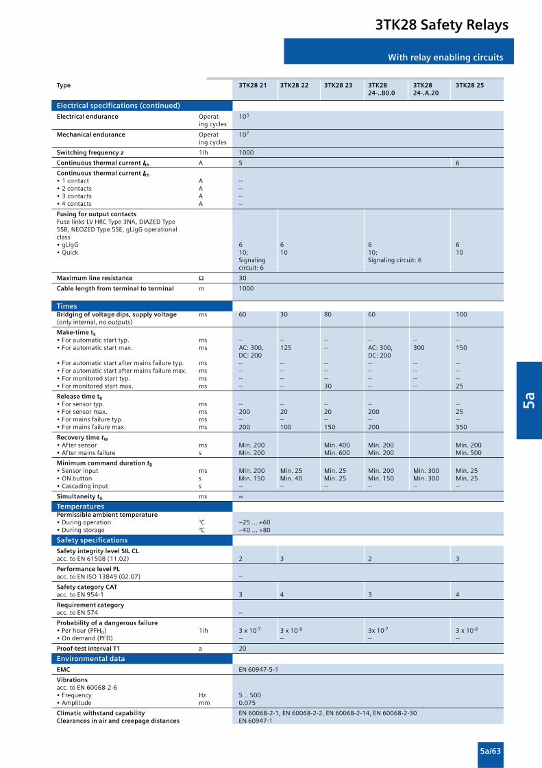
5a
5a/63
With relay enabling circuits
3TK28 Safety Relays
Type 3TK28 21 3TK28 22 3TK28 23 3TK28 3TK28 3TK28 2524-..B0.0 24-.A.20
Electrical specifications (continued)
Electrical endurance Operat- 105
ing cycles
Mechanical endurance Operat 107
ing cycles
Switching frequency z 1/h 1000
Continuous thermal current ΙΙΙΙΙth A 5 6
Continuous thermal current ΙΙΙΙΙth• 1 contact A --• 2 contacts A --• 3 contacts A --• 4 contacts A --
Fusing for output contactsFuse links LV HRC Type 3NA, DIAZED Type5SB, NEOZED Type 5SE, gL/gG operationalclass• gL/gG 6 6 6 6• Quick 10; 10 10; 10
Signaling Signaling circuit: 6circuit: 6
Maximum line resistance Ω 30
Cable length from terminal to terminal m 1000with Cu 1.5 mm2 and 150 nF/km
TimesBridging of voltage dips, supply voltage ms 60 30 80 60 100(only internal, no outputs)
Make-time tE• For automatic start typ. ms -- -- -- -- -- --• For automatic start max. ms AC: 300, 125 -- AC: 300, 300 150
DC: 200 DC: 200• For automatic start after mains failure typ. ms -- -- -- -- -- --• For automatic start after mains failure max. ms -- -- -- -- -- --• For monitored start typ. ms -- -- -- -- -- --• For monitored start max. ms -- -- 30 -- -- 25
Release time tR• For sensor typ. ms -- -- -- -- --• For sensor max. ms 200 20 20 200 25• For mains failure typ. ms -- -- -- -- --• For mains failure max. ms 200 100 150 200 350
Recovery time tW
• After sensor ms Min. 200 Min. 400 Min. 200 Min. 200• After mains failure s Min. 200 Min. 600 Min. 200 Min. 500
Minimum command duration tB
• Sensor input ms Min. 200 Min. 25 Min. 25 Min. 200 Min. 300 Min. 25• ON button s Min. 150 Min. 40 Min. 25 Min. 150 Min. 300 Min. 25• Cascading input s -- -- -- -- -- --
Simultaneity tG ms ∞TemperaturesPermissible ambient temperature• During operation °C –25 ... +60• During storage °C –40 ... +80
Safety specifications
Safety integrity level SIL CLacc. to EN 61508 (11.02) 2 3 2 3
Performance level PLacc. to EN ISO 13849 (02.07) --
Safety category CATacc. to EN 954-1 3 4 3 4
Requirement categoryacc. to EN 574 --
Probability of a dangerous failure• Per hour (PFHD) 1/h 3 x 10⁻⁷ 3 x 10⁻⁸ 3x 10⁻⁷ 3 x 10⁻⁸
• On demand (PFD) -- -- -- --
Proof-test interval T1 a 20
Environmental data
EMC EN 60947-5-1
Vibrationsacc. to EN 60068-2-6• Frequency Hz 5 .. 500• Amplitude mm 0.075
Climatic withstand capability EN 60068-2-1, EN 60068-2-2, EN 60068-2-14, EN 60068-2-30Clearances in air and creepage distances EN 60947-1

5a
5a/64
With relay enabling circuits
3TK28 Safety Relays
Type 3TK28 26-.BB40 3TK28 26-.CW30 3TK28 26-.BB41 3TK28 26-.CW31 3TK28 273TK28 26-.BB42 3TK28 26-.CW323TK28 26-.BB43 3TK28 26-.CW44
General data
Standards EN 60204-1, EN ISO 12100, EN 954-1, IEC 61508
Test certificates TÜV, UL , CSA BG, SUVA , UL ,CSA
Safety-oriented output contacts• Instantaneous FKrel 4 2• Time-delayed FKrel (tv) -- 2
Safety-oriented semiconductor outputs• Instantaneous FKel --• Time-delayed FKel (tv) --
Signaling contacts MKrel 1 2 3 1
Semiconductor signaling outputs MKrel 2 -- 2 --
Sensor inputs S 1
Cascading inputs KAS/BS 1 -
Degree of protection acc. to EN 60529• Enclosures IP40• Terminals IP20
Shock resistance sine wave g/ms 8/10
Permissible mounting positions Any
Touch protection Finger-safeAcc. to DIN VDE 0106 Part 100 or EN 60900
Height mm 106: Screw terminals; 108: Spring-loaded terminals
Width mm 45
Depth mm 116 115
Weight g 0.350 0.580
Connection type Screw terminals• Terminal screw M 3 (standard screwdriver, size 2 and Pozidriv 2)• Solid mm2 1 x (0.5 ... 4) / 2 x (0.5 ... 2.5)• Finely stranded with end sleeve mm2 1 x (0.5 ... 2.5) / 2 x (0.5 ... 1.5)• AWG cables, solid or stranded AWG 2 x (24 ... 16)• Tightening torque Nm 0.8 … 1.2
Electrical specifications
Rated control supply voltage Us V 24 AC/DC 24 ... 240AC/DC 24DC 24 ... 240AC/DC 24 DC24/115/230 AC
Operating range• AC operation V -- 0.9 ... 1.1 × Us 0.9 ... 1.1 × Us 0.85 ... 1.1 ×Us
• DC operation V 0.85 ... 1.2 × Us 0.9 ... 1.1 × Us 0.85 ... 1.2 × Us 0.9 ... 1.1 × Us 0.85 ... 1.1 × Us
Measurement voltage V --
Response value Uresp mV --
Rated insulation voltage Ui• For control circuit V --• For outputs V 300
Rated impulse withstand voltage Uimp• For control circuit V --• For outputs V 4000
Rated power W 3
Frequency ranges Hz 50/60
Rated operational current ΙΙΙΙΙe(relay outputs) at• AC-15 at 115 V A 13/14, 23/24, 13/14, 23/24, 13/14, 23/24, 13/14, 23/24, --
33/34, 43/44: 4 33/34, 43/44: 4 33/34, 43/44: 4 33/34, 43/44: 451/52: 3 51/52: 3 51/52: 3 51/52: 3
• AC-15 at 230 V A 13/14, 23/24, 13/14, 23/24, 13/14, 23/24, 13/14, 23/24, 13/14, 23/2433/34, 43/44: 4 33/34, 43/44: 4 47/48, 57/58: 4 33/34, 43/44: 4 47/48, 57/58: 451/52: 3 51/52: 3 31/32, 61/62: 3 51/52: 3 31/32, 61/62: 3
73/74: 1• DC-13 at 24 V A 13/14, 23/24, 13/14, 23/24, 13/14, 23/24, 13/14, 23/24, 13/14, 23/24: 5
33/34, 43/44: 4 33/34, 43/44: 4 47/48, 57/58: 4 47/48, 57/58: 4 47/48, 57/58: 251/52: 2 51/52: 2, 63/64: 1 31/32, 61/62: 2 31/32, 61/62: 2
73/74: 1• DC-13 at 115 V A 0.2 0.2 0.2 0.2 0.2• DC-13 at 230 V A 0.1 0.1 0.1 0.1 0.1
Rated operational current ΙΙΙΙΙe(semiconductor outputs) at• DC-13 at 24 V A 64, 75: 0.5 -- 74, 84: 0.5 -- --• DC-13 at 230 V A -- -- -- -- --

5a
5a/65
With relay enabling circuits
3TK28 Safety Relays
Type 3TK28 26-.BB40 3TK28 26-.CW30 3TK28 26-.BB41 3TK28 26-.CW31 3TK28 273TK28 26-.BB42 3TK28 26-.CW323TK28 26-.BB43 3TK28 26-.CW44
Electrical specifications (continued)
Electrical endurance Operat- -- 105
ing cycles
Mechanical endurance Operat 107
ing cycles
Switching frequency z 1/h 2000 1000
Continuous thermal current ΙΙΙΙΙth A Summation current max. 125
Continuous thermal current ΙΙΙΙΙth• 1 contact A 4• 2 contacts A 4• 3 contacts A 3• 4 contacts A 3
Fusing for output contactsFuse links LV HRC Type 3NA, DIAZED Type5SB, NEOZED Type 5SE, gL/gG operational class• gL/gG 4 6 (control)• Quick 6 Voltage: 2
10
Maximum line resistance Ω 1000 30
Cable length from terminal to terminal m 2000 1000with Cu 1.5 mm2 and 150 nF/km
Times
Bridging of voltage dips, supply voltage ms Min. 10 30(only internal, no outputs)
Make-time tE• For automatic start typ. ms 50 + debounce time --• For automatic start max. ms 50 + debounce time --• For automatic start after mains failure typ. ms Approx. 8000 starting time Approx. 8000
starting time• For automatic start after mains failure max. ms Approx. 8000 starting time Approx. 8000
staring time• For monitored start typ. ms 50 + debounce time --• For monitored start max. ms 50 + debounce time 80
Release time tR• For sensor typ. ms 50 + deb. time 50 + deb. time -- -- --• For sensor max. ms -- -- 50+ debounce 50+ debounce ≤ 30 adjustable• For mains failure typ. ms 75 -- 75 -- --• For mains failure max. ms 125 300 125 320 100
Recovery time tW
• After sensor ms Min. 250 Min. 250 Min. 250 After time haselapsed
• After mains failure s Min. 200 Min. 600 Min. 200 Min. 200
Minimum command duration tB
• Sensor input ms 30 Min. 25• ON button s 0.2 ... 5 Min. 25• Cascading input s -- --
Simultaneity tG ms ∞Temperatures
Permissible ambient temperature• During operation °C –25 ... +60• During storage °C –40 ... +80
Safety specifications
Safety integrity level SIL CL 3 Stop cat. 0: 3acc. to EN 61508 (11.02) Stop cat. 1: 2
Performance level PL acc. to EN ISO 13849 (02.07) e --
Safety category CAT 4 Stop cat. 0: 4acc. to EN 954-1 Stop cat. 1: 3
Requirement category acc. to EN 574 --
Probability of a dangerous failure• Per hour (PFHD) 1/h 7.8 x 10⁻⁹ 7.8 x 10⁻⁹ 7.8 x 10⁻⁹ 7.8 x 10⁻⁹ 3 x 10⁻⁸
• On demand (PFD) -- -- -- --Proof-test interval T1 a 20
Environmental data
EMC EN 60947-5-1
Vibrations acc. to EN 60068-2-6• Frequency Hz 5 .. 500• Amplitude mm 0.075
Climatic withstand capability EN 60068-2-1, EN 60068-2-2, EN 60068-2-14, EN 60068-2-30
Clearances in air and creepage distances EN 60947-1
1) Time-delayed enabling circuit: ≤ 300 ms adjustable.

5a
5a/66
With relay enabling circuits
3TK28 Safety Relays
Type 3TK28 26-.BB40 3TK28 26-.CW30 3TK28 26-.BB41 3TK28 26-.CW31 3TK28 273TK28 26-.BB42 3TK28 26-.CW323TK28 26-.BB43 3TK28 26-.CW44
General data
Standards EN 60204-1, EN ISO 12100, EN 954-1, IEC 61508
Test certificates TÜV, UL , CSA BG, SUVA , UL ,CSA
Safety-oriented output contacts• Instantaneous FKrel 4 2• Time-delayed FKrel (tv) -- 2
Safety-oriented semiconductor outputs• Instantaneous FKel --• Time-delayed FKel (tv) --
Signaling contacts MKrel 1 2 3 1
Semiconductor signaling outputs MKrel 2 -- 2 --
Sensor inputs S 1
Cascading inputs KAS/BS 1 -
Degree of protection acc. to EN 60529• Enclosures IP40• Terminals IP20
Shock resistance sine wave g/ms 8/10
Permissible mounting positions Any
Touch protection Finger-safeAcc. to DIN VDE 0106 Part 100 or EN 60900
Height mm 106: Screw terminals; 108: Spring-loaded terminals
Width mm 45
Depth mm 116 115
Weight g 0.350 0.580
Connection type Screw terminals• Terminal screw M 3 (standard screwdriver, size 2 and Pozidriv 2)• Solid mm2 1 x (0.5 ... 4) / 2 x (0.5 ... 2.5)• Finely stranded with end sleeve mm2 1 x (0.5 ... 2.5) / 2 x (0.5 ... 1.5)• AWG cables, solid or stranded AWG 2 x (24 ... 16)• Tightening torque Nm 0.8 … 1.2
Electrical specifications
Rated control supply voltage Us V 24 AC/DC 24 ... 240AC/DC 24DC 24 ... 240AC/DC 24 DC24/115/230 AC
Operating range• AC operation V -- 0.9 ... 1.1 × Us 0.9 ... 1.1 × Us 0.85 ... 1.1 ×Us
• DC operation V 0.85 ... 1.2 × Us 0.9 ... 1.1 × Us 0.85 ... 1.2 × Us 0.9 ... 1.1 × Us 0.85 ... 1.1 × Us
Measurement voltage V --
Response value Uresp mV --
Rated insulation voltage Ui• For control circuit V --• For outputs V 300
Rated impulse withstand voltage Uimp• For control circuit V --• For outputs V 4000
Rated power W 3
Frequency ranges Hz 50/60
Rated operational current ΙΙΙΙΙe
(relay outputs) at• AC-15 at 115 V A 13/14, 23/24, 13/14, 23/24, 13/14, 23/24, 13/14, 23/24, --
33/34, 43/44: 4 33/34, 43/44: 4 33/34, 43/44: 4 33/34, 43/44: 451/52: 3 51/52: 3 51/52: 3 51/52: 3
• AC-15 at 230 V A 13/14, 23/24, 13/14, 23/24, 13/14, 23/24, 13/14, 23/24, 13/14, 23/2433/34, 43/44: 4 33/34, 43/44: 4 47/48, 57/58: 4 33/34, 43/44: 4 47/48, 57/58: 451/52: 3 51/52: 3 31/32, 61/62: 3 51/52: 3 31/32, 61/62: 3
73/74: 1• DC-13 at 24 V A 13/14, 23/24, 13/14, 23/24, 13/14, 23/24, 13/14, 23/24, 13/14, 23/24: 5
33/34, 43/44: 4 33/34, 43/44: 4 47/48, 57/58: 4 47/48, 57/58: 4 47/48, 57/58: 251/52: 2 51/52: 2, 63/64: 1 31/32, 61/62: 2 31/32, 61/62: 2
73/74: 1• DC-13 at 115 V A 0.2 0.2 0.2 0.2 0.2• DC-13 at 230 V A 0.1 0.1 0.1 0.1 0.1
Rated operational current ΙΙΙΙΙe
(semiconductor outputs) at• DC-13 at 24 V A 64, 75: 0.5 -- 74, 84: 0.5 -- --• DC-13 at 230 V A -- -- -- -- --

5a
5a/67
With relay enabling circuits
3TK28 Safety Relays
Type 3TK28 26-.BB40 3TK28 26-.CW30 3TK28 26-.BB41 3TK28 26-.CW31 3TK28 273TK28 26-.BB42 3TK28 26-.CW323TK28 26-.BB43 3TK28 26-.CW44
Electrical specifications (continued)
Electrical endurance Operat- -- 105
ing cycles
Mechanical endurance Operat 107
ing cycles
Switching frequency z 1/h 2000 1000
Continuous thermal current ΙΙΙΙΙth A Summation current max. 125
Continuous thermal current ΙΙΙΙΙth• 1 contact A 4• 2 contacts A 4• 3 contacts A 3• 4 contacts A 3
Fusing for output contactsFuse links LV HRC Type 3NA, DIAZED Type5SB, NEOZED Type 5SE, gL/gG operational class• gL/gG 4 6 (control)• Quick 6 Voltage: 2
10
Maximum line resistance Ω 1000 30
Cable length from terminal to terminal m 2000 1000with Cu 1.5 mm2 and 150 nF/km
Times
Bridging of voltage dips, supply voltage ms Min. 10 30(only internal, no outputs)
Make-time tE• For automatic start typ. ms 50 + debounce time --• For automatic start max. ms 50 + debounce time --• For automatic start after mains failure typ. ms Approx. 8000 starting time Approx. 8000
starting time• For automatic start after mains failure max. ms Approx. 8000 starting time Approx. 8000
staring time• For monitored start typ. ms 50 + debounce time --• For monitored start max. ms 50 + debounce time 80
Release time tR• For sensor typ. ms 50 + deb. time 50 + deb. time -- -- --• For sensor max. ms -- -- 50+ debounce 50+ debounce ≤ 30 adjustable• For mains failure typ. ms 75 -- 75 -- --• For mains failure max. ms 125 300 125 320 100
Recovery time tW
• After sensor ms Min. 250 Min. 250 Min. 250 After time haselapsed
• After mains failure s Min. 200 Min. 600 Min. 200 Min. 200
Minimum command duration tB
• Sensor input ms 30 Min. 25• ON button s 0.2 ... 5 Min. 25• Cascading input s -- --
Simultaneity tG ms ∞Temperatures
Permissible ambient temperature• During operation °C –25 ... +60• During storage °C –40 ... +80
Safety specifications
Safety integrity level SIL CL 3 Stop cat. 0: 3acc. to EN 61508 (11.02) Stop cat. 1: 2
Performance level PL acc. to EN ISO 13849 (02.07) e --
Safety category CAT 4 Stop cat. 0: 4acc. to EN 954-1 Stop cat. 1: 3
Requirement category acc. to EN 574 --
Probability of a dangerous failure• Per hour (PFHD) 1/h 7.8 x 10⁻⁹ 7.8 x 10⁻⁹ 7.8 x 10⁻⁹ 7.8 x 10⁻⁹ 3 x 10⁻⁸
• On demand (PFD) -- -- -- --Proof-test interval T1 a 20
Environmental data
EMC EN 60947-5-1
Vibrations acc. to EN 60068-2-6• Frequency Hz 5 .. 500• Amplitude mm 0.075
Climatic withstand capability EN 60068-2-1, EN 60068-2-2, EN 60068-2-14, EN 60068-2-30
Clearances in air and creepage distances EN 60947-1
1) Time-delayed enabling circuit: ≤ 300 ms adjustable.

5a
5a/68
With relay enabling circuits
3TK28 Safety Relays
Type 3TK28 26-.BB40 3TK28 26-.CW30 3TK28 26-.BB41 3TK28 26-.CW31
General data
Standards EN 60204-1, EN 60204-1,EN ISO 12100, EN ISO 12100,EN 954-1, EN 954-1,IEC 61508 IEC 61508
IEC 574
Test certificates BG, SUVA , UL , CSA, TÜV
Safety-oriented output contacts• Instantaneous FKrel 2 4 2 4• Time-delayed FKrel (tv) 2 -- -- --
Safety-oriented semiconductor outputs• Instantaneous FKel --• Time-delayed FKel (tv) --
Signaling contacts MKrel 1 2 --
Semiconductor signaling outputs MKrel --
Sensor inputs S 1 -- 1
Cascading inputs KAS/BS --
Degree of protection acc. to EN 60529• Enclosures IP40 IP20• Terminals IP20 IP20
Shock resistance sine wave g/ms 8/10
Permissible mounting positions Any
Touch protection Finger-safeAcc. to DIN VDE 0106 Part 100 or EN 60900
Height mm 106 (3TK28 30: 102): Screw terminals; 108 (3TK28 30: 104): Spring-loaded terminals
Width mm 45 22.5 45
Depth mm 115
Weight g 0.580 0.260 0.450 0.500
Connection type Screw terminals• Terminal screw M 3 (standard screwdriver, size 2 and Pozidriv 2)• Solid mm2 1 x (0.5 ... 4) / 2 x (0.5 ... 2.5)• Finely stranded with end sleeve mm2 1 x (0.5 ... 2.5) / 2 x (0.5 ... 1.5)• AWG cables, solid or stranded AWG 2 x (24 ... 16)• Tightening torque Nm 0.8 … 1.2
Connection type Spring-loaded terminals
• Solid mm2 2 x (0.25 ... 1.5)• Finely stranded, with end sleeves acc. to DIN 46228 mm2 2 x (0.25 ... 1.0)• Finely stranded mm2 2 x (0.25 ... 1.5)• Stripped length mm 10
Electrical specifications
Rated control supply voltage Us V 24 ... 240AC/115/230
Operating range• AC operation V 0.85 ... 1.1 × Us 0.85 ... 1.1 ×Us 0.85 ... 1.1 × Us
• DC operation V 0.85 ... 1.1 × Us 0.85 ... 1.1 × Us 0.85 ... 1.1 × Us
Measurement voltage V --
Response value Uresp mV --
Rated insulation voltage Ui• For control circuit V --• For outputs V 300
Rated impulse withstand voltage Uimp• For control circuit V --• For outputs V 4000
Rated power W 3 2 3
Frequency ranges Hz 50/60
Rated operational current ΙΙΙΙΙe
(relay outputs) at• AC-15 at 115 V A -- -- -- --• AC-15 at 230 V A 13/14, 23/24: 5 5 5 23/24, 33/34, 41/42: 5
47/48, 57/58: 3 5 13/14: 3• DC-13 at 24 V A 13/14, 23/24: 5 5 5 23/24, 33/34, 41/42: 5
47/48, 57/58: 3 5 13/14: 3• DC-13 at 115 V A 0.2 0.2 0.2 0.2• DC-13 at 230 V A 0.1 0.1 0.1 0.1
Rated operational current ΙΙΙΙΙe(semiconductor outputs) at• DC-13 at 24 V A --• DC-13 at 230 V A --

5a
5a/69
With relay enabling circuits
Type 3TK28 26-.BB40 3TK28 26-.CW30 3TK28 26-.BB41 3TK28 26-.CW31
Electrical specifications (continued)
Electrical endurance Operat- 105
ing cycles
Mechanical endurance Operat 107
ing cycles
Switching frequency z 1/h 1000
Continuous thermal current ΙΙΙΙΙth A 5 5 5
Continuous thermal current ΙΙΙΙΙth• 1 contact A --• 2 contacts A --• 3 contacts A --• 4 contacts A --
Fusing for output contactsFuse links LV HRC Type 3NA, DIAZED Type5SB, NEOZED Type 5SE, gL/gG operational class• gL/gG 6, control voltage: 2 6 6, control voltage: 2• Quick 10 10 10
Maximum line resistance Ω 30 --
Cable length from terminal to terminal m 1000 3TK28 30-.CB30:1000 1000 --with Cu 1.5 mm2 and 150 nF/km 3TK28 30-.AJ20: 300
3TK28 30-.AJ20: 80
Times
Bridging of voltage dips, supply voltage ms 30 3TK28 30-.CB30:10 40(only internal, no outputs) 3TK28 30-.A.20:35
Make-time tE• For automatic start typ. ms -- -- -- --• For automatic start max. ms 80 3TK28 30-.CB30: 30 100 50
3TK28 30-.A.20:200-- -- -- --
• For automatic start after mains failure typ. ms -- 3TK28 30-.CB30: 30 -- --3TK28 30-.A.20:200
• For automatic start after mains failure max. ms• For monitored start typ. ms -- -- -- --• For monitored start max. ms -- -- -- --
Release time tR• For sensor typ. ms -- -- -- --• For sensor max. ms Up to 30 adjustable -- 20 50• For mains failure typ. ms -- -- -- --• For mains failure max. ms 100 3TK28 30-.CB20: 25 -- --
3TK28 30-.A.20: 80
Recovery time tW• After sensor ms After time has -- Min 250 Min. 250
elapsed• After mains failure s Min. 1 3TK28 30-.CB20: 50 -- --
3TK28 30-.A.20: 120
Minimum command duration tB
• Sensor input ms Min. 25 --• ON button s Min. 25 --• Cascading input s -- --
Simultaneity tG ms ∞Temperatures
Permissible ambient temperature• During operation °C –25 ... +60• During storage °C –40 ... +80
Safety specifications
Safety integrity level SIL CL Stop cat. 0: 3 3acc. to EN 61508 (11.02) Stop cat. 1: 2
Performance level PL acc. to EN ISO 13849 (02.07) --
Safety category CAT Stop cat. 0: 4 As basic unit 4 As basic unitacc. to EN 954-1 Stop cat. 1: 3
Requirement category acc. to EN 574 -- -- Type III C As basic unit
Probability of a dangerous failure• Per hour (PFHD) 1/h 3 x 10⁻⁸ 2.6 x 10⁻⁹ 3 x 10⁻⁸
• On demand (PFD) -- -- -- --
Proof-test interval T1 a 20
Environmental data
EMC EN 60947-5-1
Vibrations acc. to EN 60068-2-6• Frequency Hz 5 .. 500• Amplitude mm 0.075
Climatic withstand capability EN 60068-2-1, EN 60068-2-2, EN 60068-2-14, EN 60068-2-30
Clearances in air and creepage distances EN 60947-1
3TK28 Safety Relays

5a
5a/70
With relay enabling circuits
Dimenstional drawings
3TK28 21 to 3TK28 24, 3TK28 30 with screw terminals
3TK28 25 up to 3TK28 28, 3TK28 34, 3TK28 35with screw terminals
3TK28 21 to 3TK28 24, 3TK28 30with spring-loaded terminals
3TK28 25 up to 3TK28 28, 3TK28 34, 3TK28 35
with spring-loaded terminals
22,515
NSC0_00671b
120
8768 74110
11594
655
74
102
83
1)
139
9168 118
NSC0_00672b
3745
11594
65
74
102
106
83
5
1)
5
75
3745
73
98 139
118
102
115
84 108
NSC0_00673b
1)
22,515
NSC0_00674b
120
9475 74110
1155
72,5
103
84
1)
1) For standard mounting rail TH 35 according to EN 60715.
Schematics
3TK28 21 3TK28 23 3TK28 24
A1L/+
NS
B0_
0185
8a
Y1RF1.1
Y2RF1.2
13FK1.1
23FK2.1
N/-A2
MK1.141
MK1.242
FK1.214
FK2.224
FK3.234
=
~
33FK3.1
Logic
A1L/+
NS
B0_
0185
9
Y11S1.1
Y12S1.2
13RF1.1
13FK1.1
N/-A2
S2.1Y21
S2.2Y22
RF1.214
FK1.214
FK2.224
=
~
23FK2.1
Logic
A1L/+
NS
B0_
0186
0
Y1RF1.1
Y2RF1.2
13FK1.1
N/-A2
FK1.214
FK2.224
=
~
23FK2.1
Logic
LegendFKx.x: Enabling circuitsSx.x: Sensor terminals (test connectors)RFx.x: Feedback circuit terminalsMKx.x: Indicating circuit terminalsPE: PE conductor terminalTx: Test signal terminal
ON: Start signal terminal1-/2-kan: Parameter terminal switchover, one/two-channelQS: Parameter terminal with crossover monitoring (ON/OFF)AS/ÜS: Parameter terminal switchover, automatic/monitored startKAS/BS: Terminal, cascading input
3TK28 Safety Relays

5a
5a/71
With relay enabling circuits
Schematics
3TK28 25
3TK28 26-.BB40
3TK28 26-.CW30
3TK28 26-.BB4.
3TK28 26-.CW3.
3TK28 27, 3TK28 28
3TK28 30
LegendFKx.x: Enabling circuitsSx.x: Sensor terminals (test connectors)RFx.x: Feedback circuit terminalsMKx.x: Indicating circuit terminalsPE: PE/ground conductor terminalTx: Test signal terminalON: Start signal terminal1-/2-kan: Parameter terminal switchover, one/two-channelQS: Parameter terminal with crossover monitoring (ON/OFF)AS/ÜS: Parameter terminal switchover, automatic/monitored startKAS/BS: Terminal, cascading input
A1L/+
NS
B0_
0186
1a
Y11S1.1
Y12S1.2
Y21S1.3
Y22S1.4
N/-A2
PEPE
RF1.1Y33
RF1.2Y34
FK2.224
FK3.234
=
~
AS/ÜS1.1Y43
MK1.242
MK2.252
13FK1.1
33FK3.1
AS/ÜS1.2Y44
FK1.214
23FK2.1
41MK1.1
51MK2.1
Y101-/2-kan
Logic
A1DC24 V
NS
B0_
0186
2a
Y12S1.1
T1T1
Y33EIN
T3T3
0VA2
TST2
FK2.2 FK3.2
=
=
S1.2Y22
FK1.2 FK4.2 MK1.2
1KAS/BS
43FK4.1
51MK1.1
RFY34
MK174
MK264
13FK1.1
23FK2.1
33FK3.1
Logic
A1DC24 V
NS
B0_
0186
3a
Y12S1.1
T1T1
Y33EIN
T3T3
0VA2
TST2
FK2.224
FK3.234
=
~
S1.2Y22
FK1.214
FK4.244
MK1.252
1KAS/BS
43FK4.1
51MK1.1
RFY34
MK1.163
MK1.264
13FK1.1
23FK2.1
33FK3.1
Logic
A1DC24 V
NS
B0_
0186
4a
Y12S1.1
T1T1
Y33EIN
T3T3
0VA2
TST2
=
=
S1.2Y22
1KAS/BS
57FK4.1
61MK2.1
RFY34
MK174
MK284
13FK1.1
23FK2.1
47FK3.1
FK2.224
FK3.248
FK1.214
FK4.258
MK2.262
MK1.232
31MK1.1
Logic
A1DC24 V
NS
B0_
0186
5a
Y12S1.1
T1T1
Y33EIN
T3T3
0VA2
TST2
=
~
S1.2Y22
1KAS/BS
57FK4.1
61MK2.1
RFY34
MK1.173
MK1.274
13FK1.1
23FK2.1
47FK3.1
FK2.224
FK3.248
FK1.214
FK4.258
MK2.262
MK1.232
31MK1.1
Logic
A1L/+
NS
B0_
0186
6a
Y11S1.1
Y12S1.2
Y21S1.3
Y22S1.4
N/-A2
PEPE
RF1.1Y33
RF1.2Y34
FK2.224
FK3.234
=
~
MK1.242
MK2.252
13FK1.1
33FK3.1
FK1.214
23FK2.1
41MK1.1
51MK2.1
Y101-/2-kan
Logic
A1L/+
NS
B0_
0186
7a
33FK3.1
43FK4.1
N/-A2
FK2.123
MK1.252
FK3.234
FK4.244
=
~
51MK1.1
FK2.224
13FK1.1
14FK1.2
Logic
3TK28 Safety Relays

5a
5a/72
With contactor relay enabling circuits
Design
The solid-state safety relays can be used in EMERGENCY-STOPdevices according to EN 418 and in safety circuits according toEN 60204-1 (11.98), for example, for moving covers andprotective doors. Depending on the device type and the externalcircuit, the maximum category that can be achieved is Category4 of EN 954-1 or SIL 3 according to IEC 61508.
With these devices, solid-state safety relays are connected withcontactor relays. The combination is supplied as a complete unit,fully wired up and tested, for snapping onto a standard mountingrail. This unit combines the advantages of a solid-state safetyrelay and those of contactor relays with positively-driven contactsin a single device. It has been certified by the appropriateauthorities as a complete unit.
Basic units, Category 3
The 3TK28 50, 3TK28 51 and 3TK28 52 solid-state safety relayshave two contactor relays snapped onto the safety solid-stateunit as floating switching blocks. Three LEDs indicate theoperating state and the function. During operation, all internalcircuit elements are monitored cyclically for faults. Up to Category3 according to EN 954-1 is achieved, depending on the externalcircuit.
Basic units, Category 4
The 3TK28 53 solid-state safety relay has two contactor relayssnapped onto the safety solid-state units as floating switchingblocks, as well as a safe solid-state output, a safe input forcascading and one input for normal switching duty. Three LEDsindicate the operating state and the function.
During start-up, the device runs through a self-test in which theinternal electronics are checked for correct functioning. Duringoperation, all internal circuit elements are monitored cyclicallyfor faults.
Expansion units, namely 3TK28 30, 3TK28 56, 3TK28 57, 3RA711 to 3RA7 14, as well as external actuators or loads can beconnected using the safe solid-state output (terminal 2).Cascading with the 3TK28 41, 3TK28 42, 3TK28 45 and 3TK2853 safety relays as well as with the 3RA7 11 load feeder is alsopossible using the safe solid-state output (terminal 2).
Mounting
For snap-on mounting on TH 35 standard mounting rail accordingto EN 60715. Screw mounting is also possible for the devices bymeans of 2 additional 3RP19 03 push-in lugs.
Function
Basic units
3TK28 50 to 3TK28 52
The devices 3TK28 50 to 3TK28 52 each have one sensor inputand a varying number of contactor relay enabling circuits andsignaling outputs. If the signal is no longer applied to the sensorinput, the enabling circuits are isolated immediately.
NS
C0_
0068
9a
S
1
FK
hs
FK
hs
FK
hs
(NO)
(NO)
(NO)
3TK28 50 basic unit
1-/2-channel
AS/ÜS
AS/ÜS
NS
C0_
0069
0a
S1FKhs
FKhs
MKhs
AS/ÜS
AS/ÜS (NO)
(NO)
(NC)
3TK28 51 basic unit
1-/2-channel
NS
C0_
0069
1a
S
1
FK
hs
FK
hs
FK
hs
FK
hs
FK
hs
MK
hs
FK
hs
AS/ÜS
AS/ÜS (NO)
(NO)
(NO)
(NO)
(NO)
(NO)
(NO)
3TK28 52 basic unit
1-/2-channel
Legend
Sensor interface
Sx: Sensor input
Safety logic
AS/ÜS: Automatic or monitored start depending on theparameterization
Parameters
1-/2-channel: One-channel / two-channel sensor connectionAS/ÜS: Automatic or monitored start depending on the
parameterization
Actuator interface
FKhs: Enabling circuit, contactor relay (floating)MKhs: Signaling circuit, contactor relay (floating)NO: NO contactNC: NC contact
3TK28 Safety Relays

5a
5a/73
With contactor relay enabling circuits
Basic units
3TK28 53
The 3TK28 53 has one sensor input and one input for normalswitching duty and one cascading input. On the output side is avarying number of solid-state enabling circuits or contactor relayenabling circuits. If the signal is no longer applied to one of theinputs, the enabling circuits are isolated immediately. Autostart ormonitored start can be selected in the parameterization.
LegendSensor interfaceSx: Sensor inputKAS/BS: Cascading input or normal switching duty.
Normal switching duty: Connection of a PLC output forexample. The enabling circuits and hence the connectedloads can then be operated by the machine control.The safety function is on a higher level.
Safety logicAS: Automatic start. Device starts automatically once the
enabling conditions are fulfilled. If a START button isintegrated in the feedback circuit, a manual start is alsopossible (up to Category 3 according to EN 954-1).
AS/ÜS: Automatic or monitored start depending on theparameterization
ParametersQS: With or without crossover monitoringAS/ÜS: Automatic or monitored start depending on the
parameterization
Time delay, OFF-delay
Actuator interfaceFKel: Enabling circuit, solid-state (non-floating)FKhs: Enabling circuit, contactor relay (floating)MKhs: Signaling circuit, contactor relay (floating)NO: NO contactNOtv: NO contact, time-delayedNC: NC contact
Expansion units
3TK28 56 and 3TK28 57
The 3TK28 56 and 3TK28 57 devices each have one one input fornormal switching duty and one cascading input. On the outputside is a varying number number of solid-state enabling circuits orcontactor relay enabling circuits and signaling outputs. If thesignal is no longer applied to one of the inputs, the enabling circuitsare isolated immediately or according to the set delay time.
NS
C0_
0069
2
BS
KAS
S
1
FK
hs (NO)
FK
hs (NO)
FK
el (NO)
FK
hs (NO)
AS/ÜS
AS
&
AS/ÜS
QS
AS/ÜS
3TK28 53 basic unit
NS
C0_
0069
3
BS
KAS
FK
hs
FK
hs
FK
hs
FK
hs
FK
hs
FK
hs
FK
el
MK
hs
&
( NO)
(NO)
(NO)
(NO)
(NO)
(NO)
(NO)
(NC)
3TK28 56 expansion unit instantaneous
tv
NS
C0_
0069
4
BS
KAS
FK
hs
FK
hs
FK
hs
FK
el
&
tv
tv
tv
tv(NO
(NO
(NO)
(NO
)
)tv
3TK28 57 expansion unit delayed
tv)
3TK28 Safety Relays

5a
5a/74
With contactor relay enabling circuits
Technical specifications
3TK28 Safety Relays
Type 3TK28 50 3TK28 51 3TK28 52 3TK28 53 3TK28 53-0AB1 3TK28 56 3TK28 57
General data
Standards EN 60204-1, EN ISO 12100, EN 954-1, IEC 61508
Test certificates TÜV, UL, CSA
Safety-oriented output contacts• Instantaneous FKrel 3 2 6 3 6 3• Time-delayed FKrel (tv) -- -- -- -- -- --
Safety-oriented semiconductor outputs• Instantaneous FKel -- 1• Time-delayed FKel (tv) -- --
Signaling contacts MKrel -- 1 -- 1 --
Semiconductor signaling outputs MKrel --
Sensor inputs S 1 --
Cascading inputs KAS/BS -- 2
Degree of protection acc. to EN 60529• Enclosures IP20• Terminals IP20
Shock resistance sine wave g/ms 5/11 8/10 and 15 /5
Permissible mounting positions Any
Touch protection Finger-safeAcc. to DIN VDE 0106 Part 100 or EN 60900
Height mm 89
Width mm 90
Depth mm 112 150 112 150 112
Weight g 0.850 0.750
Connection type Screw terminals• Terminal screw M 3 (standard screwdriver, size 2 and Pozidriv 2)• Solid mm2 1 x (0.2 ... 2.5) / 2 x (0.2 ... 1.0)• Finely stranded with end sleeve mm2 1 x (0.25 ... 2.5) / 2 x (0.25 ... 1.0)• AWG cables, solid or stranded AWG 2 x (24 ... 12)• Tightening torque Nm 0.8 … 1.2
Electrical specifications
Rated control supply voltage Us V 24 DC, 24/115/230 AC 24 DC
Measurement voltage V --
Response value Uresp mV --
Operating range• AC operation V 0.9 ... 1.15 x Us --• DC operation V 0.85 ... 1.1 × Us 0.85 ... 1.1 × Us
Rated insulation voltage Ui
• For control circuit V 50• For outputs V 690
Rated impulse withstand voltage Uimp• For control circuit V 500• For outputs V 6000
Rated power at Us W 8.5
Frequency ranges Hz 50/60 --
Rated operational current ΙΙΙΙΙe(relay outputs) at• AC-15 at 115 V A -- -- -- --• AC-15 at 230 V A 6 6 -- --• DC-13 at 24 V A 10 10, 10 10,
Auxiliary Auxiliaryswitch switchblcoks: 6 blcoks: 6
• DC-13 at 115 V A -- -- -- --• DC-13 at 230 V A -- -- -- --
Rated operational current ΙΙΙΙΙe
(semiconductor outputs) at• DC-15 at 24 V A --• DC-15 at 230 V A --

5a
5a/75
With contactor relay enabling circuits
3TK28 Safety Relays
Type 3TK28 50 3TK28 51 3TK28 52 3TK28 53 3TK28 53-0AB1 3TK28 56 3TK28 57
Electrical specifications (continued)
Electrical endurance Operat- See "3RH1 Characteristic Curves"ing cycles
Mechanical endurance Operat 3 x 10⁷
ing cycles
Switching frequency z 1/h 103
Continuous thermal current ΙΙΙΙΙth A --
Continuous thermal current ΙΙΙΙΙth• 1 contact A --• 2 contacts A --• 3 contacts A --• 4 contacts A --
Fusing for output contactsFuse links LV HRC Type 3NA, DIAZED Type5SB, NEOZED Type 5SEclass• gL/gGt A 10• Quick A --
Maximum line resistance Ω 250 500
Cable length from terminal to terminal m 2000with Cu 1.5 mm2 and 150 nF/km
Times
Bridging of voltage dips, supply ms 5voltage (only internal, no outputs)
Make-time tE• For automatic start typ. ms 100 60 --• For automatic start max. ms 200 100 --• For automatic start after mains failure typ. ms 350 6000 6000• For automatic start after mains failure max.ms 500 7000 7000• For monitored start typ. ms 60 60 --• For monitored start max. ms 100 100 --
Release time tR• For sensor typ. ms 30 50 --• For sensor max. ms 50 60 300
adjustable• For mains failure typ. ms 100 120 120• For mains failure max. ms 120 120 120
Recovery time tW
• After sensor ms 20 500• After mains failure s 0.02 7
Minimum command duration tB
• Sensor input ms 20 45 --• ON button s 20 0.2 ... 5 --• Cascading input s 20 45 45
Simultaneity tG ms ∞Temperatures
Permissible ambient temperature• During operation °C –25 ... +60• During storage °C –40 ... +80
Safety specifications
Safety integrity level SIL CLacc. to EN 61508 (11.02) 2 3
Performance level PLacc. to EN ISO 13849 (02.07) d e --
Safety category CATacc. to EN 954-1 3 4 As basic unit
Requirement categoryacc. to EN 574 --
Probability of a dangerous failure• Per hour (PFHD) 1/h 1.3 x 10⁻⁸ 1.4 x 10⁻⁸ 1.6x 10⁻⁸ 5 x 10-11 9.8 x 10⁻¹¹
• On demand (PFD) -- -- -- -- -- --
Proof-test interval T1 a 10
Environmental data
EMC IEC 60947-5-1,IEC 60000-4-3,IEC 60000-4-5,IEC 60000-4-6
Vibrations acc. to EN 60068-2-6• Frequency Hz 5 .. 500• Amplitude mm 0.075
Climatic withstand capability EN 60068-2-78
Clearances in air and creepage distances EN 60947-1

5a
5a/76
With contactor relay enabling circuits
Dimenstional drawings
3TK28 50, 3TK28 51, 3TK28 53, 3TK28 57with screw terminals
3TK28 52, 3TK28 56 with screw terminals
3TK28 52, 3TK28 56 with spring-loaded terminals
3TK28 50, 3TK28 51, 3TK28 53, 3TK28 57with spring-loaded terminals
1) For standard mounting rail TH 35 according to EN 60715.
��
��������
� ��
���
� �
��
��
� �
��
�
��
�����
���
��
��
�� ���
�����
�
�����
�
��
� �������
��
�����
��
��
� �������
�� ���
�����
�
�����
�
��
��
�����
��
��
��
��
�� ���
�����
�
�����
�
��
� ������
��
�����
���
��
3TK28 Safety Relays

5a
5a/77
With special functions
Design
The 3TK28 10 safety relays with special functions operate withinternal contactor relays with positively-driven contacts.
In a redundant circuit, operation of the internal controls ismonitored. If a safety relay fails, it will always switch to the de-energized and consequently safe state. The fault is detected andthe safety relay can no longer be switched on.
Enabling contacts (FK)
Safety related operation must be performed by safe outputcontacts, known as enabling contacts. Enabling contacts are alwaysNO contacts and switch without delay.
Signaling contacts (MK)
NC contacts are used as signaling contacts but they are notpermitted to perform functions with relevance for safety. An
Function
enabling contact can also be used as a signaling contact. A signalingcontact cannot, however, be used as an enabling contact.
Expansion units
If the enabling contacts of the basic unit are inadequate, expansionunits can be used. An expansion unit has 4 enabling contacts.Expansion units are not allowed to be operated separately in safetyrelated switching circuits; they must be combined with a basic unit.One enabling contact of the basic unit is required for connectingan expansion unit. The category of a control system with expansionunit corresponds to that of the basic unit.
3TK28 10-0 standstill monitor
The 3TK2810-0 safe standstill monitor measures a voltage of thedecelerating motor, which is induced by residual magnetism, at 3terminals of the stator winding. When the induction voltageapproximates to 0, the monitor interprets this to mean that themotor has stopped and the output relay is activated. To be able toadapt the monitor to different motors and applications, it is possibleto adjust the voltage threshold Uan below which the 3TK2810-0detects a stoppage. Also adjustable is the length of time over whichUan must be undershot in order for a stoppage to be detected andthe output circuit enabled (downtime ts).
The device also detects wire breaks between the measuringinputs L1/L2/L3. If a wire break is detected, the output relay willadopt the safe position (the same as with a running motor).
LegendSensor interfaceSx: Sensor input
Actuator interfaceFKrel: Enabling circuit, relay contact (floating)MKel: Signaling circuit, solid-state output (non-floating)MKrel: Signaling circuit, relay contact (floating)NO: NO contactNC: NC contactCO: Changeover contact
NS
B0_
0187
1
3TK28 10-0 basic unit delayed
FKrel(NC)
FKrel(NC)
FKrel(NC)
FKrel(NO)
MKrel(NC)
MKrel(NC)
MKrel(CO)
S1
Uan
3TK28 Safety Relays

5a
5a/78
With special functions
Technical specifications
Type 3TK28 10
General data
Standards EN 60204-1, EN ISO 12100, EN 954-1, IEC 61508
Test certificates TÜV, UL, CSA
Safety-oriented output contacts• Instantaneous FKel 4• Time-delayed FKel (tv) --
Safety-oriented semiconductor outputs• Instantaneous FKel --• Time-delayed FKel (tv) --
Signaling contacts MKrel 1
Semiconductor signaling outputs MKrel 2
Sensor inputs S 1
Cascading inputs KAS/BS --
Degree of protection acc. to EN 60529• Enclosures IP40• Terminals IP20
Shock resistance sine wave g/ms 8/10
Permissible mounting positions Any
Touch protection Finger-safeAcc. to DIN VDE 0106 Part 100 or EN 60900
Height mm 106: Screw terminals; 108: Spring-loaded terminals
Width mm 45
Depth mm 116
Weight g 0.500
Connection type Screw terminals• Terminal screw M 3 (standard screwdriver, size 2 and Pozidriv 2)• Solid mm2 1 x (0.5 ... 4) / 2 x (0.5 ... 2.5)• Finely stranded with end sleeve mm2 1 x (0.5 ... 2.5) / 2 x (0.5 ... 1.5)• AWG cables, solid or stranded AWG 2 x (24 ... 16)• Tightening torque Nm 0.8 … 1.2
Electrical specifications
Rated control supply voltage Us V 24 DC, 230/400 AC
Operating range• AC operation V 0.8 ... 1.1 x Us
• DC operation V 0.9 ... 1.15 × Us
Measurement voltage V Max. 690
Response value Uresp mV 20 ... 400 adjustable
Rated insulation voltage Ui
• For control circuit V 300• For outputs V 690
Rated impulse withstand voltage Uimp• For control circuit V 6/4• For outputs V 6
Rated power at Us W 3
Frequency ranges Hz 50/60
Rated operational current ΙΙΙΙΙe(relay outputs) at• AC-15 at 115 V A --• AC-15 at 230 V A 3 (NO contacts); 2 (NC contacts)• DC-13 at 24 V A 2• DC-13 at 115 V A --• DC-13 at 230 V A --
Rated operational current ΙΙΙΙΙe
(semiconductor outputs) at• DC-13 at 115 V A 0.1• DC-13 at 230 V A --
3TK28 Safety Relays

5a
5a/79
With special functions
Type 3TK28 10
Electrical specifications (continued)
Electrical endurance Operat- 2 x 10⁵
ing cycles
Mechanical endurance Operat 5 x 10⁷
ing cycles
Switching frequency z 1/h 1200
Continuous thermal current ΙΙΙΙΙth A 5, summation current max. 8
Continuous thermal current ΙΙΙΙΙth• 1 contact A 5• 2 contacts A 5• 3 contacts A 5• 4 contacts A --
Fusing for output contactsFuse links LV HRC Type 3NA, DIAZED Type5SB, NEOZED Type 5SEclass• gL/gGt A --• Quick A 5
Maximum line resistance Ω --
Cable length from terminal to terminal m --with Cu 1.5 mm2 and 150 nF/km
Times
Release time tR• For sensor typ. ms --• For sensor max. ms 6 adjustable• For mains failure typ. ms --• For mains failure max. ms --
Simultaneity tG ms ∞Temperatures
Permissible ambient temperature• During operation °C –25 ... +60• During storage °C –40 ... +75
Safety specifications
Safety integrity level SIL CL 3acc. to EN 61508 (11.02)
Performance level PL --acc. to EN ISO 13849 (02.07)
Safety category CAT 4acc. to EN 954-1
Requirement categoryacc. to EN 574 --
Probability of a dangerous failure• Per hour (PFHD) 1/h 1.49 x 10⁻⁹
• On demand (PFD) -- --
Proof-test interval T1 a 20
3TK28 Safety Relays

5a
5a/80
With special functions
Dimenstional drawings
3TK28 10with screw terminals
3TK28 10with spring-loaded terminals
1) For standard mounting rail TH 35 according to EN 60715.
139
9168 118
NSC0_00672b
3745
11594
65
74
102
106
83
5
1)
139
9168 118
NSC0_00672b
3745
11594
65
74
102
106
83
5
1)
Schematics
3TK28 10-0BA0.
3TK28 10-0GA0.
3TK28 10-0JA0.
LegendFKx.x: Enabling circuitsMKx.x: Indicating circuit terminalsMKMK: Ground signaling circuitsSx.x: Sensor terminals (test connectors)SKx: Control terminals
A1DC24 V
NS
B0_
0186
8a
A4M-MK
X1SK1
X2SK2
0VA2
S1.1L1
FK1.212
FK2.224
=
=
MK164
MK3.252
FK3.234
FK4.244
51MK3.1
33FK3.1
43FK4.1
S1.2L2
S1.3L3
MK274
MK3.354
11FK1.1
23FK2.1
X3SK3
A3DC24 V
Logic
A1AC230 V
NS
B0_
0186
9a
A4M-MK
X1SK1
X2SK2
0VA2
S1.1L1
FK1.212
FK2.224
=
~
MK164
MK3.252
FK3.234
FK4.244
51MK3.1
33FK3.1
43FK4.1
S1.2L2
S1.3L3
MK274
MK3.354
11FK1.1
23FK2.1
X3SK3
A3DC24 V
Logic
A1AC400 V
NS
B0_
0187
0a
A4M-MK
X1SK1
X2SK2
0VA2
S1.1L1
FK1.212
FK2.224
=
~
MK164
MK3.252
FK3.234
FK4.244
51MK3.1
33FK3.1
43FK4.1
S1.2L2
S1.3L3
MK274
MK3.354
11FK1.1
23FK2.1
X3SK3
A3DC24 V
Logic
3TK28 Safety Relays

Notes

Notes

Notes

Your partners
Product upgradation is a continous process. Hence, data in this catalog is subject to changewithout prior notice. For the latest information, please get in touch with our Sales Offices.
Siemens Ltd.Automation and Drives DivisionLV Control & Distribution ProductsThane Belapur RoadThane 400601Fax: +91 22 27623729E-mail: [email protected]
Customer Care Toll free no. 1800 220 987. Email: [email protected]
Siemens Ltd.SGR-01-114-050
WEST
Offices:
• Ahmedabad - 3800093rd Floor, Prerna ArbourGirish Cold Drinks Cross RoadsOff. C. G. Road
: +91 79 40207600Fax: +91 79 40207699
• Mumbai - 400018130, Pandurang Budhkar Marg, Worli
: +91 22 24987000-02Fax: +91 22 24987312
• Nagpur - 4400105th Floor, Landmark Building, Ramdas Peth
: +91 712 6633000Fax: +91 712 6633111
• Pune - 411016Tower B / 701 - 705, ICC Trade Tower403A, Senapati Bapat Road
: +91 20 2570 6000Fax: +91 20 2570 6060
Territory managers :
• Aurangabad - 431210A9, Yogeshwari VrundavanNr. Malhar Chowk, Garkheda ParisarPrema Nagar, MaharashtraMobile: +91 9766316446E-mail: [email protected]
• Baroda - 3900071st Floor, Vaniiya BhavanRace Course Road, Gujarat
: +91 265 2325810/12, 6692110Mobile: +91 9825506963E-mail: [email protected]
• Bhilai - 490001C/o Mr. S.H SiddiquiSector-1, Street-9, Quarter No 1AChhattisgarhMobile: +91 9826127525E-mail: [email protected]
• Indore - 452001Madhya PradeshMobile: +91 9823011883E-mail: [email protected]
• Kolhapur - 416001B-7, Mahagaonkar Complex1147/E, Rajaram Road, Opp. Kamala CollegeMaharashtra
: +91 231 2536626Mobile: +91 9822558876E-mail: [email protected]
• Nashik - 422009Flat No 2, Shivam Park, Rajiv NagarRane Nagar, Nasik-Mumbai HighwayMaharashtraMobile: +91 9822193204E-mail: [email protected]
• Raipur - 492007Flat No.103, First Floor, Block BShilp Enclave, Near LAS ColonyShankar Nagar, ChhattisgarhMobile: +91 9425057945E-mail: [email protected]
• Rajkot - 360005D-3 Aalap Century, University Road, GujaratMobile: +91 9825506962E-mail: [email protected]
• Surat - 39500459, Ground Floor, Shreejinagar Part-1Dhabholi Char Rasta, Ved Road, KatagramGujaratMobile: +91 9925001779E-mail: [email protected]
• Vapi - 396195Flat No. 302, Samrajya IV, Royal ResidencyCharwada Road, Gujarat
: +91 260 6451156Mobile: +91 9825147957E-mail: [email protected]
SOUTH
Offices:
• Bangalore - 5600011st Floor, Jyothimahal, #49, St. Marks Road
: +91 80 22042000Fax: +91 80 22224131
• Chennai - 6000344, Mahatma Gandhi Road
: +91 44 28334000Fax: +91 44 28334088
• Coimbatore - 6410187th Floor, East Wing, Global Towers1057, Avinashi Road
: +91 422 4336300Fax: +91 422 4336310
• Hyderabad - 5000045-9-19, Lakshmi Narsinh Estate, 4th FloorSecretariat Road, Opp. Secretariat, Saifabad
: +91 40 23482500Fax: +91 40 23243145
Territory managers :
• Belgaum - 590003H.No.713, Narvekar LaneShahpur, Karnataka
& Fax: +91 831 2495156Mobile: +91 9740277991E-mail: [email protected]
• Cochin - 682016KG Oxford Busienss Centre39/4609, Third Floor, SreekandathRoadRavipuram, Kerala
: +91 484 4028611, 22Fax: +91 484 2380201Mobile: +91 9744511109E-mail: [email protected]
• Calicut - 673001Dist : Kozhikode, KeralaMobile: +91 9895052944E-mail: [email protected]
• Madurai - 6250108/12, Ground Floor, Sakhti Vellammal StreetSS Colony, TamilnaduMobile : +91 9894617780E-mail: [email protected]
• Pondicherry - 60500132, Second Floor, St. Theresa Street
: +91 413 4500101Mobile: +91 9840472727E-mail: [email protected]
• Salem - 6360083/25 Santosh Nagar, PACB BacksideChinnathirupathi, TamilnaduMobile: +91 9894617772E-mail: [email protected]
• Tiruchirappali - 620017T3, 3rd Floor, Vishranthi Daffodils ApartmentsOld Friends Eye Hospital, Puthur, Tamilnadu
& Fax: +91 431 4030390Mobile: +91 9444911221E-mail: [email protected]
• Trivendrum - 695010Sonu, TC9/2082, 5, Thamarakulam LaneSathamangalam, KeralaMobile: +91 9895979604E-mail: [email protected]
• Vijayawada - 520010G-2,Shreya Tower, MoghalrajapuramNear Jammichettu Centre, Andhra Pradesh
: +91 866 6629933Mobile: +91 9866463639E-mail: [email protected]
• Visakhapatanam - 53000384, Mount Moriah ResidencyWaltair Uplands, Andhra Pradesh
: +91 891 2712535Mobile: +91 9849212555E-mail: [email protected]
NORTH
Offices:
• Chandigarh - 160017SCO 189 - 191, 3rd Floor, Sector 17C
: +91 172 4690300Fax: +91 172 4690399
• Lucknow - 22600128/45, Ashok Marg, Opposite Indira Bhawan
: +91 522 4031022, 4031000Fax : +91 522 4031019
• New Delhi - 1100024A, Ring Road, I.P. Estate
: +91 11 42995000-09Fax: +91 11 42995030
Territory managers :
• Bareilly - 243001Uttar PradeshMobile: +91 9415012500E-mail: [email protected]: +91 9897070133E-mail: [email protected]
• Deharadun - 248001122, Vihar Lane No 1Ajabpur Kalan, UttaranchalMobile: +91 9760033117E-mail: [email protected]
• Faridabad - 121006House No 237, Sector-B, HaryanaMobile: +91 987396350E-mail: [email protected]
• Gurgaon - 122001117-C, First Floor, Sector-30Behind Jalvayu Vihar, HaryanaMobile: +91 9971091588E-mail: [email protected]
• Hardwar - 249407758, 1st Floor, Model ColonyAwas Vikas, Jwalapur, UttarakhandMobile: +91 9897070133Fax: +91 1334 265491E-mail: [email protected]
• Jaipur - 3020066, Park Street, Opp Pink City Petrol PumpM.I.Road, Rajasthan
: +91 141 2370274 / 2377956Fax: +91 141 2370482Mobile: +91 9829244313E-mail: [email protected]
• Jalandar - 144001H.No 448R, First Floor, Pushpa NiwasNear Geeta Mandir, Model Town, PunjabMobile: +91 9779194445E-mail: [email protected]
• Jodhpur - 342008371, Gauri House, Kamala Nehru NagarNear SBI Bank, RajasthanMobile: +91 9828327200E-mail: [email protected]
• Kanpur - 208013106, Agarwal AparmentNear Hari Har Dham MandirShyam Nagar, Uttar Pradesh
& Fax: +91 512 2423348Mobile: +91 9839102434E-mail: [email protected]
• Kota - 32400248, Model Town, Khedli Phatak, RajasthanMobile: +91 9784842605E-mail: [email protected]
• Ludhiana - 141010H.No 3746, First Floor, Sector 32-AChandigarh Road, PunjabMobile: +91 9872317702E-mail: [email protected]
• Ludhiana - 141010H.No 92, Lajpat NagarNear Bus Stand, Punjab
: +91 161 2770574Mobile: +91 9815502480E-mail: [email protected]
• Renukoot - 231217Above ICICI Prudentail Office, Patel NagarMurdhawa, Dist-Sonebhadra, Uttar PradeshMobile: +91 9838007897E-mail: [email protected]
• Udaipur - 313001303, Oasis Park, PP Singhal MargAmbavgarh, Rajasthan
& Fax: +91 294 2430345Mobile: +91 9829039120E-mail: [email protected]
EAST
Offices:
• Kolkata - 70004243 Shanti Palli, R B ConnectorEastern Metropolitan Bypass
: +91 33 24449000, 24428641-47Fax: +91 33 24449010 / 13
Territory managers :
• Bhubaneswar - 751002109, Harapriya ApartmentVivekananda Marg, Orissa
: +91 674 2430734Mobile: +91 9937009749E-mail: [email protected]: +91 9937097504E-mail: [email protected]
• Durgapur - 7132164/6, Matangini Hazra Bithi, Ground FloorCity center, West Bengal
: +91 343 2605286Mobile: +91 9830185007E-mail: [email protected]
• Guwahati - 781003G1, Hill View Apartment, Navagraha PathChenikuthi Hill Side, Assam
: +91 361 2663988Mobile: +91 9864037562E-mail: [email protected]: +91 9864110684E-mail: [email protected]
• Jamshedpur - 831005823, Udaigiri, Vijaya HeritageUliyan, Kadma, Jharkhand
: +91 657 6451637Mobile: +91 9934311352E-mail: [email protected]
• Ranchi - 834002H-1/187, Harmu Housing ColonyHarmu, JharkhandMobile: +91 9234610953E-mail: [email protected]
• Rourkela - 769004T-15, Civil Town, Orissa
: +91 661 2400880Mobile: +91 9437041724E-mail: [email protected]
• Sambalpur - 768004Pradhan Para, Near Jamkani MandirBeside LIC Div Off, Ainthapalli, Orissa
: +91 663 2541258Mobile: +91 9438529778E-mail: [email protected]
Order No.: 102205105