low velocity impact energy absorption offibrous metal
TRANSCRIPT

Low Velocity Impact Energy Absorption of Fibrous
Metal-Matrix Composites using Smart Materials
AUTHOR
Ajith Karamshiel Gopal
University of Natal
Supervisor: Prof. Sarp Adali
Submitted in fulfillment of the academic requirements for the degree ofDoctor ofPhilosophy in
Engineering (PhD (Engineering)) in the Department of Mechanical Engineering, University of
Natal, August 2003.

T Cp20. II GaP

PREFACE
I, Ajith Karamshiel Gopal declare that the whole thesis, unless specifically indicated to the
contrary in the text, is my own work and has not been submitted in part, or in whole to any other
university.
The research work has been carried out at CSIR Mining Technology and Kentron, A Division of
Denel, under the supervision of Professor S. Adali of the University of Natal.
ii


ACKNOWLEDGEMENTS
I would like to acknowledge the contributions made by the following people:
• Professor S. Adali from the University of Natal, for his insight, guidance and assistance
throughout this study.
• My wife, Mandy Gopal, for all her support and encouragement.
• My mum, Mrs. S. Gopal, for instilling in me the importance of education.
iii


ABSTRACT
In general, the basic concept of an intelligent material is defined as the multifunctional material
that has a sensor, a processor and an actuator function in the material that allows it to maintain
optimum conditions in response to environmental changes. Despite the fact that these materials
have demonstrated varying degrees of success in shape and position control, active and passive
control of vibration and acoustic transmission of materials subjected to dynamic loads, impact
damage and creep resistance in structures and have been applied in industries from aerospace to
biomechanics to civil engineering structures, very little literature is available on the subject.
Thus, the objective of this dissertation is to add to the fundamental understanding of the behaviour
of these special materials by investigating the possibility of a magnetostrictive SMA hybrid metal
matrix composite beam with piezoelectric actuator, to enhance the materials load attenuation and
energy absorption characteristics under low velocity impact loading.
The methodology employed in this investigation is driven by two primary factors. The first is the
unique approach that the author puts forward to attempt to simplify the characterisation of damage
in not just metal matrix composites, but in materials in general. The second factor is the lack of
available literature on smart material energy absorption as well as a lack of precise theory for short
fibre composites. The methodology includes an extensive literature review, the development of an
analytical model, based on the new damage modulus approach, verification of the model using
experimental results presented by Agag et. aI., adjustment of the model to include smart material
effects and finally numerical simulation using the MATLAB® software to predict the effect of
smart materials on the energy absorption capacity of the material under impact.
The results show that the damage modulus (ED) is a material characteristic and can be derived from
the stress strain diagram. Further, it takes into account degradation of the material through the
plastic region, up to the point just before ultimate failure. Thus, ED lends itself to the simplification
of many damage models in terms of a reducing sustainable load and energy absorption capacity.
Only the energy consumed through material rupture remains to be characterised. The results also
show that smart fibres diminish the capacity of the beam to sustain a load, but increase the
displacement to failure. Thus, for a compatible substrate material, this increased displacement
translates to a significant enhancement of energy absorption characteristics. The effect of prestrain
on energy absorption is also considered and there appears to be a definite turning point where the
maximum energy absorption is experienced.
iv

The dissertation thus achieves its objective in investigating the ability of smart materials to
enhance the energy absorption characteristics of regular fibre reinforced metal-matrix composite
materials subject to low velocity impact loading. Of equal importance to the achievement of this
objective is the introduction in the dissertation of the unique damage modulus that goes to the
foundation of material characterisation for mechanical engineering design and has profound
implications in damage theory and future design methodologies. Significant learning has taken
place in the execution of this PhD endeavour and this dissertation will no doubt contribute to other
investigations in the field of smart materials.
v

CONTENTS
Page
PREFACE
ACKNOWLEDGEMENTS
ABSTRACT
CONTENTS
LIST OF FIGURES
LIST OF TABLES
ii
iii
iv
vi
viii
xi
1. INTRODUCTION I
1.1 General Description and Applications of Smart Materials 1
1.2 Summary of Related Studies 4
1.3 Objectives and Overview 8
1.4 Methodology 9
2. LITERATURE REVIEW 14
2.1 Impact Loading 14
2.2 Shape Memory Materials '" 32
2.3 Magnetostrictive Materials 48
2.4 Piezoelectric Materials 58
3 . ANALYTICAL DESCRIPTION 0 71
3.1 Impact of Aluminium Host Structure 71
3.2 SMA Unidirectional Reinforced Aluminium 81
3.3 Magnetostrictive Unidirectional Fibre Inclusions in SMA Unidirectional
Reinforced Aluminium 86
3.4 Piezoelectric Actuation 90
vi
4. DISCUSSION OF RESULTS 92
4.1 General 92
4.2 Damage Modulus 93
4.3 Model Setup '" 98
4.4 Model Verification by Numerical Analysis 100
4.5 SMA Response and Characterisation 103
5. CONCLUSIONS 113
6. REFERENCES 118
APPENDIX A: PRELIMINARY LITERATURE REVIEW AND SELECTED
BIBLIOGRAPHY 124
APPENDIX B: MATLAB® NUMERICAL SIMULAnON 164
VII

1-1
1-2
1-3
1-4
1-5
1-6
2-1
2-2
2-3
2-4
2-5
2-6
2-7
2-8
2-9
2-10
2-11
2-12
2-13
2-14
2-15
2-16
2-17
2-18
2-19
3-1
3-2"l "l.J-.J
LIST OF FIGURES
Crystal lattice deformation mechanism in SMA
Distributed piezoelectric control system
Stress-strain curves for various engineering materials
Comparison of the impact energy absorption for various composites under low
velocity impact
Self sensing and actuation of a SMA PZT smart material
Graphical representation of the Charpy impact test
Schematic of small-scale structural test
Test record for a beam specimen that failed under transverse impact
Force-displacement relations for laminates subjected to various impact velocities
Cone crack in an infinite half-space and a laminated glass unit
Illustration of the plane strain peel test
Two dimensional representation of delamination conditions between two layers
with double nodes
Schematic of an energy balance approach in an impact event
Linear coupled composite with smart material fillers
Relation between shear stress and transformation strain in the martensite variant
Flowchart of strain calculation process
Shape changes that cause the strokes in (a) magnetostrictive, (b) shape memory
and (c) magnetically driven SMA
Experimental results obtained by Ullakko
Domain structure of a transverse annealed amorphous ribbon under (a) zero
magnetic field and (b) longitudinal magnetic field
Cross section of a Terfenol-D magnetostrictive transducer
Time between impact and generation of 0.002 V/cm average electric field
Computation scheme of dynamic behaviour of piezoelectric fibre composites
Expected microstructure change under straining of a conductive short fibre matrix
composite
Schematic representation of the experimental indentation system
Orientation of composite plate with piezoelectric actuator
Schematic of beam impact conditions
Graphical analysis of the deflection of a beam
Typical stress-strain curve for aluminium
viii
Page
2
3
5
6
7
13
15
17
20
21
22
29
31
36
40
44
50
51
52
54
60
62
64
66
69
71
73
75

3-4 Schematic of impact due to falling mass 76
3-5 Description of a simply supported beam for strain energy calculation 77
3-6 General description of the SMA transformation process 84
3-7 Energy of SMA reinforced aluminium during the transformation stage 86
3-8 Initial magnetic field orientation in magnetostrictive fibres 87
3-9 Energy absorption as a result of magnetostrictive inclusion before SMA transition 88
3-10 Example of active control of the SMA transformation process 90
4-1 Damage modulus for AC8A aluminium alloy 94
4-2 Stress-strain curve for AC8A aluminium alloy 95
4-3 Damage modulus for aluminium oxide 96
4-4 Stress-strain curve for aluminium oxide 96
4-5 Damage modulus for nitinol 97
4-6 Stress-strain curve for nitinol 98
4-7 : Model verification - Experimental and predicted load-displacement results for an 101
impact velocity of 1 m/s
4-8 Model verification - Experimental and predicted energy-displacement results for 102
an impact velocity of I m/s
4-9 SMA load-displacement response for 4% (chosen for purely illustrative purposes) 103
SMA fraction
4-10 SMA energy-displacement response for 4% (chosen for purely illustrative 104
purposes) SMA fraction
4-11 Load capacity characteristics of varying SMA volume fractions for an impact 105
velocity of I m/s
4-12 Energy absorption characteristics of varying SMA volume fractions for an impact 106
velocity of I m/s
4-13 Load capacity characteristics of varying degrees of pre-strain for an impact 107
velocity of I m/s
4-14 Energy absorption characteristics of varying degrees of pre-strain for an impact 107
velocity of I m/s
4-15 Load capacity characteristics for 15% SMA fibre reinforcement (0% Alz03fibres) 108
4-16 Energy absorption characteristics for 15% SMA fibre reinforcement (0% Ab0 3 109
fibres)
4-17 Effect of pre-strain on load capacity for 15% SMA fibre reinforcement (0% Ab0 3 110
fibres)
4-18 Effect of pre-strain on energy absorption capacity for 15% SMA fibre 110
reinforcement (0% Ab03 fibres)
ix

4-19 Effect of pre-strain on non-failure energy absorption capacity through the shape III
memory effect of SMA
4-20 Effect ofpre-strain on failure energy absorption capacity through the shape 112
memory effect of SMA
x

2-1
2-2
2-3
4-1
LIST OF TABLES
Experimental techniques for high strain rate testing
Properties of nitinol Ni-44.8wt % Ti
Coupling behaviour
Properties of materials used in this investigation
xi
Page
19
32
35
92

CHAPTERl
1 INTRODUCTION
"Forget dumb old bricks and mortar: engineers are designing future devices from exotic materials
that incorporate chemical switches or mechanical sensors to improve their performance." (W. Wayt
Gibbs : Scientific American staff writer, 2000)
The objectives of this introductory chapter are to provide a brief description of the general
characteristics and typical current applications of relevant smart materials as well as a summary
review of related works, to give the reader an appreciation for the type and extent of literature
available in this field of study. This chapter is also used to describe the objectives of the current
investigation and put forward the methodology that is used to achieve them.
1.1 General Description and Applications of Smart Materials
Generally, the basic concept of an intelligent material is defined as the multi functional material
that has a sensor, a processor and an actuator function in the material that allows it to maintain
optimum conditions in response to environmental changes. The class of intelligent or smart
materials include shape memory alloys (SMA), piezoelectric materials, electrorheological fluids
and electrostrictive and magnetostrictive materials. Cumulatively, these materials have
demonstrated varying degrees of success in shape and position control, active and passive control
of vibration and acoustic transmission of materials subjected to dynamic loads, impact damage and
creep resistance in structures and have been applied in industries from aerospace to biomechanics
to civil engineering structures.
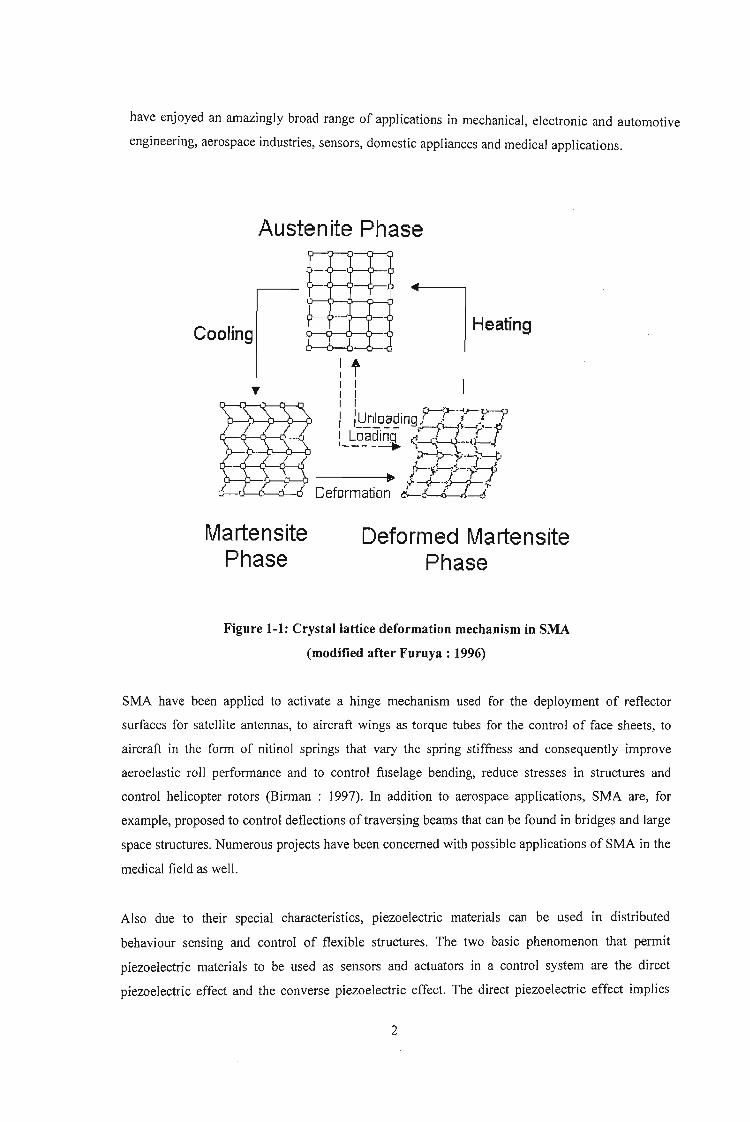
The novel performances of shape memory materials include high damping capacity, large
recoverable strain and recovery stress and property changes due to thermal or stress induced
microstructural transformations. The shape memory effect of SMA is based on the crystal lattice
deformation mechanism shown schematically in Figure 1-1 (Furuya : 1996).
Thus, austenite can be transformed into martensite by the application of temperature or stress or
both and vice versa, thereby allowing control of the material's physical properties. SMA are also,
commercially, easily fabricated into the useful forms of fibres, wires, ribbons, particles and thin
films to be used with polymer (and more recently metal) matrices to form smart composites that
have enjoyed an amazingly broad range of applications in mechanical, electronic and automotive
engineering, aerospace industries, sensors, domestic appliances and medical applications.
Austenite Phase
[HeatingCooling
:t: I II I
I, :u.. nIOading,rr}-~ilr!r--- - - ;rr--/>---> '-;,-'-
I Loadinq (.f~J' ..I.-L-.1_- - ------., "\ -Lt r.-
r5.-.•.m·.··'.,.... /. ----.. ~Y''''''J~,fJ-J~-.j.-.. :-p
~ J+J~ADeformation d.-r..LLf~'r-
MartensitePhase
Deform ed MartensitePhase
Figure 1-1: Crystal lattice deformation mechanism in SMA
(modified after Furuya : 1996)
SMA have been applied to activate a hinge mechanism used for the deployment of reflector
surfaces for satellite antennas, to aircraft wings as torque tubes for the control· of face sheets, to
aircraft in the form of nitinol springs that vary the spring stiffness and consequently improve
aeroelastic roll performance and to control fuselage bending, reduce stresses in structures and
control helicopter rotors (Birman : 1997). In addition to aerospace applications, SMA are, for
example, proposed to control deflections of traversing beams that can be found in bridges and large
space structures. Numerous projects have been concerned with possible applications of SMA in the
medical field as well.
Also due to their special characteristics, piezoelectric materials can be used in distributed
behaviour sensing and control of flexible structures. The two basic phenomenon that permit
piezoelectric materials to be used as sensors and actuators in a control system are the direct
piezoelectric effect and the converse piezoelectric effect. The direct piezoelectric effect implies
2
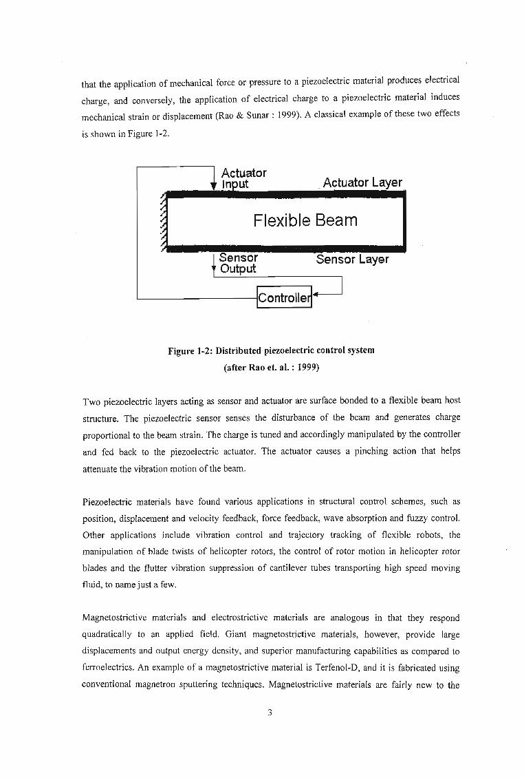
that the application of mechanical force or pressure to a piezoelectric material produces electrical
charge, and conversely, the application of electrical charge to a piezoelectric material induces
mechanical strain or displacement (Rao & Sunar : 1999). A classical example of these two effects
is shown in Figure 1-2.
Actuator.Actuator Layer, Input
/.~ Flexible Beam~~/.
Sensor Sensor Layer~ Output
IlControlle~
Figure 1-2: Distributed piezoelectric control system
(after Rao et. al. : 1999)
Two piezoelectric layers acting as sensor and actuator are surface bonded to a flexible beam host
structure. The piezoelectric sensor senses the disturbance of the beam and generates charge
proportional to the beam strain. The charge is tuned and accordingly manipulated by the controller
and fed back to the piezoelectric actuator. The actuator causes a pinching action that helps
attenuate the vibration motion of the beam.
Piezoelectric materials have found various applications in structural control schemes, such as
position, displacement and velocity feedback, force feedback, wave absorption and fuzzy control.
Other applications include vibration control and trajectory tracking of flexible robots, the
manipulation of blade twists of helicopter rotors, the control of rotor motion in helicopter rotor
blades and the flutter vibration suppression of cantilever tubes transporting high speed moving
fluid, to name just a few.
Magnetostrictive materials and electrostrictive materials are analogous in that they respond
quadratically to an applied field. Giant magnetostrictive materials, however, provide large
displacements and output energy density, and superior manufacturing capabilities as compared to
ferroelectrics. An example of a magnetostrictive material is Terfenol-D, and it is fabricated using
conventional magnetron sputtering techniques. Magnetostrictive materials are fairly new to the

smart materials domain and its application has been limited by poor fracture toughness, eddy
current losses at higher frequencies and bias and prestress requirements. These materials are
currently being investigated in hybrid SMA composites to induce martensitic transformation of the
SMA by the application of a magnetic field.
1.2 Summary of Related Studies
The review of impact damage resistance and low velocity impact presented by Miyazaki,
Sandstrom and Wei (1998) is used as a basis for this summary as it incorporates most of the
relevant and important conclusions pertinent to this investigation.
The high strain energy absorption capacity of SMA, evident from Figure 1-3, has been used by, Li,
Liang and Rogers (1991) to extend material lifespan by accelerating closure of fatigue cracks and
lowering crack propagation speed.
As an extension to the application proposed by Li et. al. (1991), Du and Nie (Miyazaki et. al. :
1998) showed that stress concentrations at notch tips can be reduced by placing prestrained Ti-Ni
wires on the surface of tensile test specimens and causing them to contract with shape memory
through the application of electric heating. Recent attempts have been made by Paine and Rogers
and colleagues (Chaudhry, Kiesling, Paine and Rogers : 1996; Ellis, Jia, Lalande and Rogers :
1997; Paine and Rogers : 1994a; Paine and Rogers : 1994b) to improve the impact damage
resistance of brittle thermoset matrix composites by hybridising with SMAs. The response of
various SMA hybrid composites with different interaction configurations to low velocity impact
was examined.
4

800 HS 38-750 Graphite
2015
5056 Aluminium
10
Strain (%)
5
Superelaslicnilinol
F533/s-glass
oo
100
200
700S2-Glass
600
..-...
.(j)
500Q.c")
0....---(/)(/) 400IDL..
+-'(j)
AIS14142, as-quenched
300
Figure 1-3: Stress-strain curves for various engineering materials
(modified after Miyazaki et. al. : 1998)
To facilitate observation of the failure modes and to simplify fabrication, Ti-Ni fibre/epoxy
composite materials were laminated to host composites as surface layers instead of being
embedded. Graphite/bismaleimide (gr/bis) and glass/epoxy were used as the two host composites.
An aluminium epoxy composite and Kevlar epoxy composite were also used as comparison hybrid
layers. The dissipated impact energy and deflection during impact were determined from force
time data through low velocity impact tests conducted using an instrumented drop weight impact
5
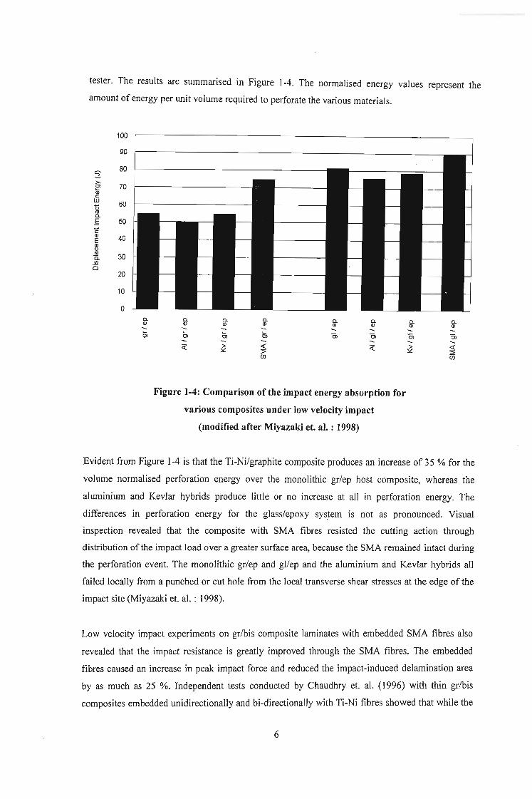
tester. The results are summarised in Figure 1-4. The normalised energy values represent the
amount of energy per unit volume required to perforate the various materials.
100
90
80s:>0-
70~Q)cill 60t>roa.E 50CQ)
40EQ)0ro
30a.f/)
(520
10
0a. a. a. a. a. a. a. a.Q) Q) Q) Q) Q) Q) Q) Q)- - - - - - -0, L L 0, Cl Cl Cl ClCl Cl- - - -<i" ~ <! <i" ~ <!
~ ~(f) (f)
Figure 1-4: Comparison ofthe impact energy absorption for
various composites under low velocity impact
(modified after Miyazaki et. al. : 1998)
Evident from Figure 1-4 is that the Ti-Ni/graphite composite produces an increase of 35 % for the
volume normalised perforation energy over the monolithic gr/ep host composite, whereas the
aluminium and Kevlar hybrids produce little or no increase at all in perforation energy. The
differences in perforation energy for the glass/epoxy system is not as pronounced. Visual
inspection revealed that the composite with SMA fibres resisted the cutting action through
distribution of the impact load over a greater surface area, because the SMA remained intact during
the perforation event. The monolithic gr/ep and gl/ep and the aluminium and Kevlar hybrids all
failed locally from a punched or cut hole from the local transverse shear stresses at the edge of the
impact site (Miyazaki et. al. : 1998).
Low velocity impact experiments on gr/bis composite laminates with embedded SMA fibres also
revealed that the impact resistance is greatly improved through the SMA fibres. The embedded
fibres caused an increase in peak impact force and reduced the impact-induced delamination area
by as much as 25 %. Independent tests conducted by Chaudhry et. al. (1996) with thin gr/bis
composites embedded unidirectionally and bi-directionaIIy with Ti-Ni fibres showed that while the
6

stiffness and ultimate strength of the composite remained unchanged, an increase in absorbed
impact energy of 41 % was observed in the bi-directional SMA hybrids and 23 % in the
unidirectional SMA hybrids. The bi-directional hybrids, however, suffered from a 22 % larger
delamination area as compared to plain gr/ep composites. Contact deformation, global bending
deformation and transverse shear deformation were identified as the energy absorption
mechanisms for the SMA/graphite/epoxy composites under low velocity impact. At very low
velocities, contact energy absorption is the most effective mechanism, while the shear deformation
absorbs most of the impact energy at higher impact velocities. The total energy absorption of the
SMA hybrid composites increases when the stress-induced martensitic transformation occurs.
Birman, Chandrashekhara and Sain (l996a; 1996b) studied the effect of low velocity impact on
global deformations of composite plates and show that global deflections of composite plates can
be reduced by a factor of two or more by using SMA fibres embedded within the composite
material. It is also shown that SMA fibres are more effective when they are orientated along the
shorter edges of rectangular plates.
Finally, by coupling Ti-Ni SMA to PZT via a TiOz buffer layer, the final composite material can
sense and actuate to dampen structural vibration without the use of external control as depicted in
Figure 1-5 (Miyazaki et. al. : 1998).
StressWave
........ + + + +'; T T T T
"'-"'-''--'" + + + + «K:}{}-<D-{)....... + + + +/O'-O{)-I::: + ++++++~tR::Sb;:{}l
.::::+ +... ++++~tR:::RJ~
+ .,. ....~ {~jJ~~. + + + +........ + + + +/H.}-{)-.{J :::::: + + + +....... \J '-.n :-: -:.: + + + + + ++ + .t-Q-Qi)-iJhCI
/r\...nJ""U::':-:-:-:-:<. ++ ++ + +++ 1-Q-~r{J-{JhCI
/1-<""-' '-<":-:-:':-:-:-:->:+ ++++ ++ + 'f{j--b-t:H:R:1:::.",. ',',', + + + +.. ':..... +++++ ++ + JO-Q-Q-{:x!
+ + + +
~Ti-Ni
~ PZT
1::::::::1 Ti02
I::::1 Buffer
Figure 1-5: Self sensing and actuation of a SMA PZT smart material
(after Miyazaki et. aI. : 1998)
The stress wave propagates through the' Ti-Ni SMA producing a stress induced martensitic
transformation where some of the mechanical energy is converted into heat. The wave further
produces a voltage across the first ferroelectric layer that can be used to produce an out-of-phase
7
stress wave by the second ferroelectric layer, and in turn attenuate the stress wave. A mechanical
metallic impedance buffer (such as aluminium, titanium or Ti-Ni) is used to provide time for the
counter-stress attenuation to occur.
This brings to a close a very brief summary of relevant work in the area of impact load attenuation
and smart composites. A more detailed review follows in Chapter 2.
1.3 Objectives and Overview
Smart materials have enormous potential in a wide variety of industries,· not only in aerospace,
biomechanics and civil engineering, as highlighted earlier. However, due to a lack of
understanding, these materials are still considered hi-tech and too sophisticated to be used in
ordinary day-to-day design applications. Thus, in a broader context, the aim of this thesis is to
increase the understanding of the behaviour of smart materials, and in so doing help to erase the
perception that these materials are beyond the reach of the vast majority of designers and
engineers.
To this end, the focus of this investigation is on the ability of smart materials, specifically SMA,
magnetostrictive materials and piezoelectric materials, to enhance the performance of an ordinary
metal-matrix composite beam in terms of load carrying capability and energy absorption capacity
(The understanding behind this concept is that a SMA must be a better energy absorber than
traditional materials because of their larger strain to failure characteristic). This is the primary
objective of the investigation and includes a study on the effect of magnetostrictive inclusions on
the energy absorption capacity of the SMA.
The second important aspect of the objectives of this investigation is the increase in understanding
and competence for the author in peripheral activities such as numerical modelling and simulation
techniques, data interpretation and evaluation, as well as a broader understanding of material
behaviour in general.
Thus, the outputs of the study can be summarised as follows:
• The investigation of a magnetostrictive SMA hybrid composite with piezoelectric actuator,
smart material that is capable of enhancing load. attenuation and energy absorption
characteristics.
8

• Fundamental understanding of the microstructural behaviour of SMA, magnetostrictive
materials, piezoelectric materials and smart composites in general.
• Fundamental understanding and competence development in numerical modelling and
simulation techniques, data interpretation and evaluation.
The investigation towards the design of an impact resistant smart composite includes a detailed
literature review and analytical and numerical modelling.
The literature review encompasses general impact loading, the micromechanic behaviour of shape
memory alloys, magnetostrictive materials and piezoelectric thin films. The output of this phase is
the familiarisation of all relevant work conducted in the said fields, as well as a thorough
understanding of the behaviour of the various material types. A competence is thus established to
facilitate the theoretical modelling of the individual materials under various environmental stimuli.
With the competence in individual material modelling developed, the next phase combines this
knowledge into a single analytical model characterising the smart composite under investigation.
This is achieved in a step-wise procedure, beginning with a standard SMA composite model, then
introducing the magnetostrictive inclusions activated by an external magnetic field and then finally
attaching a piezoelectric actuator to the model in the attempt to generate the required magnetic
field, under impact, to stimulate the magnetostrictive inclusions to cause martensitic transformation
in the SMA. Attention is given to the energy absorption characteristics of the designed smart
composite.
The theoretical modelling is executed together with numerical modelling using an appropriate
software package. Thus, the scope of this investigation also includes the thorough understanding of
numerical analysis in general as well as the specific software. The numerical modelling tool is used
at each step in the analytical modelling procedure as a qualitative verification of results and to
develop competence and proficiency in various modelling techniques used in the set-up and
execution of the final model.
1.4 Methodology
The methodology employed in this investigation is driven by two primary factors. The first is the
unique approach that the author puts forward to attempt to simplify the characterisation of damage
in not just metal matrix composites but in materials in general. The second factor is the lack of
9

available literature on smart material energy absorption as well as a lack of precise theory for short
fibre composites.
The characterisation of the energy absorption of a structural system is relatively simple in the
elastic region of the materials involved. This is as a result of well-defined, predictable material
behaviour and mature analytical models. However, once one enters the realm of plasticity, the
characterisation gets very complex due to complex theories surrounding various damage models.
Having a practical engineering background, the author finds these complex analytical descriptions
extremely frustrating and limiting to practical engineering predictions. Thus, in an attempt to
facilitate simple engineering models, the concept of an 'instantaneous' modulus is introduced. This
instantaneous modulus, which from now on will be referred to as the damage modulus ED, is to the
plastic region what Young's Modulus, is to the elastic region of a materials physical
characterisation. The distinct difference is that unlike Young's modulus, the damage modulus is
not a slope (differential) but a physical factor describing the stress behaviour of a material through
its strain range i.e.
and
O'=Ec for 0 ::s; c ::s; plasticity strain
for all strain
The importance of the damage modulus is two fold. Firstly, it is a single factor that describes a
material through its entire strain range. Thus, it easily accommodates materials with a defined
plasticity point, such as steel, as well as materials without a defined plasticity point such as
aluminium, for example. The second contribution that the damage modulus makes is that it takes
into account 'damage' in material modelling and thus simplifies analyses by a considerable
amount. To substantiate this new concept, the damages modulus will be used in this investigation.
As a starting point, ED is derived from the stress-strain curve for the various materials involved,
i.e. aluminium (AC8A alloy), aluminium oxide (AI20 3) and NitinoI. It should be noted that in the
elastic region ED = E. The simplification is that now Elastic theory can be used in the in the plastic
strain range as well. Further, damage is taken into account by incorporating and effectively
reducing Young's Modulus in the plastic zone.
The second factor driving the methodology of this investigation is the lack of available literature
on energy absorption of smart metal matrix composites. This is particularly important, as every
proposed model needs some kind of basis to reflect its applicability and serve as a measure of
10

accuracy. The route using experimental investigation as a tool to provide this basis is,
unfortunately, not viable as South Africa views the use of smart materials, especially SMA such as
nitinol, as military orientated and special clearances are required to import these materials. Thus,
the only remaining option is to use published experimental results of other authors as a means of
verifying this particular analytical model and, after a detailed literature investigation (as
summarised in the previous chapter), the article by Aggag, Han, Nam and Takahashi is found to be
most pertinent to the objectives of the current investigation.
In this investigation the author develops an analytical model, based on the damage modulus
concept, to predict the behaviour of a short fibre metal matrix composite during a Charpy impact
test. The model is verified using the experimental results given by Aggag et aI. A smart composite
Charpy test is then simulated by replacing the instantaneous modulus characteristics of some of the
fibres with the damage modulus of a SMA. The results obtained are then compared to those
obtained by Aggag et al to quantify the effect of the SMA on impact energy absorption. To
accommodate the lack of precise theory describing the characteristics of short fibre systems, the
analytical model is based on continuous unidirectional fibre reinforced composite theory adapted
by a strength factor and geometric factor to make it more representative of a short fibre system.
The former reduces the strength of the system, while the latter reduces the stiffness of the system.
Once these two factors are set during the verification phase of the investigation, they remain
unchanged through the remainder of the analyses, as they are only affected by geometry. The onset
of failure of a system is initiated when either the system strain reaches the failure strain of the
fibres or when the system stress reaches the strength of the composite. Once failure is initiated, the
stress in the system is kept constant until the load that the system can support goes to zero. Also
simulating failure is the decreasing depth of the system. This is modelled simplistically as a linear
function from the original depth to the final depth of the system. The final depth is obtained by
determining the minimum cross-sectional area required to support the failure load.
Finally, to simulate the effect of the magnetostrictive inclusions, the SMA model is subject to
varying degrees of pre-strain to represent the reaction of the magnetostrictive elements to varying
degrees of magnetic field. Numerical simulation is accomplished using the Matlab software
package.
To refresh the reader's memory, a brief excerpt of the Charpy impact test is given.
The Charpy impact test was developed prior to the development of fracture mechanics and was
used as a means of measurement of the fracture toughness parameters that are required to perform
a structural integrity assessment during the design process. The test continues to be used today as
11

an economical quality control method to assess the notch sensitivity and impact toughness of
.engineering materials. While it is usually used to test the toughness of metals, similar tests can be
used for polymers, ceramics and'composites.
The Charpy impact test measures the energy absorbed by the high strain rate fracture of a standard
notched specimen. The specimen is broken by the impact of a heavy pendulum hammer, falling
through a fixed distance to strike the specimen at a fixed velocity (constant kinetic energy). Tough
materials absorb a lot of energy when fractured, and brittle materials absorb very little energy.
Figure 1-6 gives a graphical representation ofthe Charpy impact test.
The impact energy measured by the Charpy test is the work done to fracture the specimen. On
impact, the specimen deforms elastically until yielding takes place (plastic deformation), and a
plastic zone develops at the notch. As the test specimen continues to be deformed by the impact,
the plastic zone work hardens. This increases the stress and strain in the plastic zone until the
specimen fractures. The Charpy impact energy therefore includes the elastic strain energy, the
plastic work done during yielding and the work done to create the fracture surface. The elastic
energy is usually not a significant fraction of the total energy, which is dominated by the plastic
work. The total impact energy depends on the size of the test specimen, and a standard specimen
size is used to allow comparison between different materials.
12

Figure 1-6: Graphical representation of the Charpy impact test
13

CHAPTER 2
2 LITERATURE REVIEW
The objective of a literature review is to familiarise oneself with relevant up to date information so
that the investigation does not repeat previous work and is expedited by the knowledge and
understanding consequently gained. The author has identified four review areas for the current
study and includes impact loading, shape memory alloys, magnetostrictive materials and
piezoelectric materials. It is practically impossible to peruse all the available literature in a realistic
time period and as a result the number of articles sourced and reviewed has been limited to the
most relevant in each area. A summary of the information and understanding gained is presented
below. A selected bibliography, together with the initial review that was conducted, is presented in
Appendix A.
2.1 Impact Loading
Composite materials are finding increasing use in engineering applications, because of their high
specific strength, where the ability to withstand impact loading is an important design criterion.
The application of composites to such dynamically loaded structures requires knowledge and
understanding of the response of the composites to high strain rates. Numerous studies on the
mechanical behaviour of composite materials under impact loading have been conducted.
However, while the author has sourced an abundance of such articles dealing with polymeric
matrix composites, there seems to be a lack of investigations into the impact behaviour of metal
matrix composites. One such article that deals solely with polymeric matrix composites is by
Harding and Ruiz (1998) where an elastic stress analysis using average elastic constants for the
composite in the principle directions of reinforcement is used as a basis for initial estimates of the
maximum stress reached for the specific loading conditions. While this approach forms a good
starting point, it needs to be used with caution as the values of the various elastic constants may
vary with the rate of loading; a point also alluded to by Harding et. al. (1998). Also, it is important
to estimate the critical stress levels below which the composite deforms elastically and above
which catastrophic failure occurs. To accomplish this task the use of data from small specimen
tests is proposed. Small-scale structural tests should follow, in which loads and deflections on
plates or beams, for example, as well as the damage can be monitored. This data is then used to
develop and ! or validate methods of modelling of the composite in general. (It is important to
design tests and generate results that are not too restrictive in their application. This point is further
examined later in the review.)
14

Thus, Harding et. al. (1998) give the overriding requirement, when designing a test specimen for
determining material properties, that the values of the properties measured should be independent
of the specimen dimensions and geometry. While standard specimen designs are available for
homogenous isotropic ductile metallic materials, these are not applicable for material properties at
impact rates of strain, in general. The most versatile technique available for such application is
based on the split Hopkinson pressure bar (SHPB). The constraints on this approach are that the
length of the test section must be sufficiently short for force equilibrium to be established across
the specimen early in the test and that the interface between the specimen and the loading bars
must not introduce extraneous stress waves that interfere with the standard wave analysis. The
limitation of this approach, as applicable to composite materials, is that the specimen dimensions
need to be large in relation to the scale of reinforcement if the measured properties are to be
characteristic of the material. This directly conflicts with the SHPB requirement of a small gauge
length. A further limitation is that the process of damage initiation and propagation in composite
materials is more sensitive to the specimen geometry than the corresponding deformation process
in ductile metallic materials. Typical small specimen tests include through the thickness shear tests,
compression tests, tension tests (in-plane tension test and through the thickness tension test) and
interlaminar shear tests (single and double lap shear test).
Harding et. al. (1998) further describes two types of small-scale structural tests, viz. the plate test
and the beam test (Figure 2-1). In both cases, an instrumented bar is accelerated by a projectile to
the required velocity before it comes into contact with the specimen.
C====Fi=rs=t=l=m=p=a=c=t=~=====:::"",,,::::r::::=~:r====s=p=e~c~~m::Ie=n=~
r- 30__V --"__~_I__ln_p_u_t_B_a_r_____J~
Projectile
Figure 2-1: Schematic of small-scale structural test
(modified after Harding et. at. : 1998)
15

The initial gap between the bar and the specimen is made sufficiently large so that the bar is
unstressed when it subsequently impacts the centre of the specimen but not so large that the bar
velocity has decayed to any significant extent. The advantage of the beam test over the plate test is
that high-speed photography may be employed to study the progressive accumulation of damage.
Beam tests with high-speed photography showed the stages in the process of failure as follows.
I. Initiation of fibre fracture at the rear surface.
2. Crack extension into the beam across several 0° and 90° laminate layers.
3. Blunting of the crack by delamination, allowing the delaminated plies to unload.
4. As bending deflection continues to increase, the crack propagates a little further and the
process repeats itself.
An important observation is that delamination plays a more significant part in the process for
longer beam specimens while cracking predominates in short beam specimens and only becomes
significant in longer specimens in the later stages when the remaining uncracked thickness is quite
small.
The experimental portion of the investigation by Harding and Ruiz (Harding et. aI. : 1998)
considered the problem of a transverse impact of a simply supported laminated beam. The model is
broken up into two phases, viz. a) initiation of failure and b) extension of damage. Failure is
assumed to be initiated when the tensile strain in the outermost fibres reaches a critical value. In
this first stage the velocity of the input bar is approximately constant. This initial loading is treated
as quasi-static and conventional beam theory is used to determine the time to fracture initiation. In
the second phase two processes combine to extend the initial damage. The crack is extended by
fibre fracture of fibres aligned along the beam or matrix cracking along fibres aligned across the
beam. This process is governed by the same equations as the first phase, but with the appropriate
reduced values of the effective beam depth and stiffness taken into account. The second process of
the second phase is delamination. Delamination causes portions of the beam to be unstressed and
thus, a new beam geometry is defined to take this into account. The central deflection of the new
geometry beam is obtained using elementary beam theory and in turn used to determine the strain
energy. The release of strain energy due to delamination is also determined. The extent of
delamination is dependent on the energy release rate. Figure 2-2 shows an excerpt of the
experimental results obtained by Harding et. al. (1998).
16

Long a.am T..t5LBn (S-700m/a)
-4k~:::';':+-:-:±~+-:;:':;':~+~~!+~~~~::;:,;:,:,\
+tttt:~:::::H:: :ttt;:: :tt~:t:I::~t~:+I+ttt:~ ~~
nM(o)
Figure 2-2: Test record for a beam specimen that failed under transverse impact
(after Harding et. al. : 1998)
While deflections and forces are in good agreement with experimental results, this method under
estimates the extent of damage and it is the opinion of the author that this is as a result of
redefining specimen properties based on new effective beam depth and stiffness only, Le. the
model does not appear to take into account the reduced crack or delamination propagation energy
as compared to initiation energy. Further, for a crack to propagate through the beam all fibres
aligned across the beam should experience delamination to varying degrees up to the crack tip. The
Harding and Ruiz model (Harding et. al. : 1998) only predicted delamination of two layers out of a
twenty-one layer beam and eight layers out of a forty-one layer beam. The basing of delamination
on energy release rate also contributes to ineffective predictions because of the wide range of
variance in most composite materials.
Numerical modelling of the transversely impacted simply supported beam is accomplished using
the DYNA-3D finite element code that uses the Chang and Chang criterion of failure of
composites.
Hamouda and Hashmi (1998) expand on the issue of testing of composite materials at high rates of
strain by citing their important considerations to the design of experiments for dynamic testing of
17

composite materials, viz. a) devising launch mechanisms to produce the desired stress state, b)
fixing specimens in the test assembly, c) selection of specimen geometry, d) test duration and
equilibrium time, e) the complexity of composite failure mechanisms, f) measuring transient
parameters accurately and g) data collection, management and interpretation. Hamouda and
Hashmi (Hamouda et. al. : 1998) proceed to present a useful table (Table 2-1 below) categorising
various experimental techniques for high strain rate testing and thereafter discuss eight such
techniques including Charpy-Izod, drop weight, expanding ring, SHPB,compression SHPB,
tension SHPB, shear and plate impact tests.
Review of the above mentioned discussion yields important considerations that the author feels
need to be borne in mind when designing an experimental investigation. Results of the Charpy
Izod tests are dependant on the specimen dimensions and hence cannot be used to obtain
fundamental data on the impact response of a composite material.
The drop weight tests are used to determine the compressive stress-strain behaviour of materials at
medium strain rates of the order of 10.2 S·l and greater. Investigation of e-glass fibre reinforced
epoxy indicates a dynamic failure stress 25 % greater in magnitude than the corresponding static
value. Also, drop weight testing of chopped strand mat reinforced polyester shows that increasing
the angle of impact (angle of inclination) results in a decrease in the corresponding damage area
and a reduction in the depth of surface indentation, for any given incident kinetic energy.
The expanding ring test is difficult to perform and requires very precise displacement measurement
and is hence limited in its use. One of the advantages, however, is the ability to test extremely high
. strain rates (of the order of 500 S·l). Tests conducted on graphite-epoxy rings show that for a matrix
controlled failure (90° fibre orientation) the material properties exhibit higher elastic modulus and
strength than the static values. In both cases (0° and 90° fibre orientation) the static ultimate strain
was three times higher than the dynamic value.
18

Table 2-1 : Experimental techniques for high strain rate testing
(after Hamouda et. al. : 1998)
Applicable Strain Testing TechniquesMode
Rate (S-I)
Compression <0.1 Conventional testing machine
0.1 - 100 Servo-hydraulic machine
0.1 - 500 Cam plastometer and drop test
200 - 104 Hopkinson pressure bar
104 _ 105 Direct impact using air gun
apparatus
Tension < 0.1 Conventional testing machine
0.1 - 100 Servo-hydraulic machine
100 - 104 Hopkinson pressure bar in tension
104 Expanding ring
> 10' Flyer plate
Shear <0.1 Conventional testing machine
0.1 - 100 Servo-hydraulic machine
10 - 103 Torsional impact
100 - 104 Hopkinson pressure bar in torsion
103.:... 104 Double notch shear and punch
104_ 107 Pressure-shear plate impact
As previously discussed, the major complication of the SHPB test is the antagonistic requirements
of the test procedure and material constraints. Also, load transfer between the loading bars and the
specimen has to be carefully designed to avoid stress wave reflections due to an impedance
mismatch. Compression SHPB tests conducted on short cylindrical specimens of woven glass
epoxy laminates show an increase in the ultimate compressive strength under impact loading that
appeared unaffected by specimen geometry (Hamouda et. al. : 1998). Hamouda and Hashmi also
modified the standard SHPB test to be applicable to tensile tests, though the results are not very
accurate. To increase accuracy it is recommended that a set of strain gauges be attached directly to
the specimen. Recently a new electrical resistance technique for detecting failure in balanced
angle-ply carbon fibre reinforced plastics has been developed that uses the variation of electrical
resistance of tubes during expansion when subjected to internal explosive loading pUlses.
19
Unfortunately, all the shear property determination techniques described are based on the SHPB
and none can be used with confidence due to the difficulty in inducing pure uniform shear in the
specimen.
In general, plate impact experiments provide the most versatile technique for material property
evaluation and provide the highest strain rates available today. A full description of the experiment
is referred to by Hamouda and Hashrni (Hamouda et. al. : 1998).
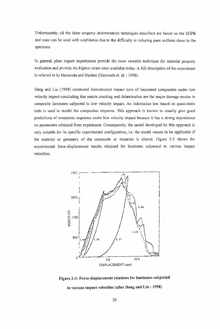
Dang and Liu (1998) conducted instrumented impact tests of laminated composites under low
velocity impact concluding that matrix cracking and delamination are the major damage modes in
composite laminates subjected to low velocity impact. An indentation law based on quasi-static
tests is used to model the composites response. This approach is known to usually give good
predictions of composite responses under low velocity impact because it has a strong dependence
on parameters obtained from experiment. Consequently, the model developed by this approach is
only suitable for its specific experimental configuration, i.e. the model ceases to be applicable if
the material or geometry of the composite or impactor is altered. Figure 2-3 shows the
experimental force-displacement results obtained for laminates subjected to various impact
velocities.
356:) It~irL
2670
"..,
~ \1Pt
tq~'~i 't.~ \ 3.40
1 "II .\ i1\ I
/ \j ~J ~ iI .:\ '",
" it \
I 4•• 9 \I
"'I\\\
\ .\ I.
"5.0 10.0
D£SPLACEI,,'lENT (mm)
Figure 2-3: Force-displacement relations for laminates subjected
to various impact velocities (after Dang and Liu : 1998)
20

The results of the testing and simulation show that as the laminate thickness increases the stiffness
and strength increases causing a subsequent increase in peak contact force and decrease of contact
duration, maximum deflection and energy absorption. Fibre angle does not play a significant role
in impact response. The contact duration and peak contact force decreases once penetration takes
place while the maximum deflection remains relatively constant as the impact velocity increases.
Increase in impact velocity does not affect energy absorption, though there is a significant jump in
energy absorption due to penetration.
According to Dharani and Flocker (1998), while standard finite element wave propagation codes
are useful for easy determination of stresses caused by impact loading, it is difficult to model the
important interlayer delamination process. Thus, their paper presents a method that allows
traditional wave propagation codes to model this interlayer debonding of laminated architectural
glass subjected to low velocity impact. While the application presented in the paper is specific to
architectural glass, the author believes it contains inherent generic conclusions that will assist in
this investigation. One such conclusion is that limited debonding results in a more compliant
structure that can absorb more energy. Further, when glass is impacted by a spherical projectile, the
cone crack is of primary concern and the stress of concern is the maximum principle stress on the
inner surfaces directly beneath the impact site. A typical cone crack with cone angle f/J formed in a
brittle material after an impact from a spherical projectile is shown in Figure 2-4a while
Figure 2-4b illustrates a cone crack formed in the outside layer of a laminated architectural glass
unit. This is significant because if a ceramic piezoelectric material is used on the surface of the
smart material in the current investigation, the formation of a cone crack can interrupt the
piezoelectric effect and nullify the intended results.
R Outside Layer
Depth
1~__-----'"
(a)
Interlayer
(b)
Inside layer
Figure 2-4: Cone crack in an infinite half-space and a laminated glass unit
(after Dharani et. a!. : 1998)
21

A propagating cone crack is modelled in a finite element mesh by setting deviatoric stresses and
hydrostatic tension to zero at the appropriate time and location. Thus, a cracked element will not
support shear or tension but will support compression. The interface debonding model is based on
the primary assumption that debonding is a propagating phenomenon that starts and then
progresses away from the point where a crack meets an interface layer. Analysis of interface
debonding (mechanics of peel adhesion) show that at high peel angles tensile forces dominate at
the point of debonding, while at low peel angles shear forces dominate (Dharani et. al. : 1998).
Similar to cracking, debonding is modelled by relaxing the element stresses by setting deviators
and hydrostatic tension to zero. Again, the debonded region cannot support shear or tension but can
support compression. It is assumed that the tensile and shear forces required to cause debonding
are related, i.e. less shear is required to debond a strip of adhesive from a substrate if a tensile force
exists between the two. The relationship between these stresses is obtained through peel tests as
illustrated in Figure 2-5.
A strip of adhesive with a flexible backing is applied to a rigid substrate. A peel force P is applied
to the flexible backing at peel angle lU. The force required to strip the adhesive from the backing is
then measured. This is repeated for various peel angles.
p
,Cl)
Flexible BackingAdhesive
2h- \------~----------__:7a
Rigid Substrate
Figure 2-5: Illustration of the plane strain peel test
(after Dharani et. al. : 1998)
22

If the tensile and shear stresses at the debonding interface are denoted by 0"0 and To respectively,
then
(J0 = 2fJP(fJme + sin 0) )
"0 = aPcosO)
Where the terms a, fJ and me are given by
(3Y ) y.
fJ = 8Eah3
(G )~
a = 2Eah
(4Eh3(1- cos 0) )) ~ h
m = - cOSO)e 3P
Where G and Yare the shear and Young's moduli respectively for the adhesive, E is the Young's
modulus of the backing, a is the adhesive thickness and 2h is the flexible backing thickness.
If a linear relation exists between the tensile and shear debonding stresses then,
;::: (2YPgo)~(Jellt a
and
(G )~
"ellt ;::: P" 2Eah
Where O"eut denotes the debonding tensile stress when no shear is present and "ellt denotes the
debonding shear stress when no tensile stress exists. P90 is the debonding force at 90° peel angle
and Po is the debonding force at very Iow peel angle.
For the finite element code Dharani et. al. (1998) uses a non-reflecting boundary for the clamped
sides of the specimen to simulate an infinite body. This is achieved by producing an impedance
matching function that cancels incoming stress waves so that none are reflected back from the
boundary.
23

The main energy absorption mechanism for normal composite materials is fragmentation. Matrix
failures can occur by tension and compression and fibres failure by tension. Belingardi, Gugliotta
and Vadori (1998) compares the results obtained by applying a computational methodology, based
on the finite element technique, with experimental results of composite material plates subjected to
impact loading. The DYNA-3D finite element code is used for the numerical modelling. A
composite material comprising a stack of laminae of unidirectionally reinforced matrices IS
considered along with the assumption that the material behaves linearly until, under certain load,
brittle fracture occurs. Due to the brittle behaviour of such composites, the mechanism of energy
dissipation is fracture, i.e. fragmentation of material, fibre breakage and / or matrix breakage. A
polynomial expression for the definition of the critical material surface in the stress space is
adopted as all the coefficients are easily determined from pure tension or pure shear tests, as
opposed to a piecewise continuous surface model to take into account different modes of failure.
The model also incorporates the ply-discount approach for failure where some of the load carrying
capabilities of the single lamina are lost when fibres or matrix break down. This means that the
load carrying capability of the stack of laminae is globally reduced and when all the laminae are
broken the material is completely degraded to no mechanical characteristics.
The Young's moduli and Poisson's ratio are obtained from laboratory tests and then used to derive
the Lame constants 2, a], /3}, f-l and f-l}. These constants are used to calculate the Cauchy stress
components from the following equation:
~l A+ 2a l + p, + 2J1 + 4J11 A+ a l A+ a l a a a Ell
1;2 A+ a l A+ 2Jl A a a a E22
1;3 A+a 1 A A+ 2Jl a a a E33
= a a 2(Jl + JlI) a a E I2~2 aT23
0 0 a 0 2Jl 0 E23
1;1 0 a a a a 2(Jl +JlI) E31
Where Tij are the Cauchy stress components and Eij are the Euler-Almansi strain components.
A plane stress state is assumed resulting in T23 , T3J , T33 , E23 and E3J reducing to zero. Thus, the
constitutive law for a single lamina with a single set of unidirectional fibres is defined. The
polynomial expression for the critical surface is modified to a piecewise continuous surface in the
stress space with failure occurring when one of the stress components satisfies the following
conditions:
24

Fibre mode - Tension
Fibre mode - Compression
(~r" JMatrix mode - Cracking
Matrix mode - Crushing
where X" Xe, Y" Ye are respectively the tension and compression strength along and perpendicular
to the fibre direction while Se is the shear strength of a single lamina in the 1-2 plane. f3 is a factor
that reduces the too high sensitivity of the fibre breakage collapse mode to the shear effect and 7:
takes into account the nonlinear effect of the shear stress on the failure surface.
A critical remark made by Belingardi et. al. (1998) is that in tension along the fibre direction, when
some mechanical characteristics of a lamina are degraded, dependency between strain and stress
ceases to exist; the stress law is imposed in the time domain regardless of the strain state. When the
critical surfaces are reached and fibre breakage occurs, the stress state is
and must hold for every strain state.
For determination of the energy dissipation during the damage phase of the material a co-rotational
formulation is used.
where (d~nt ) is the stored internal energy in an undamaged material, Dj, are theundamaged ,
components of the velocity strain and Cijrs are the components of the fourth order constitutive
tensor.
25

When the material is subjected to degradation, the stored internal energy is,
Thus, the energy dissipation during the damage phase of the material is
(dW;nt) (dW;nt) f ( * )---;jf - ---;jf = Dij Cijr.l - Cijr.l Er",do.undamaged damaged n
Belingardi et. al. (1998) proceed to present a good case study that has the ability to be used to test
an initial model generated for the current investigation, in a general sense.
The issue of impact energy absorption of polymer composite sandwich beams is investigated using
a beam in three point bending with roller supports by Mines (1998). The beam was constructed
using woven glass, aramid and carbon polyester resin skins with Coremat or foam cores by
applying the wet layup technique. Coremat is a proprietary material that consists of a non-woven
polyester felt with 50 % micro-spheres. The core is impregnated with resin during the wet layup
lamination process resulting in a solid material with isolated pores. Mines (1998) defines the
structural behaviour of sandwich structures under impact response to include matrix damage, fibre
pullout and failure, delamination and core multiaxial crushing. In the case of the three point bend
beam, there are eight possible modes of structural failure depending on material and structural
configuration. These failure modes include upper skin compression failure, core shear failure,
lower skin tensile failure and upper skin wrinkling. The best mode of failure for energy absorption
is upper skin failure and subsequent stable core crushing. The upper skin failure is modelled using
standard linear elastic theory and the compression failure stress of the upper skin and the core
crushing failure is modelled using a limit analysis assuming global beam deformation in the central
plastic hinge. The energy absorption is taken to be the area under the force-displacement graph.
The basic modelling process can be summarised as follows. The upper skin failure is determined
using the compression failure stress. The upper skin is then neglected from further computations
and stable crushing ofthe core is assumed. For a given core upper surface strain the position of the
neutral axis is calculated using force equilibrium conditions across the central beam section. The
beam force and moment distribution is then derived. The force is fed into an empirical multiaxial
core crush criterion as a shear stress and the neutral axis is recalculated. The compression stresses
due to contact load are neglected due to the high crush strength of the Coremat core. The new
26

neutral axis gives a revised moment and force that is used to predict the beam deflection for the
given core upper surface strain.
Static loading analysis showed good correlation between experiment and theoretical results post
upper skin failure. No results of the upper skin failure (theoretical) using compression failure load
is given to compare with the experimental results, and impact loading analysis is restricted to low
velocity, dropped object problems where the impact resistance of a material is determined largely
by its strain rate properties. Force-time results are obtained from accelerometer readings and then
the displacement of the impact mass is determined from its acceleration.
The results obtained by Mines (1998) reveal that for the short span beam, the upper skin dynamic
failure load is larger than the static load failure as well as that theoretically predicted. The
theoretical core crush model (elastic-plastic model with central hinge) also under predicts the
experimental forces by approximately 50 %. Further, the theoretical strain-rate dependent model
shows little difference to the theoretical strain-rate independent model. For the larger span beam
tests the upper skin dynamic failure load is less than that of the static loading conditions. The
dynamics of these tests, however, are different as the beam bounces away from the impactor.
Comparing these results to those obtained by Harding et. al. (1998) for laminated composites, the
obvious difference lies in the damage initiation and propagation in the composite. While the fibre
reinforced composite failure initiated in the bottom of the beam and propagated upward, the failure
in the sandwich panels is initiated in the upper skin of the beam. The fibre reinforced polymer
composite also experienced higher loads and lower displacements than the sandwich panel, though
this can be attributed to the lower strength and higher ductility respectively, of the core material of
the sandwich structure.
The remainder of the investigation (Mines : 1998) briefly discusses quality of beam manufacture,
variation of hinge size with beam span, multiaxial crush criteria for core materials, effects of
moving the position of the impact, of using clamped boundary conditions and having beam in
plane loads, effect of low density core materials, effects of geometry and velocity of impactor,
other modes of beam failure, beam specific energy absorption and effects of skin reinforcement
orientation and type of resin.
The investigation by Charles, Collembet, Jeronimidis, Lalbin and Lataillade (1997) presents a
methodology for numerically taking into account the physics of damage events during impact of
composite structures. They propose that numerical calculations must be combined with
experimental data to account for the three dimensional, multiscaled and coupled characteristics of
damage phenomena. Charles et. al. (1997) analysed the impact of circular long fibre glass-epoxy
27

0°/90° symmetrical laminated plates using a hemispherical impactor of mass 2.3 kg and velocities
less than 6 m/so Only local damage events are observed in transverse matrix cracking and
delamination.
Numerically, the time step is linked to the smallest dimension of the mesh to yield a condition of
stability in time integration. An averaging technique developed on the scale of a finite element is
used to model matrix cracking, i.e. the effect of cracks in the matrix is quantified by calculating
elastic characteristics of a homogenised undamaged material equivalent to the initial material
containing cracks. Maximum stress criteria are used to initiate numerical cracking and its effects.
An extension criterion is added to take into account the stress concentration at the tip of the cracks.
Delamination is modelled by assembling the different layers of the structure with double nodes.
When the link force (force at the double nodes) in a specific direction exceeds a critical value,
separation of the double nodes is effected. This is essentially a contact technique based on
Lagrange multipliers and differs from the classical fracture mechanics energy based approach.
Collembet, Lalbin and Lataillade (1997) give the conditions for the separation of a double node. At
a given interface a double node is numerically authorised to separate if, for the lower layer all
adjacent finite elements are cracked and, for the upper layer one adjacent finite element is cracked
or one adjacent double node is already separated, as indicated in the example of Figure 2-6.
For the numerical model to be an adequate representation of real life events, physical
considerations based on experimental observations need to be integrated with the numerical
condition. Thus, a damage chronology based on experimental observations has to be postulated
together with critical initiating factors. Crack extension is numerically modelled as equivalent to
the creation of a new crack in an element adjacent to a cracked one with the critical extension
stress lower in the element receiving the crack than the critical initiation stress in the element
originating the crack. The contact projectile/target is simplified as a node and the projectile is
represented as a weighted point with initial velocity.
28

Extension of delamination Initiation of delaminalion
Upper Layer
Lower Layer
Extension of delamination authorised
I\;[:~?::)I Cracked Element
CJ Non Cracked Element
Figure 2-6: Two dimensional representation of delamination
conditions between two layers with double nodes
(after Collombet et. al. : (1997)
Expanding the issue of crack growth further, Needleman (1997) describes a framework for
modelling crack growth based on introducing one or more cohesive surfaces into a continuum. In
the traditional approach to fracture mechanics a parameter characterising the crack tip field, e.g. the
energy release rate, is assumed to be a material property and is distinguished from stress analysis.
Thus, incorporating a model of the fracture process into the initiallboundary value problem
formulation provides an alternative approach. Needleman (1997) has chosen for discussion a
framework where the failure characteristics are embedded in a phenomenological constitutive
relation that describes separation along one or more cohesive surfaces. Within the framework, the
continuum is characterised by two constitutive relations; one relates the stress and deformation in
the bulk material and the other relates the tension and displacement jump across a cohesive surface.
A mathematical analysis is presented using volumetric and cohesive surface internal virtual work
with Lagrangian description. The author believes that this is too in-depth modelling for the
purposes of the current investigation and is inclined to combine this methodology with that of
Charles et. al. (1997) for the numerical scenario.
Lewis (1998) presents a methodology for predicting and modelling material failure in solids
subjected to impact loading using classical void growth models in a material point method.
However, the author is of the opinion that this is too in-depth an analysis for the modelling
requirements of the current investigation. Chandra and Rajendran (1998) present a review of
micromechanical and engineering modelling of polymeric matrix composites under high velocity
impact. While high velocity impact is outside the scope of the current investigation this paper
29
describes alternative views to matrix microcracking that the author believes is important. The first
view is that when microcracks form in an undamaged composite, the stresses change with all stress
components becoming non zero, in general, and that microcracking initiates when the stress in the
90° plies becomes equal to the transverse strength of the unidirectional material. The alternative is
that the first microcrack forms when the energy released due to the formation of that microcrack
exceeds some critical value, known as the microcracking toughness of the composite material
system. According to Chandra et. al. (1998), this energy prediction captures most features of
experimental observations and appears to be a significant improvement over strength theories. Also
presented in this paper is a useful figure showing the various energy dissipation mechanisms active
during an impact event and is used as Figure 2-7 in this thesis to bring to an end the review on
impact loading.
30

,
IrrecoverableThermal Energy,Et
Inelastic Matrix andInterface Energy
Bending
Shear Energy, Ebs
Membrane Energy, ~m
Contact Energy, Ec
Matrix Cracking
Fiber Damage
;;..o"j
,/
ENERGY DISSIPATED IN DAMAGE
INELASTIC ENERGY
ELASTIC ENERGY
LOST ENERGY
Kinetic Energy of Impactor
t
t
-------~
Impactor Variables Target Information
mass massmaterials materialsvelocity -fibreshape -matrixsize thicknessangle of incidence stacking sequence
Ply 1
DelaminationPly 2
Ply 3
Ply 4
Interface Debond
Figure 2-7: Schematic of an energy balance approach in an impact event
(after Chandra et. aI. : 1998)
31

2.2 Shape Memory Materials
The novel performances of shape memory materials include high damping capacity, large
recoverable strain and recovery stress and property changes due to thermal or stress induced
microstructural transformations. When the material has been transformed to the martensitic phase,
it can be subjected to significant plastic deformation under relatively modest load since the yield
limit of the material in the martensitic phase is much lower than its counterpart in the austenitic
phase. The martensitic transformation represents a diffusionless lattice transformation involving
shearing deformations (Funakubo : 1987). Martensitic transformations can involve slip and
twinning, but for this transformation to be reversible, deformation by slip should not be involved in
the process (Birman : 1997). The term SIM (stress-induced martensite) identifies martensite
obtained as a result of mechanical loading. The yield stress of SMA varies greatly dependent on
the phase and according to Funakubo (1987) can be an almost linear function of temperature. Table
2-2 illustrates an example of the differences in material properties of the austenitic and martensitic
phases.
Table 2-2: Properties of nitinol Ni-44.8wt % Ti
(after Birman : 1997)
Phase Austenite Martensite
Modulus of elasticity (GPa) 30.0 13.0
Poisson's ratio 0.33 0.33
Coefficient of thermal expansion (10.6f'C) 12.5 18.5
Start temperature (QC) 29 23
Finish temperature Cc) 51 5
Most analytical constitutive models of SMA rely on a linear relationship between martensitic and
austenitic properties with the proportionality coefficient associated with the martensitic fraction,
though this should be used with caution, as it still needs to be experimentally verified. To add
complexity to the model, stress-strain curves within the range MF < T < AF are affected by the
formation of stress-induced martensite causing the martensitic fraction to continuously change as a
result of increasing or decreasing stress. At the same time, the change of the martensitic fraction is
accompanied by changes in the properties of the material. When T > AF the material is in the
32

stress-free state and the martensite formed as a result of increasing stress represents a superelastic
behaviour (Birman : 1997).
Although the first attempts to mathematically describe the behaviour of shape memory materials
are traced back to the 1970s (Birman : 1997), only the more recent contributions are reviewed in
this thesis. The Tanaka model (Nagaki and Tanaka : 1982) was originally developed to describe a
three dimensional solid but its practical implementation was limited to the one dimensional case.
The model has since been described in a number of papers (Tanaka : 1986; Tanaka : 1990; Tanaka
: 1991) and is based on the energy balance equation and the Clausius-Duhem inequality. The
constitutive equations relate the rate of change of the second Piola-Kirchoff tensor of stresses to
those of the Green's strain tensor, temperature and the set of scalar variables, which characterises
the extent of a phase transition. In the case of martensitic transformations the scalar variables are
reduced to just one parameter, Le. the martensitic fraction. The coefficients in the tensor
constitutive equation are the tensors of elastic and thermoelastic moduli and the material
(transformation) tensor that, in general, depends on strain, temperature and martensitic fraction.
The elements of the tensors of elastic and thermoelastic moduli are considered linear functions of
the martensitic fraction with the other state variables being expressed as a function of the rate of
change of martensitic fraction. For the one dimensional model the elastic and thermoelastic moduli
are assumed constant. Also, the martensitic fraction in the process of martensitic and reverse
transformations is expressed in terms of exponential functions oftemperature and stress.
The Liang and Rogers (1990) one dimensional model is derived by modifying the Tanaka model
by replacing the finite form exponential transformation kinetics equation with a cosine law. The
three dimensional model (Liang and Rogers : 1991) is developed based on the first and second
laws of thermodynamics and the concept of the Helmholtz free energy. The theory utilises
experimental results that illustrate that the phase transformations are governed by the distortional
energy. Thus, the general state variables are defined in terms of just three parameters, viz. the
equivalent strain, absolute temperature and martensitic fraction.
The Brinson one dimensional model (Brinson : 1993; Brinson and Lammering : 1993) utilises the
rate constitutive equation of Tanaka as well as elements of the Liang and Rogers model. Brinson
introduces the sub-division of the martensitic fraction into two components corresponding to the
temperature induced and stress induced martensites. Two constitutive relations are considered. The
first is based on the assumption that material parameters remain constant and results in a law
similar to that in the Tanaka and Liang and Rogers models. The second relation is based on
isothermal stress-strain curves and yields the conclusion that only the thermoelastic term associated
with the stress-induced martensite has to be retained in the constitutive equation. This form of
constitutive equation is obtained without the assumption of constant material parameters, i.e. the
elastic modulus is assumed to be a linear function of the martensitic fraction, the material constant
is proportional to the elastic modulus corresponding to the current value of martensitic fraction and
the thermoelastic modulus is assumed constant.
The three dimensional model of Boyd and Lagoudas (Birman : 1997) is a modification of the
constitutive theories of Liang and Rogers and Tanaka, i.e. the constant material tensor assumption
during the transformation process is removed, and the elastic and thermoelastic tensors are
calculated in terms of the martensitic fraction according to the rule of mixtures.
The model of Abeyaratne, Knowles and Kim (Birman : 1997) is applicable to one dimensional
thermoelastic solids with a tri-linear stress-strain curve. For each temperature, this curve consists
of three straight sections corresponding to an initial increase of the stress as the strain increases
from zero, a decline to a local minimum and a subsequent increase. Accordingly, even though the
stress in a thermoelastic bar remains constant, the strain may be a piecewise function of the local
temperature. This one dimensional model accounts for thermo-mechanical coupling and satisfies
the Clausius-Clapeyron inequality.
Attempts to incorporate shape memory actuators in composite structures to improve their impact
tolerance have been conducted by Paine and Rogers (I 994a; 1994b) and Birman et. al. (l996a;
1996b) and have already been discussed in Chapter I.
In terms of micromechanics modelling of smart composites, Taya (1999) discusses a summary of
analytical modelling as applied to piezoelectric composites, shape memory alloy fibre composites
and piezoresistive composites and presents models that take into account coupled behaviour
between stress, electric field and magnetic field. Table 2-3 summarises various types of coupled
behaviour between mechanical, thermal and electromagnetic phenomena. The first five rows
denote linear coupling behaviour while the last four are for nonlinear or non-colinear coupling
behaviour.
34

Table 2-3: Coupling behaviour
(after Taya : 1999)
Coupled Behaviour Flux Vector/Field Vector Field Vector or Scalar Coupling Coefficient
Piezoelectric Stress Electric field e
Thermoelastic Strain Temperature change a
Pyroelectric Electric displacement Temperature change p
Piezomagnetic Stress Magnetic field a
Magnetoelectric Electric displacement Magnetic field x
Magnetostrictive Strain Magnetisation Nonlinear
Electrostrictive Strain Electric field Nonlinear
Piezoresistivity Electric current density Electric field s (nonlinear in strain)
Shape-memory effect Stress, Strain Temperature change Nonlinear
The constitutive equation for materials with linear coupling behaviour include the flux vector f,
field vector Z and thermal coupling vector if , in the form of,
where E is the coupling coefficient and ethe temperature scalar.
The flux, field and thermal coupling vectors can be expanded to the form,
T S A,
(6xl) (6xl) (6xl)
L=D
z= -E p:rr=
(3xl) (3xl) (3xl)Jj -H 0
(3xl) (3xl) (3xl)
where r,D and B are the flux vectors of stress, electric displacement and magnetic flux
respectively; S, E and H are the field vectors of strain, electric field and magnetic field
respectively; and A, and P are the thermal stress vector, and pyroelectric vector respectively.
35

The constitutive equation is then inverted to yield
where F is the compliance property tensor and A the compliance thermal vector.
Thus, E. If =] and E. A + if = O.
Consider an arbitrary composite that contains numerous fillers made of smart material with linear
coupling behaviour. The composite is subjected to an applied field vector on the boundary, 20
,
where the temperature is assumed constant (Figure 2-8a).
~-+--E .m
Em
zo
t t t
~ ~ ~(b)
Figure 2-8 : Linear coupled composite with smart material fillers
(after Taya : 1999)
If the volume average of the flux and field vectors in each phase are used to define the flux and
field of the composite, then
where v is the volume fraction and the subscripts c, m andjrefer to the composite, matrix and fibre
respectively.
36

Applying the constitutive equation results in (constant temperature)
where i = c, m and!
The averaged field vector in the composite, Zc' is equal to the applied field since the disturbance
field, 2, vanishes after integration over the entire composite, i.e.
Thus,
where A is the constraint tensor relating the average field in the filler domain to the applied field,
i.e.
Zf =AZ =AZc 0
A is obtained using Eshelby's model which is given by (Taya: 1999)
where f and 2 are the disturbance of flux and field vectors owing to the existence of fillers and
Z' is the equivalent inclusion eigenfield vector replacing the filler (Figure 2-8b).
The uniform flux and field vectors are related by
The disturbance field vector Z is linearly related to the eigenfield vector Z' by the Eshelby
tensor, S , for the coupling problem.
2 = 8.2'
37

The Eshelby tensor is a function of the constituent properties and shape of an ellipsoid inclusion
since the components of the flux and field vectors of the filler then become uniform. An average
Eshelby tensor for non-ellipsoid fillers is defined by Taya (1999).
In terms of nonlinear coupling, Eshelby's model can be used to adequately determine the
macroscopic stresses in a composite with SMA fibres. The compressive stress in the matrix at a
temperature above the austenite finish temperature, Afi can be computed using Eshelby's model for
elasto-plastic deformation (Taya : 1999).
The stress in the fibre is given by
where C is the stiffness tensor, e is the strain disturbance, eT is the transformation strain, ep is
the plastic strain and e* is the eigenstrain which has a non-zero value in the fibre domain and
vanishes in the matrix.
The various strains are given by
where u is the Poisson's ratio, CT is the prestrain given to the fibre at room temperature, ep is the
plastic strain of the fibre axis and S is Eshelby's tensor.
The above three equations are used to solve for e* as
where the superscript' -1' denotes the inverse of a matrix.
The plastic strain in the fibre, ep
' is obtained by satisfying the yield condition for the fibre,
38

((jf),3 - ((jf)1 J = eryf
where ayf is the yield stress of the fibre and the numerical subscripts denote the general fibre
directions.
Taya (1999) also presents a useful model on piezoresistive materials, but this is left for discussion
in the review on piezoelectric materials.
An alternative model is given by Sittner, Takakura, Tokuda and Ye (1998) where a two
dimensional mechanical model of polycrystalline SMA based on crystal plasticity and the
deformation mechanism of SMA, is described in an attempt to calculate the deformation
behaviours of SMA under multiaxial loading conditions. According to Sittner et. al. (1998), the
majority of models proposed to describe the thermo-mechanical behaviours of SMA are based on
thermodynamics and kinetics whereas all of the SMA in practical applications are polycrystal.
Every grain in the polycrystalline medium has its own orientation with twenty-four potential
variants determined by the crystallographic structure of the material. The stress is a symmetric
second rank tensor whose number of independent variables is six, though the temperature is a
scalar parameter (single variable). According to the loading conditions (magnitude and direction)
only in such potential variants that are in the preferred directions in the grains of the polycrystal
will the transformation be induced. The relation between stress, ,and the transformation strain Yr
in the process of stress induced martensite transformation and its reverse transformation is shown
in Figure 2-9. T is the experimental temperature and 'MS m, 'MJ{T) , 'ASm and 'Ap(T) are the
martensite transformation starting and finishing stresses (critical stress) and the austenite
transformation starting and finishing stresses (critical stress) under temperature T respectively.
rTmax is the maximum transformation strain determined by the materials crystaIIographic structure.
39
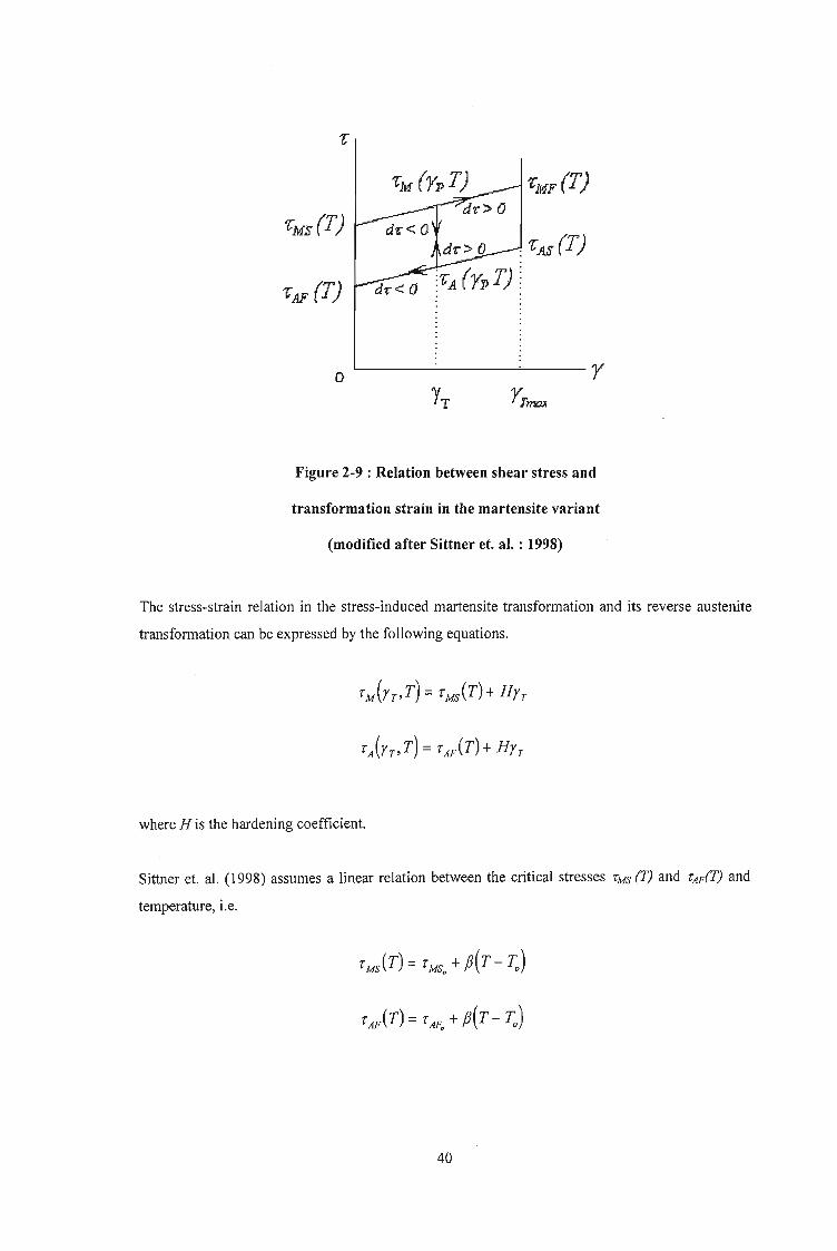
'fn (T)
1:MF (T)
o'---------'----r
Figure 2-9 : Relation between shear stress and
transformation strain in the martensite variant
(modified after Sittner et. at. : 1998)
The stress-strain relation in the stress-induced martensite transformation and its reverse austenite
transformation can be expressed by the following equations.
where H is the hardening coefficient.
Sittner et. al. (1998) assumes a linear relation between the critical stresses 'MS (T) and 'AF(T) and
temperature, i.e.
rMAT) = rMSo +,B(T-1;,)
rAAT) = rAFo + ,B(T- 1;,)
40

where f3 is the temperature coefficient and rMS. and rAF. are the transformation critical stresses
under reference temperature To.
Thus, all the critical stresses can be obtained by the following expressions,
Taking the differential of the constitutive equation yields
drM(YT,T) = MT+HdYT
drA(YT,T) = MT + HdYT
where dr is the increment in shear stress, dT is the increment in temperature and drT is the
increment in transformation strain.
Thus, in the loading (d r > 0) and unloading (d r < 0) process under constant temperature (dT = 0),
dr>O and r<rM(ypT):drr =0
dr > 0 and r =rM(rr,T) and YT < YTmax :dYT =~
dr> 0 and YT =YTmax :dYT =0
dr < 0 and r> rA(ypT):dYT = 0
dr < 0 and r = rAYpT) and YT > 0 :dYT = drH
dr < 0 and YT = 0 :dYT = 0
In the temperature cycles under a constant stress (dr = 0),
41
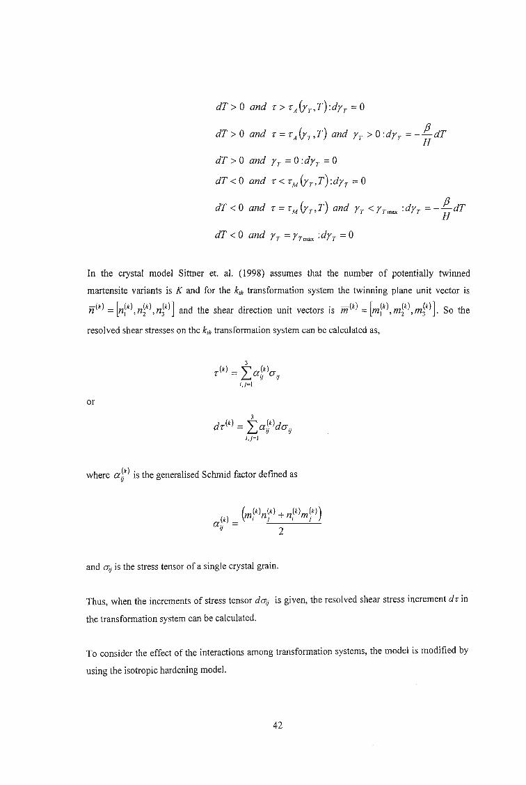
dT> 0 and, > ,AYpT) :dYr =0
dT> 0 and, = ,Ah,T) and Yr > 0 :dYr = -'!!"dTH
dT > 0 and Yr = 0 :dyr = 0
dT < 0 and, < 'M (YpT) :dh =0
dT < 0 and, = 'M (yr,T) and h < Yrmax :dh =- ; dT
dT < 0 and Yr =Yrmax :dYr =0
In the crystal model Sittner et. al. (1998) assumes that the number of potentially twinned
martensite variants is K and for the kth transformation system the twinning plane unit vector is
n(k) = [n(k) n(k) n(k)] and the shear direction unit vectors is m (k) = [m(k) m(k) m(k)] So the1 ' 2 , 3 I , 2 ' 3 •
resolved shear stresses on the kth transformation system can be calculated as,
or
where at) is the generalised Schmid factor defined as
and aij is the stress tensor of a single crystal grain.
Thus, when the increments of stress tensor daij is given, the resolved shear stress increment dr in
the transformation system can be calculated.
To consider the effect of the interactions among transformation systems, the model is modified by
using the isotropic hardening model.
42

ork
drt)~~),T)= fJdT +HLdy~)i=1
andk
r~k)~y),T)= rAAT) + HIyY)i=1
or
k
dr~k)~~),T)= fJdT +HLdy~)i=1
Also, the transformation is assumed to finish when the sum of volume fractions of the variants in
the crystal is equal to unity, which manipulates by Sittner et. al. (1998) to,
Y(I) + y(2) +... + y(k) +... + y(K) < YT T T T - Tmax
Once dr ~k) is calculated in this process, the transformation strain increment d£T;j of crystal grain
component can be calculated as,
K
dBTij
= L a~k)dr~k)k=1
and then the total strain increment in the crystal is calculated as,
where d£e is the elastic strain increment calculated by Hooke's law in the crystal."
For the polycrystalline model, the interaction among grains are incorporated by using the stress
constant idea (Sittner et. al. : 1998), i.e. the stress of the grain is the same as the macroscopic stress
in the material and the macroscopic strain is the average of the strains of every grain.
The calculation process is schematically represented in the flowchart of Figure 2-10.
43

Closely related to the strain of a material is its Poisson's ratio. By strict definition, the Poisson's
ratio of a material is only valid for small strain linear elastic behaviour and thus, it becomes
necessary to define a strain varying Poisson's ratio for highly nonlinear elastic materials such as
biomaterials and smart materials. Evans, Smith and Wootton (1999) discuss the importance of the
use of a Poisson's function in appropriate circumstances.
The usual strain quoted is the engineering strain, e (sometimes called the nominal or Cauchy
strain), which is a measure of extension to initial length, la.
where I; is the current length of the specimen.
MacroscopicStress: given
oE Stress Constantr------ -------------,II,,
Hooke's Law-t:--~
Macroscopic Strain
Figure 2-10 : Flowchart of strain calculation process
(modified after Sittner et. a!. : 1998)
When dealing with larger extensions, it is common to refer to the true strain or Hencky strain. Most
textbooks state in words that the true strain is the ratio of extension to instantaneous length, that is
(0/)/1;, but then go on to define true strain as a summation of these (Evans et. al. : 1999),
44

,; 8/I> = f- =In(l + e)log /
In ;
Thus, the true strain is sometimes referred to as the log true strain Clog' The disadvantage is that this
integral returns a secant value of the extension and not a localised tangent value. Thus, if the
deformation is nonlinear this true strain may not accurately reflect instantaneous conditions, but
more those relative to starting conditions. The simple ratio between extension and instantaneous
length does return a tangent value of the deformation and is referred to as instantaneous true strain.
Cin! can be calculated with sequential experimental data as,
for I; -1;_1 small enough (Evans et. aI. : 1999).
The summation of Cint is equivalent to Clog if the step size between data points is sufficiently small.
The summation of the instantaneous true strains is referred to as the total instantaneous true strain
Clot ,
In the limit of infinitesimal strains, engineering strain e, log transform true strain Clog and total
instantaneous true strain Clot are identical, and as the value of e increases, the Clog and Clot diverge
from e. The engineering, log transform and total instantaneous true strain are essentially
summations and thus, initial changes in dimension have far greater effects on these summative
strains than later changes. The instantaneous true strain, C;n/ , does not do this. Similar functional
changes in length produce similar changes in Cin! at any overall strain.
45

The standard definition of the Poisson' s ratio is,
where x is the direction of the applied strain andy is the orthogonal direction.
Using either e, Clog or C{o{ strains to calculate Poisson's ratio gives respectively,
and, as with e, Clog and C/o/ strains, if the step size is sufficiently small, they are all equivalent.
The Poisson's function vint is defined as,'Y
-CintV --_Y
int.", - 5.mt.T
If experimental conditions do not allow the rapid collection of dimension data, the Poisson's
function can be calculated using the graphical method or one of the numerical methods described
by Alderson, Alderson and Evans (1997). Evans et. al. (1999) also present their findings on various
methods available for smoothing of experimental data. The author believes that this is useful
information and the reader is referred to the preliminary literature review, presented in Appendix
A, for a summary.
Casciati, Faravelli and Petrini (1998) discuss energy dissipation in SMA, specifically dissipation
by hysteretic plastic cycles in structural bars of significant diameter. Thermal transformations
follow the plasticity process and hence classical mechanical models of constitutive law can be
adopted in the energy dissipation analysis such as the material plasticity law (a simple Von Mises
46

scheme), though an associated hardening rule needs to be selected. Casciati et. al. (1998) uses a
three dimensional Von Mises plastic model with isotropic hardening because it is offered by
commercial finite element codes. The extension of the Mr6z multi-surface hardening model to
SMAs is also given consideration. The model further incorporates the commonly used concept of
back-stress tensor for plastic hardening that provides the centre of the yield surface and varies with
isotropic hardening. The back stress depends on the maximum prestress and the asymptotic value
of the yield stress depends on the strain amplitude. In terms of the modelling process, two key
items are identified viz. the sequence of the transformation temperatures; the differential scanning
calorimeter (DSC) test estimates the temperature of phase transition, and the degree of
heterogeneity of the material which is mainly due to its production technique; plasma technology
offers good homogeneity while standard production processes give rise to finite levels of
heterogeneity.
Once all the discussed variables are taken into account in the model, the energy dissipation appears
to be obtained from the conventional load-displacement method.
47

2.3 Magnetostrictive Materials
An ideal smart material will develop large strokes under precise and rapid control. Piezoelectric
and magnetostrictive materials exhibit rapid responses but have small strokes while SMA have
large strokes, but their control is slow due to thermomechanical control.
The constitutive equations for magnetostriction in the one-dimensional case are,
e=Sa+dH
and
B=da+/-tH
Where e is the strain, B the flux density, S the compliance, athe stress, d the magnetomechanical
cross coupling coefficient, H the magnetic field intensity and /-t the permeability at the nominal
operating stress.
For three-dimensional analysis, these equations transform to,
where
ExCYx
Ey CYyE_
. CY z
[E] = and [0] =Y y: T yz
Yx: T xz
Yxy T xy
S is the 6 X 6 compliance matrix and the magnetostrictive tensor M is,
48
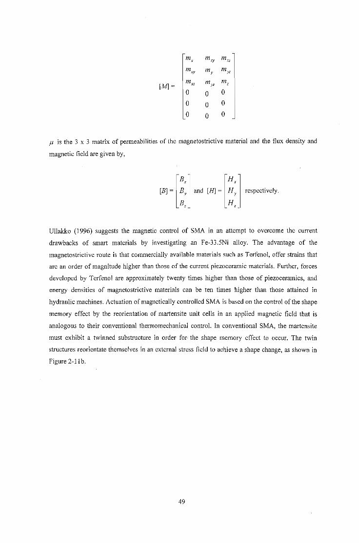
m x m xy m xz
m xy my m yz
[M] =m xz m yz
m z
0 0 0
0 0 0
0 0 0
f.l is the 3 x 3 matrix of permeabilities of the magnetostrictive material and the flux density and
magnetic field are given by,
Ullakko (1996) suggests the magnetic control of SMA in an attempt to overcome the current
drawbacks of smart materials by investigating an Fe-33.5Ni alloy. The advantage of the
magnetostrictive route is that commercially available materials such as Terfenol, offer strains that
are an order of magnitude higher than those of the current piezoceramic materials. Further, forces
developed by Terfenol are approximately twenty times higher than those of piezoceramics, and
energy densities of magnetostrictive materials can be ten times higher than those attained in
hydraulic machines. Actuation of magnetically controlled SMA is based on the control of the shape
memory effect by the reorientation of martensite unit cells in an applied magnetic field that is
analogous to their conventional thermomechanical control. In conventional SMA, the martensite
must exhibit a twinned substructure in order for the shape memory effect to occur. The twin
structures reorientate themselves in an external stress field to achieve a shape change, as shown in
Figure 2-11 b.
49

1---1.----i-J
tiVi ! tHI I
'f---': --t- - :: I
I '
'- '
(a)
\ \\.----4
\ \
/\Unit cells of \
different twinvariants
(b)
1:-.-\ New twin boundary
)---....;------
Cc)
Figure 2-11: Shape changes that cause the strokes in (a) magnetostrictive,
(b) shape memory and (c) magnetically driven SMA
(after Ullakko : 1996)
When stress is applied, some twin variants grow and some shrink to accommodate the shape
change resulting in the eventual establishment of only one twin variant orientated to the applied
stress. The principle of magnetically controlled shape memory materials, called magneto shape
memory (MSM) alloys, is analogous to this method of conventional shape change. The essential
difference is that the motion of the twin boundaries or the interfaces between martensite and
austenite in MSM materials is driven by an applied magnetic field instead of a stress field.
In crystalline ferromagnetic materials, magnetisation vectors lie along definite crystallographic
axes called directions of easy magnetisation and the energy that directs the magnetisation along
these directions is called crystal anisotropy energy. On the application of an external magnetic field
the magnetisation tends to turn away from the easy direction of the unit cell and align in the
direction of the external field (Figure 2-11 a). A high anisotropy energy requires a high external
magnetic field to realign the magnetisation direction.
If the energy of motion of twin boundaries is low enough at the same time, magnetisation can turn
the unit cells as it turns to the direction of the external field to keep magnetisation in the original
easy direction as depicted in Figure 2-11 c. As a result, twins in favourable orientation to the
magnetic field grow at the expense of other twins causing the twin boundary motion and shape
change of the material. The condition that makes possible the turning of the unit cells of one twin
variant into another is expressed as,
50
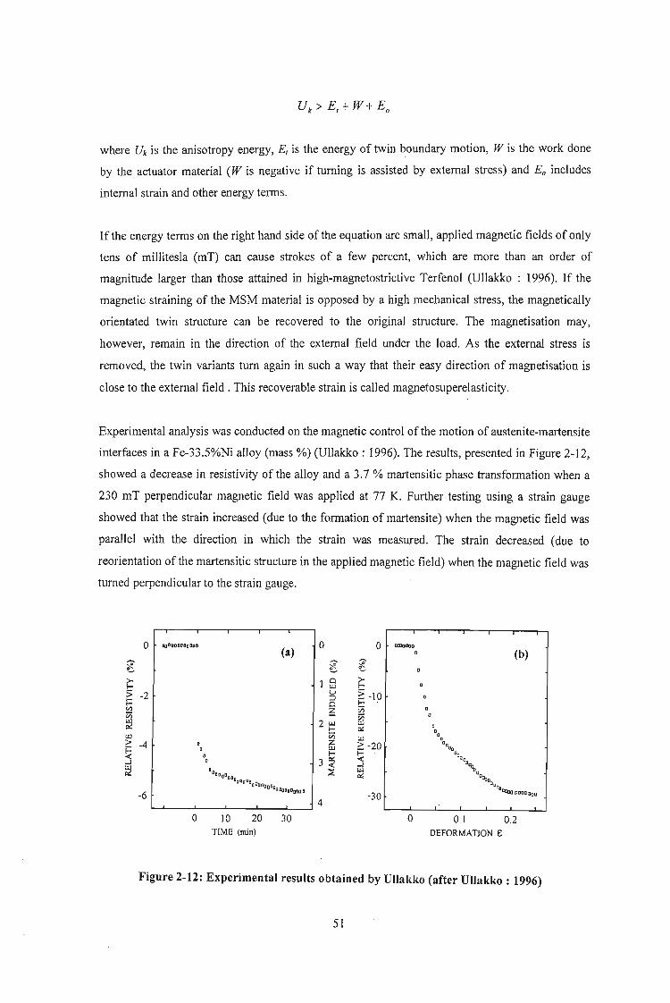
where Uk is the anisotropy energy, Et is the energy of twin boundary motion, W is the work done
by the actuator material (W is negative if turning is assisted by external stress) and Eo includes
internal strain and other energy terms.
If the energy terms on the right hand side of the equation are small, applied magnetic fields of only
tens of millitesla (mT) can cause strokes of a few percent, which are more than an order of
magnitude larger than those attained in high-magnetostrictive Terfenol (Ullakko : 1996). If the
magnetic straining of the MSM material is opposed by a high mechanical stress, the magnetically
orientated twin structure can be recovered to the original structure. The magnetisation may,
however, remain in the direction of the external field under the load. As the external stress is
removed, the twin variants turn again in such a way that their easy direction of magnetisation is
close to the external field. This recoverable strain is called magnetosuperelasticity.
Experimental analysis was conducted on the magnetic control of the motion of austenite-martensite
interfaces in a Fe-33.5%Ni alloy (mass %) (Ullakko : 1996). The results, presented in Figure 2-12,
showed a decrease in resistivity of the alloy and a 3.7 % martensitic phase transformation when a
230 mT perpendicular magnetic field was applied at 77 K. Further testing using a strain gauge
showed that the strain increased (due to the formation of martensite) when the magnetic field was
parallel with the direction in which the strain was measured. The strain decreased (due to
reorientation of the martensitic structure in the applied magnetic field) when the magnetic field was
turned perpendicular to the strain gauge.
0 aoDODDDDoDOD
(a)0 0 Ol1lOQ]D
0 (b)~
~
~ ~ ~~ ~ ~
~ Cl ~UJ:> -2 u ~ -10,.... ;:)r- 0 I-[/.l
~ Vi 0:;::; Vi 0UJ 2 UJ UJe.:: DI- e.:: DU.l Vi U.l •D> -4 a Z
~ -20 DD""
~, UJa I-
~ "0,0".J,
3 ~~
.J '\.aD ~ UJDDaCOD e.:: O~Q
D:lIlDQ!]DCOOODtla 0,"0
-6aOCDDDO!KI1J
-30 Ol:Qoi:!JODtieD
4
0 10 20 30 D D.l 0.2TIME (min) DEFORMATION E
Figure 2-12: Experimental results obtained by Ullakko (after Ullakko : 1996)
51

Livingston (1982) presents a simple model of magnetomechanical coupling in amorphous metal
ribbons (amorphous metals have superior magnetomechanical properties to crystalline
magnetostrictive materials, in general). The major source of magnetic anisotropy in amorphous
metals are structural anisotropies induced by annealing under a magnetic field (and/or applied
stress) and magnetostrictive anisotropies produced by the interaction between magnetostrictive
strain and applied or residual stress.
An amorphous metal ribbon with a width-wise magnetic easy axis is considered. This can be
accomplished by annealing in a large magnetic field parallel to the ribbon width. The resulting
domain structure with no applied field and no applied stress is shown in Figure 2-13a while
Figl!re 2-l3b shows the rotation of the magnetisation towards the length direction due to the
application of a longitudinal magnetic field H.
t ~ tMS
t/ v: lZ \
(a)
(b)
Figure 2-13 : Domain structure of a transverse annealed amorphous ribbon
under (a) zero magnetic field and (b) longitudinal magnetic field
(after Livingston : 1982)
The contribution of the applied field to the energy density is,
- MsHcosB
where Ms is the domain magnetisation per unit volume.
Finding the angle Bfor minimum energy yields, for the longitudinal component of magnetisation,
HM= MscosB = Ms H
A
52
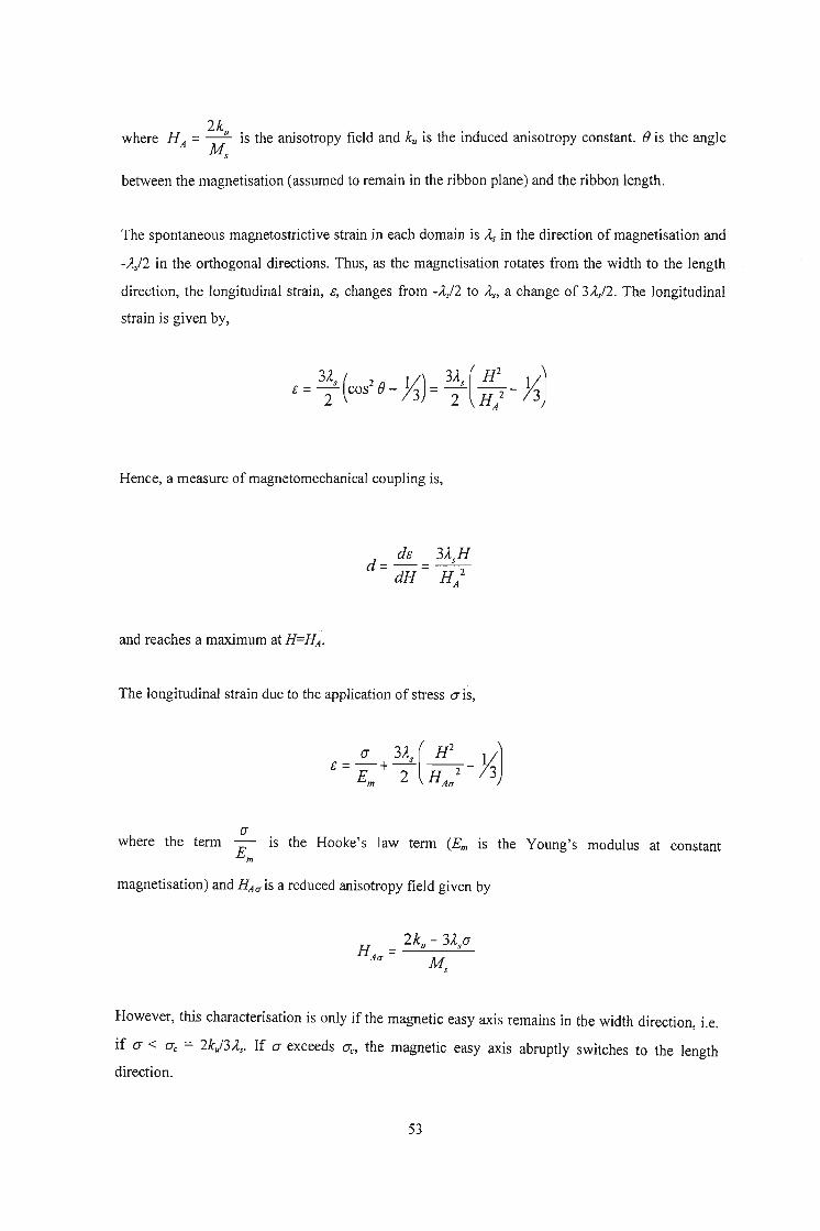
where HA = 2ku is the anisotropy field and ku is the induced anisotropy constant. () is the angleMs
between the magnetisation (assumed to remain in the ribbon plane) and the ribbon length.
The spontaneous magnetostrictive strain in each domain is A.s in the direction of magnetisation and
-A./2 in the orthogonal directions. Thus, as the magnetisation rotates from the width to the length
direction, the longitudinal strain, c, changes from -A./2 to A.s> a change of 3A./2. The longitudinal
strain is given by,
3A.s ( 2 11) 3A.s (H2
1/)e = 2: cos e- 73 = 2: H/ - 73
Hence, a measure of magnetomechanical coupling is,
de 3A.,Hd------ dH- H 2
A
and reaches a maximum at H=HA•
The longitudinal strain due to the application of stress (J is,
awhere the term is the Hooke's law term (Em is the Young's modulus at constant
Em
magnetisation) and HAa is a reduced anisotropy field given by
H = 2ku - 3A.,.aAa M
-,
However, this characterisation is only if the magnetic easy axis remains in the width direction, Le.
if (J < (Jc = 2kj3A.s' If (J exceeds (Jc, the magnetic easy axis abruptly switches to the length
direction.
53

The magnetomechanical coupling factor, k, is related to the fractional energy transfer between
magnetic and mechanical energy and is given by,
The magnetomechanical coupling factor reaches a maximum at H = HAa.
To facilitate rotation of the magnetisation and accompanying magnetostrictive strain, the desired
properties are high As> Ms and Em and low ku, HA and O"c.
Dapino, Flatau and Smith (1998) characterise the resultant strain due to the rotation of magnetic
moments within the material through consideration of the Jiles-Atherton mean field theory for
ferromagnetic hysteresis in combination with a quadratic moment rotation model for
magnetostriction. The internal dynamics of the magnetostrictive rod as it vibrates is modelled
through force balancing that yields a wave equation with magnetostrictive inputs.
A typical current control transducer is considered (Figure 2-14). It consists primarily of a
cylindrical magnetostrictive rod actuator, a wound wire solenoid, an enclosing permanent magnet
and a prestress mechanism.
Wouml Wile Solenoid
..
iPermanent Magnet
Figure 2-14: Cross section of a Terfenol-D magnetostrictive transducer
(after Dapino et. aI. : 1998)
The magnetic moments in the rod have a primary orientation perpendicular to the longitudinal axis.
When current is applied to the solenoid, a magnetic field is produced that causes the moments to
54

rotate to align with the field, and the resulting forces and strains provide the actuator capabilities of
the transducer. The permanent magnets arc used to attain bi-directional strains and forces in the
rod.
The active strain that is generated due to moment rotation and alignment is modelled in two steps.
First an energy based relationship between the current, I, applied to the solenoid and the resulting
magnetisation, M, is derived using a modified Jiles-Atherton field theory for ferromagnetic
hysteresis. A quadratic moment rotation model is then applied to yield the output magnetostriction,
A. The Jiles-Atherton theory is based upon the observation that moments in ferromagnetic
materials, such as Terfenol-D, are highly aligned in domains at temperatures below the Curie point.
The reorientation of these moments within the domains produces anhysteretic magnetisation, Man'
that is completely reversible. However, due to the presence of defects or second phase materials,
such magnetisation curves are rarely observed in commercial materials and the Jiles-Atherton
theory quantifies the observed magnetisation in terms of reversible, Mre", and irreversible, Mim
components.
To quantify the various magnetisation concepts described above, it is first necessary to determine
the effective field, Heffi that acts upon the magnetic moments in the Terfenol rod. Atherton and Jiles
(1986) and Jiles (1991) show that Hefjis dependent on the magnetic field generated by the solenoid,
magnetic moment interactions, crystal and stress anisotropies, temperature and geometry of the
transducer. For this model, the crystalline anisotropies are ignored as they are assumed negligible
under large prestress conditions.
Thus, under the further assumption of fixed temperature and quasi-static operating conditions, Hefj
is modelled by,
where x denotes the longitudinal coordinate, H is the field generated by a solenoid with n turns per
unit length, aM quantifies the field due to magnetic interactions between moments and H(J is the
field due to magnetoelastic domain interactions. The parameter a quantifies the amount of domain
interaction.
A reasonable approximation to the effective field under a variety of operating conditions is given
by,
55

where I is the current to the solenoid, rp(x) is an empirically determined function and a is given
by,
where As is the saturation magnetostriction, Ms is the saturation magnetisation and fia is the free
space permeability.
The approximate Heff expression is limited to low frequencies because ac losses are not
incorporated in the model. The anhysteretic magnetisation is now written in terms of the Langevin
function as,
()[ (
Heff(t, X)] a]Man t, X = M, coth - ()
a Hefl t,x
Nk Twhere the constant a = __B_, kB is Boltzmann's constant, N is the domain density and kBT
/laMs
represents the Boltzmann thermal energy.
The irreversible magnetisation is a partial differential given by,
oM;rr ( ) _ dI ( ) Man(t,x)- M;rr(t,x)(] t,x - d rp x . dMt t k8 - a[ Man(t,x)- M;)t,x)] dM
\P )(&n)where k = 2m/lJl- c) , <p> is the average density of pinning stresses, <En> is the average
density for 1800 walls, c is a reversibility coefficient, m is the magnetic moment of a typical
dH dHdomain and 0 is defined to have the value +1 when dt > 0 and -1 when dt < 0 to guarantee
that pinning always opposes changes in magnetisation.
56

A major disadvantage of this model is that many of the parameters are unknown and have to be
estimated based on average energy requirements for the breakage of pinning sites. The reversible
magnetisation quantifies the degree to which domain walls bulge before attaining the energy
necessary to break the pinning sites, and is given by,
with the total magnetisation deriving to,
dLThe characterisation of the magnetostriction, A == L' in terms of magnetisation, M, remains as
the final aspect of the model. Magnetostriction provides a measure of the active strains generated
by the material because it indicates the relative change in length from the ordered but unaligned
state to the state in which domains are aligned. Consideration of the potential energy of the system
yields,
57

2.4 Piezoelectric Materials
Piezoelectric materials can be used as sensors and actuators in a smart structure because of its
unique electric properties; piezoelectric materials create an electric field when strained, and
conversely, strain under an electric field. As a consequence of this characteristic, researchers have
begun investigating the use of piezoelectric materials to counteract impact loads.
Rao and Sunar (1999) present a survey article that collects recent research studies on sensing and
control of flexible structures via piezoelectric materials. Piezoelectricity basically defines a relation
between an applied electric field and strain, or an applied strain and electric field in certain
crystals, ceramics and films. Piezoelectric materials can be bonded to the surface of host structures
or embedded into laminates. Instead of directly bonding piezoelectric actuators to the surfaces of
host structures, they can also be bonded to host structures by thin viscoelastic layers or they can be
bonded to stiff constraining layers that are in turn bonded to host structures by thin viscoelastic
layers.
In piezoelectric theory, the linear theory deals with small displacement and structural vibrations,
and assumes quasi-static motion indicating that the mechanical and electrical forces are balanced at
any given instant. The non-linear theory deals with the dynamics of anisotropic piezoelectric shells
undergoing large displacements. The linear equations of piezoelectricity in matrix form are written
as
D =ei + PE
for the direct piezoelectric effect, and for the converse piezoelectric effect as
where cl and i denote stress and elastic strain in the material co-ordinates respectively, Q is the
elastic stiffness matrix, e is the piezoelectric stress coefficient matrix, E is the electric field
intensity, D is the electric displacement and P is the dielectric permitivity matrix.
The expanded form of these constitutive equations are given as,
58
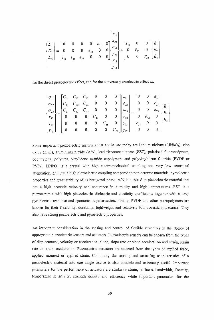
51\
C} [00 0 0
~l5 22
[Po'eSI
D2 = 0 0 0 05 33 + 0e42
D3 el3 0 0Y23 0e23 e33Y13
Y12
o
for the direct piezoelectric effect, and for the converse piezoelectric effect as,
0"11 CII Cl2 CI3 0 0 0 l 51\ 0 0 e13
0"22 C21 C22 C23 0 0 0 5 22 0 0 e23
{~J0"33 C31 Cn C33 0 0 0 5 33 0 0 e33=
"23 0 0 0 C44 0 0 Y23 0 e42 0
"13 0 0 0 0 CSS 0 Y13 eSI 0 0
"\2 0 0 0 0 0 C66 YI2 0 0 0
Some important piezoelectric materials that are in use today are lithium niobate (LiNb03), zinc
oxide (ZnO), aluminium nitride (AlN), lead zirconate titanate (PZT), polarised fluoropolymers,
odd nylons, polyurea, vinylidene cyanide copolymers and polyvinylidene fluoride (PVDF or
PVF2). LiNb03 is a crystal with high electromechanical coupling and very low acoustical
attenuation. ZnO has a high piezoelectric coupling compared to non-ceramic materials, pyroelectric
properties and great stability of its hexagonal phase. AlN is a thin film piezoelectric material that
has a high acoustic velocity and endurance in humidity and high temperatures. PZT is a
piezoceramic with high piezoelectric, dielectric and elasticity coefficients together with a large
pyroelectric response and spontaneous polarisation. Finally, PVDF and other piezopolymers are
known for their flexibility, durability, lightweight and relatively low acoustic impedance. They
also have strong piezoelectric and pyroelectric properties.
An important consideration in the sensing and control of flexible structures is the choice of
appropriate piezoelectric sensors and actuators. Piezoelectric sensors can be chosen from the types
of displacement, velocity or acceleration, slope, slope rate or slope acceleration and strain, strain
rate or strain acceleration. Piezoelectric actuators are selected from the types of applied force,
applied moment or applied strain. Combining the sensing and actuating characteristics of a
piezoelectric material into one single device is also possible and extremely useful. Important
parameters for the performance of actuators are stroke or strain, stiffness, bandwidth, linearity,
temperature sensitivity, strength density and efficiency while important parameters for the
59

performance of piezoelectric sensors include the sensitivity to strain/displacement, spatial
resolution, frequency bandwidth, temperature sensitivity, linearity and hysteresis.
Work conducted by Joshi and Mannas (1993) focuses on smart laminated plates under impact and
the electric field created by piezoelectric patches in the structure. Several studies are made
comparing the electric field generated by piezoelectric patches of varying size, shape and location
within the plate. In terms of patch location, the elastic waves created by the impact take a finite
amount of time to travel between the impact point and the piezoelectric patch. The flexural waves
created by the impact are also dispersive. Thus, the closer the patch is to the impact point the
sooner the electric field is generated and the greater the magnitude of the electric field. The trend in
the effects of patch size to electric field is that as the size of the piezoelectric patch increases, the
average electric field it generates decreases. This is due to the averaging out of positive and
negative oscillating waves of electric field. Larger piezoelectric elements are able to average more
oscillations at the same time and thereby reduce the average electric field generated. The shape of
the piezoelectric patch does not affect the impact force so long as the different shape patches cover
approximately the same area. Patches, however, which are short in the longitudinal direction of the
plate tend to produce higher average electric field values than longer patches that average out
electric field oscillations. A summary of the results obtained by Joshi and Mannas for the effect of
distance from the impact point on electric field generation is presented in Figure 2-15.
200patch distancef ·· 175romnnpact
(mm) 150
125
100
75
50
25
0t..!:.--2-0--4~O--6::":O-~8::":0:----:-1-::::-0-:-0--:1";;2-:::0
time (microsecs)
Figure 2-15: Time between impact and generation of 0.002 V/cm average electric field
(after Joshi and Mannas : 1993)
As a step further, to piezoelectric patches, Agbossou, Mahut and Pastor (1998) investigate the use
of piezoelectric fibre composite elements in structural vibration systems. Similar to normal
composites, there are two kinds of information that characterise the properties of a piezoelectric
60

fibre composite, viz. the internal phase geometry and the physical properties of the phases. Several
micromechanical models of effective electroelastic properties in piezoelectric composites define
Representative Volume Element (RVE) dimensions. The dimension of the RVE is large compared
to typical phase region dimensions and represents the structural homogeneity of the composite
material. For a piezoelectric composite body the homogenous boundary conditions are either,
or
where ulS) and rp(S) denote the displacements and the electric potential on the outside boundary S,
Ef, d' and GO are constant strain, stress and electric potential gradient respectively and U, G, T and
x denote the mechanical displacement, electric potential gradient, stress vector and location vector
respectively.
The effective electroelastic properties are defined by considering the volume average of the
piezoelectric field variables (cij, (jij, rp;) and the relations,
and
where the symbol <> denotes the volume average, (jij, cij and Cijkl are the components of stress,
strain and elasticity tensors respectively, D;, G;, Eij and e;kl are the components of electric
displacement, electric potential gradient, dielectric and piezoelectric tensors respectively.
Using the previous concept of homogeneity, Wang (1992) used a Green's function technique to
develop a solution for an ellipsoid inclusion in a piezoelectric medium while Schulgasser (1992)
demonstrated that five universal relationships, which are independent of geometry at given volume
fractions, connect six of the effective physical constants. In 1995, Yu developed the Periodic
61

Microstructural Model to estimate the electro-thermo-elastic response of piezoelectric composites.
This model used Fourier series to include the constituent properties and shapes, and provided
analytical 'estimates for some effective electro-thermo-elastic moduli of two-phase piezoelectric
composites.
Figure 2-16 displays the method used by Agbossou et. al. (1998) for dynamic analyses of a
piezoelectric fibre composite in an active beam using homogenisation and finite elements.
Elastic and piezoelastic propertiesof the PFC elements
Fixed fibre volume fraction V f
PMH computation: determination ofPFC homogenised properties
No
Static and dynamic analysis on active beamwith ANSYS element code
Analysis of numerical resultsStrain, Stress, EMCC
Figure 2-16: Computation scheme of dynamic behaviour
of piezoelectric fibre composites
(after Agbossou et. al. : 1998)
62

The electromechanical coupling coefficient (EMCC) governs the energy transformation and is a
fundamental property of a piezoelectric medium. It gives the ratio of electrical (mechanical) energy
stored in the volume of a piezoelectric body and capable of conversion to the total mechanical
(electrical) energy supplied to the body. Agbossou et. al. (1998) use the dynamic EMCC as,
where kd is the EMCC and F,. and Fp are the resonance frequencies of the equivalent electrical
series and parallel schemes respectively.
Two main conclusions were derived from Agbossou et. al. (1998). Firstly, with the piezoelectric
fibre composite, the EMCC can be adapted by changing the fibre content and secondly, the
variation of the EMCC peaks at 35 % fibre volume fraction.
The phenomenon of piezoresistivity can be observed in any conductive or semi-conductive
material that can undergo large elongation. Taya (1999) considers for investigation a cylindrical
rod of length L and cross sectional area S with resistivity p. The resistance of the rod, R, is given
by,
R=pG
Lwhere G is a geometrical factor given by G =-.
. S
Under applied stress, 0; R can be changed by dR resulting in,
dR =(2. dp +~ dG)derR p der G der
where the first and second terms denote the effect of piezoresistivity and the geometric factor
respectively, on the overall resistance R.
For a composite that contains numerous conductive short fibres embedded in an insulating matrix
and subjected to applied strain, e, the electrical conductivity of the i-th percolating network along
the x-axis (Figure 2-17) can be computed from the following power law,
63
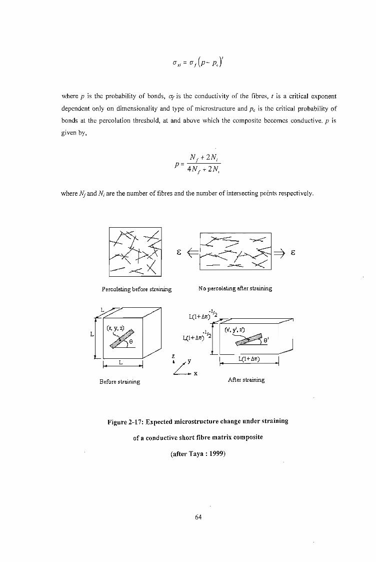
where P is the probability of bonds, OJ is the conductivity of the fibres, t is a critical exponent
dependent only on dimensionality and type of microstructure and Pc is the critical probability of
bonds at the percolation threshold, at and above which the composite becomes conductive. p is
given by,
where NJand Ni are the number of fibres and the number of intersecting points respectively.
-~
Percolating before straining No percolating 8fier straining
-I,L(l+Ae) :2.I,m. y'. z') ,.'
L(IH') lL~.'I~.__L(..:..-1+_A~e),--- ~
z
~x.....I._L__~
L
Before straining After straining
Figure 2-17: Expected microstructure change under straining
of a conductive short fibre matrix composite
(after Taya : 1999)
64

The effective electrical conductivity along the x-axis is then given by,
m
ax =2: by;bZi ax;;=1
where m is the number of percolating clusters and by; (bz;) is the width of the i-th percolating
network along the y (z) axis.
Unfortunately, while the probability theory is accurate for small strains, up to 0.1, with substantial
experimental results presented by Taya (1999) as verification, no results (experimental) are
presented for larger strain values.
Piezoelectric solids exhibit a first order coupling between mechanical stress and electrical potential
with the properties of piezoceramics being sensitive to the presence of impurities and
microstructural features such as grain size and porosity as well as the processing methodology.
Typically, resonant techniques are used along with static and quasi-static tests to determine the
properties of piezoelectric materials, however in some cases, such as thin films and heat sensitive
piezoelectric materials, these techniques can be unusable and one has to resort to instrumented
indentation methods. Giannakopoulos, Ramamurty, Sridhar and Suresh (1999) investigate the
response of lead zirconate titanate piezoelectric ceramics to spherical microindentation. In the
instrumented indentation tests, the indentor load is continuously recorded as a function of the depth
of penetration of the indentor into the material and the information is used to determine material
properties such as Young's modulus, yield strength and the strain hardening exponent for metallic
materials, and strength and fracture toughness for brittle materials.
Theoretical and finite element analysis reveals that the functional relationships between indentor
load and the depth of penetration for the fully coupled problem have the same structure as the
uncoupled mechanical problem. Further, the resistance of the material to penetration by the
indentor depends on the electrical conductivity (i.e. whether open circuit or closed circuit
conditions prevail). Spherical indentors offer the advantage of less complex testing and analysis
over other shapes of indentors because they produce a non-singular stress field (Giannakopoulos et.
aI. : 1999).
In the theoretical analysis the piezoelectric material is considered to be transversely isotropic and
the interface between the spherical indentor and the flat surface of the piezoelectric substrate is
assumed to be frictionless. There are five elastic, two dielectric and three piezoelectric constants
(independent) for a transversely isotropic piezoelectric solid. If the indenting sphere is a perfect
65

electrical conductor with constant electric potential rjJ = rjJo and radius R, then the boundary
conditions at the indented surface are,
~(r,O) = ~o ; 0::; r::; a, Z =0
Dz(r,O) =0, r> a, Z= 0
where rand z are the radial and normal co-ordinate directions schematically shown in Figure 2-18,
D is the electrical charge distribution and a is the radius of the contact area.
(b)
h""--~-=-=---~-- r
-z
Figure 2-18: Schematic representation of the experimental indentation system
(after Giannakopoulos et. aI. : 1999)
The first of these equations indicate that the potential of the sphere is also the potential of the
contact area, while the second equation shows that the electric charge distribution outside the
contact area is zero (external charges are absorbed by the surface or by the use of electrodes).
When rjJo = 0, the relation between indentor load, P, and indentation depth, h, is given by,
66

p = s.fRM4 Ms - M3 M6 hY7.3M
JM4 - M2 M3
where M j through to Ms are related to the material constants (algebraic relationships given in
Giannakopoulos et. aL : 1999).
If the indentor is a perfect insulator with zero electric charge distribution, the boundary condition
is,
and the P-h relationship is expressed as,
p = s.fRMg Ms - M7 M6 hY7.3M1Mg - M2 M7
If the indented material is electrically rigid, i.e. all the coupling constants are equal to zero, then
the constants M3 and M 7 reduce to zero. In the case of purely elastic Hertzian spherical contact, the
P-h relation is given by,
(2 2) -I4 I-v I-v I
where SI ="3 ~+~ Rli and is referred to as the contact compliance. Ej and E2 are
Young's moduli and Vj and V2 are Poisson's ratio of the specimen and indentor respectively.
To take into account the possibility of deformation at the back face of the indentor, the contact
compliance can be redefined as,
67

where S is the total contact compliance and S2 is the contact compliance between the back surface
and the indentor.
The results obtained by Giannakopoulos et. aI. (1999) showed that the elastic modulus of
piezoelectric materials depends on the experimental condition of electrical connectivity between
the two opposite faces upon which external loading is applied. The modulus measured with both
the ends of the specimen electrically connected is generally lower than that measured with an open
circuit. The change in stiffness can be attributed to the additional mechanical resistances offered by
the undissipated potential generated due to the mechanical deformation of the piezoelectric solid.
Although the charge distribution under the indentor cannot be sustained if the contact area is fixed,
the charge build-up increases during the quasi-static advance of the contact area under a steadily
increasing indentation load. If the indentor is conducting and grounded, a charge builds up in the
indentor opposing that developing in the specimen. This distribution of charge, which changes with
time, manifests as a quasi-static electric current.
The majority of analyses characterising piezoelectric actuation of laminates are based on classical
laminate theory that assumes a linear strain distribution 'through the thickness and zero transverse
shear stresses. This theory is restricted to thin plate applications, and to address moderately thick
and thick laminate constructions the effects of transverse shearing stresses need to be taken into
account. Chattopadhyay and Seeley (1997) use a higher order refined displacement field theory to
take into account transverse shear stresses through the thickness to analyse smart materials surface
bonded or embedded in composite laminates. While higher order laminate theories provide an
effective tool to predict the deformation behaviour of composite laminates subjected to bending
loads, the difficulty arises in satisfying the stress free boundary conditions at the free surfaces
while maintaining continuity of strains through the thickness. Further, the electromechanical
coupling coefficients for piezoelectric materials are dependent upon the actual strain in the
actuators and this needs to be taken into account.
If it is assumed that there are no defects in the composite material, such as voids or delaminations,
then the displacement field is continuous. A further assumption is that the in-plane displacements
vary as cubic functions of the thickness z, and the transverse displacement is independent of Z
(Figure 2-19).
68
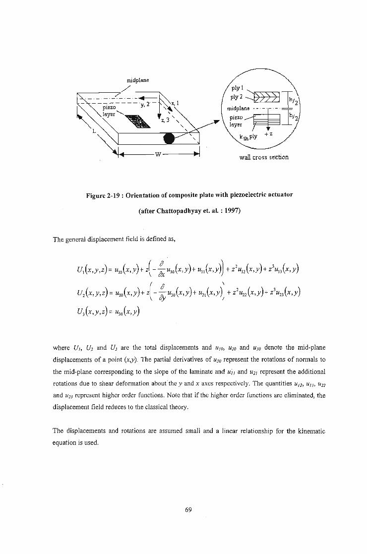
f4-----W----p
ply 1
ply2 ~»)]~/2
";·"1;- -rI--LpiezQ 1h/2layer -l
kthPly + Z
wall cross section
Figure 2-19 : Orientation of composite plate with piezoelectric actuator
(after Chattopadhyay et. al. : 1997)
The general displacement field is defined as,
uJx,y,z) = ulO(x,y) +z( - ~U30(X,y)+ ul1 (x,y)) +Z2 UI2 (X,y)+ Z3UI3 (X,y)
U2(x,y,z) =~o(x,y)+ z(- ~~O(x,y)+ ~1(X'Y)) +Z2~2(X,y)+ Z3U23 (X,y)
U3(x,y,z) = u30 (x,y)
where VI, V2 and V3 are the total displacements and UfO, U20 and U30 denote the mid-plane
displacements of a point (x,y). The partial derivatives of U30 represent the rotations of normals to
the mid-plane corresponding to the slope of the laminate and uj I and U21 represent the additional
rotations due to shear deformation about the y and x axes respectively. The quantities U12, UI3, Un
and U23 represent higher order functions. Note that if the higher order functions are eliminated, the
displacement field reduces to the classical theory.
The displacements and rotations are assumed small and a linear relationship for the kinematic
equation is used.
69

where CJ_6 represent the linear strains.
The forces and moments produced as a result of piezoelectric actuation are also discussed by
Chattopadhyay and Seeley (1997) and the results conclude that for moderately thick and thick
laminates, the higher order theory efficiently captures the localised nature of the stresses near the
actuators while the classical laminate theory showed significant deviations.
Finally, Anderson, Calvert, Denham and Madenci (1997) discuss the sensor response of
polyvinylideneflouride films (PVF2) embedded between layers of composite laminates.
Piezoelectric PVF2 films retain much of their piezoelectric response upon cooling from curing
temperatures up to 200°C, even though the cure temperature exceeds the melting point of the film.
Further, ceramic piezoelectric sheets (e.g. PZT) are available down to a thickness of 250 microns
but are very fragile, with fracture strains of only 0.1 %. They are also susceptible to loss of poling
above the cure temperature, 300°C to 400 °C for PZT, and can depole at stresses of 10 MPa to 100
MPa. Polymer piezoelectric materials (PVF2 and several nylons and copolymers of vinylidene
cyanide) are thinner and tougher but raise concerns about temperature range and the piezoelectric
coefficients are much less than those of the ceramics. Anderson et. al. (1997) monitored the sensor
response during the cure cycle. The sensor response decreased with increasing temperature and
goes to zero in the region of the melting point. The sensor does not respond to stimulus during the
rest of the cure, but does exhibit a reduced piezoelectric response once cooled. This is attributed to
the constraining of the sample during cure. An unconstrained sample subjected to a similar cycle
showed a more rapid loss of response with no return on cooling. The effect of constraint is to raise
the melting temperature of the PVF2 and cause recrystallisation in the piezoelectric beta phase
instead of the non-piezoelectric alpha phase. Load is shared between the embedded PVF2 sensor
and the epoxy matrix on the basis of equal strain.
70

CHAPTER 3
3 ANALYTICAL DESCRIPTION
The sole objective of this chapter is to develop an analytical model that can be used for numerical
simulation, to describe the low velocity impact scenario investigated in this thesis. The scenario
considered is a simply supported beam, of rectangular cross-section, subjected to a falling mass
impact at midspan. The chapter is divided into four subsections in order of increasing material
complexity, Le. a beam consisting only of matrix material is first considered, then the same beam
with shape memory alloy reinforcement is evaluated, followed by the addition of magnetostrictive
inclusions and finally a short write-up on piezoelectric control. Another important output of this
chapter is the derivation of the geometric relationship between the beam displacement and strain.
The implementation ofthe outputs of this chapter into numeric code is presented in Appendix B.
3.1 Impact of Aluminium Host Structure
Consider the initial problem of the simply supported homogenous aluminium beam subjected to a
falling mass impact at midspan, depicted in Figure 3-1 below. The cross-section of the beam is
considered to have a width of b and a depth ofd.
p
/////11-01<~ L_/_2 ~>I< L/2
J
~I7
Figure 3-1 : Schematic of beam impact conditions
The conventional average shear and bending stresses for a simply supported beam with a static
load at mid-span are given by,
71

Pr= -
AP
- bd
and
J.4y(Y= --
IPLd
4 2=[;d3
123PL
=2bd2
respectively, where P is the load, A is the cross-sectional area, M is the bending moment, I is the
second moment of area and L is the length of the beam. y is the distance from the neutral axis of
the beam to the outermost point. Note that these average stresses are presented for information only
and are not used in any calculations. Stresses based on actual displacements and instantaneous
modulus are used when required.
From conventional beam theory, the deflection is given by,
where Eis Young' modulus.
To facilitate numerical modelling, the ability to transform from the force-displacement domain to
the stress-strain domain is crucial. Thus, the transformation equation, in the form of the geometric
relationship between the displacement, 8, and the strain, E, needs to be established. Figure 3-2
presents a schematic of the resultant beam behaviour to the problem depicted in Figure 3-1.
72
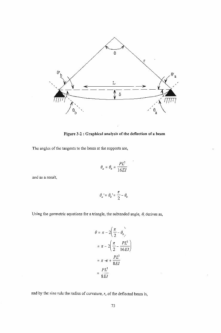
r
Figure 3-2 : Graphical analysis of the deflection of a beam
The angles of the tangents to the beam at the supports are,
and as a result,
Using the geometric equations for a triangle, the subtended angle, (), derives as,
B= re - 2(!!... - BbJ2 ,
= re - 2( ; - l~~lJPL2
=re --jf +--8El
PL2
8El
and by the sine rule the radius of curvature, r, of the deflected beam is,
73

Sin(~- PL2
)2 16El
r = L ----,-----.,.----
(PL2)
SIn 8El
The strain of the beam is defined as the ratio of the change in length to the original length and is
given by,
I1L&= -
Lrf) - L
----L
PL2 • (1! PL2
)SIll ----2 16El
= SEI Sin( :~~) -1
Solving this equation in terms of 0 yields,
& = (¥)sin(%-¥)_I. (60)
SIll T .
where
PL3
0=-48El
It should be noted at this point that this is the strain-displacement relationship for the beam as a
whole and is not representative of the contact area under the impactor. The area directly below the
impacting mass (or in the case of a Charpy test, the area at the notch) experiences a larger value of
localised strain, and it is this higher strain that is responsible for initiating material failure. Thus, a
strain factor is introduced that takes into account this localised strain. The strain factor, EfaclO" is
considered to be a physical quantity dependent on the length of the beam, the beam cross-section
(second moment of area), the contact area of the impactor and the impacting energy. Thus,
74

I 28, =k--mv
jac/ar LA 3
where k is the proportionality constant, I is the second moment of area, L is the beam length, A is
the contact area, m is the mass and v is the impact velocity.
Since the strain factor is dependent only on the physics of the system and not on the material, once
the value has been determined, it can be fixed for a particular set-up. This is useful for the current
investigation since the test set-up remains unchanged from the normal composite to the smart
composite analysis.
Also, it is important to remember at this point that in current theory, aluminium does not have a
definable yield point (see Figure 3-3) and hence, the conventional strain value of 0.2 % is used to
distinguish between the elastic and plastic regions of deformation. This assumption is not
necessary when using the damage modulus method of analysis described earlier.
cr I/
/I
0.2% emu
Figure 3-3 : Typical stress-strain curve for aluminium
Now, given the impact velocity of a free-falling projectile of mass, m, the height, h, through which
the mass has to fall can easily be calculated as (Figure 3-4),
75

m '
.~
h
Figure 3-4 : Schematic of impact due to falling mass
I71TI
In considering the energy absorption of the beam, the analysis is separated into an elastic
component and a plastic component. For the elastic component, the time t = 0 is when the mass
contacts with the beam.
For now, the assumption is made that the mass does not slow down once it impacts the beam and
hence the displacement of the beam is given as,
0= vt
=.j2gh t
The time for the beam to reach a state of plasticity is determined by using the plasticity strain and
rate of displacement given in the preceding equations.
&~ (¥}m(%-¥)_1. (60)
Sill L
76
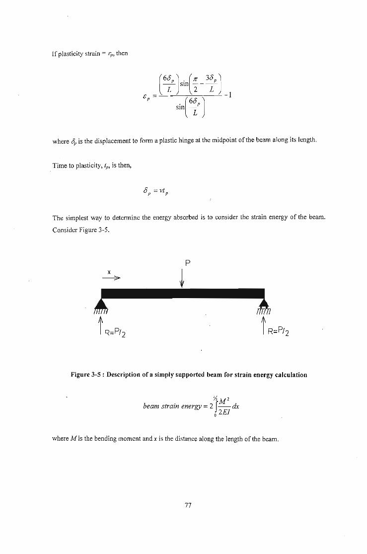
If plasticity strain = cp , then
. where op is the displacement to form a plastic hinge at the midpoint of the beam along its length.
Time to plasticity, fp, is then,
The simplest way to determine the energy absorbed is to consider the strain energy of the beam.
Consider Figure 3-5.
p
~
Figure 3-5 : Description of a simply supported beam for strain energy calculation
y, M 2
beam strain energy = 2 f-- dxo 2E1
where M is the bending moment and x is the distance along the length of the beam.
77

Y,(Rxybeam strain energy =2f-- dx
o 2E1
2R 2 x 3 y,=----
2E1 3 o
. R PSlllce = -.2
However, this is only representative of the elastic deformation of the beam, and in a Charpy test,
around which this theory is developed, the beam is stressed to beyond its elastic limit to ultimate
failure. Thus, it is not enough to simply use the elastic strain energy of the beam, and the entire
work done on the beam needs to be considered, i.e.
o@ultimatefailureEnergy =Work = JPdo
0=0
Further, to achieve a more realistic characterisation of the energy absorption, the beam resistance
and decrease in the velocity of the mass need to be taken into account. Consider an arbitrary time t,
during the elastic range of deformation. The mass has a velocity of v and an associated energy of
t mv2• After time interval dt, and ignoring the effects of potential energy due to the change in 6, to
simplify the analysis, the energy state ofthe mass is,
Energymass = tmv2 - f...Work done on beam
=tmv2 -Podt
= tmv2 -Pvdt
Note that the energy balance equation excludes contact energy dissipation, as it was not measured
in the experimental work on which the model is based. This has been done to enable model
verification and a more accurate comparison between energy absorption capacities.
This energy must now be associated with its new velocity, VI, to comply with the conservation of
energy law. Thus,
78

tmv? = tmv2 - Pvdt
V 2 = V 2 _ 2P vdt1 m
v~ _v 2 2P-,---=--dt
v m
Solving for the characteristics of velocity yields,
V 2 _V2 2P
1 =--dtv m
=_ (2)(48)E1 &itmL3 .
=_(2)(48)E1 vtdtmL3
v2- v2 (2)(48)E1 d
I = 3 t tv2 mL
1 2 2k-dv =--tdtv2 m
Integrating both sides,
2k t 2
Inv2 =---+cm 2
whereA=ec•
@ t=O, V=Vo (impact velocity) and A=v/. Thus,
The displacement of the beam, taking into account strain energy absorption, is given by,
79

O=vt
The energy during the elastic range now assumes the form of,
Energy = fPdO
=f48~I &10L'
f48EI 2 _£(2
= -- v e m tvdtL3 0
= f48EIL3
f48EI 2 _£(2= --ve m tdtL3 0
Further, the load P, can be calculated from the stress in the beam as,
My0'=-
I
M=PL4
P= 40'1yL
Assuming that the changes in Land b are negligible,
2abd 2
P=-3L
It is important to note that when the elastic point is exceeded and plasticity commences, the beam
no longer offers resistance to the load and the energy absorption increases as the beam deforms
plastically to the breaking point. At this stage, there are two important considerations. Firstly, if the
shape of the stress-strain curve, Figure 3-3, is considered, it is evident that the energy absorbed in
the plastic region is greater than the energy absorbed in the elastic region of deformation, i.e. the
area under the elastic portion of the curve is less than that under the plastic portion of the curve.
80

Secondly, from the onset of plastic deformation, the depth of the beam is no longer constant and
decreases until the remaining cross-sectional area is no longer sufficient to support the external
load in shear. Thus, the final depth of the beam before ultimate failure is given by,
Loaddepthjinal = ( X)Beam Strength Width
Combining the elastic and plastic regions results in the total energy absorption of equation form
below.
3.2 SMA Unidirectional Reinforced Aluminium
In modelling a unidirectional composite, several assumptions have to be made. Fibres are assumed
to be unidirectionally distributed throughout the composite, have uniform properties and diameters
and be perfectly bonded to the matrix. Perfect bonding implies that the fibre strains, matrix strains
and composite strains are all equal.
Thus,
where the subscripts c, m andf refer to the composite, matrix and fibre respectively.
Further, to ensure a fibre controlled composite failure the fibre volume fraction, vf ' must be equal
to or greater than,
where O"mu is the matrix ultimate strength, Oju is the fibre ultimate strength and (J1t1)' is the matrix£/
stress at fibre fracture strain.
81
Assume for the moment that the velocity on impact remains constant through the region of strain
from zero to the SMA transformation strain. Once again, the velocity on impact is,
and the displacement ofthe beam is given by,
cS =vt
PL3
=~2ght=48EI
The load is obtained from,
My(J =-
C 1
PLd---
81
where d is defined earlier as the depth of the beam.
Using the assumption of perfect bonding, the stress in the fibre is solved for as follows,
or (5f =£Ef where & is determined from the displacement of the beam. When the fibre strain
equals the transformation strain, Yr, the stress in the composite is,
(J = GjECT C
where (J is the stress in the composite at the transformation point.CT
Once the composite transformation stress is obtained, the transformation load can be solved from,
82

The energy absorption of the beam up to the point of transformation is,
Energy = fPdb'
= j48EI(.J2ihr tdt I=I
T
L3
1=0
If the decreasing velocity of the mass is taken into account then,
and the energy absorption becomes,
This is similar to the energy absorption of the un-reinforced aluminium host beam derived earlier.
For the energy absorption characteristics in the transformation environment, i.e. r T ::; & ::; r Tmax'
(where rT is the transformation strain and rTmax is the maximum transformation strain), the physical
properties of the composite is based on the martensitic fraction which in turn is based on the strain
of the SMA fibres. The general description of the martensitic transformation in SMA is depicted in
Figure 3-6.
83

Martensite Finish
MartensiteStart
Austeni te Start
AusteniteFinish
STRAThr
Figure 3-6 : General description of the SMA transformation process
Since it is evident from Figure 3-6 that the strain is linear from YT to YT max, the martensitic fraction
is also assumed linear from 0 % to 100 %. Thus,
& - YTFM=--~-
YTmax- YT
where FM is the martensitic fraction.
If it is further assumed that the properties of the SMA fibres vary linearly from the austenitic phase
to the martensitic phase according to the martensitic fraction then,
where EjM is the modulus of the fibre in the martensitic phase and EjA is the modulus of the fibre in
the austenitic phase.
The velocity of the transformation point is,
and applying the energy balance equation for strain energy results in,
84

The displacement is given by 0 = vt and the modulus of the composite by,
Ee =vfEf +(1- vf )Em
= vr[EfA - FM(EfA - EjM)] +(1- vf)Em
=Vf[EfA - E-~T (EfA -EjM)]+(l-Vf )EmrTmax rT
An analysis of the energy absorption yields,
I 2 481 {[ g(8}- Yr (E E)] (1 )!E }d~ _I 2Energy =zmv --3-8 vf E fA - _ fA - jM + - V j m U - Zmv\L YTmax YT
481 {[ g(vt} - YT ( )] ( )} d I 2tmv2 --3-Vt Vj E fA - _ EfA -EjM + 1-vf Em V t =zmv1
L Yrmax Yr
1 (2 ·2) 481 2{ [ g(vt}-Yr(E E)] (1 \r.o}dzmv1 -v =-3V Vf EfA - _ jA- jM + -VfJCm t tL Yrmax YT
_1 dv2 = (2)(48)1 {V [E - g(vt}-Yr (E -E )]+(l-V)E }tdt2 L3 f fA fA jM f m
V m Yrmax - Yr
Integrating this expression and solving for v results in ~ = f(t) + D, where D is a constant. The
energy absorbed during this transformation stage is thus,
E f48EJ ~dS:nergy = --3-u uL
where (j = vt.
If, during transformation, the displacement is kept constant, the force increases to account for the
energy required for martensitic conversion. Thus, the energy graph during this stage should be
similar to the pure aluminium beam, only greater in magnitude, i.e., Figure 3-7, for example,
85

E
o
SMA
Aluminiumalloy
t
Figure 3-7 : Energy of SMA reinforced aluminium
during the transformation stage
After the martensitic transformation, ( rT max ~ 8 ~ 8 foi! where Bfoi! is the failure strain), since
the composite is governed by a fibre controlled failure, the material continues to bear load until the
strain in the fibre reaches the ultimate martensitic fracture strain, at which point the material fails.
The velocity at the end of transformation is v = f(t) at FM = 1. The material has a new Young's
modulus and is assumed to react in a conventional manner once again. The analysis for post
transformation is thus similar to the pre-transformation analysis, i.e.,
p= 8IaLd
and
Energy = fPd8
with 8 =vI , where v =
the change in E.
2 -!:ot'Vote no and Vot = velocity at Fm = 1 and k' = new stiffness value due to
3.3 .Magnetostrictive Unidirectional Fibre Inclusions in SMA Unidirectional
Reinforced Aluminium
Once again, perfect bonding between the matrix and fibres is assumed, resulting in equal strains
across the composite. Further, the total volume fraction of the fibres is kept constant to that
86

determined in section 3.2 to enable valid comparison of energy absorption and energy absorption
rates between the materials, i.e.
where vfSMA and vfMag are the SMA fibre volume fraction and magnetostrictive fibre volume
fraction respectively.
The initial orientation of the magnetic field is in the direction orthogonal to the fibre axis as shown
in Figure 3-8.
Fibre
.Magnetic field
Figure 3-8 : Initial magnetic field orientation in magnetostrictive fibres
If the magnetostrictive material is activated as soon as impact occurs, then the strain in the
composite is given by,
where CTOT is the total strain in the composite, CL is the strain due to the external load and CMag is the
strain due to the magnetostrictive inclusions.
Consider first the range of strain from zero to the point of transformation. The magnetic strain
component is constant and is given by,
3As (H2 1)&Mag = 2 H~ - 3" = const
where H, HA and As have been previously defined in Chapter 2.
87

For simplification of analysis, it is assumed that the beam is simply supported with quasistatic
magnetic loading. Thus, the magnetically induced strain has no resulting deflection, but causes a
prestress condition in the beam. From the previous analysis and combining stresses,
The Young's modulus ofthe composite is determined by,
where EjSMA and EjMag are the modulus of the SMA fibre and magnetostrictive fibre respectively.
Solving for load results in,
Thus, the resulting energy absorption is given in Figure 3-9,
E
SMA + Mag
E2 - - - - -
o
1I1
I-----.------I
-.., SMA
t
Figure 3-9 : Energy absorption as a result of magnetostrictive
inclusion before SMA transition
88

mechanism to activate a preset magnetic field strength, facilitating immediate maximum strain
within the magnetostrictive fibres.
While this method is theoretically feasible, care must be exercised in the selection of the
piezoelectric layer material and geometry. The sensor forms the surface that receives the impact,
and the resulting initial load and indentation must be tolerable by the piezoelectric surface in terms
of fracture toughness. A material and geometry of too low fracture toughness will crack and
severely impair, if not completely sever, the output of the electromagnet. Further, the piezoelectric
layer needs to be flexible enough to accommodate a strain that will ensure completion of the SMA
transformation process. This is vital to achieve the maximum benefit of the SMA inclusions. As
already stated in section 2.4, linear piezoelectric theory deals with small displacement and
structural vibrations, and assumes quasi-static motion indicating that the mechanical and electric
forces are balanced at any given constant. The non-linear theory deals with the dynamics of
anisotropic piezoelectrics undergoing large displacements. Thus, to be able to model the current
experimental configuration, non-linear theory needs to be adopted. This on its own forms a
complex and detailed analysis that is beyond the scope ~d objectives of this investigation.
91

CHAPTER 4
4 DISCUSSION OF RESULTS
The objective of this chapter is not just a discussion of the results obtained through numerical
modelling, but rather, a discussion of all work undertaken and results achieved throughout the
course of this investigation. Thus, an important outcome of this chapter is a clear differentiation
between the author's own work and that which is borrowed from other sources to help in the
achievement of the fmal objective.
4.1 General
The primary objective of this study is to develop a useable model for predicting the response of
smart materials to impact loading. The response that is considered the focus of the investigation is
energy absorption, with the load response being used as the preferred methodology. The specific
material chosen is a unidirectional, fibrous metal matrix composite with aluminium as the host
substrate and nitinol as the reinforcement. Table 4-1 ,highlights the critical properties of the
materials used in the current investigation.
Table 4-1: Properties of materials used in this investigation
Material Property
Young's Ultimate Tensile Shape Memory Failure
Modulus [GPa] Strength [MPa] Transition Strains [%] Strain [%]
Aluminium AC8A 73 265 - - 1.14
Aluminium Oxide 310 2000 - - 0.64
Nitinol 30 (A) I 13 (M) 1600 2.21 * 7.97** 14.5
* This is the stram at the start of the martenslte phase transformatiOn.
** This is the strain at the end of the martensite phase transformation.
The literature review of Chapter 2 is used as the foundation of this thesis and represents the
author's interpretation of the various articles. As is evident from Chapter 2, there is very little
published information that can be used directly, especially in terms of analytical models. The
literature review thus serves as a means of developing a broad understanding, physically, of
various individual components of the study, viz. microstructural behaviour of SMA, general impact
92

loading phenomenon, general behaviour of composite materials (interactive behaviour between
elements), as well as magnetostrictive and piezoelectric phenomenon.
The literature review also highlights the need for a robust analytical model that can simplify the
predictions of material response of metal matrix SMA specifically, and complex materials in
general. Thus, the theoretical characterisation of the system presented in Chapter 3 forms the heart
of the study, and the simple, yet profound concepts proposed are completely the individual work of
the author. An extension of the author's individual work, and coupled to this unique theoretical
characterisation, is the software code to numerically simplify the analytical model. The code is
developed in conjunction with the literature review, i.e. the fundamental interactive behaviour of
the various components is used to promote a logical and realistic interpretation of the proposed
theory.
The reader's attention is now drawn to the results of the numerical analyses. All the results
presented from this point onward are the sole effort of the author, with the exception of the
comparative results of section 4.4. While the model predicted results are that of the author, the
experimental results are those of Aggag et. al. and have been so accredited.
4.2 Damage Modulus
At this point the reader is asked to reflect upon the concept of the elastic modulus, or Young's
modulus, E. Young's modulus is so called after the English scientist Thomas Young, who
introduced the idea of a 'modulus of elasticity' after investigations of tension and compression of
prismatic bars. The modulus itself has since been refined and is in effect the slope of the stress
strain diagram in the linearly elastic region of a material. From its humble beginnings, the elastic
modulus has become a corner stone of modem mechanical design engineering, the most important
consequence being the formulation of Hooke's law.
Hooke's law characterises the linear relationship between applied load and the resulting
elongations. The most common equation, CJ =£8, is a limited version as it relates only to the
normal stresses and strains developed in simple tension and compression. The generalised Hooke's
law is the equations for three-dimensional stress-strain relationships. Unfortunately, all the
resultant simplifications of Hooke's law and the modulus of elasticity are limited to a definite
range of a materials stress-strain cycle. Consequently, the majority of engineering designs have
also become limited to this finite 'operating range' of a material and thus, the full capability of a
93

material is not utilised. Imagine the impact of such a concept in the plastic range of a material's
behaviour, or of a single factor that incorporates both elastic and plastic material responses!
This 'modulus of plasticity' is referred to in this text as the damage modulus, ED . It may even be
considered as a 'modulus of elasto-plasticity' as it incorporates elastic material behaviour as well.
Advantages of ED are that it extends Hooke's law to beyond the elastic limit of a material right up
to the point of ultimate failure and it is applicable to most, if not all, materials, including ductile
materials, brittle materials and exotic materials such as SMA as indicated in the figures below.
Further, no new testing of materials is required as ED is derived directly from existing material
stress-strain relationships.
The concept of stiffness (modulus) degradation is not new. Kachanov initially proposed it in 1958
in terms of scalar damage concept that is based on the ratio of damage area and nominal area. Since
then a number of damage formulations have appeared in the literature. While the manner in which
these formulations implement the damage parameter is different (Bazant and Jirasek: 2002), the
underlying concept is the same, i.e. the damage parameter is a complex derivation that is used to
modify the nominal stress-strain diagram. The damage modulus, ED, proposed in this investigation
is unique firstly in its simplicity and secondly in that it does not change the material's nominal
stress-strain diagram, but is in fact derived from it. Figures 4-1 and 4-2 show the derived damage
modulus for an aluminium alloy, AC8A, and resulting stress-strain diagram, respectively, based on
an extension ofHooke's law.
AC8A MODULUS80
70
~
~ 60en::l...J::l
El 50::!ELJ.JCJ~ 40<l:Cl
30
200.80 0.2 0.4 0.6
STRAIN [%]
1.2 1.4
Figure 4-1: Damage modulus for AC8A aluminium alloy
94

AC8A STRESS-STRAIN CURVE300,.----,----,----,---,---,---.,----,
250
200
1.41.20.6 0.8STRAIN [%1
0.40.2
L.-__'---__'---__-'--__l.__---L__---L__--'
cac..~(fJ 150(fJwf!:(fJ
100
Figure 4-2: Stress-strain curve for AC8A aluminium alloy
The characteristic that is immediately apparent in Figure 4-1 is that there is a clear distinction
between the elastic and plastic behavioural regions of the material. The initial constant region of ED
characterises the elastic material behaviour and is equivalent to Young's modulus, while the
subsequent region characterises the material beyond the elastic limit. The reader's attention is
directed to the deceasing value of ED in the latter region of Figure 4-1 that corresponds to, very
critically, a decreasing capacity of the material to sustain further load. This is a very important
feature of the damage modulus as it takes into account degradation of the material through the
plastic region, up to the point just before ultimate failure. Thus, ED lends itself to the simplification
of many damage models in terms of a reducing sustainable load and energy absorption capacity.
Only the energy consumed through material rupture remains to be characterised.
Figure 4-3 shows the derived damage modulus for aluminium oxide (Ah03). Aluminium oxide is a
brittle material and does not undergo plastic deformation on a macro, bulk material level. Thus
Figure 4-3 reflects a constant ED that corresponds to the materials Young's modulus.
95
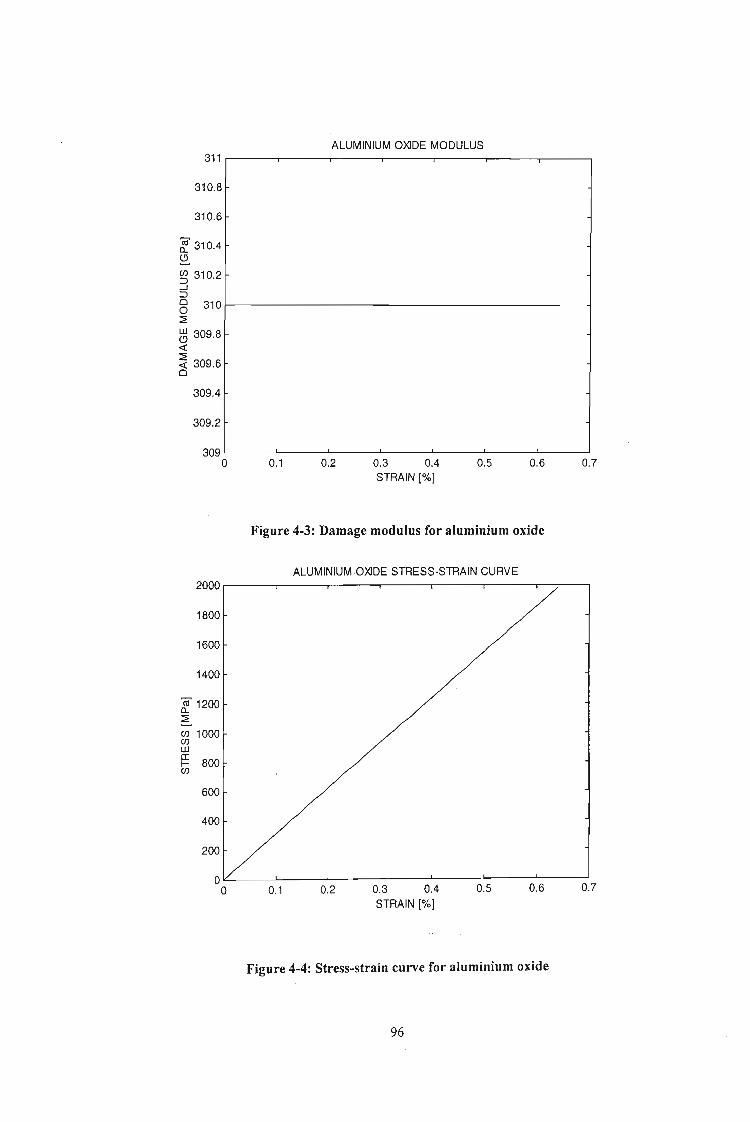
ALUMINIUM OXIDE MODULUS311 r-----,-----r-----,---.------,---~--_____,
310.8
310.6
~ 310.4~
~ 310.2...J~
Cl 3101-----------------------o::::E
~ 309.8«::::E« 309.6Cl
309.4
309.2
0.70.60.50.3 0.4STRAIN [%]
0.20.1
309 l-__..L--__--'--__--' -'--__..L--__--L.__----.J
o
Figure 4-3: Damage modulus for aluminium oxide
ALUMINIUM OXIDE STRESS-STRAIN CURVE2000,---,----r----,----,--.......----,--;-----,
1800
1600
1400
8!. 1200::::E
Cl) 1000Cl)w~ 800Cl)
600
400
200
01L..-__L-__L-__L-__L-__.l.-__-'--- __
o 0.1 0.2 0.3 0.4 0.5 0.6 0.7STRAIN [%]
Figure 4-4: Stress-strain curve for aluminium oxide
96

The stress-strain curve of Figure 4-4 reinforces this purely elastic behaviour of Alz0 3• The constant
nature of the ED-f. graph also shows that no material degradation is present during loading and that
the rate of energy absorption is constant up to the point just before material rupture. This type of
material behaviour helps to intuitively understand this new concept of ED taking into account
material degradation (damage) and apply this understanding to the damage modulus curve of
AC8A (Figure 4-1).
The damage modulus curve and corresponding stress-strain diagram for the SMA, nitinol, are
shown in Figures 4-5 and 4-6 respectively.
NITINOL MODULUS55,.----------.---------,----------,
50
45
~ 40a..Q.gj 35--.J:::lo 30o~
ttJ 25«~ 20o
15
10
5L- --l.. --'- --J
o 5 10 15STRAIN [%]
Figure 4-5: Damage modulus for nitinol
In this case, the first half of the ED curve is very similar to Figure 4-1 (the ED curve for AC8A), and
is typical of similarly behaving materials. The initial constant ED reflects Young's modulus and the
subsequent decreasing ED behaviour shows material degradation and damage. However, at
approximately 8% strain, the shape memory response of nitinol takes effect resulting in a unique
corresponding change in the materials ED. During the shape memory transition phase, the stress
strain curve indicates a constant rate of change, similar to the initial Young's modulus rate. The
corresponding phase in the ED diagram interestingly does not reflect a constant specific value (as
during the Young's modulus phase), but rather a constant differential. What is the significance of
this trend? This trend emphasizes the close relationship between ED and material energy absorption
97

NITINOL STRESS-STRAIN CURVE1600 r-------....----------.--------
1400
1200
ro 1000a..~
en 800enwg:en
15105
OL.-.--- ----l ----l ---J
oSTRAIN [%]
Figure 4-6: Stress-strain curve for nitinol
/ material degradation or damage discussed earlier, i.e. the increase in ED during the shape memory
transition phase indicates 'repair' of the materials properties or an increase in its energy absorption
capacity. Once the shape memory transition is complete, the 'new' material properties begin to
degrade and lose energy absorption capacity indicated by the corresponding decrease in ED . Again,
the only damage I energy that still needs to be considered is ultimate rupture of the material.
The author firmly believes that this new concept of a damage modulus will have enormous impact
in many branches and fields of mechanical and material studies. The full consequences of ED on
other fields of study, however, is not the ultimate objective of this thesis and the author is of the
opinion that adequate substantiation of this concept has been given to establish credibility to the
reader. The damage modulus is an exciting new development that can one day lead to the full
characterisation of a material, through its entire functional strain range, by simple equations
currently only applicable up to the elastic limit.
4.3 Model Setup
Figure 3-1 describes the example used to demonstrate ED as well as to investigate the energy
absorption characteristics of SMA reinforced metal matrix composites. It is a simply supported
98

beam subjected to a falling mass impact load, and Chapter 3 describes the appropriate theory
necessary to fully characterise the system kinematically. The reader will notice that this chapter is
divided into four sub-sections, beginning with the most basic set-up and then proceeding in stages
of increasing material complexity, i.e. the response of a pure aluminium beam is first characterised,
followed by the response of a SMA reinforced aluminium matrix composite beam, then the
composite beam with magnetostrictive inclusions and finally, an excerpt on piezoelectric control.
Along with the basic elastic stress / strength theory of the faIling mass impact analysis, and the
author emphasises the point that low velocity impact is only considered, the basic analysis of the
pure aluminium beam also highlights three important considerations. The first is the geometric
relationship between the two-dimensional beam displacement during the impact process to ~he one
dimensional longitudinal strain of the beam. This is very important as it facilitates the crossover
from the load-displacement domain to the stress-strain domain, thus enabling the point of plasticity
to be correctly determined from the material stress-strain curve. This transition also gives the
author the opportunity to demonstrate the simplicity and capability of ED . The second important
consideration is the effect of the beam strain energy on the velocity of the falling mass. The
velocity-displacement profile that is derived is based on the conservation of energy principle and
demonstrates the integrity of the model in describing a real system. The effect of air resistance on
the energy balance of the system is ignored and the effect of potential energy variation due to beam
displacement is considered negligible. The velocity-displacement derivation yields an exponential
relationship dependent on the stiffness of the beam, the mass of the projectile and the displacement
/ strain in the material (described in terms of time for simplification). Finally, this sub-section also
explores, qualitatively, the amount of energy absorbed elastically compared to plastic energy
absorption.
In the SMA reinforced composite analysis, the first part is devoted to basic and longitudinally
reinforced fibrous composite theory, as well as application of the derived relationships discussed in
the preceding paragraph. The crucial aspect of this part of the analysis is the consideration of the
shape memory transition phase. In the current model, the author makes use of the previously
considered (by other investigations and authors) concept ofmartensitic fraction. To compensate for
a lack of publications in this area, and to simplify the analysis, the assumption is made that the
properties of the SMA fibres vary linearly according to the martensitic fraction. However, it must
be noted that by use of the damage modulus, the change in fibre properties is inherently
incorporated, as ED is based on the materials experimental stress-strain curve. Finally, this analysis
sub-section ends with a derivation of the velocity-displacement relationship for a metal matrix
SMA reinforced composite beam and includes characterisation through the transformation phase,
another unique contribution by the author.
99

The analyses of the magnetostrictive and piezoelectric smart materials is very much limited in
comparison to the previous two characterisations. For this discussion purposes, it is enough to say
that only basic magnetostrictive theory is presented, but it is sufficient to draw the conclusion that
the effect of magnetostrictive inclusions in the SMA reinforced composite can be taken into
account by applying varying degrees of prestrain to the composite beam, to simulate varying
degrees of magnetic field. Again, a velocity-displacement relationship is presented. No theoretical
description is put forward for piezoelectric materials as the author has decided to exclude it as part
of the fundamental investigation; however, a brief description of a possible control method for the
magnetostrictive inclusions in the beam is presented.
4.4 Model Verification by Numerical Analysis
Numerical simulation has been employed as a means of solving the proposed analytical model for
a given set of conditions. Matlab is the simulation software of choice, primarily because the author
is familiar with the coding structure and capabilities. The author further believes that a line-by-line
discussion of the code (presented in Appendix B) is not required and only key points are
highlighted.
The first part of the code is used to define the various material properties, most important being the
damage modulus for the aluminium alloy matrix, aluminium oxide fibre, SMA fibre and the
resultant composite. At this point the reader is asked to recognise that all reference to 'modulus' in
the code is reference to the damage modulus of the indicated material. Further on the point ofED, it
should be noted that the moduli are approximated by a series of consecutive straight lines to help
with discretization and simplify the solution of the model.
After defining the damage modulus, the code proceeds to solve the analytical model in 'discreet
time intervals. The methodology is as follows: The velocity at the beginning of the time interval is
determined by subtracting the energy absorbed by the beam in the previous time interval from the
total kinetic energy of the mass. This calculated velocity is then used to produce a discreet
displacement through the current time interval, which in turn is transferred into the strain domain
through the displacement-strain transformation equation discussed earlier. The resulting stress is
determined by use of the equivalent damage modulus of the composite at that particular value of
strain. The composite stress is converted, by geometric relations, into loads supported by the
various components, Le. the matrix, Ah03 fibres and SMA fibres, which are finally used to
determine the corresponding energy absorptions.
100

The final part of the code deals with determining failure of the system. The system is considered to
have failed when either the stress in the composite reaches its maximum calculated strength or
when the fibre strain exceeds its ultimate strain (depending on fibre volume fractions, either the
Ah0 3 fibre or nitinol fibre ultimate strain is used). Once the system has failed, the stress and strain
is kept constant and the depth of the beam is allowed to decrease in a predetermined manner up to
a specific value (both determined during the model verification phase) at which point complete
rupture of the remaining section of the beam is assumed to take place.
With the model code now in place, the next step in the methodology is to refine the model to make
it representative of the physical environment. Specifically, the strength factor, strain factor,
geometric factor and depth factor (described in the methodology section of Chapter 1) is defined
using real data. Experimental results obtained by Aggag et. al. on the falling mass impact of 15%
Ab03 fibre reinforced AC8A aluminium alloy is the closest work that could be sourced from
available literature and is used to set the relevant factors for that stage of the model. These factors
remain unchanged when carried through to the SMA investigation.
The results of the model verification are shown in Figures 4-7 and 4-8. Consider first the load
displacement diagram of Figure 4-7.
MODEL VERIFICATION3000
Theoretical ModelExperimental Results
2500.'
2000 /[i
Z:;; 1500t1l0
...J
1000
500
00 0.05 0.1 0.15 0.2 0.25 0.3 0.35
Displacement [mm]
Figure 4-7 : Model verification - Experimental and predicted load-displacement
results for an impact velocity of 1 m/s (modified after Aggag et. al.)
101

It is clearly evident that the theoretical model accurately describes the experimental trend in terms
of shape of the curve, maximum load reached, strain at maximum load and maximum strain.
Examining the shape of the curve yields an initial exponential increase in load followed by a phase
of constant load increase up to a definite point and then a sudden decrease in load to zero. The
initial exponential growth is as a result of both the matrix and fibre experiencing strain in the
constant modulus regions of their respective stress-strain diagrams. Once the constant modulus
strain of the matrix is exceeded, the matrix modulus (rate of change of stress) decreases and halts
the exponential growth in load capacity to one that appears more linear, up to a point of maximum
load capability. Interestingly, this specific point of sudden decrease in sustainable load does not
only correspond to the ultimate failure strain of the composite, but also the plasticity strain (0.2 %
proof stress) of the matrix.
The strain energy-displacement graph of Figure 4-8 also shows a close following of the model to
the experimental data curves, with the theoretical model predicting a lower total energy absorbed
by the beam. This difference in energy is attributed to the material rupture energy, which the model
does not take into consideration. So far as shape of the curve is concerned, it is similar to the load
displacement curve, as expected.
MODEL VERIFICATION
0.35 r-;::::===::;:====::!::====~---'-----'--------'---:---Theoretical ModelExperimental Results
0.3
0.25
2:15; 0.2IDcw.~ 0.15
i'i5
0.1
0.05
ol-_-='===::::.:---'-__--'-__-'-__..L-_--::-'-:-_ __::_'o 0.05 0.1 0.15 0.2 0.25 0.3 0.35
Displacement [mm]
Figure 4-8 : Model verification - Experimental and predicted energy-displacement
results for an impact velocity of 1 m/s (modified after Aggag et. aI.)
102

The notable difference is that at the point of composite failure (and matrix plasticity), unlike the
load curve that experiences a sudden decrease, the strain energy curve continues increasing,
because of the additional work required in plastically deforming the beam, before levelling off to a
final value.
4.5 SMA Response and Characterisation
With the integrity, accuracy and robustness of the model being verified in section 4.4, the thesis
proceeds to the investigation of its primary objectives, i.e. to determine the effect of SMA in
energy absorption during low velocity impact loading. At this level of the investigation relevant
external publications are scarce; the author could not source even a single article that can be used
as a comparison and discussion tool, despite an extensive literature review. Thus, the discussion of
results is based purely on sound knowledge of individual component behaviour, logical reasoning
and extrapolation of established trends and understanding.
Figures 4-9 and 4-10 show an example of the load and strain energy response, respectively, of a
metal matrix composite beam with SMA inclusions. A 4% SMA volume fraction, out of a total
fibre volume fraction of 15%, is chosen for illustration.
LOAD CHARACTERISTICS OF SMA COMPOSITES3000 r---...,..----,-----,----.------,-----,-----,
2500
2000
z:; 1500ell
.9
1000
500
0.350.30.1O'-"""'---'-----'----'-----L.__---'-__---J_~--.J
o 0.05
103
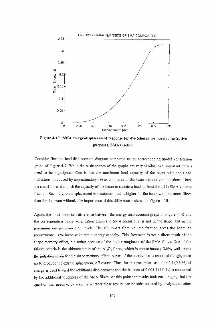
ENERGY CHARACTERISTICS OF SMA COMPOSITES0.35.---r----r----,........--,........--,....-..__-.-__
0.3
0.25
2:6l 0.2Q;c
W
.~ 0.15
U5
0.1
0.05
0.350.30.15 0.2 0.25Displacement [mm]
0.10.05OL..---==:::::...---'-------'-__--'--__--'-__--'__--.Jo
Figure 4-10 : SMA energy-displacement response for 4% (chosen for purely illustrative
purposes) SMA fraction
Consider fIrst the load-displacement diagram compared to the corresponding model verification
graph of Figure 4-7. While the basic shapes of the graphs are very similar, two important details
need to be highlighted. One is that the maximum load capacity of the beam with the SMA
inclusions is reduced by approximately 4% as compared to the beam without the inclusions. Thus,
the smart fIbres diminish the capacity of the beam to sustain a load, at least for a 4% SMA volume
fraction. Secondly, the displacement to maximum load is higher for the beam with the smart fIbres
than for the beam without. The importance of this difference is shown in Figure 4-10.
Again, the most important difference between the energy-displacement graph of Figure 4-10 and
the corresponding model verification graph (no SMA inclusions) is not in the shape, but in the
maximum energy absorption levels. The 4% smart fibre volume fraction gives the beam an
approximate 1.6% increase in strain energy capacity. This, however, is not a direct result of the
shape memory effect, but rather because of the higher toughness of the SMA fibres. One of the
failure criteria is the ultimate strain of the Ah03 fIbres, which is approximately 0.6%, well below
the initiation strain for the shape memory effect. A part of the energy that is absorbed though, must
go to produce the extra displacement, off course. Thus, for this particular case, 0.002 J (0.6 %) of
energy is used toward the additional displacement and the balance of 0.005 J (1.0 %) is consumed
by the additional toughness of the SMA fibres. At this point the results look encouraging, but the
question that needs to be asked is whether these results can be substantiated by analyses of other
104

SMA volume fractions, the results of which must form a definite trend and not be of an arbitrary
(random) nature. Further, the effect of SMA transformation on energy absorption still needs to be
determined.
The analysis of the effect of varying SMA volume fractions has been conducted and the results for
the load and energy trends are depicted in Figure 4-11 and 4-12 respectively. As is evident from
Figure 4-11, there is a definite trend of decreasing load capacity with increasing SMA volume
fraction, which the author attributes to the lower strength of the nitinol fibres as compared to the
aluminium oxide fibres. The nitinol fibre maximum strength is 20% lower than the aluminium
oxide fibre maximum strength. Also evident from the Figure is that there are two clearly
identifiable rates of load decrease; while there is only a 5% decrease in load capacity from 0%
SMA volume fraction to 6% SMA volume fraction, there is a significantly higher decrease in load
capacity (16%) between 6% and 10% SMA volume fractions.
EFFECT OF SMA FRACTION ON LOAD CAPACITY
3000
2500
.... 2000z....-g 1500o
...J 1000
500
oo 0.02 0.04 0.06
SMA Fraction
0.08 0.1
Figure 4-11 : Load capacity characteristics of varying SMA volume fractions
for an impact velocity of 1 m/s
105

EFFECT OF SMA FRACTION ON ENERGYABSORPTION
0.36
0.35
..... 0.342>. 0.332'Cl) 0.32l:
w 0.31
0.3
0.29
o 0.02 0.04 0.06
SMA Fraction
0.08 0.1 0.12
Figure 4-12 : Energy absorption characteristics of varying SMA volume fractions
for an impact velocity of 1 m/s
Figure 4-12 is similar in trend in that there is an increase in energy absorption levels up to a turning
point of 6% SMA volume fraction, followed by a definite decreasing energy absorption trend. The
reason behind this 6% SMA volume fraction turning point is a change in failure mechanism. Up to
6% SMA volume fraction the beam fails because its ultimate strength is exceeded while SMA
volume fractions in excess of 6% results in failure because the ultimate strain of the Alz0 3 fibre is
exceeded. Thus, as the SMA volume fraction is increased, the load capacity of the beam decreases,
but at the same time the displacement of the beam for a particular load increases (because of the
difference in Young's modulus of the fibres).
The effects of prestrain on load capacity and energy absorption are shown in Figures 4-13 and 4-14
respectively. While the load capacity graph seems to fluctuate quite dramatically, it must be noted
that the range of fluctuation is just over 1% and can be considered negligible. The energy
absorption curve, on the other hand, peaks at a maximum increase of approximately 30% at 0.3%
prestrain, before decreasing to 35% of its original capacity. Again, this increase in energy
absorption trend is not because of the shape memory effect but due to the higher toughness of the
nitinol fibres and the following decrease in energy absorption capacity is as a result ofthe prestrain
approaching the ultimate strain of the Alz03 fibres.
106

EFFECT OF PRE-5TRAIN ON LOAD CAPACITY(6 % SMA Fraction)
253525302525
.... 2520~ 2515'C~ 2510
...J 2505
250024952490
o 0.001 0.002 0.003 0.004 0.005 0.006 0.007
Pre-Strain
Figure 4-13 : Load capacity characteristics of varying degrees of pre-strain
for an impact velocity of 1 m/s
EFFECT OF PRE-STRAIN ON ENERGY ABSORPTION(6 % SMA Fraction)
0.5
0.4....:2.>. 0.3Cl~
~ 0.2w
0.1
oo 0.001 0.002 0.003 0.004 0.005 0.006 0.007
Pre-5train
Figure 4-14 : Energy absorption characteristics of varying degrees of pre-strain
for an impact velocity of 1 m/s
107
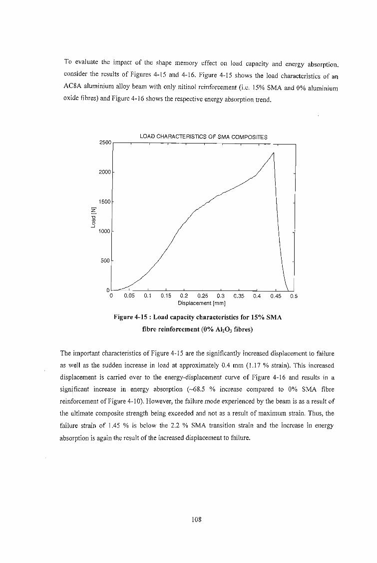
To evaluate the impact of the shape memory effect on load capacity and energy absorption,
consider the results of Figures 4-15 and 4-16. Figure 4-15 shows the load characteristics of an
AC8A aluminium alloy beam with only nitinol reinforcement (Le. 15% SMA and 0% aluminium
oxide fibres) and Figure 4-16 shows the respective energy absorption trend.
LOAD CHARACTERISTICS OF SMA COMPOSITES2500,--,----,----,---,---,----,---,----.-_--._---,
2000
1500
Z"'C<tlo
...J
1000
500
OL-=--'-----'----'--_---'-__l--_-'---_--'-_--'--_-.l_....L-Jo 0.05 0.1 0.15 0.2 0.25 0.3 0.35 0.4 0.45 0.5
Displacement [mm]
Figure 4-15 : Load capacity characteristics for 15% SMA
fibre reinforcement (0% Alz03 fibres)
The important characteristics of Figure 4-15 are the significantly increased displacement to failure
as well as the sudden increase in load at approximately 0.4 mm (1.17 % strain). This increased
displacement is carried over to the energy-displacement curve of Figure 4-16 and results in a
significant increase in energy absorption (-68.5 % increase compared to 0% SMA fibre
reinforcement of Figure 4-10). However, the failure mode experienced by the beam is as a result of
the ultimate composite strength being exceeded and not as a result of maximum strain. Thus, the
failure strain of 1.45 % is below the 2.2 % SMA transition strain and the increase in energy
absorption is again the result of the increased displacement to failure.
108

ENERGY CHARACTERISTICS OF SMA COMPOSITES0.7,-----.......--,----.----r--,-----.......---,----.----r----,
0.6
0.5
2:E;i0.4a;c:W
.~ 0.3
U5
0.2
0.1
Ol..-..-.......-===--..1---'------''----'----'---'----'----'o 0.05 0.1 0.15 0.2 0.25 0.3 0.35 0.4 0.45 0.5
Displacement [mm)
Figure 4-16 : Energy absorption characteristics for 15% SMA
fibre reinforcement (0% Ah03 fibres)
Figures 4-17 and 4-18 show the effect of prestrain on load capacity and energy absorption
respectively. The load capacity graph shows a decreasing load trend with increasing prestrain,
primarily because the prestrain imparts a preload to the beam, which causes the composite strength
to be reached at a lower applied load. The energy absorption capacity of Figure 4-18 shows an
initial increase of approximately 24 % before decreasing to 68 % of the initial value. The initial
increase in energy absorption is because the prestrain causes the 'plasticity-like' phase, just before
phase transition, to be reached sooner and the consequent decrease in energy absorption is as a
result of the prestrain load approaching the ultimate strength of the composite.
Thus, the phenomenon of increased energy absorption of Figure 4-16 highlights a critical point;
any energy capacity increase that is observed as a consequence of using smart SMA reinforcement
is not always attributable to the shape memory effect. This implies that careful design
consideration must be given to extract the maximum benefit of the smart reinforcement.
109

EFFECT OF PRE-STRAIN ON LOAD CAPACITY
2355
2350
..... 2345z....~ 2340o
...J 2335
2330
2325
o 0.002 0.004 0.006 0.008 0.01 0.012 0.014 0.016
Pre-Strain
Figure 4-17 : Effect of pre-strain on load capacity for 15% SMA
fibre reinforcement (0% AIz03 fibres)
EFFECT OF PRE-STRAIN ON ENERGY ABSORPTION
0.7
0.6
0.5.....2.>. 004El~ 0.3w
0.2
0.1
oo 0.002 0.004 0.006 0.008 0.01 0.012 0.014 0.016
Pre-Strain
Figure 4-18 : Effect of pre-strain on energy absorption capacity for 15% SMA
fibre reinforcement (0% Alz0 3 fibres)
110

In a final attempt to understand the contribution of phase transition to the energy absorption
capacity of a material, the failure criteria of ultimate composite strength is removed and the beam
is allowed to fail only by ultimate strain of the nitinol fibre. Figure 4-19 shows the resulting energy
absorption capacities for various degrees of prestrain.
ENERGY CHARACTERISTICS OF SMA COMPOSITES1.4 ,----,----,--,---,----,----,---,------,
1.2/ / / / /
6% 5%· 3% 2% 1%
/ /0% Prestrain
E;; 0.8CDcill
.~ 0.6
U5
0.4
0.2
0.1 0.2 0.3 0.4 0.5Displacement [mm]
0.6 0.7 0.8
Figure 4-19 : Effect of pre-strain on non-failure energy absorption capacity
through the shape memory effect of SMA
The phase transition effect of the SMA on energy absorption is clearly evident from the above
figure. Importantly, the maximum energy absorption capacity of the beam is not reached for the
applied impact conditions, i.e. the beam does not fail. Thus, for a non-failure condition, the effect
of prestrain is not to increase the energy absorbed by the material, but to increase the rate of energy
absorption, Le. the energy is absorbed through a smaller displacement. An increase of
approximately 96.5 % is observed when the energy absorption of Figure 4-19 is compared to the
maximum energy absorption of Figure 4-18. The maximum energy absorption capacity of the
beam is simulated to be 3.52 J, i.e. over 5 times the maximum energy absorption indicated in
Figure 4-18.
The effect of prestrain on the failure (maximum) energy absorption capacity of a SMA reinforced
metal matrix composite beam is to further increase the energy capacity up to a maximum of 11 .61 J
at 9 % prestrain as indicated in Figure 4-20.
III

EFFECT OF PRE-STRAIN ON ENERGYABSORPTION
14
12
.... 102>. 8Cl; 6s:::::
w 4
2
oo 0.05 0.1
Pre-Strain
0.15 0.2
Figure 4-20 : Effect of pre-strain on failure energy absorption capacity
through the shape memory effect of SMA
This is a 16.5 times increase over the maximum energy absorption of Figure 4-18 (SMA reinforced
beam with no phase transition effect) and a 36 times increase over the energy absorption of Figure
4-8 (Aluminium oxide reinforced beam). While the effect of SMA phase transition on energy
absorption is dramatic, the maximum stress in the beam at the maximum energy absorption (11.61
J) is 2510 MPa. Thus, in the design of a smart composite using SMA reinforcement for energy
absorption, the matrix material needs to be thoroughly assessed to facilitate maximum use of the
SMA phase transition effect.
In summary, the use of SMA fibres in a metal matrix composite can double the material's energy
absorption capacity when loaded to below the SMA martensitic phase transition strain and can
increase energy absorption levels by up to 36 times when full utilisation of the phase transition
effect is made. The material, however, needs to be designed such that the failure mode is by
ultimate fibre strain and not ultimate composite strength, for maximum benefit of the smart
reinforcement to be achieved.
112
CHAPTER 5
5 CONCLUSIONS
Smart materials have enormous potential in a wide variety of industries, however, due to a jack of
understanding, these materials are still considered too sophisticated to be used in ordinary day-to
day design applications. Thus, in a broader context, the aim of this thesis is to increase the
understanding of the behaviour of smart materials, and in so doing help to erase the perception that
these materials are beyond the reach of the vast majority of designers and engineers.
More specifically, the primary objective of this investigation is the determination of the ability of
smart materials (SMA, magnetostrictive materials and piezoelectric materials) to enhance the
performance of an ordinary metal-matrix composite beam in terms of load carrying capability and
energy absorption capacity. The second important objective is the increase in understanding and
competence for the author in peripheral activities such as numerical modelling and simulation
techniques, data interpretation and evaluation, as well as a broader understanding of material
behaviour in general.
Thus, the outputs of the study can be summarised as follows:
• The investigation of a magnetostrictive SMA hybrid composite with piezoelectric actuator,
smart material that is capable of enhancing load attenuation and energy absorption
characteristics.
• Fundamental understanding of the microstructural behaviour of SMA, magnetostrictive
materials, piezoelectric materials and smart composites in general.
• Fundamental understanding and competence development in numerical modelling and
simulation techniques, data interpretation and evaluation.
The methodology employed in this investigation is driven by two primary factors. The first is the
unique approach that the author puts forward to attempt to simplify the characterisation of damage
in not just metal matrix composites but in materials in general. The second factor is the lack of
available literature on smart material energy absorption as well as a lack of precise theory for short
fibre composites.
The characterisation of the energy absorption of a structural system is relatively simple in the
elastic region of the materials involved. This is as a result of well-defined, predictable material
113

behaviour and mature analytical models. However, once the realm of plasticity is entered, the
characterisation gets difficult due to complex theories surrounding various damage models. Having
a practical engineering background, the author finds these complex analytical descriptions
extremely frustrating and limiting to practical engineering predictions. Thus, in an attempt to
facilitate simple engineering models, the concept of a damage modulus is introduced. The
importance of the damage modulus is two fold. Firstly, it is a single factor that describes a material
through its entire strain range and secondly it takes into account 'damage' in material modelling
and thus simplifies analyses by a considerable amount.
ED is derived from the stress-strain curve for the specific materials and thus, warrants no additional
experimental investigation. The simplification in using this theory is that elastic analysis can now
be used through the plastic strain range as well. Further, damage is taken into account by
incorporating an effectively reducing Young's Modulus in the plastic zone.
The second factor driving the methodology of this investigation is the lack of available literature
on energy absorption of smart metal matrix composites. Thus, an extensive literature review is
conducted to facilitate familiarisation of relevant work as well as to develop a thorough
understanding of the behaviour of the various individual material types. The literature review thus
serves as a means of developing a broad understanding, physically, of various individual
components of the study, viz. microstructural behaviour of SMA, general impact loading
phenomenon, general behaviour of composite materials (interactive behaviour between elements),
as well as magnetostrictive and piezoelectric phenomenon.
As the core of the investigation, the author develops an analytical model, based on the damage
modulus concept, to predict the behaviour of a short fibre metal matrix composite during a Charpy
impact test. The model is verified using the experimental results given by Aggag et. al. A smart
composite Charpy test is then simulated by replacing the damage modulus characteristics of some
of the fibres with the damage modulus of SMA fibres. The results obtained are then compared to
those obtained by Aggag et al to quantify the effect of the SMA on impact energy absorption.
Finally, to simulate the effect of the magnetostrictive inclusions, the SMA model is subject to
varying degrees of pre-strain to represent the reaction of the magnetostrictive elements to varying
degrees of magnetic field.
The basic elastic stress / strength theory of the falling mass impact analysis highlights two
important considerations. The first is the geometric relationship between the two-dimensional
beam displacements during the impact process to the one-dimensional longitudinal strain of the
beam. This is very important as it facilitates the crossover from the load-displacement domain to
114

the stress-strain domain, thus enabling the point of plasticity to be correctly determined from the
material stress-strain curve. The second important consideration is the effect of the beam strain
energy on the velocity of the falling mass. The velocity-displacement profile that is derived is
based on the conservation of energy principle and demonstrates the integrity of the model in
describing a real system. The effect of air resistance on the energy balance of the system is ignored
and the effect of potential energy variation due to beam displacement is considered negligible.
The theoretical modelling is executed with numerical modelling using the MATLAB® software
package.
The results show that a 4% smart fibre volume fraction gives the beam an approximate 1.6%
increase in strain energy capacity. This, however, is not a direct result of the shape memory effect,
. but rather because of the higher toughness of the SMA fibres. Of the additional energy that is
absorbed, 0.002 J (0.6 %) is used toward the additional displacement and the balance of 0.005 J
(1.0 %) is consumed by the additional toughness of the SMA fibres.
The analysis of the effect' of varying SMA volume fradions show a definite trend of decreasing
load capacity with increasing SMA volume fraction, which the author attributes to the lower
strength of the nitinol fibres as compared to the aluminium oxide fibres.
An analysis of the effect of prestrain shows a similar trend in that there is an increase in energy
absorption levels up to a turning point of 6% SMA volume fraction, followed by a definite
decreasing energy absorption trend. The reason behind this 6% SMA volume fraction turning point
is a change in failure mechanism. Up to 6% SMA volume fraction the beam fails because its
ultimate strength is exceeded while SMA volume fractions in excess of 6% results in failure
because the ultimate strain of the Ah03 fibre is exceeded. Thus, as the SMA volume fraction is
increased, the load capacity of the beam decreases, but at the same time the displacement of the
beam for a particular load increases (because of the difference in Young's modulus ofthe fibres).
The effects of prestrain on load capacity and energy absorption for 6 % smart fibre reinforcement
(9 % aluminium oxide fibres) shows a relatively constant load capacity characteristic. The energy
absorption curve, on the other hand, peaks at a maximum increase of approximately 30% at 0.3%
prestrain, before decreasing to 35% of its original capacity. Again, this increase in energy
absorption trend is not because of the shape memory effect but due to the higher toughness of the
nitinol fibres and the following decrease in energy absorption capacity is as a result of the prestrain
approaching the ultimate strain of the Ah03 fibres.
115

The important characteristic of the analysis of 15 % smart fibre reinforcement (no aluminium oxide
fibres) is the significantly increased displacement to failure. This increased displacement is carried
over to the energy-displacement curve and results in a significant increase in energy absorption
(~68.5 % increase compared to 0% SMA fibre reinforcement). However, the failure mode
experienced by the beam is as a result of the ultimate composite strength being exceeded and not as
a result of maximum strain and the increase in energy absorption is again the result of the increased
displacement to failure.
The effect of prestrain on the 15 % smart fibre reinforced beam shows a decreasing load trend with
increasing prestrain, primarily because the prestrain imparts a preload to the beam, which causes
the composite strength to be reached at a lower applied load. The energy absorption capacity shows
an initial increase of approximately 24 % before decreasing to 68 % of the initial value. The initial
increase in energy absorption is because the prestrain causes the 'plasticity-like' phase, just before
phase transition, to be reached sooner and the consequent decrease in energy absorption is as a
result of the prestrain load approaching the ultimate strength of the composite.
Thus, the phenomenon of increased energy absorption described above highlights a critical point;
any energy capacity increase that is observed as a consequence of using smart SMA reinforcement
is not always attributable to the shape memory effect. This implies that careful design
consideration must be given to extract the maximum benefit of the smart reinforcement.
Finally, the effect of the phase transition phenomenon of shape memory alloys on the energy
absorption characteristics of the beam is investigated. For a non-failure condition, the effect of
prestrain is not to increase the energy absorbed by the material, but to increase the rate of energy
absorption. An increase of approximately 96.5 % is observed when the energy absorption is
compared to the maximum energy absorption of the smart beam with no phase transition. The
maximum energy absorption capacity of the beam is simulated to be 11.61 J, with prestrain effects,
resulting in a 36 times increase in energy absorption capacity over the aluminium oxide reinforced
beam.
Thus in summary, the use of SMA fibres in a metal matrix composite can double the material's
energy absorption capacity when loaded to below the SMA martensitic phase transition strain and
can increase energy absorption levels by up to 36 times when full utilisation of the phase transition
effect is made. The material, however, needs to be designed such that the failure mode is by
ultimate fibre strain and not ultimate composite strength, for maximum benefit of the smart
reinforcement to be achieved.
116

The thesis thus achieves its objective in investigating the ability of smart materials to enhance the
energy absorption characteristics of regular fibre reinforced metal-matrix composite materials
subject to low velocity impact loading. Of equal importance to the achievement of this objective is
the introduction in the thesis ofthe unique damage modulus that goes to the foundation of material
characterisation for mechanical engineering design and has profound implications in damage
theory and future design methodologies. Significant learning has taken place in the execution of
this PhD endeavour and this thesis will no doubt contribute to other investigations in the field of
smart materials.
In terms of future work in this field of study, this investigation opens up two critical avenues of
research. The first is a direct follow-on to the results presented in the current thesis and includes
experimental investigation of various SMA reinforcement materials as well as an investigation into
appropriate matrix substrates to complement the phase transition effect of SMA in energy
absorption. Further, a practical attempt needs to be made in using magnetostrictive inclusions and
piezoelectric sensors to control the onset of martensitic transformation in SMA. The second avenue
of research is the qualification of the damage modulus concept by experimental methods. The
author foresees numerous loading conditions being analytically modelled, for homogenous and
composite materials, using the damage modulus concept and then experimentally verified to
determine the extent to which this concept can be applied.
117

REFERENCES
Agbossou, A., Mahut, T. and Pastor, l., (1998), "Dynamic Analysis of Piezoelectric Fibre
Composite in an Active Beam Using Homogenisation and Finite Element Methods",
journal of Intelligent Material Systems and Structures, Vol.9, No.l2, p.1009-1016,
Technomic Publishing, United States of America.
Aggag, G. A., Han, K. S., Nam, H. W. and Takahashi, K., (1999), "The dynamic behaviour of
metal-matrix composites under low-velocity impact", Composites Science and Technology,
Vol. 60, p.817-823, Elsevier.
Alderson, K. L., Alderson, A. and Evans, K. E., (1997), "The Interpretation of the Strain
dependent Poisson's Ratio in Auxetic Polyethylene", Journal of Strain Analysis, Vo1.32,
p.201-212.
Anderson, T. A., Calvert, P. D., Denham, H. B. and Madenci, E., (1997), "Embedded PVF2
Sensors for Smart Composites", Proceedings of SPIE - The International Society for
Optical Engineering, Vol. 3040, p.138-147, Society of Photo-Optical Instrumentation
Engineers, United States of America.
Atherton, D. L. and liles, D. C., (1986), "Theory of Ferromagnetic Hysteresis ", Journal of
Magnetisation and Magnetic Materials, Vo1.61, p.48-60.
Bazant, Z. P. and lirasek, M., (2002), "Nonlocal Integral Formulations of Plasticity and Damage:
Survey of Progress", Journal ofEngineering Mechanics, p.1119-1149.
Belingardi, G., Gugliotta, A. and Vadori, R., (1998), "Fragmentation of Composite Material
Plates Submitted to Impact Loading: Comparison Between Numerical and Experimental
Results", Journal of Key Engineering Materials, Vo1.144, p.75-88, Politecnico di Torino,
Italy.
Birman, V., (1997), "Review of Mechanics of Shape Memory Alloy Structures ", Journal of
Applied Mechanics Review, Vo1.50, No.n, Pt. 1, p.629-645, ASME, United States of
America.
ll8
Birman, V., Chandrashekhara, K. and Sain, S., (1996a), "Approach to Optimisation of Shape
Memory Alloy Hybrid Composite Plates Subjected to Low Velocity Impact", Journal of
Composites, Part B : Engineering, Vo1.27B, p.439-446, Elsevier, United Kingdom.
Birman, V., Chandrashekhara, K. and Sain, S., (1996b), "Global Strength of Hybrid Shape
Memory Composite Plates Subjected to Low Velocity Impact", Journal of Reinforced
Plastics Composites, Vo1.16. p. 791-809.
Brinson, L. C., (1993), "One-dimensional Constitutive Behaviour of Shape Memory Alloys:
Thermomechanical Derivation with Non-constant Material Functions and Redefined
Martensite Internal Variable", Journal of Intelligent Material System Structures, VolA,
p.229-242.
Brinson, L. C. and Lammering, R., (1993), "Finite Element Analysis ofthe Behaviour of Shape
Memory Alloys and their Application", International Journal of Solids and Structures,
Vol. 30, p.3261-3280.
Casciati, F., Faravelli, L. and Petrini, L., (1998), "Energy Dissipation in Shape Memory Alloy
Devices", Journal ofComputer-Aided Civil and Infrastructure Engineering, Vol.13, No. 6,
pA33-442, University ofPavia, Italy.
Chandra, N. and Rajendran, A. M., (1998), "Micromechanics Based Modelling of Damage in
Composites Under High Velocity Impact - A Review", Proceedings of the 1998 5th
International Conference on Structures Under Shock and Impact, p.421-432,
Computational Mechanics Inc., United States of America.
Charles, J. L., Collombet, F., Jeronimidis, G., Lalbin, X. and Lataillade, J. L., (1997),
"Methodology and Tools for the Study of Composite Structures Under Impact Loading:
Application to Long Fibre Laminated Structures", Journal De Physique. IV, Vol.7, No. 3,
p.163-I68, Ecole Nationale Superieure d'Arts et Metiers, France.
Chattopadhyay, A. and Seeley, C. E., (1997), "A Higher Order Theory for Modelling Composite
Laminates with Induced Strain Actuators", Journal of Composites Pdrt B: Engineering,
Vo1.28, No. 3, p.243-252, Elsevier, England.
119

Chaudhry, Z., Kiesling, T. c., Paine,1. S. N. and Rogers, C. A., (1996), Proceedings ofthe 37th
AIAA I ASME I ASCE I AHS I ASC Structures, Structural Dynamics and Materials
Conference p. 1448, ASME, United States of America.
Collombet, F., Lalbin, X. and Lataillade, J. L., (1997), "Impact Behaviour of Laminated
Composites: Physical Basis for Finite Element Analysis", Journal of Composites Science
and Technology, Vo1.58, No.3-4, p.463-478, Lab Materiaux Endommagement Fiabilite
ENSAM, France.
Dapino, M. 1., Flatau, A. B. and Smith R. C., (1998), "An Active and Structural Strain Model
for Magnetostrictive Transducers", Journal ofProceedings ofthe SPIE - The International
Society for Optical Engineering, Vo1.3329, Pt. 1-2. p.198-209, SPIE - Int. Soc. Opt. Eng.,
United States of America.
Dang, X. and Liu, D., (1998), " Testing and Simulation of Laminated Composites Subjected to
Impact Loading", ASTM Special Technical Publication, No. 1330, p.273-284, ASTM,
United States of America.
Dharani, L. R. and Flocker, F. W., (1998), "Modelling Interply Debonding in Laminated
Architectural Glass Subject to Low Velocity Impact", Journal of Structural Engineering
Mechanics, Vo1.6, No. 5. p.485-496, Stress Engineering Services, United States of America.
ElIis, R. L., Jia, H., Lalande, F. and Rogers, C. A., (1997), Proceedings ofthe 38th AIAA I ASME
IASCE I AHS I ASC Structures, Structural Dynamics and Materials Conference, ASME,
United States of America.
Evans, K. E., Smith, C. W. and Wootton, R. J., (1999), "Interpretation of Experimental Data for
Poisson's Ratio of Highly Nonlinear Materials", Journal of Experimental Mechanics,
Vol. 39, No.4, p.356-362, Sage Publications Inc., United States of America.
Funakubo, H., (1987), "Shape Memory Alloys ", Gordon & Bleach, New York.
Furuya., Y., (1996), "Design and Material Evaluation of Shape Memory Composites", Journal
of Intelligent Material Systems and Structures, Vol. 7, p.321-330, Technomic Publishing,
United States of America.
120

Giannakopoulos, A. E., Ramamurty, U, Sridhar, S. and Suresh, S., (1999), "An Experimental
Study of Spherical Indentation on Piezoelectric Materials", Journal ACTA Materialia,
Vol.47, No. 8, p.2417-2430, Elsevier, England.
Hamouda, A. M. S. and Hashmi, M. S. J., (1998), "Testing of Composite Materials at High Rates
of Strain: Advances and Challenges", Journal ofMaterials Processing Technology, Vo!. 77,
No. 1-3, p.327-336, Dublin City University, United Kingdom.
Harding, J. and Ruiz, C., (1998), " Mechanical Behaviour of Composite Materials Under Impact
Loading", Journal ofKey Engineering Materials, Vol. 141-143, Pt. 2, p.403-426, University
of Oxford, United Kingdom.
Jiles, D. C., (1991), "Introduction to Magnetism and Magnetic Materials ", Chapman & Hall,
New York.
Joshi, S. P. and Mannas, J. R., (1993), "Study of Smart-Sensing Elements in a Dynamic Stress
Field", SPIE - The International Society for Optical Engineering, Vol.1918, p.264-275, .
SPIE - Int. Soc. for Opt. Engineering, United States of America.
Lewis, M. W., (1998), "On Predicting and Modelling Material Failure Under Impact Loading",
Proceedings of the 1998 5th International Conference on Structures Under Shock and
Impact, p.569-578, Computational Mechanics Inc., United States of America.
Li, S., Liang, C. and Rogers, C. A., (1991), "Active Damage Control of Hybrid Material Systems
using Induced Strain Actuators", Proceedings of the 32nd AIAAIASMEIASCEIAHSIASC
Structures, Structural Dynamics and Materials Conference, p.1l90-1203, AIAA, United
States of America.
Liang, C. and Rogers, C. A., (1990), "One-dimensional Thermomechanical Constitutive Relations
for Shape Memory Materials", Journal of Intelligent Material System Structures, VoU,
p.207-234.
Liang, C. and Rogers, C. A., (1991), "Multi-dimensional Constitutive Relations of Shape Memory
Alloys", Proceedings of the 32nd AIAAlASMElASCElAHSIASC Structures, Structural
Dynamics and Materials Conference, Part 1, p.178-185, AIAA, United States of America.
121

Livingston, J. D., (1982), "Magnetomechanical Properties of Amorphous Metals", Phys. Stat. Sol.
(aJ, Vo1.70, p.591.
Mines, R. A. W., (1998), "mpact Energy Absorption of Polymer Composite Sandwich Beams",
Journal of Key Engineering Materials, Vol. 141-143, Pt. 2, p.553-572, University of
Liverpool, United Kingdom.
Miyazaki, S., Sandstrom, R. and Wei, Z. G., (1998), "Shape-Memory Materials and Hybrid
Composites for Smart Systems. n. Shape-Memory Hybrid Composites", Journal of
Materials Science, Vol.33, No. 15, p.3763-3783, Royal Institute of Technology, United
Kingdom.
Nagaki, S. and Tanaka, K., (1982), "Thermomechanical Description of Materials with Internal
Variables in the Process of Phase Transformation", Ingenieur-Archiv, Vo1.51, p.287-299.
Needleman, A., (1997), "Numerical Modelling of Crack Growth Under Dynamic Loading
Conditions", Journal of Computational Mechanics, Vo1.l9, No. 6, p.463-469, Brown
University, United States of America.
Paine,1. S. N. and Rogers, C. A., (l994a), "Active Materials and Smart Structures", SPIE - The
International Society for Optical Engineering, Vol.2427, p.358, SPIE - Int. Soc. for Opt.
Engineering, United States of America.
Paine,1. S. N. and Rogers, C. A., (l994b), "Smart Structures and Materials 1994: Smart Structures
and Intelligent Syatems", SPIE - The International Society for Optical Engineering,
Vol.2190, pA02, SPIE - Int. Soc. for Opt. Engineering, United States of America.
Rao, S. S. and Sunar, M., (1999), "Recent Advances in Sensing and Control of Flexible Structures
via Piezoelectric Materials Technology", Journal ofApplied Mechanics Review, Vo1.52,
No. 1, p.I-16, ASME, United States of America.
Schulgasser, K., (1992), "Relationships between the Effective Properties of Transversely Isotropic
Piezoelectric Composites", Journal ofMechanics, Physics and Solids, Vo1.40, p.473-479.
Sittner, P., Takakura, M., Tokuda, M. and Ye, M., (1998), "Calculation of Mechanical Behaviours
of Shape Memory Alloy Under Multi-Axial Loading Conditions", International Journal of
Mechanical Sciences, Vol.40, No.2-3, p.227-235, Pergamon-Elsevier, England.
122

Tanaka, K., (1986), "A Thermomechanical Sketch of Shape Memory Effect: One Dimensional
Tensile Behaviour", Res Mechanica, Vo1.18, p.251-263.
Tanaka, K., (1990), "Phenomenological Description on Thennomechanical Behaviour of Shape
Memory Alloys", Journal ofPressure Vessel Technology, Vol.l12, p.158-163.
Tanaka, K., (1991), "Analysis of Recovery Stress and Cyclic Deformation in Shape Memory
Alloys", Advances in Continuum Mechanics, p.441-451 , Springer-Verlag, Berlin.
Taya, M., (1999), "Micromechanics Modelling of Smart Composites ", Journal ofComposites
Part A: Applied Science and Manufacturing, Vo1.30, No.4, p.531-536, Elsevier, United
Kingdom.
Ullakko, K, (1996), "Magnetically Controlled Shape Memory Alloys: A New Class ofActuator
Materials", Journal of Materials Engineering and Performance, Vo1.5, No.3, p.405-409,
ASM Int., United States of America.
Wang, B., (1992)," Three-dimensional Analysis of an Ellipsoid Inclusion in a Piezoelectric
Material", International Journal ofSolids Structures, Vol. 29, p.293-308.
Vu, N., (1995), "Micromechanical Modelling of Effective Electro-thermo-elastic Properties of
Two-phase Piezoelectric Composites", IUTAM Symposium on Microstructure - Property
Interactions in Composite Materials, p.397-405.
123

APPENDIX A
PRELIMINARY LITERATURE REVIEW AND SELECTED
BIBLIOGRAPHY
The objective of this appendix is to present the reader with the initial preliminary literature review
that was conducted to assist the author with choosing the topic for this PhD thesis. As a
consequence of this review, an extensive list of available literature on the subjects of impact
loading and smart materials was drawn up. This list is also presented in this appendix as a selected
bibliography. Note that all references quoted in the preliminary literature review can be found in
the selected bibliography.
Al. Preliminary Literature Review
In recent years, SMA has been given an increasing amount of attention and consideration to
engineering applications. This increasing popularity stems from their characteristic high damping
capacity, large recoverable strain and recovery stress and remarkable property changes due to
stress or thermal induced martensitic transformations. Further, Shape memory materials can be
easily fabricated into various forms such as fibres, wires, ribbons, particles and thin films and thus,
facilitate commercial viability.
While most early efforts in understanding the behaviour of embedded shape memory materials
concentrated on thermoplastics and thermosets, partly due to their technical simplicity in
manufacturing, recent engineering approaches have been extended to metal or silicon matrices
(Miyazaki, Sandstrom & Wei : 1998). The advantages of metal matrix shape memory alloys has
been cited by Miyazaki et. al. (1998) as their ability to achieve unique properties such as self
strengthening or self-relaxation and high damping capacity.
The unique properties of shape memory materials can essentially be ascribed to their ability to
transform between the austenite and martensite phase under specific shear stress or thermal
conditions. The transformation of austenite to martensite by the application of cooling results in no
significant deformation and the material microstructure reverts to the austenite phase upon
reheating. The critical temperatures in this process are the martensite start temperature (the
temperature at which the martensite transformation begins), martensite finish temperature (the
temperature to which the material needs to be cooled for the entire microstructure to complete the
transformation to martensite), austenite start temperature (the temperature to which the martensitic
124

microstructure needs to be heated to initiate the transformation to the austenitic phase) and
austenite finish temperature (the temperature that needs to be reached to ensure complete
transformation to the austenite phase). The transformation of austenite to martensite by the
application of shear stress results in significant deformation (compared to thermally induced
martensite) and will only revert to the austenitic phase upon unloading if the temperature is above
the austenite finish temperature (Sittner, Takakura & Tokuda : 1998). If the temperature is less
than the austenite start temperature, then the deformation will be kept as residual strain until heated
to the austenite finish temperature. This is referred to as the pseudoelastic behaviour of SMA
(Figure A-I).
Stress Loading
rr
Residual Strain
Unloading
Strain
Figure A-I: The pseudoelastic behaviour of shape memory alloys
(modified after Sittner et.at. : 1998)
Thus, the shape memory effect can be similarly depicted as (Figure A-2),
Stress
Heating
Strain
Figure A-2: The shape memory effect of shape memory alloys
(after Sittner et. at. : 1998)
125

The stress induced martensite transformation will only take place if the applied stress reaches the
critical transformation stress. However, martensite can still be obtained if the applied stress is
lower than the critical stress through the assistance of cooling (Figure A-3), i.e. cooling decreases
the critical stress threshold.
Stress Cooling
Heating
Strain
Figure A-3: The two-way shape memory effect of shape memory alloys
(after Sittner et. al. : 1998)
The primary objectives of Sitlner et. al. (1998) was the calculation of mechanical behaviours of
SMA under multi-axial loading conditions and the results of the investigation can be summarized
as follows,
• The shape memory alloy has a path dependent deformation behaviour.
• The zero stress state always corresponds to the zero strain state as in the elastic
deformation.
• Under non-proportional multi-axial loading, the original strain cannot be recovered, i.e. no
shape memory (possibly because some martensite variants produced in the previous
loading history disappears in the temperature cycle).
The most fundamental application of SMA is in material design to increase tensile strength.
Compressive residual stresses due to manufacturing processes is beneficial to mechanical
properties such as yield stress and fracture toughness and in composites arises from the generally
higher coefficient of thermal expansion of the filler to the matrix. The introduction of SMA to the
matrix can allow the filler (SMA) to shrink in the matrix at the operating temperature or with
increasing applied stress, thus producing compressive stress to contribute to the tensile properties
of the composite under load bearing conditions.
126

Miyazaki et. al. (1998) describes the design approach for the SMA fibre metal matrix composite as
follows (Figure A-4),
Preparation of theSIV1A composites
1Ivlemori si ng or otherheat treatment
1Cooli ng to lowertemperatures (MT)
I Prestraining the composites I
Heati ng to highertemperatures
Figure A-4: Design approach for SMA fibre metal matrix composites
(after Miyazaki et. al. : 1998)
This concept can be applied to a polymer matrix with SMA fibres and a metal matrix with SMA
particles composites as well. In general, the matrix compressive residual stress increases with
increasing fibre volume fraction and prestrain within a limited range and optimal prestrain and
fibre volume fractions can be found. Yield stress also increases with increasing temperature within
a limited temperature range. The enhancement of the resistance to fatigue crack propagation is
suggested to be ascribed to the combination of compressive residual stress, higher stiffness of the
composite, the stress induced martensitic transformation and the dispersion of mechanical strain
energy at the crack tip. Prestrain, on the other hand, generally contributes to the damage
accumulation for failure and decreases the elongation and ductility of the composite.
In determining the prestrain, elongation and ductility of a SMA composite it has to be realised that
Poisson's ratio is strictly defined only for small strain linear elastic behaviour. For highly nonlinear
elastic materials, such as smart materials, it becomes necessary to define a strain varying Poisson's
127

ratio. Consequently, Evans, Smith and Wootton (1999) have attempted interpretation of
experimental data for Poisson's ratio of highly nonlinear materials by defining various Poisson's
ratios based on various forms of strain. The usual strain quoted is the engineering strain
(sometimes called the nominal or Cauchy strain) and is a measure of extension relative to initial
length. When dealing with larger extensions it is common to refer to the true strain or Hencky
strain. Most textbooks define true strain as a summation of the ratio of extension to the
instantaneous length. The resulting integral returns the answer in logarithmic format and hence,
this true strain is sometimes referred to as the log true strain. Since the integral returns a secant
value of the extension and not a localised tangent value, it follows that if the deformation is
nonlinear, this true strain may not accurately reflect instantaneous conditions, but more those
relative to starting conditions. Thus, an instantaneous true strain is defined as the ratio between
extension and instantaneous length. This instantaneous strain is used to define the instantaneous
Poisson's ratio for greater accuracy in modeling the behaviour of highly nonlinear materials. The
instantaneous Poisson's ratio can be determined experimentally, graphically or numerically.
Evans et. al. (1999) goes on to describe various smoothing techniques that can be applied to a set
of experimental data to reduce the amount of noise. A summary of these techniques is presented
here,
• Polynomial regression can be performed automatically on many spreadsheet packages.
however, it is sometimes best to consider fitting several regressions to separate portions of
the data set rather than as a whole to avoid smothering localised effects.
• Moving average or weighted average techniques use a fixed number of data within a frame
that is moved along the entire data set. An arithmetic mean or weighted mean is calculated
for each step along the data set. The number of data included in the moving frame is
important, since this number controls the smoothing effect; the greater the number of
points, the greater the smoothing effect. However, the larger the number of data in the
moving frame, the more localised effects are blurred out and the more data are lost at the
start and finish of the data set. This method is not good with very noisy data.
• The Fourier transform method is more complicated to use than the other methods, but is
much more powerful. It overcomes the limitations of the frame size or statistical reliability
of a polynomial fit to a small data set, no data are lost at the start and end of the set, it is
possible to see clearly what information is being discarded (as noise) and what is kept and
it is easy to change the amount of information being discarded. The method works by
128

transforming the original data set into its frequency spectrum where it is possible to discern
the higher frequency noise component. The frequencies to be retained and discarded are
chosen. The data retained can then be transformed back from the frequency domain to its
original domain.
While the design approach presented in Figure A-4 appears straight forward, the first step tends to
prove difficult to implement. Miyazaki et. al. (1998) was initially unsuccessful in embedding Ti-Ni
directly into a polymer matrix due to manufacturing difficulties and problems associated with
interfacial bonding. The interfacial bonding issue was eventually overcome by alternatively
incorporating SMA wires into the polymer matrix using coupling sleeves. In general, fibre
reinforced thermoplastics offer substantial advantages over fibre reinforced thermosets because of
their excellent specific stiffness, high fracture toughness, low moisture absorption and possible fast
and cost effective manufacturing processes. Thermoplastics, however, require high processing
temperatures that affect the microstructure of the SMA; the transformation temperature of the
SMA shifts upwards while the peak recovery stress drops. The lower processing temperatures of
thermosets only mildly affect the transformation characteristics of SMA, though some dynamic
properties of the SMA fibres may be significantly affected (Miyazaki et. al. : 1998).
Furuya and colleagues (Furuya, Sasaki & Taya : 1993; Furuya, Mori, Shibata, Taya, Watanabe &
Yamada: 1993) have developed three kinds of fabrication procedures.
• The Ti-Ni fibres were arranged in a fixed holder in a mould, then molten aluminium
(970K) was poured into the mould followed by pressurisation at sixty-five megapascals.
Because the melting temperature of aluminium is not very high, even though a thin layer
with a thickness of less than three micrometers of the fibre surface was affected by
diffusion interaction, most of the Ti-Ni fibres remained unaffected during the processing.
The composite was then subjected to heat treatment (773 K, thirty minutes) to shape
memorise the Ti-Ni fibres, followed by ice water quenching to induce martensitic
transformation. A specific tensile prestrain was applied and then the composite was heated
to a temperature above the austenite finish point.
• Aluminium powders and Ti-Ni fibres were placed into a mould and pressed at two
hundred megapascals in air at room temperature to form a green sheet and then it was
sintered in a vacuum furnace (10-4 torr) at 843 K for one hour. A shape memory treatment
was simultaneously made during the sintering process. The porosity of the as-sintered
composite was eight percent. The high elongation of the aluminium matrix at room
temperature (up to twelve percent) was used to provide prestrains of up to four to five
129

percent to the Ti-Ni fibres. Pure aluminium, AI-I 100, has a very low yield stress and
hence, 6061-T6 and 6082-T6 aged aluminium alloys have been more recently used for
structural applications.
• Ti-Ni fibres were wound around or longitudinally laced onto thin aluminium alloy sheets
with rectangular end notches. The fibre laced prepreg sheets were stacked on a pair of hot
press dies or loaded into a vacuum canister and were then hot pressed at proper
temperatures and pressures. A thin layer (within three micrometers) of interfacial phases
such as AhTi and AhNi was produced because of the interfacial reactions between the Ti
Ni fibre and the matrix. The optimum hot pressing conditions for AI-6061 were found to
be 773 K for thirty minutes at fifty-four megapascals. The material could be either directly
water quenched and then aged, or cooled down in the furnace while keeping the pressure
constant, followed by a solution treatment and T6 ageing. A loading and unloading process
was applied to the composite at room temperature to produce various prestrains. The
processing procedure resulted in good macro scale homogeneity and little internal porosity,
and various volume fractions of Ti-Ni fibres could be embedded into the aluminium
matrix.
More recently, within the last three to four years, smart composites have been manufactured by
sheath rolling; the fibres were laminated between plates of the matrix material and then inserted
into a stainless steel pipe and vacuum encapsulated. The sealed laminates were then sheath rolled
at various temperatures and then reheated at the temperatures for different times. A thirty
micrometer reaction interfacial layer was formed between the fibres and the matrix and was found
to be effective for stress conductivity.
Upon completion of the composite manufacture, the embedded SMA fibres can be actively
controlled by electric current heating and hence undergo the reverse martensitic transformation,
giving rise to a change of stiffness, vibration frequency and amplitude, acoustic transmission or
shape of the composite. Active property control can be accomplished through a) the change in
stiffness (inherent modulus) of the embedded SMA elements or b) activating the pre-strained SMA
elements to generate a stress. These two techniques are termed active property tuning (APT) and
active strain energy tuning (ASET) respectively. Generally, APT requires a large volume fraction
of SMA fibres that are embedded without prior plastic elongation and do not create any large
internal forces. ASET, however, may be equally effective with an order of magnitude smaller
volume fraction of SMA fibres that are 'active' and impart large internal stresses throughout the
structure (Miyazaki et. al. : 1998). When fibres are activated by passing a current through them,
they will try to contract to their normal length, and therefore generate a large, uniformly distributed
130

shear load along the length of the fibres. High strain SMA fibres have a relatively high ultimate
strength and can absorb and dissipate a large amount of strain energy, first through the stress
induced martensitic transformation and then through plastic yielding. These SMA composites are
thus, ideally suited for impact damage control as compared to advanced composites such as
graphite/epoxy and glass/epoxy that have poor resistance to impact damage because of the lack of
an effective mechanism for dissipating impact strain energy.
SMA dissipates strain energy of the order of four times of high alloy steel and sixteen times that of
many graphite/epoxy composites through the stress induced martensitic transformations (Miyazaki
et. al. : 1998). This strain energy absorbing capacity can be used to actively control the propagation
of cracks. Paine and colleagues (paine & Rogers : 1994a; Paine & Rogers : 1994b; Chaudhry,
Kiesling, Paine & Rogers : 1996) made recent studies to improve the impact damage resistance of
brittle thermoset matrix composite materials by hybridising the composites with SMA. The low
velocity impact test was performed using an instrumented drop weight impact tester; the dissipated
impact energy and deflection, during impact were determined from force-time data. The results
showed that the composite with SMA fibres resisted the cutting action through distributing the
impact load over a greater surface area, because the SMA remained intact during the perforation
event. The monolithic graphite/epoxy and glass/epoxy and the aluminium and Kevlar hybrids all
failed locally from a punched or cut hole from the local transverse shear stresses at the edge of the
impact site. Further testing of composites (graphitelbismaleimide) embedded with SMA fibres
revealed greatly improved impact resistance due to an increase in peak impact force and a
reduction of the impacted induced delamination area. Testing with a reduced volume fraction of
SMA fibres, however, resulted in an increased delamination area as compared to plain
graphite/epoxy composites, though absorption of impact energy was increased. A quasi-static
model demonstrates that contact deformation, global bending deformation and transverse shear
deformation are the energy absorption mechanisms for SMA graphite/epoxy composites under a
low velocity impact (Pain et. al. : 1994a; Paine et. al. : 1994b; Chaudhry et. al. : 1996). At very low
velocities, the contact energy absorption is the most effective mechanism, while the shear
deformation absorbs most of the impact energy at higher impact velocities. The total energy
absorption of the SMA hybrid composites increases when the stress induced martensitic
transformation occurs.
The ballistic impact resistance of graphite composites was investigated by Ellis, Jia, Lalande and
Rogers (1997) using a nine-millimeter Beretta handgun with the projectile velocity greater than
nine hundred feet per second (274.32 m1s). The results suggest that the high strain absorption
capabilities of the SMA were not fully utilised at ballistic velocities because of the high strain rate
.effects coupled with a strain mismatch between the relatively tough SMA fibres and the brittle
131

cured epoxy resin. The SMA fibres were found to be more effectively used when embedded
between layers of the thermoplastic extended chain polyethylene (ECPE or Spectra) prepregs.
Though the energy absorption was increased when compared to the plain graphite composite, the
SMA fibres were still not fully utilised as evidenced by the lack of fibres strained to failure.
An ideal actuation material would display a large stroke, high recovery force and superior dynamic
response (Miyazaki et. al. : 1998). SMA exhibit large strokes and forces, but suffer from a slow
response. Ferroelectric ceramics are very sensitive to applied stresses through the direct
piezoelectric effect and generate powerful forces by means of the converse piezoelectric effect.
The ceramics are characterised by excellent dynamic response (of the order of microseconds) but
their displacements are quite small (of the order of a few micrometers) due to their small strain
magnitude. Piezoelectric thin films can be fabricated with various techniques such as sputtering,
chemical vapour deposition (CVD) and sol-gel processing. Blaszkiewicz, Chen, Meyer, Newnham
and Xu (1992) first successfully deposited thin films of PZT and PLZT, 0.6 and 1.4 nm in
thickness respectively on Ti-Ni SMA foils by the sol-gel process and multi-step spin-on coating
techniques. The PZT films were found to adhere well to the Ti-Ni alloy for strains as large as 0.4%
and their ferroelectric properties remained unchanged during repeated cycling through the shape
memory transformation. It is very important that the fabrication steps be minimised and if
deposited on amorphous SMA films, both types of the amorphous thin films be crystallized
simultaneously, so as not to promote degradation of performance due to second phases and
chemical interactions via diffusion. Although the hetrostructures have good piezoelectric
properties, the cracking ofthe piezoceramic thin film layer remains a crucial problem.
By coupling Ti-Ni SMA to PZT via a Ti02 buffer layer, the final composite material can sense and
actuate to dampen structural vibration without the use of external control as depicted in Figure A-5
(Miyazaki et. al. : 1998).
132

StressWave
... + + + +•••••• "t' .,. "t' T
......... + + + +
..... - ..... + + + +/LT'-T'..Jl<.:-:-:«.> + + + + ++ + ThX}-{)-Q-!
:.:....:-:-::+ + ... + +++~~}<J~.. . + .1-
+ + + +-: + + + + "LMJ""L_r"L)"'-J1. + + + +.:+ + ++ + ++ +i{:;R:}{P~
.... + + + +/r_r...J'-I' .. ..... + + + +
++++++++~Ri~~.... + + + +
+ + + +.....:::+ + + ++ + + +
~ Ti-Ni
~ PZT
o Ti02
I::::1 Buffer
Figure A-5: Self-sensing and actuation of a SMA PZT smart material
(after Miyazaki et. aI. : 1998)
The stress wave propagates through the Ti-Ni SMA producing a stress induced martensitic
transformation where some of the mechanical energy is converted into heat. The wave further
produces a voltage across the first ferroelectric layer that can be used to produce an out-of-phase
stress wave by the second ferroelectric layer, and in turn attenuate the stress wave. A mechanical
metallic impedance buffer (such as aluminium, titanium or Ti-Ni) is used to provide time for the
counter-stress attenuation to occur.
As compared to ferroelectrics, magnetostrictive materials provide large displacements, higher
counter forces and output energy density and superior manufacturing capabilities. Terfenol-D, for
example, can be fabricated with the conventional magnetron sputtering techniques. Amorphous
films show a sharp increase in the magnetostriction at low magnetic fields and no hysteresis during
cycling of the field, whereas the crystalline films exhibit magnetostrictive hysteresis loops and
large remanence and coercivity which limit their application (Miyazaki et. at. : 1998). Because
amorphous Terfenol-D films do not involve annealing at elevated temperatures, which may address
undesirable chemical interactions or diffusion, the fabrication of hybrid composite films seem
easier and simpler. Magnetostrictive materials application, however, has been limited by poor
fracture toughness, eddy current losses at higher frequencies and bias and prestress requirements.
I "",),)

A2. Selected Bibliography of Impact Loading and Smart Materials
Impact Loading
Alien, D. H. and Searcy, C. R., (1998), "Prediction of Damage Evolution in Laminated Composites
Subjected to Impact Loading", Journal of Mechanical Behaviour ofAdvanced Materials
American Society of Mechanical Engineers, Vo!.84, p.229-230, ASME, United States of
America.
Altay, B. and Doyum, A. B., (1997), "Low - Velocity Impact Damage in Glass Fibre/Epoxy
Cylindrical Tubes", Journal ofMaterials and Design, Vol. 18, No.3, p. 131-135, Middle
East Technical University, Turkey.
Anderson, T. A., Calvert, P. D., Denham, H. B. and Madenci, E., (1997), "Embedded PVF2
Sensors for Smart Composites", Proceedings of SPIE- The International Society for
Optical Engineering, Vo 1.3040, p. 138-1 '47, Society of Photo-Optical Instrumentation
Engineers, United States of America.
Andrades, L. and Benitez, F. G., (1997), "In-Plane Impact Loading of Composites: Optical
Evaluation and Crack Severity Assessment for Graphite-Epoxy", Journal De Physique. IV,
Vo!.7, No.3,p. 169-174, University of Seville, Spain.
Aschenbrenner, R. 1., Grace, C., Kelkar, A. D., Sankar, 1. and Schoeppner, G., (1997), "Behaviour
of Tensile Preloaded Composites Subjected to Low-Velocity Impact Loads", Recent
advances in Solids/Structures and Applications ofMetallic Materials American Society of
Mechanical Engineers, Pressure Vessels and Piping Division, Vo!. 369, p. 39-46, ASME,
United States of America.
Bank, L. C. and Gentry, T. R., (1998), " Finite-Element Modeling and Model Verification of Steel
W-Beam Guardrails Subject to Pendulum Impact Loading", Journal of Transportation
Research Record, No. 1647, p. 147-157, Georgia Institute of Technology, United States of
America.
Banthia, N., Gupta, P. and Van, C., (1999), "Impact Resistance of Fibre Reinforced Wet-Mix
Shotcrete - Part I: Beam Tests", Journal of Materials and Structures, VoU2, No. 222,
p.563-570. University of British Columbia, Canada.
134
Belingardi, G., Gugliotta, A. and Vadori, R., (1998), "Fragmentation of Composite Material Plates
Submitted to Impact Loading: Comparison Between Numerical and Experimental Results",
Journal ofKey Engineering Materials, Vo!. 144, p. 75-88, Politecnico di Torino, Italy.
Benzeggagh, M.1. and Chotard, T. J., (1998), "On the Mechanical Behaviour of Pultruded
Sections Submitted to Low-Velocity Impact", Journal of Composites Science and
Technology, Vol.58, No. 6, p.839-854, Universite de Technologie de Compiegne, France.
Beppu, M. and Miyamoto, A., (1998), "3-D Dynamic Analysis and Computer Graphics
Application to Impact Failure Simulation for Reinforced Concrete Slabs", Proceedings of
the 1998 5th International Conference on Structures Under Shock and Impact, p. 727-741,
Computational Mechanics Inc., United States of America.
Berstad, T., Hopperstad, O. S. and Langseth, M., (1999), "Impact Loading of Plates: Validation of
Numerical Simulations by Testing", International Journal of Offshore and Polar
Engineering, Vo!.9, No. 1, p. 10-15, Norwegian University of Science and Technology,
Norway.
Boniface, 1., Foreman, A. and Hitchen, S., (1998), "Comparative Evaluation of Solid and Hollow
S2 Glass Fibre-Epoxy Laminates", Journal ofPlastics, Rubber and Composites Processing
and Applications, Vol.27, No. 5, p.234-239. University of Surrey, United Kingdom.
Bonini, J., Collombet, F., Lalbin, X., LataiIlade, J. 1. and Martin, V., (1998), " Damage Criteria for
the Study of Impacted Composite Laminates", Journal of Composites Science and
Technology, Vo1.58, No.S, p.679-686. Esplanade des Arts el Metiers, France.
Caulfield, D. F., Clemons, C. M. and Giacomin, A. J., (1999), "Dynamic Fracture Toughness of
Cellulose-Fibre-Reinforced Polypropylene: Preliminary Investigation of Microstructural
Effects", Journal of Elastomers and Plastics, Vol.3l, No. 4, p.367-378, USDA Forest
Service, United States of America.
Chandra, N. and Rajendran, A. M., (1998), "Micromechanics Based Modeling of Damage in
Composites Under High Velocity Impact - A Review", Proceedings of the 1998 Sth
International Conference on Structures Under Shock and Impact, p.42I -432,
Computational Mechanics Inc., United States of America.
135

Charles, 1. L., Collombet, F., Jeronimidis, G., Lalbin, X. and Lataillade, J. L., (1997),
"Methodology and Tools for the Study of Composite Structures Under Impact Loading:
Application to Long Fibre Laminated Structures", Journal De Physique. IV, Vo!. 7, No. 3,
p. 163-168, Ecole Nationale Superieure d'Arts et Metiers, France.
Christoforou, A. P. and Yigit, A. S., (1998), "Effect of Flexibility on Low Velocity Impact
Response", Journal ofSound and Vibration, VoU17, No. 3, p.563-578, Kuwait University,
Kuwait.
Collombet, F., Lalbin, X. and Lataillade, 1. L., (1997), "Impact Behaviour of Laminated
Composites: Physical Basis for Finite Element Analysis", Journal of Composites Science
and Technology, Vo!.58, No.3-4, p.463-478. Lab Materiaux Endommagement Fiabilite
ENSAM, France.
Czigany, T., Karger-Kocsis, 1. and Moskala, E. 1., (1999), "Stress Oscillation in Amorphous
Copolyesters Due to Tensile Impact", Journal of Polymer Engineering and Science,
Vol.39, No.8, p. 1404-1411, Universitaet Kaiserslautern, Germany.
Dang, X. and Liu, D., (1998), "Testing and Simulation of Laminated Composites Subjected to
Impact Loading", ASTM Special Technical Publication, No. 1330, p.273 -284, ASTM,
United States of America.
Dang, X., Liu, D. and Raju, B., (1998), "Size Effects on Impact Response of Composite
Laminates", International Journal of Impact Engineering, VoU1, No. 10, p.837-854,
Michigan State University, United States of America.
Daves, T., Neogi, D. and Tessier, N. J., (1997), "Energy Absorbing Characteristics of Novel
Composite Materials", Structures Under Extreme Loading Conditions American Society of
Mechanical Engineers, Pressure Vessels and Piping Division, Vo1.351, p.325-340, ASME,
United States of America.
De Freitas, M. and Reis, L., (1997), "Damage Growth Analysis of Low Velocity Impacted
Composite Panels", Journal ofComposite Structures, Vo1.38, No. 1-4, p-509-515. Institute
of Superior Technico, Portugal.
136

Dharani, L. R. and Flocker, F. W., (1998), "Modeling Interply Debonding in Laminated
Architectural Glass Subject to Low Velocity Impact", Journal of Structural Engineering
Mechanics, Vo!. 6, No. 5, p.485-496. Stress Engineering Services, United States of America.
Dodds, R. H. and Koppenhoefer, K. C., (1997), "Loading Rate Effects on Cleavage Fracture of
Pre-Cracked CVN Specimens: 3-D Stadies" Journal ofEngineering Fracture Mechanics,
Vo1.58, No.3, p.249-270. University of Illinois, United States of America.
Dodds, R. H. and Koppenhoefer, K. C., (1999), "Numerical Investigation of Loading Rate Effects
in Pre-Cracked CVN Specimens", ASTM Special Technical Publication, No. 1332, p. 135
153, ASTM, United States of America.
Donze, F. V. and Magnier, S. A., (1998), "Numerical Simulations ofImpacts Using a Discrete
Element Method", Journal of Mechanics of Cohesive-Frictional Materials, Vol. 3, No. 3,
p.257-276, Universite du Quebec a Montreal, Canada.
Erki, M. A. and Meier, U., (1999), "Impact Loading of Concrete Beams Externally Strengthened
with CFRP Laminates", Journal of Composites for Construction, Vol.3, No.3, p.I17-124,
Royal Military Coil. of Canada, Canada.
Evans, K E., Jones, N. and Roach, A. M., (1998), "Penetration Energy of Sandwich Panel
Elements Under Static and Dynamic Loading. Part I", Journal of Composite Structures,
Vo!.42, No.2, p.119-134, Elsevier, United Kingdom.
Friedrich, K, Karger-Kocsis,1., Keith, S. and Yuan, Q., (1997), "Crash and Energy Absorption
Behaviour of Interleaved Carbon-Fibre-Reinforced Epoxy Tubes", Journal of Material
Science Letters, Vo1.l6, No. 22, p.1793-1796. Royal Institute of Technology, United
Kingdom.
Gary, G. and Zhao, H., (1997), "Experimental Investigation ofCompressive Failure Strength of
Fibre-Reinforced Polymer-Matrix Composite Plates Under Impact Loading", Journal of
Composites Science and Technology, Vo1.57, No. 3, p.287-292, Ecole Polytechnique,
France.
Hamouda, A. M. S. and Hashmi, M. S. 1., (1998), "Testing of Composite Materials at High Rates
of Strain: Advances and Challenges", Journal ofMaterials Processing Technology, Vo!. 77,
No. 1-3, p.327-336, Dublin City University, United Kingdom.
137

Harding, J. and Ruiz, c., (1998), "Mechanical Behaviour of Composite Materials Under Impact
Loading", Journal of Key Engineering Materials, Vo!. 141-143, Pt. 2, p.403-426.
University of Oxford, United Kingdom.
Hiramatsu, M., Takeda, N., Wan, L. and Yuan,1., (1997), "Characterisation of Effects of Strain
Rate and Temperature on Impact Compressive Damage Progress of Glass Fibre Reinforced
Composites", Journal ofTransactions ofthe Japan Society ofMechanical Engineers, Part
A, Vo!.63, No. 616, p.2598-2603, Japan Society of Mechanical Engineers, Japan.
Hojo, M., Kurokawa, T., Kusaka, T. and Ochiai, S., (1997), "Finite Element Simulation of Impact
End Notched Flexure Test Using Ramped Incident Waves (Verification of the Proposed
Method for Estimating Energy Release Rate)", Transactions of the Japan Society of
Mechanical Engineers, Part A, Vo!.63, No.605, p. 158-164, Japan Society of Mechanical
Engineers, Japan.
Hojo, M., Kurokawa, T., Kusaka, T. and Ochiai, S., (1998), "Evaluation of Mode H Interlaminar
Fracture Toughness of Composite Laminates Under Impact Loading", Journal of Key
Engineering Materials, Vo!. 141-143, Pt. 2, p-477-498, Hyogo Prefectural Institute of
Industrial Research, Japan.
Inou, N., Kuroda, H., Ujihashi, S. and Yamanaka, T., (1997), "Energy-Absorption Abilities of
CFRP Cylinders During Impact Crushing", Journal of Thin-Walled Structures, Vol. 28,
No. 3-4, p.297-307, Tokyo Institute of Technology, Japan.
Jang, l., Kim, H., Park, 1., Park, R. and Yun, Y., (1997), "Failure of Ceramic/Fibre-Reinforced
Plastic Composites Under Hypervelocity Impact Loading", Journal of Materials Science
Vol.32, No. 1, p.23-33. Royal Institute of Technology, United Kingdom.
Kelkar, A. D., Rajeev, K. and Sankar, J., (1998), "Analysis of Tensile Preloaded Composites
Subjected to Low-Velocity Impact Loads", Proceedings of the 1998 39th
AIAA IASMEI
ASCElAHSIASC Structures, Structural Dynamics and Materials Conference and Exhibit
and AIAA IASMFJAHS Adaptive Structures Forum. Part 3, Vol.3, p. 1978-1987, AIAA,
United States of America.
Kishore and Venkatraman, S., (1997), "Role of the Interface in Foam-Bearing Glass-Epoxy
Composites Subjected to Impact Loading", Journal of Composite Interfaces, Vo!.5, No. 1,
p. 55-67, Indian Institute of Science, India.
138

Kobayashi, Y., Morita, R., Nagasaka, 1., Ohnishi, N. and Yamaguchi, T., (1999), "Toughness
Evaluation Method Using Strength and Impulse of a Material Under Tensile Impact
Loading", Journal of the Japan Institute of Metals, Vol. 63, No. 4, p.502-507, Chubu
University, Japan.
Krasowsky, A. J. and Orynyak, 1. V., (1998), "Modeling of Elastic Response ofa Three-Point
Bend Specimen Under Impact Loading", Journal of Engineering Fracture Mechanics,
Vol. 60, No.5, p.563-575. National Academy of Sciences of Ukraine, Ukraine.
Kwon, Y. W. and Wojcik, G. W., (1998), "Impact Study of Sandwich Composite Structures with
Delamination", Journal of Composite Materials, Vol. 32, No. 5, p.406-430. Naval
Postgraduate School, United States of America.
Lewis, M. W., (1998), "On Predicting and Modeling Material Failure Under Impact Loading",
Proceedings of the 1998 5th International Conference on Structures Under Shock and
Impact, p.569-578. Computational Mechanics Inc., United States of America.
Mines, R. A. W., (1998), "Impact Energy Absorption of Polymer Composite Sandwich Beams",
Journal of Key Engineering Materials, Vol-141-143, Pt. 2, p.553-572. University of
Liverpool, United Kingdom.
Miyazaki, N., Satoh, M. and Sutoh, M., (1999), "Experimental Evaluation of Impact Damage in
FRP Laminates", Journal of the Society of Material Science, Vo1.48, No. 5, p.507-511,
Kyushu University, Japan.
Morozov, Y. A., Popov, G. Y. and Usov, A. V., (1999), "On the Tangential Stress Intensity Factor
for Semi-Infinite Cylindrical Crack Edge Under Impact Loading of the Crack Borders",
Journal of Problemy Prochnosti, No. 3, p.63-72, Odesskij Gosudarstvennyj University,
Ukraine.
Needleman, A., (1997), "Numerical Modeling of Crack Growth Under Dynamic Loading
Conditions", Journal of Computational Mechanics, Vol. 19, No. 6, p.463-469. Brown
University, United States ofAmerica.
Shapochkin, E. V. and Shapochkina, V. A., (1997), "Total Plastic Strain Under Local Impact
Loading", Journal of Fizika I Khimiya Obrabotki Materialov, No. 1, p. 104-108,
Moskovskaya Gosudarstvennaya Akademiya Priborostroeniya I Informatiki, Russia.
139.

Shioya, T., Takeda, N. and Yuan, J., (1999), "High Temperature Impact Response of Silicon
Nitride Ceramics", Journal ofKey Engineering Materials, Vo!. 166, p. 19-24, University of
Tokyo, Japan.
Tai, N-H., Tseng, C-M. and Yip, M-C., (1999), "Influences of Thermal Cycling and Low-Energy
Impact on the Fatigue Behaviour of Carbon/PEEK Laminates", Journal of Composites
Part B: Engineering, Vol. 30, No. 8, p.B49-865, Elsevier, United Kingdom.
Takeda, N. and Wan, L., (1995), "Impact Compression Damage Evolution in Unidirectional Glass
Fibre Reinforced Polymer Composites", High Strain Rate Effects on Polymer, Metal and
Ceramic Matrix Composites and Other Advanced Materials American Society of
Mechanical Engineers, Aerospace Division, Vo!.48, p. 109-113, ASME, United States of
America.
Wierzbicki, T., (1999), "Petalling of Plates Under Explosive and Impact Loading", International
Journal of Impact Engineering, Vo!.22, No. 9, p.935-954, Massachusetts Institute of
Technology, United States of America.
Woldesenbet, E., (1999), "High Strain Rates Properties of Composite Materials", Proceedings of
the 1999 ASME Energy Sources Technology Conference, ASME, United States of
America.
Zukas, 1. A., (1995), "Numerical Modeling of High Velocity Impact in Non-Metallic Materials",
High Strain Rate Effects on Polymer, Metal and Ceramic Matrix Composites and Other
Advanced Materials American Society of Mechanical Engineers, Aerospace Division,
Vol.48, p.49-62, ASME, United States of America.
Smart Materials - General
Adeli, H. and Saleh, A., (1998), "Integrated Structural/Control Optimisation of Large Adaptive /
Smart Structures", International Journal of Solids and Structures, Vol. 35, No. 28-29,
p.3815-3830, Elsevier, England.
Agnes, G. S. and Mall, S., (1999), " Structural Integrity Issues During Piezoelectric Vibration
Suppression of Composite Structures", Journal of Composites Part B: Engineering,
Vol.30, No. 7,p. 727-738, Elsevier, England.
140
Aizawa, S., Higasino, M. and Kakizawa, T., (1998), "Case Studies of Smart Materials for Civil
Structures", Journal of Smart Materials and Structures, Vol. 7, No. 5, p.617-626, lOP
Publishing, United Kingdom.
Austin, F., Clifford, R. and Van Nostrand, W., (1997), "Some Applications of Smart Materials in
Industry", Proceedings of US-Japan Workshop on Smart Materials and Structures,
Minerals, Metals and Materials Society / AIME, United States of America.
Banks, H. T. and Kurdila, A. J., (1996), "Hysteretic Control Influence Operators Representing
Smart Material Actuators: Identification and Approximation", Proceedings of the IEEE
Conference on Decision and Control, Vol.4, p.3711-3716, IEEE, United States of America.
Baz, A., Oh, J. and Ruzzene, M., (1999), "Control of the Dynamic Characteristics of Passive
Magnetic Composites", Journal of Composites Part B: Engineering, Vol.30B, p.739-751,
Elsevier, United Kingdom.
Berman, J. and White, S., (1996), "Theoretical Modeling of Residual and Transformational
Stresses in SMA Composites", Journal of Smart Materials and Structures, Vol.5, No. 6,
p. 731-743, lOP Publishing, United Kingdom.
Birman, V., (1996), "Thermal Effects of Measurements of Dynamic Processes in Composite
Structures Using Piezoelectric Sensors", Journal afSmart Materials and Structures, Vol.5,
No.4, p.379-385, lOP Publishing, United Kingdom.
Birman, V., (1997), "Review of Mechanics of Shape Memory Alloy Structures ", Journal of
Applied Mechanics Review, Vol.50, No.ll, Pt 1, p.629-645, ASME, United States of
America.
Blaszkiewicz, M., Chen, 1., Meyer, R, Newnham, R. E. and Xu, Q. C., (1992), Journal of
American Ceramic Society, Vol. 75, p.2891. United States of America.
Canon, E. and Lenczner, M., (1998), "Models of Thin Plates with Piezoelectric Inclusions and
Electronic Circuits", Journal of Comptes Rendus Del Academic Des Sciences Serie II
Fascicule B - Mechanique Physique Astronomic, Vol-326, No. 12, p.793-798, Elsevier,
France.
141

Casciati, F., Faravelli, L. and Petrini, L., (1998), "Energy Dissipation in Shape Memory Alloy
Devices", Journal of Computer-Aided Civil and Infrastructure Engineering, VoU3, No. 6,
p.433-442. University ofPavia, Italy.
Chattopadhyay, A. and Seeley, C. E., (1997), "A Higher Order Theory for Modeling Composite
Laminates with Induced Strain Actuators", Journal of Composites Part B: Engineering,
Vo1.28, No.3, p.243-252, Elsevier, England.
Chaudhry, Z., Kiesling, T. c., Paine, 1. S. N. and Rogers, C. A., (1996), Proceedings o/the 3th
AIAA IASMElASCElAHSIASC Structures, Structural Dynamics and Materials Conference
p. 1448, ASME, United States ofAmerica.
Cross, L. E., (1995), "Boundary Conditions for Shape Memory in Ceramic Material Systems",
Journal ofIntelligent Material Systems and Structures, Vo1.6, No. 1, p.55-61, Technomic
Publishing, United States of America.
DeGiorgi, V. G., Lindner, D. K. and McDermott, S. H., (1998), " Combining Modeling
Methodologies for Improved Understanding of Smart Material Characteristics", Journal of
intelligent Material Systems and Structures, Vol. 9, No. 7, p.509-521, Technomic
Publishing, United States of America.
DeGiorgi, V. G. and McDerrnott, S. H., (1997), "Structural and Performance Predictions for an
Active Composite Panel", Proceedings of SPIE- The International Society for Optical
Engineering, Vol.3044, p.422-432, SPIE - Int. Soc. for Opt. Engineering, United States of
America.
Delaey, L., Stalmans, R. and Van Humbeeck, J., (1996), "Modeling of the Thermomechanical
Behaviour of Shape Memory Wires embedded in Matrix Materials", SPIE - The
International Society for Optical Engineering, Vo1.2779, p.511-516, SPIE - Int. Soc. For
Opt. Engineering, United States of America.
Delaey, L., Stalmans, R. and Van Humbeeck, J., (1997), " Modeling of Adaptive Composite
Materials with Embedded Shape Memory Alloy Wires", Proceedings of Materials for
Smart Systems Symposium IL Vol.459, p.119-130, Materials Research Society, United
States of America.
142

Dukkipati, R. V., Molyet, K. E. and Naganathan, N. G., (1999), "Study ofInduced Strain Transfer
in Piezoceramic Smart Material Systems", Journal of Smart Materials and Structures,
Vol.8, No. 5, p.672-690, TOP Publishing, United Kingdom.
Dukkipati, R. V., Naganathan, N. G., Peelamedu, S. M. and Vu, Y., (1999), "Active Strain
Transfer Analysis in a Piezoceramic System using a Finite-Element Method and
Experimental Investigation", Journal of Smart Materials and Structures, Vol. 8, No. 5,
p.654-662, lOP Publishing, United Kingdom.
Ellis, R. L., Jia, H., Lalande, F. and Rogers, C. A., (1997), Proceedings ofthe 38th AIAA IASMEI
ASCEJAHSIASC Structures, Structural Dynamics and Materials Conference, ASME,
United States of America.
Evans, K. E., Smith, C. W. and Wootlon, R. J., (1999), "Interpretation of Experimental Data for
Poisson's Ratio of Highly Nonlinear Materials", Journal of Experimental Mechanics,
Vol.39, No.4, p.356-362. Sage Publications Inc., United States of America.
Fang, D. N., Hwang, K. C. and Jiang, B., (1997), "The Effective Properties ofPiezocomposites,
Part H: The Effective Electroelastic Moduli", Journal ofACTA Mechanica Sinica, Vo!. 13,
No. 4, p.347-354. Science China Press, Peoples Republic of China.
Furuya, Y., (1996), "Design and Material Evaluation of Shape Memory Composites", Journal of
Intelligent Material Systems and Structures, Va!. 7, p.321-330, Technomic Publishing,
United States of America.
Furuya, Y., Mori, T., Shibata, S., Taya, M., Watanabe, R. and Yamada, Y., (1993), "Smart
Structures and Materials 1993: Smart Materials", SPIE- The International Society for
Optical Engineering, Vol. 1916, p.373, SPIE - Int. Soc. for Opt. Engineering, United States
ofAmerica.
Furuya, Y., Sasaki, A. and Taya, M., (1993), "Material Transformations", Journal ofIntelligent
Material Systems and Structures, Vo1.34, p.224, Technomic Publishing, United States of
America.
143
Furuya, Y, Shimamoto, A. and Taya, M., (1997), "Enhancement of Mechanical Properties ofTiNi
Fibre Composites by Shape Memory Effect", Proceedings of US-Japan Workshop on
Smart Materials and Structures, Minerals, Metals and Materials / AIME, United States of
America.
Gardiner, P. T., Sirkis, J. S. and SpiIlman, W. B., (1996), "Smart Materials and Structures: What
are they?". Journal of Smart Materials and Structures. Vol.5, No. 3, p.247-254, lOP
Publishing, United Kingdom.
Gao, D. Y. and Russell, D. L., (1996), "An Extended Beam Theory for Smart Materials
Applications .1. Extended Beam Models, Duality-Theory, and Finite Element
Simulations", Journal ofApplied Mathematics and Optimisation, Vo1.34, No.3, p.279-298,
Virginia Polytech Institute and State University, United States of America.
Gao, D. Y. and Russell, D. L., (1998), "Extended Beam Theory for Smart Materials Applications.
Part II: Static Formation Problems", Journal of Applied Mathematics and Optimisation,
Vol.38, No. 1, p.69-94, Virginia Polytechnic Institute and State University, United States of
America.
Ge, S. S., Gong,1. Q. and Lee, T. H., (1998), "Dynamic Modeling ofa Smart Materials Robot",
AIAA Journal, Vol.36, No. 8, p.l 466-1478, American Institute of Aeronautics and
Astronautics, United States of America.
Gobin, P. F., Guenin, G., Morin, M., Salvia, M. and Tatibouet, 1., (1996), "Composites-Based
Smart Materials", Proceedings of Conference on Progress in Advanced Materials and
Mechanics, Vol. I, Peking University Press, China.
Gobin, P. F. and Tatibouet, 1., (1996), "Proceedings of the 3rd International Conference on
Intelligent Materials and 3rd European Conference on Smart Structures and Materials",
SPIE- The International Society for Optical Engineering. Vol.2779, p. 1017, SPIE - Int.
Soc. for Opt. Engineering, United States of America.
Gopinathan, S. V., Urn, Y-H., Varadan, V. K. and Varadan, V. V., (1999), "Finite Element
Simulation of Smart Structures Using an Optimal Output Feedback Controller for
Vibration and Noise Control", Journal of Smart Materials and Structures, Vol.8, No. 3,
p.324-337, lOP Publishing, United Kingdom.
144

Gorbet, R. B. and Morris, K. A., (1998), "Generalised Dissipation in Hysteretic Systems ",
Proceedings ofthe IEEE Conference on Decision and Control, VolA, p.4133-4138, IEEE,
United States of America.
Goswami, S. and Kant, T., (1998), "Active Vibration Control ofIntelligent Stiffened Laminates
Using Smart Piezoelectric Materials by the Finite Element Method", Journal ofReinforced
Plastics and Composites, Vol. 17, No. 16, p.1472-1493, Indian Institute of Technology
Bombay, India.
HiIton, H. H., Ling, S. F., Vinson, 1. R., Yi, S. and Ying, M., (1999), "Finite Element Formulation
for Anisotropic Coupled Piezoelectro-Hygro-Thermo-ViscoeIasto-Dynamic Problems",
International Journal for Numerical Methods in Engineering, Vol.45, No. 11, p. 1531
1546, lohn Wiley & Sons Ltd., England.
Hou, Z., Noori, M. N. and Shakeri, C., (1996), "Smart Materials and Structures - A Review",
Proceedings of the Materials Engineering Coriference, Vol.2, p.863-876, ASCE, United
States of America.
Hughes, D. c., Lagoudas, D. C., Shu, S. G. and Wen, J. T., (1997), "Modeling ofa Flexible Beam
by Shape Memory Alloy Wires", Journal ofSmart Materials and Structures, Vol.6, No.3,
p.265-277, lOP Publishing, United Kingdom.
Hughes, D. C. and Wen, J. T., (I 995), "Preisach Modeling of Piezoceramic Hysteresis:
Independent Stress Effect", SPIE- The International Society for Optical Engineering,
Vol.2442, p-328-336, SPIE - Int. Soc. for Opt. Engineering, United States of America.
Inman, D. 1. and Van Nostrand, W. C., (1995), "Finite Element Model for Active Constrained
Layer Damping", SPIE - The International Society for Optical Engineering, Vol.2427, p.
124-139, SPIE - Int. Soc. for Opt. Engineering, United States of America.
lames, R. D. and KinderIehrer, D. S., (1993), "Mathematical Approaches to the Study of Smart
Materials", SPIE- The International Society for Optical Engineering, Vol. 1919,'p.2-18,
SPIE - Int. Soc. for Opt. Engineering, United States of America.
lia, 1. and Rogers, C. A., (1990), "Formulation of a Laminated Shell Theory Incorporating
Embedded Distributed Actuators", Journal ofMechanical Design, Vo!. 112, No.4, p.596
604, Virginia Polytech Institute and State University, United States of America.
145

loshi, S. P. and Mannas, l. R., (1993), "Study of Smart-Sensing Elements in a Dynamic Stress
Field", SPIE- The International Society for Optical Engineering, Vo!. 1918, p.264-275,
SPIE - Int. Soc. for Opt. Engineering, United States of America.
Kamita, T. and Matsuzaki, Y., (1997), "Pseudoelastic Hysteresis of Shape Memory Alloys",
Proceedings of US-Japan Workshop on Smart materials and Structures, Minerals, Metals
and Materials Society / AIME, United States of America.
Kang, Z. C. and Wang, Z. 1., (1998), "Functional and Smart Materials: Structural Evolution and
Structure Analysis", Georgia Institute of Technology, Plenum Publishing Corp., United
States of America.
Krawczuk, M., Ostachowicz, W. and Zak, A., (1998), "Natural Frequencies of Multi-Layer
Composite Plate with Embedded Shape Memory Alloy Wires", Journal of Intelligent
Material Systems and Structures, Vol. 9, No. 3, p.232-237, Technomic Publishing, United
States of America.
Kurdila, A. l., Lagoudas, D. C. and Webb, G. V., (1998), "Hysteresis Modeling ofSMA Actuators
for Control Applications", Journal of Intelligent Material Systems and Structures, Vol. 9,
No. 6, pA32-448, Technomic Publishing, United States of America.
Leclercq, S., Lin, P. H., Lexcellent, C. and Tobushi, H" (1994), "Thermodynamical Modeling of
Recovery Stress Associated with R-Phase Transformation in TiNi Shape Memory Alloys",
Journal of Materials Transactions, Vo1.35, No.5, p.325-331. Cent Nati de la Recherche
Scientifique, France.
Librescu, L., Oh, S. Y. and Song, 0., (1999), "Vibration Control of Advanced Rotating Blades via
Incorporation of Smart Materials Technology", Collection of Technical Papers-AIAA
/ASME/ASCE/AHS/ASC Structures, Structural Dynamics and Materials Conference, VolA,
p.2753-2762. United States of America.
Lim, Y-H., Varadan, V. K. and Varadan, V. V., (1999), "Closed Loop Finite Element Modeling of
Active Structural Damping in the Time Domain", Journal of Smart Materials and
Structures, Vo!.8, No. 3, p.390-400, lOP Publishing, United Kingdom.
Lin, F. and Zhang, W., (1994), "Smart Structure Damping Modeling", Proceedings ofthe IEEE
Conference on Decision and Control, VolA, p.3975-3980, IEEE, United States of America.
146

Mackerle, J., (1998), " Smart Materials and Structure - A Finite - Element Approach: A
Bibliography (1986-1997)", Journal ofModeling and Simulation in Materials Science and
Engineering, Vol.6, No. 5, p.293-334, lOP Publishing, United Kingdom.
Manson, G., Tomlinson, G. R. and Worden, K., (1993), "Pseudo-Fault Induction in Engineering
Structures", Proceedings ofAdaptive Structures and Material Systems American Society of
Mechanical Engineers Aerospace Division, Vol. 35, p.449-455, ASME, United States of
America.
Maruszewski, B. M., Restuccia,1. and Starosta, R, (1995), "Thermodynamic Model of an Elasto
Viscoelasto-Porous Smart Material Architecture", SPJE- The International Society for
Optical Engineering, Vo!.2442, p.524-53I, SPIE - Int. Soc. for Opt. Engineering, United
States of America.
Matsuzaki, Y., (1997), "Smart Structures Research in Japan", Journal ofSmart Materials and
Structures, Vo!.6, No.4, p.RI-RIO, lOP Publishing, United Kingdom.
Miyazaki, S., Sandstrom, R. and Wei, Z. G., (1998), "Shape-Memory Materials and Hybrid
Composites for Smart Systems. n. Shape-Memory Hybrid Composites", Journal of
Materials Science, Vol. 33, No. 15, p.3763-3783. Royal Institute of Technology, United
Kingdom.
Naganathan, N. G., Seshu, P. and Thirupathi, S. R., (1997), "A Finite-Element Static Analysis of
Smart Turbine Blades", Journal of Smart Materials and Structures, Voi.6, No. 5, p.607
615, lOP Publishing, United Kingdom.
Otsuka, K. and Ren, X. B., (1999), 11 Recent Developments in the Research of Shape Memory
Alloys", Journal ofintermetallics. Vo!. 7, No. 5, p.511-528, Elsevier, England.
Paine,1. S. N. and Rogers, C. A, (1994a), "Active Materials and Smart Structures", SPIE- The
International Society for Optical Engineering, Vol. 2427, p.358, SPIE - Int. Soc. for Opt.
Engineering, United States of America.
Paine,1. S. N. and Rogers, C. A., (1994b), "Smart Structures and Materials 1994: Smart Structures
and Intelligent Systems", SPIE - The International Society for Optical Engineering,
Vol. 2190, p.402, SPIE - Int. Soc. for Opt. Engineering, United States of America.
147

Roytbued, A. and Yu, Y., (1995), "Modeling of Polydomain Smart Materials", Proceedings of
Materials for Smart Systems Symposium, Vol-360, p. 151-156, Materials Research Society,
United States of America.
Schetky, L. M., (1998), "Engineering Applications for Shape Memory Alloys: Present Status,
Future Potential", Proceedings of the International Conference on Displacive Phase
Transformations and their Applications in Materials Engineering, Minerals, Metals and
Materials Society / AIME, United States of America.
Sirkis, J. S., (1996), "What Does it Take to be Smart?", Proceedings ofSPIE- The International
Society for Optical Engineering, Vo1.2718, p.4-18, SPIE - lnt. Soc. for Opt. Engineering,
United States of America.
Sittner, P., Takakura, M., Tokuda, M. and Ye, M., (1998), "Calculation of Mechanical Behaviours
of Shape Memory Alloy Under Multi-Axial Loading Conditions", International Journal of
Mechanical Sciences, Vol.40, No.2-3, p.227-235, Pergamon-Elsevier, England.
Suhir, E., (1996), "Dynamic-Response of a One-Degree-of-Freedom Linear-System to a Shock
Load During Drop Tests - Effect of Viscous Damping", IEEE Transactions on
Components Packaging and Manufacturing Technology Part A, Vol. 19, No.3, p.435-440,
IEEE, United States of America.
Tao, X. and Thompson, B. S., (1994), "Note on the Experimentally-Determined Elastodynamic
Response of a Slider-Crank Mechanism Featuring a Macroscopically-Smart Connecting
Rod with Ceramic Piezoelectric Actuators and Strain Gauge Sensors", Proceedings of the
23rd Biennial Mechanisms Conference American Society ofMechanical Engineers, Design
Engineering Division, Vol. 71, Pt.2, p.63-69, ASME, United States ofAmerica.
Taya, M., (1999), "Micromechanics Modeling of Smart Composites", Journal ofComposites Part
A: Applied Science and Manufacturing, Vo1.30, No. 4, p.531-536, Elsevier, United
Kingdom.
Wang, Z., Wu, 1. S. and Wu, X. D., (1999), " Variation of Electrical Resistance of Near
Stoichiometric NiTi During Thermo-Mechanic Procedures", Journal of Smart Materials
and Structures, Vol.8, No. 5, p.574-578, lOP Publishing, United Kingdom.
148
Piezoelectric Materials
Aboudi 1., (1999), "Micromechanical Prediction of the Response of Electrostrictive Multiphase
Composites", Journal of Smart Materials and Structures, Vo!.8, No. 5, p.663-67l, lOP
Publishing, United Kingdom.
Adali, S., Ashida, F., Noda, N., Tauchert, T. R. and Verijenko, V., (2000), "Developments in
Thermopiezoelasticity with Relevance to Smart Composite Structures", Journal of
Composite Structures, Vol.48, No. 1-3, p.3l-38, Elsevier, United Kingdom.
Agbossou, A., Mahut, T. and Pastor, l, (1998), "Dynamic Analysis of Piezoelectric Fibre
Composite in an Active Beam Using Homogenisation and Finite Element Methods",
Journal of Intelligent Material Systems and Structures, Vol. 9, No. 12, p.1009-l016,
Technomic Publishing, United States of America.
Agbossou, A., Pastor, land Viet, H. N" (1999), "Homogenisation Techniques and Application to
Piezoelectric Composite Materials", International Journal of Applied Electromagnetics
and Mechanics, Vo!. 10, No. 5, p.39l-403, 10S Press, Netherlands.
Akimoto, N., 19arashi, H., lshii, K. and Tashirio, S., (1999), "Jump Phenomena of Current in
Piezoelectric-Ceramic Vibrators Under High Power Conditions", Journal ofthe European
Ceramic Society, Vo!.19, No. 6-7, p.1157-1l60, Switzerland.
Akpan, U. O. and Orisamolu, 1. R., (1999), "Probabilistic Characterisation of the Performance of
Actively Controlled Smart Structures", Proceedings of the SPIE-The International Society
for Optical Engineering, Vo1.3667, p.836-846, SPIE - lnt. Soc. Opt. Eng., United States of
America.
Albareda, A., Briot, R., Gonnard, P., Guyomar, D. and Perrin, V., (1998), "Characterisation of the
Piezoelectric Ceramic Mechanical Nonlinear Behaviour", Proceedings of the Eleventh
IEEE International Symposium on Applications ofFerroelectrics, p.353-356, IEEE, United
States of America.
Alford, N. MeN., Calderon-Moreno, J. M., Guiu, F., Meredith, M., Penn, S. J. and Reece, M. l,
(1999), "Anisotropic and Cyclic Mechanical Properties of Piezoelectrics - Compression
Testing", Journal of the European Ceramic Society, Vo1.19, No. 6-7, p.1321-1324,
Switzerland.
149
A1Raweshidy, H. S., Bhatti, A. and Murtaza, G., (2000), "Finite Element Analysis of Piezoelectric
Polymer-Coated D-Fibre Intended for Electric Field Sensing", Journal of Fibre and
Integrated Optics, Vo1.19, No. 1, p. 79-85, Taylor & Francis Ltd., England
Antes, H. and Daros, C. H., (2000), "Dynamic Fundamental Solutions for Transversely Isotropic
Piezoelectric Materials of Crystal Class 6 mm". International Journal of Solids and
Structures, Vo1.37, No.n, p.1639-1658, Elsevier, England.
Amold, W., Gebhardt, W. and Hirsekorn, S., (1999), "Modeling of Graded 1-3 Composite
Piezoelectric Transducers", Journal ofMaterials Science Forum, Vo1.308-311, p.521-526,
Germany.
Audigier, D., Eyraud, L. and Guyomar, D., (1998), "Characterisation of Piezoceramic Under
Uniaxial Stress", Proceedings of the Eleventh IEEE International Symposium on
Applications ofFerroelectrics, p.307-31 0, IEEE, United States of America.
Audrain, P., Lethiecq, M., Levassort, F. and TranHuuHue, L. P., (1999), "Influence of the
Different Loss Parameters on Piezoelectric Material Performance", Journal of
Ferroelectrics, Vol. 224, No. 1-4, p.605-612, Gordon Breach Scientific Publications Ltd.,
England.
Batra, R. c., Dell'Isola, F. and Vidoli, S., (2000), "Saint-Venant's Problem for a Second-Order
Piezoelectric Prismatic Bar", International Journal ofEngineering Science, Vol.38, No. 1,
p.21-45, Elsevier, United Kingdom.
Beige, H., Hauke, T., Lobmann, P., Mueller, V., Seifert, S., Seifert, w,. and Steinhausen, R.,
(1998), "Clamping of Piezoelectric Thin Films on Metallic Substrates: Influence on the
Effective Piezoelectric Modulus D/Sub 33/", Proceedings of the Eleventh IEEE
International Symposium on Applications on Ferroelectrics, p.93-96, IEEE, United States
of America.
Beige, H., Hauke, T., Schoenecker, A., Seifert, S., Seifert, W., Sporn, D., Starke, S., Steinhausen,
R. and Watzka, W., (1999), 'Finescaled Piezoelectric 1-3 Composites: Properties and
Modeling", Journal of the European Ceramic Society, Vo1.19, No. 6-7, p.1289-1294,
Switzerland.
150

Benjeddou, A., Ohayon, R., Osmont, D. and Rahmoune, M., (1999), "New Thin Piezoelectric Plate
Models", Journal of Intelligent Material Systems and Structures, Vol.9, No. 12, p. 1017
1029, Technomic Publishing, United States of America.
Bogdanov, S. V., (1999), "Relative Signs of Piezoelectric Constants of Pyroelectric Crystals",
Journal Avtometriya, No. 1, p. 3-11, Allerton Press, Russia.
Bowen, C. R., Mahon, S. W. and Perry, A., (1999), " Finite Element ModeIing of 3-3
Piezocomposites", Journal ofScripta Materiala, Vol. 41, No. 9, p.l00l~1007, England.
Bowman, K. J., Shelley, W. F. II and Wan S., (1999), " Functionally Graded Piezoelectric
Ceramics", Journal ofMaterials Science Forum, Vol.308-31l, p.515-520, Germany.
Caballero, A. C., Duran, P., Fernandez, J. P., Moure, C. and ViIIegas, M., (1999), "Factors
Affecting the Electrical Conductivity of Donor-Doped Bi//4Ti//30//l//2 Piezoelectric
Ceramics", Journal of the American Ceramic Society, Vol.82, No.9, p.241l-2416, United
States of America.
Cain, M. G., Gee, M. G. and Stewart, M., (1999), "Real Time Evaluation of Piezoelectric
Materials", National Physics Laboratory Report, Report No. NPL CMMF(A)149, United
Kingdom.
Calderon-Moreno, J. M., Guiu, F., Jimenez, B., Reece, M. J. and Sohn, K. S., (1999), "Anisotropy
in the Indentation Fracture Piezoelectric Titanate Ceramics", Journal of Ferroelectrics,
Vol.228,No.l,p.lll-128, Gordon & Breach, Switzerland.
Chakravorty, H. H., Ghosh, A. K. and Munshi, T. K., (1999), "Electrical Response of Piezoelectric
Materials Under Mechanical Excitation", Journal of Applied Physics, Vo1.86, No. la,
p.5753-5756, Amer Institute of Physics, United States of America.
Chen, Y. and Tian, W., (1999), "On the Bueckner Work Conjugate Integral and its Relations to the
J-integral and M-integral in Piezoelectric Materials", Journal Acta Mechanica Sinica,
Vol.31, No. 5, p.625-632, Chinese Journal of Mechanics Press, China.
Chou, T. W., Ruan, X. and Safari, A., (1999), "Effective Elastic, Piezoelectric and Dielectric
Properties of Braided Fabric Composites", Journal ofComposites Part A (Applied Science
and Manufacturing), Vo1.30A, No. 12, p.1435-1444, Elsevier, United Kingdom.
151

Christman, J. A., Kim, S. H., Kingon, A. 1., Maiwa, H., Maria, J. P. and Streiffer, S. K., (1999),
"Measurement and Calculation ofPZT Thin Film Longitudinal Piezoelectric Coefficients",
Journal of Integrated Ferroelectrics, Vo!.24, No. 1-4, p. 139-146, Gordon & Breach,
Netherlands.
Cohen, R.E., (2000), "Theory of Ferroelectrics: A Vision for the Next Decade and Beyond",
Journal ofThe Physics and Chemistry ofSolids, Vo!.61, No.2, p. 139-146, Elsevier, United
Kingdom.
Cross, L. E., Fousek, 1. and Litvin, D. B., (1999), "Possible Piezoelectric Composites Based on the
Flexoelectric Effect", Journal of Materials Science Letters, Vo1.39, No. 5, p.287-291,
Elsevier, Netherlands.
Danforth, S. C., Panda, R. K. and Safari, A., (1999), "Multiple Moulds Route for Fabricating
Piezoelectric CeramiclPolymer Composites" Journal ofMaterial Science Letters, Vo!. 18,
No. 17, p. 1395-1397, Elsevier, Netherlands
Dasgupta, D., Hudd, 1., Martin, A., Tunnicliffe, D. and Wells, P., (1999), "Development and
Comparison of Low Profile Piezoelectric Sensors for Impact and Acoustic Emission (AE)
Detection in CFRP Structures", British Aerospace Journal, Vol.J67, p.102-111, Trans
Tech Publications, England.
Desmare, R., Lethiecq, M., Levassort, F. and Tran-Huu-Hue, L. P., (1999), " Effective
Electroelastic Moduli of 3-3(0-3) Piezocomposites", Journal of IEEE Transactions on
Ultrasonics, Ferroelectrics and Frequency Control, Vol.46, No. 4, p. 1028-1034, IEEE,
United States of America.
Desmare, R., Lethiecq, M., Levassort, F., Tran-Huu-Hue, L. P. and Wolny, W" (1999), "Modeling
of MuItilayer Piezoelectric Structures", Journal ofFerroelectrics, Vol. 224, No. 1-4, p. 195
202, Gordon & Breach, Switzerland.
Ding, H. J., Guo, F. L. and Xu, R. Q., (1999), "Exact Axisymmetric Solutions for Laminated
Transversely Isotropic Piezoelectric Circular Plate (I) - Exact Solutions for Piezoelectric
Circular Plate", Journal of Science in China Series E - Technological Sciences, Vol.42,
No.4, p.388-395. Science Press, Peoples Republic of China.
152

Dong-Guk, K. and Ho-Gi, K., (1998), "A New Characterisation of Piezoelectric Thin Films",
Proceedings of the Eleventh IEEE International Symposium on Applications of
Ferroelectrics, p.65-68, IEEE, United States of America.
Dukkipati, R. V., Naganathan, N. G. and Peelamedu, S. M., (1999), "Active Strain-Transfer
Analysis in a Piezoceramic System Using a Finite-Element Method and Experimental
Investigation", Journal ofSmart Materials and Structures, Vol.8, No.5, p.654-662. United
Kingdom.
Dunn, M. 1., Jiang, Y. 1. and Ledbetter, H., (1999), "Thermoelectroelastic Moduli of Textured
Piezoelectric Polycrystals: Exact Solutions and Bounds for Film Textures", Journal of
Applied Physics, Vol.86, No. 8, p.4626-4634, AlP, United States of America.
Fukada, E., (1998), "History and Recent Progress in Piezoelectric Polymer Research", Proceedings
ofthe IEEE Ultrasonics Symposium, Vol. 1, p-597-606, IEEE, United States of America.
Garcia, J. E. and Perez, R., (1999), "A Method to Determine Second Order Nonlinear Coefficients
in Piezoelectric Ceramics", Journal Boletin De La Sociedad Espanola De Ceramica Y
Vidrio, Vol.38, No. 5, p.514-5I7, Sociedad Espanola Ceramica Vidrio, Spain.
Giannakopoulos, A. E., Ramamurty, U, Sridhar, S. and Suresh, S., (1999), "An Experimental
Study of Spherical Indentation on Piezoelectric Materials", Journal ACTA Materialia,
Vol.47, No.8, p.24I7-2430, Elsevier, England.
Han, X. 1. and Wang, T. C., (1999), "Fracture Mechanics of Piezoelectric Materials", International
Journal ofFracture, Vol.98, No. 1, p.I5-35, Kluwer Academic Publishers, Netherlands.
Jian-Guo, Z., Shan-Qing,1. and Zheng-Xing, 1., (1999), "Three-Dimensional and Simplified
Analysis on Static Electromechanical Mechanism of Piezoelectric Materials", Journal of
Shanghai Jiaotong University, VoU3, No. 6, p. 737-741, Shanghai Jiaotong University
Press, China.
Jin, J., Tao, B. and Wan, J., (1999), "Analysis of an Adaptive Sandwich Beam with a 1-5 Type
Piezoelectric Core", Journal ofGong Cheng Li Xue/Engineering Mechanics, Vol. 16, No.6,
p.1l3-1l8, China.
153

Keitel, U., Kreher, W., Schoenecker, A., Sporn, D. and Watzka, W., (1999), "Smart Structures by
Integrated Piezoelectric Thin Fibres (11): Properties of Composites and their Physical
Description", Journal of Ferroelectrics, Vol.224, No. 1-4, p.7-12, Gordon & Breach,
Switzerland.
Kim, B. W., Kim, S. H. and Yoo, J. H., (1999), "Improved Calculation Model for Analysis of Left
Bracket III Right Bracket InGaAs/GaAs Strained Piezoelectric Superlattices", ETRl
Journal, Vol.21, NoA, p.65-82.
Kuang, Z. B., Liu, Z. X., Nishioka, T. and Shen, S. P., (2000), "Nonlinear Electromechanical
Interfacial Fracture for Piezoelectric Materials", Journal of Mechanics of Materilas,
Vol.32, No. 1, p.57-64, Elsevier, Netherlands.
Li, J. Y., (2000), "The Effective Electroelastic Moduli of Textured Piezoelectric Polycrystalline
Aggregates", Journal of The Mechanics and Physics of Solids, Vol.48, No.3, p.529-552,
Elsevier, England.
Mould, 1., Powell, D. 1. and Wojcik, G. L., (1998), "Dielectric and Mechanical Absorption
Mechanisms for Time and Frequency Domain Transducer Modeling", Proceedings of the
IEEE Ultrasonics Symposium, Vol.2, p.l019-1024, IEEE, United States of America.
Mukherjee, B. K. and Sherrit, S., (1998), "The Use of Complex Material Constants to Model the
Dynamic Response of Piezoelectric Materials", Proceedings of the IEEE Ultrasonics
Symposium, Vol. 1, p. 633-640, IEEE, United States ofAmerica.
Narita, F., Ozawa, E. and Shindo, Y., (1999), "Impact Response of a Finite Crack in an Orthotropic
Piezoelectric Ceramic", Journal ofACTA Mechanica, Vol. 137, No. 1, p.99-107, Elsevier,
England.
Nishioka, T., Shengping, S. and Zhen-Bang, K., (1999), "Impact Interfacial Fracture for
Piezoelectric Ceramic", Journal of Mechanics Research Communications, Vol. 26, No. 3,
p.347-352, Elsevier, United Kingdom.
Ootao, Y. and Tanigawa, Y., (2000), "Three-Dimensional Transient Piezothermoelasticity for a
Rectangular Composite Plate Composed of Cross-Ply and Piezoelectric Laminae",
International Journal of Engineering Science, Vol. 38, No. 1, pA7-71, Elsevier, United
Kingdom.
154

Pan, E. and Tonon, F., (2000), "Three-Dimensional Green's Functions in Anisotropic Piezoelectric
Solids", International Journal ofSolids and Structures, Vo1.37, No. 6, p.943-958, Elsevier,
England.
Pannkoke, K., Schonecker, A., Sporn, D. and Watzka, W., (1999), "Smart Structures by Integrated
Piezoelectric Thin Fibres (1): Preparation, Properties and Integration of Fibres in the
System Pb(Zr,Ti)O/Sub 3/", Journal ofFerroelectrics, Vol.224, No. 1-4, p.1-6, Gordon &
Breach, Switzerland.
Pan, Y. S. and Sze, K. Y., (1999), "Hybrid Finite Element Models for Piezoelectric Materials",
Journal ofSound and Vibration, Vo!.226, No. 3, p.519-547, Academic Press Ltd., England.
Pearce, D., (1999), "Piezoelectrics Spring into Action", Journal ofMaterials World, Vol. 7, No. 12,
p. 748-750. United Kingdom.
Poizat, C. and Sester, M., (1999), " Effective Properties of Composites with Embedded
Piezoelectric Fibres", Journal ofComputational Materials Science, Vol. 16, No. 1-4, p.89
97, Elsevier, Netherlands.
Rao, S. S. and Sunar, M., (1999), "Recent Advances in Sensing and Control of Flexible Structures
via Piezoelectric Materials Technology", Journal of Applied Mechanics Review, Vol. 52,
No. 1, p.1-16, ASME, United States of America.
Shang,F. and Wang, Z., (1997), "Cylindrical Buckling of Piezoelectric Laminated Plates", Journal
Of ACTA Mechanica Solida Sinica, Vo!. 18, No.2, p. 101-108, Huazhong University of
Science and Technology, China.
Shi, W. and Zhen-Bang, K., (1999), "Energy Release Rate in Piezoelectric Media", International
Journal ofFracture, Vo!.96, No. 3, p.L31-36, Kluwer Academic Publishers, Netherlands.
Takenaka, T., (1999), "Piezoelectric Properties of Some Lead - Free Ferroelectric Ceramics",
Journal ofFerroelectrics, Vo!.230, No. 1-4, p.87-98, Gordon & Breach, Switzerland.
Yang, J. S., (1999), n Nonlinear Theory for Thin Piezoelectric Plates in Moderately Large
Extensional Deformations", Journal of Mechanics Research Communications, Vol. 26,
No.4, p.421-426, Elsevier, United Kingdom.
155

Vu, N., (1999), "On Overall Properties of Smart Piezoelectric Composites", Journal ofComposites
Part B- Engineering, Vo l.30, No. 7, p. 709-712, Elsevier, England.
Zhang, Q. M. and Zhao, l., (1999), "Electromechanical Properties of Lead Zirconate Titanate
Piezoceramics Under the Influence of Mechanical Stress", Journal of IEEE Transactions
on Ultrasonics, Ferroelectrics and Frequency Control, Vol.46, No. 6, p. 1518-1526, IEEE,
United States of America.
Magnetostrictive Materials
Abell, l. S. and Bi, Y. 1., (1997), "Microstructural Characterisation of Terfenol-D Crystals
Prepared by the Czochralski Technique", Journal of Crystal Growth, Vo!' 172, No. 3-4,
p,440-449, Elsevier, Netherlands,
Adly, A. A., Bergqvist, A. and Mayergoyz, 1. D., (1991), "Preisach Modeling of Magnetostrictive
Hysteresis", Journal of Applied Physics, Vol. 69, No. 8, Pt.2B, p.5777-5779, AlP, United
States of America.
Benbouzid, M. E. H., Body, C. and Spornic, S. A., (1997), "Computer - Aided Design of
Magnetostrictive Devices Using Terfenol-D", Journal of European Transactions on
Electrical Power, Vo!' 7, No. 5, p.351-359, VDE-Verlag, Germany.
Benbouzid, M. E. H., Engdahl, G., Kvarnsjo, L., Meunier, G. and Reyne, G., (1995), "Dynamic
Modeling of Giant Magnetostriction in Terfenol-D Rods by the Finite Element Method",
Journal of IEEE Transactions on Magnetics, Vol.31, No. 3, p-1821-1824, IEEE, United
States of America.
Benbouzid, M. E. H., Meunier, G. and Reyne, G., (1994), "A 2-D Dynamic Formulation for
Nonlinear Finite Element Modeling of Terfenol-D Rods", Proceedings of the Second
Internal Conference on Computation in Electromagnetics, lEE, United Kingdom.
Bergqvist, A., Engdahl, G. and Kvarnsjo, L., (1990),." A Method for Measuring Eddy Current
Impedances in Giant Magnetostrictive Materials", Journal of IEEE Transactions on
Magnetics, Vol.26, No. 5, p-2574-2576, IEEE, United States of America.
156

Bergqvist, A. and Engdahl, G., (1994), "A Phenomenological Magnetomechanical Hysteresis
Model", Journal of Applied Physics, Vol. 75, No. 10, Pt.2A, p.5496-5498, AlP, United
States of America.
Bergqvist, A. and Engdahl, G., (1996), "A Model for Magnetomechanical Hysteresis and Losses in
Magnetostrictive Materials", Journal of Applied Physics, Vo!. 79, No. 8, Pt.2B, p.6476
6478, AlP, United States of America.
Bemadou, M. and Song He, (1999), "Numerical Approximation of Unstressed or Prestressed
Magnetostrictive Materials", Journal ofProceedings ofthe SPIE-The International Society
for Optical Engineering, Vol. 3667, p. 101-109, SPIE -lnt. Soc. Opt. Eng., United States of
America.
Besbes, M., Razek, A. and Ren, Z., (1996), "Finite Element Analysis of Magneto-Mechanical
Coupled Phenomena in Magnetostrictive Materials", Journal of IEEE Transactions on
Magnetics, Vol.32, No. 3, Pt. 1, p.1058-1061, IEEE, United States of America.
Body, C., Cugat, 0., Meunier, G. and Reyne, G., (1996), "Finite Element Modeling of a
Magnetostrictive Micromembrane", Proceedings of Actuator 96. 5th International
Conference on New Actuators, p.308-311, AXON Technologie Consult GmbH, Bremen,
Germany.
Body, C., Meunier, G. and Reyne, G., (1997), "Nonlinear Finite Element Modeling of Magneto
Mechanical Phenomenon in Giant Magnetostrictive Thin Films", Journal of IEEE
Transactions on Magnetics, Vol.33, No. 2, Pt. 1, p. 1620-1623, IEEE, United States of
America.
Brandon, D. and Rogers, R. C., (1993), "Microstructural Models ofMagnetostrictive Materials",
Journal of Proceedings of the SPIE- The International Society for Optical Engineering,
Vo!. 1919, p 114-123, SPIE - Int. Soc. Opt. Eng., United States of America.
Busbridge, S. C., Kendall, D. and Piercy, A. R., (1994), "Application of the Ratio d/chi to the
Investigation of Magnetisation Processes in Giant Magnetostrictive Materials", Journal of
Applied Physics, Vo!. 76, No. 10, Pt.1, p. 7006-7008, AlP, United States of America.
157

Carman, G. P., Kwok-Shun, C. and Wang D., (1995), "Micro-Mechanical Model of a Composite
Containing a Conservative Nonlinear Electro-Magneto-Thermo-Mechanical Material",
Journal ofIntelligent Material Systems and Structures, Vol.6, No.5, p.691-699, California
University, United States of America.
Carman, G. P. and Mitrovic, M., (1995), "Nonlinear Constitutive Relations for Magnetostrictive
Materials with Applications to 1-D Problems", Journal ofIntelligent Material Systems and
Structures, Vol.6, No. 5, p.673-683, California University, United States of America.
Carman, G. P., Mitrovic, M. and Greg, P., (1995), "Nonlinear Behaviour of Magnetostrictive
Materials", Proceedings ofthe 1Olh Conference on Engineering Mechanics, Vol.2, p. 714
717, ASCE, United States of America.
Carman, G. P., Mitrovic, M. and Roberts, M., (1995), "Nonlinear Behaviour of Coupled
Magnetostrictive Material Systems: AnalyticallExperimental", Journal of Proceedings of
the SPIE- The International Society for Optical Engineering, Vol-2441, p.341-354, SPIE
Int. Soc. Opt. Eng., United States of America.
Carman, G. P., Weisensel, G. N. and Zrostlik, R. L., (1999), "Advanced Magnetostrictive Finite
Element Method (FEM) Modeling Development", Journal of Proceedings of the SPIE
The International Society for Optical Engineering, VoU 667, p.ll0-121, SPIE - Int. Soc.
Opt. Eng., United States ofAmerica.
Cedell, T. and Weston, R. S., (1998) "Finite Elements Solutions to Magnetostriction. 1. Harmonic
Modeling", Journal ofFinite Elements in Analysis and Design, Vol.30, No.3, p. 187-196,
Elsevier, Netherlands.
Chang, Y. L., Li, Q., Ouyang, S. and Yuan, R. Z., (1995), "Study of Boundary Free Tb-Dy-Fe
Magnetostrictive Materials", Proceedings of the Materials for Smart Systems Materials
Research Society Symposium, Vol-360, p. 183-188, United States of America.
Chen, L. and lones, B., (1996), "Magnetostriction: Revealing the Unknown", Journal ofIEEE
Aerospace and Electronics Systems Magazine, Vol.ll, No.3, p.3-6, IEEE, United States of
America.
158

Churikova, 1. V., Lopatin, S. S., Lopatina,1. B. and Lupeiko, T. G., (1991), " Magnetoelectric
Properties of Mixtures of Piezoelectric and Magnetostrictive Materials with a Polymer
Binder", Journal Neorganicheskie Materialy, Vo1.27, No. 12, p.2678-2679, Russia.
Clephas, B. and lanocha, H., (1998), "Actuators Based Upon Piezoelectric and Magnetostrictive
Solid-State Transducers", Journal ofAutomatisierungstechnische Praxis, Vol.40, No.4, p.
10-17, Oldenbourg, Germany.
Dapino, M. l., Flatau, A. B. and Smith R. C., (1998), "An Active and Structural Strain Model for
Magnetostrictive Transducers", Journal of Proceedings of the SPIE- The International
Society for Optical Engineering, Vol.3329, Pt. 1-2, p. 198-209, SPIE - Int. Soc. Opt. Eng.,
United States of America.
Dapino, M. l., Flatau, A. B. and Smith R. C., (1999), "A Coupled Structural- Magnetic Strain
Model for Magnetostrictive Transducers", Journal of Proceedings of the SPIE- The
International Society for Optical Engineering, Vol. 3668, Pt.1-2, p.405-416, SPIE - lnt.
Soc. Opt. Eng., United States of America.
Dasgupta, A. and Kannan, K. S., (1994a), " Finite Element Scheme for Modeling the
Magnetoelastic Response of Magnetostrictive Smart Structures", Proceedings of the
Second International Conference on Intelligent Materials, p719-730, Technomic
Publishing Co., United States of America.
Dasgupta, A. and Kannan, K. S., (1994b), "Nonlinear Finite Element Scheme for Modeling the
Magnetoelastic Response of Magnetostrictive Smart Structures", Journal ofProceedings of
the SPIE- The International Society for Optical Engineering, Vol-2190, p.182-193, SPIE
- Int. Soc. Opt. Eng., United States of America.
Dasgupta, A. and Kannan, K. S., (1997a), "A Nonlinear Quasi-Static Finite Element Scheme for
Magnetized and Deformable Bodies Including Magnetostrictives", Journal ofProceedings
of the SPIE - The International Society for Optical Engineering, Vol-3041, p.652-664,
SPIE - Int. Soc. Opt. Eng., United States of America.
Dasgupta, A. and Kannan, K. S., (1997b), "A Nonlinear Galerkin Finite Element Theory for
Modeling Magnetostrictive Smart Structures", Journal ofSmart Materials and Structures,
Vol.6, No. 3, p.341-350, lOP Publishing, United Kingdom.
159
Dasgupta, A. and Kannan, K. S., (1998), "A New Magnetic Field Based Weighted-Residual Quasi
Static Finite Element Scheme for Modeling Bulk Magnetostriction", Journal of
Proceedings of the SPIE- The International Society for Optical Engineering, Vol. 3321,
p.684-697, SPIE - Int. Soc. Opt. Eng., United States ofAmerica.
Della Torre, E. and Reimers, A., (1999), "Fast Preisach Based Magnetostriction Model for Highly
Magnetostrictive Materials", Journal of IEEE Transactions on Magnetics, Vo1.35, No.3,
Pt.l, p.1239-1242, IEEE, United States of America.
DeSimone, A., (1994), "Magnetisation and Magnetostriction Curves for Highly Magnetostrictive
Materials", Proceedings of the Second International Conference on Intelligent Materials,
p.426-436, Technomic Publishing Co., United States of America.
DeSimone, A., (1996), " Characterisation of the Macroscopic Response of Magnetostrictive
Materials via Microstructural Analysis", Journal ofZeitschriftfur Angewandte Mathematik
Und Mechanik, Vol. 76, Suppl., No. 2, p.397-400., Akademie Verlag, Germany.
Dougherty, J. P., Harshe, G. and Newnham, R. E., (1993a), "Magnetoelectric Effect in Composite
Materials", Journal of Proceedings of the SPIE-The International Society for Optical
Engineering, Vol. 1919, p.224-235, SPIE - Int. Soc. Opt. Eng., United States of America.
Dougherty, J. P., Harshe, G. and Newnham, R. E., (1993b), "Theoretical Modeling of
Magnetoelectric Composites", International Journal of Applied Electromagnetics in
Materials, VolA, No. 2, p. 161-171, Netherlands.
Du, T., Zhang, H. and Zhu, H., (1997), "Effect of V on Microstructure and Magnetic Properties of
Polycrystal Tb-Dy-Fe Alloy", Journal ofAlloys and Compounds, Vol. 258, No. 1-2, p.20
23, Elsevier, Switzerland.
Engdahl, G. and Kvamsjo, L., (1989), "A Set-Up for Dynamic Measurements of Magnetic and
Mechanical Behaviour of Magnetostrictive Materials", Journal of IEEE Transactions on
Magnetics, Vol.25, No. 5, p-4195-4197, IEEE, United States of America.
Engdahl, G. and Kvamsjo, L., (1991), "Examination of the Interaction Between Eddy Currents and
Magnetoelasticity in Terfenol-D", Journal ofApplied Physics, Vol.69, No.8, Pt.2B, p.5783
5785, AlP, United States ofAmerica.
160
Engdahl, G. and Svensson, L., (1988), " Simulation of the Magnetostrictive Performance of
Terfenol-D in Mechanical Devices", Journal of Applied Physics, Vo1.63, No. 8, Pt.2B,
p.3924-3926, AlP, United States of America.
Faunce, C. A., Lord, D. G., Ludwig, A. and Quandt, E., (1998), "Magnetic Properties and
Microstructure of Giant Magnetostrictive TbFe/FeCo Multilayers", Journal of Applied
Physics, Vo1.83, No.II, p. 7267-7269, AlP, United States of America.
Flynn, C. P. and Huth, M., (1999), "Strain-Induced Perpendicular Magnetisation in TbFe!/2(l11)
Thin Films on LiNbO//3", Journal ofMagnetism and Magnetic Materials, Vo1.204, No. 3,
p.204-208, Netherlands.
Forsythe, S. E. and Piquette, 1. C., (1999), "One Dimensional Phenomenological Model of
Hysteresis. I. Development of the Model", Journal of the Acoustical Society ofAmerica,
Vo1.106, No. 6. p.3317-3327, Acoust. Soc. America through AlP, United States of America.
Fu-Shin, L., (1999), "Multi-energetic modeling for magnetostrictive actuators". Proceedings of
the Eighteenth lASTED International Conference on Modeling, Identification and Control,
ACTA Press, California, United States of America.
Greenough, R. D., Reed, I. M. and Schulze, M. P., (1993), "Characterisation of Magnetostrictive
Materials with Computer Modeling", Journal of IEEE transactions on Magnetics, Vo1.29,
No.6, Pt. 1, p.2386-2388, IEEE, United States of America.
Greenough, R. D., O'Connor, K. and Reed, J. M., (1995), "Characterisation of Magnetostrictive or
Piezoelectric Materials and Transducers", Proceedings of the lEE Colloquium on
Innovative Actuators for Mechatronic Systems, Digest No. 1995/1 70, p.8/I-3, lEE, London,
United Kingdom.
Hornreich, R. M., Rubinstein, H. and Spain, R. 1., (1971), "Magnetostrictive Phenomena in
Metallic Materials and Some of their Device Applications", Journal ofIEEE Transactions
on Magnetics, VoI.MAG-7, No. 1, p-29-48, IEEE, United States of America.
Hughes, D. and Wen, 1. T., (1997), "Preisach Modeling ofPiezoceramic and Shape Memory
Alloy Hysteresis", Journal ofSmart Materials and Structures, Vo1.6, No. 3, p.287-300, lOP
Publishing, United Kingdom.
161

James, R. D. and Tickle, R., (1999), "Magnetic and Magnetomechanical Properties ofNi2MnGa",
Journal of Magnetism and Magnetic Materials, Vol. 195, No. 3, p.627-638, Elsevier,
Netherlands.
Janocha, H., Jendritza, D. J. and Schafer, 1., (1994), "Piezoelectric and Magnetostrictive Materials
for Use in Smart Actuators", Proceedings of Joint Hungarian-British Conference on
Mechatronics, p397-404,Comput. Mech. Publications, Southampton, United Kingdom.
Kaczkowski, Z., (1970), "Effect of Magnetic Field on the Piezomagnetic Parameters of Some
Magnetostrictive Materials", Journal ofUltrasonics, Vol.8, NoA, p.239-242, Netherlands.
Kaczkowski, Z. and Malkinski, L., (1984), "Delta E - Effect and Internal Friction in the\
Amorphous Fe-Si-B Alloy", Journal ofMagnetism and Magnetic Materials, Vo!.41, No.1-
3, p.343-345, Netherlands.
Kim, C. and Li, Y., (1998), "Review of the Researches on Magnetostrictive Materials", Journal of
Mocaxue Xuebao/Tribology, Vol.I8, No. 3, p.313-319, Chungnam National University,
Korea.
Kondo, K., (1997), "Dynamic Behaviour of Terfenol-D It, Journal of Alloys and Compounds,
Vo!.258, No. 1-2, p.56-60, Elsevier, Switzerland.
KronmuIler, H., (1995), "Recent Developments in High-Tee Magnetic Materials", Journal of
Magnetism and Magnetic Materials, Vol. 140-144, Pt. 1, p.25-28, Netherlands.
Lammering, R., (1998), "Design, Optimisation and Realization of Smart Structures", Proceedings
of the 4th European Conference on Smart Structures and Materials in conjunction with the
2nd International Conference on Micromechanics, Intelligent Materials and Robotics, lOP
Publishing, Bristol, United Kingdom.
Ma, L., (1993), "Computation of Magnetostrictive Materials", Journal ofProceedings ofthe SPlE
_ The International Society for Optical Engineering, Vo!. 1919, pA7-54, SPIE - Int. Soc.
Opt. Eng., United States of America.
McMasters, D., (1991), "Magnetostrictive Materials", Proceedings ofthe International Workshop
on Power Transducers for Sanies and Ultrsonics, p.125-131, Springer-Verlag, Germany
162

McMasters, D. and Snodgrass, J. D., (1997), "Optimised Terfenol-D Manufacturing Processes",
Journal ofAlloys and Compounds, Vol.258, p.24-29, Elsevier, Switzerland.
Rinaldi, S. and Turilli, G., (1985), "Theory of Linear Magnetoelastic Effects", Journal ofPhysical
Review B (Condensed Matter), Vol.31, No. 5, p.3051-3058, United States of America.
Smith, R. C., (1997), "Modeling Techniques for Magnetostrictive Actuators ", Journal of
Proceedings of the SPIE - The International Society for Optical Engineering, Vo1.3041,
p.243-253, SPIE - Int. Soc. Opt. Eng., United States of America.
Squire, P., (1999), "Magnetostrictive Materials for Sensors and Actuators", Ferroelectrics Journal
Vo1.228, No. 1-4, p.305-319, Gordon & Breach, Switzerland.
Ullakko, K., (1996), "Magnetically Controlled Shape Memory Alloys: A New Class of Actuator
Materials", Journal of Materials Engineering and Performance, Vol.5, No.3, p.405-409,
ASM Int.. United States of America.
163

APPENDIXB
MATLAB® NUMERICAL SIMULATION
The objectives of this appendix are to provide a brief, but adequate description of the numerical
software used in the current thesis and to present the numerical code developed by the author for
results predictions (It must be noted that the information presented for the former objective is not
the authors own work, but has been summarized from MATLAB documentation sourced from the
MathWorks website at www.mathworks.com). Only functionality used in the current investigation
is highlighted.
Bl. General Description of MATLAB
The name MATLAB stands for 'matrix laboratory' and the program was originally written to
provide easy access to matrix software developed by the UNPACK and EISPACK projects.
Today, it is a high-performance language for technical computing. It integrates computation,
visualization, and programming in an environment where problems and solutions are expressed in
familiar mathematical notation. Typical uses include,
• Math and computation
• Algorithm development
• Data acquisition
• Modeling, simulation, and prototyping
• Data analysis, exploration, and visualization
• Scientific and engineering graphics
• Application development, including graphical user interface building
The MATLAB system consists of five main parts:
• Development Environment
This is the set of tools and facilities that facilitate the use of MATLAB functions and files.
Many of these tools are graphical user interfaces. It includes the MATLAB desktop and
command window, a command history, an editor and debugger, and browsers for viewing
help, the workspace, files, and the search path.
164

• The MATLAB Mathematical Function Library
This is a collection of computational algorithms ranging from elementary functions like
sum, sine, cosine, and complex arithmetic, to more sophisticated functions like matrix
inverse, matrix eigenvalues, Bessel functions, and fast Fourier transforms.
• The MATLAB Language
This is a high-level matrix/array language with control flow statements, functions, data
structures, input/output, and object-oriented programming features.
• Graphics
MATLAB has extensive facilities for displaying vectors and matrices as graphs, as well as
annotating and printing these graphs. It includes high-level functions for two-dimensional
and three-dimensional data visualization, image processing, animation, and presentation
graphics. It also includes low-level functions that allow full customization of the
appearance of graphics as well as building of complete graphical user interfaces.
• The MATLAB Application Program Interface (API)
This is a library that allows the writing of C and Fortran programs that interact with
MATLAB. It includes facilities for calling routines from MATLAB (dynamic linking),
calling MATLAB as a computational engine, and for reading and writing MAT-files.
B2. The MATLAB Language
One of the major benefits of the MATLAB language is that it does not work with single numbers,
but rather with entire matrices. In MATLAB, a matrix is a rectangular array of numbers. Special
meaning is sometimes attached to I-by-l matrices, which are scalars, and to matrices with only one
row or column, which are vectors.
Matrices are entered into MATLAB in several different ways:
• Enter an explicit list of elements.
• Load matrices from external data files.
• Generate matrices using built-in functions.
The basic conventions for entering an explicit list of elements is to separate the elements of a row
with blanks or commas, use a semicolon to indicate the end of each row and surround the entire list
165

16 3 2 13
of elements with square brackets. Thus, to enter matrix A = 5 10 11 8into MATLAB,
9 6 7 12
4 15 14 1
for example, the following command line is used:
A = [16 3 2 13; 5 10 11 8; 9 6 7 12; 4 15 14 1]
MATLAB displays the matrix just entered as,
A=
1632 13
510118
967 12
4 15 14 I
Once the matrix is entered, it is automatically remembered in the MATLAB workspace and can
simply be referred to as A.
The element in row i and column} of A is denoted by A(i,j). For example, A(4,2) is the number in
the fourth row and second column and is 15. It is also possible to refer to the elements of a matrix
with a single subscript, A(k). This is the usual way of referencing row and column vectors, but it
can also apply to a fully two-dimensional matrix, in which case the array is regarded as one long
column vector formed from the columns of the original matrix. So, A(8), for example, is another
way of referring to the value 15 stored in A(4,2). If an element outside the dimensions of a matrix
is referenced, MATLAB returns an error prompt, however, if a value in an element outside of the
matrix is stored, the size increases to accommodate the newcomer, for example,
X=A;
X(4,5) = 17
X=
1632130
5101180
967120
41514117
166
The colon is one of the most important MATLAB operators and occurs in several different forms.
The expression
1:10
is a row vector containing the integers from 1 to 10, i.e.,
12345678910
To obtain non-unit spacing, an increment is specified, for example,
100:-7:50
is
10093867972 655851
and
0:pi/4:pi
is
00.78541.57082.35623.1416
Subscript expressions involving colons refer to portions of a matrix. A(1 :kJ') is the first k elements
ofthejth column ofA. So,
sum(A(1 :4,4»
computes the sum of the first four elements in the fourth column. The colon by itself refers to all
the elements in a row or column of a matrix and the keyword 'end' refers to the last row or
column. So,
sum(A(:,end»
computes the sum of all the elements in the last column ofA.
Like most other programming languages, MATLAB provides mathematical expressions that are
made up from variables, numbers, operators and functions.
In defining variables, MATLAB does not require any type declarations or dimension statements,
i.e. when MATLAB encounters a new variable name, it automatically creates the variable and
167

allocates the appropriate amount of storage. If the variable already exists, MATLAB changes its
contents and, if necessary, allocates new storage. For example,
num students = 25
creates a I-by-I matrix named num_students and stores the value 25 in its single element.
Variable names consist of a letter, followed by any number of letters, digits, or underscores.
MATLAB uses only the first 31 characters of a variable name. Further, MATLAB is case
sensitive; it distinguishes between uppercase and lowercase letters.
For numbers, MATLAB uses conventional decimal notation, with an optional decimal point and
leading plus or minus sign. Scientific notation uses the letter e to specify a power-of-ten scale
factor and imaginary numbers use either i or j as a suffix. Some examples of legal numbers are
3 -990.0001
9.6397238 1.60210e-20 6.02252e23
li-3.14159j 3e5i
All numbers are stored internally using the long format specified by the IEEE (Institute of
Electrical and Electronics Engineers) floating-point standard. Floating-point numbers have a finite
precision of approximately 16 significant decimal digits and a finite range of approximately 10.308
to 10+308•
Expressions use familiar arithmetic operators and precedence rules, i.e,
+ Addition
Subtraction
Multiplication
Division
Left division
1\ Power
Complex conjugate transpose
( ) Specify evaluation order
MATLAB uses a dot, or decimal point,as part of the notation for multiplicative array operations.
Thus, the list of array operators includes
168

+ Addition
Subtraction
*.I
.\
/\
Element-by-element multiplication
Element-by-element division
Element-by-element left division
Element-by-element power
Unconjugated array transpose
MATLAB also provides a large number of standard elementary mathematical functions, including
abs, sqrt, exp, and sin. Taking the square root or logarithm of a negative number is not an error; the
appropriate complex result is produced automatically. MATLAB also provides many more
advanced mathematical functions, including Bessel and gamma functions. Most of these
functions accept complex arguments.
Some of the functions, like sqrt and sin, are built-in, i.e. they are part of the MATLAB core so they
are very efficient, but their computational details are not readily accessible. Other functions, like
gamma and sinh, are implemented in M-files. The codes of these functions can be viewed and even
modified if necessary.
Several special functions provide values of useful constants, such as,
pi
j
eps
realmin
realmax
Inf
NaN
3.14159265 ...
Imaginary unit,~
Same as i
Floating-point relative precision, 2-52
Smallest floating-point number, 2-1022
Largest floating-point number, (2_E)io23
Infinity
Not-a-number
Infinity is generated by dividing a nonzero value by zero, or by evaluating well-defined
mathematical expressions that overflow, i.e., exceed realmax. Not-a-number is generated by trying
to evaluate expressions like % or InJ-Infthat do not have well defined mathematical values. The
function names are not reserved and it is possible to overwrite any of them with a new variable.
The original function is restored with the 'clear' command.
169

B3. Graphics
MATLAB has extensive facilities for displaying vectors and matrices as graphs, as well as
annotating and printing these graphs.
The plot function has different forms, depending on the input arguments. Ify is a vector, 'plot(y)'
produces a piecewise linear graph of the elements ofy versus the index of the elements ofy. If two
vectors are specified as arguments, plot(x,y) produces a graph of y versus x. For example, these
statements use the colon operator to create a vector of x values ranging from zero to 2n, compute
the sine of these values, and plot the result (see Figure B-1).
x = O:pi/lOO:2*pi;
y = sin(x);
plot(x,y)
The axes are labeled and the graph titled by,
xlabel('x = O:2\pi')
ylabel('Sine of Xl)
title(,Plot of the Sine Function','FontSize l, 12)
The characters \pi create the symboln.
Pial orttle Sine Function
0.8
0.6
><
~ 0.S<f)
-0.2
-0.4
-0.6
-0.8
Figure B-1: Example of a simple x-y plot in MATLAB
170

Multiple x-y pair arguments create multiple graphs with a single call to plot. MATLAB
automatically cycles through a predefined (but user settable) list of colors to allow discrimination
among sets of data.
It is also possible to specify color, line styles, and markers (such as plus signs or circles) when you
plot your data using the plot command.
plot(XJl,'color_style_marker')
where color style marker is a string containing from one to four characters (enclosed in single
quotation marks) constructed from a color, a line style, and a marker type. Color strings are 'c', 'm',
'y', 'r', 'g', 'b', 'w', and 'k'. These correspond to cyan, magenta, yellow, red, green, blue, white, and
black. Linestyle strings are '-' for solid, '--' for dashed, ':' for dotted and '-.' for dash-dot. The marker
types are '+', '0', '*', and 'x' and the filled marker types are's' for square, 'd' for diamond, '1\' for up
triangle, 'v' for down triangle, '>' for right triangle, '<' for left triangle, 'p' for pentagram, 'h' for
hexagram, and none for no marker.
When the arguments to plot are complex, the imaginary part is ignored except when plot is given a
single complex argument. For this special case, the command is a shortcut for a plot ofthe real part
versus the imaginary part. Therefore,
plot(Z)
where Z is a complex vector or matrix, is equivalent to
plot(real(Z),imag(Z))
The hold command enables the addition of plots to an existing graph. When the command
hold on
is typed, MATLAB does not replace the existing graph when another plotting command is issued;
it adds the new data to the current graph, rescaling the axes if necessary.
For example, these statements first create a contour plot of the peaks function, then superimpose a
pseudocolor plot of the same function. The result is evident in Figure B-2.
171

[x,y,z] = peaks;
contour(x,y,z,20,'k)
hold on
pcolor(x,y,z)
shading interp
hold off
The hold on command causes the pcolor plot to be combined with the contour plot in one figure.
Figure B-2: Example of a plot using the 'hold on' command
Graphing functions automatically open a new figure window if there are no figure windows
already on the screen. If a figure window exists, MATLAB uses that window for graphics output.
If there are multiple figure windows open, MATLAB targets the one that is designated the "current
figure" (the last figure used or clicked in).
The subplot command enables you to display multiple plots in the same window or print them on
the same piece of paper. Typing
subplot(m,n,p)
172

partitions the figure window into an m-by-n matrix of small subplots and selects the pth subplot for
the current plot. The plots are numbered along first the top row of the figure window, then the
second row, and so on. For example, these statements plot data in four different subregions of the
figure window (Figure B-3)
t = O:pill O:2*pi;
[X,Y,Z) = cylinder(4*cos(t));
subplot(2,2, 1); mesh(X)
subplot(2,2,2); mesh(Y)
subplot(2,2,3); mesh(Z)
subplot(2,2,4); mesh(X,Y,Z)
..') Figure No. 1
5
40
,.' ,., .: :., .
o 0
-5 -5
.....~ ·······f········j···· .., .., : ! .j
5 .. ,
o5
40
40
o 0
.,- ..-":'" 1' "1' .
III
Figure B-3: Example of using the 'subplot' command in MATLAB
173

B4. Programming with MATLAB
MATLAB is a powerful programming language as well as an interactive computational
environment. Files that contain code in the MATLAB language are called M-files. M-files are
created using a text editor, then used as would any other MATLAB function or command. There
are two kinds of M-files,
•
•
Scripts, which do not accept input arguments or return output arguments. They operate on
data in the workspace.
Functions, which can accept input arguments and return output arguments. Internal
variables are local to the function.
When a script is invoked, MATLAB simply executes the commands found in the file. Scripts can
operate on existing data in the workspace, or they can create new data on which to operate.
Although scripts do not return output arguments, any variables that they create remain in the
workspace, to be used in subsequent computations. In addition, scripts can produce graphical
output using functions like plot.
Functions are M-files that can accept input arguments and return output arguments. The name of
the M-file and of the function should be the same. Functions operate on variables within their own
workspace, separate from the workspace you access at the MATLAB command prompt.
If more than one function need to share a single copy of a variable, the variable is declared as
global in all the functions. The same thing is done at the command line if the base workspace needs
to access the variable. The global declaration must occur before the variable is actually used in a
function.
Flow control constructs including if, switch and case, for, while, continue, and break are used for
programming.
The 'if' statement evaluates a logical expression and executes a group of statements when the
expression is true. The optional 'elseif' and 'else' keywords provide for the execution of alternate
groups of statements. An 'end' keyword, which matches the 'if', terminates the last group of
statements. The groups of statements are delineated by the four keywords - no braces or brackets
are involved. The MATLAB algorithm for generating a magic square of order n involves three
different cases: when n is odd, when n is even but not divisible by 4, or when n is divisible by 4.
This is described by,
174

ifrem(n,2) --= 0
M= odd_magic(n)
elseif rem(n,4) --= 0
M= single_even_magic(n)
else
M= double even magic(n)
end
In this example, the three cases are mutually exclusive, but if they weren't, the first true condition
would be executed. It is important to understand how relational operators and 'if statements work
with matrices. When the equality between two variables needs to be checked, the following
command can be used,
ifA =B, ...
This is legal MATLAB code, and does what is expected when A and B are scalars. But when A and
B are matrices, A == B does not test if they are equal, but tests where they are equal; the result is
another matrix of O's and I 's showing element-by-element equality. In fact, if A and B are not the
same size, then A ==B is an error. The proper way to check for equality between two variables is to
use the' isequal' function,
if isequal(A,B), ...
The 'switch' statement executes groups of statements based on the value of a variable or
expression. The keywords 'case' and 'otherwise' delineate the groups. Only the first matching case
is executed. There must always be an 'end' to match the 'switch'. The logic of the magic squares
algorithm can also be described by,
switch (rem(n,4)=0) + (rem(n,2)=0)
case 0
M= odd_magic(n)
case 1
M= single_even_magic(n)
case 2
M= double_even_magic(n)
otherwise
175

error('This is impossible')
end
Note: Unlike the C language switch statement, MATLAB 'switch' does not fall through. If the first
case statement is true, the other case statements do not execute. So, break statements are not
required.
The 'for' loop repeats a group of statements a fixed, predetermined number of times. A matching
'end' delineates the statements.
for n = 3:32
r(n) = rank(magic(n));
end
r
The semicolon terminating the inner statement suppresses repeated printing, and the r after the
loop displays the final result.
The 'while' loop repeats a group of statements an indefinite number of times under control of a
logical condition. A matching 'end' delineates the statements. The cautions involving matrix
comparisons that are discussed in the section on the 'if statement also apply to the 'while'
statement.
The 'continue' statement passes control to the next iteration of the 'for' or 'while' loop in which it
appears, skipping any remaining statements in the body of the loop. In nested loops, 'continue'
passes control to the next iteration of the 'for' or 'while' loop enclosing it. The example below
shows a 'continue' loop that counts the lines of code in the file, magic.m, skipping all blank lines
and comments. A 'continue' statement is used to advance to the next line in magic.m without
incrementing the count whenever a blank line or comment line is encountered.
fid = fopen('magic.m','r');
count = 0;
while ~feof(fid)
line = fgetl(fid);
if isempty(line) Istrncmp(line,'%', I)
continue
end
176

count = count + 1;
end
disp(sprintf('%d lines',count));
The 'break' statement allows early exit from a 'for' or 'while' loop. In nested loops, 'break' exits
from the innermost loop only.
MATLAB is a sophisticated software package with tremendous capability and it is not the
intention of the author to fully describe its functionality in just a few pages. Rather, this summary
is provided to give the reader a glimpse into what MATLAB has offered in the development of the
numerical model used in the current thesis.
B5. MATLAB Code for Numerical Analysis
clear
clc
format short
% Characteristics of physical system
gravity = 9.81;
mass = 2.6;
length = 0.055;
width = 0.01;
initial_depth = 0.008;
moment_of_inertia = (width*initial_depth A 3)/12;
aspect ratio length/initial_depth;
% Darnage rrtodulus definition .for v2.rious :rrtaterial.s
al strain = 0:0.0001:0.145;
dimen = size(al strain);
n = dimen (2) ;
break1 find(al strain 0.0025);
break2 find(al strain 0.0037) ;
break3 find(al strain 0.0059);
break4 find(al strain 0.0114) ;-breakS find(al strain 0.012) ;
177

break6
break7
break8
find(al strain
find(al strain
find(al strain
0.0221);
0.0797);
0.121);
for i=1:break1
aI_modulus (i)
end
73e9;
for i=break1+1:break2
aI_modulus (i) = 40e9+al_strain(break1) * (aI_modulus (break1)
40e9)/al_strain(i);
end
for i=break2+1:break3
aI_modulus (i) = 14e9+al strain (break2) * (aI_modulus (break2)
14e9)/al_strain(i);
end
for i=break3+1:break4
aI_modulus (i) = 4e9+al strain (break3) * (aI_modulus (break3)
4e9)/al strain(i);
end
for i=break4+1:n
aI_modulus (i) al_modulus(i-1);
end
for i=l: n
al stress (i) al strain (i) *al_modulus (i);
end
final strain fibre = 0.0064;
final strain sma 0.145;
matrix_strength =265e6;
fibre strength = 2e9;
fibre shear = 0.5*fibre strength;
sma_strength = 1600e6;
sma shear 0.5*sma_strength;
fibre length 150e-6;
178

fibre diam = 4e-6;
crit length_fibre
crit length_sma
fibre_strength*fibre_diam/(2*fibre_shear);
sma_strength*fibre_diam/(2*sma_shear);
for i = 1:65
fibre modulus (i)
end
310e9;
for i = 66:n
fibre_modulus (i) 0;
end
for i = l:n
fibre_stress (i)
end
for i = 1:break4
sma_modulus(i)
end
fibre_modulus(i)*al strain(i);
53e9;
for i = break4+1:break6
sma_modulus(ij = 8.77e9+al strain(break4j*(sma_modulus(break4j
8.77e9)/al strain(i);
end
for i = break6+1:break7
sma_modulus(i) =
al strain (break6) * (sma_modulus(break6))/al_strain(i);
end
for i = break7+1:break8
sma_modulus(i) = 1ge9+al_strain(break7) * (sma_modulus(break7)
1ge9j/al strain(i);
end
for i = break8+1:n
sma_modulus(i) = 3. 88e9+al_strain(break8) * (sma_modulus(break8)
3.88e9)/al strain(i);
end
for i l:n
179

sma_stress{i)
end
sma_modulus(i)*al strain(i);
geometric_factor = 0.76;
fibre fraction 0.0001;
sma fraction = 0.1499;
strength_factor = 0.65;
for i = 1:break4
equiv_modulus{i) = geometric_factor* (fibre_modulus (i) *fibre_fraction +
sma_modulus (i) *sma_fraction+al_modulus (i) * (l-fibre_fraction
sma_fraction) ) ;
end
for i = break4+1:n
equiv_modulus{i) = geometric_factor*(fibre_modulus(i)*fibre fraction +
sma_modulus{i)*sma_fraction+al_modulus{break4)*{l-fibre_fraction
sma_fraction));
end
for i = l:n
comp_stress{i)
end
equiv_modulus(i)*al strain(i);
comp_strength = strength_factor* {fibre_strength* (1
(crit_length_fibre/(2*fibre_length)) l *fibre_fraction+sma_strength* (1
(crit_length_sma/(2*fibre_length)) )*sma_fraction+matrix_strength*(l
fibre fraction-sma_fraction));
for i=l:n
if comp_stress(i»=comp_strength
comp_stress(i)=O;
end
end
% Strain energy Calculation
prestrain 0.0;
impact_velocity = 1;
impact_height = (impact_velocity A 2)/(2*gravity)
180

total_energy 0.5*mass*impact_velocityA2;
strain factor = 150;
depth_factor = 0.08;
time interval 4.5e-6;
velocity(l) = impact_velocity;
displacement (1) = velocity(l)*time_interval;
delta = velocity(l)*time_interval;
strainL = (( (sin ( (pi/2)
(3*displacement(1)/length))*(6*displacement(1)/length))/sin(6*displacemen
t(l)/length))-l)*strain_factor;
strain(l) = strainL+prestrain;
temp1
temp2
find(al_strain<=strain(l));
size(temp1);
stress(l) = equiv_modulus(temp2(2))*strain(1);
depth(l) = initial_depth;
stress_matrix (1) =al_modulus(temp2(2))*strain(1);
stress fibre(l) = fibre_modulus(temp2(2))*strain(1);
stress sma(l) = sma_modulus(temp2(2))*strain(1);
load_matrix (1) = (2*stress_matrix(1)*(1-fibre_fraction
sma_fraction)*geometric_factor*width*depth(1)A2)/(3*length);
load_fibre (1) =
(2*stress_fibre (1) *fibre_fraction*geometric_factor*width*depth(1)A2)/(3*1
ength) ;
load_sma(l)
(2*stress_sma(1)*sma_fraction*geometric_factor*width*depth(1)A2)/(3*lengt
h) ;
load_comp(l) = (load_fibre(l)+load_sma(l)+load_matrix(l));
strain_energy(l) =
(load_matrix (1) *delta)+ (load_fibre (1) *delta)+(load_sma (l)*delta);
for i=2:break4
velocity(i) = sqrt(2*(total_energy-strain_energy(i-1))/mass);
delta = velocity(i)*time interval;
displacement (i) = displacement(i-1)+velocity(i)*time_interval;
181

strainL = (( (sin( (pi/2)
(3*displacement(i)/length))*(6*displacement(i)/length))/sin(6*displacemen
t(i)/length))-l)*strain factor;
strain(i) = strainL+prestrain;
templ find(al strain<=strain(i));
temp2 size(temp1);
stress(i) = equiv_modulus(temp2(2))*strain(i);
depth (i) initial_depth;
stress_matrix (i) =al_modulus(temp2(2))*strain(i);
stress fibre (i) = fibre_modulus(temp2(2))*strain(i);
stress sma(i) = sma_modulus(temp2(2) )*strain(i);
load_matrix (i) = (2*stress_matrix(i)*(l-fibre_fraction-
sma_fraction)*geometric_factor*width*depth(i)A2)/(3*length);
load_fibre (i) =
(2*stress fibre (i) *fibre_fraction*geometric_factor*width*depth(i )A2)/(3*1
ength) ;
load sma(i) =
(2*stress_sma(i)*sma_fraction*geometric_factor*width*depth(i)A2)/(3*lengt
h) ;
load comp(i) (load_fibre(i)+load_sma(i)+load_matrix(i));
if strain(i»=O.145
strain_energy (i) strain_energy(i-l);
else
strain_energy (i) = strain_energy(i-
1)+ (load_matrix (i) *de1ta)+ (load_sma (i) *delta)+(load_fibre(i)*delta);
end;
end
for i=break4+1:n
velocity(i) = sqrt(2*(total_energy-strain_energy(i-l))/mass);
delta = velocity(i)*time_interval;
displacement (i) = displacement(i-l)+velocity(i)*time_interval;
strainL = (((sin( (pi/2)-
(3*displacement(i)/length) )*(6*displacement(i)/length))/sin(6*displacemen
t(i)/length) )-l)*strain_factor;
strain(i) = strainL+prestrain;
182

ternpl find(al_strain<=strain(i));
ternp2 size (ternpl) ;
stress(i) = equiv_rnodulus(temp2(2))*strain(i);
depth(i) initial_depth;
stress_matrix (i) =stress_matrix(break4);
stress fibre(i) = fibre_modulus(temp2(2))*strain(i);
stress sma(i) = sma_rnodulus(temp2(2))*strain(i);
load_matrix (i) = (2*stress_rnatrix(i) * (l-fibre fraction-
sma_fraction) *geometric_factor*width*depth(i) A2)/(3*length);
load_fibre (i) =
(2*stress fibre(i)*fibre fraction*geometric factor*width*depth(i)A2)/(3*1
ength) ;
load sma(i) =
(2*stress_sma(i)*sma_fraction*geometric_factor*width*depth(i)A2)/(3*lengt
h) ;
load comp(i) (load_fibre(i)+load_sma(i)+load_matrix(i));
strain_energy(i-l);
if strain(i»=O.145
strain_energy (i)
else
strain_energy (i) = strain_energy(i
l)+(load_matrix(i)*delta)+(load_sma(i)*delta)+(load_fibre(i)*delta);
end;
end
if max(stress»=comp_strength
failurel = find(stress>comp_strength);
else
failurel n;
end
if sma_fraction/fibre fraction>2
if max(strain»=final strain_sma;
failure2 find(strain>final strain sma);
else
failure2 n;
end
else
if max(strain»=final strain fibre
183

end
failure2
else
failure2
end
find(strain>final strain_fibre);
n;
if min(velocity)<=O.03;
failure3 = find(velocity<=O.OS);
else
failure3 n;
end
if failurel(1»failure2(1)
if failure2(1»failure3(1)
failure=failure3(1);
else
failure=failure2(1);
end
else
if failurel(1»failure3(1)
failure=failure3(1);
else
failure=failurel(l);
end
end
final_depth (load_comp(failure)/comp_strength)/width;
for i=failure+l:n
velocity(i) = sqrt(2*(total_energy~strain_energy(i-l))/mass);
delta = velocity(i)*time_interval;
displacement (i) = displacement(i-l)+velocity(i)*time_interval;
strainL = strain(i-l);
strain(i) = strainL+prestrain;
templ
temp2
find(al_strain<=strain(i));
size(templ);
stress(i) = stress(i-l);
depth(i) = depth(i-l)-depth_factor*(initial_depth-final_depth);
184
if depth(i»=final_depth
stress_matrix (i) = stress_matrix(i-l);
stress fibre(i) = stress fibre(i-l);
stress sma(i) = stress sma(i-l);
load_matrix (i) = (2*stress_matrix(i)*(1-fibre_fraction
sma_fraction) *geometric_factor*width*depth(i) A2)/(3*length);
load_fibre (i) =
(2*stress_fibre (i) *fibre_fraction*geometric_factor*width*depth(i)A2)/(3*1
ength) ;
load_sma(i) =
(2*stress_sma(i)*sma_fraction*geometric_factor*width*depth(i)A2)/(3*lengt
h) ;
(load_fibre(i)+load_sma(i)+load_matrix(i));
if'strain(i»=0.145
strain_energy (i)
else
strain_energy(i-l);
strain_energy (i) = strain_energy(i
l)+(load_matrix(i)*delta)+(load sma(i)*delta)+(load fibre(i)*delta);
end;
else
load_matrix (i) = 0;
load_fibre (i) = 0;
load_sma(i) = 0;
load_comp(i)= 0;
strain_energy (i) strain_energy(i-l);
end
end
end
stop_point = find(load_comp 0);
stop = stop_point(l);
max load = round(max(load_comp(l:stop)))
max_energy = max(strain_energy(l:stop))
velocity(stop)
figure(l)
plot(displacement( 1:70),stress( 1:70),'b.-')
figure(2)
185

plot(al_strain( I :70),equiv_modulus( 1:70),'cx-')
figure(3)
plot(displacement(l :70),velocity(l :70»
figure(4)
plot(displacement(l :stop)* 1e3,load_comp(l :stop»
title('LOAD CHARACTERISTICS OF SMA COMPOSITES')
xlabel('Displacement [mm]')
ylabel('Load [N)')
figure(5)
plot(displacement(1:stop)* 1e3 ,strain_energy( 1:stop»
title('ENERGY CHARACTERISTICS OF SMA COMPOSITES')
xlabel('Displacement [mm]')
yIabel('Strain Energy [.T)')
figure(6)
pIot(aI_strain(l: 115)* 100,al_moduIus(l: 1I5)/1 e9,'r')
title('AC8A MODULUS')
xIabel('STRAIN [%]')
ylabel('GOPAL"S MODULUS [GPa]')
figure(7)
plot(al_strain(1 :65)* 100,fibre_modull,ls(l :65)/1 e9,'r')
title('ALUMINIUM OXIDE MODULUS')
xlabel('STRAIN [%]')
ylabel('GOPAL"S MODULUS [GPa]')
figure(8)
plot(al_strain* 1OO,sma_modulus/l e9,'r')
titleCNlTINOL MODULUS')
xlabelCSTRAIN [%]')
ylabeICGOPAL"S MODULUS [GPa]')
figure(9)
plot(al_strain(l: 115)* 1OO,al_stress(l: 115)/1e6,'b')
title('AC8A STRESS-STRAIN CURVE')
xlabel('STRAIN [%J')
ylabel('STRESS [MPa]')
figure(lO)
plot(al_strain(l :65)* 1OO,fibre_stress(1 :65)/1e6,'b')
title('ALUMINIUM OXIDE STRESS-STRAIN CURVE')
xlabel('STRAIN [%J')
186

ylabelCSTRESS [MPan
figure( 11)
plot(al_strain* 1OO,sma_stress/l e6,'b')
titleCNITINOL STRESS-STRAIN CURVE')
xlabelCSTRAIN [%]')
ylabelCSTRESS [MPan
187
