low temperature hot water single effect, hermetic ... jb 90-10-6.pdf · single effect, hermetic...
TRANSCRIPT
16 Mixed-match Models for High-capacityCooling at Low Operating Costs
Low Temperature Hot WaterSingle Effect, Hermetic AbsorptionLiquid Chillers
16 JB100 thru 522 tons
FORM SSI - 16JB(WW) (90)

Look to Sarma Afarin for the standard ofexcellence in absorption refrigeration... the 16 JB(Low Temperature Hot Water)
Now, more than ever, absorption hot water rate of any comparable refrigeration is a viable alternative to absorption machine, for less energy costlier methods of central station usage and dramat ical ly low refrigeration. Absorption offers operating costs; the automatic operating cost savings that are too motorless purge system, for crucial to overlook in light of today's complete and continuos removal of energy shortages and spiraling non-condensables to an external construction costs. In circumstances storage chamber; U-bend generator where your building has unused tubes that float and adjust freely in boiler capacity during the summer response to rapid thermal changes, months, or where district steam is for a great reduction in tube bundle readi ly avai lable, absorpt ion failures; and a rigorous standard of machines are a wise, costconscious leak tightness that no other machine choice. In areas where there is low in the industry can approach, mass
-5cost natural gas, or where electrical spectrometer tested to 2 10 cc std rates have risen dramatically, air/second.absorption is an economical way to With the 16JB, excellence is air condition a wide variety of the standard. Consider-3-stage buildings. And in a cases such as Cycle-Guard control, standard, hospitals or industrial processes, automatical ly prevents over-where air conditioning is an absolute concentration and crystallization; must, and a 100% standby generator Extender valve control, standard, system is required, first costs can be prevents over dilution and ensures a significantly trimmed by specifying a safe pump suction level. When you central station absorption machine specify these chillers, you get with its comparatively low power economical, dependable operation consumption. with entering condenser water as low
Absorption is a relatively quiet, as 45 F; trouble-free leakproof vibration-free means of producing hermetic pumps; and double sump effective refrigeration. So when you design for easier servicing.consider what 's avai lable in These dependable machines absorption machines, consider the are the result of over a quarter-best-the incomparable 16JB. century of in-the-field servicing and Thirteen Mixed-Match models use factory research and development, low temperature hot water to produce dating back to 1945 when introduced refrigeration economically in the 100 the first high-capacity absorption to 522 ton range. equipment.
Absorption machines set the These rugged chillers are standard for excellence in absorption factory assembled, wired, and refrigeration, with these exclusive shipped under vacuum to the jobsite. features standard-the lowest Smaller sizes are shipped in a single condenser water flow rate in the package in two sections for easier industry, 3.0 gpm/ton, for greater rigging to either basement or rooftop installation and operating economy; locations.the lowest full-load low temperature
13 Mixed-Match models...matched to your exact job requirements
Enjoy energy savings at full and part loadAccurately plan operating costs3-stage Cycle-Guard and Extender controls... reliability even at 45 F entering condenser water.
Easy servicing convenieanceDouble-sump design
Designed with lower maintenance costs-in mindU-bend generator tubesLeakproof hermetic pumpsLithium chromate inhibitorAutomatic motorless purge
1
16JB - an allaround performer
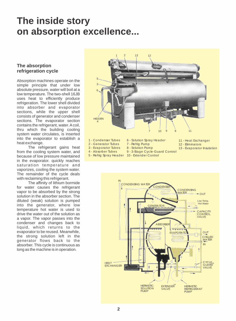
Absorption machines operate on the simple principle that under low absolute pressure, water will boil at a low temperature. The two-shell 16JB uses heat to efficiently produce refrigeration. The lower shell divided into absorber and evaporator sections, while the upper shell consists of generator and condenser sections. The evaporator section contains the refrigerant, water. A coil, thru which the building cooling system water circulates, is inserted into the evaporator to establish a heat exchange.
The refrigerant gains heat from the cooling system water, and because of low pressure maintained in the evaporator. quickly reaches sa tura t ion tempera ture and vaporizes, cooling the system water. The remainder of the cycle deals with reclaiming this refrigerant.
The affinity of lithium bormide for water causes the refrigerant vapor to be absorbed by the strong solution in the absorber section. The diluted (weak) solution is pumped into the generator, where low temperature hot water is used to drive the water out of the solution as a vapor. The vapor passes into the condenser and changes back to l iquid, which returns to the evaporator to be reused. Meanwhile, the strong solution left in the generator flows back to the absorber. This cycle is continuous as long as the machine is in operation.
The inside storyon absorption excellence...
The absorptionrefrigeration cycle
1 - Condenser Tubes2 - Generator Tubes3 - Evaporator Tubes4 - Absorber Tubes5 - Refrig Spray Header
6 - Solution Spray Header7 - Refrig Pump8 - Solution Pump9 - 3-Stage Cycle-Guard Control10 - Extender Control
11 - Heat Exchanger12 - Eliminators13 - Evaporator Insulation
1 2 13 12
5
3
6
7 10 9 8 11
HIDDEN4
2
CONDENSINGWATER OUT
STEAM
CAPACITYCONTROLVALVE
OUT
CHILLEDWATER
IN
IN
CYCLEGUARDVALVE
HERMETICREFRIGERANTPUMP
EXTENDERVALVE
HERMETICSOLUTIONPUMP
HEATEXCHANGER
CONDENSING WATERCONDENSER
GENERATOR
ABSORBER
EVAPORATOR
TM
TM
Low Temp. Hot Water

Low operating costs
The 16JB has the lowest full-load low temperature hot water rate in the industry, ensuring lower operating costs than any other comparable absorption machine!
Part Load energy savings
Energy savings can be significant if the machine is able to operate at l o w e r c o n d e n s e r w a t e r temperatures. In actual operation, design conditions of load and wet-bulb temperature do not frequently occur. Therefore, during much of the operating season, this conservation of energy is possible. 16JB chillers o p e r a t e t r o u b l e f r e e w i t h uncontrolled as low as 45 F. Thus, further savings are realized with 16JB machines thru elimination of a cooling tower bypass system, including an expensive bypass valve, piping, installation and subsequent maintenance.
Enjoy energy savingsat full and part load conditions ...
3 - s t a g e C y c l e - G u a r d a n d ability to use cooler condenser water extender valves: means reduced energy demand and reliable control, even at 45 F there fore grea ter opera t ing entering condenser water! economies.
Extender valve contro l The capacity control valve in the ensures a safe pump suction level by principal means of control of the preventing overdilution. A control 16JB. Additionals control devices device automatically senses the safe maintain safe, stable operation. minimum refrigerant level in the
The revolutionary Cycle- evaporator and adds solution as Guard control prevents over- needed to maintain proper system concentration and crystallization balance. The Extender valve is also problems by automatically adding essential for reliable operation down refrigerant (water) to the absorber if to 45 F entering condenser water, the refrigerant level in the evaporator since it protects the evaporator rises to a pre-set limit. Actually, pump ... the absorber works so Cycle-guard is calibrated in the field effectively that it must be prevented by factory personnel to sense three from absorbing all the refrigerant, different levels of temperature and leaving the evaporator dry. So a concentration. control device senses the safe
This extraordinary control minimum evaporator level and the maintains leaving chilled water Extending balanced operation to the temperature and allows continuos 45 F entering condenser water operation at full load with entering range.condenser water as low as 45 F. The
Continuos and stablePart - load operation
Absorption machines provide continuous and stable part-load operation with lower entering condenser water temperatures, assuring significant operating and energy savings.
- easier servicing,too!
Double sumps cutpump service time
A U-baffle in the lower shell forms two sumps in the shell, allowing storage of refrigerant or solution in one sump while the other side is being serviced. The U-baffles in both the upper and lower shells serve as a natural insulating barrier between sections. Fluids being stored need not be drained or transferred to drums, a factor that greatly reduces services time and expense.
3

Your 16JB has features that substantiallylower maintenance costs
U-bend generator tubes reducecostly tube bundle replacement
Hermetic pump/motor units offer freedom from maintenance, and the ultimate in simplicity and pumping re l i ab i l i t y. Hermet i c des ign eliminates the need for a separate, complicated, and possibly leakproof seal water system and auxiliary city water piping, while providing leak tightness and longer machine life. These pumps have conically shaped
bearings which are lubricated by the fluid being pumped. The solution and refrigerant pumps are hermetically sealed; require no packing glands, machined thrust bearings, magnetic strainers, or monthly servicing. They are fully field serviceable, and
inspection is recommended at six-year intervals.
Another special feature of 16JB absorption liquid chillers is the use of U-bend generator tubes for maintenance-free operation, greatly reducing the likehood of expensive and time-consuming tube bundle replacement.
Each copper-nickel tube is expanded in the tube sheet and tube support sheets to eliminate tube wear. The U-bend configuration allows the entire tube bundle to expand or contract as a unit when subjected to rapid temperature changes. The tube bundle floats and adjust freely as a unit, decreasing tube wear due to thermal stresses and reducing tube bundle failures.
Lithium chromate inhibitor:added corresion protectionyou can check in the field
Lithium chromate inhibitor added to the lithium bromide solution in 16JB absorption chillers provides an extra margin of protection against corrosive damage to internal machine surfaces. It assures easier maintenance at lower costs, and dependable operation.
Lithium chromate is not only an effective corrosion inhibitor, but is also practical to measure and maintain, using the Solution Analysis Test Kit. This portable kit contains the components needed for quick and practical evaluation of inhibitor concen t ra t i on and so lu t i on chemistry - right in the field. The easy-to-use colorimeter shows immediate results ... no more delays or waiting for laboratory analysis ... now solution chemistry can be evaluated at the jobsite, and on-thespot adjustments made, if needed.
Thermal expansion of ordinary tubes resultsin rubbing, wear .
With U-bend tubes, there’s room to expand,no contact or rubbing.
Leakproof hermetic pumpscut maintenance expense
4
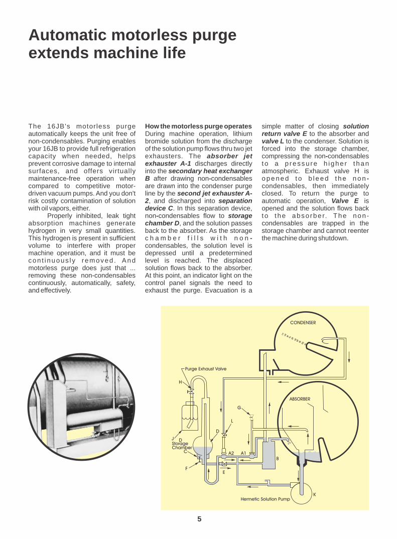
The 16JB's motorless purge How the motorless purge operates simple matter of closing solution automatically keeps the unit free of During machine operation, lithium return valve E to the absorber and non-condensables. Purging enables bromide solution from the discharge valve L to the condenser. Solution is your 16JB to provide full refrigeration of the solution pump flows thru two jet forced into the storage chamber, capacity when needed, helps exhausters. The absorber jet compressing the non-condensables prevent corrosive damage to internal exhauster A-1 discharges directly t o a p ressu re h i ghe r t han surfaces, and offers virtually into the secondary heat exchanger atmospheric. Exhaust valve H is maintenance-free operation when B after drawing non-condensables o p e n e d t o b l e e d t h e n o n -compared to competitive motor- are drawn into the condenser purge condensables, then immediately driven vacuum pumps. And you don't line by the second jet exhauster A- closed. To return the purge to risk costly contamination of solution 2, and discharged into separation automatic operation, Valve E is with oil vapors, either. device C. In this separation device, opened and the solution flows back
Properly inhibited, leak tight non-condensables flow to storage t o t he abso rbe r. The non -absorption machines generate chamber D, and the solution passes condensables are trapped in the hydrogen in very small quantities. back to the absorber. As the storage storage chamber and cannot reenter This hydrogen is present in sufficient c h a m b e r f i l l s w i t h n o n - the machine during shutdown.volume to interfere with proper condensables, the solution level is machine operation, and it must be depressed until a predetermined con t i nuous l y removed . And level is reached. The displaced motorless purge does just that ... solution flows back to the absorber. removing these non-condensables At this point, an indicator light on the continuously, automatically, safety, control panel signals the need to and effectively. exhaust the purge. Evacuation is a
Automatic motorless purgeextends machine life
5
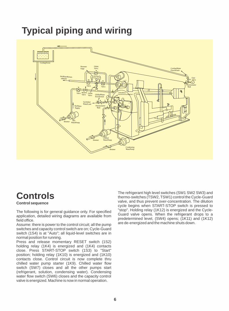
Typical piping and wiring
6
The refrigerant high level switches (SW1 SW2 SW3) and thermo-switches (TSW2, TSW1) control the Cycle-Guard Controlsvalve, and thus prevent over-concentration. The dilution Control sequencecycle begins when START-STOP switch is pressed to "stop". Holding relay (1K12) is energized and the Cycle-The following is for general guidance only. For specified Guard valve opens. When the refrigerant drops to a application, detailed wiring diagrams are available from predetermined level, (SW4) opens; (1K11) and (1K12) field office.are de-energized and the machine shuts down.Assume: there is power to the control circuit; all the pump
switches and capacity control switch are on; Cycle-Guard switch (1S4) is at "Auto"; all liquid-level switches are in normal position for running.Press and release momentary RESET switch (1S2) holding relay (1K4) is energized and (1K4) contacts close. Press START-STOP switch (1S3) to "Start" position; holding relay (1K10) is energized and (1K10) contacts close. Control circuit is now complete thru chilled water pump starter (1K9). Chilled water flow switch (SW7) closes and all the other pumps start (refrigerant, solution, condensing water). Condensing water flow switch (SW6) closes and the capacity control valve is energized. Machine is now in normal operation.

CONTROL WIRING 220V
FUSENSOR
Pt100
TRANSFORMER220V-127 (1T1) TEMPERATURE
CONTROLLER(1ET1)
1K2
1K2
1K5
1K5
1K6
1K6
1K10
1K10
1S2
1K1
1K3
1K4
1K4
1K4
1K4
1K4
1K3
1K5
1K5
1K5
1K6
1K6
1K6
1K7
1K7
1K7
C1
1K8
1K8
1K9
1K9
1K8
C2
R
1K10
1K10
1C1
1KM1
1KM2
1K12
1FO1
1K4
1K9
A
1K11
1F1
1F2
THERMOCONTACTSOLUTION PUMP
THERMOCONTACTREFRIGERANT PUMP
SW8
SW6
SW7
Sw5
OFF
ON 1S3
FU
FU
Sw41
2
3
1S4TSW1
TWS2
SW!
Sw2
Sw3
1F03
LLC
1K11 1KM1
1KM1
1KM2
1KM2
1K12CG
1K1
1K2
CAPACITY CONTROL VALVE
LEGEND ( Continued on next page )
W
M
TRANSFORMER220V-110V (1T1)
ONLY COIL 110 V
1K11
7

Nozzle arrangements
1C1 HOUR COUNTER1F01 MAIN CIRCUIT BREAKER1F03 MAIN CIRCUIT BREAKER1ET-1 TEMPERATURE CONTROLLER1F1 COMPACT STARTER SOL PUMP1F2 COMPACT STARTER REF PUMP1K1,2,4,5,6,7,8,9,10,11,12 CONTACTOR RELAY1K3 TIMING RELAY1KM1 COMPACT STARTER SOL PUMP1KM2 COMPACT STARTER REF PUMP1S2 RESET SWITCH1S3 ROTARY SWITCH ON-OFF1S4 ROTARY SWITCH AUO-HANDC1 CONDENSING WATER PUMP STARTERC2 CHILLED WATER PUMP STARTERCG CYCLE GUARD VALVE
LLC LOW LEVEL CONTROL EXTENDER VALVESW1,2,3 CYCLE GUARD CONTROL SWITCHSW4 LOW LEVEL AND DILUTION SWITCHAW5 PURGE LEVEL SWITCH SW6 COND. WATER PUMP FLOW SWITCHSW7 CHILLED WATER PUMP FLOW SWITCHSW8 LOW TEMPERATURE CUTOUTTSW THERMO SWITCHFU FUSE FACTORY WIRING FIELD WIRING
RUN LIGHT PURGE LIGHT
CYCLE-GUARD LIGHT
A
R
W
LEGEND (Continued)
8
Machine size: 16JB014/028 - 908

9

10
Note: Ratings are based on:44 F Chilled water ?T=10 F85 F Cooling water ?T=15F194 F EnteringHot water ?T=15 F
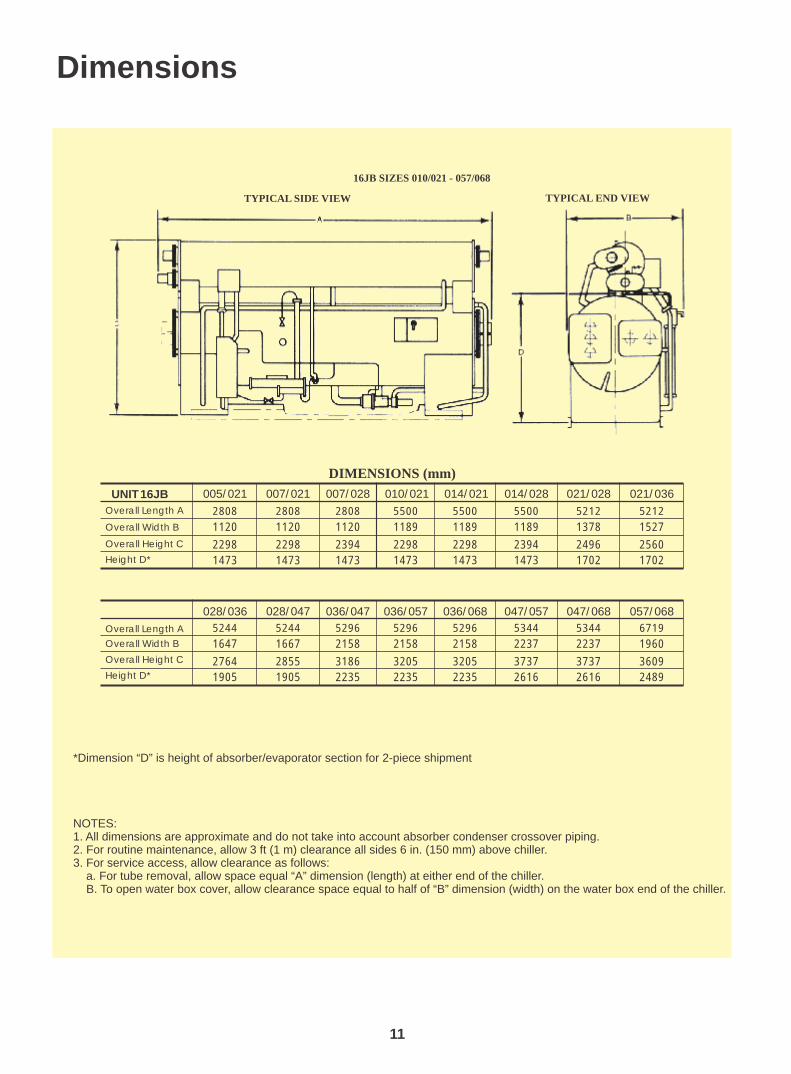
Dimensions
*Dimension “D” is height of absorber/evaporator section for 2-piece shipment
NOTES:1. All dimensions are approximate and do not take into account absorber condenser crossover piping.2. For routine maintenance, allow 3 ft (1 m) clearance all sides 6 in. (150 mm) above chiller.3. For service access, allow clearance as follows: a. For tube removal, allow space equal “A” dimension (length) at either end of the chiller. B. To open water box cover, allow clearance space equal to half of “B” dimension (width) on the water box end of the chiller.
TYPICAL SIDE VIEW
16JB SIZES 010/021 - 057/068
TYPICAL END VIEW
11
UNIT 16JB
DIMENSIONS (mm)
010/021
5500
1189
2298
1473
014/021
5500
1189
2298
1473
014/028
5500
1189
2394
1473
021/028
5212
1378
2496
1702
021/036
5212
1527
2560
1702
Overall Length A
Overall Width B
Overall Height C
Height D*
028/036
5244
1647
2764
1905
028/047
5244
1667
2855
1905
036/047
5296
2158
3186
2235
005/021
2808
1120
2298
1473
007/021
2808
1120
2298
1473
007/028
2808
1120
2394
1473
036/057
5296
2158
3205
2235
036/068
5296
2158
3205
2235
047/057
5344
2237
3737
2616
047/068
5344
2237
3737
2616
057/068
6719
1960
3609
2489
Overall Length A
Overall Width B
Overall Height C
Height D*

Guide SpecificationsHermetic Absorption Liquid Chiller
Size Range: 100 to 522 Tons
Model Number: 16JB
pressure.
3. Final assembly inspection shall consist of ver i fy ing that a l l values, contro ls, instrumentation, pumps, purge components, and all other machine components have been properly installed on the machine.
4. Each unit shall than be checked for overall Part 1 - General appearance and dimensional accuracy.
5. Final inspection shall be performed on each 1.01 SYSTEM DESCRIPTIONunit to check that painting of the unit is as specified, name plate data is correct, and that Electronically controlled, single effect (one-stage) all accessories are furnished as required.absorption liquid chiller utilizing hermetic
refrigerant and solution pumps, lithium bromide 1.03 DELIVERY, STORAGE, AND HANDLINGsolution as the absorbent, and water as the
refrigerant. Low temperature hot water shall be A. Unit shall be stored and handled in accordance supplied to the generator as the heat source.
with the manufacture's recommendations.
1.02 QUALITY ASSURANCE B. Unit shall not be factory-charged with lithium bromide solution to prevent possible internal
A. Chiller performance shall be rated in accordance corrosion damage from occurring should be with ARI Standard 560 (latest edition). inside of the machine be accidentally exposed to
air during shipment and/or installation. Charging B. Chiller shall be manufactured in accordance with of lithium bromide solution shall be performed at
ANSI/ASHRAE 15 (latest edition) Safety Code the job site in accordance with the manufacture's for Mechanical Refrigeration. written instructions.
C. The tube-side of the absorber and evaporator sections (when applicable) and the tube-side of C. One-piece units shall be shipped under vacuum the generator shall be designed, constructed, on the shell-side. Two-piece units shall be and in accordance with ASME Section VIII, shipped with 5 psig (34 kPa) nitrogen pressure.Division 1 requirements.
D. Chiller shall be shipped with nameplates D. Each chiller shall undergo a series of standard indicating name of manufacture, model size,
factory tests to ensure that the unit is leak tight, serial number, and all other pertinent machine that all electrical components operate as data.intended, and that every aspect of unit fabrication meets stringent quality standards in
1.04 WARRANTYaccordance with good practice and the manufacture's quality assurance requirements.
Manufacture shall guarantee the chiller against defects in materials or workmanship for a period of 1. The shell-side of each chiller shall be leak one year from data of initial operation or 18 months tested by pressurizing to 15 psig (103 kPa) from data of shipment, whichever occurs first. with dry air and then checked by spraying a Manufacturer shall provide the labor to repair or soap/water mixture on all welds, tube joints, replace any part found to be defective in material or and/or gasketed joints to identify any major workmanship within the warranty period.leaks. Afterward, a mass spectrometer test
shall be performed by evacuating the unit to Part 2 - Products0.10 mm Hg absolute, covering the machine
with a vinyl tent and introducing helium gas 2.01 EQUIPMENTunder the tent. Any remaining leaks will allow
the helium to be drawn into the shell-side of A. General:the machine. The acceptable total leak rate as
measured by the mass spectrometer test shall Absorption liquid chiller shall include evaporator, not exceed 0.0002 cc/sec standard air.absorber, condenser, generator, solution heat exchanger, refrigerant/solution pumps, purge 2. The tube-side of the evaporator, absorber and system, piping, wiring, controls, and auxiliaries. condenser shall be hydrostatically tested at Shipment of the machine shall be in 1 or 2 1.5 times rated design pressure and held for 1 piece(s), depending on model size. Initial charge hour. A pneumatic test shall be performed on of lithium bromide shall be included with the the generator at 1.25 times rated design chiller for charging at the job site. Generator shall
12

be designed for operation on low temperature requirements on the tube-side.hot water as specified on the equipment schedule. A U-baffle shall be provided in both the 4. A solution heat exchanger shall be an integral upper and lower shell to serve as a natural part of the machine to increase efficiency by insulating barrier between sections. The double pre-heating weak solution on the tube-side sump formed by the U-baffle in the bottom of the with strong solution on the shell-side. Tube absorber-evaporator section shall allow material for this heat exchanger shall be temporary storage of refrigerant or solution, carbon steel.thereby reducing service time and expense by alleviating the need to remove the fluids from the 5. Spray heads for the evaporator and absorber machine during service and/or maintenance shall be fabricated of a corrosion-proff operations. material to ensure continuous, high efficiency
operation.B. Operating Characteristics:
6. Heat exchanger tube material and minimum 1. Chiller operation shall be characteristic of a wall thickness shall be contingent on the type
single effect absorption cycle. The weak of corrosion inhibitor used in the machine. solution pumped from the absorber to the The following tube specifications shall apply generator shall initially pass through a solution to ensure long machine life and continuous heat exchanger to improve operating operation:efficiency by preheating the weak solution on Evaporatorthe tube side with the strong solution returning Absorberfrom the generator on the shell-side. Condenser
Generator2. Unit shall be capable of continuous operation
from 100% to 10% capacity, with entering D. Pump/Motors:condenser water temperatures as low as 55 F
O Refrigerant and solution pump/motors shall be (13 C) without the need for a cooling tower self-contained, leakproof, hermetic type, without bypass valve. Thermostat on/off control of the pump seals, isolation valves, or external seal cooling tower fan is recommended when water system to minimize air leakage into the cooling water temperature falls below 55 F
O machine. Each pump casing shall be welded into (13 C).suction and discharge lines and factory installed a n d s h a l l i n c l u d e s p r i n g - l o a d e d , C. Heat Exchanger:wearcompensating, tapered carbon bearings. Lubrication and cooling shall be accomplished 1. All heat exchanger shall be off shell and tube by the fluid being pumped; auxiliary water piping construction with shells, tube-sheets, tube for cooling and lubrication shall not be support sheets, and water-boxes fabricated acceptable. Pump/motor assemblies shall be of carbon steel. All heat exchanger shall designed for 50,000 - 60,000 hours of normal incorporate straight tubes, except for the operation between inspections. If pump/motor generator which shall use U-tubes. All tubes assemblies are furnished with less than a design shall be rolled into grooved tube-sheets and of 50,000 - 60,000 hours of normal operation expanded into tube support sheets. All tubes between inspections, they must be provided with shall be individually replaceable.isolation valves and a bearing monitoring system to aid in diagnosing and performing on-going 2. The evaporator, absorber, and condenser maintenance.water-boxes shall be designed for 150 psig
(1034 kPa) working pressure and shall be E. Purge Systemsupplied with nozzle-in-head (NIH), type C
water-boxes. Removable water-box covers An automatic motorless purge system shall be shall permit access to all tubes from either furnished to provide a continuous purging action end. All water-boxes shall be provided with whenever the chiller is in operation to assure vent and drain connections. Nozzle long machine life and efficient performance. connections shall be of the flanged-end type Non-condensables shall be removed from the unless otherwise noted.absorber by a liquid educator, which shall use flow from the solution pump to create a suction. 3. The generator tube bundle shall consist of U-Non-condensables shall be stored external to bend tubes secured to the tube sheet on one the unit and shall be prevented from diffusing end only to allow for thermal expansion and back into the machine when the unit is not contraction. The tube-side of the generator operating. Evacuation of the external storage shall be designed for 250 psig (1752 kPa) chamber shall be accomplished by manually working pressure. All generators shall be positions valves to pressurize the chamber with designed, constructed, and in accordance lithium bromide solution and exhausting it to with ASME Section VIII, Division 1
copper, externally finnedcooper, prime surfacecopper, prime surface
90/10 CuNi, prime surface
13

atmosphere. If the purge system design is such d. High motor winding temperature - that it requires a vacuum pump, then it shall be refrigerant/solution pumpunit mounted and wired to the control center by e. High motor amperage - refrigerant/solution the chiller manufacture. pump
f. Low chilled water flowF. Controls: g. Low cooling water flow
1. Each chiller shall include a factory mounted 2. Chiller shall include a rupture disk to protect and wired control center with lock-able door. against accidental over-pressure.Machine operation shall be continuously controlled and monitored with the chiller H. Electrical Requirements:operational status displayed on the front of the panel. Panel components shall include an 1. Power supply to the unit shall be 3-ph, 50Hz electronic capacity control module, fused with voltages of (380 v) specified on the disconnect switch, pump constactors, equipment schedule.ambient-compensated 3-phase pump over loads, mul t i - tap contro l power 2. Contractor shall supply and install the transformer, elapsed time indicator, terminal electronical power line and all auxiliary blocks, relays, auto/manual capacity control electrical protection devices per local code switch, refrigerant and solution pump requirements and as indicated necessary by operational switch, exhaust purge light, and the chiller manufacturer.all other necessary safeties and control for proper machine operation. 3. Contractor shall supply and install electrical
wiring and devices required to interface the 2. Capacity control shall be electronic as chiller controls with the building control
specified on the equipment schedule by system, if applicable.regulating the flow of low temperature hot water to the generator in response to the I. Piping Requirements:leaving chilled water temperature. The output from the capacity or closing of the capacity 1. Piping and instrumentation for the chilled water, control valve. cooling water steam and condensate piping (or
hot water supply and return piping) shall be 3. Provisions for interlocking control of the chilled supplied and installed by the contractor/owner.
water pump, condenser water pump, and cooling tower fans shall be included in the 2. Absorber-condenser crosser piping shall be panel as standard. furnished by the contractor/owner or the chiller
manufacturer as specified on the equipment 4. Unit shall include and automatic concentration schedule.
control system to prevent over-concentration and over-dilution of the lithium bromide 3. Chilled water and condenser water flow switch solution at all operating conditions. Operation shall be field installed and supplied by either the shall be based on monitoring concentration chiller manufacturer or the contractor/owner.(Via refrigerant level in the evaporator) and temperature of the solution, and transforming 4. Piping from the rupture disk shall be provided water from the evaporator to the absorber to and installed by the contractor/owner and piped limit concentration when conditions warrant. in accordance with the chiller manufacturer's Over-dilution shall also be controlled via a low written instructions and any local jurisdictional level switch in the evaporator. requirements.
5. Automatic dilution cycle shall lower the J. Thermal insulationconcentration of the lithium bromide solution to prevent possible crystallization in the heat Evaporator surfaces shall be factory insulated exchanger. Control shall be turned off when insulation of refrigerant pump, sump, piping and refrigerant level falls to a preset level in the chilled water headers, in addition to any hot evaporator. Control shall be activated by surfaces shall be field supplied and installed on chiller shutdown. the machine. Chiller manufacturer shall
recommend material and specify the area to be G. Machine Safety Devices: insulated.
1. Machine safety and limit devices shall be K. Sound Levelincluded as follows:a. high refrigerant level - evaporator (limit) The overall sound pressure level of the chiller b. Low refrigerant level - evaporator (limit) shall not exceed 80 dbA measured per ARI c. Low refrigerant temperature Standard 575 (latest edition).
14

L. Start-up:
1. Unit manufacturer shall provide a factory-trained service representative, employed by the chiller manufacturer, to perform and/or supervise chiller pressure test (when required), charge chiller with refrigerant (water) and lithium bromide solution, place unit into operation and calibrate all controls in accordance with the manufacturer's written startup, operating, and maintenance instructions.
2. After unit start-up has been performed, the same factory representative shall be available for a period of instruction not to exceed 4 hours to instruct the owner's personnel in the proper start-up, operating, and maintenance procedures.
3. Manufacturer shall provide the following literature:a. installation Instructionsb. Start-up, operating and Maintenance instructionsc. Field Wiring Diagrams.
M. Options and Accessories:
1. High-Pressure Water-boxes:Water-boxes rated for 250 psig (1725 Kpa) working pressure shall be furnished when specified on the equipment schedule.
2. Generator:A generator designed, built, and in accordance with ASME Sections VIII, Division 1 requirements with a design working pressure of 250 psig (1725 Kpa) shall be furnished for low temperature hot water applications when specified on the equipment schedule.
3. Absorber-Condenser Crossover Piping:Crossover piping connecting the absorber to the condenser shall be furnished when specified on the equipment schedule.
4. Shipping Configuration:ANSI 150 psig (1034 KPa) RF (raised face) flanges shall be furnished on all water-box nozzle connections when specified on the equipment schedule.
6. Chilled and condenser Water Flow Switches:Chilled water and condenser water flow switches, rated for 250 psig (1724 KPa), shall be factory supplied for field installation when specified on the equipment schedule.
15

