low pressure dc-plasma system for the modification of ... chalad yuenyao.pdf · low pressure...
TRANSCRIPT

Sains Malaysiana 46(5)(2017): 783–793 http://dx.doi.org/10.17576/jsm-2017-4605-13
Low Pressure DC-Plasma System for the Modification of Polymeric Membrane Surfaces
(Sistem DC-Plasma Tekanan Rendah untuk Pengubahsuaian Permukaan Membran Polimer)
CHALAD YUENYAO*, THAWAT CHITTRAKARN, YUTTHANA TIRAWANICHAKUL & HIDEKI NAKAJIMA
ABSTRACT
The main objectives of this work were to develop a lab-scale direct current (DC) glow discharges plasma system for modification of organic and inorganic membranes. Characteristics of plasma system were presented under the discharge of five gases (Ar, N2, air, O2, and CO2). A Langmuir double probe was used for the evaluation of the electron temperature (Te) and electron density (ne) of plasmas. The current and voltage (I-V) characteristic curves were analyzed. Relationships between breakdown voltage (VB) of gases and products of gas pressure and inter-electrode gap (pd) were studied in form of Paschen curves. The results showed that Te of plasma in various gases was in the range of 4-13 eV, while the ne varied between 108 and 109 cm-3. The plasma generated at different gas pressure and applied voltage is in the normal and abnormal modes. Finally, the constructed DC-plasma system was utilized for modification of polymeric membrane surfaces. Treatment time, discharge power and type of gas were varied. The tailoring of membrane surfaces was analyzed through the water contact angle and percent-weight loss (PWL) measurements, DMTA, AFM, XPS and FTIR spectrum. It could be shown that DC-plasma from this system can be used to modify the surface of polymeric membranes.
Keywords: Breakdown voltage; characterization; DC discharge plasma; Langmuir double probe; polymeric membrane
ABSTRAK
Objektif utama kajian ini adalah untuk membangunkan satu skala makmal arus terus (DC) cahaya buangan sistem plasma untuk pengubahsuaian membran organik dan bukan organik. Pencirian sistem plasma telah ditunjukkan dengan penyingkiran lima gas (Ar, N2, udara, O2 dan CO2). Prob berganda Langmuir digunakan untuk menilai suhu elektron (Te) dan ketumpatan elektron (ne) plasma. Pencirian arus dan voltan (I-V) lengkung dianalisis. Hubungan antara gas pembelah voltan (VB) dan produk tekanan gas serta jurang antara elektrod (pd) telah dikaji dalam bentuk lengkung Paschen. Keputusan menunjukkan bahawa Te plasma dalam pelbagai gas adalah dalam lingkungan 4-13 eV, manakala ne berjulat antara 108 dan 109 cm-3. Plasma yang dihasilkan pada tekanan gas yang berbeza dan voltan gunaan adalah dalam mod normal dan tidak normal. Kesimpulannya, sistem DC-plasma yang dibina digunakan untuk pengubahsuaian permukaan membran polimer. Masa rawatan, kuasa pelepasan dan jenis gas telah berubah. Pengukuran permukaan membran dianalisis melalui sudut sentuh air dan pengukuran kehilangan peratus berat (PWL), spektrum DMTA, AFM, XPS dan FTIR. Ia dapat ditunjukkan bahawa DC-plasma daripada sistem ini boleh digunakan untuk mengubah suai permukaan membran polimer.
Kata kunci: Membran polimer; pecahan voltan; pencirian; penyingkiran DC plasma; prob berganda Langmuir
INTRODUCTION
Several types of power sources can be used to generate plasma, such as radiofrequency (RF), microwave (MW), photons and DC high voltage. Although the density of plasma generated by using MW and RF as power sources is higher than those of DC plasma sources, the DC plasma is technically relatively easy, no matching unit is required and it is of low cost compared to the other electromagnetic sources. Also, the DC plasma systems are simple operation and low maintenance cost. Typically, plasmas generated from DC power sources are divided into several regions, like the Townsend or dark discharges and glow discharges and arc plasma depending on their operating voltage and current (Bogaerts 1996; Roth 2000). Discharge parameters can be determined by various types of Langmuir probes (Lieberman & Lichtenberg 2005; Naz et al. 2011), while
current and voltage characteristics of different plasma gases can also be measured by current and high voltage probes. Therefore, the development of a Langmuir probe and a current probe are necessary steps for each plasma system (Nisha et al. 2006; Singh et al. 2009). In the surface processing technology of materials, DC plasma systems are usually operated at low gas pressures as electrons can attain to high energies (Pandiyaraj et al. 2009; Sanaee et al. 2011). On the contrary, gas particles can remain at low energies and temperatures (D’Agostino 1990). Also, to avoid any damage to the surface of polymeric membranes, most of the plasmas were generated at lower power and pressure levels (Pandiyaraj et al. 2009). Glow discharge plasmas have been used over two decades to improve final properties of polymeric membrane surfaces (D’Agostino 1990). In 2012, Modarresi et al.

784
treated polysulfone (PSF) membranes with low-frequency O2-plasma. They found that the permeation of CO2 and CH4 through the plasma treated membranes has increased due to surface ablation and surface polarization and also found that the hydrophilic property of PSF membranes significantly enhanced with increasing treatment time and discharge power. Surface properties of polypropylene (PP) films were improved by DC-plasma using air as processing gas. It was found that surface free energy (SFE) of PP films increased depending on treatment time. In addition, the oxygen-containing polar group was introduced on the PP film top surface (Pandiyaraj et al. 2009). Polar functional groups were introduced to the PSF ultrafiltration membrane surfaces after treated by CO2 plasma using RF as power source (Wavhal & Fisher 2005). It was clear that the hydrophilic properties and performance of PSF membranes have been improved by N2 plasma treatment. Besides, the etching effects can occur just after two minutes of plasma treatment. The average pore size of PSF membranes increased and the pore size distribution was wider (Gancarz et al. 2000). For Ar-plasma, it was utilized to modify the polyethylene (PE) surface. The results showed that the contact angle in sessile drop mode decreases significantly in dependence of the discharge power and treatment time (Svorcik et al. 2006). For the surface treatment of polymeric membranes by plasma generation from non-polymerizing gases such as Ar, N2, air, O2, and CO2, it was clear that the etching process and the formation of cracks can occur depending on plasma conditions. These effects will appear faster and larger if higher discharge powers were used. However, when discharge power reaches a certain value, the deposition process is switched on (Volkov et al. 2016). Normally, etching of membranes increases with longer treatment time and can be observed by PWL measurements (Matsuyama et al. 1995; Pandiyaraj et al. 2008; Wavhal & Fisher 2005). Permeation of N2 gas through plasma treated PSF ultrafiltration membranes dispersed for a prolonged treatment time. This dispersion shows the competition between etching or degradation and deposition processes. These variations of permeation values are related to the contact angle of membrane surfaces (Vidaurre et al. 2001). In the present work, a lab-scale DC-plasma system for modification of polymeric membrane surfaces was developed. The operational testing and characterization of this system was conducted through the discharge of various gases. Paschen curves of each discharges were evaluated and I-V characteristics curves were discussed in details. Furthermore, a Langmuir double probe (LDP) was constructed and used to evaluate the plasma parameters, such as Te and ne. In order to ensure that the system can be practical used to alter polymeric materials, samples of polymeric membranes were treated. The working gas (Ar and O2), treatment time and discharge power were varied. Modifications of membrane surfaces were evaluated by contact angle measurement in sessile drop mode using a video based optical contact angle measuring
instruments (Model OCA 15EC, Data Physics Instruments GmbH, Germany). The etching process was monitored through the PWL of membrane samples at different plasma conditions. Mechanical properties and functional group creations on membrane surfaces were studied by dynamic mechanical thermal analysis (DMTA) and attenuate total reflectance Fourier transform infrared spectroscopy (ATR-FTIR), respectively. Atomic force microscope (AFM) and X-ray photoelectron spectroscopy (XPS) were employed to analyze the surface roughness and chemical change on the surface of membrane samples.
MATERIALS AND METHODS
EXPERIMENTAL SETUP
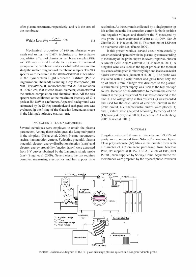
A schematic diagram of the constructed DC plasma system is shown in Figure 1. The main components of this system are a high vacuum system, discharge chamber, rotary and diffusion pump, Pirani and penning gauges, controlling valves and water chiller. Additionally, two parallel electrodes with the dimension of 200 mm in diameter and 7 mm in thickness were incorporated in the system. The outer side of the electrodes is coated with an epoxy of about 2-3 mm in thickness and also coated with Teflon to control the ejected electrons. The inter-electrode gap can be adjusted from 0 to 60 mm. The chamber is made of stainless steel (SS304) tube with the dimension of 255 mm in diameter and 381 mm in length. It has ten ports for connection with various components as mentioned above. The DC power supply of 1,200 Vmax and 3 A is used to generate plasma. In order to control the electrical current flowing in system and draining of electrical current from the capacitor’s tank, two resistors of 100 W, 500 W and 15 kW, 225 W were connected in series and parallel with the circuit, respectively. Plasma patterns generated in the chamber were observed through an acrylic transparent window with a diameter of 97 mm. The discharge power was calculated through the voltage dropped (Vd) on the 100 W resistor connected in series to the anode electrode. The low pressure inside the plasma chamber was reached using a rotary (Edwards EDM12A, 14 CMH) and diffusion (Leybold, 300 L/M) pumps. In order to acquire data for plotting Paschen curves, the inter-electrode gap was adjusted from 1.0 to 4.0 cm while the pressure was controlled between 0.05 to 2.0 mbar. On the other hand, the inter-electrode gap was fixed at about 2.0 cm as the pressure was adjusted between 0.05
and 2.0 mbar. In order to confirm the practical use of the system, the samples of polymeric membrane were treated. The alteration of membrane surfaces was examined through the contact angle measurement. The weight of membrane samples was measured to evaluate the etching effects. PWL were calculated by using (1) (Vijayalakshmi et al. 2012; Wavhal & Fisher 2005; Yang et al. 2009), where W0 and Wt are the weight of the membrane before and
785
after plasma treatment, respectively; and A is the area of the membrane.
Weight Loss (%) = . (1)
Mechanical properties of PSF membranes were analyzed using the DMTA technique to investigate degradation effects of plasma on membrane samples. FTIR and XPS was utilized to study the creation of functional groups on the membrane surfaces while AFM was used to study the surface roughness of membrane samples. The XPS spectra were measured at the SUT-NANOTEC-SLRI beamline in the Synchrotron Light Research Institute (Public Organization, Thailand). Scanning X-ray Microprobe (PHI 5000 VersaProbe II, monochromatized Al Kα radiation at 1486.6 eV, 100 micron beam diameter) characterized the surface composition and chemical state. All the XPS spectra were calibrated at the maximum intensity of C1s peak at 284.8 eV as a reference. A spectral background was subtracted by the Shirley’s method, and each peak area was evaluated in the fitting of the Gaussian-Lorentzian shape in the Multipak software (ULVAC-PHI).
EVALUATION OF PLASMA PARAMETERS
Several techniques were employed to obtain the plasma parameters. Among these techniques, the Langmuir probe is the simplest (Nisha et al. 2006). Plasma parameters, such as ion saturation current, Te, floating potential, plasma potential, electron energy distribution function (EEDF) and electron energy probability function (EEPF) were extracted from I-V curves obtained by the Langmuir single probe (LSP) (Singh et al. 2009). Nevertheless, the LSP requires complex measuring electronics and has a poor time
resolution. As the current is collected by a single probe tip it is unlimited to the ion saturation current for both positive and negative voltages and therefore the Te measured by this probe is over estimated (Castro et al.1999; Naz & Ghaffar 2011; Naz et al. 2011). This problem of LSP can be overcome with LDP (Franz 2009). In this present work, a LDP and circuit were carefully constructed and operated with the plasma system according to the theory of the probe shown in several reports (Johnson & Malter 1950; Naz & Ghaffar 2011; Naz et al. 2011). A tungsten wire was used as the tip of probe as the thermal resistance of tungsten is relatively high and it also can resist harder environments (Bennett et al. 2010). The probe was insulated with a plastic rubber and glass tube; only the tip of about 3 mm in length was disclosed to the plasma. A variable DC power supply was used as the bias voltage source. Because of the difficulties to measure the electric current directly, a resistor of 50 kW was connected to the circuit. The voltage drop in this resistor (Vr) was recorded and used for the calculation of electrical current in the probe circuit. I-V characteristic curves were plotted. Te and ne values were analyzed according to theory of LDP (Elghazaly & Solyman 2007; Lieberman & Lichtenberg 2005; Naz et al. 2011).
MATERIALS
Tungsten wires of 1.0 mm in diameter and 99.95% of purity were purchased from Nilaco Corporation, Japan. Clear polycarbonate (PC) films in the circular form with a diameter of 4.7 cm were purchased from Nuclear Pore, SPI supplies #E00157, U.S.A. Pellets of PSF (Udel P-3500) were supplied by Solvay, China. Asymmetric PSF membranes were prepared by the dry/wet phase inversion
FIGURE 1. Schematic diagram of the DC glow discharge plasma system and Langmuir double probe
786
technique following several reports (Chen et al. 20093; Lee et al. 2000; Pesek & Koros 199). The wet thickness of PSF film was controlled at about 150 mm. Three layers of clear plastic tape were used to control the wet thickness of the nascent PSF membranes. Thickness of plastic tape was measured by a digital micrometer (Mituyoto, 0.001 mm, IP65 Coolant proof standard type, Series 293).
CONSTRUCTED DC-PLASMA SYSTEM
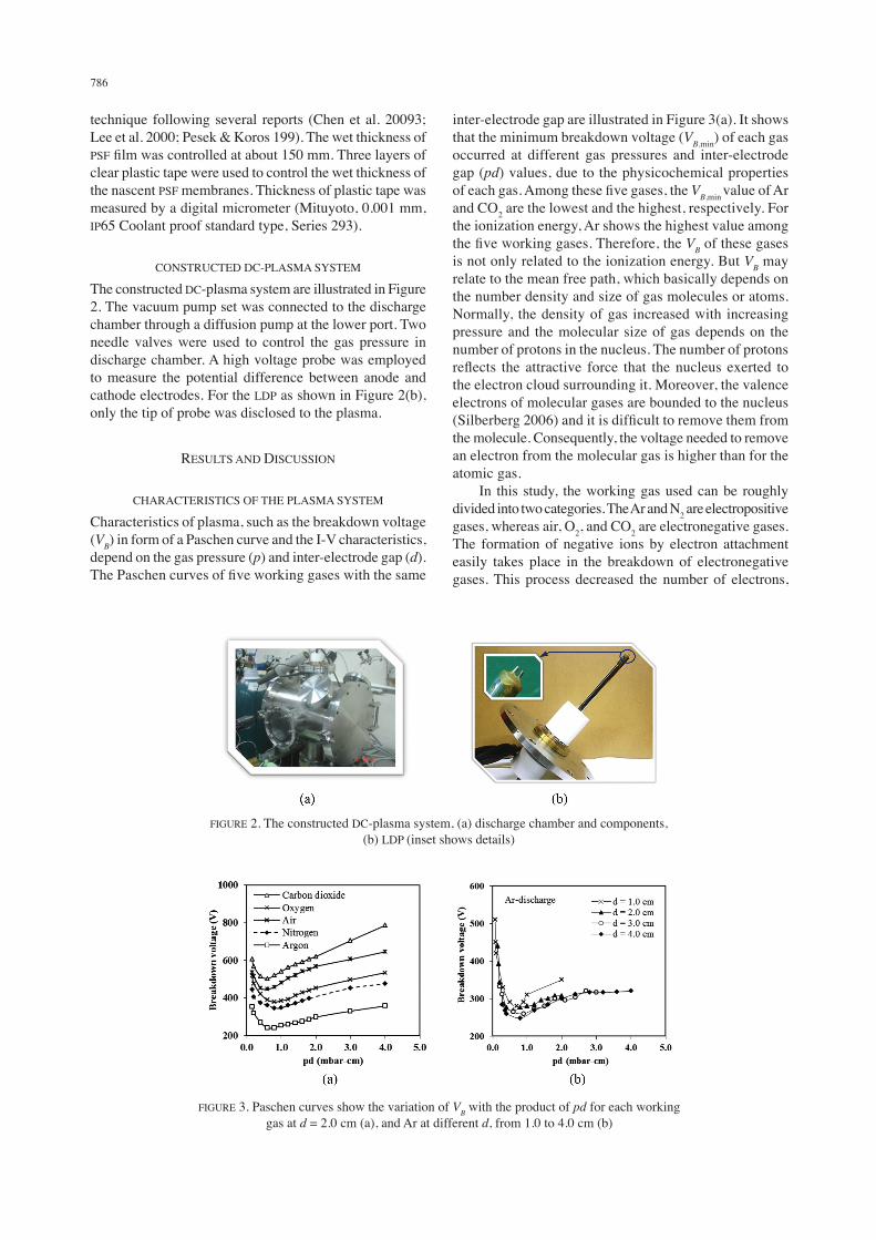
The constructed DC-plasma system are illustrated in Figure 2. The vacuum pump set was connected to the discharge chamber through a diffusion pump at the lower port. Two needle valves were used to control the gas pressure in discharge chamber. A high voltage probe was employed to measure the potential difference between anode and cathode electrodes. For the LDP as shown in Figure 2(b), only the tip of probe was disclosed to the plasma.
RESULTS AND DISCUSSION
CHARACTERISTICS OF THE PLASMA SYSTEM
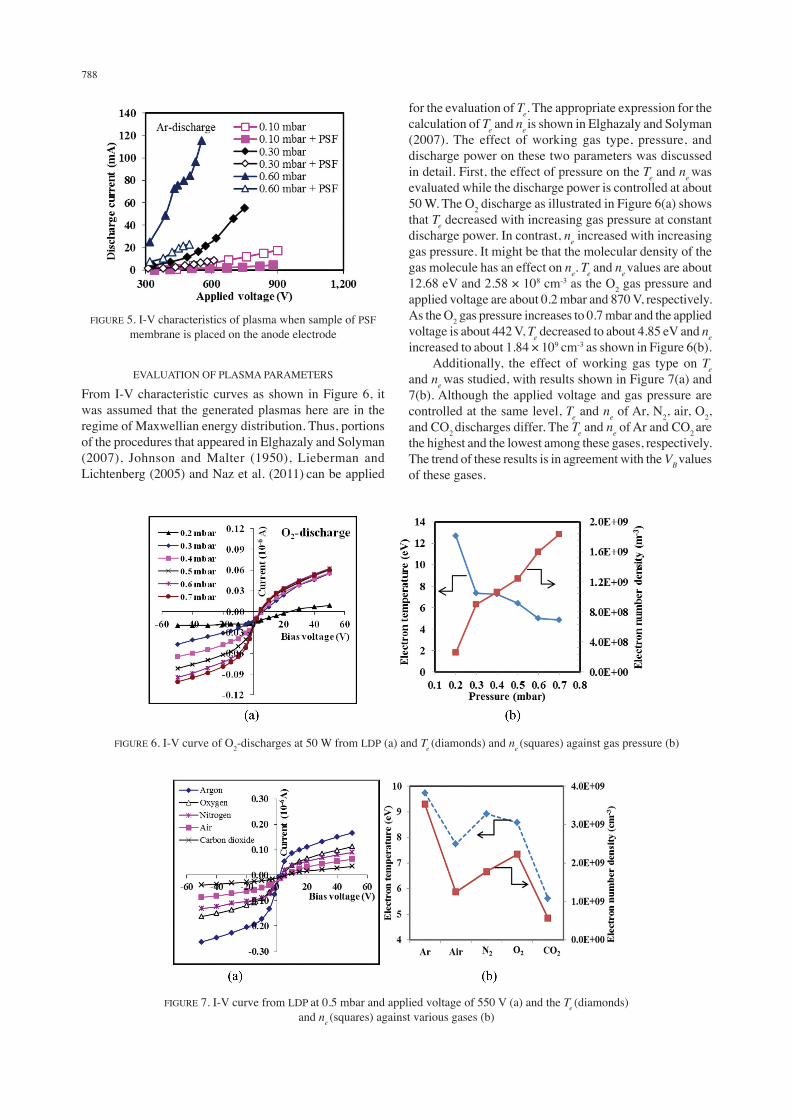
Characteristics of plasma, such as the breakdown voltage (VB) in form of a Paschen curve and the I-V characteristics, depend on the gas pressure (p) and inter-electrode gap (d). The Paschen curves of five working gases with the same
inter-electrode gap are illustrated in Figure 3(a). It shows that the minimum breakdown voltage (VB,min) of each gas occurred at different gas pressures and inter-electrode gap (pd) values, due to the physicochemical properties of each gas. Among these five gases, the VB,min value of Ar and CO2 are the lowest and the highest, respectively. For the ionization energy, Ar shows the highest value among the five working gases. Therefore, the VB of these gases is not only related to the ionization energy. But VB may relate to the mean free path, which basically depends on the number density and size of gas molecules or atoms. Normally, the density of gas increased with increasing pressure and the molecular size of gas depends on the number of protons in the nucleus. The number of protons reflects the attractive force that the nucleus exerted to the electron cloud surrounding it. Moreover, the valence electrons of molecular gases are bounded to the nucleus (Silberberg 2006) and it is difficult to remove them from the molecule. Consequently, the voltage needed to remove an electron from the molecular gas is higher than for the atomic gas. In this study, the working gas used can be roughly divided into two categories. The Ar and N2 are electropositive gases, whereas air, O2, and CO2 are electronegative gases. The formation of negative ions by electron attachment easily takes place in the breakdown of electronegative gases. This process decreased the number of electrons,
FIGURE 2. The constructed DC-plasma system, (a) discharge chamber and components, (b) LDP (inset shows details)
FIGURE 3. Paschen curves show the variation of VB with the product of pd for each working gas at d = 2.0 cm (a), and Ar at different d, from 1.0 to 4.0 cm (b)

787
which is quite important for the breakdown of a gas. In consequence, the breakdown in air, O2 and CO2 is higher than in Ar and N2 gases. In this current work, the VB,min of Ar gas as shown in Figure 3(b) decreased with increasing inter-electrode gap from 1.0 to 4.0 cm. This is similar to the breakdown of the other four gases. In brief, the experimental results showed that the VB of gases complies with the Paschen’s law, where the gas pressure varies while the inter-electrode gap is constant (Chiad et al. 2009; Lisovskiy et al. 2000). VB,min values occurred at higher supply voltages and shifted to a higher pd-parameter, while the inter-electrode gap decreased from 4.0 to 1.0 cm as illustrated in Figure 3(b). Furthermore, a comparison of VB for Ar, N2, O2 and CO2 at the same pd as shown in Figure 3(a) showed that VB for Ar is the lowest though the ionization energy of Ar is the highest among the gases used. Figure 4(a) to 4(d) shows the I-V characteristics of the gas discharge plasma at different pressures of CO2, N2, Ar, and O2, respectively. From these figures, the discharge current increased gradually if the discharge was generated at lower gas pressures of 0.09 and 0.1 mbar. Nevertheless, the current increases faster when the gas discharges were created at higher pressures of 0.5, 0.6 and 0.7 mbar. Typically, the electrical discharges in gases are subdivided into several modes according to their I-V characteristics (Bogaerts 1996; Lieberman & Lichtenberg 2005; Raizer
1991; Roth 2000). The gas discharge is called ‘Towsend’ or ‘dark self-sustained’ and ‘corona’ and ‘sub-normal glow’ for discharge where the discharge current is in the range of about 10-12-10-5A and 10-5-10-4 A, respectively. In this study, discharges of these gases at pressures of about 0.07-0.10 mbar are in the normal and abnormal glow regions, while discharges at pressure levels higher than 0.10 mbar are only in the abnormal glow region. In this case it is required to generate a stable or cold plasma at higher voltage (>850 V) with this DC-plasma system and then the pressure has to be initiated at 0.10 mbar or lower. Temperature in the reactor, especially at the cathode and anode electrodes, increased relatively fast if the plasma was generated at high gas pressures with higher voltage. Generally, the polymeric membrane materials are sensitive to elevated temperatures. In order to make use of the DC glow discharge from this plasma system for the treatment of polymeric membrane surfaces, the operator has to realize these boundary conditions. The experimental results indicated that the required applied voltage to generate the same discharge current increased when a sample of PSF membrane of 7´14 cm in size and about 100 mm in thickness is placed on the anode electrode as illustrated in Figure 5. Consequently, the calibration of the discharge power with a sample of membrane is required before using this plasma system to modify polymeric membrane surfaces.
FIGURE 4. I-V characteristics of DC plasma using CO2 (a), N2 (b), Ar (c), and O2 (d) as working gas
788
EVALUATION OF PLASMA PARAMETERS
From I-V characteristic curves as shown in Figure 6, it was assumed that the generated plasmas here are in the regime of Maxwellian energy distribution. Thus, portions of the procedures that appeared in Elghazaly and Solyman (2007), Johnson and Malter (1950), Lieberman and Lichtenberg (2005) and Naz et al. (2011) can be applied
for the evaluation of Te. The appropriate expression for the calculation of Te and ne is shown in Elghazaly and Solyman (2007). The effect of working gas type, pressure, and discharge power on these two parameters was discussed in detail. First, the effect of pressure on the Te and ne was evaluated while the discharge power is controlled at about 50 W. The O2 discharge as illustrated in Figure 6(a) shows that Te decreased with increasing gas pressure at constant discharge power. In contrast, ne increased with increasing gas pressure. It might be that the molecular density of the gas molecule has an effect on ne. Te and ne values are about 12.68 eV and 2.58 × 108 cm-3 as the O2 gas pressure and applied voltage are about 0.2 mbar and 870 V, respectively. As the O2 gas pressure increases to 0.7 mbar and the applied voltage is about 442 V, Te decreased to about 4.85 eV and ne increased to about 1.84 × 109 cm-3 as shown in Figure 6(b). Additionally, the effect of working gas type on Te and ne was studied, with results shown in Figure 7(a) and 7(b). Although the applied voltage and gas pressure are controlled at the same level, Te and ne of Ar, N2, air, O2, and CO2 discharges differ. The Te and ne of Ar and CO2 are the highest and the lowest among these gases, respectively. The trend of these results is in agreement with the VB values of these gases.
FIGURE 5. I-V characteristics of plasma when sample of PSF membrane is placed on the anode electrode
FIGURE 6. I-V curve of O2-discharges at 50 W from LDP (a) and Te (diamonds) and ne (squares) against gas pressure (b)
FIGURE 7. I-V curve from LDP at 0.5 mbar and applied voltage of 550 V (a) and the Te (diamonds) and ne (squares) against various gases (b)

789
TREATMENT OF POLYMERIC MEMBRANE BY DC-PLASMA
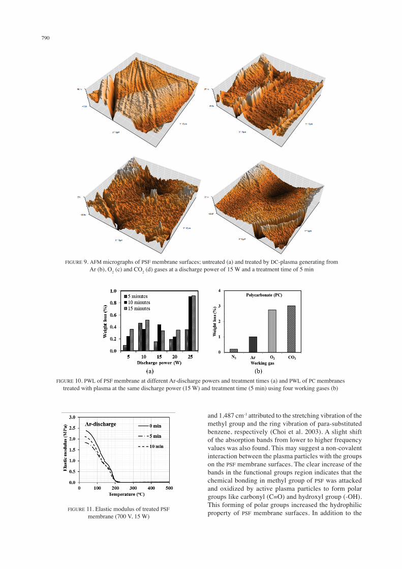
Typically, the effect of plasma on polymeric membrane surfaces can be divided into two main processes depending on whether a working gas or monomer is used. The etching or degradation and deposition processes will take place if the used gas is a non-polymerizing gas (Bryjak et al. 2000; D’Agostino 1990; Khulbe et al. 2010; Lieberman & Lichtenberg 2005; Vidaurre et al. 2001). On the other hand, the polymerization process will take place when a polymerizing gas or monomer is utilized (Agostino 1990; Chu et al. 2002). In this present work, only non-polymerizing gases were used. Etching processes and functional group creations, therefore, are investigated in detail. Figure 8(a) shows the variation of water contact angle of PSF membranes at different plasma treatment times. It was shown that water contact angle decreased sharply during the first short treatment time and then dispersed during a prolonged treatment (Yuenyao et al. 2012). This may due to the competition between the etching effect and the deposition process (Vidaurre et al. 2001). The results also showed that water contact angle of PSF membranes after prolonged treatment by Ar and N2 plasmas are quite smaller dispersed than for O2 and CO2 plasmas, because the plasma etching processes from inert gases (Ar and N2) might be lower than from reactive gases. The water contact angle of PC membranes after treated by plasmas generating from different working gases drastically decreased when they are treated at low power. However, it is quite dispersed after treated by the same plasma at higher power as illustrated in Figure 8(b). This is due to the creation of etching effects that took place more often at higher discharge powers (D’Agostino 1990). AFM micrographs as shown in Figure 9 show the morphological structure of PSF membranes both before and after plasma treatment. It was found that average surface roughness (Sa) was about 26.24, 8.70, 10.37 and 12.19 for untreated, Ar, O2 and CO2 plasmas treated membranes, respectively. Sa of PSF membranes treated by plasmas from reactive gases (O2 and CO2) are higher than by plasma from inert gas (Ar). This result confirmed that etching process from plasma generating from reactive (or electronegative) gases is higher took place than from inert gas. Furthermore, PWL increased with increasing plasma treatment time and
discharge power as shown in Figure 10(a). Thus the PWL of PC membranes depends on the type of working gas, as well. As illustrated in Figure 10(b), PWL is higher when the membrane was treated with plasmas from electronegative gases, namely O2 and CO2. It was known that the plasma etching process is related to the density and energy of electrons and ions. Between electrons and negative ions, the ions play a more important role in the etching process than electrons (Agostino 1990). For the discharge of electronegative gases, the formation of negative ions by the electron attachment takes place easily. In this study, the PWL is not as high as expected because of the competing etching and deposition processes (Vidaurre et al. 2001). For the comparison between PSF and PC membranes, we found that the PWL of PC is higher than of PSF as shown in Figure 10(a) and 10(b), because the crystallinity, glass transition temperature and rigidity of PCs are lower than of PSFs. Additionally, the molecular structure of PSFs is quite symmetric (Hwang et al. 2000). DMTA result as illustrated in Figure 11 shows that elastic modulus of PSF membranes decreased after Ar-plasma treated for 5 and 10 min. These indicate that the plasma from non-polymerizing gases can degrade the surface properties of PSF membranes. Normally, the degradation will be high if the polymeric membranes are treated with plasmas at high discharge power and long treatment time (D’Agostino 1990). Polymer degradation is a change in the properties like tensile strength, color and shape. These changes are usually undesirable as they are the cause of cracking and disintegration of polymeric materials (Al-Itry et al. 2012; Kushwaha et al. 2014). Furthermore, the creation of functional groups on the PSF membrane surfaces was investigated through the analysis of FTIR spectrums (wave number of 400-4,000 cm-1 and resolution of 4 cm-1) as shown in Figure 12. It shows that the entire IR spectrum of PSF membranes is quite complicated with strong bands in the finger print region of the spectrum below 1,700 cm−1. The intensities of all peaks in this region such as the peak at 692, 874, 1,013, 1,148, 1,236, 1,323, 1,487 and 1,503 cm-1 decreased upon the O2-plasma treatment. On the other hand, most of absorption bands at frequencies higher than 2,200 cm-1 of PSF membranes clearly increased. Peaks appeared at 2,970
FIGURE 8. Water contact angle of PSF membranes at different treatment times and a discharge power of 15 W (a) and of PC membranes at different discharge powers and a treatment time of 5 min (b)
790
FIGURE 9. AFM micrographs of PSF membrane surfaces; untreated (a) and treated by DC-plasma generating from Ar (b), O2 (c) and CO2 (d) gases at a discharge power of 15 W and a treatment time of 5 min
FIGURE 10. PWL of PSF membrane at different Ar-discharge powers and treatment times (a) and PWL of PC membranes treated with plasma at the same discharge power (15 W) and treatment time (5 min) using four working gases (b)
FIGURE 11. Elastic modulus of treated PSF membrane (700 V, 15 W)
and 1,487 cm-1 attributed to the stretching vibration of the methyl group and the ring vibration of para-substituted benzene, respectively (Choi et al. 2003). A slight shift of the absorption bands from lower to higher frequency values was also found. This may suggest a non-covalent interaction between the plasma particles with the groups on the PSF membrane surfaces. The clear increase of the bands in the functional groups region indicates that the chemical bonding in methyl group of PSF was attacked and oxidized by active plasma particles to form polar groups like carbonyl (C=O) and hydroxyl group (-OH). This forming of polar groups increased the hydrophilic property of PSF membrane surfaces. In addition to the

791
FTIR, XPS was utilized to analyze the chemical change on the surface of PSF membranes. Atomic concentration and alteration of functional groups were determined as shown in Tables 1 and 2, respectively. The concentration of O1s and C=O group on the plasma treated membrane surfaces increased clearly. The increase of C=O and C-O group lead to increase of hydrophilic properties of membrane surfaces.
CONCLUSION
The first conclusion is about the characteristics of a DC-plasma system. The DC glow discharge plasma generated by the system is in the normal and abnormal regimes depending on the level of gas pressure and applied voltage. The discharge current is in the range of 10-3 to 10-1 A. The VB of all working gases depends on the pd product. The VB,min is shifting up to higher pd values as d increases from 1.0 to 4.0 cm. VB values of Ar and CO2 at similar conditions are the lowest and the highest, respectively. The level of Te and ne of the discharge plasma depends on the gas pressure, working gas type and applied voltage.
Among the five working gases utilized in this study, Te of Ar is the highest for a discharge at similar conditions. As the discharge power is kept at the same level, Te of all working gases decreased with increasing gas pressure. This is in agreement with results reported earlier (Elghazaly & Solyman 2007; Naz et al. 2011). However, ne increased with increasing gas pressure as the discharge power is constant at about 50 W, which is in contrast with results reported in Naz et al. (2011). Further conclusion can be drawn related to the feasibility of applying this DC-plasma system for modification of polymeric membranes. Discharge plasmas from this system can be used to modify the surface properties of membranes. The hydrophilic property of the samples was clearly improved. The decrease of the mechanical strength and glass transition temperature are undesired effects of the plasma treatment. However, these effects are not significant if the membrane sample is exposed to low power DC plasma and short treatment time. As a polymeric membrane is a dielectric material with high resistivity, a calibration of the discharge power is required before real treatment applications.
FIGURE 12. FTIR spectrums for wavenumbers from 600 to 1,800 cm-1 (a) and of 1,800 to 4,000 cm-1 (b) of untreated and O2-plasma treated PSF membranes at a discharge power and treatment time of 15W and 5 min, respectively
TABLE 1. Atomic concentration (at.%) of untreated and plasma treated PSF membranes
Samples C1s N1s O1s Si2p S2p Ar2pPSF_U 80.8 0.78 15.52 0.72 2.18 -PSF_Ar 80.7 0.53 16.67 0.53 1.53 0.05PSF_O2 55.53 3.97 34.09 0.98 5.43 -
PSF_CO2 71.34 1.47 23.38 1.98 1.83 -
TABLE 2. Alteration of functional groups of untreated and plasma treated PSF membranes
Samples C1s O1sC-C C-O C=O Total (%) S=O C-O-C Total (%)
PSF_U 75.12 24.29 0.59 100 44.98 55.02 100PSF_Ar 76.35 20.18 3.47 100 38.69 61.31 100PSF_O2 69.75 27.19 3.06 100 63.41 36.59 100PSF_CO2 63.77 31.27 4.96 100 54.19 45.81 100B.E. (eV) 284.82 286.06 289.14 531.91 533.34

792
ACKNOWLEDGEMENTS
Financial support from Thailand Center of Excellence in Physics (ThEP) through a fellowship program to C.Y. and T.C. is acknowledged. The authors wish to thank the Department of Physics, Membrane Science and Technology Research Center and Prince of Songkla University for providing infrastructure and facilities needed.
REFERENCES
Al-Itry, R., Lamnawar, K. & Maazouz, A. 2012. Improvement of thermal stability, rheological and mechanical properties of PLA, PBAT and their blends by reactive extrusion with functionalized epoxy. Polymer Degradation and Stability 97(10): 1898-1914.
Bennett, J.R.J., Edgecock, T.R., Gray, S.A. & McFarland, A.J. 2010. Tungsten material properties at high temperature and high stress. Journal of Nuclear Materials. https://arxiv.org/abs/1010.2905.
Bogaerts, A. 1996. Mathematical modeling of a direct current glow discharge in argon. PhD Thesis, Universiteit Antwerpen (Unpublished).
Bryjak, M., Gancarz, I. & Pozniak, G. 2000. Plasma-modified porous membranes: Review. Chemical Papers 54(6b): 496-501.
Castro, R.M., Cirino, G.A., Verdonck, P., Maciel, H.S., Massi, M., Pisani, M.B. & Mansano, R.D. 1999. A comparative study of single and double Langmuir probe techniques for RF plasma characterization. Contributions to Plasma Physics 39(3): 235-246.
Chen, S.H., Liou, R.M., Lin, Y.Y., Lai, C.L. & Lai, J.Y. 2009. Preparation and characterizations of asymmetric sulfonated polysulfone membranes by wet phase inversion method. European Polymer Journal 45(4): 1293-1301.
Chiad, B.T., Al-zubaydi, T.L., Khalaf, M.K. & Khudiar, A.I. 2009. Construction and characterization of a low pressure plasma reactor using dc glow discharge. Journal of Optoelectronics and Biomedical Materials 1(3): 255-262.
Choi, S.H., Lee, M.K., Oh, S.J. & Koo, J.K. 2003. Gas sorption and transport of ozone-treated polysulfone. Journal of Membrane Science 221(1-2): 37-46.
Chu, P.K., Chen, J.Y., Wang, L.P. & Huang, N. 2002. Plasma-surface modification of biomaterials. Materials Science and Engineering R: Reports 36(5-6): 143-206.
D’Agostino, R. 1990. Plasma Deposition, Treatment, and Etching of Polymers. New York: Academic Press.
Elghazaly, M.H. & Solyman, S. 2007. Electron impact ionization and excitation rate coefficients in the negative glow region of a glow discharge. Journal of Quantitative Spectroscopy and Radiative Transfer 103(2): 260-271.
Franz, G. 2009. Low Pressure Plasmas and Microstructuring Technology. London: Springer Dordrecht Heidelberg. pp. 307-359.
Gancarz, I., Pozniak, G. & Bryjak, M. 2000. Modification of polysulfone membranes: 3. Effect of nitrogen plasma. European Polymer Journal 36: 1563-1569.
Hwang, J.W., Cho, K., Yoon, T.H. & Park, C.E. 2000. Effects of molecular weight of polysulfone on phase separation behavior for cyanate ester/polysulfone blends. Journal of Applied Polymer Science 77: 921-927.
Johnson, E.O. & Malter, L. 1950. A floating double probe method for measurements in gas discharges. Physical Review 80(1): 58-68.
Khulbe, K.C., Feng, C. & Matsuura, T. 2010. The art of surface modification of synthetic polymeric membranes. Journal of Applied Polymer Science 115: 855-895.
Kushwaha, O.S., Avadhani, C.V. & Singh, R.P. 2014. Effects of UV rays on degradation and stability of high performance polymer membranes. Advanced Materials Letters 5(5): 272-279.
Lieberman, M.A. & Lichtenberg, A.J. 2005. Principles of Plasma Discharges and Materials Processing. 2nd ed. New Jersey: John Wiley & Sons, Inc. pp. 450-470.
Lisovskiy, V.A., Yakovin, S.D. & Yegorenkov, V.D. 2000. Low-pressure gas breakdown in uniform dc electric field. Journal of Physics D: Applied Physics 33: 2722-2730.
Lee, W.J., Kim, D.S. & Kim, J.H. 2000. Preparation and gas separation properties of asymmetric polysulfone membranes by a dual bath method. Korean Journal of Chemical Engineering 17(2): 143-148.
Matsuyama, H., Teramoto, M. & Hirai, K. 1995. Effect of plasma treatment on CO2 permeability and selectivity of poly(dimethylsiloxane) membrane. Journal of Membrane Science 99(2): 139-147.
Modarresi, S., Soltanieh, M., Mousavi, S.A. & Shabani, I. 2012. Effect of low-frequency oxygen plasma on polysulfone membranes for CO2/CH4 separation. Journal of Applied Polymer Science 124: E199-E204.
Naz, M.Y., Ghaffar, A., Rehman, N.U., Naseer, S. & Zakaullah, M. 2011. Double and triple Langmuir probes measurements in inductively coupled nitrogen plasma. Progress in Electromagnetics Research 114: 113-128.
Naz, M.Y. & Ghaffar, A. 2011. Symmetric and asymmetric double Langmuir probes characterization of radio frequency inductively coupled nitrogen plasma. Progress in Electromagnetics Research 115: 207-221.
Nisha, M., Saji, K.J., Ajimsha, R.S., Joshy, N.V. & Jayaraj, M.K. 2006. Characterization of radio frequency plasma using Langmuir probe and optical emission spectroscopy. Journal of Applied Physics 99(3): 033304.
Pandiyaraj, K.N., Selvarajan, V., Deshmukh, R.R. & Gao, C. 2009. Modification of surface properties of polypropylene (PP) film using DC glow discharge air plasma. Applied Surface Science 255: 3965-3971.
Pandiyaraj, K.N., Selvarajan, V., Deshmukh, R.R. & Bousmina, M. 2008. The effect of glow discharge plasma on the surface properties of poly(ethylene terephthalate) (PET) film. Surface and Coatings Technology 202(17): 4218-4226.
Pesek, S.C. & Koros, W.J. 1993. Aqueous quenched asymmetric polysulfone membranes prepared by dry/wet phase separation. Journal of Membrane Science 81: 71-88.
Raizer, Y.P. 1991. Gas Discharge Physics. Germany: Springer-Verlag Berlin Heidelberg.
Roth, J.R. 2000. Industrial Plasma Engineering. Volume 1 Principle. Philadelphia: IOP Publishing Ltd.
Sanaee, Z., Mohajerzadeh, S., Zand, K., Gard, F.S. & Pajouhi, H. 2011. Minimizing permeability of PET substrates using oxygen plasma treatment. Applied Surface Science 257: 2218-2225.
Silberberg, M.S. 2006. Chemistry: The Molecular Nature of Matter and Change. 4th ed. New York: McGraw-Hill Companies, Inc. pp. 312-356.
Singh, S.B., Chand, N. & Patil, D.S. 2009. Langmuir probe diagnostics of microwave electron cyclotron resonance (ECR) plasma. Vacuum 83: 372-377.
793
Svorcik, V., Kotal, V., Slepicka, P., Blahova, O., Spirkova, M., Sajdl, P. & Hnatowicz, V. 2006. Modification of surface properties of polyethylene by Ar plasma discharge. Nuclear Instruments and Methods in Physics Research Section B 244: 365-372.
Vidaurre, E.F.C., Achete, C.A., Simao, R.A. & Habert, A.C. 2001. Surface modification of porous polymeric membranes by RF-plasma treatment. Nuclear Instruments and Methods in Physics Research Section B 175-177: 732-736.
Vijayalakshmi, K.A., Mekala, M., Yogan, C.P. & Pandiyaraj, K.N. 2012. Studies on adhesive properties of polypropylene (PP) and polycarbonate (PC) film surfaces using DC glow discharge plasma. International Journal of Physical Science 7(15): 2264-2273.
Volkov, V.V., Ibragimov, R.G., Abdullin, I.Sh., Gallyamov, R.T., Ovcharova, A.A. & Bildyukevich, A.V. 2016. Modification of polysulfone porous hollow fiber membranes by air plasma treatment. Journal of Physics: Conference Series 751: doi: 10.1088/1742-6596/751/1/012028.
Wavhal, D.S. & Fisher, E.R. 2005. Modification of polysulfone ultrafiltration membranes by CO2 plasma treatment. Desalination 172: 189-205.
Yang, L., Chen, J., Guo, Y. & Zhang, Z. 2009. Surface modification of a biomedical polyethylene terephthalate (PET) by air plasma. Applied Surface Science 255: 4446-4451.
Yuenyao, C., Chittrakarn, T., Tirawanichakul, Y., Saeung, P. & Taweepreda, W. 2012. The effects of argon and oxygen plasmas on the surface morphology of polysulfone membrane. Thai Journal of Physics Series 8: 41-44.
Chalad Yuenyao*, Thawat Chittrakarn & Yutthana TirawanichakulDepartment of Physics, Faculty of Science Prince of Songkla University Hatyai, Songkhla 90112 Thailand
Chalad Yuenyao*, Thawat Chittrakarn & Yutthana TirawanichakulMembrane Science and Technology Research Center Department of Physics, Faculty of Science Prince of Songkla University Hatyai, Songkhla 90112 Thailand
Chalad Yuenyao*ThEP Center, CHE 328 Si Ayutthaya Rd. Bangkok 10400 Thailand
Hideki NakajimaSynchrotron Light Research Institute (Public Organization) 111 University Avenue, Muang District Nakhon Ratchasima 30000 Thailand
*Corresponding author; email: [email protected]
Received: 27 June 2016Accepted: 24 October 2016