low power bottom port digital silicon microphone 6 rev 4.0 test conditions: vdd=1.8v, 1khz test...
TRANSCRIPT

Low Power Bottom Port Digital Silicon Microphone
http://www.cirrus.com
Copyright Cirrus Logic, Inc., 2014–2016
(All Rights Reserved)
Rev 4.0
MAY ‘16
WM7236E
DESCRIPTION
The WM7236 is a low-profile digital silicon microphone,
optimised for use with low-power ‘Always-on’ voice control
applications, such as Cirrus Logic® SoundClear™
software.
The WM7236 supports two operational modes, selected
according to the applied clock frequency. ‘Voice’ mode
provides low current consumption, and sufficient SNR
performance for speech recognition algorithms. ‘Hi-Fi
Record’ mode offers wide dynamic range, and class-
leading THD performance. Operation in the ultrasonic
band is also supported at high clock frequencies.
The WM7236 incorporates Cirrus Logic proprietary
CMOS/MEMS membrane technology, offering high
reliability and high performance in a miniature, low-profile
package. The WM7236 is designed to withstand the high
temperatures associated with automated flow solder
assembly processes. (Note that conventional microphones
can be damaged by this process.)
The WM7236 incorporates a high-performance ADC,
which outputs a single-bit data stream using Pulse Density
Modulation (PDM) encoding. The WM7236 supports
selectable left/right channel assignment for a two-channel
digital microphone interface, enabling efficient connection
of multiple microphones in stereo/array configurations.
The WM7236 offers tight tolerance on the microphone
sensitivity, giving reduced variation between parts. This
removes the need for in-line production calibration of part-
to-part microphone variations.
FEATURES
High SNR (63dB)
Low variation in sensitivity (±1dB tolerance)
Low current consumption
- 10μA (Sleep)
- 290μA (Voice mode)
- 980μA (Hi-Fi Record mode)
PDM digital audio output
Stereo/array operation
Proprietary ADC technology
- Reduced clock-jitter sensitivity
- Low noise floor
- Stable in overload condition
Bottom Port LGA Package
1.62V to 2.0V supply
APPLICATIONS
Mobile telephone handsets
Wearable devices
Portable media players
Digital cameras
Tablets and laptop computers
BLOCK DIAGRAM
AMP
CMOS MEMS
Transducer
VDD
DATCHARGE
PUMP
GND
ADC
CONTROL
CLK
LRSEL
WM7236
3D VIEW
4.00mm x 3.00mm x 1.00mm LGA package
WM7236E
2 Rev 4.0
TABLE OF CONTENTS
DESCRIPTION ................................................................................................................ 1
FEATURES ..................................................................................................................... 1
APPLICATIONS ............................................................................................................. 1
BLOCK DIAGRAM ......................................................................................................... 1
3D VIEW ......................................................................................................................... 1
TABLE OF CONTENTS .................................................................................................. 2
PIN CONFIGURATION ................................................................................................... 3
PIN DESCRIPTION ......................................................................................................... 3
ORDERING INFORMATION ........................................................................................... 3
ABSOLUTE MAXIMUM RATINGS ................................................................................. 4
IMPORTANT ASSEMBLY GUIDELINES ....................................................................... 4
RECOMMENDED OPERATING CONDITIONS .............................................................. 4
ACOUSTIC AND ELECTRICAL CHARACTERISTICS .................................................. 5 TERMINOLOGY ......................................................................................................................... 7 AUDIO INTERFACE TIMING ..................................................................................................... 8
TYPICAL PERFORMANCE ............................................................................................ 9
APPLICATIONS INFORMATION ................................................................................. 10 RECOMMENDED EXTERNAL COMPONENTS ...................................................................... 10 OPTIMISED SYSTEM RF DESIGN ......................................................................................... 10 CONNECTION TO A CIRRUS LOGIC AUDIO CODEC ........................................................... 10 PCB LAND PATTERN AND PASTE STENCIL ........................................................................ 11
PACKAGE DIMENSIONS ............................................................................................. 12
IMPORTANT NOTICE .................................................................................................. 13
REVISION HISTORY .................................................................................................... 14

WM7236E
Rev 4.0 3
PIN CONFIGURATION
4 2
5 1
3
TOP VIEW
PIN DESCRIPTION
PIN NAME TYPE DESCRIPTION
1 CLK Digital Input Clock input
2 LRSEL Digital Input Channel select
0 = Data output following falling CLK edge
1 = Data output following rising CLK edge
Internal pull-down holds this pin at logic 0 when not connected
3 GND Supply Ground
4 VDD Supply Power supply
5 DAT Digital Output PDM data output
ORDERING INFORMATION
ORDER CODE TEMPERATURE
RANGE PACKAGE
MOISTURE SENSITIVITY LEVEL
PEAK SOLDERING TEMPERATURE
WM7236IMSE/RV -40 to +100°C LGA
(tape and reel) MSL2A +260°C
Note:
Reel quantity = 4800
All devices are Pb-free and Halogen free.

WM7236E
4 Rev 4.0
ABSOLUTE MAXIMUM RATINGS
Absolute Maximum Ratings are stress ratings only. Permanent damage to the device may be caused by continuously operating at
or beyond these limits. Device functional operating limits and guaranteed performance specifications are given under Electrical
Characteristics at the test conditions specified.
ESD Sensitive Device. This device is manufactured on a CMOS process. It is therefore generically susceptible
to damage from excessive static voltages. Proper ESD precautions must be taken during handling and storage
of this device.
Cirrus Logic tests its package types according to IPC/JEDEC J-STD-020 for Moisture Sensitivity to determine acceptable storage
conditions prior to surface mount assembly. These levels are:
MSL1 = unlimited floor life at <30°C / 85% Relative Humidity. Not normally stored in moisture barrier bag.
MSL2 = out of bag storage for 1 year at <30°C / 60% Relative Humidity. Supplied in moisture barrier bag.
MSL2A = out of bag storage for 4 weeks at <30°C / 60% Relative Humidity. Supplied in moisture barrier bag.
MSL3 = out of bag storage for 168 hours at <30°C / 60% Relative Humidity. Supplied in moisture barrier bag.
The Moisture Sensitivity Level for each package type is specified in Ordering Information.
CONDITION MIN MAX
Supply Voltage (VDD) -0.3V +4.2V
Voltage range digital inputs (LRSEL, CLK) -0.3V 2.3V (see note)
Operating temperature range, TA -40°C +100°C
Storage temperature prior to soldering 30°C max / 60% RH max
Storage temperature after soldering -40°C +100°C
Note:
If VDD is above the minimum recommended operating level, the maximum input voltage is VDD + 0.3V.
IMPORTANT ASSEMBLY GUIDELINES
Do not put a vacuum over the port hole of the microphone. Placing a vacuum over the port hole can damage the device.
Do not board wash the microphone after a re-flow process. Board washing and the associated cleaning agents can damage the
device. Do not expose to ultrasonic cleaning methods.
Do not use vapour phase re-flow process. The vapour can damage the device.
Please refer to application note WAN0273 (MEMS MIC Assembly and Handling Guidelines) for further assembly and handling
guidelines.
RECOMMENDED OPERATING CONDITIONS
PARAMETER SYMBOL MIN TYP MAX UNIT
VDD Supply Range VDD 1.62 1.8 2.0 V
Ground GND 0 V
Clock Frequency FCLK 0.3 4.9 MHz

WM7236E
Rev 4.0 5
ACOUSTIC AND ELECTRICAL CHARACTERISTICS
Test Conditions: VDD=1.8V, 1kHz test signal, CLK=3.072MHz, CLOAD = 100pF, TA = 25°C, unless otherwise stated.
PARAMETER SYMBOL TEST CONDITIONS MIN TYP MAX UNIT
Directivity Omni-directional
Polarity Positive sound pressure Increasing density of 1s
Sensitivity S 94dB SPL -27 -26 -25 dBFS
Voice Mode: CLK=768kHz
Acoustic Overload THD < 10% 120 dB SPL
Total Harmonic Distortion THD 94dB SPL,
200Hz to 8kHz
0.05 %
118dB SPL,
200Hz to 8kHz
1
Signal to Noise Ratio SNR A-weighted,
200Hz to 8kHz
60 dB
Dynamic Range DR A-weighted,
200Hz to 8kHz
84 dB
Acoustic Noise Floor A-weighted,
200Hz to 8kHz
34 dB SPL
Electrical Noise Floor A-weighted,
200Hz to 8kHz
-86 dBFS
Power Supply Rejection PSR 217Hz square wave,
100mV (peak-peak)
-70 dBFS
Hi-Fi Record Mode: CLK=3.072MHz
Acoustic Overload THD < 10% 120 dB SPL
Total Harmonic Distortion THD 94dB SPL 0.05 %
118dB SPL 1
Signal to Noise Ratio SNR A-weighted 63 dB
Dynamic Range DR A-weighted 87 dB
Acoustic Noise Floor A-weighted 31 dB SPL
Electrical Noise Floor A-weighted -89 dBFS
Power Supply Rejection PSR 217Hz square wave,
100mV (peak-peak)
-65 dBFS
Hi-Fi Record Mode (Ultrasonic operation): CLK=3.84MHz
Acoustic Overload THD < 10% 120 dB SPL
Total Harmonic Distortion THD 94dB SPL 0.05 %
118dB SPL 1
Signal to Noise Ratio SNR A-weighted 63 dB
Dynamic Range DR A-weighted 87 dB
Acoustic Noise Floor A-weighted 31 dB SPL
Electrical Noise Floor A-weighted -89 dBFS
Power Supply Rejection PSR 217Hz square wave,
100mV (peak-peak)
-65 dBFS
Frequency Response
Frequency Response -3dB low frequency 55 70 85 Hz
+3dB high frequency 12000
Frequency Response Flatness 200Hz to 6kHz -1 +1 dB

WM7236E
6 Rev 4.0
Test Conditions: VDD=1.8V, 1kHz test signal, CLK=3.072MHz, CLOAD = 100pF, TA = 25°C, unless otherwise stated.
PARAMETER SYMBOL TEST CONDITIONS MIN TYP MAX UNIT
Digital Input / Output
Input HIGH Level VIH VDD = 1.8V ±10% 0.65
VDD
V
Input LOW Level VIL VDD = 1.8V ±10% 0.35
VDD
V
Output HIGH Level VOH IOH = 1mA 0.9
VDD
V
Output LOW Level VOL IOL = -1mA 0.1
VDD
V
Input capacitance (CLK) 3.5 pF
Input leakage -1 1 µA
Pull-down resistance (LRSEL) 2.5 MΩ
Maximum load capacitance
(DAT)
CLOAD 150 pF
Short Circuit Output Current DAT connected to GND 10 mA
Miscellaneous
Current Consumption
(no load connected)
IVDD Sleep Mode,
CLK = 0Hz
10 µA
Voice Mode,
CLK = 768kHz
290 400
Hi-Fi Record Mode,
CLK = 3.072MHz
980 1250
Hi-Fi Record Mode,
CLK = 3.84MHz
1010 1300
Start-up time from VDD applied to output
within specification
10 50 ms
from CLK applied to output
within specification
10 50
Impulse recovery time from input sound pressure
below overload level to output
within specification
50 ms
CLK frequency Sleep Mode 0 Hz
Voice Mode 300 800 kHz
Hi-Fi Record Mode 2.2 4.9 MHz
Mode selection time 4 CLK
cycles
WM7236E
Rev 4.0 7
TERMINOLOGY
1. Sensitivity (dBFS) – Sensitivity is a measure of the microphone output response to the acoustic pressure of a 1kHz 94dB SPL
(1Pa RMS) sine wave. This is referenced to the output Full Scale Range (FSR) of the microphone.
2. Full Scale Range (FSR) – Sensitivity, Electrical Noise Floor and Power Supply Rejection are measured with reference to the
output Full Scale Range (FSR) of the microphone. FSR is defined as the amplitude of a 1kHz sine wave output whose positive
peak value reaches 100% density of logic 1s and whose negative peak value reaches 0% density of logic 1s. This is the largest
1kHz sine wave that will fit in the digital output range without clipping. Note that, because the definition of FSR is based on a
sine wave, it is possible to support a square wave test signal output whose level is +3dBFS.
3. Total Harmonic Distortion (%) – THD is the ratio of the RMS sum of the harmonic distortion products in the specified bandwidth
(see note below) relative to the RMS amplitude of the fundamental (ie. test frequency) output.
4. Signal-to-Noise Ratio (dB) – SNR is a measure of the difference in level between the output response of a 1kHz 94dB SPL
sine wave and the idle noise output.
5. Dynamic Range (dB) – DR is the ratio of the 1% THD microphone output level (in response to a sine wave input) and the idle
noise output level.
6. All performance measurements are carried out within a 20Hz to 20kHz bandwidth and, where noted, an A-weighted filter.
Failure to use these filters will result in higher THD and lower SNR values than are found in the Acoustic and Electrical
Characteristics. The brick wall filter removes out-of-band noise.
7. Hi-Fi Record mode and Voice mode are selected according to CLK frequency, as described above.
8. Sleep Mode is enabled when the CLK input is stopped; this is a power-saving mode. Normal operation resumes automatically
when the CLK input frequency is within the specified operational limits. Note that the VDD supply is still required in Sleep
mode.

WM7236E
8 Rev 4.0
AUDIO INTERFACE TIMING
tL_EN
CLK
(input)
tL_DIS
tR_EN
tR_DIS
tCY
DAT is high-impedance (hi-z) when not outputting data
DAT
(LRSEL = 1)
DAT
(LRSEL = 0)
tR_DV
tL_DV
Figure 1 Digital Microphone Interface Timing
Test Conditions
The following timing information is valid across the full range of recommended operating conditions.
PARAMETER SYMBOL MIN TYP MAX UNIT
Digital Microphone Interface Timing
CLK cycle time tCY 204 3333 ns
CLK duty cycle fCLK <= 3.072MHz 60:40 40:60
fCLK > 3.072MHz 52:48 48:52
CLK rise/fall time 6 ns
DAT enable from rising CLK edge (LRSEL = 1) tL_EN 24 ns
DAT valid from rising CLK edge (LRSEL = 1) tL_DV 30 80 ns
DAT disable from falling CLK edge (LRSEL = 1) tL_DIS 20 ns
DAT enable from falling CLK edge (LRSEL = 0) tR_EN 24 ns
DAT valid from falling CLK edge (LRSEL = 0) tR_DV 30 80 ns
DAT disable from rising CLK edge (LRSEL = 0) tR_DIS 20 ns
Notes:
1. The DAT output is high-impedance when not outputting data; this enables the outputs of two microphones to be connected
together with the data from one microphone interleaved with the data from the other. (The microphones must be configured to
transmit on opposite channels in this case.)
2. In a typical configuration, the Left channel is transmitted following the rising CLK edge (LRSEL = 1). In this case, the Left
channel should be sampled by the receiving device on the falling CLK edge.
3. Similarly, the Right channel is typically transmitted following the falling CLK edge (LRSEL = 0). In this case, the Right channel
should be sampled by the receiving device on the rising CLK edge.
4. The WM7236 operating mode is selected according to the CLK frequency; see “Acoustic and Electrical Characteristics” for
further details.

WM7236E
Rev 4.0 9
TYPICAL PERFORMANCE
Sensitivity vs. Frequency (CLK = 3.072MHz) THD vs. Sound Pressure Level

WM7236E
10 Rev 4.0
APPLICATIONS INFORMATION
RECOMMENDED EXTERNAL COMPONENTS
It is recommended to connect a 0.1µF decoupling capacitor between the VDD and GND pins of the
WM7236. A ceramic 0.1µF capacitor with X7R dielectric or better is suitable. The capacitor should be
placed as close to the WM7236 as possible.
OPTIMISED SYSTEM RF DESIGN
For optimised RF design please refer to document WAN0278 (Recommended PCB Layout for
Microphone RF Immunity in Mobile Cell Phone Applications) for further information.
CONNECTION TO A CIRRUS LOGIC AUDIO CODEC
Cirrus Logic provides a range of audio CODECs incorporating a digital microphone input interface;
these support direct connection to digital microphones such as the WM7236.
Stereo connection of two WM7236 digital microphones is illustrated in Figure 2.
Further information on Cirrus Logic audio CODECs is provided in the respective product datasheet,
which is available from the Cirrus Logic website.
VDD
CLK
DAT
LRSEL
CLK
DAT
LRSEL
0.1F
0.1F
Audio CODEC
DMICCLK
DMICDAT
VDD
GND
WM7236
VDD
GND
WM7236
VDD
Figure 2 Stereo WM7236 Digital Microphone Connection

WM7236E
Rev 4.0 11
PCB LAND PATTERN AND PASTE STENCIL
The recommended PCB Land Pattern and Paste Stencil Pattern for the WM7236 microphone are
shown in Figure 3 and Figure 4.
See also Application Note WAN0284 (General Design Considerations for MEMS Microphones) for
further details of PCB footprint design.
Full definition of the package dimensions is provided in the “Package Dimensions” section.
Figure 3 DM116 - PCB Land Pattern, Top View
Figure 4 DM116 - Paste Stencil Pattern, Top View

WM7236E
Rev 4.0 13
IMPORTANT NOTICE
Contacting Cirrus Logic Support For all product questions and inquiries, contact a Cirrus Logic Sales Representative.
To find one nearest you, go to www.cirrus.com.
The products and services of Cirrus Logic International (UK) Limited; Cirrus Logic, Inc.; and other companies in the Cirrus Logic
group (collectively either “Cirrus Logic” or “Cirrus”) are sold subject to Cirrus Logic’s terms and conditions of sale supplied at the
time of order acknowledgment, including those pertaining to warranty, indemnification, and limitation of liability. Software is provided
pursuant to applicable license terms. Cirrus Logic reserves the right to make changes to its products and specifications or to
discontinue any product or service without notice. Customers should therefore obtain the latest version of relevant information from
Cirrus Logic to verify that the information is current and complete. Testing and other quality control techniques are utilized to the
extent Cirrus Logic deems necessary. Specific testing of all parameters of each device is not necessarily performed. In order to
minimize risks associated with customer applications, the customer must use adequate design and operating safeguards to
minimize inherent or procedural hazards. Cirrus Logic is not liable for applications assistance or customer product design. The
customer is solely responsible for its selection and use of Cirrus Logic products. Use of Cirrus Logic products may entail a choice
between many different modes of operation, some or all of which may require action by the user, and some or all of which may be
optional. Nothing in these materials should be interpreted as instructions or suggestions to choose one mode over another.
Likewise, description of a single mode should not be interpreted as a suggestion that other modes should not be used or that they
would not be suitable for operation. Features and operations described herein are for illustrative purposes only.
CERTAIN APPLICATIONS USING SEMICONDUCTOR PRODUCTS MAY INVOLVE POTENTIAL RISKS OF DEATH, PERSONAL
INJURY, OR SEVERE PROPERTY OR ENVIRONMENTAL DAMAGE (“CRITICAL APPLICATIONS”). CIRRUS LOGIC PRODUCTS
ARE NOT DESIGNED, AUTHORIZED OR WARRANTED FOR USE IN PRODUCTS SURGICALLY IMPLANTED INTO THE BODY,
AUTOMOTIVE SAFETY OR SECURITY DEVICES, NUCLEAR SYSTEMS, LIFE SUPPORT PRODUCTS OR OTHER CRITICAL
APPLICATIONS. INCLUSION OF CIRRUS LOGIC PRODUCTS IN SUCH APPLICATIONS IS UNDERSTOOD TO BE FULLY AT
THE CUSTOMER’S RISK AND CIRRUS LOGIC DISCLAIMS AND MAKES NO WARRANTY, EXPRESS, STATUTORY OR
IMPLIED, INCLUDING THE IMPLIED WARRANTIES OF MERCHANTABILITY AND FITNESS FOR PARTICULAR PURPOSE,
WITH REGARD TO ANY CIRRUS LOGIC PRODUCT THAT IS USED IN SUCH A MANNER. IF THE CUSTOMER OR
CUSTOMER’S CUSTOMER USES OR PERMITS THE USE OF CIRRUS LOGIC PRODUCTS IN CRITICAL APPLICATIONS,
CUSTOMER AGREES, BY SUCH USE, TO FULLY INDEMNIFY CIRRUS LOGIC, ITS OFFICERS, DIRECTORS, EMPLOYEES,
DISTRIBUTORS AND OTHER AGENTS FROM ANY AND ALL LIABILITY, INCLUDING ATTORNEYS’ FEES AND COSTS, THAT
MAY RESULT FROM OR ARISE IN CONNECTION WITH THESE USES.
This document is the property of Cirrus Logic and by furnishing this information, Cirrus Logic grants no license, express or implied,
under any patents, mask work rights, copyrights, trademarks, trade secrets or other intellectual property rights. Any provision or
publication of any third party’s products or services does not constitute Cirrus Logic’s approval, license, warranty or endorsement
thereof. Cirrus Logic gives consent for copies to be made of the information contained herein only for use within your organization
with respect to Cirrus Logic integrated circuits or other products of Cirrus Logic, and only if the reproduction is without alteration and
is accompanied by all associated copyright, proprietary and other notices and conditions (including this notice). This consent does
not extend to other copying such as copying for general distribution, advertising or promotional purposes, or for creating any work
for resale. This document and its information is provided “AS IS” without warranty of any kind (express or implied). All statutory
warranties and conditions are excluded to the fullest extent possible. No responsibility is assumed by Cirrus Logic for the use of
information herein, including use of this information as the basis for manufacture or sale of any items, or for infringement of patents
or other rights of third parties. Cirrus Logic, Cirrus, the Cirrus Logic logo design, and SoundClear are among the trademarks of
Cirrus Logic. Other brand and product names may be trademarks or service marks of their respective owners.
Copyright © 2014–2016 Cirrus Logic, Inc. All rights reserved.
WM7236E
14 Rev 4.0
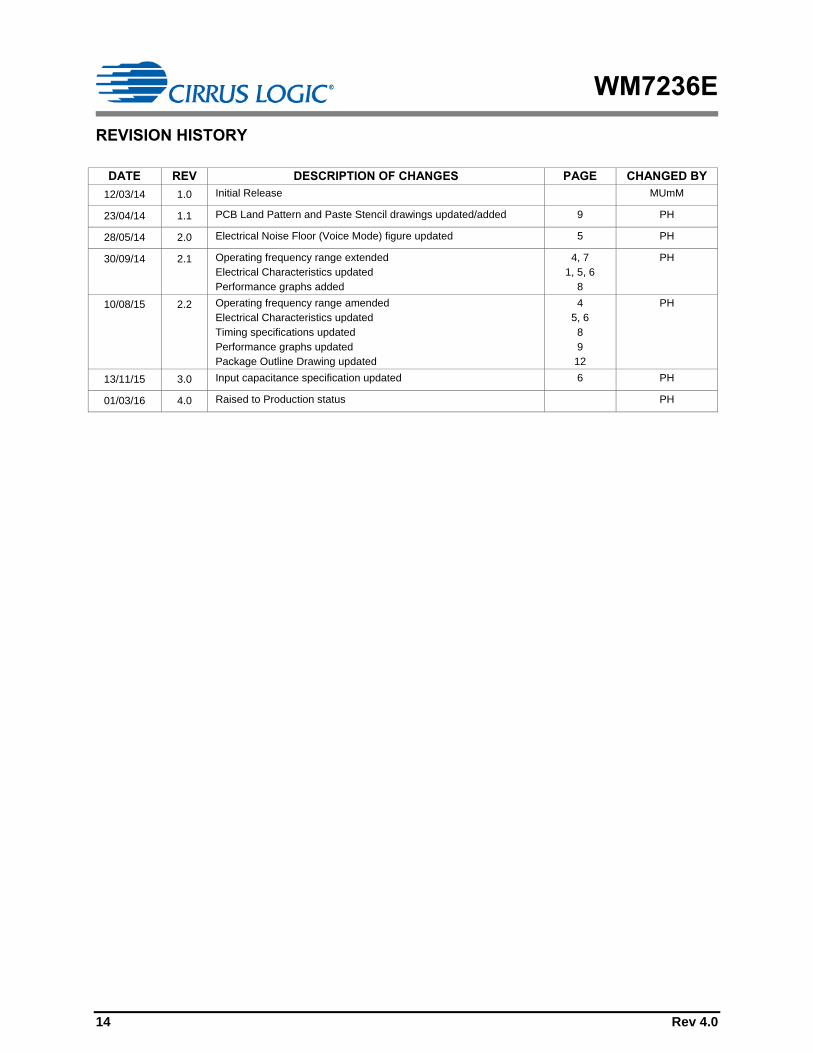
REVISION HISTORY
DATE REV DESCRIPTION OF CHANGES PAGE CHANGED BY
12/03/14 1.0 Initial Release MUmM
23/04/14 1.1 PCB Land Pattern and Paste Stencil drawings updated/added 9 PH
28/05/14 2.0 Electrical Noise Floor (Voice Mode) figure updated 5 PH
30/09/14 2.1 Operating frequency range extended
Electrical Characteristics updated
Performance graphs added
4, 7
1, 5, 6
8
PH
10/08/15 2.2 Operating frequency range amended
Electrical Characteristics updated
Timing specifications updated
Performance graphs updated
Package Outline Drawing updated
4
5, 6
8
9
12
PH
13/11/15 3.0 Input capacitance specification updated 6 PH
01/03/16 4.0 Raised to Production status PH