low-cost pole building construction
TRANSCRIPT
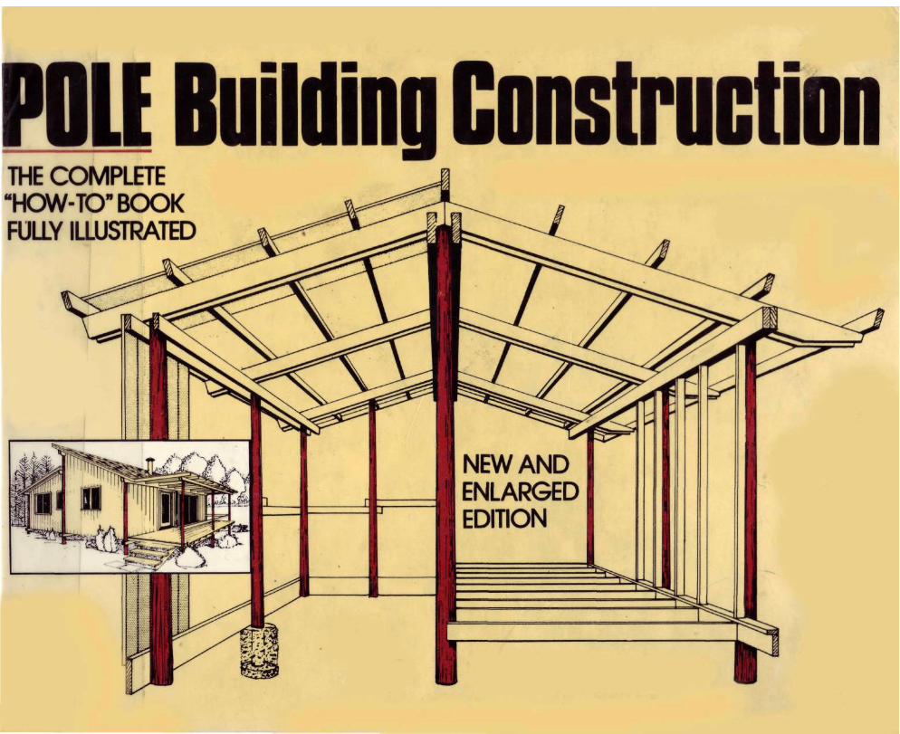
Advantages of Pole Construction
Many people are becoming interested in pole building construction because they have heard or read that it is relatively cheap and simple. It is, but to understand exactly what it's all about, we should start with a definition:
Pole construction is building in which the vertical, load-bearing members are poles embedded in the ground, and which must be long enough to support the roof. The diameter of the poles usually is about six inches at the top ends, and they are spaced much further apart than are the uprights in conventional frame construction. No excavation is necessary beyond digging holes for the poles, and there is no concrete or block foundation. The poles serve the triple function of foundation, bracing and framework, to which the floor (if any), walls and roof all are fastened.
Labor, time and materials all are saved in the pole framing method. Since lateral girts replace the conventional wall studs, and since fewer and longer pieces of lumber are used, the actual framework of the building can be completed quickly. This is a real advantage in bad weather, as the project can be placed under cover rapidly.
Pole buildings have been approved where light frame structures are prohibited because of fire hazard. Pole framing members are so widely separated that fire is unlikely to
spread from one to the other. Pole construction is now recognized by all four U.S. model building codes.
Other advantages of pole construction are: It is relatively simple to build, and little sawing is necessary. No scaffolding or forms are required during construction, and a minimum of construction labor is needed. In buildings where the loads are relatively light or the spans rather short, lower (hence cheaper) grades of lumber may be used. If the pole holes are dug by hand, only simple hand tools—the kind found in almost any household—are needed.
There are further advantages to this kind of construction in that round timbers have two distinct advantages from the standpoint of strength.
A circular timber is 18 per cent stronger in bending resistance than a rectangular timber of similar grade. A round timber, in practically all cases, possesses a very high proportion of the basic strength of its species. This is because the knots have only half the limiting effect on strength in the natural, round timber form that they do in sawed sections. Tests have shown that full-size round timber poles develop practically the full bending strength of clear wood.
Another advantage of pole frame construction is its high resistance to wind forces, which results because the poles that support the building are firmly anchored in the ground.
Later in this book general basic directions are given on how to construct a pole building, and these are followed by some specific plans. Right now it's enough to say that the poles are embedded in the ground, and they must be plumb.
The design of any pole building can be simple enough for unskilled persons to construct. Except for very small buildings, the step of setting the poles, however, is not a project for one person, the reason being that you have only two hands. For this step probably you should hire some
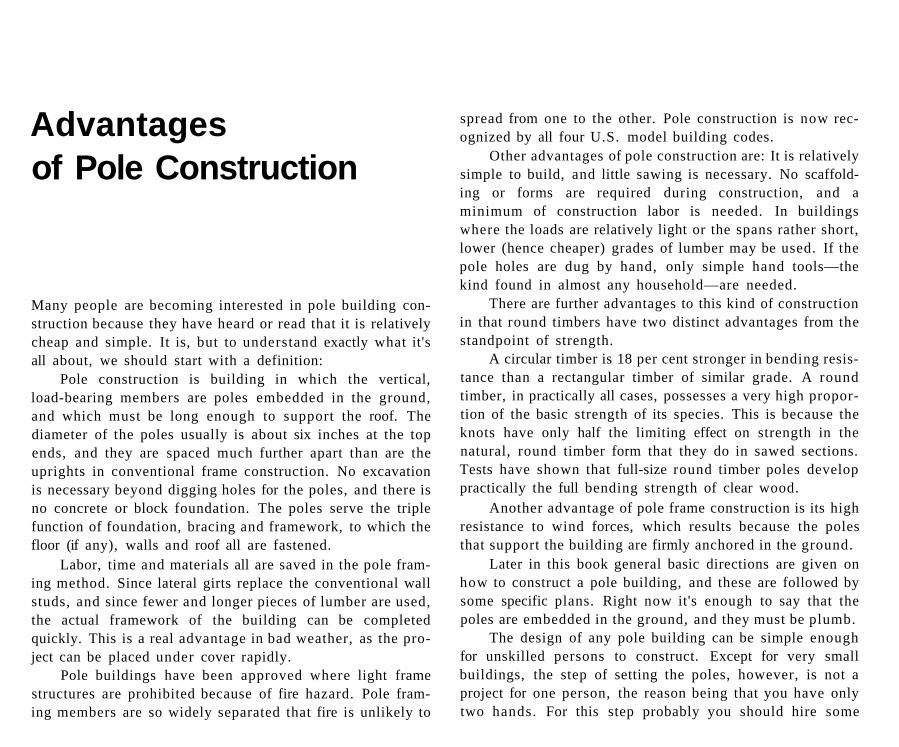
HOW IT GOES TOGETHER
Left side of this cutaway view shows embedment of poles, attachment of rafter plates, rafters, purlins and roofing. Below are the splashboards, girts and siding. The right side is for a more finished building, as indicated by floor plate and joists and wall framing inside the poles. Eaves are given more overhang.
unskilled help, which you will supervise, or maybe you can find neighborly help, or rent a machine to lift the poles.
In Vermont Life Magazine (Summer 1956 issue) there's a story of a pole-type barn-raising after a man's barn burned and his cattle were without shelter. Neighbors helped on the barn (the women cooked), and in two days the poles and main timbers of the new, 80-cow barn were secured, and the majority of the roof was in place.
Once the poles are plumb, the next step is to nail (or bolt) the longitudinal beams to the poles, and make sure the structure is squared up. The roof rafters are connected to this frame, and then your exterior is completed—not forgetting to put on a roof!
What kinds of buildings lend themselves to pole construction? The list is long and includes just about any type of commercial building, such as a warehouse or light manufacturing plant. Then there are farm buildings of all kinds—cow barns, horse barns, cattle sheds, poultry houses, tool sheds and the like. There are homes, too.
Prefabricated pole buildings for commercial and farm use are obtainable from several manufacturers. The purpose of this book, however, is to show you how you can do it yourself economically. Later some plans will be pictured in detail, and these will include houses.
It was said earlier that pole construction is relatively simple, but bear in mind the operative word here is "relatively." It would be cheating to give the impression it is as simple as making a sandbox for your youngster. But neither is it nearly as difficult (or expensive) as the conventional type of construction, which requires skilled labor, the extensive use of power tools, and more and costlier materials.
Pole building in varying forms is an age-old type of construction that dates back to the Stone Age.
Amos Rapoport in House Form and Culture says "There are cases where a way of life may lead to . . . a dwelling form related to economic activity rather than climate. For example, the Hidatsa of the Missouri valley were agriculturists from April to November, growing corn, greens and beans. During that period they lived in circular wooden houses 30 to 40 feet in diameter with 5-foot walls made of tree trunks and four central columns 14 feet high supporting rafters carrying branches."
Rapoport goes on to comment on resistance to lateral forces, such as wind or earthquakes, that requires either rigidity or bracing.
"The Fiji islands provide a number of examples of methods of dealing with the lateral force, problem. In some areas the roofs are very simple and supported by central poles as well as peripheral columns. Since these poles are buried deep in the ground, the building acts as a rigid frame, although the flexibility of the members themselves assures some flexibility."
In pole construction the poles actually have an inherent ability to resist wind uplift, especially if the roof framing is very securely attached to them. In areas where hurricanes are expected, the value of this large resistence to uplift that is a part of pole construction should be considered seriously.
Why is there so much current interest in pole construction? There seems to be a batch of good reasons:
1. A limited amount of grading is required, and no excavation beyond digging the pole holes. Thus it can be accomplished without butchering the immediate area, and with a minimum disturbance of the natural surroundings such as tree roots and top soil.
2. Pole construction offers a way to lower building costs by utilizing, if desired, steep hillside locations which
present many problems for more conventional construction. There are no delays, either, in waiting for cement foundations to cure, for there are none.
3. As inflation causes the costs of building materials and labor to climb, there is a very real need for many people to find ways to build more cheaply than before. Pole methods allow such savings.
4. Ever since World War II there has been an ever-increasing interest in self-help. Not only are there many practical advantages to "doing it yourself," but there is a very tangible glow of pride and satisfaction when one completes his own project.
5. With the back-to-the-land movement increasing every year, many people are rejecting expensive and conspicuous life styles. They want and have only the simple tools for living, and are choosing to live in many ways as their ancestors did.
All of this adds up to the reason why pole construction may be the very thing to plan on, whether it is for a home or some other building that you need.
Very little has been published to date on pole construction. In fact it has been said that "the literature is nonexistent." This is not quite true, for there are some few publications by wood products associations, which have been consulted here, and which are listed in the references at the back of this book.
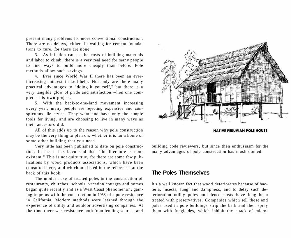
The modern use of treated poles in the construction of restaurants, churches, schools, vacation cottages and homes began quite recently and as a West Coast phenomenon, gain-ing impetus with the construction in 1958 of a pole residence in California. Modern methods were learned through the experience of utility and outdoor advertising companies. At the time there was resistance both from lending sources and
building code reviewers, but since then enthusiasm for the many advantages of pole construction has mushroomed.
The Poles Themselves
It's a well known fact that wood deteriorates because of bacteria, insects, fungi and dampness, and to delay such deterioration utility poles and fence posts have long been treated with preservatives. Companies which sell these and poles used in pole buildings strip the bark and then spray them with fungicides, which inhibit the attack of micro-
organisms. Then the poles are pressure-impregnated with one of several preservatives.
Such poles can be purchased rather inexpensively, or if you have suitable trees on your own land which can be cut into poles, you can surface-treat them yourself, or better, find a place (inquire at lumber yards) where they can be pressure-treated.
Soft woods are favored for treated poles because they are porous and accept preservatives better than do the hard woods. Also they are easier to work with in terms of nailing or sawing.
Woods listed as approved for poles to be treated include Western larch. Southern yellow pine. Pacific Coast Douglas fir, lodgepole pine, jack pine, red or Norway pine, Ponderosa pine. Western red cedar and Northern white cedar. White pine also is used in the East, as are white and red spruce.
However, if you have a ready access to white or red cedar, locust, redwood heart or cypress, the poles made from these woods will be inherently resistant to rot and micro-organisms. Hemlock also is rot-resistant but is more often used as lumber. These woods need not be pressure-treated, but should have the bark removed.
How long will poles last before deteriorating? This is important, since the poles are the foundation and strength of the structure.
There are varying answers. One firm which manufactures treated poles says: 'In the Thirties a well-treated pole was supposed to last 30 years. Now this estimate has risen to 45 to 50 years, since anticipated failures did not occur. The length of service has been achieved under the most severe
conditions. Of course, any pole which you use inside your building will be protected, and an even longer life can be expected."
The American Wood Preservers Institute, conducting research for the Department of Housing and Urban Development, prepared the booklet FHA Pole House Construction, which sets forth guidelines acceptable to FHA for the construction of pole houses.
The AWPI is a non-profit organization doing research on pressure-treated woods of all kinds for all uses. Their comments on the durability of poles are especially valuable, although their standards are- so high that not all manufacturers fully meet them.
AWPI says: "A house erected on poles produced for this purpose, and conforming to the rigid standards described below, is considered permanent—as permanent as a house on a well-constructed concrete foundation. The permanence is achieved by treating the poles with preservative. Using the newly-perfected 'assay method', pole manufacturers now can verify the adequate distribution of preservative in the finished product."
The assay testing method takes borings from the treated poles and subjects them to chemical analysis to determine the amount of preservative present.
AWPI goes on to say that "Users can be assured of the physical and preservative characteristics of the poles if the manufacturer indicates conformance with the AWPI quality control standards by the application of a permanent seal to each pole."
Although all the preservative treatments have their uses in pole construction, cleanliness, paintability, color and odor will determine the selection for a particular project. The methods are:
Water-borne salt preservatives: They provide clean, odorless, paintable, non-irritating pressure-treated lumber. For poles placed in the ground and subject to leaching, one should be sure to have that treatment which is chemically-bound—not that which is leachable. Recommended by the American Society of Civil Engineers are amoniacal copper arsenite, chromated copper arsenate or chromated zinc arsenate.
Pentachlorophenol in light petroleum solvent: The pole surface is comparatively clean and usually can be painted, provided the wood preserver knows prior to treatment that this is desired. There may be a slight odor until the petroleum has vaporized. This treatment has little effect on the color of the wood.
Pentachlorophenol in volatile petroleum solvent (gas-home treatment): The wood surface also is clean, paintable and odorless, with its color that of the natural wood prior to treatment.
Creosote: The color varies from dark brown to black and the surface often is oily, especially when subjected to higher temperatures. Successful painting is impossible. These factors, plus the creosote odor, make these poles more suitable for use on the exterior of pole buildings. It should be noted
that vegetation in direct contact with these poles will be killed for a year or two. Poles so treated are widely used throughout the United States by utility companies and are readily available.
Pentachlorophenol in heavy oil: The pole often has an oily surface, particularly when high temperatures cause an expansion of the liquid petroleum. Pole varies in color from light to dark brown, and an odor usually is present for a period of time. It is often difficult, if not impossible, to paint these poles successfully. Poles treated with this preservative also are readily available, since this too is a common treatment for utility use.
Preservative oils, creosote and the liquid pentachlorophenol petroleum solutions used on poles sometimes travel from the treated wood along nails, and will discolor adjacent plaster or finished flooring. Oil types, however, have a maximum service life.
Tar solutions applied to poles do not penetrate and preserve the wood. The protection offered, is temporary.
Cuts, such as notches or holes drilled through the preservative zone, should receive several liberal applications of wood preservative to retain the chemical integrity of the pole.
Home-Treatment of Poles and Skirting
Home builders who are unable to secure pressure-treated poles and skirting boards or find the costs prohibitive, can treat poles themselves using one of the newer methods developed at the U.S. Forest Products Laboratory.
The processes consist of soaking the green, undried wood first in one chemical solution and then in a second one. The two chemicals diffuse into the wet wood and then react with each other to form -a compound that is poisonous to termites and to the fungi which cause rot. Moreover, the bonded chemicals are practically insoluble in water, and therefore do not leach out to any appreciable extent when the poles are used in moist soils. Some species of wood are more receptive to this treatment method (see page 12), and tests show that hardwoods are less receptive than the softwoods as a class.
Several combinations of chemicals may be used in this home-treatment process, but the instructions given here employ materials more commonly stocked by chemical dealers.
About 25 pounds of technical (industrial grade) copper sulphate will be needed to treat 10 posts of average size, together with about 121/2 pounds of technical sodium fluoride. Local farm supply and hardware stores may have to order for you from chemical supply houses, and the costs
will vary according to quantity needed and shipping distances.
Because the solutions used here are harmful, great care should be exercised in handling the dry powders and the dissolved chemicals too. When working with the materials it is best to use goggles, rubber gloves and to avoid breathing the poisonous vapors and dust. If the chemicals should get on the skin or eyes, they should be washed out quickly. Clothes that are splashed by the chemicals should be rinsed in clear water and not washed with other clothing.
Treatment of your poles should start as soon as possible after they are cut—preferably within a week, or they will be too dry to accept the chemicals effectively. After cutting, pile the poles as closely as possible together and if available cover with a tarpaulin. Just before they are placed in the solution the poles should be trimmed six inches at each end and peeled of bark.
Preparation of the Solutions
The chemicals can be weighed out or measured in a one-pound size coffee can, which will hold about two pounds of chemicals.
The containers or pits (see illustrations) will be needed, one to hold each of the separate solutions. Copper sulphate is corrosive to iron, so if a drum is used it should be coated inside with pitch (heavy roofing tar) or lined with heavy polyethylene film.
The sodium fluoride solution is prepared in a proportion of three gallons of water to one pound of the chemical. The amount needed will depend upon the size of the container or pit used. Stir the solution well. Place the poles—as many as
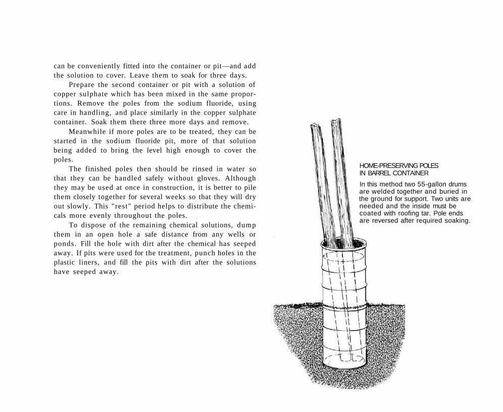
can be conveniently fitted into the container or pit—and add the solution to cover. Leave them to soak for three days.
Prepare the second container or pit with a solution of copper sulphate which has been mixed in the same proportions. Remove the poles from the sodium fluoride, using care in handling, and place similarly in the copper sulphate container. Soak them there three more days and remove.
Meanwhile if more poles are to be treated, they can be started in the sodium fluoride pit, more of that solution being added to bring the level high enough to cover the poles.
The finished poles then should be rinsed in water so that they can be handled safely without gloves. Although they may be used at once in construction, it is better to pile them closely together for several weeks so that they will dry out slowly. This "rest" period helps to distribute the chemicals more evenly throughout the poles.
To dispose of the remaining chemical solutions, dump them in an open hole a safe distance from any wells or ponds. Fill the hole with dirt after the chemical has seeped away. If pits were used for the treatment, punch holes in the plastic liners, and fill the pits with dirt after the solutions have seeped away.
HOME-PRESERVING POLES IN BARREL CONTAINER
In this method two 55-gallon drums are welded together and buried in the ground for support. Two units are needed and the inside must be coated with roofing tar. Pole ends are reversed after required soaking.
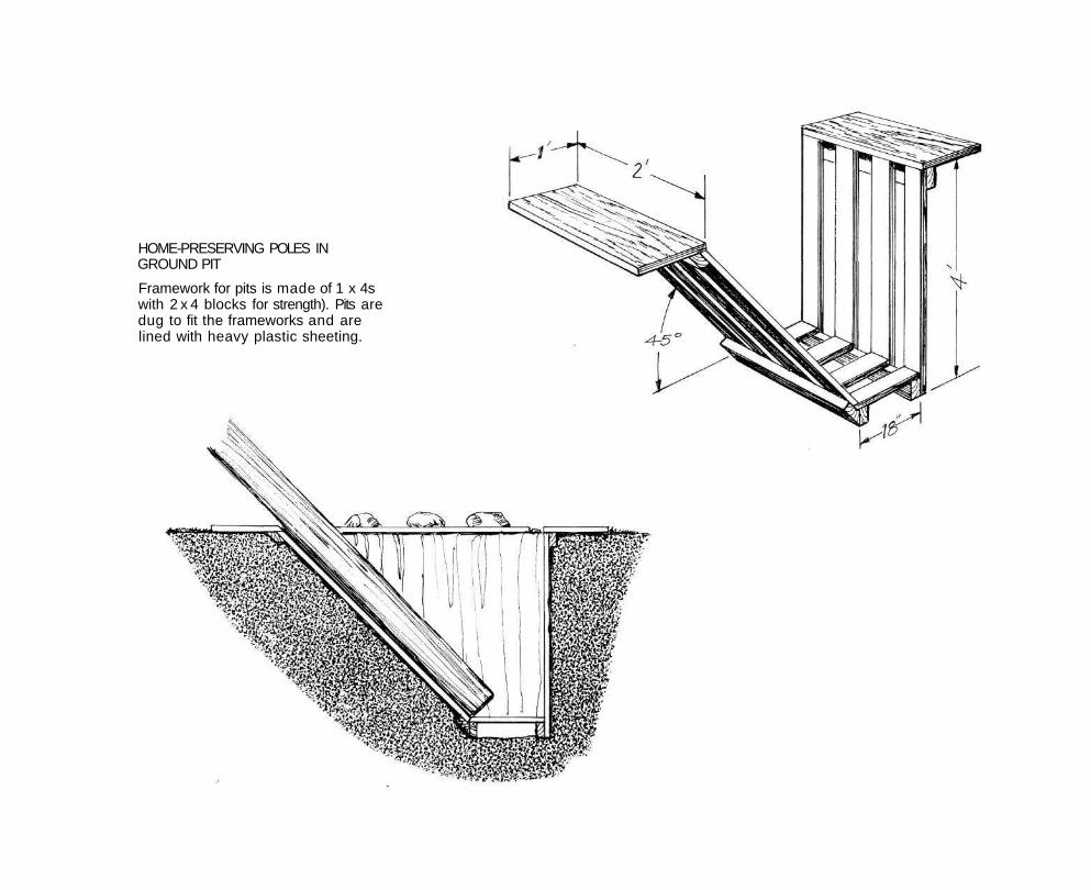
HOME-PRESERVING POLES IN GROUND PIT
Framework for pits is made of 1 x 4s with 2 x 4 blocks for strength). Pits are dug to fit the frameworks and are lined with heavy plastic sheeting.
The Fastenings to Use
The fastening used in pole construction may be limited to nails and spikes, or include also bolts or lag screws or even patented special fasteners. The choice usually will depend upon costs and availability as well as the labor factors involved.
At framing areas where side stress might be expected, the use of bolts or lag screws should give rigidity superior to spikes or special fasteners.
Nails & Bolts: For all practical purposes there is no difference in the shearing strength of bolts, lag screws or spikes, providing the total diameters are about the same. For exam
ple, three 60d spikes, which have a diameter of 5/16 inch, will equal the strength of a 3/4-inch bolt, where the load on these fastenings is primarily vertical. As an assurance against spikes working loose, use cement-coated spikes or "barn spikes", which have a screw-like shank.
The choice of fasteners lies primarily in which is easier for you. Lead holes should be drilled for spikes, particularly near the ends of planks, to prevent splitting. This can be done on the ground, whereas holes for bolts that go through the poles must be drilled after the poles have been erected.
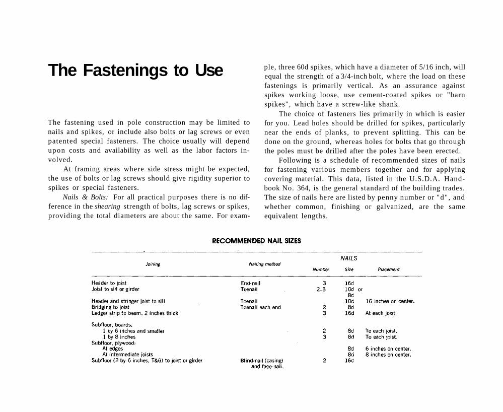
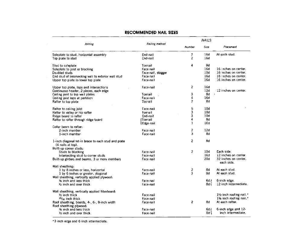
Following is a schedule of recommended sizes of nails for fastening various members together and for applying covering material. This data, listed in the U.S.D.A. Handbook No. 364, is the general standard of the building trades. The size of nails here are listed by penny number or "d", and whether common, finishing or galvanized, are the same equivalent lengths.
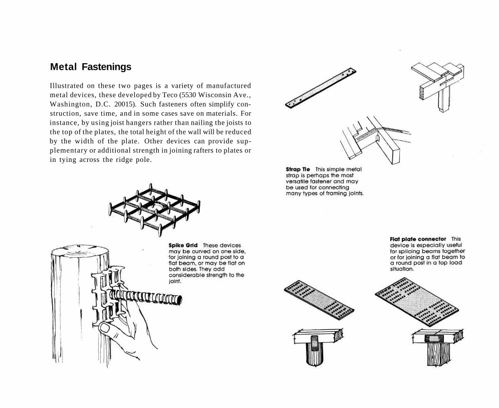
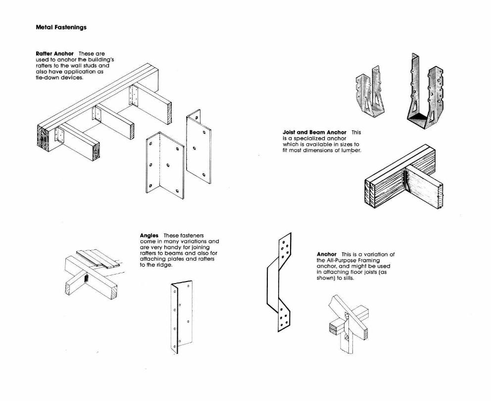
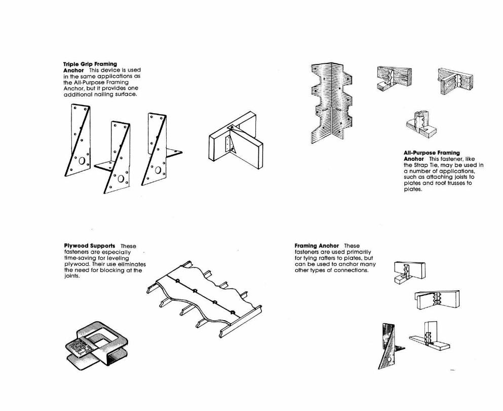
Metal Fastenings
Illustrated on these two pages is a variety of manufactured metal devices, these developed by Teco (5530 Wisconsin Ave., Washington, D.C. 20015). Such fasteners often simplify construction, save time, and in some cases save on materials. For instance, by using joist hangers rather than nailing the joists to the top of the plates, the total height of the wall will be reduced by the width of the plate. Other devices can provide supplementary or additional strength in joining rafters to plates or in tying across the ridge pole.

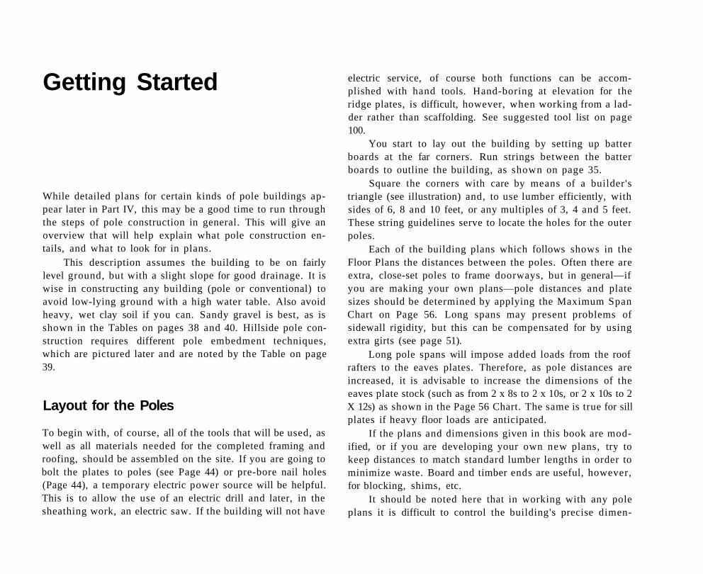
Getting Started
While detailed plans for certain kinds of pole buildings appear later in Part IV, this may be a good time to run through the steps of pole construction in general. This will give an overview that will help explain what pole construction entails, and what to look for in plans.
This description assumes the building to be on fairly level ground, but with a slight slope for good drainage. It is wise in constructing any building (pole or conventional) to avoid low-lying ground with a high water table. Also avoid heavy, wet clay soil if you can. Sandy gravel is best, as is shown in the Tables on pages 38 and 40. Hillside pole construction requires different pole embedment techniques, which are pictured later and are noted by the Table on page 39.
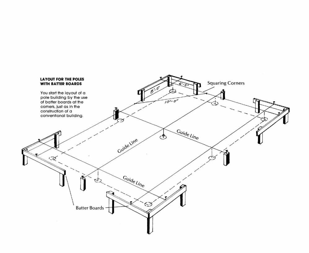
Layout for the Poles
To begin with, of course, all of the tools that will be used, as well as all materials needed for the completed framing and roofing, should be assembled on the site. If you are going to bolt the plates to poles (see Page 44) or pre-bore nail holes (Page 44), a temporary electric power source will be helpful. This is to allow the use of an electric drill and later, in the sheathing work, an electric saw. If the building will not have
electric service, of course both functions can be accomplished with hand tools. Hand-boring at elevation for the ridge plates, is difficult, however, when working from a ladder rather than scaffolding. See suggested tool list on page 100.
You start to lay out the building by setting up batter boards at the far corners. Run strings between the batter boards to outline the building, as shown on page 35.
Square the corners with care by means of a builder's triangle (see illustration) and, to use lumber efficiently, with sides of 6, 8 and 10 feet, or any multiples of 3, 4 and 5 feet. These string guidelines serve to locate the holes for the outer poles.
Each of the building plans which follows shows in the Floor Plans the distances between the poles. Often there are extra, close-set poles to frame doorways, but in general—if you are making your own plans—pole distances and plate sizes should be determined by applying the Maximum Span Chart on Page 56. Long spans may present problems of sidewall rigidity, but this can be compensated for by using extra girts (see page 51).
Long pole spans will impose added loads from the roof rafters to the eaves plates. Therefore, as pole distances are increased, it is advisable to increase the dimensions of the eaves plate stock (such as from 2 x 8s to 2 x 10s, or 2 x 10s to 2 X 12s) as shown in the Page 56 Chart. The same is true for sill plates if heavy floor loads are anticipated.
If the plans and dimensions given in this book are modified, or if you are developing your own new plans, try to keep distances to match standard lumber lengths in order to minimize waste. Board and timber ends are useful, however, for blocking, shims, etc.
It should be noted here that in working with any pole plans it is difficult to control the building's precise dimen-
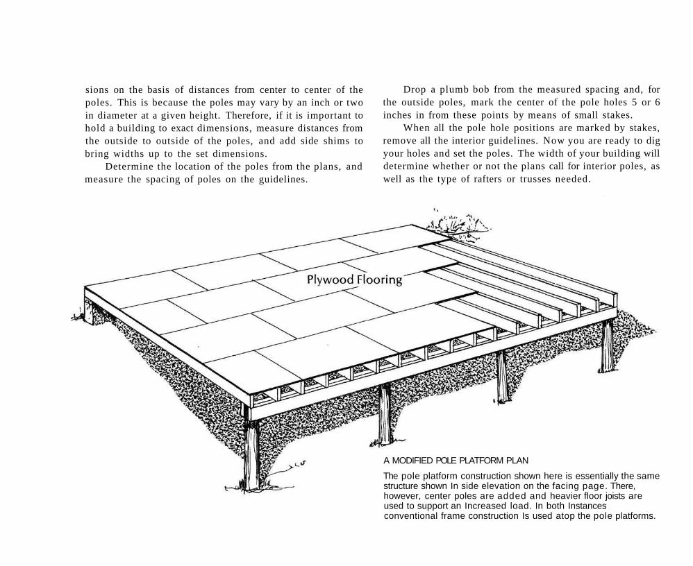
sions on the basis of distances from center to center of the poles. This is because the poles may vary by an inch or two in diameter at a given height. Therefore, if it is important to hold a building to exact dimensions, measure distances from the outside to outside of the poles, and add side shims to bring widths up to the set dimensions.
Determine the location of the poles from the plans, and measure the spacing of poles on the guidelines.
Drop a plumb bob from the measured spacing and, for the outside poles, mark the center of the pole holes 5 or 6 inches in from these points by means of small stakes.
When all the pole hole positions are marked by stakes, remove all the interior guidelines. Now you are ready to dig your holes and set the poles. The width of your building will determine whether or not the plans call for interior poles, as well as the type of rafters or trusses needed.
A MODIFIED POLE PLATFORM PLAN
The pole platform construction shown here is essentially the same structure shown In side elevation on the facing page. There, however, center poles are added and heavier floor joists are used to support an Increased load. In both Instances conventional frame construction Is used atop the pole platforms.
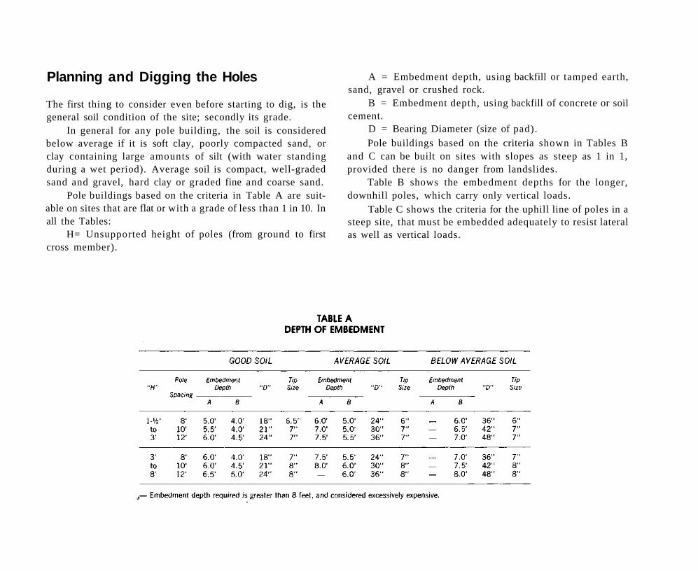
Planning and Digging the Holes
The first thing to consider even before starting to dig, is the general soil condition of the site; secondly its grade.
In general for any pole building, the soil is considered below average if it is soft clay, poorly compacted sand, or clay containing large amounts of silt (with water standing during a wet period). Average soil is compact, well-graded sand and gravel, hard clay or graded fine and coarse sand.
Pole buildings based on the criteria in Table A are suitable on sites that are flat or with a grade of less than 1 in 10. In all the Tables:
H= Unsupported height of poles (from ground to first cross member).
A = Embedment depth, using backfill or tamped earth, sand, gravel or crushed rock.
B = Embedment depth, using backfill of concrete or soil cement.
D = Bearing Diameter (size of pad). Pole buildings based on the criteria shown in Tables B
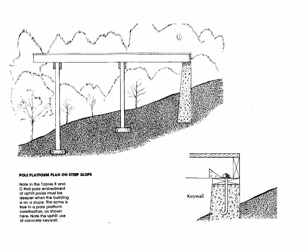
and C can be built on sites with slopes as steep as 1 in 1, provided there is no danger from landslides.
Table B shows the embedment depths for the longer, downhill poles, which carry only vertical loads.
Table C shows the criteria for the uphill line of poles in a steep site, that must be embedded adequately to resist lateral as well as vertical loads.
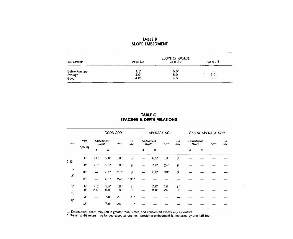
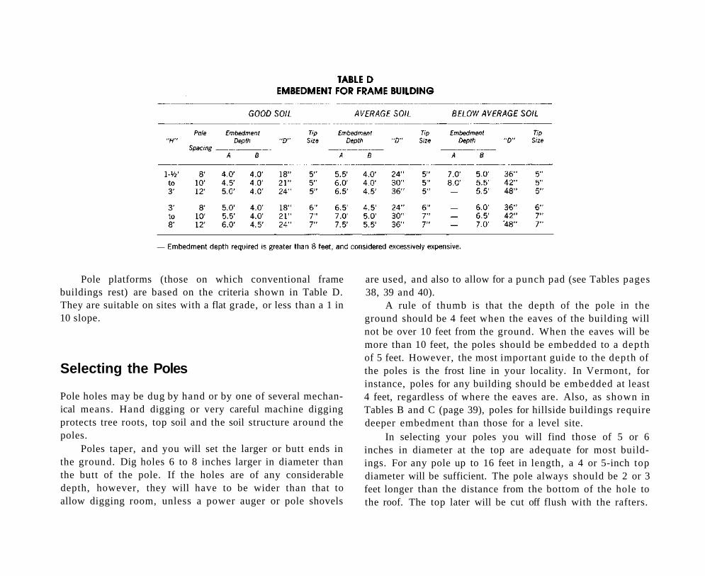
Pole platforms (those on which conventional frame buildings rest) are based on the criteria shown in Table D. They are suitable on sites with a flat grade, or less than a 1 in 10 slope.
Selecting the Poles
Pole holes may be dug by hand or by one of several mechanical means. Hand digging or very careful machine digging protects tree roots, top soil and the soil structure around the poles.
Poles taper, and you will set the larger or butt ends in the ground. Dig holes 6 to 8 inches larger in diameter than the butt of the pole. If the holes are of any considerable depth, however, they will have to be wider than that to allow digging room, unless a power auger or pole shovels
are used, and also to allow for a punch pad (see Tables pages 38, 39 and 40).
A rule of thumb is that the depth of the pole in the ground should be 4 feet when the eaves of the building will not be over 10 feet from the ground. When the eaves will be more than 10 feet, the poles should be embedded to a depth of 5 feet. However, the most important guide to the depth of the poles is the frost line in your locality. In Vermont, for instance, poles for any building should be embedded at least 4 feet, regardless of where the eaves are. Also, as shown in Tables B and C (page 39), poles for hillside buildings require deeper embedment than those for a level site.
In selecting your poles you will find those of 5 or 6 inches in diameter at the top are adequate for most buildings. For any pole up to 16 feet in length, a 4 or 5-inch top diameter will be sufficient. The pole always should be 2 or 3 feet longer than the distance from the bottom of the hole to the roof. The top later will be cut off flush with the rafters.
Setting and Aligning the Poles
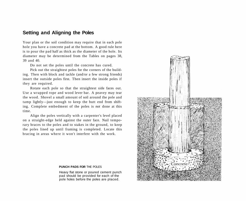
Your plan or the soil condition may require that in each pole hole you have a concrete pad at the bottom. A good rule here is to pour the pad half as thick as the diameter of the hole. Its diameter may be determined from the Tables on pages 38, 39 and 40.
Do not set the poles until the concrete has cured. Pick out the straightest poles for the corners of the build
ing. Then with block and tackle (and/or a few strong friends) insert the outside poles first. Then insert the inside poles if they are required.
Rotate each pole so that the straightest side faces out. Use a wrapped rope and wood lever bar. A peavey may tear the wood. Shovel a small amount of soil around the pole and tamp lightly—just enough to keep the butt end from shifting. Complete embedment of the poles is not done at this time.
Align the poles vertically with a carpenter's level placed on a straight-edge held against the outer face. Nail temporary braces to the poles and to stakes in the ground, to keep the poles lined up until framing is completed. Locate this bracing in areas where it won't interfere with the work.
PUNCH PADS FOR THE POLES
Heavy flat stone or poured cement punch pad should be provided for each of the pole holes before the poles are placed.
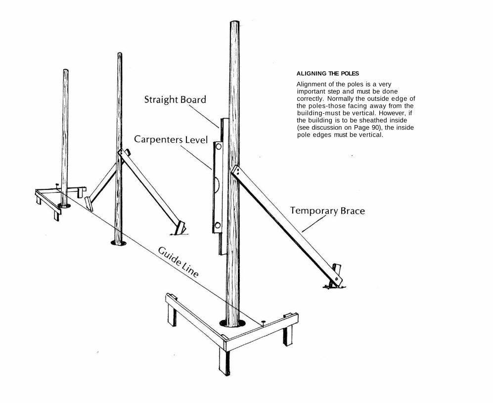
ALIGNING THE POLES
Alignment of the poles is a very important step and must be done correctly. Normally the outside edge of the poles-those facing away from the building-must be vertical. However, if the building is to be sheathed inside (see discussion on Page 90), the inside pole edges must be vertical.
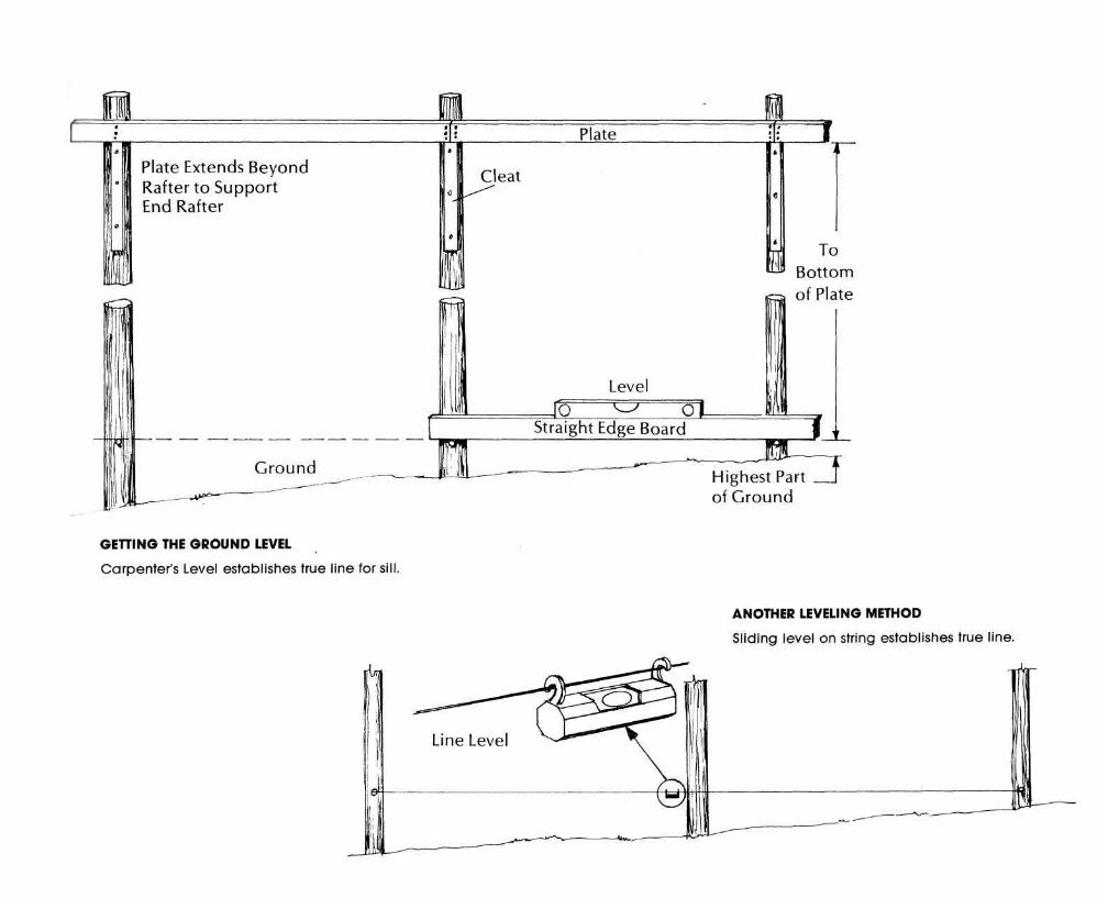
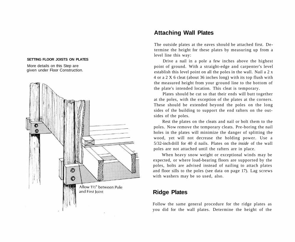
Attaching Wall Plates
The outside plates at the eaves should be attached first. Determine the height for these plates by measuring up from a level line this way:
Drive a nail in a pole a few inches above the highest point of ground. With a straight-edge and carpenter's level establish this level point on all the poles in the wall. Nail a 2 x 4 or a 2 X 6 cleat (about 36 inches long) with its top flush with the measured height from your ground line to the bottom of the plate's intended location. This cleat is temporary.
Plates should be cut so that their ends will butt together at the poles, with the exception of the plates at the corners. These should be extended beyond the poles on the long sides of the building to support the end rafters on the out-sides of the poles.
Rest the plates on the cleats and nail or bolt them to the poles. Now remove the temporary cleats. Pre-boring the nail holes in the plates will minimize the danger of splitting the wood, yet will not decrease the holding power. Use a 5/32-inch drill for 40 d nails. Plates on the inside of the wall poles are not attached until the rafters are in place.
When heavy snow weight or exceptional winds may be expected, or where load-bearing floors are supported by the poles, bolts are advised instead of nailing to attach plates and floor sills to the poles (see data on page 17). Lag screws with washers may be so used, also.
Ridge Plates
Follow the same general procedure for the ridge plates as you did for the wall plates. Determine the height of the
SETTING FLOOR JOISTS ON PLATES
More details on this Step are given under Floor Construction.
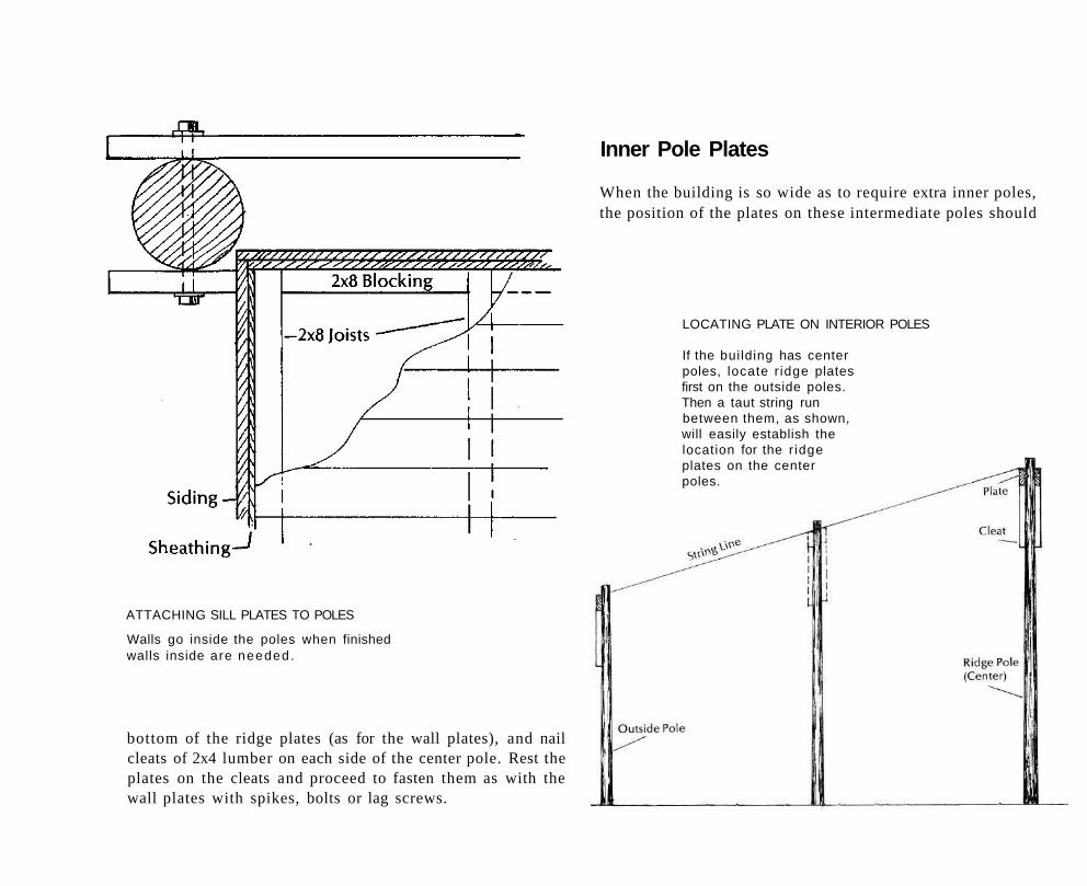
ATTACHING SILL PLATES TO POLES
Walls go inside the poles when finished walls inside are needed.
bottom of the ridge plates (as for the wall plates), and nail cleats of 2x4 lumber on each side of the center pole. Rest the plates on the cleats and proceed to fasten them as with the wall plates with spikes, bolts or lag screws.
LOCATING PLATE ON INTERIOR POLES
If the building has center poles, locate r idge plates first on the outside poles. Then a taut string run between them, as shown, will easily establish the location for the r idge plates on the center poles.
Inner Pole Plates
When the building is so wide as to require extra inner poles, the position of the plates on these intermediate poles should
be located by running a line from the ridge plate to the wall plate. Attach cleats and plates on both sides to correspond with this line.
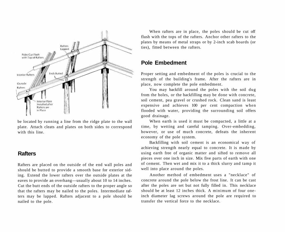
Rafters
Rafters are placed on the outside of the end wall poles and should be butted to provide a smooth base for exterior siding. Extend the lower rafters over the outside plates at the eaves to provide an overhang—usually about 10 to 14 inches. Cut the butt ends of the outside rafters to the proper angle so that the rafters may be nailed to the poles. Intermediate rafters may be lapped. Rafters adjacent to a pole should be nailed to the pole.
When rafters are in place, the poles should be cut off flush with the tops of the rafters. Anchor other rafters to the plates by means of metal straps or by 2-inch scab boards (or ties), fitted between the rafters.
Pole Embedment
Proper setting and embedment of the poles is crucial to the strength of the building's frame. After the rafters are in place, now complete the pole embedment.
You may backfill around the poles with the soil dug from the holes, or the backfilling may be done with concrete, soil cement, pea gravel or crushed rock. Clean sand is least expensive and achieves 100 per cent compaction when flooded with water, providing the surrounding soil offers good drainage.
When earth is used it must be compacted, a little at a time, by wetting and careful tamping. Over-embedding, however, or use of much concrete, defeats the inherent economy of the pole system.
Backfilling with soil cement is an economical way of achieving strength nearly equal to concrete. It is made by using earth free of organic matter and sifted to remove all pieces over one inch in size. Mix five parts of earth with one of cement. Then wet and mix it to a thick slurry and tamp it well into place around the poles.
Another method of embedment uses a "necklace" of concrete around the pole below the frost line. It can be cast after the poles are set but not fully filled in. This necklace should be at least 12 inches thick. A minimum of four one-inch diameter lag screws around the pole are required to transfer the vertical force to the necklace.
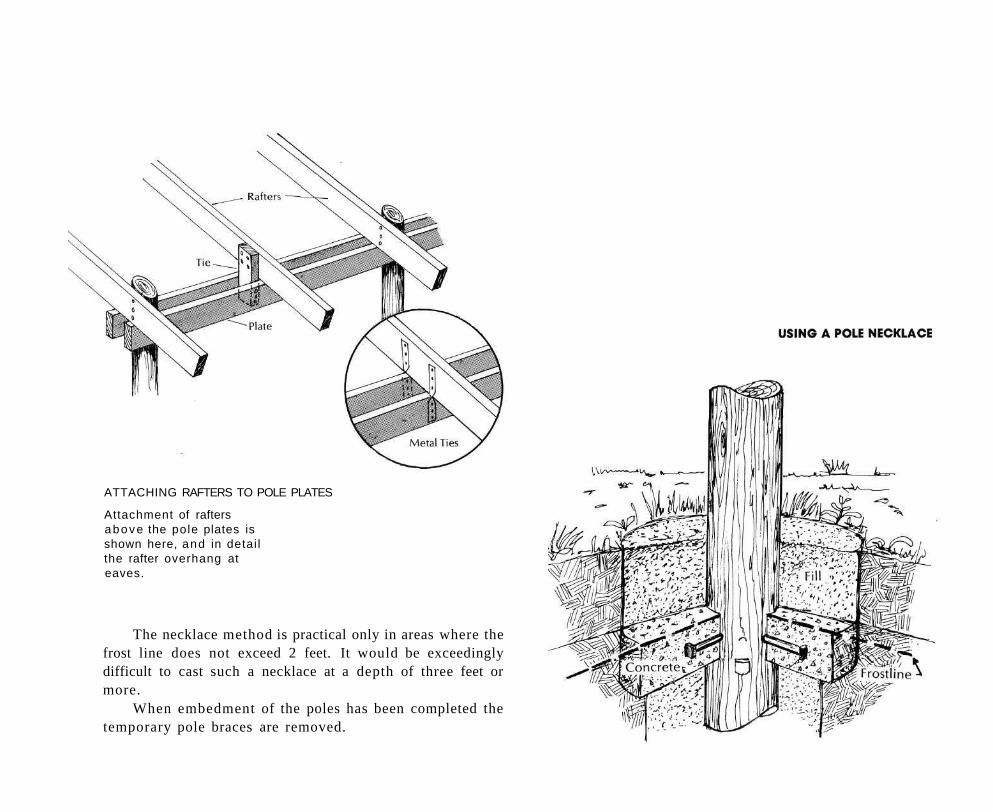
ATTACHING RAFTERS TO POLE PLATES
Attachment of rafters above the pole plates is shown here, and in detai l the rafter overhang at eaves.
The necklace method is practical only in areas where the frost line does not exceed 2 feet. It would be exceedingly difficult to cast such a necklace at a depth of three feet or more.
When embedment of the poles has been completed the temporary pole braces are removed.
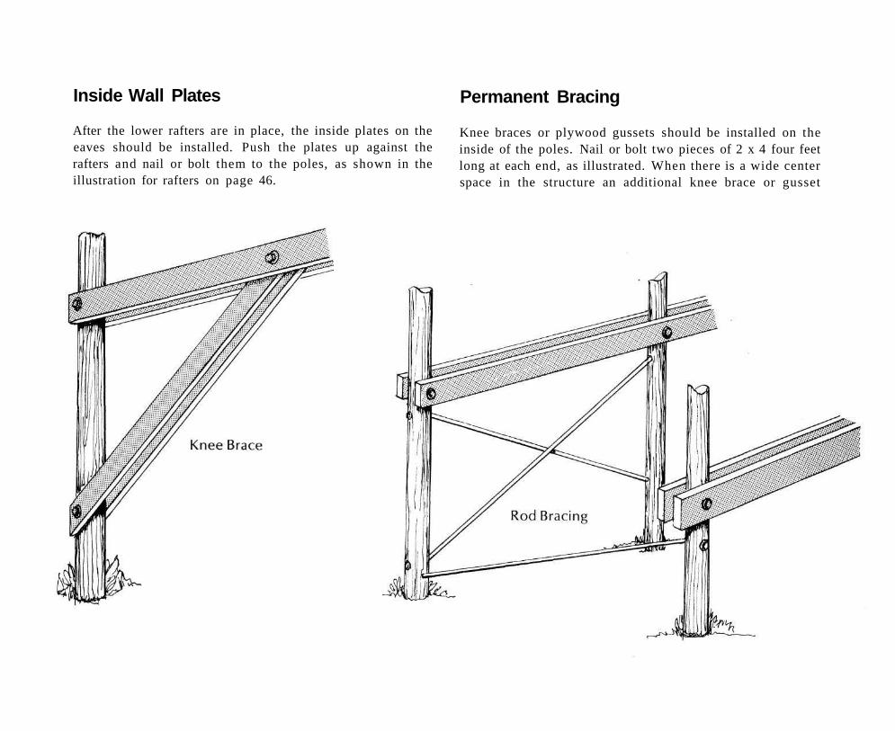
Inside Wall Plates
After the lower rafters are in place, the inside plates on the eaves should be installed. Push the plates up against the rafters and nail or bolt them to the poles, as shown in the illustration for rafters on page 46.
Permanent Bracing
Knee braces or plywood gussets should be installed on the inside of the poles. Nail or bolt two pieces of 2 x 4 four feet long at each end, as illustrated. When there is a wide center space in the structure an additional knee brace or gusset
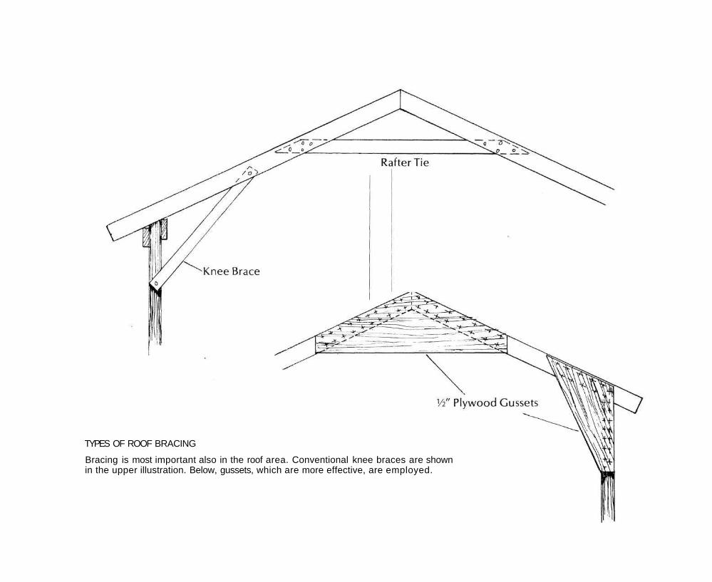
TYPES OF ROOF BRACING
Bracing is most important also in the roof area. Conventional knee braces are shown in the upper illustration. Below, gussets, which are more effective, are employed.
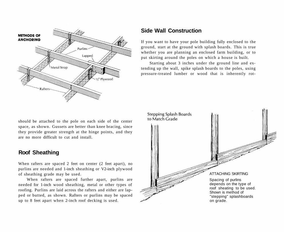
Side Wall Construction
If you want to have your pole building fully enclosed to the ground, start at the ground with splash boards. This is true whether you are planning an enclosed farm building, or to put skirting around the poles on which a house is built.
Starting about 3 inches under the ground line and extending up the wall, spike splash boards to the poles, using pressure-treated lumber or wood that is inherently rot-
should be attached to the pole on each side of the center space, as shown. Gussets are better than knee bracing, since they provide greater strength at the hinge points, and they are no more difficult to cut and install.
Roof Sheathing
When rafters are spaced 2 feet on center (2 feet apart), no purlins are needed and 1-inch sheathing or V2-inch plywood of sheathing grade may be used.
When rafters are spaced further apart, purlins are needed for 1-inch wood sheathing, metal or other types of roofing. Purlins are laid across the rafters and either are lapped or butted, as shown. Rafters or purlins may be spaced up to 8 feet apart when 2-inch roof decking is used.
ATTACHING SKIRTING
Spacing of purlins depends on the type of roof sheating to be used. Shown is method of "stepping" splashboards on grade.
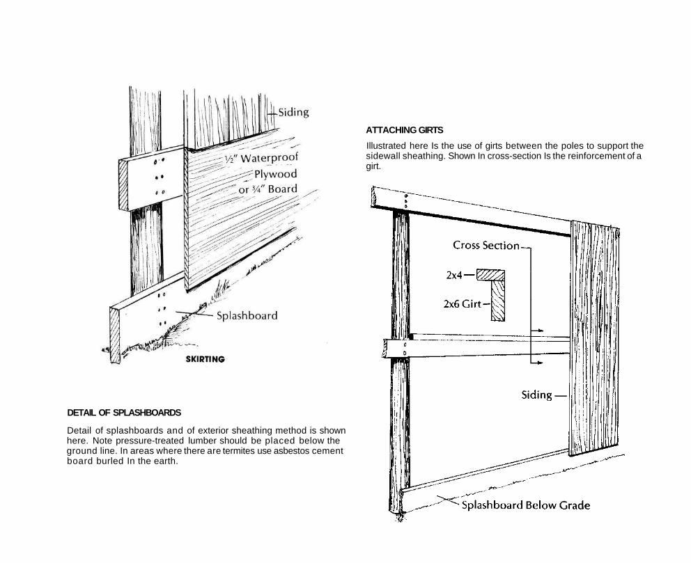
DETAIL OF SPLASHBOARDS
Detail of splashboards and of exterior sheathing method is shown here. Note pressure-treated lumber should be placed below the ground line. In areas where there are termites use asbestos cement board burled In the earth.
ATTACHING GIRTS
Illustrated here Is the use of girts between the poles to support the sidewall sheathing. Shown In cross-section Is the reinforcement of a girt.
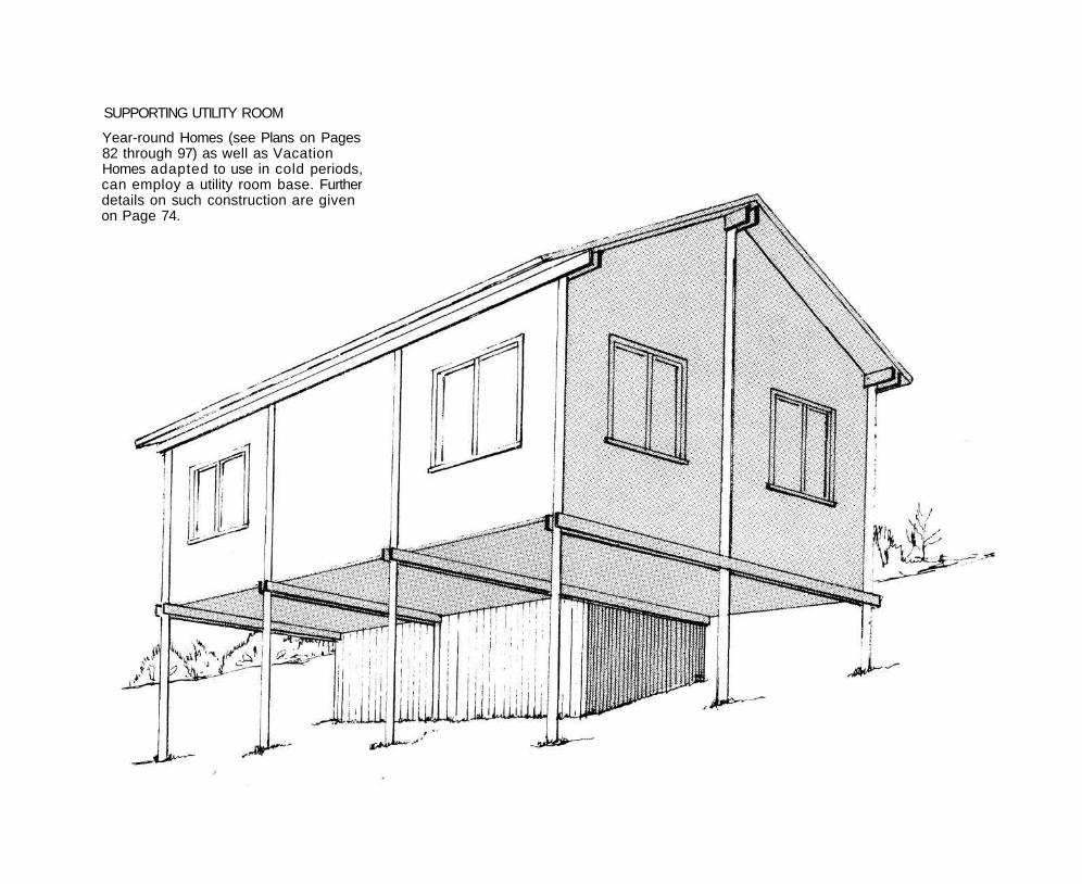
SUPPORTING UTILITY ROOM
Year-round Homes (see Plans on Pages 82 through 97) as well as Vacation Homes adapted to use in cold periods, can employ a utility room base. Further details on such construction are given on Page 74.
resistant (see page 12). These should be one or two 2 x 10 or 2 X 12 planks.
Girts for the siding are nailed across the poles above the splash boards. They should be spaced on 2 feet or 4 feet, depending upon the type of siding to be used. Generally speaking, metal siding will require 2-foot centers, while wood can be on 4-foot centers.
If the space between poles exceeds 6 feet, a 2 x 4 is placed (as illustrated) on each 2 x 6 for reinforcement. However, metal siding always will require more reinforcing than wood.
Vertical boards and battens (or other kinds of siding such as plywood or metal) then are attached to the girts. In any case, the top two inches of the splash boards should be overlapped by the side walls.
Reinforced girts usually provide adequate sidewall rigidity when spaced as close as two feet apart. Placement of vertical studs, toe-nailed to sill and eaves plates, will be used where windows interrupt the girts. Windows and exterior doors should be framed in with wall studs in any event.
Studs perform no weight-support role for either roof or floor, however, in pole construction. Safe pole distances and adequately heavy eaves and floor plates do it all.
Floor Construction and Insulation
Most pole buildings, unless a dirt floor is in order, will have a slab floor (see bottom illustration on Page 54) or a suspended floor, and if these buildings are to be located and used in cold climate areas, construction should be planned with the view to effective floor insulation. Methods of suspended floor joist attachment are shown on Page 53, while
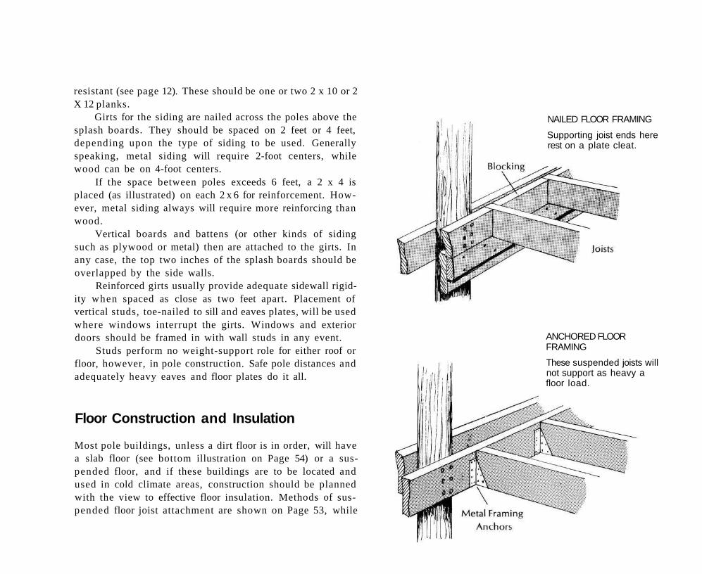
ANCHORED FLOOR FRAMING
These suspended joists will not support as heavy a floor load.
NAILED FLOOR FRAMING
Supporting joist ends here rest on a plate cleat.
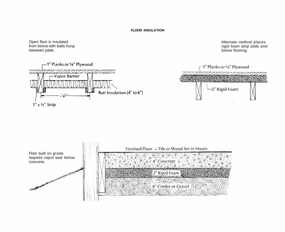
FLOOR INSULATION
Alternate method places rigid foam atop joists and below flooring.
Floor built on grade requires vapor seal below concrete.
Open floor is insulated from below with batts hung between joists.
those which are illustrated on Page 44 will provide for greater floor loading. The chart on Page 56 provides safe formulae of load and support for both floors and roofs. In cold country take into account the weight of possible snow accumulations, particularly if the roof pitch is shallow.
In slab floor construction do not overlook the need to lay a vapor barrier of polyethylene sheeting under the slab. Otherwise the slab will absorb ground moisture, and some serious problems may develop later.
In climates where termites occur, ring cups may be placed around the poles and the wall skirting is not run down to the ground level.
Framing for Floors
Floors carrying heavy leads (see chart Page 56) will be stronger if supported by bolt or lag screw attachment, as shown on Page 44. The butting of joists to the sill plates, attached with metal strapping, as shown, would not be used except where light floor loads are planned. The overlapped joists rest on and are supported by the sill plates, and will have a greater load capacity.
Floor Insulation
Methods of insulating suspended floors and those of slab construction are indicated here. See details on the latter also on Page 53. Note at left the use of dead air space to supplement the insulation.
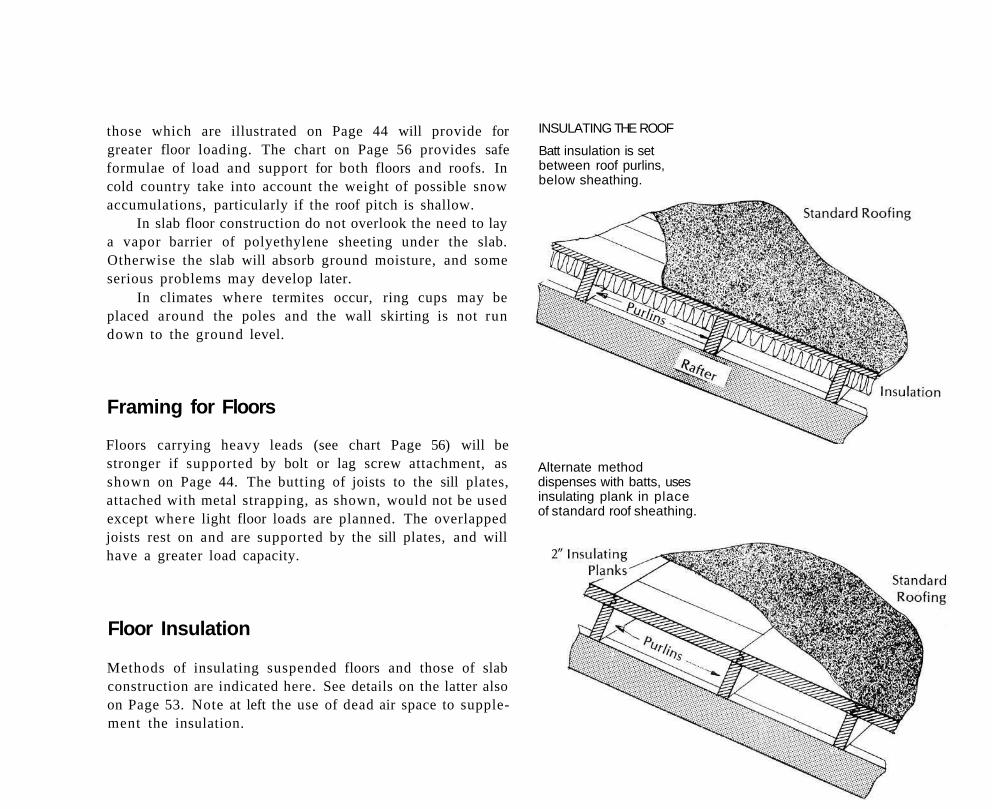
INSULATING THE ROOF
Batt insulation is set between roof purlins, below sheathing.
Alternate method dispenses with batts, uses insulating plank in place of standard roof sheathing.
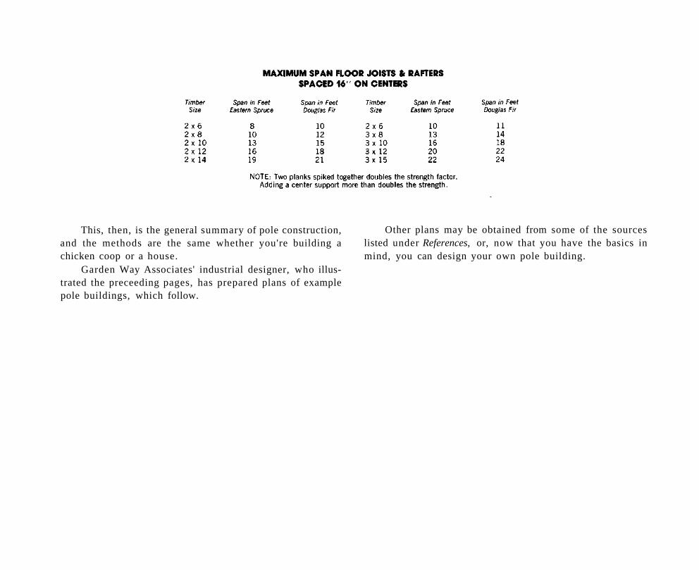
This, then, is the general summary of pole construction, and the methods are the same whether you're building a chicken coop or a house.
Garden Way Associates' industrial designer, who illustrated the preceeding pages, has prepared plans of example pole buildings, which follow.
Other plans may be obtained from some of the sources listed under References, or, now that you have the basics in mind, you can design your own pole building.
Small Barn
Here in part is what Ed Robinson of the famous "Have-More" Plan wrote in 1945 about building a small barn: "Once you decide you're going to have some livestock on your
place in the country, then it's obvious that you'll need a barn to house it.
"If you're primarily interested in the production of your family's food, you'll want a barn that is small, efficient, inexpensive and designed so simply that you can build it yourself if you so desire. Also, it would be a good idea to construct a barn that could be added to, or easily adapted to some other use.
"If you operate this barn at capacity it will produce more milk, eggs, chicken, lamb, squab, veal, turkey and rabbit
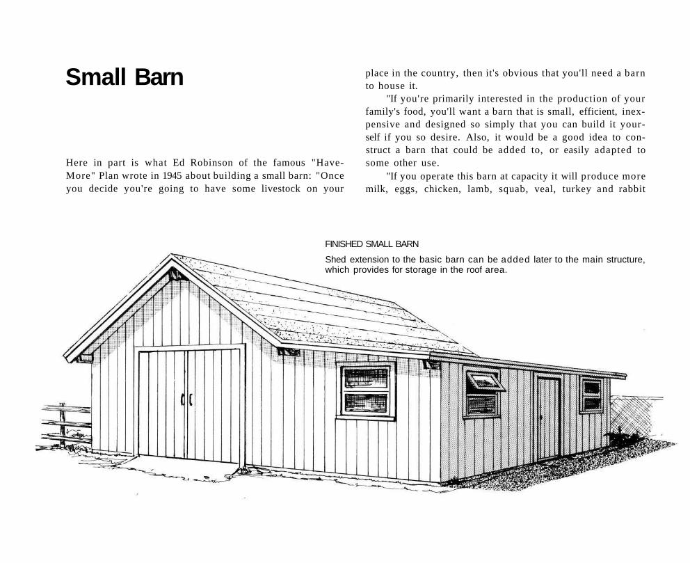
FINISHED SMALL BARN
Shed extension to the basic barn can be added later to the main structure, which provides for storage in the roof area.
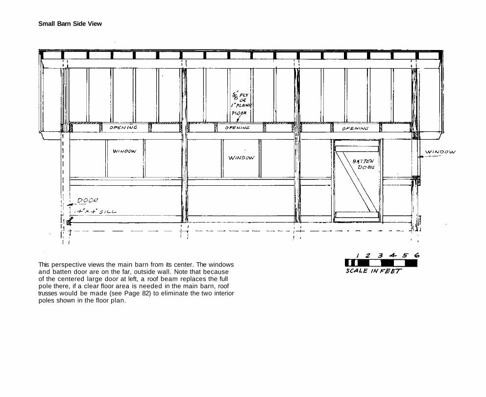
Small Barn Side View
This perspective views the main barn from its center. The windows and batten door are on the far, outside wall. Note that because of the centered large door at left, a roof beam replaces the full pole there, if a clear floor area is needed in the main barn, roof trusses would be made (see Page 82) to eliminate the two interior poles shown in the floor plan.
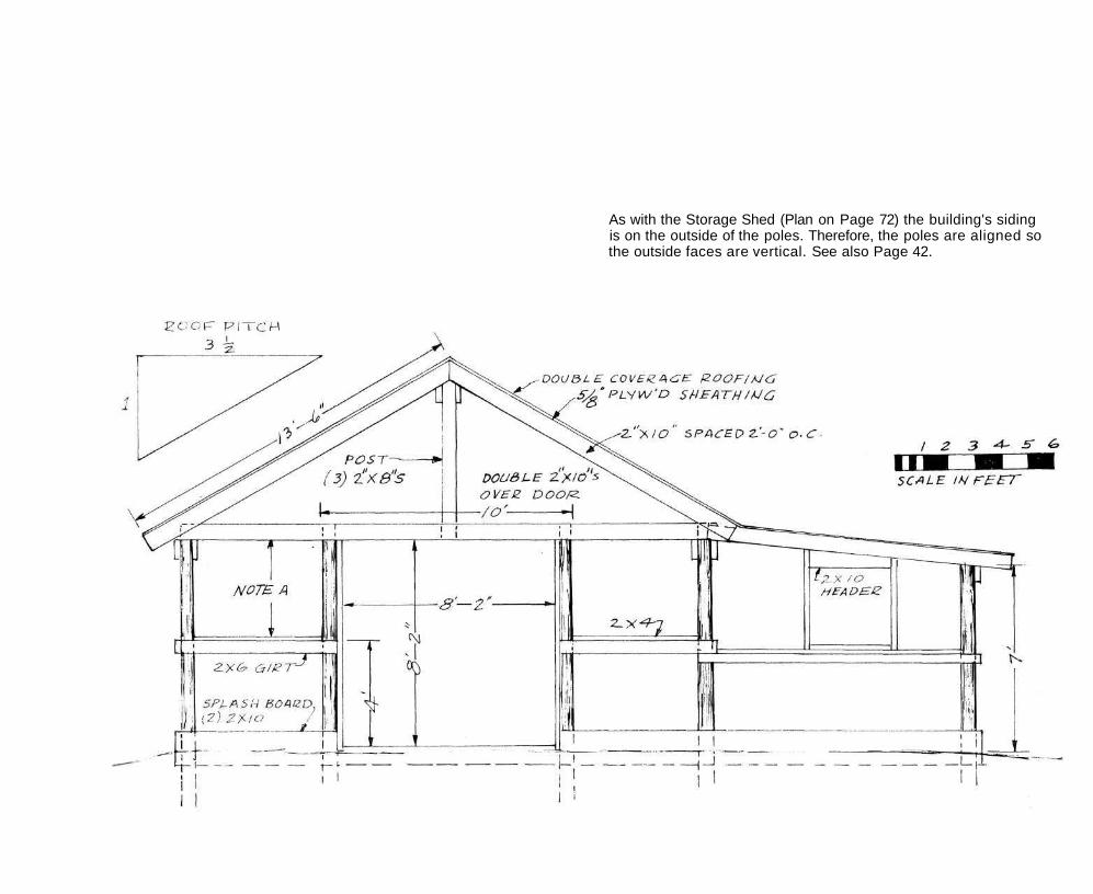
As with the Storage Shed (Plan on Page 72) the building's siding is on the outside of the poles. Therefore, the poles are aligned so the outside faces are vertical. See also Page 42.
than a family can use. By slightly enlarging or rearranging the barn, other livestock or poultry can be added or substituted.
"Many country places already have a structure that can be made into an efficient barn. If you're in doubt as to whether or not it's better to remodel or rebuild, ask a local carpenter for an estimate both ways. If you're going to do the work yourself, pay him for his advice.
"Now, if you are figuring that you might build yourself, let me add a word of encouragement. When we moved to the country and I undertook to build my barn, I actually didn't know the first thing about how to proceed. I had had a course in manual training in grammar school and learned to saw a board and hammer a nail.
"However, I learned that there is nothing complicated about building a small barn or chicken house. If a person has just a little manual dexterity, for instance the ability to drive a car, then he should be able to build a barn with plans. Carpenters, masons, plumbers and electricians love to make a great mystery of their professions—and the building codes, the building supply people, the labor unions, the utility and applicance manufacturers do their best to keep the average householder from doing any building on his own. But the truth of the matter is that most of the skills of the average mechanic are pretty simple to master. Naturally their speed and accuracy is based on years of practice. But if you've got time, you can proceed slowly, and in the end, when your barn is done, who's to know whether it was built in a week or two months?"
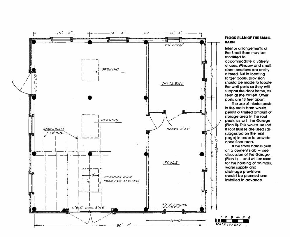
The 900 square-foot 30 x 30 barn shown here will provide for the needs of all but the most ambitious home
steader. Unlike the Robinson's barn it is a pole construction. Though a section of the interior is labeled, individual demands and desires will vary, so no attempt has been made to plan it completely. The main section could be built first and the lean-to added later.
All the information needed to erect this building is contained in the earlier text. It is important to locate the site so that drainage is away from the foundation in every direction. The floor should have 8 inches of gravel under the tamped earth floor. An improvement would be a 6-inch concrete floor poured over the gravel
The large door end of the building requires a somewhat different framing to bridge over the door. And since there is no pole in the center, a beam made of three lengths of 2 x 8s spiked together is added to support the ridge.
The doors are of the typical barn type made from vertical tongue and groove boards fastened together with battens, with at least one diagonal batten to prevent sagging. The windows are stock sizes available at lumber dealers. Establish the windows' rough opening sizes before nailing on girts, using the windows' vertical dimensions to locate the girts below the plate. Further explanation of this step will be found in the Garage Plans, Page 63.
Metal roofing can be substituted for the double coverage asphalt shown in these plans. If so, plywood roof sheathing can be omitted, although this is not recommended in cold climates, because of the insulation value and added strength provided by the plywood.
The siding used on the small Barn can be board and batten or any of the various textured plywood sidings available for exterior use.
Double Garage and Tool Shed
A choice of layouts and of roof line is possible in the construction of this building simply by moving the tool shed from the rear to either side, and by switching the location of the poles to match. In this case the distance between the poles from front to back would be 11 feet and from side to side 121/2 feet.
This choice will be determined by how best the building fits on your lot, its relation to driveway and house. Note also that in the alternate version rain will drain to the sides of the building. Where the roof slopes toward the doors, a rain gutter would be indicated*. In this plan the building is 28 V2 feet long and 25 feet wide.
Farm and country residents may wish to modify the dimensions of this building to accommodate trucks, tractors and other vehicles which require more vertical and lateral clearance than the specified 9 x 7-foot door openings, which are standard garage door dimensions. Larger overhead garage doors are available from building suppliers, though usually only on special order.
Simple modifications of these plans can be worked out to "stretch" the building both vertically and horizontally in proportions which will not materially alter the one-to-four pitch of the roof. A close calculation should be made in plan
ning any such modifications, however, to determine the increased length needed for poles, planks, boards and sheathing to keep the needs consistent with standard lumber lengths. Bear in mind also that a lesser roof pitch might cause serious problems in snow country, while a steeper pitch might destroy the visual harmony of the building's proportions.
Prior to the start of construction of the building, additional plans should be made if there will be a need for heat in the tool shed part or the whole structure.
Except in very severe climate conditions a limited heat supply in the toolshed area may be sufficient for most needs, if that room is to contain also a workbench area. Simple insulation of the toolshed walls and roof then is indicated, as well as provision for a small space heater with roof chimney located at the blind end of the shed.
In most cases electricity for lights and power tools will be important. If the building is located near the home the wiring can be brought in by underground conduit and connected (on a new circuit) to the home's central circuit box. Make a determination ahead if there is a possibility that 220-volt service will be needed in the garage for electric heating or other heavy appliances. Otherwise the service wiring should be chosen to carry the maximum anticipated use load in the building.
It is unlikely that a water supply will be required in the garage, particularly if the building is adjacent to the home and a house sillcock is located within 50 feet. Drainage of the garage floor area may prove extremely important, however, and provisions should be made if a concrete floor is poured.
Though requiring considerable care in grading, a slab that slopes gently to a drain in its center will be the best plan because it keeps water dripping from the garaged vehicles
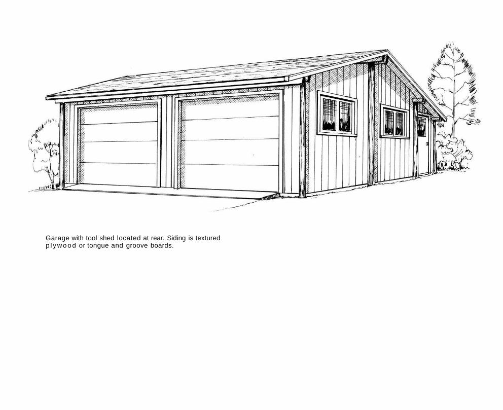
Garage with tool shed located at rear. Siding is textured p l y w o o d or tongue and groove boards.
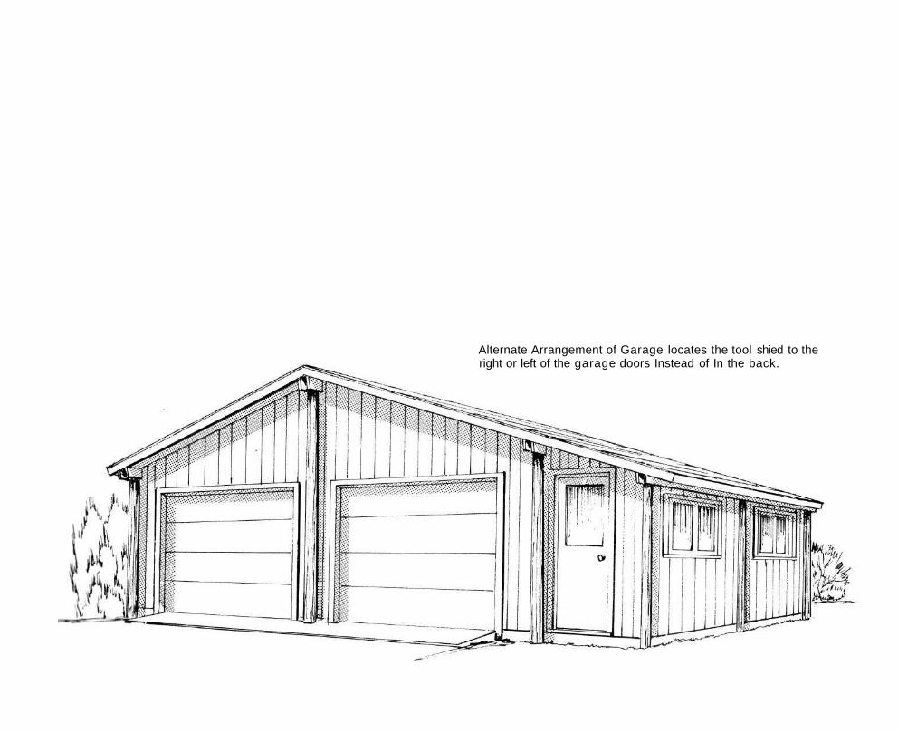
Alternate Arrangement of Garage locates the tool shied to the right or left of the garage doors Instead of In the back.
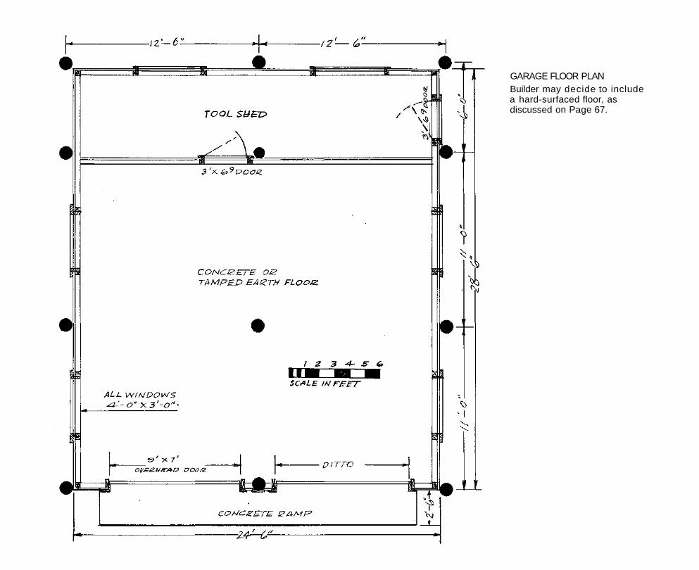
GARAGE FLOOR PLAN Builder may decide to include a hard-surfaced floor, as discussed on Page 67.
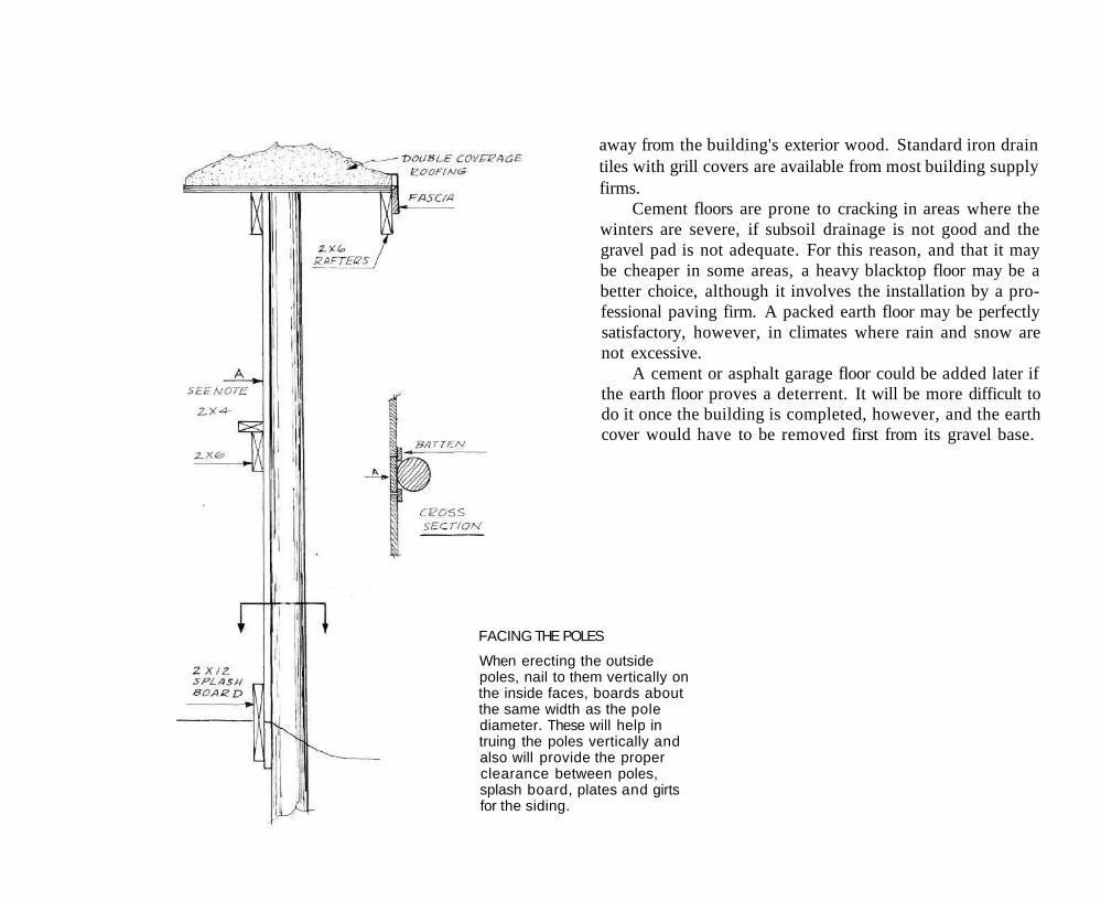
FACING THE POLES
When erecting the outside poles, nail to them vertically on the inside faces, boards about the same width as the pole diameter. These will help in truing the poles vertically and also will provide the proper clearance between poles, splash board, plates and girts for the siding.
away from the building's exterior wood. Standard iron drain tiles with grill covers are available from most building supply firms.
Cement floors are prone to cracking in areas where the winters are severe, if subsoil drainage is not good and the gravel pad is not adequate. For this reason, and that it may be cheaper in some areas, a heavy blacktop floor may be a better choice, although it involves the installation by a professional paving firm. A packed earth floor may be perfectly satisfactory, however, in climates where rain and snow are not excessive.
A cement or asphalt garage floor could be added later if the earth floor proves a deterrent. It will be more difficult to do it once the building is completed, however, and the earth cover would have to be removed first from its gravel base.
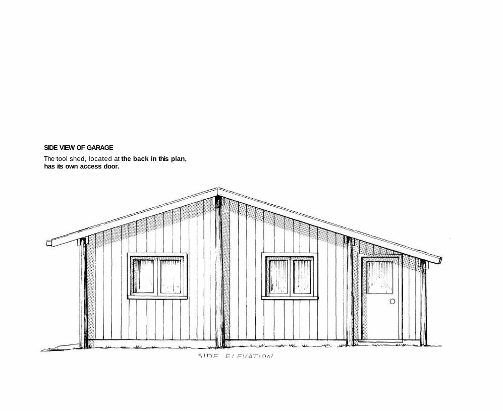
SIDE VIEW OF GARAGE
The tool shed, located at the back in this plan, has its own access door.
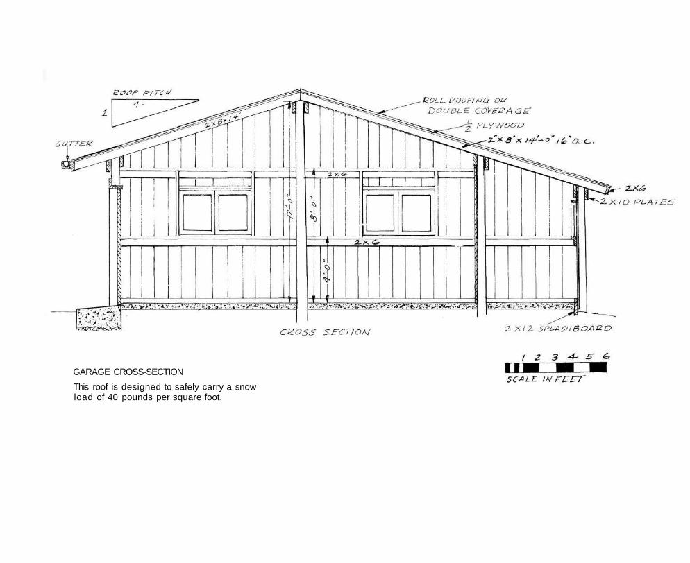
GARAGE CROSS-SECTION
This roof is designed to safely carry a snow load of 40 pounds per square foot.
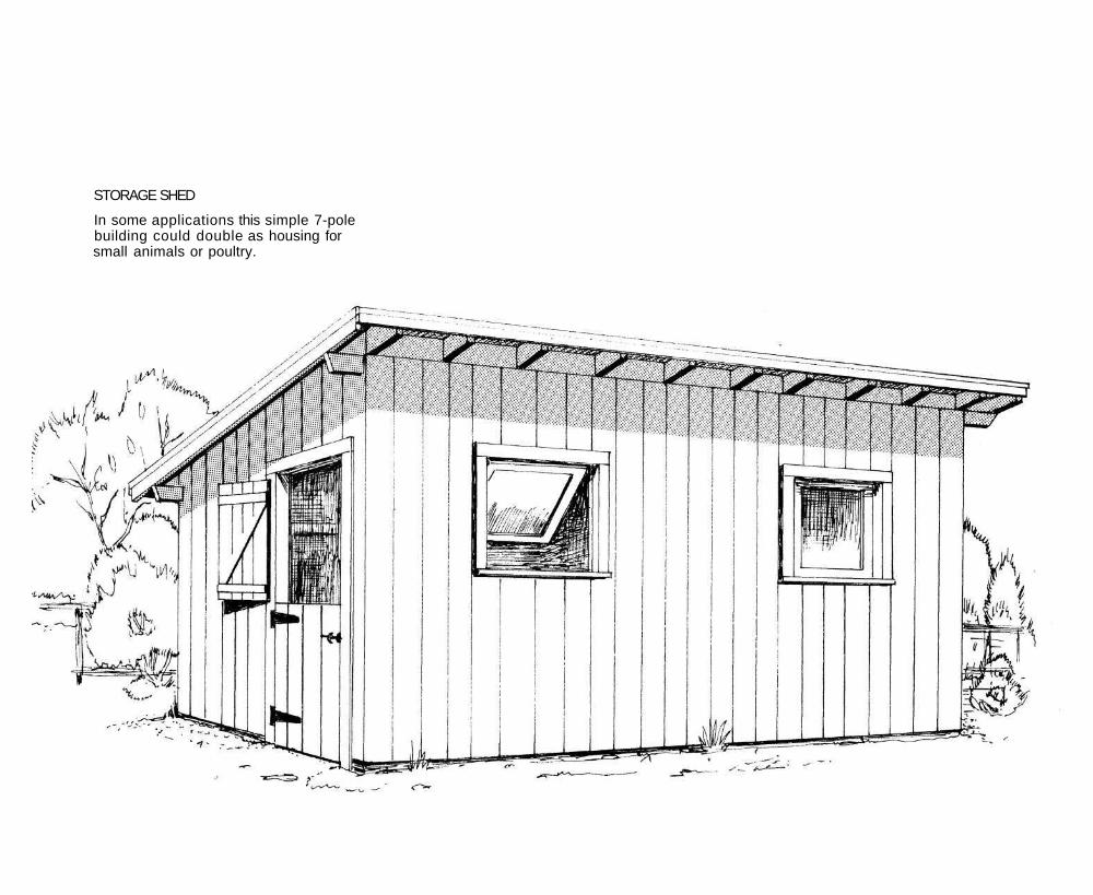
STORAGE SHED
In some applications this simple 7-pole building could double as housing for small animals or poultry.
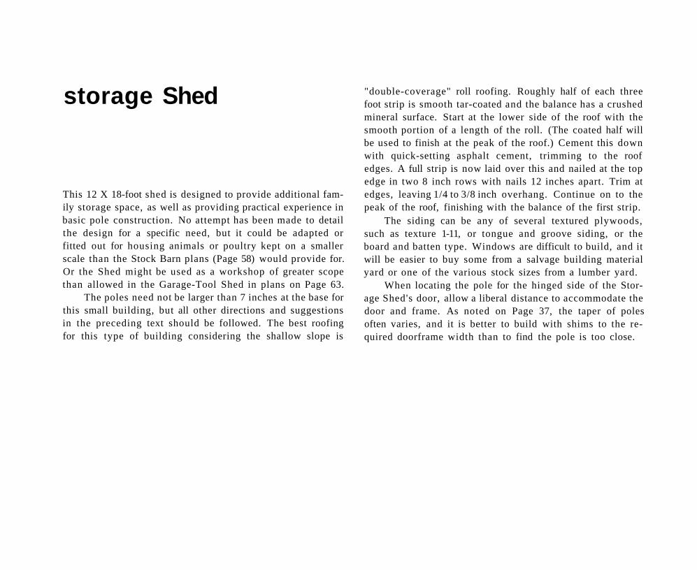
storage Shed
This 12 X 18-foot shed is designed to provide additional family storage space, as well as providing practical experience in basic pole construction. No attempt has been made to detail the design for a specific need, but it could be adapted or fitted out for housing animals or poultry kept on a smaller scale than the Stock Barn plans (Page 58) would provide for. Or the Shed might be used as a workshop of greater scope than allowed in the Garage-Tool Shed in plans on Page 63.
The poles need not be larger than 7 inches at the base for this small building, but all other directions and suggestions in the preceding text should be followed. The best roofing for this type of building considering the shallow slope is
"double-coverage" roll roofing. Roughly half of each three foot strip is smooth tar-coated and the balance has a crushed mineral surface. Start at the lower side of the roof with the smooth portion of a length of the roll. (The coated half will be used to finish at the peak of the roof.) Cement this down with quick-setting asphalt cement, trimming to the roof edges. A full strip is now laid over this and nailed at the top edge in two 8 inch rows with nails 12 inches apart. Trim at edges, leaving 1/4 to 3/8 inch overhang. Continue on to the peak of the roof, finishing with the balance of the first strip.
The siding can be any of several textured plywoods, such as texture 1-11, or tongue and groove siding, or the board and batten type. Windows are difficult to build, and it will be easier to buy some from a salvage building material yard or one of the various stock sizes from a lumber yard.
When locating the pole for the hinged side of the Storage Shed's door, allow a liberal distance to accommodate the door and frame. As noted on Page 37, the taper of poles often varies, and it is better to build with shims to the required doorframe width than to find the pole is too close.
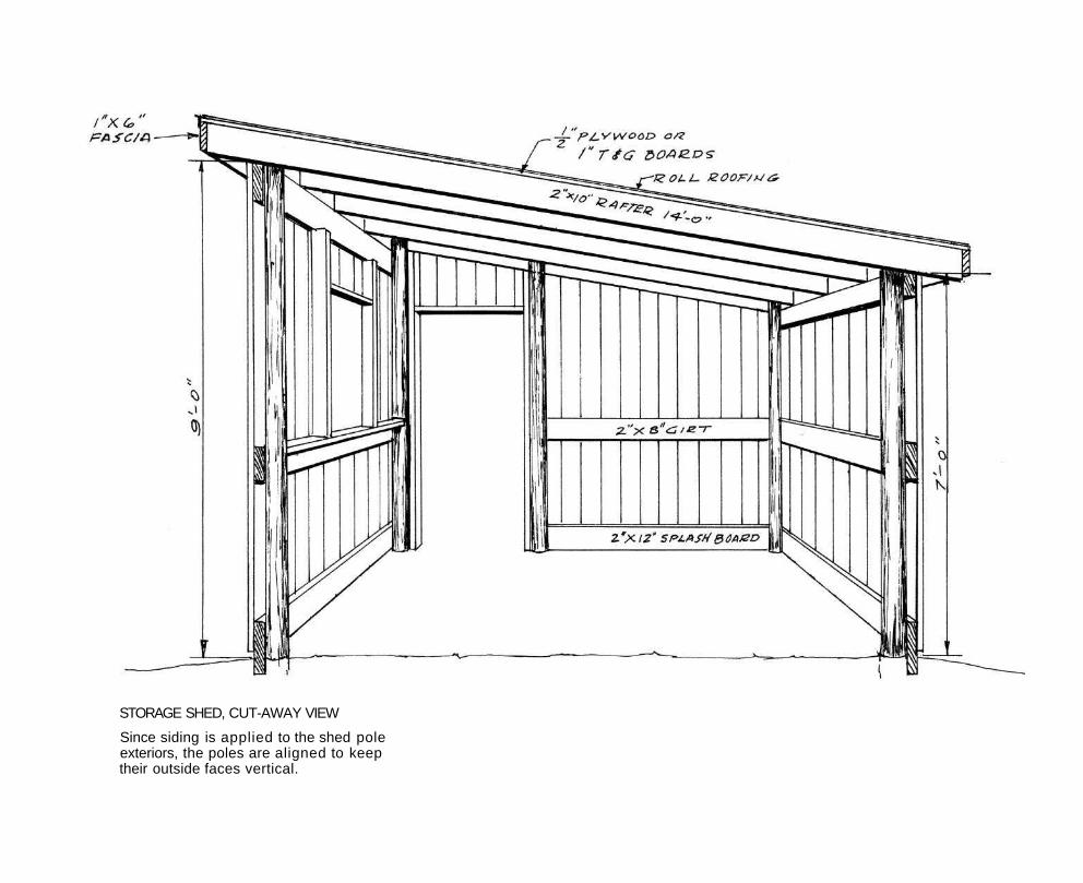
STORAGE SHED, CUT-AWAY VIEW
Since siding is applied to the shed pole exteriors, the poles are aligned to keep their outside faces vertical.
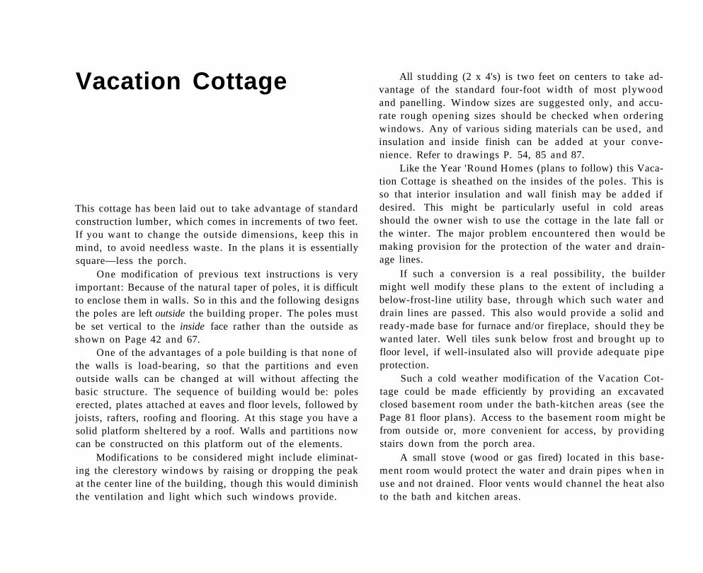
Vacation Cottage
This cottage has been laid out to take advantage of standard construction lumber, which comes in increments of two feet. If you want to change the outside dimensions, keep this in mind, to avoid needless waste. In the plans it is essentially square—less the porch.
One modification of previous text instructions is very important: Because of the natural taper of poles, it is difficult to enclose them in walls. So in this and the following designs the poles are left outside the building proper. The poles must be set vertical to the inside face rather than the outside as shown on Page 42 and 67.
One of the advantages of a pole building is that none of the walls is load-bearing, so that the partitions and even outside walls can be changed at will without affecting the basic structure. The sequence of building would be: poles erected, plates attached at eaves and floor levels, followed by joists, rafters, roofing and flooring. At this stage you have a solid platform sheltered by a roof. Walls and partitions now can be constructed on this platform out of the elements.
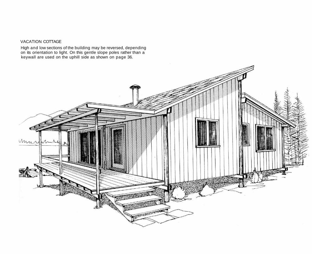
Modifications to be considered might include eliminating the clerestory windows by raising or dropping the peak at the center line of the building, though this would diminish the ventilation and light which such windows provide.
All studding (2 x 4's) is two feet on centers to take advantage of the standard four-foot width of most plywood and panelling. Window sizes are suggested only, and accurate rough opening sizes should be checked when ordering windows. Any of various siding materials can be used, and insulation and inside finish can be added at your convenience. Refer to drawings P. 54, 85 and 87.
Like the Year 'Round Homes (plans to follow) this Vacation Cottage is sheathed on the insides of the poles. This is so that interior insulation and wall finish may be added if desired. This might be particularly useful in cold areas should the owner wish to use the cottage in the late fall or the winter. The major problem encountered then would be making provision for the protection of the water and drainage lines.
If such a conversion is a real possibility, the builder might well modify these plans to the extent of including a below-frost-line utility base, through which such water and drain lines are passed. This also would provide a solid and ready-made base for furnace and/or fireplace, should they be wanted later. Well tiles sunk below frost and brought up to floor level, if well-insulated also will provide adequate pipe protection.
Such a cold weather modification of the Vacation Cottage could be made efficiently by providing an excavated closed basement room under the bath-kitchen areas (see the Page 81 floor plans). Access to the basement room might be from outside or, more convenient for access, by providing stairs down from the porch area.
A small stove (wood or gas fired) located in this basement room would protect the water and drain pipes when in use and not drained. Floor vents would channel the heat also to the bath and kitchen areas.
VACATION COTTAGE
High and low sections of the building may be reversed, depending on its orientation to light. On this gentle slope poles rather than a keywall are used on the uphill side as shown on page 36.
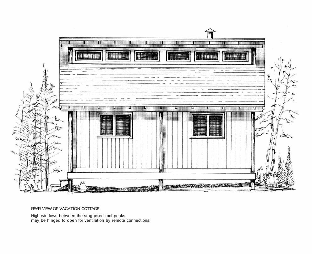
REAR VIEW OF VACATION COTTAGE
High windows between the staggered roof peaks may be hinged to open for ventilation by remote connections.
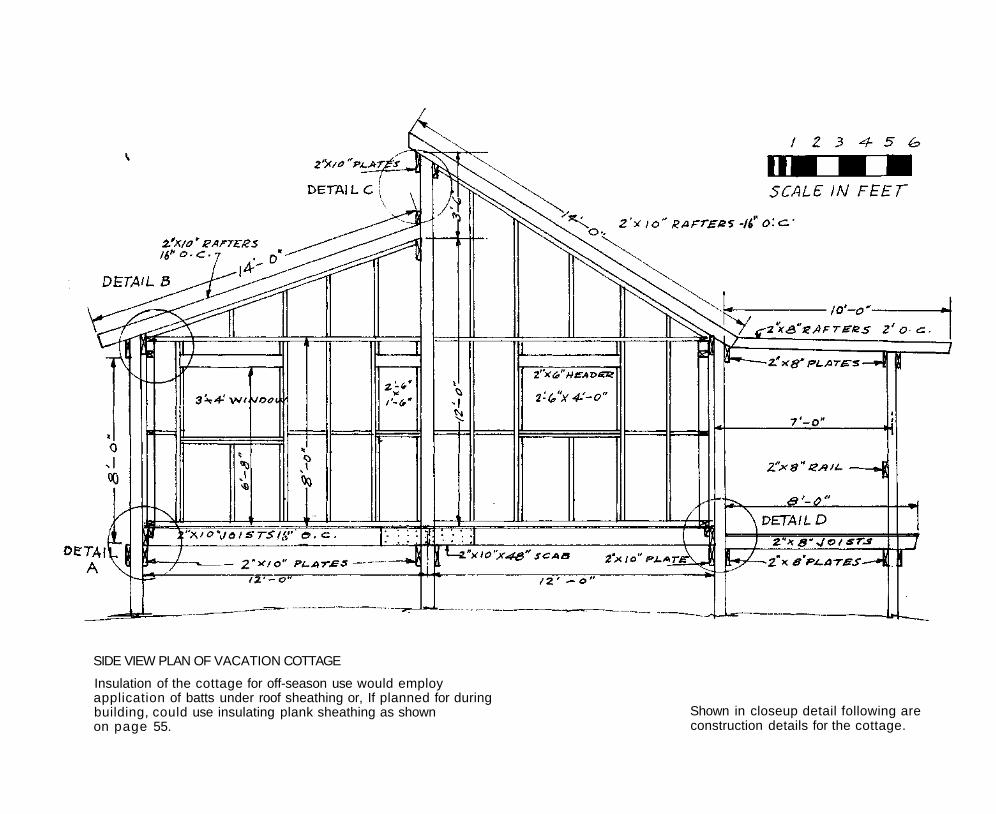
SIDE VIEW PLAN OF VACATION COTTAGE
Insulation of the cottage for off-season use would employ application of batts under roof sheathing or, If planned for during building, could use insulating plank sheathing as shown on page 55.
Shown in closeup detail following are construction details for the cottage.
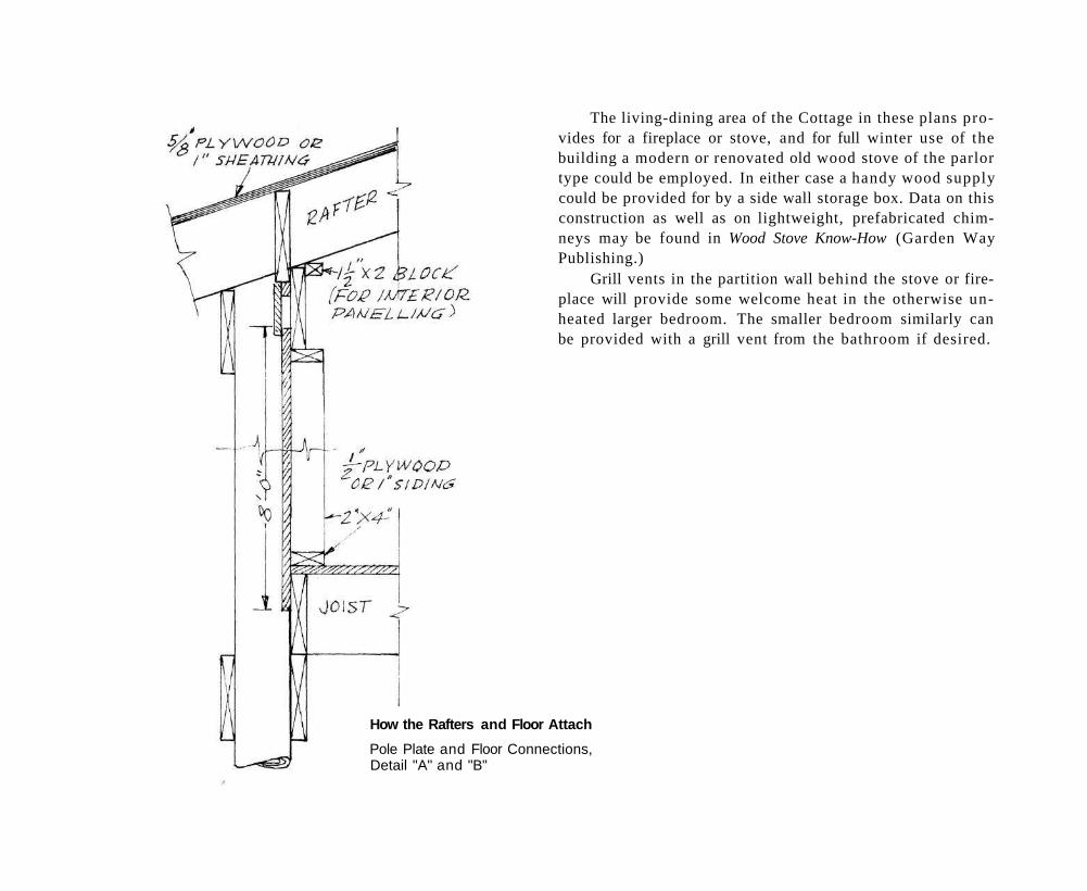
The living-dining area of the Cottage in these plans provides for a fireplace or stove, and for full winter use of the building a modern or renovated old wood stove of the parlor type could be employed. In either case a handy wood supply could be provided for by a side wall storage box. Data on this construction as well as on lightweight, prefabricated chimneys may be found in Wood Stove Know-How (Garden Way Publishing.)
Grill vents in the partition wall behind the stove or fireplace will provide some welcome heat in the otherwise unheated larger bedroom. The smaller bedroom similarly can be provided with a grill vent from the bathroom if desired.
How the Rafters and Floor Attach
Pole Plate and Floor Connections, Detail "A" and "B"
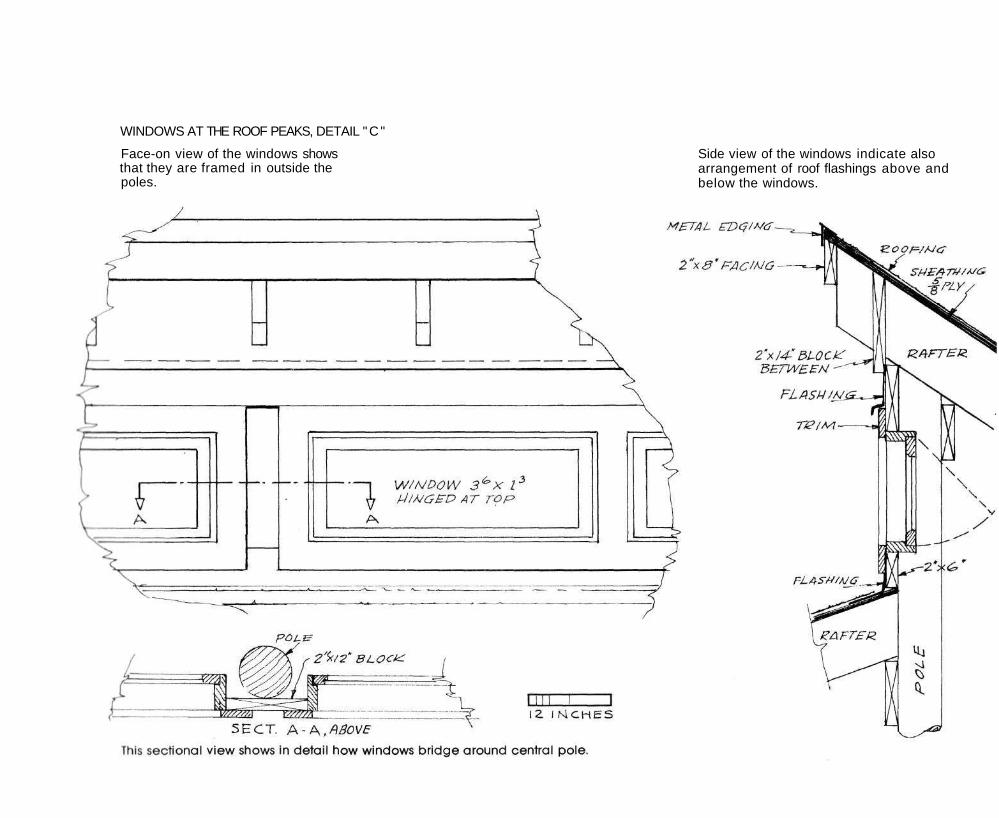
WINDOWS AT THE ROOF PEAKS, DETAIL "C"
Face-on view of the windows shows that they are framed in outside the poles.
Side view of the windows indicate also arrangement of roof flashings above and below the windows.
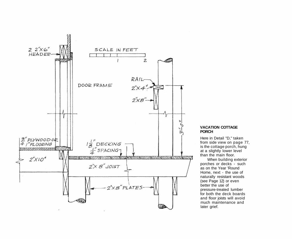
VACATION COTTAGE PORCH
Here in Detail "D," taken from side view on page 77, is the cottage porch, hung at a slightly lower level than the main floor.
When building exterior porches or decks - such as on the Year 'Round Home, next - the use of naturally resistant woods (see Page 12) or even better the use of pressure-treated lumber for both the deck boards and floor joists will avoid much maintenance and later grief.
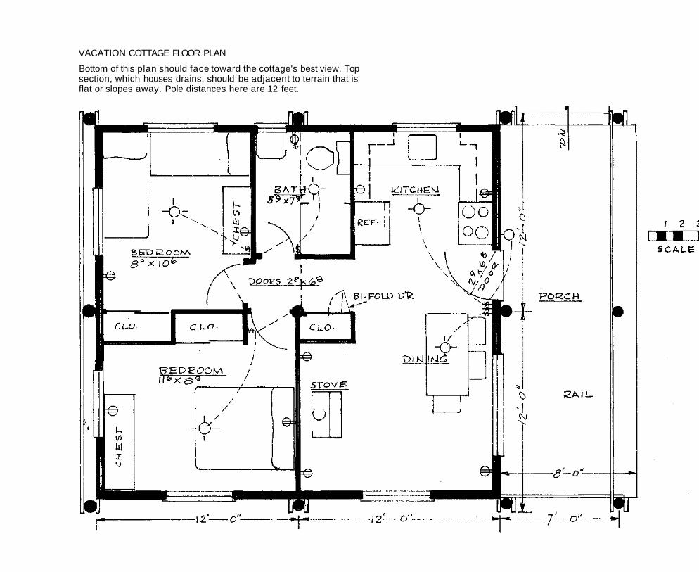
VACATION COTTAGE FLOOR PLAN
Bottom of this plan should face toward the cottage's best view. Top section, which houses drains, should be adjacent to terrain that is flat or slopes away. Pole distances here are 12 feet.
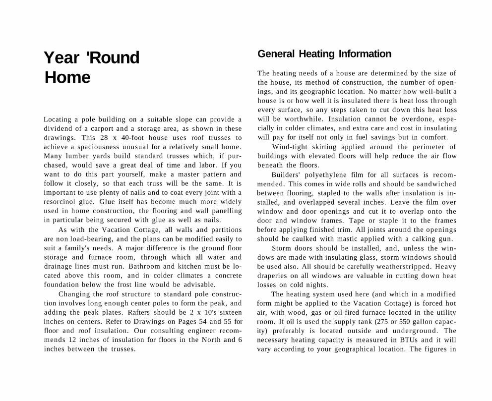
Year 'Round Home
Locating a pole building on a suitable slope can provide a dividend of a carport and a storage area, as shown in these drawings. This 28 x 40-foot house uses roof trusses to achieve a spaciousness unusual for a relatively small home. Many lumber yards build standard trusses which, if purchased, would save a great deal of time and labor. If you want to do this part yourself, make a master pattern and follow it closely, so that each truss will be the same. It is important to use plenty of nails and to coat every joint with a resorcinol glue. Glue itself has become much more widely used in home construction, the flooring and wall panelling in particular being secured with glue as well as nails.
As with the Vacation Cottage, all walls and partitions are non load-bearing, and the plans can be modified easily to suit a family's needs. A major difference is the ground floor storage and furnace room, through which all water and drainage lines must run. Bathroom and kitchen must be located above this room, and in colder climates a concrete foundation below the frost line would be advisable.
Changing the roof structure to standard pole construction involves long enough center poles to form the peak, and adding the peak plates. Rafters should be 2 x 10's sixteen inches on centers. Refer to Drawings on Pages 54 and 55 for floor and roof insulation. Our consulting engineer recommends 12 inches of insulation for floors in the North and 6 inches between the trusses.
General Heating Information
The heating needs of a house are determined by the size of the house, its method of construction, the number of openings, and its geographic location. No matter how well-built a house is or how well it is insulated there is heat loss through every surface, so any steps taken to cut down this heat loss will be worthwhile. Insulation cannot be overdone, especially in colder climates, and extra care and cost in insulating will pay for itself not only in fuel savings but in comfort.
Wind-tight skirting applied around the perimeter of buildings with elevated floors will help reduce the air flow beneath the floors.
Builders' polyethylene film for all surfaces is recommended. This comes in wide rolls and should be sandwiched between flooring, stapled to the walls after insulation is installed, and overlapped several inches. Leave the film over window and door openings and cut it to overlap onto the door and window frames. Tape or staple it to the frames before applying finished trim. All joints around the openings should be caulked with mastic applied with a calking gun.
Storm doors should be installed, and, unless the windows are made with insulating glass, storm windows should be used also. All should be carefully weatherstripped. Heavy draperies on all windows are valuable in cutting down heat losses on cold nights.
The heating system used here (and which in a modified form might be applied to the Vacation Cottage) is forced hot air, with wood, gas or oil-fired furnace located in the utility room. If oil is used the supply tank (275 or 550 gallon capacity) preferably is located outside and underground. The necessary heating capacity is measured in BTUs and it will vary according to your geographical location. The figures in
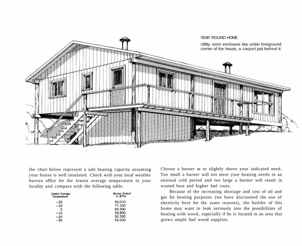
the chart below represent a safe heating capacity assuming your house is well insulated. Check with your local weather bureau office for the lowest average temperature in your locality and compare with the following table.
Choose a burner at or slightly above your indicated need. Too small a burner will not meet your heating needs in an unusual cold period and too large a burner will result in wasted heat and higher fuel costs.
Because of the increasing shortage and cost of oil and gas for heating purposes (we have discounted the use of electricity here for the same reasons), the builder of this home may want to look seriously into the possibilities of heating with wood, especially if he is located in an area that grows ample fuel wood supplies.
YEAR 'ROUND HOME
Utility room enclosure lies under foreground corner of the house, a carport just behind it.
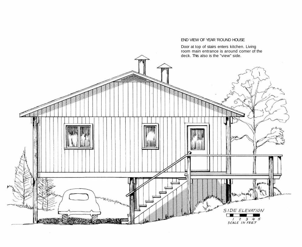
END VIEW OF YEAR 'ROUND HOUSE
Door at top of stairs enters kitchen. Living room main entrance is around comer of the deck. This also is the "view" side.
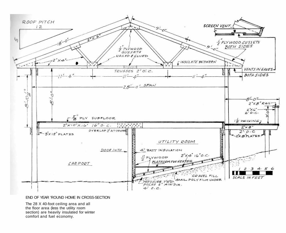
END OF YEAR 'ROUND HOME IN CROSS-SECTION
The 28 X 40-foot ceiling area and all the floor area (less the utility room section) are heavily insulated for winter comfort and fuel economy.
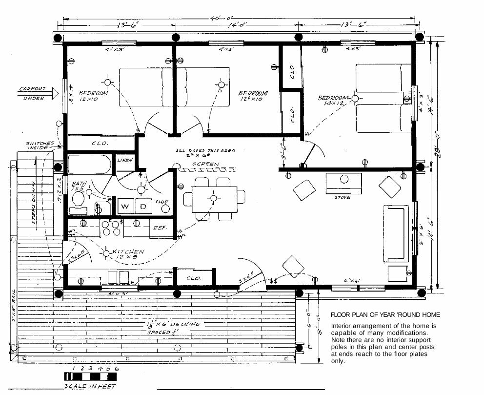
FLOOR PLAN OF YEAR 'ROUND HOME
Interior arrangement of the home is capable of many modifications. Note there are no interior support poles in this plan and center posts at ends reach to the floor plates only.
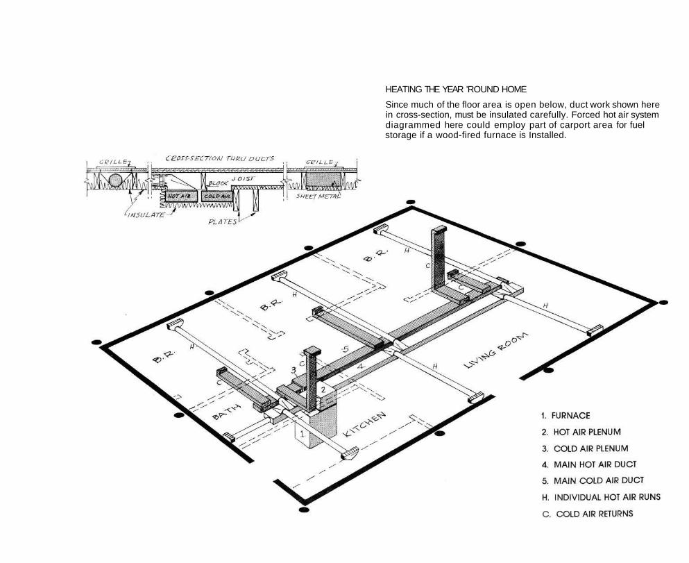
HEATING THE YEAR 'ROUND HOME
Since much of the floor area is open below, duct work shown here in cross-section, must be insulated carefully. Forced hot air system diagrammed here could employ part of carport area for fuel storage if a wood-fired furnace is Installed.
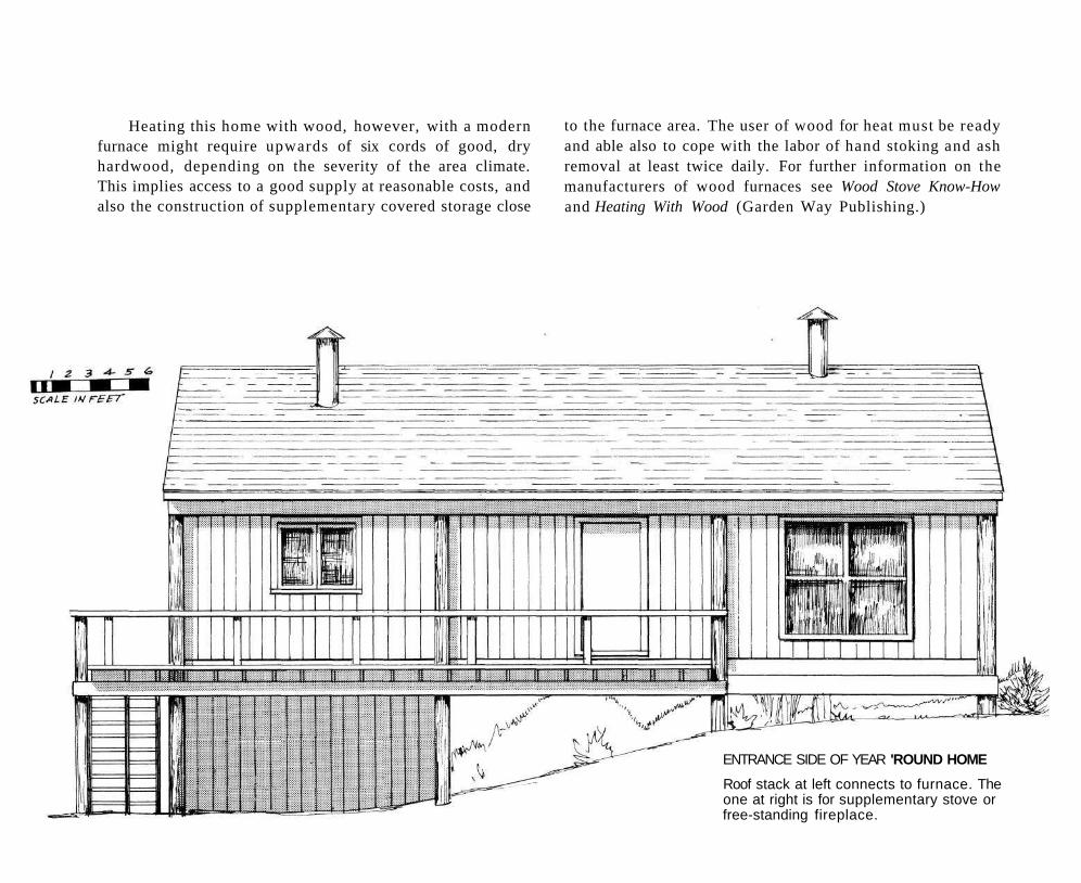
Heating this home with wood, however, with a modern furnace might require upwards of six cords of good, dry hardwood, depending on the severity of the area climate. This implies access to a good supply at reasonable costs, and also the construction of supplementary covered storage close
to the furnace area. The user of wood for heat must be ready and able also to cope with the labor of hand stoking and ash removal at least twice daily. For further information on the manufacturers of wood furnaces see Wood Stove Know-How and Heating With Wood (Garden Way Publishing.)
ENTRANCE SIDE OF YEAR 'ROUND HOME
Roof stack at left connects to furnace. The one at right is for supplementary stove or free-standing fireplace.
Of possible application here also is the combination wood and oil-fired furnace marketed by Duo-matic of Canada (Waterford, Ontario). Worth investigating in some regions, also, are coal furnaces and combination coal-oil and coal-wood heating plants manufactured by Riteway and other firms.
Finally, though the technology and equipment at this writing is not largely developed, heating of the home by the use of solar panels linked to circulated liquid radiation may be practical in sections of the country which enjoy a high ratio of sunlight hours in the winter period. Home generation of methane gas in quantities sufficient for home heating appears a very unlikely possibility except where a large cattle herd is available.
Required above the wood, gas or oil furnace are two plenums or chambers, one for the hot air feed and the other for the cold air return. From these plenums come the main rectangular ducts (8 x 16 inches.) At the appropriate places these ducts feed hot air into 6-inch diameter pipes, located between the joists, which supply hot air to each room. These ducts terminate in 90 degree boots topped with supply registers located as close as possible to the outside walls. Each of these feeder ducts should be equipped with a damper to regulate air flow.
The cold air return ducts are located in or near the interior walls and are formed by enclosing the bottom of a pair of joists with sheet metal pans, as shown in the drawing. Six-inch pipe can be used instead, if preferred, here also. The passages above the cold air ducts are blocked off with lengths of 2 X 10s. Note that the living room cold air duct is carried to the ceiling height between a pair of studs, while the kitchen and bath share a common cold air return. Both the hot and cold air ducts should be insulated as heavily as possible to minimize heat loss.
Electricity
How much of your own electrical work you can do is usually governed by the local building code. Some areas require that all electrical work be done by a licenced electrician while others have no code and use the standards set by the National Electric Code. Similarly some codes specify armored cable (metal-sheathed BX) while others permit the use of plastic covered Romex cable.
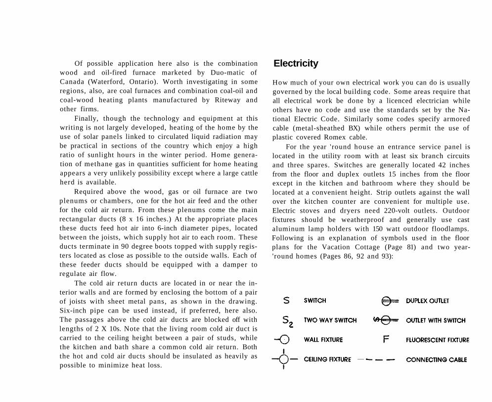
For the year 'round house an entrance service panel is located in the utility room with at least six branch circuits and three spares. Switches are generally located 42 inches from the floor and duplex outlets 15 inches from the floor except in the kitchen and bathroom where they should be located at a convenient height. Strip outlets against the wall over the kitchen counter are convenient for multiple use. Electric stoves and dryers need 220-volt outlets. Outdoor fixtures should be weatherproof and generally use cast aluminum lamp holders with 150 watt outdoor floodlamps. Following is an explanation of symbols used in the floor plans for the Vacation Cottage (Page 81) and two year-'round homes (Pages 86, 92 and 93):
Split-level Home
This 36 X 38-foot year-round house, the largest and most ambitious project in these building plans, provides for 1700 square feet of living space. It is distinguished by clerestory windows in the living room and at the top of the stairwell. The living room and both upper level rooms have balconies.
A further refinement is the centrally-located utility room's concrete foundation (with cement block or poured walls), which is shown in the Cross Section (Page 95) and also in the Lower Level Floor Plan following. These two plans also show the stairway entrance to the utility room. Additional access is provided by a sliding door off the main deck (see top left area of the Floor Plan).
Plumbing and heating appliances and connections for the house are contained in the utility room and the chimney flue runs through a corner of the kitchen. A heating duct diagram is not included here, but could be planned in similar fashion to that shown with the preceeding Year 'Round Home Plan on Page 87. The use of baseboard hot water heating is recommended, however, for ease of installation.
Procedures for construction follow the main text generally. The outside poles should be trued up on their inside faces, following the instructions given in the caption on Page
In these plans all the floor joists are connected to the plates by manufactured metal joist hangers (see Page 20), except where the upper decks or hanging balconies occur. So that these balcony joists will be cantilevered, the plates at these points are lowered the width of the joists, rather than being flush—as shown in the Balcony Detail view.
Because of the flat surfaces of the roofs, built-up gravel surfaced roofing should be planned there. Heavier than usual roof rafters and upper plates are used (see Cross Section Page 95) to allow for the extra weight of this roofing and also a possible snow load increase. Pole distances are 12 feet.
In northern climates the roof areas, as well as side walls and floors, should be heavily insulated (see General Heating Information under the plans on Page 82). The furnace for this house, when built for severe winters, should have a 160,000 BTU capacity. The electric service entrance panel, located in the utility room, should be of 200 amperes size.
Since none of the walls of the house is load-bearing, the wall studs could be located 24 inches on centers rather than the usual 16 inches. This would effect some savings in materials and in labor. The floor joists, however, should be kept at 16 inches on centers.
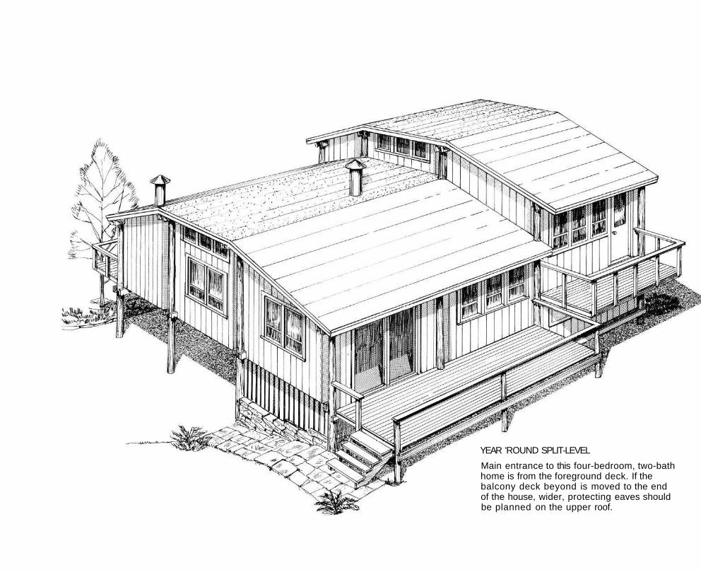
YEAR 'ROUND SPLIT-LEVEL
Main entrance to this four-bedroom, two-bath home is from the foreground deck. If the balcony deck beyond is moved to the end of the house, wider, protecting eaves should be planned on the upper roof.
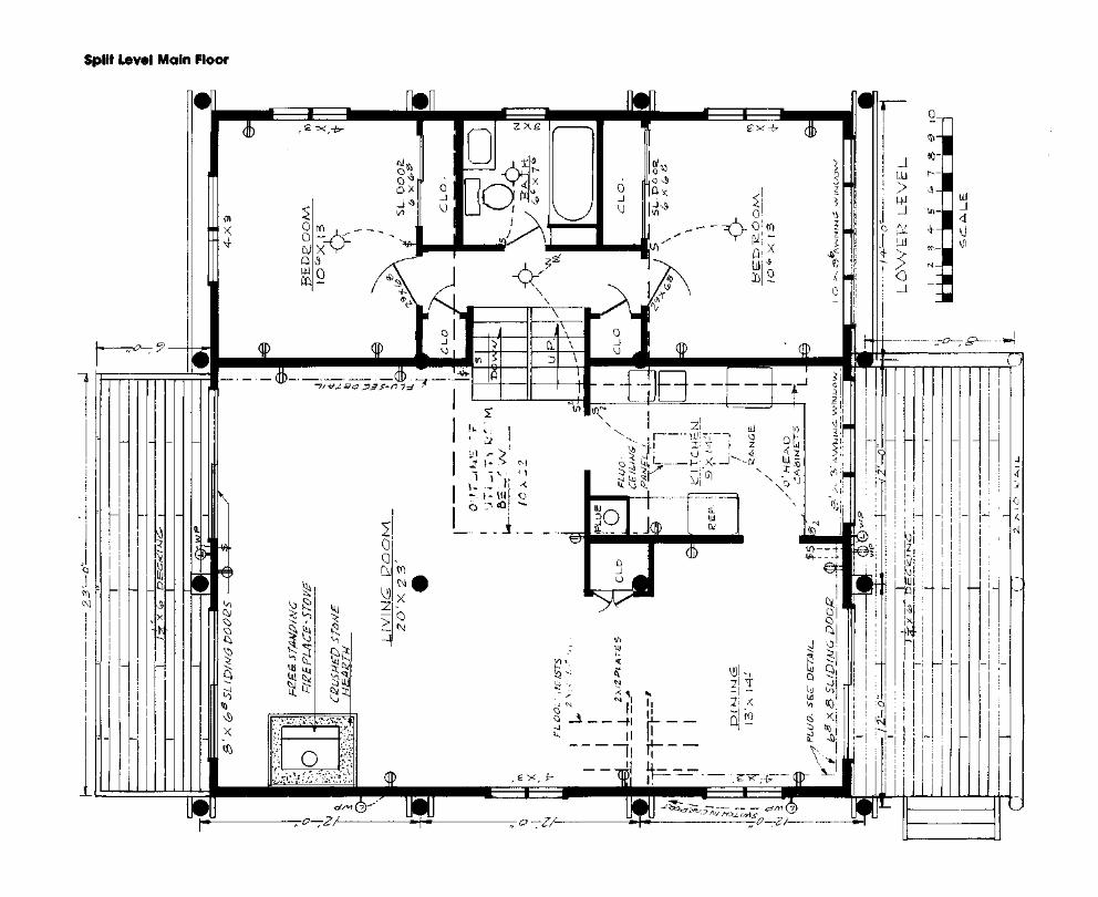
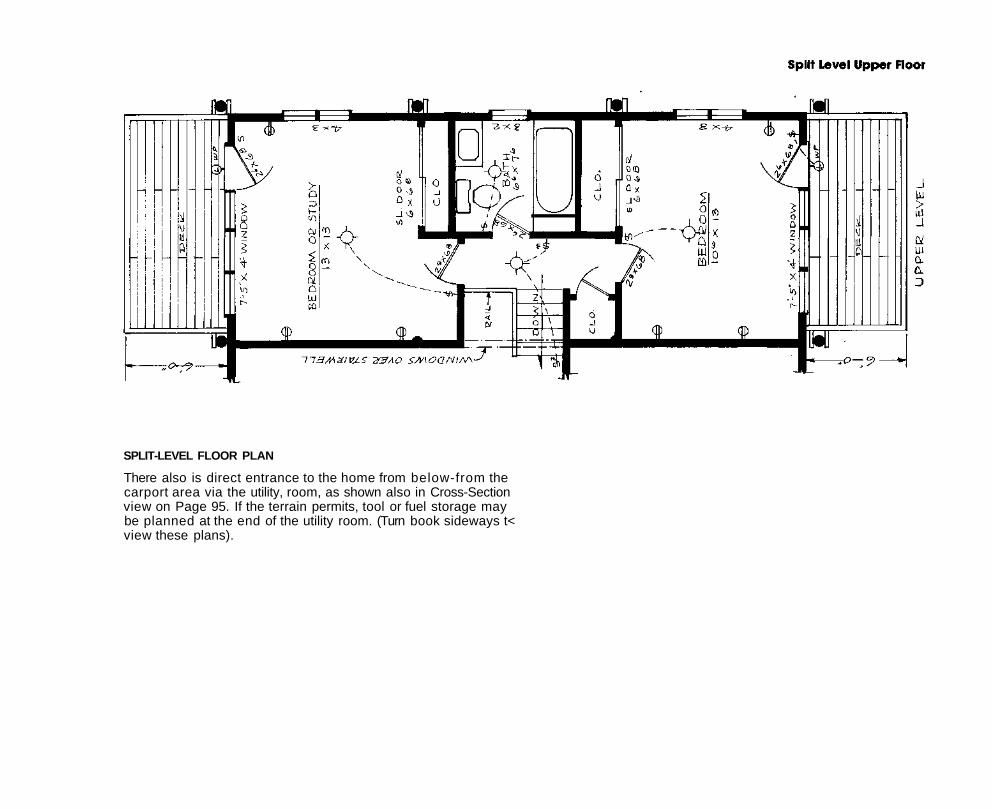
SPLIT-LEVEL FLOOR PLAN
There also is direct entrance to the home from below-from the carport area via the utility, room, as shown also in Cross-Section view on Page 95. If the terrain permits, tool or fuel storage may be planned at the end of the utility room. (Turn book sideways t< view these plans).
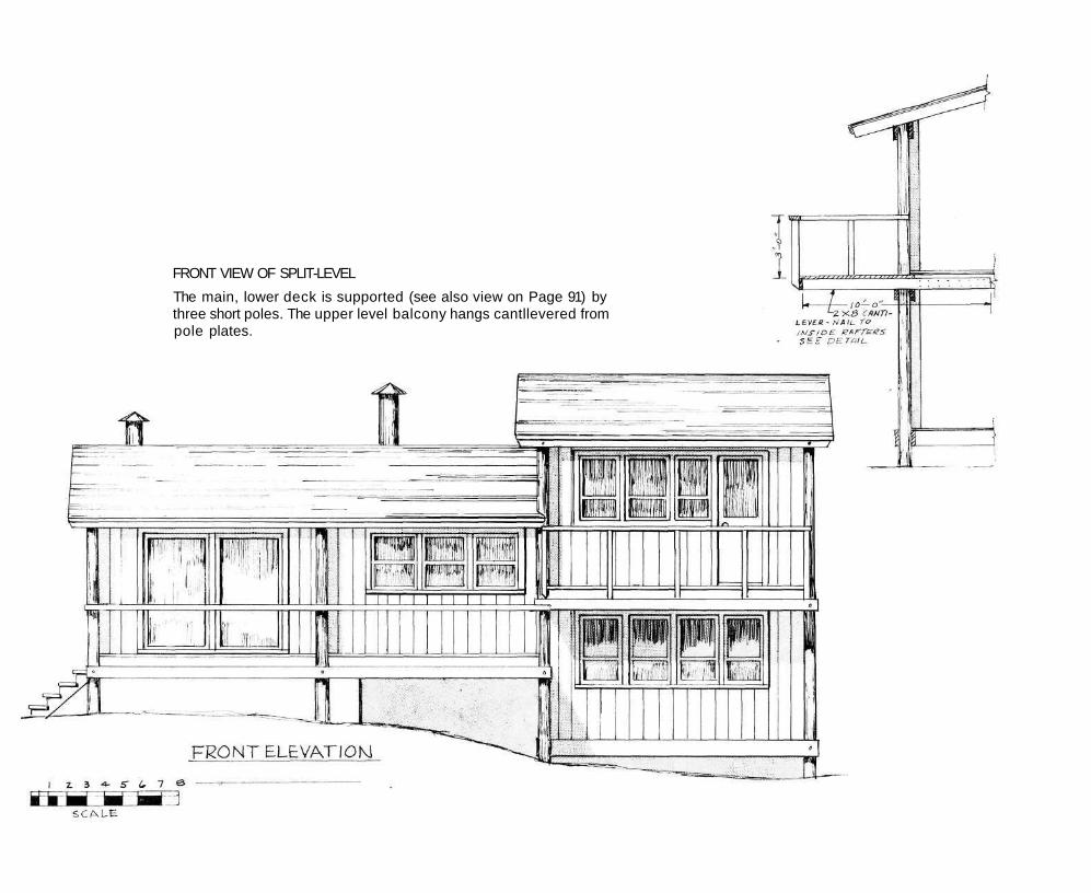
FRONT VIEW OF SPLIT-LEVEL
The main, lower deck is supported (see also view on Page 91) by three short poles. The upper level balcony hangs cantllevered from pole plates.
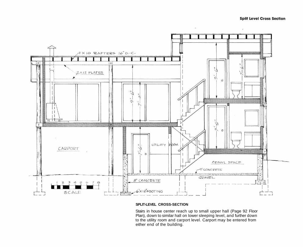
SPLIT-LEVEL CROSS-SECTION
Stairs in house center reach up to small upper hall (Page 92 Floor Plan), down to similar hall on lower sleeping level, and further down to the utility room and carport level. Carport may be entered from either end of the building.
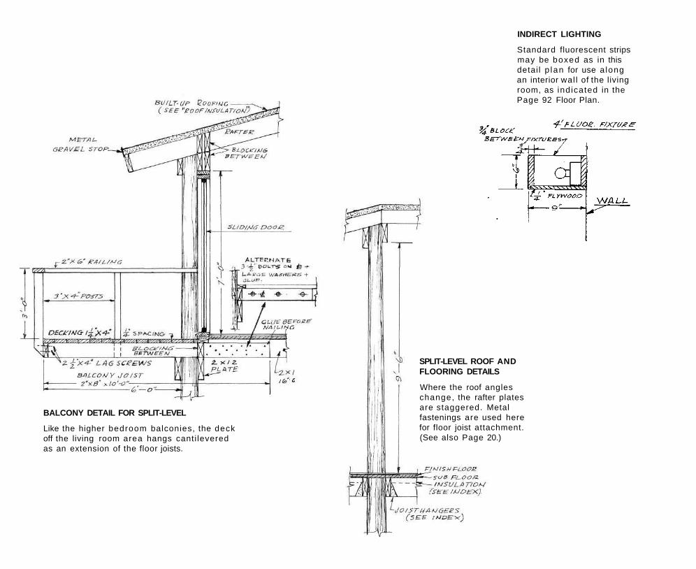
INDIRECT LIGHTING
Standard fluorescent strips may be boxed as in this detai l p lan for use a long an interior wal l of the living room, as indicated in the Page 92 Floor Plan.
SPLIT-LEVEL ROOF AND FLOORING DETAILS
Where the roof angles change, the rafter plates are staggered. Metal fastenings are used here for floor joist attachment. (See also Page 20.)
BALCONY DETAIL FOR SPLIT-LEVEL
Like the higher bedroom balconies, the deck off the living room area hangs canti levered as an extension of the floor joists.
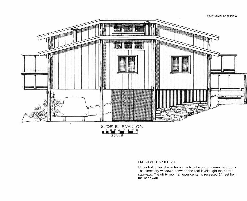
END VIEW OF SPLIT-LEVEL
Upper balconies shown here attach to the upper, corner bedrooms. The clerestory windows between the roof levels light the central stairways. The utility room at lower center is recessed 14 feet from the near wall.