low-cost laser scanning system design
TRANSCRIPT
Journal of Russian Laser Research, Volume 35, Number 3, May, 2014
LOW-COST LASER SCANNING SYSTEM DESIGN
Onur Akyol1 and Zaide Duran2
1Tubitak Marmara Research Center
Environmental Institute
Gebze 41470, Kocaeli, Turkey2Istanbul Technical University
Civil Engineering Faculty
Geomatics Engineering Department
Maslak 24469, Istanbul, Turkey∗Corresponding author e-mail: duranza@ itu.edu.tr
e-mail: onur.akyol@ tubitak.gov.tr
Abstract
3D data is the main element of three-dimensional models that are commonly used in many differentapplication areas such as architecture, archeology, medicine, film production, reverse engineering, etc.In this study, we discuss designing and utilizing opportunities for a low-cost triangulation-based laserscanner. To evaluate the system, a test object is specially designed, and the accuracy and operationof the system are verified by comparing the data output of the laser scanner with the terrestrialphotogrammetric method. The designed system is also verified using different objects. At the endof the study, we calculate the precision of the scanned sample models to be 0.1–0.2 mm and RMS,0.59 mm.
Keywords: 3D modeling, 3D laser scanning, close range photogrammetry, low-cost laser scanner.
1. Introduction
Describing some complex geometrical features of objects and create a 3D computer-aided-design
(CAD) model can be very difficult. To solve this problem, a physical handmade model can be produced
as a representation of designs [1]. For recreating the shape and surface of objects, optical scanning based
on structural light and laser scanning methods and photogrammetric techniques are widely used [2].
Photogrammetry has dealt with the 3D reconstruction of objects from images for many years. It provides
accurate sensor calibration and object modeling using analog or digital imageries, it is very portable, and
many commercial softwares are available for image processing and 3D modeling [3].
With the increasing demand for 3D models, the high costs of point-based laser scanners and difficulty
in processing the data obtained from these devices have led to the development of low-cost alternatives
of 3D scanning methods [4]. Surface data of an object are collected as 3D coordinates using terrestrial
laser scanners (TLS). The scanning process is done automatically and systematically and thousands of
the points’ three-dimensional x, y, z coordinates can be reached in seconds. A set of high-density spots
derived from TLS is usually collected as a point cloud during the scanning process. This collected point
cloud can be displayed simultaneously [5].
Laser scanners can be classified into three classes according to their working principles, namely, time
of flight, phase shift, and triangulation-based laser scanners.
244
Manuscript submitted by the authors in English first on June 4, 2013 and in final form on October 25, 2013.
1071-2836/14/3503-0244 c©2014 Springer Science+Business Media New York
Volume 35, Number 3, May, 2014 Journal of Russian Laser Research
The basic principle of triangulation-based systems consists in the fact that determination of the beam
space, which is formed by camera, laser source, and the object, is done mathematically and establishes
the relationship between the image and object coordinates (Fig. 1). Thus, new 3D point coordinates
can be calculated with the help of mathematical expressions. A background shown in Fig. 2, which
has control points on it, is employed in the DAVID laser scanning system to establish the relationship
between the image and object coordinates. The laser ray, being expanded to a plane by a cylindrical lens,
has to intersect two objects at the same time: the (unknown) surface, and the a priori known reference
geometry (usually the background). The visible intersection with the background is used to calibrate
the laser, i.e., to calculate the exact 3d pose of the laser plane ELaser.∗ On the other hand, the camera
should be calibrated.
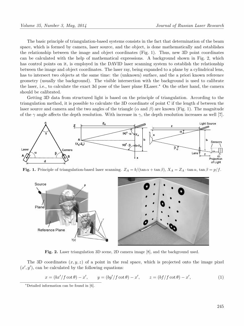
Getting 3D data from structured light is based on the principle of triangulation. According to the
triangulation method, it is possible to calculate the 3D coordinate of point C if the length d between the
laser source and camera and the two angles of the triangle (α and β) are known (Fig. 1). The magnitude
of the γ angle affects the depth resolution. With increase in γ, the depth resolution increases as well [7].
Fig. 1. Principle of triangulation-based laser scanning. ZA = b/(tanα+ tanβ), XA = ZA · tanα, tanβ = p/f .
Fig. 2. Laser triangulation 3D scene, 2D camera image [8], and the background used.
The 3D coordinates (x, y, z) of a point in the real space, which is projected onto the image pixel
(x′, y′), can be calculated by the following equations:
x = (bx′/f cot θ)− x′, y = (by′/f cot θ)− x′, z = (bf/f cot θ)− x′, (1)
∗Detailed information can be found in [6].
245
Journal of Russian Laser Research Volume 35, Number 3, May, 2014
where b is the baseline length, θ is the laser beam angle, and f is the focal length [6].
In this study, we elaborated on a design of the laser scanner operating on the basis of the triangulation
method. We compare this technique with the other methods employed for 3D modeling. For this purpose,
we use a home-made, low-cost scanning device called the DAVID laser scanner. The DAVID laser scanner
consists of a camera, a hand-held line laser, and two plain boards for background. It is a very easy tool
to implement, and results get better after a few try. It allows one to scan and digitize the 3D objects. In
this way, anyone can do low-cost three-dimensional scanning.
2. System Architecture
In this study, we used the DAVID laser scanner software. The hardware part of the scanning system
was set according to triangulation-based laser-scanning basics. For obtaining 3D data, we used a camera,
a laser line module, and a background panel. Also, we built a mechanical system for laser line movement.
With the help of this mechanism, it is possible to move the laser line around a constant axis with various
speeds. The mechanical system for the laser line continuous movement at constant rate is based on a
stepper motor with gear mechanism.
The DAVID laser scanner software works with a video camera for sensing the image. In the designed
system, we used a Logitech Webcam Pro 9000 high-definition video camera and a red laser line with a
wavelength of 650 nm as hardware. To obtain geometric data, a background plane that contains the
control points was used.
Also we developed an electronic system for controlling the mechanical section of the system. A
programmable interface controller (PIC) microcontroller controls the action of the stepper motor (Fig. 3).
Thus, the rotation direction and the speed of the stepper motor were preprogrammed to automate the
system. A general view of the designed system is shown in Fig. 4 [10].
3. Comparison of Various Methods for Accuracy Research
The cost of the designed system is approximately 1,000 USD. For determining the accuracy of the
system, a test object specially designed for this study was scanned with terrestrial photogrammetric
techniques and geodetic methods, as well as the designed system. Digital close-range photogrammetric
technique was used for obtaining precise measures and a 3D model of the test object (Fig. 5). After the
photogrammetric evaluation, the test object was also modeled using data obtained from the designed
system in order to compare the two different techniques. The industrial surveying instruments have the
capability of high precision data production for geodetic measurements. They are used in works requiring
high precisions, such as the design of industrial products and quality control purposes.
In the study, the test object was measured and modeled using a Cyclone 3D scanner probe. The
model obtained was used as a reference for a comparison between photogrammetric and laser-scanner
techniques.
Each 3D model obtained from the photo modeler, Cyclone 3D scanner probe, and designed laser
scanner are compared with one another. Since all 3D models obtained by different techniques are in
different coordinate systems, they must be transformed to a common reference frame. For this purpose,
all models are exported to Geomagic software and transformed to one selected reference model by applying
246

Volume 35, Number 3, May, 2014 Journal of Russian Laser Research
Fig. 3. Laser triangulation 3D scene and 2D camera image and the background used.
Fig. 4. General view of the laser scanning system.
Fig. 5. Photogrammetric evaluation step and 3D modelof test object using photo modeler software.
Fig. 6. Comparison (in mm) of the results obtained bythe Cyclone 3D laser scanner and the low-cost laser scan-ning model (a) and the results obtained by the Cyclone3D laser scanner and the photogrammetric model (b).
247

Journal of Russian Laser Research Volume 35, Number 3, May, 2014
manual registration. At the end of the process, all 3D models are transformed to a common coordinate
system. Thus, it becomes possible to make a 3D surface analysis between the models. This analysis,
graphically represented in Fig. 6, shows the deviations on the surfaces between the two compared models.
Fig. 7. Measurements of test objects using the laser scanner wedesigned.
As the second step of the accuracy
assessment, some measurements were
carried out on each 3D model. For this
purpose, some edges of the object were
measured on models (Fig. 7). Then
the measured values on the different 3D
models of the same object were com-
pared with one another. Comparisons
of the methods are shown in the Tab-
les 1 and 2, where the data obtained
from the 3D probe were accepted as the
reference values.
Table 1. Comparison of Edge Lines.
Edge 3D Terrestrial Laser |v1| |v2|# Measurement Photogrammetric Scanner (mm) (mm)
Probe (mm) Technique (mm) (mm)
1 46.50 46.74 45.79 0.24 0.71
2 44.93 45.30 45.50 0.37 0.57
3 64.22 64.79 64.75 0.57 0.53
4 110.20 109.66 109.91 0.54 0.29
5 111.62 111.81 112.08 0.19 0.46
6 155.95 156.01 155.51 0.06 0.44
7 61.23 60.58 60.35 0.65 0.88
8 33.60 34.02 33.55 0.42 0.05
9 153.01 153.11 153.84 0.11 0.83
10 42.46 42.68 42.14 0.22 0.32
As shown in Tables 1 and 2, four diagonal lines and ten lines on the edges are used for calculating the
root-mean-square (RMS) error of the system. In the tables, the error values are shown in columns v1 and
v2. Numerical differences between the two methods are listed in columns |v1| and |v2| [9]. Measurements
obtained from probe measurements are taken as reference: |v1| indicates the error value between the 3D
measurement probe and the terrestrial photogrammetric technique, while |v2| indicates the error betweenthe 3D measurement probe and the laser scanner. The maximum error of the terrestrial photogrammetric
technique is 0.65 mm on edge 7, where the laser scanner system has 0.98 mm on diagonal 13. With these
measurements, it is possible to calculate the RMS of the system.
248

Volume 35, Number 3, May, 2014 Journal of Russian Laser Research
Table 2. Comparison of Diagonal Lines.
Diagonal 3D Terrestrial Laser |v1| |v2|# Measurement Photogrammetric Scanner (mm) (mm)
Probe (mm) Technique (mm) (mm)
11 222.69 222.81 222.14 0.12 0.55
12 192.11 192.36 191.55 0.25 0.56
13 218.40 218.64 217.42 0.24 0.98
14 221.71 221.96 221.85 0.25 0.14
Then, using the following true error formula, we calculate the relative accuracies for the photogram-
metric method and the laser scanning method as m0 Photogrammetry = ±0.41 mm and m0 Laser scanning =
±0.59 mm, respectively,
m0 =√
[vv]/(n− 1). (2)
4. 3D Output Data Samples
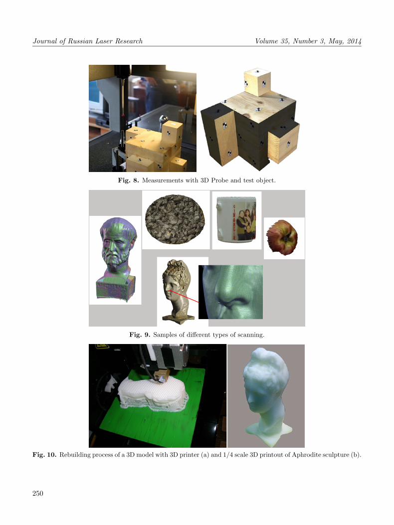
Objects with various shapes and structures, such as two different sculptures, half an apple, a handless
mug, an asphalt sample, and a test object were scanned with the laser scanner designed in this study
(Fig. 9). In this way, we examined the performance of the laser scanner for different types of objects.
Thus, we tested the use of the system and determined the problems encountered for different objects.
5. Conclusions
The laser scanning system that we built in this study is a low-cost system. A comparative study of
different methods of 3D modeling showed that it was effective in obtaining the results. The scanning
sensitivity and resolution of the model is proportional to the resolution of the camera used. The precision
of the scanned sample models is 0.1–0.2 mm. The data are produced with a spatial data accuracy of
0.59 mm. Such sensitivity and accuracy are sufficient for many applications, such as visualization,
3D modeling, documentation, and 3D printing. We also proved that the terrestrial photogrammetric
technique is as reliable as conventional geodetic methods.
Using the system designed, it is possible to get effective 3D models of especially small-scale objects.
The software provided by the DAVID laser scanner allows one to do the texture mapping with real texture
data. Thus, it is possible to create detailed virtual-reality models using the data obtained. There are
some important issues to be taken into consideration in order to achieve accurate and efficient results
while scanning with such a kind of system. The most important issue is the location of the camera and
the laser. One must provide an appropriate base between the camera and the laser source, and triangle
angles should not be small. Another important issue is the thickness of the laser line. We observed that
a thin and well-focused laser line provided better results. On the other hand, if the light quantity coming
to the camera sensor is adjusted from the video settings of the software, the final data includes less noise.
The limitation of the system is the size of the objects. It is possible to scan objects only if their sizes are
less than the plain board designed for the system.
249
Journal of Russian Laser Research Volume 35, Number 3, May, 2014
Fig. 8. Measurements with 3D Probe and test object.
Fig. 9. Samples of different types of scanning.
Fig. 10. Rebuilding process of a 3D model with 3D printer (a) and 1/4 scale 3D printout of Aphrodite sculpture (b).
250

Volume 35, Number 3, May, 2014 Journal of Russian Laser Research
Acknowledgments
The equipment and electronic cards constructed by Emrah A. Pekdemir are highly appreciated.
References
1. M. Wylezo�l, Modelowanie Inzynierskie, 32, 485 (2006).
2. K. Oczos and I. Cena, Mechanik, 3, 165 (2008).
3. Z. Duran and U. Aydar, “Digital modeling of world’s first known length reference unit: the Nippur
cubit rod,” J. Cultural Heritage, 13, 352 (2012).
4. http://www.david-laserscanner.com/
5. K. Gumus and H. Erkaya, “Using the terrestrial laser scanner systems for engineering applications,”
The 11th Turkey Map Scientific and Technical General Assembly, UCTEA Chamber of Survey and
Cadastre Engineers, Ankara, Turkey (2007).
6. A. Peiravi and B. Taabbodi, Am. J. Sci., 6, 80 (2010).
7. L. Zagorchev and A. Goshtasby, Comput. Vis. Image Understand., 101, 65 (2006).
8. S. Winkelbach, S. Molkenstruck, and F. M. Wahl, “Low-cost laser range scanner and fast surface
registration approach,” in: K. Franke, K.-R. Muller, B. Nickolay, and R. Schafer (Eds.), Pattern
Recognition, Lecture Notes in Computer Science, Springer, Berlin/Heidelberg (2006), vol. 4174, pp.
718–728.
9. O. Akyol, “A low-cost laser scanning system design,” M.Sc. Thesis, Graduate School of Science,
Engineering and Technology, Istanbul Technical University (2011).
10. U. Aydar, O. Akyol, and Z. Duran, “A low-cost laser scanning system design,” contribution to the
XXIII International CIPA Symposium (12-16 September 2011, Prague, Czech Republic).
251