low and intermediate level waste in sfr 1 - reference ... · pdf file3 preface this document...
TRANSCRIPT

Svensk Kärnbränslehantering ABSwedish Nuclear Fueland Waste Management CoBox 5864SE-102 40 Stockholm Sweden Tel 08-459 84 00 +46 8 459 84 00Fax 08-661 57 19 +46 8 661 57 19
R-07-17
CM
Gru
ppen
AB
, Bro
mm
a, 2
007
R-0
7-17Lo
w an
d in
termed
iate level waste in
SF
R 1 – R
eference w
aste inven
tory 2007
Low and intermediate level waste in SFR 1
Reference waste inventory 2007
Lisa Almkvist, Vattenfall Power Consultant AB
Anna Gordon, Svensk Kärnbränslehantering AB
November 2007

Low and intermediate level waste in SFR 1
Reference waste inventory 2007
Lisa Almkvist, Vattenfall Power Consultant AB
Anna Gordon, Svensk Kärnbränslehantering AB
November 2007
Keywords: SFR 1 SAR-08, dokID 1089677.
A pdf version of this document can be downloaded from www.skb.se.
ISSN 1402-3091
SKB Rapport R-07-17

3
Preface
This document describes the method used when estimating future amounts of waste in SFR 1 and corresponding radionuclide inventory. Also, the resulting amounts and inventory used in the safety analysis for SFR are presented. This document constitutes one of the main references to SFR 1 SAR-08.
Lisa Almkvist, Vattenfall Power Consultant AB and Anna Gordon, SKB have compiled the report.
This document has been reviewed and all comments have been documented in accordance with SKIFS 2004:1.
Stockholm, November 2007
Agneta Innergård
Project manager, SFR 1 SAR-08

5
Summary
The objective with this report is to describe all the waste and the waste package that is expected to be deposited in SFR 1 at the time of closure. The report will form the basis for the release calculation in the safety analysis for SFR 1.
Three different scenarios are explored in this report; the waste inventory is based on an estimated operational lifetime of the Swedish nuclear power plants of 50 and 60 years and that closure of the SFR 1 repository will take place in 2040 or 2050 respectively. The third scenario is where the repository is full (one part where the activity adds up to 1016 Bq and one part where the repository is considered full regarding volume). In the report, data about geometries, weights, materials, chemicals and radionuclide are given. No chemotoxic material has been identified in the waste.
The inventory is estimated using the Prosit-interface which extracts information from the Triumf database. The inventory is based on so called “waste types” and the waste types’ “reference waste package”. The reference waste package combined with a prognosis of the number of waste packages to be delivered to SFR 1 gives the final waste inventory for SFR 1. All reference waste packages are thoroughly described in the appendices of this report. The reference waste packages are as far as possible based on actual experiences and measurements.
The radionuclide inventory is also based on actual measurements. The inventory is based on measurements of 60Co and 137Cs in waste packages and on measurements of 239Pu and 240Pu in reactor water. Other nuclides in the inventory are calculated with correlation factors.

6
Sammanfattning
Syftet med denna rapport är att beskriva det avfall och de avfallskollin som förväntas finnas deponerade i SFR 1 vid förslutning. Rapporten ligger till grund för de spridnings- och dos-beräkningar som redovisas i säkerhetsanalysen för SFR 1.
Tre olika scenarion har beaktats: Avfallsinventariet bygger på att de svenska reaktorerna har en drifttid på 50 eller 60 år och att förslutning av SFR 1 sker 2040 eller 2050. Det tredje scenariot visar ett fullt förvar (ena delen med den totala aktiviteten som 1016 Bq och andra delen med fullt förvar volymmässigt). Det fulla inventariet kan användas som ett extremt fall för spridningsberäkningarna i säkerhets rapporten. I rapporten ges uppgifter om geometrier, vikter, material sammansättning, kemikalier och radionuklider. Inget kemotoxiskt material har identifierats i avfallet.
Inventariet har uppskattats med hjälp av användargränssnittet Prosit som hämtar data från Triumf-databasen. Inventariet är baserat på så kallade avfallstyper och avfallstypens ’normal-kolli’ (Reference Waste Package). Normalkollin kombinerat med en prognos för antalet avfalls-kollin ger det slutliga inventariet för SFR 1. Alla normalkollin beskrivs noggrant i rapportens bilagor. De normalkollin som redovisas är i så stor utsträckning som möjligt baserade på faktiska erfarenheter och mätningar.
Även radionuklidinnehållet i normalkollina är baserat på faktiska erfarenheter. Inventariet är uppbyggt på mätningar av 60Co och 137Cs på befintliga avfallskollin och på 239Pu och 240Pu mätningar på reaktorvatten. Baserat på dessa mätningar har resterande inventarier tagits fram med hjälp av korrelationsfaktorer.

7
Contents
1 General 91.1 Background 91.2 SFR 1 9
1.2.1 The rock vault for low level waste (BLA) 101.2.2 The rock vaults for concrete tanks (BTF) 111.2.3 The rock vault for intermediate level waste (BMA) 121.2.4 The Silo 12
1.3 Aim of the study and general assumptions 141.4 Structure of the report 14
2 Waste packages in SFR 1 – general 152.1 The code system of waste in SFR – abbreviations 152.2 Waste containers and matrices 16
3 Description of waste in BLA 193.1 Waste packages in BLA 193.2 Amount of waste in BLA 193.3 Radionuclide inventory in BLA 21
4 Description of waste in BTF 234.1 Waste packages in BTF 234.2 Amount of waste in BTF 234.3 Radionuclide inventory in BTF 27
5 Description of waste in BMA 315.1 Waste packages in BMA 315.2 Amount of waste in BMA 315.3 Radionuclide inventory in BMA 335.4 Inplacement of waste in BMA 34
6 Description of waste in the Silo 376.1 Waste packages in the Silo 376.2 Amount of waste in Silo 376.3 Radionuclide inventory in Silo 396.4 Inplacement of waste in Silo 40
7 Summary 417.1 Amount of waste in SFR 1 417.2 Radionuclide inventory in SFR 1 417.3 Toxic material 45
8 Uncertainties 47
9 References 49Appendix A Calculation of waste amounts 51
Appendix B Calculation of radionuclide inventory 61
Appendix C Waste types in BLA 77
Appendix D Waste types in BTF 119
Appendix E Waste types in BMA 147
Appendix F Waste types in the Silo 223

9
1 General
1.1 BackgroundThe SFR 1 repository has been in operation since 1988. In the final permit for operation the authorities demanded that the safety assessment of the repository be thoroughly updated at least every 10 years. A preliminary safety report was done in 1983; a final safety report was done in 1987. An update of the final report was published in 1991.
In 1997 a project named SAFE (Safety Assessment of Final Repository for Radioactive Operational Waste) was initiated in order to make a complete update of the safety report and the safety assessment. A report (R-01-03) including a detailed prognosis of the waste in SFR 1 including materials and radionuclide content was produced for the purpose to serve as input to the release and dose calculations. This report is an update of the previous Reference Waste Inventory report (R-01-03).
Although the report includes very precise numbers one should keep in mind that this is only a prognosis. The assumptions made can sometimes be crude due to the uncertainties that inevitably lie in the future.
1.2 SFR 1SFR 1 is situated in Forsmark in the northern part of Uppland, close to the Forsmark nuclear power plant. The storage vaults are located in the bedrock, approximately 60 m below the seabed, 1 km off the coast. The underground part of the repository is accessed through two tunnels.
SFR 1 is designed for final disposal of low and intermediate level radioactive waste from the Swedish nuclear power plants and the Central Interim Storage for Spent Nuclear Fuel (Clab) and for similar waste from other industries, research and medical care.
In total the SFR 1 was intended for 90,000 m3 of waste. In the previous safety assessment /SKB 1993/ the total radioactivity in this waste was assumed to be 1016 Bq. Today (2006) the waste capacity in the existing parts of the facility is approximately 60,000 m3 and approximately 31,000 m3 of waste is disposed.
The repository is designed to isolate the waste from the biosphere in order to avoid harmful consequences to man and environment both under operation and after closure. This is accom-plished by the emplacement in rock under the seabed and by the technical barriers surrounding the waste.
SFR 1 is divided into four types of rock vaults:
• TheSilo.
• RockVaultforIntermediateLevelWaste(BMA).
• RockVaultsforConcreteTanks(BTF).
• RockVaultforLowLevelWaste(BLA).
The rock vaults are connected through a system of tunnels. The design of the first stage of SFR 1 is shown in Figure 1-1.

10
1.2.1 The rock vault for low level waste (BLA)The waste deposited in BLA is mainly low level scrap metal and refuses placed in standard steel containers. Some of the waste inside the containers is placed in steel drums and others in bales.
The rock vault is 160 m long and has a width of 15 m. Figure 1-2 shows BLA. There are no concrete structures in BLA except the floor.
The containers are placed two in a row and three full height containers or six half height containers in height. Most of the containers are half height. No backfill is planned.
Figure 1‑1. SFR 1.
Figure 1‑2. The BLA.

11
1.2.2 The rock vaults for concrete tanks (BTF)In SFR 1 there are two rock vaults for concrete tanks, 1BTF and 2BTF. The waste placed in BTF is de-watered low-level ion exchange resin in concrete tanks. In addition, some drums with ashes are stored in 1BTF.
The rock vaults are 160 m long and width of 15 m. Figure 1-3 shows the principal picture of the vaults, Figure 1-4 shows a picture from 2BTF.
Figure 1‑3. 1BTF and 2BTF.
Figure 1‑4. Picture from 2BTF.
12
The concrete tanks, each with a volume of 10 m3, are piled in two levels with four tanks in each row. A concrete radiation protection lid is placed on top of the pile. The space between the different tanks is backfilled with concrete and the space between the tanks and the rock wall will be filled with, for example, sand stabilised in cement.
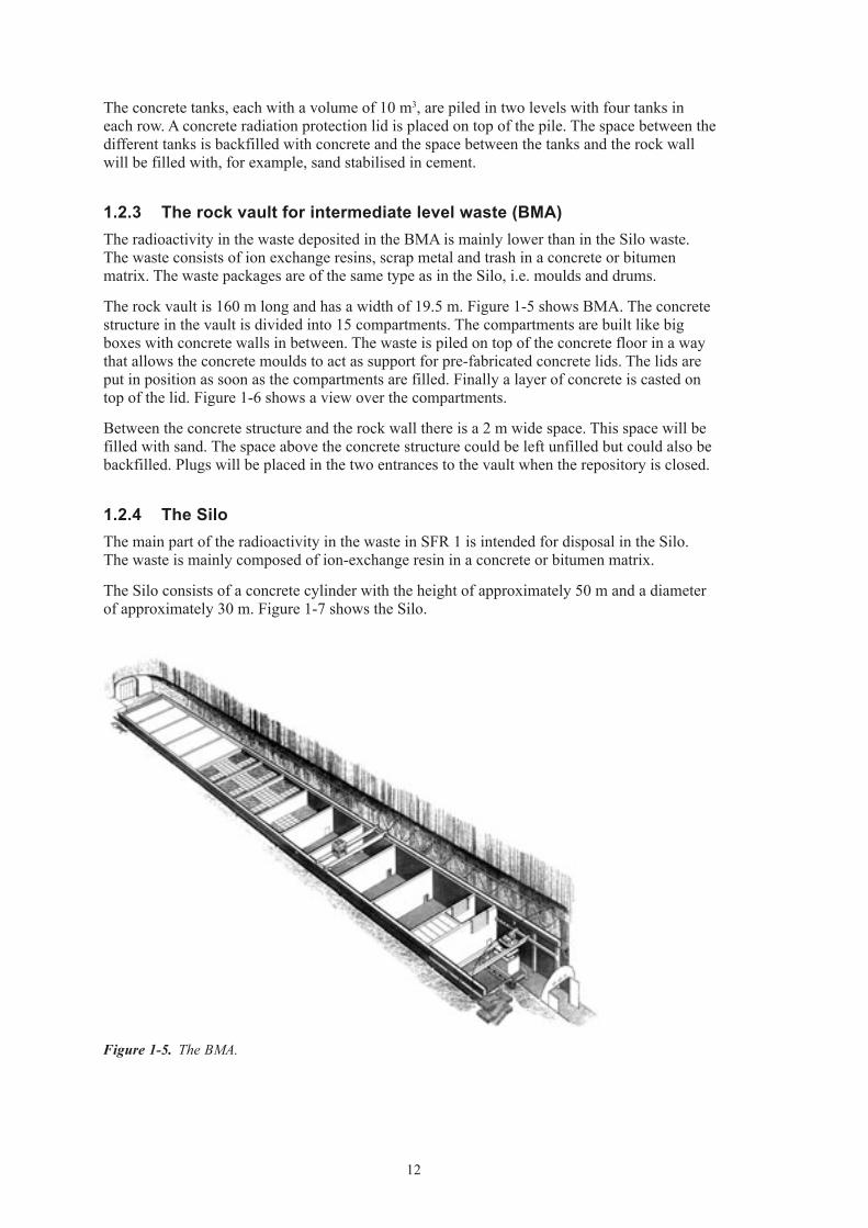
1.2.3 The rock vault for intermediate level waste (BMA)The radioactivity in the waste deposited in the BMA is mainly lower than in the Silo waste. The waste consists of ion exchange resins, scrap metal and trash in a concrete or bitumen matrix. The waste packages are of the same type as in the Silo, i.e. moulds and drums.
The rock vault is 160 m long and has a width of 19.5 m. Figure 1-5 shows BMA. The concrete structure in the vault is divided into 15 compartments. The compartments are built like big boxes with concrete walls in between. The waste is piled on top of the concrete floor in a way that allows the concrete moulds to act as support for pre-fabricated concrete lids. The lids are put in position as soon as the compartments are filled. Finally a layer of concrete is casted on top of the lid. Figure 1-6 shows a view over the compartments.
Between the concrete structure and the rock wall there is a 2 m wide space. This space will be filled with sand. The space above the concrete structure could be left unfilled but could also be backfilled. Plugs will be placed in the two entrances to the vault when the repository is closed.
1.2.4 The SiloThe main part of the radioactivity in the waste in SFR 1 is intended for disposal in the Silo. The waste is mainly composed of ion-exchange resin in a concrete or bitumen matrix.
The Silo consists of a concrete cylinder with the height of approximately 50 m and a diameter of approximately 30 m. Figure 1-7 shows the Silo.
Figure 1‑5. The BMA.

13
Figure 1‑6. View over BMA.
Figure 1‑7. The Silo including some adjacent tunnels.

14
The Silo is divided into vertical shafts with intervening concrete walls. The waste packages are placed in the shafts, normally in levels with four moulds or 16 drums. The voids between the waste packages are gradually backfilled with porous concrete.
The walls of the Silo are made of reinforced concrete with a thickness of 0.8 m. In between the Silo walls and the surrounding rock there is a bentonite backfill, on average 1.2 m thick. The 1 m thick concrete floor in the bottom of the Silo is placed on a layer of 90/10 sand/bentonite mixture. According to present plans the top of the Silo will be a 1 m thick concrete lid. The top of the lid will be covered with a thin layer of sand and then 1.5 m of sand/bentonite mixture (90/10). The remaining void above the sand/bentonite in the top will be filled with sand or gravel or sand stabilised in cement.
1.3 Aim of the study and general assumptionsThe aim of this study is to present a waste inventory to be used as input to radionuclide release calculations and other kinds of calculation.
Three different inventories are presented. The inventory is based on the assumption that Swedish reactors will operate for 50 or 60 years, except Barsebäck 1 and 2 which closed in 1999 and 2005 respectively. The third inventory presented is one of a full repository (one part where it is assumed to be full with reference to radioactivity and one to volume). It is also assumed that future production of waste is produced with the methods foreseen today. No consideration has been taken to the future power upgrades.
Waste in the form of large components or waste having some other feature differentiating it from ‘normal’ waste is expected in SFR 1. In this study this waste is predicted to be deposited in BLA, 1BTF, 2BTF and BMA.
Furthermore, it is assumed that the majority of the Swedish power plants continue to use shallow land burial for their very low-level waste. Today Forsmark NPP, Oskarshamn NPP, Ringhals NPP and the Studsvik research site uses this method.
1.4 Structure of the reportThis report is divided in one main part and six appendices. The main part includes background, some common features for the waste and then a summary of all the waste, present and future, that is or will be deposited in the SFR 1.
The appendices are:
• AppendixA:Adescriptionofhowtheinventoryregardingnumberofwastepackageswas calculated.
• AppendixB:Adescriptionofhowtheinventoryregardingradionuclideswascalculated.
• AppendixC:AthoroughdescriptionofallwastetypesintheBLArockcavern.
• AppendixD:AthoroughdescriptionofallwastetypesintheBTFrockcaverns.
• AppendixE:AthoroughdescriptionofallwastetypesintheBMArockcavern.
• AppendixF:AthoroughdescriptionofallwastetypesintheSilo.
Appendix C–F includes geometry, materials, and radionuclide content for each waste type. Also, for each waste type a reference waste type is defined which is used in all kinds of calculations.

15
2 Waste packages in SFR 1 – general
2.1 The code system of waste in SFR – abbreviationsThe first Swedish commercial nuclear power plant (Oskarshamn 1) has been in operation since the early 70’s and consequently has produced waste since then. From the period before that, radioactive waste was produced during research and from the first test reactors. Most of that waste was dumped in the sea. The Swedish programme for final storage of the waste was not formed from the beginning, consequently the different power plants used different forms of treatment and also different forms of geometries, although the waste have some common fea-tures. In order to bring some systematic classification into the waste treatment, different waste types have been defined and a code system for these types has been developed. The system is very useful for data transfer between the power plants and the SFR facility.
The code system consists of one letter which denominates the producing plant, and two numbers giving information of what kind of raw waste, treatment method, geometry and in which part of the SFR the waste should be deposited. A complementary number (given after a ‘:’) could also be used to give information about some feature that differentiates this waste from others of the same kind.
For example the code R.01:9 means ion-exchange resins from the Ringhals NPP solidified in cement in a concrete package (mould) with the side 1.2×1.2×1.2 m. The waste is meant for disposal in the rock cavern for intermediate level waste (BMA). The ‘:9’ means that it is of an older type. In Table 2-1 and in Table 2-2 there are explanations of the different abbreviations.
Regarding the complimentary number the meaning is defined for each type, e.g. for B.05:2 the ‘:2’ means that it is drums in bad condition placed in a steel box. The only complementary number generally defined is ‘:9’ which means that it is of an older kind.
For each waste type there is a ‘waste type description’. This document includes descriptions of origin of the raw waste, the treatment process, interim storage at the site, transportation, handling in SFR and disposal in SFR. The document also includes the demands defined for each waste package regarding general features like ID-number and chemical, physical, radiological and mechanistic features and how to achieve them. This document is written by the waste producers and then approved first by SKB and then by the Swedish authorities. Before the document is approved, no disposal in SFR is allowed.
Table 2‑1. Abbreviations in the code system for the nuclear facilities in Sweden.
Aberration Nuclear power plant
B Barsebäck NPPC Clab (central interim fuel storage)F Forsmark NPPO Oskarshamn NPPR Ringhals NPPS Studsvik Research Site

16
2.2 Waste containers and matricesAs seen in the previous part, the waste packages in SFR are of many different kinds, but the containers and the waste matrices, i.e. treatment methods, are quite similar.
The containers are basically of six different kinds:
• Steeldrums.Standard200-litredrums.Themeasuresdifferabitbutthedrumsareapproxi-mately 90 cm high and have a diameter of 60 cm. In the BMA and the silo the drums are handled four by four put on a steel plate or in a steel box. Both types are custom made for the system. In the BTF the drums are handled one by one.
• Concretemoulds.Aconcretecubewiththeside1.2m.Thewallsusuallyhaveathicknessof 10 cm, but 25 cm and 35 cm can occur. The moulds are deposited in the BMA and in the Silo. Moulds with low dose rate are used to build stabilisation walls in 1BTF.
• Steelmoulds.Steelcubeswiththesameouterdimensionsastheconcretemouldbutwithjust 5 or 6 mm thick walls. The steel moulds have room for more than 70% more waste than the concrete ones but with considerably less radiation shielding properties. The steel moulds are used in BMA and the Silo.
• Concretetanks.Thesetankshavethelengthof3.3m,widthof1.3mandheightof2.3m.The walls are 15 cm thick. The container has a de-watering system in the bottom of the tank. The tank is used in 1BTF and 2BTF.
Table 2‑2. Abbreviations in the code system for treatment etc.
Aberration Disposal in Raw waste Geometry Treatment
01 BMA Ion-exchange resin Concrete mould Cement solidification02 Silo Ion-exchange resin Concrete mould Cement solidification03 –04 Silo Ion-exchange resin Steel drum Cement solidification05 BMA Ion-exchange resin Steel drum Bitumen stabilisation06 Silo Ion-exchange resin Steel drum Bitumen stabilisation07 BTF Ion-exchange resin Concrete tank De-watering08 – – – –09 BMA Sludge Steel drum Cement solidification10 BMA Sludge Concrete mould Cement solidification11 Silo Sludge Concrete mould Cement solidification12 BLA Scrap metal and refuse ISO-container –13 BTF Ashes Steel drum Cement stabilisation14 BLA Scrap metal and refuse ISO-container Cement stabilisation15 BMA Ion-exchange resin Steel mould Cement solidification16 Silo Ion-exchange resin Steel mould Cement solidification17 BMA Ion-exchange resin Steel mould Bitumen stabilisation18 Silo Ion-exchange resin Steel mould Bitumen stabilisation19 BTF Graphite Steel box –20 BLA Ion-exchange resins ISO-container Bitumen stabilised drums21 BMA Scrap metal and refuse Steel drum Cement stabilisation22 Silo Scrap metal and refuse Steel drum Cement stabilisation23 BMA Scrap metal and refuse Mould Cement stabilisation24 Silo Scrap metal and refuse Concrete mould Cement stabilisation29 BMA Evaporator concentrate Concrete mould Cement solidification99 All caverns Odd waste Differs Differs

17
• ISO-containers.Standardcontainers,usuallywiththedimensions6.4×2.4×1.3mbutotherdimensions can also be used. The containers can hold drums, boxes or bales. There can also be no inner package, just piled scrap metal. The containers are used in the BLA.
• Steelboxes.TheseboxesareprimarilyusedinsidetheISO-containers.
• ‘Odd’Waste.Largecomponentsasheatexchangersetccouldbeofinteresttodisposeofin SFR 1. In this report the packages are assumed to be made of steel and concrete where the geometry is like an ISO-container, a concrete tank or a mould depending on which rock vault they are supposed to be placed.
The different treatment methods are:
• Cementsolidification.Ion-exchangeresinsorsludgearemixedwithconcreteindrumsormoulds.
• Cementstabilisation.Scrapmetalandrefuseareplacedinmouldsandcementispouredoverit. Types 13 and 14 are a bit different. The waste is placed in 100-litre drums, which are then put inside standard 200-litre drums. Concrete is then poured in-between the drums.
• Bitumenstabilisation.Ion-exchangeresinsaredriedandmixedwithbitumenandthenpoured into moulds or drums.
• De-watering.Wetion-exchangeresinispumpedintoaconcretetankandwaterisremovedby suction.

19
3 Description of waste in BLA
This chapter is a short summary of Appendix C.
3.1 Waste packages in BLAThe BLA is designed mainly to contain scrap metals and refuse. All waste in BLA is handled in ISO-containers. As stated in the previous chapter the containers can hold different smaller pack-ages like drums, boxes and bales. One special type is type 20 (B.20 and F.20). These containers hold drums with bituminised ion-exchange resins.
3.2 Amount of waste in BLAThe number of the different waste types used in the inventory calculations is presented in Table 3-1. How the numbers has been estimated is presented in Appendix A.
From the number of waste packages and the reference waste type one can derive the sum-marised amounts of different materials in the BLA, see Table 3-2a–c.
Table 3‑1. Number of different waste packages in BLA at the time of closure for the four scenarios.
Waste type Number of packages Year 2040
Number of packages Year 2050
Number of packages Full Repository*
B.12 238 238 238B.20 12 12 12F.12 39 44 42F.20 15 15 15O.12 34 44 39O.99 5 5 5R.12 137 167 152S.12 45 45 45S.14 75 75 75
*) With respect to volume.

20
Table 3‑2a. Summarised amounts of different materials in BLA at the time of closure, year 2040.
Material Weight (kg) Area (m2)*
Iron/Steel 3.78E+06 2.20E+05Aluminium 5.58E+04 8.36E+03Cellulose (wood, paper, cloth) 4.33E+05Other organic (plastics, rubber, cable) 1.48E+06Other inorganic (insulation etc) 1.05E+05Ion-exchange Resin 9.77E+04Bitumen 1.17E+05
* ‘Area’ means the area exposed to ground water after closure of SFR 1.
Table 3‑2b. Summarised amounts of different materials in BLA at the time of closure, year 2050.
Material Weight (kg) Area (m2)*
Iron/Steel 4.07E+06 2.36E+05Aluminium 6.73E+04 9.95E+03Cellulose (wood, paper, cloth) 4.68E+05Other organic (plastics, rubber, cable) 1.62E+06Other inorganic (insulation etc) 1.05E+05Ion-exchange Resin 9.77E+04Bitumen 1.17E+05
* ‘Area’ means the area exposed to ground water after closure of SFR 1.
Table 3‑2c. Summarised amounts of different materials in BLA at the time of closure, full inventory**.
Material Weight (kg) Area (m2)*
Iron/Steel 3.92E+06 2.28E+05Aluminium 6.50E+04 9.60E+03Cellulose (wood, paper, cloth) 4.50E+05Other organic (plastics, rubber, cable) 1.55E+06Other inorganic (insulation etc) 1.05E+05Ion-exchange Resin 9.77E+04Bitumen 1.17E+05
* ‘Area’ means the area exposed to ground water after closure of SFR 1.
** Regarding volume.

21
3.3 Radionuclide inventory in BLAThe inventory of radionuclides in BLA is presented in Table 3-3. How the amounts of different radionuclides have been calculated is presented in Appendix B.
Table 3‑3. Summarised amounts of different radionuclides in BLA at the time of closure for the three scenarios.
Nuclide Activity (Bq) Year 2040
Activity (Bq) Year 2050
Activity (Bq) Full inventory*
H-3 2.2E+07 1.9E+07 1.5E+08Be-10 8.1E+02 9.2E+02 5.6E+03C-14 org 1.2E+09 1.4E+09 8.0E+09C-14 inorg 2.7E+09 3.3E+09 1.9E+10C-14 tot 3.9E+09 4.7E+09 2.7E+10Cl-36 1.0E+06 1.2E+06 7.2E+06Fe-55 4.2E+09 4.0E+09 2.9E+10Ni-59 5.3E+09 6.1E+09 3.7E+10Co-60 3.6E+10 3.1E+10 2.5E+11Ni-63 6.6E+11 7.7E+11 4.6E+12Se-79 4.9E+05 5.1E+05 3.4E+06Sr-90 4.7E+09 3.9E+09 3.3E+10Mo-93 2.0E+07 2.7E+07 1.4E+08Nb-93m 3.2E+08 3.0E+08 2.2E+09Zr-93 4.3E+06 5.1E+06 3.0E+07Nb-94 1.3E+07 1.5E+07 9.2E+07Tc-99 5.0E+08 6.4E+08 3.5E+09Ru-106 3.1E+03 3.1E+03 2.2E+04Pd-107 1.2E+05 1.3E+05 8.6E+05Ag-108m 4.2E+08 4.2E+08 2.9E+09Cd-113m 1.1E+07 7.3E+06 7.4E+07Sb-125 3.1E+08 2.9E+08 2.1E+09Sn-126 6.2E+04 6.3E+04 4.3E+05I-129 3.1E+05 3.3E+05 2.2E+06Ba-133 1.7E+06 1.5E+06 1.2E+07Cs-134 2.5E+07 1.8E+07 1.7E+08Cs-135 2.0E+06 2.1E+06 1.4E+07Cs-137 4.8E+10 4.1E+10 3.4E+11Pm-147 1.0E+08 7.4E+07 7.0E+08Sm-151 2.7E+08 2.6E+08 1.9E+09Eu-152 1.1E+09 6.5E+08 7.5E+09Eu-154 7.5E+08 4.4E+08 5.2E+09Eu-155 8.1E+07 4.6E+07 5.6E+08Ho-166m 1.7E+07 2.0E+07 1.2E+08U-232 6.0E+02 5.7E+02 4.1E+03U-234 3.0E+04 3.1E+04 2.1E+05U-235 4.3E+08 4.3E+08 3.0E+09U-236 9.0E+03 9.4E+03 6.2E+04Np-237 2.7E+04 2.8E+04 1.9E+05Pu-238 4.7E+07 4.6E+07 3.3E+08U-238 1.4E+09 1.4E+09 9.9E+09

22
Nuclide Activity (Bq) Year 2040
Activity (Bq) Year 2050
Activity (Bq) Full inventory*
Pu-239 1.3E+07 1.3E+07 9.1E+07Pu-240 2.6E+07 2.7E+07 1.8E+08Pu-241 4.8E+08 3.6E+08 3.4E+09Am-241 5.0E+07 5.3E+07 3.5E+08Am-242m 2.4E+05 2.4E+05 1.7E+06Pu-242 9.0E+04 9.4E+04 6.2E+05Am-243 9.0E+05 9.3E+05 6.2E+06Cm-243 2.3E+05 2.0E+05 1.6E+06Cm-244 2.2E+07 1.9E+07 1.5E+08Cm-245 9.0E+03 9.3E+03 6.2E+04Cm-246 2.4E+03 2.5E+03 1.7E+04Tot 7.7E+11 8.7E+11 5.3E+12
* Regarding activity.

23
4 Description of waste in BTF
This chapter is a short summary of Appendix D.
4.1 Waste packages in BTFThe BTF is designed mainly to contain de-watered ion-exchange resins, but solidified resins and ashes are present too. All waste in BTF is handled in concrete tanks, moulds or drums.
When the drums containing ashes is placed in the 1BTF-cavern some sort of stabilising walls are necessary. Concrete tanks are placed alongside the rock walls and drums are then piled lying down between them. When six rows of drums have been piled, moulds are placed across the rock vault, see Figure 4-1 and Figure 4-2. Concrete is then poured over the drums in order to stabilise them.
4.2 Amount of waste in BTFThe number of the different waste types used in the inventory calculations is presented in Table 4-1a and b. How the numbers have been estimated is presented in Appendix A.
There are two rock caverns in SFR named BTF, i.e. 1BTF and 2BTF. There is a limited freedom to choose how to place the waste in the two caverns.
Figure 4‑1. Inplacement of drums in 1BTF.

24
Figure 4‑2. Wall of moulds across 1BTF.
Table 4‑1a. Number of different waste packages in BTF 1 at the time of closure for the three scenarios.
Waste type Number of packages Year 2040
Number of packages Year 2050
Number of packages Full Repository*
B.07 29 29 29O.01 28 28 28O.07 119 159 459O.99 20 20 20R.01 91 91 91R.10 4 4 4R.23 21 21 21R.99 1 1 1S.13 5,055 5,130 5,700
* With respect to volume.
Table 4‑2b. Number of different waste packages in BTF 2 at the time of closure for the three scenarios.
Waste type Number of packages Year 2040
Number of packages Year 2050
Number of packages Full Repository*
B.07 194 194 194F.99 18 18 18O.07 537 577 532O.99 20 20 20S.13 399 474 390
* With respect to volume.

25
In order to perform detailed calculations an estimated distribution of the waste packages is made. The main principles are:
• Wastealreadydepositedhasbeendistributedastheyareplacedwithasmallexceptionofsome odd waste.
• 2BTFcontainsconcretetankswithde-wateredion-exchangeresinsandoldsteamseparatorsfrom Forsmark.
• 1BTFcontainsashes,mouldswithsolidifiedwasteandconcretetanks.
• Asacrudesimplificationitisassumedthatallfuturewasteisdividedevenlybetweenthetwo caverns. This renders an uneven distribution between the two caverns since they do not contain the same amount of waste today, hence there is a somewhat askew distribution of both volume and radionuclide contents in these caluculations.
From the number of waste packages and the reference waste type one can derive the sum-marised amounts of different materials in the BTF, see Table 4-3a–c and Table 4-4a–c.
Table 4‑3a. Summarised amounts of different materials in 1BTF at the time of closure, year 2040.
Material Weight (kg) Area (m2)*
Iron/Steel 4.20E+05 4.54E+04Aluminium 3.00E+04 1.19E+04Ashes 1.48E+05Ion-exchange resin 1.77E+05Other organic 1.31E+04Other inorganic 4.65E+03Sludge 9.31E+03Cement and concrete 1.98E+06Cellulose 1.68E+03
* ‘Area’ means the area exposed to ground water after closure of SFR 1.
Table 4‑3b. Summarised amounts of different materials in 1BTF at the time of closure, year 2050.
Material Weight (kg) Area (m2)*
Iron/Steel 4.62E+05 4.78E+04Aluminium 3.05E+04 1.21E+04Ashes 1.53E+05Ion-exchange resin 2.17E+05Other organic 1.57E+04Other inorganic 6.15E+03Sludge 1.17E+04Cement and concrete 2.41E+06Cellulose 1.68E+03
* ‘Area’ means the area exposed to ground water after closure of SFR 1.

26
Table 4‑3c. Summarised amounts of different materials in 1BTF at the time of closure, full inventory**.
Material Weight (kg) Area (m2)*
Iron/Steel 7.79E+05 6.67E+04Aluminium 3.42E+04 1.42E+04Ashes 1.89E+05Ion-exchange resin 5.21E+05Other organic 3.58E+04Sludge 3.00E+04Other inorganic 1.76E+04Cement and concrete 5.68E+06Cellulose 1.68E+03
* ‘Area’ means the area exposed to ground water after closure of SFR 1. ** regarding volume.
Table 4‑4a. Summarised amounts of different materials in 2BTF at the time of closure, year 2040.
Material Weight (kg) Area (m2)*
Iron/Steel 6.39E+05 3.72E+04Aluminium 2.59E+03 1.44E+03Ashes 2.53E+04Ion-exchange resin 8.11E+05Other organic 6.03E+04Other inorganic 4.65E+03Sludge 4.38E+04Cement and concrete 3.75E+06Cellulose 1.66E+02
* ‘Area’ means the area exposed to ground water after closure of SFR 1.
Table 4‑4b. Summarised amounts of different materials in 2BTF at the time of closure, year 2050.
Material Weight (kg) Area (m2)*
Iron/Steel 6.81E+05 3.96E+04Aluminium 3.08E+03 1.71E+03Ashes 3.01E+04Ion-exchange resin 8.51E+05Other organic 6.29E+04Other inorganic 6.15E+03Sludge 4.62E+04Cement and concrete 4.18E+06Cellulose 1.66E+02
* ‘Area’ means the area exposed to ground water after closure of SFR 1.

27
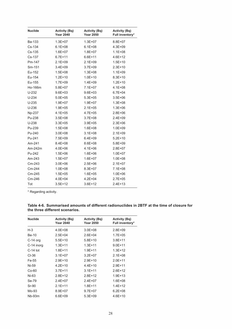
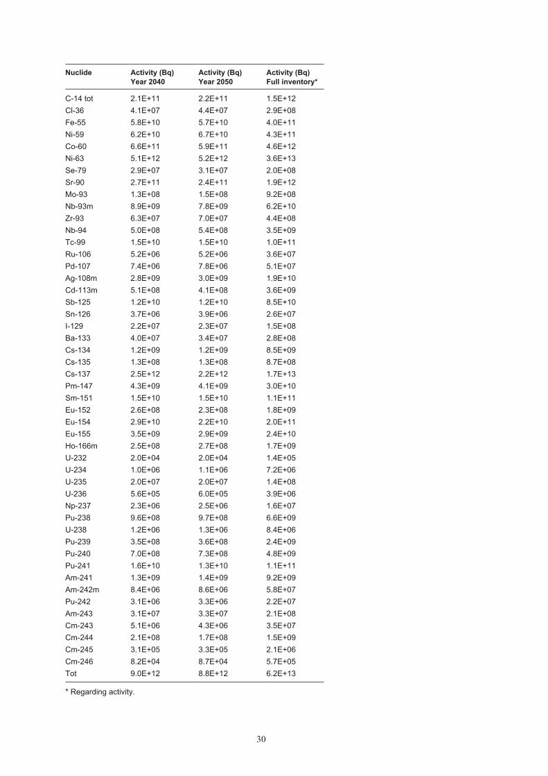
4.3 Radionuclide inventory in BTFThe inventories of radionuclides in BTF 1 and BTF 2 are presented in Table 4-5 and Table 4-6. Table 4-7 shows a summarised amount of different radionuclides in 1BTF and 2BTF as a sum. How the amounts of different radionuclides have been calculated is presented in Appendix B.
Table 4‑5. Summarised amounts of different radionuclides in 1BTF at the time of closure for the three different scenarios.
Nuclide Activity (Bq) Year 2040
Activity (Bq) Year 2050
Activity (Bq) Full inventory*
H-3 1.6E+08 1.7E+08 1.1E+09Be-10 5.1E+03 6.4E+03 3.5E+04C-14 org 7.4E+09 9.5E+09 5.1E+10C-14 inorg 1.7E+10 2.2E+10 1.2E+11C-14 tot 2.5E+10 3.2E+10 1.7E+11Cl-36 1.1E+07 1.2E+07 7.3E+07Fe-55 2.9E+10 2.9E+10 2.0E+11Ni-59 2.1E+10 2.3E+10 1.4E+11Co-60 2.9E+11 2.9E+11 2.0E+12Ni-63 2.3E+12 2.4E+12 1.6E+13Se-79 5.9E+06 6.7E+06 4.1E+07Sr-90 6.4E+10 6.4E+10 4.5E+11Mo-93 4.4E+07 5.2E+07 3.1E+08Nb-93m 2.3E+09 2.5E+09 1.6E+10Zr-93 1.5E+07 1.8E+07 1.0E+08Nb-94 8.5E+07 1.1E+08 5.9E+08Tc-99 7.0E+09 7.4E+09 4.8E+10Ru-106 2.6E+06 2.6E+06 1.8E+07Pd-107 1.5E+06 1.7E+06 1.0E+07Ag-108m 4.8E+08 6.0E+08 3.4E+09Cd-113m 1.8E+08 1.6E+08 1.2E+09Sb-125 6.1E+09 6.1E+09 4.2E+10Sn-126 7.4E+05 8.4E+05 5.2E+06I-129 3.1E+06 3.6E+06 2.1E+07
Table 4‑4c. Summarised amounts of different materials in 2BTF at the time of closure, full inventory**.
Material Weight (kg) Area (m2)*
Iron/Steel 6.34E+05 3.69E+04Aluminium 2.54E+03 1.40E+03Ashes 2.48E+04Ion-exchange resin 8.06E+05Other organic 6.00E+04Sludge 4.35E+04Other inorganic 4.47E+03Cement and concrete 3.70E+06Cellulose 1.66E+02
* ‘Area’ means the area exposed to ground water after closure of SFR 1.
** Regarding volume.
28
Nuclide Activity (Bq) Year 2040
Activity (Bq) Year 2050
Activity (Bq) Full inventory*
Ba-133 1.3E+07 1.3E+07 8.8E+07Cs-134 6.1E+08 6.1E+08 4.3E+09Cs-135 1.6E+07 1.8E+07 1.1E+08Cs-137 6.7E+11 6.6E+11 4.6E+12Pm-147 2.1E+09 2.1E+09 1.5E+10Sm-151 3.4E+09 3.7E+09 2.3E+10Eu-152 1.5E+08 1.3E+08 1.1E+09Eu-154 1.2E+10 1.0E+10 8.3E+10Eu-155 1.7E+09 1.4E+09 1.2E+10Ho-166m 5.8E+07 7.1E+07 4.1E+08U-232 9.6E+03 9.6E+03 6.7E+04U-234 5.0E+05 5.3E+05 3.5E+06U-235 1.9E+07 1.9E+07 1.3E+08U-236 1.9E+05 2.1E+05 1.3E+06Np-237 4.1E+05 4.7E+05 2.8E+06Pu-238 3.5E+08 3.7E+08 2.4E+09U-238 3.3E+05 3.9E+05 2.3E+06Pu-239 1.5E+08 1.6E+08 1.0E+09Pu-240 3.0E+08 3.1E+08 2.1E+09Pu-241 7.5E+09 6.4E+09 5.2E+10Am-241 8.4E+08 8.6E+08 5.8E+09Am-242m 4.0E+06 4.1E+06 2.8E+07Pu-242 1.5E+06 1.6E+06 1.0E+07Am-243 1.5E+07 1.6E+07 1.0E+08Cm-243 3.0E+06 2.5E+06 2.1E+07Cm-244 1.0E+08 8.3E+07 7.1E+08Cm-245 1.5E+05 1.6E+05 1.0E+06Cm-246 4.0E+04 4.2E+04 2.7E+05Tot 3.5E+12 3.6E+12 2.4E+13
* Regarding activity.
Table 4‑6. Summarised amounts of different radionuclides in 2BTF at the time of closure for the three different scenarios.
Nuclide Activity (Bq) Year 2040
Activity (Bq) Year 2050
Activity (Bq) Full inventory*
H-3 4.0E+08 3.0E+08 2.8E+09Be-10 2.5E+04 2.6E+04 1.7E+05C-14 org 5.5E+10 5.8E+10 3.8E+11C-14 inorg 1.3E+11 1.3E+11 9.0E+11C-14 tot 1.8E+11 1.9E+11 1.3E+12Cl-36 3.1E+07 3.2E+07 2.1E+08Fe-55 2.9E+10 2.9E+10 2.0E+11Ni-59 4.2E+10 4.4E+10 2.9E+11Co-60 3.7E+11 3.1E+11 2.6E+12Ni-63 2.8E+12 2.8E+12 1.9E+13Se-79 2.4E+07 2.4E+07 1.6E+08Sr-90 2.1E+11 1.8E+11 1.4E+12Mo-93 8.9E+07 9.7E+07 6.2E+08Nb-93m 6.6E+09 5.3E+09 4.6E+10

29
Nuclide Activity (Bq) Year 2040
Activity (Bq) Year 2050
Activity (Bq) Full inventory*
Zr-93 4.8E+07 5.1E+07 3.3E+08Nb-94 4.2E+08 4.4E+08 2.9E+09Tc-99 7.6E+09 8.1E+09 5.3E+10Ru-106 2.6E+06 2.6E+06 1.8E+07Pd-107 5.9E+06 6.1E+06 4.1E+07Ag-108m 2.3E+09 2.4E+09 1.6E+10Cd-113m 3.4E+08 2.6E+08 2.3E+09Sb-125 6.2E+09 6.1E+09 4.3E+10Sn-126 2.9E+06 3.0E+06 2.0E+07I-129 1.9E+07 1.9E+07 1.3E+08Ba-133 2.8E+07 2.1E+07 1.9E+08Cs-134 6.1E+08 6.1E+08 4.3E+09Cs-135 1.1E+08 1.1E+08 7.6E+08Cs-137 1.8E+12 1.6E+12 1.3E+13Pm-147 2.1E+09 2.1E+09 1.5E+10Sm-151 1.2E+10 1.1E+10 8.2E+10Eu-152 1.1E+08 1.0E+08 7.4E+08Eu-154 1.7E+10 1.2E+10 1.2E+11Eu-155 1.8E+09 1.5E+09 1.2E+10Ho-166m 1.9E+08 2.0E+08 1.3E+09U-232 1.1E+04 1.0E+04 7.4E+04U-234 5.4E+05 5.7E+05 3.7E+06U-235 7.5E+05 8.5E+05 5.2E+06U-236 3.7E+05 3.9E+05 2.6E+06Np-237 1.9E+06 2.0E+06 1.3E+07Pu-238 6.0E+08 6.0E+08 4.2E+09U-238 8.8E+05 9.4E+05 6.1E+06Pu-239 2.0E+08 2.1E+08 1.4E+09Pu-240 4.0E+08 4.1E+08 2.8E+09Pu-241 8.6E+09 7.0E+09 6.0E+10Am-241 4.9E+08 5.1E+08 3.4E+09Am-242m 4.4E+06 4.5E+06 3.0E+07Pu-242 1.6E+06 1.7E+06 1.1E+07Am-243 1.6E+07 1.7E+07 1.1E+08Cm-243 2.0E+06 1.8E+06 1.4E+07Cm-244 1.1E+08 9.0E+07 7.8E+08Cm-245 1.6E+05 1.7E+05 1.1E+06Cm-246 4.3E+04 4.5E+04 3.0E+05Tot 5.5E+12 5.2E+12 3.8E+13
* Regarding activity.
Table 4‑7. Summarised amounts of different radionuclides in BTF (sum of 1BTF and 2BTF) at the time of closure for the three different scenarios.
Nuclide Activity (Bq) Year 2040
Activity (Bq) Year 2050
Activity (Bq) Full inventory*
H-3 5.6E+08 4.8E+08 3.9E+09Be-10 3.0E+04 3.3E+04 2.1E+05C-14 org 6.3E+10 6.7E+10 4.4E+11C-14 inorg 1.5E+11 1.6E+11 1.0E+12
30
Nuclide Activity (Bq) Year 2040
Activity (Bq) Year 2050
Activity (Bq) Full inventory*
C-14 tot 2.1E+11 2.2E+11 1.5E+12Cl-36 4.1E+07 4.4E+07 2.9E+08Fe-55 5.8E+10 5.7E+10 4.0E+11Ni-59 6.2E+10 6.7E+10 4.3E+11Co-60 6.6E+11 5.9E+11 4.6E+12Ni-63 5.1E+12 5.2E+12 3.6E+13Se-79 2.9E+07 3.1E+07 2.0E+08Sr-90 2.7E+11 2.4E+11 1.9E+12Mo-93 1.3E+08 1.5E+08 9.2E+08Nb-93m 8.9E+09 7.8E+09 6.2E+10Zr-93 6.3E+07 7.0E+07 4.4E+08Nb-94 5.0E+08 5.4E+08 3.5E+09Tc-99 1.5E+10 1.5E+10 1.0E+11Ru-106 5.2E+06 5.2E+06 3.6E+07Pd-107 7.4E+06 7.8E+06 5.1E+07Ag-108m 2.8E+09 3.0E+09 1.9E+10Cd-113m 5.1E+08 4.1E+08 3.6E+09Sb-125 1.2E+10 1.2E+10 8.5E+10Sn-126 3.7E+06 3.9E+06 2.6E+07I-129 2.2E+07 2.3E+07 1.5E+08Ba-133 4.0E+07 3.4E+07 2.8E+08Cs-134 1.2E+09 1.2E+09 8.5E+09Cs-135 1.3E+08 1.3E+08 8.7E+08Cs-137 2.5E+12 2.2E+12 1.7E+13Pm-147 4.3E+09 4.1E+09 3.0E+10Sm-151 1.5E+10 1.5E+10 1.1E+11Eu-152 2.6E+08 2.3E+08 1.8E+09Eu-154 2.9E+10 2.2E+10 2.0E+11Eu-155 3.5E+09 2.9E+09 2.4E+10Ho-166m 2.5E+08 2.7E+08 1.7E+09U-232 2.0E+04 2.0E+04 1.4E+05U-234 1.0E+06 1.1E+06 7.2E+06U-235 2.0E+07 2.0E+07 1.4E+08U-236 5.6E+05 6.0E+05 3.9E+06Np-237 2.3E+06 2.5E+06 1.6E+07Pu-238 9.6E+08 9.7E+08 6.6E+09U-238 1.2E+06 1.3E+06 8.4E+06Pu-239 3.5E+08 3.6E+08 2.4E+09Pu-240 7.0E+08 7.3E+08 4.8E+09Pu-241 1.6E+10 1.3E+10 1.1E+11Am-241 1.3E+09 1.4E+09 9.2E+09Am-242m 8.4E+06 8.6E+06 5.8E+07Pu-242 3.1E+06 3.3E+06 2.2E+07Am-243 3.1E+07 3.3E+07 2.1E+08Cm-243 5.1E+06 4.3E+06 3.5E+07Cm-244 2.1E+08 1.7E+08 1.5E+09Cm-245 3.1E+05 3.3E+05 2.1E+06Cm-246 8.2E+04 8.7E+04 5.7E+05Tot 9.0E+12 8.8E+12 6.2E+13
* Regarding activity.

31
5 Description of waste in BMA
This chapter is a short summary of Appendix E.
5.1 Waste packages in BMAThe BMA is designed to contain intermediate level waste which have a lower dose rate or waste that of some kind of reason is not suitable to deposit in the Silo. The waste contains solidified (bitumen or cement) ion-exchange resins and stabilised scrap metal and refuses. All waste in BMA is handled in moulds or drums.
5.2 Amount of waste in BMAThe number of the different waste types is presented in Table 5-1. How the numbers has been estimated is presented in Appendix A.
From the number of waste packages and the reference waste type one can derive the sum-marised amounts of different materials in the BMA, see Table 5-2a–c.
Table 5‑1. Number of different waste types in BMA at the time of closure for the three scenarios.
Waste type Number of packages Year 2040
Number of packages Year 2050
Number of packages Full repository
B.05 4,188 4,188 4,188B.23 30 30 30C.01 68 68 68C.23 162 202 167F.05 1,712 1,712 1,712F.15 11 11 11F.17 1,305 1,605 1,343F.23 389 469 399F.99 2 2 2O.01 675 675 675O.23 570 640 579R.01 1,686 1,686 1,686R.10 126 146 129R.15 153 163 154R.23 558 608 564R.29 660 960 698S.09 880 1,080 905S.23 340 440 353

32
Table 5‑2a. Summarised amounts of different materials in BMA at the time of closure, year 2040.
Material Weight (kg) Area (m2)*
Iron/Steel 2.68E+06 1.24E+05Aluminium 7.09E+03 1.02E+03Cellulose (wood, paper, cloth) 1.44E+05Other organic (plastic, rubber, cable) 2.85E+05Other inorganic 3.43E+04Ion-exchange resin 1.63E+06Sludge 5.86E+04Evaporator bottoms 6.20E+05Bitumen 1.76E+06Cement and concrete 1.25E+07
* ‘Area’ means the area exposed to ground water after closure of SFR 1.
Table 5‑2b. Summarised amounts of different materials in BMA at the time of closure, year 2050.
Material Weight (kg) Area (m2)*
Iron/Steel 3.03E+06 1.38E+05Aluminium 8.43E+03 1.22E+03Cellulose (wood, paper, cloth) 1.65E+05Other organic (plastic, rubber, cable) 3.33E+05Other inorganic 4.32E+04Ion-exchange resin 1.83E+06Sludge 6.95E+04Evaporator bottoms 8.66E+05Bitumen 2.01E+06Cement and concrete 1.41E+07
* ‘Area’ means the area exposed to ground water after closure of SFR 1.
Table 5‑2c. Summarised amounts of different materials in BMA at the time of closure, full inventory**.
Material Weight (kg) Area (m2)*
Iron/Steel 2.76E+06 1.26E+05Aluminium 7.26E+03 1.05E+03Cellulose (wood, paper, cloth) 1.47E+05Other organic (plastic, rubber, cable) 2.91E+05Other inorganic 3.54E+04Ion-exchange resin 1.65E+06Sludge 6.00E+04Evaporator bottoms 6.51E+05Bitumen 1.79E+06Cement and concrete 1.27E+07
* ‘Area’ means the area exposed to ground water after closure of SFR 1.
** With regard to volume.

33
5.3 Radionuclide inventory in BMAThe inventory of radionuclides is presented in Table 5-3. How the amounts of different radio-nuclides have been calculated is presented in Appendix B.
Table 5‑3. Summarised amounts of different radionuclides in BMA at the time of closure for the three different scenarios.
Nuclide Activity (Bq) Year 2040
Activity (Bq) Year 2050
Activity (Bq) Full inventory*
H-3 3.8E+09 3.4E+09 2.6E+10Be-10 2.2E+05 2.3E+05 1.5E+06C-14 org 3.2E+11 3.4E+11 2.2E+12C-14 inorg 7.4E+11 8.0E+11 5.2E+12C-14 tot 1.1E+12 1.1E+12 7.4E+12Cl-36 2.3E+08 2.5E+08 1.6E+09Fe-55 1.5E+12 1.5E+12 1.0E+13Ni-59 2.1E+12 2.1E+12 1.4E+13Co-60 7.0E+12 6.8E+12 4.9E+13Ni-63 2.6E+14 2.6E+14 1.8E+15Se-79 2.1E+08 2.3E+08 1.5E+09Sr-90 1.7E+12 1.5E+12 1.2E+13Mo-93 6.8E+08 7.5E+08 4.7E+09Nb-93m 5.9E+10 5.3E+10 4.1E+11Zr-93 4.2E+08 4.5E+08 2.9E+09Nb-94 3.6E+09 3.9E+09 2.5E+10Tc-99 3.7E+10 4.4E+10 2.6E+11Ru-106 1.2E+08 1.2E+08 8.1E+08Pd-107 5.4E+07 5.6E+07 3.7E+08Ag-108m 2.0E+10 2.1E+10 1.4E+11Cd-113m 3.7E+09 3.2E+09 2.5E+10Sb-125 1.5E+11 1.5E+11 1.1E+12Sn-126 2.7E+07 2.8E+07 1.9E+08I-129 1.8E+08 1.9E+08 1.3E+09Ba-133 2.8E+08 2.6E+08 2.0E+09Cs-134 7.0E+10 7.0E+10 4.8E+11Cs-135 1.0E+09 1.1E+09 7.2E+09Cs-137 2.0E+13 1.9E+13 1.4E+14Pm-147 1.6E+11 1.6E+11 1.1E+12Sm-151 1.1E+11 1.1E+11 7.6E+11Eu-152 4.0E+08 3.4E+08 2.8E+09Eu-154 2.3E+11 2.1E+11 1.6E+12Eu-155 4.7E+10 4.6E+10 3.3E+11Ho-166m 1.6E+09 1.8E+09 1.1E+10U-232 1.5E+05 1.5E+05 1.0E+06U-234 7.7E+06 8.3E+06 5.3E+07U-235 2.8E+06 3.2E+06 2.0E+07U-236 3.0E+06 3.2E+06 2.1E+07Np-237 2.5E+07 2.9E+07 1.7E+08Pu-238 9.6E+09 9.5E+09 6.7E+10U-238 6.2E+06 6.8E+06 4.3E+07

34
Nuclide Activity (Bq) Year 2040
Activity (Bq) Year 2050
Activity (Bq) Full inventory*
Pu-239 2.0E+09 2.0E+09 1.4E+10Pu-240 4.0E+09 4.1E+09 2.7E+10Pu-241 1.4E+11 1.3E+11 9.7E+11Am-241 6.9E+09 7.7E+09 4.8E+10Am-242m 6.2E+07 6.5E+07 4.3E+08Pu-242 2.3E+07 2.5E+07 1.6E+08Am-243 2.3E+08 2.5E+08 1.6E+09Cm-243 5.5E+07 5.3E+07 3.8E+08Cm-244 1.4E+09 1.2E+09 9.4E+09Cm-245 2.3E+06 2.5E+06 1.6E+07Cm-246 6.1E+05 6.6E+05 4.2E+06Tot 2.9E+14 3.0E+14 2.0E+15
* Regarding activity.
5.4 Inplacement of waste in BMAThe BMA cavern is the most complex regarding different waste, materials, placement of pack-ages and so on. The cavern also contains a fair part (approximately 6%) of the total inventory of radionuclides.
The distribution as of December 2006 is shown as it is. Future deposition will be made to get an even distribution of radioactivity throughout the entire cavern.
Table 5-5 shows the distribution of the different waste types in the different compartments in the BMA until 31 December 2006.

35
Table 5‑5. Distribution of waste in the different compartments in the BMA until 31 December 2006.
Waste type Package Matrix Compartment
1 2 3 4 5 6 7 8 9 10 11 12 13 14 15 Total
B.05 drum bitumen 1,168 2,000 176 3,344B.05:02 drum* bitumen 382 270 96 96 844B.23 mould cement 30 30C.01 mould cement 20 10 1 21 52C.23 mould cement 8 16 1 25F.05 drum cement 1,712 1,712F.15 mould cement 8 3 11F.17 mould bitumen 144 28 259 431F.23 mould cement 64 12 92 168F.99 mould cement 2 2O.01 mould cement 56 254 29 184 163 686O.23 mould cement 36 36 134 131 28 365R.01 mould cement 576 148 145 143 144 144 144 146 88 8 1,686R.10 mould cement 16 48 64R.15 mould cement 124 124R.23 mould cement 124 120 90 68 4 406R.29 mould cement 0S.09 drum cement 0S.23 drum cement 0Total 576 2,242 1,727 575 2,268 680 576 546 556 192 0 12 0 0 0 9,950
* Four drums are placed in one mould.
37
6 Description of waste in the Silo
This chapter is a short summary of Appendix F.
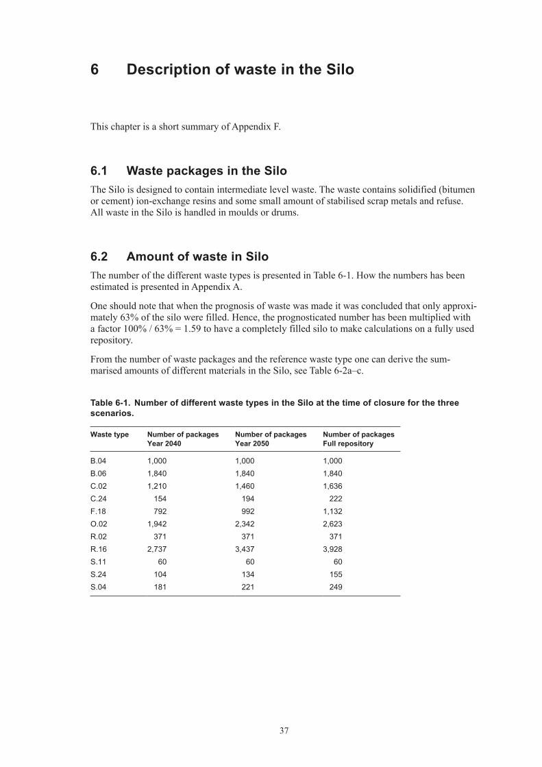
6.1 Waste packages in the SiloThe Silo is designed to contain intermediate level waste. The waste contains solidified (bitumen or cement) ion-exchange resins and some small amount of stabilised scrap metals and refuse. All waste in the Silo is handled in moulds or drums.
6.2 Amount of waste in SiloThe number of the different waste types is presented in Table 6-1. How the numbers has been estimated is presented in Appendix A.
One should note that when the prognosis of waste was made it was concluded that only approxi-mately 63% of the silo were filled. Hence, the prognosticated number has been multiplied with a factor 100% / 63% = 1.59 to have a completely filled silo to make calculations on a fully used repository.
From the number of waste packages and the reference waste type one can derive the sum-marised amounts of different materials in the Silo, see Table 6-2a–c.
Table 6‑1. Number of different waste types in the Silo at the time of closure for the three scenarios.
Waste type Number of packages Year 2040
Number of packages Year 2050
Number of packages Full repository
B.04 1,000 1,000 1,000B.06 1,840 1,840 1,840C.02 1,210 1,460 1,636C.24 154 194 222F.18 792 992 1,132O.02 1,942 2,342 2,623R.02 371 371 371R.16 2,737 3,437 3,928S.11 60 60 60S.24 104 134 155S.04 181 221 249

38
Table 6‑2a. Summarised amounts of different materials in Silo at the time of closure, year 2040.
Material Weight (kg) Area (m2) *
Iron/Steel 2.79E+06 1.22E+05Aluminium 4.02E+02 7.60E+01Cellulose (wood, paper, cloth) 5.57E+03Other organics (plastic, rubber, cable) 3.22E+04Other inorganics 1.91E+04Ion-exchange resins 1.80E+06Sludge 2.00E+04Bitumen 1.04E+06Cement and concrete 1.56E+07
* ‘Area’ means the area exposed to ground water after closure of SFR 1.
Table 6‑2b. Summarised amounts of different materials in Silo at the time of closure, year 2050.
Material Weight (kg) Area (m2) *
Iron/Steel 3.40E+06 1.48E+05Aluminium 5.18E+02 9.80E+01Cellulose (wood, paper, cloth) 6.97E+03Other organics (plastic, rubber, cable) 3.87E+04Other inorganics 2.42E+04Ion-exchange resins 2.18E+06Sludge 2.00E+04Bitumen 1.23E+06Cement and concrete 1.91E+07
* ‘Area’ means the area exposed to ground water after closure of SFR 1.
Table 6‑2c. Summarised amounts of different materials in Silo at the time of closure, full inventory**.
Material Weight (kg) Area (m2) *
Iron/Steel 3.83E+06 1.66E+05Aluminium 5.99E+02 1.13E+02Cellulose (wood, paper, cloth) 7.95E+03Other organics (plastic, rubber, cable) 4.32E+04Other inorganics 2.78E+04Ion-exchange resins 2.45E+06Sludge 2.00E+04Bitumen 1.36E+06Cement and concrete 2.16E+07
* ‘Area’ means the area exposed to ground water after closure of SFR 1.
** Regarding volume.

39
6.3 Radionuclide inventory in SiloThe inventory of radionuclides is presented in Table 6-3. How the amounts of different radio-nuclides have been calculated is presented in Appendix B.
Table 6‑3. Summarised amounts of different radionuclides in Silo at the time of closure for the three different scenarios.
Nuclide Activity (Bq) Year 2040
Activity (Bq) Year 2050
Activity (Bq) Full inventory*
H-3 3.5E+10 3.6E+10 2.4E+11Be-10 9.7E+05 1.2E+06 6.7E+06C-14 org 1.4E+12 1.7E+12 9.6E+12C-14 inorg 3.2E+12 4.0E+12 2.2E+13C-14 tot 4.6E+12 5.8E+12 3.2E+13Cl-36 1.1E+09 1.3E+09 7.5E+09Fe-55 2.0E+13 2.0E+13 1.4E+14Ni-59 7.3E+12 9.0E+12 5.1E+13Co-60 8.5E+13 8.5E+13 5.9E+14Ni-63 8.9E+14 1.1E+15 6.2E+15Se-79 1.0E+09 1.2E+09 7.1E+09Sr-90 1.1E+13 1.2E+13 7.5E+13Mo-93 2.9E+09 3.2E+09 2.0E+10Nb-93m 4.8E+11 5.0E+11 3.3E+12Zr-93 1.8E+09 2.2E+09 1.2E+10Nb-94 1.6E+10 2.0E+10 1.1E+11Tc-99 3.6E+11 4.6E+11 2.5E+12Ru-106 1.4E+09 1.4E+09 1.0E+10Pd-107 2.6E+08 3.0E+08 1.8E+09Ag-108m 9.2E+10 1.1E+11 6.4E+11Cd-113m 3.1E+10 3.2E+10 2.1E+11Sb-125 2.1E+12 2.1E+12 1.5E+13Sn-126 1.3E+08 1.5E+08 8.9E+08I-129 8.1E+08 9.3E+08 5.6E+09Ba-133 2.8E+09 2.9E+09 2.0E+10Cs-134 8.9E+11 8.9E+11 6.2E+12Cs-135 4.0E+09 4.4E+09 2.8E+10Cs-137 1.1E+14 1.2E+14 7.8E+14Pm-147 1.7E+12 1.7E+12 1.2E+13Sm-151 5.7E+11 6.5E+11 4.0E+12Eu-152 3.6E+09 3.7E+09 2.5E+10Eu-154 2.5E+12 2.5E+12 1.7E+13Eu-155 5.5E+11 5.5E+11 3.8E+12Ho-166m 7.0E+09 8.4E+09 4.9E+10U-232 5.7E+05 6.7E+05 4.0E+06U-234 2.6E+07 3.2E+07 1.8E+08U-235 1.4E+07 1.7E+07 9.8E+07U-236 1.0E+07 1.2E+07 7.2E+07Np-237 1.3E+08 1.6E+08 9.0E+08Pu-238 3.8E+10 4.5E+10 2.6E+11U-238 2.8E+07 3.4E+07 1.9E+08

40
Nuclide Activity (Bq) Year 2040
Activity (Bq) Year 2050
Activity (Bq) Full inventory*
Pu-239 8.9E+09 1.1E+10 6.2E+10Pu-240 1.8E+10 2.2E+10 1.2E+11Pu-241 6.6E+11 6.8E+11 4.6E+12Am-241 4.9E+11 4.8E+11 3.4E+12Am-242m 2.2E+08 2.7E+08 1.6E+09Pu-242 7.9E+07 9.6E+07 5.5E+08Am-243 8.4E+08 1.0E+09 5.8E+09Cm-243 2.3E+08 2.5E+08 1.6E+09Cm-244 8.5E+09 9.2E+09 5.9E+10Cm-245 7.9E+06 9.6E+06 5.5E+07Cm-246 2.1E+06 2.5E+06 1.5E+07Tot 1.1E+15 1.4E+15 7.9E+15
* Regarding activity.
6.4 Inplacement of waste in SiloThe Silo contains the majority (approximately 92%) of the total inventory of radionuclides.
In order to do so some kind of distribution of the waste packages had to be made. The main principles has been:
• Wastethatactuallyhavebeendepositedhaveofcoursebeendistributedastheyareplaced.
• Bitumenisedwasteisplacedinthecentreofthesilo.
41
7 Summary
This chapter summarises the waste amounts and the radionuclide inventory from Chapter 3 to 6.
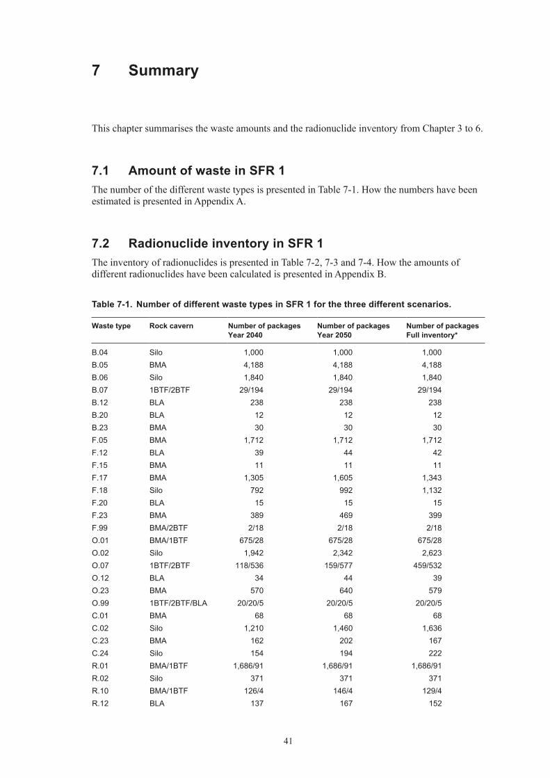
7.1 Amount of waste in SFR 1The number of the different waste types is presented in Table 7-1. How the numbers have been estimated is presented in Appendix A.
7.2 Radionuclide inventory in SFR 1The inventory of radionuclides is presented in Table 7-2, 7-3 and 7-4. How the amounts of different radionuclides have been calculated is presented in Appendix B.
Table 7‑1. Number of different waste types in SFR 1 for the three different scenarios.
Waste type Rock cavern Number of packages Year 2040
Number of packages Year 2050
Number of packages Full inventory*
B.04 Silo 1,000 1,000 1,000B.05 BMA 4,188 4,188 4,188B.06 Silo 1,840 1,840 1,840B.07 1BTF/2BTF 29/194 29/194 29/194B.12 BLA 238 238 238B.20 BLA 12 12 12B.23 BMA 30 30 30F.05 BMA 1,712 1,712 1,712F.12 BLA 39 44 42F.15 BMA 11 11 11F.17 BMA 1,305 1,605 1,343F.18 Silo 792 992 1,132F.20 BLA 15 15 15F.23 BMA 389 469 399F.99 BMA/2BTF 2/18 2/18 2/18O.01 BMA/1BTF 675/28 675/28 675/28O.02 Silo 1,942 2,342 2,623O.07 1BTF/2BTF 118/536 159/577 459/532O.12 BLA 34 44 39O.23 BMA 570 640 579O.99 1BTF/2BTF/BLA 20/20/5 20/20/5 20/20/5C.01 BMA 68 68 68C.02 Silo 1,210 1,460 1,636C.23 BMA 162 202 167C.24 Silo 154 194 222R.01 BMA/1BTF 1,686/91 1,686/91 1,686/91R.02 Silo 371 371 371R.10 BMA/1BTF 126/4 146/4 129/4R.12 BLA 137 167 152

42
Waste type Rock cavern Number of packages Year 2040
Number of packages Year 2050
Number of packages Full inventory*
R.15 BMA 153 163 154R.16 Silo 2,737 3,437 3,928R.23 BMA/1BTF 558/21 608/21 564/21R.29 BMA 660 960 697R.99 1BTF 1 1 1S.04 Silo 181 221 249S.09 BMA 880 1,080 905S.11 Silo 60 60 60S.12 BLA 45 45 45S.13 1BTF/2BTF 5,055/399 5,130/474 5,700/390S.14 BLA 75 75 75S.19 BTF 0 0 0S.21 BMA 0 0 0S.22 Silo 0 0 0S.23 BMA 340 440 352S.24 Silo 104 134 155Total 31,100 34,200 35,000
Table 7‑2. Summarised amounts of different radionuclides in SFR 1 at the time of closure (2040).
Nuclide Total (Bq) Silo (Bq) BMA (Bq) 1BTF (Bq) 2BTF (Bq) BLA (Bq)
H-3 3.9E+10 3.5E+10 3.8E+09 1.6E+08 4.0E+08 2.2E+07Be-10 1.2E+06 9.7E+05 2.2E+05 5.1E+03 2.5E+04 8.1E+02C-14 org 1.8E+12 1.4E+12 3.2E+11 7.4E+09 5.5E+10 1.2E+09C-14 inorg 4.1E+12 3.2E+12 7.4E+11 1.7E+10 1.3E+11 2.7E+09C-14 tot 5.9E+12 4.6E+12 1.1E+12 2.5E+10 1.8E+11 3.9E+09Cl-36 1.4E+09 1.1E+09 2.3E+08 1.1E+07 3.1E+07 1.0E+06Fe-55 2.1E+13 2.0E+13 1.5E+12 2.9E+10 2.9E+10 4.2E+09Ni-59 9.5E+12 7.3E+12 2.1E+12 2.1E+10 4.2E+10 5.3E+09Co-60 9.3E+13 8.5E+13 7.0E+12 2.9E+11 3.7E+11 3.6E+10Ni-63 1.2E+15 8.9E+14 2.6E+14 2.3E+12 2.8E+12 6.6E+11Se-79 1.3E+09 1.0E+09 2.1E+08 5.9E+06 2.4E+07 4.9E+05Sr-90 1.3E+13 1.1E+13 1.7E+12 6.4E+10 2.1E+11 4.7E+09Mo-93 3.7E+09 2.9E+09 6.8E+08 4.4E+07 8.9E+07 2.0E+07Nb-93m 5.5E+11 4.8E+11 5.9E+10 2.3E+09 6.6E+09 3.2E+08Zr-93 2.3E+09 1.8E+09 4.2E+08 1.5E+07 4.8E+07 4.3E+06Nb-94 2.0E+10 1.6E+10 3.6E+09 8.5E+07 4.2E+08 1.3E+07Tc-99 4.1E+11 3.6E+11 3.7E+10 7.0E+09 7.6E+09 5.0E+08Ru-106 1.6E+09 1.4E+09 1.2E+08 2.6E+06 2.6E+06 3.1E+03Pd-107 3.2E+08 2.6E+08 5.4E+07 1.5E+06 5.9E+06 1.2E+05Ag-108m 1.2E+11 9.2E+10 2.0E+10 4.8E+08 2.3E+09 4.2E+08Cd-113m 3.5E+10 3.1E+10 3.7E+09 1.8E+08 3.4E+08 1.1E+07Sb-125 2.3E+12 2.1E+12 1.5E+11 6.1E+09 6.2E+09 3.1E+08Sn-126 1.6E+08 1.3E+08 2.7E+07 7.4E+05 2.9E+06 6.2E+04I-129 1.0E+09 8.1E+08 1.8E+08 3.1E+06 1.9E+07 3.1E+05Ba-133 3.1E+09 2.8E+09 2.8E+08 1.3E+07 2.8E+07 1.7E+06Cs-134 9.6E+11 8.9E+11 7.0E+10 6.1E+08 6.1E+08 2.5E+07Cs-135 5.1E+09 4.0E+09 1.0E+09 1.6E+07 1.1E+08 2.0E+06

43
Nuclide Total (Bq) Silo (Bq) BMA (Bq) 1BTF (Bq) 2BTF (Bq) BLA (Bq)
Cs-137 1.3E+14 1.1E+14 2.0E+13 6.7E+11 1.8E+12 4.8E+10Pm-147 1.9E+12 1.7E+12 1.6E+11 2.1E+09 2.1E+09 1.0E+08Sm-151 7.0E+11 5.7E+11 1.1E+11 3.4E+09 1.2E+10 2.7E+08Eu-152 5.4E+09 3.6E+09 4.0E+08 1.5E+08 1.1E+08 1.1E+09Eu-154 2.8E+12 2.5E+12 2.3E+11 1.2E+10 1.7E+10 7.5E+08Eu-155 6.0E+11 5.5E+11 4.7E+10 1.7E+09 1.8E+09 8.1E+07Ho-166m 8.9E+09 7.0E+09 1.6E+09 5.8E+07 1.9E+08 1.7E+07U-232 7.5E+05 5.7E+05 1.5E+05 9.6E+03 1.1E+04 6.0E+02U-234 3.5E+07 2.6E+07 7.7E+06 5.0E+05 5.4E+05 3.0E+04U-235 4.7E+08 1.4E+07 2.8E+06 1.9E+07 7.5E+05 4.3E+08U-236 1.4E+07 1.0E+07 3.0E+06 1.9E+05 3.7E+05 9.0E+03Np-237 1.6E+08 1.3E+08 2.5E+07 4.1E+05 1.9E+06 2.7E+04Pu-238 4.9E+10 3.8E+10 9.6E+09 3.5E+08 6.0E+08 4.7E+07U-238 1.5E+09 2.8E+07 6.2E+06 3.3E+05 8.8E+05 1.4E+09Pu-239 1.1E+10 8.9E+09 2.0E+09 1.5E+08 2.0E+08 1.3E+07Pu-240 2.3E+10 1.8E+10 4.0E+09 3.0E+08 4.0E+08 2.6E+07Pu-241 8.2E+11 6.6E+11 1.4E+11 7.5E+09 8.6E+09 4.8E+08Am-241 5.0E+11 4.9E+11 6.9E+09 8.4E+08 4.9E+08 5.0E+07Am-242m 3.0E+08 2.2E+08 6.2E+07 4.0E+06 4.4E+06 2.4E+05Pu-242 1.1E+08 7.9E+07 2.3E+07 1.5E+06 1.6E+06 9.0E+04Am-243 1.1E+09 8.4E+08 2.3E+08 1.5E+07 1.6E+07 9.0E+05Cm-243 2.9E+08 2.3E+08 5.5E+07 3.0E+06 2.0E+06 2.3E+05Cm-244 1.0E+10 8.5E+09 1.4E+09 1.0E+08 1.1E+08 2.2E+07Cm-245 1.0E+07 7.9E+06 2.3E+06 1.5E+05 1.6E+05 9.0E+03Cm-246 2.8E+06 2.1E+06 6.1E+05 4.0E+04 4.3E+04 2.4E+03Tot 1.4E+15 1.1E+15 2.9E+14 3.5E+12 5.5E+12 7.7E+11
Table 7‑3. Summarised amounts of different radionuclides in SFR 1 at the time of closure (2050).
Nuclide Total (Bq) Silo (Bq) BMA (Bq) 1BTF (Bq) 2BTF (Bq) BLA (Bq)
H-3 4.0E+10 3.6E+10 3.4E+09 1.7E+08 3.0E+08 1.9E+07Be-10 1.4E+06 1.2E+06 2.3E+05 6.4E+03 2.6E+04 9.2E+02C-14 org 2.1E+12 1.7E+12 3.4E+11 9.5E+09 5.8E+10 1.4E+09C-14 inorg 5.0E+12 4.0E+12 8.0E+11 2.2E+10 1.3E+11 3.3E+09C-14 tot 7.1E+12 5.8E+12 1.1E+12 3.2E+10 1.9E+11 4.7E+09Cl-36 1.6E+09 1.3E+09 2.5E+08 1.2E+07 3.2E+07 1.2E+06Fe-55 2.1E+13 2.0E+13 1.5E+12 2.9E+10 2.9E+10 4.0E+09Ni-59 1.1E+13 9.0E+12 2.1E+12 2.3E+10 4.4E+10 6.1E+09Co-60 9.3E+13 8.5E+13 6.8E+12 2.9E+11 3.1E+11 3.1E+10Ni-63 1.4E+15 1.1E+15 2.6E+14 2.4E+12 2.8E+12 7.7E+11Se-79 1.5E+09 1.2E+09 2.3E+08 6.7E+06 2.4E+07 5.1E+05Sr-90 1.3E+13 1.2E+13 1.5E+12 6.4E+10 1.8E+11 3.9E+09Mo-93 4.2E+09 3.2E+09 7.5E+08 5.2E+07 9.7E+07 2.7E+07Nb-93m 5.7E+11 5.0E+11 5.3E+10 2.5E+09 5.3E+09 3.0E+08Zr-93 2.7E+09 2.2E+09 4.5E+08 1.8E+07 5.1E+07 5.1E+06Nb-94 2.4E+10 2.0E+10 3.9E+09 1.1E+08 4.4E+08 1.5E+07Tc-99 5.2E+11 4.6E+11 4.4E+10 7.4E+09 8.1E+09 6.4E+08Ru-106 1.6E+09 1.4E+09 1.2E+08 2.6E+06 2.6E+06 3.1E+03Pd-107 3.7E+08 3.0E+08 5.6E+07 1.7E+06 6.1E+06 1.3E+05

44
Nuclide Total (Bq) Silo (Bq) BMA (Bq) 1BTF (Bq) 2BTF (Bq) BLA (Bq)
Ag-108m 1.4E+11 1.1E+11 2.1E+10 6.0E+08 2.4E+09 4.2E+08Cd-113m 3.5E+10 3.2E+10 3.2E+09 1.6E+08 2.6E+08 7.3E+06Sb-125 2.3E+12 2.1E+12 1.5E+11 6.1E+09 6.1E+09 2.9E+08Sn-126 1.8E+08 1.5E+08 2.8E+07 8.4E+05 3.0E+06 6.3E+04I-129 1.1E+09 9.3E+08 1.9E+08 3.6E+06 1.9E+07 3.3E+05Ba-133 3.2E+09 2.9E+09 2.6E+08 1.3E+07 2.1E+07 1.5E+06Cs-134 9.7E+11 8.9E+11 7.0E+10 6.1E+08 6.1E+08 1.8E+07Cs-135 5.6E+09 4.4E+09 1.1E+09 1.8E+07 1.1E+08 2.1E+06Cs-137 1.4E+14 1.2E+14 1.9E+13 6.6E+11 1.6E+12 4.1E+10Pm-147 1.9E+12 1.7E+12 1.6E+11 2.1E+09 2.1E+09 7.4E+07Sm-151 7.7E+11 6.5E+11 1.1E+11 3.7E+09 1.1E+10 2.6E+08Eu-152 4.9E+09 3.7E+09 3.4E+08 1.3E+08 1.0E+08 6.5E+08Eu-154 2.7E+12 2.5E+12 2.1E+11 1.0E+10 1.2E+10 4.4E+08Eu-155 6.0E+11 5.5E+11 4.6E+10 1.4E+09 1.5E+09 4.6E+07Ho-166m 1.0E+10 8.4E+09 1.8E+09 7.1E+07 2.0E+08 2.0E+07U-232 8.4E+05 6.7E+05 1.5E+05 9.6E+03 1.0E+04 5.7E+02U-234 4.1E+07 3.2E+07 8.3E+06 5.3E+05 5.7E+05 3.1E+04U-235 4.7E+08 1.7E+07 3.2E+06 1.9E+07 8.5E+05 4.3E+08U-236 1.6E+07 1.2E+07 3.2E+06 2.1E+05 3.9E+05 9.4E+03Np-237 1.9E+08 1.6E+08 2.9E+07 4.7E+05 2.0E+06 2.8E+04Pu-238 5.5E+10 4.5E+10 9.5E+09 3.7E+08 6.0E+08 4.6E+07U-238 1.5E+09 3.4E+07 6.8E+06 3.9E+05 9.4E+05 1.4E+09Pu-239 1.3E+10 1.1E+10 2.0E+09 1.6E+08 2.1E+08 1.3E+07Pu-240 2.7E+10 2.2E+10 4.1E+09 3.1E+08 4.1E+08 2.7E+07Pu-241 8.3E+11 6.8E+11 1.3E+11 6.4E+09 7.0E+09 3.6E+08Am-241 4.9E+11 4.8E+11 7.7E+09 8.6E+08 5.1E+08 5.3E+07Am-242m 3.4E+08 2.7E+08 6.5E+07 4.1E+06 4.5E+06 2.4E+05Pu-242 1.2E+08 9.6E+07 2.5E+07 1.6E+06 1.7E+06 9.4E+04Am-243 1.3E+09 1.0E+09 2.5E+08 1.6E+07 1.7E+07 9.3E+05Cm-243 3.1E+08 2.5E+08 5.3E+07 2.5E+06 1.8E+06 2.0E+05Cm-244 1.1E+10 9.2E+09 1.2E+09 8.3E+07 9.0E+07 1.9E+07Cm-245 1.2E+07 9.6E+06 2.5E+06 1.6E+05 1.7E+05 9.3E+03Cm-246 3.3E+06 2.5E+06 6.6E+05 4.2E+04 4.5E+04 2.5E+03Tot 1.7E+15 1.4E+15 3.0E+14 3.6E+12 5.2E+12 8.7E+11
Table 7‑4. Summarised amounts of different radionuclides in SFR 1 at the time of closure (2040) at a full inventory regarding activity.
Nuclide Total (Bq) Silo (Bq) BMA (Bq) 1BTF (Bq) 2BTF (Bq) BLA (Bq)
H-3 2.7E+11 2.4E+11 2.6E+10 1.1E+09 2.8E+09 1.5E+08Be-10 8.4E+06 6.7E+06 1.5E+06 3.5E+04 1.7E+05 5.6E+03C-14 org 1.2E+13 9.6E+12 2.2E+12 5.1E+10 3.8E+11 8.0E+09C-14 inorg 2.9E+13 2.2E+13 5.2E+12 1.2E+11 9.0E+11 1.9E+10C-14 tot 4.1E+13 3.2E+13 7.4E+12 1.7E+11 1.3E+12 2.7E+10Cl-36 9.4E+09 7.5E+09 1.6E+09 7.3E+07 2.1E+08 7.2E+06Fe-55 1.5E+14 1.4E+14 1.0E+13 2.0E+11 2.0E+11 2.9E+10Ni-59 6.6E+13 5.1E+13 1.4E+13 1.4E+11 2.9E+11 3.7E+10Co-60 6.5E+14 5.9E+14 4.9E+13 2.0E+12 2.6E+12 2.5E+11Ni-63 8.0E+15 6.2E+15 1.8E+15 1.6E+13 1.9E+13 4.6E+12

45
Nuclide Total (Bq) Silo (Bq) BMA (Bq) 1BTF (Bq) 2BTF (Bq) BLA (Bq)
Se-79 8.8E+09 7.1E+09 1.5E+09 4.1E+07 1.6E+08 3.4E+06Sr-90 8.9E+13 7.5E+13 1.2E+13 4.5E+11 1.4E+12 3.3E+10Mo-93 2.6E+10 2.0E+10 4.7E+09 3.1E+08 6.2E+08 1.4E+08Nb-93m 3.8E+12 3.3E+12 4.1E+11 1.6E+10 4.6E+10 2.2E+09Zr-93 1.6E+10 1.2E+10 2.9E+09 1.0E+08 3.3E+08 3.0E+07Nb-94 1.4E+11 1.1E+11 2.5E+10 5.9E+08 2.9E+09 9.2E+07Tc-99 2.9E+12 2.5E+12 2.6E+11 4.8E+10 5.3E+10 3.5E+09Ru-106 1.1E+10 1.0E+10 8.1E+08 1.8E+07 1.8E+07 2.2E+04Pd-107 2.2E+09 1.8E+09 3.7E+08 1.0E+07 4.1E+07 8.6E+05Ag-108m 8.0E+11 6.4E+11 1.4E+11 3.4E+09 1.6E+10 2.9E+09Cd-113m 2.4E+11 2.1E+11 2.5E+10 1.2E+09 2.3E+09 7.4E+07Sb-125 1.6E+13 1.5E+13 1.1E+12 4.2E+10 4.3E+10 2.1E+09Sn-126 1.1E+09 8.9E+08 1.9E+08 5.2E+06 2.0E+07 4.3E+05I-129 7.0E+09 5.6E+09 1.3E+09 2.1E+07 1.3E+08 2.2E+06Ba-133 2.2E+10 2.0E+10 2.0E+09 8.8E+07 1.9E+08 1.2E+07Cs-134 6.7E+12 6.2E+12 4.8E+11 4.3E+09 4.3E+09 1.7E+08Cs-135 3.6E+10 2.8E+10 7.2E+09 1.1E+08 7.6E+08 1.4E+07Cs-137 9.4E+14 7.8E+14 1.4E+14 4.6E+12 1.3E+13 3.4E+11Pm-147 1.3E+13 1.2E+13 1.1E+12 1.5E+10 1.5E+10 7.0E+08Sm-151 4.9E+12 4.0E+12 7.6E+11 2.3E+10 8.2E+10 1.9E+09Eu-152 3.7E+10 2.5E+10 2.8E+09 1.1E+09 7.4E+08 7.5E+09Eu-154 1.9E+13 1.7E+13 1.6E+12 8.3E+10 1.2E+11 5.2E+09Eu-155 4.2E+12 3.8E+12 3.3E+11 1.2E+10 1.2E+10 5.6E+08Ho-166m 6.2E+10 4.9E+10 1.1E+10 4.1E+08 1.3E+09 1.2E+08U-232 5.2E+06 4.0E+06 1.0E+06 6.7E+04 7.4E+04 4.1E+03U-234 2.4E+08 1.8E+08 5.3E+07 3.5E+06 3.7E+06 2.1E+05U-235 3.2E+09 9.8E+07 2.0E+07 1.3E+08 5.2E+06 3.0E+09U-236 9.7E+07 7.2E+07 2.1E+07 1.3E+06 2.6E+06 6.2E+04Np-237 1.1E+09 9.0E+08 1.7E+08 2.8E+06 1.3E+07 1.9E+05Pu-238 3.4E+11 2.6E+11 6.7E+10 2.4E+09 4.2E+09 3.3E+08U-238 1.0E+10 1.9E+08 4.3E+07 2.3E+06 6.1E+06 9.9E+09Pu-239 7.8E+10 6.2E+10 1.4E+10 1.0E+09 1.4E+09 9.1E+07Pu-240 1.6E+11 1.2E+11 2.7E+10 2.1E+09 2.8E+09 1.8E+08Pu-241 5.7E+12 4.6E+12 9.7E+11 5.2E+10 6.0E+10 3.4E+09Am-241 3.5E+12 3.4E+12 4.8E+10 5.8E+09 3.4E+09 3.5E+08Am-242m 2.1E+09 1.6E+09 4.3E+08 2.8E+07 3.0E+07 1.7E+06Pu-242 7.3E+08 5.5E+08 1.6E+08 1.0E+07 1.1E+07 6.2E+05Am-243 7.6E+09 5.8E+09 1.6E+09 1.0E+08 1.1E+08 6.2E+06Cm-243 2.0E+09 1.6E+09 3.8E+08 2.1E+07 1.4E+07 1.6E+06Cm-244 7.0E+10 5.9E+10 9.4E+09 7.1E+08 7.8E+08 1.5E+08Cm-245 7.3E+07 5.5E+07 1.6E+07 1.0E+06 1.1E+06 6.2E+04Cm-246 1.9E+07 1.5E+07 4.2E+06 2.7E+05 3.0E+05 1.7E+04Tot 1.0E+16 7.9E+15 2.0E+15 2.4E+13 3.8E+13 5.3E+12
7.3 Toxic materialNo toxic material has been identified in SFR 1. Only small amounts of toxic material is allowed, e.g. lead, epoxi, asbestos.

47
8 Uncertainties
Three major uncertainties have been identified at a general level. Uncertainties in different waste types etc are described in the text in Appendices A–F.
The actual number of different waste packages is the first one. As in all prognosis there is a major uncertainty in what lays in the future. Not only the number of packages is uncertain there could also be other waste types or changes in the described types that occur in the future.
The amount of materials is calculated with a simple model, a reference waste package times a prognosis of waste packages. This means that the uncertainties are multiplied. One should keep in mind that the most materials come from waste types that are relatively common and therefore are the uncertainties smaller. No uncertainty analysis has been performed since it has been judged that what is in future waste overshadows all other uncertainties. The future uncertainty can not be quantified.
The radionuclides are estimated with correlation factors. The factors themselves include quite large uncertainties, but the method of correlation has weaknesses as well. For more discussion about correlation factors see Appendix A and references therein. A statistical quantification regarding the uncertainties for the correlation factors can be found in /Cronstrand 2005/. Further updates have been made on the subject and are presented in /Torstenfelt 2007/.

49
9 References
This reference list only includes references from the main report. References in the appendices are listed after each appendix (Appendices A–F).
SKB, 1993. Slutlig säkerhetsrapport för SFR 1 (in Swedish). Svensk Kärnbränslehantering AB, May 1993.
Cronstrand, 2005. Assessment of uncertainty to correlation factors. SKB R-05-76, Svensk Kärnbränslehantering AB.
Torstenfelt, 2007. Osäkerheter för radionuklider för deponering i SFR 1. Dok ID 1086802, version 3.0.

51
Appendix A
Calculation of waste amounts
1 Method of calculation 521.1 Aim of calculations – restrictions 521.2 Available information sources 521.3 Method of calculation 52
2 Waste amounts 552.1 Present amount 552.2 Future amount 562.3 Total future amount 57
3 Uncertainties 59
4 References 60

52
1 Method of calculation
1.1 Aim of calculations – restrictionsTo know the amounts of waste or rather the number of waste packages is not important in it self when you perform a safety assessment for a repository for radioactive waste. However, the number of waste packages is a fundamental parameter if you are to calculate the total amount of materials, radionuclides and chemicals. The aim of the calculations of waste amounts is to get a realistic estimate of the amounts of radio nuclides and materials and also their distribution in different parts of the SFR 1 repository.
There are always restrictions to a calculation; in this case it is of course the geometry of the repository. Also, as a starting point of the analysis we have assumed two different scenarios; that the Swedish reactors have a life span of 50 or 60 years and that they during these years produce waste that can and should be disposed of in SFR 1. Also we have assumed that the repository will be sealed in year 2040 or 2050 corresponding to a reactor life span of 50 and 60 years respectively.
1.2 Available information sourcesRadioactive waste has been produced in the Swedish nuclear power plants since the early 70’s. In the research facility Studsvik and other places production of radioactive waste took place earlier than the 70’s. The waste amounts produced through research to be disposed of in SFR 1 are small, if any, from the period before 1980. The SFR repository has been in operation since 1988. Hence, today there is an extensive experience regarding waste handling in Sweden. The sources to get information and data in this study are relatively few since the ones that are used are to be seen as thorough collections of data.
Information about waste that has already been disposed of in SFR has been taken from the operational database /Triumf 2007/ in SFR.
Regarding future amounts of different waste types the nuclear power plants and Clab and Studsvik have reported data for annual production /Johansson 2007/ and waste packages stored at the site. This information is stored in Prosit /Prosit 2007/.
1.3 Method of calculationAll calculations are performed by Prosit. In order to systemise the vast amounts of different sorts of waste Prosit uses the waste types described in the main report Section 2.1.
The calculations of the number of waste packages can be separated in two categories, existing waste and future waste.
Concerning existing waste Prosit extracts data from the operational database in SFR, Triumf. The number of existing waste packages in this inventory is the number of deposited packages 31 December 2006.
Concerning future waste, Prosit calculates the number of future packages of each waste type by multiplying the annual production with the number of remaining years of nuclear power plant operation and adding the packages stored on site.

53
The remaining years of operation has been estimated for the two different scenarios; 50 and 60 years operation. In the prognosis it is assumed that waste produced one year is delivered to SFR that same year. Since it is almost impossible to back track the different waste streams to a single reactor, an average of end of waste production per site has been calculated. The remaining time (in years) is then calculated as “average year” minus “present year” (2006). In Table 1-1 the assumed years of operation for the two scenarios are presented.
Four nuclear facilities differ from the described calculation above, Barsebäck 1, Barsebäck 2, Studsvik and Clab. Barsebäck 1 was closed in November 1999 and Barsebäck 2 in May 2005. Clab will be in operation until the last spent fuel is deposited in the deep repository, therefore it is assumed that Clab produces waste until SFR 1 is closed. Studsvik has been estimated to produce waste until their quota is full. Regarding volume, BLA will be the only cavern which limits waste production for reactor life span of 50 and 60 years respectively for Studsvik according to the prognosis made. Regarding activity there are some nuclides that will render limitations on waste production. For these nuclides the upper limit has been put in as a restric-tion and it is assumed that Studsvik will produce waste that will fit within these limitations. Hence Studsvik is assumed to be able to produce some waste types longer than others due to these limitations. This estimate is very uncertain.
Only waste types that are in production today or are in the process of being licensed have been included in the calculations. Possible changes in the production of the different waste types are ignored due to lack of data.
Table 1‑1. Estimated end of operational waste production in the Swedish nuclear facilities.
Reactor Start of operation* Estimated end of operation* (reactor life span 50/60 years)
Average (per site) end of waste production (reactor life span 50/60 years)
Barsebäck 1 1 July 1975 30 November 1999Barsebäck 2 1 July 1977 31 May 2005Forsmark 1 10 December 1980 9 December 2030/2040Forsmark 2 7 July 1981 6 July 2031/2041Forsmark 3 22 August 1985 21 August 2035/2045 2032/2042Oskarshamn 1 6 February 1972 5 February 2022/2032Oskarshamn 2 15 December 1974 14 December 2024/2034Oskarshamn 3 15 August 1985 14 August 2035/2042 2027/2037Ringhals 1 1 January 1976 31 December 2025/2035Ringhals 2 1 May 1975 30 April 2015Ringhals 3 9 September 1981 8 September 2031/2041Ringhals 4 21 November 1983 20 November 2033/2043 2029/2039Clab 2039/2049Studsvik 2039/2049
* This is an estimate of end of operation for nuclear facilities in Sweden. The purpose is to estimate waste amounts in SFR 1. Actual end of operation could differ significantly from this table. For Studsvik it is assumed that the average end of waste production is 2039/2049, although due to the limitations in activity some of the waste types will not be able to be produced the entire waste production cycle.

54
In SFR some odd waste packages that have odd geometry, chemical composition or some other feature that differ from the ordinary waste types (numbered X:99) are deposited and some are currently stored on site waiting for transportation to SFR. In this prognosis only already deposited waste and waste stored on site is included. No consideration to future production of odd waste packages is taken.
A schematic picture of the calculation is shown in Figure 1-1.
Figure 1‑1. Schematic structure of calculations.
Future amounts
Annual production
Johansson 2007
Triumf2007
Deposited waste 31-12-2006
Prosit2007
Deposited amounts
Total future waste amount

55
2 Waste amounts
2.1 Present amountAt present, i.e. 31 December 2006, there are approximately 20,000 waste packages of different kinds disposed of in SFR 1. Data for the packages are presented in Table 2-1. The data is quanti-fied in waste types according to the types presented in Appendix C to Appendix F. Note that for waste that is stored on site and supposed to be disposed of in BTF the waste packages are split between 1BTF and 2BTF in this report.
Table 2‑1. Number of waste packages disposed of in SFR 1 in 31 January 2006.
Waste type Rock cavern in SFR
Waste packages 31 December 2006
Waste packages stored on site
B.04 Silo 0 1,000B.05:0/B.05:9 BMA 288/3,056 0B.05:2 BMA 844 0B.06 Silo 1,680 160B.07 1BTF/2BTF 24/189 5/5B.12 BLA 215 23B.20 BLA 12 0B.23 BMA 0 30F.05 BMA 1,712 0F.12 BLA 24 2F.15 BMA 11 0F.17 BMA 431 94F.18 Silo 212 60F.20 BLA 15 0F.23 BMA 168 13F.99 BMA/2BTF 2/18 0/0O.01 BMA/1BTF 670/28 5/0O.02 Silo 694 408O.07 1BTF/2BTF 16/434 19/19O.12 BLA 2 11O.23 BMA 365 58O.99 1BTF/2BTF/BLA 0 20/20/5C.01 BMA 68 0C.02 Silo 150 300C.23 BMA 25 19C.24 Silo 0 36R.01 BMA/1BTF 1,683/91 3/0R.02 Silo 150 23R.10 BMA/1BTF 64/4 16/0R.12 BLA 50 18R.15 BMA 124 6R.16 Silo 936 191R.23 BMA/1BTF 406/21 37/0R.29 BMA 0 0R.99 1BTF 1 0

56
S.04 Silo 32 13S.09 BMA 0 200S.11 Silo 60 0S.12 BLA 0 28S.13 1BTF/2BTF 4,656/0 144/144S.14 BLA 75 0S.23 BMA 0 0S.24 Silo 0 0
2.2 Future amountIn Table 2-2 estimated future annual production rates are presented. The data is quantified in waste types according to the types presented in Appendix C to Appendix F. Note that for waste that is supposed to be disposed of in BTF the annual production is split between 1BTF and 2BTF in this report.
Table 2‑2. Future amounts of Waste in SFR 1.
Waste type Rock cavern Annual production
Future operational years (reactor life span 50/60 years)
B.04 Silo 0B.05 BMA 0B.06 Silo 0B.07 1BTF/2BTF 0B.12 BLA 0B.20 BLA 0B.23 BMA 0F.05 BMA 0 26/36F.12 BLA 0.5F.15 BMA 0F.17 BMA 30F.18 Silo 20F.20 BLA 0F.23 BMA 8F.99 BMA/2BTF 0/0O.01 BMA/1BTF 0/0 21/31O.02 Silo 40O.07 1BTF/2BTF 4/4O.12 BLA 1O.23 BMA 7O.99 1BTF/2BTF/BLA 0/0/0C.01 BMA 0 34/44C.02 Silo 15 (25*)C.23 BMA 2 (4*)C.24 Silo 2 (4*)R.01 BMA/1BTF 0/0 23/33R.02 Silo 0R.10 BMA/1BTF 2/0R.12 BLA 3R.15 BMA 1R.16 Silo 70

57
R.23 BMA/1BTF 5/0R.29 BMA 30R.99 1BTF 0S.04 Silo 4 **S.09 BMA 20 **S.11 Silo 0 **S.12 BLA 1 **S.13 1BTF/2BTF 7.5/7.5 **S.14 BLA 0 **S.23 BMA 10 **S.24 Silo 3 **
* After the year 2015.
** The operational years will depend on how Studsvik will be able to produce waste that fits with the nuclide and volume restrictions, hence no specific number is given here.
2.3 Total future amount If you add the present and future waste amounts you will find that the repository does not get filled to 100%, see Table 2-3. In Silo there is quite a lot of space left even after the assumed year 2050. The volume in BLA is already at the year 2040 somewhat limited. Regarding BTF the volume between 1BTF and 2BTF is somewhat distorted. This is due to a simplification that all future waste will be split between the two caverns regardless of the present content. No consid-eration has been taken whether the caverns gets full (with the exception of waste from Studsvik where there are limitations for each cavern in an agreement between SKB and Studsvik) while conducting the activity and material prognosis. It is assumed that should one of the caverns get full there is the possibility of compacting waste to render more free volume.
The numbers that are presented in is the total amount of waste packages in SFR 1 with an estimated closure the year 2040 and 2050 respectively. These numbers are the foundation in the safety assessment for all calculations of materials, radionuclides etc that has its origin in the waste in SFR.
Table 2‑3. Percent filling regarding volume in the SFR 1 according to calculations.
Silo 1BTF* 2BTF* BMA BLA Total
Year 2040 74% 48% 101% 99% 96% 87%Year 2050 89% 54% 107% 111% 105% 98%
* Note that a simplification has been made regarding future waste in BTF. It is assumed that all future waste is split evenly between 1BTF and 2BTF, while the waste that is already in store is not supposed to be touched. This leads to the somewhat distorted distribution in volume between the two caverns.
Table 2‑4. Total number of waste packages in SFR 1 in 2040 and 2050.
Waste type Rock cavern Number of waste packages 2040
Number of waste packages 2050
B.04 Silo 1,000 1,000B.05 BMA 4,188 4,188B.06 Silo 1,840 1,840B.07 1BTF/2BTF 29/194 29/194B.12 BLA 238 238B.20 BLA 12 12

58
Waste type Rock cavern Number of waste packages 2040
Number of waste packages 2050
B.23 BMA 30 30F.05 BMA 1,712 1,712F.12 BLA 39 44F.15 BMA 11 11F.17 BMA 1,305 1,605F.18 Silo 792 992F.20 BLA 15 15F.23 BMA 389 469F.99 BMA/2BTF 2/18 2/18O.01 BMA/1BTF 675/28 675/28O.02 Silo 1,942 2,342O.07 1BTF/2BTF 119/537 159/577O.12 BLA 34 44O.23 BMA 570 640O.99 1BTF/2BTF/BLA 20/20/5 20/20/5C.01 BMA 68 68C.02 Silo 1,210 1,460C.23 BMA 162 202C.24 Silo 154 194R.01 BMA/1BTF 1,686/91 1,686/91R.02 Silo 371 371R.10 BMA/1BTF 126/4 146/4R.12 BLA 137 167R.15 BMA 153 163R.16 Silo 2,737 3,437R.23 BMA/1BTF 558/21 608/21R.29 BMA 660 960R.99 1BTF 1 1S.04 Silo 181 221S.09 BMA 880 1,080S.11 Silo 60 60S.12 BLA 45 45S.13 1BTF/2BTF 5,055/399 5,130/474S.14 BLA 75 75S.23 BMA 340 440S.24 Silo 104 134Total 31,057 34,167

59
3 Uncertainties
The identified uncertainties are:
• Theannualproductionofwastevariesfromyeartoyear.Thenumbersareoriginallybasedon experience and knowledge of the different waste producers. Over a period of time the uncertainties are smaller.
• Newwastetypeswillcertainlybelicensedduringthetimeuntil2040/2050.
• Theoperationallifeofthereactorscouldvaryalotbecauseofeconomical,political and/or technical issues.
In total the uncertainties are relatively large. But one has to remember the purpose of the calculations is to form a best estimate of waste amounts.

60
4 References
Johansson, 2007. Prognos över nyttjande av SFR 1, Dok ID 1069693, version 1.0.
Triumf, 2007. Operational database for SFR, SKB [accessed February 2007].
Prosit, 2007. Prognosis tool for SFR, SKB [accessed February 2007].

61
Appendix B
Calculation of radionuclide inventory
1 Method of calculation 621.1 Aim of calculations – restrictions 621.2 Available information sources 621.3 Method of calculation 62
1.3.1 Correlation factors 621.3.2 Calculation of nuclides correlated to Co-60 or Cs-137 641.3.3 Calculation of nuclides correlated to Pu-239 and Pu-240 651.3.4 Radioactive decay and summing up 661.3.5 Inventory at the time of closure 661.3.6 Nuclides requiring alternative methods of quantification 671.3.7 Assumptions 68
2 Nuclide inventory – NPP life-time 50 years 69
3 Nuclide inventory – NPP life-time 60 years 71
4 Full nuclide inventory 73
5 Uncertainties 75
6 References 76

62
1 Method of calculation
1.1 Aim of calculations – restrictionsThe primary issue in a safety assessment of a repository for radioactive waste is almost always to calculate the release of radionuclides to the environment. A nuclide specific estimate of the radionuclide content in the repository is then fundamental. This is also true for the safety assess-ment of SFR 1.
The most accurate method to estimate the radionuclides is almost always to make direct measurements on the waste. Unfortunately this is never feasible in reality for all waste, due to a number of reasons, e.g. the waste is not produced yet, the geometry, the shielding of activity (high detection limit), the measurements are not correct etc. The solution is to make some kind of estimate.
For the safety assessment of SFR 1 estimates are used since the facility still is in operation and waste are constantly being supplied to the repository. Also, there are no possibilities to make measurements on the waste packages other than on gamma emitting nuclides.
The license for SFR 1 allows a maximum of 1016 Bq to be deposited by the time of sealing. In this report we present the inventory for three different scenarios: two inventories for a lifetime of the nuclear power plants of 50 and 60 years and one scenario where the inventory reaches 1016 Bq.
1.2 Available information sourcesIn the work estimating a radionuclide inventory we have aspired to use the best available data for this kind of waste. The sources we have used are
• /Triumf2007/,adatabaseforwastedepositedinSFR1.Thedatabaseincludesdetailedinformation for the approximately 20,000 deposited waste packages regarding gamma emitting nuclides. The data has been restricted to waste deposited before December 2006.
• /Prosit2007/,aprognosistoollinkedtotheTriumfdatabase.Prositentailscorrelationfactors, data for reference waste types, data on future production of waste, transuranic activities etc.
• Dataconcerningfuturewasteistakenfrom/Johansson2007/.
• CorrelationfactorsarefirstlytakenfromSKBreportR-07-05“CorrelationfactorsforC-14, Cl-36, Ni-59, Ni-63, Mo-93, Tc-99, I-129 and Cs-135 in operational waste for SFR 1” /Lindgren et al. 2007/ and secondarily from “Low and Intermediate Level Waste in SFL 3-5: Reference Inventory“ /Lindgren et al. 1998/.
• Forahandfulradionuclidesanewandimprovedmethodofassessingtheamounthasbeen used. The nuclides at hand are Pu-239/240, C-14, Cl-36, Ni-59, Ni-63, Mo-93, Tc-99, I-129 and Cs-135, see Section 1.3.6.
• Half-livesfornuclideshavebeentakenfrom/Firestone1998/.
1.3 Method of calculation1.3.1 Correlation factorsThe nuclides that have been judged to exist in the waste and have such a long half-life that it is meaningful to perform release calculations on them are usually not directly measurable on the packages. In this report, nuclides with a half-life longer than one year are included. The method used to make an estimate is based on correlation factors. The “key-nuclides” used are Co-60, Cs-137 and Pu-239/240.

63
Note that no exclusion is made dependent on the amount of the nuclide in this phase of the safety assessment. In the calculations of radionuclide release in the safety assessment some nuclides were judged as negligible.
For the waste packages that already have measured values for the nuclides these values take precedence over the values rendered with the correlation factors.
The nuclides and the correlation factors are presented in Table 1-1 to 1-3.
Table 1‑1. Nuclides correlated to Co‑60.
Nuclide Half‑life (yr) Correlation factor
H-3 12.3 1·10–4
Be-10 1.51·106 6·10–10
Cl-36 3.01·105 6·10–7
Fe-55 2.73 1Ni-59 (BWR) 7.60·104 1·10–3
Ni-59 (PWR) 7.60·104 3·10–2
Co‑60 5.27 1Ni-63 (BWR) 100 8·10–2
Ni-63 (PWR) 100 4Mo-93 4.00·103 1·10–6
Zr-93 1.53·106 1·10–6
Nb-93m 16.1 1·10–3
Nb-94 2.03·104 1·10–5
Tc-99* 2.11·105 3·10–6
Ag-108m 418 6·10–5
Sb-125 2.76 1·10–1
Ba-133 10.5 1·10–5
Ho-166m 1.20·103 4·10–6
* Tc-99 is correlated with both Co-60 and Cs-137.
Table 1‑2. Nuclides correlated to Cs‑137.
Nuclide Half‑life (yr) Correlation factor
Se-79 1.13·106 4·10–6
Sr-90 28.8 1·10–1
Tc-99* 2.11·105 9·10–4
Ru-106 1.02 5·10–3
Pd-107 6.50·106 1·10–6
Cd-113m 14.1 6·10–4
Sn-126 1.00·105 5·10–7
I-129 1.57·107 3·10–6
Cs-134 2.07 1Cs-135 2.30·106 1·10–5
Cs‑137 30.1 1Pm-147 2.62 9·10–1
Sm-151 90.0 3·10–3
Eu-152 13.5 7·10–5
Eu-154 8.59 1·10–1
Eu-155 4.76 7·10–2
* Tc-99 is correlated with both Co-60 and Cs-137.

64
Table 1‑3. Nuclides correlated to Pu‑239 and Pu‑240.
Nuclide Half‑life (yr) Correlation factor
U-232 68.9 3·10–5
U-234 2.46·105 1·10–3
U-235 7.04·108 2·10–5
U-236 2.34·107 3·10–4
U-238 4.47·109 4·10–4
Np-237 2.14·106 4·10–4
Pu-238 87.7 4Pu‑239 2.41·104 1Pu‑240 6.56·103 1Pu-241 14.4 1·102
Pu-242 3.73·105 3·10–3
Am-241 4.32·102 1Am-242m 1.41·102 1·10–2
Am-243 7.37·103 3·10–2
Cm-243 29.1 2·10–2
Cm-244 18.1 3Cm-245 8.50·103 3·10–4
Cm-246 4.73·103 8·10–5
To render the amount of C-14 no correlation factor has been used. In the future the annual amount of C-14 and Cl-36 deposited in SFR 1 will be correlated to produced electric energy. For further information, see Section 1.3.6.
As seen in Table 1-1 the correlation factor differs for Ni-59 and Ni-63 depending if the origin of the waste is BWR or PWR. For Ringhals the distribution of C-60 has been set to 65% origi-nating from BWR and 35% originating from PWR. This distribution renders from a mean value of Co-60 distribution in ion-exchange resins at Ringhals between BWR and PWR between 1988 and 2005, see Figure 1-1. Each separate year might give rise to some questions, but the average over the years has been assumed to be true.
The value of Co-60TD is then used with the above mentioned distribution along with the respective correlation factors to calculate the nuclide content of the waste.
1.3.2 Calculation of nuclides correlated to Co‑60 or Cs‑137Prosit calculates activities for nuclides correlated to Co-60 and Cs-137 according to the follow-ing method: In the Triumf waste database all activity data concerning measurements of Co-60 and Cs-137 is collected together with dates for waste production and activity measurements. This data is extracted by Prosit and using the measured activity and the dates, the activity is recalculated to the time of production of each of the waste packages (denominated Co-60TD and Cs-137TD).
For all waste packages already deposited in SFR 1, calculated values for Co-60TD and Cs-137TD are used to correlate values for all nuclides listed in Table 1-1 and 1-2. In this way a nuclide vector is created.
For all future waste packages prognosticated for SFR 1 an average value for each nuclide in the nuclide vector is estimated; for each waste type an average activity is calculated based on the waste packages already deposited. Specific activity data used for future waste packages is documented in the reference waste type descriptions in Appendices C–F.

65
The future activity is estimated using the prognosis for number of waste packages of each waste type and the waste type specific nuclide vector. By summing up the results for the waste pack-ages already deposited and the activity for the future waste packages the total prognosticated inventory is calculated.
1.3.3 Calculation of nuclides correlated to Pu‑239 and Pu‑240In some cases data for the transuranic nuclides are missing in the reference waste type descrip-tion due to lack of data (all packages was produced before 1988 when transuranic data was of poor quality). For these nuclides the key nuclide is Pu-239 + Pu-240.
The method used to estimate TRU is based on measurements on reactor water and water in the fuel basins according to a method used by SKB and accepted by the authorities. The method assumes 100% efficiency in the ion-exchange resins and that all TRU is delivered to SFR the same year as it is produced.
The nuclear power plants report measured TRU to SKB every year and this data is stored in Prosit. For each reactor plutonium is measured in the reactor water and an average per year for the whole plant is calculated. An amount of Pu in the scrap metal and refuse is also calculated. In Prosit, TRU values for the period up to 2006 is calculated. The quality of data before 1988 has been judged to be too poor.
The data that is extractable from Prosit is plant specific, not waste type specific. The total TRU from each site is distributed on the waste types produced at that site using a method described below. To distribute the transuranic elements on each waste type the distribution of Co-60 in the different waste types is used. One could argue that Cs-137 should be a better correlation to Pu since it is a fission product compared to the activation product Co-60, but experience shows that cobalt is a better key-nuclide, probably due to transport properties.
The chain of calculation in Prosit is as follows:
1. The total amount of Co-60 activity in each waste type is calculated by multiplying the total number of waste packages for a specific waste type with the amount of Co-60 in the reference waste package.
Figure 1‑1. Distribution of Co-60 in ion-exchange resins at Ringhals between BWR and PWR.
0.00
0.10
0.20
0.30
0.40
0.50
0.60
0.70
0.80
0.90
1.00
1988 1989 1990 1991 1992 1993 1994 1995 1996 1997 1998 1999 2000 2001 2002 2003 2004 2005 meanvalue1988–2005
R1 share PWR share

66
2. The waste types were divided in types containing ion exchange resins and types containing scrap and refuse.
3. The percentage of Co-60 in each waste type, i.e. percentage regarding power plant and type of waste resins or refuse. This was done for both existing and prognosticated packages separately. Example for existing waste in Barsebäck: 100% of all scrap and refuse are in type B.12. Then all Co-60 activity in scrap is in the B.12. The ion-exchange resins are divided in type B.05, B.06; B.07 and B.20 with a Co-60 distribution of 6.9%, 78.8%, 14.5% and < 0.1% (= 100%).
4. The amount of Pu in resins and in refuse for each plant is distributed between the different types according to the percentages of Co-60. Example for existing waste in Barsebäck: Pu in scrap and refuse is all in B.12. The Pu distribution follows the percentages of Co-60, hence 6.9% in B.05, 78.8% in B.06 and so on.
5. The other nuclides correlated to Pu-239/240 are then calculated with correlation factors.
Waste packages from Studsvik must be calculated in a different way since no analysis of reactor water is possible. Studsvik has a percentage of the nuclide inventory in SFR 1 which is regu-lated through a contract. When the inventory is considered full regarding activity the quota that Studsvik has been awarded is put to the maximum. The activity inventory for a plant lifetime of 50 and 60 years respectively is based on calculations from Cs-137 for Studsvik.
Some exceptions exist;
• S.11;50m3 of sludge and ion-exchange resins to be solidified, which has been thoroughly investigated regarding among other parameters transuranic activity. The measured Pu-activity has been used as “key-activity”.
• S.24:01;oneortwomouldscontainingsmokedetectors.ThiswastecontainsonlyAm-241.The amount is estimated to 5·1011 Bq.
• S.24:00;prognosticatedwithanestimatedwastepackage.
1.3.4 Radioactive decay and summing upIn order to estimate the radionuclide inventory by the time of closure of the repository the different half-lives have to be regarded.
The waste packages can be divided into two kinds; already existing and future packages. For the ones that already exist, decay can easily be calculated since all necessary data is available (nuclide, half life (t1/2), activity (A0) at a specific time (T0), and time of closure of the repository (T)). Decay takes place according to the well know formula:
2/1)(
0 /2ln;)( 0 teATA TT =⋅= −⋅− λλ
This formula is also used for waste packages still to be produced. T0 is set by using the annual production rates specified in Appendix A. Each year a batch is produced, which then decays to the time of closure.
1.3.5 Inventory at the time of closureThe result of these calculations are the inventories for a lifetime of the nuclear power plants of 50 and 60 years. For all these options the inventory adds up to approximately 1.5·1015 Bq.
In order to create a full inventory (with respect to nuclide content) the nuclide inventory from 50 years lifetime for the nuclear power plants was used as a base. This inventory was then up scaled to the limit of 1·1016 Bq for SFR. This is a very rough estimate and does not take into account any nuclide decay after 2040. It does not either take into account the allowed nuclide inventory for each separate rock cavern, see Table 1-4.

67
Table 1‑4. Allowed nuclide inventory according to the license for SFR 1.
Rock cavern Activity (Bq)
Silo 9.3·1015
BTF 1.4·1014
BMA 5.9·1014 BLA 1.2·1013
Total 1.0·1016
1.3.6 Nuclides requiring alternative methods of quantificationPu-239/240Pu-239/240 are difficult to separate at measurements. Measurements from waste packages are therefore presented in Triumf sometimes as a summarised value for one of the nuclides. The distribution is according to experience 1/3 Pu-239 and 2/3 Pu-240. The nuclide inventory must hence be adjusted so that it concurs with reality.
C-14In /Magnusson et al. 2007/ the amount of C-14 based on a life-time of the nuclear power plants of 40 years is assumed to be 5.0 TBq. In the report there is also an estimated annual production of each nuclear reactor.
The year 2007 has been used as a staring-point for the other prognoses. To render the amount of C-14 at 2007 the annual production of each nuclear reactor between the year 2007 and the year of closure for a 40 year life-time has been deducted from the assumed total amount of 5.0 TBq. The render the distribution between the different rock caverns the distribution of Co-60TD for 2007 has been used.
The render the amount for 2040 and 2050 the annual production for each nuclear power plant between 2007 and the year of closure for 50 and 60 years life-time respectively has been calcu-lated. This addition has been distributed between the rock caverns according to the distribution of Co-60TD for 2007 until 2040 and 2050 respectively. Finally the two amounts (until 2007 and from 2007 and onwards) have been added to get the total amount of C-14 for the different rock caverns.
It is assumed that of the total amount of C-14, approximately 30% is organic C-14 /Magnusson et al. 2007/.
In the future the annual amount of C-14 deposited in SFR 1 will be correlated to produced electric energy.
Cl-36The total amount of Cl-36 up to 2005 is estimated to 530 MBq /Johansson 2007/. The distribu-tion between the rock caverns is assumed to follow the distribution of Co-60TD up to 2005. The amount of Cl-36 from 2006 and onward is calculated using Prosit and correlation against Co-60 according to Table 1-1.
In the future the annual amount of Cl-36 deposited in SFR 1 will be correlated to produced electric energy.
Ni-59, Ni-63Ni-59 and Ni-63 are calculated according to Section 1.3.1.
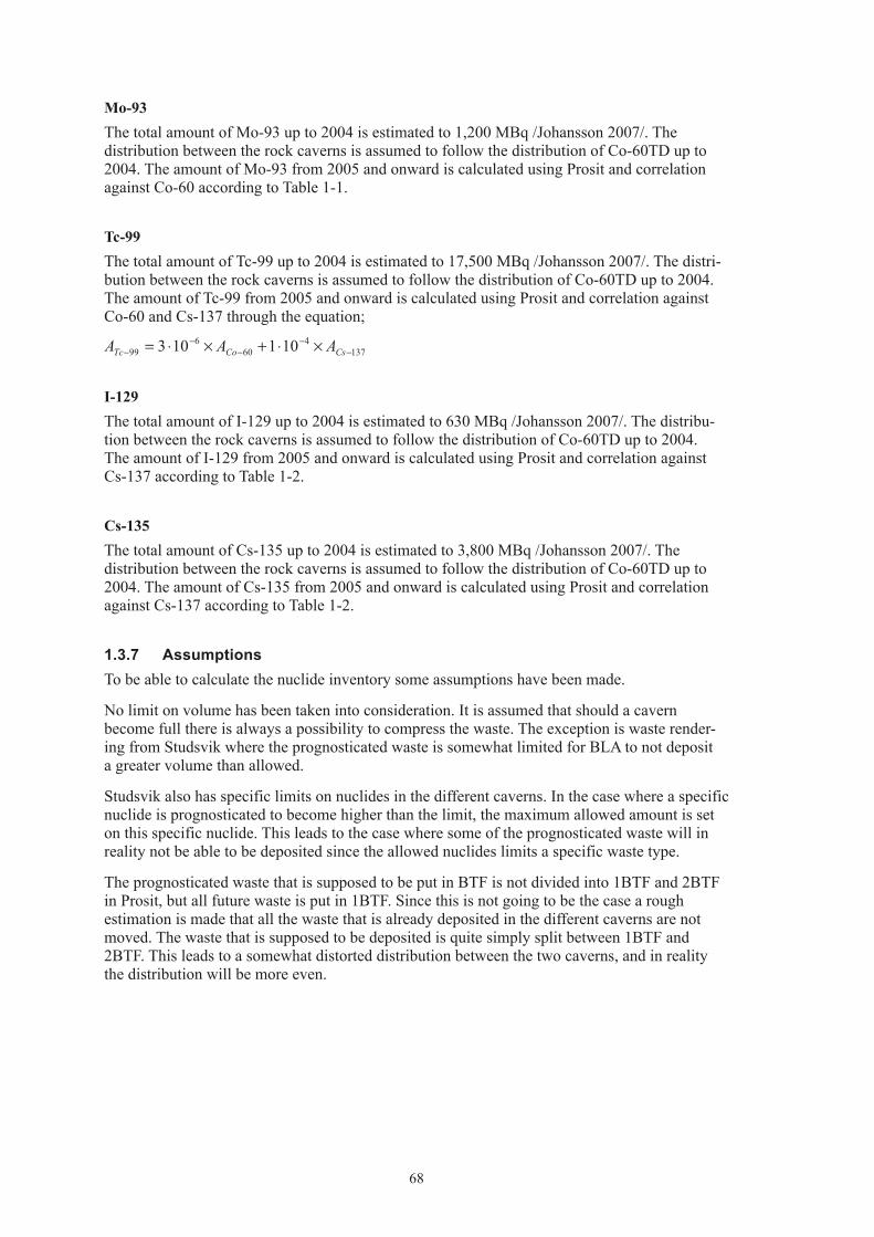
68
Mo-93The total amount of Mo-93 up to 2004 is estimated to 1,200 MBq /Johansson 2007/. The distribution between the rock caverns is assumed to follow the distribution of Co-60TD up to 2004. The amount of Mo-93 from 2005 and onward is calculated using Prosit and correlation against Co-60 according to Table 1-1.
Tc-99The total amount of Tc-99 up to 2004 is estimated to 17,500 MBq /Johansson 2007/. The distri-bution between the rock caverns is assumed to follow the distribution of Co-60TD up to 2004. The amount of Tc-99 from 2005 and onward is calculated using Prosit and correlation against Co-60 and Cs-137 through the equation;
1374
606
99 101103 −−
−−
− ×⋅+×⋅= CsCoTc AAA
I-129The total amount of I-129 up to 2004 is estimated to 630 MBq /Johansson 2007/. The distribu-tion between the rock caverns is assumed to follow the distribution of Co-60TD up to 2004. The amount of I-129 from 2005 and onward is calculated using Prosit and correlation against Cs-137 according to Table 1-2.
Cs-135The total amount of Cs-135 up to 2004 is estimated to 3,800 MBq /Johansson 2007/. The distribution between the rock caverns is assumed to follow the distribution of Co-60TD up to 2004. The amount of Cs-135 from 2005 and onward is calculated using Prosit and correlation against Cs-137 according to Table 1-2.
1.3.7 AssumptionsTo be able to calculate the nuclide inventory some assumptions have been made.
No limit on volume has been taken into consideration. It is assumed that should a cavern become full there is always a possibility to compress the waste. The exception is waste render-ing from Studsvik where the prognosticated waste is somewhat limited for BLA to not deposit a greater volume than allowed.
Studsvik also has specific limits on nuclides in the different caverns. In the case where a specific nuclide is prognosticated to become higher than the limit, the maximum allowed amount is set on this specific nuclide. This leads to the case where some of the prognosticated waste will in reality not be able to be deposited since the allowed nuclides limits a specific waste type.
The prognosticated waste that is supposed to be put in BTF is not divided into 1BTF and 2BTF in Prosit, but all future waste is put in 1BTF. Since this is not going to be the case a rough estimation is made that all the waste that is already deposited in the different caverns are not moved. The waste that is supposed to be deposited is quite simply split between 1BTF and 2BTF. This leads to a somewhat distorted distribution between the two caverns, and in reality the distribution will be more even.

69
2 Nuclide inventory – NPP life‑time 50 years
The inventory for a life-time of the nuclear power plants of 50 years has been calculated according to the methods described in Section 1.3. The result is an inventory that consists of approximately 1.5·1015 Bq at the time of closure (31 December 2040). In Table 2-1 the inventory is presented for all the nuclides.
Table 2‑1. Inventory 31 December 2040.
Nuclide Total Silo BMA 1BTF 2BTF BLA
Correlated to Co-60:Co-60 9.3E+13 8.5E+13 7.0E+12 2.9E+11 3.7E+11 3.6E+10Cl-36 1.4E+09 1.1E+09 2.3E+08 1.1E+07 3.1E+07 1.0E+06Ag-108m 1.2E+11 9.2E+10 2.0E+10 4.8E+08 2.3E+09 4.2E+08Ba-133 3.1E+09 2.8E+09 2.8E+08 1.3E+07 2.8E+07 1.7E+06Be-10 1.2E+06 9.7E+05 2.2E+05 5.1E+03 2.5E+04 8.1E+02C-14 org. 1.8E+12 1.4E+12 3.2E+11 7.4E+09 5.5E+10 1.2E+09C-14 inorg. 4.1E+12 3.2E+12 7.4E+11 1.7E+10 1.3E+11 2.7E+09C-14 tot 5.9E+12 4.6E+12 1.1E+12 2.5E+10 1.8E+11 3.9E+09Fe-55 2.1E+13 2.0E+13 1.5E+12 2.9E+10 2.9E+10 4.2E+09H-3 3.9E+10 3.5E+10 3.8E+09 1.6E+08 4.0E+08 2.2E+07Ho-166m 8.9E+09 7.0E+09 1.6E+09 5.8E+07 1.9E+08 1.7E+07Mo-93 3.7E+09 2.9E+09 6.8E+08 4.4E+07 8.9E+07 2.0E+07Nb-93m 5.5E+11 4.8E+11 5.9E+10 2.3E+09 6.6E+09 3.2E+08Nb-94 2.0E+10 1.6E+10 3.6E+09 8.5E+07 4.2E+08 1.3E+07Ni-59 9.5E+12 7.3E+12 2.1E+12 2.1E+10 4.2E+10 5.3E+09Ni-63 1.2E+15 8.9E+14 2.6E+14 2.3E+12 2.8E+12 6.6E+11Sb-125 2.3E+12 2.1E+12 1.5E+11 6.1E+09 6.2E+09 3.1E+08Zr-93 2.3E+09 1.8E+09 4.2E+08 1.5E+07 4.8E+07 4.3E+06Correlated to Cs-137:Cs-137 1.3E+14 1.1E+14 2.0E+13 6.7E+11 1.8E+12 4.8E+10Cd-113m 3.5E+10 3.1E+10 3.7E+09 1.8E+08 3.4E+08 1.1E+07Cs-134 9.6E+11 8.9E+11 7.0E+10 6.1E+08 6.1E+08 2.5E+07Cs-135 5.1E+09 4.0E+09 1.0E+09 1.6E+07 1.1E+08 2.0E+06Eu-152 5.4E+09 3.6E+09 4.0E+08 1.5E+08 1.1E+08 1.1E+09Eu-154 2.8E+12 2.5E+12 2.3E+11 1.2E+10 1.7E+10 7.5E+08Eu-155 6.0E+11 5.5E+11 4.7E+10 1.7E+09 1.8E+09 8.1E+07I-129 1.0E+09 8.1E+08 1.8E+08 3.1E+06 1.9E+07 3.1E+05Pd-107 3.2E+08 2.6E+08 5.4E+07 1.5E+06 5.9E+06 1.2E+05Pm-147 1.9E+12 1.7E+12 1.6E+11 2.1E+09 2.1E+09 1.0E+08Ru-106 1.6E+09 1.4E+09 1.2E+08 2.6E+06 2.6E+06 3.1E+03Se-79 1.3E+09 1.0E+09 2.1E+08 5.9E+06 2.4E+07 4.9E+05Sm-151 7.0E+11 5.7E+11 1.1E+11 3.4E+09 1.2E+10 2.7E+08Sn-126 1.6E+08 1.3E+08 2.7E+07 7.4E+05 2.9E+06 6.2E+04Sr-90 1.3E+13 1.1E+13 1.7E+12 6.4E+10 2.1E+11 4.7E+09Tc-99* 4.1E+11 3.6E+11 3.7E+10 7.0E+09 7.6E+09 5.0E+08

70
Nuclide Total Silo BMA 1BTF 2BTF BLA
Correlated to Pu-239 + Pu-240:Pu-239 1.1E+10 8.9E+09 2.0E+09 1.5E+08 2.0E+08 1.3E+07Pu-240 2.3E+10 1.8E+10 4.0E+09 3.0E+08 4.0E+08 2.6E+07U-232 7.5E+05 5.7E+05 1.5E+05 9.6E+03 1.1E+04 6.0E+02U-234 3.5E+07 2.6E+07 7.7E+06 5.0E+05 5.4E+05 3.0E+04U-235 4.7E+08 1.4E+07 2.8E+06 1.9E+07 7.5E+05 4.3E+08U-236 1.4E+07 1.0E+07 3.0E+06 1.9E+05 3.7E+05 9.0E+03U-238 1.5E+09 2.8E+07 6.2E+06 3.3E+05 8.8E+05 1.4E+09Np-237 1.6E+08 1.3E+08 2.5E+07 4.1E+05 1.9E+06 2.7E+04Pu-238 4.9E+10 3.8E+10 9.6E+09 3.5E+08 6.0E+08 4.7E+07Pu-241 8.2E+11 6.6E+11 1.4E+11 7.5E+09 8.6E+09 4.8E+08Pu-242 1.1E+08 7.9E+07 2.3E+07 1.5E+06 1.6E+06 9.0E+04Am-241 5.0E+11 4.9E+11 6.9E+09 8.4E+08 4.9E+08 5.0E+07Am-242m 3.0E+08 2.2E+08 6.2E+07 4.0E+06 4.4E+06 2.4E+05Am-243 1.1E+09 8.4E+08 2.3E+08 1.5E+07 1.6E+07 9.0E+05Cm-243 2.9E+08 2.3E+08 5.5E+07 3.0E+06 2.0E+06 2.3E+05Cm-244 1.0E+10 8.5E+09 1.4E+09 1.0E+08 1.1E+08 2.2E+07Cm-245 1.0E+07 7.9E+06 2.3E+06 1.5E+05 1.6E+05 9.0E+03Cm-246 2.8E+06 2.1E+06 6.1E+05 4.0E+04 4.3E+04 2.4E+03Total 1.4E+15 1.2E+15 3.0E+14 3.5E+12 5.5E+12 7.8E+11
* Tc-99 has in effect been correlated towards both Co-60 and Cs-137.

71
3 Nuclide inventory – NPP life‑time 60 years
The inventory for a life-time of the nuclear power plants of 60 years has been calculated according to the methods described in Section 1.3. The result is an inventory that consists of approximately 1.7·1015 Bq at the time of closure (31 December 2050). In Table 3-1 the inventory is presented for all the nuclides.
Table 3‑1. Inventory 31 December 2050.
Nuclide Total Silo BMA 1BTF 2BTF BLA
Correlated to Co-60:Co-60 9.3E+13 8.5E+13 6.8E+12 2.9E+11 3.1E+11 3.1E+10Cl-36 1.6E+09 1.3E+09 2.5E+08 1.2E+07 3.2E+07 1.2E+06Ag-108m 1.4E+11 1.1E+11 2.1E+10 6.0E+08 2.4E+09 4.2E+08Ba-133 3.2E+09 2.9E+09 2.6E+08 1.3E+07 2.1E+07 1.5E+06Be-10 1.4E+06 1.2E+06 2.3E+05 6.4E+03 2.6E+04 9.2E+02C-14 org. 2.1E+12 1.7E+12 3.4E+11 9.5E+09 5.8E+10 1.4E+09C-14 inorg. 5.0E+12 4.0E+12 8.0E+11 2.2E+10 1.3E+11 3.3E+09C-14 tot 7.1E+12 5.8E+12 1.1E+12 3.2E+10 1.9E+11 4.7E+09Fe-55 2.1E+13 2.0E+13 1.5E+12 2.9E+10 2.9E+10 4.0E+09H-3 4.0E+10 3.6E+10 3.4E+09 1.7E+08 3.0E+08 1.9E+07Ho-166m 1.0E+10 8.4E+09 1.8E+09 7.1E+07 2.0E+08 2.0E+07Mo-93 4.2E+09 3.2E+09 7.5E+08 5.2E+07 9.7E+07 2.7E+07Nb-93m 5.7E+11 5.0E+11 5.3E+10 2.5E+09 5.3E+09 3.0E+08Nb-94 2.4E+10 2.0E+10 3.9E+09 1.1E+08 4.4E+08 1.5E+07Ni-59 1.1E+13 9.0E+12 2.1E+12 2.3E+10 4.4E+10 6.1E+09Ni-63 1.4E+15 1.1E+15 2.6E+14 2.4E+12 2.8E+12 7.7E+11Sb-125 2.3E+12 2.1E+12 1.5E+11 6.1E+09 6.1E+09 2.9E+08Zr-93 2.7E+09 2.2E+09 4.5E+08 1.8E+07 5.1E+07 5.1E+06Correlated to Cs-137:Cs-137 1.4E+14 1.2E+14 1.9E+13 6.6E+11 1.6E+12 4.1E+10Cd-113m 3.5E+10 3.2E+10 3.2E+09 1.6E+08 2.6E+08 7.3E+06Cs-134 9.7E+11 8.9E+11 7.0E+10 6.1E+08 6.1E+08 1.8E+07Cs-135 5.6E+09 4.4E+09 1.1E+09 1.8E+07 1.1E+08 2.1E+06Eu-152 4.9E+09 3.7E+09 3.4E+08 1.3E+08 1.0E+08 6.5E+08Eu-154 2.7E+12 2.5E+12 2.1E+11 1.0E+10 1.2E+10 4.4E+08Eu-155 6.0E+11 5.5E+11 4.6E+10 1.4E+09 1.5E+09 4.6E+07I-129 1.1E+09 9.3E+08 1.9E+08 3.6E+06 1.9E+07 3.3E+05Pd-107 3.7E+08 3.0E+08 5.6E+07 1.7E+06 6.1E+06 1.3E+05Pm-147 1.9E+12 1.7E+12 1.6E+11 2.1E+09 2.1E+09 7.4E+07Ru-106 1.6E+09 1.4E+09 1.2E+08 2.6E+06 2.6E+06 3.1E+03Se-79 1.5E+09 1.2E+09 2.3E+08 6.7E+06 2.4E+07 5.1E+05Sm-151 7.7E+11 6.5E+11 1.1E+11 3.7E+09 1.1E+10 2.6E+08Sn-126 1.8E+08 1.5E+08 2.8E+07 8.4E+05 3.0E+06 6.3E+04Sr-90 1.3E+13 1.2E+13 1.5E+12 6.4E+10 1.8E+11 3.9E+09Tc-99* 5.2E+11 4.6E+11 4.4E+10 7.4E+09 8.1E+09 6.4E+08

72
Nuclide Total Silo BMA 1BTF 2BTF BLA
Correlated to Pu-239 + Pu-240:Pu-239 1.3E+10 1.1E+10 2.0E+09 1.6E+08 2.1E+08 1.3E+07Pu-240 2.7E+10 2.2E+10 4.1E+09 3.1E+08 4.1E+08 2.7E+07U-232 8.4E+05 6.7E+05 1.5E+05 9.6E+03 1.0E+04 5.7E+02U-234 4.1E+07 3.2E+07 8.3E+06 5.3E+05 5.7E+05 3.1E+04U-235 4.7E+08 1.7E+07 3.2E+06 1.9E+07 8.5E+05 4.3E+08U-236 1.6E+07 1.2E+07 3.2E+06 2.1E+05 3.9E+05 9.4E+03U-238 1.5E+09 3.4E+07 6.8E+06 3.9E+05 9.4E+05 1.4E+09Np-237 1.9E+08 1.6E+08 2.9E+07 4.7E+05 2.0E+06 2.8E+04Pu-238 5.5E+10 4.5E+10 9.5E+09 3.7E+08 6.0E+08 4.6E+07Pu-241 8.3E+11 6.8E+11 1.3E+11 6.4E+09 7.0E+09 3.6E+08Pu-242 1.2E+08 9.6E+07 2.5E+07 1.6E+06 1.7E+06 9.4E+04Am-241 4.9E+11 4.8E+11 7.7E+09 8.6E+08 5.1E+08 5.3E+07Am-242m 3.4E+08 2.7E+08 6.5E+07 4.1E+06 4.5E+06 2.4E+05Am-243 1.3E+09 1.0E+09 2.5E+08 1.6E+07 1.7E+07 9.3E+05Cm-243 3.1E+08 2.5E+08 5.3E+07 2.5E+06 1.8E+06 2.0E+05Cm-244 1.1E+10 9.2E+09 1.2E+09 8.3E+07 9.0E+07 1.9E+07Cm-245 1.2E+07 9.6E+06 2.5E+06 1.6E+05 1.7E+05 9.3E+03Cm-246 3.3E+06 2.5E+06 6.6E+05 4.2E+04 4.5E+04 2.5E+03Total 1.7E+15 1.4E+15 3.0E+14 3.6E+12 5.1E+12 8.8E+11
* Tc-99 has in effect been correlated towards both Co-60 and Cs-137.

73
4 Full nuclide inventory
The full nuclide inventory is calculated according to Section 1.3.5. The result is an inventory that consists of 1·1016 Bq at the time of closure at 2040 but with a theoretical continued waste production with no decay taken into account. In Table 4-1 the inventory is presented for all the nuclides. No consideration is taken to the limit in Table 1-4.
Table 4‑1. Full inventory 2040 for SFR 1 regarding activity.
Nuclide Total Silo BMA 1BTF 2BTF BLA
Correlated to Co-60:Co-60 6.5E+14 5.9E+14 4.9E+13 2.0E+12 2.6E+12 2.5E+11Cl-36 9.4E+09 7.5E+09 1.6E+09 7.3E+07 2.1E+08 7.2E+06Ag-108m 8.0E+11 6.4E+11 1.4E+11 3.4E+09 1.6E+10 2.9E+09Ba-133 2.2E+10 2.0E+10 2.0E+09 8.8E+07 1.9E+08 1.2E+07Be-10 8.4E+06 6.7E+06 1.5E+06 3.5E+04 1.7E+05 5.6E+03C-14 org. 1.2E+13 9.6E+12 2.2E+12 5.1E+10 3.8E+11 8.0E+09C-14 inorg. 2.9E+13 2.2E+13 5.2E+12 1.2E+11 9.0E+11 1.9E+10C-14 tot 4.1E+13 3.2E+13 7.4E+12 1.7E+11 1.3E+12 2.7E+10Fe-55 1.5E+14 1.4E+14 1.0E+13 2.0E+11 2.0E+11 2.9E+10H-3 2.7E+11 2.4E+11 2.6E+10 1.1E+09 2.8E+09 1.5E+08Ho-166m 6.2E+10 4.9E+10 1.1E+10 4.1E+08 1.3E+09 1.2E+08Mo-93 2.6E+10 2.0E+10 4.7E+09 3.1E+08 6.2E+08 1.4E+08Nb-93m 3.8E+12 3.3E+12 4.1E+11 1.6E+10 4.6E+10 2.2E+09Nb-94 1.4E+11 1.1E+11 2.5E+10 5.9E+08 2.9E+09 9.2E+07Ni-59 6.6E+13 5.1E+13 1.4E+13 1.4E+11 2.9E+11 3.7E+10Ni-63 8.0E+15 6.2E+15 1.8E+15 1.6E+13 1.9E+13 4.6E+12Sb-125 1.6E+13 1.5E+13 1.1E+12 4.2E+10 4.3E+10 2.1E+09Zr-93 1.6E+10 1.2E+10 2.9E+09 1.0E+08 3.3E+08 3.0E+07Correlated to Cs-137:Cs-137 9.4E+14 7.8E+14 1.4E+14 4.6E+12 1.3E+13 3.4E+11Cd-113m 2.4E+11 2.1E+11 2.5E+10 1.2E+09 2.3E+09 7.4E+07Cs-134 6.7E+12 6.2E+12 4.8E+11 4.3E+09 4.3E+09 1.7E+08Cs-135 3.6E+10 2.8E+10 7.2E+09 1.1E+08 7.6E+08 1.4E+07Eu-152 3.7E+10 2.5E+10 2.8E+09 1.1E+09 7.4E+08 7.5E+09Eu-154 1.9E+13 1.7E+13 1.6E+12 8.3E+10 1.2E+11 5.2E+09Eu-155 4.2E+12 3.8E+12 3.3E+11 1.2E+10 1.2E+10 5.6E+08I-129 7.0E+09 5.6E+09 1.3E+09 2.1E+07 1.3E+08 2.2E+06Pd-107 2.2E+09 1.8E+09 3.7E+08 1.0E+07 4.1E+07 8.6E+05Pm-147 1.3E+13 1.2E+13 1.1E+12 1.5E+10 1.5E+10 7.0E+08Ru-106 1.1E+10 1.0E+10 8.1E+08 1.8E+07 1.8E+07 2.2E+04Se-79 8.8E+09 7.1E+09 1.5E+09 4.1E+07 1.6E+08 3.4E+06Sm-151 4.9E+12 4.0E+12 7.6E+11 2.3E+10 8.2E+10 1.9E+09Sn-126 1.1E+09 8.9E+08 1.9E+08 5.2E+06 2.0E+07 4.3E+05Sr-90 8.9E+13 7.5E+13 1.2E+13 4.5E+11 1.4E+12 3.3E+10Tc-99* 2.9E+12 2.5E+12 2.6E+11 4.8E+10 5.3E+10 3.5E+09

74
Nuclide Total Silo BMA 1BTF 2BTF BLA
Correlated to Pu-239 + Pu-240:Pu-239 7.8E+10 6.2E+10 1.4E+10 1.0E+09 1.4E+09 9.1E+07Pu-240 1.6E+11 1.2E+11 2.7E+10 2.1E+09 2.8E+09 1.8E+08U-232 5.2E+06 4.0E+06 1.0E+06 6.7E+04 7.4E+04 4.1E+03U-234 2.4E+08 1.8E+08 5.3E+07 3.5E+06 3.7E+06 2.1E+05U-235 3.2E+09 9.8E+07 2.0E+07 1.3E+08 5.2E+06 3.0E+09U-236 9.7E+07 7.2E+07 2.1E+07 1.3E+06 2.6E+06 6.2E+04U-238 1.0E+10 1.9E+08 4.3E+07 2.3E+06 6.1E+06 9.9E+09Np-237 1.1E+09 9.0E+08 1.7E+08 2.8E+06 1.3E+07 1.9E+05Pu-238 3.4E+11 2.6E+11 6.7E+10 2.4E+09 4.2E+09 3.3E+08Pu-241 5.7E+12 4.6E+12 9.7E+11 5.2E+10 6.0E+10 3.4E+09Pu-242 7.3E+08 5.5E+08 1.6E+08 1.0E+07 1.1E+07 6.2E+05Am-241 3.5E+12 3.4E+12 4.8E+10 5.8E+09 3.4E+09 3.5E+08Am-242m 2.1E+09 1.6E+09 4.3E+08 2.8E+07 3.0E+07 1.7E+06Am-243 7.6E+09 5.8E+09 1.6E+09 1.0E+08 1.1E+08 6.2E+06Cm-243 2.0E+09 1.6E+09 3.8E+08 2.1E+07 1.4E+07 1.6E+06Cm-244 7.0E+10 5.9E+10 9.4E+09 7.1E+08 7.8E+08 1.5E+08Cm-245 7.3E+07 5.5E+07 1.6E+07 1.0E+06 1.1E+06 6.2E+04Cm-246 1.9E+07 1.5E+07 4.2E+06 2.7E+05 3.0E+05 1.7E+04Total 1.0E+16 7.9E+15 2.0E+15 2.4E+13 3.8E+13 5.3E+12
* Tc-99 has in effect been correlated towards both Co-60 and Cs-137.
75
5 Uncertainties
The one uncertainty that overshadows all others is the concept of correlation factors.
Large uncertainties are involved in the use of general correlation factors to estimate the activity content in specific waste types. The correlation factors evaluated for specific radionuclides vary within orders of magnitude, which gives an indication of the uncertainty interval. In addition, no statistical evaluations have been made in this study to prove that correlations between the key nuclides (Co-60, Cs-137 and Pu-239+240) and the other nuclides exist.
The outcome of the safety assessment will, however, give indications on which radionuclides are of major concern to reduce the uncertainties in the reference inventory.
Another important uncertainty is related to the estimated amount of future waste. The life-span of the reactors is unknown and thus the amount of waste.

76
6 References
Firestone et al. 1998. Table of Isotopes, Eight edition, 1998 Update, Wiely Interscience.
Johansson C, 2007. Prognos över nyttjande av SFR 1, Dok ID 1069693, version 1.0.
Lindgren M, Pers K, Skagius K, Wiborgh M, Brodén K, Carlsson J, Riggare P, Skogsberg M, 1998. Low and Intermediate Level Waste in SFL 3-5: Reference Inventory. SKB report Reg. No 19.41/DL31. SKB.
Lindgren M, Pettersson M, Wiborgh M, 2007. Correlation factors for C-14, Cl-36, Ni-59, Ni-63, Mo-93, Tc-99, I-129 and Cs-135 in operational waste for SFR 1. SKB R-07-05, Svensk Kärnbränslehantering AB.
Magnusson Å, Stenström K, 2005. 14C produced in Swedish nuclear power reactors – measurements on spent ion exchange resins, various process water systems and ejector off-gas. SKB R-05-78, Svensk Kärnbränslehantering AB.
Magnusson Å, Stenström K, Aronsson P-O, 2007. Characterization of 14C in process water systems, spent resins and off-gas of Swedish LWRs, Report 01-07.
Triumf, 2007. Database over radioactive operational waste in SFR 1. Maintained by SKB [accessed February 2007].
Prosit, 2007. Interface that extracts information from Triumf. Maintained by SKB [accessed February 2007].

77
Appendix C
Waste types in BLA
1 General 791.1 Waste in BLA 791.2 Definitions 791.3 Uncertainties – general 80
2 B.12 812.1 Waste type description 81
2.1.1 Waste package 812.1.2 Materials – chemical composition 812.1.3 Radionuclide inventory 822.1.4 Waste production 82
2.2 Reference waste type description 822.2.1 Waste package and material 822.2.2 Radionuclide inventory 83
2.3 Uncertainties 84
3 B.20 853.1 Waste type description 85
3.1.1 Waste package 853.1.2 Materials – chemical composition 853.1.3 Radionuclide inventory 863.1.4 Waste production 86
3.2 Reference waste type description 863.2.1 Waste package and material 863.2.2 Radionuclide inventory 87
3.3 Uncertainties 87
4 F.12 884.1 Waste type description 88
4.1.1 Waste package 884.1.2 Materials – chemical composition 884.1.3 Radionuclide inventory 894.1.4 Waste production 89
4.2 Reference waste type description 894.2.1 Waste package and material 894.2.2 Radionuclide inventory 90
4.3 Uncertainties 91
5 F.20 925.1 Waste type description 92
5.1.1 Waste package 925.1.2 Materials – chemical composition 925.1.3 Radionuclide inventory 935.1.4 Waste production 93
5.2 Reference waste type description 935.2.1 Waste package and material 935.2.2 Radionuclide inventory 94
5.3 Uncertainties 94

78
6 O.12 956.1 Waste type description 95
6.1.1 Waste package 956.1.2 Materials – chemical composition 956.1.3 Radionuclide inventory 966.1.4 Waste production 96
6.2 Reference waste type description 966.2.1 Waste package and material 966.2.2 Radionuclide inventory 97
6.3 Uncertainties 98
7 R.12 997.1 Waste type description 99
7.1.1 Waste package 997.1.2 Materials – chemical composition 997.1.3 Radionuclide inventory 1007.1.4 Waste production 100
7.2 Reference waste type description 1007.2.1 Waste package and material 1007.2.2 Radionuclide inventory 101
7.3 Uncertainties 102
8 S.12 1038.1 Waste type description 103
8.1.1 Waste package 1038.1.2 Materials – chemical composition 1038.1.3 Radionuclide inventory 1048.1.4 Waste production 104
8.2 Reference waste type description 1048.2.1 Waste package and material 1048.2.2 Radionuclide inventory 105
8.3 Uncertainties 106
9 S.14 1079.1 Waste type description 107
9.1.1 Waste package 1079.1.2 Materials – chemical composition 1079.1.3 Radionuclide inventory 1089.1.4 Waste production 108
9.2 Reference waste type description 1089.2.1 Waste package and material 1089.2.2 Radionuclide inventory 109
9.3 Uncertainties 112
10 O.99:3 11310.1 Waste type description 113
10.1.1 Waste package 11310.1.2 Materials – chemical composition 11310.1.3 Radionuclide inventory 11410.1.4 Waste production 114
10.2 Reference waste type description 11410.2.1 Waste package and material 11410.2.2 Radionuclide inventory 115
10.3 Uncertainties 115
11 Other waste types 116
12 References 117

79
1 General
1.1 Waste in BLAIn SFR in the BLA – rock cavern for low-level waste – short-lived waste from the nuclear power plants and the Studsvik research site are disposed off. The BLA cavern is approximately 160 m long, 15 m wide and has a height of 12.5 m. The cavern is very simple to its construction, basically there is only a concrete floor on which containers are placed. During the operational phase a ceiling has been placed over the waste in order to minimise water dripping on to the waste. This roof will be dismantled when the repository is closed.
The waste materials are metal scrap (iron/steel, aluminium); cellulose (e.g. wood, textile, paper), other organic materials (e.g. plastics, cables) and other waste like insulation (e.g. rock wool).
The dose rate allowed on the waste packages is maximum 2 mSv/h at the surface of the pack-ages. The amounts of radionuclides are low, dominating nuclide are Co-60. Other criteria for acceptance are:
• Construction,geometry,dimensionsandweightmustbesuitedtothehandlingsysteminSFR and the transportation system in general and in BLA in particular. The strength of the packages must be sufficient to withstand normal and abnormal handling.
• Eachpackagemusthaveanindividualidentityandtheradionuclidecontentofgammaemitting nuclides shall be known.
• Surfacecontaminationshouldnotexceed40kBq/m2 for gamma and beta emitting nuclides and 4 kBq/m2 for alpha emitting nuclides.
• Theinternaldoseratesandintegrateddosemustnotaffectthebarrierpropertiesintherepository.
• Thechemicalandphysicalpropertiesandthestructureofthewasteshouldbeknown.
• Chemicalaggressiveorexplosivematerial,pressurisedgasandfreeliquidarenotallowed.
• Gasproductionfromthewastemustnotbetoobig.
• Thewasteshallhaveenoughresistancetowardscorrosionthattheintegrityofthepackageis kept until sealing of the repository.
• Burnablewastemustnotbesubjecttoself-ignition.
• Complexingagentsshouldifpossiblebeavoided.
All waste is normally packed in ISO containers. Inside the ISO container the waste could also have inner packages e.g. steel drums, bales, boxes etc. Some of the waste has been compacted.
1.2 DefinitionsSurface area is defined as the area subject to anaerobic corrosion and gas production after seal-ing of the repository.

80
1.3 Uncertainties – general
• Thepresentedwastetypesdescribethetypesthathavebeen,areorcanbeforeseentobeproduced in Sweden. New waste types may be present in the future.
• Almostalldataisbasedonliteraturevalues,smallerchangesmaynotbeenproperlydocumented.
• Allfutureproductionisbasedonarelativesimpleprognosismodel.Thismodel,describedin Appendix A, was chosen since the uncertainties about processes etc are large.
• Noregardhasbeentakentoimprovementsinprocessesetc.
• Areferencepackagehasbeenchosenbasedonbestestimates.Actualpackagesmaydifferconsiderably from this reference package, the uncertainty for the whole population of pack-ages is judged to be smaller.
• BigcomponentsasheatexchangersetccouldinthefuturebeofinteresttodisposeoffinBLA. See Chapter 10 in this appendix.
• Fortheradionuclideinventoryforeachwastepackagetheamountpresentediseitherbasedon the amount received from correlation factors or actual measurements when applicable. When there is a difference between different sub types of waste packages within one waste type the inventory presented in this appendix is the most conservative one.
• Voidpresentedinthisreportisbasedonbestestimates,theestimatescanbequitecrude.
• Tc-99iscorrelatedagainstbothCo-60andCs-137whenquantifyingtheinventories,according to Appendix B. In the tables “Radionuclide composition of a reference waste package” however Tc-99 is presented as only correlated towards Cs-137.
Figure 1‑1. BLA.

81
2 B.12
2.1 Waste type description2.1.1 Waste packageThe B.12 waste type consists of a standard ISO-container containing iron/steel, aluminium, cellulose and other organic materials generated at the Barsebäck nuclear power plant. The material is classified as low level waste.
The physical properties and chemical conditions are well known. The following restrictions are always applicable:
• ThegeneralrestrictionslistedinSection1.1.
• Sincethepackagecontainsburnablesubstancestherestrictionsregardingself-ignitionetcare of special importance.
• ThecontentsoftoxicmaterialshouldfallwithinthelimitsforSFR1.Thatmeansavoidanceof toxic material. Small amounts of lead and PVC could follow this waste stream.
PackagingThe ISO container is made of steel with the length of 6.1 m, width of 2.4 m and height of 1.3 m. The container is often referred to as ’20-foot half-height container’. The weight of steel is approximately 1,900 kg and the surface area of the container is approximately 104 m2. The floor of the container could be of plywood or steel. The plywood floor weighs approximately 310 kg. The variation of weight between containers is between 1,800–2,300 kg.
Other containers are possible, 10-foot full- or half-height and 20-foot full-height could be used.
Treatment and conditioningThe raw waste is collected from controlled areas from various places in the power plant. Some coarse sorting is made at each collection point before transported to central treatment. The waste is normally packed in plastic bags or steel drums and then placed in the ISO container. A few containers include super compacted drums.
The void varies but is estimated to 7.5 m3 in a container.
2.1.2 Materials – chemical compositionThe amounts of different materials in a B.12 container are given in Table 2-1. Data comes from /Berntsson 1990/ and (Jan-Eric Jönsson, Barsebäck Kraft, 2000, pers. comm.). The mix of different waste materials has changed from time to time depending if incineration is used, on different maintenance work or other reasons.
The weight of the raw waste material is normally 10,000 kg per package including the weight of the container /Johansson 2000/. The weight on the waste material can vary from approximately 5,000–15,000 kg depending on different waste materials.

82
Table 2‑1. Amount of different material in a typical package B.12.
Material Weight (kg) Area (m2) Weight (%)*
Iron/steel 0–10,000 0–508 0–100Aluminium 0–200 0–30 0–2Cellulose (including wood, paper, textiles, absorbed water)
0–5,000 0–50
Other organic material (including plastics, rubber, cable)
0–3,500 0–35
Other material (including insulation like mineral wool etc)
0–2,500 0–25
* Upper limit calculated as per cent of the ratio between mass of material and 10,000 kg.
2.1.3 Radionuclide inventoryBefore the waste is transported from Barsebäck NPP to SFR 1 a measurement of gamma emit-ting nuclides is performed. Dominating nuclides are Co-60 and Cs-137. The amounts of these nuclides are between 0 and 5.4·109 Bq for Co-60 and between 0 and 3.2·108 Bq for Cs-137. Other nuclides than gamma emitting ones must be calculated according to Appendix B.
The dose rate limit for this package is 2 mSv/h but normally it is between 0–1.5 mSv/h on 1 m. The surface contamination should not exceed 40 kBq/m2 for gamma and beta and 4 kBq/m2 for alpha emitting nuclides. The waste packages are usually free of contamination.
2.1.4 Waste productionThe waste type was in production from 1991. No more production is foreseen, see Appendix A.
2.2 Reference waste type description2.2.1 Waste package and materialTable 2-2 shows the content of different materials and steel surface areas of the packaging in typical package from Barsebäck.
The assumed composition of the waste in a reference waste package of B.12 is given in Table 2-3. The surface area on a metal components in the waste are estimated assuming planar plates with a thickness of 5 mm, and assuming a density of 7,860 kg/m3 for carbon and stainless steel and 2,700 kg/m3 for aluminium.
The estimated volumes of the waste, the packaging materials and the void volume inside the package for a reference package are given in Table 2-5. The waste volume is estimated from the weights of the waste components in Table 2-3 and approximate densities of the different material. Average void is estimated to 50% in a package.
Void and waste volume is specified in Table 2-4.
Table 2‑2. Estimated reference packaging composition and surface area and thickness of components in an ISO container of B.12.
Component Material Weight (kg) Surface area (m2) Thickness (mm)
ISO container Carbon steel 1,900 104 1.5Plywood Cellulose 310

83
Table 2‑3. Estimated reference waste composition and surface area and thickness of components in one B.12.
Material Weight (kg) Surface area (m2) Thickness (mm)
Iron/steel 4,500 229 5Aluminium 100 15 5Cellulose (including wood, paper, textiles, absorbed water)
500 (2,000)
Other organic material (including plastics, rubber, cable)
3,000
Other material (including insulation like mineral wool etc)
400
Table 2‑4. Volumes in one waste packages of B.12.
Volume in one package (m3)
Waste 11.5Void 7.5
2.2.2 Radionuclide inventoryThe radionuclide composition of a reference waste package is calculated from the amount of Co-60 and Cs-137 in the waste according to Appendix B. The reference inventory in one pack-age at the time of production is presented in Table 2-5.
A reference waste package of the type B.12 has a surface dose rate of 2 mSv/h and no surface contamination.
Table 2‑5. Radionuclide composition of a reference waste package of the type B.12.
Nuclide Activity (Bq) Nuclide Activity (Bq)
Correlated to Co-60 Correlated to PuCo-60 9.7E+08 Pu-239 1.8E+01Cl-36 5.8E+02 Pu-240 3.5E+01Ag-108m 5.8E+04 U-232 1.6E–03Ba-133 9.7E+03 U-234 5.3E–02Be-10 5.8E-01 U-235 1.1E–03C-14 2.9E+06 U-236 2.9E–03Fe-55 9.7E+08 U-238 2.1E–02H-3 9.7E+04 Np-237 2.1E–02Ho-166m 3.9E+03 Pu-238 4.0E+01Mo-93 9.7E+02 Pu-241 5.3E+03Nb-93m 9.7E+05 Pu-242 1.6E–01Nb-94 9.7E+03 Am-241 2.1E+01Ni-59 9.7E+05 Am-242m 5.3E–01Ni-63 7.8E+07 Am-243 1.6E+00Sb-125 2.6E+07 Cm-243 1.1E+00Zr-93 9.7E+02 Cm-244 2.6E+01
Cm-245 1.6E–02

84
Nuclide Activity (Bq) Nuclide Activity (Bq)
Correlated to Cs-137 Cm-246 4.2E–03Cs-137 3.0E+07Cd-113m 1.8E+04Cs-134 2.6E+07Cs-135 3.0E+02Eu-152 2.1E+03Eu-154 3.0E+06Eu-155 2.1E+06I-129 9.1E+01Pd-107 3.0E+01Pm-147 2.7E+07Ru-106 1.5E+05Se-79 1.2E+02Sm-151 9.1E+04Sn-126 1.5E+01Sr-90 3.0E+06Tc-99 2.7E+04
2.3 Uncertainties• GeneraluncertaintiesaredescribedinSection1.3.
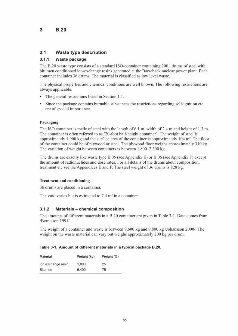
85
3 B.20
3.1 Waste type description3.1.1 Waste packageThe B.20 waste type consists of a standard ISO-container containing 200 l drums of steel with bitumen conditioned ion-exchange resins generated at the Barsebäck nuclear power plant. Each container includes 36 drums. The material is classified as low level waste.
The physical properties and chemical conditions are well known. The following restrictions are always applicable:
• ThegeneralrestrictionslistedinSection1.1.
• Sincethepackagecontainsburnablesubstancestherestrictionsregardingself-ignitionetcare of special importance.
PackagingThe ISO container is made of steel with the length of 6.1 m, width of 2.4 m and height of 1.3 m. The container is often referred to as ’20-foot half-height container’. The weight of steel is approximately 1,900 kg and the surface area of the container is approximately 104 m2. The floor of the container could be of plywood or steel. The plywood floor weighs approximately 310 kg. The variation of weight between containers is between 1,800–2,300 kg.
The drums are exactly like waste type B.05 (see Appendix E) or B.06 (see Appendix F) except the amount of radionuclides and dose rates. For all details of the drums about composition, treatment etc see the Appendices E and F. The steel weight of 36 drums is 828 kg.
Treatment and conditioning36 drums are placed in a container.
The void varies but is estimated to 7.4 m3 in a container.
3.1.2 Materials – chemical compositionThe amounts of different materials in a B.20 container are given in Table 3-1. Data comes from /Berntsson 1991/.
The weight of a container and waste is between 9,600 kg and 9,800 kg /Johansson 2000/. The weight on the waste material can vary but weighs approximately 200 kg per drum.
Table 3‑1. Amount of different materials in a typical package B.20.
Material Weight (kg) Weight (%)
Ion exchange resin 1,800 25Bitumen 5,400 75

86
3.1.3 Radionuclide inventoryBefore the waste is transported from Barsebäck NPP to SFR 1 a measurement of gamma emit-ting nuclides is performed. Dominating nuclides are Co-60 and Cs-137. The amounts of these nuclides are between 0 and 6.3·106 Bq for Co-60 and between 0 and 1.5·104 Bq for Cs-137. Other nuclides than gamma emitting ones must be calculated according to Appendix B.
The dose rate limit for this package is 2 mSv/h but normally it is between 0–0.4 mSv/h on 1 m. The surface contamination should not exceed 40 kBq/m2 for gamma and beta and 4 kBq/m2 for alpha emitting nuclides. The waste packages are usually free of contamination.
3.1.4 Waste productionThe waste type was in production until 1985. The number of packages produced was 12. No more production is foreseen, see Appendix A.
3.2 Reference waste type description3.2.1 Waste package and materialTable 3-2 shows the content of different materials and steel surface areas of the packaging in typical package from Barsebäck.
The assumed composition of the waste in a reference waste package of B.20 is given in Table 3-3.
The estimated volumes of the waste, the packaging materials and the void volume inside the package for a reference package are given in Table 3-4. The waste volume is estimated from the weights of the waste components in Table 3-3 and approximate densities of the different material. Average void is estimated to 45% in a package.
Void and waste volume is specified in Table 3-4.
Table 3‑2. Estimated reference packaging composition and surface area and thickness of components in an ISO container of B.20.
Component Material Weight (kg) Surface area (m2) Thickness (mm)
ISO container Carbon steel 1,900 104 1.5Plywood Cellulose 310Steel drums (36) Carbon steel 828 109 1.25
Table 3‑3. Estimated reference waste composition and surface area and thickness of components in one B.20.
Material Weight (kg)
Ion-exchange resin 1,800Bitumen 5,400
Table 3‑4. Volumes in one waste packages of B.20 (including drums).
Volume in one package (m3)
Waste 11.7Void 7.4

87
3.2.2 Radionuclide inventoryThe radionuclide composition of a reference waste package is calculated from the amount of Co-60 and Cs-137 in the waste according to Appendix B. The reference inventory in one pack-age at the time of production is presented in Table 3-5.
A reference waste package of the type B.20 has a surface dose rate of 2 mSv/h and no surface contamination.
Table 3‑5. Radionuclide composition of a reference waste package of the type B.20.
Nuclide Activity (Bq) Nuclide Activity (Bq)
Correlated to Co-60 Correlated to PuCo-60 2.6E+06 Pu-239 4.5E–01Cl-36 1.6E+00 Pu-240 8.9E–01Ag-108m 1.6E+02 U-232 4.0E–05Ba-133 2.6E+01 U-234 1.3E–03Be-10 1.6E-03 U-235 4.3E–02C-14 7.9E+03 U-236 3.7E–02Fe-55 2.6E+06 U-238 3.2E–02H-3 2.6E+02 Np-237 2.2E–01Ho-166m 1.1E+01 Pu-238 1.4E+00Mo-93 2.6E+00 Pu-241 1.3E+02Nb-93m 2.6E+03 Pu-242 4.0E–03Nb-94 2.6E+01 Am-241 1.0E+00Ni-59 2.6E+03 Am-242m 1.3E–02Ni-63 2.1E+05 Am-243 4.0E–02Sb-125 2.8E+04 Cm-243 2.7E–02Zr-93 2.6E+00 Cm-244 8.2E–01
Cm-245 4.0E–04Correlated to Cs-137 Cm-246 1.1E–04Cs-137 4.9E+03Cd-113m 3.0E+00Cs-134 4.9E+03Cs-135 4.9E–02Eu-152 3.5E–01Eu-154 4.9E+02Eu-155 3.5E+02I-129 1.5E–02Pd-107 4.9E–03Pm-147 4.4E+03Ru-106 2.5E+01Se-79 2.0E–02Sm-151 1.5E+01Sn-126 2.5E–03Sr-90 4.9E+02Tc-99 4.4E+00
3.3 Uncertainties• GeneraluncertaintiesaredescribedinSection1.3.

88
4 F.12
4.1 Waste type description4.1.1 Waste packageThe F.12 waste type consists of a standard ISO-container containing iron/steel, aluminium, cellulose and other organic materials generated at the Forsmark nuclear power plant. The material is classified as low level waste.
The physical properties and chemical conditions are well known. The following restrictions are always applicable:
• ThegeneralrestrictionslistedinSection1.1.
• Sincethepackagecontainsburnablesubstancestherestrictionsregardingself-ignitionetcare of special importance.
• ThecontentsoftoxicmaterialshouldfallwithinthelimitssetupearlierforSFR1.Thatmeans avoidance of toxic material. Small amounts of lead and PVC could follow this waste stream.
PackagingThe ISO container is made of steel with the length of 6.1 m, width of 2.4 m and height of 1.3 m. The container is often referred to as ’20-foot half-height container’. The weight of steel is approximately 1,900 kg and the surface area of the container is approximately 104 m2. The floor of the container could be of plywood or steel. The plywood floor weighs approximately 310 kg. The variation of weight between containers is between 1,800–2,300 kg.
Other containers are possible, 10-foot full- or half-height and 20-foot full-height could be used.
Treatment and conditioningThe raw waste is collected from controlled areas from various places in the power plant. Some coarse sorting is made at each collection point before transported to central treatment.
The waste is normally packed in plastic bags or steel drums and then placed in the ISO container. A few containers include super compacted drums with steel waste.
The void varies but is estimated to 7.5 m3 in a container.
4.1.2 Materials – chemical compositionThe amounts of different materials in a F.12 container are given in Table 4-1. Data comes from /Meijer 1987, Lindberg and Malmkvist 1992/ and (Tomas Larsson, Forsmarks Kraftgrupp AB, 2000, pers. comm.). The mix of different waste materials has changed from time to time depending if incineration is used, on different maintenance work or other reasons.
The weight of the raw waste material is normally 10,000 kg per package including the weight of the container /Johansson 2000/. The weight on the waste material can vary from approximately 5,000–15,000 kg depending on different waste materials.

89
Table 4‑1. Amount of different material in a typical package F.12.
Material Weight (kg) Area (m2) Weight (%)
Iron/steel 0–10,000 0–508 0–100Aluminium 0–200 0–30 0–2Cellulose (including wood, paper, textiles, absorbed water)
0–5,000 0–50
Other organic material (including plastics, rubber, cable)
0–3,500 0–35
Other material (including insulation like mineral wool etc)
0–2,500 0–25
* Upper limit calculated as per cent of the ratio between mass of material and 10,000 kg.
4.1.3 Radionuclide inventoryBefore the waste is transported from Forsmark NPP to SFR 1 a measurement of gamma emitting nuclides is performed. Dominating nuclides are Co-60 and Cs-137. The amounts of these nuclides are between 0 and 1.7·1010 Bq for Co-60 and between 0 and 9.1·108 Bq for Cs-137. Other nuclides than gamma emitting ones must be calculated according to Appendix B.
The dose rate limit for this package is 2 mSv/h but normally it is between 0–0.8 mSv/h on 1 m. The surface contamination should not exceed 40 kBq/m2 for gamma and beta and 4 kBq/m2 for alpha emitting nuclides. The waste packages are usually free of contamination.
4.1.4 Waste productionThe waste type has been in production since 1991 and is still in production. The annual produc-tion is estimated to 0.5, see Appendix A.
4.2 Reference waste type description4.2.1 Waste package and materialTable 4-2 shows the content of different materials and steel surface areas of the packaging in typical package from Forsmark.
The assumed composition of the waste in a reference waste package of F.12 is given in Table 4-3. The surface area on a metal components in the waste are estimated assuming planar plates with a thickness of 5 mm, and assuming a density of 7,860 kg/m3 for carbon and stainless steel and 2,700 kg/m3 for aluminium.
The estimated volumes of the waste, the packaging materials and the void volume inside the package for a reference package are given in Table 4-4. The waste volume is estimated from the weights of the waste components in Table 4-3 and approximate densities of the different material. Average void is estimated to 50% in a package.
Void and waste volume is specified in Table 4-4.
Table 4‑2. Estimated reference packaging composition and surface area and thickness of components in an ISO container of F.12.
Component Material Weight (kg) Surface area (m2) Thickness (mm)
ISO container Carbon steel 1,900 104 1.5Plywood Cellulose 310

90
Table 4‑3. Estimated reference waste composition and surface area and thickness of components in one F.12.
Material Weight (kg) Surface area (m2) Thickness (mm)
Iron/steel 4,500 229 5Aluminium 100 15 5Cellulose (including wood, paper, textiles, absorbed water)
500 (2,000)
Other organic material (including plastics, rubber, cable)
3,000
Other material (including insulation like mineral wool etc)
400
Table 4‑4. Volumes in one reference waste packages of F.12.
Volume in one package (m3)
Waste 11.5Void 7.5
4.2.2 Radionuclide inventoryThe radionuclide composition of a reference waste package is calculated from the amount of Co-60 and Cs-137 in the waste according to Appendix B. The reference inventory in one pack-age at the time of production is presented in Table 4-5.
A reference waste package of the type F.12 has a surface dose rate of 2 mSv/h and no surface contamination.
Table 4‑5. Radionuclide composition of a reference waste package of the type F.12.
Nuclide Activity (Bq) Nuclide Activity (Bq)
Correlated to Co-60 Correlated to PuCo-60 7.3E+09 Pu-239 2.0E+03Cl-36 4.4E+03 Pu-240 4.0E+03Ag-108m 4.4E+05 U-232 1.8E–01Ba-133 7.3E+04 U-234 6.0E+00Be-10 4.4E+00 U-235 4.1E+01C-14 2.2E+07 U-236 1.8E+00Fe-55 7.3E+09 U-238 3.1E+01H-3 7.3E+05 Np-237 2.0E+02Ho-166m 2.9E+04 Pu-238 9.3E+03Mo-93 7.3E+03 Pu-241 6.0E+05Nb-93m 7.3E+06 Pu-242 1.8E+01Nb-94 7.3E+04 Am-241 2.7E+03Ni-59 7.3E+06 Am-242m 6.0E+01Ni-63 5.8E+08 Am-243 1.8E+02Sb-125 5.7E+08 Cm-243 2.7E–02Zr-93 7.3E+03 Cm-244 3.5E+03
Cm-245 1.8E+00

91
Nuclide Activity (Bq) Nuclide Activity (Bq)
Correlated to Cs-137 Cm-246 4.8E–01Cs-137 1.8E+08Cd-113m 1.1E+05Cs-134 1.2E+08Cs-135 1.8E+03Eu-152 1.3E+04Eu-154 1.8E+07Eu-155 1.3E+07I-129 5.4E+02Pd-107 1.8E+02Pm-147 1.6E+08Ru-106 9.0E+05Se-79 7.2E+02Sm-151 5.4E+05Sn-126 9.0E+01Sr-90 1.8E+07Tc-99 1.6E+05
4.3 Uncertainties• GeneraluncertaintiesaredescribedinSection1.3.

92
5 F.20
5.1 Waste type description5.1.1 Waste packageThe F.20 waste type consists of a standard ISO-container containing 200 l drums of steel with bitumen conditioned ion-exchange resins generated at the Forsmark nuclear power plant. Each container includes 36 drums. The material is classified as low level waste.
The physical properties and chemical conditions are well known. The following restrictions are always applicable:
• ThegeneralrestrictionslistedinSection1.1.
• Sincethepackagecontainsburnablesubstancestherestrictionsregardingself-ignitionetcare of special importance.
PackagingThe ISO container is made of steel with the length of 6.1 m, width of 2.4 m and height of 1.3 m. The container is often referred to as ’20-foot half-height container’. The weight of steel is approximately 1,900 kg and the surface area of the container is approximately 104 m2. The floor of the container could be of plywood or steel. The plywood floor weighs approximately 310 kg. The variation of weight between containers is between 1,800–2,300 kg.
The drums are exactly like waste type F.05 (see Appendix E) except the amount of radionuclides and the dose rates. For all details of the drums about composition, treatment etc see the Appendix E. The steel weight of 36 drums is 900 kg.
Treatment and conditioning36 drums are placed in a container.
The void varies but is estimated to 7 m3 in a container.
5.1.2 Materials – chemical compositionThe amounts of different materials in a F.20 container are given in Table 5-1. Data comes from /Lindberg and Malmkvist 1991/.
The weight of a container and waste is between 6,600 kg and 7,200 kg /Johansson 2000/. The weight on the waste material can vary but weighs approximately 200 kg per drum.
Table 5‑1. Amount of different materials in a typical package F.20.
Material Weight (kg) Weight (%)
Ion exchange resin 4,680 60Bitumen 3,420 40

93
5.1.3 Radionuclide inventoryBefore the waste is transported from Forsmark NPP to SFR 1 a measurement of gamma emitting nuclides is performed. Dominating nuclides are Co-60 and Cs-137. The amounts of these nuclides are between 0 and 8.4·109 Bq for Co-60 and between 0 and 4.2·108 Bq for Cs-137. Other nuclides than gamma emitting ones must be calculated according to Appendix B.
The dose rate limit for this package is 2 mSv/h but normally it is between 0–0.1 mSv/h on 1 m. The surface contamination should not exceed 40 kBq/m2 for gamma and beta and 4 kBq/m2 for alpha emitting nuclides. The waste packages are usually free of contamination.
5.1.4 Waste productionThe waste type was in production until 1982. The number of packages produced was 15. No more production is foreseen, see Appendix A.
5.2 Reference waste type description5.2.1 Waste package and materialTable 5-2 shows the content of different materials and steel surface areas of the packaging in typical package from Forsmark.
The assumed composition of the waste in a reference waste package of F.20 is given in Table 5-3.
The estimated volumes of the waste, the packaging materials and the void volume inside the package for a reference package are given in Table 5-4. The waste volume is estimated from the weights of the waste components in Table 5-3 and approximate densities of the different material. Average void is estimated to 45% in a package.
Void and waste volume is specified in Table 5-4.
Table 5‑2. Estimated reference packaging composition and surface area and thickness of components in an ISO container of F.20.
Component Material Weight (kg) Surface area (m2) Thickness (mm)
ISO container Carbon steel 1,900 104 1.5Plywood Cellulose 310Steel drums (36) Carbon steel 900 90 1.25
Table 5‑3. Estimated reference waste composition and surface area and thickness of components in one F.20.
Material Weight (kg)
Ion-exchange resin 4,680Bitumen 3,450
Table 5‑4. Volumes in one reference waste packages of F.20 (including drums).
Volume in one package (m3)
Waste 12Void 7

94
5.2.2 Radionuclide inventoryThe radionuclide composition of a reference waste package is calculated from the amount of Co-60 and Cs-137 in the waste according to Appendix B. The reference inventory in one pack-age at the time of production is presented in Table 5-5.
A reference waste package of the type F.20 has a surface dose rate of 2 mSv/h and no surface contamination.
Table 5‑5. Radionuclide composition of a reference waste package of the type F.20.
Nuclide Activity (Bq) Nuclide Activity (Bq)
Correlated to Co-60 Correlated to PuCo-60 2.8E+09 Pu-239 4.5E+03Cl-36 1.7E+03 Pu-240 9.1E+03Ag-108m 1.7E+05 U-232 4.1E–01Ba-133 2.8E+04 U-234 1.4E+01Be-10 1.7E+00 U-235 5.3E+01C-14 8.2E+06 U-236 4.1E+00Fe-55 2.8E+09 U-238 5.8E+01H-3 2.8E+05 Np-237 4.8E+02Ho-166m 1.1E+04 Pu-238 2.6E+04Mo-93 2.8E+03 Pu-241 1.4E+06Nb-93m 2.8E+06 Pu-242 4.1E+01Nb-94 2.8E+04 Am-241 7.4E+03Ni-59 2.8E+06 Am-242m 1.4E+02Ni-63 2.2E+08 Am-243 4.1E+02Sb-125 2.3E+08 Cm-243 1.4E+02Zr-93 2.8E+03 Cm-244 2.5E+04
Cm-245 4.1E+00Correlated to Cs-137 Cm-246 1.1E+00Cs-137 1.1E+08Cd-113m 6.7E+04Cs-134 3.2E+07Cs-135 1.1E+03Eu-152 7.8E+03Eu-154 1.1E+07Eu-155 7.8E+06I-129 3.4E+02Pd-107 1.1E+02Pm-147 1.0E+08Ru-106 5.6E+05Se-79 4.5E+02Sm-151 3.4E+05Sn-126 5.6E+01Sr-90 1.1E+07Tc-99 1.0E+05
5.3 Uncertainties• GeneraluncertaintiesaredescribedinSection1.3.

95
6 O.12
6.1 Waste type description6.1.1 Waste packageThe O.12 waste type consists of a standard ISO-container containing iron/steel, aluminium, cellulose and other organic materials generated at the Oskarshamn nuclear power plant. The material is classified as low level waste.
The physical properties and chemical conditions are well known. The following restrictions are always applicable:
• ThegeneralrestrictionslistedinSection1.1.
• Sincethepackagecontainsburnablesubstancestherestrictionsregardingself-ignitionetcare of special importance.
• ThecontentsoftoxicmaterialshouldfallwithinthelimitssetupearlierforSFR1.Thatmeans avoidance of toxic material. Small amounts of lead and PVC could follow this waste stream.
PackagingThe ISO container is made of steel with the length of 6.1 m, width of 2.4 m and height of 1.3 m. The container is often referred to as ’20-foot half-height container’. The weight of steel is approximately 1,900 kg and the surface area of the container is approximately 104 m2. The floor of the container could be of plywood or steel. The plywood floor weighs approximately 310 kg. The variation of weight between containers is between 1,800–2,300 kg.
Other containers are possible, 10-foot full- or half-height and 20-foot full-height could be used.
Treatment and conditioningThe raw waste is collected from controlled areas from various places in the power plant. Some coarse sorting is made at each collection point before transported to central treatment.
The waste is normally packed in plastic bags or steel drums and then placed in the ISO container. A few containers include super compacted drums with steel waste.
The void varies but is estimated to 7.5 m3 in a container.
6.1.2 Materials – chemical compositionThe amounts of different materials in an O.12 container are given in Table 6-1. Data comes from /Meijer 1987, Ingemansson 1999/ and (Karl-Erik Ingemansson, Oskarshamns Kraftgrupp, 2000, pers. comm.). The mix of different waste materials has changed from time to time depending if incineration is used, on different maintenance work or other reasons.
The weight of the raw waste material is normally 10,000 kg per package including the weight of the container /Johansson 2000/. The weight on the waste material can vary from approximately 5,000–15,000 kg depending on different waste materials.

96
Table 6‑1. Amount of different material in a typical package O.12.
Material Weight (kg) Area (m2) Weight (%)
Iron/steel 0–10,000 0–508 0–100Aluminium 0–200 0–30 0–2Cellulose (including wood, paper, textiles, absorbed water)
0–5,000 0–50
Other organic material (including plastics, rubber, cable)
0–3,500 0–35
Other material (including insulation like mineral wool etc)
0–2,500 0–25
* Upper limit calculated as per cent of the ratio between mass of material and 10,000 kg.
6.1.3 Radionuclide inventoryBefore the waste is transported from Oskarshamn NPP to SFR 1 a measurement of gamma emitting nuclides is performed. Dominating nuclides are Co-60 and Cs-137. The amounts of these nuclides are between 0 and 6.2·1010 Bq for Co-60 and between 0 and 5.1·1011 Bq for Cs-137 (based on types B.12, F.12 and R.12). Other nuclides than gamma emitting ones must be calculated according to Appendix B.
The dose rate limit for this package is 2 mSv/h. No information is available on normal dose rates, but probably the dose rates are like the normal dose rates for types B.12, F.12 and R.12. The surface contamination should not exceed 40 kBq/m2 for gamma and beta and 4 kBq/m2 for alpha emitting nuclides. The waste packages are usually free of contamination.
6.1.4 Waste productionThe annual production is estimated to 1, see Appendix A.
6.2 Reference waste type description6.2.1 Waste package and materialTable 6-2 shows the content of different materials and steel surface areas of the packaging in typical package from Oskarshamn.
The assumed composition of the waste in a reference waste package of O.12 is given in Table 6-3. The surface area on a metal components in the waste are estimated assuming planar plates with a thickness of 5 mm, and assuming a density of 7,860 kg/m3 for carbon and stainless steel and 2,700 kg/m3 for aluminium.
The estimated volumes of the waste, the packaging materials and the void volume inside the package for a reference package are given in Table 6-4. The waste volume is estimated from the weights of the waste components in Table 6-3 and approximate densities of the different material. Average void is estimated to 50% in a package.
Void and waste volume is specified in Table 6-4.
Table 6‑2. Estimated reference packaging composition and surface area and thickness of components in a ISO container of O.12.
Component Material Weight (kg) Surface area (m2) Thickness (mm)
ISO container Carbon steel 1,900 104 1.5Plywood Cellulose 310

97
Table 6‑3. Estimated reference waste composition and surface area and thickness of components in one O.12.
Material Weight (kg) Surface area (m2) Thickness (mm)
Iron/steel 4,500 229 5Aluminium 100 15 5Cellulose (including wood, paper, textiles, absorbed water)
500 (2,000)
Other organic material (including plastics, rubber, cable)
3,000
Other material (including insulation like mineral wool etc)
400
Table 6‑4. Volumes in one waste packages of O.12.
Volume in one package (m3)
Waste 11.5Void 7.5
6.2.2 Radionuclide inventoryThe radionuclide composition of a reference waste package is calculated from the amount of Co-60 and Cs-137 in the waste according to Appendix B. The reference inventory in one pack-age at the time of production is presented in Table 6-5.
A reference waste package of the type O.12 has a surface dose rate of 2 mSv/h and no surface contamination.
Table 6‑5. Radionuclide composition of a reference waste package of the type O.12.
Nuclide Activity (Bq) Nuclide Activity (Bq)
Correlated to Co-60 Correlated to PuCo-60 7.0E+09 Pu-239 5.1E+03Cl-36 8.1E+02 Pu-240 1.0E+04Ag-108m 4.2E+05 U-232 2.3E–01Ba-133 7.0E+04 U-234 7.7E+00Be-10 4.2E+00 U-235 1.5E–01C-14 7.0E+06 U-236 2.3E+00Fe-55 7.0E+09 U-238 3.1E+00H-3 7.0E+05 Np-237 3.1E+00Ho-166m 2.8E+05 Pu-238 3.1E+04Mo-93 3.5E+05 Pu-241 7.7E+05Nb-93m 7.0E+06 Pu-242 2.3E+01Nb-94 7.0E+04 Am-241 7.7E+03Ni-59 7.0E+06 Am-242m 7.7E+01Ni-63 1.4E+09 Am-243 2.3E+02Sb-125 7.0E+08 Cm-243 1.5E+02Zr-93 7.0E+04 Cm-244 2.3E+04
Cm-245 2.3E+00

98
Nuclide Activity (Bq) Nuclide Activity (Bq)
Correlated to Cs-137 Cm-246 6.2E–01Cs-137 8.1E+07Cd-113m 4.9E+03Cs-134 8.1E+07Cs-135 4.1E+02Eu-152 5.7E+03Eu-154 8.1E+06Eu-155 5.7E+06I-129 2.4E+01Pd-107 8.1E+01Pm-147 7.3E+07Ru-106 4.1E+05Se-79 3.2E+02Sm-151 2.4E+05Sn-126 4.1E+01Sr-90 8.1E+06Tc-99 4.1E+05
6.3 Uncertainties• GeneraluncertaintiesaredescribedinSection1.3.

99
7 R.12
7.1 Waste type description7.1.1 Waste packageThe R.12 waste type consists of a standard ISO-container containing iron/steel, aluminium, cellulose and other organic materials generated at the Ringhals nuclear power plant. The material is classified as low level waste.
The physical properties and chemical conditions are well known. The following restrictions are always applicable:
• ThegeneralrestrictionslistedinSection1.1.
• Sincethepackagecontainsburnablesubstancestherestrictionsregardingself-ignitionetcare of special importance.
• ThecontentsoftoxicmaterialshouldfallwithinthelimitssetupearlierforSFR1.Thatmeans avoidance of toxic material. Small amounts of lead and PVC could follow this waste stream.
PackagingThe ISO container is made of steel with the length of 6.1 m, width of 2.4 m and height of 1.3 m. The container is often referred to as ’20-foot half-height container’. The weight of steel is approximately 1,900 kg and the surface area of the container is approximately 104 m2. The floor of the container could be of plywood or steel. The plywood floor weighs approximately 310 kg. The variation of weight between containers is between 1,800–2,300 kg.
Other containers are possible, 10-foot full- or half-height and 20-foot full-height could be used.
Treatment and conditioningThe raw waste is collected from controlled areas from various places in the power plant. Some coarse sorting is made at each collection point before transported to central treatment.
The waste is normally packed in plastic bags or steel drums and then placed in the ISO container. A few containers include super compacted drums with steel waste.
The void varies but is estimated to 7.5 m3 in a container.
7.1.2 Materials – chemical compositionThe amounts of different materials in a R.12 container are given in Table 7-1. Data comes from /Meijer 1987, Ahlqvist 1990/ and (Tommy Hansson, Ringhals AB, 2000, pers. comm.). The mix of different waste materials has changed from time to time depending if incineration is used, on different maintenance work or other reasons.
The weight of the raw waste material is normally 10,000 kg per package including the weight of the container /Johansson 2000/. The weight on the waste material can vary from approximately 5,000–15,000 kg depending on different waste materials.

100
Table 7‑1. Amount of different material in a typical package R.12.
Material Weight (kg) Area (m2) Weight (%)
Iron/steel 0–10,000 0–508 0–100Aluminium 0–200 0–30 0–2Cellulose (including wood, paper, textiles, absorbed water)
0–5,000 0–50
Other organic material (including plastics, rubber, cable)
0–3,500 0–35
Other material (including insulation like mineral wool etc)
0–2,500 0–25
* Upper limit calculated as per cent of the ratio between mass of material and 10,000 kg.
7.1.3 Radionuclide inventoryBefore the waste is transported from Ringhals NPP to SFR 1 a measurement of gamma emitting nuclides is performed. Dominating nuclides are Co-60 and Cs-137. The amounts of these nuclides are between 0 and 6.2·1011 Bq for Co-60 and between 0 and 5.1·1010 Bq for Cs-137. Other nuclides than gamma emitting ones must be calculated according to Appendix B.
The dose rate limit for this package is 2 mSv/h but normally it is between 0–1.5 mSv/h on 1 metre. The surface contamination should not exceed 40 kBq/m2 for gamma and beta and 4 kBq/m2 for alpha emitting nuclides. The waste packages are usually free of contamination.
7.1.4 Waste productionThe waste type has been in production since 1991 and is still in production. The annual produc-tion is estimated to 3, see Appendix A.
7.2 Reference waste type description7.2.1 Waste package and materialTable 7-2 shows the content of different materials and steel surface areas of the packaging in typical package from Ringhals.
The assumed composition of the waste in a reference waste package of R.12 is given in Table 7-3. The surface area on a component in the waste is estimated assuming planar plates with a thickness of 5 mm, and assuming a density of 7,860 kg/m3 for carbon and stainless steel and 2,700 kg/m3 for aluminium.
The estimated volumes of the waste, the packaging materials and the void volume inside the package for a reference package are given in Table 7-4. The waste volume is estimated from the weights of the waste components in Table 7-3 and approximate densities of the different material. Average void is estimated to 50% in a package.
Void and waste volume is specified in Table 7-4.
Table 7‑2. Estimated reference packaging composition and surface area and thickness of components in a ISO container of R.12.
Component Material Weight (kg) Surface area (m2) Thickness (mm)
ISO container Carbon steel 1,900 104 1.5Plywood Cellulose 310

101
Table 7‑3. Estimated reference waste composition and surface area and thickness of components in one R.12.
Material Weight (kg) Surface area (m2) Thickness (mm)
Iron/steel 4,500 229 5Aluminium 100 15 5Cellulose (including wood, paper, textiles, absorbed water)
500 (2,000)
Other organic material (including plastics, rubber, cable)
3,000
Other material (including insulation like mineral wool etc)
400
Table 7‑4. Volumes in one waste packages of R.12.
Volume in one package (m3)
Waste 11.5Void 7.5
7.2.2 Radionuclide inventoryThe radionuclide composition of a reference waste package is calculated from the amount of Co-60 and Cs-137 in the waste according to Appendix B. The reference inventory in one pack-age at the time of production is presented in Table 7-5.
A reference waste package of the type R.12 has a surface dose rate of 2 mSv/h and no surface contamination.
Table 7‑5. Radionuclide composition of a reference waste package of the type R.12.
Nuclide Activity (Bq) Nuclide Activity (Bq)
Correlated to Co-60 Correlated to PuCo-60 2.5E+09 Pu-239 1.5E+04Cl-36 1.5E+03 Pu-240 2.9E+04Ag-108m 1.5E+05 U-232 1.3E+00Ba-133 2.5E+04 U-234 4.4E+01Be-10 1.5E+00 U-235 8.7E–01C-14 7.4E+06 U-236 1.3E+01Fe-55 2.5E+09 U-238 1.8E+01H-3 2.5E+05 Np-237 1.8E+01Ho-166m 9.8E+03 Pu-238 1.2E+05Mo-93 2.5E+03 Pu-241 4.4E+06Nb-93m 2.5E+06 Pu-242 1.3E+02Nb-94 2.5E+04 Am-241 1.2E+05Ni-59 2.5E+06 Am-242m 4.4E+02Ni-63 2.0E+08 Am-243 1.3E+03Sb-125 1.2E+08 Cm-243 8.7E+02Zr-93 2.5E+03 Cm-244 2.9E+05
Cm-245 1.3E+01

102
Nuclide Activity (Bq) Nuclide Activity (Bq)
Correlated to Cs-137 Cm-246 3.5E+00Cs-137 3.6E+07Cd-113m 2.1E+04Cs-134 2.6E+07Cs-135 3.6E+02Eu-152 2.5E+03Eu-154 3.6E+06Eu-155 2.5E+06I-129 1.1E+02Pd-107 3.6E+01Pm-147 3.2E+07Ru-106 7.4E+05Se-79 1.4E+02Sm-151 1.1E+05Sn-126 1.8E+01Sr-90 4.3E+06Tc-99 3.2E+04
7.3 Uncertainties• GeneraluncertaintiesaredescribedinSection1.3.

103
8 S.12
8.1 Waste type description8.1.1 Waste packageThe S.12 waste type consists of a standard ISO-container containing iron/steel, aluminium, cellulose and other organic materials generated at the Studsvik Research site. The material is classified as low level waste.
The physical properties and chemical conditions are well known. The following restrictions are always applicable:
• ThegeneralrestrictionslistedinSection1.1.
• Sincethepackagecontainsburnablesubstancestherestrictionsregardingself-ignitionetcare of special importance.
• ThecontentsoftoxicmaterialshouldfallwithinthelimitssetupearlierforSFR1.Thatmeans avoidance of toxic material. Small amounts of lead and PVC could follow this waste stream.
PackagingThe ISO container is made of steel with the length of 6.1 m, width of 2.4 m and height of 1.3 m. The container is often referred to as ’20-foot half-height container’. The weight of steel is approximately 1,900 kg and the surface area of the container is approximately 104 m2. The floor of the container could be of plywood or steel. The plywood floor weighs approximately 310 kg. The variation of weight between containers is between 1,800–2,300 kg.
Other containers are possible, 10-foot full- or half-height and 20-foot full-height could be used.
Treatment and conditioningThe raw waste is collected from controlled areas from various places on the site. Some coarse sorting is made at each collection point before transported to central treatment.
The waste is normally packed in plastic bags or steel drums and then placed in the ISO container. A few containers include super compacted drums with steel waste.
The void varies but is estimated to 7.5 m3 in a container.
8.1.2 Materials – chemical compositionThe amounts of different materials in a S.12 container are given in Table 8-1. Data comes from /Meijer 1987, Öberg 1990/ and (Jan Chyssler, Studsvik RadWaste, 2000, pers. comm.). The mix of different waste materials has changed from time to time depending if incineration is used, on different maintenance work or other reasons.
The weight of the raw waste material is normally 10,000 kg per package including the weight of the container /Johansson 2000/. The weight on the waste material can vary from approximately 5,000–15,000 kg depending on different waste materials.

104
Table 8‑1. Amount of different material in a typical package S.12.
Material Weight (kg) Area (m2) Weight (%)
Iron/steel 0–10,000 0–508 0–100Aluminium 0–200 0–30 0–2Cellulose (including wood, paper, textiles, absorbed water)
0–5,000 0–50
Other organic material (including plastics, rubber, cable)
0–3,500 0–35
Other material (including insulation like mineral wool etc)
0–2,500 0–25
* Upper limit calculated as per cent of the ratio between mass of material and 10,000 kg.
8.1.3 Radionuclide inventoryBefore the waste is transported from Studsvik to SFR 1 a measurement of gamma emitting nuclides is performed. Dominating nuclides are Co-60 and Cs-137. The amounts of these nuclides are between 0 and 6.2·1010 Bq for Co-60 and between 0 and 5.1·1011 Bq for Cs-137 (based on types B.12, F.12 and R.12). Other nuclides than gamma emitting ones must be calculated according to Appendix B.
The dose rate limit for this package is 2 mSv/h. No information is available on normal dose rates, but probably the dose rates are like the normal dose rates for types B.12, F.12 and R.12. The surface contamination should not exceed 40 kBq/m2 for gamma and beta and 4 kBq/m2 for alpha emitting nuclides. The waste packages are usually free of contamination.
8.1.4 Waste productionThe waste type is not yet licensed to be deposited in SFR 1. The annual production is estimated to 1, see Appendix A.
8.2 Reference waste type description8.2.1 Waste package and materialTable 8-2 shows the content of different materials and steel surface areas of the packaging in typical package from Studsvik.
The assumed composition of the waste in a reference waste package of S.12 is given in Table 8-3. The surface area on a components in the waste are estimated assuming planar plates with a thickness of 5 mm, and assuming a density of 7,860 kg/m3 for carbon and stainless steel and 2,700 kg/m3 for aluminium.
The estimated volumes of the waste, the packaging materials and the void volume inside the package for a reference package are given in Table 8-4. The waste volume is estimated from the weights of the waste components in Table 8-3 and approximate densities of the different material. Average void is estimated to 50% in a package.
Void and waste volume is specified in Table 8-4.
Table 8‑2. Estimated reference packaging composition and surface area and thickness of components in an ISO container of S.12.
Component Material Weight (kg) Surface area (m2) Thickness (mm)
ISO container Carbon steel 1,900 104 1.5

105
Table 8‑3. Estimated reference waste composition and surface area and thickness of components in one S.12.
Material Weight (kg) Surface area (m2) Thickness (mm)
Iron/steel 4,500 229 5Aluminium 100 15 5Cellulose (including wood, paper, textiles, absorbed water)
500 (2,000)
Other organic material (including plastics, rubber, cable)
3,000
Other material (including insulation like mineral wool etc)
400
Table 8‑4. Volumes in one waste packages of S.12.
Volume in one package (m3)
Waste 11.5Void 7.5
8.2.2 Radionuclide inventoryThe radionuclide composition of a reference waste package is calculated from the amount of Co-60 and Cs-137 in the waste according to Appendix B. The reference inventory in one pack-age at the time of production is presented in Table 8-5.
A reference waste package of the type S.12 has a surface dose rate of 2 mSv/h and no surface contamination.
Table 8‑5. Radionuclide composition of a reference waste package of the type S.12.
Nuclide Activity (Bq) Nuclide Activity (Bq)
Correlated to Co-60 Correlated to PuCo-60 4.3E+09 Pu-239 1.3E+05Cl-36 8.1E+03 Pu-240 2.7E+05Ag-108m 2.6E+05 U-232 6.0E+00Ba-133 4.3E+04 U-234 2.0E+02Be-10 2.6E+00 U-235 4.0E+00C-14 4.3E+06 U-236 6.0E+01Fe-55 4.3E+09 U-238 8.0E+01H-3 4.3E+05 Np-237 8.0E+01Ho-166m 1.7E+05 Pu-238 8.0E+05Mo-93 2.2E+05 Pu-241 2.0E+07Nb-93m 4.3E+06 Pu-242 6.0E+02Nb-94 4.3E+04 Am-241 2.0E+05Ni-59 4.3E+06 Am-242m 2.0E+03Ni-63 8.6E+08 Am-243 6.0E+03Sb-125 4.3E+08 Cm-243 4.0E+03Zr-93 4.3E+04 Cm-244 6.0E+05
Cm-245 6.0E+01
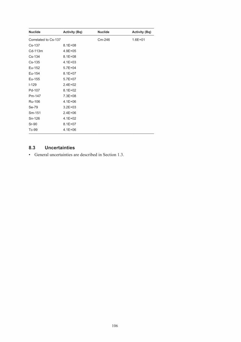
106
Nuclide Activity (Bq) Nuclide Activity (Bq)
Correlated to Cs-137 Cm-246 1.6E+01Cs-137 8.1E+08Cd-113m 4.9E+05Cs-134 8.1E+08Cs-135 4.1E+03Eu-152 5.7E+04Eu-154 8.1E+07Eu-155 5.7E+07I-129 2.4E+02Pd-107 8.1E+02Pm-147 7.3E+08Ru-106 4.1E+06Se-79 3.2E+03Sm-151 2.4E+06Sn-126 4.1E+02Sr-90 8.1E+07Tc-99 4.1E+06
8.3 Uncertainties• GeneraluncertaintiesaredescribedinSection1.3.

107
9 S.14
9.1 Waste type description9.1.1 Waste packageThe S.14 waste type consists of a standard ISO-container containing 200 l drums of steel with scrap metal and refuse generated at the Studsvik research site. The waste type is nearly identical to S.21 except that S.21 has somewhat different radionuclide content and dose rates. The description of S.21 is assumed to be covered in this description, although S.21 is placed in BMA and not BLA like S.14.
The waste is placed in smaller drums, which is placed in the 200 l drum. Concrete is used between the two drums. Each container normally includes 36 drums. The material is classified as low level waste.
The physical properties and chemical conditions are well known. The following restrictions are always applicable:
• ThegeneralrestrictionslistedinSection1.1
• ThecontentoftoxicmaterialshouldfallwithinthelimitssetupearlierforSFR1.Thatmeans in principle avoidance of toxic material. Small amounts of lead and PVC could follow this waste stream.
PackagingThe ISO container is made of steel with the length of 6.1 m, width of 2.4 m and height of 1.3 m. The container is often referred to as ’20-foot half-height container’. The weight of steel is approximately 1,900 kg and the surface area of the container is approximately 104 m2. The floor of the container could be of plywood or steel. The plywood floor weighs approximately 310 kg. The variation of weight between containers is between 1,800–2,300 kg.
Treatment and conditioningThe raw waste is after eventual fragmentation packed in the inner drum (100 l). Inner drums are then placed inside the outer drum (200 l). Free void between the two drums is filled with concrete. Normally 36 conditioned drums are placed in an ISO container, but it could differ from 33 to 36.
The void varies but is estimated to 6.4 m3 in a container.
9.1.2 Materials – chemical compositionThe amounts of different materials in a S.14 container are given in Table 9-1. Data comes from reference /Meijer 1987, Aggeryd et al. 1994/. At present no information is available of normal variation of materials a S.14 package.
The weight of a container and waste is normally 10,000 kg /Johansson 2000/ but can be up to 17,500 kg. The weight on the waste material can vary but weighs approximately 200 kg per drum.

108
Table 9‑1. Amount of different materials in a typical package S.14.
Material Weight (kg) Surface area (m2) Weight (%)
Iron/steel 2,664 133.2 81Aluminium 180 25.2 6Cellulose (including wood, paper, textiles, absorbed water)
284.4 9
Other organic material (including plastics, rubber, cable)
144 4
9.1.3 Radionuclide inventoryBefore the waste is transported from Studsvik to SFR 1 a measurement of gamma emitting nuclides is performed. Dominating nuclides are Co-60 and Cs-137. The amounts of these nuclides for 1 drum are between 0 and 1.2·109 for Co-60 and between 0 and 1.6·107 for Cs-137. Other nuclides than gamma emitting ones must be calculated according to Appendix B.
The dose rate limit for this package is 2 mSv/h but normally it is between 0–0.2 mSv/h on 1 m. The surface contamination should not exceed 40 kBq/m2 for gamma and beta and 4 kBq/m2 for alpha emitting nuclides. The waste packages are usually free of contamination.
9.1.4 Waste productionThe waste type has been in production since 1980 and is still in production. For the annual production, see Appendix A.
9.2 Reference waste type description9.2.1 Waste package and materialTable 9-2 shows the content of different materials and steel surface areas of the packaging in typical package from Studsvik.
The assumed composition of the waste in a reference waste package of S.14 is given in Table 9-3.
The estimated volumes of the waste, the packaging materials and the void volume inside the package for a reference package are given in Table 9-4. The waste volume is estimated from the weights of the waste components in Table 9-3 and approximate densities of the different material. Average void is estimated to 47% in a package.
Void and waste volume is specified in Table 9-4.
Table 9‑2. Estimated reference packaging composition and surface area and thickness of components in an ISO container of S.14.
Component Material Weight (kg) Surface area (m2) Thickness (mm)
ISO container Carbon steel 1,900 104 1.5 Plywood Cellulose 31036 inner and outer drums Carbon steel 1,080 256 1

109
Table 9‑3. Estimated reference waste composition and surface area and thickness of components in one S.14.
Material Weight (kg) Surface area (m2) Thickness (mm)
Iron/steel 2,664 133 5Aluminium 180 25 5Cellulose (including wood, paper, textiles, absorbed water)
284
Other organic material (including plastics, rubber, cable)
144
Table 9‑4. Volumes in one waste packages of S.14 (including drums).
Volume in one package (m3)
Waste 12.7Void 6.4
9.2.2 Radionuclide inventoryThe radionuclide composition of a reference waste package is calculated from the amount of Co-60 and Cs-137 in the waste according to Appendix B. The reference inventory in one package at the time of production is presented in Table 9-5a, b and c. Table 9-5d presents the radionuclide inventory for S.21 as a comparison. The transuranic elements for the container have been calculated in a different way and it is not possible to calculate a reference waste type.
A reference waste package of the type S.14 has a surface dose rate of 2 mSv/h and no surface contamination.
Table 9‑5a. Radionuclide composition of a reference waste package of the type S.14 from Studsvik in a steel drum.
Nuclide Activity (Bq) Nuclide Activity (Bq)
Correlated to Co-60 Correlated to PuCo-60 1.1E+07 Pu-239 1.6E+03Cl-36 6.8E+00 Pu-240 3.3E+03Ag-108m 6.8E+02 U-232 1.5E–01Ba-133 1.1E+02 U-234 4.9E+00Be-10 6.8E-03 U-235 4.7E+04C-14 3.4E+04 U-236 1.5E+00Fe-55 1.1E+07 U-238 4.9E+04H-3 1.1E+03 Np-237 2.0E+00Ho-166m 4.5E+01 Pu-238 2.5E+03Mo-93 1.1E+01 Pu-241 4.9E+05Nb-93m 1.1E+04 Pu-242 1.5E+01Nb-94 1.1E+02 Am-241 9.8E+03Ni-59 1.1E+04 Am-242m 4.9E+01Ni-63 9.1E+05 Am-243 1.5E+02Sb-125 1.2E+06 Cm-243 9.8E+01Zr-93 1.1E+01 Cm-244 2.5E+03
Cm-245 1.5E+00

110
Nuclide Activity (Bq) Nuclide Activity (Bq)
Correlated to Cs-137 Cm-246 3.9E–01Cs-137 7.0E+04Cd-113m 4.2E+01Cs-134 8.2E+04Cs-135 7.0E–01Eu-152 3.5E+06Eu-154 1.4E+06Eu-155 4.9E+05I-129 2.1E–01Pd-107 7.0E–02Pm-147 6.3E+04Ru-106 5.3E+04Se-79 2.8E–01Sm-151 2.1E+02Sn-126 3.5E–02Sr-90 7.0E+03Tc-99 6.3E+01
Table 9‑5b. Radionuclide composition of a reference waste package of the type S.14 from Svafo in a steel drum.
Nuclide Activity (Bq) Nuclide Activity (Bq)
Correlated to Co-60 Correlated to PuCo-60 1.7E+07 Pu-239 1.8E+03Cl-36 1.0E+01 Pu-240 3.5E+03Ag-108m 1.1E+05 U-232 1.6E–01Ba-133 1.7E+02 U-234 5.3E+00Be-10 1.0E-02 U-235 9.7E+04C-14 5.1E+04 U-236 1.6E+00Fe-55 1.7E+07 U-238 4.0E+05H-3 1.7E+03 Np-237 2.1E+00Ho-166m 6.8E+01 Pu-238 2.7E+03Mo-93 1.7E+01 Pu-241 5.3E+05Nb-93m 1.7E+04 Pu-242 1.6E+01Nb-94 1.7E+02 Am-241 1.1E+04Ni-59 1.7E+04 Am-242m 5.3E+01Ni-63 1.4E+06 Am-243 1.6E+02Sb-125 1.8E+06 Cm-243 1.1E+02Zr-93 1.7E+01 Cm-244 2.6E+03
Cm-245 1.6E+00

111
Nuclide Activity (Bq) Nuclide Activity (Bq)
Correlated to Cs-137 Cm-246 4.3E–01Cs-137 1.2E+05Cd-113m 7.1E+01Cs-134 7.0E+05Cs-135 1.2E+00Eu-152 1.3E+06Eu-154 4.8E+05Eu-155 4.7E+04I-129 3.5E–01Pd-107 1.2E–01Pm-147 1.1E+05Ru-106 5.8E+05Se-79 4.7E–01Sm-151 3.5E+02Sn-126 5.9E–02Sr-90 1.2E+04Tc-99 1.1E+02
Table 9‑5c. Radionuclide composition of a reference waste package of the type S.14 in a container.
Nuclide Activity (Bq) Nuclide Activity (Bq)
Correlated to Co-60 Correlated to Cs-137Co-60 2.8E+08 Cs-137 3.0E+06Cl-36 1.7E+02 Cd-113m 1.8E+03Ag-108m 2.4E+06 Cs-134 1.4E+06Ba-133 2.8E+03 Cs-135 3.0E+01Be-10 1.7E–01 Eu-152 6.9E+07C-14 8.4E+05 Eu-154 2.5E+07Fe-55 2.8E+08 Eu-155 5.5E+06H-3 2.8E+04 I-129 8.9E+00Ho-166m 1.1E+03 Pd-107 3.0E+00Mo-93 2.8E+02 Pm-147 2.7E+06Nb-93m 2.8E+05 Ru-106 3.0E+06Nb-94 2.8E+03 Se-79 1.2E+01Ni-59 2.8E+05 Sm-151 8.9E+03Ni-63 2.2E+07 Sn-126 1.5E+00Sb-125 2.4E+07 Sr-90 3.0E+05Zr-93 2.8E+02 Tc-99 2.7E+03

112
Table 9‑5d. Radionuclide composition of a reference waste package of the type S.21.
Nuclide Activity (Bq) Nuclide Activity (Bq)
Correlated to Co-60 Correlated to PuCo-60 4.9E+07 Pu-239 4.4E+03Cl-36 7.7E+01 Pu-240 8.8E+03Ag-108m 2.9E+03 U-232 1.3E–01Ba-133 4.9E+02 U-234 4.4E+00Be-10 2.9E–02 U-235 8.8E–02C-14 4.9E+04 U-236 1.3E+00Fe-55 4.9E+07 U-238 1.8E+00H-3 4.9E+03 Np-237 1.8E+00Ho-166m 2.0E+03 Pu-238 1.8E+04Mo-93 2.5E+03 Pu-241 4.4E+05Nb-93m 4.9E+04 Pu-242 1.3E+01Nb-94 4.9E+02 Am-241 4.4E+03Ni-59 4.9E+04 Am-242m 4.4E+01Ni-63 9.8E+06 Am-243 1.3E+02Sb-125 4.9E+06 Cm-243 8.8E+01Zr-93 4.9E+02 Cm-244 1.3E+04
Cm-245 1.3E+00Correlated to Cs-137 Cm-246 3.5E–01Cs-137 7.7E+06Cd-113m 4.6E+03Cs-134 7.7E+06Cs-135 3.9E+01Eu-152 5.4E+02Eu-154 7.7E+05Eu-155 5.4E+05I-129 2.3E+00Pd-107 7.7E+00Pm-147 6.9E+06Ru-106 3.9E+04Se-79 3.1E+01Sm-151 2.3E+04Sn-126 3.9E+00Sr-90 7.7E+05Tc-99 3.9E+04
9.3 Uncertainties• GeneraluncertaintiesaredescribedinSection1.3.
• Wastevolumeinindividualpackagesdependsonfragmentationandthepossibilitytocompact in the inner of the two steel drums.

113
10 O.99:3
10.1 Waste type description10.1.1 Waste packageGeneralThe O.99:3 type consists of a standard ISO-container containing 200-liter drums of steel with ion-exchange resins, filters and sludge in a concrete matrix. Some of the drums contain gravel for blast engines and some odd packages contain combustible and non combustible waste and scrap metal. The material is classified as low level waste. All data comes from /Björnberg 2000, Triumf 2007/.
The following restrictions are always applicable:
• ThegeneralrestrictionslistedinSection1.1.
PackagingThe ISO container is made of steel with the length of 6.1 m, width of 2.4 m and height of 2.6 m. The container is often referred to as ’20-foot full-height container’. The weight of steel is approximately 2,280 kg and the surface area of the container is approximately 414 m2. The floor of the container could be of plywood or steel. The plywood floor weighs approximately 15–30 mm thick.
The maximum allowed weight of a waste package is 20,000 kg.
Treatment and conditioningThe waste has been put in 345 steel drums that have been placed in 5 containers. Normally 70 conditioned drums are placed in an ISO container, but this amount could differ.
The void is estimated to 16.5 m3 in a container.
10.1.2 Materials – chemical compositionThe amounts of different materials in a O.99:3 container are given in Table 10-1. The waste is fairly well defined and consists mainly of ion-exchange resins, filter aids, sludge and blast sand. The weight of the raw waste material varies quite a lot but it is approximated to 1,500 kg waste per package, see Table 10-1.
Table 10‑1. Amounts of different material in waste type O.99:3 (per package).
Material Weight (kg)* Area (m2) Weight (%)
Other organic material 320 21.8Iron/steel 3,870 414 72.2Ion exchange resins 1,170 6.0
* Variation of amounts of material is not available in referred documents.

114
10.1.3 Radionuclide inventoryBefore the waste is transported from Oskarshamn to SFR 1 a measurement of gamma emitting nuclides is performed. Dominating nuclides are Co-60 and Cs-137. The amounts of these nuclides are approximately 1.6·106 Bq for Co-60 and 3.7·105 Bq for Cs-137. Other nuclides than gamma emitting ones must be calculated according to Appendix B.
Dose rate limit for this package is 2 mSv/h but normally it is around 0.1 mSv/h on 1 m. The surface contamination should not exceed 40 kBq/m2 for gamma and beta and 4 kBq/m2 for alpha emitting nuclides. The waste packages are usually free of contamination.
10.1.4 Waste productionThe waste type was in production between 1971 and 1981. No further production is foreseen, see Appendix A.
10.2 Reference waste type description10.2.1 Waste package and materialTable 10-2 shows the content of different materials and the steel surface areas of the packaging in the reference packages.
The assumed composition of the waste in the reference waste packages of O.99:3 is given in Table 10-3.
The estimated volumes of the waste, the packaging materials and the void volume inside the package for a reference package are given in Table 10-4. The waste volume is estimated from the weights of the waste components in Table 10-3 and approximate densities of the different material. Average void is estimated to 40% in a package.
Void and waste volume is specified in Table 10-4.
Table 10‑2. Estimated reference packaging composition, surface area and thickness of components in O.99:3.
Component Material Weight (kg) Surface area (m2) Thickness (mm)
ISO container Carbon steel 2,280 104 1.5Steel drums (70) Carbon steel 1,400 90 1
Table 10‑3. Estimated reference waste composition and surface area and thickness of components in one O.99:3.
Material Weight (kg) Surface area (m2) Thickness (mm)
Other organic material 320Iron/steel 190 414 1Ion exchange resin 1,170
Table 10‑4. Volumes in one reference waste packages of O.99:3.
Volume one package (m3)
Waste 23.5Void 16.5

115
10.2.2 Radionuclide inventoryThe radionuclide composition of a reference waste package is calculated from the amount of Co-60 and Cs-137 in the waste according to Appendix B. The reference inventory in one pack-age at the time of production is presented in Table 10-6.
A reference waste package of the type O.99:3 has a maximum surface dose rate of less than 2 mSv/h and no surface contamination.
Table 10‑6. Radionuclide composition of a reference waste package of the type O.99:3.
Nuclide Activity (Bq) Nuclide Activity (Bq)
Correlated to Co-60 Correlated to PuCo-60 1.7E+06 Pu-239 1.4E+03Cl-36 3.7E+00 Pu-240 2.8E+03Ag-108m 9.9E+01 U-232 6.3E–02Ba-133 1.7E+01 U-234 2.1E+00Be-10 9.9E-04 U-235 4.2E–02C-14 1.7E+03 U-236 6.3E–01Fe-55 1.7E+06 U-238 8.4E–01H-3 1.7E+02 Np-237 8.4E–01Ho-166m 6.6E+01 Pu-238 8.4E+03Mo-93 8.3E+01 Pu-241 2.1E+05Nb-93m 1.7E+03 Pu-242 6.3E+00Nb-94 1.7E+01 Am-241 2.1E+03Ni-59 1.7E+03 Am-242m 2.1E+01Ni-63 3.3E+05 Am-243 6.3E+01Sb-125 1.7E+05 Cm-243 4.2E+01Zr-93 1.7E+01 Cm-244 6.3E+03
Cm-245 6.3E–01Correlated to Cs-137 Cm-246 1.7E–01Cs-137 3.7E+05Cd-113m 2.1E+01Cs-134 3.7E+05Cs-135 1.8E+00Eu-152 2.6E+01Eu-154 3.7E+04Eu-155 2.6E+04I-129 1.1E–01Pd-107 3.7E–01Pm-147 3.3E+05Ru-106 1.8E+03Se-79 1.5E+00Sm-151 1.1E+03Sn-126 1.8E–01Sr-90 3.7E+04Tc-99 1.8E+03
10.3 Uncertainties• GeneraluncertaintiesaredescribedinSection1.3.

116
11 Other waste types
Since SFR 1 still is in operation there is always the possibility that new waste types are needed. It is not possible to define these types per se.

117
12 References
Aggeryd I, Andersson L, 1984. Typbeskrivning för avfallskollin från Studsvik. Plåtfat med betongkringgjutna sopor och skrot för slutförvaring i SFR 1’s bergsal för lågaktivt avfall (typ 14), Studsvik Radwaste Arbetsrapport RW-93/26.
Ahlqvist M, 1990. Typbeskrivning avseende containrar, innehållande lågaktivt fast avfall. Vattenfall Ringhalsverket, Rapport nr 369/90.
Berntsson J, 1990. Typbeskrivning av container innehållande sopor och skrot. Sydkraft Barsebäcksverket PBD-9004-19.
Berntsson J, 1991. Typbeskrivning av avfallskollin (B20) – Bitumensolidifierad jonbytarmassa och filterhjälpmedel i plåtfat förpackade i container. Sydkraft Barsebäcksverket PBD-9102-05.
Björnberg C, 2000. Avfallsbeskrivning O.99:3 för container med fat från åren 1971–1981. OKG 2000-08573, september 2000.
Ingemansson K-E, 1999. Typbeskrivning O.12 avseende containrar, innehållande lågaktivt fast avfall, OKG instruktion avfall I-7656.
Johansson C, 2000. Beräkningsunderlag för normalkollin, SKB Drift PM 2000/15.
Lindberg L, Malmkvist C, 1991. Forsmark 1 – Typbeskrivning av bitumensolidifierat avfall i fat förpackade i 20 fot containers för deponering i BLA. Vattenfall Forsmarksverket BES 1-343-004.
Lindberg L, Malmkvist C, 1992. Forsmark 1 – Typbeskrivning av sopor och skrot i container för deponering i BLA. Vattenfall Forsmarksverket BES-1 343-001 rev 3.
Meijer J-E, 1987. Sammanställning ur miljöskyddssynpunkt. SFR arbetsrapport 87-01.
Triumf, 2007. Database over radioactive operational waste in SFR 1. Maintained by SKB [accessed February 2007].
Öberg L, 1990. Typbeskrivning avseende containrar, innehållande lågaktivt fast avfall från Studsvik (typ 12). Studsvik Radwaste Arbetsrapport RW-97/61.

119
Appendix D
Waste types in BTF
1 General 1211.1 Waste in BTF 1211.2 Definitions 1211.3 Uncertainties 122
2 B.07 1232.1 Waste type description 123
2.1.1 Waste package 1232.1.2 Materials – chemical composition 1242.1.3 Radionuclide inventory 1242.1.4 Waste production 124
2.2 Reference waste type description 1242.2.1 Waste package and material 1242.2.2 Radionuclide inventory 125
2.3 Uncertainties 126
3 O.07 1273.1 Waste type description 127
3.1.1 Waste package 1273.1.2 Materials – chemical composition 1283.1.3 Radionuclide inventory 1283.1.4 Waste production 128
3.2 Reference waste type description 1283.2.1 Waste package and material 1283.2.2 Radionuclide inventory 129
3.3 Uncertainties 130
4 S.13 1314.1 Waste type description 131
4.1.1 Waste package 1314.1.2 Materials – chemical composition 1324.1.3 Radionuclide inventory 1324.1.4 Waste production 132
4.2 Reference waste type description 1324.2.1 Waste package and material 1324.2.2 Radionuclide inventory 133
4.3 Uncertainties 135
5 F.99:2 1365.1 Waste type description 136
5.1.1 Waste package 1365.1.2 Materials – chemical composition 1365.1.3 Radionuclide inventory 1365.1.4 Waste production 136
5.2 Reference waste type description 1375.2.1 Waste package and material 1375.2.2 Radionuclide inventory 137
5.3 Uncertainties 138

120
6 O.99:1 1396.1 Waste type description 139
6.1.1 Waste package 1396.1.2 Materials – chemical composition 1396.1.3 Radionuclide inventory 1396.1.4 Waste production 140
6.2 Reference waste type description 1406.2.1 Waste package and material 1406.2.2 Radionuclide inventory 140
6.3 Uncertainties 141
7 R.99:1 1427.1 Waste type description 142
7.1.1 Waste package 1427.1.2 Materials – chemical composition 1427.1.3 Radionuclide inventory 1427.1.4 Waste production 142
7.2 Reference waste type description 1427.2.1 Waste package and material 1427.2.2 Radionuclide inventory 143
7.3 Uncertainties 143
8 Other waste types 144
9 References 145

121
1 General
1.1 Waste in BTFIn SFR, in the BTF – rock cavern for concrete tanks – short-lived waste from the nuclear power plants and Studsvik research site are disposed off. BTF includes two different rock caverns, 1BTF and 2BTF. The BTF caverns are approximately 160 m long, 14.8 m wide and have a height of 9.5 m.
The waste in 1BTF consist mainly of ash drums and concrete tanks containing ion-exchange resins and filter aids. In the 2BTF only concrete tanks containing ion-exchange resins and filter aids. Moreover, some big components of metal e.g. steam separators or rector vessel lids may be disposed of in the caverns.
A few waste packages of waste types that are designed for BMA, type O.01, C.01, R.01, R.10, R.23 are used in 1BTF to build supportive walls for ash drums. These waste types are discussed in Appendix E.
The dose rates allowed on packages are maximum 10 mSv/h. The amount of radionuclides are fairly low, dominating nuclide are Co-60 and Cs-137. Some transuranic elements are also present in the waste streams to BTF. Other criteria for acceptance are:
• Construction,geometry,dimensionsandweightmustbesuitedtothehandlingsysteminSFR and the transportation system in general and in BTF in particular. The strength of the packages must be sufficient to withstand normal and abnormal handling.
• Eachpackagemusthaveanindividualidentityandtheradionuclidecontentofgammaemit-ting nuclides shall be known.
• Surfacecontaminationshouldnotexceed40kBq/m2 for gamma and beta emitting nuclides and 4 kBq/m2 for alpha emitting nuclides.
• Theinternaldoseratesandintegrateddosemustnotaffectthebarrierpropertiesintherepository.
• Thechemicalandphysicalpropertiesandthestructureofthewasteshouldbeknown.
• Chemicalaggressiveorexplosivematerial,pressurisedgasandfreeliquidarenotallowed.
• Gasproductionfromthewastemustnotbetoobig.
• Thewasteshallhaveenoughresistancetowardscorrosionthattheintegrityofthepackageis kept until sealing of the repository.
• Burnablewastemustnotbesubjecttoself-ignition.
• Complexingagentsshouldifpossiblebeavoided.
All waste in 1BTF is normally packed in steel drums, concrete or, in a few cases, steel tanks. Waste disposed off in BTF-2 is packed in concrete tanks.
1.2 DefinitionsSurface area is defined as the area subject to anaerobic corrosion and gas production after seal-ing of the repository.

122
1.3 Uncertainties
• Thepresentedwastetypesdescribethetypesthathavebeen,areorcanbeforeseentobeproduced in Sweden. New waste types may be present in the future.
• Almostalldataisbasedonliteraturevalues,smallerchangesmaynotbeenproperlydocumented.
• Allfutureproductionisbasedonarelativesimpleprognosismodel.Thismodel,describedin Appendix A, was chosen since the uncertainties about processes etc are large.
• Noregardhasbeentakentoimprovementsinprocessesetc.
• Areferencepackagehasbeenchosen.Actualpackagesmaydifferconsiderablyfromthisreference package, the uncertainty for the whole population of packages is judged to be smaller.
• Voidpresentedinthisreportisbasedonbestestimates,theestimatescanbequitecrude.
• Fortheradionuclideinventoryforeachwastepackagetheamountpresentediseitherbasedon the amount received from correlation factors or actual measurements when applicable. When there is a difference between different sub types of waste packages within one waste type the inventory presented in this appendix is the most conservative one.
• BigcomponentsasheatexchangersetccouldinthefuturebeofinteresttodisposeoffinBLA. See Chapter 8 in this appendix.
• Tc-99iscorrelatedagainstbothCo-60andCs-137whenquantifyingtheinventories,accord-ing to Appendix B. In the tables “Radionuclide composition of a reference waste package” however Tc-99 is presented as only correlated towards Cs-137.
Figure 1‑1. The BTF rock caverns.

123
2 B.07
2.1 Waste type description2.1.1 Waste packageGeneralThe B.07 waste type consists of a concrete tank containing de-watered ion-exchange resins. The raw waste material consists of ion-exchange resins, filter aids and sludge generated at the Barsebäck nuclear power plant. The material is classified as low level waste. All data comes from /Berntsson 1991, Johansson 2000, Triumf 2007/.
The physical properties and chemical conditions can vary a lot, but the following restrictions are always applicable:
• ThegeneralrestrictionslistedinSection1.1.
PackagingThe tank is a concrete container with the outer dimensions of 3.3×1.3×2.3 m, see Figure 2-1. The thickness of the concrete wall is 0.15 m. The concrete weight is approximately 10,300 kg and the weight of steel in the package is approximately 647 kg. The reinforcement bars have a thickness of 8 mm which means that the surface of steel is approximately 40 m2. The tank is lined with a 2 mm thick butyl rubber on the inside. The lining weighs 50 kg. The total weight of package is approximately 11,000 kg. The variations between packages are minimal. No major changes in design have been made since the start of production of this package.
Treatment and conditioningThe ion-exchange resin containing metal hydroxides and other substances are pumped into the concrete tank. Then the resins are de-watered by suction through a filter system in the bottom of the tank. The filling and suction cycle is repeated two to three times in order to fill the container with waste. The weight of a tank including waste could be up to 15,000 kg.
Figure 2‑1. A concrete tank.
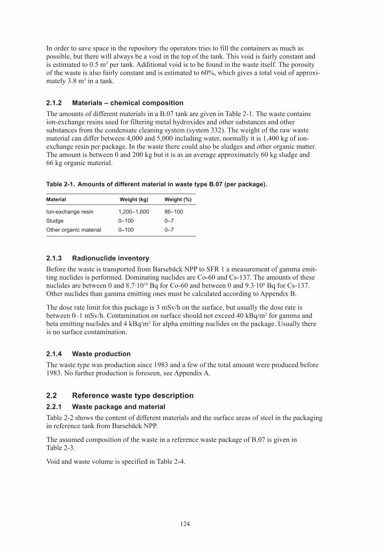
124
In order to save space in the repository the operators tries to fill the containers as much as possible, but there will always be a void in the top of the tank. This void is fairly constant and is estimated to 0.5 m3 per tank. Additional void is to be found in the waste itself. The porosity of the waste is also fairly constant and is estimated to 60%, which gives a total void of approxi-mately 3.8 m3 in a tank.
2.1.2 Materials – chemical compositionThe amounts of different materials in a B.07 tank are given in Table 2-1. The waste contains ion-exchange resins used for filtering metal hydroxides and other substances and other substances from the condensate cleaning system (system 332). The weight of the raw waste material can differ between 4,000 and 5,000 including water, normally it is 1,400 kg of ion-exchange resin per package. In the waste there could also be sludges and other organic matter. The amount is between 0 and 200 kg but it is as an average approximately 60 kg sludge and 66 kg organic material.
Table 2‑1. Amounts of different material in waste type B.07 (per package).
Material Weight (kg) Weight (%)
Ion-exchange resin 1,200–1,600 86–100Sludge 0–100 0–7Other organic material 0–100 0–7
2.1.3 Radionuclide inventoryBefore the waste is transported from Barsebäck NPP to SFR 1 a measurement of gamma emit-ting nuclides is performed. Dominating nuclides are Co-60 and Cs-137. The amounts of these nuclides are between 0 and 8.7·1010 Bq for Co-60 and between 0 and 9.3·109 Bq for Cs-137. Other nuclides than gamma emitting ones must be calculated according to Appendix B.
The dose rate limit for this package is 3 mSv/h on the surface, but usually the dose rate is between 0–1 mSv/h. Contamination on surface should not exceed 40 kBq/m2 for gamma and beta emitting nuclides and 4 kBq/m2 for alpha emitting nuclides on the package. Usually there is no surface contamination.
2.1.4 Waste productionThe waste type was production since 1983 and a few of the total amount were produced before 1983. No further production is foreseen, see Appendix A.
2.2 Reference waste type description2.2.1 Waste package and materialTable 2-2 shows the content of different materials and the surface areas of steel in the packaging in reference tank from Barsebäck NPP.
The assumed composition of the waste in a reference waste package of B.07 is given in Table 2-3.
Void and waste volume is specified in Table 2-4.

125
Table 2‑2. Typical packaging composition and surface area and thickness of components in a concrete tank.
Material Weight (kg) Surface area (m2) Thickness (mm)
Steel in reinforcement 647 40 8Rubber lining 50 2Concrete 10,300 150
Table 2‑3. Estimated reference waste composition in one concrete tank.
Material Weight (kg) Weight (%)
Ion-exchange resin 1,400 92Sludge 60 4Other organic material 66 4
Table 2‑4. Volumes in one of B.07 concrete tanks.
Volume one package (m3)
Waste 2.2Void 3.8
2.2.2 Radionuclide inventoryThe radionuclide composition of a reference waste package is calculated from the amount of Co-60 and Cs-137 in the waste according to Appendix B. The reference inventory in one pack-age at the time of production is presented in Table 2-5.
A reference waste package of the type B.07 has a surface dose rate of 3 mSv/h and no surface contamination.
Table 2‑5. Radionuclide composition of a reference waste package of the type B.07.
Nuclide Activity (Bq) Nuclide Activity (Bq)
Correlated to Co-60 Correlated to PuCo-60 3.3E+10 Pu-239 5.7E+03Cl-36 2.0E+04 Pu-240 1.1E+04Ag-108m 2.0E+06 U-232 5.1E–01Ba-133 3.3E+05 U-234 1.7E+01Be-10 2.0E+01 U-235 5.5E+02C-14 9.8E+07 U-236 4.7E+02Fe-55 3.3E+10 U-238 4.1E+02H-3 3.3E+06 Np-237 2.8E+03Ho-166m 1.3E+05 Pu-238 1.8E+04Mo-93 3.3E+04 Pu-241 1.7E+06Nb-93m 3.3E+07 Pu-242 5.1E+01Nb-94 3.3E+05 Am-241 1.3E+04

126
Nuclide Activity (Bq) Nuclide Activity (Bq)
Ni-59 3.3E+07 Am-242m 1.7E+02Ni-63 2.6E+09 Am-243 5.1E+02Sb-125 3.1E+09 Cm-243 3.4E+02Zr-93 3.3E+04 Cm-244 1.0E+04
Cm-245 5.1E+00Correlated to Cs-137 Cm-246 1.4E+00Cs-137 2.0E+09Cd-113m 1.2E+06Cs-134 7.7E+08Cs-135 2.0E+04Eu-152 1.4E+05Eu-154 2.0E+08Eu-155 1.4E+08I-129 6.0E+03Pd-107 2.0E+03Pm-147 1.8E+09Ru-106 9.9E+06Se-79 7.9E+03Sm-151 6.0E+06Sn-126 9.9E+02Sr-90 2.0E+08Tc-99 1.8E+06
2.3 Uncertainties• GeneraluncertaintiesaredescribedinSection1.3.
• Voidinconcretetankaccordingtoporosityisestimatedtobeintherange60–75%.

127
3 O.07
3.1 Waste type description3.1.1 Waste packageGeneralThe O.07 waste type consists of a concrete tank containing de-watered ion-exchange resins. The raw waste material consists of ion-exchange resins, filter aids and sludge generated at the Oskarshamn nuclear power plant. The material is classified as low level waste. All data comes from /Ingemansson 1999, Johansson 2000, Triumf 2007/.
The physical properties and chemical conditions can vary a lot, but the following restrictions are always applicable:
• ThegeneralrestrictionslistedinSection1.1.
PackagingThe tank is a concrete container with the outer dimensions of 3.3×1.3×2.3 m, see Figure 3-1. The thickness of the concrete wall is 0.15 m. The concrete weight is approximately 10,300 kg and the weight of steel in the package is approximately 647 kg. The reinforcement bars have a thickness of 8 mm which gives the surface of steel to 40 m2. The tank is lined with a 2 mm thick butyl rubber on the inside. The lining weighs 50 kg. The total weight of package is approximately 11,000 kg. The variations between packages are minimal. No major changes in design have been made since the start of production of this package.
Treatment and conditioningThe ion-exchange resin containing metal hydroxides and other substances are pumped into the concrete tank. Then the resins are de-watered by suction through a filter system in the bottom of the tank. The filling and suction cycle is repeated two to three times in order to fill the container with waste. The weight of a tank including waste could be up to 15,000 kg.
Figure 3‑1. A concrete tank.

128
In order to save space in the repository the operators tries to fill the containers as much as possible, but there will always be a void in the top of the tank. This void is fairly constant and is estimated to 0.5 m3 per tank. Additional void is to be found in the waste itself. The porosity of the waste is also fairly constant and is estimated to 60%, which gives a total void of approxi-mately 3.8 m3 in a tank.
3.1.2 Materials – chemical compositionThe amounts of different materials in a O.07 tank are given in Table 3-1. The waste contains ion-exchange resins used for filtering metal hydroxides and other substances from the conden-sate cleaning system (system 332). The weight of the raw waste material can differ between 3,400 and 4,700 including water but it is normally 1,000 kg of ion-exchange resin per package. In the waste there could also be sludges and other organic matter. The amount is between 0 and 200 kg but it is as an average approximately 60 kg sludge and 66 kg organic material. Some trace amounts of complexing agents from detergents etc could be present in this waste type.
Table 3‑1. Amounts of different material in waste type O.07 (per package).
Material Weight (kg) Weight (%)
Ion-exchange resin 850–1,200 81–100Sludge 0–100 0–9Other organic material 0–100 0–9
3.1.3 Radionuclide inventoryBefore the waste is transported from Oskarshamn NPP to SFR 1 a measurement of gamma emit-ting nuclides is performed. Dominating nuclides are Co-60 and Cs-137. The amounts of these nuclides are between 0 and 4.9·1011 Bq for Co-60 and between 0 and 6.1·1011 Bq for Cs-137. Other nuclides than gamma emitting ones must be calculated according to Appendix B.
The dose rate limit for this package is 10 mSv/h on the surface, but usually the dose rate is between 0 and 4 mSv/h. Contamination on surface should not exceed 40 kBq/m2 for gamma and beta emitting nuclides and 4 kBq/m2 for alpha emitting nuclides on the package. Usually there is no surface contamination.
3.1.4 Waste productionThe waste type has been in production since before 1988 and is still in production. The annual production is estimated to 8, see Appendix A.
3.2 Reference waste type description3.2.1 Waste package and materialTable 3-2 shows the content of different materials and the surface areas of steel in the packaging in reference tank from Oskarshamn NPP.
The assumed composition of the waste in a reference waste package of O.07 is given in Table 3-3.
Void and waste volume is specified in Table 3-4.

129
Table 3‑2. Typical packaging composition and surface area and thickness of components in a concrete tank.
Material Weight (kg) Surface area (m2) Thickness (mm)
Steel in reinforcement 647 40 8Rubber lining 50 2Concrete 10,300 150
Table 3‑3. Estimated reference waste composition in one concrete tank.
Material Weight (kg) Weight (%)
Ion-exchange resin 1,000 89Sludge 60 5Other organic material 66 6
Table 3‑4. Volumes in one typical O.07 concrete tanks.
Volume one package (m3)
Waste 2.2Void 3.8
3.2.2 Radionuclide inventoryThe radionuclide composition of a reference waste package is calculated from the amount of Co-60 and Cs-137 in the waste according to Appendix B. The reference inventory in one pack-age at the time of production is presented in Table 3-5.
A reference waste package of the type O.07 has a surface dose rate of 3 mSv/h and no surface contamination.
Table 3‑5. radionuclide composition of a reference waste package of the type O.07.
Nuclide Activity (Bq) Nuclide Activity (Bq)
Correlated to Co-60 Correlated to PuCo-60 4.9E+10 Pu-239 1.1E–05Cl-36 2.9E+04 Pu-240 1.1E–04Ag-108m 2.9E+06 U-232 5.5E+02Ba-133 4.9E+05 U-234 3.8E+02Be-10 2.9E+01 U-235 1.2E+03C-14 1.5E+08 U-236 1.3E+03Fe-55 4.9E+10 U-238 9.2E+05H-3 4.9E+06 Np-237 5.5E+07Ho-166m 1.9E+05 Pu-238 1.6E+03Mo-93 4.9E+04 Pu-241 2.6E+05Nb-93m 4.9E+07 Pu-242 5.5E+03Nb-94 4.9E+05 Am-241 1.6E+04

130
Nuclide Activity (Bq) Nuclide Activity (Bq)
Ni-59 4.9E+07 Am-242m 7.6E+02Ni-63 3.9E+09 Am-243 4.3E+05Sb-125 6.3E+09 Cm-243 1.6E+02Zr-93 4.9E+04 Cm-244 4.4E+01
Cm-245 3.8E–04Correlated to Cs-137 Cm-246 5.5E+05Cs-137 1.7E+10Cd-113m 1.0E+07Cs-134 8.4E+09Cs-135 1.7E+05Eu-152 1.2E+06Eu-154 1.7E+09Eu-155 1.2E+09I-129 5.0E+04Pd-107 1.7E+04Pm-147 1.5E+10Ru-106 8.3E+07Se-79 6.6E+04Sm-151 5.0E+07Sn-126 8.3E+03Sr-90 1.8E+05Tc-99 3.7E+05
3.3 Uncertainties• Voidinconcretetankaccordingtoporosityisestimatedtobeintherange60–75%.

131
4 S.13
4.1 Waste type description4.1.1 Waste packageGeneralThe S.13 waste type consists of a ordinary 200 litre steel drums with ashes from the Studsvik incineration facility. The interior of the 200 litre drum consists of a 100 litre drum and concrete filling between the two drums. The waste material consists of ashes which is a residue after incineration of low level waste as textiles, plastics and wood. The waste could also contain some fragments of scrap metals. The raw waste comes from the operations in Studsvik but also from all of the Swedish nuclear power plants. Some raw waste comes from medical and non-nuclear industrial sources. The material is classified as low level waste /Andersson and Aggeryd 1990, Johansson 2000, Triumf 2007/.
Following restrictions are always applicable on this waste:
• ThegeneralrestrictionslistedinSection1.1.
PackagingThe drum is a standard 200 litre (more precise 218 l) steel drum with the outer dimensions height 0.84 m and diameter 0.57 m. The thickness of the walls are 1 mm and it weighs 20 kg. The inner drum is a 100 litre (precise 113 l) drum with the height 0.70 m and the diameter 0.46 m. The thickness of the walls is 1 mm and it weighs 10 kg. The space between the drums are filled with concrete, the content of cement in the concrete is 20% by weight. A picture of a 200 l steel drum can be seen in Figure 4-1.
The variations between packages are minimal. No major changes in design has been made since the start of production of this package. In the beginning of production of this waste type second-hand drums were used as outer package, which has resulted in small differences in the dimensions of the packages. The variations are a few centimetres on height and diameter. Nowadays only new drums are used in the process.
Figure 4‑1. View of a S.13 outer drum 218 l.

132
Treatment and conditioningThe Waste material is packed in the inner drum after incineration. The inner drum is then placed inside the outer drum, which is already fitted with the concrete lining. Wet concrete is then poured on top of the inner drum as a lid.
Average void is estimated to 5% in a package including inner and outer steel drums.
4.1.2 Materials – chemical compositionThe amounts of different materials in a S.13 drum are given in Table 4-1. Even though the waste is ashes the composition can change from time to time depending on what kind of origin and from where the waste are coming from. The content of waste in an individual package can vary compared to an average package. The amount of aluminium and other metals have been analysed in a batch sample of ash with different size of particles /Lidberg-Berg and Chyssler 2000/.
The weight of ash in the waste matrix is normally 70 kg per conditioned drum. Weight of the total package varies between 300 and 450 kg. About 6.5 kg of these average 70 kg ashes is approximately aluminium according to the analysis. The variations are huge depending on origin of the raw waste.
Table 4‑1. Amounts of different material in waste type S.13 (per package).
Material Weight (kg) Surface area (m2) Weight (%)
Ashes 60–100 19–30Aluminium 0–10 0–3.6 0–3Concrete 230–250 70–75Steel 30–40 7.1–12.7 9–14
4.1.3 Radionuclide inventoryBefore the waste is transported from Studsvik to SFR 1 a measurement of gamma emitting nuclides is performed. Dominating nuclides are Co-60 and Cs-137. The amount of these nuclides are between 0 and 9.5·108 Bq for Co-60 and between 0 and 3.5·108 Bq for Cs-137. Other nuclides than gamma emitting ones must be calculated according to Appendix B.
The dose rate limit for this package is 2 mSv/h on the surface, but usually the dose rate is between 0 and 1 mSv/h. Contamination on surface should not exceed 40 kBq/m2 for gamma and beta emitting nuclides and 4 kBq/m2 for alpha emitting nuclides on the package. Usually there is no surface contamination.
4.1.4 Waste productionThe waste type has been in production since 1980 and is still in production. The annual produc-tion is estimated to 15, see Appendix A.
4.2 Reference waste type description4.2.1 Waste package and materialTable 4-2 shows the content of different materials and the surface areas of steel in the packaging in reference drum from Studsvik.

133
The assumed composition of the waste in a reference waste package of S.13 is given in Table 4-3. The surface area on the aluminium fraction in the waste are calculated as the area for spheres with a diameter of 4 mm, and a density of 2,700 kg/m3.
Void and waste volume is specified in Table 4-4.
Table 4‑2. Estimated typical packaging composition and surface area and thickness of components in waste type S.13.
Component Material Weight (kg) Surface area (m2) Thickness (mm)
Inner steel drum Carbon steel 10 2.7 1Outer steel drum Carbon steel 20 4.4 1
Concrete 240*
* A review of materials in waste type S.13 was made after the values in SAFE project calculations was chosen. The review has led to revised value for concrete. The value used in the calculations for concrete are 29 kg cement/package. Content in above listed value is 48 kg cement (0.20·240 = 48 kg).
Table 4‑3. Estimated reference waste composition in one drum.
Material Weight (kg) Surface area (m2)
Ashes 63.5Aluminium 6.5 3.6
Table 4‑4. Volumes in one typical waste packages of S.13 drums of ashes.
Volume one package (m3)
Waste 0.107Void 0.006
4.2.2 Radionuclide inventoryThe radionuclide composition of a reference waste package is calculated from the amount of Co-60 and Cs-137 in the waste according to Appendix B. The reference inventory in one pack-age at the time of production is presented in Table 4-5a and b.
A reference waste package of the type S.13 has a surface dose rate of 2 mSv/h and no surface contamination.
Table 4‑5a. Radionuclide composition of a reference waste package of the type S.13 from Studsvik.
Nuclide Activity (Bq) Nuclide Activity (Bq)
Correlated to Co-60 Correlated to PuCo-60 1.3E+07 Pu-239 1.7E–06Cl-36 8.0E+00 Pu-240 1.7E–05Ag-108m 3.4E+03 U-232 8.5E+01Ba-133 1.3E+02 U-234 2.5E+01Be-10 8.0E-03 U-235 3.4E+01

134
Nuclide Activity (Bq) Nuclide Activity (Bq)
C-14 4.0E+04 U-236 3.4E+01Fe-55 1.3E+07 U-238 4.2E+04H-3 1.3E+03 Np-237 8.5E+06Ho-166m 5.3E+01 Pu-238 2.5E+02Mo-93 1.3E+01 Pu-241 1.7E+05Nb-93m 1.3E+04 Pu-242 8.5E+02Nb-94 1.3E+02 Am-241 2.5E+03Ni-59 1.3E+04 Am-242m 1.7E+03Ni-63 1.1E+06 Am-243 4.2E+04Sb-125 1.5E+06 Cm-243 2.5E+01Zr-93 1.3E+01 Cm-244 6.8E+00
Cm-245 5.9E–05Correlated to Cs-137 Cm-246 4.2E+04Cs-137 4.8E+06Cd-113m 2.9E+03Cs-134 2.5E+06Cs-135 4.8E+01Eu-152 8.3E+05Eu-154 7.4E+05Eu-155 3.3E+05I-129 1.4E+01Pd-107 4.8E+00Pm-147 4.3E+06Ru-106 4.6E+05Se-79 1.9E+01Sm-151 1.4E+04Sn-126 2.4E+00Sr-90 2.8E+04Tc-99 5.6E+04
Table 4‑6b. Radionuclide composition of a reference waste package of the type S.13 from Svafo.
Nuclide Activity (Bq) Nuclide Activity (Bq)
Correlated to Co-60 Correlated to PuCo-60 3.0E+07 Pu-239 3.8E–06Cl-36 1.8E+01 Pu-240 3.8E–05Ag-108m 1.8E+03 U-232 1.9E+02Ba-133 3.0E+02 U-234 5.6E+01Be-10 1.8E–02 U-235 7.5E+01C-14 8.9E+04 U-236 7.5E+01Fe-55 3.0E+07 U-238 9.4E+04H-3 3.0E+03 Np-237 1.9E+07Ho-166m 1.2E+02 Pu-238 5.6E+02Mo-93 3.0E+01 Pu-241 3.8E+05Nb-93m 3.0E+04 Pu-242 1.9E+03Nb-94 3.0E+02 Am-241 5.6E+03Ni-59 3.0E+04 Am-242m 3.8E+03

135
Nuclide Activity (Bq) Nuclide Activity (Bq)
Ni-63 2.4E+06 Am-243 9.3E+04Sb-125 3.0E+06 Cm-243 5.6E+01Zr-93 3.0E+01 Cm-244 1.5E+01
Cm-245 1.3E–04Correlated to Cs-137 Cm-246 9.4E+04Cs-137 9.3E+06Cd-113m 5.6E+03Cs-134 4.4E+06Cs-135 9.3E+01Eu-152 5.1E+04Eu-154 1.1E+06Eu-155 6.5E+05I-129 2.8E+01Pd-107 9.3E+00Pm-147 8.4E+06Ru-106 7.6E+04Se-79 3.7E+01Sm-151 2.8E+04Sn-126 4.7E+00Sr-90 6.2E+04Tc-99 1.3E+05
4.3 Uncertainties• GeneraluncertaintiesaredescribedinSection1.3.
• Wastevolumeinindividualpackagesdependsonsizeoffragmentsoftheresidualashes.
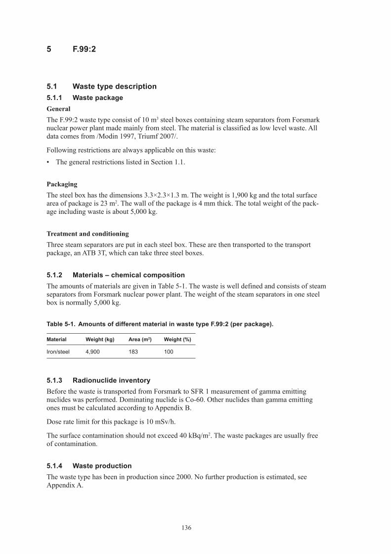
136
5 F.99:2
5.1 Waste type description5.1.1 Waste packageGeneralThe F.99:2 waste type consist of 10 m3 steel boxes containing steam separators from Forsmark nuclear power plant made mainly from steel. The material is classified as low level waste. All data comes from /Modin 1997, Triumf 2007/.
Following restrictions are always applicable on this waste:
• ThegeneralrestrictionslistedinSection1.1.
PackagingThe steel box has the dimensions 3.3×2.3×1.3 m. The weight is 1,900 kg and the total surface area of package is 23 m2. The wall of the package is 4 mm thick. The total weight of the pack-age including waste is about 5,000 kg.
Treatment and conditioningThree steam separators are put in each steel box. These are then transported to the transport package, an ATB 3T, which can take three steel boxes.
5.1.2 Materials – chemical compositionThe amounts of materials are given in Table 5-1. The waste is well defined and consists of steam separators from Forsmark nuclear power plant. The weight of the steam separators in one steel box is normally 5,000 kg.
Table 5‑1. Amounts of different material in waste type F.99:2 (per package).
Material Weight (kg) Area (m2) Weight (%)
Iron/steel 4,900 183 100
5.1.3 Radionuclide inventoryBefore the waste is transported from Forsmark to SFR 1 measurement of gamma emitting nuclides was performed. Dominating nuclide is Co-60. Other nuclides than gamma emitting ones must be calculated according to Appendix B.
Dose rate limit for this package is 10 mSv/h.
The surface contamination should not exceed 40 kBq/m2. The waste packages are usually free of contamination.
5.1.4 Waste productionThe waste type has been in production since 2000. No further production is estimated, see Appendix A.

137
5.2 Reference waste type description5.2.1 Waste package and materialTable 5-2 shows the content of different materials and the steel surface areas of the packaging in the reference package.
The assumed composition of the waste in the reference waste packages of F.99:2 is given in Table 5-3.
The estimated volumes of the waste, the packaging materials and the void volume inside the package for a reference package are given in Table 5-4. The waste volume is estimated from the weights of the waste components in Table 5-3 and approximate densities of the different material. Average void is estimated to 5% in a package.
Void and waste volume is specified in Table 5-4.
Table 5‑2. Estimated reference packaging composition, surface area and thickness of components in F.99:2.
Component Material Weight (kg) Surface area (m2) Thickness (mm)
Steel box Steel 1,900 23 4
Table 5‑3. Estimated reference waste composition and surface area of components in one F.99:2.
Material Weight (kg) Surface area (m2)
Iron/steel 3,000 159
Table 5‑4. Volumes in one reference waste packages of F.99:2.
Volume one package (m3)
Waste 9.5Void 0.5
5.2.2 Radionuclide inventoryThe radionuclide composition of a reference waste package is calculated from the amount of Co-60 and Cs-137 in the waste according to Appendix B. The reference inventory in one pack-age at the time of production is presented in Table 5-5.
A reference waste package of the type F.99:2 has a maximum surface dose rate of 10 mSv/h and no surface contamination.
Table 5‑5. Radionuclide composition of a reference waste package of the type F.99:2.
Nuclide Activity (Bq) Nuclide Activity (Bq)
Correlated to Co-60 Correlated to PuCo-60 2.8E+11 Pu-239 1.7E+06Cl-36 1.7E+05 Pu-240 3.5E+06Ag-108m 1.7E+07 U-232 1.6E+02Ba-133 2.8E+06 U-234 5.2E+03

138
Nuclide Activity (Bq) Nuclide Activity (Bq)
Be-10 1.7E+02 U-235 1.1E+02C-14 2.0E+05 U-236 1.6E+03Fe-55 1.7E+10 U-238 2.1E+03H-3 2.8E+07 Np-237 3.2E+04Ho-166m 1.1E+06 Pu-238 6.5E+06Mo-93 2.8E+05 Pu-241 5.2E+08Nb-93m 2.8E+08 Pu-242 1.6E+04Nb-94 2.8E+06 Am-241 5.2E+06Ni-59 2.8E+08 Am-242m 5.2E+04Ni-63 5.1E+10 Am-243 1.6E+05Sb-125 2.8E+10 Cm-243 1.1E+05Zr-93 2.8E+05 Cm-244 1.1E+06
Cm-245 1.6E+03Correlated to Cs-137 Cm-246 4.2E+02Cs-137 –*Cd-113m –*Cs-134 –*Cs-135 –*Eu-152 –*Eu-154 –*Eu-155 –*I-129 –*Pd-107 –*Pm-147 –*Ru-106 –*Se-79 –*Sm-151 –*Sn-126 –*Sr-90 –*Tc-99 –*
* Too few measurements to give an estimate.
5.3 Uncertainties• GeneraluncertaintiesaredescribedinSection1.3.

139
6 O.99:1
6.1 Waste type description6.1.1 Waste packageGeneralThe O.99:1 type consists of 40 concrete moulds from Oskarshamn. They were originally the same type as O.01:9 and O.02:9, but due to fractures in the moulds they needed special treatment. The waste contains ion exchange resins and the moulds have been put in specially designed cortén boxes due to the fractures. The material is classified as low level waste. All data comes from /Ingemansson 2001, Triumf 2007/.
The following restrictions are always applicable:
• ThegeneralrestrictionslistedinSection1.1.
PackagingThe fractured concrete moulds have been put in specially designed cortén boxes. These boxes are made from 5 mm thick cortén sheet metal with the measurements of 1.49 m length, 1.49 m width and 1.6 m height. The weight of an empty cortén box is approximately 960 kg. The maximum allowed weight is 7,500 kg.
Treatment and conditioningThe concrete moulds have been put in cortén boxes. When the mould has been put into the box it is provided with a lid. When it is to be disposed of in SFR the boxes will be opened and the moulds grouted to minimise the void volume.
6.1.2 Materials – chemical compositionThe amounts of different materials in O.99:1 are given in Table 6-1.
The waste is fairly well defined and consists mainly of ion-exchange resins. The weight of the raw waste material is approximated to 150 kg waste per package, see Table 6-1.
Table 6‑1. Amounts of different material in waste type O.99:1 (per package).
Material Weight (kg) Area (m2) Weight (%)
Cellulose 8.3 0.6Iron/steel 1,221 38 89.8Ion exchange resins 130 9.6
6.1.3 Radionuclide inventoryBefore the waste is transported from Oskarshamn to SFR 1 a measurement of gamma emitting nuclides is performed. Dominating nuclides are Co-60 and Cs-137. The amounts of these nuclides are approximately 1.6·1010 Bq for Co-60 and 2.7·1010 Bq for Cs-137. Other nuclides than gamma emitting ones must be calculated according to Appendix B.
Dose rate limit for this package is 2 mSv/h but normally it is around 0.2 mSv/h on the surface. The surface contamination should not exceed 40 kBq/m2 for gamma and beta and 4 kBq/m2 for alpha emitting nuclides. The waste packages are usually free of contamination.

140
6.1.4 Waste productionThe original concrete moulds were made in Oskarshamn in the beginning of 1970. They were reconditioned in 1979. No further production is foreseen, see Appendix A.
6.2 Reference waste type description6.2.1 Waste package and materialTable 6-2 shows the content of different materials and the steel surface areas of the packaging in the reference packages.
The assumed composition of the waste in the reference waste packages of O.99:1 is given in Table 6-3.
The estimated volumes of the waste, the packaging materials and the void volume inside the package for a reference package are given in Table 6-4. The waste volume is estimated from the weights of the waste components in Table 6-3 and approximate densities of the different material. Average void is estimated to 5% in a package.
Void and waste volume is specified in Table 6-4.
Table 6‑2. Estimated reference packaging composition, surface area and thickness of components in O.99:1.
Component Material Weight (kg) Surface area (m2) Thickness (mm)
Steel box Steel 960 38 5
Table 6‑3. Estimated reference waste composition in one O.99:1.
Material Weight (kg)
Cellulose 8.3Iron/steel 261Ion exchange resin 130
Table 6‑4. Volumes in one reference waste packages of O.99:1.
Volume one package (m3)
Waste 3.37Void 0.18
6.2.2 Radionuclide inventoryThe radionuclide composition of a reference waste package is calculated from the amount of Co-60 and Cs-137 in the waste according to Appendix B. The reference inventory in one pack-age at the time of production is presented in Table 6-5.
A reference waste package of the type O.99:1 has a maximum surface dose rate of 2 mSv/h and no surface contamination.

141
Table 6‑5. Radionuclide composition of a reference waste package of the type O.99:1.
Nuclide Activity (Bq) Nuclide Activity (Bq)
Correlated to Co-60 Correlated to PuCo-60 1.6E+10 Pu-239 2.9E+06Cl-36 2.8E+05 Pu-240 5.9E+06Ag-108m 9.8E+05 U-232 8.8E+01Ba-133 1.6E+05 U-234 2.9E+03Be-10 9.8E+00 U-235 5.9E+01C-14 1.6E+07 U-236 8.8E+02Fe-55 1.6E+10 U-238 1.2E+03H-3 1.6E+06 Np-237 1.2E+03Ho-166m 6.5E+05 Pu-238 7.5E+06Mo-93 8.2E+05 Pu-241 2.9E+08Nb-93m 1.6E+07 Pu-242 8.8E+03Nb-94 1.6E+05 Am-241 7.5E+06Ni-59 1.6E+07 Am-242m 2.9E+04Ni-63 3.3E+09 Am-243 8.8E+04Sb-125 1.6E+09 Cm-243 5.9E+04Zr-93 1.6E+05 Cm-244 8.8E+06
Cm-245 8.8E+02Correlated to Cs-137 Cm-246 2.3E+02Cs-137 2.8E+10Cd-113m 1.7E+07Cs-134 2.8E+10Cs-135 1.4E+05Eu-152 1.9E+06Eu-154 2.8E+09Eu-155 1.9E+09I-129 8.3E+03Pd-107 2.8E+04Pm-147 2.5E+10Ru-106 1.4E+08Se-79 1.1E+05Sm-151 8.3E+07Sn-126 1.4E+04Sr-90 2.8E+09Tc-99 1.4E+08
6.3 Uncertainties• GeneraluncertaintiesaredescribedinSection1.3.

142
7 R.99:1
7.1 Waste type description7.1.1 Waste packageGeneralThe R.99:1 waste is an old reactor tank lid from Ringhals 2 nuclear power plant. The material is classified as low level waste. All data comes from /Ekenved 1997, Triumf 2007/.
The following restrictions are always applicable:
• ThegeneralrestrictionslistedinSection1.1.
PackagingThe lid is being fitted with hauling equipment but not packed any further. The waste weighs about 65,000 kg, has a diameter of 4.7 m and a height of 3.2 m with the protective cap.
Treatment and conditioningThe lid is being decontaminated on the outside and after that painted as an extra precautionary measure. The lid is then being provided with a protective cap made from steel with a thickness of 6 mm.
7.1.2 Materials – chemical compositionThe amount of material in R.99:1 is given in Table 7-1.
Table 7‑1. Amounts of different material in waste type R.99:1 (per package).
Material Weight (kg) Area (m2) Weight (%)
Iron/steel 65,000 150 100
7.1.3 Radionuclide inventoryBefore the waste is transported from Ringhals to SFR 1 a measurement of gamma emitting nuclides is being performed. Before the waste is transported from Ringhals to SFR 1 a measure-ment of gamma emitting nuclides is performed. Dominating nuclides are Co-60 and Co-58 and Ni-63. Other nuclides than gamma emitting ones must be calculated according to Appendix B.
Dose rate limit for this package is 10 mSv/h upon placement in SFR 1. The surface contamina-tion should not exceed 40 kBq/m2 for gamma and beta and 4 kBq/m2 for alpha emitting nuclides. The waste packages are usually free of contamination.
7.1.4 Waste productionThe waste type was in production 1996. No further production is foreseen, see Appendix A.
7.2 Reference waste type description7.2.1 Waste package and materialThe waste type dopes not have a waste package per see. The reactor tank lid is grouted with concrete to fill in the void.

143
7.2.2 Radionuclide inventoryThe radionuclide composition of a reference waste package is calculated from the amount of Co-60 and Cs-137 in the waste according to Appendix B. The reference inventory in one pack-age at the time of production is presented in Table 7-2.
Table 7‑2. Radionuclide composition of a reference waste package of the type R.99:1.
Nuclide Activity (Bq) Nuclide Activity (Bq)
Correlated to Co-60 Correlated to PuCo-60 2.8E+11 Pu-239 1.0E+07Cl-36 1.7E+05 Pu-240 2.1E+07Ag-108m 1.7E+07 U-232 6.2E+02Ba-133 2.8E+06 U-234 2.1E+04Be-10 1.7E+02 U-235 4.2E+02C-14 8.4E+08 U-236 6.2E+03Fe-55 2.8E+11 U-238 8.3E+03H-3 2.8E+07 Np-237 8.3E+03Ho-166m 1.1E+06 Pu-238 8.3E+07Mo-93 2.8E+05 Pu-241 2.1E+09Nb-93m 2.8E+08 Pu-242 6.2E+04Nb-94 2.8E+06 Am-241 2.1E+07Ni-59 2.8E+08 Am-242m 2.1E+05Ni-63 2.2E+10 Am-243 6.2E+05Sb-125 2.8E+10 Cm-243 4.2E+05Zr-93 2.8E+05 Cm-244 6.2E+07
Cm-245 6.2E+03Correlated to Cs-137 Cm-246 1.7E+03Cs-137 –*Cd-113m –*Cs-134 –*Cs-135 –*Eu-152 –*Eu-154 –*Eu-155 –*I-129 –*Pd-107 –*Pm-147 –*Ru-106 –*Se-79 –*Sm-151 –*Sn-126 –*Sr-90 –*Tc-99 –*
* Too few measurements to give an estimate.
7.3 Uncertainties• GeneraluncertaintiesaredescribedinSection1.3.

144
8 Other waste types
The waste types R.01, R.10 and R.23 are put both in BTF and BMA. For further information about them, see Appendix E.
Since SFR 1 still is in operation there is always the possibility that new waste types are needed. It is not possible to define these types per se

145
9 References
Andersson L, Aggeryd I, 1990. Typbeskrivning av avfallskollin från Studsvik Betongkring-gjuten Aska i plåtfat (typ 13). Studsvik RadWaste, Arbetsrapport Nr RW-89/62.
Berntsson J, 1991. Typbeskrivning av avfallskollin. Avvattnad pulverjonbytarmassa och filterhjälpmedel i betongtank. Sydkraft Barsebäcksverket Rapport PBD-8702-11.
Ekenved M, 1997. Avfallsbeskrivning för udda avfall: Reaktortanklock från R2, rapport 1263/96.
Ingemansson K-E, 1999. Oskarshamnsverket – Typbeskrivning avfallstyp O.07, av betongtank innehållande avvattnad pulverformig jonbytarmassa och filterhjälpmedel. OKG Instruktion avfall I-0784.
Ingemansson K-E, 2001. Avfallsbeskrivning för kokill i corténlåda. OKG 2000-06610.
Johansson C, 2000. Beräkningsunderlag för normalkollin. SKB Drift PM 2000/15.
Lidberg-Berg K, Chyssler J, 2000. Tungmetaller i lågaktiv aska från förbränningsanlägg-ningen i Studsvik. Studsvik RadWaste Arbetsrapport RW-00/42.
Modin U, 1997. Avfallsbeskrivning för udda avfall: Ångseparatorer från Forsmark 1 och 2. FKA rapport 97/028.
Triumf, 2007. Triumf – database over radioactive operational waste in SFR 1 [accessed February 2007].

147
Appendix E
Waste types in BMA
1 General 1511.1 Waste in BMA 1511.2 Definitions 1511.3 Uncertainties 152
2 B.05 1532.1 Waste type description 153
2.1.1 Waste package 1532.1.2 Materials – chemical composition 1532.1.3 Radionuclide inventory 1542.1.4 Waste production 154
2.2 Reference waste type description 1542.2.1 Waste package and material 1542.2.2 Radionuclide inventory 155
2.3 Uncertainties 156
3 F.05 1573.1 Waste type description 157
3.1.1 Waste package 1573.1.2 Materials – chemical composition 1573.1.3 Radionuclide inventory 1583.1.4 Waste production 158
3.2 Reference waste type description 1583.2.1 Waste package and material 1583.2.2 Radionuclide inventory 159
3.3 Uncertainties 160
4 F.15 1614.1 Waste type description 161
4.1.1 Waste package 1614.1.2 Materials – chemical composition 1614.1.3 Radionuclide inventory 1624.1.4 Waste production 162
4.2 Reference waste type description 1624.2.1 Waste package and material 1624.2.2 Radionuclide inventory 163
4.3 Uncertainties 164
5 F.17 1655.1 Waste type description 165
5.1.1 Waste package 1655.1.2 Materials – chemical composition 1655.1.3 Radionuclide inventory 1665.1.4 Waste production 166
5.2 Reference waste type description 1665.2.1 Waste package and material 1665.2.2 Radionuclide inventory 167
5.3 Uncertainties 168

148
6 F.23 1696.1 Waste type description 169
6.1.1 Waste package 1696.1.2 Materials – chemical composition 1696.1.3 Radionuclide inventory 1706.1.4 Waste production 170
6.2 Reference waste type description 1706.2.1 Waste package and material 1706.2.2 Radionuclide inventory 172
6.3 Uncertainties 173
7 O.01 1747.1 Waste type description 174
7.1.1 Waste package 1747.1.2 Materials – chemical composition 1757.1.3 Radionuclide inventory 1757.1.4 Waste production 175
7.2 Reference waste type description 1757.2.1 Waste package and material 1757.2.2 Radionuclide inventory 176
7.3 Uncertainties 177
8 C.01 1788.1 Waste type description 178
8.1.1 Waste package 1788.1.2 Materials – chemical composition 1798.1.3 Radionuclide inventory 1798.1.4 Waste production 179
8.2 Reference waste type description 1798.2.1 Waste package and material 1798.2.2 Radionuclide inventory 180
8.3 Uncertainties 181
9 O.23 1829.1 Waste type description 182
9.1.1 Waste package 1829.1.2 Materials – chemical composition 1829.1.3 Radionuclide inventory 1839.1.4 Waste production 183
9.2 Reference waste type description 1839.2.1 Waste package and material 1839.2.2 Radionuclide inventory 184
9.3 Uncertainties 185
10 C.23 18610.1 Waste type description 186
10.1.1 Waste package 18610.1.2 Materials – chemical composition 18610.1.3 Radionuclide inventory 18710.1.4 Waste production 187
10.2 Reference waste type description 18710.2.1 Waste package and material 18710.2.2 Radionuclide inventory 188
10.3 Uncertainties 189

149
11 R.01 19011.1 Waste type description 190
11.1.1 Waste package 19011.1.2 Materials – chemical composition 19011.1.3 Radionuclide inventory 19111.1.4 Waste production 191
11.2 Reference waste type description 19111.2.1 Waste package and material 19111.2.2 Radionuclide inventory 192
11.3 Uncertainties 193
12 R.10 19412.1 Waste type description 194
12.1.1 Waste package 19412.1.2 Materials – chemical composition 19412.1.3 Radionuclide inventory 19512.1.4 Waste production 195
12.2 Reference waste type description 19512.2.1 Waste package and material 19512.2.2 Radionuclide inventory 196
12.3 Uncertainties 196
13 R.15 19713.1 Waste type description 197
13.1.1 Waste package 19713.1.2 Materials – chemical composition 19713.1.3 Radionuclide inventory 19813.1.4 Waste production 198
13.2 Reference waste type description 19813.2.1 Waste package and material 19813.2.2 Radionuclide inventory 199
13.3 Uncertainties 200
14 R.23 20114.1 Waste type description 201
14.1.1 Waste package 20114.1.2 Materials – chemical composition 20114.1.3 Radionuclide inventory 20214.1.4 Waste production 202
14.2 Reference waste type description 20214.2.1 Waste package and material 20214.2.2 Radionuclide inventory 203
14.3 Uncertainties 205
15 R.29 20615.1 Waste type description 206
15.1.1 Waste package 20615.1.2 Materials – chemical composition 20615.1.3 Radionuclide inventory 20615.1.4 Waste production 207
15.2 Reference waste type description 20715.2.1 Waste package and material 20715.2.2 Radionuclide inventory 207
15.3 Uncertainties 208

150
16 S.09 20916.1 Waste type description 209
16.1.1 Waste package 20916.1.2 Materials – chemical composition 20916.1.3 Radionuclide inventory 21016.1.4 Waste production 210
16.2 Reference waste type description 21016.2.1 Waste package and material 21016.2.2 Radionuclide inventory 211
16.3 Uncertainties 212
17 S.23 21317.1 Waste type description 213
17.1.1 Waste package 21317.1.2 Materials – chemical composition 21317.1.3 Radionuclide inventory 21417.1.4 Waste production 214
17.2 Reference waste type description 21417.2.1 Waste package and material 21417.2.2 Radionuclide inventory 215
17.3 Uncertainties 216
18 F.99:1 21718.1 Waste type description 217
18.1.1 Waste package 21718.1.2 Materials – chemical composition 21718.1.3 Radionuclide inventory 21718.1.4 Waste production 218
18.2 Reference waste type description 21818.2.1 Waste package and material 21818.2.2 Radionuclide inventory 218
18.3 Uncertainties 219
19 Other waste types 220
20 References 221

151
1 General
1.1 Waste in BMAIn SFR, in the BMA – rock cavern for intermediate level waste – short-lived wastes from the nuclear power plants and the Studsvik research site are disposed off. The BMA cavern is approximately 160 m long, 19.5 m wide and has a height of 16.5 m. Inside the cavern a concrete construction has been raised. The construction consists of 13 big and 2 smaller compartments. The big ones is 10 m · 15 m · 8 m and the small ones 4 m · 7.2 m · 4.8 m. The waste, moulds and drums, are placed in the compartments by remote controlled equipment. When a compartment is filled a lid is built upon the waste. There is also a possibility to back-fill the void between the waste packages in a compartment. The technical barriers are basically the concrete structure that will minimise flow through the waste and lead the ground-water flow around the construction.
The waste that is intended in BMA comes from many different waste streams but the most important one is ion-exchange resins from the nuclear power plants. Other waste like metal components of different origin and contaminated ordinary garbage is also disposed off in BMA.
The dose rates allowed on packages are maximum 100 mSv/h. The amount of radionuclides are fairly low, BMA has been designed to handle approximately 6% of the radionuclides in SFR 1. Dominating nuclide are Co-60 and Cs-137.
Other criteria for acceptance are:
• Construction,geometry,dimensionsandweightmustbesuitedtothehandlingsysteminSFR and the transportation system in general and in BLA in particular. The strength of the packages must be sufficient to withstand normal and abnormal handling.
• Eachpackagemusthaveanindividualidentityandtheradionuclidecontentofgammaemitting nuclides shall be known.
• Surfacecontaminationshouldnotexceed40kBq/m2 for gamma and beta emitting nuclides and 4 kBq/m2 for alpha emitting nuclides.
• Theinternaldoseratesandintegrateddosemustnotaffectthebarrierpropertiesintherepository.
• Thechemicalandphysicalpropertiesandthestructureofthewasteshouldbeknown.
• Chemicalaggressiveorexplosivematerial,pressurisedgasandfreeliquidarenotallowed.
• Gasproductionfromthewastemustnotbetobig.
• Thewasteshallhaveenoughresistancetowardscorrosionthattheintegrityofthepackageis kept until sealing of the repository.
• Burnablewastemustnotbesubjecttoself-ignition.
• Complexingagentsshouldifpossiblebeavoided.
All waste in BMA is normally packed in concrete or steel moulds or steel drums.
1.2 DefinitionsSurface area is defined as the area subject to anaerobic corrosion and gas production after seal-ing of the repository.

152
1.3 Uncertainties
• Thepresentedwastetypesdescribesthetypesthathasbeen,isinorcanbeforeseentobeproduced in Sweden. New waste types may be present in the future.
• Almostalldataisbasedonliteraturevalues,smallerchangesmaynotbeenproperlydocumented.
• Allfutureproductionisbasedonarelativesimpleprognosismodel.Thismodel,describedin Appendix A, was chosen since the uncertainties about processes etc are large.
• Noregardhasbeentakentoimprovementsinprocessesetc.
• Areferencepackagehasbeenchosenbasedonbestestimates.Actualpackagesmaydifferconsiderably from this reference package, the uncertainty for the whole population of pack-ages is judged to be smaller.
• BigcomponentsasheatexchangersetccouldinthefuturebeofinteresttodisposeoffinBMA. See Chapter 19 in this appendix.
• Fortheradionuclideinventoryforeachwastepackagetheamountpresentediseitherbasedon the amount received from correlation factors or actual measurements when applicable. When there is a difference between different sub types of waste packages within one waste type the inventory presented in this appendix is the most conservative one.
• Voidpresentedinthisreportisbasedonbestestimates,theestimatescanbequitecrude.
• Tc-99iscorrelatedagainstbothCo-60andCs-137whenquantifyingtheinventories,according to Appendix B. In the tables “Radionuclide composition of a reference waste package” however Tc-99 is presented as only correlated towards Cs-137.
Figure 1‑1. BMA.

153
2 B.05
2.1 Waste type description2.1.1 Waste packageGeneralThe B.05 waste type consists of a standard 200-litre drum containing ion-exchange resins in a bitumen matrix. The raw waste material consists of ion-exchange resins and sludges generated at the Barsebäck nuclear power plant. The material is classified as intermediate level waste. All data comes from /Berntsson 1991, Johansson 2000, Triumf 2007/.
The physical properties and chemical conditions are well known. The following restrictions are always applicable:
• ThegeneralrestrictionslistedinSection1.1.
• Sincethepackagecontainsburnablesubstancestherestrictionsregardingself-ignitionetcare of special importance.
This waste type is more or less identical to the B.06-type except the radionuclide content.
PackagingThe steel drum is made of stainless steel with diameter 0.595 m and 0.882 m in height. The thickness of the material is 1.2 mm. The drum weighs approximately 23 kg and the surface area is approximately 3 m2. To facilitate the handling in SFR the drums are placed four by four on a steel plate with the dimension 1.2×1.2 m and the thickness of 0.004 m. The weight of the steel plate is 49 kg with surface area of 2.9 m2. The variations between packages are minimal. No major changes in design have been made since the start of production of this package except that since 1985 the drums are made of stainless steel. The weight in total of a package including waste and is approximately 200 kg. The maximum allowed weight of a waste package is 500 kg.
Treatment and conditioningThe ion exchange resin containing metal hydroxides and other substances are mixed with bitu-men in a custom-made facility in the Barsebäck NPP. The flow in the bitumenisation process is measured with electrical conductivity. A small amount of Na2SO4 is mixed with the product to give correct measurements of the conductivity. Emulgator is added in order to make the product more homogene. After filling, a steel lid is placed upon the drum. The drums are placed on the steel plate when they are sent to SFR.
The void varies but is estimated to 0.03 m3 in a drum (not including expansion box).
2.1.2 Materials – chemical compositionThe amounts of different materials in a B.05 drum are given in Table 2-1. The waste matrix contains metal hydroxides from the clean-up system for the reactor and evaporation residues from back flush water from the fuel storage pools. The weight of the raw waste material is normally 50 kg ion exchange resin per package but varies, see Table 2-1.
The matrix is made of bitumen. The specific brand of bitumen has changed during the many years of production of this waste type but it is always of the distilled sort. The brands used are: Mexphalate until 1982, Nynäs industrial bitumen IB 45 between 1983–1995 and Nynäs industrial bitumen IB 55 used from 1995. The amounts of added chemicals are:Na2SO4 0.2–0.5 kg/drum Emulgator 0.4–1.1 kg/drum

154
Table 2‑1. Amounts of different material in waste type B.05 (per package).
Material Weight (kg) Weight (%)
Ion-exchange resin 30–55 16–43 Bitumen 129–155 57–84
2.1.3 Radionuclide inventoryBefore the waste is transported from Barsebäck NPP to SFR 1 a measurement of gamma emit-ting nuclides is performed. Dominating nuclides are Co-60 and Cs-137. The amounts of these nuclides are between 0 and 5.1·1011 Bq for Co-60 and between 0 and 1.1·1011 Bq for Cs-137. Other nuclides than gamma emitting ones must be calculated according to Appendix B.
The dose rate limit for this package is 100 mSv/h but normally it is between 0–10 mSv/h on 1 m. The surface contamination should not exceed 40 kBq/m2 for gamma and beta and 4 kBq/m2 for alpha emitting nuclides. The waste packages are usually free of contamination.
2.1.4 Waste productionThe waste type has been in production since 1985. No further production is foreseen, see Appendix A.
2.2 Reference waste type description2.2.1 Waste package and materialTable 2-2 shows the content of different materials and the surface areas of the packaging in B.05 package from Barsebäck. Since the steel plate and expansion box is shared between four drums ¼ of the plate and box is included in a package of B.05.
The assumed composition of the waste in a reference waste package of B.05 is given in Table 2-3.
Void and waste volume is specified in Table 2-4.
Average void is estimated to 0.03 m3 in a steel drum.
Table 2‑2. Estimated reference packaging composition and surface area and thickness of components in each steel drum and one ¼ of a steel plate of B.05.
Component Material Weight (kg) Surface area (m2) Thickness (mm)
Steel drum Stainless steel 23 3 1.2Steel plate Carbon steel 12.25 0.7 4Expansion box Carbon steel 5 0.2 6
Table 2‑3. Estimated reference waste composition in one steel drum of B.05.
Material Weight (kg)
Ion-exchange resin 50Bitumen 150Chemicals(Na-sulphate) 0.5

155
Table 2‑4. Volumes in one packages of steel drums including ¼ steel plate per drum of B.05.
Volume one package (m3)
Waste 0.2Void 0.03
2.2.2 Radionuclide inventoryThe radionuclide composition of a reference waste package is calculated from the amount of Co-60 and Cs-137 in the waste according to Appendix B. The reference inventory in one pack-age at the time of production is presented in Table 2-5.
A reference waste package of the type B.05 has a surface dose rate of 100 mSv/h and no surface contamination.
Table 2‑5. Radionuclide composition of a reference waste package of the type B.05.
Nuclide Activity (Bq) Nuclide Activity (Bq)
Correlated to Co-60 Correlated to PuCo-60 9.8E+09 Pu-239 6.2E+03Cl-36 5.9E+03 Pu-240 1.3E+04Ag-108m 5.9E+05 U-232 5.6E–01Ba-133 9.8E+04 U-234 1.9E+01Be-10 5.9E+00 U-235 6.0E+02C-14 2.9E+07 U-236 5.2E+02Fe-55 9.8E+09 U-238 4.4E+02H-3 9.8E+05 Np-237 3.1E+03Ho-166m 3.9E+04 Pu-238 2.0E+04Mo-93 9.8E+03 Pu-241 1.9E+06Nb-93m 9.8E+06 Pu-242 5.6E+01Nb-94 9.8E+04 Am-241 1.4E+04Ni-59 9.8E+06 Am-242m 1.9E+02Ni-63 7.8E+08 Am-243 5.6E+02Sb-125 9.5E+08 Cm-243 3.7E+02Zr-93 9.8E+03 Cm-244 1.1E+04
Cm-245 5.6E+00Correlated to Cs-137 Cm-246 1.5E+00Cs-137 4.7E+09Cd-113m 2.8E+06Cs-134 1.1E+08Cs-135 4.7E+04Eu-152 3.3E+05Eu-154 4.7E+08Eu-155 3.3E+08I-129 1.4E+04Pd-107 4.7E+03Pm-147 4.3E+09Ru-106 2.4E+07Se-79 1.9E+04

156
Nuclide Activity (Bq) Nuclide Activity (Bq)
Sm-151 1.4E+07Sn-126 2.4E+03Sr-90 4.7E+08Tc-99 4.3E+06
2.3 Uncertainties• GeneraluncertaintiesaredescribedinSection1.3.

157
3 F.05
3.1 Waste type description3.1.1 Waste packageGeneralThe F.05 waste type consists of a standard 200-litre drum containing ion-exchange resins in a bitumen matrix. The raw waste material consists of ion-exchange resins generated at the Forsmark nuclear power plant. The material is classified as intermediate level waste. All data comes from /Lindberg and Malmkvist 1991ab, Johansson 2000, Triumf 2007/.
The physical properties and chemical conditions are well known. The following restrictions are always applicable:
• ThegeneralrestrictionslistedinSection1.1.
• Sincethepackagecontainsburnablesubstancestherestrictionsregardingself-ignitionetcare of special importance.
PackagingThe steel drum is made of stainless steel with diameter 0.595 m and 0.882 m in height. The wall thickness is 1.2 mm. The drum weighs approximately 25 kg and surface area is approximately 2.5 m2. To facilitate the handling in SFR the drums are placed four by four on a steel plate with the dimension 1.2×1.2 m and the thickness of 4 mm. The weight of the steel plate is 66.5 kg with surface area of 3.9 m2. The variations between packages are minimal. No major changes in design have been made since the start of production of this package.
The weight in total of a package including waste and is approximately 250 kg but varies between 115 and 350 kg. The maximum allowed weight of a waste package is 500 kg.
Treatment and conditioningThe ion-exchange resins containing metal hydroxides and other substances are mixed with bitu-men in a custom-made facility in the Forsmark NPP. After filling, the drums are topped up with a small amount of bitumen and then a steel lid is placed upon the drum. The drums are placed on the steel plate when the drums are sent to SFR.
The void varies but is estimated to 0.03 m3 in a drum.
3.1.2 Materials – chemical compositionThe amounts of different materials in a F.05 drum are given in Table 3-1. The waste contains metal hydroxides from condensate cleaning up system (system 332), system drainage (342) and small amounts from fuel pool cleaning system (324). Some trace amounts of complexing agents from cleaning products could
follow this waste stream. The weight of the raw waste material is normally 130 kg ion-exchange resin per package but varies, see Table 3-1.
The matrix is made of bitumen. The brand used is Nynäs industrial bitumen according to /Lindberg and Malmkvist 1991ab/.
No interval for different material is specified in the literature.

158
Table 3‑1. Amounts of different material in waste type F.05 (per package).
Material Weight (kg) Weight (%)
Ion-exchange resin 130 58Bitumen 95 42
3.1.3 Radionuclide inventoryBefore the waste is transported from Forsmark NPP to SFR 1 a measurement of gamma emitting nuclides is performed. Dominating nuclides are Co-60 and Cs-137. The amounts of these nuclides are between 0 and 3·1010 Bq for Co-60 and between 0 and 2·109 Bq for Cs-137. Other nuclides than gamma emitting ones must be calculated according to Appendix B.
The dose rate limit for this package is 100 mSv/h but normally it is between 0–2 mSv/h on 1 metre. The surface contamination should not exceed 40 kBq/m2 for gamma and beta and 4 kBq/m2 for alpha emitting nuclides. The waste packages are usually free of contamination.
3.1.4 Waste productionThe waste type has been in production from 1982 to 1990. No further production is foreseen, see Appendix A.
3.2 Reference waste type description3.2.1 Waste package and materialTable 3-2 shows the content of different materials and the surface areas of the packaging in F.05 package from Forsmark. Since the steel plate is shared between four drums ¼ of the plate and box is included in a package of F.05.
The assumed composition of the waste in a reference waste package of F.05 is given in Table 3-3.
Void and waste volume is specified in Table 3-4.
Average void is estimated to 0.02 m3 in a steel drum.
Table 3‑2. Estimated reference packaging composition and surface area and thickness of components in each steel drum and one ¼ of a steel plate of F.05.
Component Material Weight (kg) Surface area (m2) Thickness (mm)
Steel drum Stainless steel 25 2.5 1.25Steel plate Stainless steel 16.6 0.98 4
Table 3‑3. Estimated reference waste composition in one steel drum of F.05.
Material Weight (kg)
Ion-exchange resin 130Bitumen 95

159
Table 3‑4. Volumes in one waste packages of steel drums including ¼ steel plate per drum of F.05.
Volume one package (m3)
Waste 0.195Void 0.02
3.2.2 Radionuclide inventoryThe radionuclide composition of a reference waste package is calculated from the amount of Co-60 and Cs-137 in the waste according to Appendix B. The reference inventory in one pack-age at the time of production is presented in Table 3-5.
A reference waste package of the type F.05 has a surface dose rate of 30 mSv/h and no surface contamination.
Table 3‑5. Radionuclide composition of a reference waste package of the type F.05.
Nuclide Activity (Bq) Nuclide Activity (Bq)
Correlated to Co-60 Correlated to PuCo-60 5.7E+09 Pu-239 9.3E+03Cl-36 3.4E+03 Pu-240 1.9E+04Ag-108m 3.4E+05 U-232 8.4E–01Ba-133 5.7E+04 U-234 2.8E+01Be-10 3.4E+00 U-235 1.1E+02C-14 1.7E+07 U-236 8.4E+00Fe-55 5.7E+09 U-238 1.2E+02H-3 5.7E+05 Np-237 9.8E+02Ho-166m 2.3E+04 Pu-238 5.4E+04Mo-93 5.7E+03 Pu-241 2.8E+06Nb-93m 5.7E+06 Pu-242 8.4E+01Nb-94 5.7E+04 Am-241 1.5E+04Ni-59 5.7E+06 Am-242m 2.8E+02Ni-63 4.6E+08 Am-243 8.4E+02Sb-125 5.7E+08 Cm-243 2.8E+02Zr-93 5.7E+03 Cm-244 5.1E+04
Cm-245 8.4E+00Correlated to Cs-137 Cm-246 2.2E+00Cs-137 2.0E+07Cd-113m 1.2E+04Cs-134 1.5E+07Cs-135 2.0E+02Eu-152 1.4E+03Eu-154 2.0E+06Eu-155 1.4E+06I-129 6.0E+01Pd-107 2.0E+01Pm-147 1.8E+07Ru-106 1.0E+05

160
Nuclide Activity (Bq) Nuclide Activity (Bq)
Se-79 8.0E+01Sm-151 6.0E+04Sn-126 1.0E+01Sr-90 2.0E+06Tc-99 1.8E+04
3.3 Uncertainties• GeneraluncertaintiesaredescribedinSection1.3.

161
4 F.15
4.1 Waste type description4.1.1 Waste packageGeneralThe F.15 waste type consists of 1.73 m3 steel moulds containing ion-exchange resins in a concrete matrix. The raw waste material consists of ion-exchange resins, filter aids and evaporator residues generated at the Forsmark nuclear power plant. The material is classified as intermediate level waste. All data comes from /Lindberg and Malmkvist 1991c, Johansson 2000, Triumf 2007/.
Following restrictions are always applicable on this waste:
• ThegeneralrestrictionslistedinSection1.1.
Packaging
The mould is a cubic box made of steel with the dimensions 1.2×1.2×1.2 m. The wall is 5 mm thick, the bottom is 6 mm thick. The mould weighs approximately 425 kg and the surface area is approximately 20 m2. The variations between moulds are minimal. No major change in design has been made since the start of production of this package.
The weight in total of a package including waste and is approximately 2,400 kg but differs between 2,300–3,100 kg. The maximum allowed weight of a waste package is 5,000 kg.
Treatment and conditioningThe waste, used ion-exchange resin, is heated and then mixed with water and cement additives. The slurry is then pumped into the mould and cement is added. When the cement is added the stirrer is started and the waste matrix is mixed. The matrix is then allowed to harden. A steel lid is placed upon the mould.
4.1.2 Materials – chemical compositionThe amounts of different materials in a F.15 mould are given in Table 4-1. The waste is well defined and consists of ion-exchange resins, evaporator residues and filter-aid with radio-nuclides.
The waste includes powder resins and filter-aids from cleaning of condensate (system 332), system drainage (system 342/1), cleaning of floor drainage (system 342/2) and bead resins from, system drainage (system 342/1) and evaporator residues from system 342/5. Some resins from other systems can be present if the radionuclide content is low enough.
The weight of the raw waste material is normally 536 kg of waste per package but varies, see Table 4-1.
The matrix is made of cement, standard Portland type. Silix GP and Sika AER are used as additives.

162
Table 4‑1. Amounts of different material in waste type F.15 (per package)
Material Weight (kg) Weight (%)
Ion-exchange resin 355–550 24.8–41.7Evaporator residues 0–200 0–15.1Cement* 770–875 50.7–71.1
* Including water 0.4 kg/kg cement.
4.1.3 Radionuclide inventoryBefore the waste is transported from Forsmark NPP to SFR 1 a measurement of gamma emitting nuclides is performed. Dominating nuclides are Co-60 and Cs-137. The amounts of these nuclides are between 0 and 5·109 Bq for Co-60 and between 0 and 5·109 Bq for Cs-137. Other nuclides than gamma emitting ones must be calculated according to Appendix B.
The dose rate limit for this package is 100 mSv/h on the surface. Normally the dose rate at 1 metre is 0–0.1 mSv/h. The surface contamination should not exceed 40 kBq/m2 for gamma and beta and 4 kBq/m2 for alpha emitting nuclides on the package. The waste packages are usually free of contamination.
4.1.4 Waste productionThe waste type was in production between 1981 and 1988. No more production is foreseen, see Appendix A.
4.2 Reference waste type description4.2.1 Waste package and materialTable 4-2 shows the content of different materials and the steel surface areas of the packaging in a reference package.
The assumed composition of the waste in a reference waste package of F.15 is given in Table 4-3.
The estimated volumes of the waste, the packaging materials and the void volume inside the package for a reference package are given in Table 4-4. The waste volume is estimated from the weights of the waste components in Table 4-3 and approximate densities of the different material. Average void is estimated to 10% in a package.
Void and waste volume is specified in Table 4-4.
Table 4‑2. Estimated reference packaging composition and surface area and thickness of components in concrete mould of F.15.
Component Material Weight (kg) Surface area (m2) Thickness (mm)
Steel box Stainless steel 400 17 5Stirrer Stainless steel 25 3 2

163
Table 4‑3. Estimated reference waste composition and surface area and thickness of components in one of F.15.
Material Weight (kg)
Ion-exchange resin 375Evaporator concentrates 161Cement* 805
* Including 0.4 kg water/kg cement.
Table 4‑4. Volumes in one packages of F.15.
Volume in one (m3)
Waste 1.53Void 0.17
4.2.2 Radionuclide inventoryThe radionuclide composition of a reference waste package is calculated from the amount of Co-60 and Cs-137 in the waste according to Appendix B. The reference inventory in one package at the time of production is presented in Table 4-5. The transuranic elements have been calculated in a different way and it is not possible to calculate a reference waste type.
A reference waste package of the type F.15 has a surface dose rate of 30 mSv/h and no surface contamination.
Table 4‑5. Radionuclide composition of a reference waste package of the type F.15.
Nuclide Activity (Bq) Nuclide Activity (Bq)
Correlated to Co-60 Correlated to PuCo-60 3.4E+09 Pu-239 5.6E+03Cl-36 2.1E+03 Pu-240 1.1E+04Ag-108m 2.1E+05 U-232 5.0E–01Ba-133 3.4E+04 U-234 1.7E+01Be-10 2.1E+00 U-235 6.6E+01C-14 1.0E+07 U-236 5.0E+00Fe-55 3.4E+09 U-238 7.2E+01H-3 3.4E+05 Np-237 5.9E+02Ho-166m 1.4E+04 Pu-238 3.2E+04Mo-93 3.4E+03 Pu-241 1.7E+06Nb-93m 3.4E+06 Pu-242 5.0E+01Nb-94 3.4E+04 Am-241 9.2E+03Ni-59 3.4E+06 Am-242m 1.7E+02Ni-63 2.8E+08 Am-243 5.0E+02Sb-125 3.4E+08 Cm-243 1.7E+02Zr-93 3.4E+03 Cm-244 3.1E+04
Cm-245 5.0E+00Correlated to Cs-137 Cm-246 1.3E+00Cs-137 2.2E+09Cd-113m 1.3E+06Cs-134 5.5E+08
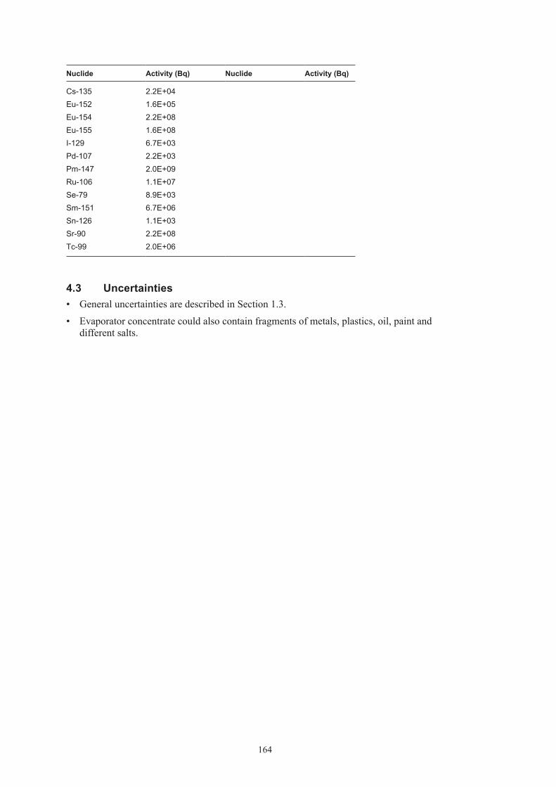
164
Nuclide Activity (Bq) Nuclide Activity (Bq)
Cs-135 2.2E+04Eu-152 1.6E+05Eu-154 2.2E+08Eu-155 1.6E+08I-129 6.7E+03Pd-107 2.2E+03Pm-147 2.0E+09Ru-106 1.1E+07Se-79 8.9E+03Sm-151 6.7E+06Sn-126 1.1E+03Sr-90 2.2E+08Tc-99 2.0E+06
4.3 Uncertainties• GeneraluncertaintiesaredescribedinSection1.3.
• Evaporatorconcentratecouldalsocontainfragmentsofmetals,plastics,oil,paintanddifferent salts.

165
5 F.17
5.1 Waste type description5.1.1 Waste packageGeneralThe F.17 waste type consists of 1.73 m3 steel moulds containing ion-exchange resins in a bitumen matrix. The raw waste material consists of ion-exchange resins, filter aids and evaporator concentrates generated at the Forsmark nuclear power plant. The material is classified as inter mediate level waste. All data comes from /Lindberg and Malmkvist 1999, Johansson 2000, Triumf 2007/.
Following restrictions are always applicable on this waste:
• ThegeneralrestrictionslistedinSection1.1.
• Sincethepackagecontainsburnablesubstancestherestrictionsregardingself-ignitionetcare of special importance.
PackagingThe mould is a cubic box made of steel with the dimensions 1.2×1.2×1.2 m. The wall is 5 mm thick, the bottom is 6 mm thick. The mould weighs approximately 400 kg and the surface area is approximately 10 m2. The variations between moulds are minimal. No major change in design has been made since the start of production of this package.
The weight in total of a package including waste and is approximately 2,080 kg but differs between 1,900–2,250 kg. The maximum allowed weight of a waste package is 5,000 kg.
Treatment and conditioningThe ion-exchange resins are dried in 150°C in a conical dryer and are then homogenised with bitumen in a conical mixer. The mixed waste is then poured in a steel mould. Each batch is maximum 500 litres. The mix is then allowed to cool for at least 17 h before a thin layer (~ 1 cm) of pure bitumen is poured upon the waste matrix. The waste package is thereafter lidded with a steel lid.
The void varies but is estimated to 10% in a package.
5.1.2 Materials – chemical compositionThe amounts of different materials in a F.17 mould are given in Table 5-1. The waste is well defined and consists of ion-exchange resins, filter aids and evaporator concentrates with radionuclides from system 342. The weight of the raw waste material is normally 770 kg waste per package but varies, see Table 5-1. Until 1992 the waste type F.17 contained filter aids based on cellulose, each package until this year is estimated to have an average of 3.6 kg cellulose per package. In total there is 195 packages with this amount of cellulose /Carlsson 2001/.
The matrix is made of bitumen. The specific brand of bitumen has changed during the years of production of this waste type but it is always the distilled kind. The brands used are Nynäs industrial bitumen IB 45 or IB 55.

166
Table 5‑1. Amounts of different material in waste type F.17 (per package).
Material Weight (kg) Weight (%)
Ion-exchange resin 0–1,100 0–65Evaporator concentrate 0–1,100 0–65Bitumen 600–680 35–40
5.1.3 Radionuclide inventoryBefore the waste is transported from Forsmark NPP to SFR 1 a measurement of gamma emitting nuclides is performed. Dominating nuclides are Co-60 and Cs-137. The amounts of these nuclides are between 0 and 5·1011 Bq for Co-60 and between 0 and 2·1011 Bq for Cs-137. Other nuclides than gamma emitting ones must be calculated according to Appendix B.
The dose rate limit for this package is 100 mSv/h. Normal dose rate at 1 m is between 0.1–4.5 mSv/h. The surface contamination should not exceed 40 kBq/m2 for gamma and beta and 4 kBq/m2 for alpha emitting nuclides on the package. The waste packages are usually free of contamination.
5.1.4 Waste productionThe waste type has been in production since 1989 and is still in production. Annual production is estimated to 30 packages per year, see Appendix A.
5.2 Reference waste type description5.2.1 Waste package and materialTable 5-2 shows the content of different materials and the steel surface areas of the packaging in a reference package. The assumed composition of the waste in a reference waste package of F.17 is given in Table 5-3.
Average void is estimated 10% in a steel mould. Void and waste volume is specified in Table 5-4.
Table 5‑2. Estimated reference packaging composition and surface area and thickness of components in steel mould of F.17.
Component Material Weight (kg) Surface area (m2) Thickness (mm)
Steel mould Stainless steel 400 10 5
Table 5‑3. Estimated reference waste composition in one of F.17.
Material Weight (kg)
Ion-exchange resin 650Evaporator concentrates 120Bitumen 820

167
Table 5‑4. Volumes in one reference waste package of F.17.
Volume in one (m3)
Waste 1.615Void 0.085
5.2.2 Radionuclide inventoryThe radionuclide composition of a reference waste package is calculated from the amount of Co-60 and Cs-137 in the waste according to Appendix B. The reference inventory in one pack-age at the time of production is presented in Table 5-5.
A reference waste package of the type F.17 has a surface dose rate of 100 mSv/h and no surface contamination.
Table 5‑5. Radionuclide composition of a reference waste package of the type F.17.
Nuclide Activity (Bq) Nuclide Activity (Bq)
Correlated to Co-60 Correlated to PuCo-60 6.7E+10 Pu-239 1.1E+05Cl-36 4.0E+04 Pu-240 2.3E+05Ag-108m 4.0E+06 U-232 1.0E+01Ba-133 6.7E+05 U-234 3.4E+02Be-10 4.0E+01 U-235 1.3E+03C-14 2.0E+08 U-236 1.0E+02Fe-55 6.7E+10 U-238 1.5E+03H-3 6.7E+06 Np-237 1.2E+04Ho-166m 2.7E+05 Pu-238 6.5E+05Mo-93 6.7E+04 Pu-241 3.4E+07Nb-93m 6.7E+07 Pu-242 1.0E+03Nb-94 6.7E+05 Am-241 1.9E+05Ni-59 6.7E+07 Am-242m 3.4E+03Ni-63 5.3E+09 Am-243 1.0E+04Sb-125 6.6E+09 Cm-243 3.4E+03Zr-93 6.7E+04 Cm-244 6.2E+05
Cm-245 1.0E+02Correlated to Cs-137 Cm-246 2.7E+01Cs-137 8.2E+09Cd-113m 4.9E+06Cs-134 2.9E+09Cs-135 8.2E+04Eu-152 5.7E+05Eu-154 8.2E+08Eu-155 5.7E+08I-129 2.5E+04Pd-107 8.2E+03Pm-147 7.4E+09Ru-106 4.1E+07

168
Nuclide Activity (Bq) Nuclide Activity (Bq)
Se-79 3.3E+04Sm-151 2.5E+07Sn-126 4.1E+03Sr-90 8.2E+08Tc-99 7.4E+06
5.3 Uncertainties• GeneraluncertaintiesaredescribedinSection1.3.
• Evaporatorconcentratecouldalsocontainfragmentsofmetals,plastics,oil,paintanddifferent salts.
• Dataoncelluloseinfilteraidsuntil1992isprobablyoverestimated.

169
6 F.23
6.1 Waste type description6.1.1 Waste packageGeneralThe F.23 waste type consists of 1.73 m3 concrete or steel moulds with scrap metal and refuse in a concrete matrix. The raw waste material consists of mainly iron/steel, cellulose and other organics generated at the Forsmark nuclear power plant. The material is classified as intermedi-ate level waste. All data comes from /Forsmark 2000, Johansson 2000, Triumf 2007/.
Following restrictions are always applicable on this waste:
• ThegeneralrestrictionslistedinSection1.1.
Packaging
The steel mould has the dimension 1.2×1.2×1.2 m. The weight is 445 kg and the total metal surface area of package is 14.5 m2. The wall of the package is 5 mm thick, the bottom is 6 mm thick. The mould also has two lids and some reinforcements. The variations between moulds are minimal. Total weight of package including waste is approximately 2,100 kg but differs between 1,470–4,270 kg.
The concrete mould is a cubic box made of reinforced concrete with the dimensions 1.2×1.2×1.2 m. The walls are 10 cm thick. The reinforcement is made of 12 mm steel bars with a total surface of 10 m2. The mould weighs approximately 1,600 kg. The variations between moulds are minimal. Total weight of package including waste is approximately 2,400 kg but differs between 2,200–4,100 kg.
In some special cases a concrete mould with 25 cm thick walls can be used.
The maximum allowed weight of a waste package is 5,000 kg.
Treatment and conditioningWaste from the power plant is sorted in compactable and non-compactable. Non-compactable is put directly in a mould and the mould is then filled with concrete. Compactable waste is put in the mould and compacted. A ‘middle-lid’ is placed in the mould to prevent re-expansion of the waste. This operation is repeated until the mould is full. Then the mould is filled with concrete.
Pouring concrete on top of the package makes a lid.
6.1.2 Materials – chemical compositionThe amounts of different materials in a F.23 mould are given in Table 6-1. The waste is fairly well defined and consists mainly of scrap metal and refuses as
filters, wood, cloth, plastics and cables. The weight of the raw waste material is normally 770 kg waste per package but varies, see Table 6-1a and b.
The matrix is made of concrete. The brand used is of the standard Portland.

170
Table 6‑1a. Amounts of different material in waste type F.23 steel mould (per package).
Material Weight (kg)* Area (m2) Weight (%)
Sludges 18 0.8Cellulose 150 7.0Other organic material 450 21.1Iron/steel 150 7.6 7.0Aluminium 5 0.5 0.2Concrete** 1,356 63.7
* Variation of amounts of material is not available in referred documents.
** Including 0.13 kg water/kg concrete.
Table 6‑1b. Amounts of different material in waste type F.23 10‑cm concrete mould (per package).
Material Weight (kg)* Area (m2) Weight (%)
Sludges 0 0Cellulose 29 3.6Other organic material 186 23.0Iron/steel 30 1.5 3.7Aluminium 0 0 0Concrete** 565 69.8
* Variation of amounts of material is not available in referred documents.
** Including 0.13 kg water/kg concrete.
6.1.3 Radionuclide inventoryBefore the waste is transported from Forsmark to SFR 1 a measurement of gamma emitting nuclides is performed. Dominating nuclides are Co-60 and Cs-137. The amounts of these nuclides are between 0 and 9·1010 Bq for Co-60 and between 0 and 3·1010 Bq for Cs-137. Other nuclides than gamma emitting ones must be calculated according to Appendix B.
Dose rate limit for this package is 100 mSv/h but normally it is between 0.01–8 mSv/h on 1 m. The surface contamination should not exceed 40 kBq/m2 for gamma and beta and 4 kBq/m2 for alpha emitting nuclides. The waste packages are usually free of contamination.
6.1.4 Waste productionThe waste type has been in production since 1986 and is still in production. Annual production is estimated to 8 packages per year, see Appendix A.
6.2 Reference waste type description6.2.1 Waste package and materialThe steel mould is used as reference waste package.
Table 6-2a and b shows the content of different materials and the steel surface areas of the packaging in the reference packages.
The assumed composition of the waste in the reference waste packages of F.23 is given in Table 6-3a and b.

171
Table 6‑2a. Estimated reference packaging composition, surface area and thickness of components in steel mould of F.23.
Component Material Weight (kg) Surface area (m2) Thickness (mm)
Steel box Steel 400 10 5Lid Steel 48 5.8 3Reinforcement Steel 14 0.5 14
Table 6‑2b. Estimated reference packaging composition, surface area and thickness of components in concrete mould of F.23.
Component Material Weight (kg) Surface area (m2) Thickness (mm)
Concrete box Concrete 1,340 10Lid Steel 13 1.8 2Reinforcement Steel 261 10 12
Table 6‑3a. Estimated reference waste composition and surface area and thickness of components in one steel mould F.23.
Material Weight (kg) Surface area (m2) Thickness (mm)
Sludge 18Cellulose 150Other organic material 450Iron/steel 150 7.8 5Aluminium 5 0.7 5Concrete* 1,356
* Including 0.13 kg water/kg concrete.
Table 6‑3b. Estimated reference waste composition and surface area and thickness of components in one concrete mould F.23.
Material Weight (kg) Surface area (m2) Thickness (mm)
Sludge 0Cellulose 29Other organic material 186Iron/steel 30 1.5 5Aluminium 0 0 5Concrete* 565
* Including 0.13 kg water/kg concrete.
The estimated volumes of the waste, the packaging materials and the void volume inside the package for a reference package are given in Table 6-4. The waste volume is estimated from the weights of the waste components in Table 6-3a and b and approximate densities of the different material. Average void is estimated to 5% in a package. Void and waste volume is specified in Table 6-4.

172
Table 6‑4. Volumes in one package of F.23.
Volume in one (m3)
Waste 1.615Void 0.085
6.2.2 Radionuclide inventoryThe radionuclide composition of a reference waste package is calculated from the amount of Co-60 and Cs-137 in the waste according to Appendix B. The reference inventory in one pack-age at the time of production is presented in Table 6-5a and b.
Table 6‑5a. Radionuclide composition of a reference waste package of the type F.23 concrete mould.
Nuclide Activity (Bq) Nuclide Activity (Bq)
Correlated to Co-60 Correlated to PuCo-60 1.5E+10 Pu-239 3.9E+03Ag-108m 9.0E+05 Pu-240 7.7E+03Ba-133 1.5E+05 U-232 3.5E–01Be-10 9.0E+00 U-234 1.2E+01C-14 4.5E+07 U-235 7.8E+01Fe-55 1.5E+10 U-236 3.5E+00H-3 1.5E+06 U-238 6.0E+01Ho-166m 6.0E+04 Np-237 3.8E+02Mo-93 1.5E+04 Pu-238 1.8E+04Nb-93m 1.5E+07 Pu-241 1.2E+06Nb-94 1.5E+05 Pu-242 3.5E+01Ni-59 1.5E+07 Am-241 5.3E+03Ni-63 1.2E+09 Am-242m 1.2E+02Sb-125 1.5E+09 Am-243 3.5E+02Zr-93 1.5E+04 Cm-243 5.2E–02
Cm-244 6.6E+03Correlated to Cs-137 Cm-245 3.5E+00Cs-137 –* Cm-246 9.3E-01Cd-113m –*Cs-134 –*Cs-135 –*Eu-152 –*Eu-154 –*Eu-155 –*I-129 –*Pd-107 –*Pm-147 –*Ru-106 –*Se-79 –*Sm-151 –*Sn-126 –*Sr-90 –*Tc-99 –*
* Too few measurements to give an estimate.

173
Table 6‑5b. Radionuclide composition of a reference waste package of the type F.23 steel mould.
Nuclide Activity (Bq) Nuclide Activity (Bq)
Correlated to Co-60 Correlated to PuCo-60 1.3E+10 Pu-239 3.2E+03Cl-36 8.0E+03 Pu-240 6.4E+03Ag-108m 8.0E+05 U-232 2.9E–01Ba-133 1.3E+05 U-234 9.7E+00Be-10 8.0E+00 U-235 6.6E+01C-14 4.0E+07 U-236 2.9E+00Fe-55 1.3E+10 U-238 5.0E+01H-3 1.3E+06 Np-237 3.2E+02Ho-166m 5.3E+04 Pu-238 1.5E+04Mo-93 1.3E+04 Pu-241 9.7E+05Nb-93m 1.3E+07 Pu-242 2.9E+01Nb-94 1.3E+05 Am-241 4.7E+06Ni-59 1.3E+07 Am-242m 9.7E+01Ni-63 1.1E+09 Am-243 2.9E+02Sb-125 1.3E+09 Cm-243 4.4E–02Zr-93 1.3E+04 Cm-244 5.6E+03
Cm-245 2.9E+00Correlated to Cs-137 Cm-246 7.8E–01Cs-137 2.2E+08Cd-113m 1.3E+05Cs-134 1.5E+08Cs-135 2.2E+03Eu-152 1.5E+04Eu-154 2.2E+07Eu-155 1.5E+07I-129 6.6E+02Pd-107 2.2E+02Pm-147 2.0E+08Ru-106 1.1E+06Se-79 8.8E+02Sm-151 6.6E+05Sn-126 1.1E+02Sr-90 2.2E+07Tc-99 2.0E+05
A reference waste package of the type F.23 has a surface dose rate of 100 mSv/h and no surface contamination.
6.3 Uncertainties• GeneraluncertaintiesaredescribedinSection1.3.
• AllfutureproductionofF.23isassumedtobeinsteelmoulds.Somepackagesmaybeoftheconcrete kind.

174
7 O.01
7.1 Waste type description7.1.1 Waste packageGeneralThe O.01 waste type consists of 1.73 m3 concrete moulds containing ion-exchange resins and inert filter-aid in a concrete matrix. The raw waste material consists of ion-exchange resins and filter aids generated at the Oskarshamn nuclear power plant. The material is classified as intermediate level waste /Ingemansson 1999, Johansson 2000, Triumf 2007/.
Following restrictions are always applicable on this waste:
• ThegeneralrestrictionslistedinSection1.1.
PackagingThe mould is a cubic box made of reinforced concrete with the dimensions 1.2×1.2×1.2 m. The walls are normally 10 cm thick but can in some exceptional cases be 25 cm thick. The rein-forcement is made of 12 mm steel bars with a total surface of 10 m2. The 10-cm mould weighs approximately 1,600 kg and the 25-cm one weighs about 3,200 kg. A stirrer made of carbon steel is included in the waste package. It weighs 16 kg and has a estimated surface of 1 m2. To avoid cracking of the mould, due to expansion of the concrete matrix, a lining of compactable material (polyethene) is put inside of the mould, the lining has a thickness of 20 mm and a total weight of 10 kg. Lining is only placed in the 10-cm mould. The variations between moulds are minimal.
Some changes in the design have been made since the start of production of this package. 1975–78 the reinforcement was gradually improved and in 1981 a new design of reinforcement was introduced. In 1979 the moulds was fitted with a expansion cassette of polyurethane and wood, this was used until 1988 when the polyethene cassette was introduced. In 1986 a new brand of concrete to make the lid was introduced, instead of Sabema A, the Betokem EXM-4 was used. Today no chemical cement additives is used, earlier Silix GP was used.
The weight of a package including waste is approximately 3,200 kg but differs between 3,300–3,600 kg. The maximum allowed weight of a waste package is 5,000 kg.
Treatment and conditioningThe waste, used ion-exchange resin, is pumped into the mould and cement is added. If needed, water is added. When the cement is added the stirrer is started and the waste matrix is mixed for 30 minutes. The matrix is then allowed to harden for two days. Pouring concrete on top of the matrix then makes a lid. The lid is at least 10 cm thick. The concrete is allowed 24 hours to harden before the waste is transported to intermediate storage.
The waste, used ion-exchange resin, is pumped into the mould and cement is added. If needed, water is added. When the cement is added the stirrer is started and the waste matrix is mixed for 30 minutes. The matrix is then allowed to harden for two days. Pouring concrete on top of the matrix then makes a lid. The concrete is allowed 24 hours to harden before the waste is transported to intermediate storage. The lid is at least 10 cm thick.

175
7.1.2 Materials – chemical compositionThe amounts of different materials in a O.01 mould are given in Table 7-1. The waste is well defined and consists of ion exchange resins and filter-aid with radionuclides from systems for cleaning reactor water (system 331), treatment of liquid waste (system 342), decontamination (system 347) and cleaning of fuel ponds (system 324). Systems 331, 347 and 342 uses bead resin, system 342 uses powder resin. The weight of the raw waste material is normally 130 kg ion exchange resin per package but varies, see Table 7-1.
The matrix is made of cement. The specific brand of cement has changed during the years of production of this waste type. The brands used are: Sabema A-bruk 1970–1986, LH cement 1970–1981, Massiv cement 1981–1986, Anläggningscement 1986–1999, Höghållfasthetscement from 1999– Betokem EXM used from 1986–.
Table 7‑1. Amounts of different material in waste type O.01 (per package).
Material Weight (kg) Weight (%)
Ion-exchange resin 90–150 5.7–10.0Cement* 1,350–1,500 90.0–94.3
* Including water 0.4 kg/kg cement.
7.1.3 Radionuclide inventoryBefore the waste is transported from Oskarshamn NPP to SFR 1 a measurement of gamma emit-ting nuclides is performed. Dominating nuclides are Co-60 and Cs-137. The amounts of these nuclides are between 0 and 6·1011 Bq for Co-60 and between 0 and 9·1011 Bq for Cs-137. Other nuclides than gamma emitting ones must be calculated according to Appendix B.
Dose rate limit for this package is 30 mSv/h but normally it is between 0.01–11 mSv/h on 1 m. The surface contamination should not exceed 40 kBq/m2 for gamma and beta and 4 kBq/m2 for alpha emitting nuclides. The waste packages are usually free of contamination.
7.1.4 Waste productionThe waste type has been in production since 1970. No further production is foreseen, see Appendix A.
7.2 Reference waste type description7.2.1 Waste package and materialTable 7-2 shows the content of different materials and the steel surface areas of the packaging in a reference package.
The assumed composition of the waste in a reference waste package of O.01 is given in Table 7-3.
The estimated volumes of the waste, the packaging materials and the void volume inside the package for a reference package are given in Table 7-4. The waste volume is estimated from the weights of the waste components in Table 7-3 and approximate densities of the different material. Average void is estimated to 15% in a package.
Void and waste volume is specified in Table 7-4.

176
Table 7‑2. Estimated reference packaging composition and surface area and thickness of components in concrete mould of O.01.
Component Material Weight (kg) Surface area (m2) Thickness (mm)
Concrete mould Concrete 1,340 100Reinforcement Steel 261 10 12Steel lid Steel 13 1.8 2Stirrer Steel 16 1 5Other organics Polyethene 10
Table 7‑3. Estimated reference waste composition and surface area and thickness of components in one of O.01.
Material Weight (kg)
Ion-exchange resin 130Cement* 1,540
* Including water 0.4 kg/kg cement.
Table 7‑5. Volumes in one waste package of O.01.
Volume in one (m3)
Waste 0.85Void 0.15
7.2.2 Radionuclide inventoryThe radionuclide composition of a reference waste package is calculated from the amount of Co-60 and Cs-137 in the waste according to Appendix B. The reference inventory in one pack-age at the time of production is presented in Table 7-5.
A reference waste package of the type O.01 has a maximum surface dose rate of 100 mSv/h and no surface contamination.
Table 7‑5. Radionuclide composition of a reference waste package of the type O.01.
Nuclide Activity (Bq) Nuclide Activity (Bq)
Correlated to Co-60 Correlated to PuCo-60 9.2E+10 Pu-239 3.8E+05Cl-36 5.5E+04 Pu-240 7.7E+05Ag-108m 5.5E+06 U-232 3.5E+01Ba-133 9.2E+05 U-234 1.2E+03Be-10 5.5E+01 U-235 1.9E+01C-14 2.8E+08 U-236 8.0E+02Fe-55 9.2E+10 U-238 2.6E+03H-3 9.2E+06 Np-237 2.8E+03Ho-166m 3.7E+05 Pu-238 1.9E+06Mo-93 9.2E+04 Pu-241 1.2E+08Nb-93m 9.2E+07 Pu-242 3.5E+03Nb-94 9.2E+05 Am-241 5.5E+05

177
Nuclide Activity (Bq) Nuclide Activity (Bq)
Ni-59 9.2E+07 Am-242m 1.2E+04Ni-63 7.3E+09 Am-243 3.4E+04Sb-125 1.0E+10 Cm-243 1.6E+03Zr-93 9.2E+04 Cm-244 9.0E+05
Cm-245 3.5E+02Correlated to Cs-137 Cm-246 9.2E+01Cs-137 2.1E+10Cd-113m 1.2E+07Cs-134 1.7E+10Cs-135 2.1E+05Eu-152 1.5E+06Eu-154 2.1E+09Eu-155 1.5E+09I-129 6.2E+04Pd-107 2.1E+04Pm-147 1.9E+10Ru-106 1.0E+08Se-79 8.3E+04Sm-151 6.2E+07Sn-126 1.0E+04Sr-90 2.1E+09Tc-99 1.9E+07
7.3 Uncertainties• NoproductionofO.01isplannedbutproductionispossible.
• GeneraluncertaintiesaredescribedinSection1.3.

178
8 C.01
8.1 Waste type description8.1.1 Waste packageGeneralThe C.01 waste type consists of 1.73 m3 concrete moulds containing ion-exchange resins and inert filter-aid in a concrete matrix. The raw waste material consists of ion-exchange resins and filter aids generated at the Clab facility in Oskarshamn. The material is classified as intermediate level waste /Ingemansson 1999, Johansson 2000, Triumf 2007/.
The C.01 waste type is identical with O.01 with some small exceptions. The type is in everyday use called O.01.
Following restrictions are always applicable on this waste:
• ThegeneralrestrictionslistedinSection1.1.
PackagingThe mould is a cubic box made of reinforced concrete with the dimensions 1.2×1.2×1.2 m. The walls are normally 10 cm thick but can in some exceptional cases be 25 cm thick. The rein-forcement is made of 12 mm steel bars with a total surface of 10 m2. The 10-cm mould weighs approximately 1,600 kg and the 25-cm one weighs about 3,200 kg. A stirrer made of carbon steel is included in the waste package. It weighs 16 kg and has a estimated surface of 1 m2. To avoid cracking of the mould, due to expansion of the concrete matrix, a lining of compactible material (polyethene) is put inside of the mould, the lining has a thickness of 20 mm and a total weight of 10 kg. Lining is only placed in the 10-cm mould. The variations between moulds are minimal.
Some changes in the design have been made since the start of production of this package. 1975–78 the reinforcement was gradually improved and in 1981 a new design of reinforcement was introduced. In 1979 the moulds was fitted with a expansion cassette of polyurethane and wood, this was used until 1988 when the polyethene cassette was introduced. In 1986 a new brand of concrete to make the lid was introduced, instead of Sabema A, the Betokem EXM-4 was used. Today no chemical cement additives is used, earlier Silix GP was used.
The weight of a package including waste is approximately 3,200 kg but differs between 3,300–3,600 kg. The maximum allowed weight of a waste package is 5,000 kg.
Treatment and conditioningThe waste, used ion-exchange resin, is pumped into the mould and cement is added. If needed, water is added. When the cement is added the stirrer is started and the waste matrix is mixed for 30 minutes. The matrix is then allowed to harden for two days. Pouring concrete on top of the matrix then makes a lid. The lid is at least 10 cm thick. The concrete is allowed 24 hours to harden before the waste is transported to intermediate storage. Treatment and conditioning
The waste, used ion-exchange resin, is pumped into the mould and cement is added. If needed, water is added. When the cement is added the stirrer is started and the waste matrix is mixed for 30 minutes. The matrix is then allowed to harden for two days. Pouring concrete on top of the matrix then makes a lid. The concrete is allowed 24 hours to harden before the waste is transported to intermediate storage. The lid is at least 10 cm thick.

179
8.1.2 Materials – chemical compositionThe amounts of different materials in a C.01 mould are given in Table 8-1. The waste is well defined and consists of ion exchange resins and filter-aid with radionuclides from systems for cleaning reactor water (system 331), treatment of liquid waste (system 342), decontamination (system 347) and cleaning of fuel ponds (system 324). Systems 331, 347 and 342 uses bead resin, system 342 uses powder resin. The weight of the raw waste material is normally 130 kg ion exchange resin per package but varies, see Table 8-1.
The matrix is made of cement. The specific brand of cement has changed during the years of production of this waste type. The brands used are: Sabema A-bruk –1986, Massiv cement –1986, Anläggningscement 1986–1999, Höghållfasthetscement from 1999– Betokem EXM used from 1986–.
Table 8‑1. Amounts of different material in waste type C.01 (per package).
Material Weight (kg) Weight (%)
Ion-exchange resin 90–150 5.7–10.0Cement* 1,350–1,500 90.0–94.3
* Including water 0.4 kg/kg cement.
8.1.3 Radionuclide inventoryBefore the waste is transported from Oskarshamn NPP/Clab to SFR 1 a measurement of gamma emitting nuclides is performed. Dominating nuclides are Co-60 and Cs-137. The amounts of these nuclides are between 0 and 6 ·1011 Bq for Co-60 and between 0 and 9 ·1011 Bq for Cs-137. Other nuclides than gamma emitting ones must be calculated according to Appendix B.
Dose rate limit for this package is 30 mSv/h but normally it is between 0.01–30 mSv/h on the surface. The surface contamination should not exceed 40 kBq/m2 for gamma and beta and 4 kBq/m2 for alpha emitting nuclides. The waste packages are usually free of contamination.
8.1.4 Waste productionThe waste type has been in production since 1970 and can still produced, but no further produc-tion is foreseen, see Appendix A.
8.2 Reference waste type description8.2.1 Waste package and materialTable 8-2 shows the content of different materials and the steel surface areas of the packaging in a reference package.
The assumed composition of the waste in a reference waste package of C.01 is given in Table 8-3.
The estimated volumes of the waste, the packaging materials and the void volume inside the package for a reference package are given in Table 8-4. The waste volume is estimated from the weights of the waste components in Table 8-3 and approximate densities of the different material. Average void is estimated to 15% in a package.
Void and waste volume is specified in Table 8-4.

180
Table 8‑2. Estimated reference packaging composition and surface area and thickness of components in concrete mould of C.01.
Component Material Weight (kg) Surface area (m2) Thickness (mm)
Concrete mould Concrete 1,340 100Reinforcement Steel 261 10 12Steel lid Steel 13 1.8 2Stirrer Steel 16 1 5Other organics Polyethene 10
Table 8‑3. Estimated reference waste composition and surface area and thickness of components in one of C.01.
Material Weight (kg)
Ion-exchange resin 130Cement* 1,540
* Including water 0.4 kg/kg cement.
Table 8‑4. Volumes in one reference waste package of C.01.
Volume in one (m3)
Waste 0.85Void 0.15
8.2.2 Radionuclide inventoryThe radionuclide composition of a reference waste package is calculated from the amount of Co-60 and Cs-137 in the waste according to Appendix B. The reference inventory in one pack-age at the time of production is presented in Table 8-5.
A reference waste package of the type C.01 has a maximum surface dose rate of 100 mSv/h and no surface contamination.
Table 8‑5. Radionuclide composition of a reference waste package of the type C.01.
Nuclide Activity (Bq) Nuclide Activity (Bq)
Correlated to Co-60 Correlated to PuCo-60 5.8E+10 Pu-239 7.6E+04Ag-108m 3.4E+06 Pu-240 1.2E+05Ba-133 5.8E+05 U-232 6.8E+00Be-10 3.5E+01 U-234 2.3E+02C-14 1.8E+08 U-235 4.5E+00Fe-55 5.8E+10 U-236 6.8E+01H-3 5.8E+06 U-238 9.1E+01Ho-166m 2.3E+05 Np-237 9.1E+01Mo-93 5.8E+04 Pu-238 9.3E+05Nb-93m 5.8E+07 Pu-241 2.3E+07Nb-94 5.8E+05 Pu-242 6.8E+02Ni-59 5.8E+07 Am-241 2.6E+05

181
Nuclide Activity (Bq) Nuclide Activity (Bq)
Ni-63 4.7E+09 Am-242m 2.3E+03Sb-125 5.8E+09 Am-243 3.6E+04Zr-93 5.8E+04 Cm-243 1.5E+04
Cm-244 5.7E+05Correlated to Cs-137 Cm-245 6.8E+01Cs-137 –* Cm-246 1.8E+01Cd-113m –*Cs-134 –*Cs-135 –*Eu-152 –*Eu-154 –*Eu-155 –*I-129 –*Pd-107 –*Pm-147 –*Ru-106 –*Se-79 –*Sm-151 –*Sn-126 –*Sr-90 –*Tc-99 –*
* Too few measurements to give an estimate.
8.3 Uncertainties• NoproductionofC.01isplannedbutproductionispossible.
• GeneraluncertaintiesaredescribedinSection1.3.

182
9 O.23
9.1 Waste type description9.1.1 Waste packageGeneralThe O.23 waste type consists of 1.73 m3 concrete moulds with scrap metal and refuse in a concrete matrix. The raw waste material consists of mainly iron/steel, cellulose and other organ-ics generated at the Oskarshamn nuclear power plant. The material is classified as intermediate level waste. All data comes from /Ingemansson 2000, Johansson 2000, Triumf 2007/.
Following restrictions are always applicable on this waste:
• ThegeneralrestrictionslistedinSection1.1.
PackagingThe concrete mould is a cubic box made of reinforced concrete with the dimensions 1.2×1.2×1.2 m. The walls are 10 cm thick. The reinforcement is made of 12 mm steel bars with a total surface of 10 m2. The 10-cm mould weighs approximately 1,600 kg. The variations between moulds are minimal. Total weight of package including waste is approximately 2,400 kg but differs between 1,900–4,000 kg.
In some special cases a concrete mould with 25 cm or 35 cm thick walls can be used.
The maximum allowed weight of a waste package is 5,000 kg.
Treatment and conditioningWaste from the power plant is sorted in compactable and non-compactable. Non-compactable is put directly in a mould and the mould is then filled with concrete. Compactable waste is put in the mould and compacted. A ‘middle-lid’ is placed in the mould to prevent re-expansion of the waste. This operation is repeated until the mould is full. Then the mould is filled with concrete, which is allowed to harden for two days. Pouring concrete on top of the package makes a lid.
9.1.2 Materials – chemical compositionThe amounts of different materials in a O.23 mould are given in Table 9-1. The waste is fairly well defined and consists mainly of scrap metal and refuses as filters, wood, cloth, plastics and cables. The weight of the raw waste material is normally 780 kg waste per package but varies, see Table 9-1.
The matrix is made of concrete. The brand used is Betokem EXM 4PA.

183
Table 9‑1. Amounts of different material in waste type O.23 10‑cm concrete mould (per package).
Material Weight (kg)* Area (m2) Weight (%)
Sludges 52.5 6.2Cellulose 30 3.5Other organic material 66.5 7.9Iron/steel 112 5.7 13.2Other inorganic material 17.5 2.1Aluminium 3.5 0.5 0.4Concrete** 565 66.7
* Variation of amounts of material is not available in referred documents.
** Including 0.13 kg water/kg concrete.
9.1.3 Radionuclide inventoryBefore the waste is transported from Oskarshamn to SFR 1 a measurement of gamma emitting nuclides is performed. Dominating nuclides are Co-60 and Cs-137. The amounts of these nuclides are between 0 and 1·1011 Bq for Co-60 and between 0 and 2·1011 Bq for Cs-137. Other nuclides than gamma emitting ones must be calculated according to Appendix B.
Dose rate limit for this package is 30 mSv/h but normally it is between 0–2 mSv/h on 1 m. The surface contamination should not exceed 40 kBq/m2 for gamma and beta and 4 kBq/m2 for alpha emitting nuclides. The waste packages are usually free of contamination.
9.1.4 Waste productionThe waste type has been in production since 1981 and is still in production. Annual production is estimated to 7 packages per year, see Appendix A.
9.2 Reference waste type description9.2.1 Waste package and materialTable 9-2 shows the content of different materials and the steel surface areas of the packaging in a reference package.
The assumed composition of the waste in a reference waste package of O.23 is given in Table 9-3.
The estimated volumes of the waste, the packaging materials and the void volume inside the package for a reference package are given in Table 9-4. The waste volume is estimated from the weights of the waste components in Table 9-3 and approximate densities of the different material. Average void is estimated to 5% in a package.
Void and waste volume is specified in Table 9-4.
Table 9‑2. Estimated reference packaging composition, surface area and thickness of components in steel mould of O.23.
Component Material Weight (kg) Surface area (m2) Thickness (mm)
Concrete box Concrete 1,340 10Lid Steel 13 1.8 2Reinforcement Steel 261 10 12

184
Table 9‑3. Estimated reference waste composition and surface area and thickness of components in one O.23.
Material Weight (kg) Surface area (m2) Thickness (mm)
Sludge 52.5Cellulose 30Other organic material 66.5Iron/steel 112 5.7 5Other inorganics 17.5Aluminium 3.5 0.5 5Concrete* 565
* Including 0.13 kg water/kg concrete.
Table 9‑4. Volumes in one reference waste package of O.23.
Volume in one (m3)
Waste 0.95Void 0.05
9.2.2 Radionuclide inventoryThe radionuclide composition of a reference waste package is calculated from the amount of Co-60 and Cs-137 in the waste according to Appendix B. The reference inventory in one pack-age at the time of production is presented in Table 9-5. Inventory based on data for B.12, F.12 and R.12.
A reference waste package of the type O.23 has a surface dose rate of 30 mSv/h and no surface contamination.
Table 9‑5. Radionuclide composition of a reference waste package of the type O.23.
Nuclide Activity (Bq) Nuclide Activity (Bq)
Correlated to Co-60 Correlated to PuCo-60 1.1E+10 Pu-239 2.4E+04Cl-36 6.6E+03 Pu-240 4.9E+04Ag-108m 6.6E+05 U-232 2.1E+00Ba-133 1.1E+05 U-234 7.3E+01Be-10 6.6E+00 U-235 1.5E+00C-14 3.3E+07 U-236 2.2E+01Fe-55 1.1E+10 U-238 2.9E+01H-3 1.1E+06 Np-237 2.9E+01Ho-166m 4.4E+04 Pu-238 1.4E+05Mo-93 1.1E+04 Pu-241 7.3E+06Nb-93m 1.1E+07 Pu-242 2.2E+02Nb-94 1.1E+05 Am-241 3.9E+04Ni-59 1.1E+07 Am-242m 7.3E+02Ni-63 8.8E+08 Am-243 2.2E+02Sb-125 1.1E+09 Cm-243 1.5E+03Zr-93 1.1E+04 Cm-244 8.4E+04
Cm-245 2.2E+01

185
Nuclide Activity (Bq) Nuclide Activity (Bq)
Correlated to Cs-137 Cm-246 5.8E+00Cs-137 1.0E+09Cd-113m 6.0E+05Cs-134 1.0E+09Cs-135 1.0E+04Eu-152 7.0E+04Eu-154 1.0E+08Eu-155 7.0E+07I-129 3.0E+03Pd-107 1.0E+03Pm-147 9.0E+08Ru-106 5.0E+06Se-79 4.0E+03Sm-151 3.0E+06Sn-126 5.0E+02Sr-90 1.0E+08Tc-99 9.0E+05
9.3 Uncertainties• GeneraluncertaintiesaredescribedinSection1.3.

186
10 C.23
10.1 Waste type description10.1.1 Waste packageGeneralThe C.23 waste type consists of 1.73 m3 concrete moulds with scrap metal and refuse in a concrete matrix. The raw waste material consists of mainly iron/steel, cellulose and other organ-ics generated at the Oskarshamn nuclear power plant. The material is classified as intermediate level waste /Ingemansson 2000, Johansson 2000, Triumf 2007/.
The C.23 waste type is identical with O.23 with some small exceptions. The type is in everyday use called O.23.
Following restrictions are always applicable on this waste:
• ThegeneralrestrictionslistedinSection1.1.
PackagingThe concrete mould is a cubic box made of reinforced concrete with the dimensions 1.2×1.2×1.2 m. The walls are 10 cm thick. The reinforcement is made of 12 mm steel bars with a total surface of 10 m2. The 10-cm mould weighs approximately 1,600 kg. The variations between moulds are minimal. Total weight of package including waste is approximately 2,400 kg but differs between 1,900–4,000 kg.
In some special cases a concrete mould with 25 cm or 35 cm thick walls can be used
The maximum allowed weight of a waste package is 5,000 kg.
Treatment and conditioningWaste from the power plant is sorted in compactable and non-compactable. Non-compactable is put directly in a mould and the mould is then filled with concrete. Compactable waste is put in the mould and compacted. A ‘middle-lid’ is placed in the mould to prevent re-expansion of the waste. This operation is repeated until the mould is full. Then the mould is filled with concrete, which is allowed to harden for two days. Pouring concrete on top of the package makes a lid.
10.1.2 Materials – chemical compositionThe amounts of different materials in a C.23 mould are given in Table 10-1. The waste is fairly well defined and consists mainly of scrap metal and refuses as filters, wood, cloth, plastics and cables. The weight of the raw waste material is normally 780 kg waste per package but varies, see Table 10-1.
The matrix is made of concrete. The brand used is Betokem EXM 4PA.

187
Table 10‑1. Amounts of different material in waste type C.23 10‑cm concrete mould (per package).
Material Weight (kg)* Area (m2) Weight (%)
Sludges 52.5 6.2Cellulose 30 3.5Other organic material 66.5 7.9Iron/steel 112 5.7 13.2Other inorganic material 17.5 2.1Aluminium 3.5 0.5 0.4Concrete** 565 66.7
* Variation of amounts of material is not available in referred documents.
** Including 0.13 kg water/kg concrete.
10.1.3 Radionuclide inventoryBefore the waste is transported from Oskarshamn to SFR 1 a measurement of gamma emitting nuclides is performed. Dominating nuclides are Co-60 and Cs-137. The amounts of these nuclides are between 0 and 1·1011 Bq for Co-60 and between 0 and 2·1011 Bq for Cs-137. Other nuclides than gamma emitting ones must be calculated according to Appendix B.
Dose rate limit for this package is 30 mSv/h but normally it is between 0–2 mSv/h on 1 metre. The surface contamination should not exceed 40 kBq/m2 for gamma and beta and 4 kBq/m2 for alpha emitting nuclides. The waste packages are usually free of contamination.
10.1.4 Waste productionThe waste type has been in production since 1985 and is still in production. Annual production is estimated to 2 packages per year until 2015 when the estimated production is increased to 4 packages per year, see Appendix A.
10.2 Reference waste type description10.2.1 Waste package and materialTable 10-2 shows the content of different materials and the steel surface areas of the packaging in a reference package.
The assumed composition of the waste in a reference waste package of C.23 is given in Table 10-3.
The estimated volumes of the waste, the packaging materials and the void volume inside the package for a reference package are given in Table 10-4. The waste volume is estimated from the weights of the waste components in Table 10-3 and approximate densities of the different material. Average void is estimated to 5% in a package.
Void and waste volume is specified in Table 10-4.
Table 10‑2. Estimated reference packaging composition, surface area and thickness of components in steel mould of C.23.
Component Material Weight (kg) Surface area (m2) Thickness (mm)
Concrete box Concrete 1,340 10Lid Steel 13 1.8 2Reinforcement Steel 261 10 12

188
Table 10‑3. Estimated reference waste composition and surface area and thickness of components in one C.23.
Material Weight (kg) Surface area (m2) Thickness (mm)
Sludge 52.5Cellulose 30Other organic material 66.5Iron/steel 112 5.7 5Other inorganics 17.5Aluminium 3.5 0.5 5Concrete* 565
* Including 0.13 kg water/kg concrete.
Table 10‑4. Volumes in one reference waste package of C.23.
Volume per package (m3)
Waste 0.95Void 0.05Waste package 1.73
10.2.2 Radionuclide inventoryThe radionuclide composition of a reference waste package is calculated from the amount of Co-60 and Cs-137 in the waste according to Appendix B. The reference inventory in one pack-age at the time of production is presented in Table 10-5.
A reference waste package of the type C.23 has a surface dose rate of 30 mSv/h and no surface contamination.
Table 10‑5. Radionuclide composition of a reference waste package of the type C.23.
Nuclide Activity (Bq) Nuclide Activity (Bq)
Correlated to Co-60 Correlated to PuCo-60 1.2E+10 Pu-239 1.3E+04Ag-108m 7.0E+05 Pu-240 2.6E+04Ba-133 1.2E+05 U-232 1.2E+00Be-10 7.0E+00 U-234 3.9E+01C-14 3.5E+07 U-235 7.8E–01Fe-55 1.2E+10 U-236 1.2E+01H-3 1.2E+06 U-238 1.6E+01Ho-166m 4.7E+04 Np-237 1.6E+01Mo-93 1.2E+04 Pu-238 1.3E+05Nb-93m 1.2E+07 Pu-241 3.9E+06Nb-94 1.2E+05 Pu-242 1.2E+02Ni-59 1.2E+07 Am-241 2.3E+04Ni-63 9.4E+08 Am-242m 3.9E+02Sb-125 1.2E+09 Am-243 1.2E+04Zr-93 1.2E+04 Cm-243 7.8E+02
Cm-244 1.2E+05

189
Nuclide Activity (Bq) Nuclide Activity (Bq)
Correlated to Cs-137 Cm-245 1.2E+01Cs-137 –* Cm-246 3.1E+00Cd-113m –*Cs-134 –*Cs-135 –*Eu-152 –*Eu-154 –*Eu-155 –*I-129 –*Pd-107 –*Pm-147 –*Ru-106 –*Se-79 –*Sm-151 –*Sn-126 –*Sr-90 –*Tc-99 –*
* Too few measurements to give an estimate.
10.3 Uncertainties• GeneraluncertaintiesaredescribedinSection1.3.

190
11 R.01
11.1 Waste type description11.1.1 Waste packageGeneralThe R.01 waste type consists of 1.73 m3 concrete moulds containing ion-exchange resins and inert filter-aid in a concrete matrix. The raw waste material consists of ion-exchange resins and filter aids generated at the Ringhals nuclear power plant. The material is classified as inter-mediate level waste /Eriksson 1990, Johansson 2000, Triumf 2007/.
Following restrictions are always applicable on this waste:
• ThegeneralrestrictionslistedinSection1.1.
PackagingThe mould is a cubic box made of reinforced concrete with the dimensions 1.2×1.2×1.2 m. The walls are normally 10 cm thick but can in some exceptional cases be 25 cm thick. The rein-forcement is made of steel bars with a total surface of 7.9 m2 and a weight of 160 kg in a 10-cm mould and 11.8 m2 and 250 kg in a 25-cm mould. The 10-cm mould weighs approximately 1,600 kg and the 25-cm weighs about 3,100 kg. A stirrer made of carbon steel is included in the waste package. It weighs 16 kg and has an estimated surface of 1 m2. To avoid cracking of the mould, due to expansion of the concrete matrix, a lining with compressible material (polyethene or polystyrene) is put inside the walls of the mould. The lining has a thickness of 20 mm and a total weight of 10 kg in a 10-cm mould and 5 mm and approximately 1 kg in a 25-cm mould. The variations between moulds are minimal.
Some changes in the design have been made since the start of production of this package. Before 1976 no lining was used. Some changes have been made regarding reinforcement and steel details in the mould. For the lid Betokem EXM-4 was used, nowadays Fiberbruk VF50 is used. Today no chemical cement additives are used but earlier Silix GP and Sika AER were used.
The weight of a package including waste and is approximately 3,400 kg but differs between 3,000–3,700 kg. The maximum allowed weight of a waste package is 4,000 kg.
Treatment and conditioningThe waste, used ion-exchange resin, is pumped into the mould and cement is added. If needed, water is added. When the cement is added the stirrer is started and the waste matrix is mixed for 60 minutes. The matrix is then allowed to harden for two days. Pouring concrete on top of the matrix then makes a lid. The concrete is allowed 24 hours to harden before the waste is transported to interim storage. The lid is at least 10 cm thick.
11.1.2 Materials – chemical compositionThe amounts of different materials in a R.01 mould are given in Table 11-1. The waste is well defined and consists of ion exchange resins and filter-aid with radionuclides.
The resins are:
• BeadresinfromPWR:cleaningoftheprimaryreactorcircuit(system334),thefuelponds(system 324), the waste water (system 342), water from the secondary side of the steam generators (system 417/337) and from drainage water.

191
• BeadresinfromBWR:systemsforcleaningreactorwater(system331),treatmentofliquidwaste (system 342), analytical ion-exchangers (system 336) and cleaning of fuel ponds (system 324).
• PowderresinsfromBWR:cleaningofcondensate(system332),fuelponds(system324)and treatment of liquid waste (system 324). The resins from liquid waste treatment contain filter-aids.
Resins from the PWR-reactors contain boric acid (H3BO3) up to 90 g/kg of resin. Some resins contain lithium. Resins from system 417/337 can contain ammonia and hydrazine.
The weight of the raw waste material is normally 130 kg of ion exchange resin per package but varies, see Table 11-1.
The matrix is made of cement. The specific brand of cement has changed during the years of production of this waste type. The brand used nowadays is Skövde standardcement. In earlier days Limhamn LH-cement was used.
Table 11‑1. Amounts of different material in waste type R.01 (per package).
Material Weight (kg) Weight (%)
Ion-exchange resin 100–150 5.9–12.0Cement* 1,100–1,600 88.0–94.1
* Including water 0.4 kg/kg cement.
11.1.3 Radionuclide inventoryBefore the waste is transported from Ringhals NPP to SFR 1 a measurement of gamma emitting nuclides is performed. Dominating nuclides are Co-60 and Cs-137. The amounts of these nuclides are between 0 and 4·1012 Bq for Co-60 and between 0 and 1·1011 Bq for Cs-137. Other nuclides than gamma emitting ones must be calculated according to Appendix B.
The dose rate limit for this package is 30 mSv/h on the surface. Normal dose rate at 1 m is 4 mSv/h but varies between 0–20 mSv/h. The surface contamination should not exceed 40 kBq/m2 for gamma and beta and 4 kBq/m2 for alpha emitting nuclides on the package.
11.1.4 Waste productionThe waste type has been in production since 1984. No further production is foreseen, see Appendix A.
11.2 Reference waste type description11.2.1 Waste package and materialTable 11-2 shows the content of different materials and the steel surface areas of the packaging in a reference package.
The assumed composition of the waste in a reference waste package of R.01 is given in Table 11-3.
The estimated volumes of the waste, the packaging materials and the void volume inside the package for a reference package are given in Table 11-4. The waste volume is estimated from the weights of the waste components in Table 11-3 and approximate densities of the different material. Average void is estimated to 15% in a package.
Void and waste volume is specified in Table 11-4.

192
Table 11‑2. Estimated reference packaging composition and surface area and thickness of components in concrete mould of R.01.
Component Material Weight (kg) Surface area (m2) Thickness (mm)
Concrete box Concrete 1,340 100Reinforcement Steel 261 10 12Steel lid Steel 13 1.8 2Stirrer Steel 16 1 5Other organics Polyethene 10
Table 11‑3. Estimated reference waste composition and surface area and thickness of components in one of R.01.
Material Weight (kg)
Ion-exchange resin 130 Cement* 1,400
* Including water 0.4 kg/kg cement.
Table 11‑5. Volumes in one reference waste package of R.01.
Volume per package (m3)
Waste 0.85Void 0.15
11.2.2 Radionuclide inventoryThe radionuclide composition of a reference waste package is calculated from the amount of Co-60 and Cs-137 in the waste according to Appendix B. The reference inventory in one pack-age at the time of production is presented in Table 11-5.
A reference waste package of the type R.01 has a surface dose rate of 30 mSv/h and no surface contamination.
Table 11‑5. Radionuclide composition of a reference waste package of the type R.01.
Nuclide Activity (Bq) Nuclide Activity (Bq)
Correlated to Co-60 Correlated to PuCo-60 1.0E+11 Pu-239 1.0E+06Cl-36 6.1E+04 Pu-240 2.0E+06Ag-108m 6.1E+06 U-232 9.0E+01Ba-133 1.0E+06 U-234 3.0E+03Be-10 6.1E+01 U-235 6.0E+01C-14 3.0E+08 U-236 9.0E+02Fe-55 1.0E+11 U-238 1.2E+03H-3 1.0E+07 Np-237 1.2E+03Ho-166m 4.0E+05 Pu-238 5.0E+06Mo-93 1.0E+05 Pu-241 3.0E+08Nb-93m 1.0E+08 Pu-242 9.0E+03

193
Nuclide Activity (Bq) Nuclide Activity (Bq)
Nb-94 1.0E+06 Am-241 1.7E+06Ni-59 1.0E+08 Am-242m 3.0E+04Ni-63 8.1E+09 Am-243 9.0E+04Sb-125 9.7E+09 Cm-243 6.0E+04Zr-93 1.0E+05 Cm-244 2.0E+06
Cm-245 9.0E+02Correlated to Cs-137 Cm-246 2.4E+02Cs-137 1.2E+10Cd-113m 7.2E+06Cs-134 7.4E+09Cs-135 1.2E+05Eu-152 8.3E+05Eu-154 1.2E+09Eu-155 8.3E+08I-129 3.6E+04Pd-107 1.2E+04Pm-147 1.1E+10Ru-106 2.7E+08Se-79 4.8E+04Sm-151 3.6E+07Sn-126 6.0E+03Sr-90 1.2E+09Tc-99 1.1E+07
11.3 Uncertainties• GeneraluncertaintiesaredescribedinSection1.3.

194
12 R.10
12.1 Waste type description12.1.1 Waste packageGeneralThe R.10 waste type consists of 1.73 m3 concrete moulds containing sludges in a concrete matrix. The raw waste material consists of ion-exchange resins and filter aids generated at the Ringhals nuclear power plant. The material is classified as intermediate level waste /Ahlqvist 1995, Johansson 2000, Triumf 2007/.
Following restrictions are always applicable on this waste:
• ThegeneralrestrictionslistedinSection1.1.
PackagingThe mould is a cubic box made of reinforced concrete with the dimensions 1.2×1.2×1.2 m. The walls are normally 10 cm thick but can in some exceptional cases be 25 cm thick. The rein-forcement is made of steel bars with a total surface of 7.9 m2 and a weight of 160 kg in a 10-cm mould and 11.8 m2 and 250 kg in a 25-cm mould. The 10-cm mould weighs approximately 1,600 kg and the 25-cm weighs about 3,100 kg. A stirrer made of carbon steel is included in the waste package. It weighs 16 kg and has an estimated surface of 1 m2. To avoid cracking of the mould, due to expansion of the concrete matrix, a lining with compressible material (polyethene or polystyrene) is put inside the walls of the mould. The lining has a thickness of 20 mm and a total weight of 10 kg in a 10-cm mould and 5 mm and approximately 1 kg in a 25-cm mould. The variations between moulds are minimal.
The weight of a package including waste and is approximately 4,000 kg but differs between 2,700–4,500 kg. The maximum allowed weight of a waste package is 4,000 kg. some packages weighs more than 4,000 kg, but it is possible to handle packages up to 5,000 kg.
Treatment and conditioningThe waste is pumped into the mould and cement is added. If needed, water is added. When the cement is added the stirrer is started and the waste matrix is mixed for 60 minutes. The matrix is then allowed to harden for two days. Pouring concrete on top of the matrix then makes a lid. The concrete is allowed 24 hours to harden before the waste is transported to interim storage. The lid is at least 10 cm thick.
12.1.2 Materials – chemical compositionThe amounts of different materials in a R.10 mould are given in Table 12-1. The waste is quite well defined and consists of sludges from different waste streams in Ringhals.
Table 12‑1. Amounts of different material in waste type R.10 (per package)
Material Weight (kg) Weight (%)
Sludge 56–128 5–12Cement* 980–1,120 88–95
* Including water 0.4 kg/kg cement.

195
12.1.3 Radionuclide inventoryBefore the waste is transported from Ringhals NPP to SFR 1 a measurement of gamma emitting nuclides is performed. Dominating nuclides are Co-60 and Cs-137. The amounts of these nuclides are between 0 and 4·1012 Bq for Co-60 and between 0 and 1·1011 Bq for Cs-137. Other nuclides than gamma emitting ones must be calculated according to Appendix B.
The dose rate limit for this package is 100 mSv/h on the surface. Normal dose rate at 1 m varies between 0–9 mSv/h. The surface contamination should not exceed 40 kBq/m2 for gamma and beta and 4 kBq/m2 for alpha emitting nuclides on the package.
12.1.4 Waste productionAnnual production is estimated to 2 per year, see Appendix A.
12.2 Reference waste type description12.2.1 Waste package and materialTable 12-2 shows the content of different materials and the steel surface areas of the packaging in a reference package.
The assumed composition of the waste in a reference waste package of R.10 is given in Table 12-3.
The estimated volumes of the waste, the packaging materials and the void volume inside the package for a reference package are given in Table 12-4. The waste volume is estimated from the weights of the waste components in Table 12-3 and approximate densities of the different material. Average void is estimated to 10% in a package.
Void and waste volume is specified in Table 12-4.
Table 12‑2. Estimated reference packaging composition and surface area and thickness of components in concrete mould of R.10.
Component Material Weight (kg) Surface area (m2) Thickness (mm)
Concrete box Concrete 1,340 100Reinforcement Steel 261 10 12Steel lid Steel 13 1.8 2Stirrer Steel 16 1 5Other organics Polyethene 10
Table 12‑3. Estimated reference waste composition and surface area and thickness of components in one of R.10.
Material Weight (kg)
sludge 115Cement* 1,120
* Including water 0.4 kg/kg cement.
Table 12‑4. Volumes in one reference waste package of R.10.
Volume per package (m3)
Waste 0.90Void 0.10

196
12.2.2 Radionuclide inventoryThe radionuclide composition of a reference waste package is calculated from the amount of Co-60 and Cs-137 in the waste according to Appendix B. The reference inventory in one pack-age at the time of production is presented in Table 12-5.
A reference waste package of the type R.10 has a surface dose rate of 30 mSv/h and no surface contamination.
Table 12‑5. Radionuclide composition of a reference waste package of the type R.10.
Nuclide Activity (Bq) Nuclide Activity (Bq)
Correlated to Co-60 Correlated to PuCo-60 3.1E+10 Pu-239 3.0E+05Cl-36 1.8E+04 Pu-240 6.1E+05Ag-108m 1.8E+06 U-232 2.7E+01Ba-133 3.1E+05 U-234 9.1E+02Be-10 1.8E+01 U-235 1.8E+01C-14 9.2E+07 U-236 2.7E+02Fe-55 3.1E+10 U-238 3.6E+02H-3 3.1E+06 Np-237 3.6E+02Ho-166m 1.2E+05 Pu-238 1.5E+06Mo-93 3.1E+04 Pu-241 9.1E+07Nb-93m 3.1E+07 Pu-242 2.7E+03Nb-94 3.1E+05 Am-241 5.4E+05Ni-59 3.1E+07 Am-242m 9.1E+03Ni-63 2.5E+09 Am-243 2.7E+04Sb-125 3.1E+09 Cm-243 1.8E+04Zr-93 3.1E+04 Cm-244 5.9E+05
Cm-245 2.7E+02Correlated to Cs-137 Cm-246 7.3E+01Cs-137 3.0E+08Cd-113m 1.8E+05Cs-134 2.5E+08Cs-135 3.0E+03Eu-152 2.1E+04Eu-154 3.0E+07Eu-155 2.1E+07I-129 9.0E+02Pd-107 3.0E+02Pm-147 2.7E+08Ru-106 1.5E+06Se-79 1.2E+03Sm-151 9.0E+05Sn-126 1.5E+02Sr-90 3.0E+07Tc-99 2.7E+05
12.3 Uncertainties• GeneraluncertaintiesaredescribedinSection1.3.

197
13 R.15
13.1 Waste type description13.1.1 Waste packageGeneralThe R.15 waste type consists of 1.73 m3 steel moulds containing ion-exchange resins and inert filter-aid in a concrete matrix. The raw waste material consists of ion-exchange resins and filter aids generated at the Ringhals nuclear power plant. The material is classified as intermediate level waste. All data comes from /Ahlqvist 1998, Johansson 2000, Triumf 2007/.
Following restrictions are always applicable on this waste:
• ThegeneralrestrictionslistedinSection1.1.
PackagingThe mould is a cubic box made of steel with the dimensions 1.2×1.2×1.2 m. The wall is 5 mm thick, the bottom is 6 mm thick. The mould weighs approximately 425 kg and the surface area is approximately 20 m2. The variations between moulds are minimal. No major change in design has been made since the start of production of this package.
The weight in total of a package including waste and is approximately 3,000 kg but differs between 2,600–3,300 kg. The maximum allowed weight of a waste package is 5,000 kg.
Treatment and conditioningThe waste, used ion-exchange resin, is pumped into the mould and cement is added. If needed, water is added. When the cement is added the stirrer is started and the waste matrix is mixed for 60 minutes. The matrix is then allowed to harden for two days. Pouring concrete on top of the matrix then makes a lid. The concrete is allowed 24 hours to harden before the waste is transported to interim storage. The lid is at least 10 cm thick.
13.1.2 Materials – chemical compositionThe amounts of different materials in a R.15 mould are given in Table 13-1. The waste is well defined and consists of ion-exchange resins and filter-aid with radionuclides.
The resins are:
• BeadresinfromPWR:cleaningoftheprimaryreactorcircuit(system334),thefuelponds(system 324), the waste water (system 342), water from the secondary side of the steam generators (system 417/337) and from drainage water.
• BeadresinfromBWR:systemsforcleaningreactorwater(system331),treatmentofliquidwaste (system 342), analytical ion-exchangers (system 336) and cleaning of fuel ponds (system 324).
• PowderresinsfromBWR:cleaningofcondensate(system332),fuelponds(system324)and treatment of liquid waste (system 324). The resins from liquid waste treatment contain filter-aids.
Resins from the PWR-reactors contain boric acid (H3BO3) up to 90 g/kg of resin. Some resins contain lithium. Resins from system 417/337 can contain ammonia and hydrazine.
The weight of the raw waste material is normally 130 kg of ion exchange resin per package but varies, see Table 8-1.

198
The matrix is made of cement. The brand used is Skövde standardcement. Nowadays also Degerham standardcement can be used. Silix GP and Sika AER was used as additives until 1997 (and a few exceptions during 1998), from 1997 to 1998 Hydrafix was used and from 1997 a special additive is used (brand name is kept on commercial secrecy by demand from Ringhals NPP).
Table 13‑1. Amounts of different material in waste type R.15 (per package).
Material Weight (kg) Weight (%)
Ion-exchange resin 10–500 0.4–26.3Cement* 1,400–2,800 99.6–73.7
* Including water 0.4 kg/kg cement.
13.1.3 Radionuclide inventoryBefore the waste is transported from Ringhals NPP to SFR 1 a measurement of gamma emitting nuclides is performed. Dominating nuclides are Co-60 and Cs-137. The amounts of these nuclides are between 0 and 3·1011 Bq for Co-60 and between 0 and 7·1011 Bq for Cs-137. Other nuclides than gamma emitting ones must be calculated according to Appendix B.
Dose rate limit for this package is 100 mSv/h but normally it is between 0.1–10 mSv/h on 1 metre. The surface contamination should not exceed 40 kBq/m2 for gamma and beta and 4 kBq/m2 for alpha emitting nuclides. The waste packages are usually free of contamination.
13.1.4 Waste productionThe waste type has been in production since 1991 and is still in production. Annual production is estimated to 1 packages per year, see Appendix A.
13.2 Reference waste type description13.2.1 Waste package and materialTable 13-2 shows the content of different materials and the steel surface areas of the packaging in a reference package.
The assumed composition of the waste in a reference waste package of R.15 is given in Table 13-3.
The estimated volumes of the waste, the packaging materials and the void volume inside the package for a reference package are given in Table 13-4. The waste volume is estimated from the weights of the waste components in Table 13-3 and approximate densities of the different material. Average void is estimated to 5% in a package.
Void and waste volume is specified in Table 13-4.
Table 13‑2. Estimated reference packaging composition and surface area and thickness of components in concrete mould of R.15.
Component Material Weight (kg) Surface area (m2) Thickness (mm)
Steel box Stainless steel 400 17 5Stirrer Stainless steel 25 3 2

199
Table 13‑3. Estimated reference waste composition and surface area and thickness of components in one of R.15.
Material Weight (kg)
Ion-exchange resin 250Cement* 2,100
* Including water 0.4 kg/kg cement.
Table 13‑4. Volumes in one reference waste package of R.15.
Volume per package (m3)
Waste 1.615Void 0.085
13.2.2 Radionuclide inventoryThe radionuclide composition of a reference waste package is calculated from the amount of Co-60 and Cs-137 in the waste according to Appendix B. The reference inventory in one pack-age at the time of production is presented in Table 13-5.
A reference waste package of the type R.15 has a surface dose rate of 100 mSv/h and no surface contamination.
Table 13‑5. Radionuclide composition of a reference waste package of the type R.15.
Nuclide Activity (Bq) Nuclide Activity (Bq)
Correlated to Co-60 Correlated to PuCo-60 8.7E+10 Pu-239 8.7E+05Cl-36 5.2E+04 Pu-240 1.7E+06Ag-108m 5.2E+06 U-232 7.8E+01Ba-133 8.7E+05 U-234 2.6E+03Be-10 5.2E+01 U-235 5.2E+01C-14 2.6E+08 U-236 7.8E+02Fe-55 8.7E+10 U-238 1.0E+03H-3 8.7E+06 Np-237 1.0E+03Ho-166m 3.5E+05 Pu-238 4.4E+06Mo-93 8.7E+04 Pu-241 2.6E+08Nb-93m 8.7E+07 Pu-242 7.8E+03Nb-94 8.7E+05 Am-241 1.5E+06Ni-59 8.7E+07 Am-242m 2.6E+04Ni-63 7.0E+09 Am-243 7.8E+04Sb-125 8.7E+09 Cm-243 5.2E+04Zr-93 8.7E+04 Cm-244 1.7E+06
Cm-245 7.8E+02Correlated to Cs-137 Cm-246 2.1E+02Cs-137 1.5E+10Cd-113m 8.8E+06Cs-134 1.0E+10Cs-135 1.5E+05Eu-152 1.0E+06
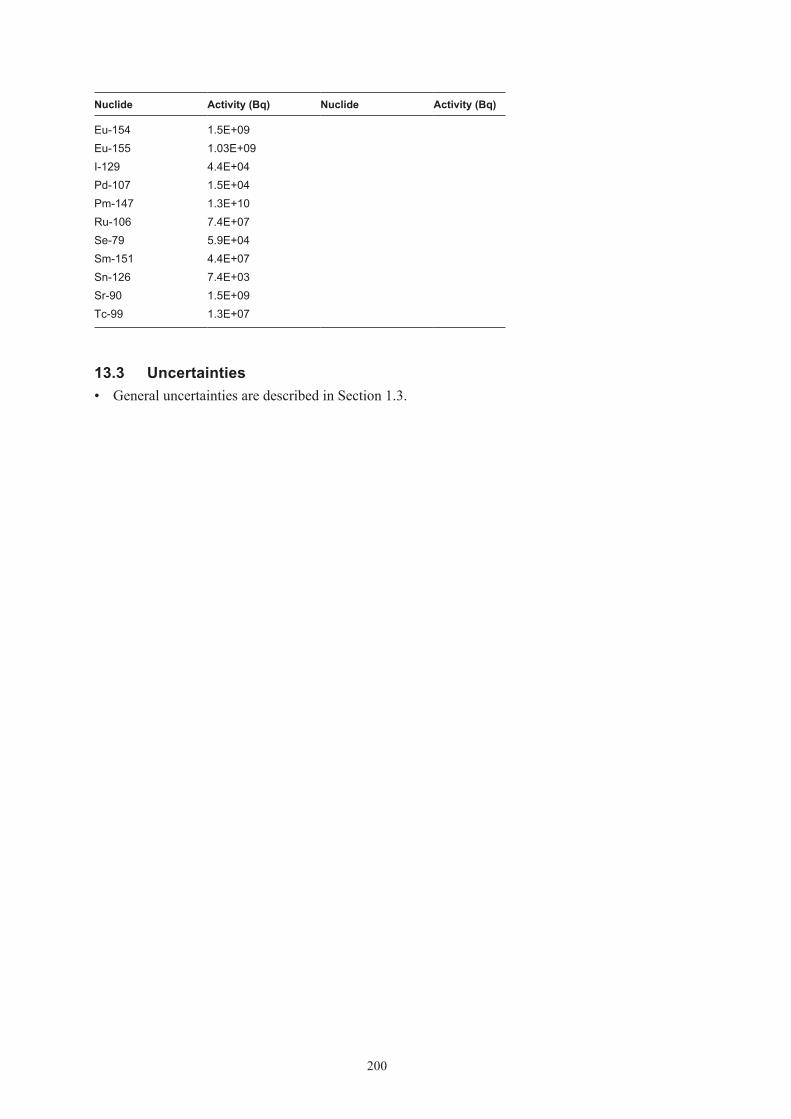
200
Nuclide Activity (Bq) Nuclide Activity (Bq)
Eu-154 1.5E+09Eu-155 1.03E+09I-129 4.4E+04Pd-107 1.5E+04Pm-147 1.3E+10Ru-106 7.4E+07Se-79 5.9E+04Sm-151 4.4E+07Sn-126 7.4E+03Sr-90 1.5E+09Tc-99 1.3E+07
13.3 Uncertainties• GeneraluncertaintiesaredescribedinSection1.3.

201
14 R.23
14.1 Waste type description14.1.1 Waste packageGeneralThe R.23 waste type consists of 1.73 m3 concrete or steel moulds with scrap metal and refuse in a concrete matrix. The raw waste material consists of mainly iron/steel, cellulose and other organics generated at the Ringhals nuclear power plant. The material is classified as intermedi-ate level waste. All data comes from /Ahlqvist 1993, Johansson 2000, Triumf 2007/.
Following restrictions are always applicable on this waste:
• ThegeneralrestrictionslistedinSection1.1.
PackagingThe steel mould has the dimension 1.2×1.2×1.2 m. The weight is 661 kg including lid and the total metal surface area of package is 23 m2. The wall of the package is 5 mm thick, the bottom is 6 mm thick. The mould also has two lids and some reinforcements. The variations between moulds are minimal. Total weight of package including waste is approximately 2,700 kg but differs between 2,100–4,900 kg.
The concrete mould is a cubic box made of reinforced concrete with the dimensions 1.2×1.2×1.2 m. The walls are 10 cm thick. The reinforcement is made of 12 mm steel bars with a total surface of 10 m2. The mould weighs approximately 1,600 kg. The variations between moulds are minimal. Total weight of package including waste is approximately 2,400 kg but differs between 2,200–4,100 kg.
In some special cases a concrete mould with 25 cm thick walls can be used.
The maximum allowed weight of a waste package is 5,000 kg.
Treatment and conditioningWaste from the power plant is sorted in compactible and non-compactible. Non-compactible is put directly in a mould and the mould is then filled with concrete. Compactible waste is put in the mould and compacted. A ‘middle-lid’ is placed in the mould to prevent re-expansion of the waste. This operation is repeated until the mould is full. Then the mould is filled with concrete.
Pouring concrete on top of the package makes a lid.
14.1.2 Materials – chemical compositionThe amounts of different materials in a R.23 mould are given in Table 14-1. The waste is fairly well defined and consists mainly of scrap metal and refuses as filters, wood, cloth, plastics and cables. The weight of the raw waste material is normally 770 kg waste per package but varies, see Table 14-1a and b.
The matrix is made of concrete. The brand used is of the standard Portland.

202
Table 14‑1a. Amounts of different material in waste type R.23 steel mould (per package).
Material Weight (kg)* Area (m2) Weight (%)
Cellulose 44 2.7Other organic material 100 6.2Iron/steel 100 5.1 6.2Aluminium 4 0.6 0.2Concrete** 1,356 84.5
* Variation of amounts of material is not available in referred documents.
** Including 0.13 kg water/kg concrete.
Table 14‑1b. Amounts of different material in waste type R.23 10‑cm concrete mould (per package).
Material Weight (kg)* Area (m2) Weight (%)
Cellulose 11 1.8Other organic material 25 4.0Iron/steel 25 1.3 4.0Aluminium 1 0.1 0.2Concrete** 565 90
* Variation of amounts of material is not available in referred documents.
** Including 0.13 kg water/kg concrete.
14.1.3 Radionuclide inventoryBefore the waste is transported from Ringhals to SFR 1 a measurement of gamma emitting nuclides is performed. Dominating nuclides are Co-60 and Cs-137. The amounts of these nuclides are between 0 and 6·1011 Bq for Co-60 and between 0 and 7·1010 Bq for Cs-137. Other nuclides than gamma emitting ones must be calculated according to Appendix B.
Dose rate limit for this package is 100 mSv/h but normally it is between 0.01–10 mSv/h on 1 metre. The surface contamination should not exceed 40 kBq/m2 for gamma and beta and 4 kBq/m2 for alpha emitting nuclides. The waste packages are usually free of contamination.
14.1.4 Waste productionThe waste type has been in production since 1960 and is still in production. Annual production is estimated to 5 packages per year, see Appendix A.
14.2 Reference waste type description14.2.1 Waste package and materialTable 14-2a and b shows the content of different materials and the steel surface areas of the packaging in the reference packages.
The assumed composition of the waste in the reference waste packages of R.23 is given in Table 14-3a and b.
The estimated volumes of the waste, the packaging materials and the void volume inside the package for a reference package are given in Table 14-4. The waste volume is estimated from the weights of the waste components in Table 14-3a and b and approximate densities of the different material. Average void is estimated to 5% in a package. Void and waste volume is specified in Table 14-4.
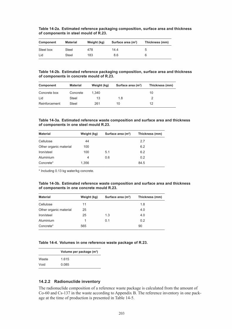
203
Table 14‑2a. Estimated reference packaging composition, surface area and thickness of components in steel mould of R.23.
Component Material Weight (kg) Surface area (m2) Thickness (mm)
Steel box Steel 478 14.4 5Lid Steel 183 8.6 6
Table 14‑2b. Estimated reference packaging composition, surface area and thickness of components in concrete mould of R.23.
Component Material Weight (kg) Surface area (m2) Thickness (mm)
Concrete box Concrete 1,340 10Lid Steel 13 1.8 2Reinforcement Steel 261 10 12
Table 14‑3a. Estimated reference waste composition and surface area and thickness of components in one steel mould R.23.
Material Weight (kg) Surface area (m2) Thickness (mm)
Cellulose 44 2.7Other organic material 100 6.2Iron/steel 100 5.1 6.2Aluminium 4 0.6 0.2Concrete* 1,356 84.5
* Including 0.13 kg water/kg concrete.
Table 14‑3b. Estimated reference waste composition and surface area and thickness of components in one concrete mould R.23.
Material Weight (kg) Surface area (m2) Thickness (mm)
Cellulose 11 1.8Other organic material 25 4.0Iron/steel 25 1.3 4.0Aluminium 1 0.1 0.2Concrete* 565 90
Table 14‑4. Volumes in one reference waste package of R.23.
Volume per package (m3)
Waste 1.615Void 0.085
14.2.2 Radionuclide inventoryThe radionuclide composition of a reference waste package is calculated from the amount of Co-60 and Cs-137 in the waste according to Appendix B. The reference inventory in one pack-age at the time of production is presented in Table 14-5.

204
Table 14‑5a. Radionuclide composition of a reference waste package of the type R.23 in concrete moulds.
Nuclide Activity (Bq) Nuclide Activity (Bq)
Correlated to Co-60 Correlated to PuCo-60 1.6E+10 Pu-239 7.4E+04Cl-36 9.9E+03 Pu-240 1.5E+05Ag-108m 9.9E+05 U-232 6.6E+00Ba-133 1.6E+05 U-234 2.2E+02Be-10 9.9E+00 U-235 4.4E+00C-14 4.9E+07 U-236 6.6E+01Fe-55 1.6E+10 U-238 8.8E+01H-3 1.6E+06 Np-237 8.8E+01Ho-166m 6.6E+04 Pu-238 5.8E+05Mo-93 1.6E+04 Pu-241 2.2E+07Nb-93m 1.6E+07 Pu-242 6.6E+02Nb-94 1.6E+05 Am-241 5.5E+05Ni-59 1.6E+07 Am-242m 2.2E+03Ni-63 1.3E+09 Am-243 6.6E+03Sb-125 1.7E+09 Cm-243 4.4E+03Zr-93 1.6E+04 Cm-244 1.5E+06
Cm-245 6.6E+01Correlated to Cs-137 Cm-246 1.8E+01Cs-137 6.1E+08Cd-113m 3.6E+05Cs-134 3.7E+08Cs-135 6.1E+03Eu-152 4.2E+04Eu-154 6.1E+07Eu-155 4.2E+07I-129 1.8E+03Pd-107 6.1E+02Pm-147 5.5E+08Ru-106 2.4E+08Se-79 2.4E+03Sm-151 1.8E+06Sn-126 3.0E+02Sr-90 6.1E+07Tc-99 5.5E+05
Table 14‑5b. Radionuclide composition of a reference waste package of the type R.23 in steel moulds.
Nuclide Activity (Bq) Nuclide Activity (Bq)
Correlated to Co-60 Correlated to PuCo-60 4.0E+10 Pu-239 1.8E+04Cl-36 2.4E+04 Pu-240 3.4E+05Ag-108m 2.4E+06 U-232 1.7E+01Ba-133 4.0E+05 U-234 5.5E+02Be-10 2.4E+01 U-235 1.1E+01

205
Nuclide Activity (Bq) Nuclide Activity (Bq)
C-14 1.2E+08 U-236 1.7E+02Fe-55 4.0E+10 U-238 2.2E+02H-3 4.0E+06 Np-237 2.2E+02Ho-166m 1.6E+05 Pu-238 1.4E+06Mo-93 4.0E+04 Pu-241 5.5E+07Nb-93m 4.0E+07 Pu-242 1.7E+03Nb-94 4.0E+05 Am-241 1.4E+06Ni-59 4.0E+07 Am-242m 5.5E+03Ni-63 3.2E+09 Am-243 1.7E+04Sb-125 4.0E+09 Cm-243 1.1E+04Zr-93 4.0E+04 Cm-244 3.8E+06
Cm-245 1.7E+02Correlated to Cs-137 Cm-246 4.4E+01Cs-137 3.0E+08Cd-113m 1.8E+05Cs-134 3.0E+08Cs-135 3.0E+03Eu-152 2.1E+04Eu-154 3.0E+07Eu-155 2.1E+07I-129 9.1E+02Pd-107 3.0E+02Pm-147 2.7E+08Ru-106 1.5E+06Se-79 1.2E+03Sm-151 9.1E+05Sn-126 1.5E+02Sr-90 3.0E+07Tc-99 2.7E+05
A reference waste package of the type R.23 has a surface dose rate of 100 mSv/h and no surface contamination.
14.3 Uncertainties• GeneraluncertaintiesaredescribedinSection1.3.
• AllfutureproductionofR.23isassumedtobeinsteelmoulds.Somepackagesmaybeoftheconcrete kind.

206
15 R.29
15.1 Waste type description15.1.1 Waste packageGeneralThe R.29 waste type consist of 1.73 m3 concrete moulds with evaporator concentrate in a concrete matrix. It is generated at Ringhals nuclear power plant. The material is classified as intermediate level waste. All data comes from /Einarsson 2006, Triumf 2007/.
Following restrictions are always applicable on this waste:
• ThegeneralrestrictionslistedinSection1.1.
PackagingThe concrete mould has the dimension 1.2×1.2×1.2 m. The weight is 1,600 kg including lid. The walls of the package are 10 cm thick. The mould weighs approximately 1,600 kg. The variations between moulds are minimal. Total weight of package including waste is approximately 4,000 kg.
The maximum allowed weight of a waste package is 5,000 kg.
Treatment and conditioningThe waste is first processed in an evaporator, put through a process that oxidises the organic matter, then it is dried further to a substance with a dry matter content of 10–20%. Then the waste is put into the concrete mould and later filled with concrete.
15.1.2 Materials – chemical compositionThe amounts of different materials in a R.29 mould are given in Table 15-1. The weight of the raw waste material is normally 700 kg waste per package but varies between 350 and 1,000 kg.
The matrix is made of concrete.
Table 15‑1. Amounts of different material in waste type R.29 (per package).
Material Weight (kg)* Area (m2) Weight (%)
Cement 3,200 79Evaporator concentrate 700 17Iron/steel 160 7.9 4
15.1.3 Radionuclide inventoryBefore the waste is transported from Ringhals to SFR 1 a measurement of gamma emitting nuclides is performed. Dominating nuclide is Co-60. Other nuclides than gamma emitting ones must be calculated according to Appendix B.
Dose rate limit for this package is 100 mSv/h. The surface contamination should not exceed 40 kBq/m2 for gamma and beta and 4 kBq/m2 for alpha emitting nuclides.
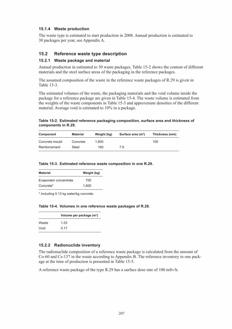
207
15.1.4 Waste productionThe waste type is estimated to start production in 2008. Annual production is estimated to 30 packages per year, see Appendix A.
15.2 Reference waste type description15.2.1 Waste package and materialAnnual production in estimated to 30 waste packages. Table 15-2 shows the content of different materials and the steel surface areas of the packaging in the reference packages.
The assumed composition of the waste in the reference waste packages of R.29 is given in Table 15-3.
The estimated volumes of the waste, the packaging materials and the void volume inside the package for a reference package are given in Table 15-4. The waste volume is estimated from the weights of the waste components in Table 15-3 and approximate densities of the different material. Average void is estimated to 10% in a package.
Table 15‑2. Estimated reference packaging composition, surface area and thickness of components in R.29.
Component Material Weight (kg) Surface area (m2) Thickness (mm)
Concrete mould Concrete 1,600 100Reinforcement Steel 160 7.9
Table 15‑3. Estimated reference waste composition in one R.29.
Material Weight (kg)
Evaporator concentrate 700Concrete* 1,600
* Including 0.13 kg water/kg concrete.
Table 15‑4. Volumes in one reference waste packages of R.29.
Volume per package (m3)
Waste 1.53Void 0.17
15.2.2 Radionuclide inventoryThe radionuclide composition of a reference waste package is calculated from the amount of Co-60 and Cs-137 in the waste according to Appendix B. The reference inventory in one pack-age at the time of production is presented in Table 15-5.
A reference waste package of the type R.29 has a surface dose rate of 100 mSv/h.

208
Table 15‑5. Radionuclide composition of a reference waste package of the type R.29.
Nuclide Activity (Bq) Nuclide Activity (Bq)
Correlated to Co-60 Correlated to PuCo-60 2.2E+08 Pu-239 2.0E+03Cl-36 1.3E+02 Pu-240 4.0E+03Ag-108m 1.3E+04 U-232 1.8E–01Ba-133 2.2E+03 U-234 6.0E+00Be-10 1.3E–01 U-235 1.2E–01C-14 6.6E+05 U-236 1.8E+00Fe-55 2.2E+08 U-238 2.4E+00H-3 2.2E+04 Np-237 2.4E+00Ho-166m 8.8E+02 Pu-238 2.4E+04Mo-93 2.2E+02 Pu-241 6.0E+05Nb-93m 2.2E+05 Pu-242 1.8E+01Nb-94 2.2E+03 Am-241 6.0E+03Ni-59 2.2E+05 Am-242m 6.0E+01Ni-63 1.8E+07 Am-243 1.8E+02Sb-125 2.2E+07 Cm-243 1.2E+02Zr-93 2.2E+02 Cm-244 1.8E+04
Cm-245 1.8E+00Correlated to Cs-137 Cm-246 4.8E–01Cs-137 2.7E+07Cd-113m 1.6E+04Cs-134 2.7E+07Cs-135 2.7E+02Eu-152 1.9E+03Eu-154 2.7E+06Eu-155 1.9E+06I-129 8.1E+01Pd-107 2.7E+01Pm-147 2.4E+07Ru-106 1.4E+05Se-79 1.1E+02Sm-151 8.1E+04Sn-126 1.4E+01Sr-90 2.7E+06Tc-99 2.4E+04
15.3 Uncertainties• GeneraluncertaintiesaredescribedinSection1.3.

209
16 S.09
16.1 Waste type description16.1.1 Waste packageGeneralThe S.09 waste type consists of a standard 200-litre drum containing sludges in a cement matrix. The raw waste material consists sludges generated at the Studsvik research centre. The material is classified as intermediate level waste. All data comes from /Chyssler 2000, Johansson 2000, Studsvik 2000/.
The physical properties and chemical conditions are well known. The following restrictions are always applicable:
• ThegeneralrestrictionslistedinSection1.1.
• Thecontentofcomplexingagentsshouldbewellknown.
PackagingThe steel drum is made of stainless steel with diameter 0.57 m and 0.84 m in height. The wall thickness is 1.5 mm. The drum weighs approximately 60 kg and surface area is approximately 5.1 m2. To facilitate the handling in SFR the drums are placed four by four on a steel plate with the dimension 1.2 m ·1.2 m and the thickness of 4 mm. The weight of the steel plate is 66 kg with surface area of 4.0 m2. The variations between packages are minimal. No major changes in design have been made since the start of production of this package.
The weight in total of a package including waste and is approximately 350 kg. The maximum allowed weight of a waste package is 500 kg.
Treatment and conditioningThe sludges containing radionuclides are mixed with concrete in a custom-made facility at the Studsvik site. Cement is added in the drum and then sludge and water is pumped into the drum.
When the waste is added the stirrer is started and the waste matrix is mixed. The matrix is then allowed to harden for one day. After measurements a steel lid is placed on top of the drum. The drums are placed on the steel plate when the drums are sent to SFR.
The void varies but is estimated to 0.01 m3 in a drum.
16.1.2 Materials – chemical compositionThe average amounts of different materials in an ‘typical package’ are given in Table 16-1. Waste matrix contains sludge (with dry weight 3–5%) from cleaning up system for Studsvik radioactive waste water treatment. Main compounds in the sludge is ferric hydroxide, cupper ferric cyanide, this waste could also contain some complexing agents originating form the laundry.
Most important from laundry is the organic chelating compounds EDTA and gluconic acid. The weight of the raw waste material is normally 5 kg sludge per package, see Table 16-1. The matrix is made of concrete. No cement additives are used.

210
Table 16‑1. Amounts of different material in waste type S.09 (per package).
Material Weight (kg)* Weight (%)
Sludge 5 1.8Concrete 280 98.2
* No data concerning variations is available.
16.1.3 Radionuclide inventoryBefore the waste is solidified a measurement of gamma emitting nuclides is performed. Dominating nuclides are Co-60 and Cs-137. The amounts of these nuclides are between 0 and 2·1010 Bq for Co-60 and between 0 and 4·109 Bq for Cs-137. Other nuclides than gamma emit-ting ones must be calculated according to Appendix B.
The dose rate limit for this package is 50 mSv/h. No estimation on variation of dose rates are available in referred documents. The surface contamination should not exceed 40 kBq/m2 for gamma and beta and 4 kBq/m2 for alpha emitting nuclides. The waste packages are usually free of contamination.
16.1.4 Waste productionAnnual production is estimated to 20 packages, see Appendix A.
16.2 Reference waste type description16.2.1 Waste package and materialTable 16-2 shows the content of different materials and the surface areas of the packaging in S.09 package from Studsvik. Since the steel plate and expansion box is shared between four drums ¼ of the plate and box is included in a package of S.09.
The assumed composition of the waste in a reference waste package of S.09 is given in Table 16-3.
Void and waste volume is specified in Table 16-4. Average void is estimated to 0.01 m3 in a steel drum.
Table 16‑2. Estimated reference packaging composition and surface area and thickness of components in each steel drum and one ¼ of a steel plate and expansion box of S.09.
Component Material Weight (kg) Surface area (m2) Thickness (mm)
Steel drum steel 60 5.1 1.5Steel plate steel 16.6 1.0 4
Table 16‑3. Estimated reference waste composition in one steel drum of S.09.
Material Weight (kg)
Sludge 5 Cement* 280
* Including water 0.4 kg/kg cement.

211
Table 16‑4. Volumes in one reference waste package of steel drums including ¼ steel plate and expansion box per drum of S.09.
Volume per package (m3)
Waste 0.2Void 0.01
16.2.2 Radionuclide inventoryThe radionuclide composition of a reference waste package is calculated from the amount of Co-60 and Cs-137 in the waste according to Appendix B. The reference inventory in one pack-age at the time of production is presented in Table 16-5.
A reference waste package of the type S.09 has a surface dose rate of 50 mSv/h and no surface contamination.
Table 16‑5. Radionuclide composition of a reference waste package of the type S.09.
Nuclide Activity (Bq) Nuclide Activity (Bq)
Correlated to Co-60 Correlated to PuCo-60 1.8E+08 Pu-239 1.1E+04Cl-36 6.0E+04 Pu-240 2.2E+04Ag-108m 1.1E+04 U-232 9.7E–01Ba-133 1.8E+03 U-234 3.2E+01Be-10 1.1E–01 U-235 6.5E–01C-14 1.8E+05 U-236 9.7E+00Fe-55 1.8E+08 U-238 1.3E+01H-3 1.8E+04 Np-237 1.3E+01Ho-166m 7.3E+03 Pu-238 1.3E+05Mo-93 9.1E+03 Pu-241 3.2E+06Nb-93m 1.8E+05 Pu-242 9.7E+01Nb-94 1.8E+03 Am-241 3.2E+04Ni-59 1.8E+05 Am-242m 3.2E+02Ni-63 3.6E+07 Am-243 9.7E+02Sb-125 1.8E+07 Cm-243 6.5E+02Zr-93 1.8E+03 Cm-244 9.7E+04
Cm-245 9.7E+00Correlated to Cs-137 Cm-246 2.6E+00Cs-137 6.0E+09Cd-113m 3.6E+06Cs-134 6.0E+09Cs-135 3.0E+04Eu-152 4.2E+05Eu-154 6.0E+08Eu-155 4.2E+08I-129 1.8E+03Pd-107 6.0E+03Pm-147 5.4E+09Ru-106 3.0E+07

212
Nuclide Activity (Bq) Nuclide Activity (Bq)
Se-79 2.4E+04Sm-151 1.8E+07Sn-126 3.0E+03Sr-90 6.0E+08Tc-99 3.0E+07
16.3 Uncertainties• GeneraluncertaintiesaredescribedinSection1.3.

213
17 S.23
17.1 Waste type description17.1.1 Waste packageGeneralThe S.23 waste type consists of 1.73 m3 concrete moulds with scrap metal and refuse in a concrete matrix. The raw waste material consists of mainly iron/steel, cellulose and other organ-ics generated at the Studsvik research site. The material is classified as intermediate level waste. All data comes from /Chyssler 1997, Johansson 2000, Triumf 2007/.
Following restrictions are always applicable on this waste:
• ThegeneralrestrictionslistedinSection1.1.
PackagingThe concrete mould is a cubic box made of reinforced concrete with the dimensions 1.2×1.2×1.2 m. The walls are 10 cm thick. The reinforcement is made of 12 mm steel bars with a total surface of 10 m2. The 10-cm mould weighs approximately 1,600 kg. The variations between moulds are minimal. Total weight of package including waste is approximately 3,500 kg but differs between 2,900–4,900 kg.
The maximum allowed weight of a waste package is 5,000 kg.
Treatment and conditioningWaste from the power plant is sorted in compactable and non-compactable. Non-compactable is put directly in a mould and the mould is then filled with concrete. Compactable waste is put in the mould and compacted. A ‘middle-lid’ is placed in the mould to prevent re-expansion of the waste. This operation is repeated until the mould is full. Then the mould is filled with concrete, which is allowed to harden. Pouring concrete on top of the package makes a lid.
17.1.2 Materials – chemical compositionThe amounts of different materials in a S.23 mould are given in Table 17-1. The waste is fairly well defined and consists mainly of scrap metal and refuses as filters, wood, cloth, plastics and cables. The weight of the raw waste material is normally 780 kg waste per package but varies, see Table 17-1.
The matrix is made of concrete. The brand used is Betokem EXM 4PA.
Table 17‑1. Amounts of different material in waste type S.23 10‑cm concrete mould (per package).
Material Weight (kg)* Area (m2) Weight (%)
Sludge 3.8 0.5Cellulose 29 3.4Iron/steel 113 5.8 13.2Aluminium 3.8 0.6 0.5Other inorganic material 139 16.3Concrete** 565 66.2
* Variation of amounts of material is not available in referred documents.
** Including 0.13 kg water/kg concrete.

214
17.1.3 Radionuclide inventoryBefore the waste is transported from Studsvik to SFR 1 a measurement of gamma emitting nuclides is performed. Dominating nuclides are Co-60 and Cs-137. Other nuclides than gamma emitting ones must be calculated according to Appendix B.
Dose rate limit for this package is 100 mSv/h, information on variations are not available. The surface contamination should not exceed 40 kBq/m2 for gamma and beta and 4 kBq/m2 for alpha emitting nuclides. The waste packages are usually free of contamination.
17.1.4 Waste productionAnnual production is estimated to 10 packages, see Appendix A.
17.2 Reference waste type description17.2.1 Waste package and materialTable 17-2 shows the content of different materials and the steel surface areas of the packaging in a reference package.
The assumed composition of the waste in a reference waste package of S.23 is given in Table 17-3.
The estimated volumes of the waste, the packaging materials and the void volume inside the package for a reference package are given in Table 17-4. The waste volume is estimated from the weights of the waste components in Table 17-3 and approximate densities of the different material. Average void is estimated to 5% in a package. Void and waste volume is specified in Table 17-4.
Table 17‑2. Estimated reference packaging composition, surface area and thickness of components in steel mould of S.23.
Component Material Weight (kg) Surface area (m2) Thickness (mm)
Concrete box Concrete 1,340 10Lid Steel 13 1.8 2Reinforcement Steel 261 10 12
Table 17‑3. Estimated reference waste composition and surface area and thickness of components in one S.23.
Material Weight (kg) Surface area (m2) Thickness (mm)
Sludge 3.8 0.5Cellulose 29 3.4Iron/steel 113 5.8 13.2Aluminium 3.8 0.6 0.5Other inorganic material 139 16.3Concrete* 565 66.2
* Including 0.13 kg water/kg concrete.

215
Table 17‑4. Volumes in one reference waste package of S.23.
Volume per package (m3)
Waste 0.95Void 0.05
17.2.2 Radionuclide inventoryThe radionuclide composition of a reference waste package is calculated from the amount of Co-60 and Cs-137 in the waste according to Appendix B. The reference inventory in one pack-age at the time of production is presented in Table 17-5. Inventory based on data for B.12, F.12 and R.12.
A reference waste package of the type S.23 has a surface dose rate of 100 mSv/h and no surface contamination.
Table 17‑5. Radionuclide composition of a reference waste package of the type S.23.
Nuclide Activity (Bq) Nuclide Activity (Bq)
Correlated to Co-60 Correlated to PuCo-60 1.7E+10 Pu-239 1.5E+06Cl-36 9.4E+03 Pu-240 3.1E+06Ag-108m 1.0E+06 U-232 1.4E+02Ba-133 1.7E+05 U-234 4.6E+03Be-10 1.0E+01 U-235 9.2E+01C-14 1.7E+07 U-236 1.4E+03Fe-55 1.7E+10 U-238 1.8E+03H-3 1.7E+06 Np-237 1.8E+03Ho-166m 6.8E+05 Pu-238 1.8E+07Mo-93 8.5E+05 Pu-241 4.6E+08Nb-93m 1.7E+07 Pu-242 1.4E+04Nb-94 1.7E+05 Am-241 4.6E+06Ni-59 1.7E+07 Am-242m 4.6E+04Ni-63 3.4E+09 Am-243 1.4E+05Sb-125 1.7E+09 Cm-243 9.2E+04Zr-93 1.7E+05 Cm-244 1.4E+07
Cm-245 1.4E+03Correlated to Cs-137 Cm-246 3.7E+02Cs-137 9.4E+08Cd-113m 5.6E+05Cs-134 9.4E+08Cs-135 4.7E+03Eu-152 6.6E+04Eu-154 9.4E+07Eu-155 6.6E+07I-129 2.8E+02Pd-107 9.4E+02Pm-147 8.5E+08

216
Nuclide Activity (Bq) Nuclide Activity (Bq)
Ru-106 4.7E+06Se-79 3.8E+03Sm-151 2.8E+06Sn-126 4.7E+02Sr-90 9.4E+07Tc-99 4.7E+06
17.3 Uncertainties• GeneraluncertaintiesaredescribedinSection1.3.

217
18 F.99:1
18.1 Waste type description18.1.1 Waste packageGeneralThe F.99:1 waste type consists of 1.73 m3 steel moulds containing steel drums with a rest slurry from oxidation tests conducted at Forsmark nuclear power plant. The material is classified as intermediate level waste. All data comes from /MAAS 6/94, Triumf 2007/.
Following restrictions are always applicable on this waste:
• ThegeneralrestrictionslistedinSection1.1.
PackagingThe steel mould has the dimension 1.2×1.2×1.2 m. The weight is 661 kg including lid and the total metal surface area of package is 23 m2. The wall of the package is 5 mm thick, the bottom is 6 mm thick.
The steel drums are made of stainless steel with diameter 0.595 m and 0.882 m in height. The thickness of the material is 1.2 mm. The drum weighs approximately 23 kg and the surface area is approximately 3 m2.
The maximum allowed weight of a waste package is 5,000 kg.
Treatment and conditioningThe slurry is mixed with cement in a custom made facility in the Forsmark NPP: After filling, the drums are topped with a small amount of cement. The void varies but is estimated to 0.02–0.03 m3 in a drum.
18.1.2 Materials – chemical compositionThe amounts of different materials in a F.99:1 mould are given in Table 18-1.
Table 18‑1. Amounts of different material in waste type F.99:1 (per package).
Material Weight (kg) Area (m2)
Other organic material 35Iron/steel 225 11
18.1.3 Radionuclide inventoryBefore the waste is transported from Forsmark to SFR 1 a measurement of gamma emitting nuclides is performed. Dominating nuclide is Co-60. Other nuclides than gamma emitting ones must be calculated according to Appendix B.
Dose rate limit for this package is 100 mSv/h. The surface contamination should not exceed 40 kBq/m2 for gamma and beta and 4 kBq/m2 for alpha emitting nuclides. The waste packages are usually free of contamination.

218
18.1.4 Waste productionThe waste type has been in production since 1987. No further production is foreseen, see Appendix A.
18.2 Reference waste type description18.2.1 Waste package and materialTable 18-2 shows the content of different materials and the steel surface areas of the packaging in the reference packages.
The estimated volumes of the waste, the packaging materials and the void volume inside the package for a reference package are given in Table 18-3. Average void is estimated to 10% in a package.
Table 18‑2. Estimated reference packaging composition, surface area and thickness of components in F.99:1.
Component Material Weight (kg) Surface area (m2) Thickness (mm)
Steel mould Stainless steel 400 10 5
Table 18‑3. Volumes in one reference waste packages of F.99:1.
Volume per package (m3)
Waste 1.615Void 0.085
18.2.2 Radionuclide inventoryThe radionuclide composition of a reference waste package is calculated from the amount of Co-60 and Cs-137 in the waste according to Appendix B. The reference inventory in one pack-age at the time of production is presented in Table 18-4.
A reference waste package of the type F.99:1 has a maximum surface dose rate of 100 mSv/h and no surface contamination.
Table 18‑4. Radionuclide composition of a reference waste package of the type F.99:1.
Nuclide Activity (Bq) Nuclide Activity (Bq)
Correlated to Co-60 Correlated to PuCo-60 7.0E+08 Pu-239 1.1E+03Cl-36 4.2E+02 Pu-240 2.3E+03Ag-108m 4.2E+04 U-232 1.0E–01Ba-133 7.0E+03 U-234 3.4E+00Be-10 4.2E–01 U-235 1.3E+01C-14 2.1E+06 U-236 1.0E+00Fe-55 7.0E+08 U-238 1.5E+01H-3 7.0E+04 Np-237 1.2E+02Ho-166m 2.8E+03 Pu-238 6.6E+03Mo-93 7.0E+02 Pu-241 3.4E+05

219
Nuclide Activity (Bq) Nuclide Activity (Bq)
Nb-93m 7.0E+05 Pu-242 1.0E+01Nb-94 7.0E+03 Am-241 1.9E+03Ni-59 7.0E+05 Am-242m 3.4E+01Ni-63 5.6E+07 Am-243 1.0E+02Sb-125 7.0E+07 Cm-243 3.5E+01Zr-93 7.0E+02 Cm-244 6.2E+03
Cm-245 1.0E+00Correlated to Cs-137 Cm-246 2.7E–01Cs-137 1.6E+08Cd-113m 9.9E+04Cs-134 1.0E+07Cs-135 1.6E+03Eu-152 1.2E+04Eu-154 1.6E+07Eu-155 1.2E+07I-129 4.9E+02Pd-107 1.6E+02Pm-147 1.5E+08Ru-106 8.2E+05Se-79 6.6E+02Sm-151 4.9E+05Sn-126 8.2E+01Sr-90 1.6E+07Tc-99 1.5E+05
18.3 Uncertainties• GeneraluncertaintiesaredescribedinSection1.3.

220
19 Other waste types
Since SFR 1 still is in operation there is always the possibility that new waste types are needed. It is not possible to define these types per se.
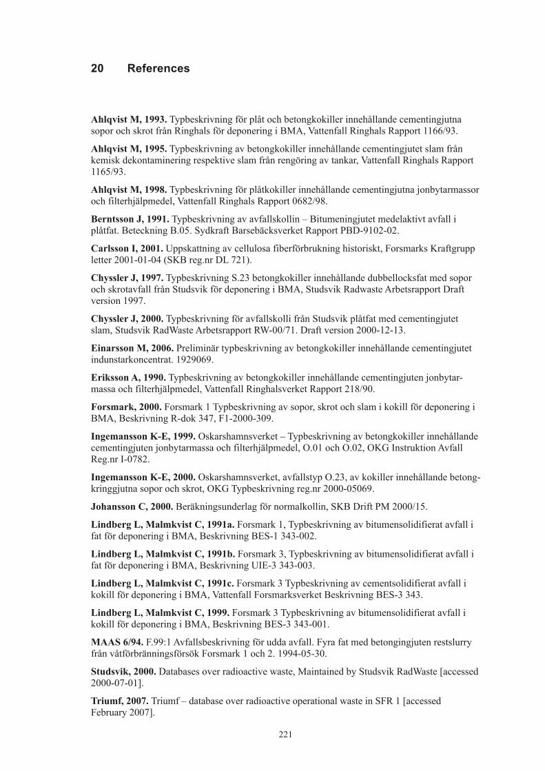
221
20 References
Ahlqvist M, 1993. Typbeskrivning för plåt och betongkokiller innehållande cementingjutna sopor och skrot från Ringhals för deponering i BMA, Vattenfall Ringhals Rapport 1166/93.
Ahlqvist M, 1995. Typbeskrivning av betongkokiller innehållande cementingjutet slam från kemisk dekontaminering respektive slam från rengöring av tankar, Vattenfall Ringhals Rapport 1165/93.
Ahlqvist M, 1998. Typbeskrivning för plåtkokiller innehållande cementingjutna jonbytarmassor och filterhjälpmedel, Vattenfall Ringhals Rapport 0682/98.
Berntsson J, 1991. Typbeskrivning av avfallskollin – Bitumeningjutet medelaktivt avfall i plåtfat. Beteckning B.05. Sydkraft Barsebäcksverket Rapport PBD-9102-02.
Carlsson I, 2001. Uppskattning av cellulosa fiberförbrukning historiskt, Forsmarks Kraftgrupp letter 2001-01-04 (SKB reg.nr DL 721).
Chyssler J, 1997. Typbeskrivning S.23 betongkokiller innehållande dubbellocksfat med sopor och skrotavfall från Studsvik för deponering i BMA, Studsvik Radwaste Arbetsrapport Draft version 1997.
Chyssler J, 2000. Typbeskrivning för avfallskolli från Studsvik plåtfat med cementingjutet slam, Studsvik RadWaste Arbetsrapport RW-00/71. Draft version 2000-12-13.
Einarsson M, 2006. Preliminär typbeskrivning av betongkokiller innehållande cementingjutet indunstarkoncentrat. 1929069.
Eriksson A, 1990. Typbeskrivning av betongkokiller innehållande cementingjuten jonbytar-massa och filterhjälpmedel, Vattenfall Ringhalsverket Rapport 218/90.
Forsmark, 2000. Forsmark 1 Typbeskrivning av sopor, skrot och slam i kokill för deponering i BMA, Beskrivning R-dok 347, F1-2000-309.
Ingemansson K-E, 1999. Oskarshamnsverket – Typbeskrivning av betongkokiller innehållande cementingjuten jonbytarmassa och filterhjälpmedel, O.01 och O.02, OKG Instruktion Avfall Reg.nr I-0782.
Ingemansson K-E, 2000. Oskarshamnsverket, avfallstyp O.23, av kokiller innehållande betong-kringgjutna sopor och skrot, OKG Typbeskrivning reg.nr 2000-05069.
Johansson C, 2000. Beräkningsunderlag för normalkollin, SKB Drift PM 2000/15.
Lindberg L, Malmkvist C, 1991a. Forsmark 1, Typbeskrivning av bitumensolidifierat avfall i fat för deponering i BMA, Beskrivning BES-1 343-002.
Lindberg L, Malmkvist C, 1991b. Forsmark 3, Typbeskrivning av bitumensolidifierat avfall i fat för deponering i BMA, Beskrivning UIE-3 343-003.
Lindberg L, Malmkvist C, 1991c. Forsmark 3 Typbeskrivning av cementsolidifierat avfall i kokill för deponering i BMA, Vattenfall Forsmarksverket Beskrivning BES-3 343.
Lindberg L, Malmkvist C, 1999. Forsmark 3 Typbeskrivning av bitumensolidifierat avfall i kokill för deponering i BMA, Beskrivning BES-3 343-001.
MAAS 6/94. F.99:1 Avfallsbeskrivning för udda avfall. Fyra fat med betongingjuten restslurry från våtförbränningsförsök Forsmark 1 och 2. 1994-05-30.
Studsvik, 2000. Databases over radioactive waste, Maintained by Studsvik RadWaste [accessed 2000-07-01].
Triumf, 2007. Triumf – database over radioactive operational waste in SFR 1 [accessed February 2007].

223
Appendix F
Waste types in the Silo
1 General 2261.1 Waste in the Silo 2261.2 Definitions 2271.3 Uncertainties 227
2 B.04 2282.1 Waste type description 228
2.1.1 Waste package 2282.1.2 Materials – chemical composition 2282.1.3 Radionuclide inventory 2282.1.4 Waste production 229
2.2 Reference waste type description 2292.2.1 Waste package and material 2292.5.2 Radionuclide inventory 229
2.3 Uncertainties 230
3 B.06 2313.1 Waste type description 231
3.1.1 Waste package 2313.1.2 Materials – chemical composition 2313.1.3 Radionuclide inventory 2323.1.4 Waste production 232
3.2 Reference waste type description 2323.2.1 Waste package and material 2323.2.2 Radionuclide inventory 233
3.3 Uncertainties 234
4 F.18 2354.1 Waste type description 235
4.1.1 Waste package 2354.1.2 Materials – chemical composition 2354.1.3 Radionuclide inventory 2364.1.4 Waste production 236
4.2 Reference waste type description 2364.2.1 Waste package and material 2364.2.2 Radionuclide inventory 237
4.3 Uncertainties 238
5 O.02 2395.1 Waste type description 239
5.1.1 Waste package 2395.1.2 Materials – chemical composition 2395.1.3 Radionuclide inventory 2405.1.4 Waste production 240
5.2 Reference waste type description 2405.2.1 Waste package and material 2405.2.2 Radionuclide inventory 241
5.3 Uncertainties 242

224
6 C.02 2436.1 Waste type description 243
6.1.1 Waste package 2436.1.2 Materials – chemical composition 2446.1.3 Radionuclide inventory 2446.1.4 Waste production 244
6.2 Reference waste type description 2446.2.1 Waste package and material 2446.2.2 Radionuclide inventory 245
6.3 Uncertainties 246
7 C.24 2477.1 Waste type description 247
7.1.1 Waste package 2477.1.2 Materials – chemical composition 2477.1.3 Radionuclide inventory 2487.1.4 Waste production 248
7.2 Reference waste type description 2487.2.1 Waste package and material 2487.2.2 Radionuclide inventory 249
7.3 Uncertainties 250
8 R.02 2518.1 Waste type description 251
8.1.1 Waste package 2518.1.2 Materials – chemical composition 2518.1.3 Radionuclide inventory 2528.1.4 Waste production 252
8.2 Reference waste type description 2528.2.1 Waste package and material 2528.2.2 Radionuclide inventory 253
8.3 Uncertainties 254
9 R.16 2559.1 Waste type description 255
9.1.1 Waste package 2559.1.2 Materials – chemical composition 2559.1.3 Radionuclide inventory 2569.1.4 Waste production 256
9.2 Reference waste type description 2569.2.1 Waste package and material 2569.2.2 Radionuclide inventory 257
9.3 Uncertainties 258
10 S.04 25910.1 Waste type description 259
10.1.1 Waste package 25910.1.2 Materials – chemical composition 25910.1.3 Radionuclide inventory 26010.1.4 Waste production 260
10.2 Reference waste type description 26010.2.1 Waste package and material 26010.2.2 Radionuclide inventory 261
10.3 Uncertainties 261

225
11 S.11 26211.1 Waste type description 262
11.1.1 Waste package 26211.1.2 Materials – chemical composition 26211.1.3 Radionuclide inventory 26311.1.4 Waste production 263
11.2 Reference waste type description 26311.2.1 Waste package and material 26311.2.2 Radionuclide inventory 264
11.3 Uncertainties 265
12 S.24 26612.1 Waste type description 266
12.1.1 Waste package 26612.1.2 Materials – chemical composition 26612.1.3 Radionuclide inventory 26612.1.4 Waste production 267
12.2 Reference waste type description 26712.2.1 Waste package and material 26712.2.2 Radionuclide inventory 268
12.3 Uncertainties 268
13 Other waste types 26913.1 Uncertainties 269
14 References 270
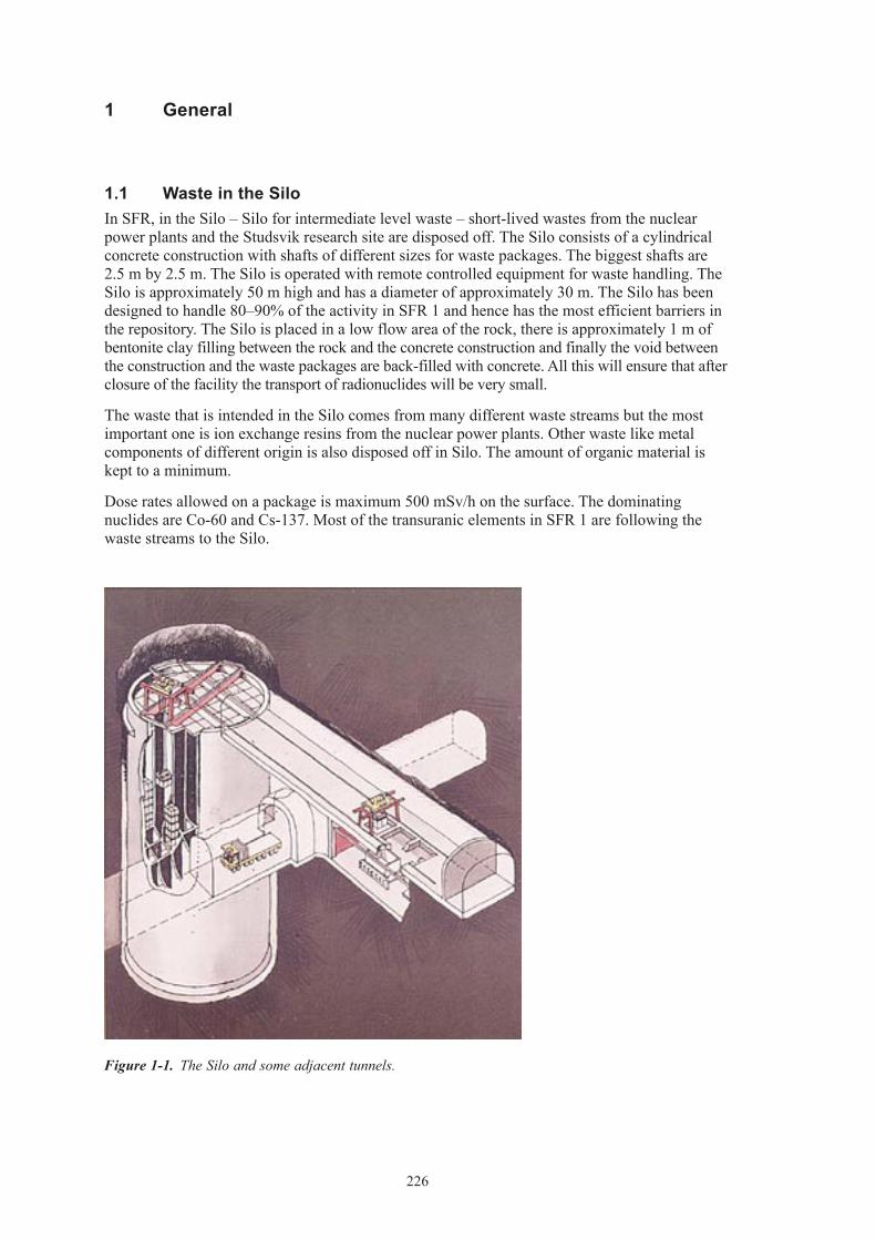
226
1 General
1.1 Waste in the SiloIn SFR, in the Silo – Silo for intermediate level waste – short-lived wastes from the nuclear power plants and the Studsvik research site are disposed off. The Silo consists of a cylindrical concrete construction with shafts of different sizes for waste packages. The biggest shafts are 2.5 m by 2.5 m. The Silo is operated with remote controlled equipment for waste handling. The Silo is approximately 50 m high and has a diameter of approximately 30 m. The Silo has been designed to handle 80–90% of the activity in SFR 1 and hence has the most efficient barriers in the repository. The Silo is placed in a low flow area of the rock, there is approximately 1 m of bentonite clay filling between the rock and the concrete construction and finally the void between the construction and the waste packages are back-filled with concrete. All this will ensure that after closure of the facility the transport of radionuclides will be very small.
The waste that is intended in the Silo comes from many different waste streams but the most important one is ion exchange resins from the nuclear power plants. Other waste like metal components of different origin is also disposed off in Silo. The amount of organic material is kept to a minimum.
Dose rates allowed on a package is maximum 500 mSv/h on the surface. The dominating nuclides are Co-60 and Cs-137. Most of the transuranic elements in SFR 1 are following the waste streams to the Silo.
Figure 1‑1. The Silo and some adjacent tunnels.

227
Other criteria for acceptance are:
• Construction,geometry,dimensionsandweightmustbesuitedtothehandlingsysteminSFR and the transportation system in general and in the Silo in particular. The strength of the packages must be sufficient to withstand normal and abnormal handling.
• Eachpackagemusthaveanindividualidentityandtheradionuclidecontentofgammaemitting nuclides shall be known.
• Surfacecontaminationshouldnotexceed40kBq/m2 for gamma and beta emitting nuclides and 4 kBq/m2 for alpha emitting nuclides.
• Theinternaldoseratesandintegrateddosemustnotaffectthebarrierpropertiesintherepository.
• Thechemicalandphysicalpropertiesandthestructureofthewasteshouldbeknown.
• Chemicalaggressiveorexplosivematerial,pressurisedgasandfreeliquidarenotallowed.
• Gasproductionfromthewastemustnotbetoobig.
• Thewasteshallhaveenoughresistancetowardscorrosionthattheintegrityofthepackageis kept until sealing of the repository.
• Burnablewastemustnotbesubjecttoself-ignition.
• Complexingagentsshouldbeavoided.
All waste in the Silo is normally packed in concrete or steel moulds, other packages that are used are steel drums.
1.2 Definitions
• Surfaceareaisdefinedastheareasubjecttoanaerobiccorrosionandgasproductionaftersealing of the repository.
1.3 Uncertainties
• Thepresentedwastetypesdescribethetypesthathavebeen,areinorcanbeforeseentobe produced in Sweden. New waste types may be present in the future.
• Almostalldataisbasedonliteraturevalues,smallerchangesmaynotbeenproperlydocumented.
• Allfutureproductionisbasedonarelativesimpleprognosismodel.Thismodel,describedin Appendix A, was chosen since the uncertainties about processes etc are large.
• Noregardhasbeentakentoimprovementsinprocessesetc.
• Areferencepackagehasbeenchosen.Actualpackagesmaydifferconsiderablyfromthisreference package, the uncertainty for the whole population of packages is judged to be smaller.
• Fortheradionuclideinventoryforeachwastepackagetheamountpresentediseitherbasedon the amount received from correlation factors or actual measurements when applicable. When there is a difference between different sub types of waste packages within one waste type the inventory presented in this appendix is the most conservative one.
• Voidpresentedinthisreportisbasedonbestestimates;theestimatescanbequitecrude.
• Tc-99iscorrelatedagainstbothCo-60andCs-137whenquantifyingtheinventories,according to Appendix B. In the tables “Radionuclide composition of a reference waste package” however Tc-99 is presented as only correlated towards Cs-137.

228
2 B.04
2.1 Waste type description2.1.1 Waste packageGeneralThe B.04 waste type consists of a standard 200-litre drum containing ion exchange resins in a cement matrix. The raw waste material consists of ion exchange resins generated at the Barsebäck nuclear power plant. The material is classified as intermediate level waste. All data comes from /Jönsson 2006, Johansson 2000, Triumf 2007/.
The physical properties and chemical conditions are well known. The following restrictions are always applicable:
• ThegeneralrestrictionslistedinSection1.1.
• Sincethepackagecontainsburnablesubstancestherestrictionsregardingself-ignitionetcare of special importance.
PackagingThe steel drum is made of stainless steel with diameter 0.590 m and 0.880 m in height. The thickness of the material is 1.2 mm. The drum weighs approximately 21 kg and the surface area is approximately 3 m2. The weight in total of a package including waste is approximately 375 kg. Maximum allowed weight of a waste package is 500 kg.
Treatment and conditioningThe ion exchange resin is mixed with cement in a custom made facility in the Barsebäck NPP. After filling, a steel lid is placed on the drum. The void is approximately 10%.
2.1.2 Materials – chemical compositionThe amounts of different materials in a B.04 are given in Table 2-1.
The waste is well defined and consists of ion exchange resins with radionuclides from cleaning systems (system 331, 352, 482 and 324). The systems contains both bead and power resins. The weight of the raw waste material is normally 33 kg ion exchange resin per package but varies.
Table 2‑1. Amounts of different material in waste type B.04 (per package).
Material Weight (kg) Weight (%)
Ion-exchange resin 33 9Iron/steel 40 11Cement 302 80
2.1.3 Radionuclide inventoryBefore the waste is transported from Barsebäck NPP to SFR 1 a measurement of gamma emitting nuclides is performed. Dominating nuclides are Co-60 and Cs-137. Other nuclides than gamma emitting ones must be calculated according to Appendix B.

229
The dose rate limit for this package is 500 mSv/h. The surface contamination should not exceed 40 kBq/m2 for gamma and beta and 4 kBq/m2 for alpha emitting nuclides. The waste packages are usually free of contamination.
2.1.4 Waste productionNo further production is foreseen, see Appendix A.
2.2 Reference waste type description2.2.1 Waste package and materialTable 2-2 shows the content of different materials and the surface areas of the packaging in B.04 package from Barsebäck.
The assumed composition of the waste in a reference waste package of B.04 is given in Table 2-3.
Void and waste volume is specified in Table 2-4.
Average void is estimated to 10% in a steel drum.
Table 2‑2. Estimated reference packaging composition and surface area and thickness of components in each steel drum of B.04.
Component Material Weight (kg) Surface area (m2) Thickness (mm)
Steel drum Stainless steel 21 3 1.2Stirrer Stainless steel 10
Table 2‑3. Estimated reference waste composition in one steel drum of B.04.
Material Weight (kg)
Ion-exchange resin 33
Table 2‑4. Volumes in one reference waste packages of B.04.
Volume one package (m3)
Waste 0.19Void 0.02
2.5.2 Radionuclide inventoryThe radionuclide composition of a reference waste package is calculated from the amount of Co-60 and Cs-137 in the waste according to Appendix B. The reference inventory in one pack-age at the time of production is presented in Table 2-5.
A reference waste package of the type B.04 has a surface dose rate of 100 mSv/h and no surface contamination.

230
Table 2‑5. Radionuclide composition of a reference waste package of the type B.04.
Nuclide Activity (Bq) Nuclide Activity (Bq)
Correlated to Co-60 Correlated to PuCo-60 2.0E+10 Pu-239 1.7E+04Cl-36 4.1E+04 Pu-240 1.7E+04Ag-108m 1.2E+06 U-232 5.0E–01Ba-133 2.0E+05 U-234 1.7E+01Be-10 1.2E+01 U-235 3.3E–01C-14 2.0E+07 U-236 5.0E+00Fe-55 2.0E+10 U-238 6.6E+00H-3 2.0E+06 Np-237 6.6E+00Ho-166m 7.9E+05 Pu-238 6.6E+04Mo-93 9.9E+05 Pu-241 1.7E+06Nb-93m 2.0E+07 Pu-242 5.0E+01Nb-94 2.0E+05 Am-241 1.7E+04Ni-59 2.0E+07 Am-242m 1.7E+02Ni-63 3.9E+09 Am-243 5.0E+02Sb-125 2.0E+09 Cm-243 3.3E+02Zr-93 2.0E+05 Cm-244 5.0E+04
Cm-245 5.0E+00Correlated to Cs-137 Cm-246 1.3E+00Cs-137 4.1E+09Cd-113m 2.5E+05Cs-134 4.1E+09Cs-135 2.1E+04Eu-152 2.9E+05Eu-154 4.1E+08Eu-155 2.9E+08I-129 1.2E+03Pd-107 4.1E+03Pm-147 3.7E+09Ru-106 2.1E+07Se-79 1.7E+04Sm-151 1.2E+07Sn-126 2.1E+03Sr-90 4.1E+08Tc-99 2.1E+07
2.3 Uncertainties• GeneraluncertaintiesaredescribedinSection1.3.

231
3 B.06
3.1 Waste type description3.1.1 Waste packageGeneralThe B.06 waste type consists of a standard 200-litre drum containing ion exchange resins in a bitumen matrix. The raw waste material consists of ion exchange resins and sludges generated at the Barsebäck nuclear power plant. The material is classified as intermediate level waste. All data comes from /Roth 1996, Johansson 2000, Triumf 2007/.
The physical properties and chemical conditions are well known. The following restrictions are always applicable:
• ThegeneralrestrictionslistedinSection1.1.
• Sincethepackagecontainsburnablesubstancestherestrictionsregardingself-ignitionetcare of special importance.
PackagingThe steel drum is made of stainless steel with diameter 0.595 m and 0.882 m in height. The thickness of the material is 1.2 mm. The drum weighs approximately 23 kg and the surface area is approximately 3 m2. To facilitate the handling in SFR the drums are placed four by four on a steel plate with the dimension 1.2×1.2 m and the thickness of 0.004 m. Between the four drums a expansion box is placed to provide expansion volume in case of swelling of the bitumen matrix. The box is made of steel and has a weight of 20 kg, the walls are 6 mm thick and the whole box has a surface area of 0.8 m2. The weight of the steel plate is 49 kg with surface area of 2.9 m2. The variations between packages are minimal. No major changes in design have been made since the start of production of this package except that since 1985 the drums are made of stainless steel. The weight in total of a package including waste and is approximately 200 kg. The maximum allowed weight of a waste package is 500 kg.
Treatment and conditioningThe ion exchange resin containing metal hydroxides and other substances are mixed with bitumen in a custom made facility in the Barsebäck NPP. The flow in the bitumenisation process is measured with electrical conductivity. A small amount of Na2SO4 is mixed with the product to give correct measurements of the conductivity. Emulgator is added in order to make the product more homogene. After filling, a steel lid is placed upon the drum. The drums are placed on the steel plate when they are sent to SFR.
The void varies but is estimated to 0.03 m3 in a drum (not including expansion box).
3.1.2 Materials – chemical compositionThe amounts of different materials in a B.06 drum are given in Table 3-1. The waste matrix con-tains metal hydroxides from the clean-up system for the reactor and evaporation residues from back flush water from the fuel storage pools. The weight of the raw waste material is normally 50 kg ion exchange resin per package but the weight varies, see Table 3-1.

232
The matrix is made of bitumen. The specific brand of bitumen has changed during the many years of production of this waste type but it is always of the distilled sort. The brands used are Mexphalate until 1982, Nynäs industrial bitumen IB 45 between 1983–1995 and Nynäs industrial bitumen IB 55 used from 1995. The amounts of added chemicals are: Na2SO4 0.2–0.5 kg/drum Emulgator 0.4–1.1 kg/drum
Table 3‑1. Amounts of different material in waste type B.06 (per package).
Material Weight (kg) Weight (%)
Ion-exchange resin 30–55 16–43Bitumen 129–155 57–84
3.1.3 Radionuclide inventoryBefore the waste is transported from Barsebäck NPP to SFR 1 a measurement of gamma emit-ting nuclides is performed. Dominating nuclides are Co-60 and Cs-137. The amounts of these nuclides are between 0 and 1.1·1011 Bq for Co-60 and between 0 and 2.7·1011 Bq for Cs-137. Other nuclides than gamma emitting ones must be calculated according to Appendix B.
The dose rate limit for this package is 500 mSv/h. Normal dose rate at 1 m is between 0–10 mSv/h. The surface contamination should not exceed 40 kBq/m2 for gamma and beta and 4 kBq/m2 for alpha emitting nuclides. The waste packages are usually free of contamination.
3.1.4 Waste productionThe waste type was in production from 1985. No further production is foreseen, see Appendix A.
3.2 Reference waste type description3.2.1 Waste package and materialTable 3-2 shows the content of different materials and the surface areas of the packaging in B.06 package from Barsebäck. Since the steel plate and expansion box is shared between four drums ¼ of the plate and box is included in a package of B.06.
The assumed composition of the waste in a reference waste package of B.06 is given in Table 3-3.
Void and waste volume is specified in Table 3-4.
Average void is estimated to 0.03 m3 in a steel drum.
Table 3‑2. Estimated reference packaging composition and surface area and thickness of components in each steel drum and one ¼ of a steel plate and expansion box of B.06.
Component Material Weight (kg) Surface area (m2) Thickness (mm)
Steel drum Stainless steel 23 3 1.2Steel plate Carbon steel 12.25 0.7 4Expansion box Carbon steel 5 0.2 6

233
Table 3‑3. Estimated reference waste composition in one steel drum of B.06.
Material Weight (kg)
Ion-exchange resin 50 Bitumen 150 Chemicals(Na-sulphate) 0.5
Table 3‑4. Volumes in one reference waste packages of steel drums including ¼ steel plate and expansion box per drum of B.06.
Volume one package (m3)
Waste 0.2Void 0.03
3.2.2 Radionuclide inventoryThe radionuclide composition of a reference waste package is calculated from the amount of Co-60 and Cs-137 in the waste according to Appendix B. The reference inventory in one pack-age at the time of production is presented in Table 3-5.
A reference waste package of the type B.06 has a surface dose rate of 100 mSv/h and no surface contamination.
Table 3‑5. Radionuclide composition of a reference waste package of the type B.06.
Nuclide Activity (Bq) Nuclide Activity (Bq)
Correlated to Co-60 Correlated to PuCo-60 1.9E+10 Pu-239 9.9E+03Cl-36 1.2E+04 Pu-240 2.0E+04Ag-108m 1.2E+06 U-232 8.9E–01Ba-133 1.9E+05 U-234 3.0E+01Be-10 1.2E+01 U-235 9.6E+02C-14 5.8E+07 U-236 8.3E+02Fe-55 1.9E+10 U-238 7.1E+02H-3 1.9E+06 Np-237 4.9E+03Ho-166m 7.7E+04 Pu-238 3.1E+04Mo-93 1.9E+04 Pu-241 3.0E+06Nb-93m 1.9E+07 Pu-242 8.9E+01Nb-94 1.9E+05 Am-241 2.3E+04Ni-59 1.9E+07 Am-242m 3.0E+02Ni-63 1.5E+09 Am-243 8.9E+02Sb-125 1.3E+09 Cm-243 6.0E+02Zr-93 1.9E+04 Cm-244 1.8E+04
Cm-245 8.9E+00Correlated to Cs-137 Cm-246 2.4E+00Cs-137 3.8E+09Cd-113m 2.3E+06Cs-134 3.3E+08Cs-135 3.8E+04Eu-152 2.7E+05

234
Nuclide Activity (Bq) Nuclide Activity (Bq)
Eu-154 3.8E+08Eu-155 2.7E+08I-129 1.2E+04Pd-107 3.8E+03Pm-147 3.4E+09Ru-106 1.9E+07Se-79 1.5E+04Sm-151 1.2E+07Sn-126 1.9E+03Sr-90 3.8E+08Tc-99 3.4E+06
3.3 Uncertainties• GeneraluncertaintiesaredescribedinSection1.3.
• TheproductionoftypeB.06wascloseddownintheendof2000.

235
4 F.18
4.1 Waste type description4.1.1 Waste packageGeneralThe F.18 waste type consists of 1.73 m3 steel moulds containing ion-exchange resins in a bitu-men matrix. The raw waste material consists of ion exchange resins generated at the Forsmark nuclear power plant. The material is classified as intermediate level waste. All data comes from /Jansson 1995, Johansson 2000, Triumf 2007/.
Following restrictions are always applicable on this waste:
• ThegeneralrestrictionslistedinSection1.1.
• Sincethepackagecontainsburnablesubstancestherestrictionsregardingself-ignitionetcare of special importance.
PackagingThe mould is a cubic box made of steel with the dimensions 1.2×1.2×1.2 m. The wall is 5 mm thick, the bottom is 6 mm thick. The mould weighs approximately 400 kg and the surface area is approximately 10 m2. The variations between moulds are minimal. No major change in design has been made since the start of production of this package.
The weight in total of a package including waste and is approximately 1,960 kg but differs between 1,860–2,260 kg. The maximum allowed weight of a waste package is 5,000 kg.
Treatment and conditioningThe ion-exchange resins are dried in 150°C in a conical dryer and are then homogenised with bitumen in a conical mixer. The mixed waste is then poured in a steel mould. Each batch is maximum 500 litres. The mix is then allowed to cool for at least 17 h before a thin layer (~1 cm) of pure bitumen is poured upon the waste matrix. The waste package is thereafter lidded with a steel lid.
The void varies but is estimated to 10% in a package.
4.1.2 Materials – chemical compositionThe amounts of different materials in a F.18 mould are given in Table 4-1. The waste is well defined and consists of ion exchange resins with radionuclides from system 324 and 331. The weight of the raw waste material is normally 600 kg ion exchange resin per package but varies, see Table 4-1.
The matrix is made of bitumen. The specific brand of bitumen has changed during the years of production of this waste type but it is always the distilled sort. The brands used are IB 45 Nynäs industrial bitumen used until 1994 and IB 55 Nynäs industrial bitumen from 1995.
No variation of material is identified in references.

236
Table 4‑1. Amounts of different material in waste type F.18 (per package).
Material Weight (kg) Weight (%)
Ion-exchange resin 600 38Bitumen 960 62
4.1.3 Radionuclide inventoryBefore the waste is transported from Forsmark NPP to SFR 1 a measurement of gamma emitting nuclides is performed. Dominating nuclides are Co-60 and Cs-137. The amounts of these nuclides are between 0 and 2.5·1012 Bq for Co-60 and between 0 and 1.9·1011 Bq for Cs-137. Other nuclides than gamma emitting ones must be calculated according to Appendix B.
The dose rate limit for this package is 500 mSv/h on the surface. Normal dose rate at 1 m is approximately 30 mSv/h; normal interval for dose rate at 1 m is between 5–80 mSv/h. The surface contamination should not exceed 40 kBq/m2 for gamma and beta and 4 kBq/m2 for alpha emitting nuclides on the package. The waste packages are usually free of contamination.
4.1.4 Waste productionThe waste type has been in production since 1991 and is still in production. The annual produc-tion is estimated to20 packages per year, see Appendix A.
4.2 Reference waste type description4.2.1 Waste package and materialTable 4-2 shows the content of different materials and the steel surface areas of the packaging in a reference package.
The assumed composition of the waste in a reference waste package of F.18 is given in Table 4-3.
Average void is estimated 10% in a steel mould. Void and waste volume is specified in Table 4-4.
Table 4‑2. Estimated reference packaging composition and surface area and thickness of components in steel mould of F.18.
Component Material Weight (kg) Surface area (m2) Thickness (mm)
Steel mould steel 400 10 5
Table 4‑3. Estimated reference waste composition and surface area and thickness of components in one of F.18.
Material Weight (kg)
Ion-exchange resin 600 Bitumen 960
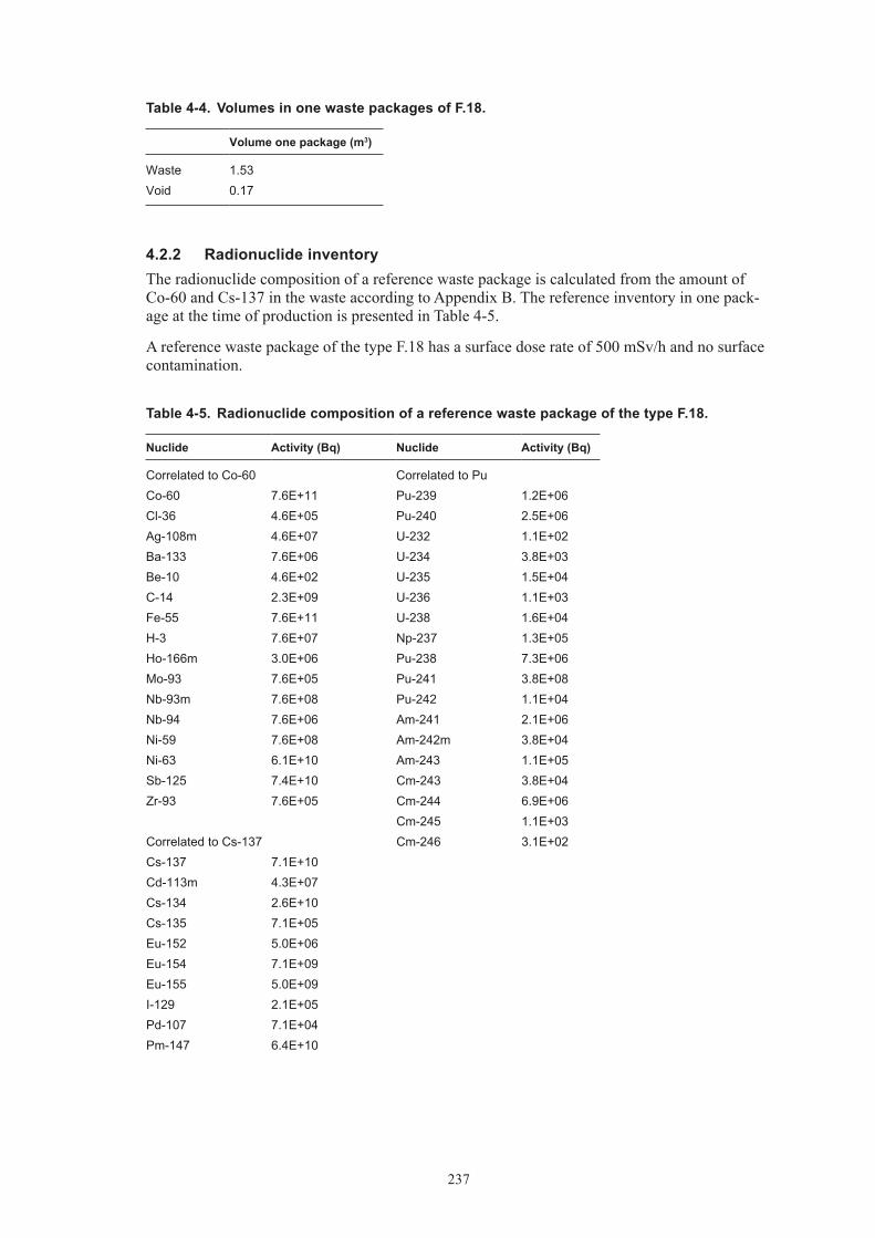
237
Table 4‑4. Volumes in one waste packages of F.18.
Volume one package (m3)
Waste 1.53Void 0.17
4.2.2 Radionuclide inventoryThe radionuclide composition of a reference waste package is calculated from the amount of Co-60 and Cs-137 in the waste according to Appendix B. The reference inventory in one pack-age at the time of production is presented in Table 4-5.
A reference waste package of the type F.18 has a surface dose rate of 500 mSv/h and no surface contamination.
Table 4‑5. Radionuclide composition of a reference waste package of the type F.18.
Nuclide Activity (Bq) Nuclide Activity (Bq)
Correlated to Co-60 Correlated to PuCo-60 7.6E+11 Pu-239 1.2E+06Cl-36 4.6E+05 Pu-240 2.5E+06Ag-108m 4.6E+07 U-232 1.1E+02Ba-133 7.6E+06 U-234 3.8E+03Be-10 4.6E+02 U-235 1.5E+04C-14 2.3E+09 U-236 1.1E+03Fe-55 7.6E+11 U-238 1.6E+04H-3 7.6E+07 Np-237 1.3E+05Ho-166m 3.0E+06 Pu-238 7.3E+06Mo-93 7.6E+05 Pu-241 3.8E+08Nb-93m 7.6E+08 Pu-242 1.1E+04Nb-94 7.6E+06 Am-241 2.1E+06Ni-59 7.6E+08 Am-242m 3.8E+04Ni-63 6.1E+10 Am-243 1.1E+05Sb-125 7.4E+10 Cm-243 3.8E+04Zr-93 7.6E+05 Cm-244 6.9E+06
Cm-245 1.1E+03Correlated to Cs-137 Cm-246 3.1E+02Cs-137 7.1E+10Cd-113m 4.3E+07Cs-134 2.6E+10Cs-135 7.1E+05Eu-152 5.0E+06Eu-154 7.1E+09Eu-155 5.0E+09I-129 2.1E+05Pd-107 7.1E+04Pm-147 6.4E+10

238
Nuclide Activity (Bq) Nuclide Activity (Bq)
Ru-106 3.6E+08Se-79 2.9E+05Sm-151 2.1E+08Sn-126 3.6E+04Sr-90 7.1E+09Tc-99 6.4E+07
4.3 Uncertainties• GeneraluncertaintiesaredescribedinSection1.3.

239
5 O.02
5.1 Waste type description5.1.1 Waste packageGeneralThe O.02 waste type consists of 1.73 m3 concrete moulds containing ion-exchange resins and inert filter-aid in a concrete matrix. The raw waste material consists of ion exchange resins and filter aids generated at the Oskarshamn nuclear power plant. The material is classified as inter-mediate level waste. All data comes from /Ingemansson 1999, Johansson 2000, Triumf 2007/.
Following restrictions are always applicable on this waste:
• ThegeneralrestrictionslistedinSection1.1.
PackagingThe mould is a cubic box made of reinforced concrete with the dimensions 1.2×1.2×1.2 m. The walls are normally 10 cm thick but can in some exceptional cases be 25 cm thick. The rein-forcement is made of 12 mm steel bars with a total surface of 10 m2. The 10-cm mould weighs approximately 1,600 kg and the 25-cm one weighs about 3,200 kg. A stirrer made of carbon steel is included in the waste package. It weighs 16 kg and has an estimated surface of 1 m2. To avoid cracking of the mould, due to expansion of the concrete matrix, a lining of compactable material (polyethene) is put inside of the mould, the lining has a thickness of 20 mm and a total weight of 10 kg. Lining is only placed in the 10-cm mould. The variations between moulds are minimal.
Some changes in the design have been made since the start of production of this package. 1975–78 the reinforcement was gradually improved and in 1981 a new design of reinforcement was introduced. In 1979 the moulds was fitted with a expansion cassette of polyurethane and wood, this was used until 1988 when the polyethene cassette was introduced. In 1986 a new brand of concrete to make the lid was introduced, instead of Sabema A, the Betokem EXM-4 was used. Today no chemical cement additives are used, earlier Silix GP was used.
The weight of a package including waste is approximately 3,200 kg but differs between 3,300–3,600 kg. The maximum allowed weight of a waste package is 5,000 kg.
Treatment and conditioningThe waste, used ion-exchange resins, is pumped into the mould and cement is added. If needed, water is added. When the cement is added the stirrer is started and the waste matrix is mixed for 30 minutes. The matrix is then allowed to harden for two days. Pouring concrete on top of the matrix then makes a lid. The lid is at least 10 cm thick. The concrete is allowed 24 hours to harden before the waste is transported to intermediate storage. The waste, used ion-exchange resins, is pumped into the mould and cement is added. If needed, water is added. When the cement is added the stirrer is started and the waste matrix is mixed for 30 minutes. The matrix is then allowed to harden for two days. Pouring concrete on top of the matrix then makes a lid. The concrete is allowed 24 hours to harden before the waste is transported to intermediate storage. The lid is at least 10 cm thick.
5.1.2 Materials – chemical compositionThe amounts of different materials in a O.02 mould are given in Table 5-1. The waste is well defined and consists of ion exchange resins and filter-aid with radionuclides from systems for cleaning reactor water (system 331), treatment of liquid waste (system 342), decontamination

240
(system 347) and cleaning of fuel ponds (system 324). Systems 331, 347 and 342 uses bead resin, system 342 uses powder resin. The weight of the raw waste material is normally 130 kg ion exchange resin per package but varies, see Table 5-1.
The matrix is made of cement. The specific brand of cement has changed during the years of production of this waste type. The brands used are: Sabema A-bruk 1970–1986, LH cement 1970–1981, Massiv cement 1981–1986, Anläggningscement 1986–1999, Höghållfasthetscement from 1999–, Betokem EXM used from 1986–.
Table 5‑1. Amounts of different material in waste type O.02 (per package).
Material Weight (kg) Weight (%)
Ion-exchange resin 90–150 5.7–10.0Cement* 1,350–1,500 90.0–94.3
* Including water 0.4 kg/kg cement.
5.1.3 Radionuclide inventoryBefore the waste is transported from Oskarshamn NPP to SFR 1 a measurement of gamma emit-ting nuclides is performed. Dominating nuclides are Co-60 and Cs-137. The amounts of these nuclides are between 0 and 9.4·1011 Bq for Co-60 and between 0 and 7.9·1012 Bq for Cs-137. Other nuclides than gamma emitting ones must be calculated according to Appendix B.
The dose rate limit for this package is 30 mSv/h on the surface. Normal dose rate at 1 m is 2 mSv/h but varies between 0–10 mSv/h. The contamination on surface should not exceed 40 kBq/m2 for gamma and beta and 4 kBq/m2 for alpha emitting nuclides on the package. The waste packages are usually free of contamination.
5.1.4 Waste productionThe waste type has been in production since 1970 and is still in production. The annual produc-tion is estimated to 40 packages per year, see Appendix A.
5.2 Reference waste type description5.2.1 Waste package and materialTable 5-2 shows the content of different materials and the steel surface areas of the packaging in a reference package.
The assumed composition of the waste in a reference waste package of O.02 is given in Table 5-3.
The estimated volumes of the waste, the packaging materials and the void volume inside the package for a reference package are given in Table 5-4. The waste volume is estimated from the weights of the waste components in Table 5-3 and approximate densities of the different material. Average void is estimated to 15% in a package. Void and waste volume is specified in Table 5-4.

241
Table 5‑2. Estimated reference packaging composition and surface area and thickness of components in concrete mould of O.02.
Component Material Weight (kg) Surface area (m2) Thickness (mm)
Concrete mould Concrete 1,340 100Reinforcement Steel 261 10 12Steel lid Steel 13 1.8 2Stirrer Steel 16 1 5Other organics Polyethene 10
Table 5‑3. Estimated reference waste composition and surface area and thickness of components in one of O.02.
Material Weight (kg)
Ion-exchange resin 130Cement* 1,540
* Including water 0.4 kg/kg cement.
Table 5‑4. Volumes in one waste packages of O.02.
Volume one package (m3)
Waste 0.85Void 0.15
5.2.2 Radionuclide inventoryThe radionuclide composition of a reference waste package is calculated from the amount of Co-60 and Cs-137 in the waste according to Appendix B. The reference inventory in one pack-age at the time of production is presented in Table 5-5.
A reference waste package of the type O.02 has a maximum surface dose rate of 300 mSv/h and no surface contamination.
Table 5‑5. Radionuclide composition of a reference waste package of the type O.02.
Nuclide Activity (Bq) Nuclide Activity (Bq)
Correlated to Co-60 Correlated to PuCo-60 1.1E+11 Pu-239 4.4E+05Cl-36 6.3E+04 Pu-240 8.7E+05Ag-108m 6.3E+06 U-232 3.9E+01Ba-133 1.1E+06 U-234 1.3E+03Be-10 6.3E+01 U-235 2.2E+01C-14 3.2E+08 U-236 9.1E+02Fe-55 1.1E+11 U-238 2.9E+03H-3 1.1E+07 Np-237 3.2E+03Ho-166m 4.2E+05 Pu-238 2.2E+06Mo-93 1.1E+05 Pu-241 1.3E+08Nb-93m 1.1E+08 Pu-242 3.9E+03Nb-94 1.1E+06 Am-241 6.3E+05

242
Nuclide Activity (Bq) Nuclide Activity (Bq)
Ni-59 1.1E+08 Am-242m 1.3E+04Ni-63 8.4E+09 Am-243 3.9E+04Sb-125 1.1E+10 Cm-243 1.8E+03Zr-93 1.1E+05 Cm-244 1.0E+06
Cm-245 3.9E+02Correlated to Cs-137 Cm-246 1.1E+02Cs-137 1.6E+10Cd-113m 9.9E+06Cs-134 1.2E+10Cs-135 1.6E+05Eu-152 1.2E+06Eu-154 1.6E+09Eu-155 1.2E+09I-129 4.9E+04Pd-107 1.6E+04Pm-147 1.5E+10Ru-106 8.2E+07Se-79 6.6E+04Sm-151 4.9E+07Sn-126 8.2E+03Sr-90 1.6E+09Tc-99 1.5E+07
5.3 Uncertainties• GeneraluncertaintiesaredescribedinSection1.3.

243
6 C.02
6.1 Waste type description6.1.1 Waste packageGeneralThe C.02 waste type consists of 1.73 m3 concrete moulds containing ion-exchange resins and inert filter-aid in a concrete matrix. The raw waste material consists of ion exchange resins and filter aids generated at the Clab facility in Oskarshamn. The material is classified as intermedi-ate level waste. All data comes from /Ingemansson 1999, Johansson 2000, Triumf 2007/.
Basically the C.02 waste type is identical with O.02 with some small exceptions. The type is in everyday use called O.02.
Following restrictions are always applicable on this waste:
• ThegeneralrestrictionslistedinSection1.1.
PackagingThe mould is a cubic box made of reinforced concrete with the dimensions 1.2×1.2×1.2 m. The walls are normally 10 cm thick but can in some exceptional cases be 25 cm thick. The rein-forcement is made of 12 mm steel bars with a total surface of 10 m2. The 10-cm mould weighs approximately 1,600 kg and the 25-cm one weighs about 3,200 kg. A stirrer made of carbon steel is included in the waste package. It weighs 16 kg and has a estimated surface of 1 m2. To avoid cracking of the mould, due to expansion of the concrete matrix, a lining of compactable material (polyethene) is put inside of the mould, the lining has a thickness of 20 mm and a total weight of 10 kg. Lining is only placed in the 10-cm mould. The variations between moulds are minimal.
Some changes in the design have been made since the start of production of this package. In 1986 a new brand of concrete to make the lid was introduced, instead of Sabema A, the Betokem EXM-4 was used. Today no chemical cement additives is used, earlier Silix GP was used.
The weight of a package including waste is approximately 3,200 kg but differs between 3,300–3,600 kg. The maximum allowed weight of a waste package is 5,000 kg.
Treatment and conditioningThe waste, used ion-exchange resin, is pumped into the mould and cement is added. If needed, water is added. When the cement is added the stirrer is started and the waste matrix is mixed for 30 minutes. The matrix is then allowed to harden for two days. Pouring concrete on top of the matrix then makes a lid. The lid is at least 10 cm thick. The concrete is allowed 24 hours to harden before the waste is transported to intermediate storage. Treatment and conditioning
The waste, used ion-exchange resin, is pumped into the mould and cement is added. If needed, water is added. When the cement is added the stirrer is started and the waste matrix is mixed for 30 minutes. The matrix is then allowed to harden for two days. Pouring concrete on top of the matrix then makes a lid. The concrete is allowed 24 hours to harden before the waste is transported to intermediate storage. The lid is at least 10 cm thick.

244
6.1.2 Materials – chemical compositionThe amounts of different materials in a C.02 mould are given in Table 6-1. The waste is well defined and consists of ion exchange resins and filter-aid with radionuclides from systems for cooling and cleaning of fuel ponds (system 313, 324), treatment of process water (system 371) and treatment of drainage (system 372). The systems contains both bead and power resins. The weight of the raw waste material is normally 130 kg ion exchange resin per package but varies, see Table 6-1.
The matrix is made of cement. The specific brand of cement has changed during the years of production of this waste type. The brands used are: Sabema A-bruk 1985–1986, Massiv cement 1985–1986, Anläggningscement 1986–1999, Höghållfasthetscement from 1999–, Betokem EXM used from 1986–.
Table 6‑1. Amounts of different material in waste type C.02 (per package).
Material Weight (kg) Weight (%)
Ion-exchange resin 90–150 5.7–10.0Cement* 1,350–1,500 90.0–94.3
* Including water 0.4 kg/kg cement.
6.1.3 Radionuclide inventoryBefore the waste is transported from Oskarshamn NPP/Clab to SFR 1 a measurement of gamma emitting nuclides is performed. Dominating nuclides are Co-60 and Cs-137. The amounts of these nuclides are between 0 and 6.38·1011 Bq for Co-60 and between 0 and 8.8·1011 Bq for Cs-137. Other nuclides than gamma emitting ones must be calculated according to Appendix B.
The dose rate limit for this package is 30 mSv/h on the surface. Normal dose rate at 1 m is 2 mSv/h but varies between 0–10 mSv/h. The contamination on surface should not exceed 40 kBq/m2 for gamma and beta and 4 kBq/m2 for alpha emitting nuclides on the package. The waste packages are usually free of contamination.
6.1.4 Waste productionThe waste type has been in production since 1985 and is still in production. The annual production is estimated to 15 packages per year until 2015 and then 25 annually onwards, see Appendix A.
6.2 Reference waste type description6.2.1 Waste package and materialTable 6-2 shows the content of different materials and the steel surface areas of the packaging in a reference package.
The assumed composition of the waste in a reference waste package of C.02 is given in Table 6-3.
The estimated volumes of the waste, the packaging materials and the void volume inside the package for a reference package are given in Table 6-4. The waste volume is estimated from the weights of the waste components in Table 6-3 and approximate densities of the different material. Average void is estimated to 15% in a package.
Void and waste volume is specified in Table 6-4.

245
Table 6‑2. Estimated reference packaging composition and surface area and thickness of components in concrete mould of C.02.
Component Material Weight (kg) Surface area (m2) Thickness (mm)
Concrete mould Concrete 1,340 100Reinforcement Steel 261 10 12Steel lid Steel 13 1.8 2Stirrer Steel 16 1 5Other organics Polyethene 10
Table 6‑3. Estimated reference waste composition and surface area and thickness of components in one of C.02.
Material Weight (kg)
Ion-exchange resin 130Cement* 1,540
* Including water 0.4 kg/kg cement.
Table 6‑4. Volumes in one waste packages of C.02.
Volume one package (m3)
Waste 0.85Void 0.15
6.2.2 Radionuclide inventoryThe radionuclide composition of a reference waste package is calculated from the amount of Co-60 and Cs-137 in the waste according to Appendix B. The reference inventory in one pack-age at the time of production is presented in Table 6-5.
A reference waste package of the type C.02 has a maximum surface dose rate of 300 mSv/h and no surface contamination.
Table 6‑5. Radionuclide composition of a reference waste package of the type C.02.
Nuclide Activity (Bq) Nuclide Activity (Bq)
Correlated to Co-60 Correlated to PuCo-60 8.4E+10 Pu-239 1.1E+05Cl-36 5.1E+04 Pu-240 2.2E+05Ag-108m 5.1E+06 U-232 9.9E+00Ba-133 8.4E+05 U-234 3.3E+02Be-10 5.1E+01 U-235 6.6E+00C-14 2.5E+08 U-236 9.9E+01Fe-55 8.4E+10 U-238 1.3E+02H-3 8.4E+06 Np-237 1.3E+02Ho-166m 3.4E+05 Pu-238 1.4E+06Mo-93 8.4E+04 Pu-241 3.3E+07Nb-93m 8.4E+07 Pu-242 9.9E+02Nb-94 8.4E+05 Am-241 3.8E+05

246
Nuclide Activity (Bq) Nuclide Activity (Bq)
Ni-59 8.4E+07 Am-242m 3.3E+03Ni-63 6.8E+09 Am-243 5.3E+04Sb-125 9.8E+09 Cm-243 2.2E+04Zr-93 8.4E+04 Cm-244 8.3E+05
Cm-245 9.9E+01Correlated to Cs-137 Cm-246 2.6E+01Cs-137 2.7E+08Cd-113m 1.6E+05Cs-134 7.0E+08Cs-135 2.7E+03Eu-152 1.9E+04Eu-154 2.7E+07Eu-155 1.9E+07I-129 8.1E+02Pd-107 2.7E+02Pm-147 2.4E+08Ru-106 1.4E+06Se-79 1.1E+03Sm-151 8.1E+05Sn-126 1.4E+02Sr-90 2.7E+07Tc-99 2.4E+05
6.3 Uncertainties• GeneraluncertaintiesaredescribedinSection1.3.
• Thealloweddoseratewillprobablyberaisedinthefuture.
247
7 C.24
7.1 Waste type description7.1.1 Waste packageGeneralThe C.24 waste type consists of 1.73 m3 concrete moulds with scrap metal in a concrete matrix. A small volume of garbage is allowed. The raw waste material consists of mainly iron/steel. Cellulose and other organic material may be present but is kept to a minimum. All waste is generated at the Clab facility in Oskarshamn. The material is classified as intermediate level waste. All data comes from /Ingemansson 2000, Johansson 2000/.
The type is in everyday use called O.24.
Following restrictions are always applicable on this waste:
• ThegeneralrestrictionslistedinSection1.1.
Packaging
The mould is a cubic box made of reinforced concrete with the dimensions 1.2×1.2×1.2 m. The walls are 10 cm thick. The reinforcement is made of 12 mm steel bars with a total surface of 10 m2. The 10-cm mould weighs approximately 1,600 kg. The variations between moulds are minimal.
Inside the concrete mould, modified steel drums could be used as an inner package for the waste. A special drum basket is used inside the concrete mould to centre the drum inside the mould. Approximately 10% of the concrete moulds are foreseen to have this inner drum.
The weight of a package including waste is approximately 2,600 kg. No variation of weight is documented. The maximum allowed weight of a waste package is 5,000 kg.
Treatment and conditioningThe waste is transported to the ‘treatment hot cell’ in Clab where the waste is packed in the moulds or in the inner drums mentioned above. When the mould is filled the package is filled with concrete. The waste package is then allowed two days to harden. Pouring concrete on top of the package makes a lid.
7.1.2 Materials – chemical compositionThe amounts of different materials in a C.24 mould are given in Table 7-1. The waste is fairly well defined and consists mainly of scrap metal e.g. valves, filters, etc. A small fraction consists of garbage as e.g. air filters or plastics used in the hot cell. The weight of the raw waste material is normally 640 kg waste per package but can vary, see Table 7-1.
The matrix is made of concrete. The brand used is Betokem EXM 4.

248
Table 7‑1. Amounts of different material in waste type C.24 (per package).
Material Weight (kg)*** Area (m2) Weight (%)
Cellulose 35 5.4Iron/steel** 17 0.9 2.7Other inorganics 24 3.7Concrete* 565 88.1
* Including 0.13 kg water/kg concrete.
** Up to 10% of the packages could have a content of special boxes of steel with a weight of 420 kg and an area of 2.3 m2 per each.
*** No variation of material is available in references.
7.1.3 Radionuclide inventoryBefore the waste is transported from Oskarshamn NPP/Clab to SFR 1 a measurement of gamma emitting nuclides is performed. Dominating nuclides are Co-60 and Cs-137. Variations of nuclides are not available. Other nuclides than gamma emitting ones must be calculated accord-ing to Appendix B.
Dose rate limit for this package is 30 mSv/h. The surface contamination should not exceed 40 kBq/m2 for gamma and beta and 4 kBq/m2 for alpha emitting nuclides. The waste packages are usually free of contamination.
7.1.4 Waste productionThe waste type has been in production since 1985 and is still in production. The annual produc-tion is 2 packages per year until 2015 and then 4 packages per year annually, see Appendix A.
7.2 Reference waste type description7.2.1 Waste package and materialTable 7-2 shows the content of different materials and the steel surface areas of the packaging in a reference package.
The assumed composition of the waste in a reference waste package of C.24 is given in Table 7-3.
10% of the packages is calculated to have steel packages inside the concrete mould. These packages are averaged over all packages.
The estimated volumes of the waste, the packaging materials and the void volume inside the package for a reference package are given in Table 7-4. The waste volume is estimated from the weights of the waste components in Table 7-3 and approximate densities of the different material. Average void is estimated to 1% in a package.
Void and waste volume is specified in Table 7-4.
Table 7‑2. Estimated reference packaging composition, surface area and thickness of components in concrete mould of C.24.
Component Material Weight (kg) Surface area (m2) Thickness (mm)
Concrete mould Concrete 1,340 100Reinforcement Steel 261 10 12Steel packaging Steel 420 2.3 5
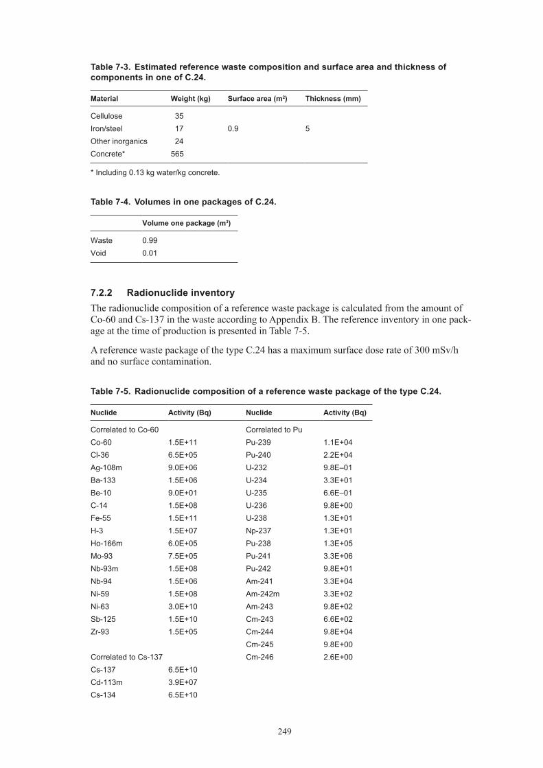
249
Table 7‑3. Estimated reference waste composition and surface area and thickness of components in one of C.24.
Material Weight (kg) Surface area (m2) Thickness (mm)
Cellulose 35Iron/steel 17 0.9 5Other inorganics 24Concrete* 565
* Including 0.13 kg water/kg concrete.
Table 7‑4. Volumes in one packages of C.24.
Volume one package (m3)
Waste 0.99Void 0.01
7.2.2 Radionuclide inventoryThe radionuclide composition of a reference waste package is calculated from the amount of Co-60 and Cs-137 in the waste according to Appendix B. The reference inventory in one pack-age at the time of production is presented in Table 7-5.
A reference waste package of the type C.24 has a maximum surface dose rate of 300 mSv/h and no surface contamination.
Table 7‑5. Radionuclide composition of a reference waste package of the type C.24.
Nuclide Activity (Bq) Nuclide Activity (Bq)
Correlated to Co-60 Correlated to PuCo-60 1.5E+11 Pu-239 1.1E+04Cl-36 6.5E+05 Pu-240 2.2E+04Ag-108m 9.0E+06 U-232 9.8E–01Ba-133 1.5E+06 U-234 3.3E+01Be-10 9.0E+01 U-235 6.6E–01C-14 1.5E+08 U-236 9.8E+00Fe-55 1.5E+11 U-238 1.3E+01H-3 1.5E+07 Np-237 1.3E+01Ho-166m 6.0E+05 Pu-238 1.3E+05Mo-93 7.5E+05 Pu-241 3.3E+06Nb-93m 1.5E+08 Pu-242 9.8E+01Nb-94 1.5E+06 Am-241 3.3E+04Ni-59 1.5E+08 Am-242m 3.3E+02Ni-63 3.0E+10 Am-243 9.8E+02Sb-125 1.5E+10 Cm-243 6.6E+02Zr-93 1.5E+05 Cm-244 9.8E+04
Cm-245 9.8E+00Correlated to Cs-137 Cm-246 2.6E+00Cs-137 6.5E+10Cd-113m 3.9E+07Cs-134 6.5E+10

250
Nuclide Activity (Bq) Nuclide Activity (Bq)
Cs-135 3.3E+05Eu-152 4.6E+06Eu-154 6.5E+09Eu-155 4.6E+09I-129 2.0E+04Pd-107 6.5E+04Pm-147 5.9E+10Ru-106 3.3E+08Se-79 2.6E+05Sm-151 2.0E+08Sn-126 3.3E+04Sr-90 6.5E+09Tc-99 3.3E+08
7.3 Uncertainties• ProductionofC.24isestimatedtooptimiseavailablevolumeinSilo,probablythetotal
production of C.24 will be lower than foreseen above.

251
8 R.02
8.1 Waste type description8.1.1 Waste packageGeneralThe R.02 waste type consists of 1.73 m3 concrete moulds containing ion-exchange resins and inert filter-aid in a concrete matrix. The raw waste material consists of ion exchange resins and filter aids generated at the Ringhals nuclear power plant. The material is classified as inter-mediate level waste. All data comes from /Eriksson 1990, Johansson 2000, Triumf 2007/.
Following restrictions are always applicable on this waste:
• ThegeneralrestrictionslistedinSection1.1.
PackagingThe mould is a cubic box made of reinforced concrete with the dimensions 1.2×1.2×1.2 m. The walls are normally 10 cm thick but can in some exceptional cases be 25 cm thick. The rein-forcement is made of steel bars with a total surface of 7.9 m2 and a weight of 160 kg in a 10-cm mould and 11.8 m2 and 250 kg in a 25-cm mould. The 10-cm mould weighs approxi mately 1,600 kg and the 25-cm weighs about 3,100 kg. A stirrer made of carbon steel is included in the waste package. It weighs 16 kg and has an estimated surface of 1 m2. To avoid cracking of the mould, due to expansion of the concrete matrix, a lining with compressible material (polyethene or polystyrene) is put inside the walls of the mould. The lining has a thickness of 20 mm and a total weight of 10 kg in a 10-cm mould and 5 mm and approximately 1 kg in a 25-cm mould. The variations between moulds are minimal.
Some changes in the design have been made since the start of production of this package. Before 1976 no lining was used. Some changes have been made regarding reinforcement and steel details in the mould. For the lid Betokem EXM-4 was used, nowadays Fiberbruk VF50 is used. Today no chemical cement additives are used but earlier Silix GP and Sika AER were used.
The weight of a package including waste and is approximately 3,400 kg but differs between 3,000–3,700 kg. The maximum allowed weight of a waste package is 4,000 kg.
Treatment and conditioningThe waste, used ion-exchange resins, is pumped into the mould and cement is added. If needed, water is added. When the cement is added the stirrer is started and the waste matrix is mixed for 60 minutes. The matrix is then allowed to harden for two days. Pouring concrete on top of the matrix then makes a lid. The concrete is allowed 24 hours to harden before the waste is transported to interim storage. The lid is at least 10 cm thick.
8.1.2 Materials – chemical compositionThe amounts of different materials in a R.02 mould are given in Table 8-1. The waste is well defined and consists of ion exchange resins and filter-aid with radionuclides.
The resins are:
• BeadresinfromPWR:cleaningoftheprimaryreactorcircuit(system334),thefuelponds(system 324), the waste water (system 342), water from the secondary side of the steam generators (system 417/337) and from drainage water.

252
• BeadresinfromBWR:systemsforcleaningreactorwater(system331),treatmentofliquidwaste (system 342), analytical ion-exchangers (system 336) and cleaning of fuel ponds (system 324).
• PowderresinsfromBWR:cleaningofcondensate(system332),fuelponds(system324)and treatment of liquid waste (system 324). The resins from liquid waste treatment contain filter-aids.
Resins from the PWR-reactors contain boric acid (H3BO3) up to 90 g/kg of resin. Some resins contain lithium. Resins from system 417/337 can contain ammonia and hydrazine.
The weight of the raw waste material is normally 130 kg of ion exchange resin per package but the weight varies, see Table 8-1.
The matrix is made of cement. The specific brand of cement has changed during the years of production of this waste type. The brand used nowadays is Skövde standardcement. In earlier days Limhamn LH-cement was used.
Table 8‑1. Amounts of different material in waste type R.02 (per package).
Material Weight (kg) Weight (%)
Ion-exchange resin 100–150 5.9–12.0Cement* 1,100–1,600 88.0–94.1
* Including water 0.4 kg/kg cement.
8.1.3 Radionuclide inventoryBefore the waste is transported from Ringhals NPP to SFR 1 a measurement of gamma emitting nuclides is performed. Dominating nuclides are Co-60 and Cs-137. The amounts of these nuclides are between 0 and 1.4·1012 Bq for Co-60 and between 0 and 7.7·1011 Bq for Cs-137. Other nuclides than gamma emitting ones must be calculated according to Appendix B.
The dose rate limit for this package is 500 mSv/h on the surface. Normal dose rate at 1 m is 4 mSv/h but varies between 0–14 mSv/h. The surface contamination should not exceed 40 kBq/m2 for gamma and beta and 4 kBq/m2 for alpha emitting nuclides on the package.
8.1.4 Waste productionThe waste type has been in production since 1984 and is still in production even though in a small scale. Type R.16 is used for this kind of waste nowadays, see Appendix A.
8.2 Reference waste type description8.2.1 Waste package and materialTable 8-2 shows the content of different materials and the steel surface areas of the packaging in a reference package.
The assumed composition of the waste in a reference waste package of R.02 is given in Table 8-3.
The estimated volumes of the waste, the packaging materials and the void volume inside the package for a reference package are given in Table 8-4. The waste volume is estimated from the weights of the waste components in Table 8-3 and approximate densities of the different material. Average void is estimated to 15% in a package.
Void and waste volume is specified in Table 8-4.

253
Table 8‑2. Estimated reference packaging composition and surface area and thickness of components in concrete mould of R.02.
Component Material Weight (kg) Surface area (m2) Thickness (mm)
Concrete box Concrete 1,340 100Reinforcement Steel 261 10 12Steel lid Steel 13 1.8 2Stirrer Steel 16 1 5Other organics Polyethene 10
Table 8‑3. Estimated reference waste composition and surface area and thickness of components in one of R.02.
Material Weight (kg)
Ion-exchange resin 130Cement* 1,400
* Including water 0.4 kg/kg cement.
Table 8‑4. Volumes in one waste packages of R.02.
Volume one package (m3)
Waste 0.85Void 0.15
8.2.2 Radionuclide inventoryThe radionuclide composition of a reference waste package is calculated from the amount of Co-60 and Cs-137 in the waste according to Appendix B. The reference inventory in one pack-age at the time of production is presented in Table 8-5.
A reference waste package of the type R.02 has a maximum surface dose rate of 500 mSv/h and no surface contamination.
Table 8‑5. Radionuclide composition of a reference waste package of the type R.02.
Nuclide Activity (Bq) Nuclide Activity (Bq)
Correlated to Co-60 Correlated to PuCo-60 5.0E+10 Pu-239 5.0E+05Cl-36 3.0E+04 Pu-240 1.0E+06Ag-108m 3.0E+06 U-232 4.5E+01Ba-133 5.0E+05 U-234 1.5E+03Be-10 3.0E+01 U-235 3.0E+01C-14 1.5E+08 U-236 4.5E+02Fe-55 5.0E+10 U-238 6.1E+02H-3 5.0E+06 Np-237 6.1E+02Ho-166m 2.0E+05 Pu-238 2.5E+06Mo-93 5.0E+04 Pu-241 1.5E+08Nb-93m 5.0E+07 Pu-242 4.5E+03Nb-94 5.0E+05 Am-241 8.9E+05

254
Nuclide Activity (Bq) Nuclide Activity (Bq)
Ni-59 5.0E+07 Am-242m 1.5E+04Ni-63 4.0E+09 Am-243 4.5E+04Sb-125 5.0E+09 Cm-243 3.0E+04Zr-93 5.0E+04 Cm-244 9.8E+05
Cm-245 4.5E+02Correlated to Cs-137 Cm-246 1.2E+02Cs-137 5.1E+10Cd-113m 3.1E+07Cs-134 3.2E+10Cs-135 5.1E+05Eu-152 3.6E+06Eu-154 5.1E+09Eu-155 3.6E+09I-129 1.5E+05Pd-107 5.1E+04Pm-147 4.6E+10Ru-106 2.5E+08Se-79 2.0E+05Sm-151 1.5E+08Sn-126 2.5E+04Sr-90 5.1E+09Tc-99 4.6E+07
8.3 Uncertainties• GeneraluncertaintiesaredescribedinSection1.3.
255
9 R.16
9.1 Waste type description9.1.1 Waste packageGeneralThe R.16 waste type consists of 1.73 m3 steel moulds containing ion-exchange resins and inert filter-aid in a concrete matrix. The raw waste material consists of ion exchange resins and filter aids generated at the Ringhals nuclear power plant. The material is classified as intermediate level waste. Data comes from /Ahlqvist 1998, Johansson 2000, Triumf 2007/.
Following restrictions are always applicable on this waste:
• ThegeneralrestrictionslistedinSection1.1.
PackagingThe mould is a cubic box made of steel with the dimensions 1.2×1.2×1.2 m. The wall is 5 mm thick, the bottom is 6 mm thick. The mould weighs approximately 425 kg and the surface area is approximately 20 m2. The variations between moulds are minimal. No major change in design has been made since the start of production of this package.
The weight in total of a package including waste and is approximately 3,200 kg but differs between 2,700–3,500 kg. The maximum allowed weight of a waste package is 5,000 kg.
Treatment and conditioningThe waste, used ion-exchange resin, is pumped into the mould and cement is added. If needed, water is added. When the cement is added the stirrer is started and the waste matrix is mixed for 60 minutes. The matrix is then allowed to harden for two days. Pouring concrete on top of the matrix then makes a lid. The concrete is allowed 24 hours to harden before the waste is transported to interim storage. The lid is at least 10 cm thick.
9.1.2 Materials – chemical compositionThe amounts of different materials in a R.16 mould are given in Table 9-1. The waste is well defined and consists of ion exchange resins and filter-aid with radionuclides.
The resins are:
• BeadresinfromPWR:cleaningoftheprimaryreactorcircuit(system334),thefuelponds(system 324), the waste water (system 342), water from the secondary side of the steam generators (system 417/337) and from drainage water.
• BeadresinfromBWR:systemsforcleaningreactorwater(system331),treatmentofliquidwaste (system 342), analytical ion-exchangers (system 336) and cleaning of fuel ponds (system 324).
• PowderresinsfromBWR:cleaningofcondensate(system332),fuelponds(system324)and treatment of liquid waste (system 324). The resins from liquid waste treatment contain filter-aids.
Resins from the PWR-reactors contain boric acid (H3BO3) up to 90 g/kg of resin. Some resins contain lithium. Resins from system 417/337 can contain ammonia and hydrazine.
The weight of the raw waste material is normally 130 kg of ion exchange resin per package but it varies, see Table 9-1.

256
The matrix is made of cement. The brand used is Skövde standardcement. Nowadays also Degerham standardcement can be used. Silix GP and Sika AER was used as additives until 1997 (and a few exceptions during 1998), from 1997 to 1998 Hydrafix was used and from 1997 a special additive is used (brand name is kept on commercial secrecy by demand from Ringhals NPP).
Table 9‑1. Amounts of different material in waste type R.16 (per package).
Material Weight (kg) Weight (%)
Ion-exchange resin 10–500 0.4–26.3Cement* 1,400–2,800 99.6–73.7
* Including water 0.4 kg/kg cement.
9.1.3 Radionuclide inventoryBefore the waste is transported from Ringhals NPP to SFR 1 a measurement of gamma emitting nuclides is performed. Dominating nuclides are Co-60 and Cs-137. The amounts of these nuclides are between 0 and 9.0·1011 Bq for Co-60 and between 0 and 2.0·1011 Bq for Cs-137. Other nuclides than gamma emitting ones must be calculated according to Appendix B.
The dose rate limit for this package is 500 mSv/h on the surface. Normal dose rate at 1 m is 9 mSv/h but varies between 0.1–35 mSv/h. The surface contamination should not exceed 40 kBq/m2 for gamma and beta and 4 kBq/m2 for alpha emitting nuclides on the package. The waste packages are usually free of contamination.
9.1.4 Waste productionThe waste type has been in production since 1991 and is still in production. The annual produc-tion is estimated to 70 packages per year, see Appendix A.
9.2 Reference waste type description9.2.1 Waste package and materialTable 9-2 shows the content of different materials and the steel surface areas of the packaging in a reference package.
The assumed composition of the waste in a reference waste package of R.16 is given in Table 9-3.
The estimated volumes of the waste, the packaging materials and the void volume inside the package for a reference package are given in Table 9-4. The waste volume is estimated from the weights of the waste components in Table 9-3 and approximate densities of the different material. Average void is estimated to 5% in a package.
Void and waste volume is specified in Table 9-4.
Table 9‑2. Estimated reference packaging composition and surface area and thickness of components in concrete mould of R.16.
Component Material Weight (kg) Surface area (m2) Thickness (mm)
Steel box Stainless steel 400 17 5Stirrer Stainless steel 25 3 2

257
Table 9‑3. Estimated reference waste composition and surface area and thickness of components in one of R.16.
Material Weight (kg)
Ion-exchange resin 250Cement* 2,100
* Including water 0.4 kg/kg cement.
Table 9‑4. Volumes in one waste packages of R.16.
Volume one package (m3)
Waste 1.615Void 0.085
9.2.2 Radionuclide inventoryThe radionuclide composition of a reference waste package is calculated from the amount of Co-60 and Cs-137 in the waste according to Appendix B. The reference inventory in one pack-age at the time of production is presented in Table 9-5.
A reference waste package of the type R.16 has a maximum surface dose rate of 500 mSv/h and no surface contamination.
Table 9‑5. Radionuclide composition of a reference waste package of the type R.16.
Nuclide Activity (Bq) Nuclide Activity (Bq)
Correlated to Co-60 Correlated to PuCo-60 1.9E+11 Pu-239 1.8E+06Cl-36 1.2E+05 Pu-240 3.5E+06Ag-108m 1.2E+07 U-232 1.7E+02Ba-133 1.9E+06 U-234 5.7E+03Be-10 1.2E+02 U-235 1.1E+02C-14 5.8E+08 U-236 1.7E+03Fe-55 1.9E+11 U-238 2.3E+03H-3 1.9E+07 Np-237 2.3E+03Ho-166m 7.7E+05 Pu-238 9.6E+06Mo-93 1.9E+05 Pu-241 5.7E+08Nb-93m 1.9E+08 Pu-242 1.7E+04Nb-94 1.9E+06 Am-241 3.4E+06Ni-59 1.9E+08 Am-242m 5.7E+04Ni-63 1.6E+10 Am-243 1.7E+05Sb-125 1.9E+10 Cm-243 1.1E+05Zr-93 1.9E+05 Cm-244 3.7E+06
Cm-245 1.7E+03Correlated to Cs-137 Cm-246 4.6E+02Cs-137 2.9E+10Cd-113m 1.8E+07Cs-134 2.0E+10Cs-135 2.9E+05Eu-152 2.1E+06

258
Nuclide Activity (Bq) Nuclide Activity (Bq)
Eu-154 2.9E+09Eu-155 2.1E+09I-129 8.8E+04Pd-107 2.9E+04Pm-147 2.6E+10Ru-106 1.5E+08Se-79 1.2E+05Sm-151 8.8E+07Sn-126 1.5E+04Sr-90 2.9E+09Tc-99 2.6E+07
9.3 Uncertainties• ProductionofR.16isestimatedtooptimiseavailablevolumeinSilo,probablythetotal
production of R.16 will be lower than foreseen above.

259
10 S.04
10.1 Waste type description10.1.1 Waste packageGeneralThe S.04 waste type consists of a standard 200-litre drum containing ion exchange resins in a cement matrix. The raw waste material consists of ion exchange resins generated at the Studsvik research centre. The material is classified as intermediate level waste. All data comes from /Öberg 1997, Johansson 2000, Studsvik 2000/.
The physical properties and chemical conditions are well known. The following restrictions are always applicable:
• ThegeneralrestrictionslistedinSection1.1.
PackagingThe steel drum is made of stainless steel with diameter 0.57 m and 0.84 m in height. The wall thickness is 1.5 mm. The drum weighs approximately 60 kg and surface area is approximately 5.1 m2. To facilitate the handling in SFR the drums are placed four by four on a steel plate with the dimension 1.2 m ·1.2 m and the thickness of 4 mm. The weight of the steel plate is 66 kg with surface area of 4.0 m2. The variations between packages are minimal. No major changes in design have been made since the start of production of this package.
The weight in total of a package including waste and is approximately 350 kg. The maximum allowed weight of a waste package is 500 kg.
Treatment and conditioningThe ion exchange resin containing metal hydroxides and other substances is mixed with concrete in a custom-made facility at the Studsvik site. Cement is added in the drum and then the waste, used ion-exchange resin, and water is pumped into the drum.
When the waste is added the stirrer is started and the waste matrix is mixed. The matrix is then allowed to harden for one day. After measurements a steel lid is placed on top of the drum. The drums are placed on the steel plate when the drums are sent to SFR.
The void varies but is estimated to 0.01 m3 in a drum.
10.1.2 Materials – chemical compositionThe amounts of different materials in a S.04 drum are given in Table 10-1. The waste contains ion-exchange resins (bead-type) with metal hydroxides from the fuel ponds and primary circuits in the Studsvik R2-reactor. The weight of the raw waste material is normally 65 kg ion-exchange resin per package but varies, see Table 10-1.
The matrix is made of concrete. No cement additives are used.
Table 10‑1. Amounts of different material in waste type S.04 (per package).
Material Weight (kg) Weight (%)
Ion-exchange resin 20 25Concrete 60 75

260
10.1.3 Radionuclide inventoryBefore the waste is solidified a measurement of gamma emitting nuclides is performed. Dominating nuclides are Co-60 and Cs-137. The amounts of these nuclides are between 0 and 4.6·108 Bq for Co-60 and between 0 and 1.2·109 Bq for Cs-137. Other nuclides than gamma emitting ones must be calculated according to Appendix B.
The dose rate limit for this package is 50 mSv/h. No estimation on variation of dose rates are available in referred documents. The surface contamination should not exceed 40 kBq/m2 for gamma and beta and 4 kBq/m2 for alpha emitting nuclides. The waste packages are usually free of contamination.
10.1.4 Waste productionThe annual production is estimated to 4, see Appendix A.
10.2 Reference waste type description10.2.1 Waste package and materialTable 10-2 shows the content of different materials and the surface areas of the packaging in S.04 package from Studsvik. Since the steel plate and expansion box is shared between four drums ¼ of the plate and box is included in a package of S.04.
The assumed composition of the waste in a reference waste package of S.04 is given in Table 9-3.
Void and waste volume is specified in Table 10-4.
Table 10‑2. Estimated reference packaging composition and surface area and thickness of components in each steel drum and one ¼ of a steel plate and expansion box of S.04.
Component Material Weight (kg) Surface area (m2) Thickness (mm)
Steel drum steel 60 5.1 1.5Steel plate steel 16.6 1.0 4
Table 10‑3. Estimated reference waste composition in one steel drum of S.04.
Material Weight (kg)
Ion-exchange resin 65Cement* 238
* Including water 0.4 kg/kg cement.
Table 10‑4. Volumes in one waste packages of steel drums including ¼ steel plate and expansion box per drum of S.04.
Volume one package (m3)
Waste 0.2Void 0.01

261
10.2.2 Radionuclide inventory
The radionuclide composition of a reference waste package is calculated from the amount of Co-60 and Cs-137 in the waste according to Appendix B. The reference inventory in one pack-age at the time of production is presented in Table 10-5.
A reference waste package of the type S.04 has a surface dose rate of 50 mSv/h and no surface contamination.
Table 10‑5. Radionuclide composition of a reference waste package of the type S.04.
Nuclide Activity (Bq) Nuclide Activity (Bq)
Correlated to Co-60 Correlated to PuCo-60 5.3E+07 Pu-239 7.7E+02Cl-36 3.2E+01 Pu-240 1.6E+03Ag-108m 3.2E+03 U-232 7.0E–02Ba-133 5.3E+02 U-234 2.3E+00Be-10 3.2E–02 U-235 4.6E–02C-14 1.6E+05 U-236 7.0E–01Fe-55 5.3E+07 U-238 9.3E–01H-3 5.3E+03 Np-237 9.3E–01Ho-166m 2.1E+02 Pu-238 1.5E+06Mo-93 5.3E+01 Pu-241 2.3E+05Nb-93m 5.3E+04 Pu-242 7.0E+00Nb-94 5.3E+02 Am-241 2.3E+03Ni-59 5.3E+04 Am-242m 2.3E+01Ni-63 4.2E+06 Am-243 7.0E+01Sb-125 5.3E+06 Cm-243 4.6E+01Zr-93 5.3E+01 Cm-244 1.6E+06
Cm-245 7.0E–01Correlated to Cs-137 Cm-246 1.9E–01Cs-137 2.0E+07Cd-113m 1.2E+04Cs-134 8.2E+06Cs-135 2.0E+02Eu-152 2.4E+06Eu-154 8.3E+05Eu-155 1.4E+06I-129 6.0E+01Pd-107 2.0E+01Pm-147 1.8E+07Ru-106 3.2E+06Se-79 8.0E+01Sm-151 6.0E+04Sn-126 1.0E+01Sr-90 2.0E+06Tc-99 1.8E+04
10.3 Uncertainties• GeneraluncertaintiesaredescribedinSection1.3.

262
11 S.11
11.1 Waste type description11.1.1 Waste packageGeneralThe S.11 waste type consists of 1.73 m3 steel moulds containing ion-exchange resins and sludges in a cement matrix. The raw waste material consists of ion-exchange resins and sludges generated at the Studsvik site or at the closed down Ågesta Reactor. The material is classified as intermediate level waste. All data comes from /Rolandsson 1998, Johansson 2000/.
Following restrictions are always applicable on this waste:
• ThegeneralrestrictionslistedinSection1.1.
PackagingThe mould is a cubic box made of steel with the dimensions 1.2×1.2×1.2 m. The wall is 5 mm thick, the bottom is 6 mm thick. The mould weighs approximately 425 kg including stirrer and the surface area is approximately 20 m2. The variations between moulds are minimal.
The weight in total of a package including waste and is approximately 4,000 kg. The maximum allowed weight of a waste package is 5,000 kg.
Treatment and conditioningThe waste is pumped into the mould and cement is added. If needed, water is added. When the cement is added the stirrer is started and the waste matrix is mixed. The matrix is then allowed to harden. Pouring concrete on top of the matrix then makes a lid. The concrete is allowed 24 hours to harden before the waste is transported to interim storage. The lid is at least 10 cm thick.
11.1.2 Materials – chemical compositionThe amounts of different materials in a S.11 mould are given in Table 11-1. The waste has been thoroughly analysed and is fairly well defined. It consists of ion exchange resins and sludges containing radionuclides. No harmful amounts of complexing agents are present in the waste matrix that could improve mobility of the radionuclides.
The weight of the raw waste material is normally 667 kg of ion exchange resin and 333 kg sludge per package but varies, some parameters have an estimated variation see Table 11-1.
The matrix is made of cement. No additives are used in this waste.
Table 11‑1. Amounts of different material in waste type S.11 (per package).
Material Weight (kg) Weight (%)
Ion-exchange resin 667 21–26.2Sludge 333 10.7–13.1Cellulose 3 0–0.1Cement* 1,540–2,100 60.6–67.7
* Including water 0.4 kg/kg cement.

263
11.1.3 Radionuclide inventoryBefore the waste is transported from Studsvik to SFR 1 a measurement of gamma emitting nuclides is performed. Dominating nuclides are Co-60 and Cs-137, no data is available since no production of waste packages has been done yet. Other nuclides than gamma emitting ones must be calculated according to Appendix B.
The dose rate limit for this package is 5 mSv/h on the surface. No variation on dose rate is available since no production of waste packages has been done yet. The surface contamination should not exceed 40 kBq/m2 for gamma and beta and 4 kBq/m2 for alpha emitting nuclides on the package. Usually the packages are free of contamination.
11.1.4 Waste productionThe waste type has not yet been put in production. The amount of waste is limited to about 50 m3 stored in a Silo in at the Studsvik site.
11.2 Reference waste type description11.2.1 Waste package and materialTable 11-2 shows the content of different materials and the steel surface areas of the packaging in a reference package.
The assumed composition of the waste in a reference waste package of S.11 is given in Table 11-3.
The estimated volumes of the waste, the packaging materials and the void volume inside the package for a reference package are given in Table 11-4. The waste volume is estimated from the weights of the waste components in Table 11-3 and approximate densities of the different material. Average void is estimated to 5% in a package.
Void and waste volume is specified in Table 11-4.
Table 11‑2. Estimated reference packaging composition and surface area and thickness of components in concrete mould of S.11.
Component Material Weight (kg) Surface area (m2) Thickness (mm)
Steel box Stainless steel 400 17 5Stirrer Stainless steel 25 3 2
Table 11‑3. Estimated reference waste composition and surface area and thickness of components in one of S.11.
Material Weight (kg)
Ion-exchange resin 667Sludge 333Cellulose 3Cement* 1,820
* Including water 0.4 kg/kg cement.

264
Table 11‑4. Volumes in one packages of S.11.
Volume one package (m3)
Waste 1.615Void 0.085
11.2.2 Radionuclide inventoryThe radionuclide composition of a reference waste package is calculated from the amount of Co-60 and Cs-137 in the waste according to Appendix B. The reference inventory in one pack-age at the time of production is presented in Table 11-5.
A reference waste package of the type S.11 has a surface dose rate of 5 mSv/h and no surface contamination.
Table 11‑5. Radionuclide composition of a reference waste package of the type S.11.
Nuclide Activity (Bq) Nuclide Activity (Bq)
Correlated to Co-60 Correlated to PuCo-60 3.0E+08 Pu-239 1.3E+07Cl-36 1.8E+02 Pu-240 2.6E+07Ag-108m 4.7E+05 U-232 1.2E+03Ba-133 3.3E+05 U-234 3.9E+04Be-10 1.8E–01 U-235 7.7E+02C-14 9.1E+05 U-236 1.2E+04Fe-55 3.0E+08 U-238 1.6E+04H-3 3.0E+04 Np-237 1.6E+04Ho-166m 1.2E+03 Pu-238 7.3E+07Mo-93 3.0E+02 Pu-241 3.9E+09Nb-93m 3.0E+05 Pu-242 1.2E+05Nb-94 3.0E+03 Am-241 3.4E+07Ni-59 3.0E+05 Am-242m 3.9E+05Ni-63 2.4E+07 Am-243 1.2E+06Sb-125 3.0E+07 Cm-243 7.7E+05Zr-93 3.0E+02 Cm-244 1.1E+07
Cm-245 1.2E+04Correlated to Cs-137 Cm-246 3.1E+03Cs-137 7.2E+09Cd-113m 4.3E+06Cs-134 2.0E+09Cs-135 7.2E+04Eu-152 5.1E+05Eu-154 6.1E+06Eu-155 4.1E+08I-129 2.2E+04Pd-107 7.2E+03Pm-147 6.5E+09Ru-106 3.6E+07

265
Nuclide Activity (Bq) Nuclide Activity (Bq)
Se-79 2.9E+04Sm-151 2.2E+07Sn-126 3.6E+03Sr-90 7.2E+08Tc-99 6.5E+06
11.3 Uncertainties• GeneraluncertaintiesaredescribedinSection1.3.

266
12 S.24
12.1 Waste type description12.1.1 Waste packageGeneralThe S.24 waste type consists of 1.73 m3 concrete moulds with scrap metal in a concrete matrix. Waste material consists of iron/steel, aluminium and other inorganic material generated at Studsvik nuclear research centre. This package is supposed to contain smoke detectors with the dominating radionuclide Am-241. The material is classified as intermediate level waste. All data comes from /Chyssler 1997, Johansson 2000/. The packages are not produced yet.
The physical properties and chemical conditions can vary a lot, but the following restrictions are always applicable on this waste:
• ThegeneralrestrictionslistedinSection1.1.
PackagingThe mould is a cubic box made of reinforced concrete with the dimensions 1.2×1.2×1.2 m. The walls are 10 cm thick. The reinforcement is made of 12 mm steel bars with a total surface of 10 m2. The 10-cm mould weighs approximately 1,600 kg. The variations between moulds are minimal.
The maximum allowed weight of a waste package is 5,000 kg.
Treatment and conditioningWaste, mostly smoke detectors are placed in the mould, which is then filled with concrete. Pouring concrete on top of the package makes a lid.
12.1.2 Materials – chemical compositionThe amounts of different materials in a S.24 mould are given in Table 12-1. The waste is fairly well defined and consists mainly of smoke detectors. Some other scrap metal and other inorganic waste could be present. No variation of material is estimated.
The matrix is made of concrete.
Table 12‑1. Amounts of different material in waste type S.24 (per package).
Material Weight (kg) Area (m2) Weight (%)
Iron/steel 113 5.8 13.8Aluminium 3.8 0.6 0.5Other inorganic material 139 16.9Concrete* 565 68.8
* Including 0.13 kg water/kg concrete.
12.1.3 Radionuclide inventoryThe dominating nuclide is Am-241, the amount in total is estimated to 5.0·1011 Bq. Other nuclides may be present but amounts will probably be very small.

267
The surface dose rate limit for this package is 500 mSv/h but the actual dose rate will probably be a lot less. The contamination on surface should not exceed 40 kBq/m2 for gamma and beta and 4 kBq/m2 for alpha emitting nuclides on the package. Based on experience of other waste type no contamination is expected.
12.1.4 Waste productionThe annual production is estimated to 3, see Appendix A.
12.2 Reference waste type description12.2.1 Waste package and materialThe number of packages that will be produced is calculated to 2 packages during the operation of Studsvik.
Table 12-2 shows the content of different materials and the steel surface areas of the packaging in a reference package.
The assumed composition of the waste in a reference waste package of S.24 is given in Table 12-3.
The estimated volumes of the waste and the packaging materials and the void volume inside the package for a typical package of concrete box are given in Table 12-4. The waste volume is estimated from the weights of the waste components in Table 13-3 and approximate densities of the different material. Average void is estimated to 5% in a package.
Void and waste volume is specified in Table 12-4.
Table 12‑2. Estimated reference packaging composition, surface area and thickness of components in concrete mould of S.24.
Component Material Weight (kg) Surface area (m2) Thickness (mm)
Concrete box Concrete 1,340 10Reinforcement Steel 261 10 12Lid Steel 13 1.8 2
Table 12‑3. Estimated reference waste composition and surface area and thickness of components in one of S.24.
Material Weight (kg) Surface area (m2) Thickness (mm)
Iron/steel 113 5.8Aluminium 3.8 0.6 5Other inorganic material 139 5Concrete* 565
* Including 0.13 kg water/kg concrete.
Table 12‑4. Volumes in one reference waste packages of S.24.
Volume one package (m3)
Waste 0.95Void 0.05

268
12.2.2 Radionuclide inventoryThe reference inventory in one package at the time of production has not been calculated since it is assumed that the activity in the waste comes solely from the smoke detectors, i.e. only Am-241, the amount in total is 5.0·1011 Bq.
A reference waste package of the type S.24 has a surface dose rate of 500 mSv/h and no surface contamination.
12.3 Uncertainties• GeneraluncertaintiesaredescribedinSection1.3.
• Thistypehasnotbeenproducedyet,therearelargeuncertaintiesregardingalldata.

269
13 Other waste types
Since SFR 1 still is in operation there is always the possibility that new waste types are needed. It is not possible to define these types per se. Since the Silo is not well suited for odd geometries, no other waste types have been assumed.
13.1 UncertaintiesUp to this date no kind of odd wastes have been disposed off in the Silo, in the future odd waste types could be disposed off.

270
14 References
Ahlqvist M, 1998. Typbeskrivning för plåtkokiller innehållande cementingjutna jonbytarmassor och filterhjälpmedel. Vattenfall Ringhals Rapport 0682/98.
Chyssler J, 1997. Typbeskrivning S.23 betongkokiller innehållande dubbellocksfat med sopor och skrotavfall från Studsvik för deponering i BMA. Studsvik Radwaste Arbetsrapport Draft version 1997.
Eriksson A, 1990. Typbeskrivning av betongkokiller innehållande cementingjuten jonbytar-massa och filterhjälpmedel. Vattenfall Ringhalsverket Rapport 218/90.
Ingemansson K-E, 1999. Oskarshamnsverket – Typbeskrivning av betongkokiller innehållande cementingjuten jonbytarmassa och filterhjälpmedel, O.01 och O.02. OKG Instruktion Avfall Reg.nr I-0782.
Ingemansson K-E, 2000. Typbeskrivning O.24, av kokiller innehållande betongkringgjutna sopor och skrot med slutförvar Silo. OKG, Typbeskrivning reg.nr 2000-05085.
Jansson E, 1995. Forsmark 3 Typbeskrivning av bitumensolidifierat avfall i kokill för depone-ring i Silo. Forsmarks Kraftgrupp Beskrivning BES-3 343-009.
Johansson C, 2000. Beräkningsunderlag för normalkollin. SKB Drift PM 2000/15.
Jönsson J-E, 2006. Typbeskrivning B.04 – plåtfat innehållande cement solidifierade låg- och medelaktiva jonbytarmassor från Barsebäcks kärnkraftverk för deponering i Silo. Dok id 1820374.
Rolandsson S, 1998. Typbeskrivning av plåtkokiller innehållande cementingjutna jonbytar-massor och slam-S.11. Studsvik RadWaste Report Studsvik/ES-98/33.
Roth L, 1996. Typbeskrivning av avfallskollin – Bitumeningjutet medelaktivt avfall i plåtfat, beteckning B.06. Sydkraft Barsebäcksverket Rapport P1-9612-38.
Studsvik, 2000. Databases over radioactive waste, Maintained by Studsvik RadWaste [accessed 2000-07-01].
Triumf 2007. Triumf – database over radioactive operational waste in SFR 1 [accessed February 2007].
Öberg L, 1997. Typbeskrivning för avfallskolli från Studsvik plåtfat med cementingjuten jon-bytarmassa. Studsvik RadWaste Arbetsrapport RW-97/55.