archive.floridadisaster.orgarchive.floridadisaster.org/mitigation/rcmp/wind loss/condolr5...appendix...
TRANSCRIPT
APPENDIX B:
EXAMPLE DESIGN CALCULATIONS BY FBC, SBC 88, AND SBC 76
APPENDIX B: EXAMPLE DESIGN CALCULATIONS BY ASCE 7-98, SBC 88, AND SBC 76
This appendix contains one sample set of design calculations of the analysis completed in Section 4 of this report. This sample is for a Group I building designed according to Florida Building Code Section 1606 (based on ASCE 7-98), Standard Building Code 1988, and Standard Building Code 1976.
The dimensions of the building, and other key parameters such as truss spacing are defined on page B-3 under the section called “Geometry of Building”. A sample of the sizes of the windows, and doors are defined on page B-9. Once the configuration of the building is established, these calculations compute the design parameters for the following:
• Roof deck nailing,
• Fenestration design pressures,
• Roof-wall connection design,
The input parameters are the design wind speed and terrain exposure, and the internal pressure condition (Enclosed vs. Partially Enclosed), as appropriate. Note that SBC 76 and SBC 88 do not have an exposure variable.
This particular sample design has been prepared for 130 mph gust design wind speed in Terrain Exposure C for an Enclosed Building condition under FBC and 110 mph fastest mile wind speed under SBC. Recall that 110 mph fastest mile wind speed is equivalent to about 130 mph gust wind speed.
This set of calculations was repeated for each of the FBC/SBC combinations of wind speed, terrain exposure, and internal pressure condition listed in Table 2-1 for each
of the modeled buildings. The results of these calculations are summarized in Appendix A of this report.
One may note that the nailing patterns for wood decks on Group I buildings appear to be slightly weaker than those reported in the single family report, even though the wind loads are higher for two story than single story structures. This design calculation is based on a higher wood density, which is more common on commercial and large-scale residential projects. This higher wood density yields a higher nail pullout strength and thus the Group I designs reported here will use slightly fewer nails.
Version 1.3 – August 2002
B-2

FBC
W 38ft 2 o⋅+:= dimensions of buildingIntPressure in0 2⟨ ⟩:= IntPressure 0= L 192ft 2 o⋅+:=
∆ 24 in⋅:= Truss spacingCase 1:= Case 1 = C&C and
MWFRS for low rise bldgsRoof cover: Shingle
hwall 9 ft⋅:= Height of Wall, single story
Dead load of roof
DLroof 9 psf⋅:= Hip roof, shingle, trusses, underlayment (from SBC Appendix A)
DLsheath 0.5 in⋅( )0.4psf.125 in⋅
⋅:= DLsheath 1.6 psf=
Dead load of roof is composed of following: Truss/Sheathing (7 psf), Tile (10psf). If shingles are used, use 2 psf instead of 10 psf.
Lattic 30 psf⋅:= SBC Table 1604.1 φ 0.6:= Fraction of DeadLoad used in combination with Wind Load
Lfloor 40 psf⋅:=
Lroof 16 psf⋅:=
Miscellaneous: Contents, carpet, cabinets, fixtures)Wood Frame wall weight
Masonry Wall WeightDLmisc 15 psf⋅:=DLwall
10
55
psf⋅:=
ASCE7-98 (FBC) Loads on single story building with flat roof slope (less than 10 degrees)
Variables for Exposure
Variables for Enclosed/Part Encl.Input Parameters
in0 130 C Enclosed( ):= Enclosed 0≡
PartEnclosed 1≡Define design parameters
A
B
C
D
0
1
2
3
≡
Geometry of Building: Building Name: 0023 - Condo projectDesign Parameters
h22.18 22.18+
2
ft⋅:= ht of building h 22.18 ft=
V in0 0⟨ ⟩ mph⋅:= V 130mph=
I 1.0:= Importance for Class II Building θ atan012
:= θ 0deg= roof slope
Exp in0 1⟨ ⟩:= Exp 2= o 0.0 ft⋅:= overhang widthog 0 ft⋅:=
B-3Version 1.3 - Aug 2002
FBC
Dummy value in Case Int Pressure is invalid
posneg 0 1..:=GCpi0.18−
0.18
=GCpi0.18−
0.18
IntPressure Enclosed=if
0.55−
0.55
IntPressure PartEnclosed=if
20−
20
otherwise
:=
internal pressure range variable
Internal Pressure coefficient
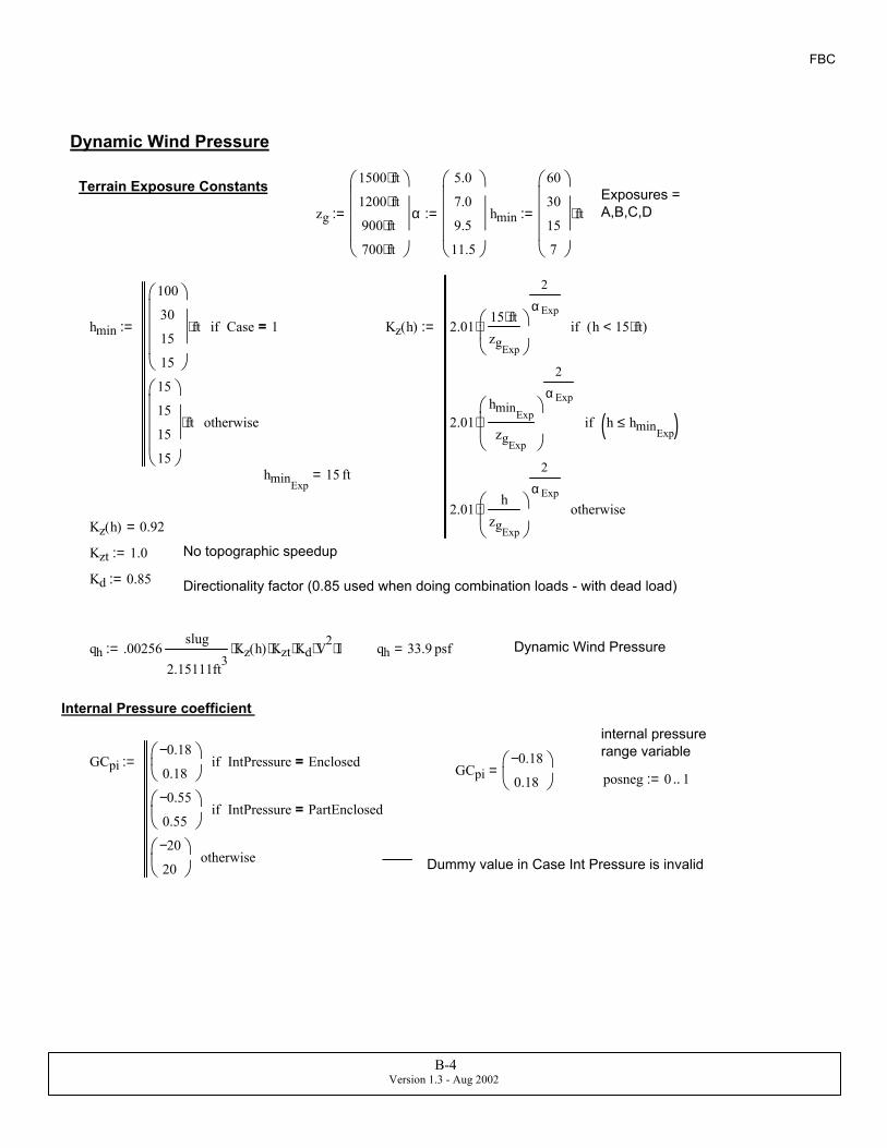
Dynamic Wind Pressureqh 33.9 psf=qh .00256slug
2.15111ft3Kz h( )⋅ Kzt⋅ Kd⋅ V2⋅ I⋅:=
Directionality factor (0.85 used when doing combination loads - with dead load)Kd 0.85:=
No topographic speedupKzt 1.0:=
Kz h( ) 0.92=
hminExp15 ft=
Kz h( ) 2.0115 ft⋅zgExp
2
α Exp⋅ h 15 ft⋅<( )if
2.01hminExp
zgExp
2
α Exp
⋅ h hminExp≤( )if
2.01h
zgExp
2
α Exp⋅ otherwise
:=hmin
100
30
15
15
ft⋅ Case 1=if
15
15
15
15
ft⋅ otherwise
:=
hmin
60
30
15
7
ft⋅:=α
5.0
7.0
9.5
11.5
:=zg
1500 ft⋅
1200 ft⋅
900 ft⋅
700 ft⋅
:=Exposures = A,B,C,D
Terrain Exposure Constants
Dynamic Wind Pressure
B-4Version 1.3 - Aug 2002

FBC
Gust Factor (Eqn 6-2)G 0.88=G 0.9251 1.7 gQ⋅ Iz⋅ Q⋅+
1 1.7 gv⋅ Iz⋅+
⋅:=
gv 3.4:=gQ 3.4:=
Q 0.92=Background Response (Eqn 6-4)Q
1
1 0.63W h+
Lz
0.63⋅+
:=
Integral Length Scale of Turbulence (Eqn 6-5)
Lz 427.06 ft=Lz lExpze
33 ft⋅
εExp
⋅:=
Turbulence Intensity (eqn 6-3)Iz 0.23=Iz cExp33 ft⋅
ze
1
6⋅:=
Equivalent height of structureze 15 ft=ze max ze( ):=ze0.6 h⋅
zminExp
:=
zmin
60
30
15
7
ft⋅:=c
0.45
0.3
0.2
0.15
:=ε
12
13
15
18
:=l
180
320
500
650
ft⋅:=
Terrain Exposure Constants from Table 6-4
Gust Factor:
B-5Version 1.3 - Aug 2002
FBC
Zone 3, ohang
Zone 2, ohangZone 3, overhang
Zone 1 , ohangZone 2, overhang Zone 5
Zone 4Alim_10deg
0
10 100 1000( )
10 100 1000( )
10 100 1000( )
10 500 1000( )
10 500 1000( )
10 100 500( )
10 100 500( )
10 100 1000( )
ft2⋅:=Zone 1 , overhangZone 3
Zone 2Zone 5
Zone 1 GCp_10deg
0
1−
0.3
0.9−
0.2
0.9−
0.2
1.8−
0.3
1.1−
0.2
1.1−
0.2
2.8−
0.3
1.1−
0.2
1.1−
0.2
0.91.1−
1
0.8−
0.7
0.8−
0.7
⋅
0.91.4−
1
0.8−
0.7
0.8−
0.7
⋅
1.7−
0
1.6−
0
1.1−
0
1.7−
0
1.6−
0
1.1−
0
2.8−
0
0.8−
0
0.8−
0
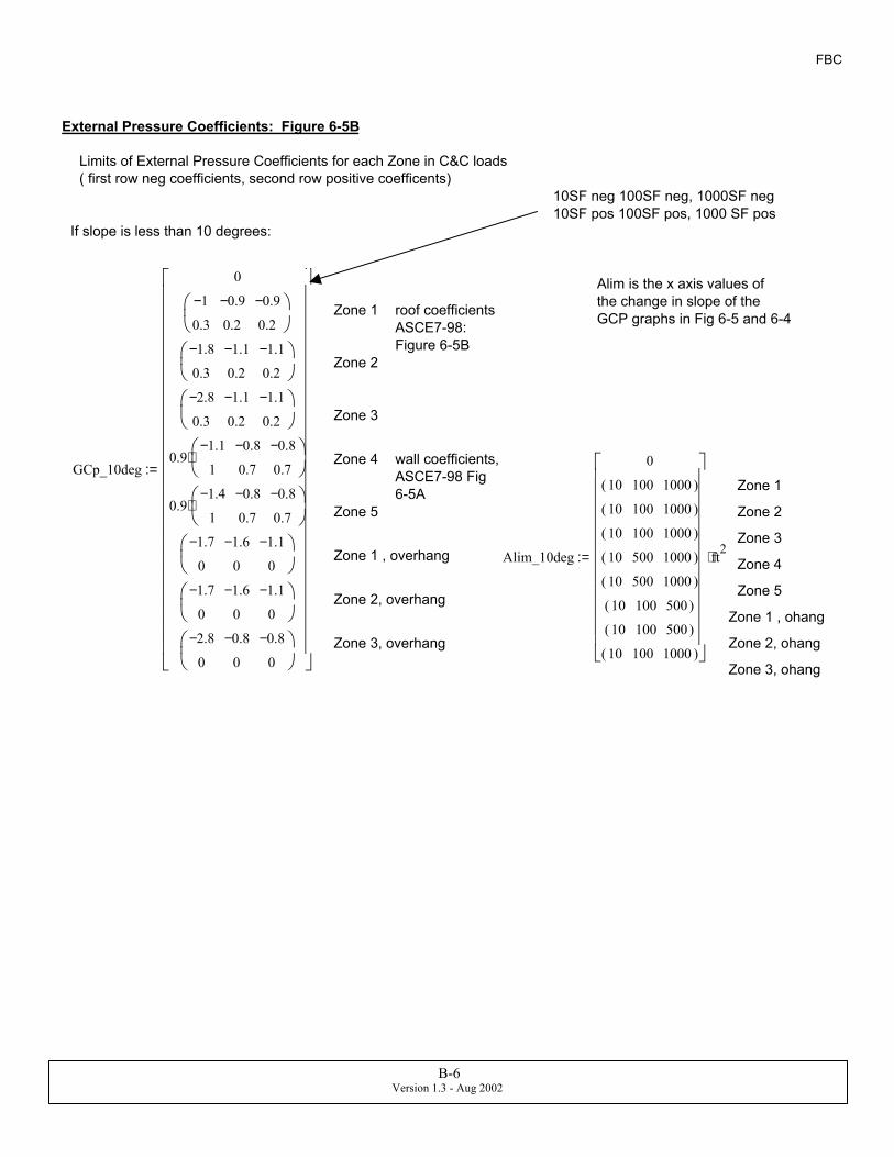
:=wall coefficients, ASCE7-98 Fig 6-5A
Zone 4
Zone 3
Zone 2
roof coefficients ASCE7-98: Figure 6-5B
Zone 1
Alim is the x axis values of the change in slope of the GCP graphs in Fig 6-5 and 6-4
If slope is less than 10 degrees:
10SF neg 100SF neg, 1000SF neg10SF pos 100SF pos, 1000 SF pos
Limits of External Pressure Coefficients for each Zone in C&C loads( first row neg coefficients, second row positive coefficents)
External Pressure Coefficients: Figure 6-5B
B-6Version 1.3 - Aug 2002

FBC
Zone 3, overhang
Zone 2, overhang
Zone 1 , overhang - assumed same as Zone 1 no overhang
Zone 5
GCp_45deg
0
1.0−
0.9
0.8−
0.8
0.8−
0.8
1.2−
0.9
1.0−
0.8
1.0−
0.8
1.2−
0.9
1.0−
0.8
1.0−
0.8
1.1−
1
0.8−
0.7
0.8−
0.7
1.4−
1
0.8−
0.7
0.8−
0.7
1.0−
0.9
0.8−
0.8
0.8−
0.8
2.0−
0
1.8−
0
1.8−
0
2.0−
0
1.8−
0
1.8−
0
:=wall coefficients, ASCE7-98 Fig 6-5A
Zone 4
Zone 3Alim_45deg
0
10 100 1000( )
10 100 1000( )
10 100 1000( )
10 500 1000( )
10 500 1000( )
10 100 1000( )
10 100 1000( )
10 100 1000( )
ft2⋅:=
Zone 2
roof coefficients ASCE7-98: Figure 6-5B
Zone 1
If slope is 30 to 45 degrees:
Zone 3, overhang
Zone 2, overhang
Zone 1 , overhang - assumed same as Zone 1 no overhang
Zone 5
GCp_30deg
0
0.9−
0.5
0.8−
0.3
0.8−
0.3
2.1−
0.5
1.4−
0.3
1.4−
0.3
2.1−
0.5
1.4−
0.3
1.4−
0.3
1.1−
1
0.8−
0.7
0.8−
0.7
1.4−
1
0.8−
0.7
0.8−
0.7
0.9−
0.5
0.8−
0.3
0.8−
0.3
2.2−
0
2.2−
0
2.2−
0
3.7−
0
2.5−
0
2.5−
0
:=wall coefficients, ASCE7-98 Fig 6-5A
Zone 4
Zone 3Alim_30deg
0
10 100 1000( )
10 100 1000( )
10 100 1000( )
10 500 1000( )
10 500 1000( )
10 100 1000( )
10 100 1000( )
10 100 1000( )
ft2⋅:=
Zone 2
roof coefficients ASCE7-98: Figure 6-5B
Zone 1
If slope is 10 to 30 degrees:
B-7Version 1.3 - Aug 2002

FBC
Select appropriate set of parameters according to slope of roof:θ 0deg=
GCp GCp_10deg θ 10 deg⋅≤( )if
GCp_30deg 10 deg⋅ θ< 30 deg⋅≤if
GCp_45deg 30 deg⋅ θ< 45 deg⋅≤if
0 otherwise
:= Alim Alim_10deg θ 10 deg⋅≤( )if
Alim_30deg 10 deg⋅ θ< 30 deg⋅≤if
Alim_45deg 30 deg⋅ θ< 45 deg⋅≤if
0 otherwise
:=
Calculate slopes of parts of pressure coefficient graphs for interpolation:
slopeGCp Zone( )GCpZone( ) 1⟨ ⟩ GCpZone( ) 0⟨ ⟩−
logAlimZone( ) 1⟨ ⟩
ft2
logAlimZone( ) 0⟨ ⟩
ft2
−
:=
Slope of first section of line
slope of secondary section of line (usually flat)slopeGCp2 Zone( )
GCpZone( ) 2⟨ ⟩ GCpZone( ) 1⟨ ⟩−
logAlimZone( ) 2⟨ ⟩
ft2
logAlimZone( ) 1⟨ ⟩
ft2
−
:=
GCp Area Zone,( ) GCpZone( ) 0⟨ ⟩ Area AlimZone( ) 0⟨ ⟩<if
slopeGCp Zone( )( ) logArea
ft2
logAlimZone( ) 0⟨ ⟩
ft2
−+
...
⋅
GCpZone( ) 0⟨ ⟩+
...
AlimZone( ) 0⟨ ⟩ Area≤ AlimZone( ) 1⟨ ⟩<if
slopeGCp2 Zone( )( ) logArea
ft2
logAlimZone( ) 1⟨ ⟩
ft2
−+
...
⋅
GCpZone( ) 1⟨ ⟩+
...
AlimZone( ) 1⟨ ⟩ Area≤ AlimZone( ) 2⟨ ⟩<if
GCpZone( ) 2⟨ ⟩ otherwise
:=
For Example:
GCp 11 ft2⋅ 4,( ) 0.98−
0.89
= GCp 10 ft2⋅ 5,( ) 1.26−
0.9
= GCp 50 ft2⋅ 1,( ) 0.93−
0.23
=
B-8Version 1.3 - Aug 2002

FBC
DP 4⟨ ⟩ 38.87−
35.82
psf=for example window : Design pressures are:
DP0 1 2 3 4 5 6 7 8 9
01
-38.87 -38.87 -38.04 -38.04 -38.87 -38.04 -38.87 -38.04 -38.87 -38.8735.82 35.82 34.99 34.99 35.82 34.99 35.82 34.99 35.82 35.82
psf=
Effective Area of fenestrations are set according to the area of the element resisting the load, as opposed to the area of the entire fenestration. For example, a sliding glass door is made of 3 doors spanning vertically, each door is 4x8. The doors do not transfer wind load horizontally, therefore the wind loads are correlated only over the single door, and thus instead of an effective area of 96 square feet, the effective area is 32 square feet.
DP j⟨ ⟩ qh GCp Fen Size⟨ ⟩( )j 1+ ft2⋅
→
Fen Zone⟨ ⟩( )j 1+
→ ,
GCpi+
⋅ Fen Zone⟨ ⟩( )
j 1+ 45≠if
qh GCp Fen Size⟨ ⟩( )j 1+ ft2⋅
→
5,
GCpi+
⋅ Fen Fraction⟨ ⟩( )
j 1+⋅
qh GCp Fen Size⟨ ⟩( )j 1+ ft2⋅
→
4,
GCpi+
⋅ 1 Fen Fraction⟨ ⟩( )
j 1+−
⋅+
...
otherwise
:=
j 0 rows Fen( ) 2−..:=
Fen
0 1 2 3 40123456789101112131415
0 0 0 0 00 1 1 14 40 2 2 14 40 3 3 20 40 4 4 20 40 5 5 14 40 6 6 20 40 7 7 14 40 8 8 20 40 9 9 14 40 10 10 14 40 11 11 20 40 12 12 20 40 13 13 14 40 14 14 20 40 15 15 14 4
=
rows Fen( ) 196=
Number of windows/doors
Zone 4:=Fen
D:\..\fen dp.xls
:= Size 3:=
Dummy Width and Height
The following input table was imported from an excel sheet that had a list of fens for this building. Each column represents the width, height, area, and zone of each fen respectively.
Window Design Pressure
B-9Version 1.3 - Aug 2002

FBC
GCp Area 3,( )1.94−
0.25
=
ppanel qh GCp Area 2,( ) GCpi+( )⋅:= ppanel55.13−
14.56
psf=
Resistance of single 8d Nail Load Case : Wind + 60% of dead load
qr 41lbfin
⋅:= 8d common nail, NDS 1997, page 30, diameter 0.131", specific Gravity 0.55 (Southern Pine)
lnail 2.5in:= length of nail, 8d
t .5 in⋅:= Plywood thickness = 1/2" (min thickness of code) Southern Pine SG - 0.55 on page 29, Table 12A of NDS-S97
lp lnail t−:= lp 2 in= penetration length
CD 1.6:= Duration factor for short term loads - wind = 10 minutes
Cm 1.0:= Condition Factor = assume that wood moisture content at time of construction is same as long term value
Rnail qr lp⋅ CD⋅ Cm⋅:= Rnail 131.2 lbf=
Design of Nailing Pattern for Roof DeckTributary area for single fastener: Area 10 ft2⋅:=
Zone1 Zone 2 Zone 3
GCp Area 1,( )1−
0.3
= GCp Area 2,( )1.8−
0.3
= GCp Area 3,( )2.8−
0.3
=
Design load: Zone2
psingle qh GCp Area 2,( ) GCpi+( )⋅:= psingle67.12−
16.27
psf=
Tributary area for single sheet of plywood fastener: Area 32 ft2⋅:=
One 4x8ft sheet of plywood/OSB = 32 FT tributary area
Zone1 Zone 2 Zone 3
GCp Area 1,( )0.95−
0.25
= GCp Area 2,( )1.45−
0.25
=
B-10Version 1.3 - Aug 2002

FBC
PASS = 1, FAIL = 0StatusRoofNail 1=StatusRoofNail Rtotal Lpanel>:=
Rtotal 4723.2 lbf=Rtotal Rnail Nnails⋅:=
upliftLpanel 1733.42 lbf=Lpanel ppanel00.6 DLsheath⋅+( ) 32⋅ ft2:=
Check whole panel resistance
Nnails 36=Nnails 248inse
1+
⋅ 348in
si1+
⋅+:=
interior spacingsi 9.6 in=edge spacingse 6in:=
USE the following spacing:
si spossibleIIs:= NailSched
4.36 124.8 11
5.33 106 9
6.86 88 7
9.6 612 516 424 348 2
=IIs floor linterp spossible II, At,( )( ):=
lookup nailing pattern to meet Zone2/3
ceil linterp spossible Npossible, At,( )( ) 6=
practical number of nails that meets nailing spacing criteria listed above (Zone 2/3)
spacing, nailsSelect nailing pattern that meets max spacing criteria
maximum required spacing of fastenersAt 11.9 in=AtRnail
psingle00.6 DLsheath⋅+ 2⋅ ft⋅( )
:=
Maximum Spacing for 8d nail:
B-11Version 1.3 - Aug 2002

FBC
Aeff
W ∆⋅
WW3
⋅
:= Aeff
76
481.33
ft2= Aeff max Aeff( ):= GCp Aeff 1,( ) 0.9−
0.2
=
Aeff 481.33 ft2= GCp Aeff 2,( ) 1.1−
0.2
=
k 1 3..:= pk GCp Aeff k,( )0 GCpi0+( ) qh⋅:=
GCp Aeff 3,( ) 1.1−
0.2
=
V 130mph=p
0
36.61−
43.39−
43.39−
psf= Design Pressures for Zones 1, 2, and 3Exp 2=
Overhang pressures, Zone 2
po GCp Aeff 7,( )0( ) qh⋅:= GCp Aeff 7,( ) 1.11−
0
= po 37.69− psf=
ROOF STRAPS DESIGN (Uplift): Design of Typical Truss at Center of Building
The ARA roof-strap model simulates failure of the entire roof assembly as a whole, and not any one specific truss connection. Therefore, strap size in model should be based on strap representative of the majority of the connections, and therefore is based on section at middle of structure.
We have considered the C&C loads that are acting on a single truss in the middle of the roof.
Edge zone
LeastHorDim min W L,( ):= LeastHorDim 38 ft=
a0.1 LeastHorDim⋅
0.4 h⋅
:= a3.8
8.87
ft= a min a( ):= a max
a
0.04 LeastHorDim⋅
3 ft⋅
:= a 3.8 ft=
lrW
2 cos θ( )⋅:= lr 19 ft= length of top chord of truss
aθa
cos θ( ):= length of edge zones along roof slope - assume that "a" in ASCE7 figures are widths in plan.
Method 1: Center Roof Truss Design based on Components and Cladding loads from ASCE 7-98
Effective wind area of a truss equals maximum of actual area and span times 1/3 span length External Gust Factors
B-12Version 1.3 - Aug 2002

FBC
P2
Pa* Pb*
Pc*
P1 P1
θ
R1 R2
WIND
wo o
PoPo
WIND Perpendicular to Ridge: Loading pattern according to ASCE 7-98 guide by K. Metha
Set pa and Pc equal to p1, because ASCE7-98 guidebook indicates that truss loads should follow patterns where Zone2 is not applied simultaneously to all locations according to wind tunnel tests.
Pattern is slightly different for low slope roofs
pa p1 θ 10 deg⋅<if
p1 otherwise
:=
pb p1 θ 10 deg⋅<if
p2 otherwise
:=
θ 0deg=pc p1:=
Sum Moments: about R2 reaction point
R11
W 2 o⋅−po
ocos θ( )⋅ ∆⋅ cos θ( )⋅ W o−
o2
−
⋅
p2 aθo
cos θ( )−
⋅ ∆⋅ cos θ( )⋅ W o−a o−
2− o−
⋅+
...
pb aθ⋅ ∆⋅ cos θ( )⋅W2
o−aθ
2cos θ( )⋅−
⋅+
...
pa aθ⋅ ∆⋅ cos θ( )⋅ W o− lraθ
2−
cos θ( )⋅−
⋅+
...
pc aθo
cos θ( )−
⋅ ∆⋅ cos θ( )⋅12
aθo
cos θ( )−
cos θ( )⋅
⋅
+
...
p1 lr 2 aθ⋅−( )⋅ ∆⋅ cos θ( )⋅ W o−lr2
cos θ( )⋅−
W2
o−lr2
cos θ( )⋅−
+
⋅
+
...
po−o
cos θ( )⋅ ∆⋅ cos θ( )⋅o2
⋅+
...
poo
cos θ( )⋅ ∆⋅ sin θ( )⋅o
2 cos θ( )⋅sin θ( )⋅
⋅
−+
...
p2 aθo
cos θ( )−
⋅ ∆⋅ sin θ( )⋅ aθ12
aθo
cos θ( )−
⋅−
sin θ( )⋅
⋅
−+
...
p1 lr 2 aθ⋅−( )⋅ ∆⋅ sin θ( )⋅lr2
sin θ( )⋅
⋅
−+
...
pa aθ⋅ ∆⋅ sin θ( )⋅ lraθ
2−
⋅ sin θ( )
−+
...
poo
cos θ( )⋅ ∆⋅ sin θ( )⋅o
2 cos θ( )⋅sin θ( )⋅
⋅+
...
p1 lr 2 aθ⋅−( )⋅ ∆⋅ sin θ( )⋅lr2
sin θ( )⋅
⋅+
...
pb aθ⋅ ∆⋅ sin θ( )⋅ lraθ
2−
⋅ sin θ( )⋅+
...
pc aθo
cos θ( )−
⋅ ∆⋅ sin θ( )⋅ aθ12
aθo
cos θ( )−
⋅−
sin θ( )⋅
⋅+
...
φ DLroof⋅ ∆⋅ W⋅W2
o−
⋅+
...
⋅:=
Dead load factor, ASD
φ 0.6=
R1 1234.86− lbf=
B-13Version 1.3 - Aug 2002
FBC
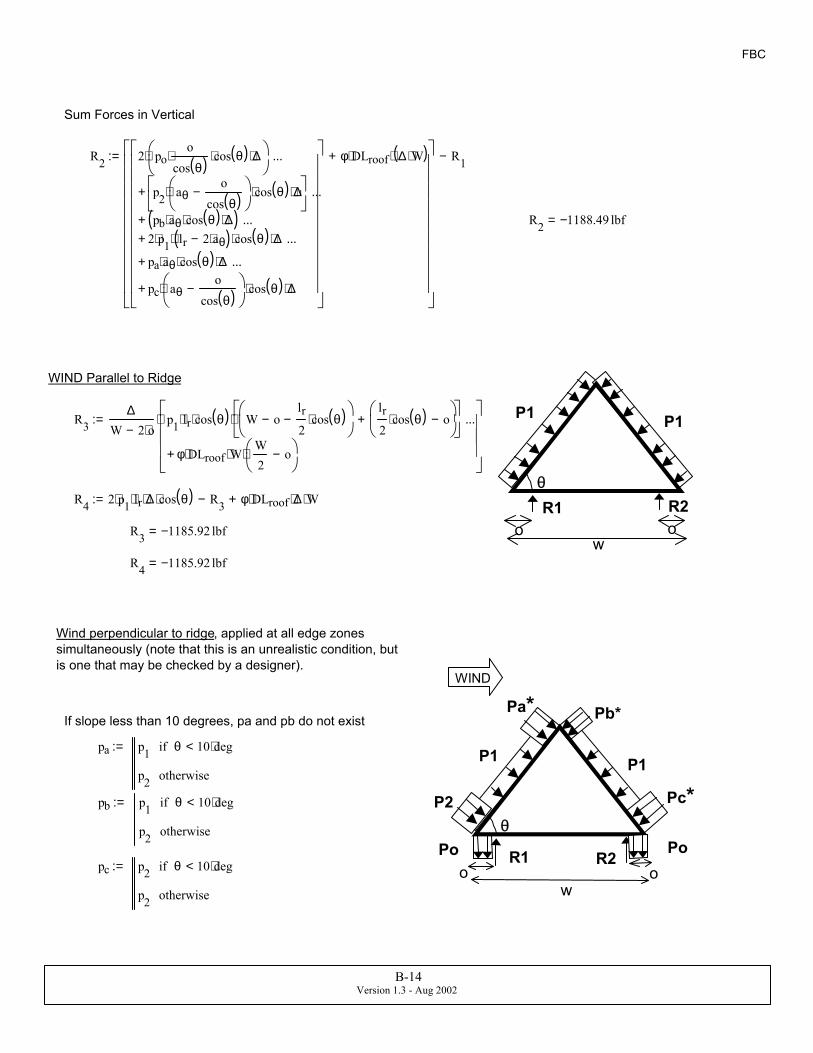
Sum Forces in Vertical
R2 2 poo
cos θ( )⋅ cos θ( )⋅ ∆⋅
⋅
p2 aθo
cos θ( )−
⋅ cos θ( )⋅ ∆⋅
+
...
pb aθ⋅ cos θ( )⋅ ∆⋅( )+
...
2 p1⋅ lr 2 aθ⋅−( )⋅ cos θ( )⋅ ∆⋅+...
pa aθ⋅ cos θ( )⋅ ∆⋅+
...
pc aθo
cos θ( )−
⋅ cos θ( )⋅ ∆⋅+
...
φ DLroof⋅ ∆ W⋅( )⋅+
R1−:=
R2 1188.49− lbf=
P1 P1
θR1 R2
wo o
WIND Parallel to Ridge
R3∆
W 2 o⋅−p1 lr⋅ cos θ( )⋅ W o−
lr2
cos θ( )⋅−
lr2
cos θ( )⋅ o−
+
⋅
φ DLroof⋅ W⋅W2
o−
⋅+
...
⋅:=
R4 2 p1⋅ lr⋅ ∆⋅ cos θ( )⋅ R3− φ DLroof⋅ ∆⋅ W⋅+:=
R3 1185.92− lbf=
R4 1185.92− lbf=
Wind perpendicular to ridge, applied at all edge zones simultaneously (note that this is an unrealistic condition, but is one that may be checked by a designer).
P2
Pa* Pb*
Pc*
P1 P1
θ
R1 R2
WIND
wo o
PoPo
If slope less than 10 degrees, pa and pb do not exist
pa p1 θ 10 deg⋅<if
p2 otherwise
:=
pb p1 θ 10 deg⋅<if
p2 otherwise
:=
pc p2 θ 10 deg⋅<if
p2 otherwise
:=
B-14Version 1.3 - Aug 2002

FBC
R11
W 2 o⋅−po
ocos θ( )⋅ ∆⋅ cos θ( )⋅ W o−
o2
−
⋅
p2 aθo
cos θ( )−
⋅ ∆⋅ cos θ( )⋅ W o−a o−
2− o−
⋅+
...
pb aθ⋅ ∆⋅ cos θ( )⋅W2
o−aθ
2cos θ( )⋅−
⋅+
...
pa aθ⋅ ∆⋅ cos θ( )⋅ W o− lraθ
2−
cos θ( )⋅−
⋅+
...
pc aθo
cos θ( )−
⋅ ∆⋅ cos θ( )⋅12
aθo
cos θ( )−
cos θ( )⋅
⋅
+
...
p1 lr 2 aθ⋅−( )⋅ ∆⋅ cos θ( )⋅ W o−lr2
cos θ( )⋅−
W2
o−lr2
cos θ( )⋅−
+
⋅
+
...
po−o
cos θ( )⋅ ∆⋅ cos θ( )⋅o2
⋅+
...
poo
cos θ( )⋅ ∆⋅ sin θ( )⋅o
2 cos θ( )⋅sin θ( )⋅
⋅
−+
...
p2 aθo
cos θ( )−
⋅ ∆⋅ sin θ( )⋅ aθ12
aθo
cos θ( )−
⋅−
sin θ( )⋅
⋅
−+
...
p1 lr 2 aθ⋅−( )⋅ ∆⋅ sin θ( )⋅lr2
sin θ( )⋅
⋅
−+
...
pa aθ⋅ ∆⋅ sin θ( )⋅ lraθ
2−
⋅ sin θ( )
−+
...
poo
cos θ( )⋅ ∆⋅ sin θ( )⋅o
2 cos θ( )⋅sin θ( )⋅
⋅+
...
p1 lr 2 aθ⋅−( )⋅ ∆⋅ sin θ( )⋅lr2
sin θ( )⋅
⋅+
...
pb aθ⋅ ∆⋅ sin θ( )⋅ lraθ
2−
⋅ sin θ( )⋅+
...
pc aθo
cos θ( )−
⋅ ∆⋅ sin θ( )⋅ aθ12
aθo
cos θ( )−
⋅−
sin θ( )⋅
⋅+
...
φ DLroof⋅ ∆⋅ W⋅W2
o−
⋅+
...
⋅:=
p2 43.39− psf=
p1 36.61− psf=
po 37.69− psf=
pa 36.61− psf=
pb 36.61− psf=
pc 43.39− psf=
aθ 3.8 ft=
W 38 ft=
lr 19 ft=
∆ 2ft=
R1 1237.44− lbf=
R2 2 poo
cos θ( )⋅ cos θ( )⋅ ∆⋅
⋅
p2 aθo
cos θ( )−
⋅ cos θ( )⋅ ∆⋅
+
...
pb aθ⋅ cos θ( )⋅ ∆⋅( )+
...
2 p1⋅ lr 2 aθ⋅−( )⋅ cos θ( )⋅ ∆⋅+...
pa aθ⋅ cos θ( )⋅ ∆⋅( )+
...
pc aθo
cos θ( )−
⋅ cos θ( )⋅ ∆⋅+
...
φ DLroof⋅ ∆ W⋅( )⋅+
R1−:=
R2 1237.44− lbf=
B-15Version 1.3 - Aug 2002
FBC
RU2774.96−
277.5−
lbf=
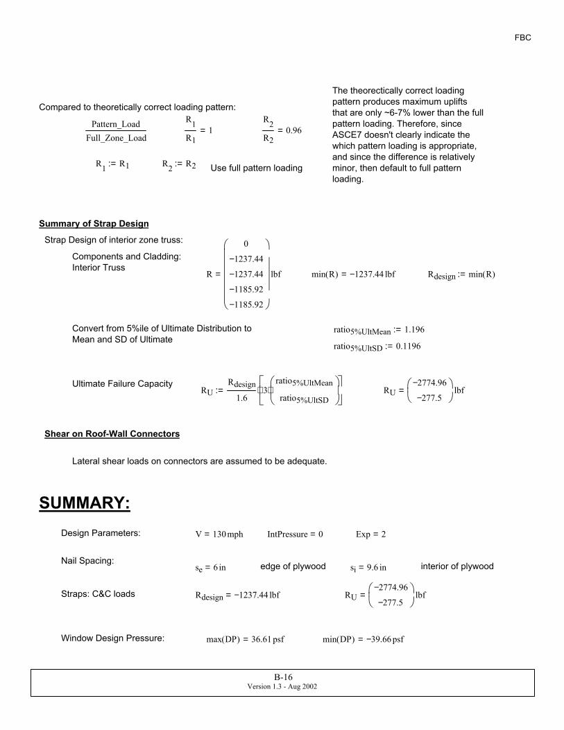
Shear on Roof-Wall Connectors
Lateral shear loads on connectors are assumed to be adequate.
SUMMARY:Design Parameters: V 130mph= IntPressure 0= Exp 2=
Nail Spacing:se 6 in= edge of plywood si 9.6 in= interior of plywood
Straps: C&C loads Rdesign 1237.44− lbf= RU2774.96−
277.5−
lbf=
Window Design Pressure: max DP( ) 36.61 psf= min DP( ) 39.66− psf=
The theorectically correct loading pattern produces maximum uplifts that are only ~6-7% lower than the full pattern loading. Therefore, since ASCE7 doesn't clearly indicate the which pattern loading is appropriate, and since the difference is relatively minor, then default to full pattern loading.
Compared to theoretically correct loading pattern:
Pattern_LoadFull_Zone_Load
R1
R11=
R2
R20.96=
R1 R1:= R2 R2:= Use full pattern loading
Summary of Strap Design
Strap Design of interior zone truss:
Components and Cladding: Interior Truss
R
0
1237.44−
1237.44−
1185.92−
1185.92−
lbf= min R( ) 1237.44− lbf= Rdesign min R( ):=
Convert from 5%ile of Ultimate Distribution to Mean and SD of Ultimate
ratio5%UltMean 1.196:=
ratio5%UltSD 0.1196:=
Ultimate Failure CapacityRU
Rdesign
1.63
ratio5%UltMean
ratio5%UltSD
⋅
⋅:=
B-16Version 1.3 - Aug 2002

SBC 88
L 192ft 2 o⋅+:=
∆ 24 in⋅:= Truss spacing
Roof cover: Shingle
hwall 9 ft⋅:= Height of Wall, single story
Dead load of roof
DLroof 9 psf⋅:= Hip roof, Tile, trusses, underlayment (from SBC Appendix A)
DLsheath 0.5 in⋅( )0.4psf.125 in⋅
⋅:= DLsheath 1.6 psf=
Dead load of 17 psf is composed of following: Truss/Sheathing (7 psf), Tile (10psf). If shingles are used, use 2 psf instead of 10 psf.
Lattic 30 psf⋅:= SBC Table 1604.1
Lfloor 40 psf⋅:=
Lroof 16 psf⋅:=
Wood Frame wall weightMasonry Wall Weight
Miscellaneous: Contents, carpet, cabinets, fixtures)DLwall
10
55
psf⋅:= DLmisc 15 psf⋅:=
SBC88 Wind Loads by SBC 1988 version
Design Parameters Variables for Enclosed/Part Encl.
in0 110 1 Enclosed( ):= Enclosed 0≡
PartEnclosed 1≡
V in0 0⟨ ⟩ mph⋅:= V 110mph=
Geometry of Building: Building Name: 0023 - condo project
h22.18 22.18+
2
ft⋅:= ht of building
IntPressure in0 2⟨ ⟩:=θ atan
012
:= θ 0deg=
o 0.0 ft⋅:= overhang widthog 0 ft⋅:=
W 38ft 2 o⋅+:= dimensions of building
B-17Version 1.3 - Aug 2002

SBC 88
dummy value
GCpi0
0
=GCpi0
0
IntPressure Enclosed=if
0.4−
0.1
IntPressure PartEnclosed=if
20−
20
otherwise
:=
Internal Pressure coefficient
length of top chord of trusslr 19 ft=lrW
2 cos θ( )⋅:=
aθ 3.8 ft=
length of edge zones along roof slope - assume that "z" in Figures 1205 are widths in plan not along roof
aθa
cos θ( ):=
a 3.8 ft=a max
a
0.04 LeastHorDim⋅
3 ft⋅
:=a 3.8 ft=a min
0.1 LeastHorDim⋅
0.4 h⋅
:=
h 22.18 ft=LeastHorDim 38 ft=LeastHorDim minW
L
:=Edge zone
qh 28.415 psf=
Dynamic Wind Pressure( Table 1606.2A)qh .00256 V2⋅h
30 ft⋅
2
7⋅
slug
2.15111 ft3⋅⋅
h hmin>( )if
.00256 V2⋅15 ft⋅30ft
2
7⋅
slug
2.15111 ft3⋅⋅ otherwise
:=
hmin 15 ft⋅:=
Dynamic Wind Pressure
B-18Version 1.3 - Aug 2002
SBC 88
Zone c, overhang
Zone c, overhangZone s, overhang
Zone s, overhang
Zone r, overhangZone r, overhangZone e
Zone wAlim_10deg
10 100 1000( )
10 100 1000( )
63 100 1000( )
63 100 1000( )
10 100 1000( )
10 500 1000( )
10 500 1000( )
10 100 1000( )
48 72 1000( )
10 100 1000( )
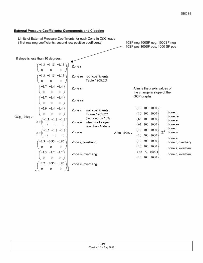
ft2⋅:=Zone eZone cZone seZone w Zone siZone re GCp_10deg
1.3−
0
1.15−
0
1.15−
0
1.3−
0
1.15−
0
1.15−
0
1.7−
0
1.4−
0
1.4−
0
1.7−
0
1.4−
0
1.4−
0
2.9−
0
1.4−
0
1.4−
0
0.91.3−
1.3
1.1−
1.0
1.1−
1.0
⋅
0.91.5−
1.3
1.1−
1.0
1.1−
1.0
⋅
1.3−
0
0.95−
0
0.95−
0
1.5−
0
1.2−
0
1.2−
0
2.7−
0
0.95−
0
0.95−
0
:=Zone r wall coefficients,
Figure 1205.2C (reduced by 10% when roof slope less than 10deg)
Zone c
Zone se
Alim is the x axis values of the change in slope of the GCP graphs
Zone si
roof coefficients Table 1205.2D
Zone re
Zone r
If slope is less than 10 degrees:
10SF neg 100SF neg, 1000SF neg10SF pos 100SF pos, 1000 SF pos
Limits of External Pressure Coefficients for each Zone in C&C loads( first row neg coefficients, second row positive coefficents)
External Pressure Coefficients: Components and Cladding
B-19Version 1.3 - Aug 2002
SBC 88
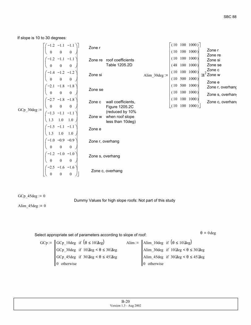
Zone c wall coefficients, Figure 1205.2C (reduced by 10% when roof slope less than 10deg)
Zone c, overhang
GCp_30deg
1.2−
0
1.1−
0
1.1−
0
1.2−
0
1.1−
0
1.1−
0
1.4−
0
1.2−
0
1.2−
0
2.1−
0
1.8−
0
1.8−
0
2.7−
0
1.8−
0
1.8−
0
1.3−
1.3
1.1−
1.0
1.1−
1.0
1.5−
1.3
1.1−
1.0
1.1−
1.0
1.0−
0
0.9−
0
0.9−
0
1.2−
0
1.0−
0
1.0−
0
2.5−
0
1.6−
0
1.6−
0
:=
Zone w
Zone e
Zone r, overhang
Zone s, overhang
Zone c, overhang
GCp_45deg 0:=Dummy Values for high slope roofs: Not part of this study
Alim_45deg 0:=
θ 0deg=Select appropriate set of parameters according to slope of roof:
GCp GCp_10deg θ 10 deg⋅≤( )if
GCp_30deg 10 deg⋅ θ< 30 deg⋅≤if
GCp_45deg 30 deg⋅ θ< 45 deg⋅≤if
0 otherwise
:= Alim Alim_10deg θ 10 deg⋅≤( )if
Alim_30deg 10 deg⋅ θ< 30 deg⋅≤if
Alim_45deg 30 deg⋅ θ< 45 deg⋅≤if
0 otherwise
:=
If slope is 10 to 30 degrees:
Zone r Zone r Zone re
Zone re roof coefficients Table 1205.2D
Zone siZone seZone c
Zone si Alim_30deg
10 100 1000( )
10 100 1000( )
10 100 1000( )
48 100 1000( )
10 100 1000( )
10 500 1000( )
10 500 1000( )
10 100 1000( )
10 100 1000( )
10 100 1000( )
ft2⋅:= Zone w
Zone eZone r, overhangZone seZone s, overhang
B-20Version 1.3 - Aug 2002
SBC 88
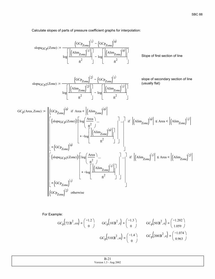
Calculate slopes of parts of pressure coefficient graphs for interpolation:
slopeGCp Zone( )GCpZone( ) 1⟨ ⟩ GCpZone( ) 0⟨ ⟩−
logAlimZone( ) 1⟨ ⟩
ft2
logAlimZone( ) 0⟨ ⟩
ft2
−
:=
Slope of first section of line
slope of secondary section of line (usually flat)slopeGCp2 Zone( )
GCpZone( ) 2⟨ ⟩ GCpZone( ) 1⟨ ⟩−
logAlimZone( ) 2⟨ ⟩
ft2
logAlimZone( ) 1⟨ ⟩
ft2
−
:=
GCp Area Zone,( ) GCpZone( ) 0⟨ ⟩ Area AlimZone( ) 0⟨ ⟩<if
slopeGCp Zone( )( ) logArea
ft2
logAlimZone( ) 0⟨ ⟩
ft2
−+
...
⋅
GCpZone( ) 0⟨ ⟩+
...
AlimZone( ) 0⟨ ⟩ Area≤ AlimZone( ) 1⟨ ⟩<if
slopeGCp2 Zone( )( ) logArea
ft2
logAlimZone( ) 1⟨ ⟩
ft2
−+
...
⋅
GCpZone( ) 1⟨ ⟩+
...
AlimZone( ) 1⟨ ⟩ Area≤ AlimZone( ) 2⟨ ⟩<if
GCpZone( ) 2⟨ ⟩ otherwise
:=
For Example:
GCp 72 ft2⋅ co,( ) 1.2−
0
= GCp 10 ft2⋅ r,( ) 1.3−
0
= GCp 50 ft2⋅ e,( ) 1.202−
1.059
=
GCp 200 ft2⋅ e,( ) 1.074−
0.963
=GCp 510 ft2⋅ si,( ) 1.4−
0
=
B-21Version 1.3 - Aug 2002
SBC 88
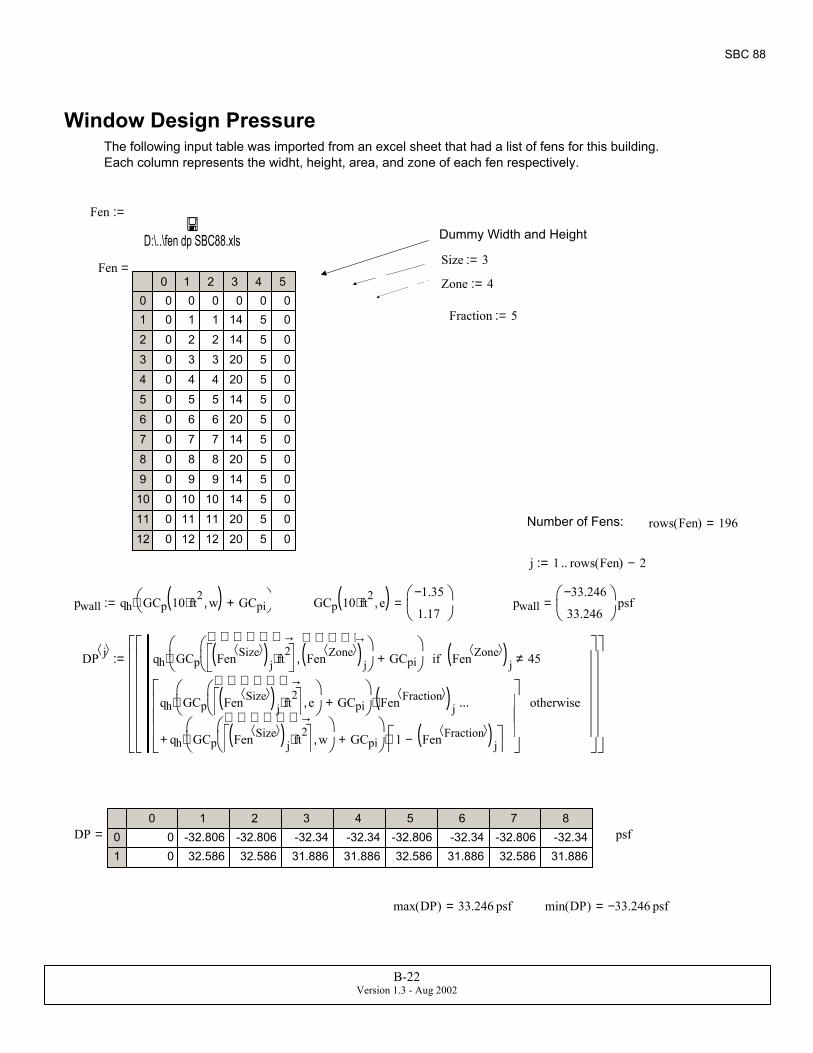
min DP( ) 33.246− psf=max DP( ) 33.246 psf=
DP0 1 2 3 4 5 6 7 8
01
0 -32.806 -32.806 -32.34 -32.34 -32.806 -32.34 -32.806 -32.340 32.586 32.586 31.886 31.886 32.586 31.886 32.586 31.886
psf=
DP j⟨ ⟩ qh GCp Fen Size⟨ ⟩( )j ft2⋅
→
Fen Zone⟨ ⟩( )j
→ ,
GCpi+
⋅ Fen Zone⟨ ⟩( )
j 45≠if
qh GCp Fen Size⟨ ⟩( )j ft2⋅
→
e,
GCpi+
⋅ Fen Fraction⟨ ⟩( )
j⋅
qh GCp Fen Size⟨ ⟩( )j ft2⋅
→
w,
GCpi+
⋅ 1 Fen Fraction⟨ ⟩( )
j−
⋅+
...
otherwise
:=
pwall33.246−
33.246
psf=GCp 10 ft2⋅ e,( ) 1.35−
1.17
=pwall qh GCp 10 ft2⋅ w,( ) GCpi+
⋅:=
j 1 rows Fen( ) 2−..:=
rows Fen( ) 196=Number of Fens:
Fraction 5:=
Zone 4:=Fen
0 1 2 3 4 50123456789101112
0 0 0 0 0 00 1 1 14 5 00 2 2 14 5 00 3 3 20 5 00 4 4 20 5 00 5 5 14 5 00 6 6 20 5 00 7 7 14 5 00 8 8 20 5 00 9 9 14 5 00 10 10 14 5 00 11 11 20 5 00 12 12 20 5 0
= Size 3:=
Dummy Width and Height
Fen
D:\..\fen dp SBC88.xls
:=
The following input table was imported from an excel sheet that had a list of fens for this building. Each column represents the widht, height, area, and zone of each fen respectively.
Window Design Pressure
B-22Version 1.3 - Aug 2002

SBC 88
t .5 in⋅:= Plywood thickness = 1/2" (min thickness of code)
lp lnail t−:= lp 1.5 in= penetration length
CD 1.6:= Duration factor for short term loads - wind = 10 minutes
Cm 1.0:= Condition Factor = assume that wood moisture content at time of construction is same as long term value
Rnail0qr lp⋅ CD⋅ Cm⋅:=
8d common nail
lnail 2.5in:= length of nail, 8d, Southern Pine (SG=0.55), NDS 97-S Table 12.2Aqr 41
lbfin
⋅:=t .5 in⋅:= Plywood thickness = 1/2" (min thickness of code)
lp lnail t−:= lp 2 in= penetration length
Resistance of single Nail, 6d and 8d respectivelyRnail1
qr lp⋅ CD⋅ Cm⋅:= Rnail84
131.2
lbf=
Design of Nailing Pattern for Roof DeckLoad on one nail: use 10 SF as effective area
Area 10 ft2⋅:= GCp Area r,( )1.3−
0
= GCp Area si,( )1.7−
0
= GCp Area c,( )2.9−
0
=
Design Load: Zone si
psingle qh GCp Area si,( ) GCpi+( )⋅:= psingle48.306−
0
psf=
Tributary Area of single sheet of plwood: (4ftx8ft)
Area 32 ft2⋅:= GCp Area r,( )1.224−
0
= GCp Area si,( )1.7−
0
= GCp Area c,( )2.142−
0
=
ppanel qh GCp Area si,( ) GCpi+( )⋅:= ppanel48.306−
0
psf=
Resistance of Single Nail
6d common nail
qr 35lbfin
⋅:= 6d common nail, Southern Pine (specifig gravtiy =0.55) NDS 1997-S Table 12.2A
lnail 2.0in:= length of nail, 6d
B-23Version 1.3 - Aug 2002
SBC 88
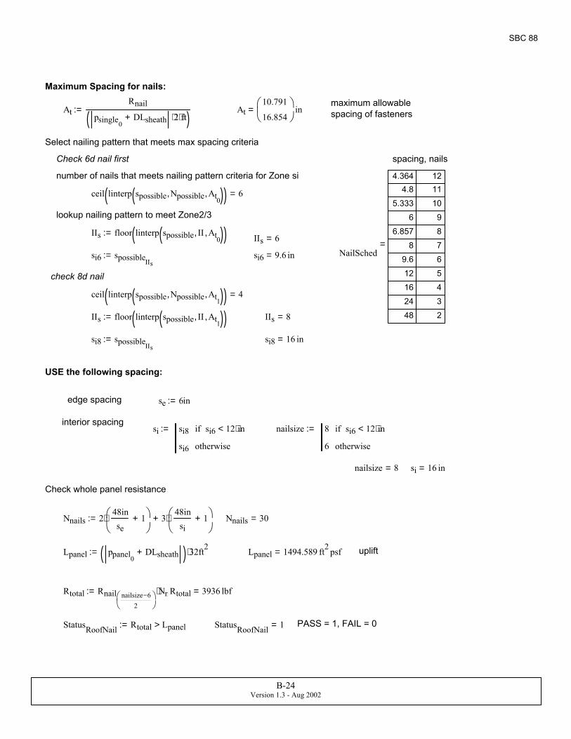
USE the following spacing:
edge spacing se 6in:=
interior spacingsi si8 si6 12 in⋅<if
si6 otherwise
:= nailsize 8 si6 12 in⋅<if
6 otherwise
:=
nailsize 8= si 16 in=
Check whole panel resistance
Nnails 248inse
1+
⋅ 348in
si1+
⋅+:= Nnails 30=
Lpanel ppanel0DLsheath+( ) 32⋅ ft2:= Lpanel 1494.589 ft2 psf= uplift
Rtotal Rnail nailsize 6−2
Nnails⋅:= Rtotal 3936 lbf=
StatusRoofNail Rtotal Lpanel>:= StatusRoofNail 1= PASS = 1, FAIL = 0
Maximum Spacing for nails:
maximum allowable spacing of fastenersAt
Rnail
psingle0DLsheath+ 2⋅ ft⋅( )
:= At10.791
16.854
in=
Select nailing pattern that meets max spacing criteria
Check 6d nail first spacing, nails
number of nails that meets nailing pattern criteria for Zone si
ceil linterp spossible Npossible, At0,( )( ) 6=
lookup nailing pattern to meet Zone2/3
IIs floor linterp spossible II, At0,( )( ):= IIs 6=
NailSched
4.364 124.8 11
5.333 106 9
6.857 88 7
9.6 612 516 424 348 2
=si6 spossibleIIs
:= si6 9.6 in=
check 8d nail
ceil linterp spossible Npossible, At1,( )( ) 4=
IIs floor linterp spossible II, At1,( )( ):= IIs 8=
si8 spossibleIIs:= si8 16 in=
B-24Version 1.3 - Aug 2002
SBC 88
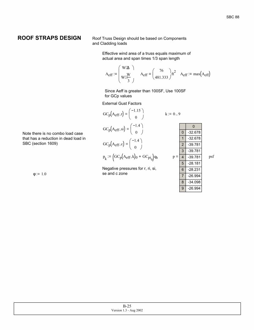
φ 1.0:=Negative pressures for r, ri, si, se and c zone
p
00123456789
-32.678-32.678-39.781-39.781-39.781-28.181-28.231-26.994-34.098-26.994
psf=pk GCp Aeff k,( )0 GCpi0+( )qh:=
GCp Aeff c,( ) 1.4−
0
=
Note there is no combo load case that has a reduction in dead load in SBC (section 1609)
GCp Aeff si,( ) 1.4−
0
=
k 0 9..:=GCp Aeff r,( ) 1.15−
0
=
External Gust Factors
Since Aeff is greater than 100SF, Use 100SF for GCp values
Aeff max Aeff( ):=Aeff76
481.333
ft2=Aeff
W ∆⋅
WW3
⋅
:=
Effective wind area of a truss equals maximum of actual area and span times 1/3 span length
Roof Truss Design should be based on Components and Cladding loads
ROOF STRAPS DESIGN
B-25Version 1.3 - Aug 2002
SBC 88
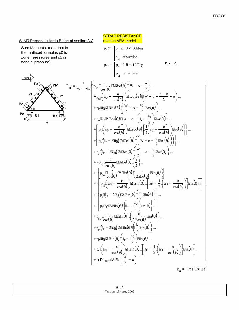
STRAP RESISTANCE used in ARA modelWIND Perpendicular to Ridge at section A-A
Sum Moments (note that in the mathcad formulas p0 is zone r pressures and p2 is zone si pressure)
pa pr θ 10 deg⋅<if
psi otherwise
:=
pc pr:=pb pr θ 10 deg⋅<if
psi otherwise
:=
P2
Pa* Pb*
Pc*
P1 P1
θ
R1 R2
WIND
wo o
PoPo
R01
W 2 o⋅−pso
ocos θ( )⋅ ∆⋅ cos θ( )⋅ W o−
o2
−
⋅
psi aθo
cos θ( )−
⋅ ∆⋅ cos θ( )⋅ W o−a o−
2− o−
⋅+
...
pb aθ⋅ ∆⋅ cos θ( )⋅W2
o−aθ
2cos θ( )⋅−
⋅+
...
pa aθ⋅ ∆⋅ cos θ( )⋅ W o− lraθ
2−
cos θ( )⋅−
⋅+
...
pc aθo
cos θ( )−
⋅ ∆⋅ cos θ( )⋅12
aθo
cos θ( )−
cos θ( )⋅
⋅
+
...
pr lr 2 aθ⋅−( )⋅ ∆⋅ cos θ( )⋅ W o−lr2
cos θ( )⋅−
⋅
+
...
pr lr 2 aθ⋅−( )⋅ ∆⋅ cos θ( )⋅W2
o−lr2
cos θ( )⋅−
⋅+
...
pso−o
cos θ( )⋅ ∆⋅ cos θ( )⋅o2
⋅+
...
psoo
cos θ( )⋅ ∆⋅ sin θ( )⋅o
2 cos θ( )⋅sin θ( )⋅
⋅
−+
...
psi aθo
cos θ( )−
⋅ ∆⋅ sin θ( )⋅ aθ12
aθo
cos θ( )−
⋅−
sin θ( )⋅
⋅
−+
...
pr lr 2 aθ⋅−( )⋅ ∆⋅ sin θ( )⋅lr2
sin θ( )⋅
⋅
−+
...
pa aθ⋅ ∆⋅ sin θ( )⋅ lraθ
2−
⋅ sin θ( )
−+
...
psoo
cos θ( )⋅ ∆⋅ sin θ( )⋅o
2 cos θ( )⋅sin θ( )⋅
⋅+
...
pr lr 2 aθ⋅−( )⋅ ∆⋅ sin θ( )⋅lr2
sin θ( )⋅
⋅+
...
pb aθ⋅ ∆⋅ sin θ( )⋅ lraθ
2−
⋅ sin θ( )⋅+
...
pc aθo
cos θ( )−
⋅ ∆⋅ sin θ( )⋅ aθ12
aθo
cos θ( )−
⋅−
sin θ( )⋅
⋅+
...
φ DLroof⋅ ∆⋅ W⋅W2
o−
⋅+
...
⋅:=
R0 951.036− lbf=
B-26Version 1.3 - Aug 2002
SBC 88
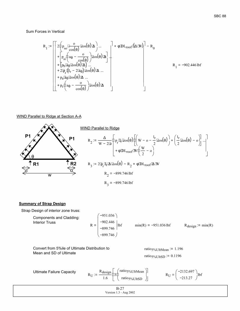
RU2132.697−
213.27−
lbf=RURdesign
1.63
ratio5%UltMean
ratio5%UltSD
⋅
⋅:=Ultimate Failure Capacity
ratio5%UltSD 0.1196:=
ratio5%UltMean 1.196:=Convert from 5%ile of Ultimate Distribution to Mean and SD of Ultimate
Rdesign min R( ):=min R( ) 951.036− lbf=R
951.036−
902.446−
899.746−
899.746−
lbf=
Components and Cladding: Interior Truss
Strap Design of interior zone truss:
Summary of Strap Design
R3 899.746− lbf=
R2 899.746− lbf=
R3 2 pr⋅ lr⋅ ∆⋅ cos θ( )⋅ R2− φ DLroof⋅ ∆⋅ W⋅+:=
R2∆
W 2 o⋅−pr lr⋅ cos θ( )⋅ W o−
lr2
cos θ( )⋅−
lr2
cos θ( )⋅ o−
+
⋅
φ DLroof⋅ W⋅W2
o−
⋅+
...
⋅:=
WIND Parallel to Ridge
P1 P1
θR1 R2
wo o
WIND Parallel to Ridge at Section A-A
R1 902.446− lbf=
R1 2 psoo
cos θ( )⋅ cos θ( )⋅ ∆⋅
⋅
psi aθo
cos θ( )−
⋅ cos θ( )⋅ ∆⋅
+
...
pb aθ⋅ cos θ( )⋅ ∆⋅( )+
...
2 pr⋅ lr 2 aθ⋅−( )⋅ cos θ( )⋅ ∆⋅+...
pa aθ⋅ cos θ( )⋅ ∆⋅+
...
pc aθo
cos θ( )−
⋅ cos θ( )⋅ ∆⋅+
...
φ DLroof⋅ ∆ W⋅( )⋅+
R0−:=
Sum Forces in Vertical
B-27Version 1.3 - Aug 2002

SBC 88
SUMMARY:Design Parameters: V 110mph= IntPressure 0=
Nail Spacing:nailsize 8= se 6 in= edge of plywood si 16 in= interior of plywood
Straps: C&C loads Rdesign 951.036− lbf= RU2132.697−
213.27−
lbf=
Window Design Pressure: max DP( ) 33.246 psf= min DP( ) 33.246− psf=
B-28Version 1.3 - Aug 2002

SBC 76
dimensions of buildingL 192ft 2 o⋅+:=Use 1.0:=∆ 24 in⋅:= Truss spacing
Roof cover: Shingle
hwall 9 ft⋅:= Height of Wall, single story
Dead load of roof
DLroof 9 psf⋅:= Hip roof, Tile, trusses, underlayment (from SBC Appendix A)
DLsheath 0.5 in⋅( )0.4psf.125 in⋅
⋅:= DLsheath 1.6 psf=
Dead load of 17 psf is composed of following: Truss/Sheathing (7 psf), Tile (10psf). If shingles are used, use 2 psf instead of 10 psf.
Lattic 30 psf⋅:= SBC Table 1604.1
Lfloor 40 psf⋅:=
Lroof 16 psf⋅:=
Wood Frame wall weightMasonry Wall Weight
Miscellaneous: Contents, carpet, cabinets, fixtures)DLwall
10
55
psf⋅:= DLmisc 15 psf⋅:=
Wind Loads by SBC 1976 versionSBC 76
Variables for Enclosed/Part Encl.
Design ParametersEnclosed 0≡
PartEnclosed 1≡in0 110 Enclosed 0( ):=
V in0 0⟨ ⟩ mph⋅:=
Geometry of Building: Building Name: 0023 - condo projectV 110mph=
h22.18 22.18+
2
ft⋅:= ht of building
IntPressure in0 2⟨ ⟩:=
θ atan012
:= θ 0deg=IntPressure 0=o 0.0 ft⋅:= overhang width
og 0 ft⋅:=
W 38ft 2 o⋅+:=Table 1606: Use factor
B-29Version 1.3 - Aug 2002
SBC 76
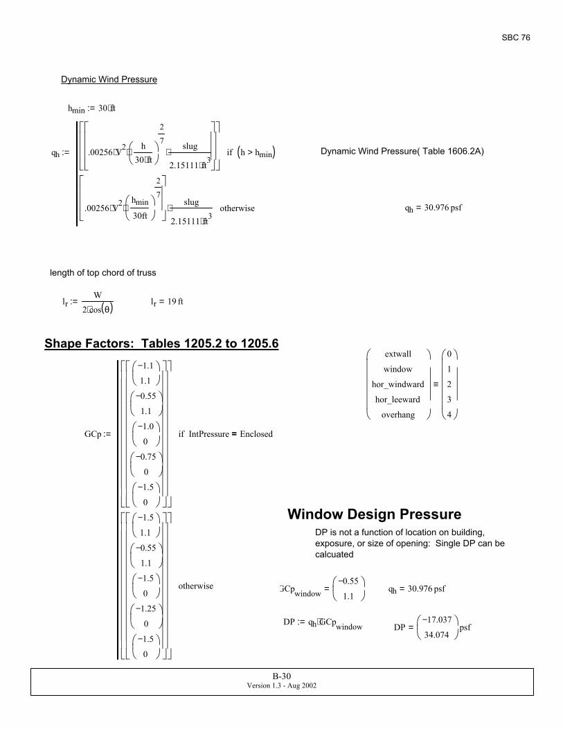
DP17.037−
34.074
psf=DP qh GCpwindow⋅:=
qh 30.976 psf=GCpwindow0.55−
1.1
=
DP is not a function of location on building, exposure, or size of opening: Single DP can be calcuated
Window Design Pressure
GCp
1.1−
1.1
0.55−
1.1
1.0−
0
0.75−
0
1.5−
0
IntPressure Enclosed=if
1.5−
1.1
0.55−
1.1
1.5−
0
1.25−
0
1.5−
0
otherwise
:=
extwall
window
hor_windward
hor_leeward
overhang
0
1
2
3
4
≡
Shape Factors: Tables 1205.2 to 1205.6
lr 19 ft=lrW
2 cos θ( )⋅:=
length of top chord of truss
qh 30.976 psf=
Dynamic Wind Pressure( Table 1606.2A)qh .00256 V2⋅h
30 ft⋅
2
7⋅
slug
2.15111 ft3⋅⋅
h hmin>( )if
.00256 V2⋅hmin
30ft
2
7
⋅
slug
2.15111 ft3⋅⋅ otherwise
:=
hmin 30 ft⋅:=
Dynamic Wind Pressure
B-30Version 1.3 - Aug 2002
SBC 76
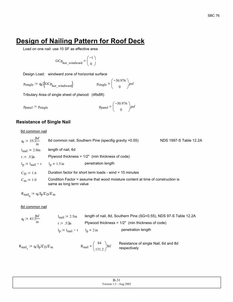
penetration length
CD 1.6:= Duration factor for short term loads - wind = 10 minutes
Cm 1.0:= Condition Factor = assume that wood moisture content at time of construction is same as long term value
Rnail0qr lp⋅ CD⋅ Cm⋅:=
8d common nail
lnail 2.5in:= length of nail, 8d, Southern Pine (SG=0.55), NDS 97-S Table 12.2Aqr 41
lbfin
⋅:=t .5 in⋅:= Plywood thickness = 1/2" (min thickness of code)
lp lnail t−:= lp 2 in= penetration length
Resistance of single Nail, 6d and 8d respectivelyRnail1
qr lp⋅ CD⋅ Cm⋅:= Rnail84
131.2
lbf=
Design of Nailing Pattern for Roof DeckLoad on one nail: use 10 SF as effective area
GCphor_windward1−
0
=
Design Load: windward zone of horizontal surface
psingle qh GCphor_windward( )⋅:= psingle30.976−
0
psf=
Tributary Area of single sheet of plwood: (4ftx8ft)
ppanel psingle:= ppanel30.976−
0
psf=
Resistance of Single Nail
6d common nail
qr 35lbfin
⋅:= 6d common nail, Southern Pine (specifig gravtiy =0.55) NDS 1997-S Table 12.2A
lnail 2.0in:= length of nail, 6d
t .5 in⋅:= Plywood thickness = 1/2" (min thickness of code)
lp lnail t−:= lp 1.5 in=
B-31Version 1.3 - Aug 2002

SBC 76
edge spacing se 6in:=
interior spacingsi si8 si6 12 in⋅<if
si6 otherwise
:= nailsize 8 si6 12 in⋅<if
6 otherwise
:=
nailsize 6= si 16 in=
Spacing cannot exceed 12 inches: si min si 12 in⋅,( ):= si 12 in=
Check whole panel resistance
Nnails 248inse
1+
⋅ 348in
si1+
⋅+:= Nnails 33=
Lpanel ppanel0DLsheath+( ) 32⋅ ft2:= Lpanel 940.033 ft2 psf= uplift
Rtotal Rnail nailsize 6−2
Nnails⋅:= Rtotal 2772 lbf=
StatusRoofNail Rtotal Lpanel>:= StatusRoofNail 1= PASS = 1, FAIL = 0
Maximum Spacing for nails:
maximum allowable spacing of fastenersAt
Rnail
psingle0DLsheath+ 2⋅ ft⋅( )
:= At17.157
26.797
in=
Select nailing pattern that meets max spacing criteria
Check 6d nail first spacing, nails
number of nails that meets nailing pattern criteria for Zone si
ceil linterp spossible Npossible, At0,( )( ) 4=
lookup nailing pattern to meet Zone2/3
IIs floor linterp spossible II, At0,( )( ):= IIs 8=
NailSched
4.364 124.8 11
5.333 106 9
6.857 88 7
9.6 612 516 424 348 2
=si6 spossibleIIs
:= si6 16 in=
check 8d nail
ceil linterp spossible Npossible, At1,( )( ) 3=
IIs floor linterp spossible II, At1,( )( ):= IIs 9=
si8 spossibleIIs:= si8 24 in=
USE the following spacing:
B-32Version 1.3 - Aug 2002

SBC 76
R1687.513−
228
lbf=
R1 ∆ phor_windwardW
3 cos θ( )⋅⋅ cos θ( )⋅ phor_leeward( ) 2 W⋅
3 cos θ( )⋅
⋅ cos θ( )⋅+
⋅ R0− φ DLroof⋅ ∆⋅ W⋅+
:=
Sum Forces in Vertical
R0818.301−
228
lbf=
P2
Pa* P2
Pa*
P1 P1
θ
R1 R2
WIND
wo o
PoPo
R0∆
W 2 o⋅−( )phor_windward
W3 cos θ( )⋅
⋅ cos θ( )⋅ W o−W3
0.5⋅−
⋅
phor_leeward lrW
3 cos θ( )⋅−
⋅ cos θ( )⋅ W o−W3
−W12
−
⋅+
...
phor_leeward lr( )⋅ cos θ( )⋅W4
o−
⋅+
...
phor_windward−W
3 cos θ( )⋅
⋅ sin θ( )⋅W
3 cos θ( )⋅sin θ( )
2⋅
⋅+
...
phor_leeward− lrW
3 cos θ( )⋅−
⋅ sin θ( )⋅ lrW
12 cos θ( )⋅−
sin θ( )⋅
⋅+
...
phor_leeward lr( )⋅ sin θ( )⋅lr2
⋅ sin θ( )⋅+
...
φ DLroof⋅ W⋅W2
o−
⋅+
...
⋅:=Sum Moments (note that in the mathcad formulas p0 is zone r pressures and p2 is zone si pressure)
WIND Perpendicular to Ridge at section A-ASTRAP RESISTANCE used in ARA model
φ23
:=
phor_leeward23.232−
0
psf=
phor_leeward qh GCphor_leeward⋅:= phor_windward30.976−
0
psf=
phor_windward qh GCphor_windward⋅:=Section 1205.3: StabilityIndicates: (c) the uplift forces calculation from wind pressure shall not exceed two-thirds of the resisting dead load.
This is interpreted as limiting Dead load contribution to 67%
GCphor_leeward0.75−
0
=
k 0 4..:=GCphor_windward1−
0
=External Gust Factors
Roof Truss Design should be based on Components and Cladding loads from Table 1205.5 which refers to Table 1205.3
ROOF STRAPS DESIGN
B-33Version 1.3 - Aug 2002
SBC 76
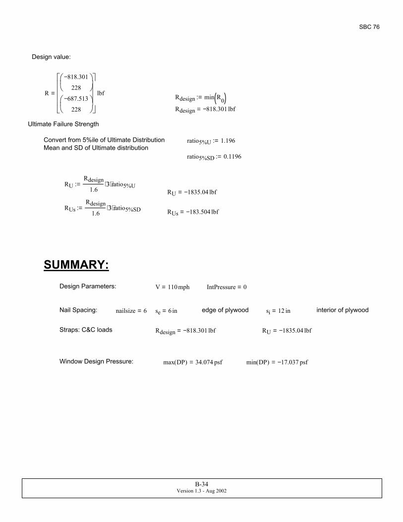
min DP( ) 17.037− psf=max DP( ) 34.074 psf=Window Design Pressure:
RU 1835.04− lbf=Rdesign 818.301− lbf=Straps: C&C loads
interior of plywoodsi 12 in=edge of plywoodse 6 in=nailsize 6=Nail Spacing:
IntPressure 0=V 110mph=Design Parameters:
SUMMARY:
RUs 183.504− lbf=RUsRdesign
1.63⋅ ratio5%SD⋅:=
RU 1835.04− lbf=RU
Rdesign
1.63⋅ ratio5%U⋅:=
ratio5%SD 0.1196:=
ratio5%U 1.196:=Convert from 5%ile of Ultimate Distribution Mean and SD of Ultimate distribution
Ultimate Failure Strength
Rdesign 818.301− lbf=
Rdesign min R0( ):=R
818.301−
228
687.513−
228
lbf=
Design value:
B-34Version 1.3 - Aug 2002