lopro linear motion systems - cbm industries competition and cost cutting issues in the forefront of...
TRANSCRIPT

METRICPRODUCT OVERVIEW
LOPRO LINEARMOTION SYSTEMSLOPRO LINEARMOTION SYSTEMS
METRICPRODUCT OVERVIEWBISHOP-WISECARVER CORPORATION
T H E F U T U R E O F L I N E A R M O T I O N
OUR 50TH YEAR

Product Overview ................................ 1
Belt Driven Lo ProLinear Motion Systems ................... 4
Chain Driven Lo ProLinear Motion Systems ................... 6
Screw Driven Lo ProLinear Motion Systems ................... 8
Pneumatic Cylinder Driven Lo ProLinear Motion Systems ................... 10
System Dimensions .............................. 12
Drive End Dimensions .......................... 13
Product Selection ................................. 14
Sample Calculations ........................ 15
Wheel Plate Capacity vs. Speed ..... 16
System Life vs. Load ........................ 18
Lo Pro Linear Motion Systems
Wheels
V E R S A T I L E I N D E S I G N
TM
TABLE OF CONTENTS

ITH COMPETITION AND COSTcutting issues in the forefront of ourbusiness climate, the need forversatile linear motion systems is
becoming increasingly important. To meet thisneed, Bishop-Wisecarver Corporation hasdeveloped the Dual-Vee Lo Pro Linear MotionSystems. Lo Pro systems integrate our Dual-Veeprecision linear motion components into linearmotion systems. Bishop-Wisecarver Corporationis your single source for linear motioncomponents and systems.
WWW
PRODUCT OVERVIEWV E R S A T I L E I N D E S I G N
TM
11
BISHOP-WISECARVER CORPORATIONT H E F U T U R E O F L I N E A R M O T I O N
OUR 50TH YEAR
Wheel Bushings
Lo Pro systems are available in four sizeswith many drive options including belt,
chain, lead screw, and pneumatic cylinderactuator, making Lo Pro the natural selectionfor your applications. Lo Pro systems are alsoavailable without drive products. The foursystems provide a wide range of capacities fromsmall to very large loads. A Lo Pro size #4system with one wheel plate has a radial loadcapacity over 26,000 N and a thrust loadcapacity over 40,000 N at 0.125 meters/second.It can also handle speeds in excess of 12 meters/second. Our manufacturing facility can quicklyand cost effectively build your system to anylength. Quality is built into each systemthroughout manufacturing, assembly,inspection and testing.
Track Plate Assemblies
Dual-Vee components consist of guidewheels, bushings, and track, that provide
a proven, economical method of obtainingprecision linear motion for all types ofmechanical applications. Our Lo Pro systemscombine our Dual-Vee components with ourLo Pro wheel plate, track plate, drive products,drive ends, and accessories. This culminates into
Wiper Wheel Plate Assembly
DD
LL

high performing, versatile, and cost effectivelinear motion systems. The low profile design ofLo Pro systems allow multiple stacking withminimal stack-up error.
Our guide wheels are pre-lubricated, doublerow angular contact ball bearings having
ABEC 1 precision grinding. The Lo Pro systemscome standard with AISI 52100 carbon steelsealed wheels. These wheels are hardened to60 - 62 Rockwell C. Sealed bearing wheels areavailable in both AISI 52100 carbon steel andAISI 440C stainless steel. The geometry of the
22
OO
Belt Drive End
wheel provides a greater circumference at themajor diameter than at the minor diameterresulting in a constant wiping action on thetrack which has a self-cleaning effect. Thisresults in contaminants not causing a great lossof efficiency in the system.
Our standard track is cold formed from AISI1045 carbon steel. Track is also available in
AISI 420 stainless steel. The track is inductionhardened on the “V” contact surfaces. Carbonsteel track is hardened to 59 Rockwell Cminimum, and stainless steel track is hardened
OO
Wiper Wheel Plate Assembly
to 40 Rockwell C minimum. The track ismounted on 6005A aluminum extruded trackplate resulting in excellent track parallelism.The specification for track parallelism is 60.04millimeter over a 3 meter length. The trackplate is designed for quick bolt downintegration for OEM needs.
Eccentric bushings are used oppositeconcentric bushings to provide a simple and
effective means of adjusting free play in thesystem. The bushings are made from 303stainless steel. Wheel bolt and wheel bushingwrenches are available to allow easy wheel totrack adjustment. The wheel bolt wrench isdesigned to maximize the turning radius to
EE
Standard Wheel Plate Assembly
PRODUCT OVERVIEW

V E R S A T I L E I N D E S I G N
TM
33
BISHOP-WISECARVER CORPORATIONT H E F U T U R E O F L I N E A R M O T I O N
OUR 50TH YEAR
loosen and tighten the wheel bolts withminimal interference of the track plate. Thewheel bushing adjuster wrench is designed toeasily fit between the wheel and the wheelplate. The wheel bushing adjuster wrench isdesigned with a knob on the end of the handleto easily differentiate it from the wheel boltwrench.
Two different wheel plate assemblies areavailable. Both designs are made from
aluminum extrusions. They are all precisionmachined. Both the wiper wheel plate andstandard wheel plate are light weight anddesigned to allow easy work plate mounting.Our wiper version includes lubricated wipersand our standard version does not. Wipersprovide a clean lubricated surface for thewheels resulting in significantly extending trackand wheel life. The unique wiper designprovides for quick and easy lubrication andreplacement. Wiper removal and replacementcan be easily accomplished while the wheelplate remains on the track. Felt inserts arequick and easy to replace and are availableseparately.
TTWiper Assemblies
Dual-Vee Lo Pro systems are designed tominimize installation and maintenance
costs. Our components and systems quicklymount to your equipment and are cost effectiveto maintain. Wheel adjustment and wiperlubrication or replacement can be done quicklywhile the wheel plate remains on the system.If the track wears out it can be replaced bypurchasing only the track and mounting it onthe aluminum track extrusion.
DD

44
V E R S A T I L E I N D E S I G N
Wiper Wheel Plate with Belt Drive System: Lo Pro Belt driven systems available in four sizes with wiper and standard wheel plates. Small and large drive ends with multiple belt options available.
Belt Coupler: Lo Pro Belt driven systems use uniquely designed couplers. These couplers are very easy to adjust to ensure your system operates with proper belt tension.
Wheel with Concentric Bushing: AISI 52100 carbon steel shielded wheels, pre-lubricated double row angular contact ball bearings with concentric stainless steel bushings.
Wiper Wheel Plate and Track Plate System: Wiper wheel plates are aluminum extrusions with wipers. Wipers provide a clean lubricated surface for the wheels and track. Track plate system consists of carbon steel track mounted on aluminum extruded track plate.
Wipers provide a clean lubricated surface for the wheels resulting in significantly extending track and wheel life. The unique wiper design provides for quick and easy lubrication and replacement.
TM
M4ACUBA32T1
OILED - FELT
#4 WIPER BODYRIGHT HAND
3X7.32
47.96
51.33
5/H-11 LH UNC-2B
7/8-14 RH UNF-2B
41.17
M4SCWBGD32T1
W4X
M4SCW
87.00
140.00
26.49
55.00
213.10
14.02
30 T
OO
TH 3
2AT1
095
.49
mm
DIA
ME
TER
9.52
SCALE = 1.0
SECTION A-A
90.00∞
A
60.33
50.80
22.23
.0003 S A
19.05
111.00
140.00
35.75
55.00
172.72
BELT DRIVEN LOPROLINEAR MOTION SYSTEMS

The standard belt used in the Lo Pro systemsconsists of modified Trapezoidal tooth
design with metric pitch, constructed from anextremely wear resistant polyurethane with ahigh tensile braided steel tension member.
The “AT” style belt has a working capacity40% greater than the normal trapezoidal
timing belt.
The table below shows the maximumallowable belt tension (working load) and
the ultimate tensile strength of each belt drivenLo Pro system.
Lo Pro Belt driven systems are designed tominimize installation and maintenance costs.
V E R S A T I L E I N D E S I G N
TM
55
BISHOP-WISECARVER CORPORATIONT H E F U T U R E O F L I N E A R M O T I O N
OUR 50TH YEAR
BBBELT DRIVEN LO PRO LINEAR MOTIONsystems are very versatile. With fourdifferent wheel and track sizes,Lo Pro Belt driven systems have the
ability to handle a large range of performancerequirements including high loads and speeds.Belts experience no permanent elongationwithin the life of the belt. Hence it is anexcellent choice in robotic and automationapplications which require high repeatability,positional accuracy, low inertia and lowmaintenance operation. The belt elongates ina linear manner and follows Hooke’s Law. Oncethe force is removed, the belt will go back toits original length.
TT
TT
LL
TT
LO PROSYSTEMSIZE
1
2
2
3
4
DRIVEENDSIZE
Small
Small
Large
Large
Large
BELTPARTNUMBER
10AT5
16AT5
16AT10
25AT10
32AT10
WORKINGLOAD (N)
“AT” TYPE STEEL CORD
365
750
1515
2490
3185
ULTIMATE TENSILESTRENGTH (N)
2600
4100
8600
13400
17200

66
V E R S A T I L E I N D E S I G N
Standard Wheel Plate with Triple Chain Drive System: Lo Pro Chain driven systems available in four sizes with wiper and standard wheel plates. Small and large drive ends with many chain options.
Chain Coupler: Lo Pro Chain driven systems use uniquely designed couplers. These couplers are very easy to adjust to ensure your system operates with proper chain tension.
Standard Wheel Plate: Two different aluminum extruded wheel plate designs are available. The standard design (pictured above) and the wiper version. Wipers provide a clean lubricated surface for the wheels and track.
Standard Wheel Plate and Track Plate System: Standard wheel plates are aluminum extrusions without wipers. Track plate system consists of carbon steel track mounted on aluminum extruded track plate.
Eccentric Bushings: Eccentric bushings are used opposite concentric bushings to provide a simple and effective means of adjusting wheel preload in the system. The bushing material is 303 stainless steel.
CHAIN DRIVEN LOPROLINEAR MOTION SYSTEMS
TM
M4ACUCA50S
M4AWPS
M4SCS
4PBX
M4SCSCGD50S
172.80
55.00
51.86
87.00
26.50
110.75
75.00
0.625" PITCH #50SINGLE ROLLER CHAIN
3X7.32
47.96
31.11
05.16
5/8-11 LH UNC-2B
7/8-14 RH UNF-2B
22.86
W 4 WHEEL43.00
43.0066.00
66.00172.21
206.60
178.46
212.34
8X M10
X 1
.5 IS
OW
7.9
5
21.97
RO.51 MAX
22.21 NOM.
1.52±0.02
Ø9.53 +0.050.00
Ø14.99 0.00–0.023.17 0.00
–0.05
0.00–0.05
55.00
172.72
35.75
140.00
111.00

V E R S A T I L E I N D E S I G N
TM
77
BISHOP-WISECARVER CORPORATIONT H E F U T U R E O F L I N E A R M O T I O N
OUR 50TH YEAR
CCCHAIN DRIVEN LO PRO LINEARmotion systems are very versatile.With four different wheel and tracksizes, Lo Pro Chain driven systems
have the ability to handle a large range ofperformance requirements including high loadsand speeds. Roller chains are inherently elastic,they soften shock and absorb vibration. Chainsare stronger than belts and are an excellentchoice in applications which allow chainlubrication. Chains perform well in heavy shockload applications and in dirty environmentswhere contaminants can be pushed throughthe chain by the sprocket.
Chain driven Lo Pro systems use a singlestrand roller chain based on the system
size. The following table identifies thestandard chain available, the working load andthe maximum average tensile rating of eachchain driven Lo Pro system:
The working load identifies therecommended maximum chain pull.
Keeping the system loads at or below thesenumbers will minimize chain stretch andsprocket wear resulting in better systemperformance and repeatability.
Dual-Vee Lo Pro systems are designed tominimize installation and maintenance
costs. The Lo Pro components and systemsquickly mount to your equipment and are costeffective to maintain. It is important that thetrack plate is completely and firmly mounted ona support structure using all the mounting holesprovided. Wheel and coupler adjustment, andwiper lubrication or replacement can be donequickly while the wheel plate remains on thesystem. If the track wears out it can be replacedby purchasing only the track and mounting it onthe track plate.
Lo Pro Chain driven systems use uniquelydesigned couplers. These couplers are very
easy to adjust to ensure your system operateswith proper chain tension. The chain tensioncan be quickly performed with the systemcompletely assembled. Once proper adjustmentis obtained, the two lock nuts ensure theadjustment will be maintained. Adjustment canbe easily achieved without special wrenches,however wrenches are available to make chainadjustment quick and easy. The wrenches arehigh carbon steel and heat treated to 58Rockwell C.
TT
LO PROSYSTEMSIZE
1
2
2
3
4
DRIVEENDSIZE
Small
Small
Large
Large
Large
CHAINSIZE/# OFSTRANDS
WORKINGLOAD(N)
625
2135
2135
3600
6225
ULTIMATETENSILESTRENGTH(N)
3890
9340
9340
16455
27130
25 / 1
35 / 1
35 / 1
40 / 1
50 / 1
CC
DD
LL

88
V E R S A T I L E I N D E S I G N
Lead Screw Drive End: Drive end with separate radial and thrust bearings provide high efficiency and reliable performance.
Wiper for Wheel Plate: The unique wiper design provides for quick and easy lubrication and replacement.
Lead Screw: Lead screws are manufactured from 303 stain-less steel. The screw thread is designed for maximum life and quiet operation. Available with anti-backlash nut.
Wiper Wheel Plate and Track Plate System: Wiper and Standard (without wipers) aluminum extruded wheel plates available. Wiper design provides track and wheel surface lubrication.
Track Plate Assembly: The track is mounted on aluminum extruded track plate resulting in excellent track parallelism. The track plate is designed for quick bolt down integration for OEM needs.
SCREW DRIVEN LOPROLINEAR MOTION SYSTEMS
TM
25.00
Ø 12.00
35.92
1.91
54.00
THRUSTBEARINGS
RADIALBEARING
SECTION A-ASCALE = 1.00
M4ADELSC
OILED - FELT
#4 WIPER BODYRIGHT HAND
D1 D2
D3
SECTION A-ASCALE = 1.000.020 X 45 ∞
CHAMFER
DI D2 D3M1 System 5.0 12.0 44.3M2 System 6.0 20.0 59.7M3 System 12.0 25.0 70.7M4 System 12.0 25.0 70.7
14∞2X
2XR6.10
SECTION A-ASCALE = 1.00
111.00
140.00
39.37
31.00
6.70
13.84
M4ATP
M4SCWLSV
63.50
213.10
35.7555.00
140.00
111.00
50.80
Ø 12.00
V E R S A T I L E I N D E S I G N
TM
99
BISHOP-WISECARVER CORPORATIONT H E F U T U R E O F L I N E A R M O T I O N
OUR 50TH YEAR
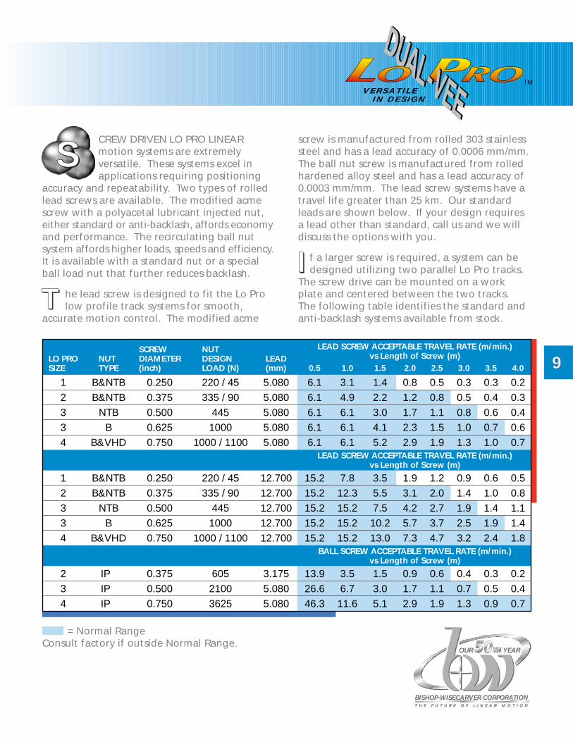
CREW DRIVEN LO PRO LINEARmotion systems are extremelyversatile. These systems excel inapplications requiring positioning
accuracy and repeatability. Two types of rolledlead screws are available. The modified acmescrew with a polyacetal lubricant injected nut,either standard or anti-backlash, affords economyand performance. The recirculating ball nutsystem affords higher loads, speeds and efficiency.It is available with a standard nut or a specialball load nut that further reduces backlash.
The lead screw is designed to fit the Lo Prolow profile track systems for smooth,
accurate motion control. The modified acme
screw is manufactured from rolled 303 stainlesssteel and has a lead accuracy of 0.0006 mm/mm.The ball nut screw is manufactured from rolledhardened alloy steel and has a lead accuracy of0.0003 mm/mm. The lead screw systems have atravel life greater than 25 km. Our standardleads are shown below. If your design requiresa lead other than standard, call us and we willdiscuss the options with you.
If a larger screw is required, a system can bedesigned utilizing two parallel Lo Pro tracks.
The screw drive can be mounted on a workplate and centered between the two tracks.The following table identifies the standard andanti-backlash systems available from stock.
TTII
LO PROSIZE
12334
12334
234
B
NUTTYPE
B&NTBB&NTB
NTB
B&VHD
B&NTBB&NTB
NTBB
B&VHD
IPIPIP
SCREWDIAMETER(inch)
0.2500.3750.5000.6250.750
0.2500.3750.5000.6250.750
0.3750.5000.750
NUTDESIGNLOAD (N)
220 / 45335 / 90
4451000
1000 / 1100
220 / 45335 / 90
4451000
1000 / 1100
60521003625
LEAD(mm)
5.0805.0805.0805.0805.080
12.70012.70012.70012.70012.700
3.1755.0805.080
0.5
LEAD SCREW ACCEPTABLE TRAVEL RATE (m/min.)vs Length of Screw (m)
LEAD SCREW ACCEPTABLE TRAVEL RATE (m/min.)vs Length of Screw (m)
BALL SCREW ACCEPTABLE TRAVEL RATE (m/min.)vs Length of Screw (m)
6.1
15.2
6.1
15.2
6.1
15.2
6.1
15.2
6.1
15.2
13.926.646.3
1.0
3.1
7.8
4.9
12.3
6.1
15.2
6.1
15.2
6.1
15.2
3.56.7
11.6
1.5
1.4
3.5
2.2
5.5
3.0
7.5
4.1
10.2
5.2
13.0
1.53.05.1
2.0
0.8
1.9
1.2
3.1
1.7
4.2
2.3
5.7
2.9
7.3
0.91.72.9
2.5
0.5
1.2
0.8
2.0
1.1
2.7
1.5
3.7
1.9
4.7
0.61.11.9
3.0
0.3
0.9
0.5
1.4
0.8
1.9
1.0
2.5
1.3
3.2
0.40.71.3
3.5
0.3
0.6
0.4
1.0
0.6
1.4
0.7
1.9
1.0
2.4
0.30.50.9
4.0
0.2
0.5
0.3
0.8
0.4
1.1
0.6
1.4
0.7
1.8
0.20.40.7
SSS
= Normal RangeConsult factory if outside Normal Range.

1010
V E R S A T I L E I N D E S I G N
Wheel with Concentric Bushing: AISI 52100 carbon steel shielded wheels, pre-lubricated double row angular contact ball bearings with concentric 303 stainless steel bushings.
Standard Wheel Plate and Track Plate System: Wiper and Standard (without wipers) aluminum extruded wheel plates available. Wiper design provides track and wheel surface lubrication.
Dual-Vee Track: AISI 1045 cold formed steel hardened to 59 Rockwell C. Track is also avail-able in AISI 420 stainless steel.
Pneumatic Cylinder Coupler Clevis Pin: Designed to easily mount cylinder piston rod to wheel plate and allows working compliance.
Pneumatic Cylinder Mount: Provides quick and secure mount for the Pneumatic Cylinder.
PNEUMATIC CYLINDER LOPROLINEAR MOTION SYSTEMS
TM
M4SCW
4KWBC
4PCUPUC
R12.9
10.2
5.8
32.1
17.5
7/8–14 UNF 2B
Ø18.8
Ø9.6
111.00
140.00
35.75
55.00
172.72
T4
9.52
SCALE = 1.0
SECTION A-A
90.00∞
A
60.33
50.80
22.23
.0003 S A
19.05
SECTION A-ASCALE = 1.0
A.0005 S
A
2.36
11.10
26.98
19.13
90.0∞
28.70 60.96
9.40
10.80
38.10
54.00
22.23
35.74
M4PDEPU31

BISHOP-WISECARVER CORPORATIONT H E F U T U R E O F L I N E A R M O T I O N
OUR 50TH YEAR
PPPNEUMATIC CYLINDER ACTUATORLo Pro linear motion systems arevery versatile. Pneumatic cylinderactuators are excellent for high
torque, high speed applications requiring ashort stroke length of approximately 600 mmor less. A pneumatic cylinder actuator is apositive and effective means of moving a wheelplate in a linear motion system.
Pneumatic Cylinder actuator Lo Pro linearmotion systems are available with our
standard pneumatic cylinder actuators up to800 mm stroke. Our standard pneumaticcylinder actuators are sized to fit above thetrack plate mounting surface to allow easysystem design and mounting. The standardpneumatic cylinder actuator for a size twosystem is also available for the size one system.The bottom surface of this actuator is slightlybelow the size one track plate mountingsurface. The actuators are selected to provide along lasting, cost conscious, quality system. Ourstandard cylinder actuators utilize the optimummaterial for their size, and have a body ratingof 250 psi (17.2 bar). Each cylinder is doubleacting with either a solid or double wall. Allcylinders include cushions which are essential tolong lasting systems. The standard mount forpneumatic cylinder actuators is a nose mountwith a clevis coupler to the wheel plate whichallows working compliance.
To determine if the standard pneumaticcylinders will best meet your load
requirements, calculate the total linear forceto be developed by the cylinder. The followingtable identifies the air line pressure forceexerted for each cylinder size. Multiply your airpressure by the force factors identified below
and determine if the system will generate therequired force. There are many other pneumaticcylinder options to choose from. If based onyour design requirements a non-standardpneumatic cylinder is preferred, call us and wewill discuss the options with you.
V E R S A T I L E I N D E S I G N
TM
1111
TT
SYSTEMSIZE
OUTSIDEDIAMETER(mm)
31.8
50.8
60.3
AIR CYLINDERBORE(mm)
CYLINDER/CYLINDER RODFORCE FACTORS
28.6
38.1
50.8
1, 2
3
4
.99 / .92
1.77 / 1.46
3.14 / 2.83
Two different aluminum extruded precisionmachined wheel plate designs are
available. Our wiper version includes wipersand our standard version does not. Both thewiper wheel plate and standard wheel plateare light weight and designed to allow easywork plate mounting. Wipers provide a cleanlubricated surface for the wheels resulting insignificantly extending track and wheel life.The unique wiper design provides for quickand easy lubrication and replacement withoutremoving the system workplate.
Dual-Vee Lo Pro systems are designed tominimize installation and maintenance
costs. Wheel adjustment and wiper lubricationor replacement can be done quickly while thewheel plate remains on the system. If the trackwears out it can be replaced by purchasing onlythe track and mounting it on the track plate.
TT
PP
DD

SYSTEM DIMENSIONS
1212
1 2 3 4A 40.0 59.0 81.0 111.0
B 76.0 126.0 152.0 178.0
C 50.0 72.0 102.0 140.0
D 64.5 132.1 172.7
E 72.7 115.3 161.3 213.2
E 72.9 110.8 154.9 206.6
50.0 76.0 100.0 152.0
50.0
CTR. 38.0 66.0
CTR. 31.0 38.0 66.0
50 76 100
86.4 122.3 166.6 231.7
62.0 92.7 124.5 178.5
129.9 177.6
70.4 106.9 147.3 178.5
M3 M5 M6
O
P
S 22.0 29.4 36.6
S
F
G
H
H
I
J
J
K
K
L
M
S
S
S
Q
R
96.5
25.0 38.0 66.0
30.0
152
94.0 243.8
M8
M4x0.7 M6x1.0 M10x1.5M8x1.25
N 6.9 10.3 12.7 19.1
15.9 22.3 28.9 35.7
23.0 33.0 43.0 55.0
95.971.154.637.4
13.5 19.0 25.0 31.0
15.9
RAD N
OP
PSR
Q
WIPER WHEEL PLATE
STANDARD WHEEL PLATE
CA
B
J
D
K
E
I
F
H
G
L
M
FG D
I
J
K
M
ES
S
S
HS
SOCKET CAP SCREW SIZE
TAPPED HOLE SCREW SIZE
(6 HOLES – SIZE #1)
(6 HOLES – SIZE #1)
TAPPED HOLE SCREW SIZE

V E R S A T I L E I N D E S I G N
TM
1313
1 2 2 3 4
A
SMALL LARGE SMALL LARGE LARGE
30.0 40.0 52.0
B 18.0 20.0 26.0
C 6.0 10.0 13.0
D 50.0 102.0 140.0
E 40.0 59.0 81.0
F 29.5 49.0 41.0 58.0
7.5 11.5 12.4 20.0
12.0
NA NA 58.0
40.0 92.0 48.0 112.0
20.0 46.0 24.0
38.0 92.0 48.0 114.0
28.0 27.5
30.0 48.0 36.0 62.0
19.0 46.0 24.0
S
T
G
H
I
J
K
L
M
N
O
P
Q
72.0
40.0
20.0
10.0
59.0
72.0
10.0 19.0 27.0
54.0
56.0
22.0 36.0
57.0
M4x0.5 M5x0.8 M6x1.0M5x0.8
M4x0.7 M6x1.0 M8x1.25M5x0.8
R 10.0 15.0 12.0 16.0
30.0 48.0 36.0 62.0
29.6 43.6 36.8 53.9
54.0
27.0
13.5
110.0
68.0
36.0
64.0
118.0
122.0
64.0
27.0
59.0
47.0
61.0
M8x1.25
M10x1.5
20.0
64.0
51.9
1 2 3 4A 30.0 40.0 54.0
B 18.0 20.0 27.0
C 6.0 10.0 13.5
D 50.0 140.0
E 40.0 59.0 111.0
F 7.8 12.3 16.3 18.3
9.4 14.3 10.3 8.3
12.0
22.0 35.0 35.0
31.1 45.1 58.4 80.0
24.1 34.9 38.1
24.1 34.9 38.1 50.8
22.3 28.9
34.5 43.2 52.2 68.6
FP
G
H
I
J
K
L
M
N
72.0
52.0
26.0
13.0
81.0
102.0
5.0 6.0 12.0
32.0
63.5
15.9 35.7
M3x0.5 M5x0.8 M8x1.25M5x0.8
ED
CB
A
G I
J
F
H
C
A
B
ED F
GH
J
M
P
N
KL
O
Q
MN
K
L
OP
Q
R
R
TS
TS
GF
FP
CB
A
DEE
C
A
B
D
H
K L
J
I
M
N
K
I
M
DRIVE ENDDIMENSIONS

PRODUCT SELECTION
TTT
Selection Procedure
Design Requirements
he following key requirementsneed to be identified before thebest system can be selected:
Stroke Length: _________________ (mm)Load: _________________ (N)Load Speed: _________________ (m/sec)Load Acceleration: _________________ (m/sec2)Load Deceleration: _________________ (m/sec2)Radial Loads: _________________ (N)Thrust Force: _________________ (N)Repeatability: _________________ (mm)System Orientation: _________________________Moment Loads: _________________ (Nm)Duty Cycle: _________________________
Note: Your local Bishop-Wisecarver Corporationrepresentative or the factory can take it fromhere! Just call with the above key requirementsand we can complete the selection process foryou. Either way, you’ll have the answers youneed without delay!
Track Length vs Drive Product Selection
Once you have identified your designrequirements, the next step is to determine
which drive products are available based on thetravel required for the application. (Note: Ourtrack comes in up to 6 meter lengths and ourtrack plate comes in up to 3 meter lengths.They can be assembled with staggered jointsto any length). Belts and chains are availablein very long lengths and therefore, for allpractical purposes, have no length limitations.Maximum lead screw length recommended is4 meters. Maximum pneumatic stroke lengthrecommended is 800 mm. Therefore, yourstroke length requirements will help determine
which drive products can be used. Loadrequirements and speed versus drive productselection are discussed below.
System Size Based onWheel Plate Capacity and Type
The wheel plate must provide for the loadin the planned orientation. The system
orientation dictates the type of forces thewheel plate will experience. Radial, thrustand moment loads need to be determinedto properly select the correct size system.
Our guide wheels are pre-lubricated, doublerow angular contact ABEC 1 precision
ground ball bearings. Each individual bearingdisplays higher radial capacity than thrust ormoment capacity. However, radial applicationshave two of the four wheel plate wheelssupporting the load while four wheels aresupporting thrust and moment loads. Thisresults in excellent radial, thrust, and momentcapacity.
S ix sample calculations are displayed on thefollowing page. These sample calculations
were selected to typify many applications in thefield. Select the sample(s) which represents yourapplication and solve for the appropriate loads.
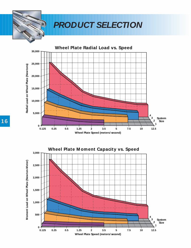
The graphs on pages 16 and 17 show thewheel plate radial, moment and thrust load
capacities versus speed for the four Lo Prosystem sizes. The bearing load ratings are basedon 2,500 hour average life (L50) data. The loaddata is very conservative and is based on theAFBMA Standard and American NationalStandard entitled “Load Ratings and FatigueLife for Ball Bearings” approved July 17, 1990.Actual industry data for our bearings, as shownin the system drawing sections, substantiatesthe conservative nature of this data. It isimportant to note that our systems are availablewith multiple wheel plates per track. Thisallows maximum flexibility in selecting the bestsystem design for your application.
OO TT
SS
OO
TT
1414

V E R S A T I L E I N D E S I G N
TM
BISHOP-WISECARVER CORPORATIONT H E F U T U R E O F L I N E A R M O T I O N
OUR 50TH YEAR
1515
SAMPLE LOAD EXAMPLE LOAD EXAMPLE LOAD EXAMPLE LOAD EXAMPLE LOAD EXAMPLE LOAD EXAMPLECALCULATIONS #1 #2 #3 #4 #5 #6
whereL = load (N)H = distance (m)D = distance (m)a = acceleration
(9.8 m/sec2)
Primary View ➔
Secondary View ➔
Carriage Insignificant Insignificant Insignificant Insignificant = L + LRadial Load compared to compared to = L compared to compared to (a D/9.8 X)(N) Moment & Moment Load Moment Load Moment Load where X = for
Thrust Loads Sys#1 = 1; Sys#2 = 1.5Sys#3 = 2; Sys#4 = 3
Carriage Insignificant Insignificant Insignificant Insignificant InsignificantThrust Load = L compared to compared to compared to compared to compared to(N) Moment Load Moment & Moment Load Moment Load Radial Load
Radial Loads
Carriage L (H + .019) a = L D + = L (D + .019) + = L (D + .019) + = L D + InsignificantMoment Load 9.8 L (D2 + H2)1/2 L (D + .019) L (D + .019) L (H + .019) a compared to(Nm) (a/9.8) (a/9.8) (a/9.8) 9.8 Radial Load
Data can be automatically calculated by using the Smart Selector Program which can be found on ourAll Products CD and on the custom software page of our website www.bwc.com/TechInfo/Software.asp.
loads on the appropriate graphs and make thesystem selection based on the highest systemsize determined. The graphs show wheel platecapacity based on the number of wheelshandling the load.
Once the loads and speed are determined,enter the values into the appropriate
graphs below. The location of the speed versusload point will determine the minimum systemsize required to handle your application. Ifmore than one load is present, graph all the
OO
1616
PRODUCT SELECTION
Wheel Plate Radial Load vs. Speed30,000
25,000
20,000
15,000
10,000
5,000
00.125 0.25 0.5 1.25 2 3.5 5 7.5 10 12.5
12
34
Wheel Plate Speed (meters/second)
SystemSize
Rad
ial L
oad
on
Wh
eel P
late
(N
ewto
ns)
Wheel Plate Moment Capacity vs. Speed3,000
2,500
2,000
1,500
1,000
500
00.125 0.25 0.5 1.25 2 3.5 5 7.5 10 12.5
12
34
Wheel Plate Speed (meters/second)
SystemSize
Mo
men
t Lo
ad o
n W
hee
l Pla
te (
New
ton
-Met
er)

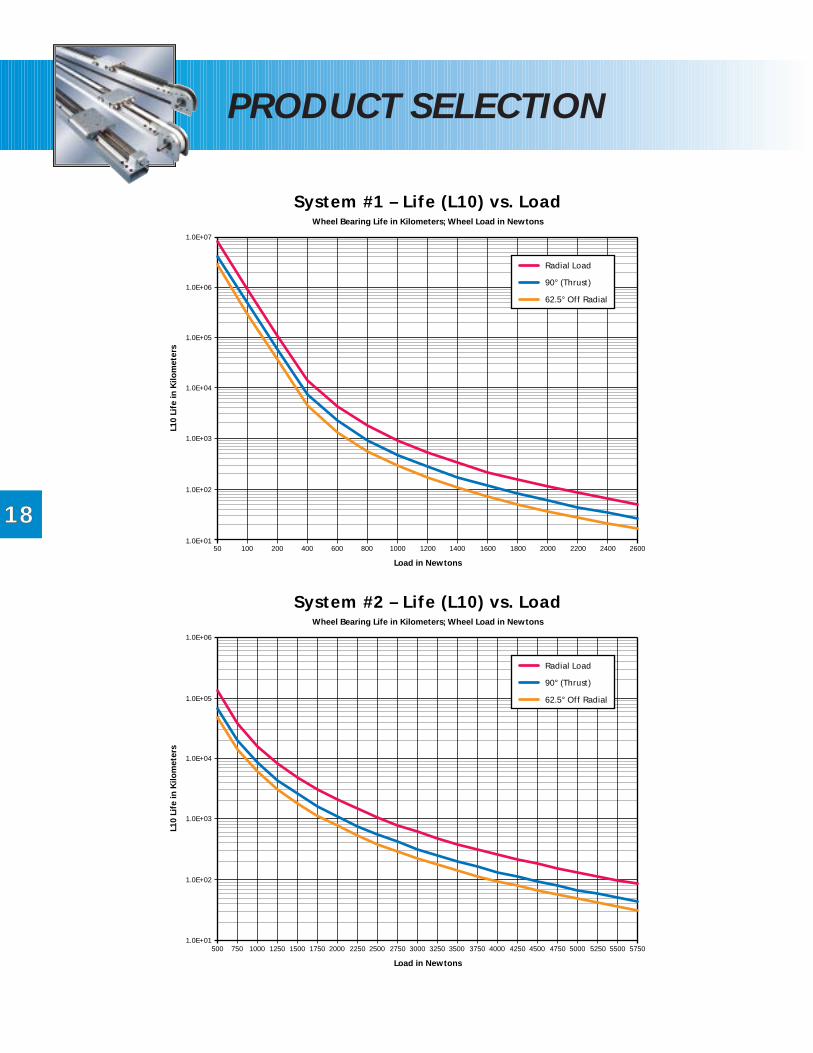
Abearing rated (L10) Life vs. Load curve foreach system size is shown on pages 18 and
19. The graphs are based on the load versus lifeof one wheel bearing. To determine the life ofa wheel plate, the wheel plate load needs tobe divided by the number of wheels supportingthe load. Typically for radial loads there aretwo wheels supporting the load, and formoment and thrust loads there are four wheelssupporting the load. For comparison purposes,it is important to note that the rated life (L10) isapproximately one-fifth of the average life (L50)which is where 50 percent of the group ofbearings will complete or exceed.
The life of the bearings is a cube function ofthe design load to actual load at any given
speed. Therefore, if you increase the loadcapacity of the system by 2, you extend the lifeby 23 or 8 times. For example, if a size #1 systemhandled a radial load of 800 N (400 N perwheel) it would have a rated life of 600x102 kmof travel. Lets assume with the duty cyclerequirements that the rated life equates to oneyear. A #2 system would have a rated life ofapproximately 10,600x102 km of travel. Withthe same duty cycle the #2 system would lastover seventeen years. Therefore, by increasingthe system size, significantly increases the ratedlife of the system.
TT AA
1717
V E R S A T I L E I N D E S I G N
TM
BISHOP-WISECARVER CORPORATIONT H E F U T U R E O F L I N E A R M O T I O N
OUR 50TH YEAR
Wheel Plate Thrust Capacity vs. Speed40,000
35,000
30,000
25,000
20,000
15,000
10,000
5,000
00.125 0.25 0.5 1.25 2 3.5 5 7.5 10 12.5
12
34
Wheel Plate Speed (meters/second)
SystemSize
Thru
st L
oad
on
Wh
eel P
late
(N
ewto
ns)
1818
PRODUCT SELECTION
1.0E+07
1.0E+06
1.0E+05
1.0E+04
1.0E+03
1.0E+02
1.0E+0150 100 200 400 600 800 1000 1200 1400 1600 20001800 2200 2400 2600
System #1 – Life (L10) vs. LoadWheel Bearing Life in Kilometers; Wheel Load in Newtons
Load in Newtons
L10
Life
in K
ilom
eter
s
Radial Load
90° (Thrust)
62.5° Off Radial
1.0E+06
1.0E+05
1.0E+04
1.0E+03
1.0E+02
1.0E+01500 750 1000 1250 1500 1750 2000 2250 2500 2750 3000 3250 3500 3750 4000 4250 4500 5250 55004750 5000 5750
System #2 – Life (L10) vs. LoadWheel Bearing Life in Kilometers; Wheel Load in Newtons
Load in Newtons
L10
Life
in K
ilom
eter
s
Radial Load
90° (Thrust)
62.5° Off Radial

V E R S A T I L E I N D E S I G N
TM
1919
1.0E+06
1.0E+05
1.0E+04
1.0E+03
1.0E+02
1.0E+01500 1000 1500 2000 2500 3000 3500 4000 4500 55005000 6000 6500 7000 7500 8000
System #3 – Life (L10) vs. LoadWheel Bearing Life in Kilometers; Wheel Load in Newtons
Load in Newtons
L10
Life
in K
ilom
eter
s
Radial Load
90° (Thrust)
62.5° Off Radial
1.0E+07
1.0E+06
1.0E+05
1.0E+04
1.0E+03
1.0E+02
1.0E+01500 1000 2000 3000 4000 5000 6000 7000 90008000 10000 11000 12000 13000 14000
System #4 – Life (L10) vs. LoadWheel Bearing Life in Kilometers; Wheel Load in Newtons
Load in Newtons
L10
Life
in K
ilom
eter
s
Radial Load
90° (Thrust)
62.5° Off Radial

PRODUCT SELECTION
2020
The correct system size has now beendetermined. The next step is to determine
what type of wheel plate is best for yourapplication. The circumference of the wheel isgreater at the major diameter than the minordiameter resulting in a constant wiping actionon the track which creates a self-cleaning affect.In many applications, lubrication between thewheel and track will greatly increase track life.In clean, lubricated applications using wheelplate wipers, the track and wheel surface canbe expected to approach the bearing life.As hardness of the contaminants approachesthat of the track and wheels, the wear ratewill increase. A value for this can only bedetermined by experiment. Therefore, havinglubricated wipers will significantly increasethe life of the system, especially for thoseapplications with high duty cycle and/or highacceleration or deceleration. The environmentand the application needs to be carefullyconsidered when selecting design features suchas wipers. Oscillating motion resulting in lessthan a full rotation of the wheel under loadcan cause accelerated wear of the bearing ballsand raceways. The system life is based on thewheel rotating at least one revolution for thesystem stroke. Your local Bishop-WisecarverCorporation representative or the factory canhelp you in choosing the best system for yourapplication. Call us today to discuss your linearmotion needs at (888) 580-8272.
Drive Product Selection
The criteria which determines the best driveoption for your application includes length
of travel, speed, acceleration and decelerationforces, positioning repeatability, environment,and external system forces. Refer to theappropriate drive product section (pages 4through 11) for the drive products available andthe corresponding load capacities. Your localBishop-Wisecarver Corporation representativeor the factory can help you in choosing the bestLo Pro system for your application.
Engineering Aids
Visit our website at www.bwc.com to viewthe latest information on all our products.
From our website you can download ourproprietary software and CAD files that will aidyou in designing a Lo Pro system into yourcurrent application. The Lo Pro Selectorsoftware provides the first step in selecting themost appropriate Lo Pro system for yourapplication. The program efficiently calculatesbearing loads, design layouts, and evaluationof system options in an easy-to-use interface.Lo Pro SmarTrak is a seamless AutoCAD orIntelliCAD plug-in that creates custom Lo Prosystem drawings, with the options that yourequire, drawn to manufacturers’ specificationsin just minutes. Your local Bishop-WisecarverCorporation representative or the factory canhelp you in choosing the best Lo Pro system foryour application.
TT
V E R S A T I L E I N D E S I G N
TM
TT
VV

BBB
BISHOP-WISECARVER CORPORATION
ISHOP-WISECARVER CORPORATIONis a California Company incorporatedin 1950 and headquartered inPittsburg, California. Bishop-
Wisecarver is an innovative company with manypatents including the Dual-Vee wheel bearingand track components. We have been sellinglinear motion products for more than twentyyears. Our Lo Pro product line was introducedin response to an industry need to have aconvenient, precision engineered, cost effective,easy to install and maintain linear motionsystem that could perform in contaminatedenvironments. The Lo Pro systems integrateour Dual-Vee components into linear motionsystems.
At Bishop-Wisecarver, we understand thedemands of the linear motion industry.
Our network of factory trained representativesare available to support your linear motionneeds. Engineers at the factory are readyand prepared to offer assistance in productselection and installation. Our manufacturingfacility is designed to quickly assemble and ship
your order. Much of our success comes fromproviding quality products and service. Ourgoal is to be your single source for linearmotion components and systems.
Our product line is ever increasing to meetyour latest demands. As we celebrate
our 50th anniversary, Bishop-Wisecarver willcontinue to research and develop new productsdesigned to meet your current and futureneeds. Meeting the demands of thisincreasingly complex industry is a challenge wegladly accept.
Visit our website at www.bwc.com for thelatest information on all our products.
Bishop-Wisecarver Corporation has created auser-friendly website that provides you withcomprehensive product information, softwaretools, CAD files, application stories, and yournearest sales representative. Our All Products CDprovides complete product information in aCD-ROM format. Call us today at (888) 580-8272to discuss our solution to your linear motionneeds.
AA
OO
VV

LP-M 9/99 10K
2104 Martin Way, Pittsburg, CA 94565-5027(925) 439-8272 • Fax (925) 439-5931
Toll Free (888) 580-8272
For current product information –www.bwc.com
CMCommercial Slide System
All ProductsLinear Motion CD
Gen IIPrecision Slide System
Lo ProLinear Motion System
RTSRing Slides & Track System
HDSHeavy Duty Slide System
Lo ProWith Steel Support Beam
Powerslide-2Guided Rodless Cylinder
SL2 Stainless Steel BasedSlide System
DLS Linear Transmission& Positioning System
DTSDriven Track System
Dual-VeeSingle Edge Slide System
LIMITED WARRANTYBishop-Wisecarver Corporation warrants, to the original purchaser only, that the products (a) conform to the specifications published in this
catalogue or as otherwise communicated to the purchaser, and (b) are free from defects in material or workmanship. This warranty expires one year from the date of delivery. Any failure of the products to conform to the foregoing warranty must be communicated to Bishop-Wisecarver Corporation in writing within 13 months after delivery. Bishop-Wisecarver Corporation shall have the option, in its discretion, of correcting any failure or defect, providing replacement products, or providing a full refund of the purchase price. These remedies are the purchaser’s exclusive remedies for breach of warranty. Any repair of defective products, including parts and labor, will be performed at Bishop-Wisecarver’s expense and at its facilities. All freight must be prepaid by the customer.
The limited warranty and limited remedy set forth above constitute the only warranty of Bishop-Wisecarver Corporation and the purchasers only remedies in the event such warranty is breached. The foregoing limited warranty is exclusive of all other warranties pertaining to the products, written or oral, express or implied, including but not limited to the implied warranties of merchantability and fitness for a particular purpose, or against patent infringement.
Bishop-Wisecarver Corporation does not warrant (a) defects caused by failure to provide a suitable installation environment for the product, (b) damage caused by use of the product for purposes other than those for which it was designed, (c) damage caused by unauthorized attachments or modifications, (d) products which have been repaired or altered outside of our facility, or (e) any other abuse or misuse by the purchaser.
In no event will Bishop-Wisecarver be liable for any special, incidental or consequential damages, including but not limited to claims for injury to or death of persons, or for damage to property, based on breach of warranty, breach of contract, negligence, strict tort or any other legal theory, including loss of profits or revenues, loss of use of the product, cost of any substitute equipment or facilities, and the claims of customers or other third parties. Any action for breach of warranty must be commenced within 15 months following delivery of the product.
The purchaser acknowledges that it is selecting the product and/or system choices for its particular application, and is relying on its own expertise and not the expertise of Bishop-Wisecarver Corporation in making such selections.
OurProducts
Product Catalogs
CAD Files
Why Choose Us?
Contact Us
CustomSoftware
BISHOP-WISECARVER CORPORATIONT H E F U T U R E O F L I N E A R M O T I O N . E S T. 1 9 5 0
2104 Martin WayPittsburg, CA 94565(925) 439-8272www.bwc.com
© Copyright 1999Bishop-Wisecarver Corp.
RELEASE 1.0
BISHOP-WISECARVER CORPORATIONT H E F U T U R E O F L I N E A R M O T I O N . E S T. 1 9 5 0
OUR 50TH YEAR