long term maintenance issues for bridges/media/busind/techstdpubs/technical notes... · tn146 long...
TRANSCRIPT

Technical Note 146 Long Term Maintenance Issues for Bridges January 2016

Technical Note, Transport and Main Roads, January 2016
Copyright
http://creativecommons.org/licenses/by/3.0/au/
© State of Queensland (Department of Transport and Main Roads) 2016
Feedback: Please send your feedback regarding this document to: [email protected]

TN146 Long Term Maintenance Issues for Bridges
Technical Note, Transport and Main Roads, January 2016 1
1 Introduction
Bridges have a 100 year design life. As a responsible asset owner, the Department of Transport and Main Roads (TMR) are vested by the public to ensure value for money and minimum whole of life for a bridge and other high risk infrastructure. It is essential that infrastructure be robust and durable.
The department has identified high risk infrastructure that requires 100 year design life as well as other infrastructure that only requires a shorter 40 year design life.
On high volume roads, the traffic volumes mean only short windows are permitted for maintenance that involves reduction in the number of traffic lanes or road closures.
As an infrastructure owner, the department manages infrastructure from concept through design, construction, maintenance, operation and demolition.
2 “Innovations” Transport and Main Roads does not accept
Table 2 – “Innovations” the department does not accept
‘Innovative’ Practices/Products Rationale
3.2 Unlined cast-in-place piles for bridges Durability issues – most applications (conditions apply)
4.1 Reinforced concrete driven piles for bridges
Serious durability issues due to tension stressing driving, and long term durability issues
5.1 Hollow spun piles for bridges Cracking and rehabilitation issues
6.1 Continuous Flight Auger (CFA) piles and screw piles
CFA piles: Durability issues Screw piles: limited axial capacity and durability issues
7.3 Design and WHS considerations Design must consider access for inspection and maintenance
8.1 Bearing restraint To ensure bearing does not ‘walk’
9.1 & 9.2
Steel column footings below ground Corrosion issues with casting column and base plate
10.1 Bracing “held in place” by silicone bolts Fraudulent use of silicon
10.3 & 10.4
Butt welded off cuts to fabricate columns and connections
Issues with fabricators using off cuts and butt welds to prevent crevice corrosion
11 Why TMR does not accept ‘hot air curing’ of concrete
Policy supports the use/non-use of these products, where appropriate
12 Fabrication of posts for bridge traffic Conforming compound welders ensure safety for the road user
13 Holding down bolts – Grade 8.8 Bolts The introduction of inferior processes do not comply with AS / NZS 1252 – strength and resilience is compromised
14 Non-conforming Pile Driving Hammer Exceeding allowable tension stresses in the prestressed concrete pile during

TN146 Long Term Maintenance Issues for Bridges
Technical Note, Transport and Main Roads, January 2016 2
‘Innovative’ Practices/Products Rationale
15 T-roffs Deviating from proven standard designs may result in unexpected defects (not all risks being addressed when changing design, that is, temperature)
16 Use of propriety products – Danley key joints
Compromise durability
3 Unlined piles for bridges
3.1 Why Transport and Main Roads requires lined piles (MRTS63)
It is accepted that the use of unlined piles could involve a construction cost reduction. However, the department’s policy is to use steel lined piles as required by MRTS63 Cast-In-Place Piles and MRTS63A Piles for Ancillary Structures.
The reasons the department mandates the use of lined piles are all related to durability of the piles. Transport and Main Roads have had a number of issues with the use of unlined piles in the past, most critically over that section of the pile which is subject to water inundation (or fluctuation water level within typically alluvial profiles).
A steel liner will effectively provide a pile which has an additional layer of protection within the critical zone when compared with an unlined pile. Even in an extreme environment (marine tidal or splash zone) the steel liner will provide an extra life of at least 50 years, while in less aggressive environments this period is much longer. The department has undertaken testing of pile concrete in varying environments and have found that even when the pile concrete is well constructed, the durability of the pile concrete may not achieve a 100 design year life. However, when the extra protection provided by the steel liner is included this life is easily achieved. Liners also ensure a positive connection between the top of the pile, and the abutment/headstock/pilecap is obtained.
A secondary consideration is the use of a permanently lined pile which also eliminates the possibility of the pile caving in the lined section. Furthermore, when a liner is removed there is a likelihood of the wet concrete being damaged during the removal process and this is totally eliminated by mandating permanent liners.
In essence the mandating of liners results in a more durable product with significantly less construction risk, than would occur with unlined piles.
The following pictures highlight some of the issues with the use of unlined piles.

TN146 Long Term Maintenance Issues for Bridges
Technical Note, Transport and Main Roads, January 2016 3
3.2 Pictures for unlined insitu piles
Figure 3.2-1: During top down construction. Unlined pile into dry, highly adsorbent, low strength, deeply weathered, sedimentary rock. Moisture sucked out of the concrete. Surface concrete deteriorated to the level of the reinforcement
Figure 3.2-2: Unlined pile (designed as such), scour of surface concrete down to the reinforcement following a significant flood event (the bridge was still under construction at the time)
Figure 3.2-3: Unlined piles note the poor connection between the pile and the abutment, particularly on the 3rd and 4th pile

TN146 Long Term Maintenance Issues for Bridges
Technical Note, Transport and Main Roads, January 2016 4
4 Driven Reinforced Concrete (RC) piles for bridges
4.1 Why Transport and Main Roads does not use reinforced concrete driven piles
Technical Note 124 Durability issues of reinforced concrete driven piles provides extensive information on this topic.
The use of driven, segmented, RC piles in lieu of the standard prestressed piles is often offered as a construction cost saving alternative. It is Structures section policy not to use driven RC piles on bridges.
The reasons for this policy is essentially related to the durability of piles. During piling, high stresses (particularly tension stresses) are induced into the piles which results in cracking of the piles. In the case of Pre Stressed Concrete (PSC) piles these stresses are resisted by both the reinforcement and the prestress, while in the case of RC piles, only the reinforcement is available to resist these forces. Furthermore the RC piles are designed to a design life of 40 to 60 years, while the Australian Bridge Code (AS 5100) requires bridges to be designed and constructed to at least 100 years.
Replacement of piles on bridges is an extremely expensive exercise. It is not unusual to find the replacement cost of only one or two piles exceeds the total original construction cost of the bridge. On this basis the use of less durable piles (that is, RC piles) is not in the long term interest of the department and should not be adopted as a cost saving “innovation”.
Further issues with the use of proprietary RC piles is that the piles are produced in standard lengths (typically 9 m and 6 m) to facilitate transport to the project site. This procedure necessitates multiple splices in the piles and splices used are not full moment splices thus not meeting the design requirements for bridges.
5 Pile types Transport and Main Roads does not accept
5.1 Hollow spun piles for bridges
5.1.1 Why the department does not accept hollow spun piles for bridges
Hollow spun piles are a proprietary design for driven concrete piles. Although this pile type was used, however not very widely during the 1970’s to 1980’s, issues identified the piles were not robust. During construction a number of the piles fractured during transportation. This was due to poor driving procedures and/or poor alignment of the hammer relative to the pile head. Furthermore, the majority of the remaining piles were found to be extensively cracked. Rehabilitating of hollow spun piles has become a continuing maintenance issue for some time, therefore hollow spun piles are no longer considered suitable for departmental structures as they are not considered to be a robust pile type.

TN146 Long Term Maintenance Issues for Bridges
Technical Note, Transport and Main Roads, January 2016 5
5.1.2 Issues with hollow spun piles
Figure 5.1.2-1: Cracked pile
Figure 5.1.2-2: Cracking at the head of a hollow spun pile
Figure 5.1.2-3: a, b and c: Three hollow spun piles on one project showing typical cracking

TN146 Long Term Maintenance Issues for Bridges
Technical Note, Transport and Main Roads, January 2016 6
Figure 5.1.2-4: Severe cracking of pile, concrete falling away from hollow piles showing loss of reinforcement
Figure 5.1.2-5: Section of a hollow pile
Figure 5.1.2-6: Fallen spall of concrete showing only rust exists where steel reinforcement should be
Figure 5.1.2-7: Cracking in piles with crack monitoring in place
5.2 Continuous Flight Auger (CFA) piles and screw piles
5.2.1 Discussion about CFA and screw piles for bridges
Bridge piles are subject to a combination of high axial load and high moment. There is a requirement for bridge piles to have a 100 year design life.

TN146 Long Term Maintenance Issues for Bridges
Technical Note, Transport and Main Roads, January 2016 7
Screw piles have limited axial capacity. Being made of steel they have minimal moment capacity and have less than a 100 year design life. Hence, these piles are not suitable for bridges.
The construction of continuous auger piles involves:
• unlined piles
• no control on material impregnating piles
• no control of moisture loss in the adjacent soil
• no control on reinforcement cage to ensure the position of the cage.
Additionally, both these pile types are outside the scope of AS 5100 Bridge Design. Consequently, both pile types are not permitted for bridges.
6 Provision for inspection and maintenance
6.1 Why provision for inspection and maintenance is required
The Workplace Health and Safety Act requires a designer to consider safety in all design work during the following phases:
• concept
• design
• supply/install
• construction/manufacture
• commission
• operation
• inspection
• maintenance and repair
• decommission/recycle/disposal.
The design shall consider the future requirements for safe access for inspection and maintenance, including areas adjacent to the bridge where workers can safely park and load/unload equipment. This will require the designers of the adjacent roadway to include safe pull-off areas for vehicles.
On major bridges, safe access for inspections necessitates, the design must include the provision of access gantries for future maintenance. On smaller bridges, the installation of support points to support future maintenance activities such as repairing, must be provided.
Other access requirements include:
• platforms at abutments to allow the safe inspection of bearings
• stairways to access locations and on batter slopes to access abutments
• fixed ladders, where appropriate, or temporary ladders with appropriate stabilising attachments
• hatchways to provide access and prevent unauthorised entry
• anchorage points for the inspection scaffold or safety harness.
TN146 Long Term Maintenance Issues for Bridges
Technical Note, Transport and Main Roads, January 2016 8
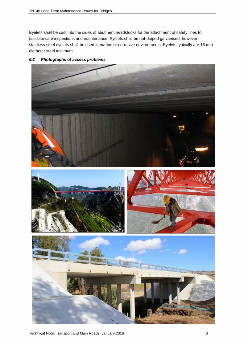
Eyelets shall be cast into the sides of abutment headstocks for the attachment of safety lines to facilitate safe inspections and maintenance. Eyelets shall be hot-dipped galvanised, however, stainless steel eyelets shall be used in marine or corrosive environments. Eyelets typically are 16 mm diameter steel minimum.
6.2 Photographs of access problems

TN146 Long Term Maintenance Issues for Bridges
Technical Note, Transport and Main Roads, January 2016 9
6.3 Bearing replacement
Elastomeric and pot bearings have a design life of 40 years whilst bridges have a design life of 100 years. Consequently it will be necessary to replace bearings.
In older existing bridges it was necessary to provide:
• worker access
• lifting point for bearings and equipment.
Both these options are expensive and time consuming. Additionally, these could have adverse impacts on traffic. The provision of bearing shelves for jacking and provision for access for worker areas by elevating the platform, improve efficiency and reduce costs.
The below photograph shows temporary access that has to be constructed at Currumbin Creek Bridge because provision was not made for access for bearing replacement.
Figure 6.3-1 – Falsework and access for jacking operation
During jacking, there has to be provision of a safety stool in case the jack or hose fails. This limits the amount the bridge can be moved if such a failure occurs.

TN146 Long Term Maintenance Issues for Bridges
Technical Note, Transport and Main Roads, January 2016 10
Figure 6.3-2 – Jack and safety stool to support bridge during maintenance work
7 Bearing pad recesses
7.1 Requirements for bearing restraint
Theoretically, if a bearing is positioned level and the load applied only vertically, the bearing will not move. In reality this never happens therefore the bearing needs to be restrained.
Consequently, it is necessary to restrain bearing to ensure the bearing does not “walk”. Refer to below photograph.
Restraint can be achieved by installing a bearing restraint or positive restraint.
Figure 7.1 – Restraint required to prevent ‘walking’
Jack
Space required for jacking
Restraint required to prevent ‘walking’

TN146 Long Term Maintenance Issues for Bridges
Technical Note, Transport and Main Roads, January 2016 11
8 Steel column footings above ground
8.1 Issues with steel columns footing below ground
Steel is susceptible to corrosion especially when it is buried in moist conditions. Poor detailing and/or poor construction practices can result in the steel post/column being buried. Moist conditions result in the development of ideal conditions for erosion.
Good construction and design should result in the base plate being positioned above ground. This is normally achieved by the use of a concrete pedestal in concrete plinth.
In areas with pedestrian traffic it may be necessary to raise the pedestal sufficiently high so it does not present a tripping hazard.
8.2 Corrosion issues associated with cast in base plates
Figure 8.2-1 – Corrosion of pole when buried in ground
Figure 8.2-2 – Corrosion of buried post

TN146 Long Term Maintenance Issues for Bridges
Technical Note, Transport and Main Roads, January 2016 12
Figure 8.2- 3 – Corrosion of post buried in concrete where water has seeped in
9 Unethical construction practises
Regrettably there are some unscrupulous people in the construction industry who take short cuts. Everybody should be on the lookout for such practises because the consequences may not be obvious and only become apparent in an extreme event.
9.1 Silicone bolts
On a bus station, bracing appeared to be held in place by bolts. Following a vehicle impact, it was found that due to a fabrication error, the installer had used silicone to hold the detail together. The bolt has been deleted and nuts were fraudulently installed to give the appearance of a bolt with nuts.
Supervisors need to vigilant to ensure this practise does not occur.

TN146 Long Term Maintenance Issues for Bridges
Technical Note, Transport and Main Roads, January 2016 13
9.2 Photographs of fraudulent bolts
Figure 9.2 – Fraudulent bolts
9.3 Why we don’t allow butt welded columns
The department’s design criteria specifies that butt welded short pieces of steel sections to fabricate a column are not permitted unless specially shown on the design drawings.
Experience has shown some disreputable fabricators create columns from off cuts where the:
• Wall size may vary and be less than specified. On the example shown, a thin section was used at the base which resulted in failure.
• Joint is made by welding the two pieces together then grinding flush. Consequently, the joint has inadequate structural capacity.
Silicone used to fill hole and glue nuts either side!

TN146 Long Term Maintenance Issues for Bridges
Technical Note, Transport and Main Roads, January 2016 14
Figure 9.3 – Fraudulent bolts
9.4 Butt welded connection to base plates
Butt welded connections are required to prevent crevice corrosion occurring at the joint.
• The galvanizing process consists of cleaning the steel in an acid bath prior to galvanizing.
• For a closed (e.g. circular column) fillet welded to a base plate. Acid is trapped in the gap and with time seeps causing corrosion.
• When butt weld are used there is no crevice for acid to be trapped in. It is a better long term detail.
Figure 9.4-1 - Post failure
Figure 9.4-2 - Posts fillet welded – not butt welded as required on drawings
6 mm thick
1.6 mm thick

TN146 Long Term Maintenance Issues for Bridges
Technical Note, Transport and Main Roads, January 2016 15
10 Use of set retarding admixtures in concrete
In the last few years some constructors have attempted to adopt a process whereby they excessively retard concrete mixes to “simplify” the placement process. This procedure is contrary to the requirements of MRTS70 Concrete and is not considered to be good construction practice.
A number of set retarding admixtures are on the market although only a limited number are on the list of departmental approved admixtures. Admixtures are selected based on chemical composition (sodium chloride – salt- for example is not permitted), for example. Generally, these admixtures fall into one of three classes.
10.1 Traditional set retarders
Traditional set retarding admixtures which retard the set for relatively short periods typically for less than one hour. This class of admixtures become a normal part of the concrete mix design requirement particularly when high cementitious contents are used. The admixture is incorporated into the mix and the initial set is retarded by a period dependant of the quantity of admixture used. The approved admixture list gives details of the approved admixtures and the maximum dosages which are acceptable for this type of admixture.
10.2 Hydration stabilizer
The second class are the group of admixtures which effectively “kill” the concrete until an “antidote” is included at which time the concrete is essentially a normal concrete again. This type of procedure can only be used while the concrete is still in the agitator as the antidote must be mixed into the concrete. It has also become common practice for some concrete suppliers to use the antidote admixture into concrete, which is starting to set prior to placement, as a method of retempering a mix which does not align to specification due to delays or other issues on site. The use of these admixtures is not generally approved except in situations where long haul distances are involved and a complete trial mix procedure has been undertaken to determine the required dosage of admixtures. This class of admixtures is not generally approved but may only be used in the “long haul situation”.
10.2.1 Long haul concrete
Technical Note 125 Long Distance Transport and Extended Placement Times for Concrete has been prepared for long haul concrete. This includes the required procedures for trial mix designs is available on the departmental web site.
10.3 Surface retarders
The third class are the surface retarders which are used to retard the surface of concrete to produce a specific surface condition, such as required for a construction joint. These retarders are not included in the mix but rather painted on the concrete surface or on the forms in those areas requiring a special treatment. There are several of these admixtures included in the list of approved admixtures.
The department has a procedure for approving admixtures for concrete. This procedure also looks at the maximum acceptable dosage for admixtures. It has been found on a number of occasions the dosages used to achieve the required (by the contractor) degree of retardation exceeds the maximum permitted dosage, thus potentially impairing the durability of the concrete.

TN146 Long Term Maintenance Issues for Bridges
Technical Note, Transport and Main Roads, January 2016 16
11 Why Transport and Main Roads does not accept “hot air curing” of concrete
11.1 Hot air curing
Hot air curing of concrete is a process when hot air is blown into the curing chamber associated with water misters and hessian placed on the concrete. The use of water mist associated with air curing is a problematic process as it has been found misting nozzles tend to block resulting and an uneven water and heat distribution.
It has been found control of an air curing system is extremely problematic as it is extremely difficult to achieve uniform curing conditions (temperature and humidity) throughout the length of the bed. Fundamentally, for curing to be effective it must ensure uniform conditions across the full exposed surface of the element. “Air curing” does not achieve this requirement and therefore is not approved.
11.2 Approved curing
Approved methods of curing are steam curing, hot water curing and moist curing. Further details are in MRTS70 Concrete.
12 Fabrication of posts for bridge traffic
Bridge traffic rail is provided at the edge of the bridge to prevent errant vehicles from leaving the carriageway and falling off the bridge. This could be fatal for the occupant if the vehicle falls into deep water. Similarly, the bridge traffic barrier is to protect occupants in road or train lines below the bridge from being impacted from vehicles that fall off the bridge.
The weld at the base of a bridge traffic barrier is a compound weld consisting of a full penetration butt weld and a fillet weld. These welds have been tested to ensure they conform to the design criteria of AS 5100 Bridge Code. On some occasions, an unscrupulous welder may only provide a fillet weld. This has an inferior strength and poses a serious risk to road users.
The attached photos show the damage caused when a small Franner crane impacted the substandard bridge traffic barrier.
Figure 12-1 – Failure of bridge traffic barrier when impacted by small crane

TN146 Long Term Maintenance Issues for Bridges
Technical Note, Transport and Main Roads, January 2016 17
Figure 12-2 – Fillet weld connection instead of butt welded connection
Figure 12-3 – Lack of strength of defective weld

TN146 Long Term Maintenance Issues for Bridges
Technical Note, Transport and Main Roads, January 2016 18
13 Holding down bolts – Grade 8.8 Bolts
Hold down bolts have a very important role in absorbing impact and thereby provide a mechanism to prevent vehicle access beyond that point. For hold down bolts to effectively work their manufacture must comply with AS/NZS 1252 and MRTS78 Fabrication of Structural Steelwork. This ensures they are structurally sound and their strength is not compromised.
It is being found that incorrect manufacturing practices are being undertaken. In some cases nuts are being installed on the end of blank rods which have a thread cut on one end. The nut is not only welded onto the end of the blank rod, so the assembly appears to be a bolt assembly. This type of application was a common practice with all construction up to 2005.
The welding of nuts onto the end of round bars results in an inferior strength fastener.
TMR has written a Technical Note 66 Commercial and Fabricated Bolts and Nuts (available on TMR website) explaining the correct process to be followed if a commercial bolt is not able to be purchased.
Figure 13-1 – Fabricated bolt instead of forged bolt
Figure 13-2 – No connection between shaft of bolt and nut in welded bolt

TN146 Long Term Maintenance Issues for Bridges
Technical Note, Transport and Main Roads, January 2016 19
Figure 13-3 – View of head of fabricated bolt
Figure 13-4 – Failed bolt due to fabricated bolt being used instead of forged bolt
13.1 Anchorage
To achieve the maximum impact results in the hold down bolt mechanism the accepted tensile capacity for the bolting system requires a reading of approximately 200 kN for each M24 bolt.
14 Non-conforming pile driving hammer
14.1 Driving with a light hammer (non-conforming)
MRTS65 Precast Prestressed Concrete Piles has a clause specifying conforming pile driving hammers. The weight of these hammers is such that the pile can be driven into the ground, the top of the pile is not damaged and there is not a tension wave in the pile that will exceed the axial compression in the pile.
Contractors often propose a hammer that is in accordance with MRTS65 too light in relation to the weight of the pile. This results in higher tension waves in the pile during driving and an increased risk on pile damage.
MRTS has a concession for an alternative light hammer that can be used There are extra restriction including the use of a Pile Driving Monitor on the piles to ensure that the magnitude of the tension wave is monitored and controlled.

TN146 Long Term Maintenance Issues for Bridges
Technical Note, Transport and Main Roads, January 2016 20
Details of pile sleeve on 16T hammer (note inserts used to keep the pile in a close fit with the sleeve). This leads to a perpendicular motion of the anvil on the pile head which will cause least damage to the pile.
Figure 14.1-1 – Spacer in pile sleeve to stop hammer moving
Figure 14.1-2 – Pile driving
15 T-roffs
15.1 Design changes in T-roffs
Modifications in the standard t-roff design (for example, thicker diaphragms, less reo) should not be automatically allowed (even with RPEQ approval from designer) without having a good understanding of the risk this may have on the manufacturing process. T-roffs have relatively thin walls and diaphragms and are sensitive to stresses caused by hydration heat during the curing process.

TN146 Long Term Maintenance Issues for Bridges
Technical Note, Transport and Main Roads, January 2016 21
The Material Unit of Bridge Construction Maintenance and Asset Management can provide advice on appropriate adjustments to design to minimize heat induced stresses.
Figure 15 – Poor quality concrete due to heat of hydration
16 Use of propriety products – Danley key joints
Culvert base slabs/aprons have key joints as detailed in the TMR standard drawings. Contractors often propose to use propriety products as sacrificial form work for a Key Joint. The advantages for the contractor are:
• easy installation and NO timber block outs
• no removal of formwork
• adjacent sections of the base slab can be poured in one go resulting in major time, transport savings.
Danley product is a thin galvanised sheet metal product and when incorporated in the based slab, will corrode easily in a wet environment (as this is usually the case with culvert base slabs/aprons). Danley key joints are suitable for indoor construction not exposed to the element and have insufficient durability for culverts and other external applications.
Figure 16 – Key joint detail
