long lam, cpe michael vose, cpe sean koceski, cpe … 24 cdr_fin… · design the filter and...
TRANSCRIPT

Mode-S Receiver and ADS-B Decoder
Group 24
Sean Koceski, CpELong Lam, CpEMichael Vose, CpE
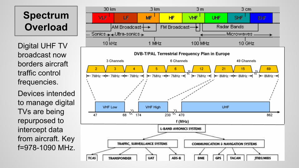
SpectrumOverload
Digital UHF TV broadcast now borders aircraft traffic control frequencies.Devices intended to manage digital TVs are being repurposed to intercept data from aircraft. Key f=978-1090 MHz.

Loss of Control
As traditional radar is replaced with GPS-based aircraft tracking (ADS-B), all you need is an air-traffic receiver (Mode-S) to monitor the local airspace like a ground station. Private worldwide networks of these receivers now exist.

MotivatorsSeveral national and international agencies have called for the hardening of our critical air-traffic control infrastructure. Some have proposed changes, but they don’t always agree on what should be done.
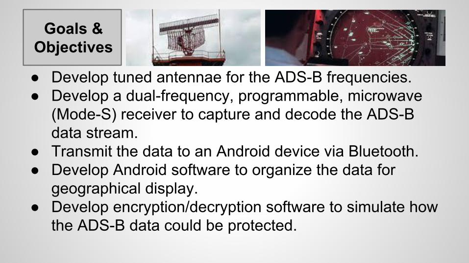
Goals & Objectives
● Develop tuned antennae for the ADS-B frequencies.● Develop a dual-frequency, programmable, microwave
(Mode-S) receiver to capture and decode the ADS-B data stream.
● Transmit the data to an Android device via Bluetooth.● Develop Android software to organize the data for
geographical display.● Develop encryption/decryption software to simulate how
the ADS-B data could be protected.

Specifications
Category Description Target(s) Achieved
Antennae Two frequency-tuned, coaxial, collinear masts housed in rigid plastic tubing.
f=978 MHz, f=1090 MHz. 1090 MHz
ReceiverDual frequency (non-tunable) microwave receiver with a large capacity for custom signal processing.
>= -25dB signal reception for an estimated range of 100 km.
Yet to be Tested
Power Battery powered. >= 1-hour active operation. At least 1-hour achieved, actual length unknown
Response Continuously decoded/decrypted position and altitude information with minimal delay.
<= 5-second delay from reception to display.
Yet to be Tested
Weight Entire system to be carried by one person. <= 25 lbs. (Luggable). Total weight of all subsystems <15 lbs.
CostLow cost, (though the initial prototype may be of higher cost.)
<= $500.00 $892.12

Overall Block Diagram

Design Approach
Tune the antennae and build a receiver using RF Detectors, ADCs, and FPGAs (rather than an SDR approach) to increase sensitivity and introduce customizable signal processing logic.
A
A ManchesterSignal Decoding
Merge Signals
Possible Crypto Implementation
UART Logic
Bluetoothv2 Module

AntennaeAntennae will be stacked vertically to limit interference. In Coaxial Collinear (CoCo) Design, the lengths of the segments are specific to the frequency of the signal to be received.
Alternating the current distribution between the core and the shield in half-wavelength sections drives it to become cophasal. This yields the radiating current and a relatively large gain.

AntennaeCoaxial Cable used is RG-213/U 50 Ohm. The choice for 50 Ohm cable was to match impedance with the expected impedance of the RF detector chips. Copper shielded cable was needed to allows for soldering the braid to the copper center conductor.
Exposed copper conductor is needed to allow for a clean radiation pattern
Copper tubing and ferrite beads are needed to cancel out signals traveling on the ground plane of the feeder line.

Antennae Frequency ch A dB ch B dB
900 0.5 -10
910 -0.4 -10.5
920 -0.1 -10.1
930 0.8 -11.1
940 0.3 -14.8
950 0.4 -16.5
960 1.2 -16.5
970 1.6 -14.4
980 1.3 -14
990 1.6 -12.7
A) B) C)
Frequency ch A dB ch B dB
908 -0.2 -20
918 0.5 -15
928 0.3 -12.7
938 0.2 -12.4
948 0.7 -10.8
958 1.1 -10.3
968 1.1 -9
978 1.8 -8
988 1.5 -8.8
Frequency ch A dB ch B dB
900 0 -11.2
910 -0.6 -11.1
920 0.2 -10
930 1.3 -10.4
940 0.9 -13.2
950 1 -18.5
960 1.6 -21.2
970 2.2 -14.6
980 1.9 -13.1
990 2 -12
A. Intentional ground reflection 1090 Antenna
B. 978 Antenna (798 showing peak result)
C. 1090 Antenna (results leading toward peak)
RL = 20log((VSWR + 1) / (VSWR-1))

FiltersThe high frequency of the desired signals prevents the use of discrete components. A transmission line model is used to design the filter and hairpin microstrips are used to build it.
This is one of three pages of the schematic for 978 MHz. The input port is shown on the left.
The other pages are omitted for brevity.

FiltersChallenge
The completed, narrow BPF is of the 5th-order and adheres to a symmetric design. The actual size of the filter is roughly 3.75x1.80 in. The 1090 MHz filter is slightly smaller.
Finding useful software to model the filters and generate the layout was a challenge and resulted in an additional sponsor:
Keysight(Agilent)
Filters
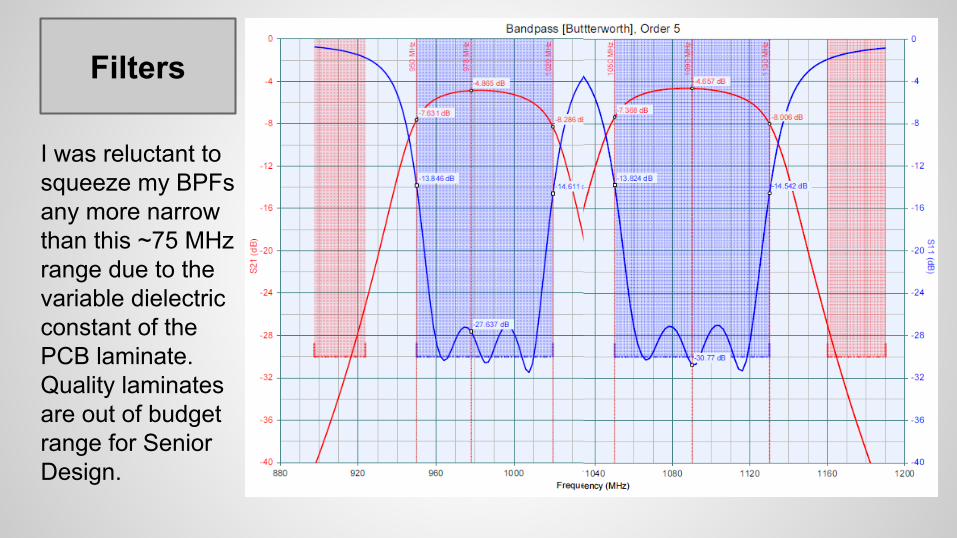
I was reluctant to squeeze my BPFs any more narrow than this ~75 MHz range due to the variable dielectric constant of the PCB laminate. Quality laminates are out of budget range for Senior Design.

Filters
Connected to both ends of the filter are gold plated SMA connectors to connect the incoming signal from the antenna to the filter and the filtered signal to the RF detector.
Filters
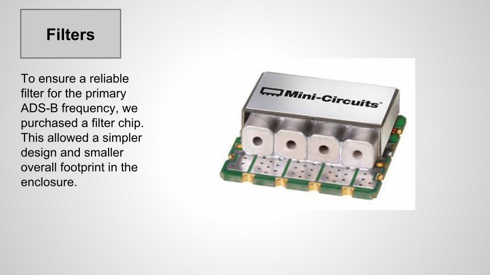
To ensure a reliable filter for the primary ADS-B frequency, we purchased a filter chip. This allowed a simpler design and smaller overall footprint in the enclosure.
RF Detector
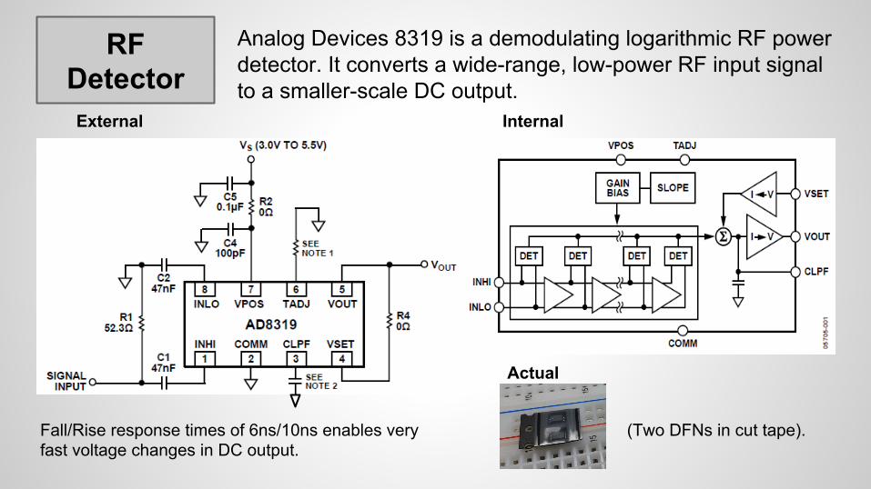
Analog Devices 8319 is a demodulating logarithmic RF power detector. It converts a wide-range, low-power RF input signal to a smaller-scale DC output.
InternalExternal
Actual
Fall/Rise response times of 6ns/10ns enables very fast voltage changes in DC output.
(Two DFNs in cut tape).

ADCMaxim Integrated 1192 is a high speed analog-to-digital converter. At this point, our input signal is single-ended DC in the 0.5v to 1.5V range. After this step, it’s 8 digital logic lines.
Internal-2Internal-1
Actual
(Two QFNs in a tube).
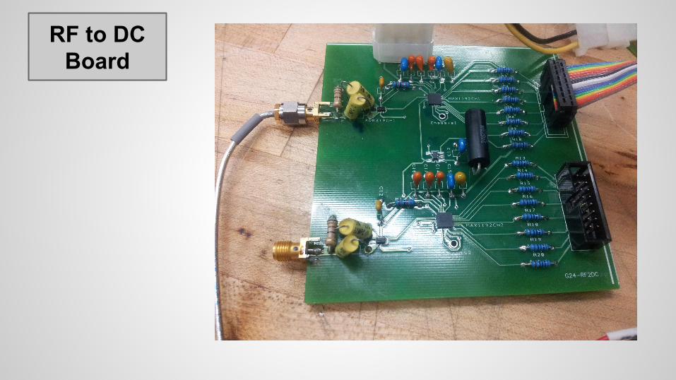
RF to DC Board
Internal-2
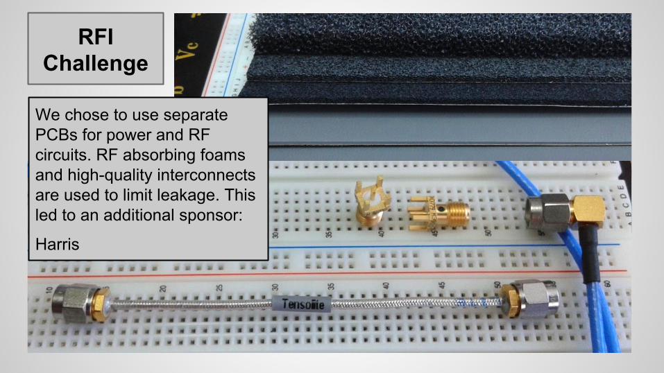
RFI Challenge
We chose to use separate PCBs for power and RF circuits. RF absorbing foams and high-quality interconnects are used to limit leakage. This led to an additional sponsor:
Harris

Manchester Decode
The ADS-B data stream must first be decoded before its content can be evaluated. One small FPGA follows each ADC to address this need.
The dual-inline packaging format of this FPGA breakout board simplifies testing and the physical programming of the device.
A JTAG interface header is used for programming. Xilinx XC2C64 in a 2.16 x 0.7 in. DIP package

Signal Merge
Before the two decoded data streams can be sent to the Android device for final processing, they must be sequenced, merged, and then buffered for a standard UART interface.
As time permits, some crypto- graphic functions may be located here for testing.
This package uses a USB programming interface.
Xilinx XC6SLX4-2CPG196 in a 2.6 x 0.7 in. DIP package

BluetoothModule
Digilent PmodBT2 receives the processed data stream and transmits the data to a connected Android device.

The circuits below will be used to connect the receiver to the power supply.
Power Circuit Diagram
Circuit A -- 12V to 5V
Circuit B -- 5V to 3V3

Power Supply

Stacked PCBs
1. Power Board2. 1090 MHz Filter (RF1)3. 978 MHz Filter (RF2)4. RF1 and RF2 to Digital5. Digital Logic to UART❏ Bluetooth Module
Allows independent ground planes and space for RF foam or shielding. Requires high-quality interconnects.

Stacked PCBs

MobileApplication
Features
Selection of tracking a specific aircraftAutomatic adjustment to current locationManual control over viewable airspaceDisplay all aircrafts within range of antenna
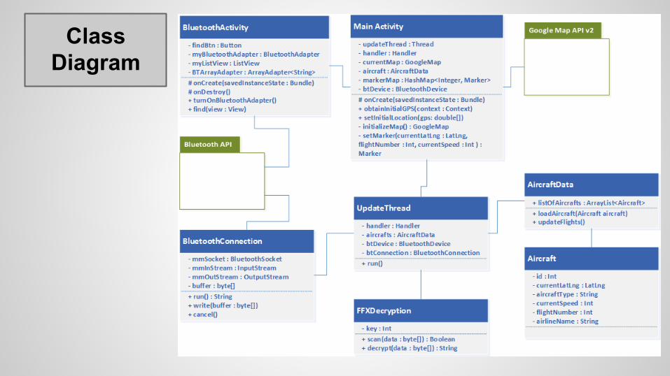
Class Diagram

ApplicationOverview

ADS-BFormat ADS-B message format is referred to as extended squitter.
Message Type Surveillance-Control Extended Data* ICAO Code +
5-bits 27-bits 56-bits(Format depends on message type). 24-bits
Capability 3-bits
Largest Possible Encryption Target104-bits
● Airborne Position Squitter● Surface Position Squitter● Airborne Velocity Squitter● Aircraft Identification Squitter
● DO-260A State and Status
★ The ‘squitters’ we need occupy the extended data field one by one.

ADS-B Data StreamEncryption/Decryption
ADS-B broadcast strictly prohibited.A test program will run on Android to capture the data stream and encrypt it as test data.Encryption will be a modified version of the FFX algorithm. FFX is a format-preserving encryption (FPE) scheme.The encrypted test data will be input to the Android aircraft-tracking display software.
FFX encrypts encrypted data to compensate for the inherent weakness of matching input and output data size.
The underlying encryption will start simple (XOR), and as time permits further testing, it will increase in complexity.

Summary of Major Design Decisions● Antenna design choice
○ Two tuned antennae (CoCo) vs alternatives.● Software Defined Radio vs an explicit ADC/FPGA
○ ADC/FPGA was selected to implement a fully programmable system.
● PCB organization/interconnects○ Separate PCBs to better manage RFI.
● Interface options○ Bluetooth transmission to Android.
● Encryption options○ Format-Preserving encryption based on FFX.

Work Distribution
Antenna Filter RF Detector/ADC
FPGA Bluetooth Power Supply
Android Application
Mike
Long
Sean

Original Estimates
Battery $ 32.00
Power Supply Circuits $ 25.00
Antenna Hardware $ 65.00
RF Receiver Circuits $ 45.00
ADC $ 102.00
Decoder FPGA $ 75.00
USB or Wireless Interface $ 45.00
Custom Printed Circuit Board $ 105.00
Original Estimate $ 494.00
Revised Estimate $ 880.00
BudgetComparison Costs to Date
Battery N/C
Power Supply Circuits $ 34.60
Antennae Hardware* $ 70.35
RF Receiver Circuits $ 90.37
2 RF Det. + 2 ADC $ 93.51
3 FPGAs $ 119.00
Bluetooth Interface $ 68.99
PCB (5-board panel) $ 50.50
Other Costs to Date
Chassis, and related h/w $ 54.83
Chemicals, Tools $ 150.57
Shipping $ 151.20
Tax $ 8.20
*Antennae Radome N/C
RF Shielding Interconnects N/C
RF Filter Software N/C
Total Costs to Date $ 892.12
Overbudget $ 12.12
$ $ $ $ $ $ $ $ $ $ $ $ $ $ $ $ $ $ $ $ $ $ $ $ $ $ $ $ $ $ $ $ $

CurrentProgress

We would like to thank the following sponsors:● Boeing● Harris Corporation● Keysight Technologies● Epec Technology Management
And, technical advisors:● William Simciak● Chris Faehnel● Dr. Gong● Nathan Bodnar
Sponsors

Questions?