logos4 operator's manualv2 - logos...
TRANSCRIPT

Logos Digital Imaging System 1 User Manual v 4.1.5
INTRODUCTION Logos Digital Imaging System by LOGOS IMAGING Congratulations on your purchase of the Logos Digital Imaging System. The Logos Digital Imaging System is a revolutionary product designed to replace traditional x-ray film and film processors.
TECHNICAL SUPPORT For technical support, call Logos Imaging directly at (866)939-4044
SUPPLIES AND REPLACEMENT PARTS To order supplies or replacement parts for your Logos Digital Imaging System, call your Logos Imaging equipment dealer. If your dealer is unable to assist you, call Logos Imaging at (866)939-4044.
Logos Digital Imaging System 2 User Manual v 4.1.5
TABLE OF CONTENTS Section 1: Use .............................................................................................................................. 2 Section 2: Safety Requirements ................................................................................................. 3
2.1. IMPORTANT INFORMATION ................................................................................................. 3 2.2. WARNINGS AND CAUTION STATEMENTS ........................................................................ 3
Section 3: Pre-Installation Information and Recommendations ............................................ 5 3.1. PURPOSE OF THE MANUAL .................................................................................................. 5 3.2. ABBREVIATIONS AND EXPLANATION OF SYMBOLS .................................................... 5 3.3. PHYSICAL DESCRIPTION ....................................................................................................... 6 3.4. COMPUTER REQUIREMENTS ................................................................................................ 9 3.5. ELECTRICAL REQUIREMENTS ............................................................................................. 9 3.6. COMPLIANCE TO STANDARDS ............................................................................................ 9
Section 4: Installation ............................................................................................................... 10 4.1. SITE SELECTION .................................................................................................................... 10 4.2. UNPACKING THE UNIT ........................................................................................................ 11 4.3. LOADING THE LOGOS SCANNER DRIVER SOFTWARE ................................................ 12 4.4. HARDWARE SETUP AND CONNECTIONS ........................................................................ 12
Section 5: System Operating Instructions .............................................................................. 13 5.1. PREPARING YOUR CURRENT X-RAY EQUIPMENT ....................................................... 13 5.2. ERASE THE IMAGING PLATE .............................................................................................. 13 5.3. TAKING AN X-RAY ............................................................................................................... 14 5.4. SCANNING THE IMAGING PLATE ...................................................................................... 15 5.5. TURNING OFF THE LOGOS SCANNER SYSTEM ............................................................. 16
Section 6: Software Operating Instructions ........................................................................... 17 Section 7: Maintenance Procedures ........................................................................................ 18
7.1. CLEANING THE SYSTEM ..................................................................................................... 18 7.2. OPERATOR MAINTENANCE ................................................................................................ 19 7.3. TROUBLESHOOTING ............................................................................................................ 20 7.4. DISPOSAL OF WASTE MATERIALS AND INOPERARTIVE PARTS .............................. 22
Section 8: Storage and Shipment ............................................................................................ 23 8.1. STORAGE ................................................................................................................................. 23 8.2. SHIPMENT ............................................................................................................................... 23
Section 9: Technical Specifications ......................................................................................... 24 9.1. SPECIFICATIONS ................................................................................................................... 24
Section 10: Warranty Statement ........................................................................................... 25 Appendix A: Storage Phosphor Technology ………………………………………………....... 26 Appendix B: Lighting Conditions for Handling or Erasing Imaging Plates ……………..... 27 Appendix C: Optional Printer ………..........................................................................………. 29 Appendix D: Warranty Registration ..……………………………………………………........…. 31

Logos Digital Imaging System 3 User Manual v 4.1.5
SECTION 1: USE
The Logos Digital Imaging System is intended for use as a general radiography system using x-ray recording media (phosphor imaging plates) for radiographic analysis providing interactive CRT retrieval, viewing and processing of stored computed radiographic images.
The system includes reusable photostimulatable phosphor imaging plates, a laser diode scanner device and optical reader components, communications electronics and software, a notebook computer, carrying case, and various peripheral accessories.
The Logos Scanner is not intended for medical imaging of humans.
Logos Digital Imaging System 4 User Manual v 4.1.5
SECTION 2: SAFETY REQUIREMENTS
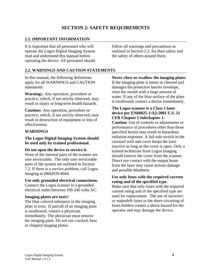
2.1. IMPORTANT INFORMATION
It is important that all personnel who will operate the Logos Digital Imaging System read and understand this manual before operating the device. All personnel should
follow all warnings and precautions as outlined in Section 2.2, for their safety and the safety of others around them.
2.2. WARNINGS AND CAUTION STATEMENTS
In this manual, the following definitions apply for all WARNINGS and CAUTION statements:
Warnings: Any operation, procedure or practice, which, if not strictly observed, may result in injury or long-term health hazards.
Cautions: Any operation, procedure or practice, which, if not strictly observed, may result in destruction of equipment or loss of effectiveness.
WARNINGS
The Logos Digital Imaging System should be used only by trained professional.
Do not open the device to service it. None of the internal parts of the scanner are user serviceable. The only user serviceable parts of the system are outlined in Section 7.2. If there is a service problem, call Logos Imaging at (866)939-4044.
Use only grounded electrical connections. Connect the Logos scanner to a grounded electrical outlet between 100-240 volts AC.
Imaging plates are toxic! The blue colored substance in the imaging plate is toxic. If part/all of an imaging plate is swallowed, contact a physician immediately. The physician must remove the imaging plate. Do not use cracked, bent or chipped imaging plates.
Never chew or swallow the imaging plates If the imaging plate is bitten or chewed and damages the protective barrier envelope, rinse the mouth with a large amount of water. If any of the blue surface of the plate is swallowed, contact a doctor immediately.
The Logos scanner is a Class 1 laser device per EN60825-1/A2:2001 U.S. 21 CFR Chapter I Subchapter J. Caution: Use of controls or adjustments or performance of procedures other than those specified herein may result in hazardous radiation exposure. A fail-safe switch in the carousel well and cover keeps the laser inactive as long as the cover is open. Only a trained technician from Logos Imaging should remove the cover from the scanner. Direct eye contact with the output beam from the laser may cause serious damage and possible blindness.
Use only fuses with the required current rating and of the specified type. Make sure that only fuses with the required current rating and of the specified type are used for replacement. The use of incorrect or makeshift fuses or the short-circuiting of fuses holders creates a shock hazard for the operator and may damage the device.

Logos Digital Imaging System 5 User Manual v 4.1.5
CAUTION STATEMENTS
Completely erase the imaging plates. Before reusing an imaging plate, lay it white surface up facing a bright light source for two (2) minutes as described in Section 5.2.
Mount the imaging plates under low light conditions. Mount the imaging plates to the carousel under low light conditions as described in Section 5.4. Exposure to direct sunlight or direct indoor lighting will erase the information stored on the imaging plate.
Do not place scanner on or next to a radiator or water source. Excessive heat or small amounts of water may damage the scanner’s electrical components.
Do not leave unscanned, exposed imaging plates in light. Leaving unscanned, exposed imaging plates in light will cause loss of image quality.
Do not scratch the imaging plates When handling the imaging plate, do not touch the active side (white) with fingernails or any sharp object that might scratch the surface. Do not lay unprotected imaging plates face down.
Logos Digital Imaging System 6 User Manual v 4.1.5
SECTION 3: PRE-INSTALLATION INFORMATION AND RECOMMENDATIONS
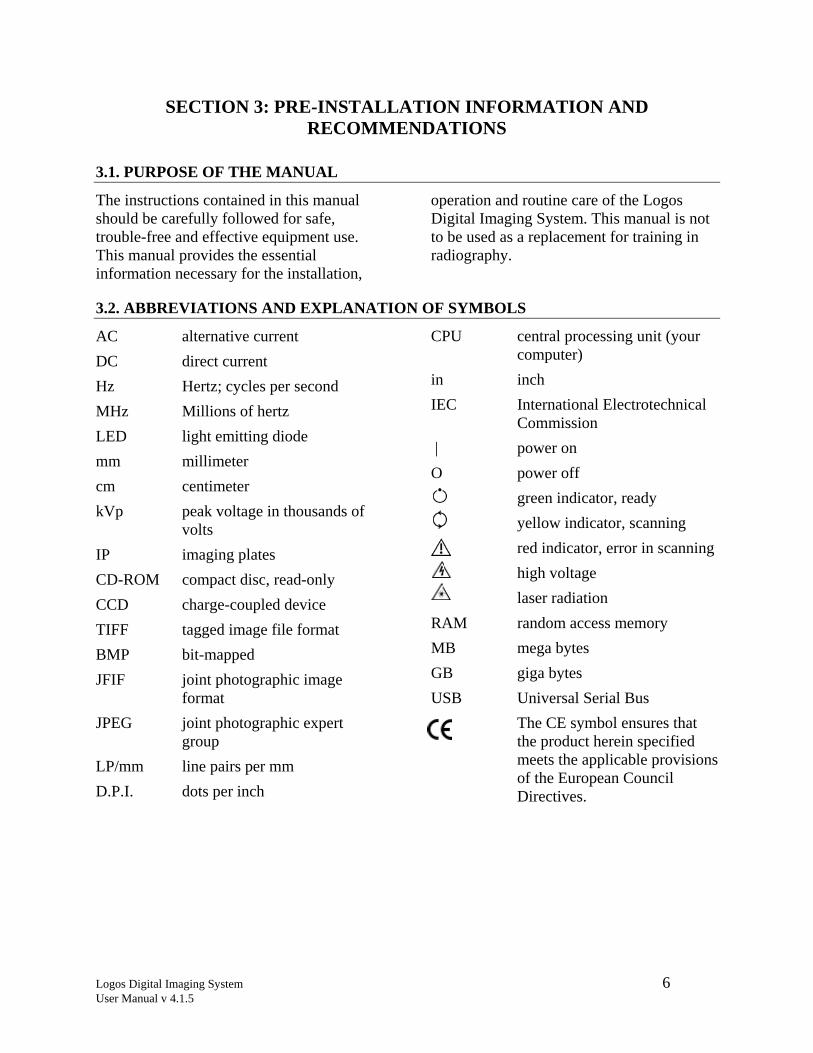
3.1. PURPOSE OF THE MANUAL
The instructions contained in this manual should be carefully followed for safe, trouble-free and effective equipment use. This manual provides the essential information necessary for the installation,
operation and routine care of the Logos Digital Imaging System. This manual is not to be used as a replacement for training in radiography.
3.2. ABBREVIATIONS AND EXPLANATION OF SYMBOLS
AC alternative current DC direct current Hz Hertz; cycles per second MHz Millions of hertz LED light emitting diode mm millimeter cm centimeter kVp peak voltage in thousands of
volts IP imaging plates CD-ROM compact disc, read-only CCD charge-coupled device TIFF tagged image file format BMP bit-mapped JFIF joint photographic image
format JPEG joint photographic expert
group LP/mm line pairs per mm D.P.I. dots per inch
CPU central processing unit (your computer)
in inch IEC International Electrotechnical
Commission | power on O power off green indicator, ready yellow indicator, scanning red indicator, error in scanning high voltage laser radiation RAM random access memory MB mega bytes GB giga bytes USB Universal Serial Bus
The CE symbol ensures that the product herein specified meets the applicable provisions of the European Council Directives.
Logos Digital Imaging System 7 User Manual v 4.1.5
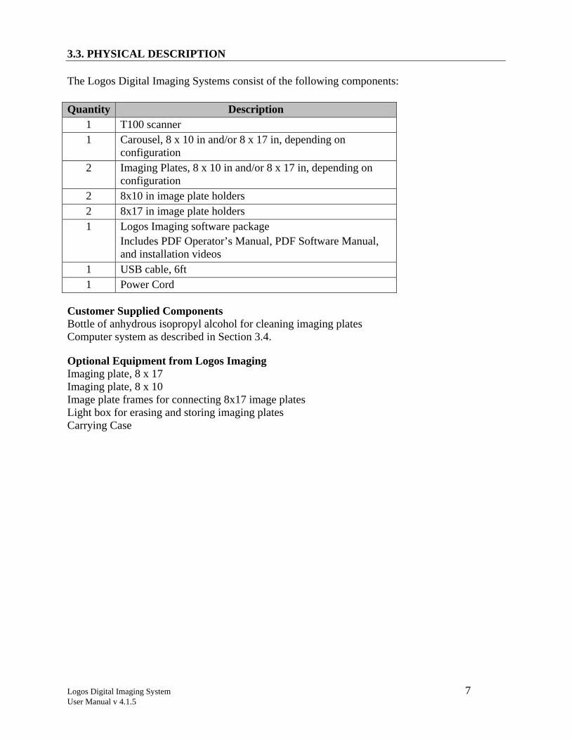
3.3. PHYSICAL DESCRIPTION
The Logos Digital Imaging Systems consist of the following components: Quantity Description
1 T100 scanner 1 Carousel, 8 x 10 in and/or 8 x 17 in, depending on
configuration 2 Imaging Plates, 8 x 10 in and/or 8 x 17 in, depending on
configuration 2 8x10 in image plate holders 2 8x17 in image plate holders 1 Logos Imaging software package
Includes PDF Operator’s Manual, PDF Software Manual, and installation videos
1 USB cable, 6ft 1 Power Cord
Customer Supplied Components Bottle of anhydrous isopropyl alcohol for cleaning imaging plates Computer system as described in Section 3.4.
Optional Equipment from Logos Imaging Imaging plate, 8 x 17 Imaging plate, 8 x 10 Image plate frames for connecting 8x17 image plates Light box for erasing and storing imaging plates Carrying Case
Logos Digital Imaging System 8 User Manual v 4.1.5
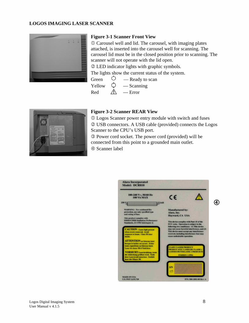
LOGOS IMAGING LASER SCANNER Figure 3-1 Scanner Front View
Carousel well and lid. The carousel, with imaging plates attached, is inserted into the carousel well for scanning. The carousel lid must be in the closed position prior to scanning. The scanner will not operate with the lid open.
LED indicator lights with graphic symbols. The lights show the current status of the system. Green — Ready to scan Yellow — Scanning Red — Error
Figure 3-2 Scanner REAR View Logos Scanner power entry module with switch and fuses USB connectors. A USB cable (provided) connects the Logos
Scanner to the CPU’s USB port. Power cord socket. The power cord (provided) will be
connected from this point to a grounded main outlet. Scanner label
1XXX DECEMBER 2002
Logos Digital Imaging System 9 User Manual v 4.1.5
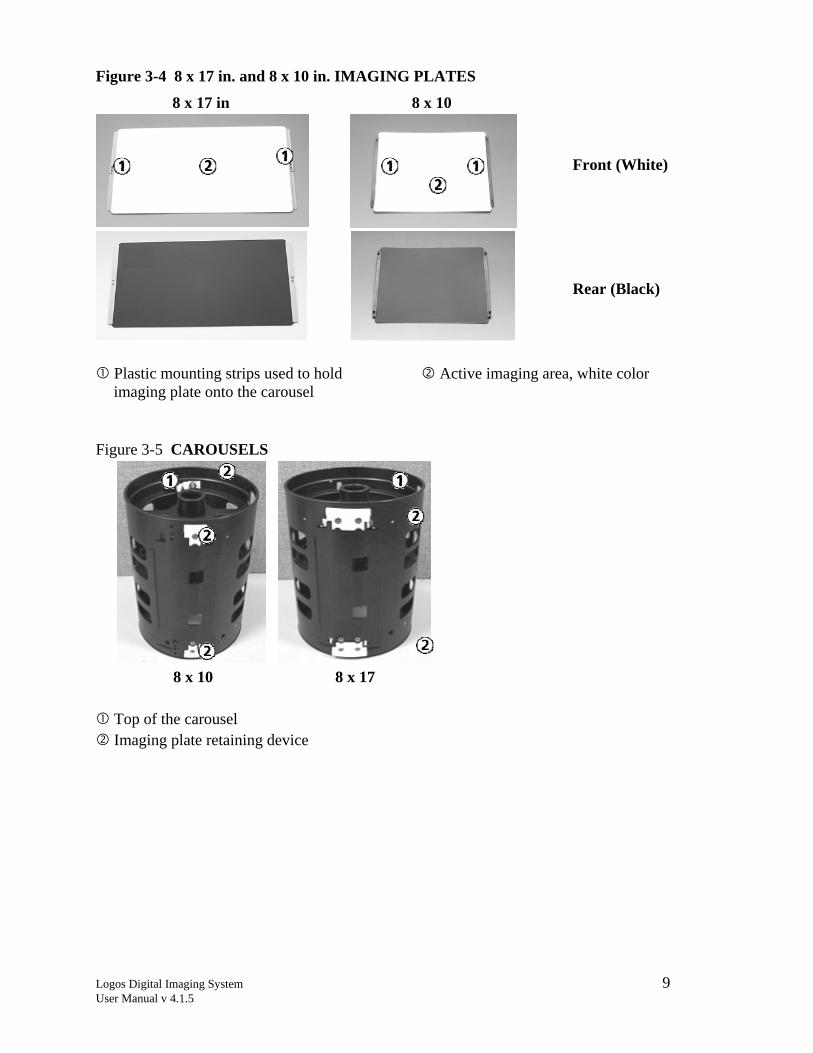
Figure 3-4 8 x 17 in. and 8 x 10 in. IMAGING PLATES
8 x 17 in 8 x 10
Plastic mounting strips used to hold imaging plate onto the carousel
Active imaging area, white color
Figure 3-5 CAROUSELS
8 x 10 8 x 17
Top of the carousel Imaging plate retaining device
Front (White)
Rear (Black)
Logos Digital Imaging System 10 User Manual v 4.1.5
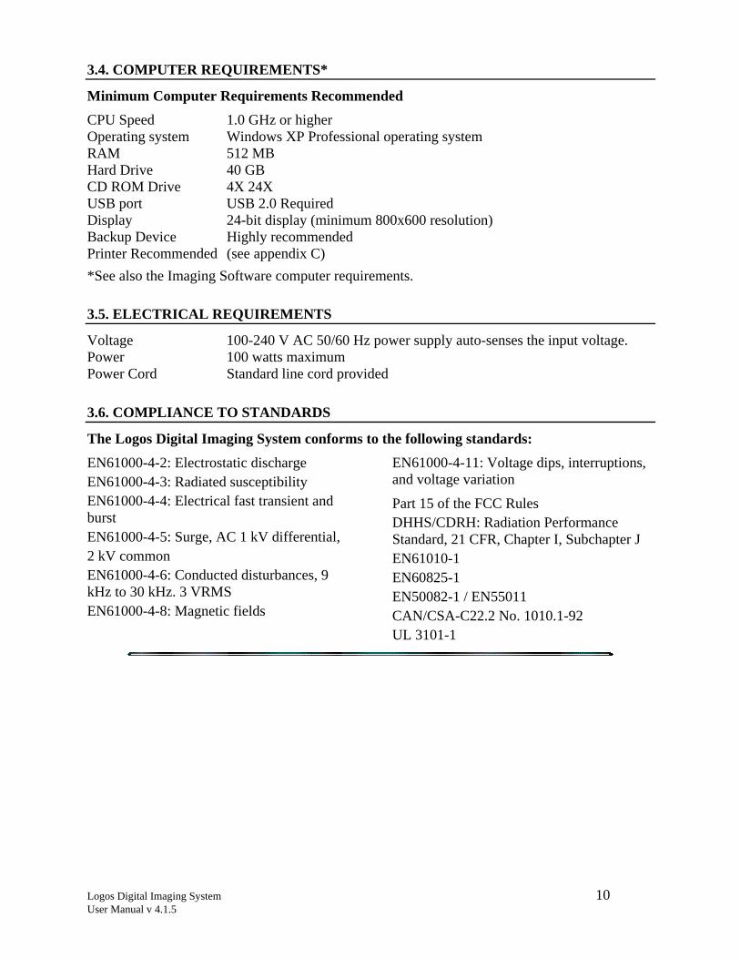
3.4. COMPUTER REQUIREMENTS*
Minimum Computer Requirements Recommended CPU Speed 1.0 GHz or higher Operating system Windows XP Professional operating system RAM 512 MB Hard Drive 40 GB CD ROM Drive 4X 24X USB port USB 2.0 Required Display 24-bit display (minimum 800x600 resolution) Backup Device Highly recommended Printer Recommended (see appendix C) *See also the Imaging Software computer requirements.
3.5. ELECTRICAL REQUIREMENTS
Voltage 100-240 V AC 50/60 Hz power supply auto-senses the input voltage. Power 100 watts maximum Power Cord Standard line cord provided
3.6. COMPLIANCE TO STANDARDS
The Logos Digital Imaging System conforms to the following standards:
EN61000-4-2: Electrostatic discharge EN61000-4-3: Radiated susceptibility EN61000-4-4: Electrical fast transient and burst EN61000-4-5: Surge, AC 1 kV differential, 2 kV common EN61000-4-6: Conducted disturbances, 9 kHz to 30 kHz. 3 VRMS EN61000-4-8: Magnetic fields
EN61000-4-11: Voltage dips, interruptions, and voltage variation
Part 15 of the FCC Rules DHHS/CDRH: Radiation Performance Standard, 21 CFR, Chapter I, Subchapter J EN61010-1 EN60825-1 EN50082-1 / EN55011 CAN/CSA-C22.2 No. 1010.1-92 UL 3101-1
Logos Digital Imaging System 11 User Manual v 4.1.5
SECTION 4: INSTALLATION
4.1. SITE SELECTION
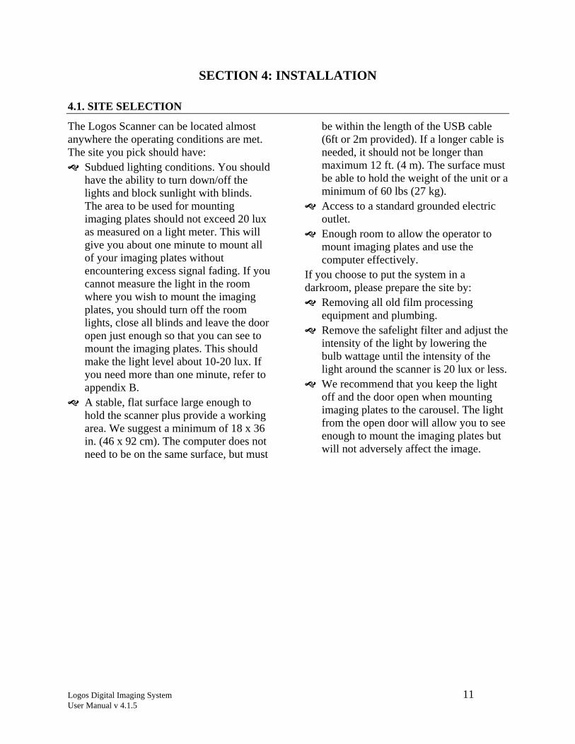
The Logos Scanner can be located almost anywhere the operating conditions are met. The site you pick should have:
Subdued lighting conditions. You should have the ability to turn down/off the lights and block sunlight with blinds. The area to be used for mounting imaging plates should not exceed 20 lux as measured on a light meter. This will give you about one minute to mount all of your imaging plates without encountering excess signal fading. If you cannot measure the light in the room where you wish to mount the imaging plates, you should turn off the room lights, close all blinds and leave the door open just enough so that you can see to mount the imaging plates. This should make the light level about 10-20 lux. If you need more than one minute, refer to appendix B.
A stable, flat surface large enough to hold the scanner plus provide a working area. We suggest a minimum of 18 x 36 in. (46 x 92 cm). The computer does not need to be on the same surface, but must
be within the length of the USB cable (6ft or 2m provided). If a longer cable is needed, it should not be longer than maximum 12 ft. (4 m). The surface must be able to hold the weight of the unit or a minimum of 60 lbs (27 kg).
Access to a standard grounded electric outlet.
Enough room to allow the operator to mount imaging plates and use the computer effectively.
If you choose to put the system in a darkroom, please prepare the site by:
Removing all old film processing equipment and plumbing.
Remove the safelight filter and adjust the intensity of the light by lowering the bulb wattage until the intensity of the light around the scanner is 20 lux or less.
We recommend that you keep the light off and the door open when mounting imaging plates to the carousel. The light from the open door will allow you to see enough to mount the imaging plates but will not adversely affect the image.
Logos Digital Imaging System 12 User Manual v 4.1.5
4.2. UNPACKING THE UNIT
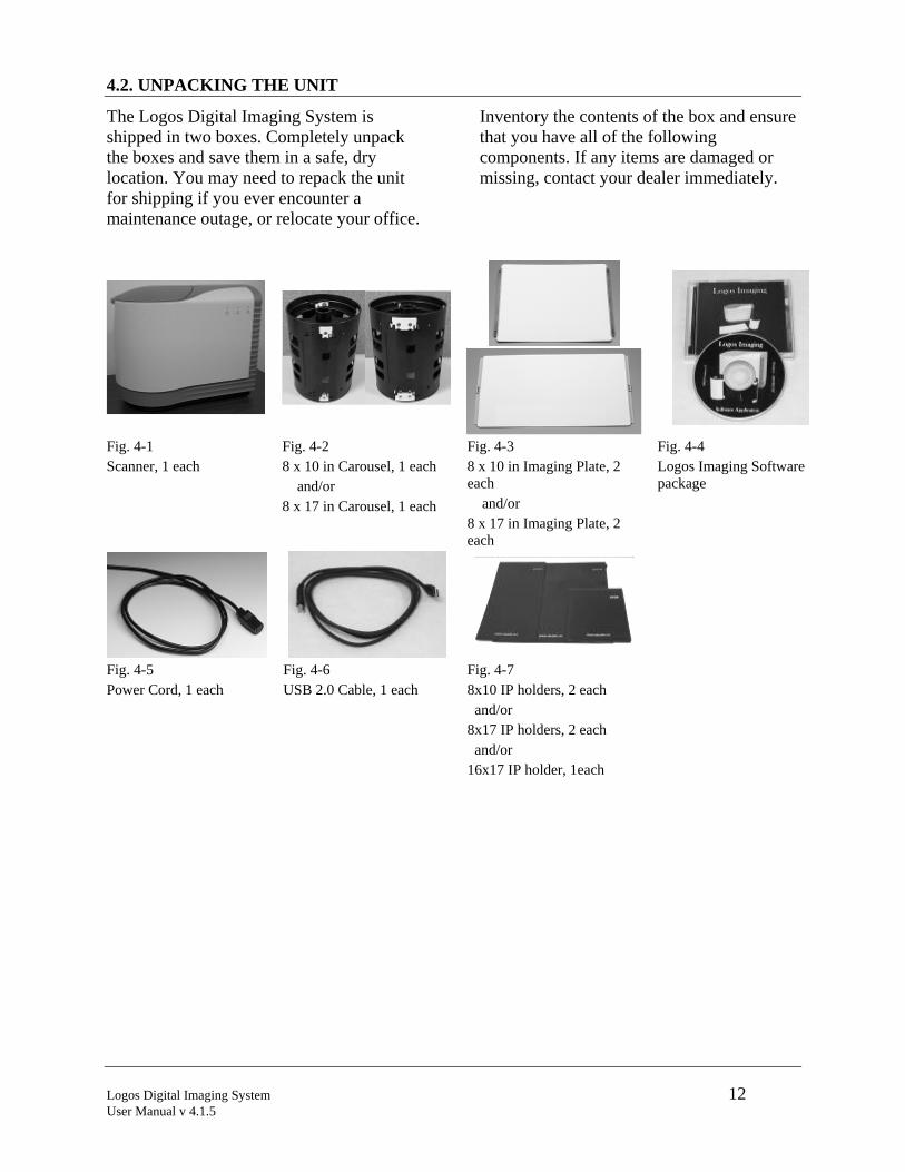
The Logos Digital Imaging System is shipped in two boxes. Completely unpack the boxes and save them in a safe, dry location. You may need to repack the unit for shipping if you ever encounter a maintenance outage, or relocate your office.
Inventory the contents of the box and ensure that you have all of the following components. If any items are damaged or missing, contact your dealer immediately.
Fig. 4-1 Scanner, 1 each
Fig. 4-2 8 x 10 in Carousel, 1 each and/or 8 x 17 in Carousel, 1 each
Fig. 4-3 8 x 10 in Imaging Plate, 2 each and/or 8 x 17 in Imaging Plate, 2 each
Fig. 4-4 Logos Imaging Software package
Fig. 4-5 Power Cord, 1 each
Fig. 4-6 USB 2.0 Cable, 1 each
Fig. 4-7 8x10 IP holders, 2 each and/or 8x17 IP holders, 2 each and/or 16x17 IP holder, 1each
Logos Digital Imaging System 13 User Manual v 4.1.5
4.3. LOADING THE LOGOS DRIVER SOFTWARE
Do not plug in or turn on the Logos scanner before installing the Logos Imaging software. The Logos system drivers are loaded automatically during Logos Software installation.
WARNING: THE LOGOS SYSTEM MUST NOT BE INSTALLED ON THE NETWORK SERVER
4.4. HARDWARE SETUP AND CONNECTIONS
Before you start the hardware setup, ensure that you have an acceptable computer as outlined in Section 3.4 and that the Logos Software application is installed on your computer. The computer must have a USB 2.0 port available. Step 1: Pick a location using the guidelines from 4.1. Step 2: Set up the computer and monitor per the manufacturer’s recommendations. Use an
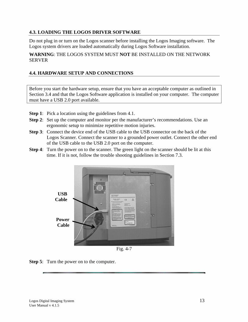
ergonomic setup to minimize repetitive motion injuries. Step 3: Connect the device end of the USB cable to the USB connector on the back of the
Logos Scanner. Connect the scanner to a grounded power outlet. Connect the other end of the USB cable to the USB 2.0 port on the computer.
Step 4: Turn the power on to the scanner. The green light on the scanner should be lit at this time. If it is not, follow the trouble shooting guidelines in Section 7.3.
Fig. 4-7
Step 5: Turn the power on to the computer.
USB Cable
Power Cable
Logos Digital Imaging System 14 User Manual v 4.1.5
SECTION 5: SYSTEM OPERATING INSTRUCTIONS
5.1. PREPARING YOUR CURRENT X-RAY EQUIPMENT
The Logos Digital Imaging System produces x-ray images of high quality and low noise. More details on how this technology works can be found in appendix A. Almost any x-ray unit can be used with the Logos system. There is no need to purchase a new one. The imaging plates can produce an excellent
image over a wide range of exposures. With the Logos system, it is possible to get high-quality images at the same exposure time you use for x-ray film. This is a great benefit to you because it means that it will be more difficult to over- or under-expose an image.
5.2. ERASE THE IMAGING PLATE
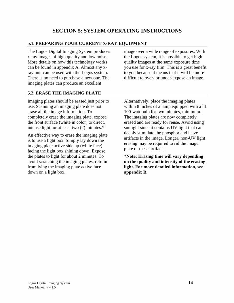
Imaging plates should be erased just prior to use. Scanning an imaging plate does not erase all the image information. To completely erase the imaging plate, expose the front surface (white in color) to direct, intense light for at least two (2) minutes.*
An effective way to erase the imaging plate is to use a light box. Simply lay down the imaging plate active side up (white face) facing the light box shining down. Expose the plates to light for about 2 minutes. To avoid scratching the imaging plates, refrain from lying the imaging plate active face down on a light box.
Alternatively, place the imaging plates within 8 inches of a lamp equipped with a lit 100-watt bulb for two minutes, minimum. The imaging plates are now completely erased and are ready for reuse. Avoid using sunlight since it contains UV light that can deeply stimulate the phosphor and leave artifacts in the image. Longer, non-UV light erasing may be required to rid the image plate of these artifacts.
*Note: Erasing time will vary depending on the quality and intensity of the erasing light. For more detailed information, see appendix B.
Logos Digital Imaging System 15 User Manual v 4.1.5
5.3. TAKING AN X-RAY
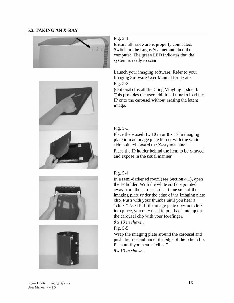
Fig. 5-1 Ensure all hardware is properly connected. Switch on the Logos Scanner and then the computer. The green LED indicates that the system is ready to scan
Launch your imaging software. Refer to your Imaging Software User Manual for details Fig. 5-2 (Optional) Install the Cling Vinyl light shield. This provides the user additional time to load the IP onto the carousel without erasing the latent image.
Fig. 5-3 Place the erased 8 x 10 in or 8 x 17 in imaging plate into an image plate holder with the white side pointed toward the X-ray machine. Place the IP holder behind the item to be x-rayed and expose in the usual manner.
Fig. 5-4 In a semi-darkened room (see Section 4.1), open the IP holder. With the white surface pointed away from the carousel, insert one side of the imaging plate under the edge of the imaging plate clip. Push with your thumbs until you hear a “click.” NOTE: If the image plate does not click into place, you may need to pull back and up on the carousel clip with your forefinger. 8 x 10 in shown. Fig. 5-5 Wrap the imaging plate around the carousel and push the free end under the edge of the other clip. Push until you hear a “click.” 8 x 10 in shown.
Logos Digital Imaging System 16 User Manual v 4.1.5
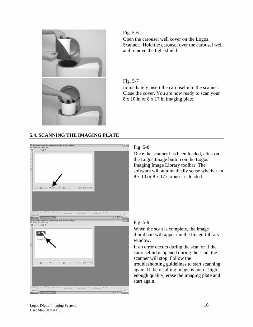
Fig. 5-6 Open the carousel well cover on the Logos Scanner. Hold the carousel over the carousel well and remove the light shield.
Fig. 5-7 Immediately insert the carousel into the scanner. Close the cover. You are now ready to scan your 8 x 10 in or 8 x 17 in imaging plate.
5.4. SCANNING THE IMAGING PLATE
Fig. 5-8 Once the scanner has been loaded, click on the Logos Image button on the Logos Imaging Image Library toolbar. The software will automatically sense whether an 8 x 10 or 8 x 17 carousel is loaded.
Fig. 5-9 When the scan is complete, the image thumbnail will appear in the Image Library window. If an error occurs during the scan or if the carousel lid is opened during the scan, the scanner will stop. Follow the troubleshooting guidelines to start scanning again. If the resulting image is not of high enough quality, erase the imaging plate and start again.
Logos Digital Imaging System 17 User Manual v 4.1.5
5.5. TURNING OFF THE LOGOS SYSTEM
The Logos Scanner Digital Imaging System is designed to be left on continuously when used in a laboratory setting. The laser is only operational while the unit is actually scanning. If you wish to turn the system off, use the following procedure. 1. Wait until any scan in progress is
complete and the green light is on. 2. Save any changes you have made and
close down the imaging software. To
protect your data, frequently back-up your files.
3. Turn off all computer components following any instructions from the manufacturer.
4. Turn the power switch on the back of the scanner, or the power switch on the power box in the Pelican case, to the “Off” position.

Logos Digital Imaging System 18 User Manual v 4.1.5
SECTION 6: SOFTWARE OPERATING INSTRUCTIONS
Logos Imaging software can capture digital x-ray images from the Logos systems. Please refer to the Logos Imaging software user’s manual or online help file for detailed instructions.
Logos Digital Imaging System 19 User Manual v 4.1.5
SECTION 7: MAINTENANCE PROCEDURES
The Logos Digital Imaging System is designed for many years of trouble-free operation. It is manufactured from the highest quality components to ensure excellent performance. Maintenance that can be performed by the operator is minimal.
7.1. CLEANING THE SYSTEM
Cleaning the Scanner Turn off the Logos Scanner, as described in Section 5.5, before cleaning. Wipe the outside surfaces with a paper towel dampened with a cold sterilant solution or household, non-abrasive cleaner (window cleaner works well). DO NOT SPRAY OR SOAK THE SCANNER. Wipe the inside of the carousel well with a very slightly damp cloth. Be careful not to allow running or dripping solvents into the Logos Scanner. This could cause damage to the electronics inside. Allow to air dry before plugging in or turning back on.
Cleaning Imaging Plates Imaging plates should be handled carefully. For the best images, take care not to scratch
them and keep them dust-free. Use the following procedure to clean them:
1. Use lint-free, 100% cotton gauze (not cotton balls). Gently wipe the cotton gauze over the dry imaging plate surface. Wipe back and forth and then in a circular motion.
2. To clean any remaining stains, dampen the gauze in anhydrous isopropyl alcohol and wipe using the same motion as above.
3. Completely dry the surface by wiping with another piece of cotton gauze. Ensure that the imaging plate is completely dry before use.
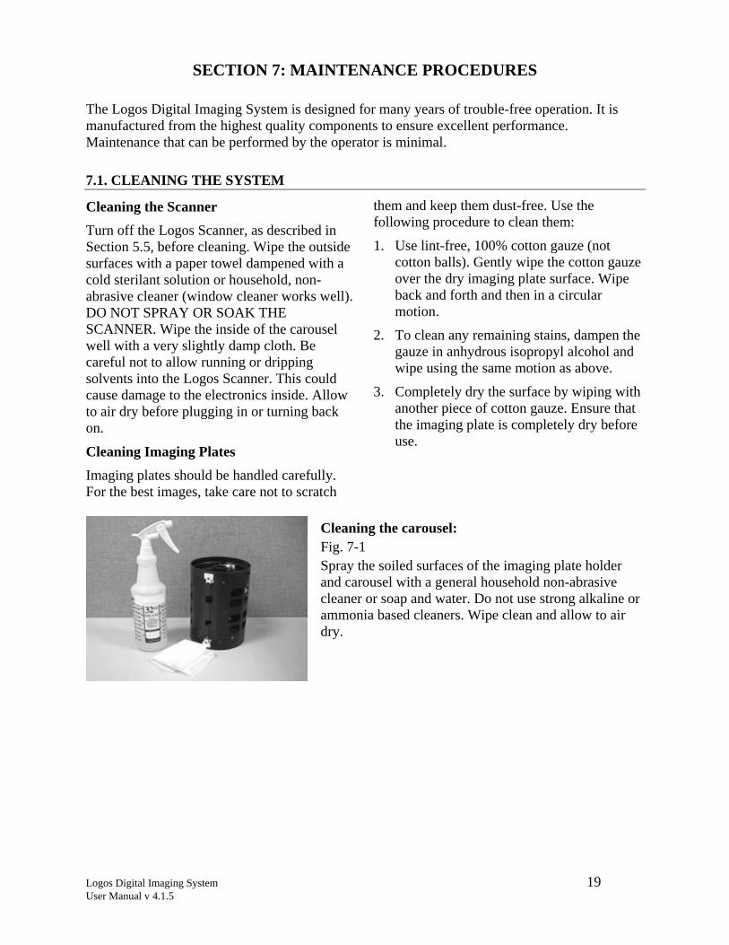
Cleaning the carousel: Fig. 7-1 Spray the soiled surfaces of the imaging plate holder and carousel with a general household non-abrasive cleaner or soap and water. Do not use strong alkaline or ammonia based cleaners. Wipe clean and allow to air dry.
Logos Digital Imaging System 20 User Manual v 4.1.5
7.2. OPERATOR MAINTENANCE
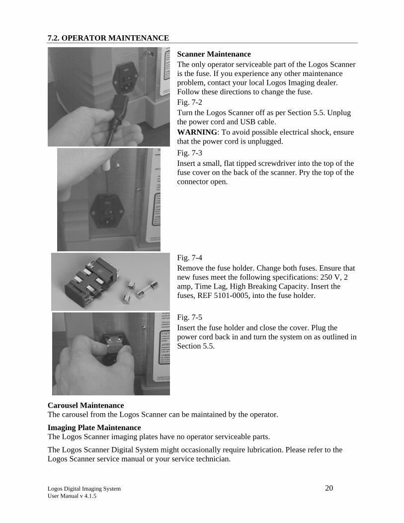
Scanner Maintenance The only operator serviceable part of the Logos Scanner is the fuse. If you experience any other maintenance problem, contact your local Logos Imaging dealer. Follow these directions to change the fuse. Fig. 7-2 Turn the Logos Scanner off as per Section 5.5. Unplug the power cord and USB cable. WARNING: To avoid possible electrical shock, ensure that the power cord is unplugged.
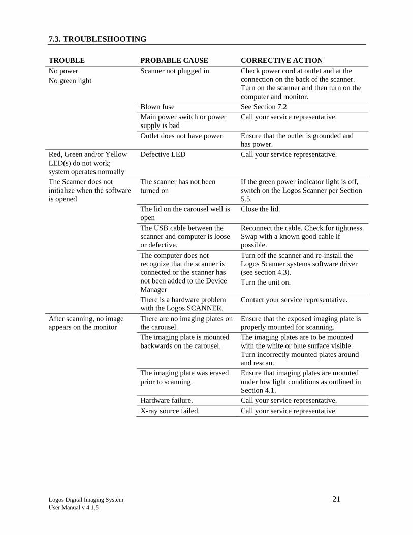
Fig. 7-3 Insert a small, flat tipped screwdriver into the top of the fuse cover on the back of the scanner. Pry the top of the connector open.
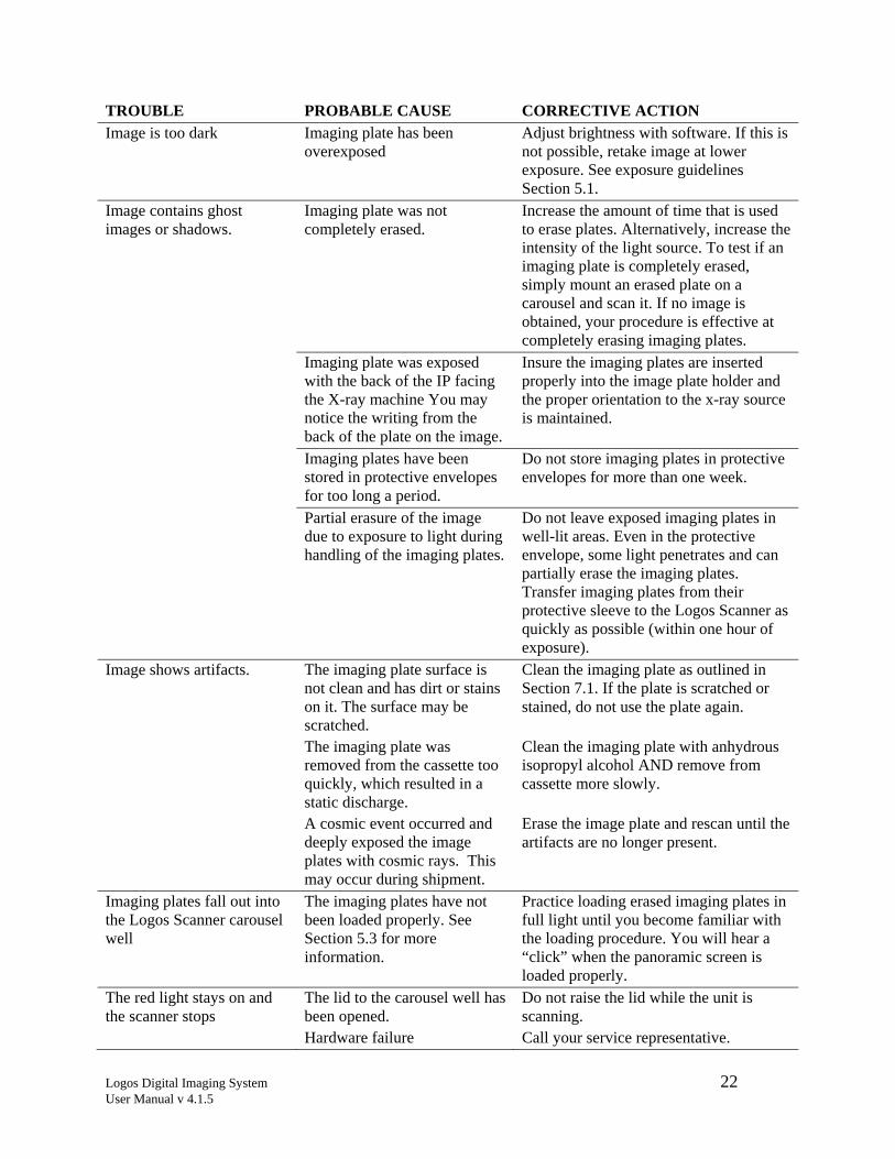
Fig. 7-4 Remove the fuse holder. Change both fuses. Ensure that new fuses meet the following specifications: 250 V, 2 amp, Time Lag, High Breaking Capacity. Insert the fuses, REF 5101-0005, into the fuse holder.
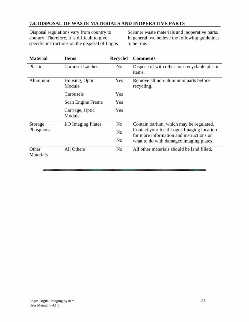
Fig. 7-5 Insert the fuse holder and close the cover. Plug the power cord back in and turn the system on as outlined in Section 5.5.
Carousel Maintenance The carousel from the Logos Scanner can be maintained by the operator.
Imaging Plate Maintenance The Logos Scanner imaging plates have no operator serviceable parts.
The Logos Scanner Digital System might occasionally require lubrication. Please refer to the Logos Scanner service manual or your service technician.
Logos Digital Imaging System 21 User Manual v 4.1.5
7.3. TROUBLESHOOTING
TROUBLE PROBABLE CAUSE CORRECTIVE ACTION No power No green light
Scanner not plugged in Check power cord at outlet and at the connection on the back of the scanner. Turn on the scanner and then turn on the computer and monitor.
Blown fuse See Section 7.2 Main power switch or power
supply is bad Call your service representative.
Outlet does not have power Ensure that the outlet is grounded and has power.
Red, Green and/or Yellow LED(s) do not work; system operates normally
Defective LED Call your service representative.
The Scanner does not initialize when the software is opened
The scanner has not been turned on
If the green power indicator light is off, switch on the Logos Scanner per Section 5.5.
The lid on the carousel well is open
Close the lid.
The USB cable between the scanner and computer is loose or defective.
Reconnect the cable. Check for tightness. Swap with a known good cable if possible.
The computer does not recognize that the scanner is connected or the scanner has not been added to the Device Manager
Turn off the scanner and re-install the Logos Scanner systems software driver (see section 4.3). Turn the unit on.
There is a hardware problem with the Logos SCANNER.
Contact your service representative.
After scanning, no image appears on the monitor
There are no imaging plates on the carousel.
Ensure that the exposed imaging plate is properly mounted for scanning.
The imaging plate is mounted backwards on the carousel.
The imaging plates are to be mounted with the white or blue surface visible. Turn incorrectly mounted plates around and rescan.
The imaging plate was erased prior to scanning.
Ensure that imaging plates are mounted under low light conditions as outlined in Section 4.1.
Hardware failure. Call your service representative. X-ray source failed. Call your service representative.
Logos Digital Imaging System 22 User Manual v 4.1.5
TROUBLE PROBABLE CAUSE CORRECTIVE ACTION Image is too dark Imaging plate has been
overexposed Adjust brightness with software. If this is not possible, retake image at lower exposure. See exposure guidelines Section 5.1.
Image contains ghost images or shadows.
Imaging plate was not completely erased.
Increase the amount of time that is used to erase plates. Alternatively, increase the intensity of the light source. To test if an imaging plate is completely erased, simply mount an erased plate on a carousel and scan it. If no image is obtained, your procedure is effective at completely erasing imaging plates.
Imaging plate was exposed with the back of the IP facing the X-ray machine You may notice the writing from the back of the plate on the image.
Insure the imaging plates are inserted properly into the image plate holder and the proper orientation to the x-ray source is maintained.
Imaging plates have been stored in protective envelopes for too long a period.
Do not store imaging plates in protective envelopes for more than one week.
Partial erasure of the image due to exposure to light during handling of the imaging plates.
Do not leave exposed imaging plates in well-lit areas. Even in the protective envelope, some light penetrates and can partially erase the imaging plates. Transfer imaging plates from their protective sleeve to the Logos Scanner as quickly as possible (within one hour of exposure).
Image shows artifacts. The imaging plate surface is not clean and has dirt or stains on it. The surface may be scratched.
Clean the imaging plate as outlined in Section 7.1. If the plate is scratched or stained, do not use the plate again.
The imaging plate was removed from the cassette too quickly, which resulted in a static discharge.
Clean the imaging plate with anhydrous isopropyl alcohol AND remove from cassette more slowly.
A cosmic event occurred and deeply exposed the image plates with cosmic rays. This may occur during shipment.
Erase the image plate and rescan until the artifacts are no longer present.
Imaging plates fall out into the Logos Scanner carousel well
The imaging plates have not been loaded properly. See Section 5.3 for more information.
Practice loading erased imaging plates in full light until you become familiar with the loading procedure. You will hear a “click” when the panoramic screen is loaded properly.
The red light stays on and the scanner stops
The lid to the carousel well has been opened.
Do not raise the lid while the unit is scanning.
Hardware failure Call your service representative.
Logos Digital Imaging System 23 User Manual v 4.1.5
7.4. DISPOSAL OF WASTE MATERIALS AND INOPERATIVE PARTS
Disposal regulations vary from country to country. Therefore, it is difficult to give specific instructions on the disposal of Logos
Scanner waste materials and inoperative parts. In general, we believe the following guidelines to be true.
Material Items Recycle? Comments
Plastic Carousel Latches No Dispose of with other non-recyclable plastic items.
Aluminum Housing, Optic Module
Yes Remove all non-aluminum parts before recycling.
Carousels Yes
Scan Engine Frame Yes
Carriage, Optic Module
Yes
Storage Phosphors
I/O Imaging Plates No
No
No
Contain barium, which may be regulated. Contact your local Logos Imaging location for more information and instructions on what to do with damaged imaging plates.
Other Materials
All Others No All other materials should be land filled.
Logos Digital Imaging System 24 User Manual v 4.1.5
SECTION 8: STORAGE AND SHIPMENT
8.1. STORAGE
If the system is to be stored for a long period of time, pack the unit in its original carton. While in storage, keep at moderate temperatures and protect against moisture and humidity. When you are ready to use the
system again, unpack it and allow the scanner to come back to room temperature. Then, follow the guidelines outlined in Section 5.
8.2. SHIPMENT
The Logos Digital Imaging System is designed to be shipped in its carrying case or original shipping container by normal commercial carriers. Ensure that the carousel has been removed from the scanner and that the carousel well is empty.
If the system is to be moved long distances or under adverse conditions, it should be protected by wrapping the Logos scanner in
a plastic bag before putting it in the carrying case or original packing materials. (Original packing materials are available through Logos Imaging by request.)
If you are shipping the scanner, it is necessary to park the optics module in the center of travel prior to shipment. Contact your Logos Imaging dealer for details.
Logos Digital Imaging System 25 User Manual v 4.1.5
SECTION 9: TECHNICAL SPECIFICATIONS
9.1. SPECIFICATIONS
Logos Scanner Height 39.4 cm 15.5 in Width 49.3 cm 19.4 in Depth 27.4 cm 10.8 in Weight (empty) 16 kg 35 lbs Interface Cables USB 2.0 cables Voltage 100-240 V AC Frequency 50/60 Hz Power 100 watts max. Laser Classification Compliance per DHHS Radiation Performance
Standards 21 CFR, Ch I, Subch. J+EN60825-1/A2:2001 Class 1 Laser Device
Storage and Shipping Conditions -40° to 70°C (-40° to 158°F) Logos Imaging Plates Dimensions: 8 x 10 in (20.3 cm x 25.4 cm) and 8 x 17 in (20.3 x
43.2 cm) Resolution at 300 DPI: 85 micron square pixels, approximately 4 lp/mm Resolution at 150 DPI: 170 micron square pixels, approximately 2 lp/mm Recommended Dose: Equal to standard systems equipped with rare-earth
intensifying screens (400 speed) Storage: Store in their plastic shipping envelope
Logos Digital Imaging System 26 User Manual v 4.1.5
SECTION 10: WARRANTY STATEMENT
Logos Scanner The scanner and carousels are warranted against defects arising from faulty materials or workmanship for three (3) years from date of purchase. Parts will be repaired or replaced at our option. The Logos Scanner and Carousels must be installed and
operated in accordance with the Logos Imaging written instructions furnished with the unit. Please fill out the warranty registration card (appendix D) and mail to Logos Imaging as instructed.
Logos Imaging Plates The Logos Imaging Plates are designed expressly for use with the Logos scanner. Logos Imaging Plates will be replaced if defective in manufacturing or packaging only. With proper handling, Logos Imaging
Plates are designed for years of effective use. They can, however, be damaged if folded, creased, scratched or dented, and, therefore no additional warranty is provided.
Software and Technical Support
The Logos Scanner includes lifetime maintenance on base Logos Imaging Security software and lifetime telephone tech support by contacting Logos Imaging at
(866) 939-4044. The software maintenance plan does not include free upgrades for third-party add-ins.
Warranty Service Center
Logos Imaging LLC 1440 NW 11th Street Richmond, IN 47374 (765) 939-4044
Logos Digital Imaging System 27 User Manual v 4.1.5
Appendix A: Storage Phosphor Technology
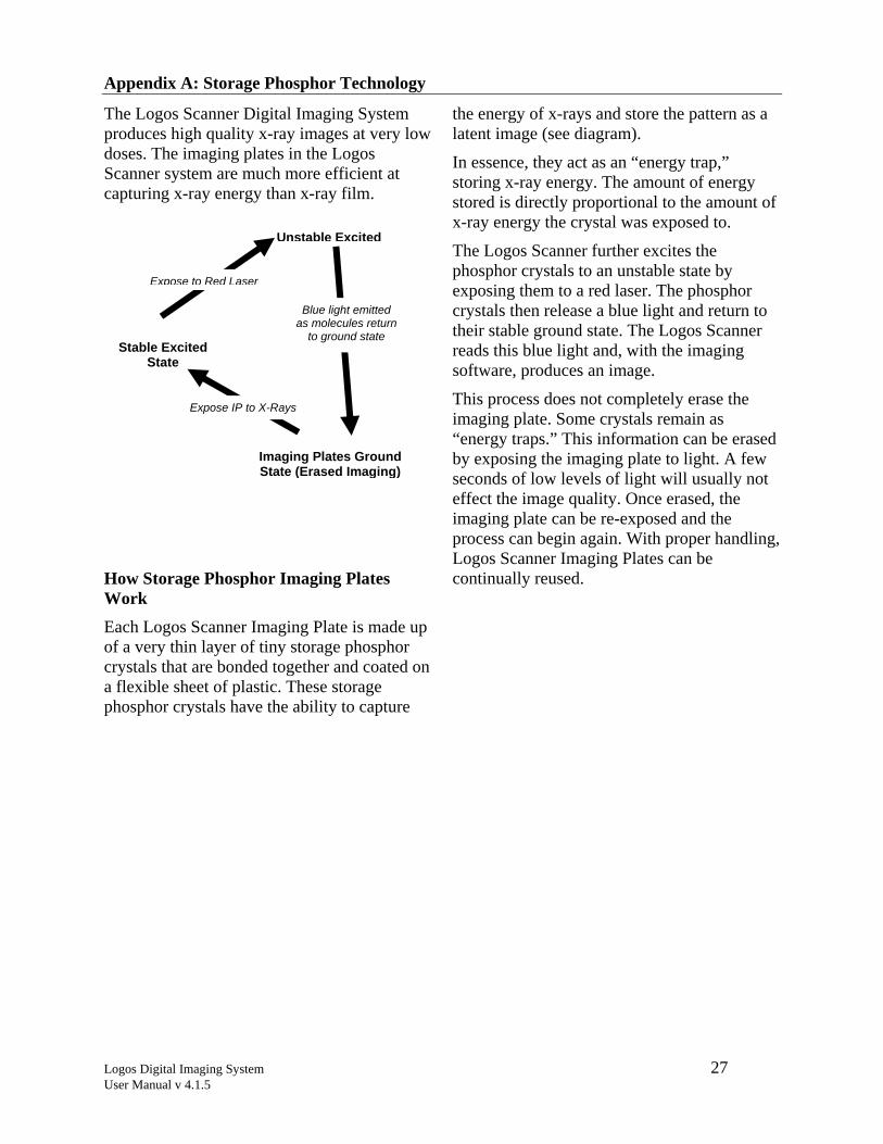
The Logos Scanner Digital Imaging System produces high quality x-ray images at very low doses. The imaging plates in the Logos Scanner system are much more efficient at capturing x-ray energy than x-ray film.
How Storage Phosphor Imaging Plates Work Each Logos Scanner Imaging Plate is made up of a very thin layer of tiny storage phosphor crystals that are bonded together and coated on a flexible sheet of plastic. These storage phosphor crystals have the ability to capture
the energy of x-rays and store the pattern as a latent image (see diagram).
In essence, they act as an “energy trap,” storing x-ray energy. The amount of energy stored is directly proportional to the amount of x-ray energy the crystal was exposed to.
The Logos Scanner further excites the phosphor crystals to an unstable state by exposing them to a red laser. The phosphor crystals then release a blue light and return to their stable ground state. The Logos Scanner reads this blue light and, with the imaging software, produces an image.
This process does not completely erase the imaging plate. Some crystals remain as “energy traps.” This information can be erased by exposing the imaging plate to light. A few seconds of low levels of light will usually not effect the image quality. Once erased, the imaging plate can be re-exposed and the process can begin again. With proper handling, Logos Scanner Imaging Plates can be continually reused.
Stable Excited State
Unstable Excited
Imaging Plates Ground State (Erased Imaging)
Blue light emitted as molecules return
to ground state
Expose to Red Laser
Expose IP to X-Rays

Logos Digital Imaging System 28 User Manual v 4.1.5
Appendix B: Lighting Conditions for Handling or Erasing Imaging Plates
Without light, storage phosphor imaging would not work. The red light from the laser scanner excites the exposed imaging plates, causing them to emit blue light. After your computer interprets the blue light and changes it into a digital image, light is used to erase the residual information from the imaging plate.
Between x-ray exposure and scanning, however, one must be careful handling the imaging plates. An imaging plate should never be removed from its protective sleeve or cassette and exposed to a strong source of light. This act would erase the latent image from the plate. Therefore, you must load imaging plates onto the carousel under controlled lighting conditions. The recommendations below have been developed to ensure that you obtain excellent image quality.
Recommendations on Lighting Conditions for Loading Carousels
Fluorescent Lights If loading can be accomplished in less than 60 seconds, the fluorescent lighting in the
area should not exceed 20 lux. If loading will take longer than 60 seconds, the room conditions need to be darker. At 10 lux, the operator has about 5 minutes to accomplish loading.
Incandescent Lighting Incandescent lighting is about half as efficient as fluorescent lighting at fading imaging plates. Here, again, we recommend lighting conditions of around 20 lux. Under incandescent lighting, however, you have about 2 minutes to complete the loading process. If it takes longer than 2 minutes, decrease the amount of light to 10 lux.
Sunlight Sunlight is the most efficient light for fading imaging plates. Additionally, it is very difficult to judge the intensity of sunlight. Loading carousels under sunlight is not recommended.
If you cannot darken your mounting area to 20 lux or less, contact your local Logos Imaging representative for suggested mounting times.
Logos Digital Imaging System 29 User Manual v 4.1.5
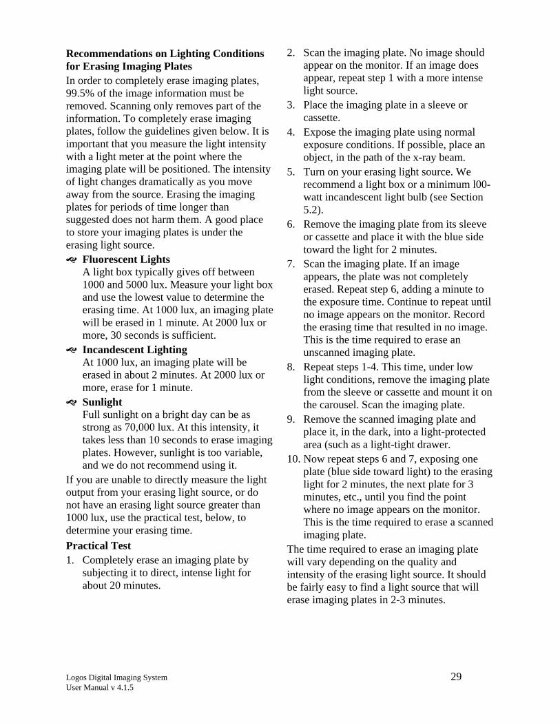
Recommendations on Lighting Conditions for Erasing Imaging Plates In order to completely erase imaging plates, 99.5% of the image information must be removed. Scanning only removes part of the information. To completely erase imaging plates, follow the guidelines given below. It is important that you measure the light intensity with a light meter at the point where the imaging plate will be positioned. The intensity of light changes dramatically as you move away from the source. Erasing the imaging plates for periods of time longer than suggested does not harm them. A good place to store your imaging plates is under the erasing light source.
Fluorescent Lights A light box typically gives off between 1000 and 5000 lux. Measure your light box and use the lowest value to determine the erasing time. At 1000 lux, an imaging plate will be erased in 1 minute. At 2000 lux or more, 30 seconds is sufficient.
Incandescent Lighting At 1000 lux, an imaging plate will be erased in about 2 minutes. At 2000 lux or more, erase for 1 minute.
Sunlight Full sunlight on a bright day can be as strong as 70,000 lux. At this intensity, it takes less than 10 seconds to erase imaging plates. However, sunlight is too variable, and we do not recommend using it.
If you are unable to directly measure the light output from your erasing light source, or do not have an erasing light source greater than 1000 lux, use the practical test, below, to determine your erasing time. Practical Test 1. Completely erase an imaging plate by
subjecting it to direct, intense light for about 20 minutes.
2. Scan the imaging plate. No image should appear on the monitor. If an image does appear, repeat step 1 with a more intense light source.
3. Place the imaging plate in a sleeve or cassette.
4. Expose the imaging plate using normal exposure conditions. If possible, place an object, in the path of the x-ray beam.
5. Turn on your erasing light source. We recommend a light box or a minimum l00-watt incandescent light bulb (see Section 5.2).
6. Remove the imaging plate from its sleeve or cassette and place it with the blue side toward the light for 2 minutes.
7. Scan the imaging plate. If an image appears, the plate was not completely erased. Repeat step 6, adding a minute to the exposure time. Continue to repeat until no image appears on the monitor. Record the erasing time that resulted in no image. This is the time required to erase an unscanned imaging plate.
8. Repeat steps 1-4. This time, under low light conditions, remove the imaging plate from the sleeve or cassette and mount it on the carousel. Scan the imaging plate.
9. Remove the scanned imaging plate and place it, in the dark, into a light-protected area (such as a light-tight drawer.
10. Now repeat steps 6 and 7, exposing one plate (blue side toward light) to the erasing light for 2 minutes, the next plate for 3 minutes, etc., until you find the point where no image appears on the monitor. This is the time required to erase a scanned imaging plate.
The time required to erase an imaging plate will vary depending on the quality and intensity of the erasing light source. It should be fairly easy to find a light source that will erase imaging plates in 2-3 minutes.
Logos Digital Imaging System 30 User Manual v 4.1.5
Appendix C: Optional PrinterBecause printer technology is constantly evolving, we can only suggest a list of suitable technical requirements for printers.
To interface with the PC, the printer must have a digital input and not a video (analog) input.
Inkjet printers Black and white or color hard copy. Printers should have a minimum of 600 dpi resolution and pseudo-randomic dithering. Using the standard Windows® drivers allows the use of
the same printer for all other Windows applications (word processing, etc.).
The Epson Stylus Photo product line is suitable for printing moderate to good quality images. We recommend using the photographic quality glossy paper and printing on the highest resolution setting available.
Dye Sublimation printers Advised whenever high printing quality is required.
Logos Digital Imaging System 31 User Manual v 4.1.5
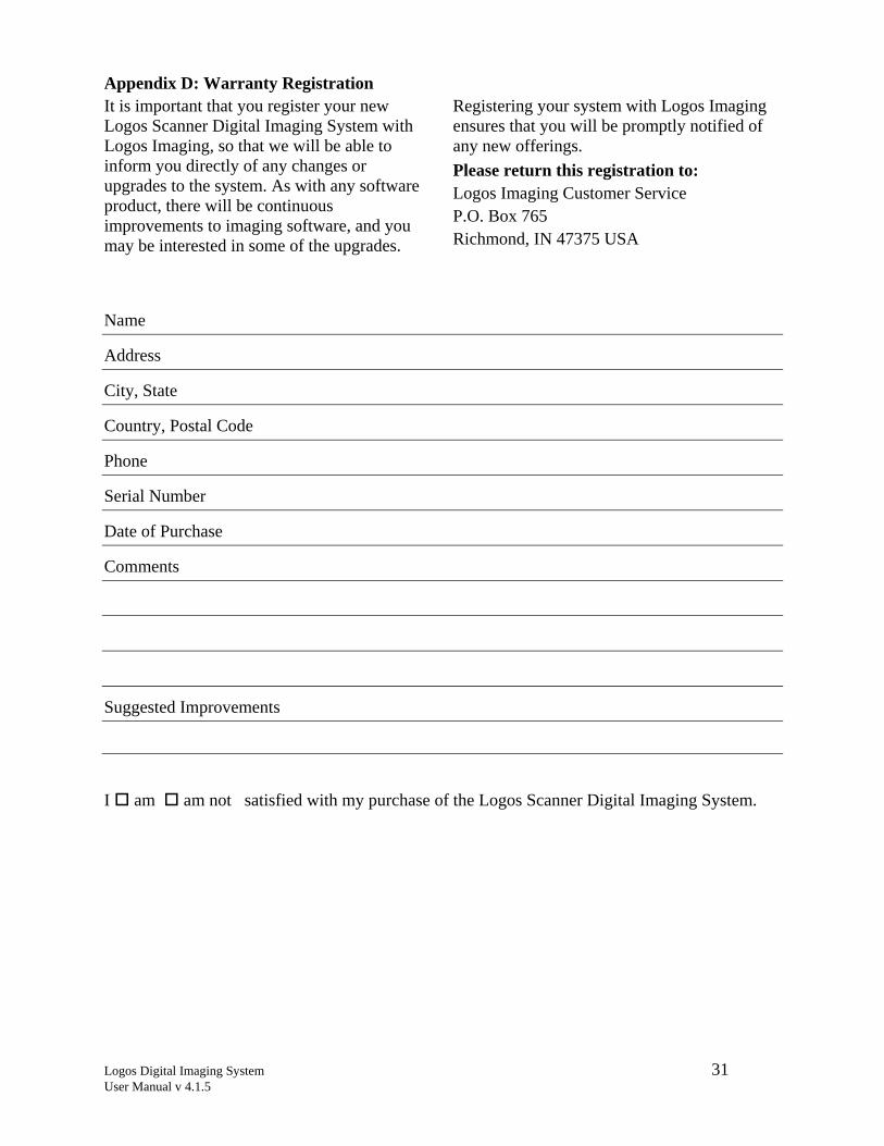
Appendix D: Warranty RegistrationIt is important that you register your new Logos Scanner Digital Imaging System with Logos Imaging, so that we will be able to inform you directly of any changes or upgrades to the system. As with any software product, there will be continuous improvements to imaging software, and you may be interested in some of the upgrades.
Registering your system with Logos Imaging ensures that you will be promptly notified of any new offerings. Please return this registration to: Logos Imaging Customer Service P.O. Box 765 Richmond, IN 47375 USA
Name
Address
City, State
Country, Postal Code
Phone
Serial Number
Date of Purchase
Comments
Suggested Improvements
I am am not satisfied with my purchase of the Logos Scanner Digital Imaging System.