logo!powerucc.colorado.edu/siemens/a5e40912965-1-76_manual_sitop-logo… · manual logo!power 5...
TRANSCRIPT
___________________
___________________
___________________
___________________
___________________
___________________
___________________
___________________
___________________
___________________
___________________
___________________
SITOP power supply
LOGO!Power
Manual
LOGO!Power 5 V/3 A 6EP3310-6SB00-0AY0 LOGO!Power 5 V/6.3 A 6EP3311-6SB00-0AY0 LOGO!Power 12 V/0.9 A 6EP3320-6SB00-0AY0 LOGO!Power 12 V/1.9 A 6EP3321-6SB00-0AY0 LOGO!Power 12 V/4.5 A 6EP3322-6SB00-0AY0 LOGO!Power 15 V/1.9 A 6EP3321-6SB10-0AY0 LOGO!Power 15 V/4 A 6EP3322-6SB10-0AY0 LOGO!Power 24 V/0.6 A 6EP3330-6SB00-0AY0 LOGO!Power 24 V/1.3 A 6EP3331-6SB00-0AY0 LOGO!Power 24 V/2.5 A 6EP3332-6SB00-0AY0 LOGO!Power 24 V/4 A 6EP3333-6SB00-0AY0 06.2017 A5E40912965-1-76
Overview
Safety instructions 1
Description, device design, dimension drawing
2
Mounting/removal 3
Mounting position, mounting clearances
4
Installation 5
Technical data 6
Safety, approvals, EMC 7
Ambient conditions 8
Applications 9
Environment 10
Service & Support 11
Siemens Distributor
Siemens AG Division Process Industries and Drives Postfach 48 48 90026 NÜRNBERG GERMANY
A5E40912965-1-76 Ⓟ 06/2017 Subject to change
Copyright © Siemens AG 2017. All rights reserved
Legal information Warning notice system
This manual contains notices you have to observe in order to ensure your personal safety, as well as to prevent damage to property. The notices referring to your personal safety are highlighted in the manual by a safety alert symbol, notices referring only to property damage have no safety alert symbol. These notices shown below are graded according to the degree of danger.
DANGER indicates that death or severe personal injury will result if proper precautions are not taken.
WARNING indicates that death or severe personal injury may result if proper precautions are not taken.
CAUTION indicates that minor personal injury can result if proper precautions are not taken.
NOTICE indicates that property damage can result if proper precautions are not taken.
If more than one degree of danger is present, the warning notice representing the highest degree of danger will be used. A notice warning of injury to persons with a safety alert symbol may also include a warning relating to property damage.
Qualified Personnel The product/system described in this documentation may be operated only by personnel qualified for the specific task in accordance with the relevant documentation, in particular its warning notices and safety instructions. Qualified personnel are those who, based on their training and experience, are capable of identifying risks and avoiding potential hazards when working with these products/systems.
Proper use of Siemens products Note the following:
WARNING Siemens products may only be used for the applications described in the catalog and in the relevant technical documentation. If products and components from other manufacturers are used, these must be recommended or approved by Siemens. Proper transport, storage, installation, assembly, commissioning, operation and maintenance are required to ensure that the products operate safely and without any problems. The permissible ambient conditions must be complied with. The information in the relevant documentation must be observed.
Trademarks All names identified by ® are registered trademarks of Siemens AG. The remaining trademarks in this publication may be trademarks whose use by third parties for their own purposes could violate the rights of the owner.
Disclaimer of Liability We have reviewed the contents of this publication to ensure consistency with the hardware and software described. Since variance cannot be precluded entirely, we cannot guarantee full consistency. However, the information in this publication is reviewed regularly and any necessary corrections are included in subsequent editions.
LOGO!Power Manual, 06.2017, A5E40912965-1-76 3
Overview
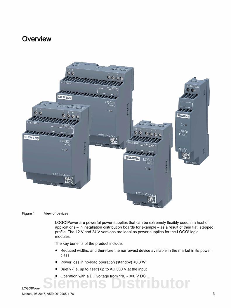
Figure 1 View of devices
LOGO!Power are powerful power supplies that can be extremely flexibly used in a host of applications – in installation distribution boards for example – as a result of their flat, stepped profile. The 12 V and 24 V versions are ideal as power supplies for the LOGO! logic modules.
The key benefits of the product include:
● Reduced widths, and therefore the narrowest device available in the market in its power class
● Power loss in no-load operation (standby) <0.3 W
● Briefly (i.e. up to 1sec) up to AC 300 V at the input
● Operation with a DC voltage from 110 - 300 V DC
Siemens Distributor
Overview
LOGO!Power 4 Manual, 06.2017, A5E40912965-1-76
● Improved efficiency across the entire load range
● Power reserve of 150 % (typ. 200 ms) for capacitive loads when the power supply runs up
● Measuring point for actual output current
● Extended operating temperature range from -25 °C up to +70 °C (derating from 55 °C)
● Standard rail and wall mounting
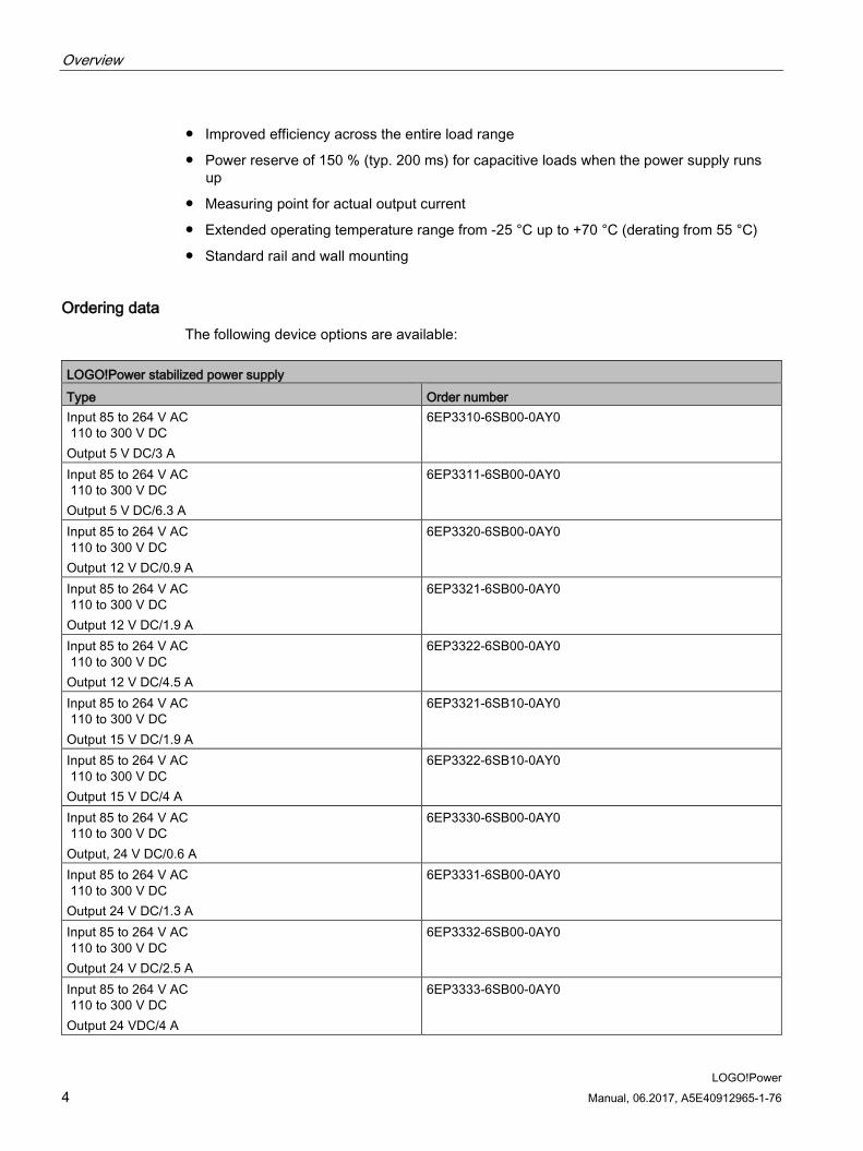
Ordering data The following device options are available:
LOGO!Power stabilized power supply Type Order number Input 85 to 264 V AC 110 to 300 V DC Output 5 V DC/3 A
6EP3310-6SB00-0AY0
Input 85 to 264 V AC 110 to 300 V DC Output 5 V DC/6.3 A
6EP3311-6SB00-0AY0
Input 85 to 264 V AC 110 to 300 V DC Output 12 V DC/0.9 A
6EP3320-6SB00-0AY0
Input 85 to 264 V AC 110 to 300 V DC Output 12 V DC/1.9 A
6EP3321-6SB00-0AY0
Input 85 to 264 V AC 110 to 300 V DC Output 12 V DC/4.5 A
6EP3322-6SB00-0AY0
Input 85 to 264 V AC 110 to 300 V DC Output 15 V DC/1.9 A
6EP3321-6SB10-0AY0
Input 85 to 264 V AC 110 to 300 V DC Output 15 V DC/4 A
6EP3322-6SB10-0AY0
Input 85 to 264 V AC 110 to 300 V DC Output, 24 V DC/0.6 A
6EP3330-6SB00-0AY0
Input 85 to 264 V AC 110 to 300 V DC Output 24 V DC/1.3 A
6EP3331-6SB00-0AY0
Input 85 to 264 V AC 110 to 300 V DC Output 24 V DC/2.5 A
6EP3332-6SB00-0AY0
Input 85 to 264 V AC 110 to 300 V DC Output 24 VDC/4 A
6EP3333-6SB00-0AY0
LOGO!Power Manual, 06.2017, A5E40912965-1-76 5
Table of contents
Overview................................................................................................................................................. 3
1 Safety instructions ................................................................................................................................... 7
2 Description, device design, dimension drawing........................................................................................ 9
2.1 Device description ..................................................................................................................... 9
2.2 Connections and terminal designation.................................................................................... 11
2.3 Potentiometer .......................................................................................................................... 13
2.4 Status displays and signaling ................................................................................................. 14
2.5 Block diagram ......................................................................................................................... 16
2.6 Dimensions and weight ........................................................................................................... 17
3 Mounting/removal ................................................................................................................................. 21
4 Mounting position, mounting clearances ................................................................................................ 23
4.1 Standard mounting position .................................................................................................... 23
4.2 Other mounting positions ........................................................................................................ 28 4.2.1 6EP3310-6SB00-0AY0 (5V 3A) .............................................................................................. 28 4.2.2 6EP3311-6SB00-0AY0 (5V 6.3A) ........................................................................................... 30 4.2.3 6EP3320-6SB00-0AY0 (12V 0.9A) ......................................................................................... 32 4.2.4 6EP3321-6SB00-0AY0 (12V 1.9A) ......................................................................................... 34 4.2.5 6EP3322-6SB00-0AY0 (12V 4.5A) ......................................................................................... 36 4.2.6 6EP3321-6SB10-0AY0 (15V 1.9A) ......................................................................................... 38 4.2.7 6EP3322-6SB10-0AY0 (15V 4A) ............................................................................................ 40 4.2.8 6EP3330-6SB00-0AY0 (24V 0.6A) ......................................................................................... 42 4.2.9 6EP3331-6SB00-0AY0 (24V 1.3A) ......................................................................................... 44 4.2.10 6EP3332-6SB10-0AY0 (24V 2.5A) ......................................................................................... 46 4.2.11 6EP3333-6SB00-0AY0 (24V 4A) ............................................................................................ 48
5 Installation ............................................................................................................................................ 51
5.1 Line-side connection ............................................................................................................... 51
5.2 Output-side connection ........................................................................................................... 53
6 Technical data ...................................................................................................................................... 55
6.1 Input ........................................................................................................................................ 55
6.2 Output ..................................................................................................................................... 58
6.3 Efficiency and power loss ....................................................................................................... 63
6.4 Closed-loop control ................................................................................................................. 69
6.5 Protection and monitoring ....................................................................................................... 70
6.6 MTBF ...................................................................................................................................... 71
6.7 Mechanical system ................................................................................................................. 72
Siemens Distributor
Table of contents
LOGO!Power 6 Manual, 06.2017, A5E40912965-1-76
6.8 Dimension drawing ................................................................................................................ 73
7 Safety, approvals, EMC ........................................................................................................................ 75
7.1 Safety ..................................................................................................................................... 75
7.2 Test voltage ............................................................................................................................ 76
7.3 Certifications .......................................................................................................................... 77
7.4 EMC ....................................................................................................................................... 78
8 Ambient conditions ................................................................................................................................ 79
9 Applications .......................................................................................................................................... 81
9.1 Parallel connection to increase power rating ......................................................................... 81
9.2 Parallel connection for redundancy ....................................................................................... 83
9.3 Series connection for increased voltage ................................................................................ 84
9.4 Protection against short-time voltage dips ............................................................................. 85
10 Environment ......................................................................................................................................... 87
11 Service & Support ................................................................................................................................. 89
LOGO!Power Manual, 06.2017, A5E40912965-1-76 7
Safety instructions 1
WARNING
Correct handling of the devices
When operating electrical devices, it is inevitable that certain components will carry dangerous voltages.
Therefore, failure to handle the units properly can result in death or serious physical injury as well as extensive property damage.
Only appropriately qualified personnel may work on or in the vicinity of this equipment.
Perfect, safe, and reliable operation of this equipment is dependent on proper transportation, storage, installation and mounting.
Before installation or maintenance work can begin, the system's main switch must be switched off and measures taken to prevent it being switched on again.
If this instruction is not observed, touching live parts can result in death or serious injury.
Siemens Distributor
Safety instructions
LOGO!Power 8 Manual, 06.2017, A5E40912965-1-76
LOGO!Power Manual, 06.2017, A5E40912965-1-76 9
Description, device design, dimension drawing 2 2.1 Device description
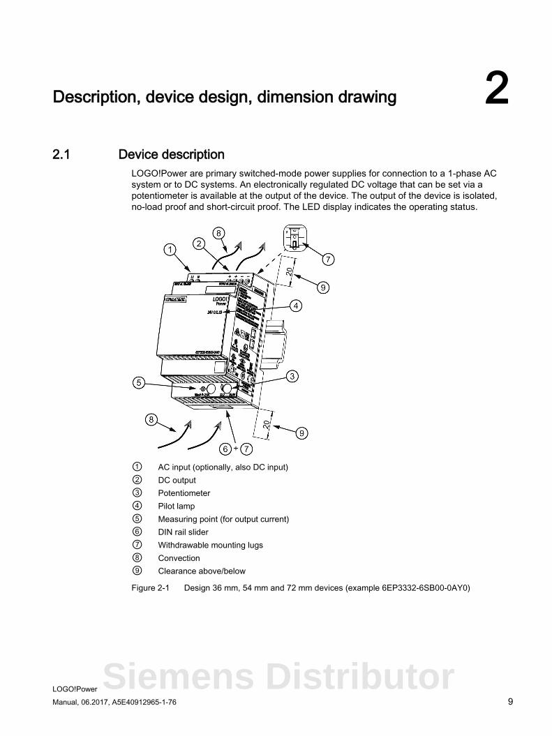
LOGO!Power are primary switched-mode power supplies for connection to a 1-phase AC system or to DC systems. An electronically regulated DC voltage that can be set via a potentiometer is available at the output of the device. The output of the device is isolated, no-load proof and short-circuit proof. The LED display indicates the operating status.
① AC input (optionally, also DC input) ② DC output ③ Potentiometer ④ Pilot lamp ⑤ Measuring point (for output current) ⑥ DIN rail slider ⑦ Withdrawable mounting lugs ⑧ Convection ⑨ Clearance above/below
Figure 2-1 Design 36 mm, 54 mm and 72 mm devices (example 6EP3332-6SB00-0AY0)
Siemens Distributor
Description, device design, dimension drawing 2.1 Device description
LOGO!Power 10 Manual, 06.2017, A5E40912965-1-76
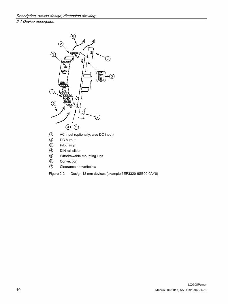
① AC input (optionally, also DC input) ② DC output ③ Pilot lamp ④ DIN rail slider ⑤ Withdrawable mounting lugs ⑥ Convection ⑦ Clearance above/below
Figure 2-2 Design 18 mm devices (example 6EP3320-6SB00-0AY0)
Description, device design, dimension drawing 2.2 Connections and terminal designation
LOGO!Power Manual, 06.2017, A5E40912965-1-76 11
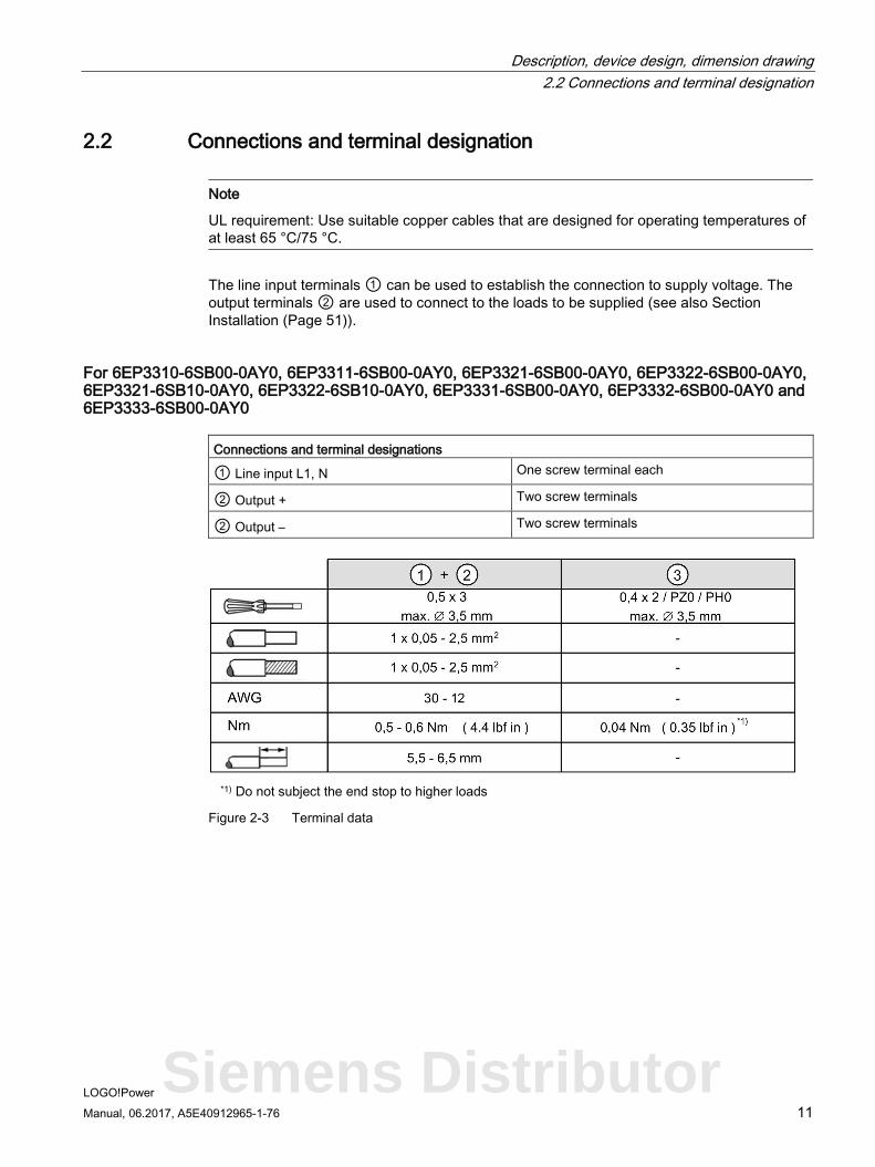
2.2 Connections and terminal designation
Note
UL requirement: Use suitable copper cables that are designed for operating temperatures of at least 65 °C/75 °C.
The line input terminals ① can be used to establish the connection to supply voltage. The output terminals ② are used to connect to the loads to be supplied (see also Section Installation (Page 51)).
For 6EP3310-6SB00-0AY0, 6EP3311-6SB00-0AY0, 6EP3321-6SB00-0AY0, 6EP3322-6SB00-0AY0, 6EP3321-6SB10-0AY0, 6EP3322-6SB10-0AY0, 6EP3331-6SB00-0AY0, 6EP3332-6SB00-0AY0 and 6EP3333-6SB00-0AY0
Connections and terminal designations
① Line input L1, N One screw terminal each
② Output + Two screw terminals
② Output – Two screw terminals
*1) Do not subject the end stop to higher loads
Figure 2-3 Terminal data
Siemens Distributor
Description, device design, dimension drawing 2.2 Connections and terminal designation
LOGO!Power 12 Manual, 06.2017, A5E40912965-1-76
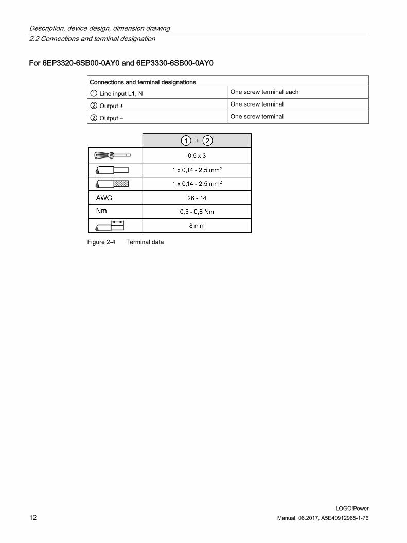
For 6EP3320-6SB00-0AY0 and 6EP3330-6SB00-0AY0 Connections and terminal designations
① Line input L1, N One screw terminal each
② Output + One screw terminal
② Output – One screw terminal
Figure 2-4 Terminal data
Description, device design, dimension drawing 2.3 Potentiometer
LOGO!Power Manual, 06.2017, A5E40912965-1-76 13
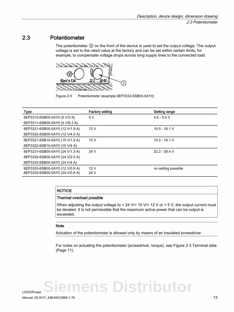
2.3 Potentiometer The potentiometer ③ on the front of the device is used to set the output voltage. The output voltage is set to the rated value at the factory and can be set within certain limits; for example, to compensate voltage drops across long supply lines to the connected load.
Figure 2-5 Potentiometer (example 6EP3332-6SB00-0AY0)
Type Factory setting Setting range 6EP3310-6SB00-0AY0 (5 V/3 A) 6EP3311-6SB00-0AY0 (5 V/6.3 A)
5 V 4.6 - 5.4 V
6EP3321-6SB00-0AY0 (12 V/1.9 A) 6EP3322-6SB00-0AY0 (12 V/4.5 A)
12 V 10.5 - 16.1 V
6EP3321-6SB10-0AY0 (15 V/1.9 A) 6EP3322-6SB10-0AY0 (15 V/4 A)
15 V 10.5 - 16.1 V
6EP3331-6SB00-0AY0 (24 V/1.3 A) 6EP3332-6SB00-0AY0 (24 V/2.5 A) 6EP3333-6SB00-0AY0 (24 V/4 A)
24 V 22.2 - 26.4 V
6EP3320-6SB00-0AY0 (12 V/0.9 A) 6EP3330-6SB00-0AY0 (24 V/0.6 A)
12 V 24 V
no setting possible
NOTICE
Thermal overload possible
When adjusting the output voltage to > 24 V/> 15 V/> 12 V or > 5 V, the output current must be derated. It is not permissible that the maximum active power that can be output is exceeded.
Note
Actuation of the potentiometer is allowed only by means of an insulated screwdriver.
For notes on actuating the potentiometer (screwdriver, torque), see Figure 2-3 Terminal data (Page 11).
Siemens Distributor
Description, device design, dimension drawing 2.4 Status displays and signaling
LOGO!Power 14 Manual, 06.2017, A5E40912965-1-76
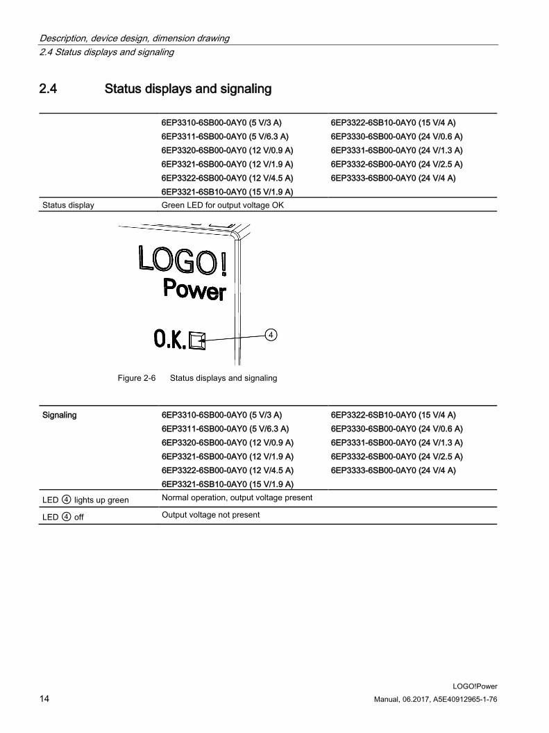
2.4 Status displays and signaling
6EP3310-6SB00-0AY0 (5 V/3 A) 6EP3311-6SB00-0AY0 (5 V/6.3 A) 6EP3320-6SB00-0AY0 (12 V/0.9 A) 6EP3321-6SB00-0AY0 (12 V/1.9 A) 6EP3322-6SB00-0AY0 (12 V/4.5 A) 6EP3321-6SB10-0AY0 (15 V/1.9 A)
6EP3322-6SB10-0AY0 (15 V/4 A) 6EP3330-6SB00-0AY0 (24 V/0.6 A) 6EP3331-6SB00-0AY0 (24 V/1.3 A) 6EP3332-6SB00-0AY0 (24 V/2.5 A) 6EP3333-6SB00-0AY0 (24 V/4 A)
Status display Green LED for output voltage OK
Figure 2-6 Status displays and signaling
Signaling 6EP3310-6SB00-0AY0 (5 V/3 A) 6EP3311-6SB00-0AY0 (5 V/6.3 A) 6EP3320-6SB00-0AY0 (12 V/0.9 A) 6EP3321-6SB00-0AY0 (12 V/1.9 A) 6EP3322-6SB00-0AY0 (12 V/4.5 A) 6EP3321-6SB10-0AY0 (15 V/1.9 A)
6EP3322-6SB10-0AY0 (15 V/4 A) 6EP3330-6SB00-0AY0 (24 V/0.6 A) 6EP3331-6SB00-0AY0 (24 V/1.3 A) 6EP3332-6SB00-0AY0 (24 V/2.5 A) 6EP3333-6SB00-0AY0 (24 V/4 A)
LED ④ lights up green Normal operation, output voltage present
LED ④ off Output voltage not present
Description, device design, dimension drawing 2.4 Status displays and signaling
LOGO!Power Manual, 06.2017, A5E40912965-1-76 15
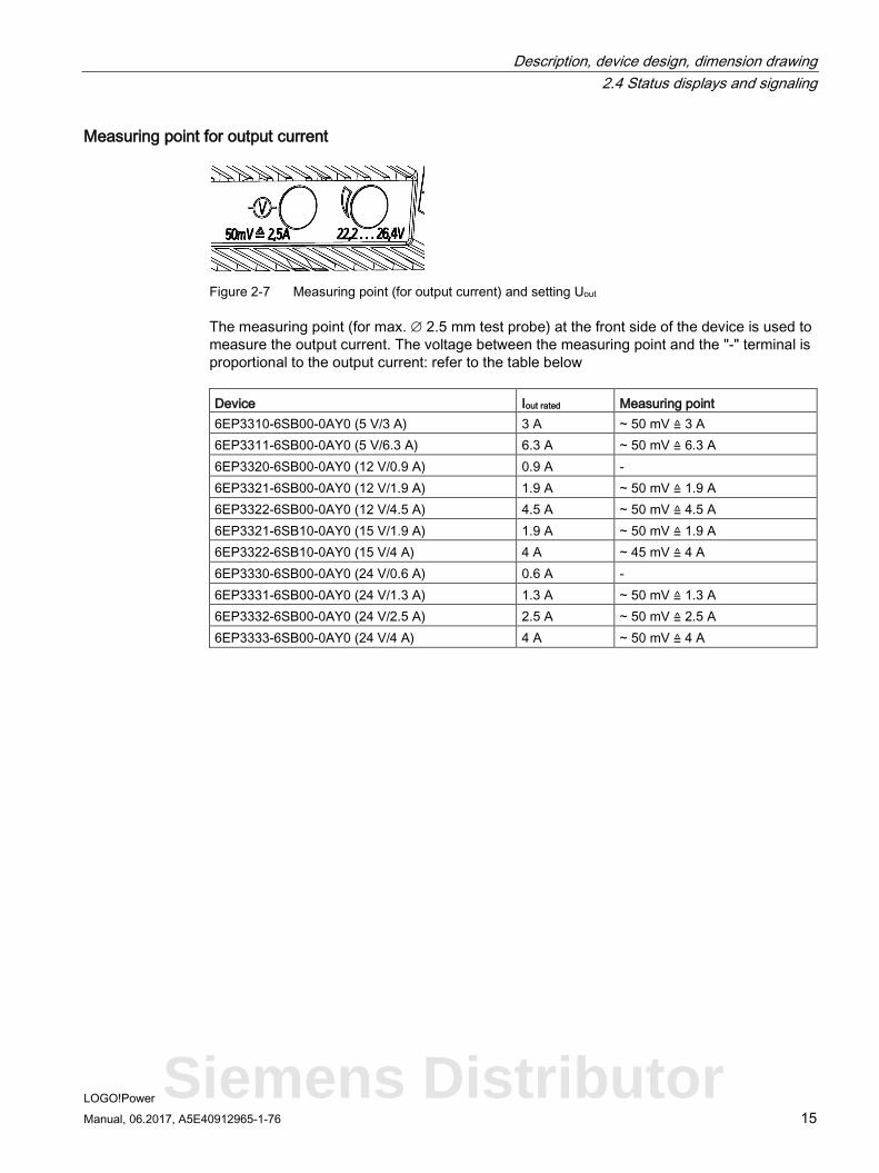
Measuring point for output current
Figure 2-7 Measuring point (for output current) and setting Uout
The measuring point (for max. ∅ 2.5 mm test probe) at the front side of the device is used to measure the output current. The voltage between the measuring point and the "-" terminal is proportional to the output current: refer to the table below Device Iout rated Measuring point 6EP3310-6SB00-0AY0 (5 V/3 A) 3 A ~ 50 mV ≙ 3 A 6EP3311-6SB00-0AY0 (5 V/6.3 A) 6.3 A ~ 50 mV ≙ 6.3 A 6EP3320-6SB00-0AY0 (12 V/0.9 A) 0.9 A - 6EP3321-6SB00-0AY0 (12 V/1.9 A) 1.9 A ~ 50 mV ≙ 1.9 A 6EP3322-6SB00-0AY0 (12 V/4.5 A) 4.5 A ~ 50 mV ≙ 4.5 A 6EP3321-6SB10-0AY0 (15 V/1.9 A) 1.9 A ~ 50 mV ≙ 1.9 A 6EP3322-6SB10-0AY0 (15 V/4 A) 4 A ~ 45 mV ≙ 4 A 6EP3330-6SB00-0AY0 (24 V/0.6 A) 0.6 A - 6EP3331-6SB00-0AY0 (24 V/1.3 A) 1.3 A ~ 50 mV ≙ 1.3 A 6EP3332-6SB00-0AY0 (24 V/2.5 A) 2.5 A ~ 50 mV ≙ 2.5 A 6EP3333-6SB00-0AY0 (24 V/4 A) 4 A ~ 50 mV ≙ 4 A
Siemens Distributor
Description, device design, dimension drawing 2.5 Block diagram
LOGO!Power 16 Manual, 06.2017, A5E40912965-1-76
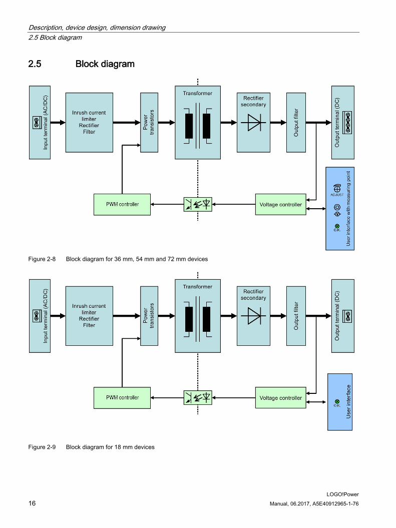
2.5 Block diagram
Figure 2-8 Block diagram for 36 mm, 54 mm and 72 mm devices
Figure 2-9 Block diagram for 18 mm devices
Description, device design, dimension drawing 2.6 Dimensions and weight
LOGO!Power Manual, 06.2017, A5E40912965-1-76 17
2.6 Dimensions and weight
Figure 2-10 Dimension drawing for 6EP3320-6SB00-0AY0 and 6EP3330-6SB00-0AY0
Siemens Distributor
Description, device design, dimension drawing 2.6 Dimensions and weight
LOGO!Power 18 Manual, 06.2017, A5E40912965-1-76
Figure 2-11 Dimension drawing for 6EP3310-6SB00-0AY0, 6EP3321-6SB00-0AY0, 6EP3321-
6SB10-0AY0 and EP3331-6SB00-0AY0
Description, device design, dimension drawing 2.6 Dimensions and weight
LOGO!Power Manual, 06.2017, A5E40912965-1-76 19
Figure 2-12 Dimension drawing for 6EP3311-6SB00-0AY0, 6EP3322-6SB00-0AY0, 6EP3322-
6SB10-0AY0 and 6EP3332-6SB00-0AY0
Figure 2-13 Dimension drawing for 6EP3333-6SB00-0AY0
Siemens Distributor
Description, device design, dimension drawing 2.6 Dimensions and weight
LOGO!Power 20 Manual, 06.2017, A5E40912965-1-76
6EP3320-6SB00-0AY0 (12 V/0.9 A) 6EP3330-6SB00-0AY0 (24 V/0.6 A)
6EP3310-6SB00-0AY0 (5 V/3 A) 6EP3321-6SB00-0AY0 (12 V/1.9 A) 6EP3321-6SB10-0AY0 (15 V/1.9 A) 6EP3331-6SB00-0AY0 (24 V/1.3 A)
6EP3311-6SB00-0AY0 (5 V/6.3 A) 6EP3322-6SB00-0AY0 (12 V/4.5 A) 6EP3322-6SB10-0AY0 (15 V/4 A) 6EP3332-6SB00-0AY0 (24 V/2.5 A)
6EP3333-6SB00-0AY0 (24 V/4 A)
Dimensions (W × H × D) in mm
18 × 90 × 53 36 × 90 × 53 54 × 90 × 53 72 × 90 × 53
Weight 0.07 kg 0.12 kg 0.2 kg 0.29 kg
LOGO!Power Manual, 06.2017, A5E40912965-1-76 21
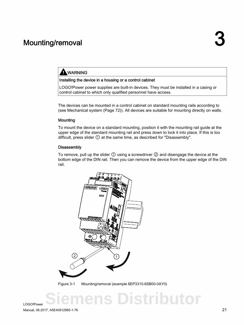
Mounting/removal 3
WARNING
Installing the device in a housing or a control cabinet
LOGO!Power power supplies are built-in devices. They must be installed in a casing or control cabinet to which only qualified personnel have access.
The devices can be mounted in a control cabinet on standard mounting rails according to (see Mechanical system (Page 72)). All devices are suitable for mounting directly on walls.
Mounting
To mount the device on a standard mounting, position it with the mounting rail guide at the upper edge of the standard mounting rail and press down to lock it into place. If this is too difficult, press slider ① at the same time, as described for "Disassembly".
Disassembly
To remove, pull up the slider ① using a screwdriver ② and disengage the device at the bottom edge of the DIN rail. Then you can remove the device from the upper edge of the DIN rail.
Figure 3-1 Mounting/removal (example 6EP3310-6SB00-0AY0)
Siemens Distributor
Mounting/removal
LOGO!Power 22 Manual, 06.2017, A5E40912965-1-76
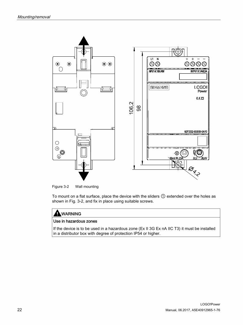
Figure 3-2 Wall mounting
To mount on a flat surface, place the device with the sliders ① extended over the holes as shown in Fig. 3-2, and fix in place using suitable screws.
WARNING
Use in hazardous zones
If the device is to be used in a hazardous zone (Ex II 3G Ex nA IIC T3) it must be installed in a distributor box with degree of protection IP54 or higher.
LOGO!Power Manual, 06.2017, A5E40912965-1-76 23
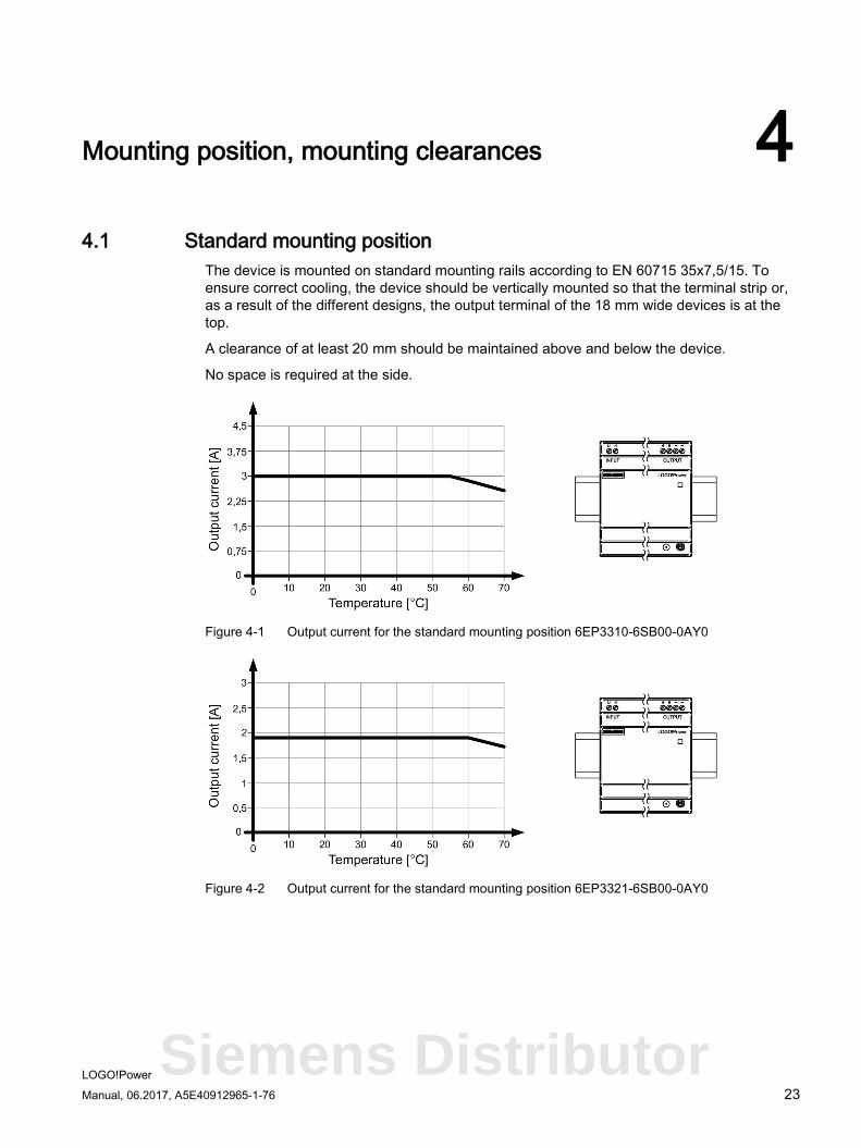
Mounting position, mounting clearances 4 4.1 Standard mounting position
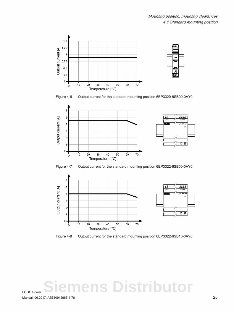
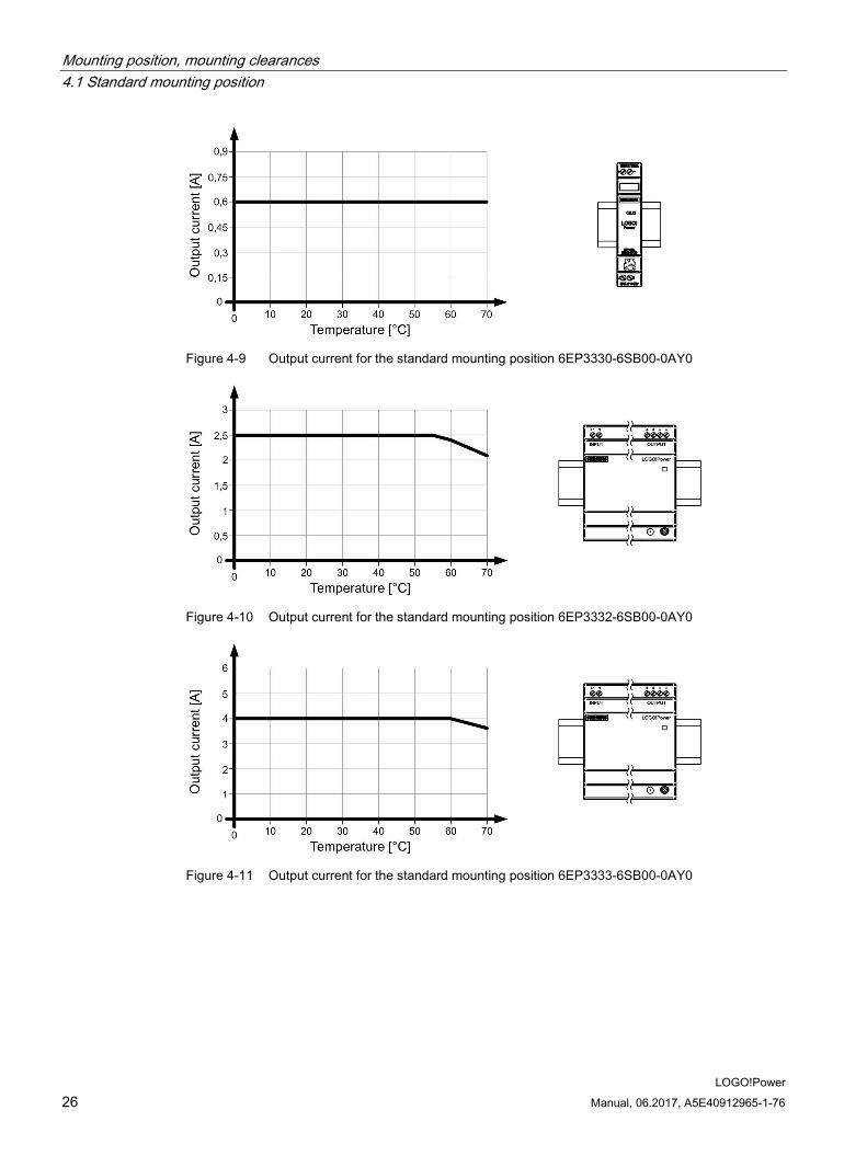
The device is mounted on standard mounting rails according to EN 60715 35x7,5/15. To ensure correct cooling, the device should be vertically mounted so that the terminal strip or, as a result of the different designs, the output terminal of the 18 mm wide devices is at the top.
A clearance of at least 20 mm should be maintained above and below the device.
No space is required at the side.
Figure 4-1 Output current for the standard mounting position 6EP3310-6SB00-0AY0
Figure 4-2 Output current for the standard mounting position 6EP3321-6SB00-0AY0
Siemens Distributor
Mounting position, mounting clearances 4.1 Standard mounting position
LOGO!Power 24 Manual, 06.2017, A5E40912965-1-76
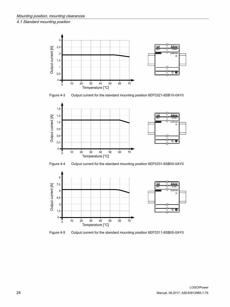
Figure 4-3 Output current for the standard mounting position 6EP3321-6SB10-0AY0
Figure 4-4 Output current for the standard mounting position 6EP3331-6SB00-0AY0
Figure 4-5 Output current for the standard mounting position 6EP3311-6SB00-0AY0
Mounting position, mounting clearances 4.1 Standard mounting position
LOGO!Power Manual, 06.2017, A5E40912965-1-76 25
Figure 4-6 Output current for the standard mounting position 6EP3320-6SB00-0AY0
Figure 4-7 Output current for the standard mounting position 6EP3322-6SB00-0AY0
Figure 4-8 Output current for the standard mounting position 6EP3322-6SB10-0AY0
Siemens Distributor
Mounting position, mounting clearances 4.1 Standard mounting position
LOGO!Power 26 Manual, 06.2017, A5E40912965-1-76
Figure 4-9 Output current for the standard mounting position 6EP3330-6SB00-0AY0
Figure 4-10 Output current for the standard mounting position 6EP3332-6SB00-0AY0
Figure 4-11 Output current for the standard mounting position 6EP3333-6SB00-0AY0
Mounting position, mounting clearances 4.1 Standard mounting position
LOGO!Power Manual, 06.2017, A5E40912965-1-76 27
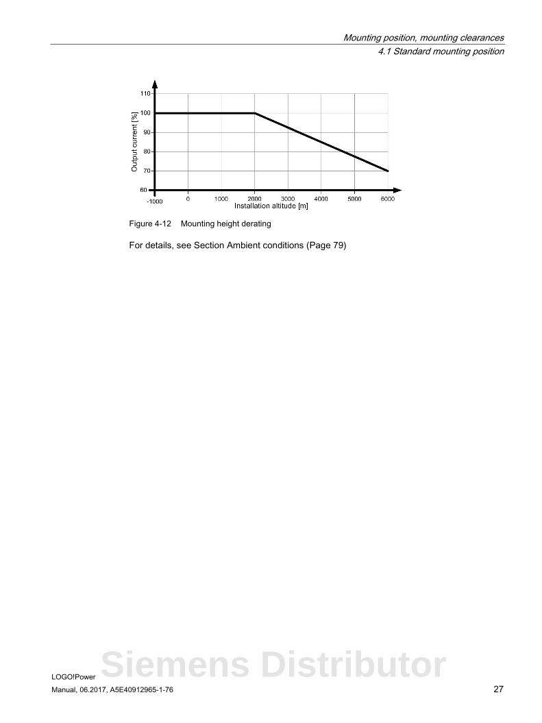
Figure 4-12 Mounting height derating
For details, see Section Ambient conditions (Page 79)
Siemens Distributor
Mounting position, mounting clearances 4.2 Other mounting positions
LOGO!Power 28 Manual, 06.2017, A5E40912965-1-76
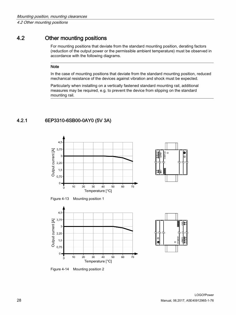
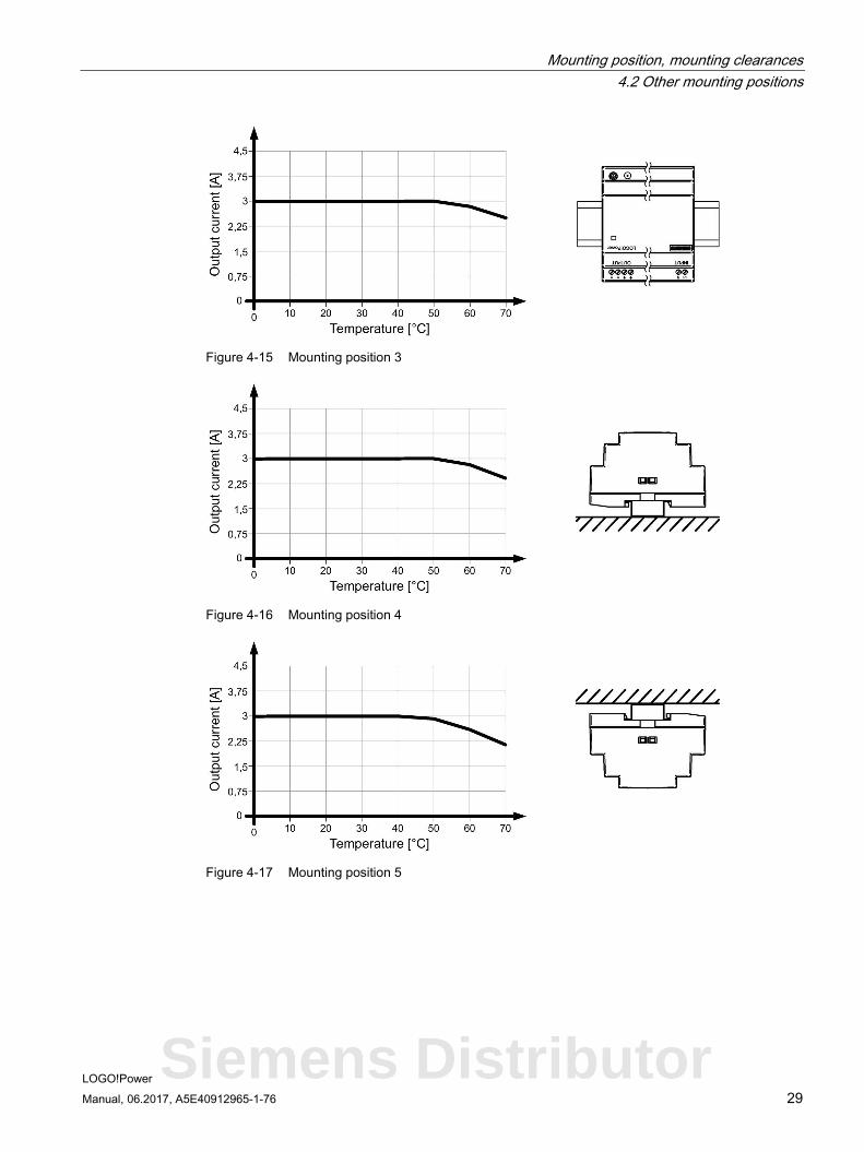
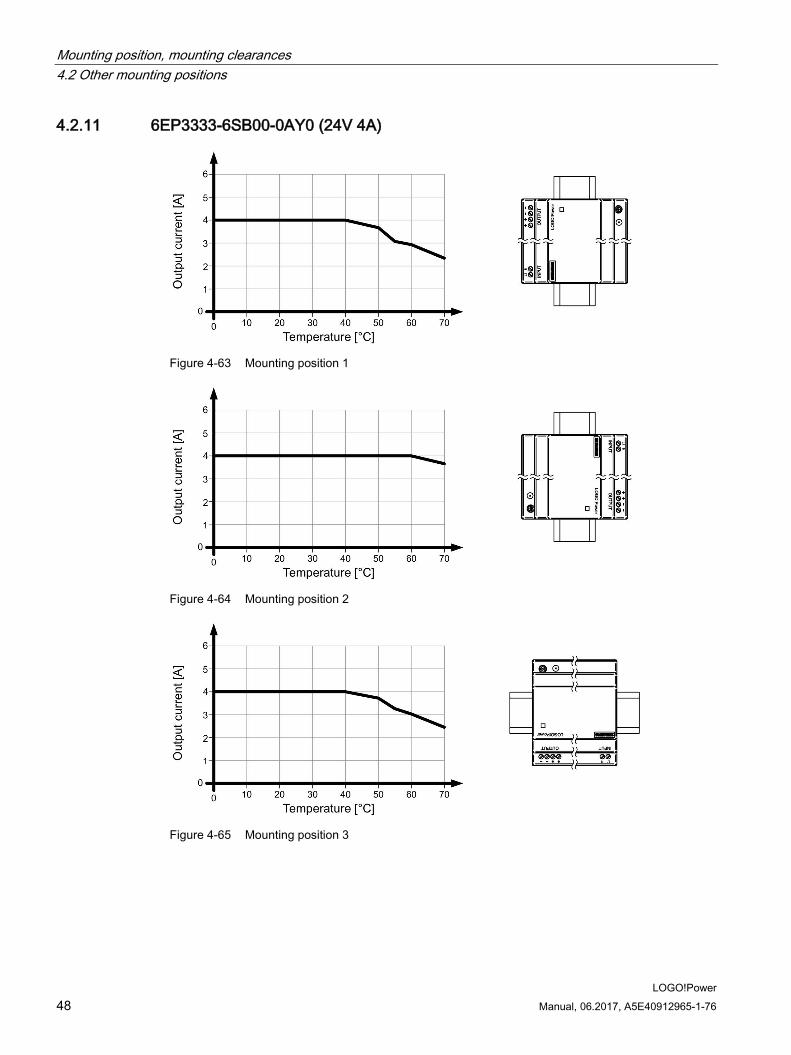
4.2 Other mounting positions For mounting positions that deviate from the standard mounting position, derating factors (reduction of the output power or the permissible ambient temperature) must be observed in accordance with the following diagrams.
Note
In the case of mounting positions that deviate from the standard mounting position, reduced mechanical resistance of the devices against vibration and shock must be expected.
Particularly when installing on a vertically fastened standard mounting rail, additional measures may be required, e.g. to prevent the device from slipping on the standard mounting rail.
4.2.1 6EP3310-6SB00-0AY0 (5V 3A)
Figure 4-13 Mounting position 1
Figure 4-14 Mounting position 2
Mounting position, mounting clearances 4.2 Other mounting positions
LOGO!Power Manual, 06.2017, A5E40912965-1-76 29
Figure 4-15 Mounting position 3
Figure 4-16 Mounting position 4
Figure 4-17 Mounting position 5
Siemens Distributor

Mounting position, mounting clearances 4.2 Other mounting positions
LOGO!Power 30 Manual, 06.2017, A5E40912965-1-76
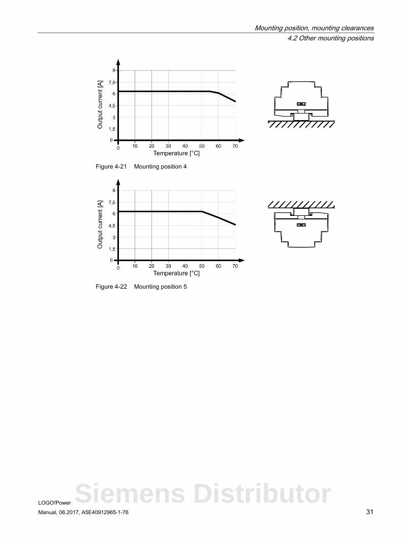
4.2.2 6EP3311-6SB00-0AY0 (5V 6.3A)
Figure 4-18 Mounting position 1
Figure 4-19 Mounting position 2
Figure 4-20 Mounting position 3
Mounting position, mounting clearances 4.2 Other mounting positions
LOGO!Power Manual, 06.2017, A5E40912965-1-76 31
Figure 4-21 Mounting position 4
Figure 4-22 Mounting position 5
Siemens Distributor
Mounting position, mounting clearances 4.2 Other mounting positions
LOGO!Power 32 Manual, 06.2017, A5E40912965-1-76
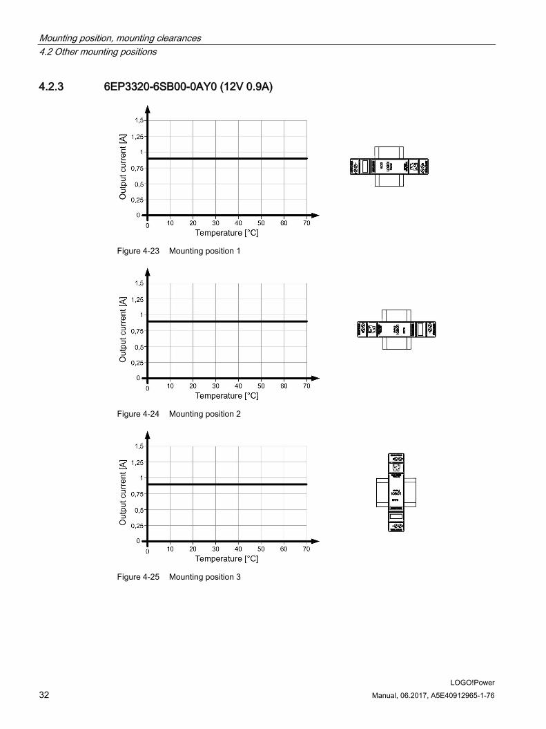
4.2.3 6EP3320-6SB00-0AY0 (12V 0.9A)
Figure 4-23 Mounting position 1
Figure 4-24 Mounting position 2
Figure 4-25 Mounting position 3
Mounting position, mounting clearances 4.2 Other mounting positions
LOGO!Power Manual, 06.2017, A5E40912965-1-76 33
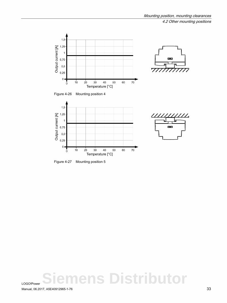
Figure 4-26 Mounting position 4
Figure 4-27 Mounting position 5
Siemens Distributor
Mounting position, mounting clearances 4.2 Other mounting positions
LOGO!Power 34 Manual, 06.2017, A5E40912965-1-76
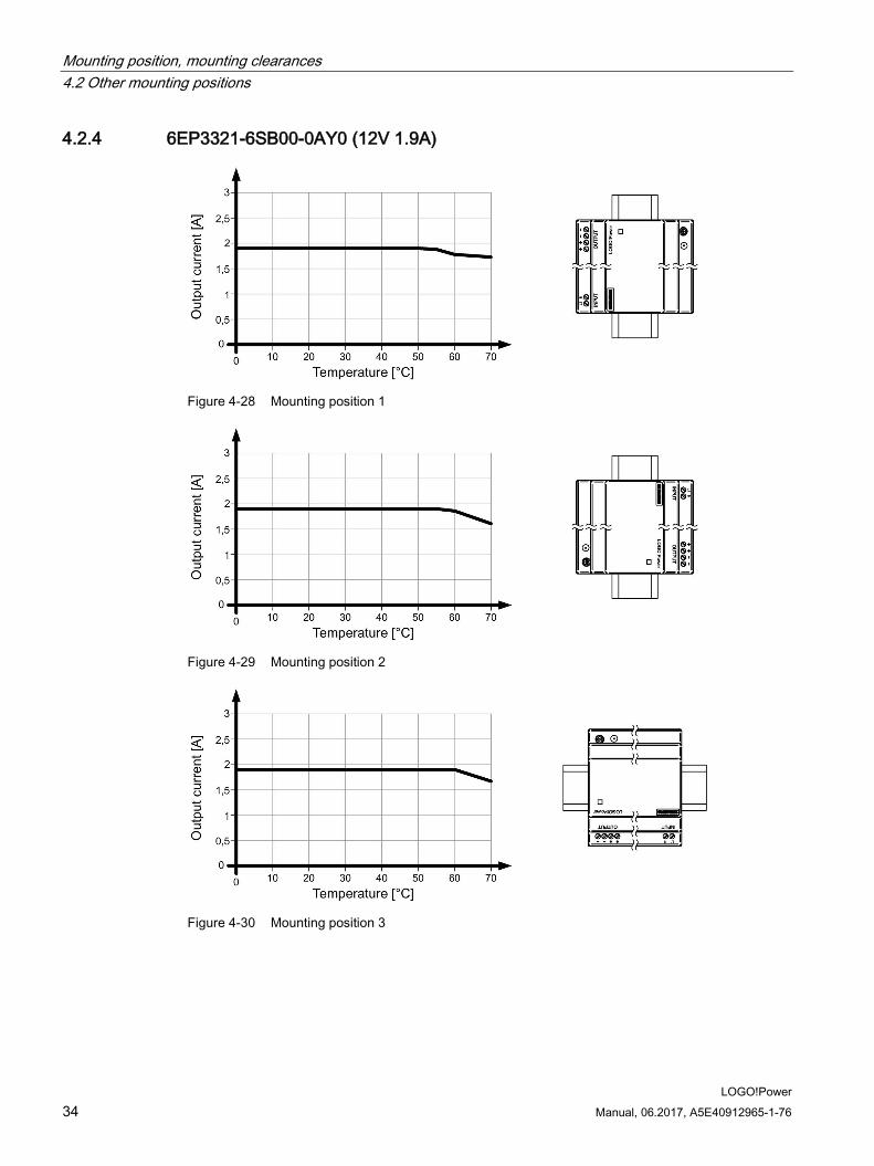
4.2.4 6EP3321-6SB00-0AY0 (12V 1.9A)
Figure 4-28 Mounting position 1
Figure 4-29 Mounting position 2
Figure 4-30 Mounting position 3

Mounting position, mounting clearances 4.2 Other mounting positions
LOGO!Power Manual, 06.2017, A5E40912965-1-76 35
Figure 4-31 Mounting position 4
Figure 4-32 Mounting position 5
Siemens Distributor

Mounting position, mounting clearances 4.2 Other mounting positions
LOGO!Power 36 Manual, 06.2017, A5E40912965-1-76
4.2.5 6EP3322-6SB00-0AY0 (12V 4.5A)
Figure 4-33 Mounting position 1
Figure 4-34 Mounting position 2
Figure 4-35 Mounting position 3

Mounting position, mounting clearances 4.2 Other mounting positions
LOGO!Power Manual, 06.2017, A5E40912965-1-76 37
Figure 4-36 Mounting position 4
Figure 4-37 Mounting position 5
Siemens Distributor

Mounting position, mounting clearances 4.2 Other mounting positions
LOGO!Power 38 Manual, 06.2017, A5E40912965-1-76
4.2.6 6EP3321-6SB10-0AY0 (15V 1.9A)
Figure 4-38 Mounting position 1
Figure 4-39 Mounting position 2
Figure 4-40 Mounting position 3

Mounting position, mounting clearances 4.2 Other mounting positions
LOGO!Power Manual, 06.2017, A5E40912965-1-76 39
Figure 4-41 Mounting position 4
Figure 4-42 Mounting position 5
Siemens Distributor

Mounting position, mounting clearances 4.2 Other mounting positions
LOGO!Power 40 Manual, 06.2017, A5E40912965-1-76
4.2.7 6EP3322-6SB10-0AY0 (15V 4A)
Figure 4-43 Mounting position 1
Figure 4-44 Mounting position 2
Figure 4-45 Mounting position 3

Mounting position, mounting clearances 4.2 Other mounting positions
LOGO!Power Manual, 06.2017, A5E40912965-1-76 41
Figure 4-46 Mounting position 4
Figure 4-47 Mounting position 5
Siemens Distributor
Mounting position, mounting clearances 4.2 Other mounting positions
LOGO!Power 42 Manual, 06.2017, A5E40912965-1-76
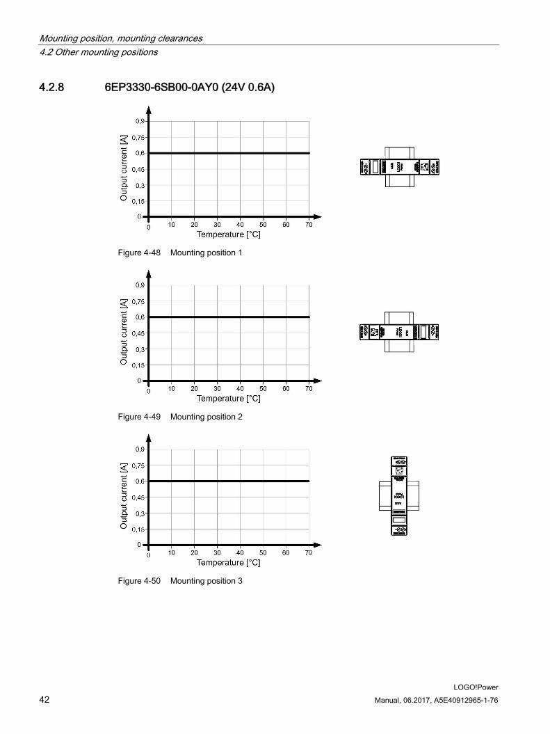
4.2.8 6EP3330-6SB00-0AY0 (24V 0.6A)
Figure 4-48 Mounting position 1
Figure 4-49 Mounting position 2
Figure 4-50 Mounting position 3
Mounting position, mounting clearances 4.2 Other mounting positions
LOGO!Power Manual, 06.2017, A5E40912965-1-76 43
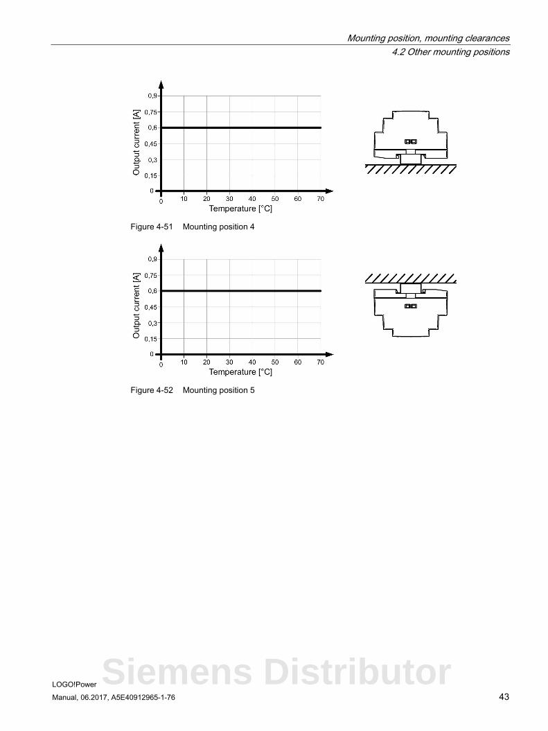
Figure 4-51 Mounting position 4
Figure 4-52 Mounting position 5
Siemens Distributor

Mounting position, mounting clearances 4.2 Other mounting positions
LOGO!Power 44 Manual, 06.2017, A5E40912965-1-76
4.2.9 6EP3331-6SB00-0AY0 (24V 1.3A)
Figure 4-53 Mounting position 1
Figure 4-54 Mounting position 2
Figure 4-55 Mounting position 3

Mounting position, mounting clearances 4.2 Other mounting positions
LOGO!Power Manual, 06.2017, A5E40912965-1-76 45
Figure 4-56 Mounting position 4
Figure 4-57 Mounting position 5
Siemens Distributor
Mounting position, mounting clearances 4.2 Other mounting positions
LOGO!Power 46 Manual, 06.2017, A5E40912965-1-76
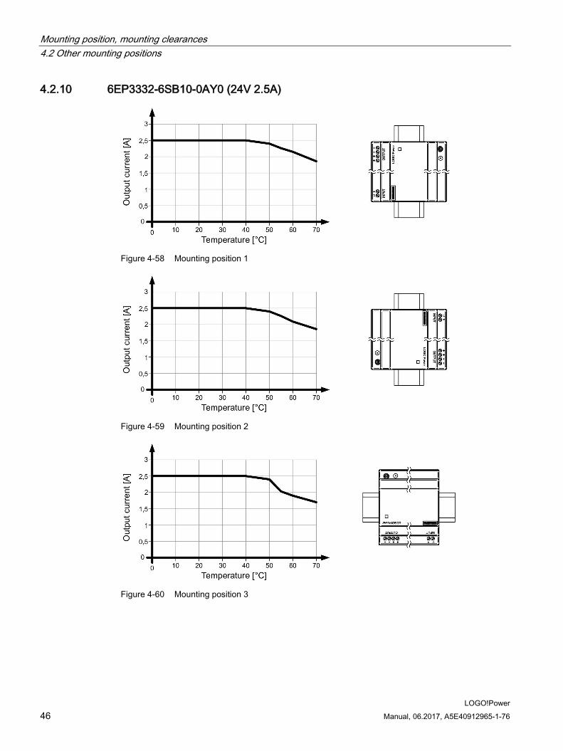
4.2.10 6EP3332-6SB10-0AY0 (24V 2.5A)
Figure 4-58 Mounting position 1
Figure 4-59 Mounting position 2
Figure 4-60 Mounting position 3

Mounting position, mounting clearances 4.2 Other mounting positions
LOGO!Power Manual, 06.2017, A5E40912965-1-76 47
Figure 4-61 Mounting position 4
Figure 4-62 Mounting position 5
Siemens Distributor
Mounting position, mounting clearances 4.2 Other mounting positions
LOGO!Power 48 Manual, 06.2017, A5E40912965-1-76
4.2.11 6EP3333-6SB00-0AY0 (24V 4A)
Figure 4-63 Mounting position 1
Figure 4-64 Mounting position 2
Figure 4-65 Mounting position 3

Mounting position, mounting clearances 4.2 Other mounting positions
LOGO!Power Manual, 06.2017, A5E40912965-1-76 49
Figure 4-66 Mounting position 4
Figure 4-67 Mounting position 5
Siemens Distributor
Mounting position, mounting clearances 4.2 Other mounting positions
LOGO!Power 50 Manual, 06.2017, A5E40912965-1-76
LOGO!Power Manual, 06.2017, A5E40912965-1-76 51
Installation 5
WARNING
Hazard due to electric shock
Before installation or maintenance work can begin, the system's main switch must be switched off and measures taken to prevent it being switched on again. If this instruction is not observed, touching live parts can result in death or serious injury.
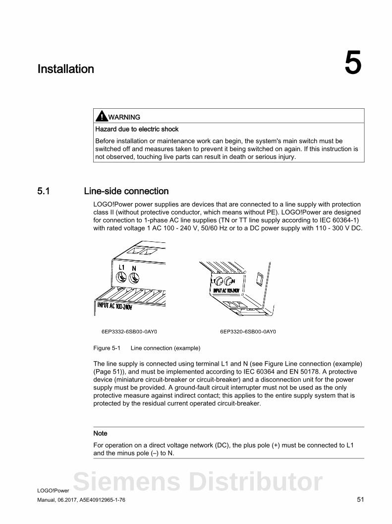
5.1 Line-side connection LOGO!Power power supplies are devices that are connected to a line supply with protection class II (without protective conductor, which means without PE). LOGO!Power are designed for connection to 1-phase AC line supplies (TN or TT line supply according to IEC 60364-1) with rated voltage 1 AC 100 - 240 V, 50/60 Hz or to a DC power supply with 110 - 300 V DC.
Figure 5-1 Line connection (example)
The line supply is connected using terminal L1 and N (see Figure Line connection (example) (Page 51)), and must be implemented according to IEC 60364 and EN 50178. A protective device (miniature circuit-breaker or circuit-breaker) and a disconnection unit for the power supply must be provided. A ground-fault circuit interrupter must not be used as the only protective measure against indirect contact; this applies to the entire supply system that is protected by the residual current operated circuit-breaker.
Note
For operation on a direct voltage network (DC), the plus pole (+) must be connected to L1 and the minus pole (–) to N.
Siemens Distributor
Installation 5.1 Line-side connection
LOGO!Power 52 Manual, 06.2017, A5E40912965-1-76
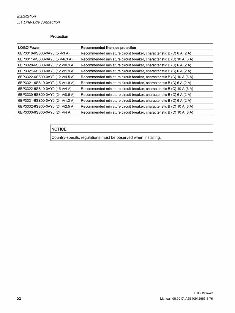
Protection
LOGO!Power Recommended line-side protection 6EP3310-6SB00-0AY0 (5 V/3 A) Recommended miniature circuit breaker, characteristic B (C) 6 A (2 A) 6EP3311-6SB00-0AY0 (5 V/6.3 A) Recommended miniature circuit breaker, characteristic B (C) 10 A (6 A) 6EP3320-6SB00-0AY0 (12 V/0.9 A) Recommended miniature circuit breaker, characteristic B (C) 6 A (2 A) 6EP3321-6SB00-0AY0 (12 V/1.9 A) Recommended miniature circuit breaker, characteristic B (C) 6 A (2 A) 6EP3322-6SB00-0AY0 (12 V/4.5 A) Recommended miniature circuit breaker, characteristic B (C) 10 A (6 A) 6EP3321-6SB10-0AY0 (15 V/1.9 A) Recommended miniature circuit breaker, characteristic B (C) 6 A (2 A) 6EP3322-6SB10-0AY0 (15 V/4 A) Recommended miniature circuit breaker, characteristic B (C) 10 A (6 A) 6EP3330-6SB00-0AY0 (24 V/0.6 A) Recommended miniature circuit breaker, characteristic B (C) 6 A (2 A) 6EP3331-6SB00-0AY0 (24 V/1.3 A) Recommended miniature circuit breaker, characteristic B (C) 6 A (2 A) 6EP3332-6SB00-0AY0 (24 V/2.5 A) Recommended miniature circuit breaker, characteristic B (C) 10 A (6 A) 6EP3333-6SB00-0AY0 (24 V/4 A) Recommended miniature circuit breaker, characteristic B (C) 10 A (6 A)
NOTICE
Country-specific regulations must be observed when installing.
Installation 5.2 Output-side connection
LOGO!Power Manual, 06.2017, A5E40912965-1-76 53
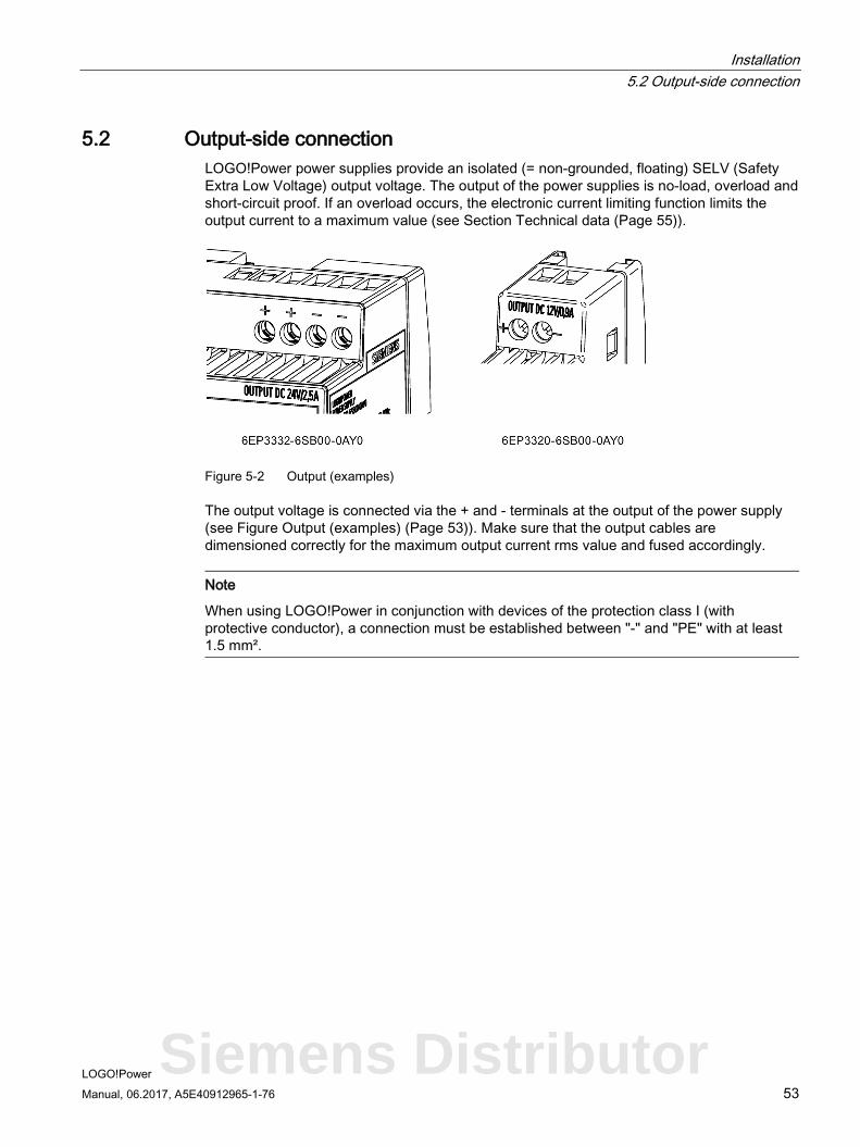
5.2 Output-side connection LOGO!Power power supplies provide an isolated (= non-grounded, floating) SELV (Safety Extra Low Voltage) output voltage. The output of the power supplies is no-load, overload and short-circuit proof. If an overload occurs, the electronic current limiting function limits the output current to a maximum value (see Section Technical data (Page 55)).
Figure 5-2 Output (examples)
The output voltage is connected via the + and - terminals at the output of the power supply (see Figure Output (examples) (Page 53)). Make sure that the output cables are dimensioned correctly for the maximum output current rms value and fused accordingly.
Note
When using LOGO!Power in conjunction with devices of the protection class I (with protective conductor), a connection must be established between "-" and "PE" with at least 1.5 mm².
Siemens Distributor
Installation 5.2 Output-side connection
LOGO!Power 54 Manual, 06.2017, A5E40912965-1-76
LOGO!Power Manual, 06.2017, A5E40912965-1-76 55
Technical data 6
Note
Technical data apply for a rated input voltage, rated load and 25 °C ambient temperature if nothing else is specified.
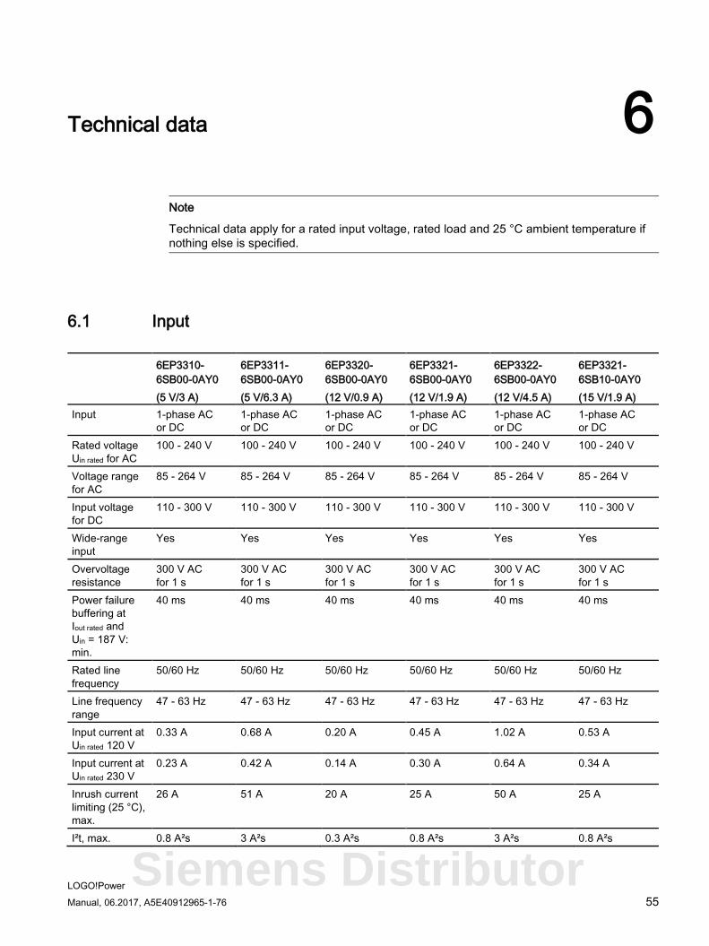
6.1 Input
6EP3310-6SB00-0AY0 (5 V/3 A)
6EP3311-6SB00-0AY0 (5 V/6.3 A)
6EP3320-6SB00-0AY0 (12 V/0.9 A)
6EP3321-6SB00-0AY0 (12 V/1.9 A)
6EP3322-6SB00-0AY0 (12 V/4.5 A)
6EP3321-6SB10-0AY0 (15 V/1.9 A)
Input 1-phase AC or DC
1-phase AC or DC
1-phase AC or DC
1-phase AC or DC
1-phase AC or DC
1-phase AC or DC
Rated voltage Uin rated for AC
100 - 240 V 100 - 240 V 100 - 240 V 100 - 240 V 100 - 240 V 100 - 240 V
Voltage range for AC
85 - 264 V 85 - 264 V 85 - 264 V 85 - 264 V 85 - 264 V 85 - 264 V
Input voltage for DC
110 - 300 V 110 - 300 V 110 - 300 V 110 - 300 V 110 - 300 V 110 - 300 V
Wide-range input
Yes Yes Yes Yes Yes Yes
Overvoltage resistance
300 V AC for 1 s
300 V AC for 1 s
300 V AC for 1 s
300 V AC for 1 s
300 V AC for 1 s
300 V AC for 1 s
Power failure buffering at Iout rated and Uin = 187 V: min.
40 ms 40 ms 40 ms 40 ms 40 ms 40 ms
Rated line frequency
50/60 Hz 50/60 Hz 50/60 Hz 50/60 Hz 50/60 Hz 50/60 Hz
Line frequency range
47 - 63 Hz 47 - 63 Hz 47 - 63 Hz 47 - 63 Hz 47 - 63 Hz 47 - 63 Hz
Input current at Uin rated 120 V
0.33 A 0.68 A 0.20 A 0.45 A 1.02 A 0.53 A
Input current at Uin rated 230 V
0.23 A 0.42 A 0.14 A 0.30 A 0.64 A 0.34 A
Inrush current limiting (25 °C), max.
26 A 51 A 20 A 25 A 50 A 25 A
I²t, max. 0.8 A²s 3 A²s 0.3 A²s 0.8 A²s 3 A²s 0.8 A²s
Siemens Distributor
Technical data 6.1 Input
LOGO!Power 56 Manual, 06.2017, A5E40912965-1-76
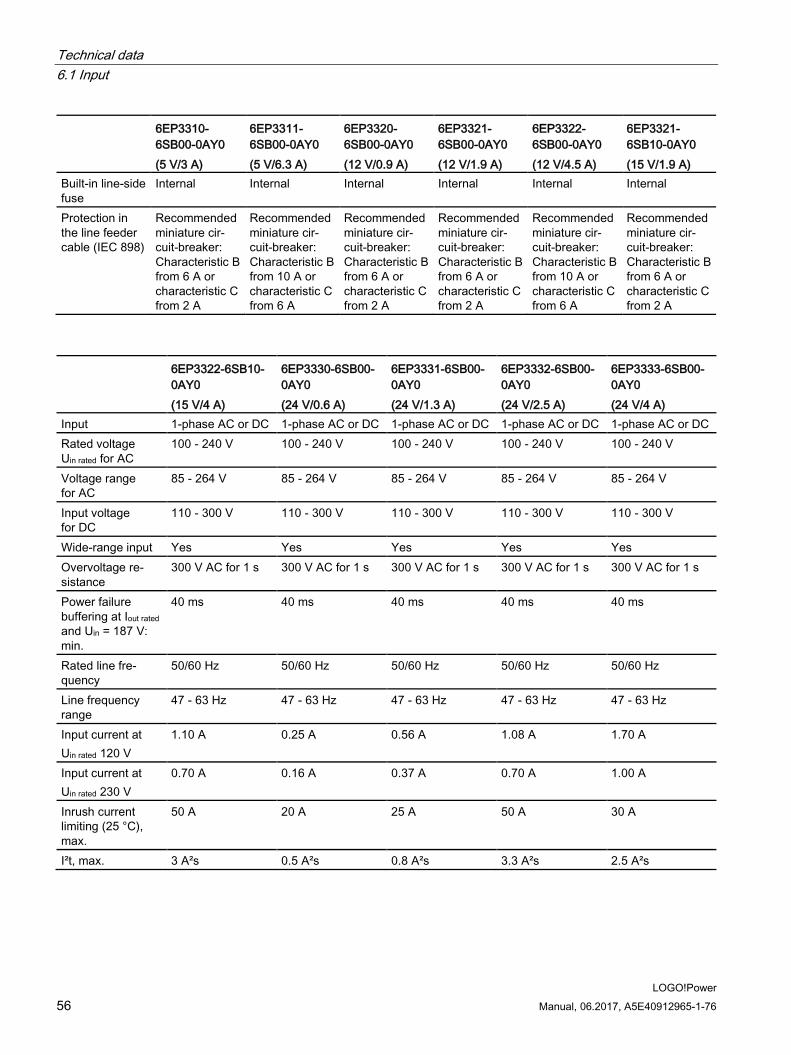
6EP3310-6SB00-0AY0 (5 V/3 A)
6EP3311-6SB00-0AY0 (5 V/6.3 A)
6EP3320-6SB00-0AY0 (12 V/0.9 A)
6EP3321-6SB00-0AY0 (12 V/1.9 A)
6EP3322-6SB00-0AY0 (12 V/4.5 A)
6EP3321-6SB10-0AY0 (15 V/1.9 A)
Built-in line-side fuse
Internal Internal Internal Internal Internal Internal
Protection in the line feeder cable (IEC 898)
Recommended miniature cir-cuit-breaker: Characteristic B from 6 A or characteristic C from 2 A
Recommended miniature cir-cuit-breaker: Characteristic B from 10 A or characteristic C from 6 A
Recommended miniature cir-cuit-breaker: Characteristic B from 6 A or characteristic C from 2 A
Recommended miniature cir-cuit-breaker: Characteristic B from 6 A or characteristic C from 2 A
Recommended miniature cir-cuit-breaker: Characteristic B from 10 A or characteristic C from 6 A
Recommended miniature cir-cuit-breaker: Characteristic B from 6 A or characteristic C from 2 A
6EP3322-6SB10-0AY0 (15 V/4 A)
6EP3330-6SB00-0AY0 (24 V/0.6 A)
6EP3331-6SB00-0AY0 (24 V/1.3 A)
6EP3332-6SB00-0AY0 (24 V/2.5 A)
6EP3333-6SB00-0AY0 (24 V/4 A)
Input 1-phase AC or DC 1-phase AC or DC 1-phase AC or DC 1-phase AC or DC 1-phase AC or DC Rated voltage Uin rated for AC
100 - 240 V 100 - 240 V 100 - 240 V 100 - 240 V 100 - 240 V
Voltage range for AC
85 - 264 V 85 - 264 V 85 - 264 V 85 - 264 V 85 - 264 V
Input voltage for DC
110 - 300 V 110 - 300 V 110 - 300 V 110 - 300 V 110 - 300 V
Wide-range input Yes Yes Yes Yes Yes Overvoltage re-sistance
300 V AC for 1 s 300 V AC for 1 s 300 V AC for 1 s 300 V AC for 1 s 300 V AC for 1 s
Power failure buffering at Iout rated and Uin = 187 V: min.
40 ms 40 ms 40 ms 40 ms 40 ms
Rated line fre-quency
50/60 Hz 50/60 Hz 50/60 Hz 50/60 Hz 50/60 Hz
Line frequency range
47 - 63 Hz 47 - 63 Hz 47 - 63 Hz 47 - 63 Hz 47 - 63 Hz
Input current at Uin rated 120 V
1.10 A 0.25 A 0.56 A 1.08 A 1.70 A
Input current at Uin rated 230 V
0.70 A 0.16 A 0.37 A 0.70 A 1.00 A
Inrush current limiting (25 °C), max.
50 A 20 A 25 A 50 A 30 A
I²t, max. 3 A²s 0.5 A²s 0.8 A²s 3.3 A²s 2.5 A²s
Technical data 6.1 Input
LOGO!Power Manual, 06.2017, A5E40912965-1-76 57
6EP3322-6SB10-0AY0 (15 V/4 A)
6EP3330-6SB00-0AY0 (24 V/0.6 A)
6EP3331-6SB00-0AY0 (24 V/1.3 A)
6EP3332-6SB00-0AY0 (24 V/2.5 A)
6EP3333-6SB00-0AY0 (24 V/4 A)
Built-in line-side fuse
Internal Internal Internal Internal Internal
Protection in the line feeder cable (IEC 898)
Recommended miniature circuit-breaker: Charac-teristic B from 10 A or character-istic C from 6 A
Recommended miniature circuit-breaker: Charac-teristic B from 6 A or characteristic C from 2 A
Recommended miniature circuit-breaker: Charac-teristic B from 6 A or characteristic C from 2 A
Recommended miniature circuit-breaker: Charac-teristic B from 10 A or character-istic C from 6 A
Recommended miniature circuit-breaker: Charac-teristic B from 10 A or character-istic C from 6 A
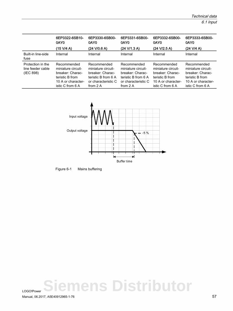
Figure 6-1 Mains buffering
Siemens Distributor
Technical data 6.2 Output
LOGO!Power 58 Manual, 06.2017, A5E40912965-1-76
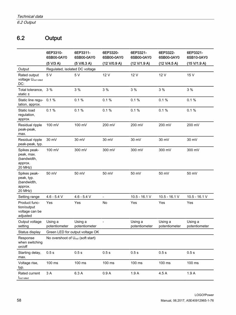
6.2 Output
6EP3310-6SB00-0AY0 (5 V/3 A)
6EP3311-6SB00-0AY0 (5 V/6.3 A)
6EP3320-6SB00-0AY0 (12 V/0.9 A)
6EP3321-6SB00-0AY0 (12 V/1.9 A)
6EP3322-6SB00-0AY0 (12 V/4.5 A)
6EP3321-6SB10-0AY0 (15 V/1.9 A)
Output Regulated, isolated DC voltage Rated output voltage Uout rated DC:
5 V 5 V 12 V 12 V 12 V 15 V
Total tolerance, static ±
3 % 3 % 3 % 3 % 3 % 3 %
Static line regu-lation, approx.
0.1 % 0.1 % 0.1 % 0.1 % 0.1 % 0.1 %
Static load regulation, approx.
0.1 % 0.1 % 0.1 % 0.1 % 0.1 % 0.1 %
Residual ripple peak-peak, max.
100 mV 100 mV 200 mV 200 mV 200 mV 200 mV
Residual ripple peak-peak, typ.
30 mV 30 mV 30 mV 30 mV 30 mV 30 mV
Spikes peak-peak, max. (bandwidth, approx. 20 MHz)
100 mV 300 mV 300 mV 300 mV 300 mV 300 mV
Spikes peak-peak, typ. (bandwidth, approx. 20 MHz)
50 mV 50 mV 50 mV 50 mV 50 mV 50 mV
Setting range 4.6 - 5.4 V 4.6 - 5.4 V - 10.5 - 16.1 V 10.5 - 16.1 V 10.5 - 16.1 V Product func-tion/output voltage can be adjusted
Yes Yes No Yes Yes Yes
Output voltage setting
Using a potentiometer
Using a potentiometer
- Using a potentiometer
Using a potentiometer
Using a potentiometer
Status display Green LED for output voltage OK Response when switching on/off
No overshoot of Uout (soft start)
Starting delay, max.
0.5 s 0.5 s 0.5 s 0.5 s 0.5 s 0.5 s
Voltage rise, typ.
100 ms 100 ms 100 ms 100 ms 100 ms 100 ms
Rated current Iout rated
3 A 6.3 A 0.9 A 1.9 A 4.5 A 1.9 A
Technical data 6.2 Output
LOGO!Power Manual, 06.2017, A5E40912965-1-76 59
6EP3310-6SB00-0AY0 (5 V/3 A)
6EP3311-6SB00-0AY0 (5 V/6.3 A)
6EP3320-6SB00-0AY0 (12 V/0.9 A)
6EP3321-6SB00-0AY0 (12 V/1.9 A)
6EP3322-6SB00-0AY0 (12 V/4.5 A)
6EP3321-6SB10-0AY0 (15 V/1.9 A)
Current range • Remark
0 - 3 A 55 … 70 °C: Derating 2 %/K
0 - 6.3 A 55 … 70 °C: Derating 2 %/K
0 - 0.9 A 55 … 70 °C: Derating 2 %/K
0 - 1.9 A 55 … 70 °C: Derating 2 %/K
0 - 4.5 A 55 … 70 °C: Derating 2 %/K
0 - 1.9 A 55 … 70 °C: Derating 2 %/K
Output active power/typical
15 W 31.5 W 10.8 W 22.8 W 54 W 28.5 W
Can be con-nected in paral-lel to increase the power rat-ing
Yes Yes No Yes Yes Yes
Number of devices that can be con-nected in paral-lel, quantity
2 2 - 2 2 2
Output charac-teristic
see Figure 6-3 Output character-istic (Page 61)
see Figure 6-4 Output charac-teristic (12 V-0.9 A) (Page 62)
see Figure 6-3 Output characteristic (Page 61)
6EP3322-6SB10-0AY0 (15 V/4 A)
6EP3330-6SB00-0AY0 (24 V/0.6 A)
6EP3331-6SB00-0AY0 (24 V/1.3 A)
6EP3332-6SB00-0AY0 (24 V/2.5 A)
6EP3333-6SB00-0AY0 (24 V/4 A)
Output Regulated, isolated DC voltage Rated output volt-age Uout rated DC:
15 V 24 V 24 V 24 V 24 V
Total tolerance, static ±
3 % 3 % 3 % 3 % 3 %
Static line regula-tion, approx.
0.1 % 0.1 % 0.1 % 0.1 % 0.1 %
Static load regula-tion, approx.
0.1 % 0.1 % 0.1 % 0.1 % 0.1 %
Residual ripple peak-peak, max.
200 mV 200 mV 200 mV 200 mV 200 mV
Residual ripple peak-peak, typ.
30 mV 30 mV 30 mV 30 mV 30 mV
Spikes peak-peak, max. (bandwidth, approx. 20 MHz)
300 mV 300 mV 300 mV 300 mV 300 mV
Spikes peak-peak, typ. (bandwidth, approx. 20 MHz)
50 mV 50 mV 50 mV 50 mV 50 mV
Setting range 10.5 - 16.1 V - 22.2 - 26.4 V 22.2 - 26.4 V 22.2 - 26.4 V
Siemens Distributor
Technical data 6.2 Output
LOGO!Power 60 Manual, 06.2017, A5E40912965-1-76
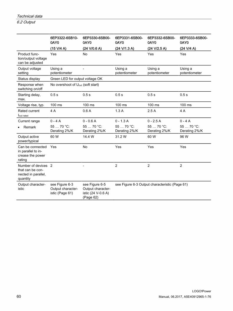
6EP3322-6SB10-0AY0 (15 V/4 A)
6EP3330-6SB00-0AY0 (24 V/0.6 A)
6EP3331-6SB00-0AY0 (24 V/1.3 A)
6EP3332-6SB00-0AY0 (24 V/2.5 A)
6EP3333-6SB00-0AY0 (24 V/4 A)
Product func-tion/output voltage can be adjusted
Yes No Yes Yes Yes
Output voltage setting
Using a potentiometer
- Using a potentiometer
Using a potentiometer
Using a potentiometer
Status display Green LED for output voltage OK Response when switching on/off
No overshoot of Uout (soft start)
Starting delay, max.
0.5 s 0.5 s 0.5 s 0.5 s 0.5 s
Voltage rise, typ. 100 ms 100 ms 100 ms 100 ms 100 ms Rated current Iout rated
4 A 0.6 A 1.3 A 2.5 A 4 A
Current range • Remark
0 - 4 A 55 … 70 °C: Derating 2%/K
0 - 0.6 A 55 … 70 °C: Derating 2%/K
0 - 1.3 A 55 … 70 °C: Derating 2%/K
0 - 2.5 A 55 … 70 °C: Derating 2%/K
0 - 4 A 55 … 70 °C: Derating 2%/K
Output active power/typical
60 W 14.4 W 31.2 W 60 W 96 W
Can be connected in parallel to in-crease the power rating
Yes No Yes Yes Yes
Number of devices that can be con-nected in parallel, quantity
2 - 2 2 2
Output character-istic
see Figure 6-3 Output character-istic (Page 61)
see Figure 6-5 Output character-istic (24 V-0.6 A) (Page 62)
see Figure 6-3 Output characteristic (Page 61)
Technical data 6.2 Output
LOGO!Power Manual, 06.2017, A5E40912965-1-76 61
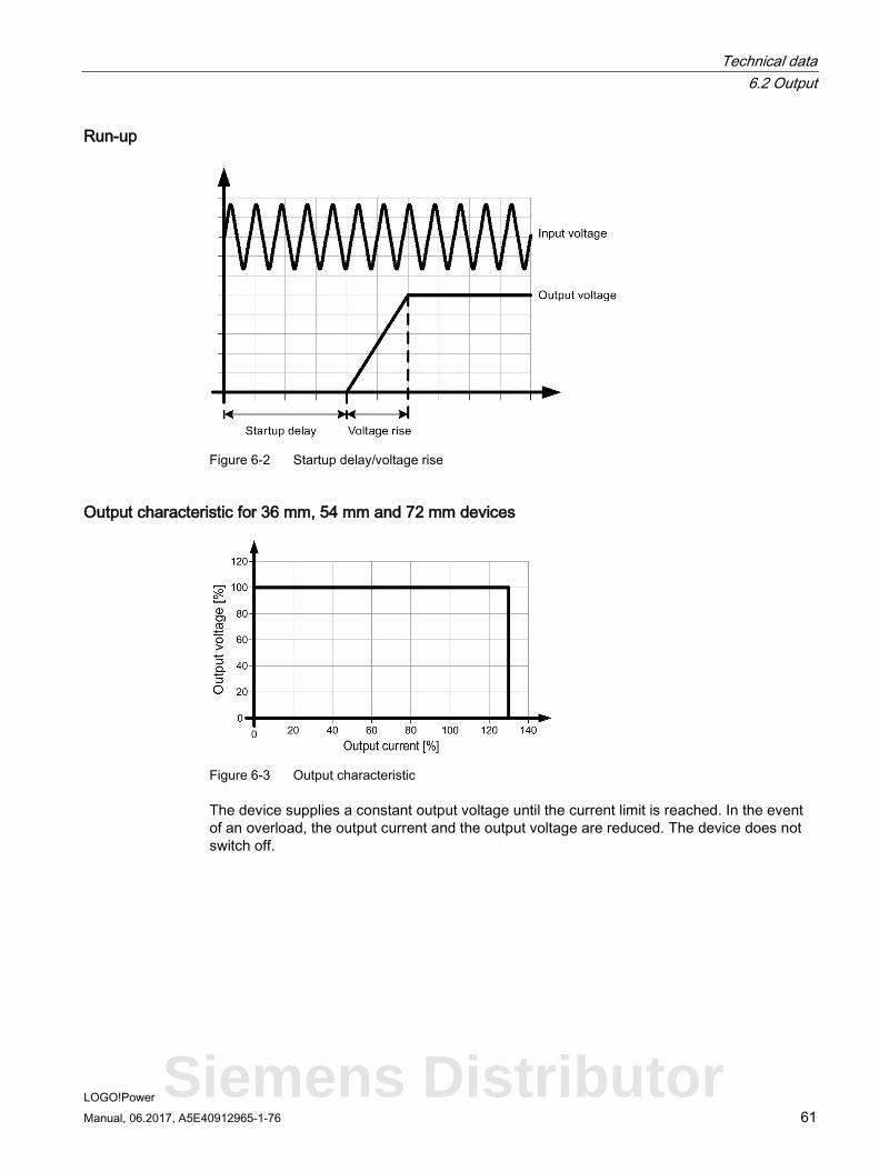
Run-up
Figure 6-2 Startup delay/voltage rise
Output characteristic for 36 mm, 54 mm and 72 mm devices
Figure 6-3 Output characteristic
The device supplies a constant output voltage until the current limit is reached. In the event of an overload, the output current and the output voltage are reduced. The device does not switch off.
Siemens Distributor
Technical data 6.2 Output
LOGO!Power 62 Manual, 06.2017, A5E40912965-1-76
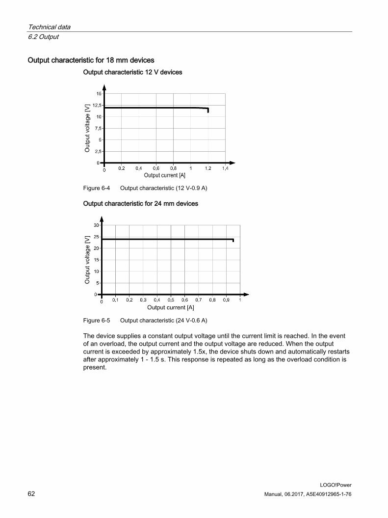
Output characteristic for 18 mm devices Output characteristic 12 V devices
Figure 6-4 Output characteristic (12 V-0.9 A)
Output characteristic for 24 mm devices
Figure 6-5 Output characteristic (24 V-0.6 A)
The device supplies a constant output voltage until the current limit is reached. In the event of an overload, the output current and the output voltage are reduced. When the output current is exceeded by approximately 1.5x, the device shuts down and automatically restarts after approximately 1 - 1.5 s. This response is repeated as long as the overload condition is present.
Technical data 6.3 Efficiency and power loss
LOGO!Power Manual, 06.2017, A5E40912965-1-76 63
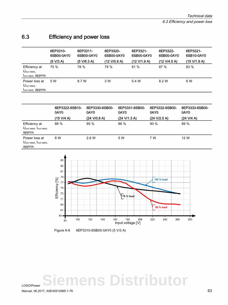
6.3 Efficiency and power loss
6EP3310-6SB00-0AY0 (5 V/3 A)
6EP3311-6SB00-0AY0 (5 V/6.3 A)
6EP3320-6SB00-0AY0 (12 V/0.9 A)
6EP3321-6SB00-0AY0 (12 V/1.9 A)
6EP3322-6SB00-0AY0 (12 V/4.5 A)
6EP3321-6SB10-0AY0 (15 V/1.9 A)
Efficiency at Uout rated, Iout rated, approx.
75 % 78 % 78 % 81 % 87 % 83 %
Power loss at Uout rated, Iout rated, approx.
5 W 8.7 W 3 W 5.4 W 8.2 W 6 W
6EP3322-6SB10-0AY0 (15 V/4 A)
6EP3330-6SB00-0AY0 (24 V/0.6 A)
6EP3331-6SB00-0AY0 (24 V/1.3 A)
6EP3332-6SB00-0AY0 (24 V/2.5 A)
6EP3333-6SB00-0AY0 (24 V/4 A)
Efficiency at Uout rated, Iout rated, approx.
88 % 85 % 86 % 90 % 89 %
Power loss at Uout rated, Iout rated, approx.
8 W 2.6 W 5 W 7 W 12 W
Figure 6-6 6EP3310-6SB00-0AY0 (5 V/3 A)
Siemens Distributor
Technical data 6.3 Efficiency and power loss
LOGO!Power 64 Manual, 06.2017, A5E40912965-1-76
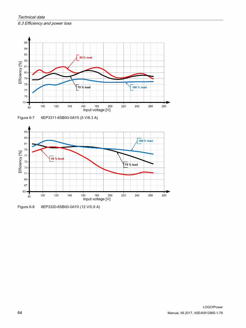
Figure 6-7 6EP3311-6SB00-0AY0 (5 V/6.3 A)
Figure 6-8 6EP3320-6SB00-0AY0 (12 V/0.9 A)
Technical data 6.3 Efficiency and power loss
LOGO!Power Manual, 06.2017, A5E40912965-1-76 65
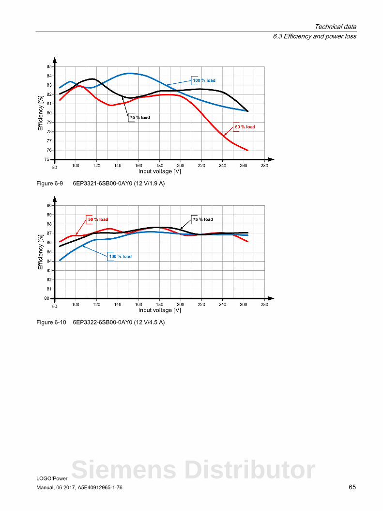
Figure 6-9 6EP3321-6SB00-0AY0 (12 V/1.9 A)
Figure 6-10 6EP3322-6SB00-0AY0 (12 V/4.5 A)
Siemens Distributor
Technical data 6.3 Efficiency and power loss
LOGO!Power 66 Manual, 06.2017, A5E40912965-1-76
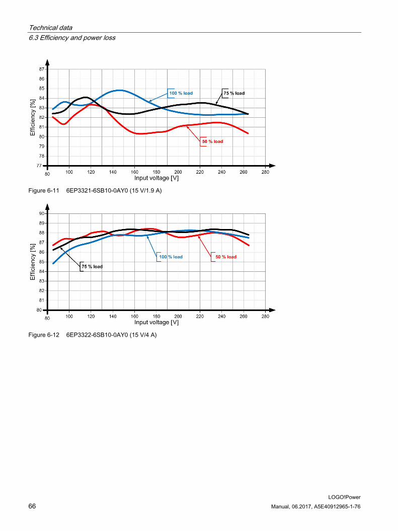
Figure 6-11 6EP3321-6SB10-0AY0 (15 V/1.9 A)
Figure 6-12 6EP3322-6SB10-0AY0 (15 V/4 A)
Technical data 6.3 Efficiency and power loss
LOGO!Power Manual, 06.2017, A5E40912965-1-76 67
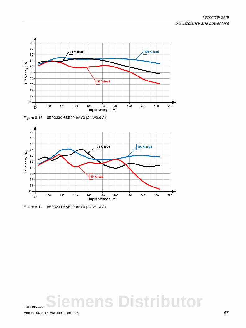
Figure 6-13 6EP3330-6SB00-0AY0 (24 V/0.6 A)
Figure 6-14 6EP3331-6SB00-0AY0 (24 V/1.3 A)
Siemens Distributor
Technical data 6.3 Efficiency and power loss
LOGO!Power 68 Manual, 06.2017, A5E40912965-1-76
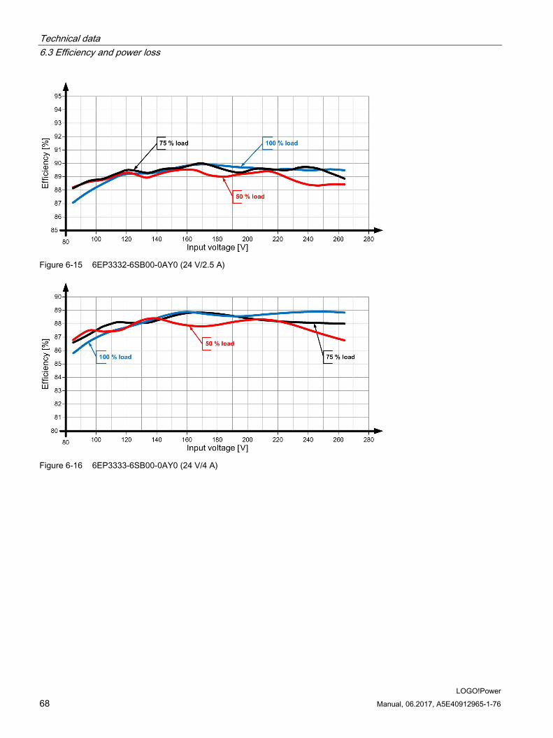
Figure 6-15 6EP3332-6SB00-0AY0 (24 V/2.5 A)
Figure 6-16 6EP3333-6SB00-0AY0 (24 V/4 A)
Technical data 6.4 Closed-loop control
LOGO!Power Manual, 06.2017, A5E40912965-1-76 69
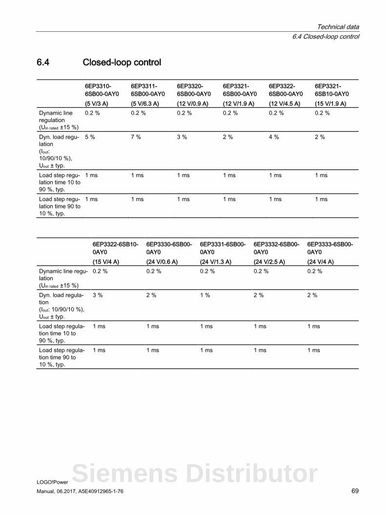
6.4 Closed-loop control
6EP3310-6SB00-0AY0 (5 V/3 A)
6EP3311-6SB00-0AY0 (5 V/6.3 A)
6EP3320-6SB00-0AY0 (12 V/0.9 A)
6EP3321-6SB00-0AY0 (12 V/1.9 A)
6EP3322-6SB00-0AY0 (12 V/4.5 A)
6EP3321-6SB10-0AY0 (15 V/1.9 A)
Dynamic line regulation (Uin rated ±15 %)
0.2 % 0.2 % 0.2 % 0.2 % 0.2 % 0.2 %
Dyn. load regu-lation (Iout: 10/90/10 %), Uout ± typ.
5 % 7 % 3 % 2 % 4 % 2 %
Load step regu-lation time 10 to 90 %, typ.
1 ms 1 ms 1 ms 1 ms 1 ms 1 ms
Load step regu-lation time 90 to 10 %, typ.
1 ms 1 ms 1 ms 1 ms 1 ms 1 ms
6EP3322-6SB10-0AY0 (15 V/4 A)
6EP3330-6SB00-0AY0 (24 V/0.6 A)
6EP3331-6SB00-0AY0 (24 V/1.3 A)
6EP3332-6SB00-0AY0 (24 V/2.5 A)
6EP3333-6SB00-0AY0 (24 V/4 A)
Dynamic line regu-lation (Uin rated ±15 %)
0.2 % 0.2 % 0.2 % 0.2 % 0.2 %
Dyn. load regula-tion (Iout: 10/90/10 %), Uout ± typ.
3 % 2 % 1 % 2 % 2 %
Load step regula-tion time 10 to 90 %, typ.
1 ms 1 ms 1 ms 1 ms 1 ms
Load step regula-tion time 90 to 10 %, typ.
1 ms 1 ms 1 ms 1 ms 1 ms
Siemens Distributor
Technical data 6.5 Protection and monitoring
LOGO!Power 70 Manual, 06.2017, A5E40912965-1-76
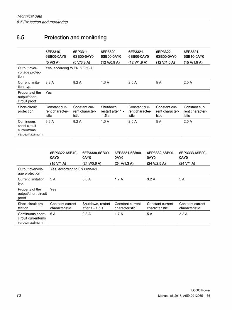
6.5 Protection and monitoring
6EP3310-6SB00-0AY0 (5 V/3 A)
6EP3311-6SB00-0AY0 (5 V/6.3 A)
6EP3320-6SB00-0AY0 (12 V/0.9 A)
6EP3321-6SB00-0AY0 (12 V/1.9 A)
6EP3322-6SB00-0AY0 (12 V/4.5 A)
6EP3321-6SB10-0AY0 (15 V/1.9 A)
Output over-voltage protec-tion
Yes, according to EN 60950-1
Current limita-tion, typ.
3.8 A 8.2 A 1.3 A 2.5 A 5 A 2.5 A
Property of the output/short-circuit proof
Yes
Short-circuit protection
Constant cur-rent character-istic
Constant cur-rent character-istic
Shutdown, restart after 1 - 1.5 s
Constant cur-rent character-istic
Constant cur-rent character-istic
Constant cur-rent character-istic
Continuous short-circuit current/rms value/maximum
3.8 A 8.2 A 1.3 A 2.5 A 5 A 2.5 A
6EP3322-6SB10-0AY0 (15 V/4 A)
6EP3330-6SB00-0AY0 (24 V/0.6 A)
6EP3331-6SB00-0AY0 (24 V/1.3 A)
6EP3332-6SB00-0AY0 (24 V/2.5 A)
6EP3333-6SB00-0AY0 (24 V/4 A)
Output overvolt-age protection
Yes, according to EN 60950-1
Current limitation, typ.
5 A 0.8 A 1.7 A 3.2 A 5 A
Property of the output/short-circuit proof
Yes
Short-circuit pro-tection
Constant current characteristic
Shutdown, restart after 1 - 1.5 s
Constant current characteristic
Constant current characteristic
Constant current characteristic
Continuous short-circuit current/rms value/maximum
5 A 0.8 A 1.7 A 5 A 3.2 A
Technical data 6.6 MTBF
LOGO!Power Manual, 06.2017, A5E40912965-1-76 71
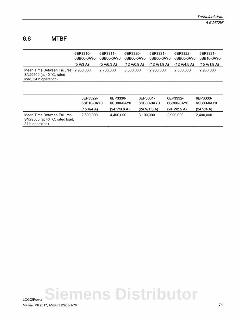
6.6 MTBF
6EP3310-6SB00-0AY0 (5 V/3 A)
6EP3311-6SB00-0AY0 (5 V/6.3 A)
6EP3320-6SB00-0AY0 (12 V/0.9 A)
6EP3321-6SB00-0AY0 (12 V/1.9 A)
6EP3322-6SB00-0AY0 (12 V/4.5 A)
6EP3321-6SB10-0AY0 (15 V/1.9 A)
Mean Time Between Failures SN29500 (at 40 °C, rated load, 24 h operation)
2,900,000 2,700,000 3,800,000 2,900,000 2,600,000 2,900,000
6EP3322-6SB10-0AY0 (15 V/4 A)
6EP3330-6SB00-0AY0 (24 V/0.6 A)
6EP3331-6SB00-0AY0 (24 V/1.3 A)
6EP3332-6SB00-0AY0 (24 V/2.5 A)
6EP3333-6SB00-0AY0 (24 V/4 A)
Mean Time Between Failures SN29500 (at 40 °C, rated load, 24 h operation)
2,600,000 4,400,000 3,100,000 2,900,000 2,400,000
Siemens Distributor
Technical data 6.7 Mechanical system
LOGO!Power 72 Manual, 06.2017, A5E40912965-1-76
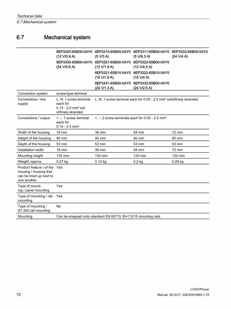
6.7 Mechanical system
6EP3320-6SB00-0AY0 (12 V/0.9 A) 6EP3330-6SB00-0AY0 (24 V/0.6 A)
6EP3310-6SB00-0AY0 (5 V/3 A) 6EP3321-6SB00-0AY0 (12 V/1.9 A) 6EP3321-6SB10-0AY0 (15 V/1.9 A) 6EP3331-6SB00-0AY0 (24 V/1.3 A)
6EP3311-6SB00-0AY0 (5 V/6.3 A) 6EP3322-6SB00-0AY0 (12 V/4.5 A) 6EP3322-6SB10-0AY0 (15 V/4 A) 6EP3332-6SB00-0AY0 (24 V/2.5 A)
6EP3333-6SB00-0AY0 (24 V/4 A)
Connection system screw-type terminal Connections / line supply
L, N: 1 screw terminal each for 0.14 - 2.5 mm² sol-id/finely stranded
L, N: 1 screw terminal each for 0.05 - 2.5 mm² solid/finely stranded
Connections / output +, -: 1 screw terminal each for 0.14 - 2.5 mm²
+, -: 2 screw terminals each for 0.05 - 2.5 mm²
Width of the housing 18 mm 36 mm 54 mm 72 mm Height of the housing 90 mm 90 mm 90 mm 90 mm Depth of the housing 53 mm 53 mm 53 mm 53 mm Installation width 18 mm 36 mm 54 mm 72 mm Mounting height 130 mm 130 mm 130 mm 130 mm Weight, approx. 0.07 kg 0.12 kg 0.2 kg 0.29 kg Product feature / of the housing / housing that can be lined up next to one another
Yes
Type of mount-ing / panel mounting
Yes
Type of mounting / rail mounting
Yes
Type of mounting / S7-300 rail mounting
No
Mounting Can be snapped onto standard EN 60715 35×7,5/15 mounting rails
Technical data 6.8 Dimension drawing
LOGO!Power Manual, 06.2017, A5E40912965-1-76 73
6.8 Dimension drawing See Section Dimensions and weight (Page 17)
CAD data that can be downloaded from the Internet:
6EP3310-6SB00-0AY0 (http://www.automation.siemens.com/bilddb/index.aspx?gridview=view2&objkey=G_KT01_XX_01275&showdetail=true&view=Search)
6EP3311-6SB00-0AY0 (http://www.automation.siemens.com/bilddb/index.aspx?gridview=view2&objkey=G_KT01_XX_01278&showdetail=true&view=Search)
6EP3320-6SB00-0AY0 (http://www.automation.siemens.com/bilddb/index.aspx?gridview=view2&objkey=G_KT01_XX_01306&showdetail=true&view=Search)
6EP3321-6SB00-0AY0 (http://www.automation.siemens.com/bilddb/index.aspx?gridview=view2&objkey=G_KT01_XX_01281&showdetail=true&view=Search)
6EP3322-6SB00-0AY0 (http://www.automation.siemens.com/bilddb/index.aspx?gridview=view2&objkey=G_KT01_XX_01284&showdetail=true&view=Search)
6EP3321-6SB10-0AY0 (http://www.automation.siemens.com/bilddb/index.aspx?gridview=view2&objkey=G_KT01_XX_01287&showdetail=true&view=Search)
6EP3322-6SB10-0AY0 (http://www.automation.siemens.com/bilddb/index.aspx?gridview=view2&objkey=G_KT01_XX_01290&showdetail=true&view=Search)
6EP3330-6SB00-0AY0 (http://www.automation.siemens.com/bilddb/index.aspx?gridview=view2&objkey=G_KT01_XX_01303&showdetail=true&view=Search)
6EP3331-6SB00-0AY0 (http://www.automation.siemens.com/bilddb/index.aspx?gridview=view2&objkey=G_KT01_XX_01293&showdetail=true&view=Search)
6EP3332-6SB00-0AY0 (http://www.automation.siemens.com/bilddb/index.aspx?gridview=view2&objkey=G_KT01_XX_01296&showdetail=true&view=Search)
6EP3333-6SB00-0AY0 (http://www.automation.siemens.com/bilddb/index.aspx?gridview=view2&objkey=G_KT01_XX_01299&showdetail=true&view=Search)
Siemens Distributor
Technical data 6.8 Dimension drawing
LOGO!Power 74 Manual, 06.2017, A5E40912965-1-76
LOGO!Power Manual, 06.2017, A5E40912965-1-76 75
Safety, approvals, EMC 7 7.1 Safety
6EP3310-6SB00-0AY0 (5 V/3 A) 6EP3311-6SB00-0AY0 (5 V/6.3 A) 6EP3320-6SB00-0AY0 (12 V/0.9 A) 6EP3321-6SB00-0AY0 (12 V/1.9 A) 6EP3322-6SB00-0AY0 (12 V/4.5 A) 6EP3321-6SB10-0AY0 (15 V/1.9 A)
6EP3322-6SB10-0AY0 (15 V/4 A) 6EP3330-6SB00-0AY0 (24 V/0.6 A) 6EP3331-6SB00-0AY0 (24 V/1.3 A) 6EP3332-6SB00-0AY0 (24 V/2.5 A) 6EP3333-6SB00-0AY0 (24 V/4 A)
Primary/secondary galvanic isolation Yes Electrical isolation SELV output voltage Uout acc. to EN 60950-1 and EN 50178 Protection class Class II (without protective conductor) Degree of protection (EN 60529) IP20 Test voltage See Section Test voltage (Page 76)
Siemens Distributor
Safety, approvals, EMC 7.2 Test voltage
LOGO!Power 76 Manual, 06.2017, A5E40912965-1-76
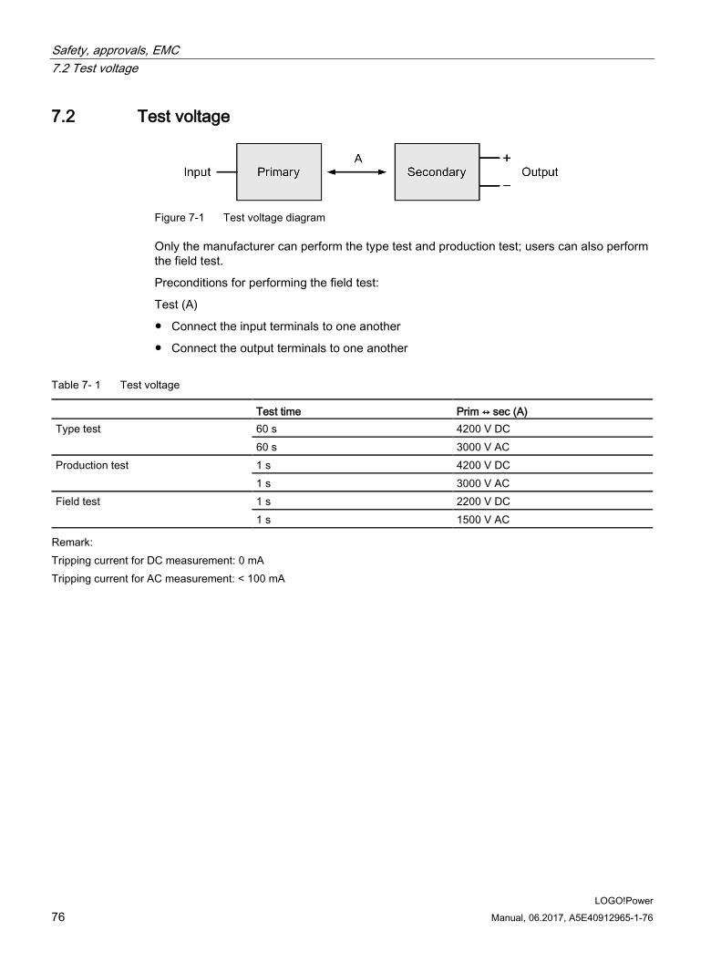
7.2 Test voltage
Figure 7-1 Test voltage diagram
Only the manufacturer can perform the type test and production test; users can also perform the field test.
Preconditions for performing the field test:
Test (A)
● Connect the input terminals to one another
● Connect the output terminals to one another
Table 7- 1 Test voltage
Test time Prim ↔ sec (A) Type test 60 s 4200 V DC
60 s 3000 V AC Production test 1 s 4200 V DC
1 s 3000 V AC Field test 1 s 2200 V DC
1 s 1500 V AC Remark:
Tripping current for DC measurement: 0 mA Tripping current for AC measurement: < 100 mA
Safety, approvals, EMC 7.3 Certifications
LOGO!Power Manual, 06.2017, A5E40912965-1-76 77
7.3 Certifications
Certifications 6EP3310-6SB00-0AY0 (5 V/3 A) 6EP3321-6SB00-0AY0 (12 V/1.9 A) 6EP3321-6SB10-0AY0 (15 V/1.9 A) 6EP3331-6SB00-0AY0 (24 V/1.3 A)
6EP3320-6SB00-0AY0 (12 V/0.9 A) 6EP3322-6SB00-0AY0 (12 V/4.5 A) 6EP3322-6SB10-0AY0 (15 V/4 A) 6EP3330-6SB00-0AY0 (24 V/0.6 A) 6EP3332-6SB00-0AY0 (24 V/2.5 A)
6EP3311-6SB00-0AY0 (5 V/6.3 A) 6EP3333-6SB00-0AY0 (24 V/4 A)
CE marking Yes Yes Yes UL/cUL approval cULus-Listed (UL 508, CSA C22.2 No.107.1),
File E197259 NEC class2 (to UL 60950-1/UL 1310), File E151273
cULus-Listed (UL 508, CSA C22.2 No.107.1), File E197259
UL/CSA approval cURus-Recognized (UL 60950-1, CSA C22.2 No. 60950-1) File E151273 CSA 22.2 N060950 cCSAus
FM Class I, Div. 2, Group ABCD, T4 being prepared CB approval Yes Yes Yes Explosion protection ATEX II 3G Ex ic nA IIC T4
UL/cUL: ANSI/ISA-12.12.01-2015) Class I, Div. 2, Group ABCD, T4
ATEX II 3G Ex ic nA IIC T3 UL/cUL: ANSI/ISA-12.12.01-2015) Class I, Div. 2, Group ABCD, T4
IECEx approval Yes Yes Yes SEMI F47 compliance 208 V-240 V IEC 61000-4-11 EC 61000-4-11 EC 61000-4-11 Marine approval 6EP3310-6SB00-0AY0, 6EP3311-6SB00-0AY0, 6EP3320-6SB00-0AY0
6EP3321-6SB00-0AY0, 6EP3322-6SB00-0AY0 DNV-GL, ABS being prepared 6EP3321-6SB10-0AY0, 6EP3322-6SB10-0AY0, 6EP3330-6SB00-0AY0 6EP3331-6SB00-0AY0, 6EP3332-6SB00-0AY0, 6EP3333-6SB00-0AY0 DNV-GL, ABS, BV, LRS being prepared
Siemens Distributor
Safety, approvals, EMC 7.4 EMC
LOGO!Power 78 Manual, 06.2017, A5E40912965-1-76
7.4 EMC
6EP3310-6SB00-0AY0 (5 V/3 A) 6EP3311-6SB00-0AY0 (5 V/6.3 A) 6EP3320-6SB00-0AY0 (12 V/0.9 A) 6EP3321-6SB00-0AY0 (12 V/1.9 A) 6EP3322-6SB00-0AY0 (12 V/4.5 A) 6EP3321-6SB10-0AY0 (15 V/1.9 A) 6EP3322-6SB10-0AY0 (15 V/4 A) 6EP3330-6SB00-0AY0 (24 V/0.6 A) 6EP3331-6SB00-0AY0 (24 V/1.3 A) 6EP3332-6SB00-0AY0 (24 V/2.5 A) 6EP3333-6SB00-0AY0 (24 V/4 A)
Generic standards
EN 61000-6-2 Immunity for industrial environments EN 61000-6-3 Emission for residential areas
Electrostatic discharges EN 61000-4-2 8 kV contact, 8 kV air Electromagnetic fields EN 61000-4-3 80 - 1000 MHz 10 V/m
1000 - 2000 MHz 3 V/m 2000 - 2700 MHz 1 V/m
High-speed transient disturbance varia-bles (burst)
EN 61000-4-4 4 kV on line connections 2 kV at DC output
Power surges EN 61000-4-5 2 kV symmetrical on line connections 4 kV asymmetrical on line connections 500 V symmetrical/asymmetrical on DC output cables
High-frequency fields EN 61000-4-6 10 V; 0.15 - 80 MHz Voltage dips EN 61000-4-11 100% for 20 ms
60% for 200 ms 30% for 500 ms
Voltage interruptions EN 61000-4-11 100% for 5000 ms Emitted interference EN 55022 Class B Line harmonics limitation EN 61000-3-2 Not applicable Noise immunity EN 61000-6-2
LOGO!Power Manual, 06.2017, A5E40912965-1-76 79
Ambient conditions 8
6EP3310-6SB00-0AY0 (5 V/3 A) 6EP3311-6SB00-0AY0 (5 V/6.3 A) 6EP3320-6SB00-0AY0 (12 V/0.9 A) 6EP3321-6SB00-0AY0 (12 V/1.9 A) 6EP3322-6SB00-0AY0 (12 V/4.5 A) 6EP3321-6SB10-0AY0 (15 V/1.9 A)
6EP3322-6SB10-0AY0 (15 V/4 A) 6EP3330-6SB00-0AY0 (24 V/0.6 A) 6EP3331-6SB00-0AY0 (24 V/1.3 A) 6EP3332-6SB00-0AY0 (24 V/2.5 A) 6EP3333-6SB00-0AY0 (24 V/4 A)
Ambient temperature -25 ... 70 °C for natural convection (self convection) Tested according to: • EN 60068-2-1 Cold • EN 60068-2-2 Dry heat • EN 60068-2-78 Humid heat, constant • EN 60068-2-14 Temperature change
Transport and storage temperature -40 ... 85 °C Tests (packed for shipping) according to: • EN 60068-2-1 Cold • EN 60068-2-2 Dry heat • EN 60068-2-30 Humid heat, cyclic
Humidity class Climatic class 3K3 according to EN 60721, 5 - 95 % no condensation Degree of pollution 2 Mechanical stressing in operation Tested according to:
• EN 60068-2-6 Vibration, test Fc – 7 mm deflection in the range 5 – 9 Hz – 2 g acceleration in the range 9 – 150 Hz
• EN 60068-2-27 Shock, test Ea – Acceleration 150 m/s2, test duration 11 ms
Siemens Distributor
Ambient conditions
LOGO!Power 80 Manual, 06.2017, A5E40912965-1-76
6EP3310-6SB00-0AY0 (5 V/3 A) 6EP3311-6SB00-0AY0 (5 V/6.3 A) 6EP3320-6SB00-0AY0 (12 V/0.9 A) 6EP3321-6SB00-0AY0 (12 V/1.9 A) 6EP3322-6SB00-0AY0 (12 V/4.5 A) 6EP3321-6SB10-0AY0 (15 V/1.9 A)
6EP3322-6SB10-0AY0 (15 V/4 A) 6EP3330-6SB00-0AY0 (24 V/0.6 A) 6EP3331-6SB00-0AY0 (24 V/1.3 A) 6EP3332-6SB00-0AY0 (24 V/2.5 A) 6EP3333-6SB00-0AY0 (24 V/4 A)
Damaging gases Tested according to: • EN 60068-2-42 Sulfur dioxide: 10 cm3/m3, 4 days • EN 60068-2-43 Hydrogen sulfide: 1 cm3/m3, 4 days
Atmospheric pressure Operation: • 1080 - 795 hPa (-1000 - 2000 m) • For operation at altitudes of 2000 m up to 6000 m above sea level:
output power must be derated by -7.5% / 1000 m or the ambient temperature must be reduced by 5 K / 1000 m see Figure 4-12 Mounting height derating (Page 27)
• Overvoltage category: III up to 2000 m (EN 50178) II from 2000 m up to 6000 m (EN 50178)
Storage: • 1080 - 660 hPa (-1000 - 3500 m)
LOGO!Power Manual, 06.2017, A5E40912965-1-76 81
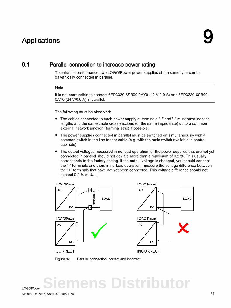
Applications 9 9.1 Parallel connection to increase power rating
To enhance performance, two LOGO!Power power supplies of the same type can be galvanically connected in parallel.
Note
It is not permissible to connect 6EP3320-6SB00-0AY0 (12 V/0.9 A) and 6EP3330-6SB00-0AY0 (24 V/0.6 A) in parallel.
The following must be observed:
● The cables connected to each power supply at terminals "+" and "-" must have identical lengths and the same cable cross-sections (or the same impedance) up to a common external network junction (terminal strip) if possible.
● The power supplies connected in parallel must be switched on simultaneously with a common switch in the line feeder cable (e.g. with the main switch available in control cabinets).
● The output voltages measured in no-load operation for the power supplies that are not yet connected in parallel should not deviate more than a maximum of 0.2 %. This usually corresponds to the factory setting. If the output voltage is changed, you should connect the "-" terminals and then, in no-load operation, measure the voltage difference between the "+" terminals that have not yet been connected. This voltage difference should not exceed 0.2 % of Uout.
Figure 9-1 Parallel connection, correct and incorrect
Siemens Distributor
Applications 9.1 Parallel connection to increase power rating
LOGO!Power 82 Manual, 06.2017, A5E40912965-1-76
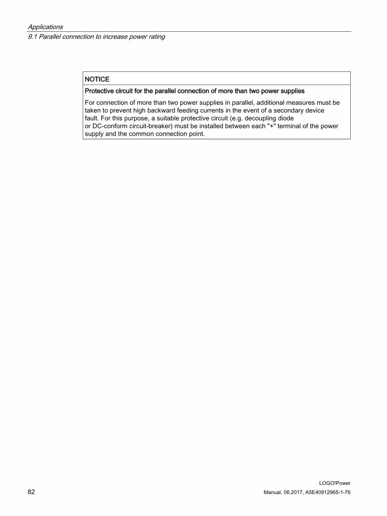
NOTICE
Protective circuit for the parallel connection of more than two power supplies
For connection of more than two power supplies in parallel, additional measures must be taken to prevent high backward feeding currents in the event of a secondary device fault. For this purpose, a suitable protective circuit (e.g. decoupling diode or DC-conform circuit-breaker) must be installed between each "+" terminal of the power supply and the common connection point.
Applications 9.2 Parallel connection for redundancy
LOGO!Power Manual, 06.2017, A5E40912965-1-76 83
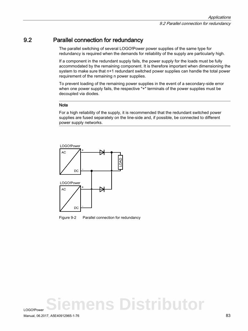
9.2 Parallel connection for redundancy The parallel switching of several LOGO!Power power supplies of the same type for redundancy is required when the demands for reliability of the supply are particularly high.
If a component in the redundant supply fails, the power supply for the loads must be fully accommodated by the remaining component. It is therefore important when dimensioning the system to make sure that n+1 redundant switched power supplies can handle the total power requirement of the remaining n power supplies.
To prevent loading of the remaining power supplies in the event of a secondary-side error when one power supply fails, the respective "+" terminals of the power supplies must be decoupled via diodes.
Note
For a high reliability of the supply, it is recommended that the redundant switched power supplies are fused separately on the line-side and, if possible, be connected to different power supply networks.
Figure 9-2 Parallel connection for redundancy
Siemens Distributor
Applications 9.3 Series connection for increased voltage
LOGO!Power 84 Manual, 06.2017, A5E40912965-1-76
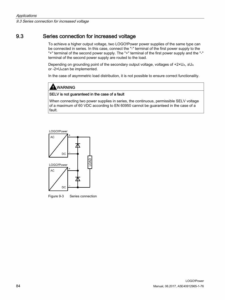
9.3 Series connection for increased voltage To achieve a higher output voltage, two LOGO!Power power supplies of the same type can be connected in series. In this case, connect the "-" terminal of the first power supply to the "+" terminal of the second power supply. The "+" terminal of the first power supply and the "-" terminal of the second power supply are routed to the load.
Depending on grounding point of the secondary output voltage, voltages of +2×UA, ±UA
or -2×UAcan be implemented.
In the case of asymmetric load distribution, it is not possible to ensure correct functionality.
WARNING
SELV is not guaranteed in the case of a fault
When connecting two power supplies in series, the continuous, permissible SELV voltage of a maximum of 60 VDC according to EN 60950 cannot be guaranteed in the case of a fault.
Figure 9-3 Series connection
Applications 9.4 Protection against short-time voltage dips
LOGO!Power Manual, 06.2017, A5E40912965-1-76 85
9.4 Protection against short-time voltage dips During a drop in the primary-side supply voltage, the LOGO!Power power supplies still maintain the output voltage over a short millisecond period (see Section Technical data (Page 55) Power failure buffering).
Siemens Distributor
Applications 9.4 Protection against short-time voltage dips
LOGO!Power 86 Manual, 06.2017, A5E40912965-1-76
LOGO!Power Manual, 06.2017, A5E40912965-1-76 87
Environment 10
The devices are in conformance with RoHS.
As a rule, only non-silicon precipitating materials are used.
Disposal guidelines Packaging and packaging aids can and should always be recycled. The product itself may not be disposed of as domestic refuse.
Siemens Distributor

Environment
LOGO!Power 88 Manual, 06.2017, A5E40912965-1-76
LOGO!Power Manual, 06.2017, A5E40912965-1-76 89
Service & Support 11
Technical support
Technical support for all IA/DT products can be accessed through the following communication channels:
● Telephone: + 49 (0) 911 895 7222
● Internet: Online support request form (http://www.siemens.de/automation/support-request)
Technical documentation on the Internet
Operating instructions and manuals for SITOP are available in the Internet: Operating instructions/manuals (http://www.siemens.com/sitop/manuals)
SITOP power supply homepage
General news about our power supplies is available in the Internet at the SITOP home page: SITOP (http://www.siemens.com/sitop)
Information material
SITOP information can be downloaded from the Internet: Information and download center (http://www.siemens.com/sitop-infomaterial)
CAx data
2D/3D data and circuit diagram macros can be downloaded from the Internet: Siemens image database (http://www.siemens.com/sitop-cax)
Request all CAx data via the CAx download manager: CAx shopping cart (http://www.siemens.com/cax)
SITOP Selection Tool
Simply and quickly select the optimum the power supply or DC-UPS: SITOP Selection Tool (http://www.siemens.com/sitop-selection-tool)
Online catalog and ordering system
The online catalog and the online ordering system are available through the Industry Mall homepage: Industry Mall (http://www.siemens.com/industrymall/de)
Siemens Distributor
Service & Support
LOGO!Power 90 Manual, 06.2017, A5E40912965-1-76
Contact persons
If you have any questions regarding the use of our products, then contact the Siemens contact person in your regional Siemens sales office.
You can find these addresses as follows:
● On the Internet (http://www.automation.siemens.com/partner)
● In Catalog CA 01