logicore ip ethernet statistics v3 - japan.xilinx.com · † chapter 9, quick start example design,...
TRANSCRIPT

LogiCORE IPEthernet Statistics v3.5
User Guide
UG170 March 1, 2011

Ethernet Statistics User Guide www.xilinx.com UG170 March 1, 2011
Xilinx is providing this product documentation, hereinafter “Information,” to you “AS IS” with no warranty of any kind, express or implied. Xilinx makes no representation that the Information, or any particular implementation thereof, is free from any claims of infringement. You are responsible for obtaining any rights you may require for any implementation based on the Information. All specifications are subject to change without notice.
XILINX EXPRESSLY DISCLAIMS ANY WARRANTY WHATSOEVER WITH RESPECT TO THE ADEQUACY OF THE INFORMATION OR ANY IMPLEMENTATION BASED THEREON, INCLUDING BUT NOT LIMITED TO ANY WARRANTIES OR REPRESENTATIONS THAT THIS IMPLEMENTATION IS FREE FROM CLAIMS OF INFRINGEMENT AND ANY IMPLIED WARRANTIES OF MERCHANTABILITY OR FITNESS FOR A PARTICULAR PURPOSE. Except as stated herein, none of the Information may be copied, reproduced, distributed, republished, downloaded, displayed, posted, or transmitted in any form or by any means including, but not limited to, electronic, mechanical, photocopying, recording, or otherwise, without the prior written consent of Xilinx.
© 2005-2011 Xilinx, Inc. XILINX, the Xilinx logo, Virtex, Spartan, ISE and other designated brands included herein are trademarks of Xilinx in the United States and other countries. The PowerPC name and logo are registered trademarks of IBM Corp. and used under license. All other trademarks are the property of their respective owners.
Revision History
This table shows the revision history for this document.
Date Version Revision
04/28/05 1.1 Initial Xilinx® product release.
01/18/06 1.2 Updated to Ethernet Statistics version 1.2, Xilinx tools v8.1i SP1.
07/13/06 1.3 Updated to Ethernet Statistics version 2.1, Xilinx tools v8.2i.
10/23/06 1.4 Updated to core v2.2, added support for Virtex®--5 LXT and Spartan®- 3-A FPGA families.
02/15/07 1.5 Updated to Ethernet Statistics version 2.3, Xilinx tools v9.1i.
08/08/07 1.6 Updated to Ethernet Statistics version 2.4, Xilinx tools v9.2i.
03/24/08 1.7 Updated to Ethernet Statistics version 2.5, Xilinx tools v10.1.
04/24/09 1.8 Updated to Ethernet Statistics version 3.1, Xilinx tools v11.1. Added support for Virtex-6 and Spartan-6 devices.
06/24/09 1.9 Updated to Ethernet Statistics version 3.2, Xilinx tools v11.2.
09/16/09 2.0 Updated to Ethernet Statistics version 3.3, Xilinx tools v11.3.
04/19/10 2.1 Updated to Ethernet Statistics version 3.4, Xilinx tools v12.1.
03/01/11 2.2 Updated to Ethernet Statistics version 3.5, Xilinx tools v13.1.

Ethernet Statistics User Guide www.xilinx.com 3UG170 March 1, 2011
Schedule of Figures . . . . . . . . . . . . . . . . . . . . . . . . . . . . . . . . . . . . . . . . . . . . . . . . . . . . . . . . . . 7
Schedule of Tables . . . . . . . . . . . . . . . . . . . . . . . . . . . . . . . . . . . . . . . . . . . . . . . . . . . . . . . . . . . 9
Preface: About This GuideGuide Contents . . . . . . . . . . . . . . . . . . . . . . . . . . . . . . . . . . . . . . . . . . . . . . . . . . . . . . . . . . . . . 11Additional Resources . . . . . . . . . . . . . . . . . . . . . . . . . . . . . . . . . . . . . . . . . . . . . . . . . . . . . . . 12Conventions . . . . . . . . . . . . . . . . . . . . . . . . . . . . . . . . . . . . . . . . . . . . . . . . . . . . . . . . . . . . . . . . 12
Typographical . . . . . . . . . . . . . . . . . . . . . . . . . . . . . . . . . . . . . . . . . . . . . . . . . . . . . . . . . . . . 12Online Document . . . . . . . . . . . . . . . . . . . . . . . . . . . . . . . . . . . . . . . . . . . . . . . . . . . . . . . . . 13List of Acronyms . . . . . . . . . . . . . . . . . . . . . . . . . . . . . . . . . . . . . . . . . . . . . . . . . . . . . . . . . 14
Chapter 1: IntroductionSystem Requirements . . . . . . . . . . . . . . . . . . . . . . . . . . . . . . . . . . . . . . . . . . . . . . . . . . . . . . . 15About the Core . . . . . . . . . . . . . . . . . . . . . . . . . . . . . . . . . . . . . . . . . . . . . . . . . . . . . . . . . . . . . . 15Licensing Information. . . . . . . . . . . . . . . . . . . . . . . . . . . . . . . . . . . . . . . . . . . . . . . . . . . . . . . 16Recommended Design Experience . . . . . . . . . . . . . . . . . . . . . . . . . . . . . . . . . . . . . . . . . . . 16Additional Core Resources . . . . . . . . . . . . . . . . . . . . . . . . . . . . . . . . . . . . . . . . . . . . . . . . . . 16Technical Support. . . . . . . . . . . . . . . . . . . . . . . . . . . . . . . . . . . . . . . . . . . . . . . . . . . . . . . . . . . 16Feedback. . . . . . . . . . . . . . . . . . . . . . . . . . . . . . . . . . . . . . . . . . . . . . . . . . . . . . . . . . . . . . . . . . . . 17
Ethernet Statistics Core . . . . . . . . . . . . . . . . . . . . . . . . . . . . . . . . . . . . . . . . . . . . . . . . . . . . 17Document . . . . . . . . . . . . . . . . . . . . . . . . . . . . . . . . . . . . . . . . . . . . . . . . . . . . . . . . . . . . . . . 17
Chapter 2: Generating the CoreGraphical User Interface . . . . . . . . . . . . . . . . . . . . . . . . . . . . . . . . . . . . . . . . . . . . . . . . . . . . 19
Component Name . . . . . . . . . . . . . . . . . . . . . . . . . . . . . . . . . . . . . . . . . . . . . . . . . . . . . . . . 19MAC Type . . . . . . . . . . . . . . . . . . . . . . . . . . . . . . . . . . . . . . . . . . . . . . . . . . . . . . . . . . . . . . . 20Number of Statistics. . . . . . . . . . . . . . . . . . . . . . . . . . . . . . . . . . . . . . . . . . . . . . . . . . . . . . . 20Statistics Width . . . . . . . . . . . . . . . . . . . . . . . . . . . . . . . . . . . . . . . . . . . . . . . . . . . . . . . . . . . 20Statistics Clear on Reset. . . . . . . . . . . . . . . . . . . . . . . . . . . . . . . . . . . . . . . . . . . . . . . . . . . . 20
Parameter Values in the XCO File . . . . . . . . . . . . . . . . . . . . . . . . . . . . . . . . . . . . . . . . . . . 21Output Generation . . . . . . . . . . . . . . . . . . . . . . . . . . . . . . . . . . . . . . . . . . . . . . . . . . . . . . . . . . 21
Chapter 3: Designing with the CoreThe Ethernet Statistics Core and Example Design . . . . . . . . . . . . . . . . . . . . . . . . . . . . 23
Example Design . . . . . . . . . . . . . . . . . . . . . . . . . . . . . . . . . . . . . . . . . . . . . . . . . . . . . . . . . . 24Statistics Core . . . . . . . . . . . . . . . . . . . . . . . . . . . . . . . . . . . . . . . . . . . . . . . . . . . . . . . . . . . . 24
Implementing the Ethernet Statistics . . . . . . . . . . . . . . . . . . . . . . . . . . . . . . . . . . . . . . . . 24Design Steps . . . . . . . . . . . . . . . . . . . . . . . . . . . . . . . . . . . . . . . . . . . . . . . . . . . . . . . . . . . . . 24Keep it Registered . . . . . . . . . . . . . . . . . . . . . . . . . . . . . . . . . . . . . . . . . . . . . . . . . . . . . . . . 25Recognize Timing Critical Signals . . . . . . . . . . . . . . . . . . . . . . . . . . . . . . . . . . . . . . . . . . . 25Use Supported Design Flows . . . . . . . . . . . . . . . . . . . . . . . . . . . . . . . . . . . . . . . . . . . . . . . 25
Table of Contents

4 www.xilinx.com Ethernet Statistics User GuideUG170 March 1, 2011
Chapter 4: Core ArchitectureOverview . . . . . . . . . . . . . . . . . . . . . . . . . . . . . . . . . . . . . . . . . . . . . . . . . . . . . . . . . . . . . . . . . . . 27Core Interfaces . . . . . . . . . . . . . . . . . . . . . . . . . . . . . . . . . . . . . . . . . . . . . . . . . . . . . . . . . . . . . . 28Increment Interface . . . . . . . . . . . . . . . . . . . . . . . . . . . . . . . . . . . . . . . . . . . . . . . . . . . . . . . . . 29
Increment Interface Overview . . . . . . . . . . . . . . . . . . . . . . . . . . . . . . . . . . . . . . . . . . . . . . 29Low-Frequency Statistical Counters . . . . . . . . . . . . . . . . . . . . . . . . . . . . . . . . . . . . . . . . . 30
Bandwidth Requirements . . . . . . . . . . . . . . . . . . . . . . . . . . . . . . . . . . . . . . . . . . . . . . . . 30Cheating the Bandwidth Requirements to Provide Extra Statistics Counters. . . . . . . . . 31
High-Frequency Statistical Counters . . . . . . . . . . . . . . . . . . . . . . . . . . . . . . . . . . . . . . . . 32Counter 0 . . . . . . . . . . . . . . . . . . . . . . . . . . . . . . . . . . . . . . . . . . . . . . . . . . . . . . . . . . . . 32Counter 1 . . . . . . . . . . . . . . . . . . . . . . . . . . . . . . . . . . . . . . . . . . . . . . . . . . . . . . . . . . . . 32Counter 2 . . . . . . . . . . . . . . . . . . . . . . . . . . . . . . . . . . . . . . . . . . . . . . . . . . . . . . . . . . . . 33Counter 3 . . . . . . . . . . . . . . . . . . . . . . . . . . . . . . . . . . . . . . . . . . . . . . . . . . . . . . . . . . . . 33
Summary of the Increment Interface. . . . . . . . . . . . . . . . . . . . . . . . . . . . . . . . . . . . . . . . . 34High-Frequency Statistical Counters . . . . . . . . . . . . . . . . . . . . . . . . . . . . . . . . . . . . . . . 34Low-Frequency Statistical Counters . . . . . . . . . . . . . . . . . . . . . . . . . . . . . . . . . . . . . . . . 34
Counter Reset Functionality . . . . . . . . . . . . . . . . . . . . . . . . . . . . . . . . . . . . . . . . . . . . . . . . . 35Core Reference Clock and Reset . . . . . . . . . . . . . . . . . . . . . . . . . . . . . . . . . . . . . . . . . . . . . 35
REF_CLK Frequency . . . . . . . . . . . . . . . . . . . . . . . . . . . . . . . . . . . . . . . . . . . . . . . . . . . . . . 35Example 1 . . . . . . . . . . . . . . . . . . . . . . . . . . . . . . . . . . . . . . . . . . . . . . . . . . . . . . . . . . . . 36Example 2 . . . . . . . . . . . . . . . . . . . . . . . . . . . . . . . . . . . . . . . . . . . . . . . . . . . . . . . . . . . . 36
Management Interface . . . . . . . . . . . . . . . . . . . . . . . . . . . . . . . . . . . . . . . . . . . . . . . . . . . . . . 37HOST_CLK Frequency . . . . . . . . . . . . . . . . . . . . . . . . . . . . . . . . . . . . . . . . . . . . . . . . . . . . 38The Management Read Transaction . . . . . . . . . . . . . . . . . . . . . . . . . . . . . . . . . . . . . . . . . 38
Chapter 5: Example Design Statistics CountersExample Design . . . . . . . . . . . . . . . . . . . . . . . . . . . . . . . . . . . . . . . . . . . . . . . . . . . . . . . . . . . . . 41Example Design Statistics . . . . . . . . . . . . . . . . . . . . . . . . . . . . . . . . . . . . . . . . . . . . . . . . . . . 42
High-Frequency Statistical Counters . . . . . . . . . . . . . . . . . . . . . . . . . . . . . . . . . . . . . . . . 42Low-Frequency Statistical Counters . . . . . . . . . . . . . . . . . . . . . . . . . . . . . . . . . . . . . . . . . 43
Modifying the Example Design. . . . . . . . . . . . . . . . . . . . . . . . . . . . . . . . . . . . . . . . . . . . . . 46Example Counter Modification . . . . . . . . . . . . . . . . . . . . . . . . . . . . . . . . . . . . . . . . . . . . . 46
VHDL . . . . . . . . . . . . . . . . . . . . . . . . . . . . . . . . . . . . . . . . . . . . . . . . . . . . . . . . . . . . . . . 47Verilog . . . . . . . . . . . . . . . . . . . . . . . . . . . . . . . . . . . . . . . . . . . . . . . . . . . . . . . . . . . . . . 48
Chapter 6: Constraining the CoreRequired Constraints. . . . . . . . . . . . . . . . . . . . . . . . . . . . . . . . . . . . . . . . . . . . . . . . . . . . . . . . 49
Device, Package, and Speed Grade Selection . . . . . . . . . . . . . . . . . . . . . . . . . . . . . . . . . 49I/O Location Constraints . . . . . . . . . . . . . . . . . . . . . . . . . . . . . . . . . . . . . . . . . . . . . . . . . . 49Placement Constraints . . . . . . . . . . . . . . . . . . . . . . . . . . . . . . . . . . . . . . . . . . . . . . . . . . . . . 49Timing Constraints . . . . . . . . . . . . . . . . . . . . . . . . . . . . . . . . . . . . . . . . . . . . . . . . . . . . . . . 49
PERIOD Constraints for Clock Nets . . . . . . . . . . . . . . . . . . . . . . . . . . . . . . . . . . . . . . . . 50Timespecs for Critical Logic within the Core . . . . . . . . . . . . . . . . . . . . . . . . . . . . . . . . . 51IO Constraints. . . . . . . . . . . . . . . . . . . . . . . . . . . . . . . . . . . . . . . . . . . . . . . . . . . . . . . . . 52

Ethernet Statistics User Guide www.xilinx.com 5UG170 March 1, 2011
Chapter 7: Implementing the DesignPre-implementation Simulation . . . . . . . . . . . . . . . . . . . . . . . . . . . . . . . . . . . . . . . . . . . . . 53
Using the Simulation Model . . . . . . . . . . . . . . . . . . . . . . . . . . . . . . . . . . . . . . . . . . . . . . . . 53Synthesis . . . . . . . . . . . . . . . . . . . . . . . . . . . . . . . . . . . . . . . . . . . . . . . . . . . . . . . . . . . . . . . . . . . 54
XST - VHDL . . . . . . . . . . . . . . . . . . . . . . . . . . . . . . . . . . . . . . . . . . . . . . . . . . . . . . . . . . . . . 54XST - Verilog . . . . . . . . . . . . . . . . . . . . . . . . . . . . . . . . . . . . . . . . . . . . . . . . . . . . . . . . . . . . . 54
Implementation . . . . . . . . . . . . . . . . . . . . . . . . . . . . . . . . . . . . . . . . . . . . . . . . . . . . . . . . . . . . . 55Generating the Xilinx Netlist . . . . . . . . . . . . . . . . . . . . . . . . . . . . . . . . . . . . . . . . . . . . . . . 55Mapping the Design . . . . . . . . . . . . . . . . . . . . . . . . . . . . . . . . . . . . . . . . . . . . . . . . . . . . . . 55Placing and Routing the Design . . . . . . . . . . . . . . . . . . . . . . . . . . . . . . . . . . . . . . . . . . . . 55Static Timing Analysis . . . . . . . . . . . . . . . . . . . . . . . . . . . . . . . . . . . . . . . . . . . . . . . . . . . . . 55Generating a Bitstream . . . . . . . . . . . . . . . . . . . . . . . . . . . . . . . . . . . . . . . . . . . . . . . . . . . . 55
Post-Implementation Simulation . . . . . . . . . . . . . . . . . . . . . . . . . . . . . . . . . . . . . . . . . . . . 56Generating a Simulation Model . . . . . . . . . . . . . . . . . . . . . . . . . . . . . . . . . . . . . . . . . . . . . 56Using the Model . . . . . . . . . . . . . . . . . . . . . . . . . . . . . . . . . . . . . . . . . . . . . . . . . . . . . . . . . . 56
Other Implementation Information . . . . . . . . . . . . . . . . . . . . . . . . . . . . . . . . . . . . . . . . . . 56
Chapter 8: Interfacing to Xilinx Ethernet MAC CoresIntegrating with the Virtex-6 FPGA Embedded Tri-Mode Ethernet MAC . . . . . 57Integrating with the Virtex-5 FPGA Embedded Tri-Mode Ethernet MAC . . . . . 59Integrating with Virtex-4 FPGA Embedded Tri-Mode Ethernet MAC. . . . . . . . . 61Integrating with Tri-Mode Ethernet MAC Solution . . . . . . . . . . . . . . . . . . . . . . . . . . 63Sharing the Management Interface . . . . . . . . . . . . . . . . . . . . . . . . . . . . . . . . . . . . . . . . . . 65
VHDL Example . . . . . . . . . . . . . . . . . . . . . . . . . . . . . . . . . . . . . . . . . . . . . . . . . . . . . . . . . . 65Verilog Example . . . . . . . . . . . . . . . . . . . . . . . . . . . . . . . . . . . . . . . . . . . . . . . . . . . . . . . . . . 65
Chapter 9: Quick Start Example DesignOverview . . . . . . . . . . . . . . . . . . . . . . . . . . . . . . . . . . . . . . . . . . . . . . . . . . . . . . . . . . . . . . . . . . . 67Generating the Core . . . . . . . . . . . . . . . . . . . . . . . . . . . . . . . . . . . . . . . . . . . . . . . . . . . . . . . . . 69Implementing the Example Design . . . . . . . . . . . . . . . . . . . . . . . . . . . . . . . . . . . . . . . . . . 71Simulating the Example Design . . . . . . . . . . . . . . . . . . . . . . . . . . . . . . . . . . . . . . . . . . . . . 72
Setting up for Simulation . . . . . . . . . . . . . . . . . . . . . . . . . . . . . . . . . . . . . . . . . . . . . . . . . . 72Functional Simulation . . . . . . . . . . . . . . . . . . . . . . . . . . . . . . . . . . . . . . . . . . . . . . . . . . . . . 72Timing Simulation . . . . . . . . . . . . . . . . . . . . . . . . . . . . . . . . . . . . . . . . . . . . . . . . . . . . . . . . 72
What’s Next? . . . . . . . . . . . . . . . . . . . . . . . . . . . . . . . . . . . . . . . . . . . . . . . . . . . . . . . . . . . . . . . . 73
Chapter 10: Detailed Example DesignDirectory Structure and File Descriptions . . . . . . . . . . . . . . . . . . . . . . . . . . . . . . . . . . . . 75Directory and File Contents . . . . . . . . . . . . . . . . . . . . . . . . . . . . . . . . . . . . . . . . . . . . . . . . . 76
<project directory> . . . . . . . . . . . . . . . . . . . . . . . . . . . . . . . . . . . . . . . . . . . . . . . . . . . . . . . 76<project directory>/<component name> . . . . . . . . . . . . . . . . . . . . . . . . . . . . . . . . . . . . 76<component name>/doc . . . . . . . . . . . . . . . . . . . . . . . . . . . . . . . . . . . . . . . . . . . . . . . . . . 77<component name>/example_design . . . . . . . . . . . . . . . . . . . . . . . . . . . . . . . . . . . . . . . 77<component name>/implement . . . . . . . . . . . . . . . . . . . . . . . . . . . . . . . . . . . . . . . . . . . . 78implement/results . . . . . . . . . . . . . . . . . . . . . . . . . . . . . . . . . . . . . . . . . . . . . . . . . . . . . . . . 78<component name>/simulation . . . . . . . . . . . . . . . . . . . . . . . . . . . . . . . . . . . . . . . . . . . . 78simulation/functional . . . . . . . . . . . . . . . . . . . . . . . . . . . . . . . . . . . . . . . . . . . . . . . . . . . . . 79simulation/timing . . . . . . . . . . . . . . . . . . . . . . . . . . . . . . . . . . . . . . . . . . . . . . . . . . . . . . . . 79

6 www.xilinx.com Ethernet Statistics User GuideUG170 March 1, 2011
Implementation Scripts . . . . . . . . . . . . . . . . . . . . . . . . . . . . . . . . . . . . . . . . . . . . . . . . . . . . . 80Simulation Scripts . . . . . . . . . . . . . . . . . . . . . . . . . . . . . . . . . . . . . . . . . . . . . . . . . . . . . . . . . . 81
Functional Simulation . . . . . . . . . . . . . . . . . . . . . . . . . . . . . . . . . . . . . . . . . . . . . . . . . . . . . 81Timing Simulation . . . . . . . . . . . . . . . . . . . . . . . . . . . . . . . . . . . . . . . . . . . . . . . . . . . . . . . . 81
Example Design . . . . . . . . . . . . . . . . . . . . . . . . . . . . . . . . . . . . . . . . . . . . . . . . . . . . . . . . . . . . . 81Top Level Example Design . . . . . . . . . . . . . . . . . . . . . . . . . . . . . . . . . . . . . . . . . . . . . . . . . 81Block Level . . . . . . . . . . . . . . . . . . . . . . . . . . . . . . . . . . . . . . . . . . . . . . . . . . . . . . . . . . . . . . 82Vector Decoder . . . . . . . . . . . . . . . . . . . . . . . . . . . . . . . . . . . . . . . . . . . . . . . . . . . . . . . . . . . 83
Demonstration Test Bench . . . . . . . . . . . . . . . . . . . . . . . . . . . . . . . . . . . . . . . . . . . . . . . . . . 83Customizing the Test Bench . . . . . . . . . . . . . . . . . . . . . . . . . . . . . . . . . . . . . . . . . . . . . . . . 85
Appendix A: Relating the Statistics Counters to Statistical Specifications
IEEE 802.3-2008 Clause 30 . . . . . . . . . . . . . . . . . . . . . . . . . . . . . . . . . . . . . . . . . . . . . . . . . . . 88RFC1643 . . . . . . . . . . . . . . . . . . . . . . . . . . . . . . . . . . . . . . . . . . . . . . . . . . . . . . . . . . . . . . . . . . . . 91RFC1757 (EtherStats) . . . . . . . . . . . . . . . . . . . . . . . . . . . . . . . . . . . . . . . . . . . . . . . . . . . . . . . . 93

Ethernet Statistics User Guide www.xilinx.com 7UG170 March 1, 2011
Chapter 1: Introduction
Chapter 2: Generating the CoreFigure 2-1: Main Screen. . . . . . . . . . . . . . . . . . . . . . . . . . . . . . . . . . . . . . . . . . . . . . . . . . . . . . . . 19
Chapter 3: Designing with the CoreFigure 3-1: Ethernet Statistics Example Design . . . . . . . . . . . . . . . . . . . . . . . . . . . . . . . . . . . 23
Chapter 4: Core ArchitectureFigure 4-1: Ethernet Statistics Top-Level Block Diagram. . . . . . . . . . . . . . . . . . . . . . . . . . . 27Figure 4-2: Component Pinout . . . . . . . . . . . . . . . . . . . . . . . . . . . . . . . . . . . . . . . . . . . . . . . . . . 28Figure 4-3: Increment Vector Timing Diagram . . . . . . . . . . . . . . . . . . . . . . . . . . . . . . . . . . . 30Figure 4-4: Counter 0 Timing Diagram . . . . . . . . . . . . . . . . . . . . . . . . . . . . . . . . . . . . . . . . . . 32Figure 4-5: Counter 1 Timing Diagram . . . . . . . . . . . . . . . . . . . . . . . . . . . . . . . . . . . . . . . . . . 32Figure 4-6: Counter 2 Timing Diagram . . . . . . . . . . . . . . . . . . . . . . . . . . . . . . . . . . . . . . . . . . 33Figure 4-7: Counter 3 Timing Diagram . . . . . . . . . . . . . . . . . . . . . . . . . . . . . . . . . . . . . . . . . . 33Figure 4-8: Statistical Counter Read Transaction . . . . . . . . . . . . . . . . . . . . . . . . . . . . . . . . . . 38
Chapter 5: Example Design Statistics CountersFigure 5-1: Ethernet Statistics Example Design . . . . . . . . . . . . . . . . . . . . . . . . . . . . . . . . . . . 41
Chapter 6: Constraining the Core
Chapter 7: Implementing the Design
Chapter 8: Interfacing to Xilinx Ethernet MAC CoresFigure 8-1: Integrating to a Single Instance of the
Virtex-6 FPGA Embedded Tri-Mode Ethernet MAC . . . . . . . . . . . . . . . . . . . . . . . . . . . . 58Figure 8-2: Integrating to a Single Instance of the
Virtex-5 FPGA Embedded Tri-Mode Ethernet MAC . . . . . . . . . . . . . . . . . . . . . . . . . . . . 60Figure 8-3: Integrating to a Single Instance of the
Virtex-4 FPGA Embedded Tri-Mode Ethernet MAC . . . . . . . . . . . . . . . . . . . . . . . . . . . . 62Figure 8-4: Integrating to the Tri-Mode Ethernet MAC Solution . . . . . . . . . . . . . . . . . . . . 64
Chapter 9: Quick Start Example DesignFigure 9-1: Ethernet Statistics Example Design and Test Bench. . . . . . . . . . . . . . . . . . . . . 68Figure 9-2: Project Options . . . . . . . . . . . . . . . . . . . . . . . . . . . . . . . . . . . . . . . . . . . . . . . . . . . . . 69Figure 9-3: Project Generation Options . . . . . . . . . . . . . . . . . . . . . . . . . . . . . . . . . . . . . . . . . . 70Figure 9-4: Customization Screen . . . . . . . . . . . . . . . . . . . . . . . . . . . . . . . . . . . . . . . . . . . . . . . 71
Schedule of Figures

8 www.xilinx.com Ethernet Statistics User GuideUG170 March 1, 2011
Chapter 10: Detailed Example DesignFigure 10-1: Example Design Top-Level HDL for Ethernet Statistics Core . . . . . . . . . . . 82Figure 10-2: Demonstration Test Bench for
Ethernet Statistics Core and Example Design . . . . . . . . . . . . . . . . . . . . . . . . . . . . . . . . . . 83
Appendix A: Relating the Statistics Counters to Statistical Specifications

Ethernet Statistics User Guide www.xilinx.com 9UG170 March 1, 2011
Chapter 1: Introduction
Chapter 2: Generating the CoreTable 2-1: XCO File Values and Default Values. . . . . . . . . . . . . . . . . . . . . . . . . . . . . . . . . . . 21
Chapter 3: Designing with the Core
Chapter 4: Core ArchitectureTable 4-1: Increment Interface Signals . . . . . . . . . . . . . . . . . . . . . . . . . . . . . . . . . . . . . . . . . . . 29Table 4-2: Summary of High-Frequency Statistical Counters . . . . . . . . . . . . . . . . . . . . . . . 34Table 4-3: Summary of Low-Frequency Statistical Counters . . . . . . . . . . . . . . . . . . . . . . . . 34Table 4-4: Reference Clock and Reset Signals . . . . . . . . . . . . . . . . . . . . . . . . . . . . . . . . . . . . 35Table 4-5: Management Interface Signals . . . . . . . . . . . . . . . . . . . . . . . . . . . . . . . . . . . . . . . . 37
Chapter 5: Example Design Statistics CountersTable 5-1: Example Design Statistics Counters 0 to 3 . . . . . . . . . . . . . . . . . . . . . . . . . . . . . . 42Table 5-2: Example Design Statistics Counters 4 to 10 . . . . . . . . . . . . . . . . . . . . . . . . . . . . . 43Table 5-3: Example Design Statistics Counters 11 to 17 . . . . . . . . . . . . . . . . . . . . . . . . . . . . 43Table 5-4: Example Design Statistics Counters 18 Upwards . . . . . . . . . . . . . . . . . . . . . . . . 44
Chapter 6: Constraining the Core
Chapter 7: Implementing the Design
Chapter 8: Interfacing to Xilinx Ethernet MAC Cores
Chapter 9: Quick Start Example Design
Chapter 10: Detailed Example DesignTable 10-1: Project Directory. . . . . . . . . . . . . . . . . . . . . . . . . . . . . . . . . . . . . . . . . . . . . . . . . . . . 76Table 10-2: Component Name Directory . . . . . . . . . . . . . . . . . . . . . . . . . . . . . . . . . . . . . . . . . 76Table 10-3: Doc Directory . . . . . . . . . . . . . . . . . . . . . . . . . . . . . . . . . . . . . . . . . . . . . . . . . . . . . . 77Table 10-4: Example Design Directory . . . . . . . . . . . . . . . . . . . . . . . . . . . . . . . . . . . . . . . . . . . 77Table 10-5: Implement Directory . . . . . . . . . . . . . . . . . . . . . . . . . . . . . . . . . . . . . . . . . . . . . . . . 78Table 10-6: Results Directory . . . . . . . . . . . . . . . . . . . . . . . . . . . . . . . . . . . . . . . . . . . . . . . . . . . 78Table 10-7: Simulation Directory . . . . . . . . . . . . . . . . . . . . . . . . . . . . . . . . . . . . . . . . . . . . . . . . 78Table 10-8: Functional Directory . . . . . . . . . . . . . . . . . . . . . . . . . . . . . . . . . . . . . . . . . . . . . . . . 79Table 10-9: Functional Directory . . . . . . . . . . . . . . . . . . . . . . . . . . . . . . . . . . . . . . . . . . . . . . . . 79
Schedule of Tables

10 www.xilinx.com Ethernet Statistics User GuideUG170 March 1, 2011
Appendix A: Relating the Statistics Counters to Statistical Specifications
Table A-1: Example Design Defined Statistics Counters Compared with IEEE 802.3 Clause 30 . . . . . . . . . . . . . . . . . . . . . . . . . . . . . . . . . . . . . . . . . . . . . . . . . . . . . . . 88
Table A-2: Example Design Defined Statistics Counters Compared with RFC1643 . . . . 91Table A-3: Example Design Defined Statistics Counters Compared with
RFC1757 (EtherStats) . . . . . . . . . . . . . . . . . . . . . . . . . . . . . . . . . . . . . . . . . . . . . . . . . . . . . . . . 93
Ethernet Statistics User Guide www.xilinx.com 11UG170 March 1, 2011
Preface
About This Guide
The Ethernet Statistics v3.5 User Guide describes the function and operation of the Xilinx® Ethernet Statistics core, including information about designing, customizing, and implementing the core.
Guide ContentsThis guide contains these chapters and an appendix:
• Preface, About this Guide, introduces the organization and purpose of the User Guide and the conventions used in this document.
• Chapter 1, Introduction, describes the core and related information, including recommended design experience, additional resources, technical support, and submitting feedback to Xilinx.
• Chapter 2, Generating the Core, describes the graphical user interface (GUI) options used to generate and customize the core.
• Chapter 3, Designing with the Core, introduces the steps required to turn an Ethernet Statistics core into a fully functioning design integrated with user application logic.
• Chapter 4, Core Architecture, defines the interfaces to the Ethernet Statistics core NGC netlist and describes how to use the core in specific applications.
• Chapter 5, Example Design Statistics Counters, defines the statistics counters implemented by the example design and introduces the concept of modifying the example design to implement alternative statistical counters.
• Chapter 6, Constraining the Core, defines the constraint requirements of the Ethernet Statistics core.
• Chapter 7, Implementing the Design, describes how to simulate and implement your design containing the Ethernet Statistics core.
• Chapter 8, Interfacing to Xilinx Ethernet MAC Cores, defines additional design considerations associated with implementing the Ethernet Statistics core with other supported Xilinx Ethernet MAC cores.
• Chapter 9, Quick Start Example Design, provides instructions to quickly generate the core and run the example design through implementation and simulation using the default settings.
• Chapter 10, Detailed Example Design, describes the demonstration test bench in detail and provides directions for how to customize the demonstration test bench for use in an application.
• Appendix A, Relating the Statistics Counters to Statistical Specifications, defines the contrasting relationship between the counters implemented in the example design and the counters defined in the IEEE 802.3 clause 30, RFC1643, and RFC1757 (EtherStats) specifications.

12 www.xilinx.com Ethernet Statistics User GuideUG170 March 1, 2011
Preface: About This Guide
Additional ResourcesTo find additional documentation, see the Xilinx website at:
www.xilinx.com/support/documentation/index.htm.
To search the Answer Database of silicon, software, and IP questions and answers, or to create a technical support WebCase, see the Xilinx website at:
www.xilinx.com/support
ConventionsThis document uses the following conventions. An example illustrates each convention.
TypographicalThese typographical conventions are used in this document:
Convention Meaning or Use Example
Courier font
Messages, prompts, and program files that the system displays. Signal names in text also.
speed grade: - 100
Courier boldLiteral commands that you enter in a syntactical statement
ngdbuild design_name
Helvetica bold
Commands that you select from a menu
File ∅ Open
Keyboard shortcuts Ctrl+C
Italic font
Variables in a syntax statement for which you must supply values
ngdbuild design_name
References to other manuals See the User Guide for details.
Emphasis in textIf a wire is drawn so that it overlaps the pin of a symbol, the two nets are not connected.
Dark ShadingItems that are not supported or reserved
This feature is not supported
Square brackets [ ]
An optional entry or parameter. However, in bus specifications, such as bus[7:0], they are required.
ngdbuild [option_name] design_name
Braces { }A list of items from which you must choose one or more lowpwr ={on|off}
Vertical bar |Separates items in a list of choices lowpwr ={on|off}
Angle brackets < >User-defined variable or in code samples <directory name>
Ethernet Statistics User Guide www.xilinx.com 13UG170 March 1, 2011
Conventions
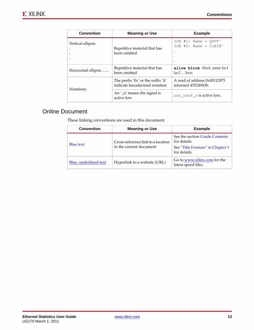
Online DocumentThese linking conventions are used in this document:
Vertical ellipsis...
Repetitive material that has been omitted
IOB #1: Name = QOUT’ IOB #2: Name = CLKIN’...
Horizontal ellipsis . . .Repetitive material that has been omitted
allow block block_name loc1 loc2 ... locn;
Notations
The prefix ‘0x’ or the suffix ‘h’ indicate hexadecimal notation
A read of address 0x00112975 returned 45524943h.
An ‘_n’ means the signal is active low
usr_teof_n is active low.
Convention Meaning or Use Example
Convention Meaning or Use Example
Blue text Cross-reference link to a location in the current document
See the section Guide Contents for details.
See “Title Formats” in Chapter 1 for details.
Blue, underlined text Hyperlink to a website (URL)Go to www.xilinx.com for the latest speed files.

14 www.xilinx.com Ethernet Statistics User GuideUG170 March 1, 2011
Preface: About This Guide
List of AcronymsThis table describes acronyms used in this manual.
Acronym Spelled Out
FPGA Field Programmable Gate Array
HDL Hardware Description Language
IES Incisive Enterprise Simulator
IOB Input/Output Block
IP Intellectual Property
ISE® Integrated Software Environment
MAC Media Access Controller
MDIO Management Data Input/Output
NGC Native Generic Circuit
UCF User Constraint File
VHDL VHSIC Hardware Description Language (VHSIC an acronym for Very High-Speed Integrated Circuits)
VLAN Virtual LAN (Local Area Network)
XST Xilinx Synthesis Technology

Ethernet Statistics User Guide www.xilinx.com 15UG170 March 1, 2011
Chapter 1
Introduction
This chapter introduces the Ethernet Statistics core and provides related information, including recommended design experience, additional resources, technical support, and submitting feedback to Xilinx. The Ethernet Statistics core provides a user configurable collection of statistical counters that can be used to gather network traffic statistics for Xilinx® Ethernet Media Access Controller (MAC) products. The core supports both the Verilog and VHDL design environments—in addition, the example design delivered with the core is provided in Verilog and VHDL.
System RequirementsWindows
• Windows XP Professional 32-bit/64-bit
• Windows Vista Business 32-bit/64-bit
Linux
• Red Hat Enterprise Linux WS v4.0 32-bit/64-bit
• Red Hat Enterprise Desktop v5.0 32-bit/64-bit (with Workstation Option)
• SUSE Linux Enterprise (SLE) desktop and server v10.1 32-bit/64-bit
Software
• ISE® v13.1 software
About the CoreThe Ethernet Statistics core is a Xilinx CORE Generator™ IP software core, included in the latest IP update on the Xilinx IP Center. For detailed information about the core, see www.xilinx.com/products/ipcenter/ETHERNET_STATS.htm. For details about licensing options, see the next section, Licensing Information.

16 www.xilinx.com Ethernet Statistics User GuideUG170 March 1, 2011
Chapter 1: Introduction
Licensing InformationThe Ethernet Statistics core is provided under the End User License Agreement and can begenerated using the Xilinx CORE Generator system v13.1 or higher. The CORE Generatorsystem is shipped with Xilinx ISE Design Suite Series Development software.
In ISE v13.1 software and later, a license key is not required to access the IP. To access thewrapper in ISE v12.4 software and older, a no cost full license must be obtained fromXilinx. See the Ethernet Statistics product page. Please see the version of the getting startedguide for the version of the core you are using for installation information.
Contact your local Xilinx sales representative for pricing and availability of other XilinxLogiCORE IP modules and software. Information on additional LogiCORE IP modules isavailable at the Xilinx IP Center.
Recommended Design ExperienceAlthough the Ethernet Statistics core is a fully-verified solution, the challenge associated with implementing a complete design varies depending on the configuration and functionality of the application. For best results, previous experience building high-performance, pipelined FPGA designs using Xilinx implementation software and user constraints files (UCF) is recommended. Contact your local Xilinx representative for a closer review and estimation of your specific requirements.
Additional Core ResourcesFor detailed information and updates about the Ethernet Statistics core, see the related documents, located on the Ethernet Statistics product page at: www.xilinx.com/products/ipcenter/ETHERNET_STATS.htm.
• Ethernet Statistics Data Sheet
• Ethernet Statistics Release Notes
For updates to this guide, see the Ethernet Statistics User Guide, also located on the Ethernet Statistics product page.
Technical SupportFor technical support, go to www.xilinx.com/support. Questions are routed to a team of engineers with expertise using the Ethernet Statistics core.
Xilinx provides technical support for use of this product as described in this guide. Xilinx cannot guarantee timing, functionality, or support of this product for designs that do not follow these guidelines.

Ethernet Statistics User Guide www.xilinx.com 17UG170 March 1, 2011
Feedback
FeedbackXilinx welcomes comments and suggestions about the Ethernet Statistics core and the accompanying documentation.
Ethernet Statistics CoreFor comments or suggestions about the Ethernet Statistics core, submit a webcase from www.xilinx.com/support. Be sure to include this information:
• Product name
• Core version number
• Explanation of your comments
DocumentFor comments or suggestions about this document, submit a webcase from www.xilinx.com/support. Be sure to include this information:
• Document title
• Document number
• Page number(s) to which your comments refer
• Explanation of your comments

18 www.xilinx.com Ethernet Statistics User GuideUG170 March 1, 2011
Chapter 1: Introduction
Ethernet Statistics User Guide www.xilinx.com 19UG170 March 1, 2011
Chapter 2
Generating the Core
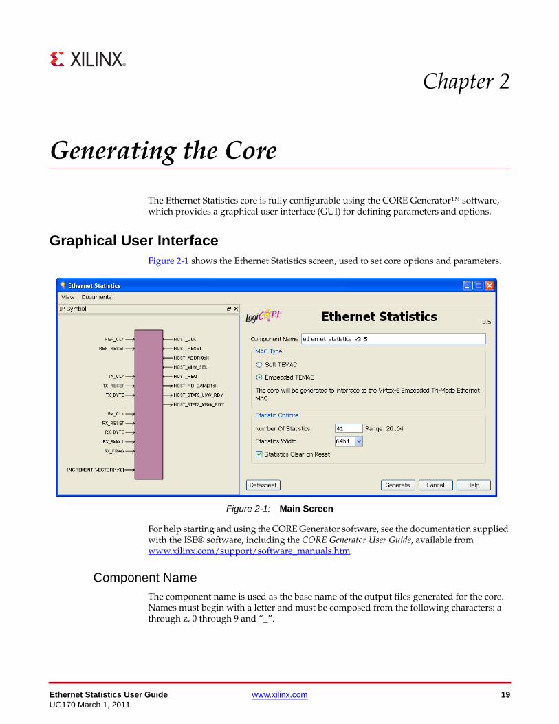
The Ethernet Statistics core is fully configurable using the CORE Generator™ software, which provides a graphical user interface (GUI) for defining parameters and options.
Graphical User InterfaceFigure 2-1 shows the Ethernet Statistics screen, used to set core options and parameters.
For help starting and using the CORE Generator software, see the documentation supplied with the ISE® software, including the CORE Generator User Guide, available from www.xilinx.com/support/software_manuals.htm
Component NameThe component name is used as the base name of the output files generated for the core. Names must begin with a letter and must be composed from the following characters: a through z, 0 through 9 and “_”.
X-Ref Target - Figure 2-1
Figure 2-1: Main Screen

20 www.xilinx.com Ethernet Statistics User GuideUG170 March 1, 2011
Chapter 2: Generating the Core
MAC TypeDepending on the target Xilinx® FPGA architecture, you can select from two Ethernet Media Access Controllers (MAC):
• Embedded TEMAC: The Embedded Ethernet MAC in selected Virtex®-4, Virtex-5 and Virtex-6 devices. See the Virtex-6, Virtex-5, or Virtex-4 FPGA Tri-mode Ethernet Media Access Controller User Guide.
• Soft TEMAC: The Tri-Mode Ethernet MAC solution. See the Tri-Mode Ethernet MAC User Guide.
The MAC you choose reflects the statistics vector interfaces used in the example design, the format of which differs for each. When the target device is a device family which supports embedded MACs, Embedded TEMAC is the default.
Number of StatisticsThe number of statistics can range from 20 to 64.
The default value is to use 41 individual counters.
Caution! See Bandwidth Requirements in Chapter 4 before choosing this setting.
Statistics WidthThe width of the statistics can be selected from either 32-bit (using a single-block RAM in Spartan®-3 or Virtex-4 FPGA architectures) or 64-bit (which requires two block RAMs in Spartan-3 or Virtex-4 FPGA architectures). The default is to implement 64-bit counters.
Note: In architectures supporting the larger 6-input LUTs, such as the Virtex-5 device, block RAMS are replaced with distributed memory. The amount of distributed memory is scaled accordingly for the chosen counter width.
Statistics Clear on ResetIf selected, extra logic is included to ensure all counters reset to zero at a system reset otherwise the counters maintain their previous values and only reset to zero when the maximum count value is reached. The default is to implement the extra reset logic.

Ethernet Statistics User Guide www.xilinx.com 21UG170 March 1, 2011
Parameter Values in the XCO File
Parameter Values in the XCO FileXCO file parameter names and their values are identical to the names and values shown in the GUI.
Table 2-1 shows the XCO file parameters and values, and summarizes the GUI defaults. This is an example of the CSET parameters in an XCO file:
CSET Component_Name = ethernet_statistics_v3_5CSET MAC_Type = Embedded_MACCSET Number_Of_Statistics = 41CSET Statistics_Width = 64bitCSET Counter_Reset = true
Output GenerationThe output files generated by the CORE Generator software are placed in the project directory. The list of output files includes these items.
• The netlist file for the core
• Supporting CORE Generator software files
• Release notes and documentation
• Subdirectories containing an HDL example design
• Scripts to run the core through the back-end tools and to simulate the core using these simulators:
• Mentor Graphics ModelSim v6.6d
• Cadence Incisive Enterprise Simulator (IES) v10.2
• Synopsys VCS and VCS MX 2010.06
See Chapter 10, Detailed Example Design, for a complete description of the CORE Generator software output files and for detailed information about the HDL example design.
Table 2-1: XCO File Values and Default Values
Parameter XCO File Values Default GUI Setting
Component_Name ASCII text starting with a letter and based upon the following character set: a..z, 0..9 and _
ethernet_statistics_v3_5
MAC_Type One of these keywords: Embedded_MAC, Soft_MAC
Embedded_MAC
Number_Of_Statistics Select from the range: 20 to 64 41
Statistics_Width One of the following: 32-bit, 64-bit 64-bit
Counter_Reset True or False True

22 www.xilinx.com Ethernet Statistics User GuideUG170 March 1, 2011
Chapter 2: Generating the Core

Ethernet Statistics User Guide www.xilinx.com 23UG170 March 1, 2011
Chapter 3
Designing with the Core
This chapter defines the steps required to construct a fully functioning Ethernet Statistics design integrated with user application logic.
The Ethernet Statistics Core and Example DesignThe core is delivered by the CORE Generator™ software with an HDL example design built around the core, as illustrated in Figure 3-1. Xilinx recommends that you use the example design as the starting point for core integration. Example designs are provided for use with these Xilinx® Ethernet MACs:
• Embedded Tri-Mode Ethernet MAC
• Tri-Mode Ethernet MAC solution
See Chapter 10, Detailed Example Design, for a description of the directory structure, demonstration test bench, and scripts delivered by the CORE Generator system along with the core netlist and example design.
X-Ref Target - Figure 3-1
Figure 3-1: Ethernet Statistics Example Design
Ethernet
Statistics
Core
Statistic Vector
Decoder
Increment
Vector
tx_statistics_vector
rx_statistics_vector
tx_statistics_valid
rx_statistics_valid
Ethernet Statistics Block Level (from example design)
Management Interface
(shared with the MAC)
Connect to
chosen
Ethernet
MAC

24 www.xilinx.com Ethernet Statistics User GuideUG170 March 1, 2011
Chapter 3: Designing with the Core
Example DesignFigure 3-1 shows the selected MAC output statistics in the form of statistic vectors, both for transmitter and receiver functions. A definition of these statistic vector outputs is outside the scope of this document; see the respective user guide for the selected MAC for details.
The MAC statistic vectors are routed into the Statistic Vector Decoder module. This is provided in HDL with the example design. This module decodes the vectors and implements the logic to derive each of the statistics counters. This can be easily modified to create statistics counters for specific applications.
The Statistic Vector Decoder module passes generic increment signals into the statistics core where the counter values increment and are stored.
For details about the example design, see Chapter 5, Example Design Statistics Counters.
Statistics CoreFigure 3-1 shows the Ethernet Statistics core delivered as a Xilinx NGC netlist. The netlist cannot be modified but can be parameterized by using the CORE Generator software. See Chapter 2, Generating the Core.
The Ethernet Statistics core accepts the increment vector signals from the example design that are used to update the relevant statistics counters. The Management Interface can always read the current statistics counter values from the core. Each specific counter can be individually addressed.
For details about the Ethernet Statistics core, see Chapter 4, Core Architecture.
Implementing the Ethernet Statistics
Design StepsThe example design delivered with the core provides instructions for how to:
• Instantiate the core from HDL.
• Decode the receiver and transmitter statistic vectors from the chosen Xilinx Ethernet MAC into the increment vector signals expected by the core.
• Write your own HDL application, using single or multiple instances of the Ethernet Statistics core. For details, see these sections in this guide:
• Integrating with the Virtex-6 FPGA Embedded Tri-Mode Ethernet MAC, page 57
• Integrating with the Virtex-5 FPGA Embedded Tri-Mode Ethernet MAC, page 59
• Integrating with Virtex-4 FPGA Embedded Tri-Mode Ethernet MAC, page 61
• Integrating with Tri-Mode Ethernet MAC Solution, page 63
• Sharing the Management Interface, page 65
• Functionally simulate the design.
• Synthesize the design using the chosen synthesis tool. The Ethernet Statistics core is pre-synthesized and delivered as an NGC netlist. (For this reason, this component appears as a black box to synthesis tools.)

Ethernet Statistics User Guide www.xilinx.com 25UG170 March 1, 2011
Implementing the Ethernet Statistics
• Run the Xilinx tools map, par, and bitgen to create a bitstream that can be downloaded to a Xilinx device. Care must be taken to constrain the design correctly, and the UCF produced by the CORE Generator software should be used as the basis for your UCF. See Chapter 6, Constraining the Core.
• Download the bitstream to a Xilinx device.
See Chapter 7, Implementing the Design, for information about the implementation steps required for synthesis, and for simulating the core in your own design using both functional and back-annotated timing simulation models.
Keep it RegisteredTo simplify timing and increase system performance in an FPGA design, keep all inputs and outputs registered between the user application and the core. This means that all inputs and outputs from the user application should come from, or connect to, a flip-flop. While registering signals cannot be possible for all paths, it simplifies timing analysis and makes it easier for the Xilinx tools to place-and-route the design.
Recognize Timing Critical SignalsThe UCF provided with the example design identifies the critical signals and the timing constraints that should be applied. See Required Constraints, page 49.
Use Supported Design FlowsThe core is pre-synthesized and is delivered as an NGC netlist. The example implementation scripts provided currently use XST 13.1 as the synthesis tool for the HDL example design that is delivered with the core. Other synthesis tools can be used for the user application logic; however, the core will be unknown to the synthesis tool and will appear as a black box.
Note: Post synthesis, only ISE® 13.1 tools are supported.

26 www.xilinx.com Ethernet Statistics User GuideUG170 March 1, 2011
Chapter 3: Designing with the Core

Ethernet Statistics User Guide www.xilinx.com 27UG170 March 1, 2011
Chapter 4
Core Architecture
This section defines the interfaces to the Ethernet Statistics core NGC netlist and describes how to use the core in specific applications.
OverviewThe Ethernet Statistics core is pre-synthesized and delivered as a Xilinx® NGC netlist, (shown as shaded area in Figure 3-1, page 23). Figure 4-1 illustrates an expanded diagram of the statistics core netlist.
Figure 4-1 shows input increment signals arriving from the Vector Decoder via an increment_vector bus. There is an increment bit for each counter; a toggle on a specific increment bit causes the corresponding counter to increment. For example, a toggle of the increment_vector[17] signal causes counter number 17 to increment. Counter 17 also corresponds to address 17 in decimal (0x11 in hexadecimal) when read from the Management Interface.
Within the core, the current counter values are stored in Dual Port RAM. In response to toggles on the increment_vector signals, the individual counter values are read out of the dual port memory, incremented, and written back. This operation occurs on port A of the dual port memory. The statistics counters will wrap around when they reach their maximum value and they cannot be reset.
X-Ref Target - Figure 4-1
Figure 4-1: Ethernet Statistics Top-Level Block Diagram
Dual PortRAM
IncrementVector
Ethernet Statistics Core
ClockDomain Crossing
ClockDomain Crossing
Read-Increment-
Write
StateMachines
Port A Port B
Management Interface

28 www.xilinx.com Ethernet Statistics User GuideUG170 March 1, 2011
Chapter 4: Core Architecture
Port B of the dual port memory is reserved for the Management Interface which is free to read the current statistic values at any point in time. Each specific counter can be individually addressed. This Management Interface can either be shared with that of the chosen MAC, or used separately.
Core InterfacesFigure 4-2 shows the pinout for the Ethernet Statistics core. X-Ref Target - Figure 4-2
Figure 4-2: Component Pinout
host_clk
host_reset
host_addr[9:0]
host_req
host_miim_sel
host_rd_data[31:0]
host_stats_lsw_rdy
host_stats_msw_rdy
Management Interface
ref_clk
ref_reset
tx_clk
tx_reset
tx_byte
rx_clk
rx_reset
rx_byte
rx_small
rx_frag
increment_vector[4:x]
Reference Clockand reset
Increment Interface
* where 'x' is <Number of Statistics>-1

Ethernet Statistics User Guide www.xilinx.com 29UG170 March 1, 2011
Increment Interface
Increment InterfaceTable 4-1 describes the Increment Interface of the Ethernet Statistics core. These signals are driven from the HDL example design delivered with the core.
Increment Interface OverviewThe Increment Interface has two main logical sections:
• A low-frequency increment component controlled by the increment_vector input. This accommodates the majority of the statistical counters, which only increment at (or less frequently than) a standard minimum Ethernet frame period. See the section, Low-Frequency Statistical Counters.
• A high-frequency increment component controlled by the inputs defined in Table 4-1. These are used to accommodate only the four statistical counters that might need to increment on every clock cycle. These counters are reserved for counter numbers 0 through to 3 and are described in High-Frequency Statistical Counters.
Due to the complexity of this interface, we have included a Summary of the Increment Interface, page 34.
Table 4-1: Increment Interface Signals
Name DirectionClock
DomainDescription
tx_clk Input n/a The transmitter statistic vector output from the chosen Ethernet MAC must be synchronous to this clock.
tx_reset Input tx_clk Synchronous reset for the tx_clk logic domain.
tx_byte Input tx_clk A control signal used to increment the Transmitted Bytes statistics counter.
rx_clk Input n/a The receiver statistic vector output from the chosen Ethernet MAC must be synchronous to this clock.
rx_reset Input rx_clk Synchronous reset for the rx_clk logic domain.
rx_byte Input rx_clk Control signal used to increment the Received Bytes statistics counter.
rx_small Input rx_clk Control signal used to increment the Undersized Frames Received statistics counter.
rx_frag Input rx_clk A control signal used to increment the Fragment Frames Received statistics counter.
increment_vector Input n/a A generic increment control bus. When a bit of this bus is toggled, this causes an increment to the corresponding statistical counter.

30 www.xilinx.com Ethernet Statistics User GuideUG170 March 1, 2011
Chapter 4: Core Architecture
Low-Frequency Statistical CountersThe increment_vector[4:x] is an input bus signal, where ‘x’ is the number of statistics minus one; see Number of Statistics, page 20. This accommodates the vast majority of the statistical counters which only increment at (or less frequently than) a standard minimum Ethernet frame period.
Figure 4-3 illustrates the increment_vector bus driven by the example design. There is an increment bit for each counter from counter number 4 upwards. A toggle on a particular increment bit causes the corresponding counter to increment. For example, a toggle of the increment_vector[17] signal causes counter number 17 to increment. Counter 17 also corresponds to address 17 in decimal (0x11 in hexadecimal) that should be placed on the host_addr[9:0] port when reading this counter with the Management Interface.
The increment_vector is input to the core and edge detection circuitry (toggle detection) is placed on each bit. The toggle detection circuitry is synchronous to ref_clk.
Within the core, the current counter values are stored in Dual Port RAM. In response to detected toggles on the increment_vector signals, the individual counter values are read out of the dual port memory, incremented, and written back. This operation occurs on port A of the dual port memory (see Figure 4-1). All of this logic is synchronous to ref_clk, and each read-increment-write cycle takes two clock cycles.
Bandwidth Requirements
The frequency of ref_clk is flexible (see REF_CLK Frequency, page 35). The number of counters that can be stored in dual port RAM is related directly to both the frequency of ref_clk and to the minimum low frequency increment period (which is set by the minimum Ethernet frame size).
For example, consider an Ethernet MAC performing 1 Gb/s Ethernet operation. ref_clk frequency is 125 MHz.
At 1 Gb/s, the minimum increment period is 584 ns (64 bytes of minimum Ethernet frame size, plus 1 byte of minimum received preamble, plus 8 bytes of minimum received interframe gap, at a byte rate of 1 byte per 8 ns).
X-Ref Target - Figure 4-3
Figure 4-3: Increment Vector Timing Diagram
increment_vector[17]
Do not toggle more frequently thanthe low frequency increment period
Will cause an incrementto counter number 17
Will cause an incrementto counter number 17

Ethernet Statistics User Guide www.xilinx.com 31UG170 March 1, 2011
Increment Interface
With ref_clk set to 125 MHz, we can safely update 36 statistical counters between successive Ethernet frames (584 ns divided by the 8 ns clock period of ref_clk, divided by 2 because a read-increment-write cycle takes 2 ref_clk periods per statistics counter). This uses the memory bandwidth of port A (see Figure 4-1). Any attempt to update more statistics counters would exceed the memory bandwidth. In this situation, not all statistics counters could then be updated within the minimum low frequency increment period, and would lead to unreliable operation of all statistics counters.
Cheating the Bandwidth Requirements to Provide Extra Statistics Counters
The number of statistics counters supported by the core is configurable in the CORE Generator™ system (see Chapter 2, Generating the Core). However, the total number of statistics counters must be carefully selected so that the memory bandwidth is not exceeded.
The previous Bandwidth Requirements section provides an example of a 1 Gb/s configuration and explains how only 36 statistics counters can be incremented during an Ethernet frame period at the ref_clk frequency of 125 MHz. The frequency of ref_clk is flexible and does not have to relate to the Ethernet clock rate. One way to increase the number of counters that can be updated is to increase the frequency of ref_clk above 125 MHz.
However, the core and the example design are capable of collecting more than 36 statistics without increasing the frequency of ref_clk beyond 125 MHz. This is achieved by using redundancy in the counters themselves. For example, consider these two counters, provided by the example design:
• 64-byte Frames Received OK
• 65 through 127-byte Frames Received OK
Both counters are never incremented for a single received frame. Therefore, several statistics counters can be grouped together if you ensure that only a single statistics counter within the group can be incremented at a time (or per MAC statistic vector). Frame size bin statistics are a good example of this type of group. Consequently, the core provides two such groups:
• increment_vector bits 4 to 10 comprise the first group. These are used by the example design to count the received frame size bins. See Table 5-2.
• increment_vector bits 11 to 17 comprise the second group. These are used by the example design to count the transmitter frame size bins. See Table 5-3.
• increment_vector bits 18 and upwards are not grouped and are completely generic; a single toggle on any bit always causes an increment to the corresponding statistical counter. These are used by the example design for all other low frequency counters. See Table 5-4.
32 www.xilinx.com Ethernet Statistics User GuideUG170 March 1, 2011
Chapter 4: Core Architecture
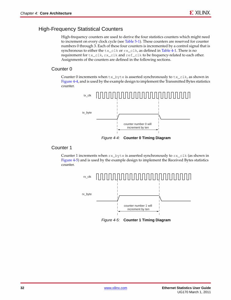
High-Frequency Statistical CountersHigh-frequency counters are used to derive the four statistics counters which might need to increment on every clock cycle (see Table 5-1). These counters are reserved for counter numbers 0 through 3. Each of these four counters is incremented by a control signal that is synchronous to either the tx_clk or rx_clk, as defined in Table 4-1. There is no requirement for tx_clk, rx_clk and ref_clk to be frequency-related to each other. Assignments of the counters are defined in the following sections.
Counter 0
Counter 0 increments when tx_byte is asserted synchronously to tx_clk, as shown in Figure 4-4, and is used by the example design to implement the Transmitted Bytes statistics counter.
Counter 1
Counter 1 increments when rx_byte is asserted synchronously to rx_clk (as shown in Figure 4-5) and is used by the example design to implement the Received Bytes statistics counter.
X-Ref Target - Figure 4-4
Figure 4-4: Counter 0 Timing Diagram
tx_clk
tx_byte
counter number 0 will increment by ten
X-Ref Target - Figure 4-5
Figure 4-5: Counter 1 Timing Diagram
rx_clk
rx_byte
counter number 1 will increment by ten

Ethernet Statistics User Guide www.xilinx.com 33UG170 March 1, 2011
Increment Interface
Counter 2
Counter 2 increments when rx_small is asserted synchronously to rx_clk (as shown in Figure 4-6) and is used by the example design to implement the Undersized Frames Received statistics counter.
Counter 3
Counter 3 increments when rx_frag is asserted synchronously to rx_clk (as shown in Figure 4-7) and is used by the example design to implement the Fragment Frames Received statistics counter.
X-Ref Target - Figure 4-6
Figure 4-6: Counter 2 Timing Diagram
rx_clk
rx_small
counter number 2 will increment by four
X-Ref Target - Figure 4-7
Figure 4-7: Counter 3 Timing Diagram
rx_clk
rx_frag
counter number 3 will increment by four

34 www.xilinx.com Ethernet Statistics User GuideUG170 March 1, 2011
Chapter 4: Core Architecture
Summary of the Increment InterfaceCompare this summary with the counters assigned by the example design. See Example Design Statistics, page 42.
High-Frequency Statistical Counters
Table 4-2 summarizes the high-frequency statistical counters, which are not flexible and might need to increment on every clock cycle.
Low-Frequency Statistical Counters
Table 4-3 summarizes the low-frequency statistical counters, which must only increment at (or less frequently than) the low-frequency increment period.
Table 4-2: Summary of High-Frequency Statistical Counters
Counter Number
Reserved For Derived from portsNumber of ref_clk Cycles Required
0 Transmitted bytes tx_clk
tx_byte
2
1 Received bytes rx_clk
rx_byte
2
2 Undersized Frames received
rx_clk
rx_small
2
3 Fragment Frames received rx_clk
rx_frag
2
Table 4-3: Summary of Low-Frequency Statistical Counters
Counter Numbers
Reserved For Derived From PortsNumber of
ref_clk Cycles Required
4-10 First group - only 1 counter within this group can increment at a time.
Used for the receiver frame size bins by the example design.
increment_vector[4:10] 2 per group
11-17 Second group - only 1 counter within this group can increment at a time.
Used for the transmitter frame size bins by the example design.
increment_vector[11:17] 2 per group
18 upwards Generic low frequency counters.
increment_vector[18+] 2 per counter

Ethernet Statistics User Guide www.xilinx.com 35UG170 March 1, 2011
Counter Reset Functionality
Counter Reset FunctionalityThe statistics counters are stored in Dual port RAM which can be implemented within either Block RAM or Distributed memory, depending upon the family. In both cases the values stored in these counters are not automatically cleared when there is a system reset. However, it is possible to configure the core to include counter reset logic which, effectively, clears all counters upon reset. See Statistics Clear on Reset in Chapter 2 for selecting this option.
Because there is no direct reset for the dual port RAM, this optional counter reset logic maintains a flag for each counter, indicating that it has been scheduled for reset. This flag is cleared after the counter has been written to zero by the read-modify-write process. If a CPU read is requested from a counter still scheduled for reset, the core logic ensures that the counter value returned is zero.
Core Reference Clock and ResetTable 4-4 describes the reference clock and reset for the core.
REF_CLK FrequencyThe Ethernet Statistics core is designed to enable a flexible clocking strategy around the entire core, including the frequency and derivation of ref_clk.
When using the core in conjunction with 1-Gigabit speed capable Ethernet MAC cores, it is expected that ref_clk will be shared with the 125 MHz system clock used by the MAC. This configuration was used as the basis of the study in Bandwidth Requirements, page 30.
However, the frequency of ref_clk can be unrelated to all other clocks. The frequency of ref_clk determines the number of statistical counters that can be used in a particular implementation. As previously described, there must be enough ref_clk cycles within the minimum legal Ethernet frame period to enable all statistics counters to be updated. Ethernet frame periods are defined for the Ethernet speeds as follows:
• 1 Gb/s: 584 ns
• 100 Mb/s: 5840 ns
• 10 Mb/s: 58400 ns
These frame periods are calculated by assuming the worst-case legal duration of 64 bytes of frame size, plus one byte of minimum received preamble, plus eight bytes of minimum received interframe gap at the respective bit rate for the relevant Ethernet speed.
The number of ref_clk cycles required for a selected number of statistics counters can be obtained by adding the values from Tables 4-2 and 4-3 in Summary of the Increment Interface, page 34.
Table 4-4: Reference Clock and Reset Signals
Signal DirectionClock
DomainDescription
ref_clk Input n/a Reference clock for the statistic core: this clocks all logic involved in the update of statistics counters.
ref_reset Input ref_clk Synchronous reset for the ref_clk logic domain.

36 www.xilinx.com Ethernet Statistics User GuideUG170 March 1, 2011
Chapter 4: Core Architecture
Example 1
This example illustrates the number of statistics counters that can be accommodated at 1- Gigabit Ethernet speeds with ref_clk set to 125 MHz.
• 73 ref_clk cycles are available (584 ns divided by 8 ns ref_clk period)
• Counters 0 to 3 require 2 ref_clk cycles each = 8 cycles
• Counters 4 to 10 require 2 ref_clk cycles
• Counters 11to 17 require 2 ref_clk cycles
• Counters 18 to 47 require 2 x 30 ref_clk cycles = 60
8+2+2+60 = 72 ref_clk cycles spent while implementing 48 counters.
Example 2
This example illustrates running the Tri-Mode Ethernet MAC core only at 10 Mb/s and 100 Mb/s speeds. We require 64 statistics counters. What is the minimum frequency of ref_clk?
• At 100Mb/s, the minimum legal Ethernet frame period is 5840 ns
• 64 statistics counters requires a total of 104 ref_clk cycles:
• 8 ref_clk cycles for counters 0 to 3
• 2 ref_clk cycles for counters 4 to 10
• 2 ref_clk cycles for counters 11to 17
• 2 x 46 = 92 ref_clk cycles for counters 18 to 63
• 5840 ns divided by 104 ref_clk cycles = 56 ns (ref_clk period).
For this reason, a minimum ref_clk frequency of 17.8 MHz is required.

Ethernet Statistics User Guide www.xilinx.com 37UG170 March 1, 2011
Management Interface
Management InterfaceTable 4-5 describes the Management Interface of the Ethernet Statistics core. The Management Interface can either be connected separately or can be shared with that of the chosen MAC. For sharing with a supported Ethernet MAC, see Chapter 8, Interfacing to Xilinx Ethernet MAC Cores.
Table 4-5: Management Interface Signals
Signal DirectionClock
DomainDescription
host_clk Input n/a Clock for the Management Interface.
host_reset Input host_clk Synchronous reset for the Management logic.
host_addr[9:0] Input host_clk Address of register to be accessed. Host_addr bit 9 must be set to 0 for all accesses. Bits 6-8 are not used.
host_req Input host_clk Used to initiate a Statistics Counter read transaction.
host_miim_sel Input host_clk When the Management Interface is shared with a supported Ethernet MAC and when set to logic ‘1,’ this causes the MAC to initiate an MDIO transaction.
For a statistical counter read, this must always be held at logic ‘0’ during a read transaction.
host_rd_data[31:0] Output host_clk The statistics counter value is presented on this port during a read transaction. This occurs over a two clock cycles: first the Least Significant Word (lower 32-bits) is presented on this port; on the subsequent clock cycle, the Most Significant Word (upper 32-bits) is then presented.
host_stats_lsw_rdy Output host_clk Asserted when the Least Significant Word (lower 32-bits) of the 64-bit statistical counter value is presented on host_rd_data[31:0].
host_stats_msw_rdy Output host_clk Asserted when the Most Significant Word (upper 32-bits) of the 64-bit statistical counter value is presented on host_rd_data[31:0].

38 www.xilinx.com Ethernet Statistics User GuideUG170 March 1, 2011
Chapter 4: Core Architecture
HOST_CLK FrequencyThe frequency of host_clk is very flexible. When the Management Interface is read by a microprocessor (for example, an embedded PowerPC® or MicroBlazeTM processor). It is expected that the Management Interface will be connected to and run at the same clock frequency as the embedded microprocessor bus.
The core itself places no limit on the lowest host_clk frequency. However, if the Management Interface is shared with a supported Xilinx Ethernet MAC, verify the host_clk frequency range that is supported by that MAC.
The maximum frequency of host_clk is limited by this Ethernet Statistics core. The frequency of host_clk must never exceed the frequency of ref_clk. However, host_clk and ref_clk can be connected and driven from the same clock source.
The Management Read TransactionFigure 4-8 illustrates reading from the Management Interface of the Ethernet Statistics core. Each specific counter can be individually addressed by placing the statistics counter number on the host_addr[9:0] port. Because the Management Interface is connected to port B of the Dual Port RAM (see Figure 4-1), any statistics counter can be read at any point.
X-Ref Target - Figure 4-8
Figure 4-8: Statistical Counter Read Transaction
host_clk
host_addr[8:0]
host_addr[9]
host_req
host_miim_sel
host_rd_data[31:0] LSW MSW
host_stats_lsw_rdy
host_stats_msw_rdy
6 Clocks

Ethernet Statistics User Guide www.xilinx.com 39UG170 March 1, 2011
Management Interface
Each statistics counter value is 64-bits wide and must be read in a two-cycle transfer; Figure 4-8 shows the timing. Six clock cycles after the read transaction is initiated, the Least Significant Word (LSW: lower 32-bits) of the counter value appears on the host_rd_data[31:0] port, and a clock cycle later the Most Significant Word (MSW: upper 32-bits) appears. This timing relationship is fixed for any host_clk frequency.
To aid in the sampling of the statistic values, host_stats_lsw_rdy is always asserted when the Least Significant Word is present on host_rd_data[31:0], and host_stats_msw_rdy is always asserted when the Most Significant Word is present (as illustrated). The use of these signals is optional.
Note: This description is applicable to both 64-bit and 32-bit statistics counter implementations (see Statistics Width, page 20). In the 32-bit implementation, the timing diagram is identical but the value placed on the Most Significant Word is always zero to ensure that two solutions are completely interchangeable within any application.

40 www.xilinx.com Ethernet Statistics User GuideUG170 March 1, 2011
Chapter 4: Core Architecture

Ethernet Statistics User Guide www.xilinx.com 41UG170 March 1, 2011
Chapter 5
Example Design Statistics Counters
This chapter defines the statistics counters implemented by the example design and introduces the concept of modifying the example design to implement alternate statistical counters.
Example Design Figure 5-1 illustrates the delivery of the Ethernet Statistics core through the CORE Generator™ software with an HDL example design built around the core. Xilinx recommends that you use the example design as the starting point for core integration. Example designs are provided for use with these Ethernet MACs:
• Embedded Tri-Mode Ethernet MAC
• Tri-Mode Ethernet MAC solutionX-Ref Target - Figure 5-1
Figure 5-1: Ethernet Statistics Example Design
Ethernet
Statistics
Core
Statistic Vector
Decoder
Increment
Vector
tx_statistics_vector
rx_statistics_vector
tx_statistics_valid
rx_statistics_valid
Ethernet Statistics Block Level (from example design)
Management Interface
(shared with the MAC)
Connect to
chosen
Ethernet
MAC

42 www.xilinx.com Ethernet Statistics User GuideUG170 March 1, 2011
Chapter 5: Example Design Statistics Counters
Figure 5-1 shows that the chosen MAC outputs its statistics in the form of statistic vectors, both for transmitter and receiver functions. A definition of these statistic vector outputs is outside the scope of this document; see the respective User Guide for the selected MAC.
The MAC statistic vectors are routed into the Statistic Vector Decoder module. As part of the example design, this is provided in HDL. This module decodes the vectors and implements the logic to derive each of the statistics counters. As such, this can be easily modified to create statistics counters for specific applications; see Modifying the Example Design, page 46 for details.
See Chapter 10, Detailed Example Design for a description of the directory and file structure, demonstration test bench, and scripts delivered by the CORE Generator system with the core netlist and example design.
Example Design StatisticsTables 5-1 through 5-4 define the 41 statistics provided by the example design. All 41 of these statistics are provided for the Embedded Ethernet MACs and the Tri-Mode Ethernet MAC. When using the Tri-Mode Ethernet MAC core in its Full-Duplex only configuration, only the first 34 of these counters (which are the non-half duplex counters) are required.
For all supported MACs, the example design only increments the received statistics counters for frames accepted by the MAC Address Filter. For this reason, if the Address Filter is disabled or not present (the MAC is performing promiscuous mode), all frames received by the MAC are counted. If the MAC Address Filter is enabled, only frames it accepts due to a destination address match are counted. See the appropriate MAC User Guide for Address Filter operation.
High-Frequency Statistical CountersTable 5-1 describes the High-Frequency Statistical Counters implemented by the example design. Cross reference with Table 4-2 from Chapter 4, Core Architecture.
Table 5-1: Example Design Statistics Counters 0 to 3
Address Name Description
0 Transmitted bytes A count of bytes of frames transmitted (destination address to frame check sequence inclusive).
1 Received bytes A count of bytes of frames received (destination address to frame check sequence inclusive).
2 Undersize frames received A count of the number of frames received (less than 64 bytes in length) but otherwise well formed.
3 Fragment frames received A count of the number of frames received (less than 64 bytes in length) with a bad frame check sequence field.

Ethernet Statistics User Guide www.xilinx.com 43UG170 March 1, 2011
Example Design Statistics
Low-Frequency Statistical CountersTable 5-2 describes the Low-Frequency Statistical Counters implemented by the example design. Counters 4 through to 10 comprise the first statistics counter group, used by the example design for the receiver statistics vector frame size bins. Cross reference this with Table 4-3 from Chapter 4, Core Architecture.
Table 5-3 defines counters 11 through 17, which comprise the second statistics counter group used by the example design for the transmitter statistics vector frame size bins. Cross reference this with Table 4-3 from Chapter 4, Core Architecture.
Table 5-2: Example Design Statistics Counters 4 to 10
Address Name Description
4 64 byte Frames Received OK
A count of error-free frames received that were 64 bytes in length.
5 65-127 byte Frames Received OK
A count of error-free frames received that were between 65 and 127 bytes in length.
6 128-255 byte Frames Received OK
A count of error-free frames received that were between 128 and 255 bytes in length.
7 256-511 byte Frames Received OK
A count of error-free frames received that were between 256 and 511 bytes in length.
8 512-1023 byte Frames Received OK
A count of error-free frames received that were between 512 and 1023 bytes in length.
9 1024-MaxFrameSize byte Frames Received OK
A count of error-free frames received that were between 1024 bytes and the specified IEEE 802.3-2008 maximum legal length.
10 Oversize Frames Received OK
A count of otherwise error-free frames received that exceeded the maximum legal frame length specified in IEEE 802.3-2008.
Table 5-3: Example Design Statistics Counters 11 to 17
Address Name Description
11 64 byte Frames Transmitted OK
A count of error-free frames transmitted that were 64 bytes in length.
12 65-127 byte Frames Transmitted OK
A count of error-free frames transmitted that were between 65 and 127 bytes in length.
13 128-255 byte Frames Transmitted OK
A count of error-free frames transmitted that were between 128 and 255 bytes in length.
14 256-511 byte Frames Transmitted OK
A count of error-free frames transmitted that were between 256 and 511 bytes in length.

44 www.xilinx.com Ethernet Statistics User GuideUG170 March 1, 2011
Chapter 5: Example Design Statistics Counters
Table 5-4 describes counters 18 through 40, which comprise the generic low frequency counters. Cross reference this with Table 4-3 from Chapter 4, Core Architecture.
15 512-1023 byte Frames Transmitted OK
A count of error-free frames transmitted that were between 512 and 1023 bytes in length.
16 1024-MaxFrameSize byte Frames Transmitted OK
A count of error-free frames transmitted that were between 1024 and the specified IEEE 802.3-2008 maximum legal length.
17 Oversize Frames Transmitted OK
A count of otherwise error-free frames transmitted that exceeded the maximum legal frame length specified in IEEE 802.3-2008.
Table 5-4: Example Design Statistics Counters 18 Upwards
Address Name Description
18 Frames Received OK A count of error-free frames received.
19 Frame Check Sequence Errors
A count of received frames that failed the CRC check and were at least 64 bytes in length.
20 Broadcast Frames Received OK
A count of frames that were successfully received and were directed to the broadcast group address.
21 Multicast Frames Received OK
A count of frames that were successfully received and were directed to a non broadcast group address.
22 Control Frames Received OK
A count of error-free frames received that contained the special Control Frame identifier in the length/type field.
23 Length/Type Out of Range A count of frames received that were at least 64 bytes in length where the length/type field contained a length value that did not match the number of MAC client data bytes received.
The counter also increments for frames in which the length/type field indicated that the frame contained padding, but where the number of MAC client data bytes received was greater than 64 bytes (minimum frame size).
The exception to the this is when the Length/Type Error Checks are disabled in the chosen MAC, in which case this counter does not increment.
24 VLAN Tagged Frames Received OK
A count of error-free VLAN frames received. This counter only increments when the receiver is configured for VLAN operation.
Table 5-3: Example Design Statistics Counters 11 to 17 (Continued)
Address Name Description

Ethernet Statistics User Guide www.xilinx.com 45UG170 March 1, 2011
Example Design Statistics
25 Pause Frames Received OK A count of error-free frames received that:
• Contained the MAC Control type identifier 88-08 in the length/type field
• Contained a destination address that matched either the MAC Control multicast address or the configured source address of the MAC
• Contained the PAUSE opcode• Were acted upon by the MAC
26 Control Frames Received with Unsupported Opcode
A count of error-free frames received that contained the MAC Control type identifier 88-08 in the length/type field but were received with an opcode other than the PAUSE opcode.
27 Frames Transmitted OK A count of error-free frames transmitted.
28 Broadcast Frames Transmitted OK
A count of error-free frames that were transmitted to the broadcast address.
29 Multicast Frames Transmitted OK
A count of error-free frames that were transmitted to a group destination address other than broadcast.
30 Underrun Errors A count of frames that would otherwise be transmitted by the core but could not be completed due to the assertion of TX_UNDERRUN during the frame transmission.
31 Control Frames Transmitted OK
A count of error-free frames transmitted that contained the MAC Control Frame type identifier 88-08 in the length/type field.
32 VLAN Tagged Frames Transmitted OK
A count of error-free VLAN frames transmitted. This counter only increments when the transmitter is configured for VLAN operation.
33 Pause Frames Transmitted OK
A count of error-free PAUSE frames generated and transmitted by the MAC in response to an assertion of pause_req.
34 Single Collision Frames A count of frames that are involved in a single collision but were subsequently transmitted successfully (half duplex mode only).
35 Multiple Collision Frames A count of frames that are involved in more than one collision but were subsequently transmitted successfully (half duplex mode only).
36 Frames with Deferred Transmissions
A count of frames in which transmission was delayed on its first attempt because the medium was busy (half duplex mode only).
Table 5-4: Example Design Statistics Counters 18 Upwards (Continued)
Address Name Description

46 www.xilinx.com Ethernet Statistics User GuideUG170 March 1, 2011
Chapter 5: Example Design Statistics Counters
Modifying the Example DesignSee Chapter 10, Detailed Example Design for a description of the directory and file structure, demonstration test bench, and scripts delivered by the CORE Generator software. Xilinx recommends that you become familiar with the example design HDL code before attempting any modifications.
The counters described in Example Design Statistics, page 42 are easily modifiable by editing the Vector Decoder modules HDL source code. An example of a single statistics counter modification is provided in the following section in both VHDL and Verilog.
Example Counter ModificationAs delivered by the example design, counter number 7 is defined in Table 5-2 as the 256-511 byte Frames Received OK statistic. This increments when an error-free frame, of a size within the range 256 bytes to 511 bytes, is received by the connected ethernet MAC. There are several statistic standards; see Appendix A, Relating the Statistics Counters to Statistical Specifications. Some of these standards, such as EtherStats, define counters within this range which increment regardless of whether the frame was error-free. For this reason, to make counter number 7 compatible with the equivalent EtherStats counter (by incrementing on both legal and errored frames), do the following:
37 Late Collisions A count of the times that a collision has been detected later than one slotTime from the start of the packet transmission. A late collision is counted twice: both as a collision and as a lateCollision (half duplex mode only).
38 Frames Aborted due to Excess collisions
A count of the frames that, due to excessive collisions, are not transmitted successfully (half duplex mode only).
39 Frames with Excess Deferral
A count of frames that deferred transmission for an excessive period of time (half duplex mode only).
40 Alignment Errors Asserted for received frames of size 64-bytes and greater which contained an odd number of received nibbles and which also contained an invalid FCS field.
Table 5-4: Example Design Statistics Counters 18 Upwards (Continued)
Address Name Description

Ethernet Statistics User Guide www.xilinx.com 47UG170 March 1, 2011
Modifying the Example Design
VHDL
Open the vector_decode.vhd file, which is part of the example design. Locate the following process:
-- Counter 7: "256-511 byte frames received OK" increment request -------------- counter7 : process(rx_clk) begin if (rx_clk'event and rx_clk = '1') then
if (rx_reset = '1') then inc_vector(7) <= '0';
elsif rx_stats_valid_reg = '1' then
-- toggle whenever an update is required if (rx_good_frame_reg and rx_256_511) = '1' then inc_vector(7) <= not inc_vector(7); end if;
end if; end if; end process counter7;
To make the modification, remove the good frame component from the highlighted line. The modified process becomes:
-- Counter 7: "256-511 byte frames received OK" increment request -------------- counter7 : process(rx_clk) begin if (rx_clk'event and rx_clk = '1') then
if (rx_reset = '1') then inc_vector(7) <= '0';
elsif rx_stats_valid_reg = '1' then
-- toggle whenever an update is required if (rx_256_511) = '1' then inc_vector(7) <= not inc_vector(7); end if;
end if; end if; end process counter7;
This modification can easily be repeated for other statistics counters.

48 www.xilinx.com Ethernet Statistics User GuideUG170 March 1, 2011
Chapter 5: Example Design Statistics Counters
Verilog
Open the vector_decode.v file, which is part of the example design. Locate the following always statement:
// Counter 7: "256-511 byte frames received OK" increment request //------------ always @(posedge rx_clk) begin if (rx_reset == 1'b1) inc_vector[7] <= 1'b0;
else if (rx_stats_valid_reg == 1'b1) begin // toggle whenever an update is required if (rx_good_frame_reg && rx_256_511 == 1'b1) inc_vector[7] <= !inc_vector[7];
end end
To make the modification, remove the good frame component from the highlighted line. The modified always statement becomes:
// Counter 7: "256-511 byte frames received OK" increment request //------------ always @(posedge rx_clk) begin if (rx_reset == 1'b1) inc_vector[7] <= 1'b0;
else if (rx_stats_valid_reg == 1'b1) begin // toggle whenever an update is required if (rx_256_511 == 1'b1) inc_vector[7] <= !inc_vector[7];
end end
This modification can easily be repeated for other statistics counters.
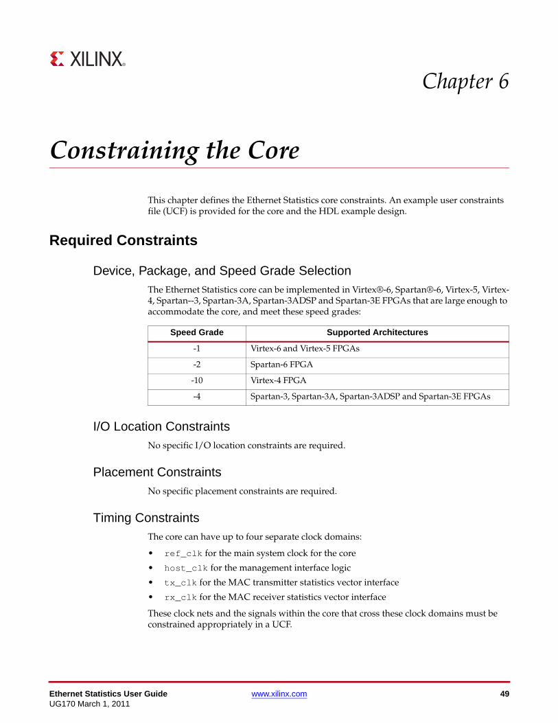
Ethernet Statistics User Guide www.xilinx.com 49UG170 March 1, 2011
Chapter 6
Constraining the Core
This chapter defines the Ethernet Statistics core constraints. An example user constraints file (UCF) is provided for the core and the HDL example design.
Required Constraints
Device, Package, and Speed Grade SelectionThe Ethernet Statistics core can be implemented in Virtex®-6, Spartan®-6, Virtex-5, Virtex-4, Spartan--3, Spartan-3A, Spartan-3ADSP and Spartan-3E FPGAs that are large enough to accommodate the core, and meet these speed grades:
I/O Location ConstraintsNo specific I/O location constraints are required.
Placement ConstraintsNo specific placement constraints are required.
Timing ConstraintsThe core can have up to four separate clock domains:
• ref_clk for the main system clock for the core
• host_clk for the management interface logic
• tx_clk for the MAC transmitter statistics vector interface
• rx_clk for the MAC receiver statistics vector interface
These clock nets and the signals within the core that cross these clock domains must be constrained appropriately in a UCF.
Speed Grade Supported Architectures
-1 Virtex-6 and Virtex-5 FPGAs
-2 Spartan-6 FPGA
-10 Virtex-4 FPGA
-4 Spartan-3, Spartan-3A, Spartan-3ADSP and Spartan-3E FPGAs

50 www.xilinx.com Ethernet Statistics User GuideUG170 March 1, 2011
Chapter 6: Constraining the Core
The constraints defined in this section are implemented in the example design UCF delivered with the core. Sections from this UCF are copied into the following descriptions to provide examples and should be studied in conjunction with the HDL source code for the example design.
PERIOD Constraints for Clock Nets
ref_clk
The clock provided to ref_clk must be constrained to the appropriate frequency. For most implementations, this is 125 MHz.
This UCF syntax shows the necessary constraints being applied to the ref_clk signal:
# Set the Reference clock period constraints:NET "ref_clk" TNM_NET = "ref_clk";TIMEGRP "ref_clock" = "ref_clk";TIMESPEC "TS_ref_clock" = PERIOD "ref_clock" 8000 ps HIGH 50 %;
host_clk
The clock provided to host_clk must be constrained to the desired Management Interface operating frequency. If host_clk is shared with ref_clk, this constraint is unnecessary and can be removed.
This UCF syntax shows a 100 MHz period constraint being applied to the host_clk:
# Set the Host clock period constraints:NET "host_clk" TNM_NET = "host_clk";TIMEGRP "host_clock" = "host_clk";TIMESPEC "TS_host_clock" = PERIOD "host_clock" 10000 ps HIGH 50 %;
tx_clk
The interface clock of the Ethernet MACs transmitter statistic vector must be constrained to the correct maximum frequency. This is 125 MHz for 1-Gigabit Ethernet rates.
The following UCF syntax shows the necessary constraints being applied to tx_clk, which is the relevant clock when interfacing to the TEMAC. This signal is exchanged with the txclientclkin clock signal when interfacing to an Embedded Tri-Mode Ethernet MAC (the correct signal name is automatically provided by the example design):
# Set the Tx clock period constraints:NET "tx_clk" TNM_NET = "tx_clk";TIMEGRP "tx_clock" = "tx_clk";TIMESPEC "TS_tx_clock" = PERIOD "tx_clock" 8000 ps HIGH 50 %;
rx_clk
The interface clock of the Ethernet MAC receiver statistic vector must be constrained to the correct maximum frequency. This is 125 MHz for 1-Gigabit Ethernet rates.
The following UCF syntax shows the necessary constraints being applied to rx_clk, which is the relevant clock when interfacing to the TEMAC. This signal is exchanged with the rxclientclkin clock signal when interfacing to an Embedded Tri-Mode Ethernet MAC (the correct signal name is automatically provided by the example design):
# Set the Rx clock period constraints:NET "rx_clk" TNM_NET = "rx_clk";TIMEGRP "rx_clock" = "rx_clk";TIMESPEC "TS_rx_clock" = PERIOD "rx_clock" 8000 ps HIGH 50 %;

Ethernet Statistics User Guide www.xilinx.com 51UG170 March 1, 2011
Required Constraints
Timespecs for Critical Logic within the Core
Signals must cross clock domains at certain points in the core, as follows.
host_clk to ref_clk
These constraints can be discarded when host_clk and ref_clk share the same source, otherwise they must be present.
When present, these must be constrained to a delay equal to the clock period of ref_clk. This is 8000 ps (125 MHz) in our example designs.
INST "core_wrapper/statistics_gathering/BU2/U0/statistics_width64?arch/request_toggle" TNM="stats_host_to_ref";INST "core_wrapper/statistics_gathering/BU2/U0/statistics_width64?arch/host_addr_sample*" TNM="stats_host_to_ref";TIMESPEC "TS_stats_host_to_ref" = FROM "stats_host_to_ref" TO "ref_clock" 8000 ps DATAPATHONLY;
ref_clk to host_clk
This constraint can be discarded when host_clk and ref_clk share the same source, otherwise it must be present.
When present, this must be constrained to a delay equal to the clock period of host_clk. This is currently constrained to 8000 ps (125 MHz) in our example designs.
INST "core_wrapper/statistics_gathering/BU2/U0/statistics_width64?arch/host_rd_clear" TNM="stats_ref_to_host";TIMESPEC "TS_stats_ref_to_host" = FROM "stats_ref_to_host" TO "host_clock" 8000 ps DATAPATHONLY;
TIMEGRP "all_rams" = RAMS("*");TIMESPEC "TS_stats_rams_to_host" = FROM "all_rams" TO "host_clock" 8000 ps DATAPATHONLY;
Cross Clock Domain Re-synchronizers
Where two flip-flop synchronizers are used to cross clock domains, it is necessary to apply a TIG on the first stage flip-flop. Where gray-code counters are passed across a clock domain boundary, a DATAPATHONLY constraint is applied to limit the skew across the bus.
INST "core_wrapper/statistics_gathering/BU2/U0/statistics_width64?arch/*sync_accum_gray_i/data_sync" TNM="sync_block_group";INST "core_wrapper/statistics_gathering/BU2/U0/statistics_width64?arch/sync_request/data_sync" TNM="sync_block_group";INST "core_wrapper/statistics_gathering/BU2/U0/statistics_width64?arch/*sync_inc_vector/data_sync" TNM="sync_block_group";
TIMESPEC "TS_stats_sync_block" = TO "sync_block_group" TIG;
INST "core_wrapper/statistics_gathering/BU2/U0/<=:blockstring:>?arch/*sync_accum_gray_i/data_sync" TNM="gray_code_group";
TIMESPEC "TS_stats_gray_code" = TO "gray_code_group" 8000 ps DATAPATHONLY;

52 www.xilinx.com Ethernet Statistics User GuideUG170 March 1, 2011
Chapter 6: Constraining the Core
IO Constraints
While the statistics core is not expected to have any external interfaces, the example design is coded to bring all the main interfaces off chip to interface to the demo test bench. To improve MAP and PAR results, offset constraints have been applied to these interfaces. These constraints can normally be removed.
For the Host interface the offset OUT constraints have been relaxed to enable timing to be achieved. As stated previously this interface would not normally be external and these constraints would be removed.
NET "host_addr<*>" OFFSET=IN 7900 ps BEFORE "host_clk";NET "host_req" OFFSET=IN 7900 ps BEFORE "host_clk";NET "host_miim_sel" OFFSET=IN 7900 ps BEFORE "host_clk";NET "host_rd_data<*>" OFFSET=OUT 9900 ps AFTER "host_clk";NET "host_stats_lsw_rdy" OFFSET=OUT 9900 ps AFTER "host_clk";NET "host_stats_msw_rdy" OFFSET=OUT 9900 ps AFTER "host_clk";
The following constraints are for the Tri-Mode Ethernet MAC, for the embedded MAC the relevant signal names are automatically substituted.
NET "tx_clk_en" OFFSET=IN 7 ns BEFORE "tx_clk";NET "tx_statistics_valid" OFFSET=IN 7 ns BEFORE "tx_clk";NET "tx_statistics_vector<*>" OFFSET=IN 7 ns BEFORE "tx_clk";
NET "rx_clk_en" OFFSET=IN 7 ns BEFORE "rx_clk";NET "rx_statistics_valid" OFFSET=IN 7 ns BEFORE "rx_clk";NET "rx_statistics_vector<*>" OFFSET=IN 7 ns BEFORE "rx_clk";

Ethernet Statistics User Guide www.xilinx.com 53UG170 March 1, 2011
Chapter 7
Implementing the Design
This chapter describes how to simulate and implement your design containing the Ethernet Statistics core.
Pre-implementation SimulationA functional model of the Ethernet Statistics core netlist is generated by the CORE Generator™ system to allow simulation during the design of the project.
Using the Simulation ModelFor information on setting up your simulator to use the pre-implemented model, see the Xilinx Synthesis and Verification Design Guide, included in your Xilinx® software installation.
The model is provided in the CORE Generator system project directory.
For VHDL Design Entry:
<component_name>.vhd
For Verilog Design Entry:
<component_name>.v
This model can be compiled along with the user code to simulate the overall system.

54 www.xilinx.com Ethernet Statistics User GuideUG170 March 1, 2011
Chapter 7: Implementing the Design
Synthesis
XST - VHDLIn the CORE Generator system project directory, there is a <component_name>.vho file that is a component and instantiation template for the core. Use this to help instance the Ethernet Statistics core into your VHDL source.
After your entire design is complete, create:
• An XST project file top_level_module_name.prj listing all the user source code files.
• An XST script file top_level_module_name.scr containing your required synthesis options.
To synthesize the design, run:
$ xst -ifn top_level_module_name.scr
See the XST User Guide for details about creating project and synthesis script files, and running the xst program.
XST - VerilogThere is a module declaration for the Ethernet Statistics core in the CORE Generator system project directory:
<component_name>/implement/<component_name>_mod.v
Use this module to help instance the Ethernet Statistics core into your Verilog source.
After your design is complete, do the following:
• Create an XST project file top_level_module_name.prj listing all the user source code files. Make sure you include
%XILINX%/verilog/src/iSE/unisim_comp.v
and
<component_name>/implement/<component_name>_mod.v
as the first two files in the project list.
• Create an XST script file top_level_module_name.scr containing your required synthesis options.
To synthesize the design, run:
$ xst -ifn top_level_module_name.scr
See the XST User Guide for details on creating project and synthesis script files, and running the xst program.

Ethernet Statistics User Guide www.xilinx.com 55UG170 March 1, 2011
Implementation
Implementation
Generating the Xilinx NetlistTo generate the Xilinx netlist, the ngdbuild tool is used to translate and merge the individual design netlists into a single design database—the NGD file. Also merged at this stage is the UCF for the design. An example of the ngdbuild command is:
$ ngdbuild -sd path_to_core_netlist -sd path_to_user_synth_results \
-uc top_level_module_name.ucf top_level_module_name
Mapping the DesignRun the map command to map the logic gates of the user design netlist into the CLBs and IOBs of the FPGA. The map command writes out a physical design to an NCD file. An example of the map command is:
$ map -timing -o top_level_module_name_map.ncd \
top_level_module_name.ngd top_level_module_name.pcf
Placing and Routing the DesignExecute the par command to place-and-route the user design logic components (mapped physical logic cells) contained within an NCD file in accordance with the layout and timing requirements specified within the PCF file. The par command outputs the placed and routed physical design to an NCD file. An example of the par command follows.
$ par top_level_module_name_map.ncd top_level_module_name.ncd \
top_level_module_name.pcf
Static Timing AnalysisExecute the trce command to evaluate timing closure on a design and create a timing report file (TWR) derived from static timing analysis of the physical design file (NCD). The analysis is typically based on constraints included in the optional PCF file. An example of the trce command follows.
$ trce -o top_level_module_name.twr top_level_module_name.ncd \
top_level_module_name.pcf
Generating a BitstreamExecute the bitgen command to create the configuration bitstream (BIT) file based on the contents of a physical implementation file (NCD). The BIT file defines the behavior of the programmed FPGA. An example of the bitgen command follows.
$ bitgen -w top_level_module_name.ncd
56 www.xilinx.com Ethernet Statistics User GuideUG170 March 1, 2011
Chapter 7: Implementing the Design
Post-Implementation SimulationThe purpose of post-implementation simulation is to verify that the design as implemented in the FPGA works as expected.
Generating a Simulation ModelRun the netgen command to generate a chip-level simulation netlist for your design.
VHDL
$ netgen -sim -ofmt vhdl -ngm top_level_module_name_map.ngm \
-tm netlist top_level_module_name.ncd \
top_level_module_name_postimp.vhd
Verilog
$ netgen -sim -ofmt verilog -ngm top_level_module_name_map.ngm \
-tm netlist top_level_module_name.ncd \
top_level_module_name_postimp.v
Using the ModelFor information on setting up your simulator to use the pre-implemented model, see the Xilinx Synthesis and Verification Design Guide included in your Xilinx software installation.
Other Implementation InformationFor details about using the Xilinx implementation tool flow, including command line switches and options, see the software manuals included with your Xilinx ISE® software.

Ethernet Statistics User Guide www.xilinx.com 57UG170 March 1, 2011
Chapter 8
Interfacing to Xilinx Ethernet MAC Cores
This chapter describes additional design considerations that are associated with implementing the Ethernet Statistics core with supported Xilinx® Ethernet MAC cores. These cores include the following:
• Embedded Tri-Mode Ethernet MAC
• LogiCORE™ IP Tri-Mode Ethernet MAC solution
Integrating with the Virtex-6 FPGA Embedded Tri-Mode Ethernet MAC
The Ethernet Statistics core can be integrated in a single device with the Virtex®-6 FPGA Embedded Tri-Mode Ethernet MAC core; however, a description of the Embedded Tri-Mode Ethernet MAC core is outside the scope of this document. For details, see the Virtex-6 FPGA product website:
www.xilinx.com/products/virtex6/index.htm
Figure 8-1 illustrates a single instance of a Virtex-6 FPGA Embedded Tri-Mode Ethernet MAC connected to the Ethernet Statistics solution. The block level from the example design can be directly connected. The Ethernet Statistics core and example design, as provided by CORE Generator™ system, are illustrated by the shaded component. In this example, the embedded MAC is shown when configured to use the Ethernet MAC Host Bus. See also Sharing the Management Interface, page 65. If the Embedded MAC is generated without clock enables, the clock enable inputs to the Ethernet Statistics core should be tied high.
For information on how to use the Ethernet Statistics core with the Virtex-6 FPGA Ethernet MAC, or alternatively to use the embedded MAC with the CoreConnect DCR bus as its Management Interface, see the Virtex-6 FPGA Tri-Mode Ethernet Media Access Controller User Guide.
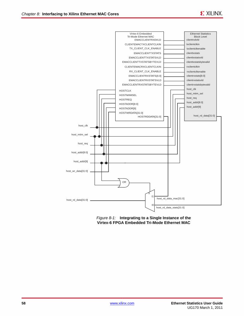
58 www.xilinx.com Ethernet Statistics User GuideUG170 March 1, 2011
Chapter 8: Interfacing to Xilinx Ethernet MAC Cores
X-Ref Target - Figure 8-1
Figure 8-1: Integrating to a Single Instance of the Virtex-6 FPGA Embedded Tri-Mode Ethernet MAC
Ethernet StatisticsBlock Level
Virtex-6 EmbeddedTri-Mode Ethernet MAC
host_clk
host_addr[8:0]
host_addr[9]
host_req
host_miim_sel
host_wr_data[31:0]
host_rd_data[31:0]
I0
I1
S
OR
HOSTCLK
HOSTADDR[8:0]
HOSTADDR[9]
HOSTREQ
HOSTMIIMSEL
HOSTWRDATA[31:0]
HOSTRDDATA[31:0]
host_clk
host_addr[8:0]
host_addr[9]
host_req
host_miim_sel
host_rd_data[31:0]
txclientclkin
clienttxstats
clienttxstatsvld
rxclientclkin
clientrxstats[6:0]
clientrxstatsvld
CLIENTEMACTXCLIENTCLKIN
EMACCLIENTTXSTATS
EMACCLIENTTXSTATSVLD
CLIENTEMACRXCLIENTCLKIN
EMACCLIENTRXSTATS(6:0]
EMAC#CLIENTRXSTATT TSVLDAA
clientrxdvldEMACCLIENTRXDVLD
host_rd_data_mac[31:0]
host_rd_data_stats[31:0]
EMACCLIENTRXSTATSBYTEVLD
clienttxstatsbytevalid
clientrxstatsbytevalid
EMACCLIENTTXSTATSBYTEVLD
txclientclkenableTX_CLIENT_CLK_ENABLE
EMACCLIENTRXSTATSVLD
rxclientclkenableRX_CLIENT_CLK_ENABLE

Ethernet Statistics User Guide www.xilinx.com 59UG170 March 1, 2011
Integrating with the Virtex-5 FPGA Embedded Tri-Mode Ethernet MAC
Integrating with the Virtex-5 FPGA Embedded Tri-Mode Ethernet MAC
The Ethernet Statistics core can be integrated in a single device with the Virtex-5 FPGA Embedded Tri-Mode Ethernet MAC core; however, a description of the Embedded Tri-Mode Ethernet MAC core is outside the scope of this document. For details, see the Virtex-5 FPGA Embedded Tri-Mode Ethernet MAC User Guide (UG194).
Figure 8-2 illustrates a single instance of a Virtex-5 FPGA Embedded Tri-Mode Ethernet MAC connected to the Ethernet Statistics solution. The block level from the example design can be directly connected. The Ethernet Statistics core and example design, as provided by CORE Generator system, are illustrated by the shaded component. In this example, the embedded MAC is shown when configured to use the Ethernet MAC Host Bus. See also Sharing the Management Interface, page 65. If the Embedded MAC is generated without clock enables, the clock enable inputs to the Ethernet Statistics core should be tied high.
For information on how to use the Ethernet Statistics core with the Virtex-5 FPGA Ethernet MAC pair, or alternatively to use the embedded MAC with the CoreConnect DCR bus as its Management Interface, see the Virtex-5 Tri-Mode Ethernet Media Access Controller User Guide.
Caution! Virtex-5 FPGA Embedded Tri-Mode Ethernet MAC components are provided in pairs. Figure 8-2 illustrates the use of only a single instance. When using both MACs from the pair, the Management Interface must be shared between both MACs.

60 www.xilinx.com Ethernet Statistics User GuideUG170 March 1, 2011
Chapter 8: Interfacing to Xilinx Ethernet MAC Cores
X-Ref Target - Figure 8-2
Figure 8-2: Integrating to a Single Instance of the Virtex-5 FPGA Embedded Tri-Mode Ethernet MAC
Ethernet StatisticsBlock Level
Virtex-5 EmbeddedTri-Mode Ethernet MAC
host_clk
host_addr[8:0]
host_addr[9]
host_req
host_miim_sel
host_wr_data[31:0]
host_rd_data[31:0]
I0
I1
S
OR
HOSTCLK
HOSTADDR[8:0]
HOSTADDR[9]
HOSTREQ
HOSTMIIMSEL
HOSTWRDATA[31:0]
HOSTRDDATA[31:0]
host_clk
host_addr[8:0]
host_addr[9]
host_req
host_miim_sel
host_rd_data[31:0]
txclientclkin
clienttxstats
clienttxstatsvld
rxclientclkin
clientrxstats[6:0]
clientrxstatsvld
CLIENTEMAC#TXCLIENTCLKIN
EMAC#CLIENTTXSTATS
EMAC#CLIENTTXSTATSVLD
CLIENTEMAC#RXCLIENTCLKIN
EMAC#CLIENTRXSTATS(6:0]
EMAC#CLIENTRXSTATT TSVLDAA
clientrxdvldEMAC#CLIENTRXDVLD
host_rd_data_mac[31:0]
host_rd_data_stats[31:0]
EMAC#CLIENTRXSTATSBYTEVLD
clienttxstatsbytevalid
clientrxstatsbytevalid
EMAC#CLIENTTXSTATSBYTEVLD
txclientclkenableTX_CLIENT_CLK_ENABLE_#
EMAC#CLIENTRXSTATSVLD
rxclientclkenableRX_CLIENT_CLK_ENABLE_#

Ethernet Statistics User Guide www.xilinx.com 61UG170 March 1, 2011
Integrating with Virtex-4 FPGA Embedded Tri-Mode Ethernet MAC
Integrating with Virtex-4 FPGA Embedded Tri-Mode Ethernet MACThe Ethernet Statistics core can be integrated in a single device with the Virtex-4 FPGA Embedded Tri-Mode Ethernet MAC core; however, a description of the Embedded Tri-Mode Ethernet MAC core is outside the scope of this document. For details, see the Virtex-4 FPGA Embedded Tri-Mode Ethernet MAC User Guide (UG074).
Figure 8-3 illustrates a single instance of a Virtex-4 FPGA Embedded Tri-Mode Ethernet MAC connected to the Ethernet Statistics solution. The block level from the example design can be directly connected. The Ethernet Statistics core and example design, as provided by the CORE Generator system, are illustrated by the shaded component. In this example, the embedded MAC is shown when configured to use the Ethernet MAC host bus. See also Sharing the Management Interface, page 65.
For information about using the Ethernet Statistics core with the Virtex-4 FPGA Ethernet MAC pair, or using the embedded MAC with the CoreConnect DCR bus as its Management Interface, see the Virtex-4 FPGA Tri-Mode Ethernet Media Access Controller User Guide.

62 www.xilinx.com Ethernet Statistics User GuideUG170 March 1, 2011
Chapter 8: Interfacing to Xilinx Ethernet MAC Cores
Caution! Virtex-4 FPGA embedded Tri-Mode Ethernet MAC components are provided in pairs. Figure 8-3 illustrates the use of only a single instance. When using both MACs from the pair, the Management Interface must be shared between both MACs.
X-Ref Target - Figure 8-3
Figure 8-3: Integrating to a Single Instance of the Virtex-4 FPGA Embedded Tri-Mode Ethernet MAC
Ethernet StatisticsBlock Level
Virtex-4 EmbeddedTri-Mode Ethernet MAC
host_clk
host_addr[8:0]
host_addr[9]
host_req
host_miim_sel
host_wr_data[31:0]
host_rd_data[31:0]
I0
I1
S
OR
HOSTCLK
HOSTADDR[8:0]
HOSTADDR[9]
HOSTREQ
HOSTMIIMSEL
HOSTWRDATA[31:0]
HOSTRDDATA[31:0]
host_clk
host_addr[8:0]
host_addr[9]
host_req
host_miim_sel
host_rd_data[31:0]
txclientclkin
clienttxstats
clienttxstatsvld
rxclientclkin
clientrxstats[6:0]
clientrxstatsvld
CLIENTEMAC#TXCLIENTCLKIN
EMAC#CLIENTTXSTATS
EMAC#CLIENTTXSTATSVLD
CLIENTEMAC#RXCLIENTCLKIN
EMAC#CLIENTRXSTATS(6:0]
EMAC#CLIENTRXSTATT TSVLDAA
clientrxdvldEMAC#CLIENTRXDVLD
host_rd_data_mac[31:0]
host_rd_data_stats[31:0]
EMAC#CLIENTRXSTATSBYTEVLD
clienttxstatsbytevalid
clientrxstatsbytevalid
EMAC#CLIENTTXSTATSBYTEVLD
txclientclkenable
EMAC#CLIENTRXSTATSVLD
rxclientclkenable
‘1’
‘1’

Ethernet Statistics User Guide www.xilinx.com 63UG170 March 1, 2011
Integrating with Tri-Mode Ethernet MAC Solution
Integrating with Tri-Mode Ethernet MAC SolutionThe Ethernet Statistics core can be integrated in a single device with the Tri-Mode Ethernet MAC solution IP cores. A description of the IP Update containing the Tri-Mode Ethernet MAC solution and instructions for obtaining the IP update are located on the Tri-Mode Ethernet MAC product page:
www.xilinx.com/products/ipcenter/TEMAC.htm
The Tri-Mode Ethernet MAC solution can be generated in a number of configurations. Most of these configurations have little effect on the statistics counters; however, it is possible to generate a Full-Duplex only version of the core. In this case the connectivity is as shown in Figure 8-4 but only the first 34 counters have any relevance.
Figure 8-4 illustrates a single instance of a Tri-Mode Ethernet MAC solution IP core connected to the Ethernet Statistics solution. The block level from the example design, as provided by CORE Generator system, can be connected directly as illustrated by the shaded component. In this example, the Tri-Mode Ethernet MAC solution is configured to use the optional clock enables. When the Tri-Mode Ethernet MAC solution is generated from CORE Generator system without the clock enables or in its 1 Gb/s only configuration, permanently tie the following Ethernet Statistic example design signals to logic 1:
• tx_clk_en
• rx_clk_en
All other connections remain unchanged.
See also Sharing the Management Interface, page 65.
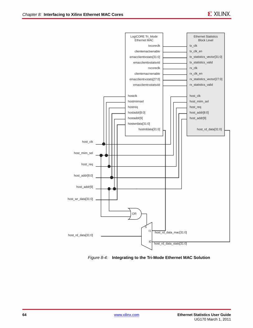
64 www.xilinx.com Ethernet Statistics User GuideUG170 March 1, 2011
Chapter 8: Interfacing to Xilinx Ethernet MAC Cores
X-Ref Target - Figure 8-4
Figure 8-4: Integrating to the Tri-Mode Ethernet MAC Solution
Ethernet StatisticsBlock Level
LogiCORE Tri_ModeEthernet MAC
host_clk
host_addr[8:0]
host_addr[9]
host_req
host_miim_sel
host_wr_data[31:0]
host_rd_data[31:0]
I0
I1S
hostclk
hostaddr[8:0]
hostaddr[9]
hostreq
hostmiimsel
hostwrdata[31:0]
hostrddata[31:0]
host_clk
host_addr[8:0]
host_addr[9]
host_req
host_miim_sel
host_rd_data[31:0]
tx_clk
tx_statistics_vector[31:0]
tx_statistics_valid
rx_clk_en
rx_statistics_vector[27:0]
rx_statistics_valid
clientemactxenable
emacclienttxstats[31:0]
emacclienttxstatsvld
clientemacrxenable
emacclientrxstats[27:0]
emacclientrxstatsvld
host_rd_data_mac[31:0]
host_rd_data_stats[31:0]
tx_clk_en
txcoreclk
rx_clkrxcoreclk
OR

Ethernet Statistics User Guide www.xilinx.com 65UG170 March 1, 2011
Sharing the Management Interface
Sharing the Management InterfaceIn the preceding examples for all MACs, common logic is used to share the management of the Ethernet Statistics core with the connected MAC. After implementing the logic shown, the Management Interface statistical counter read transaction is unchanged from that shown in Figure 4-8. In addition, all Management Interface transactions defined for the connected MAC remain unchanged.
This is achieved by avoiding data bus conflict in these ways:
• Selecting a different address range for the statistics to that of the MAC configuration registers.
Note: host_addr[9] must be logic 0 when reading from the statistics and is always logic 1 when writing and reading to the MAC configuration registers, thus avoiding an address range conflict.
• Using the host_miim_sel signal to differentiate between a statistical counter read and a MAC initiated MDIO transaction.
Note: host_miim_sel must be held at logic 0 for a statistical counter read; it must be held at logic 1 during a MAC initiated MDIO transaction.
Therefore, both host_addr[9] and host_miim_sel are used to select the correct MUXed host_data_rd[31:0] output between that provided from the MAC and that provided by the Ethernet Statistics core.
The code required to achieve this is provided in the following sections in both VHDL and Verilog. Signal names match those shown in Figures 8-3 through 8-4.
VHDL Example-- Multiplex the data read from either the MAC or the Statisticsmultiplex_read_data : process(host_miim_sel, host_addr, host_rd_data_mac, host_rd_data_stats) begin if host_miim_sel = '0' and host_addr(9) = '0' then host_rd_data <= host_rd_data_stats; else host_rd_data <= host_rd_data_mac; end if; end process;
Verilog Example // Multiplex the data read from either the MAC or the Statisticsalways @(host_miim_sel or host_addr or host_rd_data_mac or host_rd_data_stats)begin if (host_miim_sel == 1'b0 && host_addr[9] = 1'b0) host_rd_data <= host_rd_data_stats; else host_rd_data <= host_rd_data_mac;
end

66 www.xilinx.com Ethernet Statistics User GuideUG170 March 1, 2011
Chapter 8: Interfacing to Xilinx Ethernet MAC Cores

Ethernet Statistics User Guide www.xilinx.com 67UG170 March 1, 2011
Chapter 9
Quick Start Example Design
The instructions provided in this chapter help you to quickly generate an Ethernet Statistics core, run the core and example design provided through implementation with the Xilinx tools, and simulate the example design utilizing the provided demonstration test bench. For detailed information about the example design, see Chapter 10, Detailed Example Design.
OverviewThe Ethernet Statistics example design consists of the following:
• Ethernet Statistics core netlist
• HDL block wrapper and HDL vector decoder files, the part of the example design that should be instantiated in a customer design
• Example design HDL top-level for implementation in a device as a stand-alone design
• Demonstration test bench to exercise the example design
The Ethernet Statistics example design has been tested with Xilinx® ISE® v13.1 software, Cadence Incisive Enterprise Simulator (IES) v10.2, Mentor Graphics ModelSim v6.6d, and Synopsys VCS and VCS MX 2010.06.

68 www.xilinx.com Ethernet Statistics User GuideUG170 March 1, 2011
Chapter 9: Quick Start Example Design
X-Ref Target - Figure 9-1
Figure 9-1: Ethernet Statistics Example Design and Test Bench
Ethernet
Statistics
Core
Statistic Vector
Decoder
Increment
Vector
tx_statistics_vector
rx_statistics_vector
tx_statistics_valid
rx_statistics_valid
Ethernet Statistics Block Level
Management Interface
(shared with the MAC)
Demonstration Test Bench
Transmitter
Statistic
Vector
Stimulus
Receiver
Statistic
Vector
Stimulus
Management
Interface
Monitor
Ethernet Statistics Example Design

Ethernet Statistics User Guide www.xilinx.com 69UG170 March 1, 2011
Generating the Core
Generating the CoreUse these steps to generate the Ethernet Statistics example design.
1. Start the CORE Generator™ software.
For help starting and using the CORE Generator software, see the documentation supplied with ISE software at www.xilinx.com/support/software_manuals.htm.
2. Create a new project, either by choosing File > New Project or by clicking Create a New Project at the right side of the CORE Generator software window. After naming the project, the Project Options dialog box appears.
3. From the Family drop-down list, choose a Virtex®-5 FPGA part, which is used to generate an Ethernet Statistics core using the default parameters.
X-Ref Target - Figure 9-2
Figure 9-2: Project Options

70 www.xilinx.com Ethernet Statistics User GuideUG170 March 1, 2011
Chapter 9: Quick Start Example Design
4. Click the Generation tab; then select either VHDL or Verilog for Design Entry. For Vendor, select Other, and then click OK.
5. Locate the Ethernet Statistics core in the taxonomy tree, listed under one of the following:
• Communications & Networking/Ethernet
• Communications & Networking/Networking
• Communications & Networking/Telecommunications
6. Double-click the core name. A warning can appear related to the limitations of the Simulation Only Evaluation license.
X-Ref Target - Figure 9-3
Figure 9-3: Project Generation Options

Ethernet Statistics User Guide www.xilinx.com 71UG170 March 1, 2011
Implementing the Example Design
7. Click OK to display the Ethernet Statistics customization screen.
8. In the Component Name field, enter a name for the core instance; then click Finish to generate the core using the default parameters. The core and supporting files, including the example design, are generated in the project directory.
For a detailed description of the design example files and directories, see Chapter 10, Detailed Example Design.
Implementing the Example DesignAfter the core is generated, the netlists and example design can be processed by the Xilinx implementation tools. The generated output files include several scripts to assist you in running the Xilinx software.
From the CORE Generator software project directory window, type the following to implement the Ethernet Statistics example design:
For LINUX
linux-shell> cd <project_dir>/<component_name>/implement
linux-shell> ./implement.sh
For Windows
ms-dos> cd <project_dir>\<component_name>\implement
ms-dos> implement.bat
These commands execute a script that synthesizes, builds, maps, and place-and-routes the example design. The script then creates gate-level netlist HDL files in either VHDL or Verilog, along with associated timing information (SDF) files.
X-Ref Target - Figure 9-4
Figure 9-4: Customization Screen
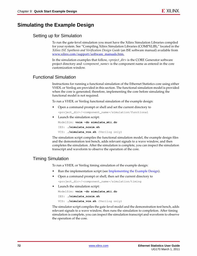
72 www.xilinx.com Ethernet Statistics User GuideUG170 March 1, 2011
Chapter 9: Quick Start Example Design
Simulating the Example Design
Setting up for SimulationTo run the gate-level simulation you must have the Xilinx Simulation Libraries compiled for your system. See “Compiling Xilinx Simulation Libraries (COMPXLIB),” located in the Xilinx ISE Synthesis and Verification Design Guide (an ISE software manual) available from www.xilinx.com/support/software_manuals.htm.
In the simulation examples that follow, <project_dir> is the CORE Generator software project directory and <component_name> is the component name as entered in the core customization window.
Functional SimulationInstructions for running a functional simulation of the Ethernet Statistics core using either VHDL or Verilog are provided in this section. The functional simulation model is provided when the core is generated; therefore, implementing the core before simulating the functional model is not required.
To run a VHDL or Verilog functional simulation of the example design:
• Open a command prompt or shell and set the current directory to
<project_dir>/<component_name>/simulation/functional
• Launch the simulation script:
ModelSim: vsim -do simulate_mti.do
IES: ./simulate_ncsim.sh
VCS: ./simulate_vcs.sh (Verilog only)
The simulation script compiles the functional simulation model, the example design files and the demonstration test bench, adds relevant signals to a wave window, and then completes the simulation. After the simulation is complete, you can inspect the simulation transcript and waveform to observe the operation of the core.
Timing SimulationTo run a VHDL or Verilog timing simulation of the example design:
• Run the implementation script (see Implementing the Example Design).
• Open a command prompt or shell, then set the current directory to
<project_dir>/<component_name>/simulation/timing
• Launch the simulation script:
ModelSim: vsim -do simulate_mti.do
IES: ./simulate_ncsim.sh
VCS: ./simulate_vcs.sh (Verilog only)
The simulator script compiles the gate-level model and the demonstration test bench, adds relevant signals to a wave window, then runs the simulation to completion. After timing simulation is complete, you can inspect the simulation transcript and waveform to observe the operation of the core.

Ethernet Statistics User Guide www.xilinx.com 73UG170 March 1, 2011
What’s Next?
What’s Next?For detailed information about the example design, including guidelines for modifying the design and extending the test bench, see Chapter 10, Detailed Example Design.

74 www.xilinx.com Ethernet Statistics User GuideUG170 March 1, 2011
Chapter 9: Quick Start Example Design

Ethernet Statistics User Guide www.xilinx.com 75UG170 March 1, 2011
Chapter 10
Detailed Example Design
This chapter provides detailed information about the Ethernet Statistics example design, including a description of files and the directory structure generated by the Xilinx® CORE Generator™ software, the purpose and contents of the provided scripts, the contents of the example HDL wrappers, and the operation of the demonstration test bench.
Directory Structure and File DescriptionsClick one of the following directory names to go to the desired directory and its associated files.
<project directory>Top-level project directory
<project directory>/<component name>Core release notes file
<component name>/docProduct documentation
<component name>/example_designVerilog and VHDL design files
<component name>/implementImplementation script files
implement/resultsCreated after implementation scripts are run and contain implement script results
<component name>/simulationSimulation scripts
simulation/functionalFunctional simulation files
simulation/timingTiming simulation files

76 www.xilinx.com Ethernet Statistics User GuideUG170 March 1, 2011
Chapter 10: Detailed Example Design
Directory and File ContentsThe Ethernet Statistics core directories and their associated files are defined in the following subsections.
<project directory>The project directory contains all the CORE Generator software project files.
<project directory>/<component name>The <component name> directory contains the release notes provided with the core, which contain last-minute changes and or updates.
Table 10-1: Project Directory
Name Description
<project_dir>
<component_name>.ngc The Xilinx netlist for the core, instantiated by the example design.
<component_name>.v[hd] The UniSim-based simulation model used to support the functional simulation of the core.
<component_name>.v{ho|eo} Instantiation template for the core.
<component_name>.xco A log file that records the settings used to generate a specific core. An XCO file is generated by the CORE Generator software for each core it creates in the current project directory. An XCO file can also be used as an input to the CORE Generator tool.
<component_name>_flist.txt A test file listing all the output files produced when a customized core is generated by the CORE Generator software.
Back to Top
Table 10-2: Component Name Directory
Name Description
<project_dir>/<component_name>
ethernet_statistics_readme.txt The core release notes text document.
Back to Top

Ethernet Statistics User Guide www.xilinx.com 77UG170 March 1, 2011
Directory and File Contents
<component name>/docThe doc directory contains the PDF documentation included with the core.
<component name>/example_designThe example design directory contains all the supporting Verilog or VHDL example design files included with the core.
Table 10-3: Doc Directory
Name Description
<project_dir>/<component_name>/doc
ethernet_statistics_ds323.pdf The Ethernet Statistics Data Sheet.
ethernet_statistics_ug170.pdf The Ethernet Statistics User Guide.
Back to Top
Table 10-4: Example Design Directory
Name Description
<project_dir>/<component_name>/example_design
<component_name>_example_design.v[hd] Top-level file for the example design, which allows the example design to be implemented in a device as a stand-alone design.
<component_name>_block.v[hd] The block-level file for the core. This is the useful part of the example design that should be instantiated in customer designs.
vector_decode.v[hd] The Ethernet MAC statistics vector decoder module instantiated from the block level. This entity defines the exact rules that increment each counter.
<component_name>_example_design.ucf An example UCF for the example design included with the core.
Back to Top

78 www.xilinx.com Ethernet Statistics User GuideUG170 March 1, 2011
Chapter 10: Detailed Example Design
<component name>/implementThe implement directory contains all the implementation script files.
implement/resultsThe results directory is created by the implement script; implement script results are placed in the results directory.
<component name>/simulationThe simulation directory and its subdirectories provide the files necessary to test a Verilog or VHDL implementation of the example design.
Table 10-5: Implement Directory
Name Description
<project_dir>/<component_name>/implement
implement.bat Windows batch file that process the example design through the Xilinx tool flow.
implement.sh LINUX shell script that processes the example design through the Xilinx tool flow.
xst.prj The XST project file for the example design, which enumerates all the VHDL files that need to be synthesized.
xst.scr XST example design script file.
Back to Top
Table 10-6: Results Directory
Name Description
<project_dir>/<component_name>/implement/results
These files are created by the implement scripts and contain the back-annotated Verilog or VHDL files.
Back to Top
Table 10-7: Simulation Directory
Name Description
<project_dir>/<component_name>/simulation
demo_tb.v[hd] The Verilog or VHDL demonstration test bench for the example design.
Back to Top

Ethernet Statistics User Guide www.xilinx.com 79UG170 March 1, 2011
Directory and File Contents
simulation/functionalThe functional directory contains lists of files for various types of simulation.
simulation/timingThe timing directory contains additional timing files.
Table 10-8: Functional Directory
Name Description
<project_dir>/<component_name>/simulation/functional
simulate_mti.do A ModelSim macro file that compiles the Verilog or VHDL sources and then runs the functional simulation to completion.
wave_mti.do A ModelSim macro (called by the simulate_mti.do macro) that opens a wave window and adds signals of interest.
simulate_ncsim.sh An IES script that compiles the Verilog or VHDL sources and then runs the functional simulation to completion.
wave_ncsim.sv An IES macro (called by the simulate_ncsim.sh script) that opens a wave window and adds signals of interest.
simulate_vcs.sh VCS script file that compiles the Verilog sources and runs the functional simulation to completion.
ucli_commands.key This file is sourced by VCS at the start of simulation: it configures the simulator.
vcs_session.tcl VCS macro file that opens a wave window and adds signals of interest to it. It is called by the simulate_vcs.sh script file
Back to Top
Table 10-9: Functional Directory
Name Description
<project_dir>/<component_name>/simulation/timing
simulate_mti.do A ModelSim macro that compiles the Verilog or VHDL sources, and then runs the timing simulation to completion.
wave_mti.do A ModelSim macro (called by the simulate_mti.do macro) that opens a wave window and adds signals of interest.
simulate_ncsim.sh An IES script that compiles the Verilog or VHDL sources and then runs the timing simulation to completion.

80 www.xilinx.com Ethernet Statistics User GuideUG170 March 1, 2011
Chapter 10: Detailed Example Design
Implementation ScriptsThe implementation script is either a shell script or batch file that processes the example design through the Xilinx tool flow. It is located at:
LINUX
<project_dir>/<component_name>/implement/implement.sh
Windows
<project_dir>/<component_name>/implement/implement.bat
The implement script performs these steps:
• Synthesizes the HDL example design files using XST
• Runs NGDbuild to consolidate the core netlist and the example design netlist into the NGD file containing the entire design
• Maps the design to the target technology
• Place-and-routes the design on the target device
• Performs static timing analysis on the routed design using Timing Analyzer (TRCE)
• Generates a bitstream
• Enables Netgen to run on the routed design to generate a VHDL or Verilog netlist (as appropriate for the Design Entry project setting) and timing information in the form of SDF files
The Xilinx tool flow generates several output and report files. These are saved in the following directory which is created by the implement script:
<project_dir>/<component_name>/implement/results
wave_ncsim.sv An IES macro (called by the simulate_ncsim.sh script) that opens a wave window and adds signals of interest.
simulate_vcs.sh VCS script file that compiles the Verilog sources and runs the timing simulation to completion.
ucli_commands.key This file is sourced by VCS at the start of simulation: it configures the simulator.
vcs_session.tcl VCS macro file that opens a wave window and adds signals of interest to it. It is called by the simulate_vcs.sh script file
Back to Top
Table 10-9: Functional Directory (Continued)
Name Description

Ethernet Statistics User Guide www.xilinx.com 81UG170 March 1, 2011
Simulation Scripts
Simulation Scripts
Functional SimulationThe test script, either a ModelSim, IES or VCS macro, automates the simulation of the test bench. The scripts are available from the following location:
<project_dir>/<component_name>/simulation/functional/
The test script performs these tasks:
• Compiles the structural UniSim simulation model
• Compiles HDL Example Design source code
• Compiles the demonstration test bench
• Starts a simulation of the test bench
• Opens a Wave window and adds signals of interest (wave_mti.do/wave_ncsim.sv)
• Runs the simulation to completion
Timing SimulationThe test script, either a ModelSim, IES or VCS macro, automates the simulation of the test bench. The scripts are available from the following location:
<project_dir>/<component_name>/simulation/timing/
The test script performs these tasks:
• Compiles the SimPrim based gate level netlist simulation model
• Compiles the demonstration test bench
• Starts a simulation of the test bench
• Opens a Wave window and adds signals of interest (wave_mti.do/wave_ncsim.sv)
• Runs the simulation to completion
Example Design
Top Level Example DesignThese files describe the top-level example design for the Ethernet Statistics core.
VHDL
<project_dir>/<component_name>/example_design/<component_name>_example_design.vhd
Verilog
<project_dir>/<component_name>/example_design/<component_name>_example_design.v
The top-level example design adds input and output flip-flops to the block level allowing the entire design to be synthesized and implemented in a target device to provide post place-and-route gate-level simulation.

82 www.xilinx.com Ethernet Statistics User GuideUG170 March 1, 2011
Chapter 10: Detailed Example Design
Block LevelThe following files describe the block-level design for the Ethernet Statistics core.
VHDL
<project_dir>/<component_name>/example_design/<component_name>_block.vhd
Verilog
<project_dir>/<component_name>/example_design/<component_name>_block.v
The HDL block-level design contains the following:
• An instance of the Ethernet Statistics core
• A Vector Decoder module which interprets the transmitter and receiver statistic vectors from the chosen Ethernet MAC
The block-level design should be instantiated in customer designs to connect to the chosen Ethernet MAC, as illustrated in Figure 10-1.X-Ref Target - Figure 10-1
Figure 10-1: Example Design Top-Level HDL for Ethernet Statistics Core
Ethernet
Statistics
Core
Statistic Vector
Decoder
Increment
Vector
tx_statistics_vector
rx_statistics_vector
tx_statistics_valid
rx_statistics_valid
Ethernet Statistics Block Level (from example design)
Management Interface
(shared with the MAC)
Connect to
chosen
Ethernet
MAC
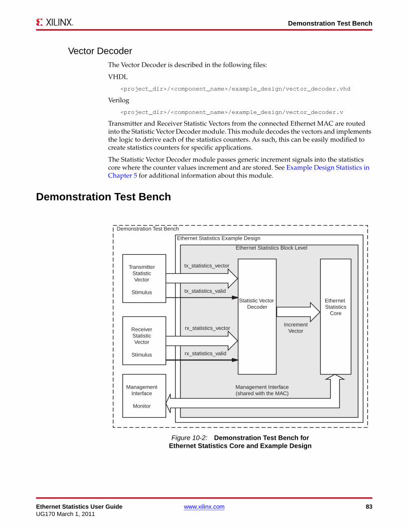
Ethernet Statistics User Guide www.xilinx.com 83UG170 March 1, 2011
Demonstration Test Bench
Vector DecoderThe Vector Decoder is described in the following files:
VHDL
<project_dir>/<component_name>/example_design/vector_decoder.vhd
Verilog
<project_dir>/<component_name>/example_design/vector_decoder.v
Transmitter and Receiver Statistic Vectors from the connected Ethernet MAC are routed into the Statistic Vector Decoder module. This module decodes the vectors and implements the logic to derive each of the statistics counters. As such, this can be easily modified to create statistics counters for specific applications.
The Statistic Vector Decoder module passes generic increment signals into the statistics core where the counter values increment and are stored. See Example Design Statistics in Chapter 5 for additional information about this module.
Demonstration Test Bench
X-Ref Target - Figure 10-2
Figure 10-2: Demonstration Test Bench for Ethernet Statistics Core and Example Design
Ethernet
Statistics
Core
Statistic Vector
Decoder
Increment
Vector
tx_statistics_vector
rx_statistics_vector
tx_statistics_valid
rx_statistics_valid
Ethernet Statistics Block Level
Management Interface
(shared with the MAC)
Demonstration Test Bench
Transmitter
Statistic
Vector
Stimulus
Receiver
Statistic
Vector
Stimulus
Management
Interface
Monitor
Ethernet Statistics Example Design

84 www.xilinx.com Ethernet Statistics User GuideUG170 March 1, 2011
Chapter 10: Detailed Example Design
The following files describe the demonstration test bench:
VHDL
<project_dir>/<component_name>/simulation/demo_tb.vhd
Verilog
<project_dir>/<component_name>/simulation/demo_tb.v
The demonstration test bench is a simple VHDL or Verilog program to exercise the example design and the core.
The demonstration test bench performs these tasks:
• Generates input clock signals
• Applies a reset to the example design
• Injects four Transmitter Statistic Vectors into the example design by the transmitter stimulus block. These simulate the following frames:
• The first frame is a minimum-length error free frame
• The second frame is a 65-byte frame, which is error free
• The third frame is a minimum-length frame, which has been errored by a TX_UNDERRUN assertion by the connected MAC
• The fourth frame is a minimum-length error free frame with a Broadcast Address
• Injects four Receiver Statistic Vectors are injected into the example design by the receiver stimulus block. These simulate the following frames:
• The first frame is a minimum-length error free frame
• The second frame is a minimum-length frame which is contains an Frame Check Sequence error
• The third frame is a 65-byte frame which is error free
• The fourth frame is a minimum-length error free frame with a Multicast Address
• After the Vectors are injected, the Management Interface performs a read from all statistic addresses. The following statistics are checked to ensure that the values read from the core are correct:
• Received bytes
• Frames Received OK
• Frame Check Sequence Errors
• Transmitted bytes
• Frames Transmitted OK
• Underrun Errors

Ethernet Statistics User Guide www.xilinx.com 85UG170 March 1, 2011
Demonstration Test Bench
Customizing the Test BenchThe core should be verified in a complete system when connected to the desired Ethernet MAC. However, when starting, follow these guidelines to modify the demonstration test bench provided with the core:
• It is possible to change the contents of the four transmitter and receiver statistic vectors which are injected into the core. The statistic checking performed during the Management read process should automatically update for the six statistics which are checked.
• New vectors can be added by defining new vectors of data. Make sure that the contents of these new vectors are passed into statistic_check function.
• Extra statistical checking can be added to the statistic_check function. Follow the six statistic examples already present.
• Clock frequencies applied to the core can be quickly modified for further testing.

86 www.xilinx.com Ethernet Statistics User GuideUG170 March 1, 2011
Chapter 10: Detailed Example Design

Ethernet Statistics User Guide www.xilinx.com 87UG170 March 1, 2011
Appendix A
Relating the Statistics Counters to Statistical Specifications
This appendix defines the relationship between the counters implemented in the example design and the counters defined in the following standards:
• IEEE 802.3-2008 Clause 30
• RFC1643
• RFC1757 (EtherStats)
Note: Counter naming conventions used in this document are identical to the naming conventions used in each of these specifications.
Xilinx does not claim that the statistics counters (as provided by the example design) conform to a specific specification. The information in this appendix is provided to be used as a guideline for performing statistical counter modifications. When modifying the counters for compliance with any specific specification, perform your own verification. Other counters can exist in these specifications that have no direct equivalent to those in the example design.

88 www.xilinx.com Ethernet Statistics User GuideUG170 March 1, 2011
Appendix A: Relating the Statistics Counters to Statistical Specifications
IEEE 802.3-2008 Clause 30Table A-1: Example Design Defined Statistics Counters Compared with IEEE 802.3 Clause 30
Address Name IEEE 802.3 Clause 30 Comparable Counter
0 Transmitted bytes Comparable with aOctetsTransmittedOK.
However, in our example design, all bytes from destination address to FCS field, inclusive, are counted (aOctetsTransmittedOK only counts the data and padding fields). Additionally, our example counter will increment for all transmitted frames (aOctetsTransmittedOK does not increment for frames counted as aFrameLostDueToIntMACsXmitError).
1 Received bytes Comparable with aOctetsReceivedOK.
However, in our example design, all bytes from the destination address to FCS field inclusive are counted (aOctetsReceivedOK only counts the data and padding fields). Additionally, our example counter will increment for all received frames (aOctetsReceivedOK does not increment for any frame which is counted as an error).
2 Undersize frames received
n/a
3 Fragment frames received
n/a
4 64 byte Frames Received OK
n/a
5 65-127 byte Frames Received OK
n/a
6 128-255 byte Frames Received OK
n/a
7 256-511 byte Frames Received OK
n/a
8 512-1023 byte Frames Received OK
n/a
9 1024-MaxFrameSize byte Frames Received OK
n/a
10 Oversize Frames Received OK
Similar to aFrameTooLongErrors but only otherwise error-free frames are counted.
11 64 byte Frames Transmitted OK
n/a
12 65-127 byte Frames Transmitted OK
n/a
13 128-255 byte Frames Transmitted OK
n/a
14 256-511 byte Frames Transmitted OK
n/a
15 512-1023 byte Frames Transmitted OK
n/a

Ethernet Statistics User Guide www.xilinx.com 89UG170 March 1, 2011
IEEE 802.3-2008 Clause 30
16 1024-MaxFrameSize byte Frames Transmitted OK
n/a
17 Oversize Frames Transmitted OK
n/a
18 Frames Received OK aFramesReceivedOK
19 Frame Check Sequence Errors
aFrameCheckSequenceErrors
20 Broadcast Frames Received OK
aBroadcastFramesReceivedOK
21 Multicast Frames Received OK
aMulticastFramesReceivedOK
22 Control Frames Received OK
aMACControlFramesReceived
23 Length/Type Out of Range
aInRangeLengthErrors
24 VLAN Tagged Frames Received OK
n/a
25 Pause Frames Received OK
apauseMACCtrlFramesReceived
26 Control Frames Received with Unsupported
Opcode
aUnsupportedOpcodesReceived
27 Frames Transmitted OK aFramesTransmittedOK
28 Broadcast Frames Transmitted OK
aBroadcastFramesXmittedOK
29 Multicast Frames Transmitted OK
aMulticastFramesXmittedOK
30 Underrun Errors aFrameLostDueToIntMACsXmitError
31 Control Frames Transmitted OK
aMACControlFramesTransmitted
32 VLAN Tagged Frames Transmitted OK
n/a
33 Pause Frames Transmitted OK
aPAUSEMACCtrlFramesTransmitted
34 Single Collision Frames aSingleCollisionFrames
35 Multiple Collision Frames
aMultipleCollisionFrames
36 Frames with Deferred Transmissions
aFramesWithDeferredXmissions
37 Late Collisions aLateCollisions
Table A-1: Example Design Defined Statistics Counters Compared with IEEE 802.3 Clause 30 (Continued)
Address Name IEEE 802.3 Clause 30 Comparable Counter

90 www.xilinx.com Ethernet Statistics User GuideUG170 March 1, 2011
Appendix A: Relating the Statistics Counters to Statistical Specifications
38 Frames Aborted due to Excess collisions
aFrameAbortedDueToXSCollisions
39 Frames with Excess Deferral
aFramesWithExcessiveDefferal
40 Alignment Errors aAlignmentErrors
Table A-1: Example Design Defined Statistics Counters Compared with IEEE 802.3 Clause 30 (Continued)
Address Name IEEE 802.3 Clause 30 Comparable Counter

Ethernet Statistics User Guide www.xilinx.com 91UG170 March 1, 2011
RFC1643
RFC1643Table A-2: Example Design Defined Statistics Counters Compared with RFC1643
Address Name RFC1643 Comparable Counter
0 Transmitted bytes n/a
1 Received bytes n/a
2 Undersize frames received
n/a
3 Fragment frames received
n/a
4 64 byte Frames Received OK
n/a
5 65-127 byte Frames Received OK
n/a
6 128-255 byte Frames Received OK
n/a
7 256-511 byte Frames Received OK
n/a
8 512-1023 byte Frames Received OK
n/a
9 1024-MaxFrameSize byte Frames Received OK
n/a
10 Oversize Frames Received OK
Similar to dot3StatsFrameTooLongs but only otherwise error-free frames are counted.
11 64 byte Frames Transmitted OK
n/a
12 65-127 byte Frames Transmitted OK
n/a
13 128-255 byte Frames Transmitted OK
n/a
14 256-511 byte Frames Transmitted OK
n/a
15 512-1023 byte Frames Transmitted OK
n/a
16 1024-MaxFrameSize byte Frames Transmitted OK
n/a
17 Oversize Frames Transmitted OK
n/a
18 Frames Received OK n/a
19 Frame Check Sequence Errors
dot3StatsFCSErrors
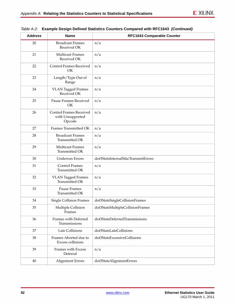
92 www.xilinx.com Ethernet Statistics User GuideUG170 March 1, 2011
Appendix A: Relating the Statistics Counters to Statistical Specifications
20 Broadcast Frames Received OK
n/a
21 Multicast Frames Received OK
n/a
22 Control Frames Received OK
n/a
23 Length/Type Out of Range
n/a
24 VLAN Tagged Frames Received OK
n/a
25 Pause Frames Received OK
n/a
26 Control Frames Received with Unsupported
Opcode
n/a
27 Frames Transmitted OK n/a
28 Broadcast Frames Transmitted OK
n/a
29 Multicast Frames Transmitted OK
n/a
30 Underrun Errors dot3StatsInternalMacTransmitErrors
31 Control Frames Transmitted OK
n/a
32 VLAN Tagged Frames Transmitted OK
n/a
33 Pause Frames Transmitted OK
n/a
34 Single Collision Frames dot3StatsSingleCollisionFrames
35 Multiple Collision Frames
dot3StatsMultipleCollisionFrames
36 Frames with Deferred Transmissions
dot3StatsDeferredTransmissions
37 Late Collisions dot3StatsLateCollisions
38 Frames Aborted due to Excess collisions
dot3StatsExcessiveCollisions
39 Frames with Excess Deferral
n/a
40 Alignment Errors dot3StatsAlignmentErrors
Table A-2: Example Design Defined Statistics Counters Compared with RFC1643 (Continued)
Address Name RFC1643 Comparable Counter

Ethernet Statistics User Guide www.xilinx.com 93UG170 March 1, 2011
RFC1757 (EtherStats)
RFC1757 (EtherStats)Table A-3: Example Design Defined Statistics Counters Compared with RFC1757 (EtherStats)
Address Name RFC1757 Comparable Counter
0 Transmitted bytes n/a
1 Received bytes etherStatsOctets
2 Undersize frames received
etherStatsUndersizePkts
3 Fragment frames received
etherStatsFragments
4 64 byte Frames Received OK
Similar to etherStatsPkts64Octets but only error free packets are counted.
5 65-127 byte Frames Received OK
Similar to etherStatsPkts65to127Octets but only error free packets are counted.
6 128-255 byte Frames Received OK
Similar to etherStatsPkts128to255Octets but only error free packets are counted.
7 256-511 byte Frames Received OK
Similar to etherStatsPkts256to511Octets but only error free packets are counted.
8 512-1023 byte Frames Received OK
Similar to etherStatsPkts512to1023Octets but only error free packets are counted.
9 1024-MaxFrameSize byte Frames Received OK
Similar to etherStatsPkts1024to1518Octets for none VLAN frames but only error-free packets are counted.
When receiving VLAN frames, the example design counter will increment for error-free frame sizes up to 1522 bytes. etherStatsPkts1024to1518Octets nevers increment for frames which exceed 1518 bytes.
10 Oversize Frames Received OK
Equivalent to etherStatsOversizePkts for none VLAN frames.
When receiving VLAN frames, the example design allows error-free frame sizes up to 1522 bytes without incrementing this counter. etherStatsOversizePkts will increment for otherwise error-free frames when they exceed 1518 bytes.
11 64 byte Frames Transmitted OK
n/a
12 65-127 byte Frames Transmitted OK
n/a
13 128-255 byte Frames Transmitted OK
n/a
14 256-511 byte Frames Transmitted OK
n/a
15 512-1023 byte Frames Transmitted OK
n/a
16 1024-MaxFrameSize byte Frames Transmitted OK
n/a

94 www.xilinx.com Ethernet Statistics User GuideUG170 March 1, 2011
Appendix A: Relating the Statistics Counters to Statistical Specifications
17 Oversize Frames Transmitted OK
n/a
18 Frames Received OK Similar to etherStatsPkts but only error-free packets are counted.
19 Frame Check Sequence Errors
Similar to etherStatsCRCAlignErrors, but the example design counts all packets which are greater than 64 bytes long (etherStatsCRCAlignErrors only counts the packets between 64 and 1518 bytes long inclusive).
20 Broadcast Frames Received OK
etherStatsBroadcastPkts
21 Multicast Frames Received OK
etherStatsMulticastPkts
22 Control Frames Received OK
n/a
23 Length/Type Out of Range
n/a
24 VLAN Tagged Frames Received OK
n/a
25 Pause Frames Received OK
n/a
26 Control Frames Received with Unsupported
Opcode
n/a
27 Frames Transmitted OK n/a
28 Broadcast Frames Transmitted OK
n/a
29 Multicast Frames Transmitted OK
n/a
30 Underrun Errors n/a
31 Control Frames Transmitted OK
n/a
32 VLAN Tagged Frames Transmitted OK
n/a
33 Pause Frames Transmitted OK
n/a
34 Single Collision Frames n/a
35 Multiple Collision Frames
n/a
36 Frames with Deferred Transmissions
n/a
37 Late Collisions n/a
Table A-3: Example Design Defined Statistics Counters Compared with RFC1757 (EtherStats) (Continued)
Address Name RFC1757 Comparable Counter

Ethernet Statistics User Guide www.xilinx.com 95UG170 March 1, 2011
RFC1757 (EtherStats)
38 Frames Aborted due to Excess collision
n/a
39 Frames with Excess Deferral
n/a
40 Alignment Errors n/a
Table A-3: Example Design Defined Statistics Counters Compared with RFC1757 (EtherStats) (Continued)
Address Name RFC1757 Comparable Counter

96 www.xilinx.com Ethernet Statistics User GuideUG170 March 1, 2011
Appendix A: Relating the Statistics Counters to Statistical Specifications