logical circuit design week 8: arithmetic circuits mentor hamiti, msc office 305.02,...
TRANSCRIPT

Logical Circuit Design
Week 8:
Arithmetic Circuits
Mentor Hamiti, MScOffice 305.02, [email protected] , (044)356-175

2
Last Time
Combinational Logic Circuits
• Decoders
• Encoders
• Multiplexers
• De-multiplexers
• Code converters
• Comparators

3
Contents
Combinational Arithmetic Circuits
• Adders
• Sub tractors
• Multipliers
• Dividers
• Other Circuits

4
Combinational Arithmetic Circuits
Arithmetic circuits are the ones which perform arithmetic operations like: addition, subtraction, multiplication, division, parity calculation, etc.
Most of the time, designing these circuits is the same or similar as designing:• Encoders,• Decoders,• Multiplexers,• De-multiplexers,• Code converters, etc.

5
Adders
Adders are the basic building blocks of all arithmetic circuits
Adders add two binary numbers and give out sum and carry as output• Example: X + Y = S + c
Basically we have two types of adders:
• Half Adder.
• Full Adder.
6
Half Adder
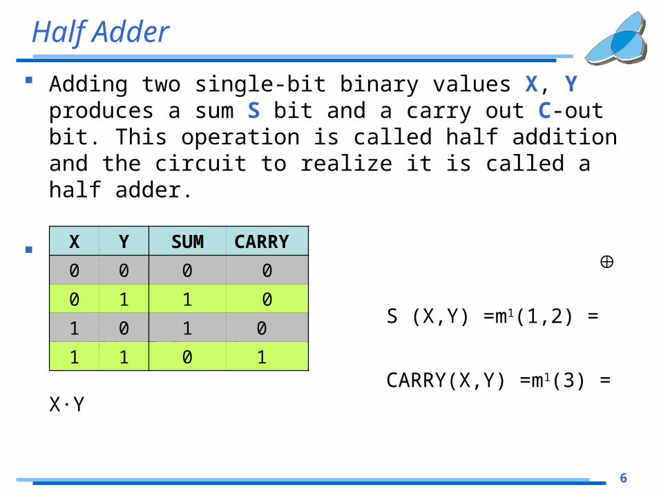
Adding two single-bit binary values X, Y produces a sum S bit and a carry out C-out bit. This operation is called half addition and the circuit to realize it is called a half adder.
Truth Table:
S (X,Y) =m1(1,2) = X'Y+XY‘ = X Y
CARRY(X,Y) =m1(3) = X·Y
X Y SUM CARRY
0 0 0 0
0 1 1 0
1 0 1 0
1 1 0 1

7
Half Adder
S(X,Y) =m1(1,2) = X'Y+XY‘ = X Y
CARRY(X,Y) =m1(3) = X·Y
Circuit:
Symbol:

8
Full Adder
Full adder takes a three-bits input. Adding two single-bit binary values X, Y with a carry input bit C-in produces a sum bit S and a carry out C-out bit.
Truth Table: K-Diagrams:
SUM=X Y Z
C=XY+YZ+XZ
X Y Z SUM
CARRY
0 0 0 0 0
0 0 1 1 0
0 1 0 1 0
0 1 1 0 1
1 0 0 1 0
1 0 1 0 1
1 1 0 0 1
1 1 1 1 1

9
Full Adder
SUM = X Y Z
Symbol:
CARRY = XY+YZ+XZ

10
n-bit (Carry Ripple) Adder An n-bit adder used to add two n-bit binary numbers can
be built by connecting n full adders in series.Each full adder represents a bit position j (from 0 to n-1).
Each carry out C-out from a full adder at position j is connected to the carry in C-in of the full adder at higher position j+1.The output of a full adder at position j is given by:
Sj = Xj Yj Cj
Cj+1 = Xj·Yj + Xj · Cj + Yj · Cj
In the expression of the sum Cj must be generated by the full adder at lower position j. The propagation delay in each full adder to produce the carry is equal to two gate delays = 2 D. Since the generation of the sum requires the propagation of the carry from the lowest position to the highest position, the total propagation delay of the adder is approximately:
• Total Propagation delay = 2 nD
11
4-bit Carry Ripple Adder
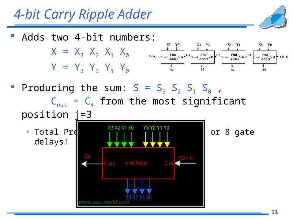
Adds two 4-bit numbers: X = X3 X2 X1 X0
Y = Y3 Y2 Y1 Y0
Producing the sum: S = S3 S2 S1 S0 ,Cout = C4 from the most significant position
j=3
• Total Propagation delay = 2 nD = 8D or 8 gate delays!

12
Larger Adder
Example: 16-bit adder using 4x4-bit adders.• Adds two 16-bit inputs X (bits X0 to X15), Y (bits Y0 to
Y15) producing a 16-bit Sum S (bits S0 to S15) and a carry out C16 from the most significant position
Propagation delay for 16-bit adder = 4 x propagation delay of 4-bit adder = 4 x 2 nD = 4 x 8D = 32 D or 32 gate delays
13
Carry Look-Ahead Adder
The delay generated by an N-bit adder is proportional to the length N of the two numbers X and Y that are added because the carry signals have to propagate from one full-adder to the next.
For large values of N, the delay becomes unacceptably large so that a special solution needs to be adopted to accelerate the calculation of the carry bits.
This solution involves a "look-ahead carry generator" which is a block that simultaneously calculates all the carry bits involved.
The design of the look-ahead carry generator involves two Boolean functions named Generate and Propagate. For each input bits pair these functions are defined as:
Gi = Xi · Yi
Pi = Xi + Yi

14
Carry Look-Ahead Adder
For a four-bit adder the carry-outs are calculated as follows:
carry_out0 = G0 + P0 . carry_in0
carry_out1 = G1 + P1 . carry_out0 = G1 + P1G0 + P1P0 . carry_in0
carry_out2 = G2 + P2G1 + P2P1G0 + P2P1P0 . carry_in0
carry_out3 = G3 + P3G2 + P3P2G1 + P3P2P1G0 + P3P2P1 . carry_in0

15
Subtractor
Subtractor circuits take two binary numbers as input and subtract one binary number input from the other binary number input.
Similar to adders, it gives out two outputs, difference and borrow.
There are two types of subtracters:
• Half Subtracter.
• Full Subtracter.

16
Half Subtracter
The half-subtracter is a combinational circuit which is used to perform subtraction of two bits.
It has two inputs, X (minuend) and Y (subtrahend) and two outputs D (difference) and B (borrow).
Truth Table: Boolean expressions:
Difference = XY’+X’Y Borrow = X’ Y
X Y D B
0 0 0 0
0 1 1 1
1 0 1 0
1 1 0 0

17
Half Subtracter
Difference = XY’+X’YBorrow = X’ Y
Circuit:
Symbol:
18
Full Subtracter
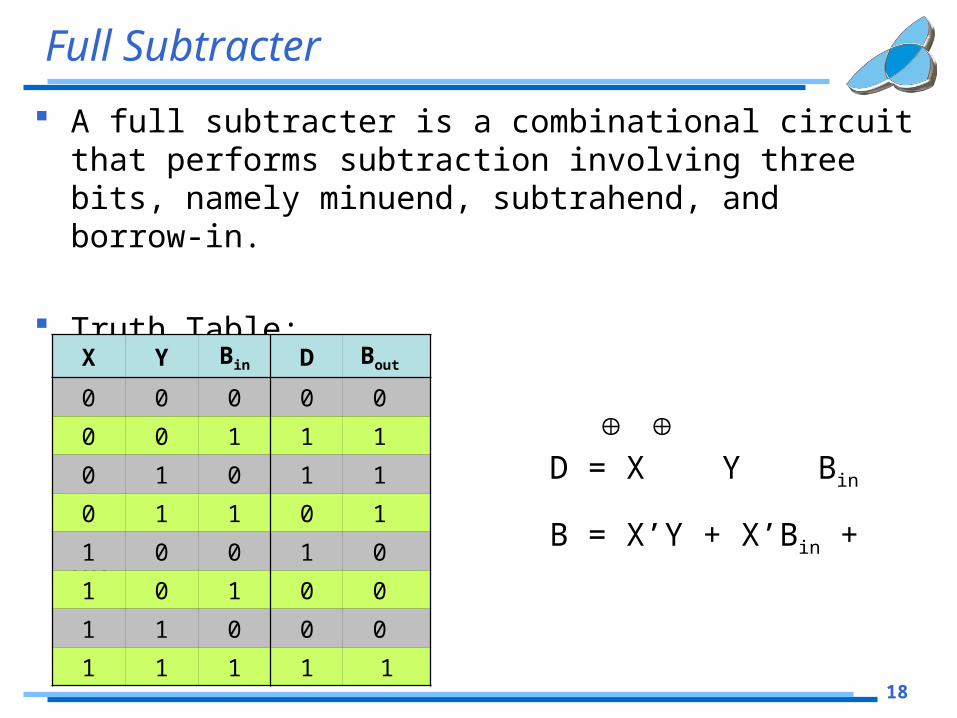
A full subtracter is a combinational circuit that performs subtraction involving three bits, namely minuend, subtrahend, and borrow-in.
Truth Table:
D = X Y Bin
B = X’Y + X’Bin + YBin
X Y Bin D Bout
0 0 0 0 0
0 0 1 1 1
0 1 0 1 1
0 1 1 0 1
1 0 0 1 0
1 0 1 0 0
1 1 0 0 0
1 1 1 1 1

19
Full Subtracter
D = X Y Bin
B = X’Y + X’Bin + YBin
Circuit:
Symbol:
20
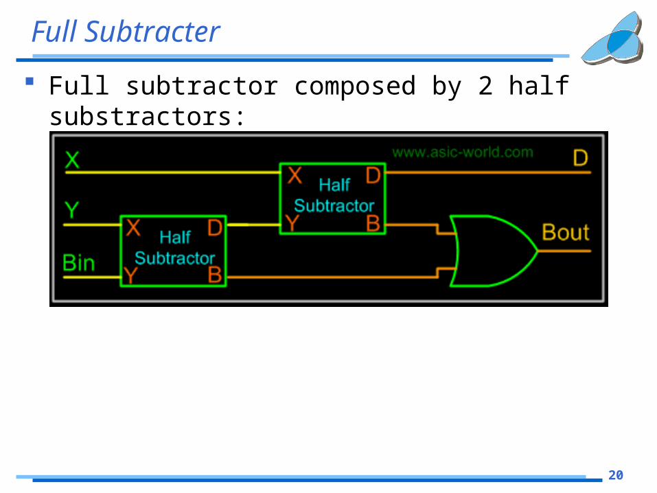
Full Subtracter
Full subtractor composed by 2 half substractors:
21
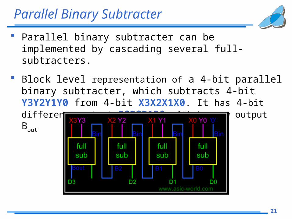
Parallel Binary Subtracter
Parallel binary subtracter can be implemented by cascading several full-subtracters.
Block level representation of a 4-bit parallel binary subtracter, which subtracts 4-bit Y3Y2Y1Y0 from 4-bit X3X2X1X0. It has 4-bit difference output D3D2D1D0 with borrow output Bout

22
Serial Binary Subtracter
A serial subtracter can be obtained by converting the serial adder using the 2's complement system.
The subtrahend is stored in the Y register and must be 2's complemented before it is added to the minuend stored in the X register.
The circuit for a 4-bit serial subtracter using full-adder:

23
Multipliers
Multiplication is achieved by adding a list of shifted multiplicands according to the digits of the multiplier.
An n-bit X n-bit multiplier can be realized in combinational circuitry by using an array of n-1 n-bit adders where each adder is shifted by one position.
For each adder one input is the shifted multiplicand multiplied by 0 or 1 (using AND gates) dependingon the multiplier bit, the other inputis n partial product bits.

24
Dividers
The binary divisions are performed in a very similar manner to the decimal divisions.
Thus, the second number is repeatedly subtracted from the figures of the first number after being multiplied either with '1' or with '0'.
The multiplication bit ('1' or '0') is selected for each subtraction step in such a manner that the subtraction result is not negative.
The division result is composed fromall the successive multiplication bitswhile the remainder is the result ofthe last subtraction step.

25
Other Circuits
Adder/Subtractor

26
Other Circuits
Arithmetic-Logic Unit (ALU)
Arithmetic Extender (AE)Logic Extender (LE)
