logic processing - leadercom.it · please note that for the first time, the directive covers...
TRANSCRIPT

Logic processing
Catalogue PDE2619TCUK October 2009

2
Parker Hannifin CorporationPneumatic Division - Europe
PDE2619TCUK
Logic Processing
Important !Before carrying out any service work, ensure that the valve and manifold have been vented. Remove the primary supply air hose to ensure total disconnection of the air supply before dismantling valves or blank connection blocks.
NB !All technical data in this catalogue is typical only.
The air quality is decisive for the valve life: see ISO 8573.
FAILURE OR IMPROPER SELECTION OR IMPROPER USE OF THE PRODUCTS AND/OR SYSTEMS DESCRIBED HEREIN OR RELATED ITEMS CAN CAUSE DEATH, PERSONAL INJURY ANDPROPERTY DAMAGE.This document and other information from Parker Hannifin Corporation, its subsidiaries and authorized distributors provide product and/or system options for further investigation by users having technical ex-pertise. It is important that you analyze all aspects of your application and review the information concerning the product or system in the current product catalog. Due to the variety of operating conditions and applications for these products or systems, the user, through its own analysis and testing, is solely responsible for making the final selection of the products and systems and assuring that all performance, safety and warning requirements of the application are met. The products described herein, including without limitation, product features, specifications, designs, availability and pricing, are subject to changeby Parker Hannifin Corporation and its subsidiaries at any time without notice.
WARNING
SALE CONDITIONSThe items described in this document are available for sale by Parker Hannifin Corporation, its subsidiaries or its authorized distributors. Any sale contract entered into by Parker will be governed bythe provisions stated in Parker’s standard terms and conditions of sale (copy available upon request).

3
Parker Hannifin CorporationPneumatic Division - Europe
PDE2619TCUK
Logic Processing
Summary...............................................................................................................................
Presentation...............................................................................................................
ATEX products..........................................................................................................................
Panorama - Operating informations..........................................................................................
Specific characteristics........................................................................................................
Modular sequencer....................................................................................................
Logic elements.....................................................................................................................
Sub-bases and timers..........................................................................................................
Amplifiers and sensor modules...............................................................................................
Electro-modules............................................................................................................
Impulse counters and timers............................................................................................................
Accessories....................................................................................................................
Spare parts...............................................................................................................................
Bases / Cells associations...........................................................................................
Dimensions..............................................................................................................
3
4 - 8
9 -11
12 - 13
14
11
17
18
19
20
21
22
23
24 - 25
26 - 29
Summary
Summary Page

4
Parker Hannifin CorporationPneumatic Division - Europe
PDE2619TCUK
Logic Processing
Line mounted logic elements
Presentation
Combinable logic elements
Sub-base mounting logic elements
These can either be mounted along the length of the
line or located in an enclosure.
Two logic functions are available with this model : AND
and OR.
These elements can be combined with each other
enabling the assembly of compact logic blocks. Three
logic functions are provided : AND - OR and inhibition
NOT.
In addition to the combination assembly by integral key,
each logic element includes a mode selector which
enables, simply by pivoting the selector, a choice
between cascade mode or common, input mode :
- cascade mode means that the element output
corresponds to the input of the following element ;
- common input mode sends one of the element's inputs
to an input of the following element.
The logic block obtained in this way for each
applications are mounted in an enclosure on standard
Omega rail, are connected by instant connections and
carry, on the front, their internal diagram to facilitate any
intervention.
As an alternative, it is possible to use logic element
suitable for mounting on 3-port sub-bases, the
interconnections being made by the sub-bases.
The following can be used :
- 3-port sub-bases with common pressure, with
common used as "input common" ;
- 3-port "cascade" sub-bases.
Selector incascade position
Selector incommon position

5
Parker Hannifin CorporationPneumatic Division - Europe
PDE2619TCUK
Logic Processing Presentation
The specialized relays mounted on stacking sub-bases
are complementary to the sequencers and logic
elements.
According to the relay, it can be used a 3-port or a
4-port sub-base.
3-port sub-bases
These are designed for the mounting of :
- timers,
- relays for bleed sensors,
- pressure operated electrical contacts.
4-ports sub-bases
These are designed for the mounting of :
- memory relays,
- amplifier relays for fluidic proxility sensors.
The standard configuration enables the use
of a single pressure supply to all the relays
by the centre ports ; this is why the stacking
"common pressure" sub-bases, with either
3 or 4 ports, are all designed to be used
singly or combined in a bank traversed by a
pressure common.
Air pressuresupply
Locking ofthe key by
thecomponent
Integralkey
Blankingplug

6
Parker Hannifin CorporationPneumatic Division - Europe
PDE2619TCUK
Logic Processing Presentation
The pneumatic sequencer facilitates the machine
adjustment dialogue and the optional dialogue.
At the step module level, dialogue items include :
- a step indicator which signals the step activated ;
- step reference marking ;
- manual overrides for resetting the module to 0 or to1;
- test point, enabling knowledge of the input and output
state of each module.
At the closure module level, the reference markings
enable :
- connection of loops A and B necessary for cycle
repetition ;
- switching on of the sequencer ;
-fitting of a reset (RESET) if the application requires
this.
Composition
Dialogue
The pneumatic sequencer comprises :
- the stage modules corresponding to the cycle to be
run : a module is used for each stage of the GRAFCET
function chart ;
- the two modules, head and tail, interlock the
association of the module onto Omega rail and enable
the connection of the pressure common, of the reset to
zero and the connection loops between the last and the
first module.
A deviation module is fitted between the step modules to
intercept the inter-module signals when the cycle includes
parallel elements, restarts or the skipping of a step.
Production machines fitted with pneumatic cylinders
generally repeat a defined sequencial cycle.
The pneumatic sequencer commands and controls the
correct operation of the required cycle.
Being modular, the sequencer can be easily configured
to each cycle encountered. It constitutes the backbone
of the pneumatic control.Logic elements and special relays are necessary to
ensure the additional functions : safety conditions,
operating modes, time delays, etc...
headmodule
stepmodule deviation
tailmodule
override movement test point
manual control for resetting the module to 0
step indicator
step referencemarking
feedback signal
manual control forresseting the module to 1
automaticconnectionsbetweenstep modules
Loop B
Loop A

7
Parker Hannifin CorporationPneumatic Division - Europe
PDE2619TCUK
Logic Processing Presentation
The sequencer reproduces the GRAFCET function
diagram configuration which defines the operating
cycle : a sequencer stage module corresponds to each
stage in the cycle.
The activated stage module sends the control signal to
the pressure valve controlling the action intended for
the stage, then waits for the feedback signal at the end
of this action before activating the next stage module in
the sequencer.
The all pneumatic loop shown in the diagram revolves
in this way around the stage module, the sequencer
activating stage by stage each of the actions to be
carried out in the cycle order.
Setting up
Example
This very simple example shows a pneumatic press
fitted with a part supply cylinder.
A bistable power valve and end of travel sensors are
associated with each cylinder.
The GRAFCET diagram defines the required cycle. The
initial stage is placed at the end to facilitate obtaining
the cycle via the sequencer.
In the diagram, the sequencer reproduces the GRAFCET
diagram, sending step by step control signals (a+, a-,
b+, b-) according to the feedback signals (a1, a0, b1,
b0).
Startingcycle

8
Parker Hannifin CorporationPneumatic Division - Europe
PDE2619TCUK
Logic Processing Presentation
Basic features
Output S is ON only
if inputs "a" AND "b"
are ON.
Output S is ON if
at least one of the
inputs "a" OR "b"
is ON.
Output S is ON and
regenerated if input
"a" is ON.
"b" is an intermittent
signal. "a" inhibits
"b". Output S is ON
if "b" is ON and "a"
is OFF.
Output S is ON if
input "a" is OFF
(and if supply P is
present).
Input "a" generates
output S (SET).
Output S remains
ON until removed
by input "b"
(RESET).
OR
AND
YES(Regenerate)
MEMORY
NOT(Inhibit)
Logic Function
Logic Symbol
Pneumatic Component
FunctionSymbol
Electrical Equivalent
PASSIVE
FUNCTIONS
ACTIVE
FUNCTIONS
S = a OR b (or both)S = a + b
S = a and bS = ab
S = a (Regenerated)
S = NOT aS = a
S = ab

9
Parker Hannifin CorporationPneumatic Division - Europe
PDE2619TCUK
Logic Processing ATEX products
ATEX - Ex products compliance
Some products (PLL-, PLK-, PLN-, PLJ-, PLM-, PRD-, PRF-, PRT-, PSM-, PSV-A1) are available certified ATEX Labels II 2 GD c 85 °C zones 1, 2, 21, 22 certification n° LCIE 04 ATEX 6164X. All these products are marked with * in this technical leaflet.To obtain the ATEX version of the product, add -EX at the end of the order code Eg : PSM-A12-EX For more information please refer to ATEX Components technical leaflet : PDE2584TCUK-ev

10
Parker Hannifin CorporationPneumatic Division - Europe
PDE2619TCUK
Logic Processing
Introduction to the European ATEX directiveExplosive atmospheresDirective 94/9/EC defines an explosive atmosphere as a mixture of :
a) flammable substances – gases, vapours, mists or dusts
b) with airc) under specific atmospheric conditionsd) in which, after ignition has occurred, combustion spreads to the
entire flammable mixture
(NB: with regard to dust, it may be that not all dust is combusted after ignition has occurred)
An atmosphere with the potential to become an explosive atmosphere during operating conditions and/or under the influence of the surroundings is defined as a potentially explosive atmosphere. Products covered by directive 94/9/EC are defined as intended for use in potentially explosive atmospheres.
Harmonised European ATEX standardThe European Union has adopted two harmonised directives in the field of health and safety. The directives are known as ATEX 100a and ATEX 137.
Directive ATEX 100a (94/9/EC) lays down minimum safety requirements for products intended for use in potentially explosive atmospheres in European Union member states. Directive ATEX 137 (99/92/EC) defines minimum requirements for health and safety at the workplace, for working conditions and for the handling of products and materials in potentially explosive atmospheres. This directive also divides the workplace into zones and defines criteria by which products are categorised within these zones. The table below describes the zones in an installation where there is a potential for explosive atmospheres. The owner of the installation must analyse and assess the area in which the explosive gas/dust mixture may occur, and if necessary must divide it into zones. This process of zoning then allows the correct plant and equipment to be selected for use in the area.
The ATEX directive has been in force throughout the European Union since 1 July 2003, replacing the existing divergent national and European legislation relating to explosive atmospheres.Please note that for the first time, the directive covers mechanical, hydraulic and pneumatic equipment and not just electrical equipment as before.
With regard to the Machinery directive 98/37/EC, note that a number of external requirements in 94/9/EC refer to hazards arising from potentially explosive atmospheres, where the Machinery directive only contains general requirements relating to explosion safety (Annex I 1.5.7).
As a result, directive 94/9/EC (ATEX 100a) takes precedence over the Machinery directive with regard to explosion protection in potentially explosive atmospheres. The requirements in the Machinery directive are applicable to all other risks relating to machinery.
Zones Presence of potentially explosive atmosphere Type of risk Gas Dust G D 0 20 Present continuously or for long periods. Permanent.
1 21 Likely to occur in normal operation occasionally. Potential.
2 22 Not likely to occur in normal operation but, if it does occur, Minimal. will persist for a short period only.
Zone 1Category 2
Zone 2Category 3
Zone 0Category 1
In most cases full certification is not required, a much more simple ”Risk Assessment” as detailed in the Directive,for the products to be supplied will suffice. At the moment we are conducting ”Risk Assessments” in ac-cordance with the Directive, on a broad range of core products which will be published on the web site. A more limited range of products will have the full ATEX certification where this is deemed necessary.
ATEX = “ATmosphère EXplosible”
11
Parker Hannifin CorporationPneumatic Division - Europe
PDE2619TCUK
Logic Processing
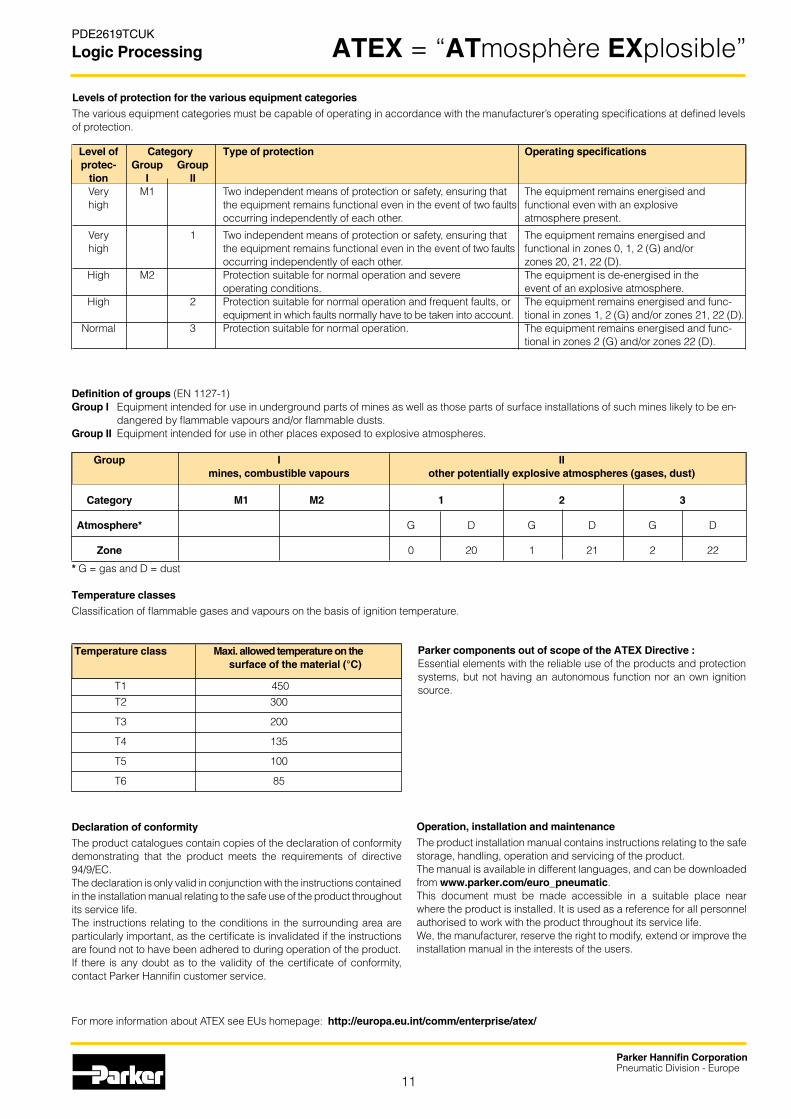
Parker components out of scope of the ATEX Directive :Essential elements with the reliable use of the products and protection systems, but not having an autonomous function nor an own ignition source.
Levels of protection for the various equipment categoriesThe various equipment categories must be capable of operating in accordance with the manufacturer’s operating specifications at defined levels of protection.
Level of Category Type of protection Operating specifications protec- Group Group tion I II Very M1 Two independent means of protection or safety, ensuring that The equipment remains energised and high the equipment remains functional even in the event of two faults functional even with an explosive occurring independently of each other. atmosphere present.
Very 1 Two independent means of protection or safety, ensuring that The equipment remains energised and high the equipment remains functional even in the event of two faults functional in zones 0, 1, 2 (G) and/or occurring independently of each other. zones 20, 21, 22 (D). High M2 Protection suitable for normal operation and severe The equipment is de-energised in the operating conditions. event of an explosive atmosphere. High 2 Protection suitable for normal operation and frequent faults, or The equipment remains energised and func- equipment in which faults normally have to be taken into account. tional in zones 1, 2 (G) and/or zones 21, 22 (D). Normal 3 Protection suitable for normal operation. The equipment remains energised and func- tional in zones 2 (G) and/or zones 22 (D).
* G = gas and D = dust
Temperature classesClassification of flammable gases and vapours on the basis of ignition temperature.
Group I II mines, combustible vapours other potentially explosive atmospheres (gases, dust)
Category M1 M2 1 2 3
Atmosphere* G D G D G D
Zone 0 20 1 21 2 22
Declaration of conformityThe product catalogues contain copies of the declaration of conformity demonstrating that the product meets the requirements of directive 94/9/EC.The declaration is only valid in conjunction with the instructions contained in the installation manual relating to the safe use of the product throughout its service life. The instructions relating to the conditions in the surrounding area are particularly important, as the certificate is invalidated if the instructions are found not to have been adhered to during operation of the product.If there is any doubt as to the validity of the certificate of conformity, contact Parker Hannifin customer service.
Temperature class Maxi. allowed temperature on the surface of the material (°C)
T1 450 T2 300
T3 200
T4 135
T5 100
T6 85
Operation, installation and maintenanceThe product installation manual contains instructions relating to the safe storage, handling, operation and servicing of the product.The manual is available in different languages, and can be downloaded from www.parker.com/euro_pneumatic.This document must be made accessible in a suitable place near where the product is installed. It is used as a reference for all personnel authorised to work with the product throughout its service life. We, the manufacturer, reserve the right to modify, extend or improve the installation manual in the interests of the users.
For more information about ATEX see EUs homepage: http://europa.eu.int/comm/enterprise/atex/
Definition of groups (EN 1127-1)Group I Equipment intended for use in underground parts of mines as well as those parts of surface installations of such mines likely to be en-
dangered by flammable vapours and/or flammable dusts.Group II Equipment intended for use in other places exposed to explosive atmospheres.
ATEX = “ATmosphère EXplosible”

12
Parker Hannifin CorporationPneumatic Division - Europe
PDE2619TCUK
Logic Processing
Pneumatic automation; Control module Time delay Relay
Relay function
Series PSM, PLM PLL, PLK PLL, PLK PLN- , PLJ PRT PLMFunction Modular Stand alone Stackable Subbase mtd Time relay Memory sequencer logic cell logic cell logic cell Pneum. Relay Relay
Operating Pressure 3 to 8 bar 3 to 8 bar 3 to 8 bar 3 to 8 bar 3 to 8 bar 3 to 8 bar
Storage temperature -40 °C to +70 °C -40 °C to +70 °C -40 °C to +70 °C -40 °C to +70 °C -40 °C to +70 °C -40 °C to +70 °C
Working temperature -15 °C to +60 °C -15 °C to +60 °C -15 °C to +60 °C -15°C to +60 °C -15 °C to +60 °C -15 °C to +60 °C
Flow, Nl/min at 6 bar 180 180 180 90/180 180 180
Flow, Kv 1,8 1,8 1,8 1/1,8 1,8 1,8
Response time Commuting time of the primary acting cell: 2 to 3 ms
Mechanical life at 6 bar, 10 million 100 million 100 million 10 million 10 million 10 million 20 °C 1 Hz cycles cycles cycles cycles cycles cycles
Shocks and Vibrations According to IEC 68-2-6 and IEC 68-2-27
Connection Push-in connection Ø4 mm
Mounting All positions All positions All positions All positions All positions All positions
Refer to page 15 16 17 17 18 19
DC
Material General Characteristics
Valve member - seat : Self lubricating acetal - ceramicBody : Polyamide reinforced fibreglassCasing - End plates : Anodised aluminium Valve plate : ZamakSeals : NitrileSprings : Stainless steelScrews : Stainless steelPoppets : Polyuréthane
Fluid : Air or inert gas filtered 40 µ class 5 according to ISO 8573-1 dry class according to service temperature non-lubricated, or lubricatedStorage temperature : -40 °C to + 70 °CLow temperature climatic : According to EN 60068-2-1, test Ad High temperature climatic : According to EN 60068-2-2, test BdShock and Vibrations : According to IEC 68-2-6 and IEC 68-2-27Salt spray test : According to ISO 9227, 168 hSolenoid orifice : 1.2/1.3mm Power (DC) : 6 to 6.8WVoltage tolerance : +/- 30%Duty cycle : 100%Electrical connection : Din A

13
Parker Hannifin CorporationPneumatic Division - Europe
PDE2619TCUK
Logic Processing
Relay functions
PRD PRF PRE, PS1 PRS PCT, PCP 2147 PCM Amplifier Sensor Pressure Solenoid Counter Binary Timers relay relay switch actuator Counter
3 to 8 bar 3 to 8 bar 3 to 8 bar 3 to 8 bar 2 to 8 bar 0 to 10 bar 2 to 6 bar
-40 °C to +70 °C -40 °C to +70 °C -40 °C to +70 °C -40 °C to +70 °C 0 °C to +60 °C 0 °C to +70 °C -40 °C to +70 °C
-15 °C to +60 °C -15 °C to +60 °C -15 °C to +60 °C -15 °C to +40 °C 0 °C to +60 °C 0 °C to +60 °C
90 180 - 60 - 460 100
1 1,8 - 0,65 - - -
Commuting time of the primary 2 to 3 ms 8 to 12 ms Reset time Reset time acting cell: 2 to 3 ms 150 ms 200 ms
10 million 10 million 10 million 10 million 10 million 50 million 5 million cycles cycles cycles cycles cycles cycles cycles
According to IEC 68-2-6 and IEC 68-2-27
Push-in connection Ø4 mm
All positions All positions All positions All positions All positions All positions All positions
19 19 20 20 21 21 21
Pressure Switch
Solenoid Actuator
Counters and Timers
Operating informations
Fluid : Air or inert gas filtered 40 µ class 5 according to ISO 8573-1 dry class according to service temperature non-lubricated, or lubricatedStorage temperature : -40 °C to + 70 °CLow temperature climatic : According to EN 60068-2-1, test Ad High temperature climatic : According to EN 60068-2-2, test BdShock and Vibrations : According to IEC 68-2-6 and IEC 68-2-27Salt spray test : According to ISO 9227, 168 hSolenoid orifice : 1.2/1.3mm Power (DC) : 6 to 6.8WVoltage tolerance : +/- 30%Duty cycle : 100%Electrical connection : Din A

14
Parker Hannifin CorporationPneumatic Division - Europe
PDE2619TCUK
Logic Processing
Specific characteristics
Trip pressure : 2,2 to 3 barDepilot pressure : 2 to 2,6 barMax. operating frequency : 10 HzNominal insulation voltage : 660 V AC or V DCNominal thermal rating : 10 A Protection degree : IP 65Connection : Plug -in connector, Ø 9 mm cable entry, terminal capacity 1,5 mm2
Function : NO contact
PRE
PRF
Operating pressure : 3 to 8 barNozzle Ø : 0,3 mmNozzle consumption : 2 Nl/min per bar
Consumption : Direct current : sealed = 5 W Alternating current : sealed= 6 VA ; inrush = 20 VAVoltage range : 0,9 to 1,05 UnStandard voltages : 24 VDC ; 48 VDC ; 24 VAC ; 115 VAC ; 230 VACRating : 100 %Connection : Plug -in connector, Ø 9 mm cable entry, terminal capacity 1,5 mm2 Nominal insulation voltage : 660 V AC or V DC (with manual control)Protection degree : IP 65
PRS
Fixed trip pressure : ≤1,3 barAdjustable trip pressure : 2 to 5 barNominal thermal rating : 10 AMax. operating frequency : 10 HzNominal insulation voltage : 660 V AC or V DCProtection degree : IP 40Function : Open/Closed contact
PS1-P
PRD
Signal pressure (a) : 0,5 to 2 mbar (maximum permissible overpressure = 200 mbar)Auxiliary supply pressure (p) : 100 to 200 mbarConsumption : at 100 mbar with a = 0 : 3l/min ANROperating frequency : 10 Hz (with manual control)

15
Parker Hannifin CorporationPneumatic Division - Europe
PDE2619TCUK
Logic Processing
Type Symbol Logic Description Connection Weight Order code function kg
Visual indication With PSB-A12 sub-base Ø4 mm 0,175 PSM-A12 * of pneumatic Swivel push-in output and manual override
Without With PSB-A12 sub-base Ø4 mm 0,170 PSM-B12 * manual override Swivel push-in
Type Symbol Logic Connection Weight Order code function kg
Ø6 mm Ø4 mm 0,080 PSE-A12 Swivel push-in connection Swivel push-in
Type Symbol Logic Connection Weight Order code function kg
Used for parallel, optional, Ø4 mm 0,050 PSD-A12 repeat sequenses and Swivel push-in skip step
for the remote reset of 0,050 PSD-B12 the last step module
* ATEX version available Order code example : PSM-A12-EX
B
A
B
AR
B
RP
A
B
A
Modular sequencer
Deviation modules
Set of head and tail modules
Step modules

16
Parker Hannifin CorporationPneumatic Division - Europe
PDE2619TCUK
Logic Processing
Type Symbol Logic Connection(1) Weight Order code function connection kg
May be mounted between Ø4 mm 0,045 PSV-A12 * the sub-base and the step Swivel push-in module to interrupt the sequence if a sensor is found to be faulty
(1) For other type of connections contact Technical Sales Department
Type Symbol Logic Description Weight Order code function kg
Visual indication With 0,135 PSM-A10 * of pneumatic manual override output
Without 0,130 PSM-B10 manual override
Type Description Connection (1) Weight Order code kg
Sub-base Ø4 mm 0,040 PSB-A12 Swivel push-in
(1) For other type of connections contact technical sales Technical Sales Department
Type Symbol Logic Description Connection Weight Order code function kg AND Single module Ø4 mm 0,07 PLL-A11 * Straight push-in
OR Single module Ø4 mm 0,07 PLK-A11 * Straight push-in
Screw and clip Enables line mounted logic 0,02 PZM-L199 assembly elements to be attached to DIN rail (Sold per pack of 10)
* ATEX version available Order code example : PSV-A12-EX
S
ba
&
S
ba
1
Modular sequencer
Additional step module interlock
Step module without sub-base
Step module sub-base
Main data for Line mounted elements
To be used with PSB-A12 sub-bases

17
Parker Hannifin CorporationPneumatic Division - Europe
PDE2619TCUK
Logic Processing
&
S
ba
S
ba
1
&
S
ba
&
S
a
S
a
1
&
S
a
S
a
&
Main data for Combinable elements
Main data for Sub-base mounted element
S
a
Logic elements
Type Symbol Logic Description Connection (1) Weight Order code function kg
AND With built-in key for Ø4mm 0,08 PLL-B12 * combination and operating Swivel push-in mode selection
OR With built-in key for Ø4mm 0,08 PLK-B12 * combination and operating Swivel push-in mode selection
NOT With built-in key for Ø4mm 0,08 PLN-B12 * combination and operating Swivel push-in mode selection
INPUT With built-in key for Ø4mm 0,08 PLE-B12 combination, clip for swivel push-in mounting on DIN rail and blanking plate for closing a bank of combined elements
(1) For other type of connections contact Technical Sales Department
Type Symbol Logic Description Weight Order code function kg
(For use with 3 port sub-base, type PZU•• please see page 18)
AND With visual indication 0,03 PLL-C10 * of pneumatic output signal
OR With visual indication 0,03 PLK-C10 * of pneumatic output signal
NOT With visual indication 0,03 PLN-C10 * inhibit of pneumatic input/output signal standard
NOT With visual indication 0,03 PLN-D10 * inhibit on of pneumatic input/output signal threshold
YES With visual indication 0,03 PLJ-C10 * regenerate of pneumatic input/output signal
* ATEX version available Order code example : PLL-B12-EX

18
Parker Hannifin CorporationPneumatic Division - Europe
PDE2619TCUK
Logic Processing
Type Symbol Logic Description Connection (1) Weight Order code function kg
With common Ø4 mm 0,04 PZU-A12 input Swivel push-in Cascade Ø4 mm 0,05 PZU-C12 Swivel push-in
4-port sub-bases (2)
For combination with Ø4 mm 0,05 PZU-B12 memory relay Swivel push-in (see next page) and amplifier relay (see next page)
Input module Ø4 mm 0,05 PZU-E12 Swivel push-in
(1) For other type of connections contact Technical Sales Department (Ex : M5 connection = PZU-E15)(2) Can be used singly or in combination. Mounting methods: On DIN rail with built in clip, on surface mounting using screws M4x25
Type Function Timing Connection (1) Weight Order code range kg Complete with sub-base PZU-A12 Output after 0,1 to 30 s Ø4 mm 0,17 PRT-A12 * timed period Swivel push-in
Without sub-base For sub-base Output after 0,1 to 3 s 0,13 PRT-E10 *PZU-A12 or PZU-C12 timed period 0,1 to 30 s 0,13 PRT-A10 * 10 to 180 s 0,13 PRT-B10 *
Output during 0,1 to 3 s 0,13 PRT-F10 * timed period (3) 0,1 to 30 s 0,13 PRT-C10 * 10 to 180 s 0,13 PRT-D10 *
Tamper proof cap 0,01 LA9-D901
* ATEX version available Order code example : PZU-A12-EX
(1) For other type of connections contact Technical Sales Department(3) Can be used to provide an impulse generator
a
S
01t
a
S
01t
Sub base mounted elements
Main data for time delay relays
3-port sub-bases (2)
Sub-bases and timers

19
Parker Hannifin CorporationPneumatic Division - Europe
PDE2619TCUK
Logic Processing
Type Symbol Description Connection (1) Weight Order code kg Complete with sub-base PZU-B12 With priority reset signal Ø4 mm 0,19 PLM-A12 * and visula indication Swivel push-in With manual override
Without sub-base For sub-base PZU-B12 With priority reset signal 0,14 PLM-A10 * and visulal indication With manual override
Without manual override 0,13 PLM-B10
Type Symbol Description Connection (1) Weight Order code kg
Complete with sub-base PZU-B12 This relay is used to amplify Ø4 mm 0,18 PRD-A12 * the low pressure signal Swivel push-in provided by a fluidic proximity sensor to a useable level With manual override
Without sub-base For sub-base PZU-B12 This relay is used to amplify 0,13 PRD-A10 * the low pressure signal provided by a fluidic proximity sensor to a useable level With manual override
Type Symbol Description Connection (1) Weight Order code kg
Complete with sub-base PZU-A12 This relay is used to provide a supply Ø4 mm 0,07 PRF-A12 * to a bleed sensor and to generate Swivel push-in a pneumatic signal equal to its supply pressure
Without sub-base For sub-base PZU-A12 This relay is used to provide a supply 0,03 PRF-A10 *or PZU-C12 to a bleed sensor and to generate a pneumatic signal equal to its supply pressure
* ATEX version available Order code example : PLM-A12-EX
(1) For other type of connections contact your Technical Sales Department
S
YX
P
S
YX
P
a
S
Pp
a
S
Pp
S
a
S
a
Main data for Memory relays
Main data for Amplifier relays
Main data for Sensor relays
Amplifiers and sensor modules

20
Parker Hannifin CorporationPneumatic Division - Europe
PDE2619TCUK
Logic Processing
Type Symbol Voltage Load Connection Weight Order code kg
Complete units, solenoid and cable plug 24 V ~ 50/60 Hz 8,5 VA Manual 22 mm 0,17 PRS-A121B override Plug-in
24 V 6 W Manual 22 mm 0,17 PRS-A122B override Plug-in
115 V ~ 50 Hz 8,5 VA Manual 22 mm 0,17 PRS-A121F 120 V ~ 60 Hz override Plug-in
230 V ~ 50 Hz 8,5 VA Manual 22 mm 0,17 PRS-A121M 240 V ~ 60 Hz override Plug-in
Solenoid mounting base For mounting the solenoid Manual 0,09 PRS-D10 coil and plunger on override 3-port modular sub-bases type PZU-A••, see page 18
Solenoid coil with plunger and 24 V* 6 W 0,135 PVA-F102B22 mm 48 V* 6 W 0,135 PVA-F102Eplug-in connector (4) 24 VAC 50/60 Hz 8,5 VA 0,135 PVA-F101B 48 VAC 50/60 Hz 8,5 VA 0,135 PVA-F101E 115 VAC 50 Hz/ 8,5 VA 0,135 PVA-F101F 120 VAC 60 Hz 230 VAC 50 Hz 8,5 VA 0,135 PVA-F101M 240 VAC 60 Hz 255 VAC 50 Hz 8,5 VA 0,135 PVA-F101U
a
A B
a
A B
a
A B
* Versions available for operation in explosive atmospheres.- Conforming to certificate LCIE 866115X- Electrical equipment conforming to harmonised European standards
EN 50014 dated March 1977 (NFC 23514 dated May 1982)EN 50019 dated March 1977 (NFC 23519 dated May 1982)- Referencing code EExe ll T4 (consult Technical Sales Department)(4) Can be fitted with LED indicator and suppression, PVA•ZF••
Type Symbol Electrical Pneumatic Connection Weight Order code characteristics characteristics Electric/Pneumatic kg
Complete unit with sub-base, solenoid and cable plug N/O contact Manual 22 mm 0,13 PRE-A12 override Plug-in Ø4 mm Swivel push-in
Without sub-base N/O contact Manual 22 mm 0,04 PRE-A10 override Plug-in Ø4 mm Swivel push-in
Line mounted 1 CO contact Fixed operating Manual Ø4 mm 0,05 PS1-P1081 5 A/250 V threshold override Push-in
1 CO contact Adjustable ope- Manual Ø4 mm 0,05 PS1-P1091 5 A/250 V rating threshold override Push-in
Main data for Solenoid actuators
Main data for Pressure switches
Electro-modules

21
Parker Hannifin CorporationPneumatic Division - Europe
PDE2619TCUK
Logic Processing
Type Symbol Type Counting range Mounting Weight Order code kg
Totalising counters Pneumatic or 0 - 999 999 Suface mounting 0,08 PCT-A11 manual reset Flush mounting 0,06 PCT-B11
Pre-selection counters Additional with 0 - 99 999 Flush mounting 0,12 PCP-A11 pneumatic or manual reset
Auto reset 0 - 99 999 Flush mounting PCP-A111
Subtraction with 0 - 99 999 Flush mounting 0,11 PCP-S11 pneumatic or manual reset
X
Y
S
P
A
0
Z
P
A
0Y
Z
0Y
X
Y
S
P
A
0
X
Y
mn
P
A
0
t
1
2
Main data for Impulse counters
Main data for Timers
Type Symbol Type Time base Time range Weight Order code kg
Digital display With pneumatic or 1 second 1 second to 0,20 PCM-A11 manual reset 27 hours
1 minute 1 minute to 0,20 PCM-B11 69 days
2 minutes 3 to 100 minutes 0,20 PCM-E11
Calibrated dial 1 second 2 to 30 seconds 0,05 PCM-F11
1 second 20 to 300 seconds 0,05 PCM-G11
Type Description Weight Order code kg Pneumatic actuated 0,650 2147900
Electrical actuated 0,775 2147950
Binary counters
Impulse counters and timers

22
Parker Hannifin CorporationPneumatic Division - Europe
PDE2619TCUK
Logic Processing
Type Description Weight Order code kg For PCM-F11 and PCM-G11 0,015 PXC-ZM6075 mounting in 60 x 75 mm cut-out
For PCM-F11 and PCM-G11 0,015 PXC-ZM7272 mounting in 72 x 72 mm cut-out
Type Description Weight Order code kg
For (non-reversible) clip-on mounting of 0,020 PXC-ZA35 PCM-F11 and PCM-G11 on push-in connection sub-base
35 mm DIN rail latching device 0,010 PXC-ZE35 for PXC-ZA35 sub-bases
Type Description Weight Order code kg
Transparent cover key lockable 0,025 PXC-B1 for 60x75 bezel for PCP-A11, PCP-S11, PCP-MA11, PCP-MB11
For PCT-B11 0,018 PXC-A1
Lockable coverDegree of protection IP 55
Bezels for DIN rail mounting
Mounting bezels
Accessories

23
Parker Hannifin CorporationPneumatic Division - Europe
PDE2619TCUK
Logic Processing Spare parts
Type Base component Weight Order code kg 1 set of 10 flat seals PSM-A12 0,038 PPR-L01
PSM-B12
PSV-A12
PSB-A12
Type Base component Weight Order code kg
1 lot of 100 O-ring seals comprising : PLJ-C10 0,015 PPR-L04
PLK-C10
PLL-C10
PLN-C10
PLN-D10
PRT-.. PRF-A10
Type Base component Weight Order code kg
1 lot of 10 Mylar diaphragms PRD-A10 0,004 PPR-L08
PRD-A12
Seals for step modules and additional interlock modules
For logic elements and relays for mounting on modular sub-bases
For amplifier relays
- 10 seals for ports with inputs filters- 90 seals for ports without input filter
24
Parker Hannifin CorporationPneumatic Division - Europe
PDE2619TCUK
Logic Processing
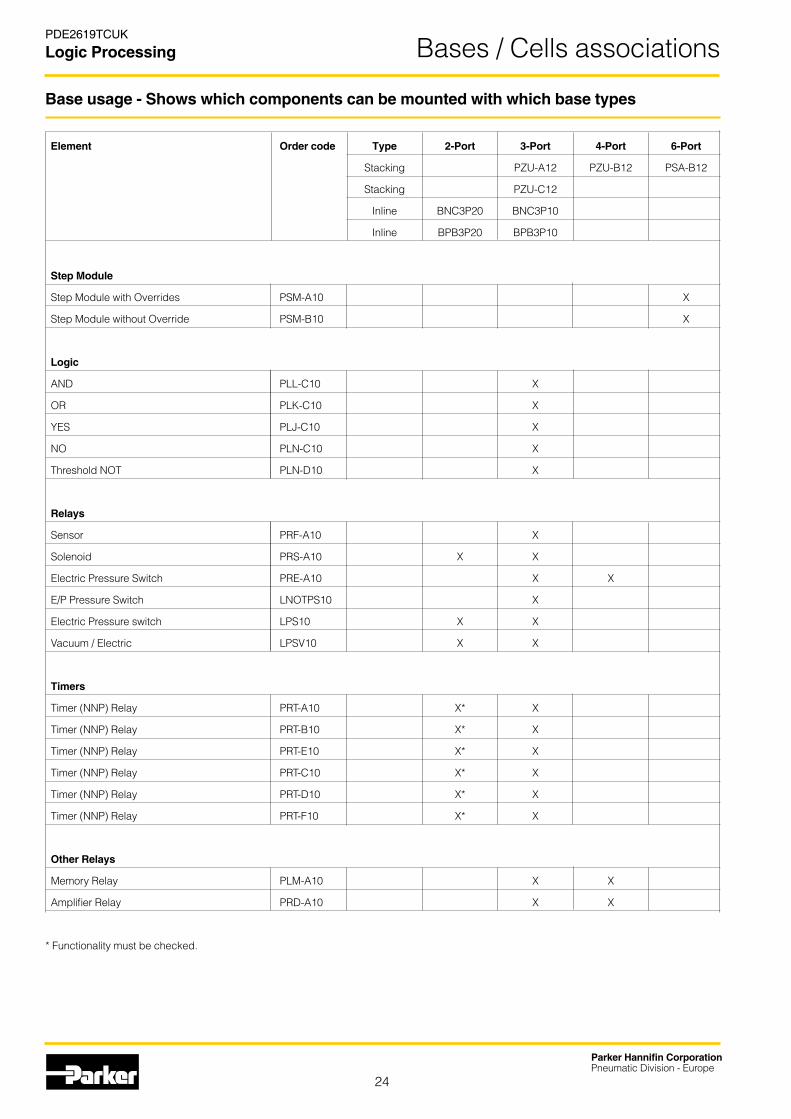
Element Order code Type 2-Port 3-Port 4-Port 6-Port
Stacking PZU-A12 PZU-B12 PSA-B12
Stacking PZU-C12
Inline BNC3P20 BNC3P10
Inline BPB3P20 BPB3P10
Step Module
Step Module with Overrides PSM-A10 X
Step Module without Override PSM-B10 X
Logic
AND PLL-C10 X
OR PLK-C10 X
YES PLJ-C10 X
NO PLN-C10 X
Threshold NOT PLN-D10 X
Relays
Sensor PRF-A10 X
Solenoid PRS-A10 X X
Electric Pressure Switch PRE-A10 X X
E/P Pressure Switch LNOTPS10 X
Electric Pressure switch LPS10 X X
Vacuum / Electric LPSV10 X X
Timers
Timer (NNP) Relay PRT-A10 X* X
Timer (NNP) Relay PRT-B10 X* X
Timer (NNP) Relay PRT-E10 X* X
Timer (NNP) Relay PRT-C10 X* X
Timer (NNP) Relay PRT-D10 X* X
Timer (NNP) Relay PRT-F10 X* X
Other Relays
Memory Relay PLM-A10 X X
Amplifier Relay PRD-A10 X X
* Functionality must be checked.
Base usage - Shows which components can be mounted with which base types
Bases / Cells associations

25
Parker Hannifin CorporationPneumatic Division - Europe
PDE2619TCUK
Logic Processing
Port Label Color
Supply P 2 Black / None
Signal a 1 Green
Output S 3 Red
Entry Module Head / Tail
PZU-E12 PSE-A12 *
PZU-A12 PSB-A12 **
PZU-C12
PZU-B12
Used with
Base
Fitting color code
Sequencer input power modules
Bases / Cells associations
* PSE-A12-EX (ATEX version)
* PSE-A127 (U.S. version)
** PSB-A12-EX (ATEX version)

26
Parker Hannifin CorporationPneumatic Division - Europe
PDE2619TCUK
Logic Processing
Dimensions, Logic processing
Modular sequencer
Line mounted logic elements PLL-A11 and PLK-A11
Combinable logic elementsPLE-B12 — PLL-B12 — PLK-B12 and PLN-B12
Logic elements mounted on 3-port modular sub-basesPZU-E12 PLJ-C10 — PLN-C10 — PLK-C10 and PLL-C10 mounted on PZU-C12 and PZU-A12
Ø6 mm push-in connections Ø4 mm push-in connections
DIN rail
DIN rail
55 44
1414
1455
R B
P A
B
A
B
A
R
B
A
3235,5 44 3244 25,5
14
PSM-A12
PSD-A12 PSD-B12
55
48,52215
70,5
PSE-A12 PSM-A10
55
48,52215
97,5
PSE-A12 PSM-A10
27
PSV-A10
vis M4
12
1
35
Ø4,2
22 16 16
PZM-L199
16
Pressure indicator
Ø4 mm push-in connections
22
7
14
2215
1414
Clip
4028
8
1& &
Ø4,2 22 22 26 6,5 6
32
1414
40
25
& 1 &
23 34 34
3022
PLJ-C10
34 34
28
PLN-C10
PLK-C10
PLL-C10
PZU-E12
PZU-C12
PZU-C12
PZU-A12
PZU-A12
Dimensions

27
Parker Hannifin CorporationPneumatic Division - Europe
PDE2619TCUK
Logic Processing
3 and 4-port modular sub-basesPZU-E12 — PZU-C12 — PZU-A12 PZU-B12
Relays mounted on 3-port modular sub-basesPRT-A12 — PRF-A12 — PRE-A12 — PRS-A121 and PLN-D12
Relays mounted on 4-port modular sub-basesPLM-A12 and PRD-A12
Pressure switchPS1-P1091
Ø3 mm adjusting screw
DIN rail
DIN rail
38
12
305
25Ø4,2
2215
1414
Clip
40
30
10
23
15
Ø4,2
34 34
1414
40
10
4014
14
33 25
28
32
2215
34
9722
34343434
28 30
5465
PRT-A12 PRF-A12 PRE-A12 PRS-A121. PLN-D12
4014
14
3838
4922
43
17,517,517,5 40,5
77,5
n. modules
Dimensions

28
Parker Hannifin CorporationPneumatic Division - Europe
PDE2619TCUK
Logic Processing
Totalising countersPCT-A11 PCT-B11
Preselection countersPCP-A11 and PCP-S11
Binary countersPCM-A11 and PCM-B11
2XØ4,5
==
23
== 32
Z Y
P A
==
51
62,513,5
32,5 ==
60
==
62,5
75
Connexions instantanées Ø4 mmØ4 mm push-in connections
==
90
27
16 ==
53
==
80 100
38 ==
3XØ4
Z Y
== 32
==
(1) Connexionsinstantanées Ø4 mm
==
26
62,59
32,5 == 50
==
60
38 50
2XØ4,5
Ø4 mm push-in connections
Dimensions
.177 (4.5) Dia.4 Places
ExhaustBreather
1/4" Port5 Places
.177 (4.5) Dia.4 Places
ExhaustBreather
1/4" Port5 Places
2147900 2147950

29
Parker Hannifin CorporationPneumatic Division - Europe
PDE2619TCUK
Logic Processing
60
58,6
3,9
12 max.
2,5 7,8
58,6
1611,5
21,8
10,4
Connexions instantanées Ø 4 mm
48
27,2
24
Digital display timersPCM-A11 and PCM-B11
Timers with calibrated dialPCM-F11 and PCM-G11
Ø4 mm push-in connections
Dimensions
2XØ4,5=
=23
== 32
X Y
P A
==
51
115,513,5
32,5 48 ==
60
==
62,5
75 51
==
4622=
=
==
Ø4 mm push-in connections
30
Parker Hannifin CorporationPneumatic Division - Europe
PDE2619TCUK
Logic Processing

31
Parker Hannifin CorporationPneumatic Division - Europe
PDE2619TCUK
Logic Processing

AE – UAE, DubaiTel: +971 4 8127100 [email protected]
AR – Argentina, Buenos AiresTel: +54 3327 44 4129
AT – Austria, Wiener NeustadtTel: +43 (0)2622 23501-0 [email protected]
AT – Eastern Europe, Wiener Neustadt Tel: +43 (0)2622 23501 900 [email protected]
AU – Australia, Castle HillTel: +61 (0)2-9634 7777
AZ – Azerbaijan, BakuTel: +994 50 2233 458 [email protected]
BE/LU – Belgium, NivellesTel: +32 (0)67 280 900 [email protected]
BR – Brazil, Cachoeirinha RSTel: +55 51 3470 9144
BY – Belarus, MinskTel: +375 17 209 9399 [email protected]
CA – Canada, Milton, OntarioTel: +1 905 693 3000
CH – Switzerland, EtoyTel: +41 (0) 21 821 02 30 [email protected]
CL – Chile, SantiagoTel: +56 2 623 1216
CN – China, ShanghaiTel: +86 21 2899 5000
CZ – Czech Republic, KlecanyTel: +420 284 083 111 [email protected]
DE – Germany, KaarstTel: +49 (0)2131 4016 0 [email protected]
DK – Denmark, BallerupTel: +45 43 56 04 00 [email protected]
ES – Spain, MadridTel: +34 902 330 001 [email protected]
FI – Finland, VantaaTel: +358 (0)20 753 2500 [email protected]
FR – France, Contamine s/ArveTel: +33 (0)4 50 25 80 25 [email protected]
GR – Greece, AthensTel: +30 210 933 6450 [email protected]
HK – Hong Kong Tel: +852 2428 8008
HU – Hungary, BudapestTel: +36 1 220 4155 [email protected]
IE – Ireland, DublinTel: +353 (0)1 466 6370 [email protected]
IN – India, MumbaiTel: +91 22 6513 7081-85
IT – Italy, Corsico (MI)Tel: +39 02 45 19 21 [email protected]
JP – Japan, TokyoTel: +(81) 3 6408 3901
KR – South Korea, SeoulTel: +82 2 559 0400
KZ – Kazakhstan, AlmatyTel: +7 7272 505 800 [email protected]
LV – Latvia, RigaTel: +371 6 745 2601 [email protected]
MX – Mexico, ApodacaTel: +52 81 8156 6000
MY – Malaysia, Shah AlamTel: +60 3 7849 0800
NL – The Netherlands, Oldenzaal Tel: +31 (0)541 585 000 [email protected]
NO – Norway, SkiTel: +47 64 91 10 00 [email protected]
NZ – New Zealand, Mt WellingtonTel: +64 9 574 1744
PL – Poland, WarsawTel: +48 (0)22 573 24 00 [email protected]
PT – Portugal, Leca da PalmeiraTel: +351 22 999 7360 [email protected]
RO – Romania, BucharestTel: +40 21 252 1382 [email protected]
RU – Russia, MoscowTel: +7 495 645-2156 [email protected]
SE – Sweden, SpångaTel: +46 (0)8 59 79 50 00 [email protected]
SG – Singapore Tel: +65 6887 6300
SK – Slovakia, Banská BystricaTel: +421 484 162 252 [email protected]
SL – Slovenia, Novo MestoTel: +386 7 337 6650 [email protected]
TH – Thailand, BangkokTel: +662 717 8140
TR – Turkey, IstanbulTel: +90 216 4997081 [email protected]
TW – Taiwan, TaipeiTel: +886 2 2298 8987
UA – Ukraine, KievTel +380 44 494 2731 [email protected]
UK – United Kingdom, Warwick Tel: +44 (0)1926 317 878 [email protected]
US – USA, Cleveland Tel: +1 216 896 3000
VE – Venezuela, CaracasTel: +58 212 238 5422
ZA – South Africa, Kempton Park Tel: +27 (0)11 961 0700 [email protected]
Catalogue PDE2619TCUK October 2009
Your local authorized Parker distributor
© 2009 Parker Hannifin Corporation. All rights reserved.
Parker Worldwide
European Product Information CentreFree phone: 00 800 27 27 5374(from AT, BE, CH, CZ, DE, DK, EE, ES, FI, FR, IE, IL, IS, IT, LU, MT, NL, NO, PL, PT, RU, SE, UK, ZA)
Parker Hannifin LtdPneumatic Division EuropeThe Collins Centre,Lichfield South, Wall Island,Birmingham Road, Lichfield.WS14 0QP United KingdomTel.: +44 (0) 1543 483800Fax: +44 (0) 1543 483801www.parker.com/euro_pneumatic