logic applications - · pdf file7/2/2017 · history of logic circuits ... attention...
TRANSCRIPT

LOGIC APPLICATIONS

DIGITAL LOGIC CIRCUITS
• Noticed an analogy between the operations of switching devices, such as telephone switching circuits, and the operations of logical connectives
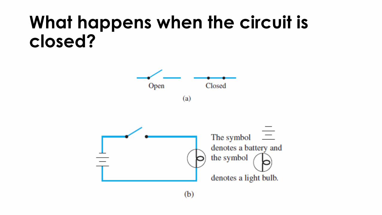
What happens when the circuit is closed?
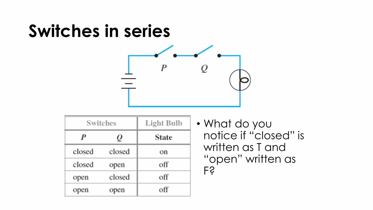
Switches in series
• What do you notice if “closed” is written as T and “open” written as F?

Switches in parallel
• What do you notice if “closed” is written as T and “open” written as F?

HISTORY OF LOGIC CIRCUITS
• In the 1940s and 1950s, switches were replaced by electronic devices
• The new electronic technology led to the development of modern digital systems such as electronic computers, electronic telephone switching systems, traffic light controls, electronic calculators, etc.
• The basic electronic components of a digital system are called digital logic circuits.

1’s and 0’s
• Electrical engineers continue to use the language of logic when they refer to values of signals produced by an electronic switch as being “true” or “false.”
• But they generally use the symbols 1 and 0 rather than T and F to denote these values.
• The symbols 0 and 1 are called bits, short for binary digits.
Black Boxes and Gates
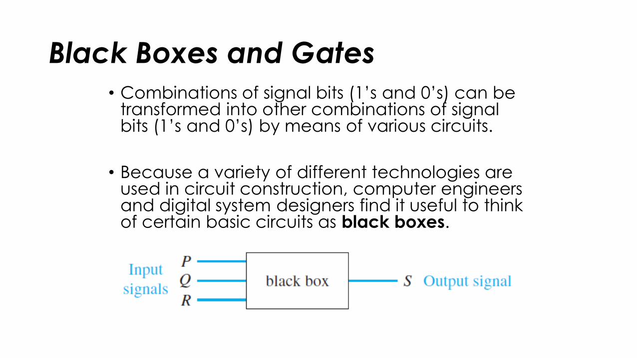
• Combinations of signal bits (1’s and 0’s) can be transformed into other combinations of signal bits (1’s and 0’s) by means of various circuits.
• Because a variety of different technologies are used in circuit construction, computer engineers and digital system designers find it useful to think of certain basic circuits as black boxes.
Black Boxes and Gates
• The inside of a black box contains the detailed implementation of the circuit and is often ignored while attention is focused on the relation between the input and the output signals.
• An efficient method for designing more complicated circuits is to build them by connecting less complicated black box circuits. Three such circuits are known as NOT-, AND-, and OR-gates.

NOT-gate
• A NOT-gate (or inverter) is a circuit with one input signal and one output signal. If the input signal is 1, the output signal is 0. Conversely, if the input signal is 0, then the output signal is 1.
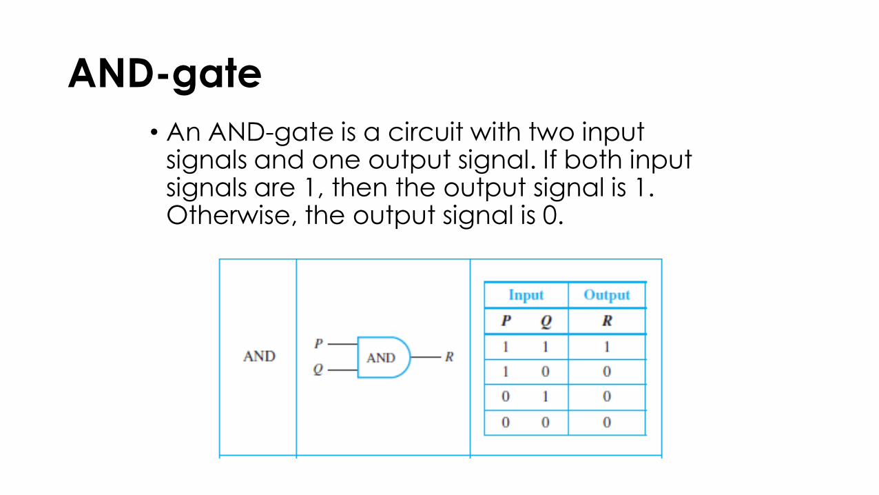
AND-gate
• An AND-gate is a circuit with two input signals and one output signal. If both input signals are 1, then the output signal is 1. Otherwise, the output signal is 0.

OR-gate
• An OR-gate also has two input signals and one output signal. If both input signals are 0, then the output signal is 0. Otherwise, the output signal is 1.

COMBINATIONAL CIRCUIT
• Gates can be combined into circuits in a variety of ways.
• The result is a combinational circuit, one whose output at any time is determined entirely by its input at that time without regard to previous inputs.
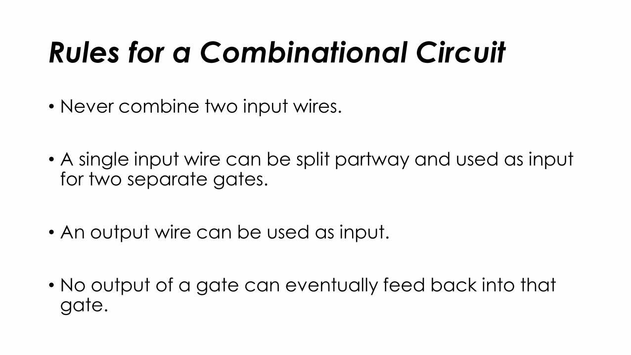
Rules for a Combinational Circuit
• Never combine two input wires.
• A single input wire can be split partway and used as input for two separate gates.
• An output wire can be used as input.
• No output of a gate can eventually feed back into that gate.

The I/O Table for a Circuit
• If you are given a set of input signals for a circuit, you can find its output by tracing through the circuit gate by gate.
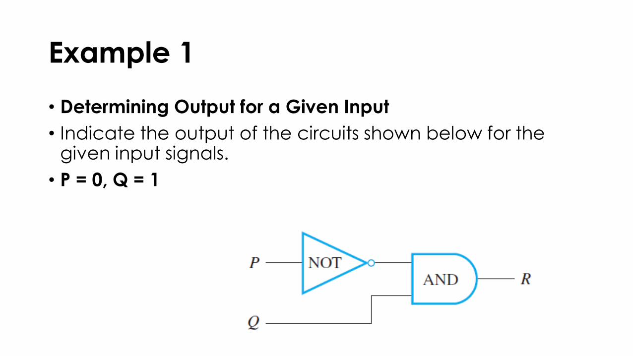
Example 1
• Determining Output for a Given Input
• Indicate the output of the circuits shown below for the given input signals.
• P = 0, Q = 1
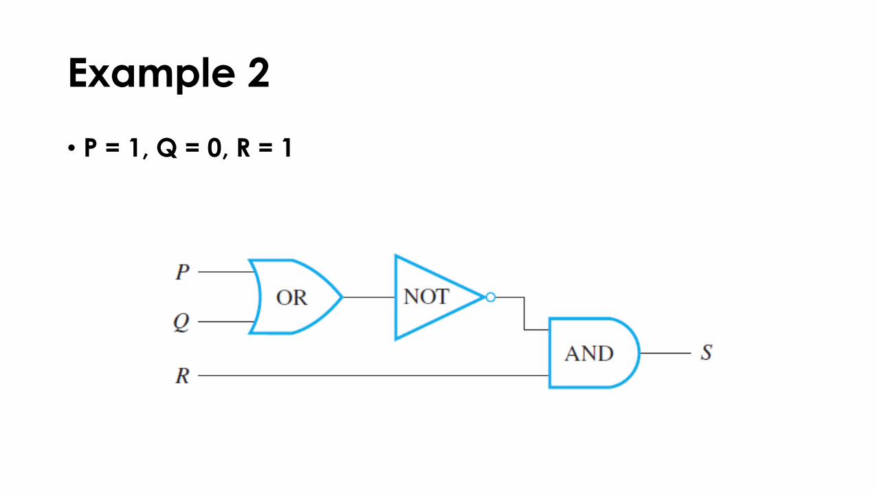
Example 2
• P = 1, Q = 0, R = 1

Constructing the Input/Output Table for a Circuit• Construct the input/output table for the following circuit.

The Boolean Expression Corresponding to a Circuit• In logic, variables such as p, q and r represent statements,
and a statement can have one of only two truth values: T (true) or F (false).
• A statement form is an expression, such as p ∧ (∼q ∨ r ), composed of statement variables and logical connectives.
• One of the founders of symbolic logic was the English mathematician George Boole.
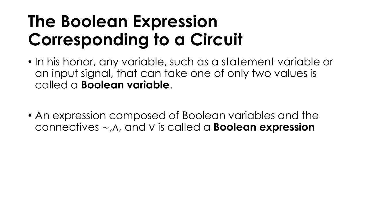
The Boolean Expression Corresponding to a Circuit• In his honor, any variable, such as a statement variable or
an input signal, that can take one of only two values is called a Boolean variable.
• An expression composed of Boolean variables and the connectives ∼,∧, and ∨ is called a Boolean expression
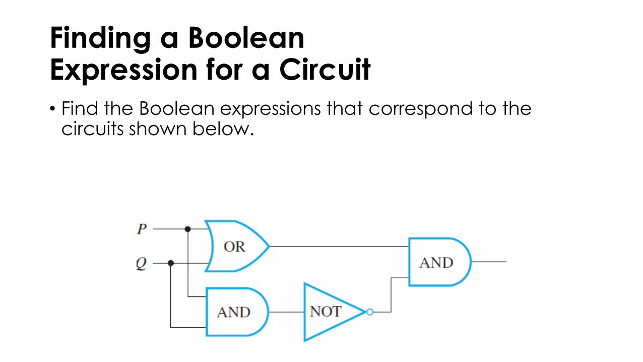
Finding a Boolean Expression for a Circuit• Find the Boolean expressions that correspond to the
circuits shown below.
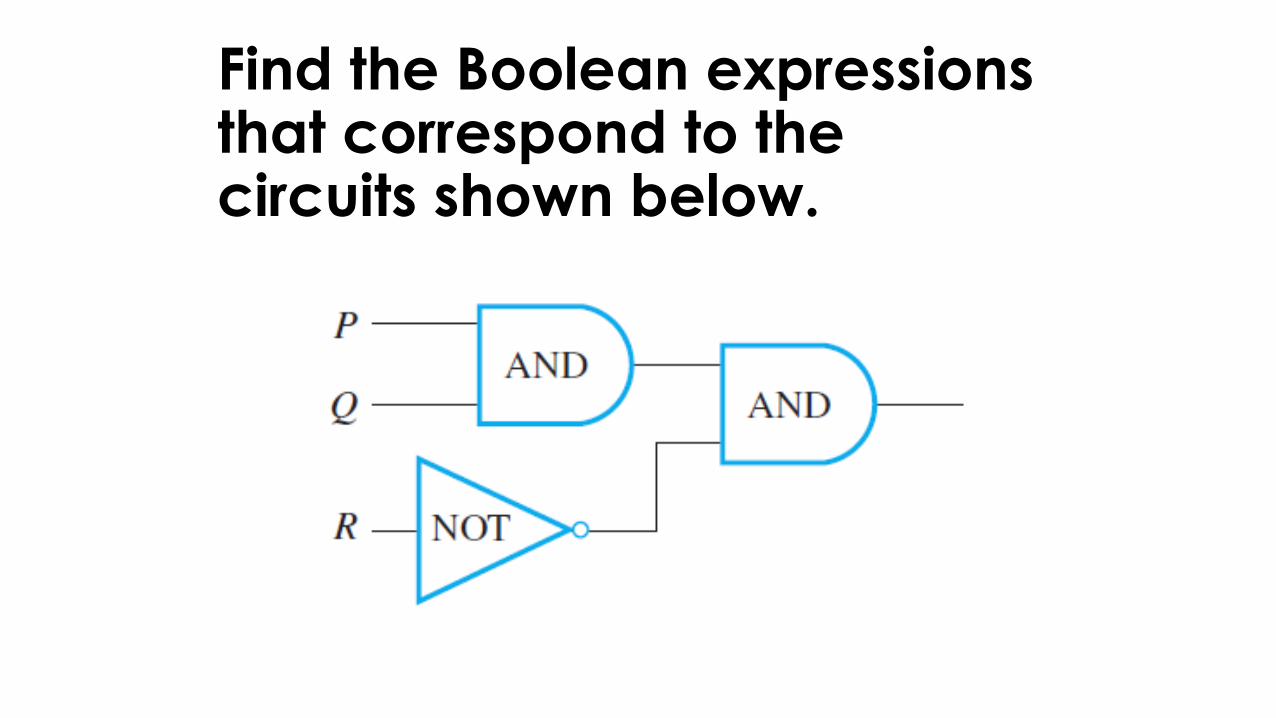
Find the Boolean expressions that correspond to the circuits shown below.