locomotives p ^pioneer" - smithsonian institution libraries
TRANSCRIPT

Y Y ' : : -• :' "•'••'
^ Y ^ Y ^ Y Y ••••. ...;•.:v-v'-.-. 1
. , . •
\meri4i Locomotives p ^Pioneer"
John H. White. Jr.


American Single Locomotives and the **Piomeer93
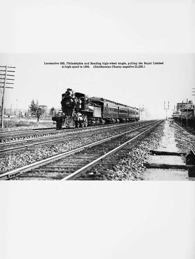
=fc Locomotive 385, Philadelphia and Reading high-wheel single, pulling the Royal Limited
at high speed in 1896. (Smithsonian Chaney negative 21,525.)

SMITHSONIAN STUDIES IN HISTORY AND TECHNOLOGY j NUMBER 25
American Single Locomotives and the ^Pioneer"
John H. White. Jr<
SMITHSONIAN INSTITUTION PRESS / CITY OF WASH INGTON / 1973

S E R I A L P U B L I C A T I O N S OF T H E S M I T H S O N I A N I N S T I T U T I O N
The emphasis upon publications as a means of diffusing knowledge was expressed by the first Secretary of the Smithsonian Institution. In his formal plan for the Institution, Joseph Henry articulated a program that included the following statement: "I t is proposed to publish a scries of reports, giving an account of the new discoveries in science, and of the changes made from year to year in all branches of knowledge." This keynote of basic research has been adhered to over the years in the issuance of thousands of titles in serial publications under the Smithsonian imprint, commencing with Smithsonian Contributions to Knowledge in 1848 and continuing with the following active series:
Smithsonian Annals of Flight
Smithsonian Contributions to Anthropology
Smithsonian Contributions to Astrophysics
Smithsonian Contributions to Botany
Smithsonian Contributions to the Earth Sciences
Smithsonian Contributions to Paleobiology
Smithsonian Contributions to Zoology
Smithsonian Studies in History and Technology
In these series, the Institution publishes original articles and monographs dealing with the research and collections of its several museums and offices and of professional colleagues at other institutions of learning. These papers report newly acquired facts, synoptic interpretations of data, or original theory in specialized fields. These publications are distributed by mailing lists to libraries, laboratories, and other interested institutions and specialists throughout the world. Individual copies may be obtained from the Smithsonian Institution Press as long as stocks are available.
S. DILLON RIPLEY
Secretary Smithsonian Institution
OFFICIAL PUBLICATION DATE is handstamped in a limited number of initial copies and is recorded in the Institution's annual report, Smithsonian Year. SI PRESS NUMBER 4794.
Library of Congress Cataloging in Publication Data White, John H., Jr . American single locomotives and the Pioneer. (Smithsonian studies in history and technology, no. 25) 1. Locomotives—United States—History. I. Title. II. Series: Smithsonian studies in
history and technology, no. 25. TJ603.2.W48 625.2'61'0973 73-1062
For sale by the Superintendent of Documents, U.S. Government Printing Office Washington, D.C. 20402 - Price: 95 cents, domestic postpaid; 70 cents, GPO Bookstore
Stock Number 4700-00256
iv

Contents
Page
The American Single Locomotive 1 The Pioneer 21
The Cumberland Valley Railroad 23 Service History 27 Mechanical Description 27
Boiler 27 Boiler Fittings 37 Frame 41 Running Gear 44 Valve Gear 45 Miscellaneous Notes 47
Notes 48

American Single Locomotives and the ^Pioneer93
John H. White. Jr.
In the mid-nineteenth century there was a renewed interest in the light, single-axle locomotives which were proving so very successful for passenger traffic. These engines were built in limited number by nearly every well-known maker, and among the few remaining is the six-wheel Pioneer, on display in the Smithsonian Institution's National Museum of History and Technology. This locomotive is a true representation of a light passenger locomotive of 1851 and a historic relic of the mid-nineteenth century.
The Author: John H. White, Jr., is the curator of transportation in the Smithsonian Institution's National Museum of History and Technology.
The American Single Locomotive
Until the early or even the mid-1840s locomotives with a single pair of driving wheels were considered suitable for ordinary service on American railroads. After that time, however, engines of greater tractive power were deemed necessary to economically propel trains on our curving, hilly lines. Many single-driving axle machines were remodeled with an additional pair of drivers, while others were retired at an early date. The six-wheel, truck or Jervis type of locomotive (4-2-0) that seemed destined to become the standard American locomotive prevailed for less than a decade and was thought
obsolete by 1845.x After that time, the "single" became something of a freak on North American railroads. Those that were produced later in the nineteenth century were either for very light passenger service, such as the Pioneer, or extraordinary high wheelers meant for the fastest express trains.
The eight wheel (4-4-0) or American type was a logical enlargement of the 4-2-0. The modest cost and trouble in adding a second pair of driving wheels and only a small enlargement of boiler and cylinders, resulted in a remarkable improvement in pulling power, often over sixty

VflliUA SMITHSONIAN STUDIES IN HISTORY AND TECHNOLOGY
a
FIGURE 1. At first, the single-driver Jervis type seemed destined to dominate the American railroad scene, but its reign (about 1835-1842) was cut short by the more powerful American type. Shown here is a Norris, Jervis type of about 1837.
percent.2 The stability and good riding qualities of the 4-4-0 over the 4-2-0 were also notable. Hence, it is little wonder that the six-wheel truck engine was displaced. Its early defeat was to forever condemn the single-axle locomotive to the most remote marches of American locomotive practice.
In Great Britain and continental Europe, however, the single enjoyed a continued popularity as the standard passenger locomotive, and this form of railway engine was widely used in that area of the world until the early years of the present century when it suffered a sudden decline. To explain these widely differing preferences in this short study is not possible, but it can be suggested that contrasting operating conditions (level and straight versus rolling and crooked lines) and the engineering prejudices of the overseas mechanical managers were in large part accountable for the acceptance or rejection
of the single. Yankee engineers thought singles were slippery and underpowered, while their European counterparts held them to be swift and elegant, the perfect form of express power.
The imaginative plan of a British engineer named Thomas R. Crampton for a high-speed, single-axle locomotive rekindled interest in such machines in North America. Crampton felt that a low-slung boiler with the driving wheel behind the firebox was an essential reform for passenger locomotive design. He claimed that engines on his plan would lower the center of gravity, permit a wider firebox and steady the engine's running by avoiding overhanging masses at either end. A patent was issued in 1842, but most British lines were singularly disinterested. Four years later, a Crampton was built for a Belgian line and a few machines were later produced for several British railways. One of the first of these is illustrated in Figure 3. German and

NUMBER 25
c g —
FIGURE 2. Successor to the single and longtime champion of the American railway for freight and passenger service was the eight wheel, 4—4-0. Baldwin built the example shown here in about 1845.
FIGURE 3. The Kinnaird was a high-wheeled (84 inches) Crampton locomotive built in 1848 by Tulk & Ley for the Dundee and Perth Railway. (Photograph courtesy of R. E. Bleasdale.)
494-500 O - 73 - 2

SMITHSONIAN STUDIES IN HISTORY AND TECHNOLOGY
French mechanics, however, developed a marked passion for the Crampton and some three hundred were built for continental service before 1865.
In the mid-1840s Robert L. Stevens, president of the Camden and Amboy Railroad and something of a mechanic himself, visited England and recognized the potential of the high-wheeled single for his level New Jersey railroad.3 Talk of Crampton's design was very much in the press, if not in the drawing office, at the time of Stevens' visit and so the plan was adopted, with some modifications, by the Camden and Amboy. The first locomotive was completed by Norris
Brothers of Philadelphia in April 1849. Six sister machines followed during the next four years (Figure 4). All except the first were distinguished by giant 96-inch wheels. They had a wonderful capacity for speed, but were woefully deficient in tractive force and had great difficulty in starting even the light trains of that period. All but one had been remodeled as a 4-4-0 by 1857.
That they were a success or failure had nothing to do with it. The very existence of these startling machines prompted the production of several other American high-wheel singles. Baldwin hurriedly built an Americanized
FIGURE 4. An American Crampton was the Camden and Amboy's extraordinary No. 30, built by Norris Brothers in 1850. This photograph was made sometime before the engine was remodeled in 1856 and is one of the earliest surviving camera views of an American locomotive known to exist. (Smithsonian Chaney negative 2455.)

NUMBER 25
Crampton named the Mifflin for the Pennsylvania Railroad in July 1849. It was followed by two near duplicates which, like the Mifflin, only served to prove the folly of a single pair of driving wheels for a mountainous railway.
A more congenial proving ground for the single express was present in the nearly level Hudson River Railroad that followed the gentle curves of that mighty stream along its eastern bank. Thomas Rogers of Paterson, New Jersey, built a single for the line in 1849, the Baldwin Locomotive Works followed with a second machine the next year. The wheels were only moderately high (72 inches), but again a lack of adhesion proved their undoing. The Baldwin engine was reportedly returned to its maker. Rogers' pet was rebuilt as a 4-4-0.
Ross Winans, machinist and locomotive builder of Baltimore, was certain he had a solution for the slippery single. An undoubted mechanical genius, Winans' career was illuminated by a series of engineering anomalies, not all of which can fairly be credited as being successful. Independent, cranky, and filled with the zeal of the true believer, Winans was willing to pay the price for his views. He was jailed briefly at the beginning of the Civil War and would have been hanged by General Benjamin Franklin Butler for his overt southern sympathies had not the War Department intervened. His entanglements with experimental locomotives were perhaps less dramatic, but they did manage to consume a portion of his fortune. One of the biggest losers surely was the ill-fated Carroll of Carrollton.4
It all began innocently enough. The Boston and Worcester Railroad wanted to experiment with coal-burning passenger locomotives and knowing of Winans' prominence in the area of coal-burning freight locomotives, turned to him in 1847 for a design. The result of that inquiry was an astonishingly large and ungainly camel-back locomotive with a single pair of 84-inch driving wheels (Figure 5) which Winans chose to name for a famous old Baltimore resident, Charles Carroll of Carrollton, renowned before his death in 1832 as the last surviving signer of the Declaration of Independence.
The Carroll was delivered to Boston in the fall of 1849. The initial road tests were gratifying; she easily attained 60 mph though the speed could be maintained only for a short distance
FIGURE 5. The patent model for Ross Winans' steam spring (Patent No. 8571, December 2, 1851) is in the Smithsonian's collection. A full-size locomotive, the Carroll of Carrollton, which incorporated the main features of the patent was completed two years before the patent was issued. (Smithsonian negative 65463.)
because the roadbed was not adequate for such fast running.
The poor starting qualities of the single were said to be overcome by Winans' ingenious "steam spring" mounted over the driving-axle boxes. They could transfer as much as 12!/2 tons to the drivers for greater adhesion. Actually, the steam spring was an old idea, but no matter, Winans did use it to good advantage and claimed to have thus solved the single's great failing. In truth, the steam spring proved the Carroll's undoing; after only two months of service both drivers were broken because of the undue weight thrust upon them. It was also reported that the drivers slipped, even when under the utmost pressure the springs could exert. New wheels were sent to Boston. Winans alternately cajoled and threatened the Boston and Worcester to accept the engine, but they successfully resisted his entreaties; the Carroll, thoroughly humiliated, was sent home aboard a coastal vessel. She was tucked away in a back corner of Winans' shop awaiting a buyer who was never to appear.
The high-wheeled singles failed to win more than the passing interest of American railroad

SMITHSONIAN STUDIES IN HISTORY AND TECHNOLOGY
managers in the first two or three decades of the industry's history. Several other experimental engines were built before the middle 1850s, but no practical railroader would accept them for regular service. A new generation was coming into power, however, and some of these younger men were undoubtedly impressed by the good service of singles on foreign lines (Figure 6). Old ideas thus find new champions and the discredited schemes of the past are reborn, but in this instance only to be discredited once again.
It started again in the late 1870s when the Philadelphia and Reading decided it needed an express engine for its newly leased Bound Brook Line which ran from Philadelphia to Jersey City. The road's dynamic president, Franklin B. Gowan, knew the value of publicity and indicated that something flashy and unusual should be used to capture public attention. The details of the design were left to the Baldwin's mechanical superintendent William P. Henszey.
Henszey revived the Winans steam-spring idea, but modified the old plan so that the steam cylinder acted on the equalizing levers between the driving- and trailing-wheel axles so that more or less weight could be thrown on the drivers as desired. The design was the subject of Patent No. 227,778 of May 18, 1880. The Baldwin factory was so pleased with the prospects of the new 42.5 ton engine that even a construction number—the 5000—was assigned to it. The Reading gave her the road number 507. On May 14, 1880, a test run was made between Philadelphia and Jersey City (89 miles) with a four-car train weighing 84 tons. She performed admirably averaging 54.7 mph and on occasions sailed along at over 80 mph. A great future for high-wheeled singles was envisioned, express trains were beginning to make an appearance on American railways, and the need for faster motive power was obvious. Champions of the single argued that it was not only
FIGURE 6. British railways remained loyal to high-speed singles long after America had abandoned them. Shown here is the Bristol and Exeter Railway's 2002, a 7-foot-gauge engine of noble proportions. Three sister engines were produced in 1868; all were retired by 1890. (Photograph courtesy of R. E. Bleasdale.)
. 4*
vi

NUMBER 25
faster and cheaper, but safer than ordinary coupled locomotives because the side rods and "auxiliary" wheels were eliminated. At high speeds the danger of breaking side rods was a hazard, but a far less likely eventuality than the single advocates would care to admit. Yet, it was another justification for overthrowing the standard eight wheeler. A better argument was the more perfect balance that was made possible by eliminating the side rods; this was an important consideration at high speeds.
An unexpected turn of events, however, abruptly ended the 5000's career on the Bound Brook Line. Within days of the trial run, Gow-an's empire collapsed. The failure of the Reading was as unexpected and catastrophic as the bankruptcy of the Penn Central in recent years. Creditors appeared from all sides taking away whatever property was not encumbered. Among these parties was the Baldwin Locomotive Works which withdrew three new locomotives
that had not been formally delivered. One of these was the 5000. Buyers were quickly found for two conventional freight locomotives, but the 5000 proved less salable and seemed destined to follow the sad example of the Carroll of Carrollton. Much to the relief of the Baldwin, Frederick W. Eames, patentee of a vacuum brake, took a liking to the orphaned high wheeler. He needed a demonstrator to show off his brake in England. The 5000 was perfect, she would be well received by British railway men who already favored singles and would like to see a Yankee version of their standard form of express engine. It is also likely that the Baldwin Locomotive Works was ready to let her go cheaply. Eames not only had her outfitted with his brake, but had her smartly refinished. She was named in honor of his father: Lovett Eames.5 His portrait was attached to the center panel of the cab, while a scenic view of Black River Falls and the nearby vacuum-brake plant
FIGURE 7. The Lovett Eames, the five-thousandth locomotive produced by the Baldwin Locomotive Works, was originally built in 1880 for the Philadelphia and Reading Railroad. She was repossessed by the builder and sold to the Eames Vacuum Brake Company to demonstrate that firm's apparatus. (Smithsonian negative 26802-B.)

8 SMITHSONIAN STUDIES IN HISTORY AND TECHNOLOGY
at Watertown, New York, was painted in a medallion on the tender's side (Figure 7).
Reports of the English brake trials appeared in the October 14, 1881, issue of Engineer. The following August, the Eames was reported on display at the Alexandria Palace, near London, as part of the Exhibition of Life Saving Appliances. Sometime during her English running days, it was found necessary to lower her overall profile to suit the small loading gauges typical of the British lines. The cab roof was lowered and the sides given a rakish curve; the stack was cut down, and the headlight and its mounting bracket were dropped (Figure 8).
Eames failed to market his brake beyond a few token installations and appears to have abandoned the engine. In April 1884, advertisements appeared in the British trade press announcing a court-ordered sale of the Lovett Eames. The only interested bidder was a scrap merchant who for $900 took her away to Wood Green where she was broken up as so much old iron. Here ends the story of this vagabond
among locomotives except for one detail. The bell was salvaged for use at an engine house of the Great Northern Railway. In 1938 it passed into the hands of an American locomotive enthusiast named Richard E. Pennoyer, and in recent years it was presented to the Science Museum in London. It may be seen today in the Railway Gallery of that renowned institution.
Fifteen years after the 5000's fiasco, the Philadelphia and Reading was ready again to try a high-speed single, and again William Henszey was to have a hand in its design.6 By this time, 1895, the high-wheel bicycle craze was at its peak and the new engine's resemblance prompted the term "bicycle locomotive"; but the engine was anything but a featherweight bicycle. She was a giantess among singles and at 57!/2 tons was probably the largest locomotive of her type ever built. The 84*4-inch-diameter drivers were driven by compound cylinders on the Vauclain plan (Figure 9).
Two engines were built on this design by Baldwin. The first, No. 385, was delivered in
FIGURE 8. The Lovett Eames as remodeled for service in Great Britain. The engine was scrapped in 1884. (Photograph courtesy of R. E. Bleasdale.)

NUMBER 25
1895; the second, No. 378, was completed the following year. The editor of Locomotive Engineering (1895) was invited to ride the 385 soon after she entered service, and a portion of Angus Sinclair's colorful report in the journal is quoted below.
When I was invited by Mr. S. M. Vauclain to take a ride on the new Philadelphia & Reading single-driver engine, I very readily accepted the offer for the "days of auld lang syne." On getting to Jersey City, where I found the engine already attached to a six-car train of the heavy Blue Line, I looked at the load and examined the engine, and felt, from past experience, that there would be some difficulty in getting the train into speed. The old-time single-driver engines would run, once they got the train going, but they were very slow on the start.
The engine attracted great attention. Crowds of people stood round watching the latest curiosity, and from the remarks heard on the platform, the belief prevailed that she was a hybrid between a locomotive and an electric motor.
The cars weighed at the least estimate about 120 tons. When the starting time came I climbed up into the cab on the top of the boiler. The engineer had everything ready, and when the signal was given, pulled out without slip or jerk. This is made possible by use of the air sanding device. There is a long yard to be traversed in the start, and the presumption is that the maximum speed was not attempted there; but the engine covered
the first six miles in seven and a half minutes. That settled in my mind the question about single-driver engines being slow in starting.
After I had ceased watching the mile posts to make sure of the speed, I settled down to watch the working of the engine. The first impression received was: "How splendidly she rides!" A train of six heavy parlor cars is not kept moving at a speed of 60 miles an hour without great expenditure of power. The easy maintenance of speed with this engine was due in a great measure to the fine steaming qualities. All throughout the run of 92 miles, the steam gage showed a constant pressure close on the popping point of 200 pounds to the square inch. This was the more surprising, considering the character of the coal. I examined it carefully on the tender, and found it to be anthracite slack—not the clean, grain-looking coal known as pea, but a mixture of pea and dust. The Wootten firebox, with its large grate area, makes the burning of such coal a possibility on a highspeed locomotive. With the ordinary firebox and sharp exhaust, this coal would pass through the tubes almost as fast as it could be thrown in; but with this large firebox and the soft exhaust characteristic of a compound locomotive, the finest particles of carbon are utilized to their fullest extent.
The run of 92 miles in two hours and six minutes, with seven stops, ought not to involve exceptionally fast running, since the engineers are instructed to make the speed as nearly uniform as possible. But as we go along through the crowded towns and villages on the route, we soon realize how stretches of speed of about 70 miles an hour or over are necessary to make the time. There is a constant call to slow up at stations where crowds
FIGURE 9. America's final effort to test the single for express service is represented by the Philadelphia and Reading's 385. She was produced by Baldwin in 1895. (Photograph courtesy of Thomas Norrell.)
- : (.'^: •

10 SMITHSONIAN STUDIES IN HISTORY AND TECHNOLOGY
of passengers are loading upon local trains. A system of overhead bridges for passengers to cross the track on, and fences to prevent them from crossing on the level, would aid greatly in maintaining high speed for through trains. The Jersey Central and Philadelphia & Reading have excellent track in the line between New York & Philadelphia, but the facilities for keeping people off the track might be greatly improved. The Pennsylvania Railroad is much better provided in this respect.
We left Jersey City at 6:12 P.M., and had only got over about half the distance when it became dark. Then we could see in its strongest aspect the safety and comfort that comes from the use of block signals. As stations were approached the novice was struck with the confusion of head lights, tail lights, electric lights and all varieties of lights, many of them colored; but the engineer looked for a particular spot, and if the light there did not indicate danger, he kept the train going without hesitation. Rushing along in the front of a train of this kind gives a most impressive lesson of the need for the very best of signals—signals which can make no mistake of indicating safety when the track is blocked by any obstruction.
The train has darted through many junction points, through alleys of cars and through myriads of signals; it has twisted round sharp curves, and screamed through crowded stations. Cuttings and embankments and tunnels have been traversed at the speed of a hurricane, and I realize that the engineer carries a burden of responsibilities that I had never dreamed of, although I had spent twelve years on the footboard. We roll into Philadelphia on time, and I reflect upon making the trip on that engine as the man did who made a meal of crow. It can be done, but one does not hanker after it as a regular thing.
A. S.
They were intended to pull eight-car trains, but the 1.8 percent grade at Fern Rock, Pennsylvania, made it hard going even with a five- or six-car train. Both engines were soon relegated to secondary trains. In 1904 they were rebuilt as eight wheelers and proved serviceable enough in this form to continue in use until the 1930s.
The single was repeatedly discredited in its bid for acceptance as an express locomotive in America. In the early years this was true, mainly because our railways did not attempt to operate high-speed trains. Most lines were cheaply built roads capable of minimal service and entirely unsuited to fast running. Those few American lines that could sustain fast trains preferred high-wheeled eight wheelers which offered superior tractive power in addition to fast running. The later efforts to revive the high-wheeled single in the 1880s and 1890s were at best illusionary and predestined for failure. The heavier wooden cars then in service and the prospect of the steel car insured a not very serious acceptance of any form of locomotive lacking in starting power.
There was, however, another area of railroad operations that the single seemed well suited to serve. Economy-minded railroad managers recognized a need for a very light style of locomotive for accommodation or branch-line passenger trains. What they wanted was a compact model to replace larger motive-power units on secondary trains. One obvious solution was a small, single-driver, tank locomotive. The plentiful supply of surplus 4-2-0s at first met this need nicely. Some were remodeled to more efficiently accomplish their new work. One example of such an ancient rebuilding is shown by the Apponaug (Figure 10). It was built in 1836 by the Locks and Canals machine shop in Lowell, Massachusetts, and is illustrated here after having been remodeled in 1844 with an elongated boiler, the addition of leading and trailing wheels, and other modifications.
Nevertheless, in time, new engines were required. The first of the new breed for which a record can be found was the Vermont Central's Abigail Adams which was completed in June 1847 by the Baldwin Locomotive Works. She was a tiny three-ton tank engine with 42-inch drivers. Unfortunately, no illustrations exist of this machine. It was reported by Zerah Colburn that the managers of the road were disappointed that she couldn't do the work of an ordinary road engine. Their hopes had been raised to such an expectation by reports of very small British locomotives accomplishing such wonders. But as Colburn pointed out, they were of very light construction and had the added ginger of 120-pound steam pressure which was high for the period.7
Baldwin also built three very light engines for the Georgia Railroad in 1846 and 1847, but there is some question as to whether or not they were singles. Again, no pictorial documentation is available.
As an early railroad commuter center, Boston seemed a ripe proving ground for the economy single. Records indicate that George S. Griggs, master mechanic of the Boston and Providence Railroad, was the first to take up the challenge. Two small 2-2-2 tank engines were fabricated at the B&P's Roxbury shops.8
For many years, the suburban trains on its Ded-ham branch had been economically propelled by a handful of aging lightweights dating from the mid 1830s. As these engines came due for major

NUMBER 25 11
FIGURE 10. The New York, Providence and Boston Railroad's Apponaug started life as a "Planet"-type single, 2-2-0, and was remodeled in 1844 as shown in this view at Stonington, Connecticut, about 1875. (Photograph courtesy of Thomas Norrell.)
FIGURE 11. The Boston and Providence Railroad built the Dedham at its Roxbury shops in 1851 for light passenger service. It is shown here after being renamed the Uncle Tom. (Photograph courtesy of the Society for the Preservation of New England Antiquities.)
494-500 O - 73 - 3
12 SMITHSONIAN STUDIES IN HISTORY AND TECHNOLOGY
kttfeftei -- - •
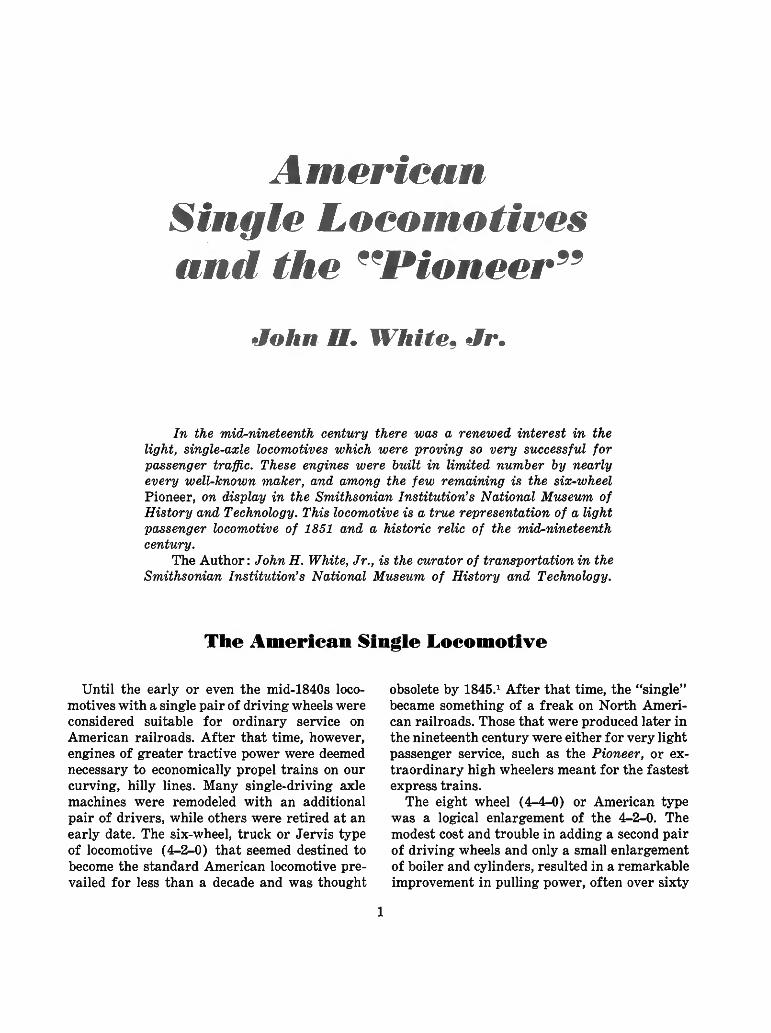
FIGURE 12. The Uncle Tom in its last years, as remodeled and in service on the New York and Flushing Railroad. It is assumed that the photo dates from the 1870s. (Smithsonian negative 22707-L.)
repairs, however, it was considered wise to sell them and, let others invest their hard cash in these obsolete products of Robert Stephenson, Edward Bury, and their contemporaries. Griggs proposed to replace these well-worn engines with two light single tankers. Griggs had already constructed several new locomotives at the Roxbury repair shops, all of which showed no lack of invention. The Dedham and Roxbury completed in the spring of 1851 followed in the same tradition (Figure 11). While Griggs can never fairly be accused of being a mere imitator, he did follow the English preference for cylinders inside of the frames. Most other New England mechanics favored this design—at least before the late 1850s—and both the Dedham and Roxbury were accordingly made. An unusual feature of these engines was the placement of a single large spring across the top of the boiler for the driving axle in place of the usual pair of springs mounted on the frame (Figure 11). Of greater consequence, was Griggs' scheme to improve traction. The rear coupler was attached to a pair of rods which were in turn connected to two L-shaped levers. The levers bore down upon
the driving boxes. Thus, the draft of the train was transferred through the aforementioned arrangement to the driving wheels and the harder the engine pulled and the heavier the train, the greater was the pressure exerted on the drivers. This design was the subject of a patent issued to Griggs in June 1851 (Patent No. 8,166).
In October of 1851, the Dedham was put through public trials at the New England Association of Railway Superintendents convention in Lowell, Massachusetts. She performed superbly and attracted much favorable comment after hauling an 18-ton train of two 8-wheel cars with 81 passengers aboard over a 9-mile course at a speed averaging 42 mph. The judges awarded Griggs a silver medal. More talk was likely generated on the positive merits of the single when combined with Griggs' traction in-creaser, but it soon became clear that the little tankers were another "splendid failure" that simply could not deliver what was expected of them. Both engines were sold. The Roxbury went to the Rome, Watertown and Ogdensburg Railroad, and an uncertain history. The Dedham, renamed Uncle Tom, was sent to the Fitchburg and

NUMBER 25 13
Worcester Railroad where after ten years she was sold to the New York and Flushing. By the time she reached Long Island, the Uncle Tom had undergone a number of changes as is evident in Figure 12.9 Whether she retained Griggs' traction rig is not distinguishable from the photograph.
It is very likely that Griggs' engines inspired Wilmarth to produce two similar locomotives for the local market, but—as will be explained—when no Boston line would have them, a buyer was found in the Cumberland Valley Railroad. The performance of the first two engines was satisfactory enough to prompt a repeat order for two more machines.
Another advocate of the single for light service was Danf orth, Cooke and Company of Pater-son, New Jersey. In about 1855, just a few years
after entering locomotive manufacture, the firm produced two single tankers for the Macon and Western Railroad.10 Then began the production of similar engines for the Troy and Greenbush, the Central Railroad of New Jersey, the Central Pacific, and other lines in the West and Midwest (Figures 13 and 14). The Cooke locomotive works were so convinced of the single's potential for secondary lines that efforts were reportedly made to patent the design, though it seems unlikely that a secure patent could have been obtained for the general design. In all, Cooke built some twenty singles. Four of these saw service on the West Coast, with the Central Pacific Railroad and Oregon Steam Navigation Company employing two each. Fortunately, one of these machines has survived to the present. The C. P. Huntington (1863) first worked on the Central
FIGURE 13. Danforth, Cooke & Company produced a number of single-drivered tank engines for suburban and branch-line service in the 1850s and 1860s. The engine shown here is thought to be the Central Railroad of New Jersey's Wren or Pewit of 1864. (Photograph courtesy of Thomas Norrell.)

14 SMITHSONIAN STUDIES IN HISTORY AND TECHNOLOGY
FIGURE 14. A late-model Cooke single driver was the Middleburgh and Schoharie Railroad's Middleburgh, a product of 1868. (Photograph courtesy of Thomas Norrell.)
FIGURE 15. Several singles saw service on the West Coast, and a few were even constructed in that region. The San Gabriel was built in 1864 by the Vulcan Iron Works of San Francisco, reportedly for the San Francisco & Alameda Railroad. (Photograph courtesy of the Los Angeles County Museum of Science.)

NUMBER 25 15
Pacific.11 After the line's completion in 1869, she was sold to a small southern California railroad that was to become the mighty Southern Pacific Railroad. The Huntington worked local passenger trains until the late 1890s when it was converted into a weed burner. In the summer of 1900 she was condemned and ordered scrapped, but several employees at the road's Sacramento shops held a sentimental affection for the road's first locomotive and hid the little relic away from official view. In 1906 it was thought safe to remove her from hiding, and she was painted and put on exhibit outside of the shops. All was safe for another eight years when a second scrap order came through from the no-nonsense management. Just before the breakers started their dismal proceedings, the management had a change of heart and ordered the relic restored for display at the Panama-Pacific International Exposition in San Francisco in 1915. From this time forward, her existence as a historical object was relatively secure. Today, she is scheduled for display at a new transportation museum in California which is to be part of the projected Old Sacramento redevelopment.
Cooke was not alone in its willingness to produce singles for secondary service, and most other builders built a few machines of this type. By the end of the 1860s, however, few buyers showed much interest in this style of locomotive even for suburban or branch-line service. Light
tank engines did continue to be favored, but they were outfitted with two or more pairs of driving wheels.
Perhaps the last, new, small-driver single built in the United States was the Onward which was produced in 1887 for the Swinerton Locomotive Driving Wheel Company by the Hinkley Locomotive Works of Boston (Figure 16). The engine was built to demonstrate C. E. Swinerton's polygonal driving-wheel tire.12 Instead of the usual smooth surface, the tire had many-sided prisms where "flats" were milled to increase the rail-area contact and hence increase traction. How better to prove the effectiveness of the invention than to try it on a notoriously slippery single ? The Onward was tried on several northeastern lines, but failed to convince practical railway mechanics that it possessed any special attributes. The engine was sold to the Portland and Rochester Railroad who, after a few years, sent the Onward to the Manchester Locomotive Works for reconstruction as an ordinary eight wheeler. She was cut up in 1905.
The final gasp of the suburban single appears to have taken place on the Flint and Pere Marquette Railway in the middle 1890s.13 Several aging 4-4-0s were remodeled as 4-2-4Ts by the railroad's mechanical chief, T. J. Hatswell (Figure 17).
The single's final holdout in North America was the inspection locomotive. Such locomotives
FIGURE 16. Swinerton Locomotive Driving Wheel Company's Onward was produced in 1887 to demonstrate the inventor's polygonal driving-wheel tire. (Photograph courtesy of Stevens Institute of Technology, Smith Collection, negative 223.)
494-500 O - 73 - 4

16 SMITHSONIAN STUDIES IN HISTORY AND TECHNOLOGY
FIGURE 17. The Flint and Pere Marquette Railroad remodeled several aging 4-4-0s into single-driver tank engines for light passenger service in the middle 1890s. (From the American Engineer and Railroad Journal, June 1894, p. 264.)
carried parties of railway officials to inspect the line itself or bridges, coal properties, or other facilities along the way. They were self-contained vehicles generally meant for one-day excursions, although some of the heavier models could pull a business car if a longer journey was envisioned. Being self-propelled, they could stop anywhere along the line and were not bound
FIGURE 18. Philadelphia and Reading's inspection locomotive Ariel was built at the Reading Shops in 1872. (Photograph courtesy of George M. Hart.)
*~
by the schedule of regular trains as was the business car. Because inspection locomotives were generally meant to run light, there was little need for great tractive power; hence, the single was nicely suited for this class of engine.
An early and large user of inspection locomotives was the Philadelphia and Reading Railroad. Its coal-land properties were frequently visited by officials of the road, and special steam cars proved most convenient for such jaunts. The first of these machines was built in 1851. Six similar engines were eventually placed in service; one of these dating from 1872 is pictured in Figure 18.14 A better idea of the general arrangement will be found in Figure 19. The final Reading inspection engine on this plan was the famous Black Diamond. By some good fortune, it was not scrapped and may be seen today at the National Museum of Transport in Saint Louis.
Some inspection locomotives were rebuilt from existing engines. Earlier, reference was made to the several Cooke 4-2-4Ts that saw service on the Hudson River Railroad. Two of these machines were remodeled in 1876 and 1877 by the successor line, the New York Central and Hudson River Railroad, for inspection service. The Monitor, later renamed Chemung, continued hauling officials for another quarter century (Figure 20).

NUMBER 25 17
FIGURE 19. This series of diagram drawings of a Reading inspection engine is from plate 26 in Travaux Publics Etats-Unis D'Amerique En 1870 by Emile Malezieux, Paris, 1873.
FIGURE 20. The New York Central and Hudson River Railroad's inspection engine Monitor was rebuilt in 1877 from a Cooke 4-2-4 similar to those shown in Figures 13 and 14. (Photograph courtesy of C. E. Fisher.)

18 SMITHSONIAN STUDIES IN HISTORY AND TECHNOLOGY
| £Y^ _ _ _ = ^ s g S S £ ^ S § f e ^ J Y .
FIGURE 21. The inspection engine Nydia was produced for Irving A. Stearns, manager of the Pennsylvania Railroad's coal lands in 1889. (From Engineering News, August 31, 1889, p. 195.)
FIGURE 22. The steam car Economy shows yet another application for the single-driver locomotive. It was built at the shops of the Columbus, Piqua, and Indianapolis Railroad in 1861. (Smithsonian Chaney negative 10803.)

NUMBER 25 19
Yet another side to the single-driver locomotive was a fully enclosed variety of railcar used for inspection or light passenger service. The Reading engines and later specialties such as the Nydia were specifically meant for inspection service (Figure 21). As late as 1908 the Lackawanna purchased a steel-body steam inspection car of the same general style. But larger and less luxurious steam cars were built at an earlier date for thinly patronized passenger runs. A pioneer advocate of such accommodation cars was William Romans, master mechanic of the Columbus, Piqua and Indianapolis Railroad. In 1861 he built at 16-ton steam car that measured nearly 70 feet long overall.15
The 2-2-0 locomotive was built into the front end of the car as shown in Figure 22. Romans built two more cars on this plan, one of which operated on the Minnesota Valley Railroad.
It can be seen that the single had many careers on American railways. It raced with the rapid express and plodded along with the humble accommodation train; however, for all its variety and style, it would be an exaggeration to claim that the single was an important class of engine in this country. It was not, but it was an intriguing and unusual machine and that in itself makes its history worthy of study.
TABLE 1. American single-wheel locomotives, 181^5-1896'
Year
1845 1845 1845 1845 1845 1845 1845 1845 1846 1848 1848 1848 ca. 1849 1849 1849 1849 1849 1849 1849 1849 1849 1849 1850 1850 1850 1850 1851 1851 1851 1851 1851 1851 1851 1851
Name or number
Antelope Gov. Bradford Mt. Hope Mayflower Gov. Carver Miles Standish Fall River Niagara Quincy Adams Camella 1 No. 28 Mifflin Blair Indiana Gov. Paine Pacific Lightning Carroll of Carrollton Mohawk Erie No. 29 No. 30 Susquehanna Essex Dedham Roxbury No. 87 No. 112 Pioneer Jenny Lind No. 31 No. 32
Builder
Hinkley Hinkley Hinkley Hinkley Hinkley Hinkley Hinkley Hinkley Hinkley Baldwin Hinkley A. & S. Shops Norris Baldwin Baldwin Baldwin Baldwin Rogers Norris-Schenectady Ross Winans Matteawan Springfield Norris Norris Baldwin Lawrence Machine Shop Griggs Griggs Hinkley Hinkley Wilmarth Wilmarth Norris Norris
Type
4-2-2?
4-2-2
2-2-0? 4-2-2 4-2-2? 6-2-0 4-2-2 4-2-2 4-2-2 4-2-2 4-2-0? 4-2-2 4-2-4 4-2-2 4-2-2? 6-2-0 6-2-0 4-2-2 4-2-0? 2-2-2 2-2-2 4-2-2 4-2-2 2-2-2 2-2-2 6-2-0 6-2-0
Railroad
Boston & Maine Old Colony Old Colony Old Colony Old Colony Old Colony Fall River Buffalo & Niagara Falls Old Colony Vermont Central Boston & Maine Albany & Schenectady Camden & Amboy Pennsylvania Pennsylvania Pennsylvania Vermont Central Hudson River Utica & Schenectady Boston & Worcester Hudson River Hudson River Camden & Amboy Camden & Amboy Hudson River Boston & Lowell Boston & Providence Boston & Providence New York & Erie New York & Erie Cumberland Valley Cumberland Valley Camden & Amboy Camden & Amboy
494-500 O - 73

20 SMITHSONIAN STUDIES IN HISTORY AND TECHNOLOGY
TABLE 1. American single-wheel locomotives, 18U5-1896—Continued
Year Name or number Builder Type Railroad
1851 1853 1853 1854-55 1854-55 1855c. 1855c. 1856 1859
1859 1860 1860 1860 ca. 1860 ca. 1861 1861 1861 1861 1862 1862 1862 1862 1862 1862 1862 1862 1863 1863 1864 1864 1864 1864 1864 1867 1868 1868 1868 1870 1880 1887 1894 ca. 1894 ca. 1894 ca. 1894 ca. 1895 1896
Addison Gilmore No. 37 No. 38 Boston Enterprise — — S. M. Craver Reindeer
E. K. Scranton Hackensack Lodi — — Vixen Vampire D. T. Vail Monitor Rockville Gazelle Lilliput J. C. Ainsworth D. F. Bradford J. D. Wolfe M. H. Grinnell W. Scott C. P. Huntington W. B. Kelly Pewit Wren T. D. Judah No. 7 San Gabriel Calistoga Rockporl Bessie Middleburgh Cricket No. 507 {Lovett Eames) Onward No. 11 No. ? No. ? No. 1 No. 385 No. 378
Wilson Eddy Norris Norris Wilmarth Wilmarth Cooke Cooke Schenectady Cooke
Norris Rogers Rogers Cooke Cooke Mason Mason Cooke Cooke Mason Cooke Mason Cooke Cooke Cooke Cooke Cooke Cooke Cooke Cooke Cooke Cooke Baldwin Vulcan Iron Works Vulcan Iron Works Baldwin Grant Cooke L. V. R. R Baldwin Hinkley F. & P. M. F. & P. M. F. & P. M. F. & P. M. Baldwin Baldwin
. Shops
Shops Shops Shops Shops
4-2-2 6-2-0 6-2-0 4-2-4 4-2-4 2-2-4? 2-2-4? 4-2-4 4-2-4
2-2-2 4-2-0 4-2-0
2-2-0 2-2-0 4-2-4T 4-2-4T 2-2-0 4-2-4 2-2-0 4-2-4 4-2-4 4-2-4T 4-2-4T 4-2-4T 4-2-4 4-2-4T 2-2-4 2-2-4 4-2-4 4-2-0 2-2-0 2-2-0 2-2-0 4-2-0 4-2-4 2-2-2T 4-2-2 4-2-2 4-2-4T 4-2-4T 4-2-4T 4-2-4T 4-2-2 4-2-2
Western (Mass.) Camden & Amboy Camden & Amboy Cumberland Valley Cumberland Valley Macon & Western Macon & Western Renssalaer & Saratoga Cleveland, Painsville &
Ashtabula (L.S. & M.S. 190) Brooklyn & Jamaica Central Hackensack & New York Hackensack & New York Troy & Greenbush Troy & Greenbush Dubuque & Sioux City Dubuque & Sioux City Hudson River Hudson River Rockville Branch Lake Shore & Michigan Southern Lehigh Valley Oregon Steam Navigation Co. Oregon Steam Navigation Co. Hudson River Hudson River Hudson River Central Pacific Hudson River Central Railroad of New Jersey Central Railroad of New Jersey Central Pacific West Chester & Philadelphia Los Angeles & San Pedro Napa Valley Rocky River St. Louis & Iron Mountain Middleburgh & Schoharie Lehigh Valley Philadelphia & Reading Portland & Rochester Flint & Pere Marquette Flint & Pere Marquette Flint & Pere Marquette Flint & Pere Marquette Philadelphia & Reading Philadelphia & Reading
:This list does not include steam cars or inspection cars.
The f ? Pioneer"
The Pioneer is an unusual locomotive and on first inspection would seem to be imperfect for service on an American railroad of the 1850s. This locomotive has only one pair of driving wheels and no truck, an arrangement which marks it as very different from the highly successful standard eight-wheel engine of this period. All six wheels of the Pioneer are rigidly attached to the frame. It is only half the size of an eight-wheel engine of 1851 and about the same size of the 4-2-0 so common in this country some twenty years earlier. Its general arrange
ment is that of the rigid English locomotive which had, years earlier, proven unsuitable for use on railroads in the United States.
These objections are more apparent than real, for the Pioneer, and other engines of the same design, proved eminently successful when used in the service for which they were built—that of light passenger traffic. The Pioneer's rigid wheelbase is no problem, for when it is compared to that of an eight-wheel engine it is found to be about 4 feet less; and its small size is no problem when we realize it was not intended for
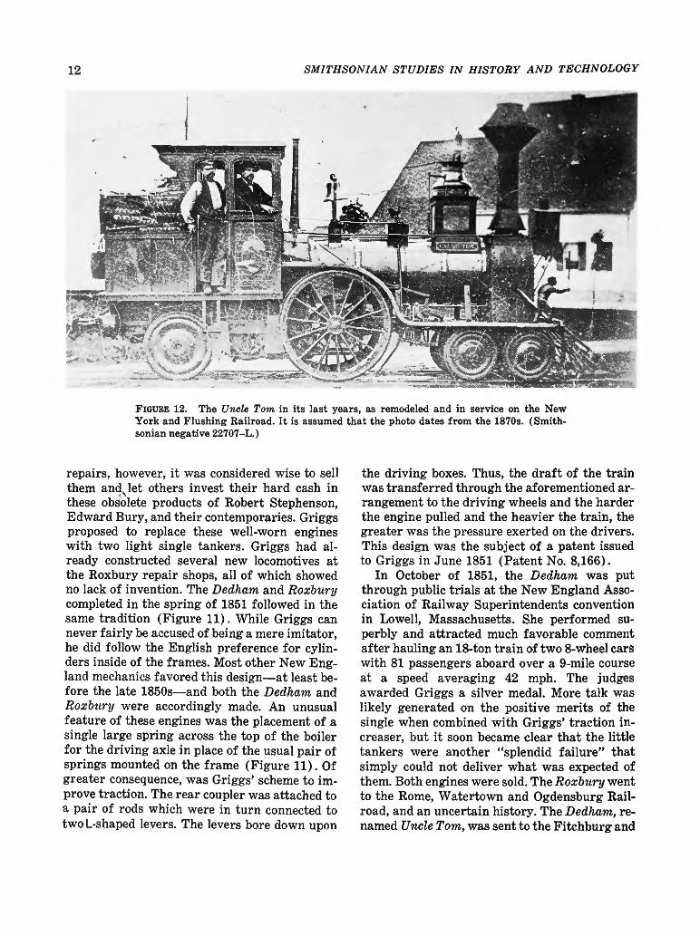
FIGURE 23. The Pioneer, built in 1851, shown here as renovated and exhibited in the Museum of History and Technology, 1964. In 1960 the locomotive was given to the Smithsonian Institution by the Pennsylvania Railroad through John S. Fair, Jr. (Smithsonian negative 63344B.)

22 SMITHSONIAN STUDIES IN HISTORY AND TECHNOLOGY
11 rrn i • ' » ' » * *
FIGURE 24. Diagram comparing the Pioneer (shaded drawing) with the Columbia, standard 8-wheel engine of 1851. (Drawing by J. H. White.)
Columbia Hudson River Railroad Lowell Machine Shop, 1852 Wt. 27% tons (engine only) Cyl. 16% x 22 inches Wheel diam. 84 inches
Pioneer Cumberland Valley Railroad Seth Wilmarth, 1851 12% tons 8% x 14 inches 54 inches
FIGURE 25. Pioneer, about 1901, showing the sandbox and large headlamp. Note the lamp on the cab roof, later used as the headlight. (Smithsonian negative 49272.)
NUMBER 25 23
heavy service. Figure 24, a diagram, is a comparison of the Pioneer and a standard eight-wheel locomotive.
Since the service life of the Pioneer was spent on the Cumberland Valley Railroad, a brief account of that line is necessary to an understanding of the service history of this locomotive.
The Cumberland Valley Railroad
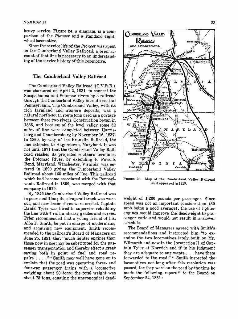
The Cumberland Valley Railroad (C.V.R.R.) was chartered on April 2, 1831, to connect the Susquehanna and Potomac rivers by a railroad through the Cumberland Valley in south-central Pennsylvania. The Cumberland Valley, with its rich farmland and iron-ore deposits, was a natural north-south route long used as a portage between these two rivers. Construction began in 1836, and because of the level valley some 52 miles of line were completed between Harris-burg and Chambersburg by November 16,1837. In 1860, by way of the Franklin Railroad, the line extended to Hagerstown, Maryland. It was not until 1871 that the Cumberland Valley Railroad reached its projected southern terminus, the Potomac River, by extending to Powells Bend, Maryland. Winchester, Virginia, was entered in 1890 giving the Cumberland Valley Railroad about 165 miles of line. This railroad which had become associated with the Pennsylvania Railroad in 1859, was merged with that company in 1919.
By 1849 the Cumberland Valley Railroad was in poor condition; the strap-rail track was worn out, and new locomotives were needed. Captain Daniel Tyler was hired to supervise rebuilding the line with T-rail, and easy grades and curves. Tyler recommended that a young friend of his, Alba F. Smith, be put in charge of modernizing and acquiring new equipment. Smith recommended to the railroad's Board of Managers on June 25, 1851, that "much lighter engines than those now in use may be substituted for the passenger transportation and thereby effect a great saving both in point of fuel and road repairs . . . ."16 Smith may well have gone on to explain that the road was operating three- and four-car passenger trains with a locomotive weighing about 20 tons; the total weight was about 75 tons, equaling the uneconomical dead-
FIGURE 26. Map of the Cumberland Valley Railroad as it appeared in 1919.
weight of 1,200 pounds per passenger. Since speed was not an important consideration (30 mph being a good average), the use of lighter engines would improve the deadweight-to-passenger ratio and would not result in a slower schedule.
The Board of Managers agreed with Smith's recommendations and instructed him "to examine the two locomotives lately built by Mr. Wilmarth and now in the [protection?] of Captain Tyler at Norwich and if in his judgment they are adequate to our wants . . . have them forwarded to the road." 1; Smith inspected the locomotives not long after this resolution was passed, for they were on the road by the time he made the following report1S to the Board on September 24, 1851:

24 SMITHSONIAN STUDIES IN HISTORY AND TECHNOLOGY
In accordance with a resolution passed at the last meeting of your body relative to the small engines built by Mr. Wilmarth I proceeded to Norwich to make trial of their capacity—fitness or suitability to the Passenger transportation of our Road—and after as thorough a trial as circumstances would admit (being on another Road than our own) I became satisfied that with some necessary improvements which would not be expensive (and are now being made at our shop) the engines would do the business of our Road not only in a manner satisfactory in point of speed and certainty but with greater ultimate economy in Expenses than has before been practised in this Country.
After making the above trial of the Engines—I stated to your Hon. President the result of the trial—with my opinion of their Capacity to carry our passenger trains at the speed required which was decidedly in favor of the ability of the Engines. He accordingly agreed that the Engines should at once be forwarded to the Road in compliance with the Resolution of your Board. I immediately ordered the Engines shipped at the most favorable rates. They came to our Road safely in the Condition in which they were shipped. One of the Engines has been placed on the Road and I believe performed in such a manner as to convince all who are able to judge of this ability to perform—although the maximum duty of the Engines was not performed on account of some original defects which are now being remedied as I before stated.
Within ten days the Engine will be able to run regularly with a train on the Road where in shall be enabled to judge correctly of their merits.
An accident occurred during the trial of the Small Engine at Norwich which caused a damage of about $300 in which condition the Engine came here and is now being repaired—the cost of which will be presented to your Board hereafter. As to the fault or blame of parties connected with the accident as also the question of responsibility for Repairs are questions for your disposal. I therefore leave the matter until further called upon.
The Expenses necessarily incurred by the trial of the Engines and also the Expenses of transporting the same are not included in the Statement herewith presented, the whole amount of which will not probably exceed $400.00.
These two locomotives became the Cumberland Valley Railroad's Pioneer (No. 13) and Jenny Lind (No. 14). While Smith notes that one of the engines was damaged during the inspection trials, Joseph Winters, an employee of the Cumberland Valley who claimed he was accompanying the engine en route to Chambers-burg at the time of their delivery, later recalled that both engines were damaged in transit.10
FIGURE 27. The Utility as rebuilt into an 8-wheel tank engine subsequent to an 1862 collision with a Northern Central locomotive while pulling a hospital train loaded with Civil War wounded. It was purchased by the Carlisle Mfg. Co. in 1882 and was last used in 1896. (Smithsonian negative 36,716-F.)

NUMBER 25 25
According to Winters a train ran into the rear of the Jenny Lind, damaging both it and the Pioneer, the accident occurring near Middle-town, Pennsylvania. The Jenny Lind was repaired at Harrisburg; the Pioneer, less seriously damaged, was taken for repairs to the main shops of the Cumberland Valley road at Chambersburg.
While there seems little question that these locomotives were not built as a direct order for the Cumberland Valley Railroad, an article appearing in the Railroad Advocate in 1855 credits their design to Smith. The article speaks of a 2-2-4 built for the Macon and Western Railroad and says in part:
This engine is designed and built very generally upon the ideas, embodied in some small tank engines designed by A. F. Smith, Esq., for the Cumberland Valley road. Mr. Smith is a strong advocate of light engines, and his novel style and proportions of engines, as built for him a few years since, by Seth Wilmarth, at Boston, are known to some of our readers. Without knowing all the circumstances under which these engines are worked on the Cumberland Valley road, we should not venture
to repeat all that we have heard of their performances, it is enough to say that they are said to do more, in proportion to their weight, than any other engines now in use."
The author believes that the Railroad Advocate's claim of Smith's design of the Pioneer has been confused with his design of the Utility (Figures 27 and 28). Smith designed this com-pensating-lever engine to haul trains over the C.V.R.R. bridge at Harrisburg. It was built by Wilmarth in 1854.
According to statements of Smith and the Board of Managers quoted on page 24, the Pioneer and the Jenny Lind were not new when purchased from their maker, Seth Wilmarth. Although of recent manufacture, previous to June 1851, they were apparently doing service on a road in Norwich, Connecticut. It should be mentioned that both Smith and Tyler were formerly associated with the Norwich and Worcester Railroad, and they probably learned of these two engines through this former asso-
FIGURE 28. The Utility, designed by A. F. Smith and constructed by Seth Wilmarth in 1854, was built to haul trains across the bridge at Harrisburg, Pennsylvania.

26 SMITHSONIAN STUDIES IN HISTORY AND TECHNOLOGY
ciation. It is possible that the engines were purchased from Wilmarth by the Cumberland Valley road, which had bought several other locomotives from Wilmarth in previous years. It was the practice of at least one other New England engine builder, the Taunton Locomotive Works, to manufacture engines on the speculation that a buyer would be found; if no immediate buyers appeared, the engine was leased to a local road until a sale was made.21
Regarding the Jenny Lind and Pioneer, Smith reported 22 to the Board of Managers at their meeting of March 17,1852:
The small tank engines which were purchased last year . . . and which I spoke in a former report as undergoing at that time some necessary improvements have since that time been fairly tested as to their capacity to run our passenger trains and proved to be equal to the duty.
The improvements proposed to be made have been completed only on one engine [Jenny Lind] which is now running regularly with passenger trains—the cost of
repairs and improvements on this engine (this being the one accidentally broken on the trial) amounted to $476.51. The other engine is now in the shop, not yet ready for service but will be at an early day.
The Pioneer and Jenny Lind achieved such success in action that the president of the road, Frederick Watts, commented on their performance in the annual report of the Cumberland Valley Railroad for 1851. Watts stated that since their passenger trains were rarely more than a baggage car and two coaches, the light locomotives ". . . have been found to be admirably adapted to our business." The Cumberland Valley Railroad, therefore, added two more locomotives of similar design in the next few years. These engines were the Boston and the Enterprise, also built by Wilmarth in 1854-1855.
Watts reported the Pioneer and Jenny Lind cost $7,642. A standard eight-wheel engine cost about $6,500 to $8,000 each during this period.
TABLE 2. Yearly mileage of the Pioneer
(From Annual Reports, Cumberland Valley Railroad)
Year Miles
1852 *3,182 1853 »>20, 722 1854 18,087 1855 14,151 1856 20,998 1857 22,779 1858 29,094 1859 29,571 1860 4,824 1861 4,346 1862 («) 1863 5,339 1864 224 1865 2,215 1866 20,546 1867 5,709
Year Miles
1868 13,626 1869 1,372 1870 1871 2,102 1872 4,002 1873 3,721 1874 3,466 1875 636 1876 870 1877 406 1878 4,433 1879 1880 8,306 1881 (d)
Total e 244, 727
" Mileage 1852 for January to September (no record of mileage recorded in Annual Reports C.V.R.R. previous to 1852).
D 15,000 to 20,000 miles per year was considered very high mileage for a locomotive of the 1850s.
- No mileage reported for any engines due to fire. d Not listed on roster. e The Pennsylvania Railroad claims a total mileage of
255,675. This may be accounted for by records of mileages for 1862, 1870, and 1879.
Exhibits of the Pioneer The Pioneer has been a historic relic since
1901. In the fall of that year, minor repairs were made to the locomotive so that it might be used in the sesquicentennial celebration at Carlisle, Pennsylvania. On October 22, 1901, the engine was ready for service, but as it neared Carlisle a copper flue burst. The fire was extinguished and the Pioneer was pushed into town by another engine. In the twentieth century, the Pioneer was displayed at the Louisiana Purchase Exposition, Saint Louis, Missouri, in 1904, and at the Wheeling, West Virginia, semicentennial in 1913. In 1927 it joined many other historic locomotives at the Baltimore and Ohio Railroad's "Fair of the Iron Horse" which commemorated the first one hundred years of that company. From about 1913 to 1925 the Pioneer also appeared a number of times at the Appleblossom Festival at Winchester, Virginia. In 1933-1934 it was displayed at the world's fair in Chicago, and in 1948-1949 at the Railroad Fair in the same city. Between 1934 and March 1947, it was exhibited at the Franklin Institute, Philadelphia, Pennsylvania.

NUMBER 25
In recent years, the Pennsylvania Railroad has stated the Pioneer cost $6,200 in gold, but is unable to give the source for this information. The author discounts this statement, for it does not seem reasonable that a light, cheap engine of the pattern of the Pioneer could cost as much as a machine nearly twice its size.
Service History
After being put in service, the Pioneer continued to perform well and was credited as able to move a four-car passenger train along smartly at 40 mph.23 This tranquility was shattered in October 1862 by a raiding party led by Confederate General J. E. B. Stuart which burned the Chambersburg shops of the Cumberland Valley Railroad. The Pioneer, Jenny Lind, and Utility were partially destroyed. The Cumberland Valley Railroad in its report for 1862 stated:
The Wood-shop, Machine-shop, Black-smith-shop, Engine-house, Wood-sheds, and Passenger Depot were totally consumed, and with the Engine-house three second-class Engines were much injured by the fire, but not so destroyed but that they may be restored to usefulness.
No record can be found, however, of the extent or exact nature of the damage. The shops and a number of cars were burned, so it is reasonable to assume that the cab and other wooden parts of the locomotive were damaged. One unverified report in the files of the Pennsylvania Railroad states that part of the roof and brick wall fell on the Pioneer during the fire causing considerable damage. In June 1864 the Chambersburg shops were again burned by the Confederates, but on this occasion the railroad managed to remove all of its locomotives before the raid. During the Civil War, the Cumberland VaL. ley Railroad was obliged to operate longer passenger trains to satisfy the enlarged traffic. The Pioneer and its sister single-axle engines were found too light for these trains and were used only on work and special trains. Reference to Table 1 will show that the mileage of the Pioneer fell off sharply for the years 1860-1865.
In 1871 the Pioneer was remodeled by A. S. Hull, master mechanic of the railroad. The exact nature of the alterations cannot be determined, as no drawings or photographs of the engine previous to this time are known to exist. In fact,
27
the drawing (Figure 29) prepared by Hull in 1876 to show the engine as remodeled in 1871 is the oldest known illustration of the Pioneer. Paul Westhaeffer, a lifelong student of Cumberland Valley Railroad history, states that according to an interview with one of Hull's descendants the only alteration made to the Pioneer during the 1871 "remodeling" was the addition of a handbrake. The road's annual report of 1853 describes the Pioneer as a six-wheel tank engine. The report of 1854 mentions that the Pioneer used link motion. These statements are enough to give substance to the idea that the basic arrangement has survived unaltered and that it has not been extensively rebuilt, as was the Jenny Lind in 1878.
By the 1870s the Pioneer was too light for the heavier cars then in use, and by 1880 it had reached the end of its usefulness for regular service. After nearly thirty years on the road, it had run 255,675 miles. Two new passenger locomotives were purchased in 1880 to handle the heavier trains. In 1881 the Pioneer was dropped from the roster, but was used until about 1890 for work trains. After this time it was stored in a shed at Falling Spring, Pennsylvania, near the Chambersburg yards of the C.V.R.R.
Mechanical Description
The following paragraphs describe the mechanical details of the Pioneer as it appears on exhibition in the Smithsonian Institution's National Museum of History and Technology.
Boiler
The boiler is the most important and costly part of a steam locomotive, representing one-fourth to one-third of the total cost. A poorly built or designed boiler will produce a poor locomotive no matter how well made the remainder of the mechanism. The boiler of the Pioneer is of the wagon-top, crownbar, fire-tube style and is made of a 5/
16-inch thick, wrought-iron plate. The barrel is very small, in keeping with the size of the engine, being only 27 inches in diameter. While some readers may believe this to be an extremely early example of a wagon-top boiler, it should be remembered that most New England builders produced few locomotives with the

:*3a5K0C5:>. ir^x^rsfeascss
;•' . :- -X *

i
- *.
. . , • - • • » •
b «? \ , u i M $> « v ' ,» > i d ti
H ,* -
I ft I V
•5 r V MO|j -'*i»;a$Yt&
FIGURE 29. The earliest known illustration of the Pioneer, drawn by A. S. Hull, master mechanic of the Cumberland Valley Railroad in 1876. It depicts the engine as it appeared in 1871. (Photograph courtesy of Paul Westhaeffer.)

30 SMITHSONIAN STUDIES IN HISTORY AND TECHNOLOGY
OBMBUABB f i l l l T BAHMAB--SI FOR THE GOVERNMENT AND INFORMATION OF EMPLOYEES ONLY
Takes effect on Monday, November 18th, 1878, at 4 .30 A.
North'n Central Trains. Up Trains— Westwai
JJa-Con.luclori, Enginee Dispatchers, using ihe Ir H.i.iJ.'iri «nd Brldgepo «ide themselves .nth Join oftlic I umljerland Valley una Nortl Cenlml RmU-ny., nnd will bfl gover whilnonlhis Irsck hy the Hulei Regulations printed (hereon.
Tnti
Dillsburg Branch. SOITHU'JMII-
Les.e ! A Mechamciburg 1 8 1
9 Ddlsburg Junction . 0.
.6 . | Trindle Spring | 96 I ...
. v . . Ill Dilltburg
No. 17 Dillsburg
Accom.
P. M.
12 45
1 20 | 1 35 ! 140
| 2 . 0 » 2 13
No 15.
Wtlliams MM
It i. P.'June
DiL'sburg .
135 .
112
2 25
230
235
Southern Penn'a Rsil Rosd.
~33 JV"o Mill Tr'n 1'. M
3 23
4(111 I.e. 4. f>
4 35 4 47
453
5 05
5 2".
5 iT
• 41
5 49
coo 6 15
P M
Mont Alto Ha.I Rosd.
K f S T U J I i l
9.00
910
59.1
62 C
65 0
66 3
68 9
7iM
72 7
70 4
71 1
72 8
75 0
78 2
South Perm Jc.
. .Stone liralge.
... Williamson
.... /lochia!' . .
... Lehmn\let'i
Mcrrrrsburg Jane
2 i AlercmhuTii .
Met ctn&ui a Jane
.. n,Ckrt/'S .
. flutter's .
.Lauilon ..
. Richmond
No. 11
Freight.
P. M.
1201
12 20 12 35 12.40 1245
1.02
1 17
[ i a
1.45 II*. I *
2.34 2 39
H9.SH, 3 04 3 30 3 40 4 03
4 03
4 25 4 40
lia.oo 5 22
5 37
5 44
6 0 0 r M
Amve
1 No. 9
1 F.st
Fr.ighl.
A. M.
0 30
6 50
7 0 5 7 20
7 25
7 43
8 0 0
8 20
1».S5 9 . 1 0
9 29
9 34
9 42 10 05
1110.24 10 49
10 54
11.10
li.aa 1145 12 05
1217
12 23 12 40
140
2 10
2 15
2 40 o 10
3 40 113.4!.
4 15 P M
.1 l.y lull l*€.d llr
A . TL.. ( i A R n N E U , l..
FIGURE 30. Timetable of the Cumberland Valley Railroad for 1878.
Bury (dome) boiler and tha t the chief advocates of this later style were the Philadelphia builders. By the early 1850s the Bury boiler passed out of favor entirely, and the wagon top became the standard type of boiler with all builders in this country.
Sixty-three iron tubes, 1% by 85 inches long are used. The original tubes may have been
copper or brass, since these were easier to keep t ight than the less malleable iron tubes. The present tube sheet is of iron, but was originally copper. I ts thickness cannot be conveniently measured, but it is greater than tha t of the boiler shell, probably about i/2 to % inch. While copper tubes and tube sheets were not much used in this country after about 1870, copper was em-
NUMBER 25 31
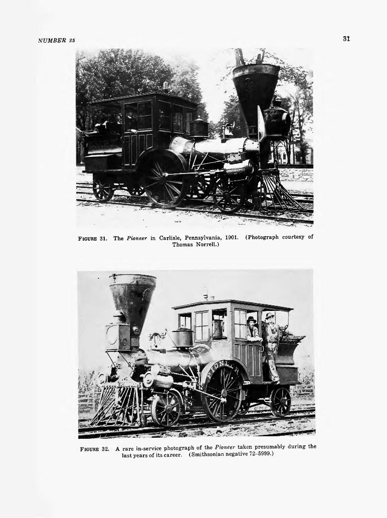
FIGURE 31. The Pioneer in Carlisle, Pennsylvania, 1901. (Photograph courtesy of Thomas Norrell.)
FIGURE 32. A rare in-service photograph of the Pioneer taken presumably during the last years of its career. (Smithsonian negative 72-5999.)

32 SMITHSONIAN STUDIES IN HISTORY AND TECHNOLOGY
ployed as recently as 1950 by Robert Stephenson & Hawthorns, Ltd., on some small industrial locomotives.
The boiler shell is lagged with wooden tongue-and-groove strips about 21/2 inches wide (felt also was used for insulation during this period). The wooden lagging is covered with Russia sheet iron which is held in place, and the joints are covered by polished brass bands. Russia sheet iron is a planish iron having a lustrous, metallic-gray finish.
The steam dome (Figure 39) is located directly over the firebox, inside the cab. It is lagged and jacketed in an identical manner to the boiler. The shell of the dome is of Y16-inch-thick wrought iron, the top cap is a cast-iron plate which also serves as a manhole cover offering access to the boiler's interior for inspection and repair.
A round plate, 20 inches in diameter, riveted on the forward end of the boiler, just behind the bell stand, was found when the old jacket was removed in May 1963. The size and shape of the hole, which the plate covers, indicate that a steam dome or manhole was located at this point. It is possible that this was the original location of
the steam dome, since many builders in the early 1850s preferred to mount the dome forward of the firebox. This was done in the belief that there was less danger of priming, because the water was less agitated forward of the firebox.
The firebox is as narrow as the boiler shell and fits easily between the frame. It is a deep and narrow box, measuring 27 inches by 28 inches by about 40 inches deep, and is well suited to burning wood. A deep firebox was necessary because a wide, shallow box suitable for coal burning allowed the fuel to burn so quickly that it was difficult to fire the engine effectively. With the deep, narrow firebox, wood was filled up to the level of the fire door. In this way, the fire did not burn so furiously and did not keep ahead of the fireman; at the same time, since it burned so freely, a good fire was always on hand. The Pioneer burned oak and hickory.29 For the firebox %6-inch-thick sheet was used, for heavier sheet would have blistered and flaked off because of the intense heat of the fire and the fibrous quality of wrought-iron sheet of the period. Sheet iron was fabricated from many small strips of iron rolled together while hot. These strips were ideally welded into a homogeneous
FIGURE 33. The Pioneer in Carlisle, Pennsylvania, 1901. Thomas Norrell.)
(Photograph courtesy of
NUMBER 25 33
£S 193
SOUTH BOSTON,
®IWB W 1 1 S A & T B . proprietor,
STATIONARY STEAM ENGINES AND STEAM BOILERS, OF THE VARIOUS SIZES REQUIRED,
Paris connected with Railroads, including Frogs, Switches, Chairs and Hand Cars.
MACHINISTS' TOOLS, of all descriptions, including TURNING LATHES, of sizes varying from 6 feet to 50 feet in length, and weighing from 500 pounds to 40 tons each ; the latter
capable of turning a wheel or pulley, thirty feet in diameter.
P L A N I N G M A C H I N E S ,
Varying from 2 feet to 60 feet in length, and weighing from 200 lbs. to 70 tons each, and will plane up to 55 feet long and 7 feet square.
Boring Mills, Vertical and Horizontal Drills, Slotting Machines, Punching Presses, Gear and Screw Cutting Machines, &c. &c. Also,
ittill bearing anb Shafting.
JOBBING AND REPAIRS, and any kind of work usually done in Ma-(. < \ chine Shops, executed at short notice.
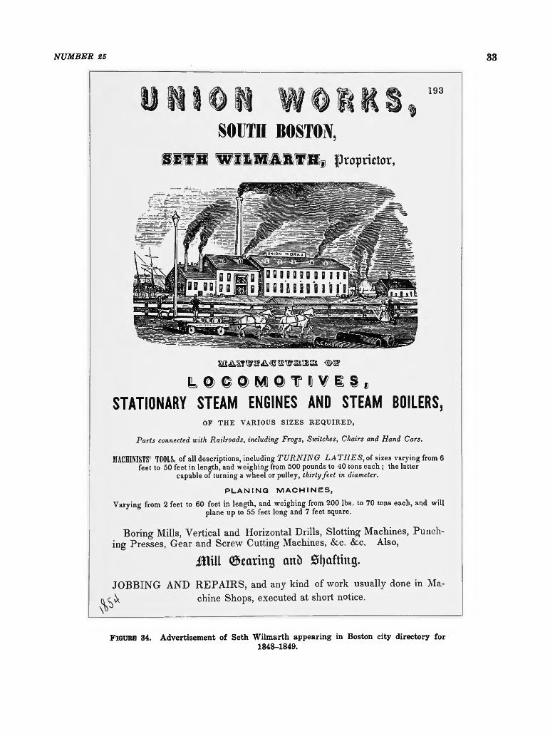
FIGURE 34. Advertisement of Seth Wilmarth appearing in Boston city directory for 1848-1849.

34 SMITHSONIAN STUDIES IN HISTORY AND TECHNOLOGY
FIGURE 35. The Pioneer as first exhibited in February 1961 in the Arts and Industries building of the Smithsonian Institution prior to restoration of the sandbox. (Smithsonian negative 48069D.)
sheet, but in practice it was found that the thicker the sheet the less sure the weld.
The fire grates are cast iron and set just a few inches above the bottom of the water space so that the water below the grates remains less turbulent, and mud or other impurities in the water settle here. Four bronze mud plugs and a blow-off cock are fitted to the base of the firebox so that the sediment thus collected can be removed (Figures 38 and 39).
The front of the boiler is attached to the frame by the smokebox, which is a cylinder, bolted on a light, cast-iron saddle (not part of the cylinder castings nor attached to them, but bolted directly to the top rail of the frame; it
may be a hastily made repair put on at the shops of the Cumberland Valley Railroad). The rear of the boiler is attached to the frame by two large cast-iron brackets, one on each side of the firebox (Figure 39). These are bolted to the top rail of the frame but the holes in the brackets are undoubtedly slotted, so tha t they may slide since the boiler will expand about 14 i n c n when heated. In addition to the crown bars, which strengthen the crown sheet, the boiler is further strengthened by stay bolts and braces located in the wagon top over the firebox where the boiler had been weakened by the large hole necessary for the steam dome. This boiler is a re-markedly light, strong, and compact structure.
NUMBER 25 35
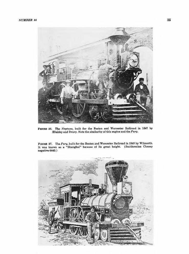
FIGURE 36. The Neptune, built for the Boston and Worcester Railroad in 1847 by Hinkley and Drury. Note the similarity of this engine and the Fury.
FIGURE 37. The Fury, built for the Boston and Worcester Railroad in 1849 by Wilmarth. It was known as a "Shanghai" because of its great height. (Smithsonian Chaney negative 6443.)
-

36 SMITHSONIAN STUDIES IN HISTORY AND TECHNOLOGY
>, bo C
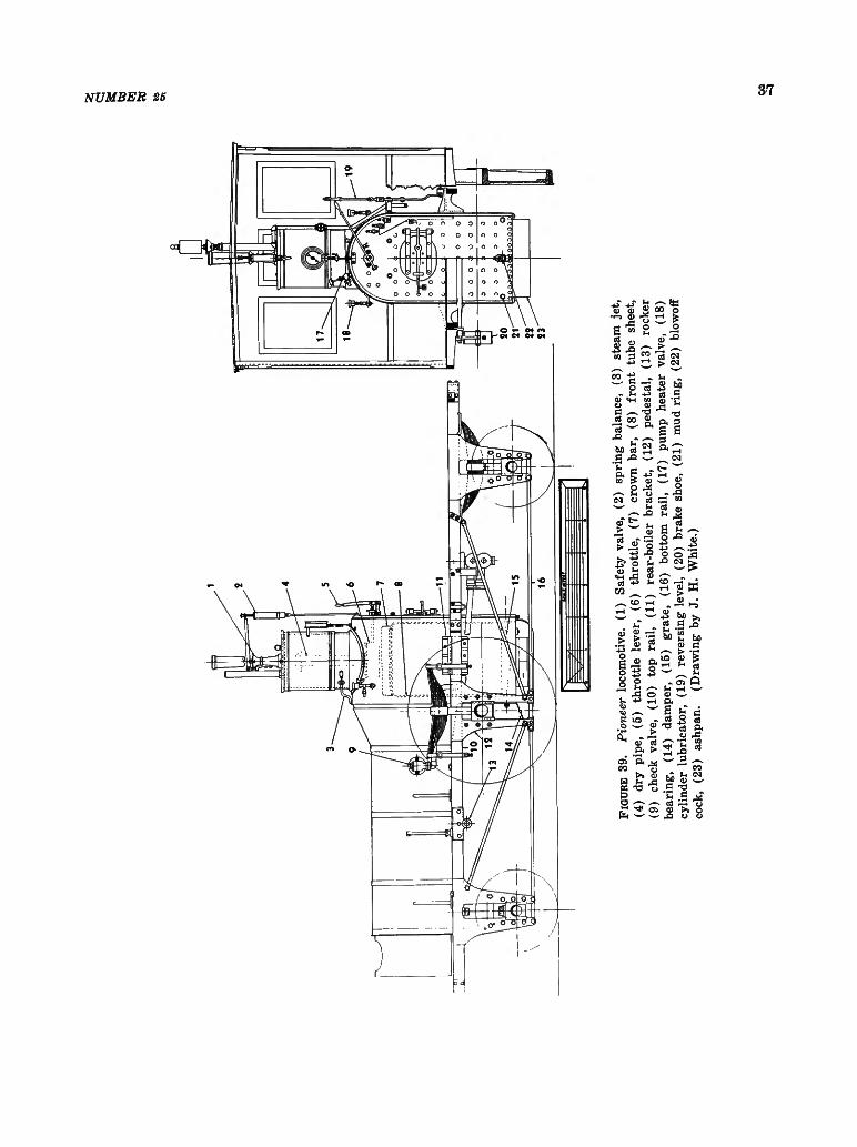
NUMBER 25 37
«u CO B O
team
j
be
she
1)
rod
Ive,
(1
)
blow
m
CO w'
nee
bala
ho C u t-u m
f M
*—'
ve,
val
£ «<H
ive.
(1
)
+ J
omo
o
S*
a
Pio
CO
a « 6 r i .
1 J J
G o !H
•H
0 0
03 - Q
_ O
& u
t -
oT
o h
4 2 -t->
CD
> <3J
.2 +3 o
r C - U
I P
, crt
4->
•o
P.
CM
4 J OJ
^ o c3 r - i
'S
0) >H
1-1 1-1
rH
a o
o i - H
a > a ^
T:
^ • * -
r
CT
irrt
> u <i>
rfl
P,
e - i a
r~ t H
7 ^
A
O
o -P
r H
+->
s-> ho
U3 T-H
r H CO P
S rt
T3
TH
M M
he 0
3
s r H CM
0 r i - ,
r ^
X
o CM
>
he
0)
> 0! rH
C7>
r H
K crj
- r-1
bC fc c T 3
U S <x> >
' X ! W
a>
4 =
ffi r-S
r »
hO
a
(-1
G crt p .
rP tn
CO CM
r *
o u

38 SMITHSONIAN STUDIES IN HISTORY AND TECHNOLOGY
Boiler Fittings
Few boiler fittings are found on the Pioneer, and it appears that little was done to update the engine with more modern devices during its many years of service. With the exception of the steam gauge, it has no more boiler fittings than when it left the builder's shop in 1851.
The throttle valve is a simple slide valve and must have been primitive for the time, for the
FIGURE 40. Backhead of the Pioneer. photo 48069F.)
(Smithsonian
balance-poppet throttle valve was in use in this country previous to 1851. It is located directly below the steam dome, even though it was common practice to place the throttle valve at the front of the boiler in the smokebox. Considering the cramped condition inside the smokebox, there would seem to be little space for the addition of the throttle valve; hence its present location. The dry pipe projects up into the steam dome to gather the hottest, driest steam for the cylinders. The inverted, funnel-like cap on the top of the dry pipe is to prevent priming, as drops of water may travel up the sides of the pipe and then to the cylinders, with the possibility of great damage. After the steam enters the throttle valve it passes through the front end of the valve, through the top of the boiler via the dry pipe (Figure 39), through the front tube sheet, and then to the cylinders via the petticoat pipes. The throttle lever is a simple arrangement readily understood from the drawings. It has no latch and the throttle lever is held in any desired setting by the wingnut and quadrant shown in Figure 39. The water level in the boiler is indicated by the three brass cocks located on the backhead. No gauge glass is used; they were not employed in this country until the 1870s, although they were commonly used in England at the time the Pioneer was built.
While two safety valves were commonly required, only one was used on the Pioneer. The safety valve is located on top of the steam dome. Pressure is exerted on the lever by a spring balance, fixed at the forward end by a knife-blade bearing. The pressure can be adjusted by the thumbscrew on the balance. The graduated scale on the balance gave a general but uncertain indication of the boiler pressure. The valve itself is a poppet held against the face of the valve seat by a second knife blade attached to the lever. The ornamental column forming the stand of the safety valve is cast iron and does much to decorate the interior of the cab. The pipe carrying the escaping steam projects through the cab roof. It is made of copper with a decorative brass band. This entire mechanism was replaced by a modern safety valve for use at the Chicago Railroad Fair (1948-1949). Fortunately, the old valve was preserved and has since been replaced on the engine.

NUMBER 25 39
FIGURE 41. Feedwater pump of the Pioneer. sonian negative 63344.)
(Smith-
The steam gauge is a later addition, but could have been put on as early as the 1860s, since the most recent patent date that it bears is 1859. It is an Ashcraft gauge having a handsome 4-4-0 locomotive engraved on its silver face.
The steam jet (item 3, Figure 39) is one of the simplest yet most notable boiler fittings of the Pioneer, being nothing more than a valve tapped into the base of the steam dome with a line running under the boiler jacket to the smokestack. When the valve is opened a jet of steam goes up the stack, creating a draft useful for starting the fire or enlivening it as necessary. This device was the invention of Alba F. Smith in 1852, according to the eminent nineteenth-century technical writer and engineer Zerah Colburn.30
The two feedwater pumps (Figure 41) are located beneath the cab deck (1, Figure 39).
FIGURE 42. Pioneer on exhibit in the Arts and Industries building of the Smithsonian Institution. In this view can be seen the bonnet screen of the stack and arrangement of the boiler-frame braces and other details not visible from the floor. (Smithsonian negative 48069A.)

40 SMITHSONIAN STUDIES IN HISTORY AND TECHNOLOGY
They are of cast-iron construction and are driven by an eccentric on the driving-wheel axle (Figure 48). The airchamber or dome (1, Figure 48) imparts a steadier flow of the water to the boiler by equalizing the surges of water from the reciprocating pump plunger. A steam line (3, Figure 39), which heats the pump and prevents freezing in cold weather, is regulated by a valve in the cab (Figures 39 and 48). Note that the line on the right side of the cab has been disconnected and plugged.
The eccentric drive for the pumps is unusual, and the author knows of no other American locomotive so equipped. Eastwick and Harrison, it is true, favored an eccentric drive for feed pumps, but they mounted the eccentric on the crankpin of the rear driving wheel and thus produced in effect a half-stroke pump. This was not an unusual arrangement, though a small crank was usually employed in place of the eccentric. The full-stroke crosshead pump with
which the Jenny Lind (Figure 43) is equipped, was of course the most common style of feed pump used in this country in the nineteenth century.
Of all the mechanisms on a nineteenth-century locomotive, the feed pump was the most troublesome. If an engineer could think of nothing else to complain about, he could usually call attention to a defective pump and not be found a liar. Because of this, injectors were adopted after their introduction in 1860. It is surprising that the Pioneer, which was in regular service as late as 1880 and has been under steam many times since for numerous exhibitions, was never fitted with one of these devices. Because its stroke is short and the plunger is in less rapid motion, the present eccentric arrangement would seem to have been more prone to disorder than the simpler but faster crosshead pump.
The check valves are placed slightly below the centerline of the boiler (Figure 39). These
FIGURE 43. Jenny Lind, sister engine of the Pioneer, shown here as rebuilt in 1878 for use as an inspection engine. It was scrapped in March 1905. (Photograph courtesy of E.P.Alexander.)
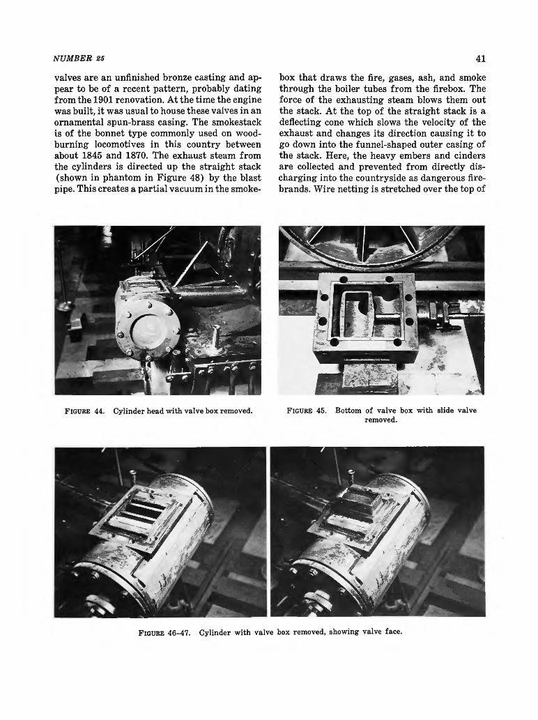
NUMBER 25 41
valves are an unfinished bronze casting and appear to be of a recent pattern, probably dating from the 1901 renovation. At the time the engine was built, it was usual to house these valves in an ornamental spun-brass casing. The smokestack is of the bonnet type commonly used on wood-burning locomotives in this country between about 1845 and 1870. The exhaust steam from the cylinders is directed up the straight stack (shown in phantom in Figure 48) by the blast pipe. This creates a partial vacuum in the smoke
box that draws the fire, gases, ash, and smoke through the boiler tubes from the firebox. The force of the exhausting steam blows them out the stack. At the top of the straight stack is a deflecting cone which slows the velocity of the exhaust and changes its direction causing it to go down into the funnel-shaped outer casing of the stack. Here, the heavy embers and cinders are collected and prevented from directly discharging into the countryside as dangerous firebrands. Wire netting is stretched over the top of
FIGURE 44. Cylinder head with valve box removed. FIGURE 45. Bottom of valve box with slide valve removed.
FIGURE 46-47. Cylinder with valve box removed, showing valve face.
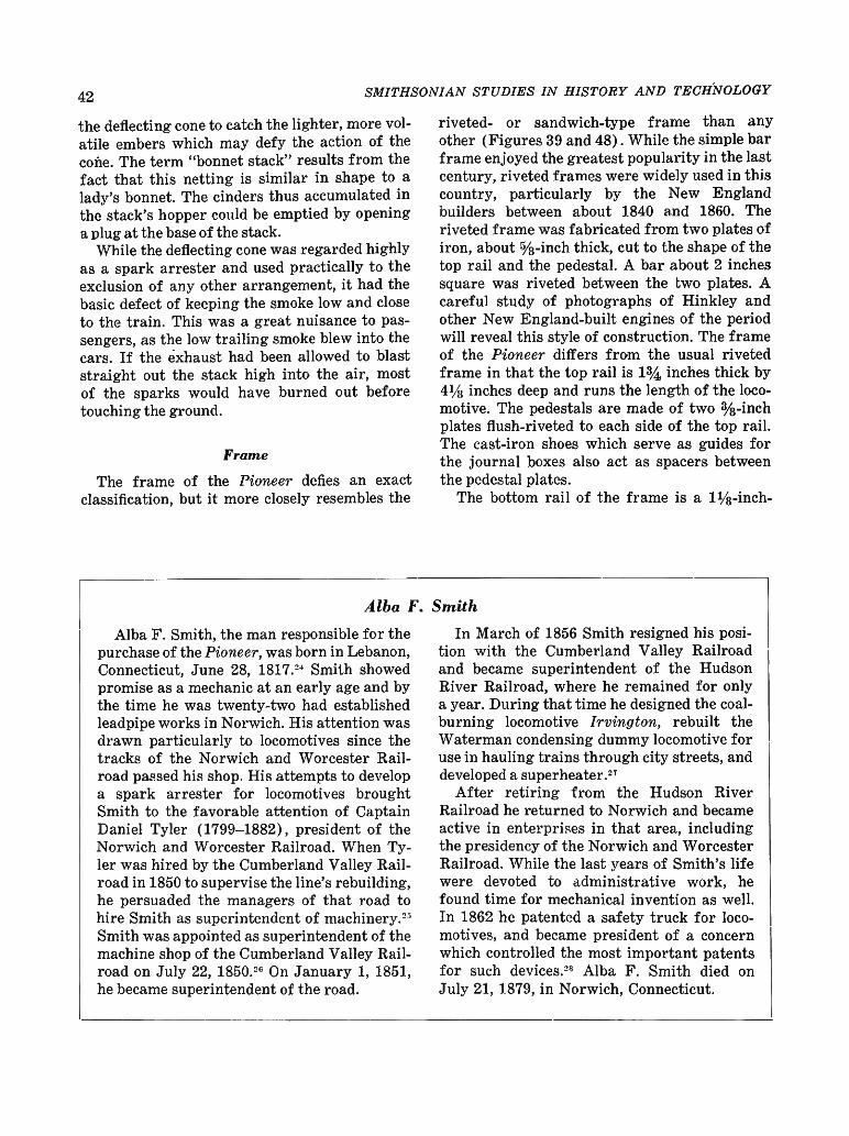
42 SMITHSONIAN STUDIES IN HISTORY AND TECHNOLOGY
the deflecting cone to catch the lighter, more volatile embers which may defy the action of the cone. The term "bonnet stack" results from the fact that this netting is similar in shape to a lady's bonnet. The cinders thus accumulated in the stack's hopper could be emptied by opening a plug at the base of the stack.
While the deflecting cone was regarded highly as a spark arrester and used practically to the exclusion of any other arrangement, it had the basic defect of keeping the smoke low and close to the train. This was a great nuisance to passengers, as the low trailing smoke blew into the cars. If the exhaust had been allowed to blast straight out the stack high into the air, most of the sparks would have burned out before touching the ground.
Frame
The frame of the Pioneer defies an exact classification, but it more closely resembles the
riveted- or sandwich-type frame than any other (Figures 39 and 48). While the simple bar frame enjoyed the greatest popularity in the last century, riveted frames were widely used in this country, particularly by the New England builders between about 1840 and 1860. The riveted frame was fabricated from two plates of iron, about %-inch thick, cut to the shape of the top rail and the pedestal. A bar about 2 inches square was riveted between the two plates. A careful study of photographs of Hinkley and other New England-built engines of the period will reveal this style of construction. The frame of the Pioneer differs from the usual riveted frame in that the top rail is 1% inches thick by 4% inches deep and runs the length of the locomotive. The pedestals are made of two %-inch plates flush-riveted to each side of the top rail. The cast-iron shoes which serve as guides for the journal boxes also act as spacers between the pedestal plates.
The bottom rail of the frame is a 1^-inch-
Alba F. Smith
Alba F. Smith, the man responsible for the purchase of the Pioneer, was born in Lebanon, Connecticut, June 28, 1817." Smith showed promise as a mechanic at an early age and by the time he was twenty-two had established leadpipe works in Norwich. His attention was drawn particularly to locomotives since the tracks of the Norwich and Worcester Railroad passed his shop. His attempts to develop a spark arrester for locomotives brought Smith to the favorable attention of Captain Daniel Tyler (1799-1882), president of the Norwich and Worcester Railroad. When Tyler was hired by the Cumberland Valley Railroad in 1850 to supervise the line's rebuilding, he persuaded the managers of that road to hire Smith as superintendent of machinery.2"5
Smith was appointed as superintendent of the machine shop of the Cumberland Valley Railroad on July 22, 1850Y On January 1, 1851, he became superintendent of the road.
In March of 1856 Smith resigned his position with the Cumberland Valley Railroad and became superintendent of the Hudson River Railroad, where he remained for only a year. During that time he designed the coal-burning locomotive Irvington, rebuilt the Waterman condensing dummy locomotive for use in hauling trains through city streets, and developed a superheater.27
After retiring from the Hudson River Railroad he returned to Norwich and became active in enterprises in that area, including the presidency of the Norwich and Worcester Railroad. While the last years of Smith's life were devoted to administrative work, he found time for mechanical invention as well. In 1862 he patented a safety truck for locomotives, and became president of a concern which controlled the most important patents for such devices.28 Alba F. Smith died on July 21, 1879, in Norwich, Connecticut.

NUMBER 25 43
diameter rod which is forged square at the pedestals and forms the pedestal cap. The frame is further stiffened by two diagonal rods running from the top of each truck-wheel pedestal to the base of the driving-wheel pedestal, forming a truss. Six rods, riveted to the boiler shell and bolted to the frame's top rail, strengthen the frame laterally. Four of these rods can be seen easily as they run from the frame to the middle of the boiler; the other two are riveted to the underside of the boiler. The attachment of these rods to the boiler was an undesirable
practice, for the boiler shell was thus subjected to the additional strain of the locomotive's vibrations as it passed over the road. In later years, as locomotives grew in size, this practice was avoided and frames were made sufficiently strong to hold the engine's machinery in line without using the boiler shell.
The front and rear frame beams are of flat iron plate bolted to the frame. The rear beam had been pushed in during an accident, and instead of its being replaced, another plate was riveted on and bent out in the opposite direction
Seth Wilmarth
Little is known of the builder of the Pioneer, Seth Wilmarth, and nothing in the way of a satisfactory history of his business is available. For the reader's general interest the following information is noted.31
Seth Wilmarth was born in Brattleboro, Vermont, on September 8,1810. He is thought to have learned the machinist trade in Paw-tucket, Rhode Island, before coming to Boston and working for the Boston Locomotive Works, Hinkley and Drury proprietors. In about 1836 he opened a machine shop and, encouraged by an expanding business, in 1841 he built a new shop in South Boston which became known as the Union Works.32
Wilmarth was in the general machine business, but his reputation was made in the manufacture of machine tools, notably lathes. He is believed to have built his first locomotive in 1842, but locomotive building never became his main line of work. Wilmarth patterned his engines after those of Hinkley and undoubtedly, in common with the other New England builders of this period, favored the steady-riding, inside-connection engines. The "Shanghais," so-called because of their great height, built for the Boston and Worcester Railroad by Wilmarth in 1849, were among the best known inside-connection engines operated in this country (Figure 37). While the greater part of Wilmarth's engines was built for New England roads, many were
constructed for lines outside that area, including the Pennsylvania Railroad, Ohio and Pennsylvania Railroad, and the Erie.
A comparison of the surviving illustrations of Hinkley and Wilmarth engines of the 1850s reveals a remarkable similarity in their details (Figures 36 and 37). Notice particularly the straight boiler, riveted frame, closely set truck wheels, feed-water pump driven by a pin on the crank of the driving wheel, and details of the dome cover. All of the features are duplicated exactly by both builders. This is not surprising considering the proximity of the plants and the fact that Wilmarth had been previously employed by Hinkley.
In 1854 Wilmarth was engaged by the New York and Erie Railroad to build fifty 6-foot gauge engines.33 After work had been started on these engines and a large store of material had been purchased for their construction, Wilmarth was informed that the railroad could not pay cash and that he would have to take notes in payment.34 There was at this time a mild economic panic, and notes could be sold only at a heavy discount. This crisis closed the Union Works. The next year, 1855, Seth Wilmarth was appointed master mechanic of the Charlestown Navy Yard, Boston, where he worked for twenty years. He died in Maiden, Massachusetts, on November 5,1886.

44 SMITHSONIAN STUDIES IN HISTORY AND TECHNOLOGY
0 3 o u
'—'
er,
lev
hil
sinj
r H
cu l> <1) r H
,—s <N
rH 0)
r P
!d ed
r P
u r H
«, ^-v. 1 - t W
tive
. lo
com
o m
eer
•?*
" H
0 0 T f
H os r-J
o l-H
rH ID
:,_) O r P
O -t->
CI. 0
U <X>
1 3 Ol
t -
u Q>
r - H CJ o r H
CO
fn"
ho c rrt
r P
r - N
c ~ I P
« M
Cx!
to
he 0 'm rH
> r H
^
+ J
r C
fin
c3 CQ a- +2
X UJ
CO i H CO — •
- U
« » &S Hg -— -u
0) - TJ
r H d> ,—s
hO LO 0 i-t P *— P i
_ -!-> Pn CD
2 o r - H r P
rH hD rH 0 ""' "-£>
., -r-> CJ CD
i f <JJ 0 U CO • [ -
r H
-' a * 1 p 3 3 a
rH ^ - s (J) O l -rJ w OJ
• r f l O ID
3 ^ , « co 0 rH
S '*"' ,—s CD 00 P
-- 3 r f i
£ « I—,
>> r P
to 0
H e$ r H
'—' rH Or P U H o
r P
M u ca co
1— r H

NUMBER 25 45
M X T xt
tj > P
-
-^:Hi-
'3 K
• a * P 3
5- - r -
s g •8 Q OH W
f=n
•^f
OH

46 SMITHSONIAN STUDIES IN HISTORY AND TECHNOLOGY
to form a pocket for the rear coupling pin. Note that there is no drawbar and that the coupler is merely bolted to the beams. Since the engine only pulled light trains, the arrangement was sufficiently strong.
Running Gear
The running gear is simply sprung with individual leaf springs for each axle; it is not connected by equalizing levers. To find an American locomotive not equipped with equalizers is sur-
FIGURE 50. The Pioneer was exhibited at the Franklin Institute between 1934 and 1948. (Pennsylvania Railroad negative E17414.)

NUMBER 25 47
prising since they were almost a necessity to produce a reasonably smooth ride on the rough tracks of American railroads. Equalizers steadied the motion of the engine by distributing the shock received by any one wheel or axle to all the other wheels and axles so connected, thus minimizing the effects of an uneven roadbed. The author believes that the Pioneer is a hard-riding engine.
The springs of the main drives are mounted in the usual fashion. The rear boiler bracket (Figure 39) is slotted so that the spring hanger may pass through for its connection with the frame. The spring of the leading wheels is set at right angles to the frame (Figure 48) and bears on a beam, fabricated of iron plate, which in turn bears on the journal boxes. The springs of the trailing wheels are set parallel with the frame and are mounted between the pedestal plates (Figure 39).
The center of the driving wheel is cast iron and has spokes of the old rib pattern, which is a T in cross-section, and was used previous to the adoption of the hollow-spoke wheel. In the mid-1830s Baldwin and others used this rib-pattern style of wheel, except that the rib faced inside. The present driving-wheel centers are unquestionably original. The sister engine, Jenny Lind (Figure 43), was equipped with identical driving wheels. The present tires are very thin and beyond their last turning. They are wrought iron and shrunk to fit the wheel centers. Flush rivets are used for further security. The left wheel, shown in Figure 38, is cracked at the hub and is fitted with an iron ring to prevent its breaking.
The truck wheels, of the hollow-spoke pattern, are cast iron with chilled treads. They were made by Asa Whitney, one of the leading car-wheel manufacturers in this country, whose extensive plant was located in Philadelphia. Made under Whitney's patent of 1866, these wheels may well have been added to the Pioneer during the 1871 rebuilding. Railroad wheels were not cast from ordinary cast iron, which was too weak and brittle to stand the severe service for which they were intended, but from a high-quality cast iron similar to that used for cannons. Its tensile strength which ranged from 31,000 to 36,000 psi, was remarkably high and very nearly ap
proached that of the best wrought-iron plate. The cylinders are cast iron with an 814-inch
bore about half the size of the cylinders of a standard eight-wheel engine. The cylinders are bolted to the frame but not to the saddle and are set at a 9 degree angle to clear the leading wheels and at the same time to line up with the center of the driving-wheel axle. The wood lagging is covered with a decorative brass jacket. Ornamental brass jacketing was extensively used on mid-nineteenth-century American locomotives to cover not only the cylinders, but steam chests and sandboxes, check valves, and valve boxes. The greater expense for brass (Russia iron or painted sheet iron were a cheaper substitute) was justified by the argument that brass lasted the life of the engine, and could be reclaimed for scrap at a price approaching the original cost; and also that when brightly polished it reflected the heat, preventing loss by radiation; and its bright surface could be seen a great distance, thus helping to prevent accidents at grade crossings. The reader should be careful not to misconstrue the above arguments simply as rationalization on the part of master mechanics more intent on highly decorative machines than on the practical considerations involved.
The valve box, a separate casting, is fastened to the cylinder casting by six bolts. The side cover plates when removed show only a small opening suitable for inspection and adjustment of the valve. The valve box must be removed to permit repair or removal of the valve. A better understanding of this mechanism and the layout of the parts can be gained from a study of Figures 44, 47, and 49 (8, 8A, and 8B) .
Both crossheads were originally of cast iron, but one of these has been replaced and is of steel. They run into steel guides, bolted at the forward end to the rear cylinder head and supported in the rear by a yoke. The yoke is one of the more finished and better made pieces on the entire engine (Figure 48). The main rod is of the old pattern, round in cross-section, and only 1*4 inches in diameter at the largest point.
Valve Gear
The valve gear is of the Stephenson shifting-link pattern (see Figure 48), a simple and de-

48 SMITHSONIAN STUDIES IN HISTORY AND TECHNOLOGY
G ( S = ^
FIGURE 51. Reconstructed sandbox replaced on the locomotive, August 1962. (Drawing by J. H.White.)
FIGURE 52. This reproduction of the headlight, based on an 1852 patent model, was made in the Smithsonian's workshops by John Stine in 1965. (Smithsonian negative 60,240-A.)
pendable motion used extensively in this country between about 1850 and 1900. The author believes that this is the original valve gear of the Pioneer, since the first mention (1854) in the Annual Report of the Cumberland Valley Railroad of the style of valve gear used by each engine states that the Pioneer was equipped with a shifting-link motion. Assuming this to be the original valve gear of the Pioneer, it must be regarded as an early application, because the Stephenson motion was just being introduced into American locomotive practice in the early 1850s. Four eccentrics drive the motion; two are for forward motion and two are for reverse. The link is split and is made of two curved pieces. The rocker is fabricated of several forged pieces, keyed and bolted together. On better made engines, the rocker would be a one-piece forging. The lower arm of each rocker is curiously shaped, made with a slot so that the link block may be adjusted. Generally, the only adjustment possible was effected by varying the length of the valve stem by the adjusting nuts provided. A simple weight and lever attached to the revers-

NUMBER 25 49
ing shaft serve as a counterbalance for the links and thus assist the engineer in shifting the valve motion. There are eight positions on the quadrant of the reversing lever.
Miscellaneous Notes
The cab is solid walnut with a natural finish. It is very possible that the second cab was added to the locomotive after the 1862 fire. A brass gong used by the conductor to signal the engineer is fastened to the underside of the cab roof. This style of gong was in use in the 1850s and may well be original equipment.
The water tank is in two sections, one part extending below the deck, between the frame. The tank holds 600 gallons of water. The tender holds one cord of wood.
The small pedestal-mounted sandbox was used on several Cumberland Valley engines including the Pioneer. This box was removed from the engine sometime between 1901 and 1904. It was on the engine at the time of the Carlisle sesquicentennial, but disappeared by the time of the Saint Louis exposition. Two small sandboxes, mounted on the driving-wheel splash guards, replaced the original box. The large headlamp (Figure 25) apparently disappeared at the same time and was replaced by a crudely made lamp formerly mounted on the cab roof as a backup light. Headlamps of commercial manufacture were carefully finished and made with parobolic reflectors, elaborate burners, and handsomely fitted cases. Such a lamp could throw a beam of light for 1,000 feet. The present lamp has a flat cone-shaped piece of tin for a reflector.
The brushes attached to the pilot were used in the winter to brush snow and loose ice off the rail and thus improve traction. In good weather, the brushes were raised UD to clear the tracks.
After the Pioneer came to the Smithsonian Institution, it was decided that some refinishing was required to return it as nearly as possible to the state of the original engine. Replacing the sandbox was an obvious change.35 The brass cylinder jackets were also replaced. The cab was stripped and carefully refinished as natural wood. The old safety valve was replaced, as already mentioned. Rejacketing the boiler with
simulated Russia iron produced a most pleasing effect, adding not only to the authenticity of the display but making the engine appear lighter and relieving the somber blackness which was not characteristic of a locomotive of the 1850s.
The question arises, has the engine survived as a true and accurate representation of the original machine built in 1851 ? In answer, it can be said that although the Pioneer was damaged en route to the Cumberland Valley Railroad, modified on receipt, burned in 1862, and operated for altogether nearly forty years, surprisingly few new appliances have been added, nor has the general arrangement been changed. Undoubtedly, the main reason the engine is so little changed is that its small size and odd framing did not invite any large investment for extensive alteration for other uses. But there can be no positive answer as to its present variance from the original appearance as represented in the oldest known illustration of it— the Hull drawing of 1871 (Figure 29). There are few, if any, surviving nineteenth-century locomotives that have not suffered numerous re-buildings and are not greatly altered from the original. The John Bull, also in the Smithsonian's collections, is a good example of a machine many times rebuilt in its thirty years of service.36 Unless other information is uncovered to the contrary, it can be stated that the Pioneer is a true representation of a light passenger locomotive of 1851.
Since the publication of the first edition of this study of the Pioneer in 1964, restoration of the locomotive has continued. The crude replica headlight was replaced by a more perfect replica made in the museum's workshops by John Stine (Figure 52). Its general size and details were based on a large-scale patent model for T. Snook and S. Hill's (Patent No. 9,490, December 21, 1852) locomotive head lantern now in the collections of the Baltimore and Ohio Transportation Museum. The blowoff cocks and connecting linkage to the cab have been replaced. In February 1966, the old-style, valve-chest mounted, oil cups were installed.
In the process of removing the paint from the feed-water pumps, it was discovered that the right-hand pump was a solid cast-iron dummy. Apparently, it was fabricated as a cosmetic re-

50 SMITHSONIAN STUDIES IN HISTORY AND TECHNOLOGY
placement for the original, which had been lost or was so badly corroded that a facsimile was required.
NOTES
1. Of the several hundred 4-2-0s built in the United States in the 1830s and 1840s, only a lone original example has survived to the present time. This machine is the Chicago and North Western's Pioneer now exhibited by the Chicago Historical Society.
2. American Locomotives: An Engineering History, 1830-1880 by John H. White, Jr . (Baltimore: Johns Hopkins Press, 1968).
3. Railway and Locomotive Historical Society Bulletin, no. 114 (April 1966), pp. 27-36.
4. Ibid. 5. Information on the Lovett Eames is from the fol
lowing sources: Railroad Gazette, May 7, 1880, p. 246; July 30, 1880, p. 409; August 18, 1882, p. 514; June 6, 1884, p. 423; and American Locomotive Engines by Emory Edwards (Philadelphia: Baird & Co., 1883), pp. 132-142.
6. Locomotive Engineering, 1895, pp. 500-503 and 587; and A Century of Reading Motive Power, no author (Philadelphia: Reading Company, 1941), p. 66.
7. Locomotive Engineering by Z. Colburn (London, 1871), p.77.
8. Railway and Locomotive Historical Society Bulletin, no. 47 (September 1938), pp. 79-85.
9. History of the Long Island Railroad, part 2, by V. E. Seyfried,p. 151.
10. A History of Industrial Paterson by L. R. Trumbull (Paterson, N.J., 1882), pp. 140-141.
11. Railway and Locomotive Historical Society Bulletin, no. 61 (May 1942), pp. 10-34. See also G. M. Best, "The Single Drivered Steam Locomotive in the West," The American Railroad Journal (San Marino, Calif.: Golden West Books, Pacific Railroad Publishers, Inc.), vol. 1.
12. Engineering News, vol. 23, no. 24 (June 18, 1890), p. 616; and Railway and Locomotive Historical Society Bulletin, no. 34 (May 1934), p 52.
13. American Engineer and Railroad Journal, vol. 68, no. 6 (June 1894), pp. 263-265.
14. Railway and Locomotive Historical Society Bulletin, no. 67 (May 1946), p. 70.
15. American Railway Review, vol. 5, no. 4 (August 15,1861), p. 42.
16. Minutes of the Board of Managers of the Cumberland Valley Railroad June 25,1851. This manuscript may be found in the office of the Secretary, Pennsylvania Railroad, Philadelphia, Pa. Hereinafter cited as Minutes C.V.R.R.
17.Ibid. 18. Minutes C.V.R.R. 19. Franklin Repository (Chambersburg, Pa . ) , Au
gust 26,1909. 20. Railroad Advocate (December 29,1855), vol. 2, p. 3. 21. C. E. FISHER, "Locomotives of the New Haven Rail
road," Railway and Locomotive Historical Society Bulletin, no. 46 (April 1938), p. 48.
22. Minutes C.V.R.R. 23. Evening Sentinel (Carlisle, Pa.) , October 23, 1901. 24. Norwich Bulletin (Norwich, Conn.), July 24, 1879.
All data regarding A. F. Smith is from this source unless otherwise noted.
25. Railway Age, vol. 14, no. 37 (September 13, 1889). Page 600 notes that Tyler worked on C.V.R.R. 1851-1852; Smith's obituary (footnote 24) mentions 1849 as the year; and minutes of C.V.R.R. mention Tyler as early as 1850.
26. Minutes C.V.R.R. 27 A. F. HOLLEY, American and European Railway
Practice (New York: 1861). An illustration of Smith's superheater is shown on plate 58, figure 13.
28. JOHN H. WHITE, Jr., "Introduction of the Locomotive Safety Truck," (Paper 24, 1961, in Contributions from the Museum of History and Technology: Papers 19-30, U.S. National Museum Bulletin, no. 228, Washington: Smithsonian Institution, 1963), p. 117.
29. Annual Report, Cumberland Valley Railroad, 1853. 30. ZERAH COLBURN, Recent Practice in Locomotive En
gines (1860),p.71. 31. Railroad Gazette (September 27, 1907), vol. 43, no.
13, pp. 357-360. These notes on Wilmarth locomotives by C. H. Caruthers were printed with several errors concerning the locomotives of the Cumberland Valley Railroad and prompted the preparation of these present remarks on the history of Wilmarth's activities. Note that on page 359 it is reported that only one compensating-lever engine was built for the C.V.R.R. in 1854, and not two such engines in 1852. The Pioneer is incorrectly identified as a "Shanghai," and as being one of three such engines built in 1871 by Wilmarth.
32. The author is indebted to Thomas Norrell for these and many of the other facts relating to Wilmarth's Union Works.
33. Railroad Gazette (October 1907), vol. 43, p. 382. 34. Boston Daily Evening Telegraph (Boston, Mass.),
August 11, 1854. The article stated that 1 engine a week was built and that 10 engines were already completed for the Erie. Construction had started on 30 others.
35. The restoration work has been ably handled by John Stine of the Smithsonian staff. Restoration started in October 1961.
36. American Locomotives (note 2) , pp. 248-268.
U.S. GOVERNMENT PRINTING OFFICE : 1973—O-494-500

