locomotive engineer training handbook · an important part of your locomotive engineer training...
TRANSCRIPT

LOCOMOTIVE ENGINEER TRAINING
HANDBOOK
February, 2006

Locomotive Control Stand Orientation
An important part of your Locomotive Engineer training will be operating locomotive simulators, and your first simulator activity will be very early in the class. The following pages are an introduction to some of the controls on a locomotive control stand. While there are some differences between locomotives, there are also many common items that are covered in the following pages. This material is intended more as an introduction; it will make your first simulator activities easier and will help you prepare for more material that will be covered in lessons on air brakes, preparing locomotives for service, dynamic braking and train handling. Your assignment for tonight is to read this material and answer the questions at the end. The assignment will be checked for completeness at the start of day one orientation. LET Staff


The reverser handle is the lowest handle on the control stand. It has three positions: left, centered, and right. When the handle is moved to the right, circuits are set up for the locomotive to move in that direction. When the handle is moved to the left, the locomotive will move in that direction when power is applied. With the reverser handle centered, mechanical interlocking prevents movement of the dynamic brake handle, but the throttle can be moved. In such case, power will not be applied to the traction motors.
Reverser Handle
The reverser handle is centered and removed from the panel to lock the throttle in IDLE position and the dynamic brake handle in OFF position.

Dynamic Brake Handle
The dynamic brake handle is located above the throttle handle. The brake handle has two positions; OFF and SETUP, and an operating range of 1 through 8 (FULL), through which the handle moves freely without notching. Mechanical interlocking prevents the dynamic brake handle from being moved out of the OFF position unless the throttle is in IDLE and the reverser is positioned either forward or reverse operation. CAUTION During transfer from power operation to dynamic braking, the throttle must be held in IDLE for at least 10 seconds before moving the dynamic brake handle to the SET UP position. This is to eliminate the possibility of a sudden surge of braking effort with possible train run-in or traction motor flash-over.

Throttle Handle The throttle handle is located just below the dynamic brake handle. It is
moved from right to left to increase locomotive power. The throttle has nine positions: IDLE, and 1 through 8 plus a STOP position, which is obtained by pulling the handle outward and moving it to the right beyond IDLE to stop all engines in a locomotive consist. Mechanical interlocking prevents the throttle handle from being moved out of IDLE into power positions when the dynamic brake handle is advanced to SET UP or beyond but it can be moved into STOP position to stop all engines in the consist. The throttle handle cannot be moved when the reverser handle is centered and removed from the controller. Locomotive Speed Indicator and Accelerometer

Accelerometer The accelerometer is a very useful tool for the locomotive engineer. It shows gain or loss of mph per minute. If the number is a positive number such as “3”, you are gaining 3mph per minute. If the number is a negative number such as “-3”, you are losing 3 mph per minute. With this information, you can make adjustments as needed if you are gaining or losing speed.
26 L Air Brake Equipment


Automatic Brake Valve

AUTOMATIC BRAKE VALVE HANDLE The automatic brake valve handle controls the application and release of both the locomotive and train brakes. The brake valve is of the “pressure maintaining type” which will hold brake pipe reductions constant against nominal brake pipe leakage. A brief description of the operating positions follows: Release Position This position is for charging the equipment and releasing the locomotive and train brakes. It is located with the handle at the extreme left of the quadrant. Minimum Reduction Position This position is located with the handle against the first raised portion on the quadrant to the right of the released position. With the handle moved to this position, a 6-8 pound brake pipe reduction is made and minimum braking effort is obtained. Service Zone This position consists of a sector of handle movement to the right of release position. In moving the handle from left to right through the service zone, the degree of braking effort is increased until, with the handle at the extreme right if this sector, the handle is in full service position and full service braking effort is obtained. Suppression Position This position is located with the handle against the second raised portion of the quadrant to the right of release position. In addition to providing full service braking effort, as with the handle in the full service position, it will also recover a penalty brake application.

Automatic Brake Valve

Handle Off Position This position is located by the first quadrant notch to the right of suppression position. This is the position in which the handle must be placed on trailing units of a multiple-unit locomotive or on locomotives being towed “dead” in a train. Emergency Position This position is located to the extreme right of the brake valve quadrant. It is the position that can be used to make a “desired” emergency brake application. This position must be used to reset either a “desired” or “undesired” brake application. CUT-OFF PILOT VALVE The cut-off pilot valve is located on the automatic brake valve housing directly beneath the automatic brake handle. The valve has two positions; IN or OUT. To operate the locomotive as the controlling unit, the cut-off valve must be pushed in and rotated to the IN position. The OUT position is used when making brake pipe leakage tests, a trailing unit in a consist, or hauling a locomotive “dead” in a consist. TRAINLINE AIR PRESSURE ADJUSTMENT VALVE The trainline air pressure adjustment valve is located to the left of the automatic brake valve. With the automatic brake handle in the released position, it is used to obtain the brake pipe pressure desired. The automatic brake valve will maintain the selected pressure against overcharge or leakage.

Independent Brake Valve
This handle provides independent control of the locomotive braking effort irrespective of train braking effort. The brake valve is self-lapping and will hold the brakes applied. A brief operating description of the operating positions follows: Release Position

This position is located with the handle at the extreme left of the quadrant. This position releases the locomotive brakes, provided the automatic brake handle is in the release position. Full Application Position This position is located with handle at the extreme right of the quadrant. In moving the handle from left to right through the service zone the degree of locomotive braking effort is increased until full application braking effort is obtained. Bail-off Position Depression of the independent brake handle whenever the handle is in the release position will cause the release of any automatic brake application existing on the locomotive. When an automatic brake application is made, the independent brake must be bailed off for 4 seconds per locomotive in the consist AND until the brake pipe air quits exhausting. MU-2A VALVE The MU-2A valve is located on the lower left hand side of the air brake stand. Its purpose is to set up the locomotive brake system for lead, trail, or dead operation. The positions are as follows: CLOSED IN TRAIL This position is used when the unit is trailing in a consist. OPEN IN LEAD OR DEAD This position is used when the unit is leading or dead.

Review Questions: 1. To remove the reverser handle, it must be in the ______________ position. 2. The Train Line Air Pressure Adjustment Valve (Equalizing Reservoir Regulating Valve) is located to the ______________ of the automatic brake handle. 3. When transitioning from power to dynamic brake, you must wait at least _______________before moving the dynamic brake handle to set up. 4. The dynamic brake handle can be moved with the reverser handle centered? T F 5. The throttle handle has a total of ____________ positions. 6. When a locomotive is a trailing unit, the automatic brake handle must be in the _____________ _____________ position. 7. When the independent brake is fully applied, the handle must be to the extreme _______________ position. 8. To bail off the independent brake when an automatic brake application is made, you must ____________ _____________ on the independent brake handle. 9. How long do you bail off the independent brake when an automatic brake application is made?

10. The automatic brake must be placed in the _________________ position to recover from a penalty brake application. 11. What tool is useful to the locomotive engineer when determining if he/she is gaining or losing speed?

NS LOCOMOTIVE ENGINEER TRAINING HANDBOOK

INTRODUCTION TO AIR BRAKES
AB-2
OBJECTIVE The purpose of this lesson is to familiarize the Locomotive Engineer Trainee with the air brakes on locomotives and freight cars. The air brake equipment on freight cars will be discussed. The trainee will be able to: x -Name the five major control valves on freight cars x -Explain how they differ in applying and releasing the brakes x -List the reservoirs on freight cars x -List the other components and their functions.
The trainee will be able to identify the air gauges associated with the air brake equipment and describe their function. The trainee will be able, by using the air gauges, to recognize a penalty brake application and an emergency brake application and be able to recover from each. The trainee will be able to name and describe the function of the components of the 26L brake equipment. The trainee will be able to name, locate and describe the positions of the 26L automatic brake valve. The trainee will be able to name, locate and describe the function of the positions of the 26L independent brake valve. The trainee will be able to locate, name, and describe the various manual cut-out cocks associated with the various locomotive brake equipment. In addition to the trainee demonstrating his ability to use the air brake equipment on the simulators he will be able to pass a written test, making a score of at least 80%.

AB-3
BASICS OF AIR BRAKES
A. THE STUDY OF AIR BRAKES
1. SCOPE No class of railroad employee should be more interested in furthering his
knowledge of air brakes than the locomotive engineer. Not only is his proficiency in train handling affected by his knowledge of air brakes - but his life may depend on this knowledge. Knowing the various types of equipment, how to set it up, how to manipulate it, how it functions, what to expect from it, what its limitations are, how to test it to determine if it is functioning properly, what to do if it should fail - all should be a part of the engineer's expertise.
We will not concern ourselves in this course with the internal port and passages
of the air brake components. Rather, we shall be concerned with what causes a device to operate and what results we should expect from its operation. If we are to test and operate the air brakes effectively, we must know beforehand what will occur during each event.
The subject of train handling is closely associated with the study of air brakes.
Since most train handling problems will arise during the slowing or stopping of the train, we shall learn certain guidelines that are accepted as the best operating practice for given conditions.
The modern freight train is longer, heavier and often faster than any of its
predecessors. These longer and heavier trains have placed new demands not only on the physical plant, but also on the men at their controls, the locomotive engineers. Successful train handling requires an ability to start and stop the train and to control the slack action while in motion through changing track gradients, curves and speed zones - all without accident or damage to equipment, track or lading. Failure or inability to properly control train speed or slack action may cost your life!

AB-4
B. GENERAL PRINCIPLES
1. SHOE ON WHEEL Ever since man invented the wheel, he has been occupied in developing a
better way to stop it. The most common method in use today is to force a stationary block against the rotating wheel. The more force exerted by the block, the greater will be the retarding affect. The block is commonly called a “brake shoe” and the purpose of a brake system is to force the shoe into contact with the wheel at varying pressures.
Brake shoes may be forced against the tread of the wheel, the rim or against a disc that is attached to the wheel or axle. In most railroad applications, the shoes are forced against the wheel tread as shown here. Brake shoes may be made of cast iron or composition material that will produce high friction. Whatever their substance, the shoe is intended to acquire the wear, not the wheel.
The friction caused by pressing the stationary shoe against a rotating wheel creates considerable heat. This heat is absorbed in the wheel as well as the shoe. During short periods of braking, the heat will be dissipated and cause no damage. However, prolonged braking can cause serious damage to the wheel.
AB-5
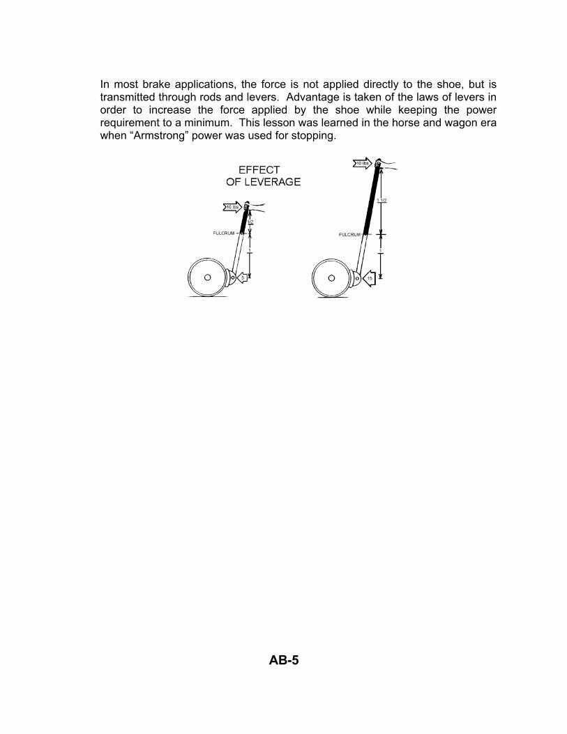
In most brake applications, the force is not applied directly to the shoe, but is transmitted through rods and levers. Advantage is taken of the laws of levers in order to increase the force applied by the shoe while keeping the power requirement to a minimum. This lesson was learned in the horse and wagon era when “Armstrong” power was used for stopping.

AB-6
2. AIR PRESSURE With the advent of air pressure to power the brake system, another means can
be added to increase or regulate the brake shoe pressure. By increasing the AREA on which the air pressure acts, the brake shoe pressure can be increased. Air pressure is always given in “Pounds per Square Inch” (P.S.I.). By increasing the area that the air pressure acts on, the total pressure can be increased.
Next, we see two brake cylinders. The one at the left has a piston area of only l0 square inches. When 10 pounds of air pressure is applied to each square inch, the total pressure will be 100 pounds. The same l0 psi is applied to the cylinder on the right, but its piston has an area of 30 square inches. With 10 pounds of pressure applied to each square inch, the total pressure at the shoe is 300 lbs. For this reason, we will find heavier cars have larger cylinders or more than one cylinder to increase the area. All of these things and many more are taken into consideration when designing a car or locomotive brake in order to supply a uniform braking effort throughout the train.

AB-7
Let's look at a typical brake cylinder to see how the air pressure is used to exert a force on the levers and consequently the brake shoes.
Here, we see the PISTON (at the left) which moves within the CYLINDER. When no air pressure is applied, the piston is held in this position by the RELEASE SPRING and the brake shoes are held away from the wheel. The PISTON ROD is moved out and in by the PISTON. A PACKING CUP is snapped over the piston to guard against leakage. Should any air pressure leak by the piston, a BREATHER in the NON-PRESSURE HEAD will allow it to vent to the atmosphere.

AB-8
When air pressure is directed to the CYLINDER, it quickly fills up the space between the PISTON and PRESSURE HEAD. Only 2 to 3 psi. is required to overcome the RELEASE SPRING and start the PISTON moving toward the right.
As the volume between the PRESSURE HEAD and PISTON increases, more air pressure must be supplied. But the cylinder pressure will not increase noticeably until the brake shoe contacts the wheel and all slack is taken up in the rods and levers. At this point, the PISTON ROD will be extended outward the same distance the PISTON has traveled. With the resistance of the brake shoes and rods preventing further movement, the air pressure will build up in the cylinder. Increasing the air pressure will increase the force on the brake shoe.
The BRAKE CYLINDER is an example of AIR PRESSURE acting against SPRING PRESSURE. No movement will take place until the air pressure on one side of the piston exceeds the spring pressure on the other side. In the case of a BRAKE CYLINDER, we use a very light spring (only about 2 to 3 pounds). But if we did not wish the device to move until a higher pressure was obtained, we could use a stronger spring!
A simple device that moves when air pressure is applied to either side is the DOUBLE CHECK VALVE. It consists of a close fitting CHECK that slides back and forth in a CYLINDER having 3 pipe connections.

AB-9
In the upper view, air pressure would be entering the left side (from the Independent Brake Valve). This pressure pushes the CHECK to the right, sealing the pipe connection closed on that side. It also allows the air pressure in the cylinder to flow downward (to apply the brakes.)
If air pressure enters from the right side (when using the Automatic Brake Valve), the check will be pushed to the left, cutting off the Independent Brake Valve. (Shown in the lower view). Air pressure from the automatic system will then flow downward (to apply the brakes). It can be seen here that whichever pressure is greater will control the brake application.
3. VOLUMES
Now that we have seen how air pressure is used to cause a device to move, let's investigate another item with which we must be thoroughly familiar in order to understand AIR BRAKES. That is, the flow of air pressure from a container of given volume into another container of different volume.
Here, we see a container (reservoir) on the left that is charged to 70 P.S.I. air pressure. A pipe connects the reservoir on the left to the container on the right, but a valve on that pipe is CLOSED. There is NO pressure in the container on the right, as can be seen by the gauge. The containers on the left hold 2 1/2 times the volume of the container on the right. Now, if we open the valve

AB-10
between the two tanks, air pressure will flow from the large tank that contained air pressure at 70 P.S.I. into the smaller tank that had no pressure. As the air pressure drops in the larger tank, it will build up in the smaller tank. Let's close the valve as soon as the gauge on the large tank drops to 60 P.S.I.
Q. Now, what will the gauge on the small tank read? A. Since the large tank has 2 1/2 times the volume of the small tank, each 1
pound that flows from the large tank will register 2 1/2 pounds when confined in the smaller tank. Thus, l0 pounds from the large tank will register 25 pounds on the gauge of the smaller tank!
Q. If we reopen the valve to allow the pressure in the large tank to drop
another l0 pounds (down to 50 P.S.I.), how much pressure would be shown on the gauge attached to the small tank?
A. Again, each pound from the large tank would register 2 1/2 pounds in the smaller tank so that 10 pounds would increase another 25 pounds to a total of 50 pounds. Now we have arrived at an important fact!
Q. What would happen if we allowed the valve to remain open? A. Nothing! Since the pressure remaining in the large tank is at 50 P.S.I. and
the pressure in the small tank has risen to 50 P.S.I., both tanks have equal pressure and no air will flow between them! This state (of equal pressures) is called “EQUALIZATION”. We shall see later how this fact will greatly affect our braking ability on a train.
C. HISTORY OF AIR BRAKES
1. STRAIGHT AIR SYSTEM The first power brakes were applied only to the locomotive and were operated
by steam pressure. A later development used steam pressure to drive an air pump and air pressure was used for the braking power.
It was not until 1869, that George Westinghouse designed a system that would
apply power brakes to the cars as well as the locomotive. This system employed a steam driven air compressor that pumped air into a large storage tank, or reservoir, on the locomotive.

AB-11
The engineer had a “Straight Air Valve” whereby he could direct air pressure from the reservoir to a Straight Air Pipe. Each car was provided with a pipe that extended the full length of the car and had short pieces of flexible hose at each end for coupling to adjacent cars.
When the train was made up, all hoses were connected and the valves or cocks were opened between cars and the locomotive. The cocks at each end of the train were closed to prevent loss of air pressure.
When the engineer moved the straight air valve on the locomotive to apply brakes, air pressure flowed from the reservoir into the straight air pipe and throughout the train. On each car and the locomotive, a branch pipe from the straight air line led the air into a cylinder. Air pressure in the cylinder acted on a movable piston, which was connected to brake shoes through rods and levers. The engineer controlled the amount of pressure in the straight line by the length of time the valve remained open. When he felt the brakes were applied sufficiently, he moved the handle straight up to close off the flow of air.
When the train speed was slowed or stopped, and the engineer desired to release the brakes, he turned the straight air valve to release the air pressure from the straight air pipe. When the pressure escaped from the cylinders, a

AB-12
return spring pushed the piston back, and the shoes were pulled away from the wheels.
This was a much safer method of operating the train brakes than by applying hand brakes, but it relied heavily on an air compressor. If the air compressor failed, the train could not be stopped. Likewise, if the train broke apart or a pipe or hose burst, no pressure could be built up in the system so that brakes could not be applied. Another problem was encountered with long trains because of the increased volume of the straight air pipe. This system was not FAILSAFE because any failure resulted in LOSS of BRAKES. In 1872, George Westinghouse designed a system to overcome these deficiencies. He reversed the flow of air pressure in the pipe when applying and releasing the brakes. In this system, air pressure was forced into the pipe to RELEASE the brakes. It was also necessary to maintain pressure in the pipe to hold the brakes released.

AB-13
To APPLY the brakes, air pressure had to be vented out of the pipe. This was called an “Automatic Brake” system because the brakes would be applied without manual operation in the event of failure. The same basic principle is used on all railroads today.
It is still a single pipe system, but the pipe performs an additional function. Besides signaling the Application or Release of Brakes, the pipe carries air pressure to each car for charging a reservoir. To make this system work, a Valve and a Reservoir were added to each car in addition to the Brake Cylinder. The Valve is the heart of the system. It reacts to changes of air pressure in the pipe to:
Charge the Reservoir Apply the Brakes Release the Brakes

AB-14
D. DESCRIPTION OF TRIPLE VALVE
1. CHARGING AND RELEASE The valve that controlled the Charging, Applying and Releasing of the brake was called a “Triple Valve”. It consisted of a cylinder containing a tight fitting piston that moved a slide valve. The piston was caused to move by a difference in pressure. As the air pressure entered the cylinder from the brake pipe it forced the piston to move to the RIGHT. In this position, a “Charging Port” or groove was uncovered allowing the air pressure to flow around the piston to the chamber over the valve.
Air pressure would also flow out a pipe connection to a reservoir called the “Auxiliary Reservoir”. Eventually, the pressures became equal on both sides of the piston and in the auxiliary reservoir. This took several minutes because of the small opening of the charging port. While in this position, the valve connected the brake cylinder pipe to an exhaust opening.

AB-15
2. APPLICATION
To apply the brake, air pressure was reduced in the brake pipe and on the LEFT side of the piston. Since the pressure could not flow back through the charging port as quickly as the brake pipe pressure was reduced, a higher pressure would exist on the RIGHT side of the piston. This caused the piston to move to the LEFT, pulling the slide valve with it. In this position, a hole in the slide valve matched up with the brake cylinder pipe and air pressure from the slide valve chamber and auxiliary reservoir could flow into the brake cylinder. Air pressure flowing to the brake cylinder would cause a drop in pressure on the RIGHT side of the piston.
Pressure building up in the brake cylinder acts on the piston to force it outward against the light spring tension.
3. LAP
When the reduction of brake pipe pressure has stopped, auxiliary reservoir pressure will continue to flow to the brake cylinder until the pressure on the RIGHT side of the triple valve piston is slightly less than that remaining in the brake pipe. The higher brake pipe pressure on the LEFT will then move the piston and valve to the RIGHT just far enough to close off the connection to the brake cylinder.
In this position, all ports are closed and the valve is said to be “lapped”.
If the brake pipe pressure is further reduced, the piston and valve will again move to “Application”.
If the brake pipe pressure is increased, the piston and valve will move to “Release”.

AB-16
It can be noted that the Auxiliary Reservoir is charged ONLY when the triple valve is in RELEASE position.
At this time, ALL cylinder pressure will be RELEASED. This is known as DIRECT RELEASE. Brakes cannot be released in small increments.
E. DIFFERENCE IN LOCOMOTIVE AND CAR BRAKES
We have now seen how a reservoir must be charged on each car before the brake can be applied. The air pressure for charging the reservoirs must come from the locomotive where the Air Compressor is located. The Main Reservoirs, where the air pressure is initially stored, are also located on the locomotive.
If we use the air pressure from the Main Reservoirs in the locomotive's brake cylinder; we would have an unlimited supply because the compressor would immediately replenish it. However, in the case of the car brake, we have a very limited supply of air pressure in the Auxiliary Reservoir, which can only be replenished while the brakes are RELEASED. We have also determined that the Auxiliary Reservoir pressure does not increase as quickly as the Brake Pipe pressure because it must flow through a restricted “Charging Port”. For this reason, the amount of air pressure that is used for each brake application on a car is of primary interest to the engineer. It must be replaced entirely or it will reduce the effectiveness of the next brake application.

AB-17
1. RATIOS
A definite relationship exists between the volumes of the AUXILIARY RESERVOIR and the BRAKE CYLINDER. This volume relationship is 2 1/2 to 1. In other words, the Auxiliary Reservoir is 2 1/2 times larger than the Brake Cylinder. Here, we have two tanks. The tank on the LEFT holds 2 1/2 times the volume of the smaller tank on the RIGHT.
Let's suppose that the larger tank can be filled with water from the pipe at the top, but the valve “A” above the tank will only open when we RELEASE water INTO the main pipe. If the tank is empty, it will take about 7 minutes to completely fill the tank to 80 inches of water.
The smaller tank at the RIGHT can only be filled from the larger tank. Remember though, the large tank cannot be refilled while any water is present in the small tank.
With the large tank completely filled (to 80 inches) let's OPEN the bottom valve “B” to allow water to flow from the large tank into the smaller tank. As the water level drops in the large tank, it will rise in the small tank. We shall CLOSE valve “B” when the water level has dropped l0 inches in the large tank.
Q. How far did the water RISE in the small tank? A. 25 inches. Every inch from the large tank equals 2 1/2 inches in the small
tank. 10" x 2 1/2" = 25"
Let's repeat the operation without releasing. If we OPEN valve “B” again to allow another 10-inch drop in the large tank (from 70 to 60), we find that the level in the small tank rises to 50 inches. Again 2 1/2-inch increase for each 1 inch drop. We now find that the levels are approaching each other. 60 in. the large tank and 50 in. the small tank.

AB-18
If we OPEN valve “B” now and allow it to remain open, we will find that the water will only drop about 3 inches in the large tank (to 57) and rise in the small tank about 7 inches (to 57). At this point both levels are EQUAL and no more water will flow between the tanks.
Relating this to the Auxiliary Reservoir and Brake Cylinder we find that with an 80 lb. charge in the reservoir, we will obtain maximum cylinder pressure from a 23 lb. reduction. Or, EQUALIZATION occurs at about 57 lbs.
Now, let's see what would happen if we did not allow sufficient time for the reservoir to completely recharge. Remember that no water could flow into the large tank (reservoir) while any water was present in the small tank (cylinder). By RELEASING, we shall dump all water from the small tank and OPEN valve “A” to begin recharging the large tank. The level in the large tank will rise slowly.
If we decide on a REAPPLICATION before the large tank is completely full, we will notice a difference in the LEVEL OF EQUALIZATION. Suppose we start the application when the large tank is increased to 70 instead of 80. When the valve “B” is opened and the level in the large tank lowered l0 inches (to 60), we would get the same amount as before in the small tank (25 inches). But now we are far from equalization. If we lower the level in the large tank another l0 inches (to 50) we will see an increase in the small tank (to 50) and a new EQUALIZATION LEVEL.
Relating this fact to the Auxiliary Reservoir and Brake Cylinder, we find that the equalization point, and consequently the maximum brake cylinder pressure, is directly dependent on the state of charge in the Auxiliary Reservoir.
It should be apparent that if a re-application is initiated before allowing time for a full recharge of the Auxiliary Reservoir, it will be necessary to make a greater reduction to obtain equalization - (57 to 50 in the case just discussed). Another fact that must be remembered, NO pressure will flow from the Auxiliary Reservoir to the Brake Cylinder until Brake Pipe pressure is reduced below that in the Auxiliary Reservoir.

AB-19
2. PISTON TRAVEL
So far, we have been discussing the state of charge of two given volumes. We said that one was 2 1/2 times larger than the other. Actually, this is only true when the piston travel is nominal, or 8 inches for most cars.
Q. What would be the effect if the piston extended out l0 inches? or maybe only
5 inches? A. When the volume of the cylinder is changed, the ratio between the Auxiliary
Reservoir and Cylinder will also be changed. Here we have a tank representing the Auxiliary Reservoir as before. But this time we shall increase the volume of the brake cylinder similar to what would happen if the piston travel were excessive.
Now, the Auxiliary Reservoir is only 2 times larger than the brake cylinder instead of the usual 2 1/2 times.

AB-20
Q. If we open the valve “B” as we did before to allow a l0 inch drop in the large tank, then close valve “B”, how far would the water go in the small tank?
A. Only 20 inches - not 25, as before. This is caused by the change in ratio. It is apparent from this, that the longer the piston travel, the lower will be the brake cylinder pressure.
Q. Would this change in ratio affect the equalization pressure? Well, let's see. If
we drop the level in the reservoir another 10 (down to 60), it would increase the level in the reservoir another 20 (up to 40). This is still a considerable way from equalization. Let's open valve “B” again to drop the reservoir level another 5 (down to 55). The cylinder would increase 10 (up to 50). Now we are closer. If we open valve “B” and allow it to remain open, the reservoir will drop to about 53 1/2 and the cylinder will increase to about 53 1/2.
This should prove two points: (1) That we get less braking effort with a longer piston travel. (10 lb. reduction
= 25 lb. B.C. with normal travel, 20 lb. B.C. with longer travel). (2) That the equalization point, or maximum cylinder pressure is lower with a
longer piston travel. (57 lb. with normal travel, 53 l/2 with longer travel). Just the opposite would be true if the piston travel was shorter than normal. Here we see a smaller brake cylinder volume that is only 1/3 the size of the Auxiliary Reservoir, causing a ratio of 3 to l. For every l0 inch drop in the reservoir level, we would get a 30-inch increase in the brake cylinder. A 20-inch drop (to 60) would cause the cylinder to rise to 60. We have already reached equalization! Now we see that short piston travel will cause a greater braking effort and also raise the point of equalization. Since it is impossible to maintain piston travel at the exact length specified for the brake equipment, the engineer must be aware of the fact that brake cylinder pressure will vary from car to car in his train. It is equally important to know that the equalization point will vary according to piston travel.
F. SERVICE AND EMERGENCY APPLICATIONS
Modern Control Valves are constructed to respond to two RATES of brake pipe reductions. One rate is CONTROLLED and is established when the air pressure is moved through the brake pipe-to-exhaust at about 550 feet per second. This is the NORMAL rate of air pressure movement when applying brakes for a slow-down or stop. It is called a “SERVICE” application. A service application can consist of one or more reductions in brake pipe pressure. It is originated with the “INITIAL REDUCTION” which must not be less than a 6-8 pounds reduction. After the initial

AB-21
reduction, the brake pipe can be reduced in any amount and the reduction stopped at will.
A service application is terminated when the brakes are released. When the RATE of brake pipe reduction exceeds that of service, an EMERGENCY application will result. Once this rate is sensed at a control valve or vent valve, it will be propagated throughout the train at a very RAPID rate. Control valves and vent valves are constructed so as to cause a large opening in the brake pipe whenever the rapid reduction is sensed. Once this opening is made, all other control and vent valves will open in rapid succession. The reduction can no longer be controlled and brake pipe pressure will drop to zero. Brake pipe pressure cannot be restored nor brakes released until ALL vent and control valves have closed. This takes about 90 seconds. No attempt should ever be made to release brakes until the train is completely stopped after an emergency application is initiated. Emergency applications can be started from any point in the train. They may be caused by: train parting, broken brake pipe, hose separation, sticking vent or control valve, or intentionally created by manually operating the emergency valve or automatic brake valve. An undesired emergency (U.Q.A.) is caused by a defective vent valve or control valve. The equipment is intended to create an emergency application when any of the other conditions exist.
COMPONENTS OF THE BRAKE SYSTEM Each piece of moving equipment must have some method of controlling its speed, or to stop it. Some methods used are:
1. Mechanical 2. Hydraulic 3. Electric 4. Air

AB-22
Many of you have had experience with moving equipment that required the use of air brakes to control the speed. All of you have controlled the speed of a car with a hydraulic brake system and used a mechanical parking brake. In the simulator you will get a chance to familiarize yourself with the proper use of the air brake. The air brake is an apparatus in which compressed air is employed to force brake shoes against the wheels of the locomotive and the cars. It is used to stop or control the speed of locomotives and trains. Some components of air brake system are:
1. Compressor 2. Storage Tanks (Main Reservoir) 3. Pipes 4. Valves 5. Controller 6. Gauges 7. Brake-Rigging 8. Cylinders 9. Shoes
MAJOR COMPONENTS OF THE FREIGHT CAR Brake Pipe (often referred to as trainline). This is a continuous 1-1/4" pipe extending the entire length of each car, locomotive, or the entire train. Cross-Over Pipe/Branch Pipe This is a smaller (1") pipe branching off the brake pipe to the control valve. This pipe will contain a cut-out cock for cutting out the brakes on an individual car. Control Valve This valve receives air from the brake pipe through the cross-over pipe and directs the air to the various reservoirs on the car during charging.

AB-23
This valve also directs air into the brake cylinder during brake applications and will direct air from the brake cylinder to the atmosphere through the retainer valve during a brake release. TYPES OF CONTROL VALVES ON FREIGHT CARS AB Control Valve
The oldest type of control valve in service on freight cars is the AB control valve. It replaced the old K triple valve starting in the 1940's. It is found on less than 10% of freight cars. This control valve features quick service during a minimum service application. (This means the control valve will reduce the brake pipe locally six to eight pounds when it senses a change of three pounds or more.) And during a release, the emergency reservoir, which is not disturbed during service applications, helps charge the auxiliary reservoir. This allows the brake pipe pressure to build up quicker for releasing the brakes.

AB-24
ABD Control Valve
This control valve started appearing on freight cars in 1967. It is found on approximately 50% of freight cars in service today on Norfolk Southern. This control valve operates similarly to the AB valve during brake applications but will cause a much quicker release of the brakes on a train. Anytime the brake pipe is reduced by 10 pounds or more, the emergency reservoir will be released into the brake pipe when the brake is released. This rapid rise of the brake pipe pressure on the first car to release causes a chain reaction on the rest of the cars throughout the train, and a much quicker release of the brakes is obtained. This is called accelerated release.

AB-25
ABDW Control Valve
This control valve was introduced in 1974 and at present is found on approximately 40% of the Norfolk Southern fleet. It differs from AB and ABD control valves in that it will cause the brakes to apply faster. This control valve will exhaust air from the brake pipe locally at each car as long as air is being exhausted at the automatic brake valve of the locomotive. During a brake release, it will act similarly to the ABD control valve.
AB-26
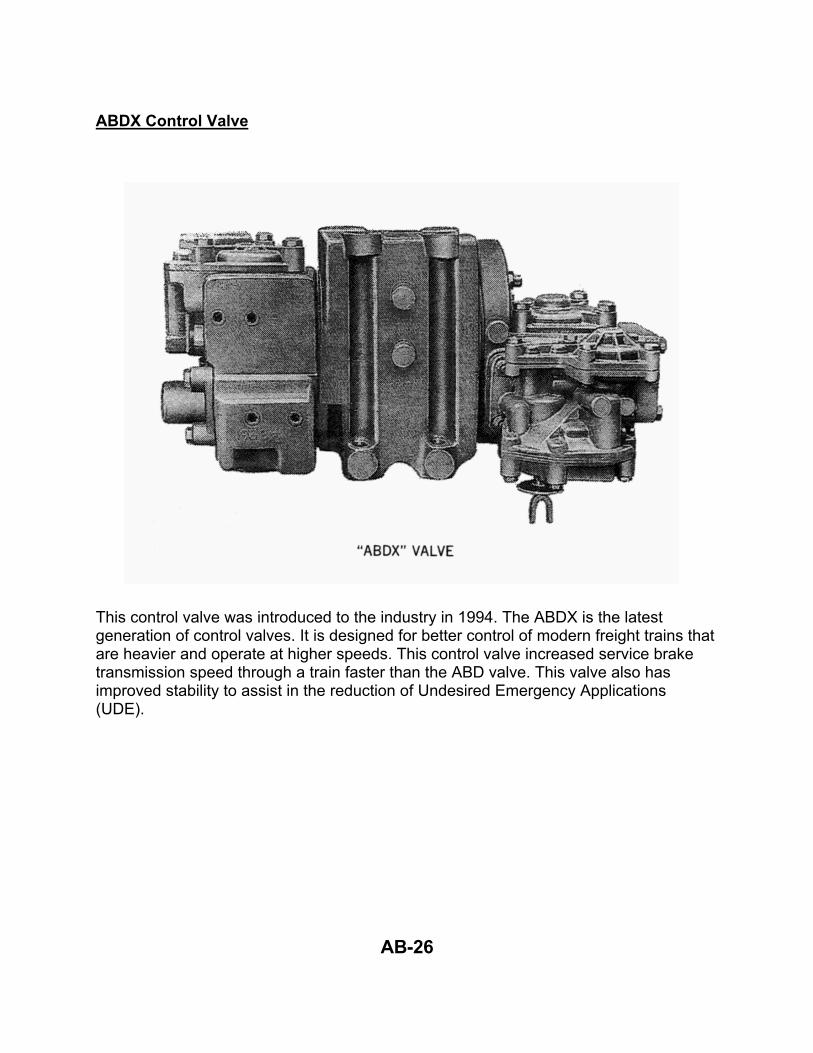
ABDX Control Valve
This control valve was introduced to the industry in 1994. The ABDX is the latest generation of control valves. It is designed for better control of modern freight trains that are heavier and operate at higher speeds. This control valve increased service brake transmission speed through a train faster than the ABD valve. This valve also has improved stability to assist in the reduction of Undesired Emergency Applications (UDE).

AB-27
DB-60 Control Valve
The DB-60 control valve was introduced to the industry in 1994. This valve is manufactured by New York Air Brake Company and has features similar to the ABDX. It also has the increased transmission speed of the ABDX. The DB-60 valve utilizes poppet valves instead of slide valves to control the brakes.

AB-28
RESERVOIRS ON A FREIGHT CAR Auxiliary Reservoir This is a 2500 cubic inch (10.5 gallon) reservoir. Air in this reservoir is directed, by the control valve, into the brake cylinders during a service brake application. Emergency Reservoir This is a 3500 cubic inch (15.5 gallon) reservoir. During emergency brake applications, this reservoir combines the auxiliary reservoir to give an increase in brake cylinder pressure. Also, during release of the brakes, this reservoir helps recharge the auxiliary reservoir or the brake pipe depending on the type of control valve used. Brake Cylinder This is a cylinder of 630 cubic inches (2.7 gallons) in which air from the auxiliary and emergency reservoir acts on a piston which transmits force to the brake rigging. Retainer Valve Air from the brake cylinder exhausts through this valve during a brake release. This valve, when properly set, will retard or prevent brake cylinder exhaust after a release while the auxiliary reservoir, emergency reservoir and brake pipe are being recharged. Most retainer valves have three positions. They are:
x EX-Exhaust - Vertical downward. This is normal or direct exhaust and will exhaust all air in brake cylinder quickly.
x HP-High Pressure - 45 degrees below horizontal. Will retain 20 lbs. of air in brake cylinder..
x SD-Slow Direct Exhaust - 45 degrees above horizontal. This position will exhaust all air in brake cylinder in about 87 to 90 seconds.
When Is the Air Brake System Charged? The entire brake system is considered fully charged when the auxiliary reservoir and emergency reservoir are charged to the same value as the brake pipe - regardless of the pressure. The pressure on the head car should be almost the same as the feed valve setting on the locomotive and then tapering no more than 15 pounds to the rear of train. Feed valve settings are listed in the NS-1 Rules for Equipment Operation.

AB-29
What Causes the Brakes to Apply? To apply the brakes, the air in the brake pipe must be reduced. Any time the brake pipe is reduced three pounds or more below the auxiliary reservoir pressure, the control valve will allow a volume of air to flow from the auxiliary reservoir into the brake cylinder. How Much Brake Cylinder Pressure Can Be Developed? The least amount of brake cylinder pressure that can be developed is ten pounds. This is caused by a minimum brake pipe reduction of six to eight pounds or less. The control valve is so designed that it recognizes a brake pipe reduction as small as three pounds. When the control valve recognizes this small reduction, it will go into a quick service movement. With this quick service, each car throughout the train will reduce the brake pipe six to eight pounds depending on the length of the car. This reduction is enough to cause at least a ten-pound brake cylinder pressure. So bear in mind that no matter how small the reduction (three pounds or more), it will always cause at least a ten-pound brake cylinder pressure. After the initial ten-pound brake cylinder application, caused by the quick service action on each car, any further brake pipe reduction will cause an equal amount of air to flow out of the auxiliary reservoir through the control valve into the brake cylinder. Since the auxiliary reservoir is nearly four times as large in area as the brake cylinder, each pound of air leaving the auxiliary reservoir (after first service) will develop two-and-a-half pounds of pressure in the brake cylinder. This transfer of air from the auxiliary reservoir will continue until the brake pipe has been reduced enough to cause the brake cylinder and auxiliary reservoir to equalize. This is all the braking pressure that can be obtained with a service brake application. This equalization can be obtained by reducing the amount of brake pipe pressure on each car by approximately 30%. The brake pipe pressure on the rear car will be somewhat lower than the head car, maybe as much as 15 pounds. In order to cause the brakes on all cars to equalize or go to full service, the rear car as well as the head car must have the brake pipe pressure reduced by 30%. So, if the rear car is at 75 pounds, you would need to reduce brake pipe pressure by 22.5 pounds or lower it to 52.5 pounds. There are two methods to accomplish this. One, watch the head of train device until the pressure on rear drops 30%. Two, reduce the brake pipe pressure on the head end by 35 pounds. This will leave 55 pounds of air in the brake pipe, which is important and will be discussed later, and will cause all of the brakes in the train to be applied to full service (equalization). With 55 pounds on the head end (the rear can't be higher), you will have 55 pounds or less on the rear. This will cause equalization. After equalization of the brake cylinder and auxiliary reservoir is obtained on each car, the

AB-30
only way we can obtain more brake cylinder pressure is by causing an emergency brake application. An emergency brake application is caused by venting the air out of the brake pipe at a very rapid rate. The control valve at each car senses this very rapid drop in brake pipe pressure and acts to combine the emergency reservoir (which is still charged to its original valve) and the auxiliary reservoir. Now the auxiliary reservoir is again higher than the brake cylinder and will increase the brake cylinder pressure approximately 20%. In order to obtain an emergency brake application, we must have a sufficient amount of brake pipe pressure. To make the brakes apply in emergency, we should have at least 35 pounds brake pipe pressure. Below this value, the exhaust may not be rapid enough to cause an emergency brake application.

AB-31
Brake Chart.

AB-32
How Long Does it Take Brakes to Apply? The amount of time it takes to apply the brakes throughout the train depends on the length of the train and type of control valves. When making a service application, air travels through the brake pipe at a minimum of 500 feet per second. For example: Let us apply the brakes on a 50-car train, each car being 50-feet in length. Lower the brake pipe at either end six to eight pounds. This causes each car to reduce the brake pipe locally six to eight pounds. This signal for each car to reduce the brake pipe locally travels through the train at 500 feet per second. The brakes on the first car would begin to apply immediately but would take about 25 seconds to build up to a 10-pound pressure. It would be five seconds before the 50th car received the signal, then would take the same amount of time to build up brake cylinder pressure as car number one. Let us apply the brakes on the same 50-car length with a 15-pound brake pipe reduction. The first six to eight pounds of the reduction would be exhausted locally at each car. The remainder of the reduction would have to travel to and exhaust at the point the reduction was made on AB or ABD control valves. The brakes on the first car would start applying immediately but would take about 30 seconds to build up to a maximum pressure of 38 pounds. The rear car would take about five seconds to start applying; and since the air for the second half of the reduction must travel to and exhaust at the point of reduction, it would possibly take 35 seconds to build up the same amount of brake cylinder pressure on the rear car as on the first car. Any greater reduction would cause a higher brake cylinder buildup until equalization was obtained. So, we could safely say that the longer the train and the heavier the application, the longer it would take to fully apply brakes on the entire train. How long does it take the brakes to apply in emergency? When we apply the brakes with an emergency brake application, air for the emergency signal travels through the train at approximately 900 feet per second. Let us apply the brakes in emergency on a 100-car train by separating the air hoses between the locomotive and the first car. The air immediately rushes to the atmosphere and causes the control valve on the head car to go to emergency. The control valve on each successive car goes into emergency. The brakes on the head or first car would start applying immediately but would take nine seconds to build to full brake cylinder pressure (approximately 77 pounds, with a fully-charged system carrying
AB-33
How long does it take the brakes to apply in emergency? (Cont'd) 90-pound brake pipe). During the first 1-1/2 seconds after an emergency is recognized by the control valve, a 15-pound brake cylinder pressure is obtained. During the next four seconds, the brake cylinder pressure builds up to 45 pounds. Then it builds to maximum during the last 3-1/2 seconds. This emergency application advances through the train at 900 feet per second. About 5-1/2 to 6 seconds after the brakes start applying on the first car, they begin to apply on the 100th car, and then would take nine seconds to develop full brake cylinder pressure. For brakes to fully apply in emergency on a 100-car train, 15 seconds is a good average. What Does it Take to Release the Brakes? In order to get the brakes on a car to release, we must raise the brake pipe pressure higher than the auxiliary reservoir pressure. Cars equipped with AB valves or newer will start releasing when the brake pipe pressure is only 1-1/2 to 2 pounds higher than the auxiliary reservoir pressure. How Long Does it Take to Release the Brake on a Train? This depends on the length of a train and the amount of brake pipe reduction made. Let's take, for example, a 50-car train carrying 90 pounds of brake pipe pressure. To cause the brakes on this train to apply with a full service brake application would take about a 26-pound brake pipe reduction. The brake pipe, auxiliary reservoir, and brake cylinder would equalize at approximately 64 pounds. Should we release the brakes when equalization is reached, we would only have to raise the brake pipe pressure 1-1/2 to 2 pounds to get them to release on the first car. This wave of air or signal would travel to the end of 50 cars in about five seconds on AB brakes or about four seconds on ABD or newer brakes because of accelerated release.

AB-34
Application without Recharging What happens when brakes are applied more than once without giving the system time to recharge? We know that the brake pipe pressure can be restored before the auxiliary reservoir pressure. This is apparent when watching the air gauges on the lead unit of locomotive. If we have made a 15-pound brake reduction from a 90 pound brake pipe, there would be a 75-pound auxiliary reservoir pressure and approximately 28-34 pound brake cylinder pressure. Since it is necessary to restore only part of the 15 pounds, (1 1/2–2 pounds), to release the brakes, it is possible to have 90 pounds brake pipe pressure indicated on the lead unit gauges but auxiliary reservoir pressure remains lower because the system has not fully recharged. If, at this time, a second brake application should be made, the brakes may fail to apply unless brake pipe pressure is again reduced below auxiliary reservoir pressure. Since the auxiliary reservoir is not fully charged at this time, less brake cylinder pressure is obtained than would be the case with a fully charged auxiliary reservoir. This same differential in pressure occurs every time the brakes are released and again applied. Should release and reapplication occur often enough without allowing recharging time, the result could be a shortage of air pressure in the auxiliary reservoir. When necessary to reapply the brakes before the air system is recharged, we must ensure that brake pipe pressure again falls below auxiliary reservoir pressure by at least 3 pounds at the proper rate. NS-1 requires any subsequent brake pipe reduction be 5 pounds greater than the total amount of the last reduction in order to activate the quick service feature of the control valve. In the above example, a 15 pound reduction was made: this would require a 20 pound initial reduction if the brakes had to be reapplied before the air system was properly recharged.

AB-35
26L Air Brake Equipment Found on Road Locomotive units in service on the Norfolk Southern System.
(Double Heading Cock)

AB-36
The 26L brake equipment consists of two or three air gauges and the amp gauge. Example I
Some locomotives have two duplex air gauges and a flowmeter. They will be identified as left and right gauge and flowmeter.

AB-37
Main Reservoir This is the red pointer on the left gauge. It represents the pressure in two large reservoirs. These reservoirs supply all air-operated devices on the locomotive unit. All air for the locomotive unit is furnished by an air compressor. This compressor will unload by a pressure switch. It is usually set to unload when the main reservoir pressure reaches 140 pounds and load again when main reservoir pressure drops to 125-128 pounds. Once the main reservoir system is charged, it will fluctuate between 125 and 140 pounds. Should the unloading switch fail to operate, there is a safety valve set to pop off at 150 pounds to relieve the pressure. In charging the main reservoir system, any time the pressure is less than 15 pounds above regulating valve setting, it would be advisable to center the reverser of the locomotive, open the generator field switch, and speed the engine up to an intermediate throttle position to make the air compressor supply air faster on some locomotives. You should continue this operation until the main reservoir pressure is 15 pounds higher than regulating valve setting. It is a waste of fuel to continue revving the engine if main reservoir is 15 pounds higher than regulating valve setting. On some EMD locomotives the engine speed will automatically go to No. 2 or No. 3 throttle anytime the main reservoir pressure drops below 120 pounds. On GE Dash 8 and Dash 9 locomotives advancing the throttle to number 1 will give maximum air compressor speed. Any further advancement of the throttle will cause the air compressor speed to decrease. Equalizing Reservoir This is the white pointer on the left gauge. It represents the amount of air in a 220 cubic inch (approximately three quarts) reservoir and a small volume of air on the relay valve of the automatic brake valve. The function of this reservoir is to control the amount of brake pipe reduction. For instance, if we were going to make an automatic brake application of 15 pounds, we would move the automatic brake handle and cause the equalizing reservoir to reduce 15 pounds. This would only take a couple of seconds as a very small volume of air is exhausted. The brake pipe air would reduce to this value. The volume of air in the brake pipe is very large (330 gallons) on a 100-car train, and it would take 15-30 seconds for this volume to exhaust and would be very difficult to measure. So, we use equalizing reservoir gauge in making all service brake applications because the brake pipe is controlled by the equalizing reservoir. If we lower the equalizing reservoir, the brake pipe will reduce accordingly. If we raise the equalizing reservoir, the brake pipe will raise accordingly.

AB-38
The only instance when the equalizing reservoir does not control or lead the brake pipe is during an emergency brake application or when the brake valve cut-off valve (Double Heading Cock) is cut out. If the emergency brake application was caused by moving the automatic brake valve to the emergency position, the brake pipe would reduce to zero immediately; and the equalizing reservoir would follow at a much slower rate. The equalizing reservoir would take approximately 15 seconds to reduce to zero. If the emergency brake application was caused by a train separation or burst air hose, or other unknown reason, the brake pipe would immediately reduce to zero; but the equalizing reservoir would not be affected. Brake Pipe This is the white pointer on the middle or right gauge. It measures the amount of brake pipe pressure at the automatic brake valve on the lead unit. It does not necessarily measure the brake pipe pressure on an intermediate or rear car of a train. Although the brake valve will attempt to supply an equal pressure throughout the train, resistance to air flow in the brake pipe would cause this gauge to show full pressure long before this same pressure is obtained on cars farther back in the train and may never reach this same value on the rear of the train. This difference in pressure on the locomotive or head end of the train and the rear is referred to as brake pipe gradient and should not exceed 15 pounds. Locomotive Brake Cylinder This is the red pointer on the middle or right gauge. It represents any pressure in the brake cylinder, on that unit regardless of how it is applied. The brakes on the locomotive will apply two ways. Any time the brake pipe pressure is reduced, or is reducing, the locomotive brakes will apply. This pressure will show on the brake cylinder gauge. The locomotive brakes will also apply any time the independent brake is placed in the applied position. This pressure would also register on the brake cylinder gauge.

AB-39
Flow Meters
OLD TYPE NEW TYPE Most locomotive units equipped with 26L brakes have flow meters. Its purpose is to indicate air flow through the automatic brake valve into the brake pipe. These are two of several types of flow meters. On newer units the flow meter will be in place of the right gauge, and on older units it will be on top of the console or integrated in the IFC or ICE screens. The flow meters have numbers or marks which do not necessarily indicate air pressure in pounds. We have two pointers - black and red on some flow meters and white and red on others. The black or white pointer is controlled by the amount of air flowing through the brake valve. The red pointer is controlled manually by the engineer. We also have a small pilot light which lights up and stays lit as long as air flow through the brake valve exceeds a predetermined setting. When we first couple to a train and cut the air in, the brake pipe on the train is empty or practically empty and takes a lot of air to charge it. The flow indicator hand on the flow meter will swing to the right and the pilot light will come on if equipped. As the brake pipe fills with air, it will demand less air to supply it; so the flow indicator will start moving back to the left, merely indicating that not as much air is moving through the brake valve to the brake pipe. The higher the brake pipe becomes charged, the further to the left (or lower) the flow indicator moves. On flow meters equipped with a pilot light, the light will go out when the black hand (flow indicator) returns to about No. 4 on the gauge. The

AB-40
pilot light will remain out unless the rate of air flow increases enough to cause the black hand to move higher than No. 4 position on the gauge. We can use the flow meter to determine when brakes in the train are released. After a brake pipe reduction has been made and released, the flow meter's indicator will move to the right and the pilot light will come on. A good way to determine when brakes in the train have released is when the indicator returns to near where it was before the brake application. On some trains, especially in cold weather, the indicator will stay on a high mark (indicating a high rate of flow) and the pilot light, if equipped, will remain on for long periods of time after the brakes have been released. This does not necessarily mean you have brake trouble. It simply means it is taking a lot of air to keep the brake pipe charged. To determine if a leak has developed in the brake pipe after it is fully charged and the indicator falls to a low mark, manually adjust the red pointer barely to the right of the black or white (depending on type) one. If and when the black or white pointer passes the red one, or the indicator rises suddenly, it will indicate that it is now taking more air to supply the brake pipe and possibly a leak has developed. On flow meters equipped with a pilot light, if the black or white indicator moves to the right past the No. 4 mark, the pilot light will come on as a warning of the leak. Automatic Brake Valve The automatic brake valve is a self-lapping and pressure-maintaining brake valve. This brake valve is designed for panel mounting resulting in only the brake valve handle and cut-off pilot valve (double heading cock) being visible on the face of the panel.

AB-41
Positions of the Automatic Brake The 26L automatic brake valve has six positions. The six positions arranged left to right are Release, Minimum or First Service, Full Service, Suppression, Handle Off and Emergency. Release Position When the brake handle is in the extreme left position on the quadrant, it is in release position. This position is for charging the brake pipe and for releasing the locomotive and train brakes. Minimum or First Service Position This position is against the first raised portion to the right of the release position. Moving the handle to this position causes a minimum brake pipe reduction of six to eight pounds.

AB-42
First Service Zone The first SERVICE ZONE consists of a sector of handle movement on the quadrant from the minimum service position to full-service position. Movement of the handle to the right in this zone will reduce the brake pipe proportionately to the amount of movement until a 23 to 26 pound reduction is made in the full service position. The 26L brake will automatically lap and maintain the brake pipe pressure at any point that the movement of the handle is stopped. Full Service Position This position is at the extreme right of the service zone next to, but not against, the second raised portion of the quadrant. Moving the handle to this position will result in a 23 to 26 pound brake pipe reduction, which is enough to cause the locomotive brakes to fully apply. Suppression Position This position is against the second raised portion of the quadrant immediately beyond the full service position. In addition to providing for a 23-26 pound brake reduction, recovery from a penalty brake application is obtained. Second Service Zone The raised portion to the right of the suppression position is a continuation of a service zone and is used when it is desired to lower the brake pipe beyond the 23-26 pound reduction. This second service zone will reduce the brake pipe pressure proportionately with handle movement from a 23 to 26 pound reduction to 10 pounds if the handle is moved all the way to the handle off position.

AB-43
Handle-Off Position This position is located in the first notch beyond the suppression position. In this position, the equalizing reservoir will be reduced to zero and the brake pipe will be reduced to ten pounds pressure. The brake valve handle is always placed in this position on trailing units. The handle is normally removable in this position; however, on most locomotive units the automatic brake valve handles are pinned in place and cannot be removed. Emergency Position This position is located to the extreme right of the brake quadrant. It is used when it is desired to make an emergency brake application with the automatic brake valve. It is also used for recovering the brake valve after an emergency brake application from any source. In this position the brake pipe is reduced immediately to zero.

AB-44
Portions of the Automatic Brake Valve

AB-45
A. Brake Valve Cut-Off Valve (Double Heading Cock) The handle of the cutoff pilot valve is visible on the face of the automatic brake valve. For simple railroad language, we will refer to this cutout cock as the double heading cock. We use this device for cutting in and cutting out the automatic brake valve. There are two and three-position cutoff pilot valves (double heading cocks). On Norfolk Southern locomotive units, you will find only the two-position type. On divisions where foreign line locomotive units are operated, the three-position type may be encountered. The three positions are: Freight or In: In this position the brake valve is cut in and will control the brake
pipe with movement of the brake handle. Out: The brake valve is cut out and will not control the brake pipe. In this
position, the maintaining feature of the brake valve is eliminated. Passenger: In this position, the brake valve is cut in. This position was
designed for use on passenger trains and the release can be graduated. This could cause a premature or accidental release of the air brake. The cutoff pilot valve should not be used in this position.
B. Regulating Valve/Feed Valve This is a self-lapping type regulating valve which is operated by a service cam fastened to and rotated by the automatic brake valve handle. This valve regulates the pressure developed in the equalizing reservoir. Adjustment of the equalizing reservoir pressure can be made by turning the adjusting screw of the regulating valve. This is fastened to a knob located on the left side of the automatic brake valve. This knob is commonly called the feed valve. To increase the pressure, turn the knob clockwise; to lower the pressure, turn the knob counterclockwise. Movement of the automatic brake valve handle into the service sector causes the regulating valve to reduce the equalizing reservoir to a value in proportion to the handle movement until a complete reduction of the equalizing reservoir is obtained when the brake handle is placed in the handle-off position.

AB-46
A synopsis of the above statement is that once the regulating valve is set with the automatic brake valve handle in the release position, each time the brake valve handle is moved away from the release position, we change the value of the setting. C. Relay Valve Portion This portion consists of a diaphragm-operated relay valve. This valve's purpose is to cause the pressure in the brake pipe to equal that of the equalizing reservoir. It will either reduce the brake pipe pressure or supply the brake pipe according to the value of the equalizing reservoir. This brake pipe pressure is used to charge the brake system on the locomotive as well as cars in the train. On one side of the diaphragm mentioned above we have equalizing reservoir pressure; on the opposite side we will have brake pipe pressure. These two pressures will tend to be equal. Reducing the equalizing reservoir pressure will result in a like amount being exhausted from the brake pipe side until the two sides are equal. This is why we say the 26L automatic brake valve is a self-lapping brake valve. Should a leak occur in the brake pipe, the supply port would automatically open to bring the brake pipe pressure equal to the equalizing reservoir. This is why we call this brake valve a self-maintaining brake valve. D. Brake Pipe Cutoff Valve This valve cuts off brake pipe air leaving the automatic brake valve. This valve will go to the cut-off position in the following ways: (1) By turning the brake valve cut-off valve (double heading cock) to the out
position. (2) When an emergency brake application occurs on the locomotive from any
source. E. Vent Valve This valve is cam operated from the brake valve handle shaft. When the automatic brake valve handle is placed in the emergency position, all the air in the brake pipe is vented very rapidly through this valve to the atmosphere.

AB-47
F. Emergency Valve This valve is cam operated by placing the automatic brake valve handle in the emergency position. This valve has three functions: (1) Provides for tripping of the P.C. switch. (2) Vents all equalizing reservoir pressure to the atmosphere. (3) Recharges the device necessary to recover from an emergency brake
application. We will discuss this device later. G. Suppression Valve This valve is also cam operated. When the automatic brake valve is placed in the suppression position or at any point on the quadrant to the right of the suppression position, the suppression valve allows main reservoir to recharge the application reservoir back to normal after a penalty application. It also acts to reset the auxiliary device that caused the brakes to apply when the application reservoir dropped to approximately brake pipe pressure. We will discuss this device later. H. Equalizing Reservoir Cutoff Valve This valve is affected by the position of the brake valve cutoff valve (double heading cock) and the position of the automatic brake valve handle. When the double heading cock is turned to freight or in position, this valve will be open only when the automatic brake valve is in the release position. Movement of the automatic brake valve handle away from the release position closes this valve and lowers the equalizing reservoir pressure. The only way we can restore any equalizing reservoir pressure is by placing the brake valve handle in the release position. Then the valve opens and equalizing reservoir pressure will be restored to the regulating valve (feed valve) setting. The brake pipe will follow and release the brakes. When the brake valve cut-off valve (double heading cock) has three positions and is positioned in the passenger position, this valve (equalizing reservoir cut-off valve) is held open at all times. Movement of the automatic brake valve handle away from the release position into the service sector will cause the equalizing reservoir pressure to reduce in proportion to the movement until the brake pipe is completely exhausted (this is controlled by the relay valve). However, movement of the brake handle toward the release position would cause the equalizing reservoir pressure to rise proportionately to the handle movement until it would be completely restored in the release position.

AB-48
Since the brake pipe pressure will raise and lower along with the equalizing reservoir, restoring the equalizing reservoir pressure two or three pounds would result in the brake pipe raising a similar amount, which would result in an accidental release of the brakes on freight trains. Independent Brake Valve This brake valve is located on the front of the control stand, below the automatic brake valve, and provides for independent control of the locomotive brakes regardless of the brake pipe pressure. The independent brake valve has two positions: -- Release: This is when the handle is at the extreme left. -- Applied: Movement to the right causes the locomotive brake cylinder
pressure to build up in proportion to the movement until a full application is obtained with the handle in the extreme right position. Stopping the handle at any point in the application zone causes the independent brake valve to lap and maintain the application.
Bailing off or depressing the independent brake valve handle in any
position will result in releasing all locomotive brake cylinder pressure developed as a result of a brake pipe reduction or an automatic brake application.

AB-49
MU-2-A Valve OR Two-Position Cutout Cock This device is used to cut in or cut out the independent brake valve. MU- 2-A Valve Two-Position Cutout Cock On Norfolk Southern locomotive units, some will have three positions; others will have two. -- Lead or Dead Position: In this position the brake valve is cut in. The
independent brake valve will control the brakes of the locomotive. -- Trail 6, 26, or Trail 24: Either of these two positions will cut the
independent brake valve out. The MU-2-A valve is set in one of those positions any time the unit is trailing in a consist. With the MU-2-A valve set in any of the trail positions, the independent brake valve cannot control the brake cylinder pressure.

AB-50
Control Valve We use either a Westinghouse or New York Air Brake 26F control valve. It will be located underneath the crew cab floorboard. This control valve provides for application of the locomotive brakes when we have a brake pipe reduction or release of the locomotive brakes when the brake pipe pressure is restored.

AB-51
Portions of the 26F Control Valve The 26F control valve consists of three portions: Pipe Bracket: This is the part that all the pipes are connected to. Service Portion: The service portion of the 26F control valve will cause the brake on the locomotive unit to apply any time the brake pipe pressure is being reduced for any reason. It will also cause the brakes to release when brake pipe pressure is restored. The service portion is capable of distinguishing between a service or emergency application, not by rate of reduction but by the amount of reduction. It contains two pressure-limiting valves. One limits the amount of pressure in the 16 pipe (which goes to the J-Relay valve) during a service brake application and the other limits the amount of pressure in the 16 pipe anytime brake pipe pressure goes under 20 pounds. The setting of the valve limiting a service brake can be adjusted; the other cannot. The service-limiting valve is set to give 58 pounds brake cylinder pressure if brake handle is placed in full service position. The service portion of the 26F control also provides for charging reservoirs necessary to furnish proper brake operation, namely, auxiliary reservoir. Air leaving this reservoir during a brake pipe reduction goes into the 16 pipe to the J-Relay valve, causing brake cylinder pressure to be developed on the locomotive unit. Quick Release Portion: This portion provides for the release of any locomotive brake cylinder pressure developed as a result of a brake pipe reduction. This is accomplished by bailing off or depressing the independent brake valve handle. Any time a brake pipe reduction is made, the independent brake valve handle must be depressed if the locomotive brakes are to be kept from applying.
AB-52
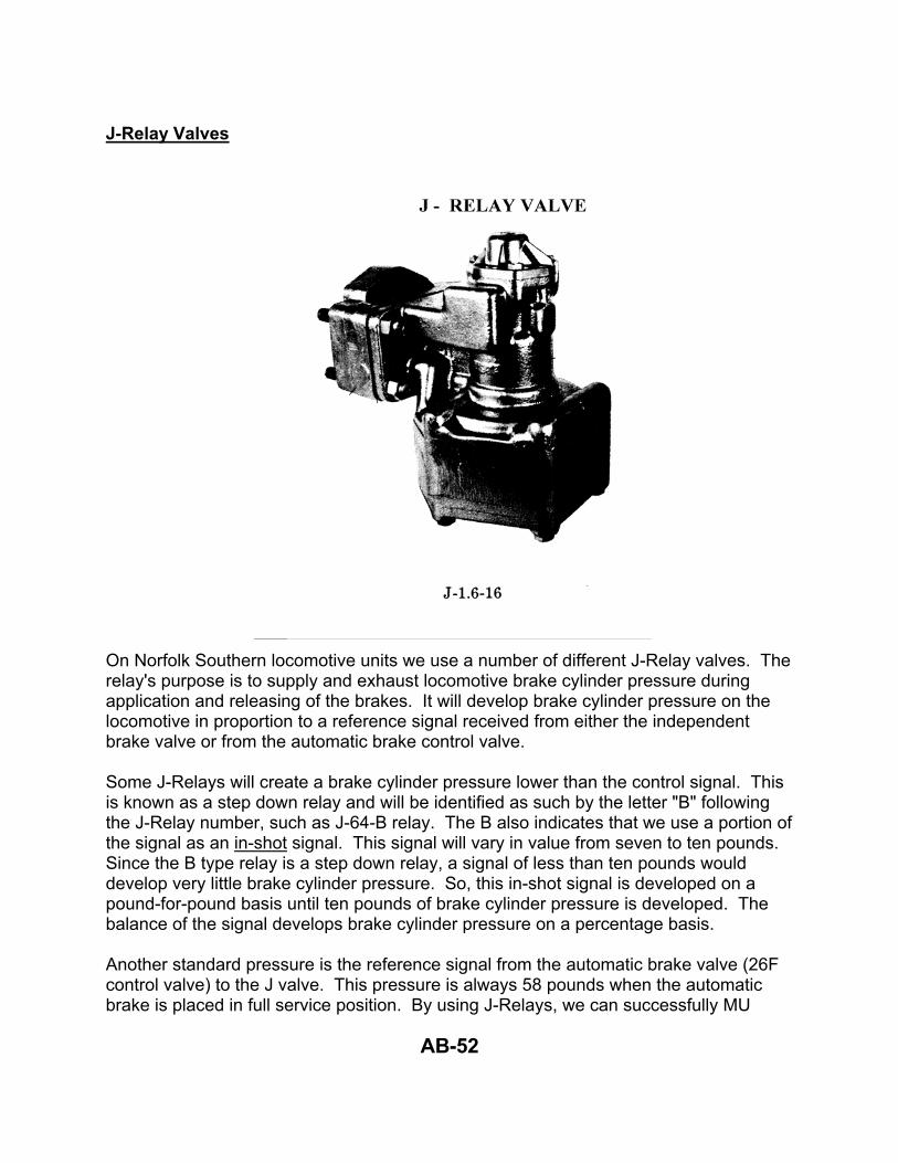
J-Relay Valves On Norfolk Southern locomotive units we use a number of different J-Relay valves. The relay's purpose is to supply and exhaust locomotive brake cylinder pressure during application and releasing of the brakes. It will develop brake cylinder pressure on the locomotive in proportion to a reference signal received from either the independent brake valve or from the automatic brake control valve. Some J-Relays will create a brake cylinder pressure lower than the control signal. This is known as a step down relay and will be identified as such by the letter "B" following the J-Relay number, such as J-64-B relay. The B also indicates that we use a portion of the signal as an in-shot signal. This signal will vary in value from seven to ten pounds. Since the B type relay is a step down relay, a signal of less than ten pounds would develop very little brake cylinder pressure. So, this in-shot signal is developed on a pound-for-pound basis until ten pounds of brake cylinder pressure is developed. The balance of the signal develops brake cylinder pressure on a percentage basis. Another standard pressure is the reference signal from the automatic brake valve (26F control valve) to the J valve. This pressure is always 58 pounds when the automatic brake is placed in full service position. By using J-Relays, we can successfully MU

AB-53
locomotive units designed to use different brake cylinder pressures. A standard reference signal to the relay valve is created in the independent equalizing or application and release pipe. If we could put a gauge in this pipe, it would read 45-pounds pressure when the independent brake is fully applied. Some of the J-Relay valves used on Norfolk Southern are: J-64-B Relay The J-64-B relay is used on some SW-15, GP-38, and some other locomotive units with 32-pound brake cylinder pressure that use clasp type brake shoes. J-84-B The J-84-B relay is used on some former Conrail locomotives (mostly six axle). These locomotives will have 36 pounds independent brake cylinder pressure and approximately 28 pounds pressure when the automatic brake is applied full service. J-14 Relay Valve The J-14 relay valve is used on locomotive units that are equipped with clasp type brakes with composition brake shoes. These brakes are very effective; therefore, less pressure in the brake cylinders is needed to have the same stopping power as a single shoe system. J-14 relay valves are mostly used on new units such as C36-7, some SD40-2, SD50, C30-7. These locomotive units will have 45 pounds independent brake pressure and 23 pounds pressure when automatic brake is placed in full service position. J-1.4-14 Relay Valve We use this type relay on U-23-B, U-30-B, locomotive units. These units will have 63 pounds independent brake pressure and 58 pounds pressure when automatic brake is placed in full service position.

AB-54
J-1.6-16 Relay Valve The J-1.6-16 relay valve is used on GP-38-2, GP-50, GP-60, SD-40, SD-50, SD-60, Dash-8 and Dash-9 locomotive units. These units would only have brake shoes on one side of the wheels. This is why we use the high brake cylinder pressure. These locomotive units will have 72 pounds independent brake pressure and 58 pounds pressure when automatic brake is placed in full service position. J-1 Relay Valve The J-1 Relay valve is the simplest of the relay valves. It has a single diaphragm and will develop an output pressure identical to the input or pilot pressure. This relay valve is used on some former Conrail locomotives (mostly four axle locomotives). These locomotives will have 45 of independent brake pressure when the independent brake is applied fully and 58-60 pounds pressure when the automatic brake is placed in the full service position.

AB-55
P-2-A Brake Application Valve This valve functions automatically in operation of the safety control (crew call, alerter, auto train stop (ATS), locomotive speed limiter (LSL), or dead man pedal to give a penalty brake application. Air in the application chamber is automatically maintained at main reservoir pressure if; - The P-2-A has not tripped. Should the engineer fail to reset the alerter, crew call, or any other safety device, air in the application chamber would start venting to the atmosphere. This venting is through chokes and whistles or an electronic audible alarm to give the engineer warning that the application chamber is exhausting.

AB-56
This venting of air starts with the application chamber at main reservoir pressure; and when it lowers to near brake pipe pressure, the P-2-A brake application valve acts to cause the brakes on the locomotive to apply at a service rate. Since this air from the application chamber is vented slowly through a choke, it usually takes five or six seconds for the chamber to reach the brake pipe setting. So, any time the engineer will correct whatever is causing the application chamber to exhaust, such as resetting the crew call or alerter, he stops the exhaust of the application chamber, the pressure returns to main reservoir pressure, and a brake application will not be received. So, whenever we hear a whistle blowing and application air is venting, we have about six seconds to correct the cause. If we do not correct the cause, the application pressure will vent to near brake pipe pressure, at which time the P-2-A valve will cause a penalty to occur and:
- Activate the P.C. switch. This causes the locomotive unit’s RPM to return to idle and also unloads the generator or alternator and;
- Equalizing reservoir will start reducing at a service rate with the brake handle in the release position. Remember the brake pipe will also be reducing at the same rate.
The amount the equalizing reservoir reduces will depend on the locomotive unit you are operating. On some locomotives, the equalizing reservoir will exhaust 25 pounds at a service rate and the exhaust will stop; on other locomotive units, the equalizing reservoir will exhaust to zero pressure. Instructions are that when a penalty brake application is received, the train must be brought to a stop. If a penalty is received the engineer should move the automatic brake handle to suppression position as soon as the air starts exhausting. After the train is stopped and the P.C. light goes out, release the brakes and proceed. Note: On some locomotive units the automatic brake may have to be released before the P.C. light will go out. On all units the throttle must be placed in idle for the P. C. light to go out.

AB-57
A-1 Charging Cutoff Pilot Valve
A-1 CHARGING CUT-OFF PILOT VALVE This valve is used for break-in-two protection on locomotives. When a train or locomotive separates and causes brake pipe air pressure to reduce at a rate faster than a service rate, the A-1 charging cutoff pilot valve comes into action and performs the following functions: 1. Cuts off the flow of brake pipe air from the automatic brake valve on the
lead unit if equipped with 26L brakes.
2. Trips the P.C. Switch.
On locomotive units equipped with the 20-second delay on the P.C. switch, Item 2 is activated by the delay device instead of the A-1 charging cutoff valve.

AB-58
To reset the A-1 charging valve after an undesired emergency brake application, the automatic brake valve must be placed in the emergency position and left a sufficient amount of time. When the brake handle is placed in the emergency position and the equalizing reservoir reaches zero, the A-1 charging valve should be recharged. The automatic brake handle can now be returned to release position after pausing in handle-off position to recover the PC switch. On some locomotive units with 20-second delay, the PC light will not go out until brake is released, and brake pipe pressure is partially restored. Anytime there is an emergency brake application, either desired or undesired the automatic brake handle must be placed in the emergency position as soon as the P. C. switch activates or until the train stops.

AB-59
Electro-Pneumatic Locomotive Brake Systems The 26L brake equipment you have learned about came into service in the mid-1960s and is still available for installation on current production locomotives. The advent of microprocessors (mini-computers) made it possible to use electronics to perform many of the functions that are performed mechanically on 26L equipment; this led to the development of electro-pneumatic (EP) brake systems. Norfolk Southern, as well as all other major railroads, starting buying EP-equipped locomotives in the 1990s. EP brake systems rely heavily on electronics to do the same thing as the 26L equipment you have just learned about; as a result the number of parts have been greatly reduced. EP brake systems do everything 26L equipment does, but they do it without the A1 Charging Cutoff Valve, P-2-A valve, MU-2-A valve, 26F control valve, J-Relay valve, and valve assemblies of the automatic and independent controls which all have been replaced by modern electronic assemblies. Because EP brake systems are electronically-based, they must have electrical power to completely function. As a result, EP-equipped locomotives have one or more air brake circuit breakers. Older (non-EP) units do not have air brake circuit breakers. The number and location of the air brake circuit breakers depends on the locomotive manufacturer and the type of brake equipment. Norfolk Southern uses EP brake equipment made by two companies. CCB II (Computer Controlled Brake Model II) is made by New York Air Brake. EPIC (Electro Pneumatic Integrated Control) is made by WABCO (Westinghouse Air Brake). Instead of automatic and independent brake valves, EPIC and CCB II both use controllers. The controller handle positions and functions are the same as 26L equipment. CCB II Controller EPIC Controller
Handle positions are the same as 26 brake valve

AB-60
Both EPIC and CCB II use Main Reservoir, Equalizing Reservoir, Brake Pipe, and Locomotive Brake Cylinder pressures. Both systems also use a flow meter. Locomotives equipped with CCB II and EPIC do not have duplex air gauges. Air pressures are shown on electronic display panels that also show other information such as speed and traction motor current. The double heading cock and MU-2-A valve functions also are on the panels. You will learn about them in the lesson “Preparing Locomotives For Service”.
The display panel system on General Electric locomotives is called “Integrated Function Display” (IFD). A GE IFD panel is shown to the left. Air pressures are shown in the upper left part of the screen.
The EMD display system is called “Integrated Cab Electronics” (ICE). The ICE panel that shows air pressures is called the Locomotive Display screen. Air pressures are shown in the upper left part of the screen. An ICE Locomotive Display screen is shown at the right.

AB-61
“Desktop” Type Brake Handle Arrangement EPIC, CCB II, and 26L automatic and independent controllers also come in what is known as a “desktop” or “30 style” configuration. In locomotives equipped with these type controllers, the independent brake handle is on the right and the automatic brake handle is on the left. Instead of moving left to right like on a 26C brake valve, the automatic and independent handles move front to back; but there is no difference between the functions and positions of the automatic or independent handles. Automatic Independent Handle Handle
Release position is all the way toward the engineer. Emergency position is all the way forward.
Release position is fully toward the engineer. The indepen-dent is fully applied when the handle is all the way forward. To bail off, push the handle to the right.
CCB II Desktop/30 Style
Controller

AB-62
CCB II ER Target Window The “ER Target” window is found only on CCB II, and is located on the controller above the automatic brake handle. The number in the ER Target window is a “Command” that sets equalizing reservoir pressure based on the automatic handle position.
The purpose of the ER Target window is to avoid brake pipe overreductions when using the automatic brake. With 26L and EPIC equipment, whenever the automatic handle is moved air will exhaust from the equalizing reservoir and, if the double heading cock is cut in, the brake pipe will follow. The only way to control the reduction is to keep a close eye on the equalizing reservoir pressure. With CCB II, because the number in the ER Target window is a “Command” instead of an actual pressure the engineer has more control when moving the automatic brake handle. When using the automatic brake with CCB II, always watch the ER target window first. Move the automatic handle until the desired equalizing reservoir pressure shows the in the window, then watch the equalizing reservoir and brake pipe pressure displays to monitor the reduction.

INTRODUCTION TO AIR BRAKES
Study Guide Questions
AB-63
1. What are the five types of control valves found on freight cars? 2. What are the two air storage reservoirs on a freight car? 3. Air from which reservoir enters the brake cylinder during a service brake
application? 4. How much brake cylinder pressure is obtained on a freight car with minimum
reduction of six to eight pounds or less? 5. How much pressure must be in the brake pipe to insure an emergency brake
application?

INTRODUCTION TO AIR BRAKES
Study Guide Questions
AB-64
6. When making a service brake application, approximately how fast does the
braking signal travel through the brake pipe? 7. After quick service builds up 10 pounds of brake cylinder pressure on a freight
car, each additional pound of air pressure taken from the brake pipe will cause how much brake cylinder pressure?
8. When a full service brake application occurs, what two pressures are equal? 9. Approximately how fast does an emergency brake application travel through the
brake pipe? 10. After a control valve on a freight car recognizes an emergency brake application,
how long does it take to develop maximum pressure in the brake cylinder? 11. Which types of control valve on a freight car causes the brakes to apply quicker,
during service applications, throughout the train?

INTRODUCTION TO AIR BRAKES
Study Guide Questions
AB-65
12. Explain why 20 percent more brake cylinder pressure is obtained when an
emergency brake application occurs. 13. To get the brakes to apply on a freight car, the brake pipe pressure must be
reduced at least three pounds below the auxiliary reservoir pressure. What must be done to cause the brakes to release ?
14. Explain what happens to the air in the emergency reservoir when a brake release
occurs providing at least a 10-pound reduction was made: (1) On a car with an AB control valve.
(2) On a car with an ABD, ABDW, ABDX, or DB60 control valve. 15. With a fully charged train (locomotive and five cars) carrying 90 pounds pressure
on the rear, a 30-pound brake pipe reduction was made, then released. Approximately how much brake pipe pressure would be showing on the rear gauge when the brakes start releasing?

INTRODUCTION TO AIR BRAKES
Study Guide Questions
AB-66
16. When set to SD (slow direct position), what does the retainer valve do? 17. What is the standard brake pipe pressure of Norfolk Southern freight trains? 18. What causes an emergency brake application on a freight car? 19. With a fully charged air brake system, what three pressures are equal? 20. If the feed valve was set at 90 pounds on a locomotive with 100 cars, how much
brake pipe reduction would be required to cause all the brakes in the train to equalize or apply to full service?
21. When a diesel engine is speeded up to charge the main reservoir pressure, when
should the engine speed be returned to idle? Be specific.

INTRODUCTION TO AIR BRAKES
Study Guide Questions
AB-67
22. When making a service brake application on a 26L automatic brake, which air
gauge follows the other between the equalizing reservoir and the brake pipe? 23. If an emergency brake application was caused by a broken brake pipe, which
gauge would immediately fall to zero: the brake pipe or equalizing reservoir? 24. Which gauge, which hand, indicates equalizing reservoir pressure? 25. Which gauge, which hand, indicates locomotive brake cylinder pressure? 26. What two ways will the brakes apply on a locomotive? 27. When set to HP (High Pressure), what does a retainer valve do? 28. What does the flow meter indicate?

INTRODUCTION TO AIR BRAKES
Study Guide Questions
AB-68
29. How can it be determined by using the flow meter when a leak occurs in the
brake pipe? 30. Name the positions and zones of the 26L automatic brake valve in order. 31. If the 26L automatic brake valve is moved to the end of the first service zone,
how much is the brake pipe reduced? 32. Which air gauge is used in making all service brake applications? 33. What is the purpose of the MU-2-A valve on 26L brake equipment?

INTRODUCTION TO AIR BRAKES
Study Guide Questions
AB-69
34. What is the purpose of the cut-off valve (double heading cock) on 26L brake
equipment? 35. Which position of the 26L automatic brake valve is used to recover from a
penalty brake application? 36. How would you know, by looking at the air gauges, that a penalty brake
application is being received? 37. Which air brake device is installed to give a penalty brake application? 38. Do we receive any warning that a penalty brake application is about to occur? 39. What will cause a penalty brake application?

INTRODUCTION TO AIR BRAKES
Study Guide Questions
AB-70
40. Will the brake pipe reduction be the same on all locomotives during a penalty
brake application? 41. What device is installed on the locomotive to recognize an undesired emergency
brake application such as uncouplings, and what does this device always cause to occur?
42. In which position is the automatic brake valve handle placed to reset the brakes
after an emergency brake application? 43. What is the purpose of a J-Relay valve in the 26L brake system? 44. What is the reference signal from the independent brake valve to the J-Relay
Valve if the brake is fully applied?
INTRODUCTION TO AIR BRAKES
Study Guide Questions
AB-71
45. What is the reference signal from the automatic brake control valve to the J-Relay valve when brake handle is placed in full service position? 46. We use several different J-Relay valves on Norfolk Southern. Indicate which of
the following are step-down relays and which are step-up relays. A. J-1.6-16: B. J-64-B: C. J-1.4-14: D. J-46-B: 47. Which device is installed to provide for application of the locomotive brakes when
we have brake pipe reduction or release of the locomotive brakes when the brake pipe pressure is restored?
48. If a penalty brake application is received while a train is moving, must the train be
brought to a stop?

INTRODUCTION TO AIR BRAKES
Study Guide Questions
AB-72
49. While the 26L automatic brake handle is in the release position, what device is
used to regulate the equalizing reservoir pressure? 50. If you were operating a locomotive and received an undesired emergency brake
application, when would you place the automatic brake handle in the emergency position?

INTRODUCTION TO AIR BRAKES
Study Guide Questions
AB-73
NOTES

INTRODUCTION TO AIR BRAKES
Study Guide Questions
AB-74
NOTES

INTRODUCTION TO AIR BRAKES
Study Guide Questions
AB-75

INTRODUCTION TO AIR BRAKES
Study Guide Questions
AB-76

INTRODUCTION TO AIR BRAKES
Study Guide Questions
AB-77
1. PREPARING LOCOMOTIVES FOR SERVICE
PL - 78
2. OBJECTIVE The objective of this lesson is to instruct the locomotive engineer trainee in placing locomotive units in service and taking locomotive units out of service (tying up) at outlying points where no mechanical forces are maintained. At the completion of this course, the trainee will be able to perform the following, to the satisfaction of the instructor, in the lab and on the practice track.
1. Make a visual inspection of the locomotive from ground level.
2. Successfully check the fuel, water and oil on each locomotive unit. 3. Make a visual inspection of overall condition of each locomotive unit. 4. Complete ME-60 and ME-65 forms. 5. Start locomotive units. 6. Name and describe the purpose of necessary hose connections between
locomotive units. 7. Couple necessary electrical cables between locomotive units. 8. Correctly and safely change operating ends on locomotives equipped with
26L brake equipment and will be able to describe his action in writing. 9. Prepare locomotive units to be trailed or towed, idling or dead. 10. Secure a locomotive for layover at outlying points. In addition to performing these tasks on the shop track and on the simulator, the trainee will be required to take a test on the subject with a passing score of 80% or more.

PL - 79
3. INTRODUCTION If you were going to tow a boat or trailer on a trip, you would check your gas, oil and water, kick your tires, and visually check the overall condition of the car, as well as the coupling between the car and trailer. Also, you would check the electrical connections and safety chains. You would make similar checks on a locomotive.
4. LOCOMOTIVE BUILDERS Norfolk Southern locomotives are built by two companies. They are: x EMD -- Electro-Motive-Division of General Motors Corp.
x GE -- General Electric Corp.
5. TWO CYCLE & FOUR CYCLE DIESEL ENGINES Most EMD locomotives are two cycle, also known as “two stroke;” the cylinder fires each time the piston comes up. All GE engines are four cycle, or “four stroke;” the cylinder fires every other time the piston comes up.
VISUAL INSPECTION FROM THE GROUND Any time you are required to operate a locomotive, you need to know its’ condition. Certain items must be inspected at the ground level.
x Look for evidence of hot or cracked wheels. x Flat spots on the wheels. x Note any unusually worn brake shoes. x Check the brake piston travel. It should be 2½ to 6½ inches. If
in doubt, subtract 1½ inches from Box 10 on Blue Card. x Check the brake rigging, and for excessive fuel or lube oil leakage. x Look for objects on rail under the locomotive. x There shouldn't be anything closer than 2½ inches from the top of
the rail except the rubber sand boots and wheels.

PL - 80
If the fuel is out of sight on the fuel sight glass or the gauge reads low on any unit in the consist, notify the proper authority.

PL - 81
2. ENGINE ROOM INSPECTION An inspection of the engine room can be made with a glance on each side of the diesel engine. In your inspection you should look for: oil on the floors, condition of exhaust stacks, obvious water leaks, and general condition of the engine. Covers on rotating parts, air box covers, and crankcase covers must be in place. Top deck covers (valve covers) must be closed and latched.
1. CHECK THE OIL AND WATER The lube oil is checked by use of a dipstick which is usually located about the middle of the engine near the floor, and the location should be marked on the carbody door. Some engines have dipsticks on both sides of the crankcase, others only on one side. The oil level should be checked both before and after starting the engine. The water is checked by use of a sight glass (located on the expansion tank) on each unit of locomotive. The glass should be full before starting the engine and should be at the full engine running mark after the engine is started.
2. GOVERNOR OIL (on engines with governors) The sight glass on the governor should always be checked before and after starting the engine. It should have oil visible before starting and be half full when engine is running. Too much oil in the governor can be as bad as not enough.
3. ENGINE PROTECTIVE DEVICES Some locomotives have engine protection devices such as low oil, crankcase pressure switch, engine overspeed and the low water button located inside the engine room, while others reset these devices either automatically or manually by computer. If the locomotive is equipped with manual resets, they must be checked to make sure they are not tripped before starting the engine.

PL - 82
STARTING ENGINES If you get a locomotive from the shop, it will probably be running; but when going on duty at out-lying points or locations other than the shop, you may have to start the engine if the temperature is above 40 degrees.
3. GENERATORS There are some other things we will be talking about during the class that we should discuss at this time. A locomotive unit will have either an AC or a DC electrical power system. AC (alternating current) systems are used on the many EMD and all GE locomotive on the locomotive units; DC (direct current) systems are on older EMD units.
4. LOCOMOTIVE ELECTRICAL PANELS At this time let's identify three panels on EMD units: 1. Fuse and breaker panel: The newer units will have only circuit breakers and a
400-amp starting fuse. Older units are equipped with fuses and circuit breakers. 2. Engine control panel: This panel could include switches such as traction motor
cutouts, headlight control switch, control breaker, emergency fuel stop button and the isolation switch. This panel is located above the fuse and breaker panel.
3. Engineer’s control stand: There are several types of control stands. The most
common is the AAR standard type which has separate levers for the throttle and the dynamic brake. Older EMD units use one handle for both the throttle and the dynamic brake; the handle’s function is determined by another lever known as the selector. On desktop units the controls and display screens are in front of the engineer instead of to the side. All units have a reverser handle.

PL - 83
1. STARTING EMD LOCOMOTIVES The power for cranking the engine is furnished by a 64V battery pack or eight, 8V batteries. The proper procedure to start an EMD engine is as follows: The throttle should be off, reverser centered or removed, and the selector off, if so equipped, before starting the lead or any unit. At the fuse and breaker panel, close the main battery switch. Install the 400-amp starting fuse. Close all breakers in the black area of the breaker panel . On turbo-charged engines, the turbo lube oil pump breaker, located under a metal cover, must be in the on position. At the engine control panel, place the isolation switch to Start. At the engineer's control stand, close the control and fuel pump switch. The engine will not rotate until all of this has been done. If the engine is cold and is not equipped with automatic engine purge, rotate the engine by bumping the starter until the engine has turned at least two revolutions before closing the fuel pump breaker. Place engine start switch in the fuel prime position and hold for 20 to 30 seconds. The prime-start switch will be in the engine room. After the engine has been primed, hold start switch in start position. DC engines use the main generator for a starter, and it will not overheat when starting. If DC engines do not start in a reasonable amount of time, hold the lay shaft in about 1/3 of travel to give the engine some fuel to help it start. Except on the 80 MAC, EMD AC engines will have the prime-start switch in the engine room. After priming, push the lay shaft, if equipped, 1/3 of travel so fuel can flow to the cylinders and turn the prime-start switch to start position and rotate the engine. If the engine does not start in 20 seconds, release the start switch to keep from burning up the starter motors. EMD, AC (Traction Alternators) engines have two starter motors similar to an automobile starter, only larger, which rotate the engine. These starters are easily overheated.

PL - 84
Some AC units are equipped with a starter thermal overload protector that cuts off power to the starter automatically if the starter gets hot. This device is built into the start switch and a red light will come on at the switch if overload device trips. If the overload device trips, always allow two minutes for starters to cool or until the red light goes out before cranking the engine again. The thermal overload device will automatically reset and the light will go out when the starting motors have cooled sufficiently. The procedure for starting a trailing unit is the same except the control and fuel pump switch does not have to be “on” on trailing units. This circuit is supplied through the jumper cable from the lead unit.

PL - 85
a) STARTING EMD SD 80MAC LOCOMOTIVES SD 80MAC locomotives are equipped with two electric and two air operated starter motors. Both types of starter motors will crank the engine independently should one of the systems fail. A failure in either system can be overcome by using the ICE screen to check the status of both systems and selecting the non-faulted system for engine starting. 80 PSI main reservoir pressure and 60 PSI at the air assist starter motors is required before they will operate. The default-starting mode is combination electric-air start. Starting the SD 80MAC is much the same as starting other EMD locomotives with only a few differences. After inspections previously mentioned you are ready to move into the locomotive cab to initiate the starting process. At the Lower Control Console make sure the CONTROL & FUEL PUMP switch is ON (up). The ENGINE RUN and GENERATOR FIELD breakers should be OFF (down). On the #1 circuit breaker panel all breakers in the black area are up (closed), and verify the Ground Relay Cutout switch is closed. Other breakers are up as needed including the ENGINE CONTROL breaker, which supplies power to the EMDEC system. At the engine control panel the parking break is applied, if needed to secure the locomotive, and the isolation switch is in the START/STOP/ISOLATE position. On the #2 circuit breaker panel all breakers in the black area are up (closed) and the EMDEC Fuel Injection Switch is in RUN. On the battery switch and test panel the Auxiliary generator switch and battery switch are closed. The starting fuse should be correctly rated and installed.
NOTE: THE STARTING FUSE COMPARTMENT IS LOCATED ON THE CONDUCTOR’S SIDE JUST BELOW THE UNDERFRAME AND ABOVE THE FUEL TANK.
The electrical control cabinet is pressurized and must be closed securely during locomotive operation.

PL - 86
b) The EM2000 control computer now controls the starting sequence. To initiate the start the engineer simply pushes the start button on the Engine Control Panel in the locomotive cab. The button need not be held continuously because the EM2000 will

PL - 87
c) now attempt to start the engine. After the start button is pushed the turbo lube oil pump will operate for 2 minutes and the fuel pump will run for 60 seconds or until sufficient
fuel pressure is obtained. Once this sequence is initiated the message FUEL PRIME CYCLE IN PROGRESS-PRESS ENGINE STOP TO SUSPEND WILL BE DISPLAYED ON THE EM2000 OR COMBINED MAIN MENU SCREEN. At the same time, an alarm will sound in the engine room for 5 seconds to warn personnel of the impending start. Should you need to abort the starting process simply press the engine stop button. When fuel pressure is sufficient the message FUEL PRIME COMPLETE-STARTING ENGINE will appear and electric starter motors will engage. If assistance from the air-operated motors is required the EM2000 computer will initiate this process provided there is at least 80-PSI main reservoir pressure. If batteries are weak or if electric motors over heat the engine can be started with air operated motors alone as long as you have adequate main reservoir pressure by selecting AIR ONLY start mode from the EM2000 screen. Should engine fail to start, the computer will abort the start and the appropriate fault message will be displayed on the ICE screen.

PL - 88
d) STARTING GE ENGINES Dash 8 and Dash 9 locomotives motorize the traction alternator to crank the diesel engine. Unlike EMD AC locomotives which use starter motors, the starting system on any GE locomotive is capable of starting the engine without overheating. Dash 8’s are equipped with a lay-shaft and although it is not necessary to use the layshaft when starting, it will start quicker if you push it about 1/3 travel. Usually the engine control panel and the fuse and breaker panel are combined on GE units. The isolation switch is called an engine control switch on GE units.
5.
6. STARTING DASH 8 & 9 LOCOMOTIVES 1. Start engines in consist beginning from the lead unit. 2. Close the main battery switch. 3. Check the DID and IFD panels for any fault messages. 4. The Generator Field and Engine Run switches on the control stand should be
turned off (down position). 5. Turn on all circuit breakers except for the “Running Lights” 6. Close the “LEB Computer” and “Remote MU” circuit breakers on the Engine Control
Panel. 7. Place the Engine Control Switch in the Start position. 8. Prime the engine. 9. Place the Prime/Start switch in the start position. (There will be a 2-4 second delay.)
If the locomotive fails to start, check the DID panel for fault indications. NOTE: Because Dash 8’s are equipped with a layshaft, pushing 1/3 travel will cause the engine to start quicker.
10. Before closing the Starting Station door, be sure lubricating pressure shows on the lubricating oil pressure gage.

PL - 89
L-240. CALENDAR DAY INSPECTION AND LOCOMOTIVE TRIP REPORTS [1] CALENDAR DAY INSPECTION
[1.1] Each locomotive in use shall be inspected at least once during each calendar day. An inspection record, Form ME-65, shall be maintained on each locomotive indicating the:
(i) ƔLocation
(ii) ƔDate
(iii) ƔTime
of each inspection. Engineers when taking charge of locomotives must determine that the inspection has been made by examining the Form ME-65 Inspection record on each locomotive.
Notes: Every locomotive must be inspected sometime during the calendar day it is being used. The person who does the inspection writes in the “location” and the “time” of the inspection on the appropriate preprinted date line for the current month on the ME-65 form on each locomotive in the consist. There is a holder on each locomotive for this form. Whenever an engineer, RCO or hostler takes charge of a locomotive or locomotive consist; he or she must check the ME-65 form on each locomotive to check when the last calendar day inspection has been done.

PL - 90
Date Month Locomotive number Time inspected Location

PL - 91
[1.2] When the Calendar Day inspection is not in date and mechanical forces are not assigned to do the inspection, engineers will inspect locomotives, and at the time the inspection is performed, they will complete one written report of the inspection by using Section A of Form ME-60. The report shall contain:
x ALL THE LOCOMOTIVE INITIALS AND NUMBERS IN THE CONSIST
x The location, date, and time of the inspection x A description of non-complying conditions disclosed by the inspection.
The report is to be completed and signed by the engineer or other employee making the inspection. Non-complying conditions noted shall be repaired before the locomotive is used. A notation shall be made on the report indicating the nature of the repairs, and the employee making the repairs shall also sign the report in the designated space.
[1.3] Section B of the Form ME-60 may be used as the end of trip report as described in Item [2].
Notes: If the ME-65 form indicates that the locomotive has not been inspected for that calendar day and mechanical forces are not assigned to do the locomotive inspections at that location, the engineer, RCO or hostler must do the inspection. After completing the inspection on all the locomotives in the consist that require an inspection, complete the top portion and section “A” of the ME-60 form. Only 1 form is needed for up to 6 locomotives in the consist. If you have more then 6 locomotives or need more space to note non-complying conditions; additional forms can be used. Remember to fill in the top portion of each additional form. Section “B” of the same ME-60 may be used for the end of trip report. If you have non-complying conditions such as excessive locomotive brake cylinder travel or an inoperative handbrake notify the proper authority of the conditions so that the non-complying condition can be repaired or safeguarded before the locomotive is used. Information regarding the proper authority to contact, will be designated by the Division Manager of Mechanical Operations and will normally be published by Division Superintendent’s Notice. If contact information is not available for your area or you are unable to reach the person designated in the notice, contact the yardmaster, trainmaster or train dispatcher.
[1.4] FORM ME-65 Fill in the appropriate line for the current date on the form located in the operating cab of each locomotive in the consist. Note the time and location of the inspection.

PL - 92
Notes: After inspecting each locomotive unit, fill in the “Time Inspected” and
“Location” on the appropriate date line of the ME-65 form in each
locomotive.
Top portion (Location, date and time of inspection) (Locomotive initials and numbers for consist) Section “A”
(Calendar day inspection results & non-complying conditions)
Section “B” (Locomotive Trip Report) [2] LOCOMOTIVE TRIP REPORT
[2.1] At the completion of each trip or tour of duty, engineer will report on Section B of Form ME-60 the condition of the locomotive consist, stating briefly but clearly:
(a) Any defects noted

PL - 93
(b) Supplies used, needed, or missing
(c) Diagnostic computer defect messages, including: x Time x Milepost location of diagnostic defect message x Defects reset or not

PL - 94
[2.2] Engineers making Calendar Day Inspections on Section A of Form ME-60 may use Section B of the same form for their end of trip report on the same consist. Engineers taking charge of locomotives on which a Calendar Day Inspection has already been made as noted on Form ME-65 should use a new Form ME-60 for their Locomotive Trip Report noting locomotive consist initials and numbers at the top of the form, completing only Section B and signing in the appropriate blank.
[3] HANDLING ME-60 AND ME-65 FORMS
[3.1] At the completion of their trip or tour of duty, Engineers must:
(a) At outlying locations where Mechanical Department forces are not on duty, promptly mail or fax the Form ME-60 to the location designated by the Division Manager Mechanical Operations. Notes: These locations normally include outlying yards and locations
where mechanical forces are not employed.
(b) At locations where Mechanical Department forces are maintained, place the completed Form ME- 60 in the designated receptacle at their register off point. Notes: These locations include yards and terminals where mechanical
forces are employed.
(c) After delivering their locomotives to a Mechanical locomotive serving facility, leave the completed Form ME-60 in the designated holder on the lead locomotive. Notes: These locations include engine house or locomotive fueling
facilities such as Chattanooga, Roanoke, Conway, Bellevue or Enola.
[3.2] Except when locomotives are brought to a mechanical facility, a Form ME-60 containing unresolved defects in Section A or B should be promptly faxed to the location designated by the Division Manager Mechanical Operations at the conclusion of the Engineer’s on duty period in order that repairs can be made.

PL - 95
Notes: Locomotives brought to a mechanical locomotive servicing facility
such as engine houses or fueling facilities will leave the ME-60 in the
designated holder on the lead locomotive. At any other locations, if there
are unresolved defects in section A of B, the ME-60 must be faxed to the
location designated by the DMMO in the Superintendent’s Notice.

PL - 96
[3.3] Unless relieved under the Hours of Service Law, directed to do so by the proper authority, or as prescribed in Item [3.1] (c), engineers must not leave the ME-60 reports on locomotives.
Notes: Don’t leave ME-60’s on locomotives unless: x You deliver those locomotives to a mechanical locomotive
servicing facility such as engine houses or fueling facilities. x You are relieved under the hours of service law. x You are directed to do so by the proper authority such as
transportation department officers, yardmaster, trainmaster, road foreman, train dispatcher or mechanical department official

PL - 97
b) TO MOVE A LOCOMOTIVE After all units of a locomotive consist have been started, there are some things that must be done before attempting to move it. First, turn on any breakers in the fuse and breaker panel that are not on at this time, such as the radio breaker, safety devices, auxiliary lights, head light, etc. Each occupied controlling locomotive in a train must have an operable radio before departing the initial terminal. Prior to leaving on-duty point it must be determined that the horn on the lead unit is working properly. Under no condition will any horns be cut out on the controlling unit. The engineer must not leave a terminal with the speed indicator on the controlling unit inoperative, unless authorized by proper authority. A controlling locomotive unit must not be operated faster than 20 MPH unless equipped with an operative speed indicator. Place the isolation/engine control switch to the run position. This will allow the engine to respond to the controls. Locomotives must not be moved without determining that brakes apply and release properly. Never attempt to move a locomotive or locomotive unit until all gauges read as follows:
1. Main reservoir gauge should read 105 pounds or more. Some locomotive units require control air before they will move. Trying to move any unit or locomotive before the main reservoir is charged to 105 pounds could result in some units not moving and others not being able to stop.
2. Equalizing reservoir gauge should read feed valve setting 75, 90, or 100 with
automatic brake handle in release position. 3. Brake pipe gauge should read same as the equalizing reservoir with automatic
brake handle in release position. 4. Brake cylinder gauge should read same as pressure stenciled on the wall or
console, with the independent brake fully applied. You should be able to cause this pressure to release or apply by moving the independent brake handle. NEVER MOVE A LOCOMOTIVE UNLESS YOU KNOW THAT THE BRAKE PISTONS CAN BE CONTROLLED BY THE INDEPENDENT BRAKE HANDLE ON THE LEAD UNIT.

PL - 98
At the engineer's control stand, place the Generator Field switch to "On" position. If this is not done, the unit will not load when you open the throttle. At the engineer's control stand, place the Engine Run switch in the up or "On" position. Engine speed will never go above idle if this is not done. If equipped with old style ratchet type selector, move the selector lever to "power". Place the reverser in the desired direction so the generator will load when the throttle is opened. With the reverser in center, engine will speed up but the generator will not load. Before coupling to a train, engineer taking charge of a locomotive, the controlling unit of which is equipped with a Crew Call or Crew Alerter locomotive safety control device, must know that the device is operating properly. The following check may be used to determine that it is operative:
1. Without operating reset switch, gradually move the independent brake toward release position until the warning whistle or alerter sounds, the PC light should light and a penalty service brake pipe reduction should start.
2. Apply the independent brake in full application position, reset the PC and recover the penalty brake application.
When ready to proceed, release all brakes, most important the hand brake. If you don't do this, a wheel could slide when you move the locomotive. Open the throttle. The locomotive should move.

PL - 99
COUPLING MULTI-UNIT CONSIST On multi-unit consists it sometimes is the responsibility of the engineer to be sure they are coupled correctly. Coupling them together is the duty of the engineer. Anytime two units are coupled together, the first thing you should do is to STRETCH THE COUPLING to be sure it is made. Walkways should always be down. Fasten the safety chains. Install the 27-pin jumper cable and make sure the cable is secure under walkway where it can't get in knuckle. Couple the air hoses between the units. There are four air hoses to be coupled between each unit: Brake pipe, main reservoir, actuating and apply and release. All hoses are to be coupled straight through, in other words, do not cross them. Always couple the hoses from the inside out, starting with the brake pipe. Main Reservoir: This couples the main reservoirs of all units to provide a large volume of air to supply the brake pipe. Actuating Hose: This hose allows any locomotive brake cylinder pressure applied as a result of an automatic brake application to be bailed off with the independent brake valve. Apply and Release Hose: The independent application and release hose allows the locomotive's brakes to be applied and released on all units by operating the independent brake valve on the lead unit. After coupling the hoses, open the cutout cocks on each of the units to allow air to flow through the hoses. All cutout cocks will be lined across the pipe when cut in. Angle cocks for the brake pipe will be lined parallel when cut in. The last thing to be done is cut out the generator field, engine run, and control and fuel pump switches on the trailing units. You are now ready for a locomotive brake test.

PL - 100
LOCOMOTIVE BRAKE TEST Any time locomotive consist are changed by (a) adding one or more locomotives to the consist, (b) uncoupling and/or coupling MU hose, or (c) changing the control stand, the brakes must be tested before proceeding. The proper procedure for the brake test is as follows: Secure the locomotive. Release the independent brake and observe the brakes release on each locomotive in consist. Where two people are available, one person must operate the brakes and the other look at the brake cylinders. Next step is to make a 25-pound application with the automatic brake valve. This should cause the brakes to apply on all units and insure your brake pipe is coupled and all angle cocks are cut in properly. With the independent brake handle, bail off the pressure that was applied with the automatic brake. The brakes should release. Make a further brake pipe reduction to reapply the locomotive brakes. The automatic brake handle will have to be moved into the second service zone to do this. Check to see if the brakes have applied. Release the automatic brake. The brake pipe will be restored to normal and the brakes should release. Apply the independent brake. If the brakes apply, you have released and applied the brakes with the independent brake, applied and released the brakes with the automatic brake, and bailed off the automatic brake application with the independent brake handle. This assures you that all the hoses are open, cutout cocks are cut in, and that the brakes are working properly.

PL - 101
SINGLE EMPLOYEE LOCOMOTIVE BRAKE TEST PROCEDURE There may be occasions when it will be necessary to make a locomotive brake test and there will not be a second person available to observe the brakes apply and release. This procedure will allow one person to make a complete locomotive brake test. At least one hand brake will be applied during this test. Make sure the automatic brake handle is in the release position, then fully apply the independent brake and observe that the brakes are applied on each locomotive. Check independent release by placing the automatic brake handle in suppression position. This prevents the alerter from setting the brake while you are on the ground. Wait for the brake pipe exhaust to stop, then release and bail the independent brake. Fully apply and then fully release the independent brake. Observe that the brakes are released on each locomotive. If the brakes are released, you know you can bail off and release the independent brake. Move the automatic brake handle into the over reduction zone until cylinder pressure develops on the gauge and then observe that brakes are applied on each locomotive. Release the automatic brake and wait for brake cylinder pressure to reduce to 0. Cut out the automatic brake and place the automatic brake handle in the suppression position. Observe that the brakes are released on all locomotives. After reapplying the brakes, release the hand brake.
c) RUNNING TESTS Engineers will make a running test of the automatic and independent brakes and dynamic brake (if equipped) as soon as the speed and conditions permit.

PL - 102
CHANGING OPERATING ENDS ON LOCOMOTIVES EQUIPPED WITH 26L BRAKES Any time we operate multi-unit consists, we may be required to change operating ends, such as before making extended back-up movements with "lite" locomotives, or other reverse movements. This is the responsibility of the engineer. Apply a hand brake on the unit you are cutting out before leaving it and going to another unit unless it is coupled to cars with air or hand brakes applied. When changing ends, there are three things we must do to each brake valve:
x APPLY IT x CUT IT OUT x PLACE THE HANDLE IN THE PROPER POSITION
The following procedure must be followed when changing operating ends of a locomotive. These instructions apply to all locomotives equipped with 26L brake. Locomotive Units Being Cut Out: 1. Place selector lever in OFF position. (AAR standard control stands do not have a
selector.) 2. Place reverser handle in NEUTRAL and lock. (AAR standard control stands have
instructions posted in the cab to remove reverser handle. Where so posted, reverser handle must be removed.)
3. Move automatic brake valve handle to service position and make a full service
brake application. 4. After brake pipe exhaust stops, place cutoff valve in OUT position. 5. Place automatic brake valve in HANDLE OFF position and place pin in handle. 6. Apply independent brake valve handle to full application. 7. Place MU valve in the desired TRAIL position. 8. Place independent brake handle in fully released position and bail off. Make sure
brake cylinder pressure doesn't drop. Insert pin where provided.

PL - 103
9. Place control and fuel pump switch, engine run switch, and generator field switch in OFF position.
10. Place headlight switches in the off position. Turn headlight selector switch to appropriate
position. Turn ditch light breaker to open/off position.
11. Place isolation or engine control switch to desired position.
d) Locomotive Units Being Cut In 1. Place the control and fuel pump switch in ON position. 2. Leave reverser handle in NEUTRAL position. (Where reverser handle has been
removed on AAR standard control stands, reverser handle must be replaced and left in NEUTRAL position.)
3. Make certain throttle lever is in IDLE, selector lever is in OFF (AAR standard control
stands do not have a selector.) 4. Apply independent brake valve handle to FULL application. 5. Place MU valve in LEAD position. 6. Remove pin from automatic brake valve handle and place in Release position. 7. Place cutoff valve in FRT or IN position. 8. Place generator field and engine run switches in ON position. 9. Turn on headlights and ditch lights.
10. Place isolation or engine control switch to run position.

PL - 104
CHANGING OPERATING ENDS ON LOCOMOTIVES EQUIPPED WITH ELECTRONIC EQUIPMENT
7.
8.
9. LEAD TO TRAIL
10.
11. TO SET UP ELECTRONIC BRAKE EQUIPMENT FOR TRAIL POSITION, PLACE HANDLES AND SWITCHES AND OPERATE INTEGRATED DISPLAY KEYS IN THE FOLLOWING SEQUENCE:
(a) Place dynamic brake handle in OFF position. (b) Place reverser handle in neutral and remove if possible.
(c) Automatic brake valve handle to FULL SERVICE position.
(d) Independent brake valve handle to FULL APPLICATION position.
(e) Press integrated display keys as follows:
(1) Press AIR BRAKE SETUP (if applicable). (2) Press CHANGE SETUP (if applicable). (3) Press LEAD/TRAIL for TRAIL (Cuts out Independent and Automatic
Brakes). (4) Press SAVE SETUP. (5) Press DO IT or CONFIRM.
(f) Move Automatic Brake Valve handle to HANDLE OFF position. (g) Move Independent Brake Valve handle to RELEASE position.
(h) Note that brake cylinder pressure holds.
(i) Press the EXIT Key to return to the Function Menu.
(j) Place control and fuel pump switch, engine run switch and generator field
switch in OFF position.

PL - 105
12. TRAIL TO LEAD:
13.
14. TO SET UP ELECTRONIC BRAKE EQUIPMENT FOR LEAD POSITION, PLACE HANDLES, SWITCHES, AND OPERATE INTEGRATED DISPLAY KEYS IN THE FOLLOWING SEQUENCE:
(a) Place the control and fuel pump switch in the ON position. (b) Leave or place reverser handle in NEUTRAL position. (c) Make certain throttle is in IDLE. (d) Apply independent brake valve handle to FULL application. (e) Place automatic brake valve handle in RELEASE position.
(f) Press INTEGRATED DISPLAY KEYS as follows:
(1) Press AIR BRAKE SETUP (2) Press CHANGE SETUP, if applicable (3) Press LEAD/TRAIL for LEAD (Cuts in Independent Brake). (4) Press SAVE SETUP. (5) Press DO IT or CONFIRM (Equalizing Reservoir increases) (6) Press CHANGE SETUP . (7) Press CUTIN/CUTOUT for CUT IN (Cuts in Automatic Brake). (8) Press SAVE SETUP. (9) Press DO IT or CONFIRM.
(g) If Equalizing Reservoir Pressure must be adjusted:
(1) Press CHANGE SETUP, if applicable (2) Press FEED VALVE SET (3) Use Up or Down Arrow Keys to adjust pressure setting. (4) Press SAVE SETUP (5) Press DO IT or CONFIRM
(h) Place the engine run and generator field in the ON position.

PL - 106
SETTING UP LOCOMOTIVE UNITS TO BE TOWED IN TRAIN RUNNING When we refer to units being towed IN TRAIN, we mean only the brake pipe is connected between the units. Units may also be towed on the head end in consist with only the brake pipe coupled. Units may also be towed on the head end in consist with the MU hoses coupled; the air brakes for these units would be set up as trailing units. 1. Place the throttle in idle. 2. Center the reverser. 3. Place the selector in off position and remove the reverser. 4. Cut out the Engine Run and Generator Field Switches. 5. LEAVE CONTROL AND FUEL PUMP SWITCHES CUT IN TO KEEP THE
ENGINE RUNNING 6. At the engine control panel, place the isolation switch in isolate position. 7. Make a full service reduction with the automatic brake. This will apply the
locomotive brakes as a result of a brake pipe reduction. 8. Cut out the double heading cock. 9. Place the automatic brake handle in the Handle-Off position. 10. The independent brake must be left cut in. 11. Place the independent brake in the release position, but do not bail off. If the independent brake is cut out, the brakes will apply but may not release. 12. Cut out all light breakers and the radio breaker.

PL - 107
SETTING LOCOMOTIVE UNITS UP TO BE TOWED IN TRAIN DEAD Follow the same procedure as you would to tow (in train) a unit with the engine running, except:
x Cut out ALL switches and breakers except the main battery switch, speed recorder, and safety devices. On older units, do not cut out the ATC (automatic train control) and the OS (overspeed) breakers.
x Also, when towing a locomotive dead with only the brake pipe connected, you must drain the Main Reservoir to 25 lbs or less, cut in the dead engine feature, which is located under the floor. This feature allows the main reservoir to be partially charged from the brake pipe, enough for the locomotive brake to work when automatic brake is applied. If this is not done, the unit being towed will not have brakes.
(1)
(2)
(3)
(4) INSTRUCTIONS FOR TOWING LOCOMOTIVES ON THE HEAD END OF A TRAIN
The number of locomotives handled on the head end of a train must be limited because of the amount of locomotive brake cylinder pressure developed from an emergency brake application or application of the independent brake. Too much pressure could cause the train to jackknife. This section refers to units set up as trailing units (not part of the working consist) with some or all of the MU hoses connected..
The following procedure is applicable when up to THREE six-axle locomotives or up to FOUR four-axle locomotives are handled in tow on the head end of a train:
x Connect MU jumper cables between all units.
x Connect main reservoir hose, apply and release hose, and actuating hose between all units.
The following procedure is applicable when FOUR or more six-axle locomotives or FIVE or more four-axle locomotives are handled in tow on the head end of a train:
x Connect MU jumper cables between all units. x Connect main reservoir hose, apply and release hose, and actuating hose between
the head THREE six-axle locomotives or for the head FOUR four-axle locomotives in tow.
x Connect main reservoir hose and actuating hose only, for units in excess of THREE six-axle locomotives or FOUR four-axle locomotives in tow.

PL - 108
Consider all locomotives as six-axles when towing a mixture of four-axle and six-axle locomotives. Only one SW1500, SW1001, or MP15DC unit may be towed in consist, or trailed in consist on the head end of a train.
b)
c)
d)
e) FUEL CONSERVATION PROCEDURES When a locomotive(s) will be left on line-of-road or at a relieving point and:
x The temperature is not anticipated to drop below 28 degrees F, shut the locomotive down.
When a locomotive(s) will be left at an outlying point for:
x 12 hours or more, above 32 degrees F, shut the locomotive down.
x Less than 12 hours, above 28 degrees F, shut the locomotive down. NOTE: When locomotives are left at engine terminals, in yards, or set off on line-of-road and will be utilized within 30 minutes, the locomotives may be left running and isolated.
f)
g)
h)
i) DRAINING LOCOMTIVES When a diesel engine is shut down and danger of freezing is present, the engineer must contact the dispatcher. Once it is determined the locomotive cooling system must be drained, the engineer must contact (MOC) Mechanical Operations Center for draining instructions.
j) SECURING A LOCOMOTIVE FOR LAYOVER When locomotives or locomotive units are set out on line of road, laid up overnight on locals or work trains, all units will be shut down unless notified otherwise temperature permitting. The procedure for shutting down locomotives is as follows:

PL - 109
1. Test handbrake and secure. 2. Apply both automatic and independent brake fully. 3. Throttle to idle. 4. Center reverser. 5. Selector to off and remove reverser when possible. 6. Shut off the Generator Field and Engine Run switches. LEAVE THE CONTROL
AND FUEL PUMP SWITCH ON UNTIL ALL THE ENGINES ARE SHUT DOWN. If the control and fuel pump switch is shut off, the engine stop button will not work on any unit in the consist.
7. Place the Isolation switch in the Isolate position on EMD units and start on GE
units. 8. Push the engine stop button until the engine shuts down. ALWAYS SHUT THE
ENGINE DOWN IN THIS MANNER UNLESS THERE IS AN EMERGENCY. DO NOT USE THE EMERGENCY STOP POSITION ON THE THROTTLE UNLESS THERE IS AN EMERGENCY.
9. When shutting down locomotives, the module control circuit breaker must be left on
on units 4606-4641, 6550-6700 and 7101-7150 . They are equipped with an electrical control computer.
10. Open all breakers on the fuse and breaker panel except the turbo lube oil pump
breaker. 11. Open the battery switch on all Norfolk Southern units except those listed in L-236 in
the NS-1. NEVER, UNDER ANY CIRCUMSTANCE, WILL AN ENGINEER OPEN THE GROUND RELAY CUTOUT SWITCH.
NEVER OPEN THE BATTERY SWITCH OR THE CONTROL BREAKERS ON THE LEAD UNIT UNTIL ALL TRAILING UNITS HAVE BEEN SHUT DOWN! Note NS Rule L-236.
12. After all units have been shut down, open Control and Fuel Pump switch on the
lead unit. ALWAYS SHUT UNITS DOWN FROM REAR TO FRONT ALWAYS START UNITS FROM FRONT TO REAR.

PL - 110
13. Close all windows and doors. Set a hand brake on each unit in the consist.

PL - 111
k) SECURING A LOCOMOTIVE UNIT FOR LAYOVER IDLING 1. Apply hand brake on all locomotives, secure and test. 2. Fully apply both automatic and independent brakes. Always leave both the
automatic and the independent brake cut in. The automatic brake must be left in full service position.
3. Throttle to idle. 4. Reverser to center. 5. Selector to off and remove reverser if possible. 6. Generator Field and Engine Run to off. 7. Place the Isolate Switch to isolate position. 8. All breakers in the black area of the panel, the speed recorder, safety appliance,
ATC or Cab Signal, and OS breakers must be left in closed position. 9. Close all windows and doors. 10. Also, see Rule L-236 in the NS-1 about extremely cold weather.

PREPARING LOCOMOTIVES FOR SERVICE Study Guide Questions
PL - 112
1. What would you look for when making a visual inspection of a locomotive unit from ground level?
2. What would you look for when making a visual inspection of the engine room of a
locomotive unit? 3. How do you check the lube oil on the engine of a locomotive unit? 4. How much water usually shows in the water glass when the engine is shut down? 5. What would you do about the oil and water after the engine is started?

PREPARING LOCOMOTIVES FOR SERVICE Study Guide Questions
PL - 113
6. By looking at the sight glass on the governor, how can you determine that the level
of oil is sufficient for operation of a diesel engine? 7. What furnishes the power for starting the engine on a locomotive unit? 8. In the question above, what switch must be closed to make this source of power
available?

PREPARING LOCOMOTIVES FOR SERVICE Study Guide Questions
PL - 114
9. What switch at the engine control panel must be in the proper position for the engine to rotate?
10. What would happen when starting an engine if the control and fuel pump switch
were left off? 11. Describe what action you would take just before turning on the fuel pump when
starting a cold engine. 12. If the engine start switch is located in the engine room, what must you do to help
start the engine?

PREPARING LOCOMOTIVES FOR SERVICE Study Guide Questions
PL - 115
13. Before attempting to move a locomotive, there must be sufficient air pressure in the brake system. What should the following gauges read?
Main Reservoir Equalizing Reservoir Brake Pipe Brake Cylinder Pressure 14. When coupling locomotive units equipped with 26L or 30 brakes, what air hoses
must be coupled? 15. Which air hose on 26L/30 brake equipment provides for bailing the brake cylinder
pressure applied as a result of a brake pipe reduction? 16. What would be the result of not cutting in the dead engine feature when towing a
dead locomotive unit?

PREPARING LOCOMOTIVES FOR SERVICE Study Guide Questions
PL - 116
17. What should you do first after coupling a consist of locomotive units? 18. On a trailing locomotive unit, where should the handles of the brake valves be
placed? Automatic Independent 19. What is the position of the double heading cock on the lead unit of a locomotive?
What is the position on trailing units? 20. Describe how you would make a brake test on a consist of locomotive units you
have just coupled? 21. On a trailing units with 26L brakes, should the independent brake valve be cut in or
out?

PREPARING LOCOMOTIVES FOR SERVICE Study Guide Questions
PL - 117
22. When towing a locomotive unit, where would you place the isolation switch? 23. What three switches should always be opened at the engineer's control stand on
trailing units? 24. When towing a locomotive unit, should the independent brake valve be cut in or
out?

PREPARING LOCOMOTIVES FOR SERVICE Study Guide Questions
PL - 118
25. In your own words, describe how you would change ends on a locomotive equipped with 26L brakes?
26. Describe how you would shut down a locomotive for layover. 27. On General Electric units, what devices do we use as starting motors? C-39-8, D9-40C

PREPARING LOCOMOTIVES FOR SERVICE Study Guide Questions
PL - 119
All Others 28. What would be the result on a General Electric unit if the fuel pump were not reset
prior to attempting to start the engine? 29. How often must a Locomotive Calendar Day inspection be performed? 30. How often must a Locomotive Work Report be completed for a locomotive consist?

PL - 120
NOTES

PL - 121
NOTES

TYPES OF LOCOMOTIVES
OPERATED BY
NORFOLK SOUTHERN

TL - 123
l) OBJECTIVES The objective of this lesson is to familiarize the Locomotive Engineer Trainee with the different types of locomotives operated by the Norfolk Southern Corporation. This will be accomplished with C.B.T and classroom discussion with the trainee participating. During this discussion, and from a prepared text, we will establish the following:
1. Locomotive model.
2. Series number.
3. Manufacturer.
4. Type of engine.
5. Horsepower.
6. Class.
7. Weight on drivers half supplied.
8. Maximum continuous tractive effort.
9. Whether AC or DC main generator/traction alternator.
10. Number and type of traction motors.
11. Number of traction motor cutouts, if any.
12. Gear ratio.
13. Type air brakes.
14. Whether delayed PC switch activation or not and type.
15. Whether equipped with overspeed safety control.
16. Whether equipped with dynamic brakes.
17. Dynamic brake engine speed.
18. Type control stand.

TL - 124
19. Type safety control (alerter, crew call, dead man pedal, ATS, or LSL).
20. Type penalty brake application.
21. Whether equipped with ground relay, manual, or automatic reset.
22. Type of transition.
23. Whether controls are air or electrically operated.
24. If equipped with reduced power for lead unit.
25. Independent brake control pressure.
26. Type of J relay valve.
27. Type of brake shoes.
28. Type of wheel slip system.
Trainees will have a prepared text ("Locomotive Engineer Training Manual"); and after being given time to review the text, will be able to pass a CBT quiz with a score of at least 80 percent.

TL - 125
INTRODUCTION Each of you have operated different types of automobiles and certainly have noticed their different styling and operating features. Locomotives are no different. They have different styling and operating features, but the operation of any type requires the same skill.
m) HOW LOCOMOTIVE UNITS ARE CLASSED Locomotives are classed by the number of wheels on each truck and whether these wheels provide tractive effort or are idling (non-powered) wheels. Norfolk Southern does not have any units with idler wheels. CLASS B-B: A locomotive having two sets of trucks, each truck having four wheels and two traction motors, all four wheels providing tractive effort, is known as a B-B unit; or locomotive, if used as a single unit. CLASS C-C: A locomotive having two sets of trucks, each truck with six wheels or three axles, all providing tractive effort, would be known as a C-C unit; or locomotive, if used as a single unit.
n) TRACTION MOTORS A traction motor is provided for each tractive axle or set of wheels. For example, a C-C locomotive would have six traction motors.
o) GEAR RATIO Gear ratio is the comparison of the number of teeth in the pinion gear on the end of the traction motor to the number of teeth in pinion gear of the axle that the traction drives. A popular gear ratio is 62:15, which means the axle gear has 62 teeth and the traction motor gear has 15 teeth. This is about a four to one ratio, which means the traction motor must complete four revolutions to turn the wheel one revolution. The speed at which the locomotive can be operated depends on the gear ratio.

TL - 126
TRACTION MOTOR CUT-OUT SWITCHES Some locomotives have traction motor cut-out switches that cut out (isolate) defective traction motors from locomotive’s traction alternator or main generator. Traction motor cut-outs are usually located on the engine control panel or on the ICE screen on units equipped with the EMD Integrated Cab Electronics. They usually cut out one motor at a time on Class B-B units, one pair of motors on older Class C-C units, and all motors on one set of trucks on switching locomotives. On Dash 8, Dash 9, and SD70 locomotives it is possible to cut out one traction motor or more at a time. On the SD80MAC, an entire truck must be cut out instead of one motor.
p) PROCEDURE FOR CUTTING OUT TRACTION MOTORS Whether the locomotive is being operated under load or not, always place the isolation switch in the isolate position before operating the traction motor cut-out switch on any unit. On newer locomotives, the traction motor cut-out switches cannot be operated until the isolation switch is placed in the isolate position. We may operate a Class B-B road locomotive with only one traction motor cut out. On Class C-C road locomotives units, we must always cut out traction motors one pair at a time except on Dash 8 or Dash 9 GE locomotives and SD-70 EMD units. On SD-80 MAC locomotives, traction motors can’t be cutout individually or in pairs. This locomotive has 2 traction control converters, one for each truck which are cutout either automatically or manually using the ICE screens in the locomotive cab. AMMETER (LOAD METER) The ammeter is usually connected to the No. Two traction motor on older EMD locomotives. On GP38 locomotives 2837 through 2878, they are connected to the No. One motor. On GE Dash 8, Dash 9, EMD SD70, and SD80MAC locomotives the ammeter is not connected to a traction motor -- it is connected to the computer. The SD80MAC with AC traction motors does not have an ammeter. Tractive effort in lbs. is shown on the operations display screen instead of amps. This unique feature gives the engineer an accurate measure of coupler draft forces which greatly reduces the possibility of a broken knuckle or drawhead.

TL - 127
"FRONT" OF LOCOMOTIVE The front of a locomotive is the end with the "F" stenciled on the side of the end platform.
q) TRAINLINED Anytime we refer to something being "trainlined" such as wheel slip light, ground relay reset, or the alarm bell, we mean it is connected through the 27-pin jumper cable. If the alarm shows or is audible on one unit, it will show or ring on all units.

TL - 128
EMD SWITCHING LOCOMOTIVES Certain Norfolk Southern locomotives are designed for and assigned to yard operations, but can be used in road service with some restrictions. All are either 1,000 or 1,500 HP restrictions.
r) SW1500 - No.'s 2200-2347 The SW1500 is a 1500 HP Class B-B switching locomotive. Although primarily assigned to yard service, this locomotive will MU with any road locomotive, but then must be the lead locomotive. Will also MU with MP15DC and SW 1001 locomotives.
s) SPEED RESTRICTION The speed of the SW1500 locomotive is restricted to 50 MPH under power or in tow.
t) TRANSITION SW1500 makes transition automatically both forward and backward. The traction motors are connected to the generator through magnetic contactors in series-parallel (two circuits of two motors in series). Two steps of field shunting occur to allow the locomotive to be operated at 50 MPH.
u) AIR BRAKE EQUIPMENT The SW1500 locomotive is equipped with 26L brake equipment. The SW1500 will have either the J46B or J64B relay valve; independent brake cylinder pressure is limited to 32 pounds.
v) GROUND RELAY RESET The ground relay reset is located on the engine control panel and is trainlined.
TL - 129
w) TRACTION MOTOR CUT-OUT SWITCH This switch is located in the circuit breaker panel. It is a three-position snap switch and provides for cutting out all motors on the front or rear truck.

TL - 130
SERVICE SELECTOR SWITCH This rotary snap switch is located at the engineer's control stand and has four positions.
x SWITCHING - 1
This is the normal position for switching service. The load regulator is in maximum field during starting and provides for fast excitation of the main generator for quicker movement.
x SWITCHING - 2
In switching No. 2, in addition to quick excitation of the main generator, engine speed (RPM) is increased when the reverser is moved out of center. This is helpful when jerking or kicking cars.
x SERIES FORESTALLING
This position is used to keep the locomotive from making transition and might be used if operating with other units that could not make any step of transition, such as the MP-15 DC.
x ROAD (AUTOMATIC)
This is the normal position when it is desired that all units make transition.
x) COOLING FANS AND SHUTTERS
The cooling fans are driven by pulleys and belts off a drive shaft from the diesel engine. The fans rotate continuously. Water temperature is controlled by shutters. The shutters can be manually controlled by opening a bypass valve.

TL - 131
MP15DC LOCOMOTIVES - No.'s 2348-2435 The MP15DC is a 1500 HP Class B-B switching locomotive. Although primarily designed for switching service, it will MU with road locomotives. When used in a consist with road locomotives, the MP15DC must be operated as the lead locomotive. The MP15DC will MU with SW1001 and SW1500 locomotives.
y) SPEED RESTRICTIONS Because the MP15DC does not make transition (see the next paragraph), when operating in throttle notch 8 the MP-15 DC must limited to 20 MPH or less. The MP-15 DC may be operated up to 50 MPH in all other throttle notches. It may be towed at 50 MPH.
z) TRANSITION The MP15DC does not make any form of transition. The traction motors are connected permanently to the main generator in a series parallel (two circuits of two motors in series) connection. To keep from damaging the main generator, an over-voltage relay picks up and starts automatically unloading the engine at a speed of 20 MPH. In case this relay should fail, any attempt to operate this locomotive above 20 MPH in No. 8 throttle will seriously damage the main generator.
aa) AIR BRAKE EQUIPMENT The MP15DC is equipped with 26L air brake equipment. The MP15DC has a J64B relay valve which limits independent brake cylinder pressure 32 pounds. During a penalty brake application, the brakes do not apply with a split reduction.
bb) GROUND RELAY RESET The ground relay reset is located on the engine control panel and is trainlined.

TL - 132
cc) TRACTION MOTOR CUT-OUT SWITCH This switch is located in the circuit breaker panel. It is a three-position rotary snap switch that cuts out all (both) motors of either the front or rear truck.

TL - 133
SERVICE SELECTOR SWITCH This rotary snap switch is located at the engineer's control stand. It has four positions.
x SWITCHING - 1
This is the normal position for switching service. The load regulator is in maximum field during starting and provides for fast excitation of the main generator for quicker movements.
x SWITCHING - 2
In switching No. 2, in addition to quick excitation of the main generator, the engine speed (RPM) is increased when the reverser is moved out of center. This position is helpful when kicking or jerking cars.
x SERIES FORESTALLING
This position is used when operating an MP15DC with other units that make transition, such as the SW1500. Placing the switch in this position on the lead locomotive holds all units in the consist in their lowest transition.
x ROAD (AUTOMATIC)
This is the normal position for road operation. Although the MP15DC does not make any form of transition, when operating with other locomotives, placing the switch on the controlling locomotive in this position allows trailing locomotive units to make their normal transition.
COOLING FANS AND SHUTTERS The cooling fans rotate by pulleys and belt off a drive shaft from the diesel engine. The fans rotate continuously. The water temperature is regulated by shutters. The shutters are air operated and controlled by thermal switches. The shutters can be manually controlled by operating a bypass valve.
dd) BRAKE CYLINDER CUT-OUT COCKS All SW1500 and MP15DC switching locomotive units have one brake cylinder cut-out cock per truck.

TL - 134
G. SW1001 LOCOMOTIVES - NO.’S 2100-2111 The SW1001 is a 1,000-hp B-B type former Conrail locomotive. Their cabs are not as high as the SW1500 and the MP15 and their length is four feet shorter than the MP15, which makes them particularly useful in negotiating tight curves and close clearances found in some industrial areas.
H.
I. SERVICE SELECTOR SWITCH This rotary snap switch is used to select the type of locomotive service required.
(a) x SWITCHING - 1
The load regulator is in maximum field position at locomotive start and the generator excitation circuits are set up to provide fast but controlled throttle response for switching operations. The SW-1001 are equipped for transition, but when the selector switch is in SWITCHING 1 position, the locomotive automatically operates in series-parallel motor connection and remains there regardless of position.
(b) x SWITCHING - 2 Locomotive operation in the SWITCHING 2 position is the same as in SWITCHING 1 except that the engine idles faster in SWITCHING 2 position. The faster idle results in faster acceleration. This faster acceleration is most useful when ‘kicking’ or ‘jerking’ cars.
x SERIES (FORESTALLING)
The load regulator is in minimum position at the locomotive start and the traction circuits are disabled. This provides application of power for a softer start in road service and prevents a change from series to series-parallel motor connection. This position is used to keep the locomotive from making transition, force the locomotive to make backward transition (see “Backward Transition” after the next paragraph), and might be used if operating with other units that could not make any step of transition, such as the MP-15 DC.
x ROAD (AUTOMATIC)
This is the normal position when it is desired that all units make transition.

TL - 135
J. BACKWARD TRANSITION The SW1001 does not make backward transition automatically. As the locomotive slows down, increased load current may be noted. When the meter indication approaches 800 amps, a current limiting relay operates to decrease generator excitation and cause the wheel slip light to come on and go off. Reduce the throttle position to Run 6 or lower, and after a moment, turn the service selector switch to the SERIES position. Reopen the throttle as desired. When the train reaches level or downhill track and increased speed is possible, the service selector should be returned to the ROAD position. If operating conditions are such that a momentary lessening of power is not important, backward transition may be accomplished by placing the throttle in idle and after a momentary delay reopen it as desired.
K. COOLING The cooling fan is located directly behind the radiator shutters. The fan is belt driven and the speed is proportional to the speed of the engine. The automatic opening and closing of the shutters controls the temperature of the cooling water.
L. TOWING RESTRICTIONS 1. When moving “dead in tow” in the locomotive consists or train, unit must not be
coupled to another unit that does not have alignment control draft gear. 2. Only one SW1001 may be towed on the head end of a train. This is also true for the
SW1500 and the MP15. 3. SW1001, SW1500, and MP15DC units must not be pushed by more than 12 non-
high adhesion powered axles or more than 10 high adhesion powered axles, or 9 of the high adhesion AC units, nor towed immediately behind a consist exceeding the equivalent of 14 axles of dynamic brake.
M. TRACTION MOTOR CUTOUTS The traction motor cutout switch is located on the circuit breaker panel. It is a three position switch that is to be in the NORMAL position in normal locomotive operations. The switch is to be placed in the No.1 or No.2 truck out position only when a traction

TL - 136
motor must be cut out. Do not operate at more than half throttle or attempt to move cars with one of the trucks cut out.
a) GROUND RELAY RESET The ground relay reset is located on the engine control panel and is trainlined. SLUGS - No.'s 1001, 1003, 1100-1115, 9712-9713, 9714-9741, 9742-9855, 9902-9910, 9920-9923 A slug is a locomotive without a diesel engine. All locomotives produce more power than can be used when starting and at very low speeds. Slugs are used to take advantage of this situation. The electrical power used by a slug is supplied to its traction motors by a companion locomotive, sometimes called the master unit. Power from the main generator of the companion/master locomotive is distributed equally among all motors of both units to give more tractive effort during starting and slow speed operations. Slugs are weighted (ballasted) so their weight equals a companion locomotive; this is to produce uniform rail adhesion.
b) MAY BE OPERATED WITH TWO LOCOMOTIVES Some slugs are designed to operate with only one master locomotive, and some are designed to operate with a powered locomotive on each end. When a slug is operated between two locomotives, the lead unit furnishes the power for the lead truck of the slug and the rear unit furnishes power for the trailing truck. There are 24 slugs (9900-9923) that can be operated with two slugs and one master unit. They will cut themselves out (one at about 5 MPH, the other about 10 MPH) as the speed increases.
c) DYNAMIC BRAKE Slugs 9714 9741 were built for road and transfer service and are equipped with dynamic brake which operates anytime the master unit is in dynamic braking. In power, these slugs automatically cut out at about 25 MPH. They are designed to be used with GP40 master units and have two B-class trucks.
d) AIR BRAKE EQUIPMENT

TL - 137
Slugs are equipped with either 26L or 24RL brake equipment. Most slugs have a 26F control valve and a J-relay valve. This will cause the brakes to apply from either a brake pipe reduction or independent brake application.

TL - 138
LOCOMOTIVE: GP15-1 NUMBERS: 1400-1457 BUILT BY: EMD ENGINE: 12-cylinder, two-cycle diesel HP: 1500 CLASS: B-B WEIGHT ON DRIVERS : 246,000 pounds MAXIMUM CONTINUOUS TRACTIVE EFFORT: 47,000 ELECTRICAL: DC traction generator TRACTION MOTORS: 4 DC TRACTION MOTOR CUTOUTS: No GEAR RATIO: 62:15 AIR BRAKES: 26L DELAYED PC SWITCH ACTIVATION: No Type 1 Power Knockout OVERSPEED CONTROL: No

TL - 139
LOCOMOTIVE: GP15-1 (cont'd) DYNAMIC BRAKES: None DYNAMIC BRAKE ENGINE SPEED: N/A CONTROL STAND: Single SAFETY CONTROL: Alerter PENALTY BRAKE APPLICATION: Single reduction to zero. GROUND RELAY: Trainlined TRANSITION: CONTROL AIR: No REDUCED POWER: J VALVE: BRAKE SHOES: WHEEL SLIP SYSTEM:

TL - 140
LOCOMOTIVE: SD38 NUMBERS: 6925-6959 BUILT BY: EMD ENGINE: 16-cylinder, two-cycle diesel HP: 2000 CLASS: C-C WEIGHT ON DRIVERS : 388,000 pounds MAXIMUM CONTINUOUS TRACTIVE EFFORT: 82,000 ELECTRICAL: DC traction generator TRACTION MOTORS: 6 DC TRACTION MOTOR CUTOUTS: GEAR RATIO: 15:62 AIR BRAKES: 26L DELAYED PC SWITCH ACTIVATION: No – Equipped with Type 1 Power Knockout OVERSPEED CONTROL: No

TL - 141
LOCOMOTIVE: SD38 (cont'd) DYNAMIC BRAKES: DYNAMIC BRAKE ENGINE SPEED: CONTROL STAND: Single SAFETY CONTROL: Alerter PENALTY BRAKE APPLICATION: Single reduction to zero. GROUND RELAY: Trainlined TRANSITION: Yes, automatically CONTROL AIR: No REDUCED POWER: THROTTLE RESPONSE: Yes INDEPENDENT CONTROL PRESS: J VALVE: BRAKE SHOES: WHEEL SLIP SYSTEM: IDAC or WS10 wheel slip control

TL - 142
DC (Main Generator) LOCOMOTIVES BY EMD All locomotives covered up to this point are DC locomotives. Their power structure consists of a diesel engine which turns or powers three electrical generators.
e) AUXILIARY GENERATOR This generator provides a constant 72-74 volt DC output, which is used for control circuits, battery charging, lights, auxiliary devices such as heaters, radios and recording devices, power for the fuel pump, and for excitation of the companion alternator.
f) COMPANION ALTERNATOR This is an AC generator built into the same housing as the main generator. The output of this device is used to power radiator cooling fans and to excite the main generator.
g) MAIN GENERATOR This generator provides for high voltage DC current for powering the DC traction motors. TRANSITION Most all DC locomotives require some form of transition. Transition is the term applied to the change of the traction motor electrical connections, so that desired tractive effort can be obtained within the voltage and current limits of the main generator. In simple terms, this means that as a traction motor rotates, it builds up a counter voltage which acts in opposition to the input from the main generator. The faster traction motors turn, the more counter voltage is built up until finally a speed is reached where the traction motor counter voltage equals the output of the main generator. At this point the electrical hookup of the traction motors will change to allow the locomotive to run faster.
h) STARTING MOTORS On DC locomotives, the main generator is used as a motor to crank the diesel engine.

TL - 143
i)
j)
k)
l)
m) AC LOCOMOTIVES BY EMD GP38AC, GP38-2, SD40, SD40-2, GP49, GP50, SD50, SD60, SD70 and SD80 MAC are all AC locomotives. Their power structure consists of a diesel engine which turns or powers three electrical alternators. AUXILIARY GENERATOR This generator provides a constant 72-74 volt DC output, which is used for control circuits, battery charging, lights, auxiliary devices such as heaters, radios, and recording devices, and furnishes power for the fuel pump and for excitation of the companion alternator. COMPANION ALTERNATOR This is an alternator built into the same housing as the traction alternator. The output of this device is used to power AC motors for radiator cooling, filter motor blowers, and to provide rectified DC current for excitation of the traction alternator.
n) TRACTION ALTERNATOR This device generates a very high AC voltage, which is rectified to power the DC traction motors. For a given size, any AC generating device can generate much more power than a DC device.
o) TRANSITION Transition is necessary because the counter voltage built up by the traction motors would at times equal the output of the main generator. The output of the traction alternator on Class B-B AC locomotives is great enough that it can always overcome any counter voltage built up by the traction motors. Therefore,

TL - 144
Class B-B AC locomotives do not make any transition. On Class C-C AC locomotives, generally one step of transition is necessary. STARTING MOTORS Since we cannot make a starting motor out of the traction alternator, we use two small DC motors to crank the engine. During starting, these two starting motors are connected in series to the battery and draw very high current. To keep from overheating these starting motors, the engine start switch is in the engine room close to the lay shaft. When starting any AC engine always shove in on the lay shaft one third of travel to help the engine start.

DESCRIPTION OF LOCOMOTIVES
TL - 145
LOCOMOTIVE: GP38AC NUMBERS: 2823-2878, 2881-2884, 4100-4159 BUILT BY: EMD ENGINE: 16-cylinder, two-cycle diesel HP: 2000 CLASS: B-B WEIGHT ON DRIVERS HALF SUPPLIED: 2823-2878 (246,250 lbs.) 4100-4159
(256,660 lbs.) 2881-2884 (264,280 lbs. MAXIMUM CONTINUOUS TRACTIVE EFFORT: 54,700 pounds, 1050 amps at 10.9 MPH ELECTRICAL: AC traction alternator TRACTION MOTORS: 4 DC TRACTION MOTOR CUTOUTS: 2823-2878 (On engine control panel) GEAR RATIO: 62:15 AIR BRAKES: 26L DELAYED PC SWITCH ACTIVATION: No OVERSPEED CONTROL: No

DESCRIPTION OF LOCOMOTIVES
TL - 146
LOCOMOTIVE: GP38AC (cont'd) DYNAMIC BRAKES: 2823-2878 - standard extended range, tapered; 2881-2884 standard, tapered; 4100-4159 standard, tapered. DYNAMIC BRAKE ENGINE SPEED: Single CONTROL STAND: 2823-2878 – single; 2881-2884 – single; 4100-4159 - dual SAFETY CONTROL: Crew Call PENALTY BRAKE APPLICATION: 2823-2878; 4100-4159 – single
reduction to zero. GROUND RELAY: Yes, on engineer's control stand and trainlined. TRANSITION: None CONTROL AIR: No REDUCED POWER: No THROTTLE RESPONSE: No INDEPENDENT CONTROL PRESS: 45 pounds J VALVE: 2823-2878 - J46B; 2881-2884 – J1; 4100-4159 - J14 BRAKE SHOES: Composition, clasp WHEEL SLIP SYSTEM: IDAC

DESCRIPTION OF LOCOMOTIVES
TL - 147
LOCOMOTIVE: GP38-2 NUMBERS: 4160-4163, 5000-5256, 5257-5393 BUILT BY: EMD ENGINE: 16-cylinder, non turbo-charged, two cycle diesel HP: 2000 CLASS: B-B WEIGHT ON DRIVERS HALF SUPPLIED: 244,460 pounds MAXIMUM CONTINUOUS TRACTIVE EFFORT: 54,700 pounds @1050 amps, 10.9 MPH ELECTRICAL: AC traction alternator TRACTION MOTORS: 4 DC TRACTION MOTOR CUTOUTS: 5000-5256 on engine control panel GEAR RATIO: 62:15 AIR BRAKES: 26L DELAYED PC SWITCH ACTIVATION: Yes OVERSPEED CONTROL: No

DESCRIPTION OF LOCOMOTIVES
TL - 148
LOCOMOTIVE: GP38-2 (Cont'd) DYNAMIC BRAKES: 5000-5256 extended range. 4160-4163 standard. DYNAMIC BRAKE ENGINE SPEED: Single CONTROL STAND: Single SAFETY CONTROL: 4160-4163; 5000-5016 (crew call) 5017-5256 (alerter) PENALTY BRAKE APPLICATION: 4160-4163, 5228-5231 – 25 pound single
reduction; 5000-5227, 5232-5256 - single reduction to zero GROUND RELAY: 5000-5256 - reset manually; trainlined 4160-4163 - automatic; not
trainlined TRANSITION: None CONTROL AIR: No REDUCED POWER: No THROTTLE RESPONSE: Yes INDEPENDENT CONTROL PRESS: 45 pounds J VALVE: 4160-4163, 5000-5231 - J1.6-16 5232-5236 - J64B BRAKE SHOES: Single composition WHEEL SLIP SYSTEM: IDAC

DESCRIPTION OF LOCOMOTIVES
TL - 149
LOCOMOTIVE: GP40 NUMBERS: 1329-1388 BUILT BY: EMD ENGINE: 16-cylinder, turbo-charged, two cycle diesel HP: 3000 CLASS: B-B WEIGHT ON DRIVERS HALF SUPPLIED: 262,360 pounds MAXIMUM CONTINUOUS TRACTIVE EFFORT: 54,700 pounds @1050 amps, 10
MPH ELECTRICAL: AC traction alternator TRACTION MOTORS: 4 DC TRACTION MOTOR CUTOUTS: No GEAR RATIO: 62:15 AIR BRAKES: 26L DELAYED PC SWITCH ACTIVATION: No OVERSPEED CONTROL: No

DESCRIPTION OF LOCOMOTIVES
TL - 150
LOCOMOTIVE: GP40 (Cont'd) DYNAMIC BRAKES: Standard DYNAMIC BRAKE ENGINE SPEED: Single CONTROL STAND: Dual SAFETY CONTROL: Crew call PENALTY BRAKE APPLICATION: Single reduction GROUND RELAY: Manual reset; not trainlined TRANSITION: Forward and backward CONTROL AIR: No REDUCED POWER: No THROTTLE RESPONSE: Yes INDEPENDENT CONTROL PRESS: 45 pounds J VALVE: J14 BRAKE SHOES: Clasp, composition WHEEL SLIP SYSTEM: IDAC

DESCRIPTION OF LOCOMOTIVES
TL - 151
LOCOMOTIVE: GP40-2 NUMBERS: 3275 - 3403 BUILT BY: EMD ENGINE: 16-cylinder, two cycle diesel HP: 3000 CLASS: B-B WEIGHT ON DRIVERS: 277,000 pounds MAXIMUM CONTINUOUS TRACTIVE EFFORT: 51,000 ELECTRICAL: AC traction alternator TRACTION MOTORS: 4 DC TRACTION MOTOR CUTOUTS: None GEAR RATIO: 62:15 AIR BRAKES: 26L DELAYED PC SWITCH ACTIVATION: Type 1 Power Knockout OVERSPEED CONTROL: No

DESCRIPTION OF LOCOMOTIVES
TL - 152
LOCOMOTIVE: GP40-2 (cont'd) DYNAMIC BRAKES: Standard tapered DYNAMIC BRAKE ENGINE SPEED: Two speed CONTROL STAND: Single SAFETY CONTROL: Alerter PENALTY BRAKE APPLICATION: Single reduction to zero. GROUND RELAY: Trainlined TRANSITION: None CONTROL AIR: No REDUCED POWER: No THROTTLE RESPONSE: Yes INDEPENDENT CONTROL PRESS: 45lbs J VALVE: J14 BRAKE SHOES: Composition WHEEL SLIP SYSTEM: IDAC or WS10 wheel slip control

TL - 153
p) GP49, GP50, SD50, GP59, GP60, SD60, SD70 LOCOMOTIVES
N.
O. SUPER SERIES Getting the power of the locomotive transferred efficiently from the wheels to the rail was a problem for all railroads until the advent of the Super Series wheel control system found on EMD GP40X and later locomotives. A rate of reduction wheel slip control system is used from start to 1.5 mph. Above 1.5 mph, the Super Series wheel slip control system is activated. This system is not a corrective type of wheel slip system; instead, it is a system that allows each traction motor to develop maximum effort. In some operating conditions, (wet or greasy rails etc), the wheels are permitted to creep (rotate faster than ground speed). This is called controlled wheel creep. It can happen at any speed and results in developing maximum adhesion. The wheel slip control system is totally automatic and the wheel slip light will not give any indication while in Super Series mode unless a wheel overspeed or a locked wheel exists. Manual sanding is nullified and only automatic sanding will occur above 5 mph while operating in power mode, however, moving the manual sand lever on some locomotives will provide sand for some older, non Super Series units. When controlled wheel creep occurs, it has a unique sound somewhat similar to wheels slipping. When this sound is heard, it indicates that the Super Series is functioning properly (wheels are creeping), and is no cause for concern.

TL - 154
This page left blank intentionally. (Use for notes, etc.)

DESCRIPTION OF LOCOMOTIVES
TL - 155
LOCOMOTIVE: GP50 NUMBERS: 7000-7092 BUILT BY: EMD ENGINE: 16-cylinder, turbo-charged, two cycle diesel HP: 3500 CLASS: B-B WEIGHT ON DRIVERS HALF SUPPLIED: 256,660 pounds MAXIMUM CONTINUOUS TRACTIVE EFFORT: 64,200 pounds @ 1170 amps, 9.8
MPH ELECTRICAL: AC traction alternator TRACTION MOTORS: 4 DC TRACTION MOTOR CUTOUTS: Located on engine control panel; designed to cut out
one motor. GEAR RATIO: 70:17 AIR BRAKES: 26L DELAYED PC SWITCH ACTIVATION: Yes OVERSPEED CONTROL: No

DESCRIPTION OF LOCOMOTIVES
TL - 156
LOCOMOTIVE: GP50 (Cont'd) DYNAMIC BRAKES: High capacity DYNAMIC BRAKE ENGINE SPEED: Two CONTROL STAND: Bi-directional SAFETY CONTROL: Alerter PENALTY BRAKE APPLICATION: Single reduction to zero, except 7003-7016 which
have 25 pound single reduction GROUND RELAY: Reset located on engineer's control stand and is trainlined. TRANSITION: None CONTROL AIR: No REDUCED POWER: No THROTTLE RESPONSE: Yes INDEPENDENT CONTROL PRESS: 45 pounds J VALVE: J-1.6-16 BRAKE SHOES: Single shoe - composition WHEEL SLIP SYSTEM: Super series; hi-adhesion

DESCRIPTION OF LOCOMOTIVES
TL - 157
LOCOMOTIVE: GP49 NUMBERS: 4600-4605 BUILT BY: EMD ENGINE: 12-cylinder, turbo-charged, two-cycle diesel HP: 2800 CLASS: B-B WEIGHT ON DRIVERS HALF SUPPLIED: 255,450 pounds MAXIMUM CONTINUOUS TRACTIVE EFFORT: 64,200 pounds @ 1170 amps, 9.8
MPH ELECTRICAL: AC traction alternator TRACTION MOTORS: 4 DC TRACTION MOTOR CUTOUTS: Located on engine control panel GEAR RATIO: 70:17 AIR BRAKES: 26L DELAYED PC SWITCH ACTIVATION: Yes OVERSPEED CONTROL: No

DESCRIPTION OF LOCOMOTIVES
TL - 158
LOCOMOTIVE: GP49 (Cont'd) DYNAMIC BRAKES: Extended range DYNAMIC BRAKE ENGINE SPEED: Two CONTROL STAND: Bi-directional SAFETY CONTROL: Alerter PENALTY BRAKE APPLICATION: Single reduction to zero GROUND RELAY: Reset located on engineer's control stand TRANSITION: None CONTROL AIR: No REDUCED POWER: No THROTTLE RESPONSE: Yes INDEPENDENT CONTROL PRESS: 45 pounds J VALVE: J1.6-16 BRAKE SHOES: Single shoe composition WHEEL SLIP SYSTEM: Super Series; hi-adhesion

DESCRIPTION OF LOCOMOTIVES
TL - 159
LOCOMOTIVE: GP59 NUMBERS: 4606-4641 BUILT BY: EMD ENGINE: 12-cylinder, turbo-charged, two cycle diesel HP: 3000 CLASS: B-B WEIGHT ON DRIVERS HALF SUPPLIED: 4606-4608 - 249,995; 4609-4641 - 270,000 MAXIMUM CONTINUOUS TRACTIVE EFFORT: 66,670 pounds at 9.8 MPH ELECTRICAL: AC traction alternator TRACTION MOTORS: 4 DC TRACTION MOTOR CUTOUTS: No GEAR RATIO: 70:17 AIR BRAKES: 26L DELAYED PC SWITCH ACTIVATION: Yes - 20 seconds OVERSPEED CONTROL: No

DESCRIPTION OF LOCOMOTIVES
TL - 160
LOCOMOTIVE: GP59 (Cont'd) DYNAMIC BRAKES: Hi capacity, extended range tapered DYNAMIC BRAKE ENGINE SPEED: Two speed - Throttle 2 or 4 CONTROL STAND: Single, bi-directional SAFETY CONTROL: Alerter - Sentry II PENALTY BRAKE APPLICATION: Single reduction, 25 pounds GROUND RELAY: Automatic, trainlined TRANSITION: None CONTROL AIR: None REDUCED POWER: None THROTTLE RESPONSE: Equipped INDEPENDENT CONTROL PRESS: 45 pounds J VALVE: J1.6-16 BRAKE SHOES: 16" composition single shoe WHEEL SLIP SYSTEM: Computer controlled

DESCRIPTION OF LOCOMOTIVES
TL - 161
LOCOMOTIVE: GP60 NUMBERS: 7101-7150 BUILT BY: EMD ENGINE: 16-cylinder, turbo-charged, two cycle diesel HP: 3800 CLASS: B-B WEIGHT ON DRIVERS HALF SUPPLIED: 270,900 MAXIMUM CONTINUOUS TRACTIVE EFFORT: 66,670 pounds at 9.8 MPH ELECTRICAL: AC traction alternator TRACTION MOTORS: 4 DC TRACTION MOTOR CUTOUTS: Yes GEAR RATIO: 70:17 AIR BRAKES: 26L DELAYED PC SWITCH ACTIVATION: Yes - 20 seconds OVERSPEED CONTROL: No

DESCRIPTION OF LOCOMOTIVES
TL - 162
LOCOMOTIVE: GP60 (Cont'd) DYNAMIC BRAKES: Hi capacity, extended range tapered DYNAMIC BRAKE ENGINE SPEED: Two speed - Throttle 2 or 4 CONTROL STAND: Single, bi-directional SAFETY CONTROL: Alerter - Sentry II PENALTY BRAKE APPLICATION: Single reduction, 25 pounds GROUND RELAY: Automatic, trainlined TRANSITION: None CONTROL AIR: None REDUCED POWER: None THROTTLE RESPONSE: Yes INDEPENDENT CONTROL PRESS: 45 pounds J VALVE: J1.6-16 BRAKE SHOES: 16" composition single shoe WHEEL SLIP SYSTEM: Computer controlled

DESCRIPTION OF LOCOMOTIVES
TL - 163
LOCOMOTIVE: SD40 NUMBERS: 1580-1624 BUILT BY: EMD ENGINE: 16-cylinder, turbo-charged, two cycle diesel HP: 3000 CLASS: C-C WEIGHT ON DRIVERS HALF SUPPLIED: 1580-1609 (374,850 pounds) 1610-1624 (375,250 pounds) MAXIMUM CONTINUOUS TRACTIVE EFFORT: 82,000 pounds at 1050 amps 8.9
MPH ELECTRICAL: AC traction alternator TRACTION MOTORS: 6 DC TRACTION MOTOR CUTOUTS: No GEAR RATIO: 62:15 AIR BRAKES: 26L DELAYED PC SWITCH ACTIVATION: Yes OVERSPEED CONTROL: No

DESCRIPTION OF LOCOMOTIVES
TL - 164
LOCOMOTIVE: SD40 (Cont'd) DYNAMIC BRAKES: Standard DYNAMIC BRAKE ENGINE SPEED: 1580-1601 – single; 1602-1624 – two speed CONTROL STAND: Dual SAFETY CONTROL: Crew call PENALTY BRAKE APPLICATION: 0 single reduction GROUND RELAY: Automatic; trainlined TRANSITION: One step CONTROL AIR: No REDUCED POWER: No THROTTLE RESPONSE: Yes INDEPENDENT CONTROL PRESS: 45 pounds J VALVE: J1.6-16 BRAKE SHOES: Single shoe; 1531-1579 have single composition WHEEL SLIP SYSTEM: 1580-1609 - Current imbalance; 1610-1624 - IDAC

DESCRIPTION OF LOCOMOTIVES
TL - 165
LOCOMOTIVE: SD40 NUMBERS: 3170-3200 BUILT BY: EMD ENGINE: 16-cylinder, turbo-charged, two cycle diesel HP: 3000 CLASS: C-C WEIGHT ON DRIVERS HALF SUPPLIED: 375,000 MAXIMUM CONTINUOUS TRACTIVE EFFORT: 87,360 pounds @ 1100 amps 9.4
MPH ELECTRICAL: AC traction alternator TRACTION MOTORS: 6 DC TRACTION MOTOR CUTOUTS: On engine control panel GEAR RATIO: 62:15 AIR BRAKES: 26L DELAYED PC SWITCH ACTIVATION: No OVERSPEED CONTROL: No

DESCRIPTION OF LOCOMOTIVES
TL - 166
LOCOMOTIVE: SD40 (Cont'd) DYNAMIC BRAKES: Extended range DYNAMIC BRAKE ENGINE SPEED: Single CONTROL STAND: Bi directional SAFETY CONTROL: 3170-3200 (Pulse alerter) PENALTY BRAKE APPLICATION: Single reduction to zero GROUND RELAY: On engineer's control stand and is trainlined TRANSITION: One step CONTROL AIR: No REDUCED POWER: No THROTTLE RESPONSE: Yes INDEPENDENT CONTROL PRESS: 45 pounds J VALVE: J1.6-16 BRAKE SHOES: Single shoe composition WHEEL SLIP SYSTEM: IDAC

DESCRIPTION OF LOCOMOTIVES
TL - 167
LOCOMOTIVE: SD40-2 NUMBERS: 1625-1652 BUILT BY: EMD ENGINE: 16-cylinder, turbo-charged, two cycle diesel HP: 3000 CLASS: C-C WEIGHT ON DRIVERS HALF SUPPLIED: 372,250 MAXIMUM CONTINUOUS TRACTIVE EFFORT: 1625-1635 - 87,400 pounds, 1050
amps, 7.2 MPH; 1636-1652 - 90,500 pounds, 1050 amps, 8.5 MPH. ELECTRICAL: AC traction alternator TRACTION MOTORS: 6 DC TRACTION MOTOR CUTOUTS: No GEAR RATIO: 62:15 AIR BRAKES: 26L DELAYED PC SWITCH ACTIVATION: Yes OVERSPEED CONTROL: No

DESCRIPTION OF LOCOMOTIVES
TL - 168
LOCOMOTIVE: SD40-2 (Cont'd) DYNAMIC BRAKES: Standard DYNAMIC BRAKE ENGINE SPEED: Two speed CONTROL STAND: 1625-1635 - dual; 1636-1652 - bi-directional SAFETY CONTROL: Crew call PENALTY BRAKE APPLICATION: Single reduction GROUND RELAY: Automatic; not trainlined TRANSITION: One step CONTROL AIR: No REDUCED POWER: No THROTTLE RESPONSE: Yes INDEPENDENT CONTROL PRESS: 45 pounds J VALVE: J14 BRAKE SHOES: Clasp composition WHEEL SLIP SYSTEM: IDAC

DESCRIPTION OF LOCOMOTIVES
TL - 169
LOCOMOTIVE: SD40-2 NUMBERS: 3201-3243 BUILT BY: EMD ENGINE: 16-cylinder, turbo-charged, two cycle diesel HP: 3000 CLASS: C-C WEIGHT ON DRIVERS HALF SUPPLIED: 371,100 MAXIMUM CONTINUOUS TRACTIVE EFFORT: 87,360 pounds, 1100 amps, 9.4
MPH ELECTRICAL: AC traction alternator TRACTION MOTORS: 6 DC TRACTION MOTOR CUTOUTS: On engine control panel GEAR RATIO: 62:15 AIR BRAKES: 26L DELAYED PC SWITCH ACTIVATION: Yes OVERSPEED CONTROL: No

DESCRIPTION OF LOCOMOTIVES
TL - 170
LOCOMOTIVE: SD40-2 (Cont'd) DYNAMIC BRAKES: Extended range DYNAMIC BRAKE ENGINE SPEED: Two CONTROL STAND: Bi-directional SAFETY CONTROL: Foot pedal PENALTY BRAKE APPLICATION: Single reduction to zero GROUND RELAY: On engineer's control stand and is trainlined TRANSITION: One step CONTROL AIR: No REDUCED POWER: No THROTTLE RESPONSE: Yes INDEPENDENT CONTROL PRESS: 45 pounds J VALVE: J-1.6-16 BRAKE SHOES: Single shoe composition WHEEL SLIP SYSTEM: IDAC

DESCRIPTION OF LOCOMOTIVES
TL - 171
LOCOMOTIVE: SD40-2 NUMBERS: 3244-3328 BUILT BY: EMD ENGINE: 16-cylinder, turbo-charged, two-cycle diesel HP: 3000 CLASS: C-C WEIGHT ON DRIVERS HALF SUPPLIED: 3244 - 371,100 pounds; 3245-3287 -373,435 pounds MAXIMUM CONTINUOUS TRACTIVE EFFORT: 87,360 pounds, 1100 amps, 9.4
MPH ELECTRICAL: AC traction alternator TRACTION MOTORS: 6 DC TRACTION MOTOR CUTOUTS: On engine control panel GEAR RATIO: 62:15 AIR BRAKES: 26L DELAYED PC SWITCH ACTIVATION: Yes OVERSPEED CONTROL: No

DESCRIPTION OF LOCOMOTIVES
TL - 172
LOCOMOTIVE: SD40-2 (Cont'd) DYNAMIC BRAKES: Extended range DYNAMIC BRAKE ENGINE SPEED: Two speed CONTROL STAND: Bi-directional SAFETY CONTROL: Alerter PENALTY BRAKE APPLICATION: 3244-3289; 3301; 3313-3328 - single reduction to
zero; 3290-3294; 3296-3300; 3302-3312 - 25-pound single reduction GROUND RELAY: On engineer's control stand and is trainlined TRANSITION: One step CONTROL AIR: No REDUCED POWER: No THROTTLE RESPONSE: Yes INDEPENDENT CONTROL PRESS: 45 pounds J VALVE: J-1.6-16 BRAKE SHOES: Single shoe composition WHEEL SLIP SYSTEM: IDAC

DESCRIPTION OF LOCOMOTIVES
TL - 173
LOCOMOTIVE: SD40-2 NUMBERS: 6073-6207 BUILT BY: EMD ENGINE: 16-cylinder, turbo-charged, two-cycle diesel HP: 3000 CLASS: C-C WEIGHT ON DRIVERS HALF SUPPLIED: 372,350 MAXIMUM CONTINUOUS TRACTIVE EFFORT: 90,500 pounds, 1050 amps, 8.5
MPH ELECTRICAL: AC traction alternator TRACTION MOTORS: 6 DC TRACTION MOTOR CUTOUTS: No GEAR RATIO: 62:15 AIR BRAKES: 26L DELAYED PC SWITCH ACTIVATION: Yes OVERSPEED CONTROL: No

DESCRIPTION OF LOCOMOTIVES
TL - 174
LOCOMOTIVE: SD40-2 (Cont'd) DYNAMIC BRAKES: Standard DYNAMIC BRAKE ENGINE SPEED: Two CONTROL STAND: Bi-directional SAFETY CONTROL: Crew call PENALTY BRAKE APPLICATION: 25-pound single reduction GROUND RELAY: Automatic; not trainlined TRANSITION: One step CONTROL AIR: No REDUCED POWER: No THROTTLE RESPONSE: Yes INDEPENDENT CONTROL PRESS: 45 pounds J VALVE: J-14 BRAKE SHOES: Clasp - composition WHEEL SLIP SYSTEM: IDAC

DESCRIPTION OF LOCOMOTIVES
TL - 175
LOCOMOTIVE: SD-50 NUMBERS: 6500-6525 BUILT BY: EMD ENGINE: 16 Cylinder, turbo-charged, two cycle HP: 3500 (645 cubic inch per cylinder) CLASS: C-C WEIGHT ON DRIVERS HALF SUPPLIED: 372,350 MAXIMUM CONTINUOUS TRACTIVE EFFORT: 96,300 pounds at 9.8 MPH,
1170 amps ELECTRICAL: AC Traction Alternator TRACTION MOTORS: 6 DC TRACTION MOTOR CUT OUTS: No GEAR RATIO: 70:17 AIR BRAKES: 26L automatic DELAYED PC SWITCH ACTIVATION: Yes, Power and dynamic OVERSPEED CONTROL: No DYNAMIC BRAKES: 6500-6505 (standard, tapered) 6506-6525 (high capacity, extended range, tapered.

DESCRIPTION OF LOCOMOTIVES
TL - 176
LOCOMOTIVE: SD-50 (Cont'd) DYNAMIC BRAKE ENGINE SPEED: Two speed. CONTROL STAND: 6500-6505 (one AAR, short end front) 6506-6525 (long front end, bi-directional) SAFETY CONTROL: 6500-6505 (crew call) 6506-6525 (pulse alerter) PENALTY BRAKE APPLICATION: 6500-6505, 6521-6525 - 25-pound single
reduction; 6506-6520 - Single reduction to zero GROUND RELAY: Automatic reset. Trainlined. TRANSITION: One step of alternator transition about 24 MPH. CONTROL AIR: No REDUCED POWER: No THROTTLE RESPONSE: Yes INDEPENDENT CONTROL PRESS: 45 pounds J VALVE: 6500-6505 - J-14 6506-6525 - J-1.6-16 BRAKE SHOES: 6500-6505 - Clasp type composition 6505-6525 - Single shoe composition. WHEEL SLIP SYSTEM: Super series; Hi-adhesion. Above 5 MPH, sand is automatic;
below this engineer can control sand.

DESCRIPTION OF LOCOMOTIVES
TL - 177
LOCOMOTIVE: SD-60 NUMBERS: 6550-6700 BUILT BY: EMD ENGINE: 16 Cylinder, turbo-charged, two cycle HP: 3800 (710 cubic inches per cylinder) CLASS: C-C MAXIMUM CONTINUOUS TRACTIVE EFFORT: 96,300, 9.8 MPH, 1205 amps ELECTRICAL: AC traction alternator TRACTION MOTORS: 6 DC TRACTION MOTOR CUTOUTS: no GEAR RATIO: 70:17 AIR BRAKES: 26L DELAYED PC SWITCH ACTIVATION: Yes, both power and dynamic OVERSPEED CONTROL: No WEIGHT ON DRIVERS HALF SUPPLIED: 372,250 DYNAMIC BRAKES: Extended range, high capacity; tapered.

DESCRIPTION OF LOCOMOTIVES
TL - 178
LOCOMOTIVE: SD-60 (Cont'd) DYNAMIC BRAKE ENGINE SPEED: Two speeds; will automatically increase speeds
for cooling. CONTROL STAND: One AAR, long end front; bi-directional SAFETY CONTROL: Pulse alerter PENALTY BRAKE APPLICATION: Single reduction to zero
6554-6563, 6641-6700 - 25-pound single reduction GROUND RELAY: Automatic reset TRANSITION: One step alternator transition CONTROL AIR: None REDUCED POWER: No. Computer controlled. THROTTLE RESPONSE: Automatic. Computer controlled. INDEPENDENT BRAKE CONTROL PRESS: 45 pounds J VALVE: J-1.6-16 BRAKE SHOES: Single shoe composition WHEEL SLIP SYSTEM: On board logic controlled by computer. Allows wheels to
creep and, if slipping, applies sand automatically.

TL - 179
a) EMD MODEL SD70 The SD70 diesel-electric locomotive is equipped with a 16-cylinder turbo charged diesel engine which drives the Traction Alternator, and two three-axle, three-traction motor trucks. Electrical power from the traction alternator is distributed to the traction motors through the number two electrical control cabinet. The pinion gear on each of the six DC motors meshes with a bull gear (axle gear) on it’s wheelset. (A wheelset consists of an axle fitted with two wheels and a bull gear.) These Locomotives have a gear ratio of 83-18. The “SD” stands for “Special Duty”. These locomotives have six axles.
b) RADIAL TRUCKS SD70’s are equipped with radial trucks. These trucks differ from the conventional type truck as they have the capability to adhere to the rail more effectively. This is accomplished due to the pivot points where the truck rotates under the engine. The front and rear axle pivot in respect to each other as the engine enters curves. On straight track better traction is obtained as well.
c)
d) AIRBRAKE SYSTEM Road numbers from 2501 to 2531 have the 26L brake equipment. Road numbers from 2532 to 2556 use EPIC Brake.
e)
f) AUXILIARY GENERATOR This alternator provide a constant 72-74 volt DC output, which is used for control circuits, battery charging, lights, auxiliary devices such as heaters, radios, a and recording devices, and furnishes power for the fuel pump. The Auxiliary Generator also provides excitation for the Companion Alternator.
g)
h) COMPANION ALTERNATOR

TL - 180
This is built in the same housing as the traction alternator. It powers AC fan motors for radiator cooling, filter blower motors, and to provide rectified DC current for excitation of the Traction Alternator.
i)

TL - 181
j) TRACTION ALTERNATOR This device generates a very high AC voltage, which is rectified to power the DC traction motors.
k) TRANSITION Transition is necessary because the counter voltage built up by the traction motors would at times equal the output of the traction alternator. As a general rule, EMD Class C-C AC locomotives generally make one step transition.
l)
m) STARTER MOTORS AC (Traction Alternator) locomotives such as the SD70 use starter motors to start the engine. Since the starter motors are so small compared to the diesel engine they can over heat easily. To prevent this from occurring, never operate the starter motors for more than 20 seconds at a time. When starting any EMD AC locomotive, always shove the layshaft one third travel to help the engine start.
n)
o) EMDEC ANNUNCIATOR/SWITCH PANEL These locomotives are equipped with EMDEC (Electro-Motive Diesel Engine Control) which monitors engine performance by means of several feedback devices. EMDEC is a computer control system which replaces the mechanically controlled injectors with electronically controlled injectors. It also replaces load regulator/governor functions, governor, lay shaft, overspeed lever, and low water and low oil relay. The EMDEC panel is located on the side of the No. three electrical control cabinet. It has LED indicators and switches available to the operating diagnostics. There are seven LED indicators on the EMDEC Annunciator/Switch Panel. Four of them indicate specific engine faults; two of them are for EMDEC self-Diagnostics; one indicates EMDEC system readiness. Re-setting the EMDEC panel requires momentarily priming the engine. The EMDEC communicates with the computer in the cab of the engine displaying any faults encountered.

TL - 182
p) STARTING PROCEEDURE FOR THE SD70 1) Be sure the crankcase pressure reset button is in. 2) Check top deck covers and Air Box Covers: In place and properly secured. 3) Lube Oil Filter Tank Sight Gauge: Full 4) Engine Oil Level Gauge (dipstick):Coated w/Lube Oil 5) Make sure the starting fuse is installed. 6) Verify that the BATTERY switch, GROUND RELAY CUTOUT switch, and AUX.
GEN. Breaker are all closed. 7) At the No. 1 Electrical Control Cabinet, make sure that all circuit breakers in the
black areas are on. 8) At the control stand, make sure that the Generator field and Engine Run switches
are OFF. Verify that the CONTROL and FUEL PUMP switch is ON. 9) Make sure that the ISOLATION switch is in the ISOLATE position. 10) At the Annunciater/Switch Panel, verify that SYSTEM READY indicator light is ON.
It must be on to enable engine starting. (IF THE SYSTEM READY INDICATOR LIGHT IS OFF, CHECK THE PANEL FOR ANY FAULT LIGHTS. IF ANY ARE ON, RESET THE ENGINE SHUTDOWN CIRCUIT BY MOMENTARILY TURNING FUEL PRIME/ENGINE START SWITCH TO FUEL PRIME) 11. Set the fuel injection toggle switch to RUN position. 12. Prime until fuel flows into the fuel sight glass. 13. Rotate engine start switch. Hold in this position until the engine fires and speed
increases. 14. Do not rev until engine water inlet temperature reaches 120 degrees F.at idle. 15. Check the following with the engine running at normal operating temperature.
1. Coolant level 2. Lube oil level 3. Compressor lube oil level.
16. Close engine room doors.
q)
r) TRACTION MOTOR CUT-OUT SWITCHES On the SD 70, the Engine Control Panel traction motor cutout switch has been replaced with the traction motor cutout function on the ICE system. A single traction motor may be cut out at a time on this system.

TL - 183
This page intentionally left blank. (Use for Notes, etc.)

DESCRIPTION OF LOCOMOTIVES
TL - 184
LOCOMOTIVE: SD70 NUMBERS: 2501-2580 BUILT BY: EMD ENGINE: 16-cylinder, turbo-charged, two-cycle diesel; 2501-2506, 2532-2556
(Equipped with EMDEC) HP: 4000 CLASS: C-C Radial Truck WEIGHT ON DRIVERS HALF SUPPLIED: 373,719 MAXIMUM CONTINUOUS TRACTIVE EFFORT: 109,150 at 11.4 MPH ELECTRICAL: AC - traction alternator TRACTION MOTORS: 6 DC-Traction Motors Mounted In Radial Trucks TRACTION MOTOR CUTOUTS: Yes - Computer Controlled GEAR RATIO: 83:18 AIR BRAKES: 26L (Road Numbers 2501-2531,
EPIC (Road Numbers 2532-2580) DELAYED PC SWITCH ACTIVATION: Yes - 20 seconds OVERSPEED CONTROL: No

DESCRIPTION OF LOCOMOTIVES
TL - 185
LOCOMOTIVE: SD70 (Cont'd) DYNAMIC BRAKES: Hi-Capacity, extended range tapered DYNAMIC BRAKE ENGINE SPEED: Two Speed - Throttle 2 or 4 CONTROL STAND: Single, Bi-directional, Short Hood Front SAFETY CONTROL: Alerter - Sentry II PENALTY BRAKE APPLICATION: Single reduction, 25 pounds GROUND RELAY: Automatic, trainlined TRANSITION: Yes - One Step Traction Alternator CONTROL AIR: None REDUCED POWER: None THROTTLE RESPONSE: Yes INDEPENDENT CONTROL PRESS: 45 pounds J VALVE: J-1.6-16, EPIC BRAKE SHOES: 16" Composition, single shoe WHEEL SLIP SYSTEM: Computer Controlled

TL - 186
s) AC TRACTION LOCOMOTIVES Locomotives SD-80MAC and foreign locomotives CW44AC’s are AC (traction alternator) locomotives, which have AC traction motors. As a result of the Conrail purchase Norfolk Southern acquired locomotives equipped with AC powered traction motors. Though similar in many ways to the newer Norfolk Southern locomotives there are some important differences such as diesel engine start-up features, instructions for starting a train and train handling techniques to name a few. As discussed earlier in this lesson when we use the term AC locomotives we are talking about the power out-put source i.e., the traction alternator. The electrical make-up of locomotives equipped with AC traction motors is very similar to other AC locomotives. It consists of a diesel engine, which drives a traction alternator, a companion alternator and an auxiliary generator.
t) AUXILIARY GENERATOR This generator is driven by the engine gear train at 3 times diesel engine speed producing 74 volt DC power for companion alternator excitation, control circuits, battery charging and lights. It also powers auxiliary devices such as heaters, radios, recording devices and furnishes power for the fuel pump.
u) COMPANION ALTERNATOR The companion alternator is connected directly to the traction alternator within the main generator assembly and supplies current to excite the traction alternator, power the air compressor, radiator cooling fans, filter blower motors and other various control devices.
v) TRACTION ALTERNATOR Like other AC locomotives the traction alternator produces very high AC voltage, which is converted to DC current, however this DC voltage instead of being used directly by the traction motors is applied to a DC link, then inverted to 3-phase AC current. This AC voltage is then distributed to the traction motors through the combined effort of the EMDEC and EM2000 computers, which monitor engine rpm’s, fuel consumption and throttle position while constantly making adjustments in current levels to the traction motors.
TL - 187
w) TRANSITION Transition occurs through the Traction Control Converters and will not be noticeable to the engineer due to the power changes being computer controlled.
x) STARTER MOTORS SD-80MAC locomotives are equipped with two electric and two air operated starter motors. Both types of starter motors will crank the engine independently should one of the systems fail. A failure in either system can be overcome by using the ICE screen to check the status of both systems and selecting the non-faulted system for engine starting. 60 PSI is required at the air assist starter motors before they will operate. The default-starting mode is combination electric-air start.

DESCRIPTION OF LOCOMOTIVES
TL - 188
LOCOMOTIVE: SD80MAC NUMBERS: 7200-7215 BUILT BY: EMD ENGINE: 20-cylinder, turbo-charged, two-cycle diesel HP: 5000 CLASS: C-C Radial Truck WEIGHT ON DRIVERS: 100%: 420,000 MAXIMUM CONTINUOUS TRACTIVE EFFORT: 147,000 at 11.1 MPH ELECTRICAL: AC - traction alternator TRACTION MOTORS: 6 AC-Traction Motors (3 Phase AC Induction) TRACTION MOTOR CUTOUTS: Yes (Computer controlled-entire truck) GEAR RATIO: 83:16 (45-inch diameter wheels) AIR BRAKES: EPIC 3102 DELAYED PC SWITCH ACTIVATION: No (PCS-1 power knockdown) OVERSPEED CONTROL: Computer controlled
DESCRIPTION OF LOCOMOTIVES
TL - 189
LOCOMOTIVE: SD80 (Cont'd) DYNAMIC BRAKES: Yes, Maximum constant braking effort (96,000 lbs. from 20 mph
to .05 mph) DYNAMIC BRAKE ENGINE SPEED: (Computer Controlled) CONTROL STAND: Desk Top, One - direction, Short Hood Lead SAFETY CONTROL: Alerter - Sentry II PENALTY BRAKE APPLICATION: Brake pipe single reduction to “0” at service rate. GROUND RELAY: Automatic, trainlined TRANSITION: Yes (through the Traction Control Converters) CONTROL AIR: None REDUCED POWER: Yes, Computer Controlled THROTTLE RESPONSE: Yes INDEPENDENT CONTROL PRESS: 45 pounds J VALVE: No, (EPIC) Brake Cylinder Pressure (72 lbs.) BRAKE SHOES: 14" Composition, single shoe WHEEL SLIP SYSTEM: Computer Controlled

TL - 190
(a) GENERAL ELECTRIC LOCOMOTIVES All general electric locomotives are AC locomotives. Their power structure consists of a diesel engine rotating three generating devices.
(b) AUXILIARY ALTERNATOR
y) General Electric locomotives have a traction alternator that provides power to the traction motors like EMD locomotives, but after that they are slightly different. In addition to the traction alternator, GE locomotives have an auxiliary alternator that is built into the same housing as the traction alternator. The auxiliary alternator has three windings: excitation supply, auxiliary motor supply, and battery charger supply.
(a) AUXILIARY ALTERNATOR EXCITATION SUPPLY WINDING
Like EMD locomotives, the traction alternator on GE locomotives must have a field current; GE units this is done by the excitation supply winding of the auxiliary alternator.
(b) AUXILIARY ALTERNATOR AUXILIARY MOTOR SUPPLY WINDING
Like the companion alternator on EMD locomotives, the auxiliary motor supply winding on GE locomotives powers the radio fans. On GE locomotives, the auxiliary motor supply winding also powers the air compressor, the traction motor blowers, the traction alternator blower, the traction alternator/auxiliary alternator blower, and the exhauster motor which is part of the air filtering system.

TL - 191
(c) AUXILIARY ALTERNATOR BATTERY CHARGER SUPPLY WINDING
The auxiliary alternator battery charger winding has many things in common with the auxiliary generator on EMD locomotives. It charges the batteries, powers the fuel pump when the locomotive is running, and provides power for lights, control circuits, and devices such as radios, HOTDs, heaters, and recording devices GENERAL ELECTRIC LOCOMOTIVES (Cont'd)
z)
aa) TRANSITION Because the traction alternator is powerful enough to overcome any counter voltage produced by the traction motors, Dash 8 & 9 locomotives do not make transition.
bb) CONTROL AIR All reverser and power contactors on GE locomotives are operated electro-pneumatically and require control air set at 80 pounds for proper operation.
cc) STARTING MOTORS Dash 8 and Dash 9 locomotives use the traction alternator as a starting motor.
dd) COOLING SYSTEM Dash 8 and Dash 9's are equipped with electric motor driven fans for cooling, which rotate only when cooling is needed.

TL - 192
When it is necessary to add water to the GE Locomotives, extreme caution must be taken to avoid injury. Dash 8 & 9 locomotives use a “Dry System”. This means that water is used to cool the engine only when needed. At any given time, the cooling water may be in the radiators or in the retention tank. If the refill cap is opened while the cooling water is in the radiators or in route to the retention tank, the employee could be severely burned. To avoid injury, Dash 9’s have a Green Indicator light to inform the employee that the cooling water HAS BEEN CALLED back to the retention tank. This light has to be illuminated for 10 minutes before attempting to add water to the system.

DESCRIPTION OF LOCOMOTIVES
TL - 193
LOCOMOTIVE: D8-32B NUMBERS: 3522-3566 BUILT BY: General Electric ENGINE: 12 Cylinder, four cycle, turbo-charged, diesel HP: 3200 CLASS: B-B WEIGHT ON DRIVERS HALF SUPPLIED: 256,595 MAXIMUM CONTINUOUS TRACTIVE EFFORT: 71,600 at 13.8 MPH ELECTRICAL: AC traction alternator TRACTION MOTORS: 4 DC TRACTION MOTOR CUTOUTS: None GEAR RATIO: 83-20 AIR BRAKES: 26L DELAYED PC SWITCH ACTIVATION: Yes OVERSPEED CONTROL: No DYNAMIC BRAKES: Extended range, high capacity DYNAMIC BRAKE SPEED: Multiple CONTROL STAND: Bi-directional

DESCRIPTION OF LOCOMOTIVES
TL - 194
LOCOMOTIVE: D8-32B (Cont'd) SAFETY CONTROL: Pulse Alerter II PENALTY BRAKE APPLICATION: Single, red, 25 pounds GROUND RELAY: Control stand TRANSITION: No CONTROL AIR: No REDUCED POWER: Yes THROTTLE RESPONSE: Yes INDEPENDENT CONTROL PRESS: 45 pounds J VALVE: J-1.6-16 BRAKE SHOES: Single shoe WHEEL SLIP SYSTEM: Computer Controlled

DESCRIPTION OF LOCOMOTIVES
TL - 195
LOCOMOTIVE: B40-8 NUMBERS: 5060-5089 BUILT BY: GE ENGINE: 16 cylinder, turbo-charged, 4-cycle diesel HP: 4000 CLASS: B-B WEIGHT ON DRIVERS: 287,000 TRACTIVE EFFORT: 69,000 ELECTRICAL: AC Traction Alternator TRACTION MOTORS: 4 DC TRACTION MOTOR CUTOUTS: Automatic by the microcomputer control or manual
by Toggle Switch Type GEAR RATIO: 20:83 AIR BRAKES: 26L DELAYED PC SWITCH ACTIVATION: No – Equipped with Type 1 Power Knockout OVERSPEED CONTROL: No

DESCRIPTION OF LOCOMOTIVES
TL - 196
LOCOMOTIVE: B40-8 (Cont'd) DYNAMIC BRAKES: Extended Range Flat DYNAMIC BRAKE ENGINE SPEED: Four Speed CONTROL STAND: Single SAFETY CONTROL: alerter PENALTY BRAKE APPLICATION: single reduction to zero GROUND RELAY: Reset located on engineer's control stand and is trainlined. TRANSITION: No CONTROL AIR: Yes 90 pounds REDUCED POWER: No THROTTLE RESPONSE: Yes INDEPENDENT CONTROL PRESS: 72lbs J VALVE: J1.6-16 BRAKE SHOES: Composition WHEEL SLIP SYSTEM: Computers continuously monitor axle speed (Sentry Type
Wheel Slip Control)

DESCRIPTION OF LOCOMOTIVES
TL - 197
LOCOMOTIVE: LOCOMOTIVE: C39-8 NUMBERS: 8550-8688 BUILT BY: GE ENGINE: 16 Cylinder, four cycle, turbo-charged, diesel HP: 3900 CLASS: C-C WEIGHT ON DRIVERS HALF SUPPLIED: 256,700 MAXIMUM CONTINUOUS TRACTIVE EFFORT: 106,790 pounds at 10.9 MPH ELECTRICAL: AC traction alternator TRACTION MOTORS: 6 DC TRACTION MOTOR CUTOUTS: Yes. Can be cut out manually one at a time or
automatically by computer. GEAR RATIO: 83:20 AIR BRAKES: 26L DELAYED PC SWITCH ACTIVATION: Yes, both power and dynamic have 20-second
delay. OVERSPEED CONTROL: No

DESCRIPTION OF LOCOMOTIVES
TL - 198
LOCOMOTIVE: C39-8 (Cont'd) DYNAMIC BRAKES: 8550-8563 - extended range, tapered 8564-8688 - extended range, high capacity, tapered. DYNAMIC BRAKE ENGINE SPEED: Four speeds; Throttles 1, 5, 6, 8 CONTROL STAND: Single AAR. Long hood front except 8550-8551 short end front. SAFETY CONTROL: Pulse Alerter PENALTY BRAKE APPLICATION: Straight 25-pound reduction GROUND RELAY: Automatic Reset TRANSITION: None CONTROL AIR: 80 pounds REDUCED POWER: Automatic, computer controlled THROTTLE RESPONSE: Yes, computer controlled INDEPENDENT CONTROL PRESS: 45 pounds J VALVE: J-1.6-16 BRAKE SHOES: Single composition WHEEL SLIP SYSTEM: Sentry; Hi-adhesion (computer controlled)

DESCRIPTION OF LOCOMOTIVES
TL - 199
LOCOMOTIVE: D8-40C NUMBERS: 8689-8763 BUILT BY: GE ENGINE: 16 Cylinder, four cycle, turbo-charged, diesel HP: 4000 CLASS: C-C WEIGHT ON DRIVERS HALF SUPPLIED: 380,070 MAXIMUM CONTINUOUS TRACTIVE EFFORT: 108,600 at 11.0 MPH ELECTRICAL: AC traction alternator TRACTION MOTORS: 6 DC TRACTION MOTOR CUTOUTS: Yes. Can be cut out manually one at a time or
automatically by computer. GEAR RATIO: 83:20 AIR BRAKES: 26L DELAYED PC SWITCH ACTIVATION: Yes, both power and dynamic have 20-second
delay. OVERSPEED CONTROL: No

DESCRIPTION OF LOCOMOTIVES
TL - 200
LOCOMOTIVE: D8-40C (Cont'd) DYNAMIC BRAKES: Extended Range, Hi Capacity, 920 amps DYNAMIC BRAKE ENGINE SPEED: Four speeds; Throttles 1, 5, 6, 8 CONTROL STAND: Single AAR. Short hood front. SAFETY CONTROL: Pulse Alerter PENALTY BRAKE APPLICATION: Yes GROUND RELAY: Automatic Reset, Trainlined TRANSITION: None CONTROL AIR: No REDUCED POWER: No THROTTLE RESPONSE: Yes, computer controlled INDEPENDENT CONTROL PRESS: 45 pounds J VALVE: J-1.6-16 BRAKE SHOES: Single composition WHEEL SLIP SYSTEM: Computer Controlled

TL - 201
(a) DASH 9-40C LOCOMOTIVES In 1995 Norfolk Southern began buying D9 Locomotives built by General Electric. These Locomotives are class C-C (six axle) and have 4000 HP. This is indicated in the name, D9-40C. Road numbers used for these engines are 8764-8888. Starting in 1996 the letter “W” was added to the name to indicate the new design General Electric was using. A wider cab or “Wide Nose” was used on the D-9 thus making the identification D9-40CW. Road numbers from 8889-9394 all have the “Wide Nose”. High Adhesion are the type trucks featured on the Dash 9-40C
ee) DIESEL ENGINE The Dash 9 is powered by a 16 cylinder, 4 cycle, Turbo Charged, Electronic Fuel Injected Diesel Engine. TRACTION ALTERNATOR The Dash 9 uses a Traction Alternator providing AC power rectified to DC in order to provide power to 6 DC Traction Motors. AUXILIARY ALTERNATOR The Auxiliary Alternator (Located in the same housing as the Traction Alternator) has three separate windings designed for three specific functions. 1. Providing excitation for both the Traction and Auxiliary Alternators. 2. Powering the AC motors for the equipment blowers and radiator fans. 3. Supplying battery charging and control voltage. TRANSITION The Dash 9 does not make any form of transition since the Traction Alternator can overcome any counter voltage produced by the traction motors.

TL - 202
ff) AIRBRAKE SYSTEM The Dash 9 is equipped with the EPIC locomotive brakes. Road Numbers from 8764-9126 use the WABCO EPIC 3102 airbrake. Road numbers from 9127-9394 use the New York CCBII type locomotive brakes. Although the EPIC operates very much like the 26L brake there are advantages to having the EPIC. Cab comfort is greatly improved due to the quiet operation of the brakes. The air is exhausted under the cab floor. There are fewer parts on the EPIC decreasing the chances for malfunctions. For example, the EPIC brake has no Double Heading Cock, Mu-2A Valve, Regulating Valve, A-1 Charging Valve or J- Relay Valve. The functions of these valves are still needed but they are now performed by the computer and connected through wires instead of pipes.
gg) DYNAMIC BRAKE The type of Dynamic Brake installed on the D-9 is the High Capacity Extended Range.
hh) GAGES The duplex gages have been replaced with the Integrated Function Displays (IFD’s) located on the control stand. All pressures found on the old 26L are displayed on this sceen as well as the distance counter, wheel slip indicator, PCS light and other information needed by the engineer.
ii) DIAGNOSTIC DISPLAY (DID) PANEL The Diagnostic Integrated Display (DID) Panel is located on the Engine Control Panel. It has four functions. 1) Indicates abnormal operating conditions (FAULTS) 2) Displays SUMMARY MESSAGES which tell the general status of the locomotive
and operating restrictions caused as a result of the FAULTS. 3) Silences the Alarm Bell. 4) Resets FAULTS.

TL - 203
jj) STARTING THE DASH 8 & DASH-9 1) Always start the lead engine in the consist first and work your way to the rear.
2) Close the battery switch.
3) Check the DID and the IFD panels for any fault messages.
4) The Generator Field and the Engine Run switches should be turned off (down
position). Turn on the control switch on the engineer’s control stand.
5) Turn all circuits on except the “Running Lights”
6) Close the “Led Computer” and “Remote MU” circuit breakers on the Engine Control
Panel.
7) Place the Engine Control switch in the start position.
8) Prime the Engine by turning the start switch to the left until the bubbles in the fuel
sight glass are gone (or few).
9) Place the Start Switch in the Start Position. There will be a 2-4 second delay.
NOTE: Dash 8 locomotives are equipped with a layshaft which should be pushed 1/3 travel to assist in starting
10) Before closing the door to the starting station, be sure lubricating pressure shows
on the lubricating oil pressure gage.
kk) DIESEL COOLING WATER SYSTEM All GE locomotives use what is known as a “Dry” radiator system where the water does not go to the radiators until it is called. When the water temperature is low enough that additional cooling is not required, the water coming from the engine goes to a 380 gallon storage tank. When cooling is needed, Flow Control Valves route water back to the radiators. Dash 9’s have what is known as “Split Cooling”. The radiators are built with upper and lower chambers. When water is routed to the radiators all of it goes through the upper chamber and then about two thirds goes directly to the expansion tank. The remaining water receives two more passes (more cooling) through the lower radiator chamber. This water normally then goes to the expansion tank, but when the engine temperature rises to a certain point, it is routed through the engine air intercoolers and then to the

TL - 204
expansion tank. This is done to reduce combustion air temperature, and consequently, engine temperature.
ll) ADDING WATER
Because GE’s use a “Dry” system, it is important to know how the system works. It is possible to mistakenly assume the water lever is low but there is water in the radiators which has not drained back into the retention tank. Adding water in this situation could cause severe burns.
There are two ways to add water to the unit. One is using the “Rattle Snake” filler located inside the door that accesses the water level sight glass. The other way is to add water through the fill cap. On Dash 9’s a green light located under the storage tank sight glass can help avoid the possible overflow/burn situation described earlier. The light is on when the water has been called from the radiators. ALWAYS be sure the light has been on for at least 10 minutes and the water level is at the “Low at Idle” mark on the sight glass before adding water.

DESCRIPTION OF LOCOMOTIVES
TL - 205
LOCOMOTIVE: D9-40C NUMBERS: 8764-9244 BUILT BY: GE ENGINE: 16 Cylinder, four cycle, turbo-charged, diesel HP: 4000 CLASS: C-C WEIGHT ON DRIVERS HALF SUPPLIED: 390,500 MAXIMUM CONTINUOUS TRACTIVE EFFORT: 108,600 at 11.0 MPH ELECTRICAL: AC traction alternator TRACTION MOTORS: 6 DC TRACTION MOTOR CUTOUTS: Yes. Can be cut out manually one at a time or
automatically by computer. GEAR RATIO: 83:20 AIR BRAKES: EPIC 3102 DELAYED PC SWITCH ACTIVATION: Yes, 20-second delay. OVERSPEED CONTROL: No

DESCRIPTION OF LOCOMOTIVES
TL - 206
LOCOMOTIVE: D9-40C (Cont'd) DYNAMIC BRAKES: Extended Range, Hi Capacity, 945 amps DYNAMIC BRAKE ENGINE SPEED: Four speeds; Throttles 1, 5, 6, 8 CONTROL STAND: Single AAR. Short hood front. SAFETY CONTROL: Pulse Alerter PENALTY BRAKE APPLICATION: Yes GROUND RELAY: Automatic Reset, Trainlined TRANSITION: None CONTROL AIR: Yes REDUCED POWER: No THROTTLE RESPONSE: Yes, computer controlled INDEPENDENT CONTROL PRESS: 45 pounds J VALVE: EPIC 3102 BRAKE SHOES: Single composition WHEEL SLIP SYSTEM: Computer Controlled

TYPES OF LOCOMOTIVES Study Guide Questions
TL - 207
l. What class locomotive would have two sets of four-wheel trucks?
2. On a SD-40 type locomotive units with traction motor cutouts, how many traction
motors must be cut out at a time? 3. How many traction motors does a Class B-B locomotive have?
4. On which switcher does transition occur automatically both forward and
backward? 5. When does water flow through the radiators on a General Electric locomotive? 7. To which traction motor is the ammeter usually connected on older EMD
locomotives?
8. What is used to start AC EMD locomotives?

TYPES OF LOCOMOTIVES Study Guide Questions
TL - 208
9. How many traction motors can be cut out at a time on switchers? 10. On SD 70 and Dash 9 locomotives, what is the least amount of traction motors
that can be cut out? 11. Which type locomotive unit has Radial trucks? 12. In simple words, why is transition needed on some locomotives? 13. On locomotives equipped with traction motor cutouts, what is the proper
procedure for cutting out traction motors? 14. What switch on the engineers control stand must be up (closed) in order for the
engine to start?

TYPES OF LOCOMOTIVES Study Guide Questions
TL - 209
15. What does "trainlined" mean? 16. What is the difference between "AC" and "DC"?
17. Are all locomotives equipped with traction motor cutouts?
18. How can you determine which end of a locomotive is the "front"? 19. What is the maximum speed an MP-15 DC locomotive may be operated under
power in No. 8 throttle?

TYPES OF LOCOMOTIVES Study Guide Questions
TL - 210
20. Do Dash 8 & 9 locomotives make any type of transition? Explain. 21. On switching locomotives SW-1500 and MP-15 DC, which position of the service
selector switch prevents the locomotive from making transition?

TL - 211
NOTES

TL - 1
INTRODUCTION TO DYNAMIC BRAKES
DB - 2
P. OBJECTIVE The objective of this lesson is to familiarize the locomotive engineer trainee with the dynamic brake and its operation. At the conclusion of this lesson, trainees will be able to properly apply and release the dynamic brake and will comprehend the critical factors involved in the use of dynamic brakes. Trainees will demonstrate their knowledge to the satisfaction of the instructor on the simulator and will be able to pass a test, making a score of at least 80%. Probably most of you have, at one time or another, put your car into second or first gear when descending a hill. You did this to retard the car by using the braking power of the car's engine rather than use the brakes. You might compare this to using dynamic brakes on a locomotive. The words "dynamic braking" are familiar to all of us, but let's briefly discuss exactly what we mean by "dynamic braking" because dynamic braking on locomotive units so equipped can prove extremely valuable in retarding train speed in many phases of locomotive operation. It is particularly valuable while descending grades, thus reducing the necessity for using air brakes.

DB - 3
Q. WHAT IS THE DYNAMIC BRAKE? The dynamic brake is an electrical retarding device that utilizes the main generator and traction motors to retard the speed of a train. Dynamic braking is an electrical arrangement that changes some of the kinetic energy developed by the momentum and downhill force of a moving train into electrical energy. It is in no way connected to the air brake system. The primary advantage of dynamic braking is that it converts the kinetic energy of the train to electrical energy which is dissipated by a cooling fan which is driven by the dynamic brake current, while the engine remains in idle. Traction motor armatures, being geared to the axles, rotate whenever the locomotive is moving. During dynamic braking the traction motors become electrical generators, and the electrical output of the motor armatures is connected across fan-cooled resistor grids of fixed ohmic value. Armature output is determined by the speed at which the armatures rotate (track speed) and by the amount of excitation current flowing in the motor fields (throttle position). As speed increases above 25 MPH, the effectiveness of the dynamic brake decreases. Whether the locomotive is traveling at 25 MPH or 50 MPH, dynamic brake current is limited to 700 amps, except those units having high capacity dynamic brake which will have 945 amps dynamic brake. The MAC series locomotives utilize AC traction motors. Their dynamic braking forces are measured by “DYNAMIC BRAKING EFFORT” which is measured in pounds rather than AMPS. Below optimum speed of 25 MPH, braking effort declines rapidly on locomotive units equipped with standard dynamic brake. This is because the voltage developed by the motor armatures falls below maximum (wheels turning slower) even though motor field excitation is at its upper limit (throttle is in No. 8). See chart at end of this chapter. It can be seen that when voltage drops, current can be maintained at a high level only by reducing grid resistance.

DB - 4
R. EXTENDED RANGE DYNAMIC BRAKE In order to capitalize on the advantages of dynamic braking, the majority of Norfolk Southern road locomotive units are equipped with EXTENDED RANGE DYNAMIC BRAKES. The extended range dynamic braking system reduces grid resistance in steps as track speed decreases below 25 MPH, allowing maximum amperage to be maintained until the locomotive slows to about 6 MPH. The newer locomotive units will be equipped with hi-capacity extended range dynamic brake with larger grids and increased traction motor size and efficiency. On the former Conrail SD-80MAC units utilizing AC traction motors and a gear ratio of 83:16, maximum dynamic braking effort is realized in the range between 20 and 0.5 MPH.
S. CRITICAL SPEEDS WITH EXTENDED RANGE BRAKING Locomotive units equipped with extended range dynamic brakes, reduce grid resistance, in steps, at speeds of 18 MPH, 12 MPH, and 6 MPH and amperage returns to maximum near these speeds. Therefore these speeds, 18, 12 and 6MPH, become critical as the brake amperage returns to maximum. (See chart at end of chapter)... Below 6 MPH (0.5 for SD-80) the braking current will dissipate along with the speed. This is the reason for reducing dynamic brake amperage before applying the air brake during planned stops. This will be discussed later in this chapter.
T. FLAT AND TAPERED DYNAMIC BRAKE Most NS locomotive units are equipped with what we call a TAPERED dynamic brake system. This system will load maximum in No. 4 throttle starting about 25 MPH. Former Conrail SD 50,60,70, and 80 locomotive units have a FLAT dynamic brake system which requires No. 8 throttle for maximum loading regardless of speed. If you want maximum dynamic brake, use No. 8 controller position because you may have locomotive units equipped with flat systems in your consist.

DB - 5
U. WHY USE DYNAMIC BRAKE What are some of the advantages of dynamic brake vs. the air brake? Fuel saving is probably the biggest advantage because most of the road locomotive units have two or more engine speeds while in dynamic brake. They will remain in idle until the traction motors needs cooling air, then speed up. An engine will burn about five gallons of fuel per hour in idle vs. about 14 gallons per hour in No. 5 throttle in dynamic brake. A locomotive unit in power (No. 5 throttle) with the air brake applied on the train will burn at least 100 gallons per hour per unit. Multiply this by three for the fuel savings on a three-unit consist power braking vs. dynamic braking. The next best reason to use dynamic brake is train handling. The slack (both draft and buff forces) is kept at a minimum. This helps prevent broken knuckles and drawbars which, when broken, often cause derailments. Also, the lading is less likely to be damaged if there is less slack action. When using the air brake to slow trains, the brake shoe comes into contact with the wheel, causing friction which causes heat. The heat causes hot wheels and brake shoes (which may cause wheels to crack or break) and wears out the brake shoes. This causes wheel wear at two points; where the brake shoe is rubbing the wheel and where the wheel is dragging on the rail while the brake is applied. The use of dynamic brake results in extended brake shoe life and better train handling and less wear and tear on the shoes, wheels, rail, and crossties.

DB - 6
V. STEPS TO FOLLOW WHEN APPLYING THE DYNAMIC BRAKE When ready to use dynamic brake, cresting hills or reducing speed, reduce throttle to idle and wait 10 seconds. This will allow the residual current build-up in the traction motor to dissipate. If this is not done, a quick build-up of braking amperage may occur, causing slack to run in on the rear of train. Move the selector lever to braking or B position. This establishes the dynamic braking circuit. A slight amount of amperage will appear on the amp gauge. The faster the speed of the locomotive, the more amperage will show. While using dynamic braking, the notches on the throttle will not be felt. However, a corresponding position will show on the throttle indicator. Move throttle to No. 1 position. This will cause the diesel engine to speed up on some locomotive units. It will also cause the braking current to increase. As throttle is increased, the braking current is increased. Braking current must be applied gradually. Slack can be controlled by applying the dynamic brake properly. When slack is all bunched, use the dynamic brake to control the speed of the train.
W. CONTROLLING DYNAMIC BRAKE WITH AAR CONTROL STAND With the AAR control stand, the dynamic brake is controlled with the dynamic braking controller instead of the throttle. There is no selector on this control stand. The throttle must be left in idle while using the dynamic brake controller. The controller must not be moved to set up until the throttle has been in idle for 10 seconds.

DB - 7
X. RESTORING POWER AFTER RELEASING BRAKE When ready to reapply power, throttle may be advanced immediately after releasing dynamic brake. No waiting time is required.

DB - 8
Y. USE OF DYNAMIC BRAKE THROUGH CROSSOVER When moving through any turnout or crossover restricted to 25 MPH or less and using more than the equivalent of 14 axles of EXTENDED RANGE dynamic brake (as referenced in the NS Locomotive series table), the dynamic brake must not exceed 400 AMPS or 40,000 lbs braking effort on “AC Traction” units until the lead half of the train is through the turnout out or crossover. EXCEPTION: Restriction does not apply to solid loaded bulk commodity trains or mixed trains with solid block of bulk commodities on head end equaling 50% or more total cars in train. NOTE: When calculating braking effort, SD-80 MAC units are treated as 9-axles.
Z. USING DYNAMIC BRAKE AND AIR BRAKE TOGETHER Dynamic brake and air brakes can be used together to control the speed of a train and when making planned stops. When making a planned stop with other than solid loaded bulk commodity trains, using more than the equivalent of 14 axles of EXTENDED RANGE dynamic brake (as referenced in the NS Locomotive series table), the dynamic brake must be reduced to 400 AMPS or less or 40,000 lbs. braking effort or less on “AC Traction” units when applying the train air brakes. NOTE: Under no circumstances will the independent and dynamic brake
be used together.
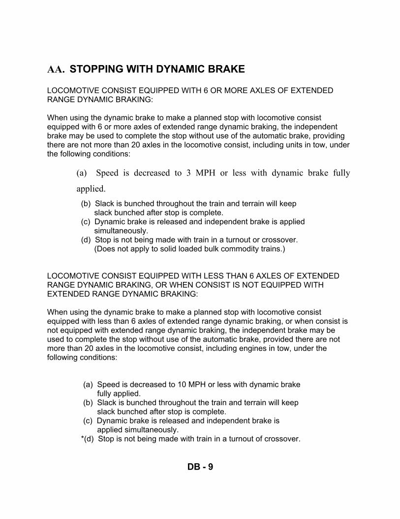
DB - 9
AA. STOPPING WITH DYNAMIC BRAKE LOCOMOTIVE CONSIST EQUIPPED WITH 6 OR MORE AXLES OF EXTENDED RANGE DYNAMIC BRAKING: When using the dynamic brake to make a planned stop with locomotive consist equipped with 6 or more axles of extended range dynamic braking, the independent brake may be used to complete the stop without use of the automatic brake, providing there are not more than 20 axles in the locomotive consist, including units in tow, under the following conditions:
(a) Speed is decreased to 3 MPH or less with dynamic brake fully
applied. (b) Slack is bunched throughout the train and terrain will keep
slack bunched after stop is complete. (c) Dynamic brake is released and independent brake is applied
simultaneously. (d) Stop is not being made with train in a turnout or crossover.
(Does not apply to solid loaded bulk commodity trains.) LOCOMOTIVE CONSIST EQUIPPED WITH LESS THAN 6 AXLES OF EXTENDED RANGE DYNAMIC BRAKING, OR WHEN CONSIST IS NOT EQUIPPED WITH EXTENDED RANGE DYNAMIC BRAKING: When using the dynamic brake to make a planned stop with locomotive consist equipped with less than 6 axles of extended range dynamic braking, or when consist is not equipped with extended range dynamic braking, the independent brake may be used to complete the stop without use of the automatic brake, provided there are not more than 20 axles in the locomotive consist, including engines in tow, under the following conditions: (a) Speed is decreased to 10 MPH or less with dynamic brake
fully applied. (b) Slack is bunched throughout the train and terrain will keep
slack bunched after stop is complete. (c) Dynamic brake is released and independent brake is
applied simultaneously. *(d) Stop is not being made with train in a turnout of crossover.

DB - 10
*(e) Train is not within the limits of a terminal except on main track.
*Does not apply to solid loaded bulk commodity trains.

DB - 11
The locomotive brake is not to be applied along with the dynamic brake: When speed is 3 MPH or less (extended range) and 10 MPH or less (non-extended range) and a stop is planned by use of the locomotive independent brake, the dynamic brake must be moved to the off position and independent brake applied immediately. (The dynamic brake handle left in the setup position gives an indication on the recorder tapes as having both applied at the same time.) Comparison of amperage for taper, high capacity taper, and flat systems of dynamic braking at speed of 40 MPH. (Except MAC series) HIGH CAPACITY THROTTLE POSITION TAPER TAPER FLAT 3 670 Amps 670 Amps 250 Amps 4 700 Amps 945 Amps 350 Amps 5 700 Amps 945 Amps 430 Amps 6 700 Amps 945 Amps 550 Amps 7 700 Amps 945 Amps 625 Amps 8 700 Amps 945 Amps 700 Amps

DB - 12
Dynamic Brake Retarding Force The effectiveness of the dynamic brake depends on the ability of the traction motors, while acting as generators, to convert some of the energy of the moving train into electrical energy and to dissipate the electricity through resistance grids as heat to the atmosphere. The dynamic brake resistance grids have a fixed, maximum horsepower capacity. Thus, the retarding force available from dynamic braking will vary with speed. Following is the amount of retarding force developed at different speeds with various types of dynamic brakes.

DB - 13
4 Axle Locomotives High Capacity Speed Standard Range Extended Range Extended Range 2 MPH 4,000 lbs. 15,000 lbs. 15,000 lbs. 6 MPH 10,000 lbs. 40,000 lbs. 37,000 lbs. 12 MPH 20,000 lbs. 40,000 lbs. 54,500 lbs. 18 MPH 30,000 lbs. 40,000 lbs. 54,500 lbs. 24 MPH 40,000 lbs. 40,000 lbs. 54,500 lbs. 30 MPH 30,000 lbs. 30,000 lbs. 40,500 lbs. 40 MPH 23,000 lbs. 23,000 lbs. 29,500 lbs. 50 MPH 20,000 lbs. 20,000 lbs. 22,000 lbs. 6 Axle Locomotives High Capacity Speed Standard Range Extended Range Extended Range 2 MPH 6,000 lbs. 15,000 lbs. 19,500 lbs. 6 MPH 15,000 lbs. 60,000 lbs. 50,000 lbs. 12 MPH 30,000 lbs. 60,000 lbs. 81,500 lbs. 18 MPH 45,000 lbs. 60,000 lbs. 81,500 lbs. 24 MPH 60,000 lbs. 60,000 lbs. 81,500 lbs. 30 MPH 47,000 lbs. 50,000 lbs. 72,000 lbs. 40 MPH 35,000 lbs. 35,000 lbs. 45,500 lbs. 50 MPH 30,000 lbs. 30,000 lbs. 34,000 lbs.
1. SD-80 MAC SERIES
Speed Maximum Braking Effort 0.5 MPH to 20 MPH Up to 96,000 lbs.

INTRODUCTION TO DYNAMIC BRAKES
Study Guide Questions
DB - 14
1. How does the dynamic brake retard the speed of a train? 2. How long must the throttle be in idle before going to braking (B) or set-up? 3. Why wait 10 seconds before going to dynamic brake? 4. Will movement of the throttle cause any increase or decrease in braking
current? 5. How long must the engineer wait before applying power after coming out of
dynamic brake?

INTRODUCTION TO DYNAMIC BRAKES
Study Guide Questions
DB - 15
6. When may the automatic and dynamic brakes be used together? 7. What restriction is placed on extended range dynamic braking when making
a planned stop if the automatic brake is being used in conjunction with the dynamic brake?
8. With standard dynamic brakes, what happens to dynamic braking effort at
speeds below 25 MPH? 9. How can current be maintained at a high level when voltage drops during
braking? 10. Why are speeds of 18, 12, and 6 MPH critical with extended range dynamic
brakes?

DB - 16
NOTES

DB - 17
NOTES

TRAIN HANDLING

TH - 19
OBJECTIVE The purpose of this lesson is to familiarize the locomotive engineer trainee with various concepts of train handling on Norfolk Southern. Each trainee will demonstrate knowledge of these concepts during train simulator sessions. This training will include, but is not limited to, starting, accelerating, cresting procedures, and negotiating different types of terrain. The locomotive engineer trainee will become familiar with and be able to apply appropriate rules and instructions found in NS-1, Rules for Equipment Operation and Handling. Trainees will also be required to pass a final train operations exam which will include questions pertaining to train handling methods and special instructions. In order to successfully complete phase I of their training, the trainee must score at least 80% on the Final Train Operations exam. INTRODUCTION Proper train handling requires careful consideration of train make-up, terrain, locomotive consist, and speed. Your goal as locomotive engineer should be to manage slack throughout the train to prevent damage to lading and equipment. You should always plan ahead. This may require you to regulate your train speed below the maximum authorized speed to properly control slack. In addition to planning ahead, good train handling involves anticipating unexpected events. How you respond to these events could be the difference between keeping the train intact, or a serious derailment. When thinking of train handling, words such as slowly, easy, minimal, and gradual are a good starting point.
2. LOCOMOTIVE AXLE LIMITS UNDER POWER When taking charge of a locomotive consist, the engineer must determine the total number of powered axles in the consist. NS-1 instructions limit the number of powered axles that can be used on the head-end of a train. Except on designated trains, no more than the equivalent of 24 axles may be operated under power on the head end of a train. High adhesion axles are equivalent to 1-1/3 conventional axles. Alternating Current (AC) traction motor-equipped axles are equivalent to 1-1/2 axles. Loaded grain trains not exceeding 100 cars are authorized to use four high adhesion six axle units (32 powered axles) on line.

TH - 20
When using the maximum number of powered axles, the throttle should be increased gradually to avoid the development of excessive tractive effort at low speed. Extreme care must be exercised while starting to prevent train separation and derailment. LOCOMOTIVE AXLE LIMITS IN DYNAMIC BRAKE In addition to determining the total number of powered axles in the locomotive consists, the engineer must ensure that the total number of dynamic braking axles does not exceed NS-1 instructions. Below are NS-1 instructions for equivalent dynamic braking axles on the head-end of a train. If a locomotive consist includes one or more units equipped with STANDARD dynamic brake, not more than the equivalent of 20 axles of dynamic braking may be used on the head end of a train. If ALL UNITS in the consist are equipped with EXTENDED RANGE dynamic braking, not more than the equivalent of 18 axles of dynamic braking may be used on the head end of a train. EXCEPTIONS:
x If all units in the consist are equipped with extended range dynamic brake, the equivalent of 20-axles may be used for trains handling solid bulk commodities such as coal, grain potash phosphate or similar bulk lading.
x The equivalent of 24-axles of dynamic braking may be used for designated trains
handling only loaded 100 ton cars equipped with high tensile (Grade E) knuckles and couplers.
x Except on designated trains, the dynamic brake must be cut out on all in access
of 18-axles.
3.
4.
5. STARTING A TRAIN How you start a train will depend largely on what type of grade the train is on. When starting on a level grade, the brakes should be fully released. Once the brakes are released, open the throttle one notch at a time, giving each throttle notch time to become effective. The locomotive will usually start moving in throttle position No. 1 or No. 2, depending on the whether the slack is bunched or stretched. Once the locomotive starts moving, keep just enough power applied to move the locomotive

TH - 21
slowly and evenly. Watch the ground and ammeter when starting. If the locomotive moves out too fast, reduce the throttle to take power away. Avoid high amperage. Once the slack is completely stretched, the train should normally require no more than No. 2 or No. 3 throttle position to begin moving.

TH - 22
Starting a train on an ascending grade requires a different approach. Power should be applied as the brakes release to stretch any slack that may be bunched. Starting a heavy train on an ascending grade may require throttle notch 4 to start the train moving and to avoid rolling backwards, however great care should be taken to avoid wheel slips which could break the train in two or cause rail burns. Careful attention is a must any time a throttle position above notch 3 is needed to start a train. Things you should consider if experiencing difficulty while starting;
x Brakes fully released x Adequate locomotive power for train tonnage x Types of locomotives x Train location, i.e. heavy grade, turnout or crossover or curve, (danger of
stringlining) x If after an emergency brake application, are cars derailed?
Note: When starting, continued application of power when locomotive(s) is not moving can result in damage to the traction motors from burns on the commutators.
Starting a train on a descending grade requires yet another approach. In this situation, use of the independent brake is acceptable. When starting a train on a descending grade locomotive brake cylinder pressure should be reduced gradually to prevent the head end from stretching too quickly. Enough brake cylinder pressure should be maintained to prevent a heavy run out while allowing the weight of the locomotive(s) to begin stretching the train. Continue reducing the brake cylinder pressure until all slack is stretched and the entire train is moving down the grade at which time the independent brake should be fully released.
BB. STARTING A TRAIN WITH AC TRACTION When starting a train with AC traction locomotives (SD 80MAC) on level or descending grade, use the same procedure as with DC traction locomotives, however starting on ascending grades will be somewhat different. AC traction allows the throttle to be advanced to start the train with the brakes applied because AC traction motors do not have commutators and brushes, therefore they are not susceptible to damage from high current levels while the locomotive is not moving. When starting a train on an ascending grade you must apply sufficient tractive effort to move the train before you release the independent brake. If you fail to do

TH - 23
this and the train rolls backwards, the locomotive will go into full dynamic braking at 2.5 MPH and you will have to stop and begin the starting procedure again.

TH - 24
Another important feature of AC traction is its’ tremendous starting capabilities because of computer controlled wheel slip. Until you become familiar with these locomotives you may be tempted to reduce power when starting under extreme starting conditions because the locomotive may shake and vibrate as the computer adjust current levels to the traction motors. This is normal because of the advanced wheel slip system; the throttle should not be reduced unless you receive a continuous wheel slip light. Use the same procedure to accelerate as with DC traction locomotives. For any type of locomotive (AC or DC traction motors), after the entire train is moving, allow the train time to adjust. Amperage will level off and begin to decrease as the train accelerates. Use sand only when necessary. ACCELERATING THE TRAIN After the train is moving, it can be accelerated. This is accomplished by advancing the throttle, observing the speed indicator, the rate of acceleration and the ammeter. The ammeter will level off and begin to drop as the train accelerates. When this happens, advance the throttle one notch. This increases the current to the traction motors. The ammeter will start to rise and speed will increase. As speed increases, the ammeter again will level off and start falling. When this happens, the throttle can be advanced another notch. This procedure can be repeated until the desired speed is reached. Do not force the throttle (advance it too quickly) as this could result in wheel slip, and broken knuckles or couplers.
1. THROTTLE MODULATION Most locomotives used in freight service are equipped with dynamic brakes. However, there may be times when you will have to operate a train without the benefit of dynamic brakes. In some situations, the throttle can be used to control train speed. On level grade when the train reaches the desired speed, the throttle can be reduced to provide just enough power to maintain that speed. When operating in undulating (rip-rap) terrain, your goal is to keep the locomotive(s) and the rear of the train moving as close to the same speed as possible which will keep slack forces to a minimum. When the locomotive(s) start up hill, they will tend to slow down; when this happens, advance the throttle to keep the speed constant. When the locomotives start downgrade, reduce the throttle to keep the head end from accelerating too quickly.

TH - 25

TH - 26
Give the train time to adjust to power changes. Reducing the throttle too quickly can result in unnecessary slack action. Allow the part of the train going upgrade to keep the speed constant or slightly reduce the speed. Open the throttle, as needed, to hold the train speed constant. Allow each notch to become effective before adding another throttle notch.
2. CONTROLLING SLACK Several factors are involved in controlling slack in a train. Depending on the location different techniques are required. Here, we will discuss a few general train-handling techniques. As the engineer you must know the length of your train. NS-1 Rule A-29 states “an electronic record with total weight and length of train will be maintained on the controlling locomotive.” One way to determine train length if not provided is by using a wayside detector. To do this start the distance counter when the locomotive passes a detector. Stop the counter when the detector sounds off. Wayside detectors generally sound 20 car lengths after the rear car passes the detector. Deducting 20 car lengths from the distance counter reading will give an approximate length of train. Slack at the rear of train will run in or out near the same location regardless of the length of the train. Slack cannot be out run, but can be cushioned. The faster the speed the harder the run-in or run-out. Slack usually works out of a train when the rear is starting up grade. If possible, operate your train so you can advance the throttle just before the slack comes in, or slightly reduce dynamic braking amperage if braking. This will cushion the slack. A good rule of thumb to follow: If the locomotive is in a position to increase speed when the slack is to be stretched, notch off on the throttle or increase the dynamic brake. If the locomotive is on an ascending grade when the slack is about to stretch out, they will be decreasing speed, and no action is necessary. Any portion of the railroad where slack action is a problem can usually be handled by slowing down. DRIFTING A TRAIN
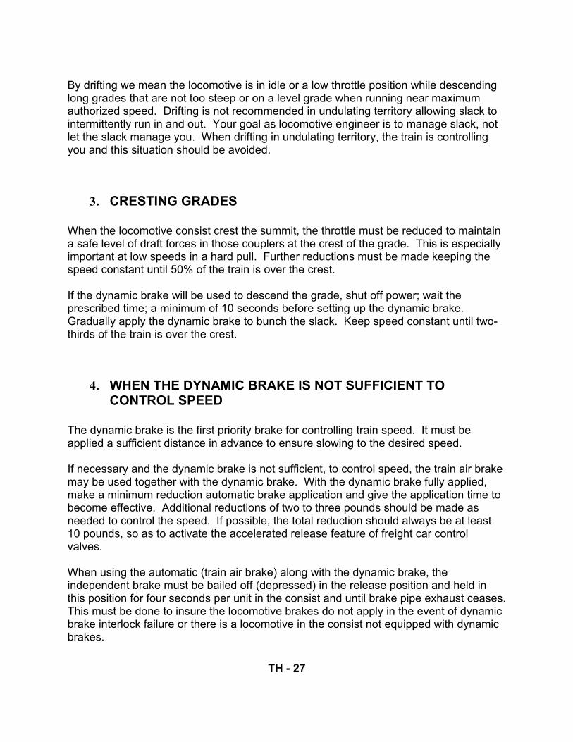
TH - 27
By drifting we mean the locomotive is in idle or a low throttle position while descending long grades that are not too steep or on a level grade when running near maximum authorized speed. Drifting is not recommended in undulating territory allowing slack to intermittently run in and out. Your goal as locomotive engineer is to manage slack, not let the slack manage you. When drifting in undulating territory, the train is controlling you and this situation should be avoided.
3. CRESTING GRADES When the locomotive consist crest the summit, the throttle must be reduced to maintain a safe level of draft forces in those couplers at the crest of the grade. This is especially important at low speeds in a hard pull. Further reductions must be made keeping the speed constant until 50% of the train is over the crest. If the dynamic brake will be used to descend the grade, shut off power; wait the prescribed time; a minimum of 10 seconds before setting up the dynamic brake. Gradually apply the dynamic brake to bunch the slack. Keep speed constant until two-thirds of the train is over the crest.
4. WHEN THE DYNAMIC BRAKE IS NOT SUFFICIENT TO CONTROL SPEED
The dynamic brake is the first priority brake for controlling train speed. It must be applied a sufficient distance in advance to ensure slowing to the desired speed. If necessary and the dynamic brake is not sufficient, to control speed, the train air brake may be used together with the dynamic brake. With the dynamic brake fully applied, make a minimum reduction automatic brake application and give the application time to become effective. Additional reductions of two to three pounds should be made as needed to control the speed. If possible, the total reduction should always be at least 10 pounds, so as to activate the accelerated release feature of freight car control valves. When using the automatic (train air brake) along with the dynamic brake, the independent brake must be bailed off (depressed) in the release position and held in this position for four seconds per unit in the consist and until brake pipe exhaust ceases. This must be done to insure the locomotive brakes do not apply in the event of dynamic brake interlock failure or there is a locomotive in the consist not equipped with dynamic brakes.

TH - 28
5. WHEN MAKING A RUNNING RELEASE OF THE TRAIN AIR BRAKES, THE DYNAMIC BRAKE MUST BE KEPT FULLY APPLIED (MAXIMUM AMPERAGE) UNTIL THE AIR BRAKES HAVE RELEASED THROUGHOUT THE TRAIN.

TH - 29
6. RELEASING DYNAMIC BRAKE The dynamic brake must not be released in undulating (rip-rap) terrain. An example of this would be part of the train going uphill and the locomotive going downhill. This would cause a severe run out, possibly causing a train separation. The dynamic brake must not be released when the train is descending a heavy grade. Pick a spot at the bottom of the grade or where the locomotive has started upgrade.
7. THE DYNAMIC BRAKE MAY BE RELEASED WHEN THE TRAIN IS ON LEVEL GRADE. AGAIN, THE ENGINEER SHOULD PICK A PLACE WHERE THE TRACK TURNS UPGRADE OR IN A CURVE WHERE THE LOCOMOTIVE IS IN A BIND TO PREVENT THE HEAD-END FROM RUNNING OUT. TRAIN SPEED, TERRAIN, AND SLACK CONDITION WILL DETERMINE HOW MUCH POWER IS APPLIED AFTER RELEASING THE DYNAMIC BRAKE.
8. EMERGENCY_BRAKE_APPLICATION 4/1/2004
When the speed of train cannot be controlled properly from the use of the dynamic and/or service brake application, an emergency brake application must be initiated without hesitation. Note: Any train descending a grade of 1 percent or greater over a distance of 3 continuous miles must be immediately brought to a stop by an emergency brake application, if necessary, when the movement exceeds the maximum authorized speed at that location by more than 5 MPH. If an emergency brake application is initiated from the automatic brake valve or emergency brake valve in the locomotive cab, THE TWO-WAY EOTD, IF SO EQUIPPED, WILL BE ACTIVATED TO INITIATE AN EMERGENCY BRAKE APPLICATION FROM THE REAR. The automatic brake valve handle must be left in the emergency position until after the train has stopped. OTHER EMERGENCY BRAKE APPLICATIONS If an emergency brake application is initiated from the rear of the train (i.e., pusher service, caboose), when communication is available, the engineer on the controlling locomotive must immediately place the automatic brake valve in the emergency position.

TH - 30
If the PC switch activates following an undesired emergency application, the automatic brake valve must be placed in the emergency position and left there until the train stops.

TH - 31
9. EMERGENCY BRAKE APPLICATION WHILE TRAIN IS IN POWER
If an emergency brake application occurs while in power and slack is stretched, the independent brake must be bailed off immediately in the release position to prevent undesired slack run-in and possible jackknifing of the train. As the emergency application begins to slow the train, the throttle must be dropped at a rate that will allow the train to remain stretched but will not cause excessive stress on knuckles or draw-heads. The throttle will continue to be reduced until the PC switch is activated, about 20 seconds, at which time engine speed will drop to idle and amperage will drop to zero. When an emergency application is initiated from the automatic brake valve (desired), the PC switch activates immediately. The independent brake must be bailed off until the train has come to a complete stop. An independent brake application on top of an emergency application would cause the brake cylinder pressure to build up higher on some units (90 pounds or more) which could cause the wheels to lock and slide. Once the train stops, fully apply the independent EMERGENCY BRAKE APPLICATIONS WHILE IN DYNAMIC BRAKE OR WHEN SLACK IS BUNCHED When an emergency brake application, either desired or undesired, occurs while in dynamic brake, or slack is bunched, Norfolk Southern locomotives will continue to load even after the PC switch activates. This allows for dynamic braking effort throughout the stop. When the train slows to point where the dynamic brakes are no longer effective, the independent brake should be applied to a level that will prevent a run out while continuing to bail off in the release position. This will occur at different speeds depending on the type of dynamic brakes. Note: A running release must not be made after an emergency brake application.

TH - 32
10. AIR BRAKE USE ON HEAVY DESCENDING GRADES WHEN TRAIN HAS STOPPED AND TRAIN AIR BRAKES WILL BE REQUIRED TO SAFELY CONTROL THE MOVEMENT
When a train has been stopped by either an emergency brake application or brake pipe reduction of 25 PSI or more and another brake application will be required as grade is descended; the following steps must be followed to ensure proper charging of train line system. 1. Apply sufficient hand brakes to secure train. 2. Release air brakes 3. Charge air brake system to within 15 PSI of feed valve setting and then wait ten
minutes before proceeding. 4. Handbrakes may remain applied until the train safely descends the grade.
Note: Existing rules governing inspection of trains after an emergency brake application will apply.
When a train has stopped to remove pusher locomotives, 1. Drape and hold the train with the independent brake if possible. 2. Keep the brake system fully charged. 3. If the train is not draped and held or the brake system is not kept fully charged,
remove the pusher locomotives at the bottom of the grade. NOTE: Do not remove the pusher locomotives on a grade unless the brake system remains fully charged.

TH - 33
11. BRAKING AGAINST POWER The dynamic brake is the first priority for controlling train speed. On trains where we do not have dynamic brakes and we cannot control the train speed by throttle modulations or drifting, we will use the train air brakes. When “stretch braking,” you should start far enough in advance so light reductions can be made to control speed. Start braking by making a minimum reduction with the automatic brake valve. This reduction will result in a six to eight pound drop in brake pipe pressure and about ten pounds of brake cylinder pressure through the train. When brakes become effective in the train, reduce the throttle gradually to keep the train stretched, keeping stress on couplers at a safe level. Additional reductions of two to three pounds may be made as needed, reducing the throttle accordingly. Watch the ammeter. Allowing amperage to increase slightly while braking against power will keep slack stretched, but high amperage can result in a train separation. If possible, the total reduction should always be at least ten pounds to activate the accelerated release feature of freight car control valves. If making a running release, gradually reduce the throttle after placing the automatic brake handle in the release position to reduce stress on knuckles and couplers. When a train’s brakes are re-applied after a running release and before the brake system is fully recharged, the brake pipe reduction must be at least 5 PSI GREATER than that used for the last brake application to ensure that the brakes reapply. EXCEPTION: When using 100% retainers. STOPPING WHEN DYNAMIC BRAKES ARE NOT AVAILABLE To stop when dynamic brake is not available use the same procedure as for slowing making additional reductions of two to three pounds to complete the stop. Just prior to stopping, reduce the throttle to idle. Keep the independent brake depressed (bail-off) for four seconds per unit and as long as brake pipe is exhausting. If train brakes should apply in emergency while braking against power, and train is stretched, the independent brake must be kept bailed off (until stopped) to keep train

TH - 34
stretched. Allowing the locomotive brake to apply under these conditions could cause the train to jackknife.

TH - 35
STOPPING ON AN ASCENDING GRADE Air brakes can and should be used if needed to properly control speed or stop a train; however anytime the automatic brake is applied there’s always a chance an emergency brake application may occur. If stopping on an ascending grade and planning far enough in advance, you may be able to stop by reducing the throttle, and allowing the train to stall on the grade. You should apply the automatic brake just as you complete the stop to prevent rolling backwards and to comply with NS-1 Rule A-31 ensuring train-line continuity.
12. USE OF INDEPENDENT BRAKE AND AUTOMATIC BRAKE The locomotive brake may be allowed to apply to a safe level from an automatic brake application when there are more locomotives than cars in the train or in a very short train when slowing or stopping. The independent brake is to be bailed off during automatic brake applications on all other trains. For instance, there may be times when locomotive brakes are needed for proper train handling; for instance, more locomotive units than cars, more weight in the locomotive than in the train. Under these conditions, we may allow the locomotive brakes to apply along with the train air brakes. The normal situation would be to keep the locomotive brake bailed off with the independent while making train air brake applications.
13. RUNNING RELEASE OF TRAIN AIR BRAKES Never release the brakes while the automatic brake valve is exhausting. This means the application is not complete throughout the train and could cause sticking brakes. This applies to all trains. After the automatic brake is placed in the release position, reduce the throttle further to lower the stress on the couplers while the brakes are releasing. The train air brakes apply serially from the front of a train to the rear and release in the same manner. To keep the same power applied with the brakes releasing on the head end, while brakes are still applied on the rear could result in pulling the train in two. When reapplying power, always make sure the brakes are released before advancing the throttle. This can be done by monitoring the flow meter on locomotive units so equipped. A running release must not be made with any slack bunched unless maximum dynamic brake amperage is in use.

TH - 36
A running release must not be made after an emergency brake application, desired or undesired. The automatic brake must be placed in the emergency position as soon as the PC switch activates and left there until the train stops except on radio trains the handle of the automatic brake will be left pinned in the release position. THE FOLLOWING INSTRUCTIONS AND THE 15 PSI OR LESS REDUCTION DO NOT APPLY WHEN CRESTING OR DESCENDING HEAVY GRADES, TO DISTRIBUTED POWER TRAINS, OR TO TRAINS WITH 74 CARS (3,700 feet) OR LESS
Note: A heavy descending grade is defined as a descending grade of 1% or more. If in doubt about the grade and braking requirements, consult the Division Road Foreman of Engines.
14. TRAINS OVER 125 CARS OR 6,250 FEET Any time the train air brake is applied on a train of more than 125 cars, (Over 6,250 feet) the train must be brought to a stop before releasing the train air brakes.
15. 101 CARS TO 125 CARS WITH DYNAMIC BRAKES 5,050-6,250 FEET
The air brakes may be released on trains with 101 cars to 125 cars (5,050 – 6,250 feet) without stopping, if dynamic brakes are being used, the brake pipe reduction does not exceed 15 pounds, and the speed is 35 MPH or more at the time of the release.
16. 101 CARS TO 125 CARS WITHOUT DYNAMIC BRAKES 5,050-6,250 FEET
When the train air brake is applied on a train with 101 cars to 125 cars (5,050 – 6,250 feet) and dynamic brakes are not in use, the train will be brought to a stop before releasing the brakes.
17. 75 TO 100 CARS

TH - 37
A running release may be made on trains with 75 cars to 100 cars (3,750 – 5,000 feet), if the brake pipe reduction does not exceed 15 pounds and the speed is 30 MPH or more at the time of release.

TH - 38
PROPER USE OF INDEPENDENT BRAKE The independent brake may be used for the following reasons:
1. Any form of switching service, whether brake pipe air is coupled or not. 2. When operating "light engines". 3. Starting trains on descending grades or, 4. In an emergency
18.
19.
20. USE OF INDEPENDENT AND DYNAMIC BRAKE Under no circumstances will the independent (engine brake) and the dynamic brake be used together. Remember, when using the automatic brake with dynamic brake, bail off the independent brake frequently in the release position to insure the locomotive brakes do not apply. Any locomotive brake cylinder pressure developed while in dynamic brake could cause sliding wheels. LOCOMOTIVE CONSIST EQUIPPED WITH 6 OR MORE AXLES OF EXTENDED RANGE DYNAMIC BRAKING: When using the dynamic brake to make a planned stop with locomotive consist equipped with 6 or more axles or extended range dynamic braking, the independent brake may be used to complete the stop without use of the automatic brake, providing there are no more than 20 axles in the locomotive consist, including units in tow, under the following conditions:
(a) Speed is decreased to 3 MPH or less with dynamic brake fully applied. (b) Slack is bunched throughout the train and terrain will keep slack bunched
after stop is completed. (c) Dynamic brake is released and independent brake is applied
simultaneously. *(d) Stop is not being made with train in a turnout or crossover.
*Does not apply to solid loaded bulk commodity trains.

TH - 39
LOCOMOTIVE CONSIST EQUIPPED WITH LESS THAN 6 AXLES OF EXTENDED RANGE DYNAMIC BRAKING, OR WHEN CONSIST IS NOT EQUIPPED WITH EXTENDED RANGE DYNAMIC BRAKING: When using the dynamic brake to make a planned stop with locomotive consist equipped with less than 6 axles of extended range dynamic braking, or when consist is not equipped with extended range dynamic braking, the independent brake may be used to complete the stop without use of the automatic brake, provided there are not more than 20 axles in the locomotive consist, including units in tow, under the following conditions:
(a) Speed is decreased to 10 MPH or less with dynamic brake fully applied. (b) Slack is bunched throughout the train and terrain will keep slack bunched
after stop is completed. (c) Dynamic brake is released and independent brake is applied
simultaneously. *(d) Stop is not being made with train in a turnout or crossover. *(e) Train is not within the limits of a terminal except on main track.
*Does not apply to solid loaded bulk commodity trains. BACK UP MOVEMENTS Prior to back-up movement, consideration must be given to tonnage, train length, position of heavy and light cars, grade conditions, track curvature, turnouts, types of units, and number of units in the consist.
1. Train air brakes are to be fully released before applying maximum power.
2. Amperage should be limited to a safe level throughout the movement.
3. No more than the equivalent of 16 powered axles (as referenced in the NS Locomotive series table) may be used to make a back-up movement where train and track conditions indicate a high risk for jackknifing rail turnover, or pushing cars off the outside of sharp curves.
4. Back-up movements must not be made account inability to start a forward
movement.
21.
22.

TH - 40
23. SHOVING AGAINST THE BRAKES In some situations it may be necessary to shove a cut with the train brake applied. Apply power gradually. Watch ammeter. Too much pressure against the cut can cause a derailment. When the cut starts moving, make a minimum reduction with automatic brake keeping the locomotive brake bailed off. Use only enough power to maintain speed. Watch for any sudden surge in amperage which could indicate a derailment. As the brakes become effective the amperage will start to rise. Keep a careful watch on amperage as to much can derail the cars. If excessive amperage is needed to keep the cut moving, allow the movement to stop, release the brakes, and begin the move over again re-applying the brakes if necessary.
24. BACKING UP WHEN CUT IS TO BE CONTROLLED WITH INDEPENDENT BRAKE
Applying brakes too heavily when shoving will result in a hard run-out and possibly a broken knuckle or coupler. When cut starts moving, apply locomotive brakes very lightly with independent brake and allow slack to stretch. Keep locomotive brakes applied to control speed of the cut. Keep cut stretched until stopped. If automatic brake is needed to complete the stop, apply it along with independent brake while bailing off excess pressure.
25. SWITCHING The engineer is responsible for proper handling or stopping the train. Always move at a speed that will allow you to stop in the proper distance. If the cut is being handled without air, move so the stop can be made with the locomotive brake. Judge your distance. When you are to move a certain distance such as ten car lengths, pick out objects on the ground so you can see how far you have traveled and how far you have to go before you stop..

TH - 41
If switching on a grade, know you have sufficient stopping power before moving. If the grade is too steep to control a cut with the locomotive brake, have the air coupled and allow ample time to charge before moving.
26.
27.
28. OPERATING LOCOMOTIVES OVER RAILROAD CROSSINGS (DIAMONDS)
When the locomotive is being operated at a speed greater than 25 MPH in power or dynamic brake, mechanical shock (flash over), which can damage traction motors and trip the ground relay may occur at railroad crossings. To avoid this, reduce the throttle to notch 4 or lower at least eight seconds before reaching the crossing. This must be handled to create as little slack action as possible. Plan your move in advance.
29.
30. PUSHER SERVICE OR SHOVING TRAINS Too much pressure applied when shoving a train could result in jackknifing the train. On some locomotives, there is a delay in dropping out the PC switch in case of an emergency brake application even though the brake handle is in handle-off position. This could result in the shoving locomotive remaining in power and shoving through the train. The shoving locomotive does not furnish any brake pipe pressure. Brake pipe pressure is controlled by the lead locomotive. This is necessary to insure instant power knockout in case of an emergency application from any source. This gives the engineer on the lead locomotive unit complete control of the train brakes. L-248. The following procedures must be observed when pusher service is required:
a) Couple engines to rear of train or cut of cars to be pushed. Place automatic brake valve in "HANDLE OFF" position. This is necessary to provide "POWER

TH - 42
CUT-OFF" (PC) feature when a brake pipe initiated emergency occurs. Cut brake pipe cutout cock out on pusher engines, allowing train line air to be controlled by the lead engine.
b) Couple train line hoses and open both angle cocks. c) When helper locomotives are coupled to the rear of a train, a visual inspection
must be made to determine that the helper locomotives brakes respond properly from a 20 PSI reduction on the controlling locomotive.
d) When more than one unit is pushing, the locomotive coupled to rear of train must be unoccupied.
e) If a caboose is ahead of the pusher locomotives, the caboose must be unoccupied while pushing.

TH - 43
f) When pusher service is no longer required, the movement must stop before pusher units are uncoupled, except when automatic uncoupling device is authorized.
g) Close both angle cocks, except where automatic uncoupling device is authorized. h) Cut in double-heading cock on the pusher engines, test independent brake and
separate from train or cut of cars being pushed. i) No more than the equivalent of 16 conventional powered axles may be used in
pusher service. (Exception: The equivalent of 24 conventional powered axles may be used in pusher service where authorized by special instructions and train being pushed is solid loaded bulk commodity train.) High adhesion axles are equivalent to one and one-third conventional axles. Alternating current (AC) traction motor-equipped axles are equivalent to 1-1/2 axles.
TESTING POWER KNOCKDOWN FEATURE A locomotive must not be used as the controlling unit in a pusher consist unless it is known to be equipped with a 'power knockdown' feature that reduces power or engine speed without delay following an emergency application of the air brakes initiated from any source other than the automatic brake valve. The following test will be used to determine that the unit is equipped with an operative 'power knockdown' feature:
x Reverser must be centered;
x Generator field switch must be in OPEN position;
x Automatic brake valve handle must be in HANDLE OFF position and brake pipe cutout cock must be in OUT position;
x Throttle must be advanced to No. 3 position;
x Emergency valve must be opened to determine that 'PC' switch activates and engine speed is reduced to idle.
HELPER SERVICE L-249. In double-heading service, the engineer of the leading locomotive shall operate the brakes. ("Double-heading" means the use of more than one locomotive on the head end, when one of the locomotives is not equipped for MU operation.) On all other locomotives in the train, the brake pipe cutout cock to the brake valve must be cut out, the maximum main reservoir pressure maintained and brake valve handles kept in HANDLE OFF position. In case it becomes necessary for the leading locomotive to give

TH - 44
up control of the train short of its destination, a test of the air brakes must be made to see that the brakes are operative from the automatic brake valve of the locomotive taking control of the train. When two locomotive consists are coupled, they must be set up for MU operation when possible. L-250. In case of emergency condition, the engineer of the second or pusher locomotive will stop the train by applying the brakes in emergency. The engineers must have a complete understanding before proceeding.
REDUCING TONNAGE WHEN OPERATING LOCOMOTIVE WITH TRACTION MOTOR CUT OUT
When traction motors on a locomotive unit are cut out for any reason, tonnage for that unit may be reduced. This applies when the ruling grade is ahead of you. Use good judgment in setting out tonnage. Note: When cutting out traction motors, the Chief Dispatcher must be notified.
31. SHORT TIME RATING OF LOCOMOTIVE UNITS Short time ratings are posted at the engineer's stand or on the ammeter gauge and must not be violated. If train cannot be moved over a grade without exceeding the short time rating on any unit, either double the hill or get help from a pusher. Do not exceed the short time rating. On units so equipped, observe short time operation plate instructions or load meter which has been graduated to show the time in minutes that various loads may be carried. Operation for the lowest short time rating of any unit in the consist will govern the maximum load to be carried. The maximum continuous current rating and the short time operating limits were developed for throttle notch 8 operation. These values must be decreased at lower throttle positions because engine speed and, consequently, traction motor cooling air is reduced. If short time ratings are exceeded, movement must be stopped, reverser centered, and throttle advanced to the maximum position (No. 8) for at least 10 minutes to cool traction motors.

TH - 45
Newer, locomotives will automatically reduce the current to the traction motors to prevent overheating.

TRAIN HANDLING Study Guide Questions
TH - 46
1. Describe how you would start a train moving on level grade. 2. At what throttle notch will the train normally start to move? 3. After the train is started, describe how you would accelerate the train. 4. What happens in train handling if the throttle is shut off too quickly?

TRAIN HANDLING Study Guide Questions
TH - 47
5. Describe how you would complete a stop using the independent brake with 6 or more axles of extended range dynamic brakes in the locomotive consist.
6. Describe what you would do if while shoving against the brakes, you experienced
excessive amperage? 7. Under what conditions are the dynamic brake and the automatic air brake used
together? 8. Under what condition are the dynamic brake and the independent brake used
together?

TRAIN HANDLING Study Guide Questions
TH - 48
9. If all locomotives in the consist are equipped with extended range dynamic brake, except on designated or solid loaded bulk commodity trains, how many equivalent dynamic braking axles are allowed on the head-end of a train?
10. What should be considered if you experience difficulty in starting a train? 11. When braking against power, what action do you take when the amperage
increases and the train starts to decrease speed? 12. When making a backup movement against the air brakes, what could happen if
you put too much pressure against the cut?

TRAIN HANDLING Study Guide Questions
TH - 49
13. If operating a mixed freight train with 110 cars on level grade can you make a running release of the air brakes without stopping?
14. While dynamic braking, it was necessary to apply the automatic brake to control
your speed. In order to make a running release of the air brakes, what must you do with the dynamic brake?
15. What action would you take when switching if the cut can not be handled safely
with the independent brake? 16. When cresting the summit of a steep grade, what should you do with the throttle
and why? 17. When using the train air brake, what must you do with the independent brake?

TRAIN HANDLING Study Guide Questions
TH - 50
18. When making an automatic brake application, what should the initial reduction be? How much should the total reduction be?
19. When would it be permissible to use the independent brake in starting a train? 20. When the locomotive brakes are needed for proper train handling, how do we
allow them to apply? 21. During an undesired emergency application, how would you handle the
locomotive brakes?
In Power
In Dynamic Brake

TRAIN HANDLING Study Guide Questions
TH - 51
22. How would you operate a locomotive over a railroad crossing at grade if in excess of 25 MPH?
23. What precautions would you take before shoving a train as a helper locomotive? 24. What is a "heavy grade"? 25. When operating a train and not using dynamic brakes, what is the greatest
number of cars you are allowed to make a running release with on a level grade?

TH - 52
CC. NOTES
DD.

TH - 1
EE. TROUBLESHOOTING A DIESEL LOCOMOTIVE

TS - 2
1. OBJECTIVE The objective of this lesson is to acquaint a trainee with potential malfunctions on a locomotive which will be within the scope of his/her responsibility when he/she becomes an Engineer. As a result of discussions of potential symptoms and corrective procedures, at the conclusion of this lesson the trainee will be familiar with the common malfunctions which can occur on a locomotive unit on the line of road and will be conversant with the most common troubles and the recommended corrective actions. The trainee will have completed a troubleshooting chart, which he/she will be able to use as a reference following the training. The trainee will complete an examination, which will sample his/her understanding of locomotive malfunctions, with a score of at least 80%. In any machinery, whether moving or stationary, there are malfunctions which can occur. Locomotives are no exception. When malfunctions do occur on the line of road, there are some things an Engineer can do to correct the problem. In this lesson we will discuss these problems and what you can do to overcome them. The chart you have covers the topics we will discuss during this lesson. We will fill it out as we discuss each topic.

TS - 3
PROTECTION DEVICES FOR THE DIESEL ENGINE ENGINE OVERSPEED TRIP (RPM) This device protects the engine from overspeeding by shutting it down.
2. LOCATION AND DESCRIPTION On EMD locomotive units with a governor, the overspeed trip is located on the governor end of the diesel engine. It is a lever about 10 inches long. During normal operation the reset lever is positioned at eleven o'clock. When tripped, it will be at one o'clock. Note: EMD SD70 and MAC-80 type locomotives with EMDEC system incorporates a diesel engine overspeed function that eliminates the need for the traditional mechanical overspeed device. The EMDEC overspeed function reduces the amount of fuel going to the engine, but does not shut it down. EMDEC returns fuel injection to normal levels when engine speed has dropped to normal. On older General Electric locomotive units the overspeed trip is located under the engine governor. It will be a reset button and when tripped will protrude only 1/8". On C-39-8 locomotive units, a lay shaft located at governor end, which may be used in starting by pushing, will also set overspeed trip by pulling lay shaft handle out to full travel and holding for three seconds. On the DASH 9 and some DASH 8’s the overspeed is reset through the DID panel.
3. REASON FOR TRIPPING The engine overspeed trips any time the diesel engine reaches a dangerous speed, (RPM), usually about 10 to 15 percent above the full load speed. Some of the things that make it trip are: the electrical load on the alternator on any unit is suddenly dropped, stuck fuel injectors, and during transition changes.

TS - 4

TS - 5
Diesel Engine Shuts Down When the Overspeed Trips When the overspeed trips, the diesel engine will shut down, except on SD-70s and MAC-80s. The alarm received will be a bell ringing on each unit in the consist and a no power light on the unit with the overspeed tripped. On EMD turbo-charged locomotive units, you will also receive a white turbo lube pump light.
4. TO RESTART THE ENGINE To restart the engine on EMD units, place the isolation switch in the isolate position; this eliminates the no power light and bell. Reset the overspeed trip by moving the lever counter clockwise to the eleven o'clock position until it latches. Then restart the engine in the conventional manner. The turbo lube pump light will remain on until it times out. To restart the engine on GE units, place the engine control switch (this is equivalent to the isolation switch on EMD units) to the start position. This eliminates the bell and no power light. Reset the overspeed trip by shoving in on the reset button, pulling on the lay shaft and hold for three seconds, or resetting the DID panel on some Dash 8 and all Dash 9 locomotives. Then restart the engine in the conventional manner. Note: If either type engine continues to trip the overspeed protection device, limit operation of the locomotive to the 7th notch.
5. ENGINE CANNOT BE STARTED WITH THE OVERSPEED TRIPPED
An EMD unit cannot be started with the overspeed tripped. The overspeed trip acts to position the injectors in a no-fuel position. The engine could be rotated but would never start with the overspeed tripped. A GE unit will start while holding in the lay shaft but will die when the lay shaft is released.

TS - 6
LOW OIL SHUTDOWN DEVICE This device shuts the engine down in case of low lube oil pressure, high lube oil suction pressure, and by other safety features tripping.
6. LOCATION AND DESCRIPTION On EMD units the low oil device is a small plunger on the front of the governor. When tripped, a red ring will show on the plunger. On SD70 and MAC-80 units the EMDEC panel has a red indicator light that will light when lube oil pressure has become dangerously low. After checking lube oil level the EMDEC panel must be reset. On GE Dash-7 locomotive units, this governor shutdown relay with reset button is located in the electrical cabinet in the room adjacent to the crew cab. On C-39-8 locomotive units, the low oil relay will reset automatically. On GE Dash 8 and Dash 9 locomotive units they can be reset from the DID panel on the engine control panel in the cab.
7. REASON FOR TRIPPING This device trips any time the lube oil pressure becomes low due to low lube oil, lube oil diluted with fuel oil or water, hot lube oil, or clogged lube oil filters.

TS - 7
Engine Shuts Down When the Low Oil Device Trips
Whether on EMD or GE locomotive units, when the low oil device trips, the diesel engine shuts down. The alarm bell will ring on each unit in the consist, and the no power and governor shutdown lights will light on the unit where the low oil device tripped. On EMD locomotive units with turbochargers, you will also receive a turbo pump light.
8. TO RESTART THE ENGINE It is important to remember that anytime a low lube oil device trips on an engine, you must check oil level in crankcase before attempting to restart the unit. To restart an EMD locomotive, place the isolation switch in the isolate position. This turns off the no power light and bell. The governor shutdown light will burn until you shove in on the reset button on the front of the governor. Other devices that may be required to reset would be the low water button or the crankcase over-pressure button located below the manual lay shaft lever. Then restart the engine in the conventional manner. The turbo lube pump light will burn until it times out. To restart the engine on GE locomotive units, place the engine control switch in the start position. This eliminates the no power light and bell. The governor shutdown light will continue to burn until the low oil shutdown device is reset. On Dash-7 type locomotives you will have to press the governor shutdown reset tab located in the electrical cabinet. This cabinet is adjacent to the crew cab. On C-39-8 locomotive units, the low oil relay will reset automatically. On GE Dash 8 and Dash 9 locomotive units they can be reset from the DID panel on the engine control panel.
9. ENGINES CANNOT BE STARTED WITH LOW OIL DEVICE TRIPPED
Whether an EMD or GE locomotive unit, the engine cannot be started with the low oil device tripped. On locomotive units that have the start switch located in the engine room, the engine could be started by pushing in on the lay shaft but would immediately shut down again when the lay shaft is released.

TS - 8
LOW WATER DEVICE
Shuts the engine down when the cooling water falls below a safe level.
10. LOCATION AND DESCRIPTION
On EMD locomotive units the low water device is located on the governor end of engine just to the right and below the governor, in the EPR (Engine Protector Relay). There is a reset button that protrudes and displays a red ring when tripped. The reset button could be either the top or bottom button in this housing. Some GE units have a Governor Holding Relays in the high voltage cabinet or can be reset by the computer. On GE Dash-7 units the reset for low water is located in the electrical cabinet adjacent to the crew cab. You must depress reset tab on the relay marked “hot engine” (due to low water level). This relay may be labeled “LWP” for low water pressure. On GE Dash 8 and 9 locomotive units they can be reset from the DID panel on the engine control panel in the cab.
11. ENGINE SHUTS DOWN WHEN THE LOW WATER DEVICE TRIPS
On EMD locomotive units when the cooling water becomes dangerously low, the low water device trips. The button is on the EPR relay and is labeled low water. When tripped it protrudes and shows a red ring. This causes the low oil switch on the governor to trip, causing the engine to shut down. The alarm received is a bell on each unit of the consist, a blue light, and a yellow governor shutdown light on the unit affected. On EMD locomotive units that are turbo charged, you will also receive a turbo lube pump light. On a GE locomotive unit, when the cooling water becomes dangerously low, the low water device trips and shuts the engine down. The alarm received is a bell on each unit in the consist, a no power light, and a governor shutdown light on the unit shut down.

TS - 9
12. BOTH TYPES OF LOCOMOTIVE UNITS USE THE GOVERNOR SHUTDOWN
The low water device on both GE and EMD locomotive units use low oil switch on the governor (if equipped) to shutdown the engine.

TS - 10
To Restart the Engine
Check the water level. If there is sufficient water, continue to use the unit. If the water is low, leave the engine shut down until water can be added. To restart the engine on EMD locomotive units, place the isolation switch in the isolate position. This eliminates the no power light and bell. Reset the low water device by shoving in on the reset button. (The major portion of the red ring should no longer show.) Reset the low oil switch on the governor. The governor shutdown light will go out, and the engine can be started in the usual manner. To restart the engine on GE locomotives, place the engine control switch in the starting position. This eliminates the no power light and bell.. To reset the low water device, reset the governor shutdown relay or reset the computer. Then start the engine in the usual manner.
13. ENGINE PROTECTIVE RELAY
This device is on EMD locomotives; it contains the low water detector and the crankcase protector reset buttons. If either button pops out, the low oil switch on the governor will also trip and the engine will be shut down. SD70 and MAC-80 units only have a crankcase overpressure button and do not have no low water button. If the locomotive runs low on water the EMDEC panel will need to be reset, To reset the EMDEC panel, turn the start switch to prime momentarily on SD-70 units. On MAC-80 units move the fuel injection toggle switch, found on the engine control panel, to the stop reset position.
14. CRANKCASE PROTECTOR
For a locomotive to experience a crankcase explosion, two things are required: First, there needs to be an accumulation of combustible gases in the crankcase. This could occur from vapors that come off the hot lube oil or diesel fuel that has leaked into the oil system causing vapors. Second, there needs to be a means of igniting them. This could be caused by a hot bearing, a cracked piston, or excessive piston ring blow-by. Anytime this device needs reset you must take all safety precautions and have the unit isolated.

TS - 11
On EMD locomotive units the Crank Case Protector is located on the governor end of the engine, just under the lay shaft, in the Engine Protector Relay along with the low water device. When the device trips, the reset button protrudes and displays a red ring. The reset button could be either the top or bottom button in this housing. On GE locomotive units the EPR (Crank Case Protector) is located on the right side of the engine near the main generator. It is a round housing with a reset plunger and a red light near the top of device that lights when the device is tripped. On GE Dash 8 and Dash 9 units, the indication that the engine has crankcase over pressure will be displayed and reset on the DID panel in the locomotive cab.
15. ENGINE SHUTS DOWN WHEN CRANK CASE PROTECTOR TRIPS
On EMD locomotive units when something is wrong internally, the Crank Case Protector trips. The reset button on the EPR releases, causing the low oil device on the governor to trip and shut the engine down. The alarms received are a bell on all units in the consist, a no power light and a governor shutdown light on the unit shut down. On turbo-equipped EMD locomotive units, you will receive the white turbo lube pump light. On GE locomotive units when something is wrong internally, the Crank Case Protector trips, a red light shows on the EPR, and the engine shuts down. The alarm received is a bell on each unit of the consist, a no power light on the engine shut down, and on newer locomotive units a crankcase pressure light. On GE Dash 8 and Dash 9 locomotives, the fault will be displayed on the DID panel.
16. TO RESTART THE ENGINE
Never attempt to restart an engine after the Crankcase Pressure Detector has shut it down until you have inspected the engine. To restart the engine on EMD locomotive units, place the isolation switch in the isolate position. This eliminates the bell and no power light. Reset the plunger at the EPR. Reset the low oil plunger on the governor. The governor shutdown light will go out. Restart the engine in the usual manner. On SD70 or MAC-80 type locomotives you will also have to be reset the EMDEC panel by turning the start switch to the prime position on the SD70 and by moving the fuel injection toggle switch to reset on the MAC80. The fuel injection/reset switch is found on the engine control panel.position.

TS - 12
CRANKCASE PROTECTOR
To restart the engine on GE locomotive units, place the engine control switch in the start position. This eliminates the no power light and bell. At the EPR push the reset plunger. The red light will go out. On a Dash 8 or Dash 9, the DID panel in the locomotive cab will display the fault indication and this is where the reset is also located. Restart the engine in the usual manner. Any time the Crankcase Pressure Detector on any type of locomotive unit trips and shuts the engine down, inspect the engine for obvious reasons for the shutdown. If none are found, restart the engine. Listen for any unusual sounds. Look for excessive smoke or oil leaks. If nothing is found, place the engine back on the line. If the Crankcase Pressure Detector trips the second time, do not attempt to reset it. Leave the engine shut down with isolation switch in the isolate position.
17. HOT ENGINE ALARM
Warns that the engine cooling water temperature has reached an unsafe level. The normal operating temperature of NS diesel engines is usually about 170 to 185 degrees
18. ALARMS RECEIVED
When an engine runs hot, the alarm bell sounds on all units in the consist and the hot engine light, usually red, lights on the unit that is running hot.
19. WILL REDUCE POWER ON SOME LOCOMOTIVE UNITS
On most EMD locomotive units, if running in No. 8 throttle and a hot engine alarm sounds, the power is automatically cut back to No. 6 throttle. If operating in No. 7 throttle, the power is cut back to No. 5 throttle. There is no power reduction below No. 6 throttle.
20. CHECK COOLING FANS AND SHUTTERS
On EMD locomotive units cooling water circulates at all times through the engine and radiators. The water is cooled by AC motor driven fans and shutters which are operated automatically by thermal switches.

TS - 13
When an engine runs hot, check if all cooling fans are working and the shutters are open. The shutters can be operated manually by operating an air valve located near the water glass.

TS - 14
Check Cooling Fans and Shutters (Continued) GE locomotive units only circulate water through the radiators when cooling is needed. Cooling fans are rotated by the diesel engine and turn continuously except on some later model engines and on all Dash 8 and Dash 9s which are operated by an eddy current clutch or electric motors. There are no shutters. The only way to silence alarms and reset a HOT Engine is to let it cool.
21. PROTECTION DEVICES FOR THE ELECTRICAL SYSTEM
22. CIRCUIT BREAKERS
Most locomotive electrical circuits are protected by circuit breakers. In addition to being able to turn the circuit off and on, breakers also protect the devices against overloads and short circuits. When a breaker trips, it will be in neither the Off or the On position. It will be between the two. To reset a breaker, shove it all the way to the off position, then on. It may be necessary to wait a few seconds for the breaker to cool before it can be reset.
23. FUSES
Fuses also protect circuits against overloads and short circuits. Fuses in a circuit cannot usually give any indication if they are bad. If a fuse in a circuit is suspected to be bad, it must be tested and replaced if necessary. A fuse test device is located in the fuse and breaker panel. It consists of fuse test blocks, test light, and test light switch. To test a fuse, remove it from the fuse holder and turn the test light on to make sure the bulb is good. Then with the test light switch off, place the metal ends of the fuse on the test blocks. If the test light comes on, the fuse is good. Very few fuses are found on newer model locomotive units.

TS - 15

TS - 16
GROUND RELAY PROTECTION OF HIGH VOLTAGE CIRCUITS The high voltage circuit consists of the traction alternator / main generator, traction motors, heavy duty contactors, and associated wiring which make or break the circuits. The current and voltage in the high voltage circuit is so great it is virtually impossible to protect it with a breaker or fuse. So, we use a Ground Relay device to protect the traction alternator / main generator, traction motors, heavy duty contactors, and associated wiring against high voltage grounds.
24. ENGINE SPEED RETURNS TO IDLE AND THE GENERATOR IS UNLOADED
When the Ground Relay trips on a locomotive unit, the diesel engine speed (RPM) goes to idle and the generator unloads. Some locomotive units have a manual reset button for the Ground Relay and others have an automatic reset. The alarm received is a bell on each unit of the consist and a Ground Relay light on the locomotive unit affected.
25. TO RESET THE GROUND RELAY If equipped, push the Ground Relay reset button located at either the engine control panel or at the Engineer's control stand. This reset circuit is trainlined on most locomotive units. It is not necessary to isolate the locomotive unit in order to reset the Ground Relay. The Ground Relay must not be reset more than two times in a 30-minute period. On locomotive units with automatic Ground Relay reset, it will only reset two times after which it must be reset by the Mechanical Department.
26. GROUND RELAY TRIPS CONTINUOUSLY If equipped with manual reset and the Ground Relay trips continuously, the only action the Engineer can take is to cut out the grounded traction motor or pair of motors. If cutting out traction motors does not clear the ground, the locomotive unit must be isolated.

TS - 17
In the application of Rule L-227, Form NS-1, Rules for Equipment Operation and Handling on Norfolk Southern Railway, with locomotive units equipped with traction motor cutouts, the locomotive unit need not be isolated until the ground relay trips two additional times after each traction motor cutout position have been tried.

TS - 18
EXCITATION LIMIT RELAY This is found on early GP-38, GP-40, and SD-40 locomotive units. It protects the field of the main generator against excessively high excitation current.
27. UNLOADS THE GENERATOR When the excitation limit relay trips on a locomotive, the generator unloads. The engine speed is not affected. It remains at whatever speed (RPM) the throttle calls for. The alarm received is a bell on all units in the consist and an excitation light on the unit affected.
28. TO RESET There is no reset button on the excitation limit relay. The engine speed must be brought to idle for the relay to reset. The recommended procedure for this is to place the isolation switch to isolate and then back to run, or to reduce the throttle to idle and then slowly back to the position desired. NO AC VOLTAGE (ALTERNATOR FAILURE) On EMD locomotives, the companion alternator generates AC current to run the AC motors for water cooling fans, and is rectified and provide DC power for exciting the fields of the main generator or traction alternator.
29. ALTERNATOR FAILURE Alternator failure causes the engine speed (RPM) to go to idle and the main generator or traction alternator to unload. The alarm received is a bell on all units of the consist and a no power light on the unit affected. (This is the same no power light received each time the engine shuts down with the isolation switch in the run position.)

TS - 19
Fuses and Breakers That Cause Alternator Failure Causes of alternator failure: On older units with fuses the auxiliary generator field fuse (30 amp), auxiliary generator output fuse (150 amp), or the companion alternator field fuse (60 amp) will cause alternator failure (no power light and bell). On GP-38 DC there are two 50-amp generator field fuses that protect the main traction generator that will not cause alternator failure; but if bad, the locomotive will not load. On EMD DASH 2 models, alternator failure (bell and no power light) will be caused by AC control circuit breaker (15 amp), auxiliary generator field circuit breaker (6 amp), auxiliary generator output circuit breaker (100 amp), or the traction alternator field circuit breaker (100 amp). The AC control circuit breakers will be found only on the DASH 2 locomotive units. Some of the early DASH 2 GP-38's had fuses instead of circuit breakers on the auxiliary generator field, auxiliary generator output, and traction alternator field. The traction alternator fuse or breaker will usually be labeled Generator Field.
30. WHEEL SLIP SYSTEM Acts to unload or partially unload a locomotive by reducing main generator excitation in the event of slipping or locked wheels. The wheel slip system does not recognize wheel slip when a locomotive unit is isolated or when the throttle is in idle; thus the importance of looking back over your consist if any units are isolated or dead in tow in the event a wheel set becomes locked. During periods of light slips or wheel creeps, the wheel slip system acts to automatically apply sand and reduce power to where the wheel will hold the rail and no wheel slip is detected. At any given speed, all wheels on a locomotive unit are turning at the same speed and all traction motors are drawing the same current. Should a wheel slip, it causes that particular traction motor to draw less current then the other motors, and a wheel slip relay picks up. A wheel slip light shows on each unit in the consist any time a wheel slips. The locomotive unit the wheel is slipping on will start unloading in stages until the wheel stops slipping. Then the wheel slip light will go out, and the generator/alternator will return to normal load.

TS - 20
Continuous Wheel Slip Light A wheel slip light burning continuously or intermittently with the throttle reduced or in idle may indicate a locked wheel or a bad bearing not allowing the wheel to rotate freely. When this condition exists, stop and make a roll-by inspection to determine if all wheels are turning freely. If a pair of wheels are locked or sliding, try cutting out the traction motor for that pair of wheels. Then try rocking the locomotive unit to see if they can be freed. If the wheels can be freed, move the locomotive unit very slowly to a set-off point. If the wheels cannot be freed, you may have to slide them to a point where the locomotive unit can be set out. Seek help and advice from the Mechanical Department before making this move.
31. CUTTING OUT TRACTION MOTORS ON ACCOUNT OF WHEEL SLIP TROUBLE
If you ever observe the ammeter reading nearly zero with a constant wheel slip light on, a roll-by inspection must be made to determine that all wheels are turning freely. If an inspection reveals that all wheels are turning freely, the locomotive unit usually can be made to load by cutting out a traction motor or pair of motors. Cutting out traction motors eliminates the wheel slip protection; therefore, the wheels must be observed closely for rotation.
32. WHEEL SLIP ACTION WHEN A LOCOMOTIVE UNIT DOES NOT MAKE TRANSITION PROPERLY
On locomotive units that make transition, when a major step of transition is made, the wheel slip light will usually flash. A locomotive unit that will not make a forward step of transition due to an electrical problem usually will load up to transition speed, then will unload and show a wheel slip. Then it will load again up to the transition point. This situation can usually be corrected by cutting out a traction motor or pair of motors which places the remaining motors in a parallel connection. This eliminates wheel slip protection and again the wheels must be observed closely for rotation.

TS - 21
LOCKED WHEEL PROTECTOR Many newer locomotive units have a locked wheel protective device. This device operates independently of the wheel slip system. This device operates when the throttle is shut off. It is still operative on a locomotive unit with a traction motor cut out.
33. OPERATION WITH LOCOMOTIVE UNIT UNDER POWER When a locked wheel indication occurs on a locomotive unit, the alarms received are a bell on all units and a locked wheel light on the unit affected. The unit affected is also unloaded.
34. STOP AND INSPECT When a locked wheel indication is received, stop and make a roll-by inspection to determine if all wheels are turning. If the wheels are locked, consult the Mechanical Department. The locomotive unit will have to be set out of the consist. If all wheels are turning freely and the locked wheel light is still burning, place the locked wheel switch in the reset or cut-out position. The locked wheel light will continue to burn, the bell will stop ringing, and the locomotive unit should load . Notify the chief dispatcher and proceed. If everything else is normal, you still have locked wheel protection through the wheel slip system.
35. PC SWITCH TRIPPED The PC switch functions automatically to drop out the PC relay and return the diesel engine to idle speed and unload the generator on each locomotive unit in the consist. During a penalty or emergency brake application, the only alarm received is a PC light at the Engineer's control stand on the controlling locomotive unit. Note: On former Conrail locomotives with Power Knockout Type 1, the PC relay will not drop out if the emergency is brake pipe initiated.
36. TO RESET THE PC SWITCH AND PC RELAY

TS - 22
To reset the PC switch, it is first necessary to regain control of the brakes according to instructions for a penalty or an emergency application. For the PC relay to reset and the PCS light to go out, the throttle must be placed in idle or dynamic brake to the off position. It is possible to recover the brakes and have the PCS light remain on because the throttle has not been placed in idle.
37. SWITCHES ON TRAILING LOCOMOTIVE UNITS To insure the proper operation of the PC switch during a penalty or emergency brake application, the control and fuel pump switch and the engine run switch must be in the off position on all trailing locomotive units.
38. THROTTLE EMERGENCY STOP POSITION The emergency stop position on the throttle or MU shutdown button on wide body style locomotives with desk top controls will shut the diesel engine down on all units in the consist providing the isolation, or engine control switch, is in the run position.
39. TO BE USED ONLY IN CASE OF EMERGENCY Using the emergency throttle off position or the MU shutdown button is not the proper way to shut an engine down. It is to be used only in an emergency situation, when it is desired to shut down all engines in the consist at once. When the engine on a locomotive unit has been shut down in this fashion, the alarm received is a no power light on the unit affected and a bell on each unit of the consist. On turbo-charged EMD locomotive units, you will also receive a white turbo lube pump light. Throttle Position or MU Shutdown Button on Trailing Locomotive Units If, by accident or otherwise, the throttle on a trailing locomotive unit is placed in the emergency stop position, it will have the same effect as placing the throttle on the lead locomotive unit in the stop position, providing the lead locomotive unit is in idle. If the lead locomotive unit is not in idle and the throttle on a trailing unit is in the stop position, erratic engine speeds (RPM) or incorrect throttle response would be noticed anytime throttle position is changed.

TS - 23
40. TO RESTART THE ENGINE When the isolation switch is moved to the isolate position, the bell and no power light are extinguished and the engine can be started in the usual manner. If the throttle on any unit of the consist is still in the stop position, the engine will shut down as soon as the isolation switch is placed in the run position. This is a problem often found at outlying points when an engine has been shut down with the throttle or MU shutdown button.

TS - 24
EMERGENCY FUEL CUT-OFF This device is placed on locomotive units to enable any one unit of a combination to be shut down in an emergency.
41. LOCATION There are three emergency fuel cut-off locations, one on each side of the locomotive unit by the fuel tank and one in the cab. On some GE’s, there is an additional fuel cut-off at the start station.
42. TWO TYPES On NS locomotive units, there is a spring-loaded, push button type. These push buttons will shut the engine down as well as shut off the fuel pump. They do not have to be reset. The push button in the cab will be labeled EMERGENCY FUEL CUT-OFF and ENGINE STOP. If this button is used without moving the isolate switch to isolate, a no power light along with an alarm bell will be sounded. There are two types of emergency fuel cut-off devices. On foreign locomotive units, they may have the pull-ring type. This type does not shut the fuel pump off. It shuts the fuel supply off, and the engine shuts down from lack of fuel. The pull-ring type has to be reset manually.
43. LOCOMOTIVE UNITS WITH FUEL SIGHT GLASSES
44. EMD LOCOMOTIVE UNITS Two fuel oil sight glasses (the return and bypass) are mounted on the governor end of the diesel engine, opposite the lay shaft. For proper loading of the diesel engine, the #1 (return) sight glass nearest the engine must be full of fuel and free of air bubbles. The exception to this is electronically fuel injected type engines. They may have some bubbles in the sight glass due to the higher fuel

TS - 25
pressure system. This is normal. Fuel oil shown in this glass is returning to the tank after all the demands of the diesel engine have been met. During normal operation, the #2 (bypass) sight glass farthest from the engine, should be empty. If the engine-mounted fuel filters located below the sight glasses become clogged, pressure will build up, forcing fuel over into the #2 sight glass. If engine is starving for fuel as indicated by loss of power, missing sound, or drop of amperage, you should check the #1 fuel return sight glass (one next to diesel engine). If sight glass has no fuel or only partially full, this will indicate that engine is starving for fuel due to no fuel in tank, fuel pump not properly supplying same, or the most probable cause would be dirty fuel oil suction filters.
45. GE LOCOMOTIVE UNITS The fuel sight glass for some GE engines is located near the starting station and normally will have air bubbles in the glass.

TS - 26
DEFECTIVE JUMPER CABLES Defective jumper cables can cause many problems on a locomotive consist. Usually a bad jumper cable results in trailing units not responding to the lead unit, such as not speeding up, not loading, or the diesel engine shutting down. Generally, the trouble can be corrected by making sure the cable is secured in the receptacle or by changing cables.
46. ENGINE WILL NOT START Engines failing to start are split into two categories: (1) engine will not rotate and (2) engine rotates but will not fire.
47. ENGINE WILL NOT ROTATE An engine that will not rotate indicates an electrical problem. Check the following items on EMD locomotive units: - Main battery switch - It must be closed. - Isolation switch - Must be in isolate position. - Control and fuel pump switch - Must be in the on position on the lead locomotive unit. - Control breaker - Must be on. - Local control breaker - Must be on. - Engine starting fuse - Must be good and in place. - On turbo-charged locomotive units - Turbo lube pump breaker must be on. This breaker is protected by a metal cover.

TS - 27
On a GE engine, failure to push the fuel pump reset button will result in the engine not rotating. On most GE locomotive units the Governor Shutdown Holding relay must be reset before the engine can rotate if an oil or water problem caused it to shut down.*

TS - 28
Engine Rotates But Fails to Start An engine that rotates but does not run indicates that it is not receiving fuel. Check the following items: - Fuel pump breaker - This breaker protects the fuel pump motor and must be on. - Fuel sight glass - The one next to the engine should be full. If it is not, it indicates the fuel pump is not pumping fuel -- because it is not running, the fuel tank is empty, or the fuel filters are plugged in which case the outside glass will fill when the engine is primed. - Engine overspeed trip - When tripped, places the fuel injectors in a no-fuel position on both EMD and GE locomotive units. - Low Oil switch (on the governor on both EMD and older GE locomotive units) - This prevents the injector from getting fuel.
48. ENGINE DOES NOT RESPOND TO THROTTLE AND DOES NOT LOAD
Check the following: - Ground relay - Will usually trip when starting a DC locomotive unit. - Module control breaker. - PCS light - Brakes must be properly recovered. - Alternator failure. - Isolation switch. When an engine does not respond to throttle and loads lightly, be sure the engine run switch is up on controlling unit.

TS - 29
Engine Speeds Up - Does Not Load This indicates the generator field is not excited. Check the following: - Reverser lever. - Generator field switch. - Two 50-amp generator field fuses if equipped.
49. ONLY LOADS IN ONE DIRECTION Check the reversing control breaker. If this breaker trips, engine will not reverse.
50. DOES NOT LOAD AFTER COMING OUT OF DYNAMIC BRAKING
Check the brake transition control breaker. If this breaker trips while in braking, the engine will not load in power. If the breaker trips while in power, the engine will not load in braking.
51. BREAKERS, IF TRIPPED, WILL SHUT THE DIESEL ENGINE DOWN
Control Breaker - If this breaker trips on the controlling unit, will shut all units down and none can be restarted until reset. Local Control Breaker - If this breaker trips, the diesel engine shuts down and cannot be restarted until it is reset. Fuel Pump Breaker - Engine would shut down from lack of fuel. Must be reset to start the engine.

TS - 30
Auxiliary Generator Breaker or Fuse - When this breaker trips, the fuel pump is shut off and the engine shuts down from lack of fuel. When the engine start switch is placed in the prime position, the fuel system is charged and the engine will restart with this breaker tripped but will shut down again when the fuel in the system is used. Auxiliary Generator Field Breaker or Fuse - The same applies to this breaker or fuse as the auxiliary generator breaker.

TS - 31
Reporting Locomotive Trouble on Form ME-60 When reporting malfunction on a locomotive unit, always give as much information as possible. For instance, if you cut out a traction motor, tell why you cut it out. If an engine trips a ground relay, put down how often, what speed, or which throttle position. The more information you give the Mechanical Department, the better. Who Furnishes Work Form ME-60 These forms are available through the Mechanical Department. They should be on the locomotive unit in the proper holder. Filling out these forms are as much a part of your job as filling out a time ticket. Get yourself a supply and keep them with you.

TS - 32
PORTABLE FIRE EXTINGUISHERS Type of Fire Extinguisher Used on Locomotives: Dry Chemical - A powder that coats the burning surface to smother the fire. All locomotive units are equipped with two dry chemical fire extinguishers. Locations of Fire Extinguishers on Locomotives: One will be in nose (short hood end) on floor of each unit. The other will in the engine room, usually hanging on inside of the hood door that must be opened to start engine.
52. HOW TO USE EXTINGUISHER Pull pin from pin holder and squeeze the handle together. This will let the chemical out of the extinguisher. On the dry powder (chemical) extinguisher, direct nozzle at the base of the flame, not at the smoke. Use side-to-side motions. Cover all burning surfaces. Sweep nozzle from one side of flame to the other or from front edge of flame to rear. Try to stay low and out of the heat and smoke. Always leave yourself an escape route.
53. AFTER USING EXTINGUISHER Note on the Locomotive Inspection Report, Form ME 60, that extinguisher has been used. The person that relieves you may need it. Always place fire extinguisher back in rack provided. Never play with extinguisher or point nozzle at anyone.

TROUBLESHOOTING A DIESEL LOCOMOTIVE
Study Guide Questions
TS - 33
1. When the engine overspeed trips on a locomotive unit, how do you reset it? What
happens to the diesel engine? EMD with governor locomotive unit GE Locomotive unit (except C-39-8) C-39-8 Dash 9 2. Will an engine start with the overspeed tripped? 3. What position must the engine control or isolation switch be in to start an engine?

TROUBLESHOOTING A DIESEL LOCOMOTIVE
Study Guide Questions
TS - 34
4. What alarms would you receive if the engine overspeed trips? 5. When the diesel engine shuts down on account of low oil pressure, what alarms are received? 6. Low lube oil pressure and two safety devices on the diesel engine cause the low oil
plunger on the governor on EMD locomotive units to trip. What are they? 7. How many times may the Crank Case Protector be reset on any locomotive unit?

TROUBLESHOOTING A DIESEL LOCOMOTIVE
Study Guide Questions
TS - 35
8. On an EMD Locomotive unit, how could you visually determine if the low water
device on the EPR has tripped? 9. On most EMD Locomotive units, when a hot engine alarm goes off, what happens
to the power if operating in No. 8 throttle position? 10. If an engine runs hot, what would you check? 11. How do you tell when a breaker is tripped on a locomotive unit? How do you reset
the breaker? 12. What does the high voltage circuit of a locomotive unit consist of?

TROUBLESHOOTING A DIESEL LOCOMOTIVE
Study Guide Questions
TS - 36
13. What does the Ground Relay protect? 14. When a ground relay trips, what happens to the engine speed (RPM) and load? 15. If the ground relay trips continuously, what action do you take if the locomotive unit
is equipped with a traction motor cutout switch? 16. When the excitation limit relay trips on a locomotive unit, what happens to the
engine speed (RPM) and load?

TROUBLESHOOTING A DIESEL LOCOMOTIVE
Study Guide Questions
TS - 37
17. How do you reset the excitation limit relay? 18. If a GE Dash 9 does not start after cranking for about 25 seconds, what must be
checked? 19. What are the fuses and breakers that can cause an alternator failure? 20. What happens when a wheel slip light shows on a locomotive unit? 21. What may a continuous wheel slip light indicate? What action would you take?

TROUBLESHOOTING A DIESEL LOCOMOTIVE
Study Guide Questions
TS - 38
22. Any time a locomotive unit is operated with a traction motor or motors cut out, what
must be observed closely? 23. What alarms are received when you get a locked wheel indication on a locomotive
unit equipped with locked wheel protection? 24. What actions would you take if you received a locked wheel indication? 25. When the PC Switch trips, what action is necessary to reset the PC Switch and PC
Relay?

TROUBLESHOOTING A DIESEL LOCOMOTIVE
Study Guide Questions
TS - 39
26. When an engine is started with the throttle in the emergency stop position, what
happens when the isolation switch is placed in the run position? 27. Where are the emergency fuel cut off switches located on a locomotive unit? 28. Which fuel oil sight glass must be full and free of air bubbles for an engine to
perform properly? 29. When starting an engine and the engine will not rotate when the start button is
operated, what should be checked?

TROUBLESHOOTING A DIESEL LOCOMOTIVE
Study Guide Questions
TS - 40
30. When starting an engine and the engine rotates but will not start, what should be
checked? 31. What are the fuses or breakers that will shut an engine down if blown or tripped? 32. How do you reset the EMDEC panel on an EMD SD-70 locomotive? 33. How do you reset the EMDEC system on an EMD MAC80 locomotive? 34. What type of fire extinguisher is found on a locomotive unit? Where are they
located on the locomotive unit?

TS - 41
1. NOTES

a) Glossary

GLOSSARY - 43
GLOSSARY To understand how railway systems operate, it is important to recognize some generic terms and components specifically relating to railroads. This glossary is a dictionary of railway terms and components for use as a quick reference.
2. Adhesion The coefficient of friction between the wheels and the rail for acceleration or retardation.
3. Air Gage An instrument for indicating air pressures. Usually expressed in pounds per square inch
(PSI).
4. Air Pressure Air compressed into a smaller volume thereby increasing its pressure. It exerts the same pressure (force) on all surfaces of the container, and is expressed in pounds per square inch.
Ampere (AMP) The fundamental unit in which the strength of electrical current is measured.
5. Automatic Application An application of the brakes caused by reducing brake pipe pressure with the automatic brake handle. An automatic application will apply the brakes on all cars and locomotive in the train.
6. Automatic Brake Valve A manually operated valve in the locomotive cab that controls the train brakes by reducing or increasing brake pipe pressure.
Air Brake Hose

GLOSSARY - 44
A flexible connection located at each end of all cars and locomotives. When the air hoses are coupled together they become part of a continuous brake pipe (trainline) from one end of the train to the other.
7. Angle Cock A manually operated device attached to the trainline at each end of the car or locomotive that controls the flow of air between each car or locomotive.
8. Brake Cylinder A cylinder in which compressed air acts on a piston which transmits the force of the
compressed air to the associated brake rigging.
9. Brake Cylinder Pressure The lowest brake cylinder pressure generated from a "minimum reduction " is 10 psi. The Quick Service Limiting Valve in the control valve ensures this brake cylinder pressure will exist to set the shoes to the wheels and ensure some braking force is generated when requested by the engineer. Once the initial 10psi has been established in the brake cylinder, the brake cylinder (BC) pressure will be approximately 2 1/2 times the brake pipe reduction. E g. Brake pipe reduced from 90 to 80 psi will result in about 2 1/2 x 10psi reduction or approximately 25-psi brake cylinder pressure.
10. Brake Pipe The section of pipe on a car or locomotive running the length of the car or locomotive, which supplies air to the reservoirs and control valves. It is the sole means of control of the car brakes by the locomotive engineer.
11. Brake Pipe Gradient Pipe restrictions and natural resistance of the air brake system piping together with leakage causes the pressure at the rear of the train to be lower than the head end. This gradient can have a significant effect on the performance of the car control valves at the rear of the train.
12. Brake Pipe Reduction A reduction of air pressure in the brake pipe resulting in a brake application throughout the train.

GLOSSARY - 45
13. Car Equipment All control valves, reservoirs, retaining valve, angle cocks, hoses, and occasionally auxiliary equipment, such as empty load equipment and vent valves on a given car.
14. Charging Pressurized air is forced into the brake pipe of each locomotive or car in the train consist. Air is then allowed into the car control valve - ports and passages resulting in a build up of air pressure in the car reservoirs. If the opening is maintained, the pressure will continue to flow until all parts are pressurized (charged) to the same level.
15. Circuit Breaker A device for opening, i.e. “breaking”, an electric circuit automatically when the current
exceeds a predetermined level.
FF. CONTROL VALVE A three way valve on locomotives and cars which charges the reservoirs and controls the application and release of the brakes in response to changes in brake pipe pressure.
1. Cut-out Cock A manually operated device for stopping the flow of air pressure through the pipe into the car control valves. A side vented cutout cock will exhaust the air pressure from the component that is cut- out.
Diaphragm
A flexible rubber disc that is sealed at the outer edge to separate two volumes of air pressure. An increase in pressure on one side of a diaphragm normally results in movement of other connecting valves. These valves generally control the opening or closing of ports and passages resulting in various brake conditions to occur.
2. Direct Release Increasing the air pressure in the brake pipe 1 1/2 to 2 psi above the pressure in the auxiliary reservoir will result in a full release of the brakes. Most freight brake

GLOSSARY - 46
equipment is set for "Direct Release " meaning, once the brake release has been initiated, it cannot be stopped.
3. Dynamic Brake An electrical means of retarding the movement of a locomotive. It is done by changing the traction motors into generators and dissipating the generated current in the resistor grids.
4. Emergency Application A rapid reduction of brake pipe pressure that will cause the quickest and heaviest brake application. This is a non-controlled application that cannot be stopped once it is initiated.
EOT or End of train unit
A mechanical instrument added on to the end of the train to replace the use of a caboose. End of train units provides a radio operated electronic control of the brakes from the head end to the tail end of the train.
5. Equalization The point at which two or more air pressures becomes equal. If a connection is made between volumes of different pressure, they will equalize at an intermediate pressure.
6. Equalizing Reservoir Pressure The pressure, expressed in pounds per square inch, of air in the equalizing reservoir on the locomotive.
Feed Valve (Regulating Valve)
A valve that reduces main reservoir pressure to a determined amount for delivery to the
equalizing reservoir and brake pipe.
7.
8. Fuse A strip of fusible metal allow placed in series in an electrical circuit, designed to melt and
open the circuit when the current exceeds a predetermined level.

GLOSSARY - 47
9. Full Service The maximum braking that can be obtained normally without making an emergency application. A position on the automatic brake valve.
10. Graduated Application It is possible to make a minimal reduction in brake pipe pressure and apply the brakes in various degrees. Braking force may be increased in steps to a full service, or equalizing pressure.
11. Graduated Release A release of the brakes in steps or graduations. Generally, only passenger brake equipment is set for the brakes to be partially released.
12. Independent Brake Valve A manually operated valve in the locomotive cab for the engineer to control the locomotive brakes regardless of the automatic brake valve handle position.
13. Inshot On an emergency application, there is a rapid initial brake cylinder pressure build up to 15 psi This sets the shoes to the wheels, allows the cars to bunch, and helps in reducing train run in. Following this "inshot " there is a rapid build up of pressure to the full emergency level.
2. LOCOMOTIVE EQUIPMENT The compressor, reservoirs, brake valves, control equipment and all piping equipment making up the brake system of the locomotive. Th locomotive brake valve controls the application and release of the train brakes.
1. Magnet Valve A valve operated by an electromagnet that opens and closes air passages. It is held in one position when the magnet is energized and is moved to the other position by a spring when the magnet is de-energized.

GLOSSARY - 48
2. Minimum Reduction The least amount of brake pipe reduction that can be made resulting in a brake application. A position on the automatic brake valve causing the brake pipe to reduce approximately 5 to 7 psi.
3. Penalty Application An application caused by a safety device, which will automatically apply the train brakes. It may be caused by a "deadman pedal", "overspeed ", or a train control system. It normally results in a full service application of the brakes.
4. Pressure Maintaining A system designed to overcome normal brake pipe leakage and maintain the brake pipe pressure at the desired level. Maintaining a constant level of brake pipe pressure that normally occurs during service applications made by the automatic brake valve or during release and charging conditions.
5. Propagation The serial action of transmitting a brake application from car to car through a train, such as in
quick service or emergency.
6. Relay A device operated by an electric current which automatically causes any number of switches to open or close to change the electrical conditions in other circuits.
7. Release A position on the automatic brake valve, which allows air pressure in the brake pipe to increase (recharge the brake pipe) and release the train brakes.
8. Reservoir A tank or container located on the car or locomotive used to store pressurized air.

GLOSSARY - 49
9. Rigging An arrangement of rods, levers, pins, etc, which transmits the force from the brake cylinder piston to the brake shoes.
Rip-rap (Undulating) A segment of track that goes through a series of hills which results in the train operating over many peaks and valleys. I.e., the locomotives cresting one hill, the middle of the train going down another, and the rear ascending another.
10. Self-Lapping The ability of a brake valve to automatically stop the increase or decrease of air pressure according to the engineers brake valve handle position.
11. Service Application A reduction in brake pipe pressure resulting, in a controlled application of the automatic brakes. This is a slower application than emergency and may be released at any time.
12. Suppression A position on the automatic brake valve used to prevent a penalty application.
13. Trainline The combination of brake piping, pipe flanges and air hoses when connected together on a train, form a continuous pipe from the lead locomotive to the tail end car. This continuous pipe is used for the transmission of brake applications, release and charging of the brake system.
14. Trainlined A term used to describe electrical circuits or air systems that extend through the entire locomotive consist.
15. Transmission Time Each control valve on a freight car has a means to sense and react to the initial drop in brake pipe pressure made by the brake valve on the locomotive. This ensures the initial drop of brake pipe pressure is sent (transmitted) to each car in the train. This valve function is called initial quick service.

GLOSSARY - 50
16. UDE or Undesired Emergency A spontaneous emergency application of the brakes when not requested by the train crew or operating conditions within the train. It has many causes, not all of them known or understood