local gem computing meeting - fermilab | internal...
TRANSCRIPT
GEM TN-93-454
Local GEM Computing Meeting
August 17, 1993

•.
Loe A- L . f,E..H.. c. 011i'VIJ: I-)~ 1--\E: E:T.:r~ e..,
I~ ( A\o\o( '1~ 6V \4:co
t-l 1t f\f K~ -:S:C.v>J:: !;) 'S t\" t.t,i.(. 2.~D ...... G °'~'!~ vJ a ...at 2-~S-......
WWW 2.00-3 WWW Lee 0erl-:J :r::r::r: ...... Gfu.Y'.' °':tis.~~ l_ ~ 000
"'00 _,.. '4 'Ii O• ,~ /"( ::rv-;./ ,,_s ~oo..5 _,...,. Vle Iv: t' cfo'J_ c,O 0 3 .........
NNN ·Jt "-· ~' r 1"'1 ~ s , u c-. (it:. '2 ~c-~ .........
'' f lf1V6fu; k-u 4f ~ :;:i-in5..f'
_! l f\\'\ \-h I h·\11,\i'--'--._ .. L.[iC~ ~~
~ M fa rliv\'\.Q. '2--oe:,s
µe-d<- u .. ) ., t."1..cv ..... l ,,
E::hil\:r L
~\!\ee•©ssc::J~ \ 1..VOrJ.. ~>Sc. "l oV I~ s~v'i'7 1\"!·~ °' "- 'S s <:: v ;id.. .,,~Les~ .ssc v.r-/ ~ i" J c~6 •5 cvxl J .!..1-1 ()/ sele "'-Z
y22H1rLL~ 5Sc:..-VX {
I . ( . '\. 3-l\f r- (9' .S':, CL K (
Mcfa r-la..rt ~~scvx.1
he. .. k. € rel> +--

AiJ... Co P..84 - Co"'"'"\ e.1t;.. r'f. ,,.·"--"" O.I'~·
b-..f'~:
O £J "'°* ! A" o!; tcJ iJ "" eAc.o..p 1.Ja. .. J IU\-liry .M..:Jp11ov• deis •"" o,. ""'"" s t.rv .·c..~J '14~ CM. lt. f'f!f ~..,,.~
~ ~·"'"' 6~ .. (( ;,..n
-. .: .
.S~tl"J
~t.1"4!Jf'J ~ ltiuin r '-f"'eJf J"fv a'c.es I.~ •"'S"i"'t t'(.' u '-Its.
w,rf l&(,eJ - ,,,(.~ 1~J "" ... 1-t c.. . Jl;•cs J''"tf'
I.. , 1~co..f , .. , lo"'"' pr,'hcols, '•"a~al"· ~ ~1" OCI,$ 1. .-..L' -Mt. c. 6d• wkklt pct .fol'"'I •" •f f.fM"tO"'
5 ~ a I'- C '1 ""~ Of\
SS c. v 'X I : -1, i I 90.r 1-/ p-. s> /A ,.J..; f.er.:fvre.. p J l.
22 An OMG Compatible Reference ModelThe OMG Object Management Architecture (OMA) §43
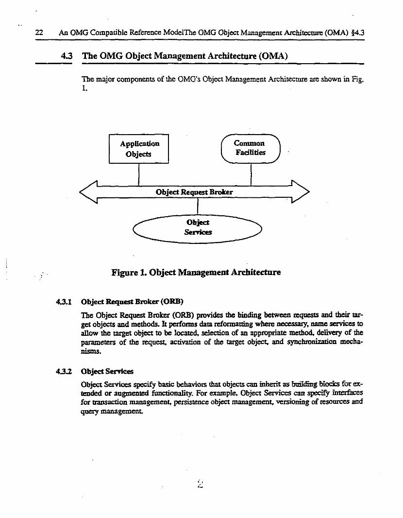
4.3 The OMG Object Management Architecture (OMA) ----The major components of the OMG's Object Management Architecture are shown in Fig. 1.
Application Objects
Object Request Broker
Object Senices
Common Facilities
Figure 1. Object Management Architecture
4.3.1 Object Request Broker (ORB)
The Object Request Broker (ORB) provides the binding between requests and their target objects and methods. It performs data reformatting where necessary, name services to allow the target object to be located, selection of an appropriate method, de1ive:ty of the parameters of the request, activation of the target object, and synchronization mechanisms.
4.3.2 Object Services
Object Services specify basic behaviots that objects can inherit as bailding blocks for extended or augmented functionality. For example. Object Services can specay interfaces for transaction management, persistence object management, versioning of resomces and query management.
§4.4 An OMG Compatible PASS Architectural Model An OMG Compatible Reference Model 23
4.3.3 Common Facilities
Common Facilities comprise objects and interfaces that are useful across many problem domains. Examples include error reporting, help facility, printing and spooling and reusable user interfaces.
4.3.4 .i\.pplication Objects
Application Objects are the application or domain-specific objects that comprise the 111ain conceptual framework for an application. These build upon the common facilities and object services to create complete applications.
4.4 An OMG Compatible PASS Architectural Model
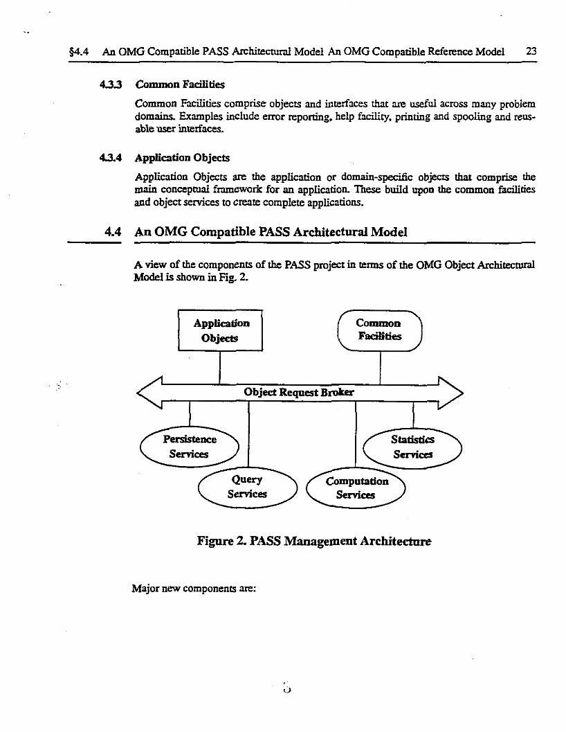
A view of the components of the PASS project in tenns of the OMG Object Architectural Model is shown in Fig. 2.
Application Objects
Persistence
Services
Object Request Broker
Services
Common Facilities
Statistics
Figure 2. PASS Management Architecture
Major new components are:
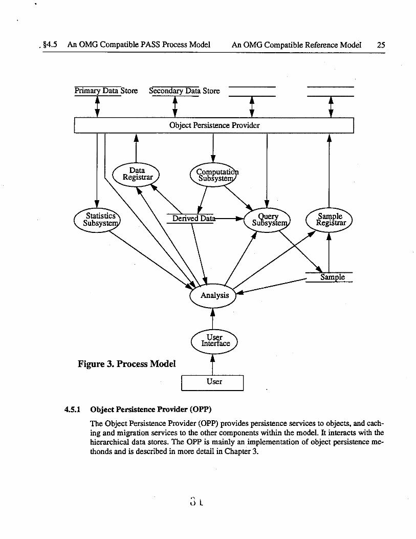
§4.5 An OMG Compatible PASS Process Model An OMG Compatible Reference Model 25
Primary Data Store Secondary Data Store
t t Object Persistence Provider
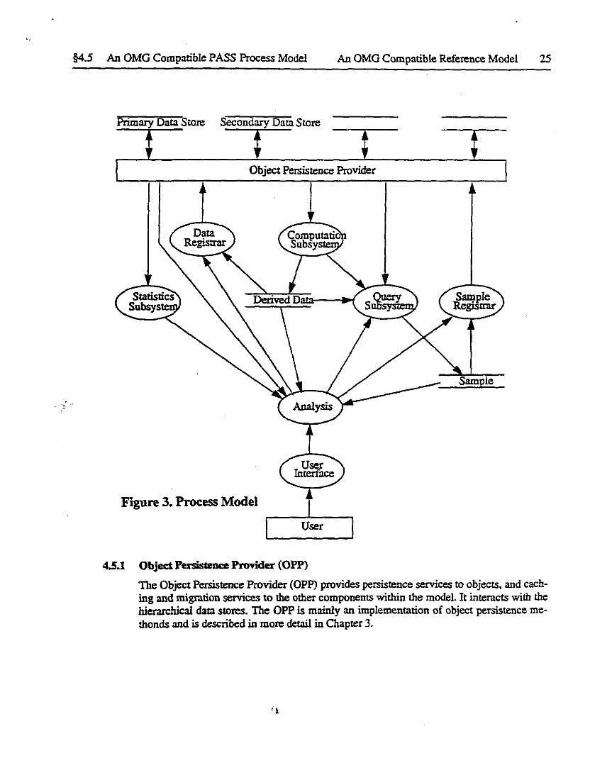
Figure 3. Process Model
User
4.S.1 Object Persistence ProTider (OPP}
The Object Persistence Provider (OPP) provides persistence services to objects, and caching and migration services to the other components within the model. It interacts with the hierarchical data stores. The OPP is mainly an implementation of object persistence me· thonds and is described in more detail in Chapter 3.
't

§4.6 An OMG Compatible PASS Communication ModelAn OMG Compatible Reference Model 27
· . . = ..
Application
Query Services Computation
Adaptor Services Adaptor
Query Services Computation Services
Broker Broker
Object Request Broker
Query Engines Computation Engines
· Figure 4. Communication Model
4.6.1 Query Services Adapter (QSA)
The Query Services Adapter (QSA) forms the inteiface between the application adn the Query Services Provider from Fig. 3 ..
4.6.2 Query Services Broker (QSB)
The Query Services Broker (QSB) performs the following functions:
• It distributes queries across the multiple Query Engines.
• It combines the partial results from each Query Engine to form the final query re· suits.
• It interacts with the Computation Services Broker to perform resouce allocation and optimization.
4.6.3 Query Engine (QE)
A Query Engine performs a query on an input collection. It can make requests to the Computation Services Provider for access to derived data as well as accessing persistent information.
;- .
28 An OMO Compatible Reference Mode!An OMG Compatible PASS Communication Model §4.6
4.6.4 Computation Services Adapter (CSA)
The Computation Services Adapter (CSA) forms the interface between the application code and the Query Services Provider from Fig 3.
4.6.5 Computation Services Broker
The Computation Services Broker (CSB) acts as the agent that performs the following functions.
• It interacts with the Computation Services Broker to perform resource allocation and optimisation.
4.6.6 Computation Engines (CE)
A Computation Engine is an object that has been registered within the PASS environment and has a well-defined transformation function on input persistent data. The result of the transformation is derived data in the form of transient objects. Within the HEP application domain, one class of CE might perform track reconstruction. another might perform vertex finding etc. Multiple instances of each type of Computation Engine may exist within the system, their allocation being managed by the Computation Services Broker in conjunction with the Query Services Broker.
' . lJ

An Architectural Model for the Petabyte Access and Storage Solutions
(PASS) Project
DRAFT 18 June 93
PASS Collaboration

ABSTRACT
[The abstract is missing]

§ 3
1 Introduction 6
1.1 Introduction 6
2 Requirements 7
2.1 Operational Requirements 7 2.1.1 Input DataRate & Size 7 2.1.2 The Role of Offline Computing 8 2.1. 3 Traditional Processing 9 2.1.4 A Database Approach 10
2.2 Technical Requirements 11
3 Reference Model 13
3.1 Introduction 13 3.1.1 Basic Concepts 13
3.2 Data model 14 3.2.1 Overview 14 3.2.2 Objects 14 3.2.3 Collections 14 3.2.4 Registered Collections 14 3.2.5 Functions 14 3.2.6 Queries 15
3.3 Process model 15 3.3.1 Requests 15 3.3.2 Clients and Servers 15
3.4 Persistence 15 3.4.1 Persistent IDs 16 3.4.2 Persistent Folios and Segments 16 3.4.3 Physical Addresses 16
3.5 Data Network 16 3.5.1 Nodes 16 3.5.2 Connections 17
3.6 Requests and Brokers 17 3.6. l Requesting a Persistent Object: Overview 17 3.6.2 Persistent Object Broker 18 3.6.3 Persistent Folio Broker 18 3.6.4 Persistent Folio Mover 18 3.6.5 Query, Compute, and Statistical Broker 18
3. 7 Dictionaries 18 3.7.1 Schema 18 3.7.2 Object Dictionary 19 3.7.3 Folio Dictionary 19 3.7.4 Application Metadata Dictionary 19
4
3.7.5 Registered Collections
4 An OMG Compatible Reference Model
4.1 Introduction 4.2 The OMO Object Model
4.2.1 Objects 4.2.2 Clients 4.2.3 Servers 4.2.4 Requests 4.2.5 Interfaces 4.2.6 Methods.
4.3 The OMO Object Management Architecture (OMA) 4.3.1 Object Request Broker (ORB) 4.3.2 Object Services 4.3.3 Common Facilities 4.3.4 Application Objects
4.4 An OMO Compatible PASS Architectural Model 4.4.1 Persistence Services 4.4.2 Query Services 4.4.3 Computation Services 4.4.4 Statistics Services
4.5 An OMO Compatibie PASS Process Model 4.5.1 Object Persistence Provider (OPP) 4.5.2 Query Service Provider (QSP) 4.5.3 Computation Service Provider (CSP) 4.5.4 Statistics Service Provider (SSP) 4.5.5 Data Registrar
4.6 An OMO Compatible PASS Communication Model 4.6.1 Query Services Adapter (QSA) 4.6.2 Query Services Broker (QSB) 4.6.3 Query Engine (QE) 4.6.4 Computation Services Adapter (CSA) 4.6.5 Computation Services Broker 4.6.6 Computation Engines (CE)
5 Policy Issues
5.1 Policy Issues 5.2 Parallelization strategies
5.2.1 Hierarchical Processing 5.2.2 Returned data sets 5.2.3 Physics query language 5.2.4 Tools for physicists 5.2.5 Numerical Examples
1U
§
19
20
20 21 21 21 21 21 21 21 22 22 22 23 23 23 24 24 24 24 24 25 26 26 26 26 26 27 27 28 28 28 28
29 29 29 30 31 33 33 34

§
6 Implementation Models
40
6.1 SSCL Testbed 6.1.1 Data Management Functionality 6.1.2 Tertiary Storage 6.1.3 Parallelism
6.2 Generic Model 6.3 SDC/GEM Model
• .1 j_
35
35 37 37 37 38 38
5
1 Introduction
1.1 Introduction
PASS (Petabyte Access and Storage Solutions) is an R&D project aimed at solving the data storage and access problem for the new generation of data-intensive scientific programs. Target projects include high energy hadron colliders such as the Superconducting Super Collider (SSC) in Texas and the Large Hadron Collider (LHC) at CERN, Switzerland, experiments at heavy ion colliders such as RIIlC, the Earth Observing Satellite system, Human Genome database, and Global climate simulations.
This document contains three major sections that detail the requirements for the system, an abstract reference model that identifies components and mechanisms within the system and finally some implementation models that address some of the policy issues omitted from the reference model and address specific projects. The models identified here are not optimized and should be viewed as working drafts which will be refined as our understanding of the nature of the problem and applicable solutions is refined. They are presented as models in which some care has been given to the value of parameters and major architectural questions so that the various components will to first order work together. The models are intended to form the basis for further work by (a) making choices that can be tested by specific scenarios for their use and (b) ideas for elaboration or better ways of accomplishing various aspects can be examined in the context of "working" models where all aspects can be taken into account.

2 Requirements
2.1 Operational Requirements
The requirements are taken from a specific scientific problem (analysis of data from a major SSC experiment) but are expected to be appropriate for other problem domains.
2.1.1 Input Data Rate & Size
High Energy Physics (HEP) experimental data are mainly organized as a sequence of events, each event containing the information from the many individual detector channels for a single trigger of the detector. These raw data, and additional derived data produced by further processing, are highly hierarchical in structure. Each detector subsystem (tracking, calorimetry etc.) produces its own variety of data, which in turn is divided up into data from the components of the subsystem (e.g. inner, central and intermediate angle tracking). As. analysis is performed, these subsystem data are refined and organized (e.g. collections of tracking system space coordinates recognized as belonging to a 3-D track) and additional connections are created between data from different subsystems. For example, a track in the tracking subsystem might be correlated with a cluster of energy in the calorimeter subsystem.
Each raw event may contain 0.3 to 2 MB of compressed data, having an average size of I MB. The event rate, which is determined by the underlying physics processes and the hardware trigger systems, may typically be 10-lOOHz, leading to a primary data storage requirement of 10-lOOMB/sec. The role of the online system is to record this information

8 Requirements Operational Requirements §2.l
in real time onto permanent storage media. Traditionally this has been magnetic tape, but the aim of this project is to evaluate alternatives to this, in particular the feasibility of using a distributed hierarchical mass storage system in which magnetic tape may play a role, but which might use a variety of storage technologies.
Each event is essentially independent, the exception being that detector-specific quantities may apply to sequences of events, typically referred to as a data taking run. These calibration quantities are used to convert the electrical information from the detector into physically meaningful quantities such as the location and energy of charged particles. The goal is to make these calibrations prior to taking the data, but some of them are derived from the data themselves, requiring an iterative analysis model. Thus the initial analysis might make some assumptions that prove to be incorrect and may need to be repeated with some systematic corrections derived from the analysis itself.
2.1.2 The Role of Offiine Computing
The role of the offline computing system is the following:
(a) Refine the trigger decisions to eliminate events that correspond to uninteresting physics processes, but which the online trigger systems did not detect due to the harsh time constraints under which they operate.
(b) Reconstruct the event to recover the momenta, energies and types of the particles produced. Depending on the physics process, many lOOs of particles may be produced for each event, each having different trajectories and properties. The reconstruction process adds information to each event, but might not be fully applied to every event, depending on the exact sequence with which this process is combined with (a) above. This phase typically results in a doubling of the overall event siz.e.
(c) Categorize events according to the underlying physics processes. These processes may represent both conventional physics, where the results may provide normalizations, or new physics, reflecting new processes occurring at the high collision energies provided by these accelerators. A typical experiment may identify 20-50 such categories. An event may be assigned to multiple categories.
(d) Allow a large body of physicists (-1000) to perform repetitive analyses on the resulting events, combining the data from selected event samples into summary plots which may be used to apply filter cuts to further refine the event sample.
(e) Repeat reconstruction on selected events, perhaps with a new set of constraints being applied (e.g. secondary vertices) as a result of further understanding achieved from (d) above. Another reason for redoing event reconstruction may be systematic errors caused by the detector systems themselves. Only by analysing a large sample of events may such systematic effects be identified and then rectified by re-analysis.
The physicists who wish to examine these data are geographically dispersed, the experiments being organized as international collaborations of physicists from many (-100) dif-
• J. 'i
§2.1 Operational Requirements Requirements 9
ferent institutions throughout the world. Each physicist will tend to focus on a few categories of events, but the group of physicists focussing on a particular category may itself be geographically dispersed.
The nature of the computing changes as events progress down this analysis chain. The initial stages, particularly (b) above, are computationally intense and must be performed in a well-controlled environment in order to minimize redundant processing. The later stages require fast, immediate access to the specialized data sets. Analysis will be performed repeatedly, involving the computation of derived information, but much of the process will be filtering of events on the basis of existing information and collection of histograms or other visualization tools that provide quantitive or qualitative insight into patterns in the data and hence the underlying physics processes. Hence the focus must be on rapid tum-around which in tum implies the use of parallel processing techniques. To the extent possible, the data access and analysis system should permit the physicist to use time to consider the implications of the data and to devise strategies for further analysis, rather than spending much of the time waiting for the previous analysis step to be completed.
Analysis of data that has already been collected into refined data sets of up to 1 TB should have as a goal a completion time of under one hour. During that time, partial results should be made available to the physicist for display or statistical analysis. The study of such partial results may often allow the physicist to understand what is needed for the next step before the current analysis is completed. In that case it may be desirable to be able to terminate the initial analysis before completion.
The above discussion places both bandwidth and processing requirements on the analysis system and must be considered in the context of the large, geographically dispersed user community.
2.1.3 Traditional Processing
The traditional approach is for the online system to write the raw event data onto magnetic tape or similar storage media. An offline production system, typically centrally located, performs sequential processing of the events in a series of passes over the data. Each pass corresponds to one of the items identified above. Thus Pass 1 might perform a preliminary event reconstruction; Pass 2 might filter events and split them into output streams corresponding to the event categories; and Pass 3 might fully reconstruct events, etc. Initially information will be added to each event, corresponding to the reconstructed quantities, but then a process of refinement takes place, where both the number of events is decreased through the use of filters appropriate for each category, and also the amount of information for each event is reduced, keeping only the minimal information by which the underlying physics processes can be examined. This refinement is typically hierarchical, resulting in the production of Data Summary Tapes (DSTs), of which there might be several (DST, miniDST, microDST, nanoDST, etc.) corresponding to the degree of data compression that each has undergone.
. ' J_.,
10 Requirements Operational Requirements §2.I
Following the production stage, the physicists perform their interactive analyses on the event samples contained in the DST sample appropriate for their category of events. If these analyses indicate that events need to be reconstructed again, the events must be located in the bulk production system and re-analysed since the required information has typically been dropped in producing the summary DSTs.
These traditional systems may be categorized as hierarchical refinement involving multiple sequential scans over the data.
2.1.4 A Database Approach
An alternative scenario assumes that all the events being generated by the online data collection system are stored directly onto a database of some sort. Subsequent processing and analysis is performed by accessing the event data from this database. As each event is processed, more information is added to it, reflecting the additional understanding of its properties and the underlying physics processes. Event samples would be made by grouping classified events into database collection objects.
Note that the above discussion is not meant to imply that all the data for an event should be located close together. Depending on the particular analysis, a subset of the data from many different events might be more optimally clustered together and the optimal organization might well depend on the history of the access patterns.
The different phases of offiine reconstruction and analysis, together with the geographical dispersion of the physicists and their interest in different categories of events, lead to that requirement that the system support hierarchical datastores. One possible scenario for the organization of these datastores is:
• Collaboration DataStore. This is the master datastore into which the online system writes the raw data.
• Regional DataStores. These duplicate some of the data in the Collaboration DataStore and contain collections of events and derived data that have been selected for further study. There might be -10 such Regional stores.
• Working Group DataStores. These consist partly of collections of events that have been cached from the Regional DataStore to local clusters for greater efficiency, and partly of data that have been migrated from Individual DataStores in order that they be accessible to a wider audience. There might be -100 such Working Group stores, corresponding to each Institute within the collaboration.
• Individual DataStores. These consist mainly of the collections resulting from querying a Working Group or Regional DataStore. There might be -1000 such Individual stores, corresponding to the individual end users.
This database approach can be compared to a hierarchy of cache memories, with data being cached or migrated on the basis of the access patterns.
. ' J. \'

§2.2 Technical Requirements Requirements 11
2.2 Technical Requirements
Bandwidth.
Since the duty factor for the experiments is high (they expect to run continually for significant portions of the calendar year), data must be loaded into the Collaboration DataStore at a rate approximately equal to that at which it is being recorded by the online system. This implies a bandwidth of 10-lOOMBytes/sec.
Concurrency.
Because of the high duty factor, access to the data in the Collaboration DataStore must take place concurrently with loading of this Store. This implies that loading of the DataStore must be implemented in such a manner that transaction collisions are minimized.
Since the hierarchical datastores may be accessed by many clients simultaneously, some requiring only read access, but others requiring write access to the datastores, the database system must support true transaction processing to prevent simultaneous modification of the same data. Note that only in rare cases will actual modification to existing data occur, the more normal situation being that a new version of some data needs to be created.
Checkpointing.
Many of the transactions, particularly in the reconstruction phase, are very time-consuming. The availability of checkpointing and transaction roll-backs is essential to ensure correct data integrity and to minimize wasted processing cycles.
Uniformity.
There should be uniform access to all data, regardless of whether they reside in the primary Collaboration DataStore, an intermediate datastore or locally on the physicist's desktop.
Scalability.
The same software technology, combined with the appropriate hardware, should support databases ranging from the complete event sample, to small samples of events that an individual physicist might wish to use for a simple analysis.
Clustering
A particular physics analysis may indicate that logically diverse data objects are commonly accessed as a group. The database should support clustering of such objects together in order to improve performance.
Extensibility.
. ')
J. I

12 Requirements Technical Requirements §2.2
During the course of processing, additional information may be added to an event The database must support a data model allowing such extensions to be made.
Data versioning.
Throughout the lifetime of an event, several different reconstructions may be attempted, corresponding to different calibrations or constraints. The data model should support such data versioning. Another possible role for data versioning is to support the creation of smaller, workgroup databases containing a replication of a subset of the original data that is hence more optimally available, perhaps at a secondary computing center, for access by a small group of users. This concept can be extended to the individual physicists and their desktop workstations.
Schema versioning.
It is highly desirable that some sort of schema versioning be supported by the database since it is possible that changes in the data model will be made throughout the lifetime of an experiment. Given the enormous quantity of data, it is essential that the database support incremental versioning where an object is updated as it is accessed rather than requiring bulk updating. Updating should be static in that each object should only require updating once, subsequent accesses returning the updated object
Access Control.
The database must support access control whereby the ability to make modifications may be limited to those people having the appropriate authorizations. Furthermore, since the database is foreseen as being hierarchical, with data migrating closer to the end user depending on the access patterns, such access control must also be hierarchical, allowing different authorizations at each level of the hierarchy.
Sample libraries.
The database should support creating persistent objects corresponding to collections of the physics data of interest. These would then allow for queries to be made on standardized data samples.
Query Language.
Many queries are characterized by significant processing being performed in code written by the application physicist in the language of their choice (typically Fortran). Thus the database must support a query language allowing callout to external routines.
~ . J. ()

3 Reference Model
3.1 Introduction
3.1.1
1 •
;j' 11,iK f-iu~ -~l'!r•.;1 +- 1•\i''-~t\ ""'\r
,_J \ ·-~ l./:..--'
We describe a reference model for working with a distributed persistent store of complex objects and an interface between the store and a hierarchical storage system.
Basic Concepts
The model described here for distributed object computing uses just three primary concepts:
Obje~ts. The data is assumed to be organized into objects.
:__ Proce;sliS?Computation consists of communicating processes which act upon objects. -------------- . - -
Networks. Data and processes are distributed among nodes in a network, with two nodes being able to exchange objects in case there is a path connecting them.
In addition, the following three concepts, which are defined in terms of the basic concepts, are also important:
Persistent Objects. Objects may be persistent, which means that they may be accessed independently of the process which created them. Otherwise, objects are called transient
Brokers. Processes may make request of other processes, called brokers, to take certain actions on objects. Requests to brokers are transported across the network in a transpar-
l ;J

14 Reference Model Data model §3.2
ent fashion.
Folios. For efficiency, objects and collections are collected into physical units called folios, which the system manages. Components of the system respond to distributed requests for objects, folios, and pieces of folios called segments.
Each of these concepts is described in more detail in the sections below.
3.2 Data model
3.2.1 Overview
We begin with an overview of the data model. We assume that the items of interest are objects; that objects are collected into one or more collections; and that stores consist of objects and collections.
Queries accept an input collection of objects and produce an output collection by selecting objects and computing derived objects.
3.2.2 Objects
The data of the system is divided into objects; objects have attributes; when functions or processes act upon objects, they are sometimes called methods. Objects which share the same attributes and methods form classes.
3.2.3 Collections
Instances of objects can be gathered togethered into logical units, called collections. Collections may contain the actual objects themselves or pointers to the objects. Ordered collections are lists; unordered collections are called either sets or bags, depending whether or not duplicates are allowed. Collections are themselves objects; as such, they may support specialized access methods to access their elements, such as hashing or B+ trees.
3.2.4 Registered Collections
A collection is called registered in case it can be accessed by processes making requests to a broker asking for the collection by its properties instead of its name. Processes may register collections by sending the name of the collection to a broker, together with (some) of its properties.
3.2.5 Functions
A function, or method, is simply a means of acting upon an object. The result may be a void or another object.
:..:u

§3.3 Process model Reference Model 15
3.2.6 Queries
Since collections are themeselves are objects, functions may be applied to collections. If the result is another collection, the function is called a query. Notice that this definition of query includes queries that select objects for inclusion into the output collection, queries that compute new objects from the input objects, and queries which both select objects and compute new objects. When new objects are produced by a query, this additional data is sometimes called derived data.
3.3 Process model
Processes are the components of the model which act upon objects. Processes may create, store, access, or modify objects themselves, or may request that other components of the system called brokers take such an action. After receiving such a request, the broker may take an action or forward the request to another broker for action. Requests are transported across the network to the appropriate broker in a transparent fashion, and objects are returned to the requesting process transparently.
We assume that a computation consists of communicating, distributed processes. Processes may communicate with each other through a variety of mechanisms, including client-server connections, and peer-to-peer connections.
Note that a query can be viewed as a sequence of processes, which take input collections to output collections. Formally, processes are finite state automata.
3.3.1 Requests
As mentioned, a process may make a request to a broker for a specific object. If the request is successful, the object is returned to the process which requested it; otherwise, a failure is returned.
3.3.2 Clients and Servers
A process which requests an object from a broker is also known as a data client. A broker responding to a request for an object is also known as a data server. Requests and objects are transported transparently across the data access network.
3.4 Persistence
We say that an object is persistent in case its existence is independent of the existence of the process which creates it. Objects which are not persistent are called transient. In particular, objects and collections of objects may be persistent, since as remarked above, collections of objects are also objects.
,, G .l

16 Reference Model Data Network §3.5
In practice, persistence objects are distributed and are stored in a transparent fashion on disk or some other permanent media, such as tape.
In order to be managed more efficiently, objects are gathered together into physical units called folios. Objects are extracted from folios by the Persistent Object Broker (de- ; , scribed below). Folios are extracted from bitfiles by the Persistent Folio Mover Broker ', n """ (described below). Bitfiles are managed by the hierarchical storage system. j
3.4.1 Persistent IDs
We assume that each persistent object is assigned a unique id, called a persistent id and that each object belongs to one persistent store or store. ·
3.4.2 Persistent Folios and Segments
We also assume that each store is physically divided into folios, and each folio is physically divided into segments. Objects may span one or more segments, and even one or more folios. We assume that each folio has a folio id attached to it each segment has a segment id attached to it.
3.4.3 Physical Addresses
Persistent objects must be stored on some permanent media_;_ because of this, each persistent object is associated with a physical address. For eiiinple, a persistent object may have a virtual memory address or byte location within a file associated to it in this way. Note that this physical address may change. For example, this happens if the object is cached or migrated. In addition, each object may have a logical id associated to it. By assumption, this does not change, despite any changes to the object.
There are several possiblities:
(a) The pid is always the physical address just described.
(b) The pid is always the logical id and a table is maintained between the physical addresses and the logical ids.
(c) The pid is sometimes the physical address and sometimes the logical id; tables are maintained as necessary. The pid is said to swizzle between the two.
3.5 Data Network
3.5.1 Nodes
The data network consists of nodes. A node is an abstraction of a computing, storage, or other type of device. Nodes are connected to each other by edges. Each edge has an associated data rate. In addition, some nodes are labeled with capacities or processing rates.
§3.6 Requests and Brokers Reference Model 17
In other words, a network is a graph, with the nodes verticies and the edges labeled by the appropriate data rate. For example, a networked workstation may be modeled by a graph with the following nodes:
(a) a node representing the cpu, labeled with by its flops
(b) a node representing the memory of the workstation, labeled with its capacity
( c) a node representing a local disk, labeled with itscapacity
( d) several nodes representing remote networked disks, labeled with their capacities
(e) several nodes representing other workstations in the the local cluster
(f) a node representing a gateway to the rest of the network
In addition the nodes would be connected by edges as appropriate and labled with the appropriate data rate.
3.5.2 Connections
Two nodes may communicate with each other if there is a path from one to the other; that is, if there is a sequence of edges connected one to the other. The two nodes may transport requests and objects at a data rate which is the minimum of the data rates of the edges comprising the path connecting the two nodes. Since paths are not necessarily unique, two nodes may communicate at different data rates depending upon the communication path. If two nodes are connected they may exchange requests and objects in a transparent fashion.
3.6 Requests and Brokers
A process attached to a node may request an object from one is known as a broker. Some important types of brokers are described in the rest of this section.
I !! _\ ::_" '
3.6.1 Requesting a Persistent Object: Overview \~ _f" \.().-_;.·'
The Persistent Object Broker implements persistence for complex objects. If the Persistent Object Broker determines that the object requested isnotm a folio currently available, it sends a request for the folio to the Persistent Folio Broker. The Persistent Folio Brokers determines the bitfile containing the folio and sends a request for the bitfile to the Bitfile Server, part of the storage system. The bitfile is returned by the Bitfile Mover, also part of the storage system, to the Persistent Folio Broker, which extracts the folio from the bitfile, loads the persistent folio into the space of persistent objects, and sends a reply to the Persistent Object Broker indicating that the folio is loaded. Queries are processed by the Query Broker to produce a list of requested persistent objects, which is passed to the Persistent Object Broker. In addition, applications may request persistent objects from the Persistent Object Broker directly.
See Figure- I.

18 Reference Model Dictionaries §3.7
3.6.2 Persistent Object Broker
The Persistent Object Broker is responsible for creating, storing, and accessing complex persistent objects. A subcollection of the objects in the persistent store are in memory, or virtual memory, at any one time. The Persistent Object Broker is also responsible for r , ~ moving objects from memory to permanent storage as necessary so that objects may per-sist after the process which created them terminates,~d so iliai: persistent objects may be accessed in essentially the same way as transient objects.
3.6.3 Persistent Folio Broker
We assume that from the pid of an object it is possible to infer the folio which holds the object. If the Persistent Object Broker requests an object with a pid corresponding to a folio which is not available in (virtual) memory, it faults, and generates a request for the folio to the Persistent Folio Broker. The Persistent Folio Broker then determines the bitfile containing the persistent folio and sends a request to the Bitfile Server, which is part of the storage system, for the bitfile. The Persistent Folio Broker also sends a message to the Persistent Folio Mover that the specified persistent folio is required.
3.6.4 Persistent Folio Mover
In response to a request to the Bitfile Server for a bitfile, the storage sytem responds by moving the bitfile from the Bitfile Mover, which is part of the storage system, to the Persistent Folio Mover. The Persistent Folio Mover extracts the folio from the bitfile, loads it into (virtual) memory, and sends a reply to the Persistent Object Broker indicicating that the persistent folio has been loaded.
3.6.5 Query, Compute, and Statistical Broker
Other brokers handle distributed requests for queries and various computations on persistent objects by making the appropriate requests to the Persistent Object Broker. Queries on local transient objects are handled as usual by the application. In principle, one can request transient non-local objects by making the appropriate request of a suitable broker.
3. 7 Dictionaries
3.7.1 Schema
Each persistent object is a member of a class. The information describing the class is contained in the schema dictionary.
§3.7 Dictionaries Reference Model 19
I
I i
l
3.7.2 Object Dictionary
This contains lists of all the objects, their storage location, the collections they belong to, their indicies, and similar information.
3. 7 .3 Folio Dictionary
This contains a list of all persistent object folios, the associated segments, their locations, and related information.
3.7.4 Application Metadata Dictionary
3.7.S
This contains various types of summary information about objects and collections of objects. The exact information contained is specified by the persistent store administrator. For example, this may include information about collections and collections of collections.
Registered Collections
This contains a list of all registered collections, including various of their properties. Registered Collection Brokers use these dictionaries to access registered collections by their properties.
,, ' "'"0

4 An OMG Compatible Reference Model
4.1 Introduction
This chapter describe a reference model that conforms to the definitions and terminology for the object model from the Object Management Group (OMO) [l]. It uses the concept of an Object Request Broker (ORB) to provide the mechanisms by which objects transparently make requests and receive responses. The ORB provides interoperability between applications on different machines in heterogeneous distributed environments and seamlessly interconnects multiple object systems1. The Common Object Request Broker Architecture is discussed in more detail in Ref. [2].
1. From Object Management Arrhitecture Guide, Revision 1.0, OMG TC Document 90.9.1.
,, ' c.u

§4.2 The OMO Object Model An OMO Compatible Reference Model 21
4.2 The OMG Object Model
4.2.1 Objects
An object is an encapsulated entity (i.e. with a well-defined interface) that provides one or more services that can be requested by another object. There are several components to an object system.
4.2.2 Clients
A client is an object that makes a request for a service provided by another object.
4.2.3 Servers
A server provides one or more services that may be requested by other client objects. A server object may itself make requests of other server objects and may therefore be considered a client of those other servers.
4.2.4 Requests
Clients reque.st services by issuing requests. A request causes a service to be performed on behalf of the requesting client. The information associated with a request specifies a target server object, an operation and zero or more parameters. The operation identifies the service to be performed and the parameters specify both the objects that are to participate in providing the service and any other information needed to specify the result.
4.2.5 Interfaces
An interface is a description of the available services provided by a server object. In the OMG model, the interface is specified in the Interface Definition Language (IDL). The interface the client sees is completely independent of the location of the server, what programming language it is implemented in and the communication protocols used. An object can inherit characteristics from one or more ancestor objects.
4.2.6 Methods.
The code that is executed to perform an operation is called a method. When a client issues a request a method of the target object is called. The input parameters are passed to the method, after any necessary data reformatting has been performed and the output parameters and return value, if any, are passed back to the requestor.
("\I '
?, I

22 An OMO Compatible Reference ModelThe OMO Object Management Architecture (OMA) §4.3
4.3 The OMG Object Management Architecture (OMA)
The major components of the OMO's Object Management Architecture are shown in Fig. 1.
Application Objects
Object Request Broker
Object Services
Common Facilities
Figure 1. Object Management Architecture
4.3.1 Object Request Broker (ORB)
The Object Request Broker (ORB) provides the binding between requests and their target objects and methods. It performs data reformatting where necessary, name services to allow the target object to be located, selection of an appropriate method, delivery of the parameters of the request, activation of the target object, and synchronization mechanisms.
4.3.2 Object Services
Object Services specify basic behaviors that objects can inherit as building blocks for extended or augmented functionality. For example, Object Services can specify interfaces for transaction management, persistence object management, versioning of resources and query management.
, .... '. c. ()

§4.4 An OMG Compatible PASS Architectural Model An OMG Compatible Reference Model 23
4.3.3 Common Facilities
Common Facilities comprise objects and interfaces that are useful across many problem domains. Examples include error reporting, help facility, printing and spooling and reusable user interfaces.
4.3.4 Application Objects
Application Objects are the application or domain-specific objects that comprise the main conceptual framework for an application. These build upon the common facilities and object services to create complete applications.
4.4 An OMG Compatible PASS Architectural Model ----A view of the components of the PASS project in terms of the OMG Object Architectural Model is shown in Fig. 2.
Application
Objects
Persistence
Object Request Broker
Query Services
Common Facilities
Figure 2. PASS Management Architecture
Major new components are:
''"" f J ~:
24 An OMG Compatible Reference Model An OMG Compatible PASS Process Model · §4.5
4.4.1 Persistence Services
4.4.2 Query Services
4.4.3 Computation Services
4.4.4 Statistics Services
4.5 An OMG Compatible PASS Process Model
A process view of the PASS Model is shown in Fig 3. The model described here is targetted towards the HEP analysis problem and therefore has components that are specific to that domain. However, the overall organization and relationships between the components is appropriate for a wide range of problem domains.
Note that the ORB does not appear explicitly on this process view since its functions are represented by the communication arrows between components. The major components are described in the following sections.
" ' ,,u
. §4.5 An OMG Compatible PASS Process Model An OMG Compatible Reference Model
Primary Data Store Secondary Data Store
t t Object Persistence Provider
Figure 3. Process Model
User Interface
User
4.5.1 Object Persistence Provider (OPP)
Sample Registrar
Sample
25
The Object Persistence Provider (OPP) provides persistence services to objects, and caching and migration services to the other components within the model. It interacts with the hierarchical data stores. The OPP is mainly an implementation of object persistence methonds and is described in more detail in Chapter 3.
" 0 l
26 An OMO Compatible Reference Mode!An OMO Compatible PASS Communication Model §4.6
4.5.2 Query Service Provider (QSP)
The Query Service Provider (QSP) provides query services to the application. As described earlier, a query is an operation on an input collection and results in a new collection and possibly other derived information. This model differentiates between this QSP that operates on already existing persistent information and the Computation Service Provider (see next section) that can create derived information. This derived information can be used directly by the application or by the QSP and can itself be made persistent by the Data Registrar.
The interface between the Analysis Application and the Query Service provider is described in more detail in Section 4.4.x
4.5.3 Computation Service Provider (CSP)
The Computation Service Provider (CSP) is responsible for performing computationally,' ",' /, intensive operations using persistent objects as input It creates transient, ~erived informa-i '-tion for use by its £l~e_n_ts, e.g. the Query Service provider and the Analysis Application. /
The interface between the Analysis Application and the CSP is described in more detail in Section 4.4.x
4.5.4 Statistics Service Provider (SSP)
The Statistics Service provider (SSP) operates on result collections and forms histograms or similar visual aids by which the end user may make qualitative and quantitative decisions to effect the future processing of data.
4.5.5 Data Registrar
The Data Registrar is responsible for taking transient information and making it persistent. This information will typically be derived data from the Computation Subsystem, or collections that result from query operations.
4.6 An OMG Compatible PASS Communication Model
The PASS Communication Model for PASS is shown in Fig 4 .
... . , t._) i...

§4.6 An OMG Compatible PASS Communication ModelAn OMG Compatible Reference Model 27
Application
Query Services Computation
Adaptor Services Adaptor
Query Services Computation Services
Broker Broker
Object Request Broker
Query Engines Computation Engines
Figure 4. Communication Model
4.6.1 Query Services Adapter (QSA)
The Query Services Adapter (QSA) forms the interface between the application adn the Query Services Provider from Fig. 3 ..
4.6.2 Query Services Broker (QSB)
The Query Services Broker (QSB) performs the following functions:
• It distributes queries across the multiple Query Engines.
• It combines the partial results from each Query Engine to form the final query results.
• It interacts with the Computation Services Broker to perform resouce allocation and optimization.
4.6.3 Query Engine (QE)
A Query Engine performs a query on an input collection. It can make requests to the Computation Services Provider for access to derived data as well as accessing persistent information.
" l) ,)
28 An OMO Compatible Reference ModelAn OMO Compatible PASS Communication Model §4.6
4.6.4 Computation Services Adapter (CSA)
The Computation Services Adapter (CSA) forms the interface between the application code and the Query Services Provider from Fig 3.
4.6.5 Computation Services Broker
The Computation Services Broker (CSB) acts as the agent that performs the following functions.
• It interacts with the Computation Services Broker to perform resource allocation and optimisation.
4.6.6 Computation Engines (CE)
A Computation Engine is an object that has been registered within the PASS environment and has a well-defined transformation function on input persistent data. The result of the transformation is derived data in the form of transient objects. Within the HEP application domain, one class of CE might perform track reconstruction, another might perform vertex finding etc. Multiple instances of each type of Computation Engine may exist within the system, their allocation being managed by the Computation Services Broker in conjunction with the Query Services Broker.
" tJ It

5 Policy Issues
5.1 Policy Issues
This Chapter discusses some policy issues not detailed in the Reference Model which deals with the mecahnisms and components.
5.2 Parallelization strategies
Queries directed to a very large database of essentially independent events are natural candidates for data parallelism. This most basic of approaches may in fact be the most effective. The idea is that multiple processors would each apply a complete query to disjoint portions of the database, and pipe their output to a single process that would merge the results.
Another approach to parallelism is to pipeline query processing. Suppose a query of the form "SELECT a FROM b WHERE c" is issued, and the collection corresponding to b resides on a number of tapes. Such an approach might have one set of processors handling tape input of entire event objects and passing these to another set of processors. These processors might apply the WHERE criteria and pipe the qualifying events to another set of processors that would in turn cull the data according to the SELECT directive. The efficacy of the latter approach would depend strongly on such performance considerations as the quantity of data involved in the query, I/O and network characteristics. and processing power.
" r,_ u LI

30 Policy Issues Parallelization strategies §5.2
Queries
Throughout this draft, we shall use a pidgin Object-SQL to convey the sense of some sample queries. This usage is not intended to endorse selection of Object-SQL as the official query language of the PASS project
Positions taken with respect to issues addressed in this reference model are intended solely as starting points for discussion. They should not be construed as representing a project-wide consensus.
5.2.1 Hierarchical Processing
Query parsing for syntactic correctness should be handled as close to the point of query issuance as possible.
Complete query processing should be possible at this same level when the necessary data sets are local. For example,
USE mydata SELECT * FROM myevents WHERE event.number_of_muons()=2
should be executable on a physicist's workstation if mydata is local (and locally owned?). Failure of the network should not disable access to local data.
Once a query has been parsed for syntactic correctness, the local query handler determines whether direct local access to the requisite data is feasible.
If the local query handler cannot service a correctly posed query, e.g., it does not recognize the name in a USE statement, the query is passed up the system hierarchy for processing. A single query manager has responsibility for queries to a given data set The collaboration may choose to maintain a single query manager for all data owned by the collaboration at large.
It is the responsibility of the query manager to transform queries against data sets for which it is responsible into service requests directed to the requisite object manager(s).
Notes:
• A single query manager is responsible for entire data sets, even though one data set may be distributed over a number of systems.
• A query manager may be replicated for the sake of reliability and performance.
• It should be possible to direct a query to a specific query manager for the (rare?) cases when one-way traversal of the hierarchy is inadequate.
Once a query has been checked for correctness and its associated database resources located, there is some flexibility in how the query processing is divided among processors in the system hierarchy. Refer to the reference model section on parallelization strategies for related details.

§5.2 Parallelization strategies Policy Issues 31
It could be argued that partitioning the query processing workload is a matter of query optimization and should not be addressed by a reference model---a commercial objectoriented database with client/server capabilities, multiple server support, and its own approach to query processing should be admissible if it meets performance criteria and capability requirements. It is nonetheless instructive to consider several scenarios here.
One model suggests that application of selection criteria should take place as close to the location of the data as possible, and this is the model proposed in this draft The idea is that if sufficient processing power can be provided, maximizing performance means minimizing data transfer requirements. An alternative is to have processors near the data deal with only that portion of the query that cannot be handled elsewhere. This might mean, for example, processing "SELECT FROM" directives, and deferring all further work (e.g., WHERE handling) to processors further down the hierarchy. The idea is to minimize an individual user's load on system-wide resources, and to have the cost of query processing borne by the query issuer as much as possible.
Consider the following example.
USE Eventstore SELECT * FROM events WHERE event.number_of_Jlluons() = 2
Deferring WHERE processing could in this case mean moving a petabyte of data through the network. {\it (Say something about indexing here.)}
It may not be easy to do {\it all} query processing near the location of the required data. If the above example is modified to look like
USE Eventstore SELECT event_tag, tracks, particles FROM events WHERE event.number_of_muons() = 2 AND
myfunction(event.muons(l),event.muons(2)) > mythreshold
where myfunction is a user-supplied function and this query is being issued from within a code running on the physicist's workstation, then at least part of the data culling might need to be handled at the point of issuance.
5.2.2 Returned data sets
Returned data sets are collections of objects. It must be possible to name these collections and to render them persistent (e.g., the SQL "SELECT INTO" construct). Returned objects may be of a class already defined in the database, or may be instances of a new class derived by selection from existing objects, and may include any combination of new, old, and modified attributes. The database must support creation and use of such derived classes by individual physicists.
, ... ' . 0 I
32 Policy Issues Parallelization strategies §5.2
Significant technical issues arise when returned objects contain references to other objects. Recently proposed schema define Track objects, for example, that may contain Particles and Vertices. These references may be implemented as sets of pointers to Particle and Vertex objects. Such objects may themselves contain sets of pointers to other objects. When Tracks are returned in response to queries, are the corresponding Particle and Vertex objects returned also?
The situation is analogous to copying across links in file systems, and the preferred strategy may depend upon the circumstances. In any case, mechanisms must be provided to dereference any such pointers correctly. Advantages of not automatically copying across pointers include reduced data traffic in response to the initial query, increased efficiency if the pointers turn out never to be dereferenced, and the potential for improved data consistency and smaller storage requirements when the query response data is itself made persistent. Disadvantages include the potential for serious performance degradation if objects constituent to those returned by the query are needed later. (Imagine building a database on your workstation by means of a slow and expensive query to the Event Store, only to find more queries to the Event Store being generated dynamically every time you reference certain fields.)
Programmers may process collections of objects by directly traversing lists of pointers to those objects in. an essentially sequential fashion. In such scenarios, one could make a case for not copying across references---pointer dereferencing would simply lead to possible page faults, which would result in the appropriate page of event data being requested of and supplied by a remote database server on demand. (This is analogous to the Object Store model.) If the physical organization of the database has events stored contiguously, then this could be a very viable strategy unless the code were also to generate a persistent collection of objects from the query data, and those object definitions included references to other objects. In such cases, the same considerations described in the previous paragrah would apply.
See also the related discussions of object and volume managers elsewhere in this document.
A characteristic of the PASS project data structure is that the chain of references is not arbitrarily complex---almost all references can be resolved within the scope of a single event. (The ones that cannot, such as pointers to run and trigger descriptors, tend to correspond to objects that are small and uncomplicated in structure.) This suggests that copying across references may not be a formidable undertaking.
The position taken in this draft is that users should be able to choose explicitly whether or not to copy across references when building persistent collections of objects, and that copying should be the default in certain cases. (Examples include queries directed to the petabyte Event Store, and queries that build personally managed local databases by extraction from collaboration-wide data. Collections of objects that reside on the same system as those from which they are derived, which are managed as part of the same
, .. , . uO

§5.2 Parallelization strategies Policy Issues 33
database, and which contain references only to objects in local online storage are examples for which not copying across references might be more appropriate.)
5.2.3 Physics query language
No physics-specific query language is required. It is not the inherent structure of physics queries that makes them challenging - a
SELECT a,b,c FROM d WHERE e,f,g
capability suffices in most cases. The difficulty arises rather from the complex nature of the objects being manipulated and from the computational character of the selection criteria. If a vendor-supplied query language would, for example, accept the equivalent of
USE trigger2_data SELECT event_tag, tracks, particles FROM events WHERE event.nurnber_ofJnuons() = 2 AND
myfunction{event.muons(1),event.muons{2)) > mythreshold
where myfunction is a user-supplied procedure, no new language would be needed.
The challenge is to design the database so that the burden of expressiveness lies in two places: in class and method definitions that naturally describe the objects of concern to physicists, and in interface tools that shield physicists from the organizational complexity and overwhelming detail that is likely to be inevitable in even the best of database designs.
While they are not unique to physics applications, the following characteristics are required of the database query language:
• Queries must be directed to managed collections of objects in the database, and must return collections of objects as their results.
• Computation, including user-provided procedures, must be supported in selection criteria.
• Derived objects resulting from queries must be manageable by the database.
• Interfaces must be provided so that any query specifiable in the query language can be issued from within programs written in high-level languages, and will return objects that can be processed by those programs.
5.2.4 Tools for physicists
A number of tools are implied by the preceding discussion. These include facilities for interactive query execution, and interfaces for execution of arbitrary queries from within
,.\ ' l) ;J
34 Policy Issues Parallelization strategies §5.2
user-written codes. The latter requirement means that any tool can, in principle, be made to query the database and process the results.
Additional facilities that should be provided for physicists include:
• •
•
•
graphical tools for interactive query generation;
graphical tools for object and schema browsing, with ways to interrogate object attributes;
graphical tools for displaying query results (these include histogram and curve-fitting tools, and tools for representing events in relation to detector geometry);
tools for incorporation of user-provided code into database queries;
• tools for estimating time and resource requirements for processing a given query;
• tools for translating graphically generated queries into code for inclusion in userwritten programs.
It should be noted that most, though certainly not all, of these tool requirements are not unique to physics applications.
5.2.5 Numerical Examples

6 Implementation Models
6.1 SSCL Testbed
The implemention work for the PASS project at the SSC uses the commercial relational database management system (DBMS) Sybase and the object oriented database management system ObjectStore for data management and the helical scan tape device 002 from AMPEX for mass storage.
Sun670MP
lOGB 002 Tape
Drive
Figure 1. Current Hardware Configuration
• ( .i l
36 Implementation Models SSCL Testbed §6.1
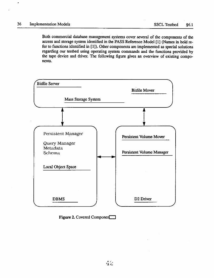
Both commercial database management systems cover several of the components of the access and storage system identified in the PASS Reference Model [l] (Names in bold refer to functions identified in [1]). Other components are implemented as special solutions regarding our testbed using operating system commands and the functions provided by the tape device and driver. The following figure gives an overview of existing components.
/ Bitfile Server ' Bitfile Mover
Mass Storage System \.. ,
•
.. .. ,
' ,
Persistent Manager Persistent Volume Mover
Query Manager Metadata Schema Persistent Volume Manager
Local Object Space
DBMS D2 Driver '- , \.. ,
Figure 2. Covered Componerc::J
"•' J
'.t.~
§6.l SSCL Testbed Implementation Models 37
6.1.1 Data Management Functionality
Either database management system provides a Persistence Manager, implementing persistence for objects e.g. tables in case of a relational DBMS. Query capabilities are provided by both systems covering the functionality of a Query Manager. The database Schema is an integral part of the DBMS's. Application specific Metadata, a catalog of information about objects and collections of objects and an Object Dictionary and a Volume Dictionary, mapping objects to storage locations are not part of the commercial products but can be implemented as application programs using the database mechanisms. The Local Object Space and the migration of objects between memory and disk is controlled by either DBMS and is transparent to the user.
The units currently managed by the for PASS at the SSC are databases of about 100 MB in size. Each database contains the complete data for approximately 100 events. Complete means all the data that is important for our applications. Currently there is no information available about the location of objects on tape, therefore several databases may have to be scanned sequentially. This requires sequential loading of the 100 MB chunks. Processing with finer granularity is done after the database becomes available to the application. A Persistent Volume Manager together with a Volume Dictionary and Object Dictionary mapping objects to volumes and scheduling loading will be implemented as part of the proposed future PASS system [2] at the SSC. This will make use of the commercial DBMS's, the units will still be 100 MB chucks of complete events.
6.1.2 Tertiary Storage
Sybase provides mechanisms to transfer databases to and from tape. Databases are identified by name, objects can be uniquely identified within a database. Special Sybase commands are used to copy databases to tape or extract them from tape. This is currently not supported for D2 tape drives. For Objectstore a modified version of the Unix filesystem commands osmv and oscp and generic tape commands are used to archive databases to tape. The user has to keep track of the location of the data as well as any meta data about the content of a database to support access to data in the mass store. The tape in the current system has to be determined and loaded by hand. A more transparent Persistent Volume Mover could be implemented based on the current commercial tape system. The functions of a Bitfile Server and Bitfile Mover as mentioned in the Pass Reference Model are not supported explicitly by the tertiary storage device. The D2 drives covers this functionality with its functions to store and retrieve data from files using standard read/ write access to tapes.
6.1.3 Parallelism
Both database management systems support concurrent access for multiple application programs to the same database as well as the possibility for a program to talk to several databases at the same time. If multiple databases are used, loading of a chunk of data can
• 1i t)
38 Implementation Models Generic Model §6.2
take place at the same time as other databases are being used. With the current configuration only one database can be loaded at a time.
6.2 Generic Model
[This still needs to be done.]
6.3 SDC/GEM Model
[This still needs to be done.]
A ·,
'i '.t

§6.3 SDC/GEM Model
Al \. .
'1 t)
Implementation Models 39
..:.
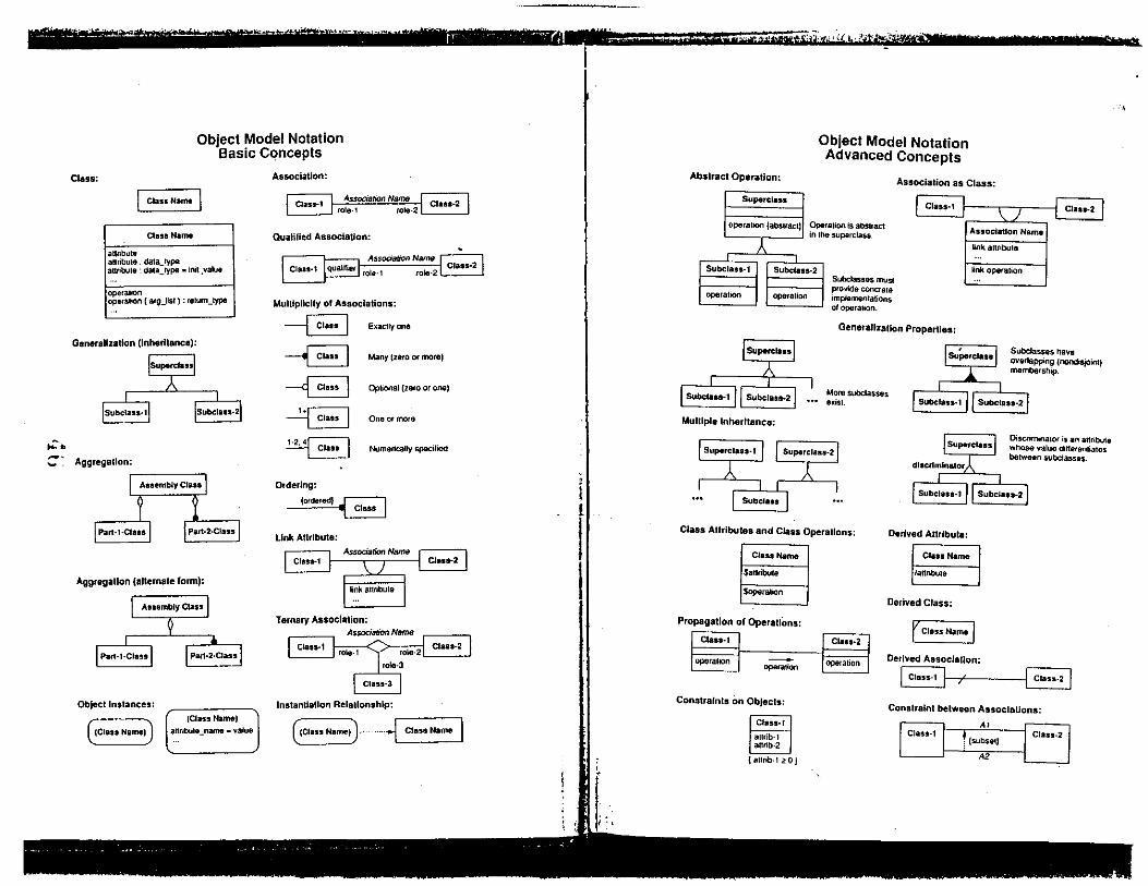
Class:
Object Model Notation Basic Concepts
I Class N•me I Class Namt
annbu1e annbute. da1a_type annbule : data_type .. ini1_value
openmon oparalion ( a1g_lisl) : retum_type
Association:
L~ AssocialiOn Name rc;n~-=-~ J __:::::_:__J rote-1 role-2 LL:°---~·
Qualified Association:
AssoaaflOll Name ,_ _ _ccce,c_cccc=~ Class-2
role·2• ~---
Mulllpllclty of Associations:
--B Exaclly Ofl8
Generalization (Inheritance):
-B ISuJ>9rclassl
Subclass·1 iSubclass-2
-<8 -~ ~
Many tzero Of more)
Opliooal (zero or one I
One or more
Numerically specified
::· Aggregallon: ~
Aggregation (alternale form):
Assembly Class
Part-l·Class
Object Instances:
{Class Name)
Parl-2.Class
(Class Name)
anr1bu1e _name • value
Ordering:
~ link Attribute:
Assodalion Name Class-1 Class-2
~nk anribute
Ternary Association: Ar;!:Odation Name
Class·1 ~ Claas-2 I rola-1 1,... rola·2~ role-3
Class-3
Instantiation RelaUonshlp:
((ClassName))· ........ Fa~e I
' t l
I
f ''
Abstract Operation:
Superclass
operallOO (absiractl
}
Subclass-1 Subclass·2
operation operalion
Superclass
Subclan-1 Subclata-2
Mulllple Inheritance:
Object Model Notation Advanced Concepts
Association as Class:
·ralion is abslract ,e superclass.
Subclasses mus1 provide concrete implementations otoperaltOn.
I Class-1 : \ / : Class-2
Association Nama
~nk anriOula
~nk operalion
Genarallzatlon Properties:
Mora subclasses exist.
' Supe1class Subclasses have overlapping (nondisjoint) membership.
Subclass-1 Subclass·2
Superclass-I Superclass-2
Oiscrimmator is an attnbute whose value ditlerenliates between subclasses.
Subclass
Class Attributes and Class Operallons:
ClastName
$allribul8
Soperalion
Propagation of OperallOns: r-cc--
\;f8SS•I
operalion -operation
Constraints on Objects:
Class· I
aurib·l attrib-2
I aurib-1 <? o J
Class·2
operation
Subclasa-1 11 Subclass-2
Derived Attribute:
Class Name
1annbu11
Derived Class:
rcla~~
Derived Association:
8-r---EJ Constraint between Associations:
Class-1 Al
t (subsetJ
A2
Class-2
.,
.. __ _;. , .
11 Methodology Summary
This chapter summarizes the methodology of the Object Modeling Technique. The tech· niques discussed in previous chapters are listed below as numbered steps. While this implies that the order is imponant, we find that:
• Experienced developers are able to combine several steps or perform cenain steps in - parallel for portions of a project.
• Iteration of the steps is necessary at successively lower levels of abstraction, adding more detail to the model.
• After the overall analysis has been completed at a high level of abstraction, subsystems within a large project can be designed independently and concurrently at lower levels of abstraction.
The distinction between analysis and design may at times seem arbitrary and confusing. The following simple rules should guide your decisions concerning the proper scope of analysis and design.
The analysis model should include information that is meaningful from a real-world perspective and should present the external view of the system. The analysis model should be understandable to the client for a system and should provide a useful basis for eliciting the true requirements for a system. The true requirements are those that are really needed, internally consistent, and feasible to achieve.
In contrast, the design model is driven by relevance to the computer implementation. Thus the design model must be reasonably efficient and practical to encode. In practice, many portions of the analysis model can often be readily implemented without change; thus there may be considerable overlap between the analysis and design models. The design model must address low level details that are elided in the analysis model. The analysis and design models combine to provide valuable documentation for a system from two different. but complementary, perspectives.
260
11.1 ANALYSIS 261
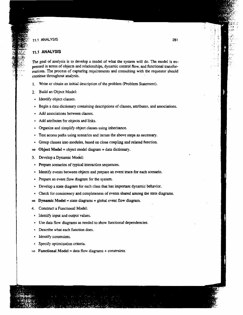
11.1 ANALYSIS
The goal of analysis is to develop a model of what the system will do. The model is expressed in terms of objects and relationships, dynamic control flow, and functional transformations. The process of capturing requirements and consulting with the requestor should continue throughout analysis.
I. Write or obtain an initial description of the problem (Problem Statement).
2. Build an Object Model:
Identify object classes.
Begin a data dictionary containing descriptions of classes, attributes, and associations.
Add associations between classes.
• Add attributes for objects and links.
Organize and simplify object classes using inheritance.
Test access paths using scenarios and iterate the above steps as necessary.
• Group classes into modules, based on close coupling and related function.
=> Object Model = object model diagram + data dictionary.
3. Develop a Dynamic Model:
Prepare scenarios of typical interaction sequences.
• Identify events between objects and prepare an event trace for each scenario.
• Prepare an event flow diagram for the system.
Develop a state diagram for each class that has important dynamic behavior.
• Check for consistency and completeness of events shared among the state diagrams.
=> Dynamic Model = state diagrams + global event flow diagram.
4. Construct a Functional Model:
Identify input and output values.
Use data flow diagrams as needed to show functional dependencies.
Describe what each function does.
Identify constraints.
Specify optimization criteria.
=> Functional Model = data flow diagrams + constraints.

';;
. - ,.-; .. ::-. ·"' :-t:::'· .
262 Chapter 11 I METHODOLOGY SUMMARY
5. Verify, iterate, and refine the three models:
• Add key operations that were discovered during preparation of the functional model to the object model. Do not show all operations during analysis as this would clutter the object model; just show the most important operations.
Verify that the classes, associations, attributes, and operations are consistent and complete at the chosen level of abstraction. Compare the three models with the problem statement and relevant domain knowledge, and test the models using scenarios.
Develop more detailed scenarios (including error conditions) as variations on the basic scenarios. Use these "what-if' scenarios to further verify the three models.
Iterate the above steps as needed to complete the analysis.
=> Analysis Document= Problem Statement + Object Model + Dynamic Model + Functional Model.
11.2 SYSTEM DESIGN
During system design, the high-level structure of the system is chosen. Chapter 9 presents several canonical architectures that may serve as a suitable starting point. The object-oriented paradigm introduces no special insights into system design, but we include system design for complete coverage of the software development process.
l. Organize the system into subsystems.
2. Identify concurrency inherent in the problem.
3. Allocate subsystems to processors and tasks.
4. Choose the basic strategy for implementing data stores in terms of data structures, files, and databases.
5. Identify global resources and determine mechanisms for controlling access to them.
6. Choose an approach to implementing software control:
Use the location within the program to hold state, or
Directly implement a state machine, or
• Use concurrent tasks.
7. Consider boundary conditions.
8. Establish trade-off priorities.
=> System Design Document= structure of basic architecture for the system as well as high level strategy decisions .

11.3 OBJECT DESIGN 263
11.3 OBJECT DESIGN
During object design we elaborate the analysis model and provide a detailed basis for implementation. We make the decisions that are necessary to realize a system without descending into the particular details of an individual language or database system. Object design starts a shift away from the real-world orientation of the analysis model towards the computer orientation required for a practical implementation.
I. Obtain operations for the object model from the other models:
Find an operation for each process in the functional model.
Define an operation for each event in the dynamic model, depending on the implementation of control.
2. Design algorithms to implement operations:
• Choose algorithms that minimize the cost of implementing operations.
• Select data strUctures appropriate to the algorithms.
Define new internal classes and operations as necessary.
• Assign responsibility for operations that are not clearly associated with a single class.
3. Optimize access paths to data:
• Add redundant associations to minimize access cost and maximize convenience.
• Rearrange the computation for greater efficiency.
Save derived values to avoid recomputation of complicated expressions.
4. Implement software control by fleshing out the approach chosen during system design.
5. Adjust class strUcture to increase inheritance:
• Rearrange and adjust classes and operations to increase inheritance.
Abstract common behavior out of groups of classes.
Use delegation to share behavior where inheritance is semantically invalid.
6. Design implementation of associations:
Analyze the traversal of associations.
• Implement each association as a distinct object or by adding object-valued attributes to one or both classes in the association.
7. Determine the exact representation of object attributes.
8. Package classes and associations into modules.
=> Design Document = Detailed Object Model + Detailed Dynamic Model + Detailed Functional Model.

..
'' :.·.
''.
264 Chapter 11 I METHODOLOGY SUMMARY
11 A CHAPTER SUMMARY
The OMT Methodology is based on the use of an object-oriented notation to describe classes and relationships throughout the life-cycle. The Object Model is augmented with a Dynamic Model and a Functional Model to describe all aspects of a system. The analysis phase consists of developing a model of what the system is supposed to do, regardless of how it is implemented. The design phase consists of optimizing, refining, and extending the Object Model, Dynamic Model, and Functional Model until they are detailed enough for implementation. As we shall see in Pan 3, implementation of the design is a straightforward matter of translating the design into code, since most difficult decisions are made during design.
EXERCISES
analysis dynamic model functional model object design
object model relationship between models system design
Figure 11.1 Key concepts for Chapter l l
Use the Object Modeling Technique to develop the following systems. Prepare scenarios, diagrams, models, specifications, and documents as appropriate. For each diagram and model that you prepare, show both your first version and your last refinement. State any assumptions you make concerning functional requirements. Also. summarize the order in which you followed. the steps of the methodology.
11.1 (Project) A simple flight simulator. Using a bit mapped display. present a perspective view from the cockpit ofa small aiiplane, periodically updated to reflect the motion of the plane. The world in which flights take place includes mountains. rivers, lakes, roads. bridges. a radio tower and, of course, a runway. Control inputs are from two joysticks. The left joystick operates the rudder and engine. The right one controls ailerons and elevator. Make the simularor as realistic as possible without being too complex .
11.2 (Project) A system for automatically executing the actions needed to build a software system from its components, similar to the UNIX Make facility. The system reads a file which describes what must be done in the fonn of dependency rules. Each rule has one or more targets, one or more sources. and an optional action. Targets and sources are names of files. If any of the sources of a rule are newer than any of its targets, the action of the rule is executed by the system to rebuild the targets from the sources.
11.3 (Project) A computer tic-tac-toe player. Inputs and outputs are provided through a dedicated hardware interface. The user indicates moves by pressing membrane switches, one for each of the nine squares. X's and O's are displayed by a liquid crystal display. The user may select a level of skill and who is to go first.
·~

Module: GEM Sheet: 1: Simulation Processes Panel: {0,0) Time: Tue Aug 17 09:36:39 1993
Simulation Processes
imulatedlnteractionSource imulatedlnteractionSource imulatedlnteractionSource
SimulatedEventBuilder SimulatedEventBuilder
GeometryBuilder imuilatedPipelineBuilde
GeometryTranslator')-----+(.Transport
'--~ CalorimeterHits
alorimeterDigitization eve.11 Digitization
Level3Filter

Module: GEM Sheet: 2: Raw Data Processes Panel: (0,0) Time: Tue Aug 17 09:36:39 1993
Raw Data Processes
Calorlmeterlevel1 Muonlevel1 Trackerlevel1
TrackerDAQ CalorimeterDAQ MuonDAQ Level1 Filter
Level3Filter
--· 0 ,-,

Module: GEM Sheet: 3: Reconstruction Processes Panel: (O,O) Time: Tue Aug 17 09:36:39 1993
Reconstruction Processes
Leve13Filter
rackerPatternRecognltlon alortmeterPatternRecognition uonPatternRecognition
TrackerFitting CaiorimeterFittin
EventStore

Module: GEM Sheet: 4: Analysis Processes Panel: (0,0) Time: Tue Aug 17 09:36:39 1993
Analysis Processes
User Analysis EventDlsplay
G ~-•
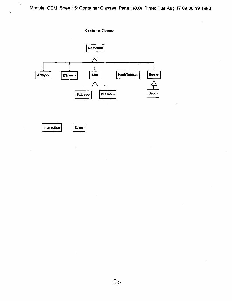
Module: GEM Sheet: 5: Container Classes Panel: (0,0) Time: Tue Aug 17 09:36:39 1993
Container Classes
Container
Array<> BTree<> Hash Table<>
Sllisl<> Ollis!<> Set<>
I interaction I
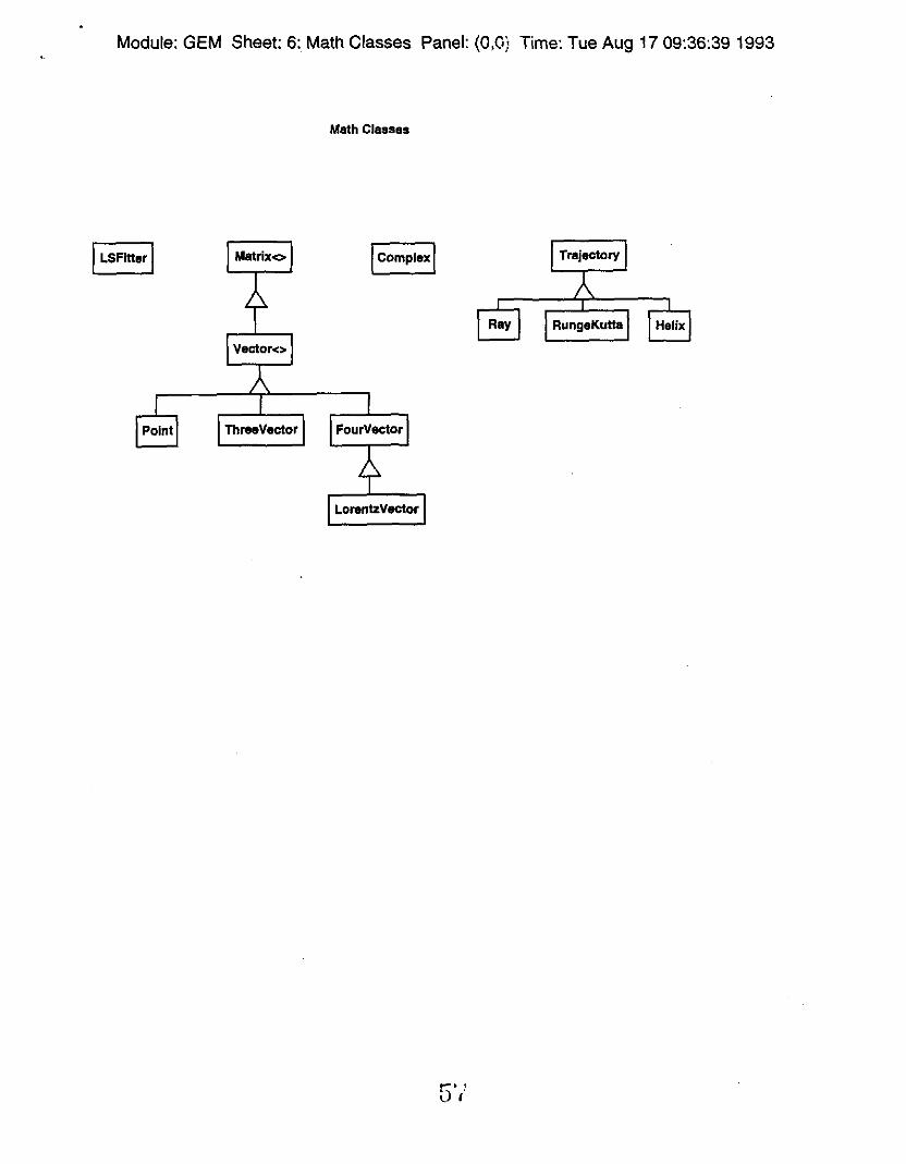
Module: GEM Sheet: 6: Math Classes Panel: (0,0) Time: Tue Aug 17 09:36:39 1993
Math Classes
Matrix<> Trajectory
Ray RungeKutte Helix
Point Three Vactor
LorantzVactor
.... ' iJ i

Module: GEM Sheet: 7: Particle Classes Panel: (C,O) Tims: Tue Aug 17 09:36:39 1993
Particle Classes
Particle
ldentlfledPartlcie MCPartlcle
Gamma Electron Muon Jet Neutrino
Sb
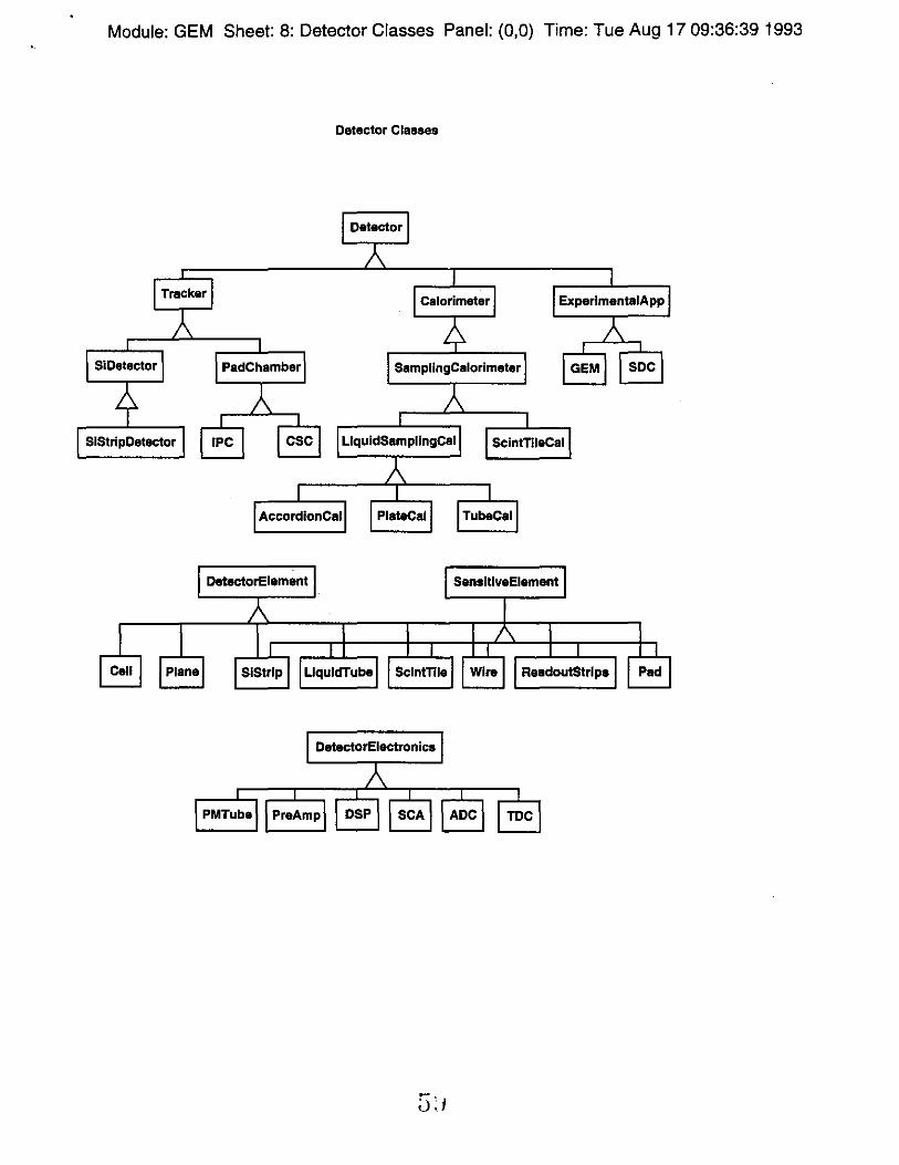
Module: GEM Sheet: 8: Detector Classes Panel: (0,0) Time: Tue Aug 17 09:36:39 1993
Detector Classes
Detector
Tracker ExperlmentalApp
Si Detector SamplingCalorimeter GEM soc
SIStripDetector IPC csc LlquidSampllngCal ScintTlleCal
AccordlonCal PlateCal TubaCal
DetectorElamant SansitlvaElamant
Call Plana Sclntnla RaadoutStrlps
DatectorElectronlcs
SCA TDC
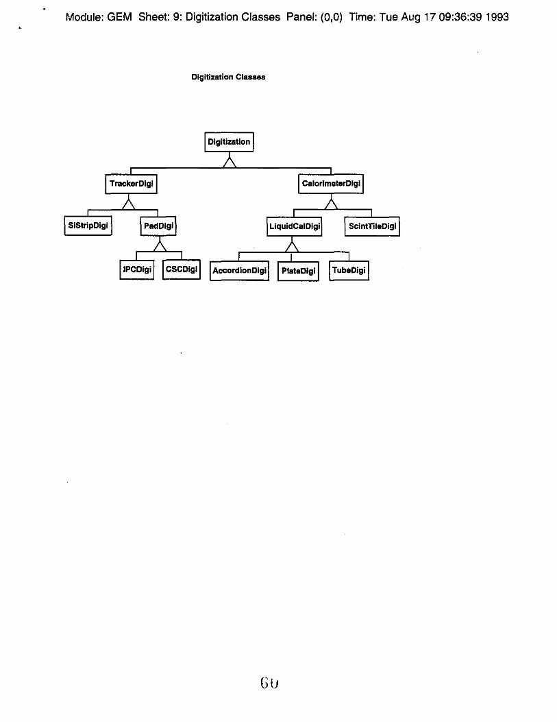
Module: GEM Sheet: 9: Digitization Classes Panel: (0,0) Time: Tue Aug 17 09:36:39 1993
Digitization Classes
Digitization
TrackerDlgl CalorimeterDlgi
SIStripDigl PadDlgl SclntTileDigi
IPCDlgi CSCDlgl AccordlonDlgl PlateDlgl TubeDlgi
Gu
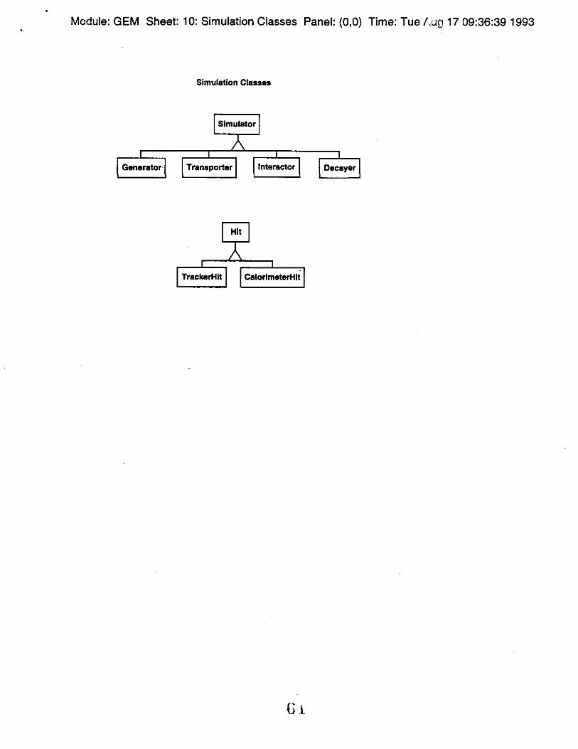
Module: GEM Sheet: 10: Simulation Classes Panel: (O,O) Time: Tue /.uc 17 09:36:39 1993
Simulation Classes
Simulator
Generator Transporter lnteractor Decayer
Hit
TrackerHlt CalorlmeterHlt
Gt

Module: GEM Sheet: 11: Reconstruction Classes Panel: (0,0) Time: i"ue Aug 17 09:36:39 1993
Reconstruction Classes
Reconstructor
TrackFindar ClusterFlnder TrackFittar Vertex Fitter
VertexFinder PartlcleFlnder KlnematlcFitter
ElectronFinder GammaFinder Muon Finder
JetFlnder NautrlnoFlndar
RacoObj
Vertex Bump Cluster
MCTrack Raco Track MC Vertex Raco Vertex
I' , . U<::.

Module: GEM Sheet: 12: Analysis Classes Panel: (O,O) Time: Tue Au';j 17 09:36:39 1993
Analysis Classes
Histogram I Accumulator I
Hlst1D Hlst2D

Module: GEM Sheet: 13: Other Classes Panel: (0,0) Time: Tue AuQ 1 ". 09:36:39 1993
Other Classes
CallbratlonConstant Identifier I TimeStamp I
Application Server Organization:
a proposal from Mark Selover and JH
Background:
o The app. server "project" is:
- putting software of use to several people into a common area, thereby making more effective use of human and material resources (cf. ASIS project from CERN)
- afs has been found to be a convenient way to achieve this goal. There are ACL's, a global name file-name space, file-level caching
- The GEM tree, and alot of other software (230 binaries for the SUN) are installed in this area
- BUT we (the SSC lab) has had no coherent strategy for populating and maintaining products. In fact, there is no real "project" and definitely no project leader
John Hllgart - SSC Lab August 17, 1993 Page 1
•
app. server project is, cont.
- Friday afternoon some IS, GEM, and SOC reps met and agreed on:
A) afs must be stress-tested to anticipate scaling problems, and monitored, like PDSF, to determine
usage patterns, etc. IS agreed to do this.
B) A scheme for documentation of the products, including support disclaimer, name of a responsible
will be provided by IS for areas under their control.
There was disagreement on the organizational principles guiding the choice of directory names.
As GEM software librarian, I SHALL FIND A SOLUTION TO THE ABOVE PROBLEM, WHICH WILL NOT GO AWAY BY ITSELF!
The latest proposal attacks the high-level organzation problem.
John Hllgart - SSC Lab August 17, 1993 Page 2

•
MS, JH proposal: what comes under /usr/ssc
Currently, we have _ orgs
- -----/us r / s s c / {physics, g erTI,; d~:,pub,build,is,prod}, i.e., a mixture of organiztions and other stuff
The proposal:
/usr/ssc/{pr ,is,gem,sdc,doc, pu b,prod}
o pr subsumes "physics", and becomes the landing pad for:
- packages which know something about physics - packages written or co-written by someone in prd,
GEM, or SOC - packages for which only pr users are foreseen
o "pub" is reserved for use-at-your-own-risk public domain shareware which has not been written by someone at the SSC
o "prod" remains for commercial software
John Hllgart - SSC Lab August 17, 1993 Page 3
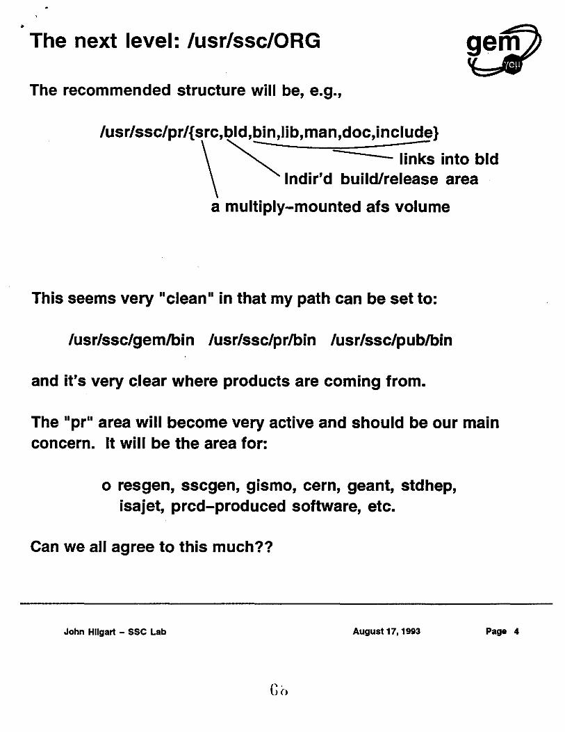
• The next level: /usr/ssc/ORG
The recommended structure will be, e.g.,
/usr/ssc/pr/{src,bld,bin,lib,man,doc,include}
~ links into bid lndir'd build/release area
a multiply-mounted afs volume
This seems very "clean" in that my path can be set to:
/usr/ssc/gem/bin /usr/ssc/pr/bin /usr/ssc/pub/bin
and it's very clear where products are coming from.
The "pr" area will become very active and should be our main concern. It will be the area for:
o resgen, sscgen, gismo, cern, geant, stdhep, isajet, prcd-produced software, etc.
Can we all agree to this much??
John Hllgart - SSC Lab August 17, 1993 Page 4
•
So Where do you put Interviews?
ans: Somewhere in /usr/ssc/pub, but we don't address this issue in the above proposal.
ans 2: I think the question is secondary (and yes, I will suggest a certain place if asked) to the overall design considerations addressed above.
John Hllgart - SSC Lab August 17, 1993 Paga 5

•
SSC EPICS System. (Global control system prototype).
* The system arrived last week and has been installed next to the TIR
* The system consists of a Sun Spare IPX station, some hardware to control (power supply, stepper motor, .... ), the EPICS software (and a demo package) and a pile of manuals.
* Those of you interested in working with EPICS should contact me for an account on ssc-epics, a demo and a copy of the "introduction to Epics" by Bill Kornke.
*Warnings:
1. There are a few minor problems with the setup itself, not everything in the intro. works as it should work. Bill Kornke and I are working on this.
2. At present, everybody can overwrite almost everything. I'm trying to fix that. In the meantime: do not save any modified files unless the text explicitly tells you to do so.
3. No backups are being made, the system is not yet connected to the network. Both problems will be solved soon.
* We had a hardware problem last week that made the screen look like a 1V. with a bad antenna. It disappeared for no apparent reason. Should this problem ever occur while you are working on the system, call me immediately.
Henk Uijterwaal GEM/SSCL
[email protected] 1-214-708-6192
7U
August 17, 1993 Pa e 1