local distributor - cotswold valves · local distributor assistance: our experienced and fully...
TRANSCRIPT

700SeriesS a f e t y R e l i e f
V a l v e s
P l e a s e c o m p l e t e t h e f o l l ow i n g
Name:
Position:
Company:
Address:
Post Code:
Tel No:
Fax No:
Email:
Simply photocopy andfax to us for moreinformation on. . .
P l e a s e t i c k b o xw h e r e a p p r o p r i a t e
Associated Products
Standard Safety Relief Valves
Direct Acting Pressure Reducing Valves
Marvac Pressure/Vacuum Valves
Marston Bursting Discs & Explosion Vent Panels
Amal Flame Arresters
Birkett API/ASME Spring & Pilot SRV’s
G4 Pilot Operated Pressure Reducing Valves
L O C A L D I S T R I B U TO R
Assistance:
Our experienced and fully trained team of Technical Sales Engineers and
distributors are available to give advice and assistance on the sizing and
selection of the Bailey 700 Series and any other associated products.
This service is available to you by calling your local distributor or our
Bailey Technical Sales Department, who will be happy to help.
Details of our worldwide network of distributors and regional offices
are available on our website.
BA700702 Registered Office: Sharp Street,Worsley,Manchester M28 3NA, UK.

Con
tent
s
Application Medium 700 Series Safety Relief Valve
Vented boilers Hot Water 706Un-vented boilers 716
746/766
Boiler, pipeline and Steam 706/716vessel protection 746
756/766
Compressor pipeline Air 706and receiver protection 716
746
Pipeline and vessel Cold Water 706protection 716
746
Process pipeline Process/Corrosive Liquids 716 Stainless steeland vessel protection 746 Stainless steel
Clean steam and Steam and Gases 716 Stainless steelhygienic environments 746 Stainless steel
Pipework, tank and Cryogenic Gases 776equipment protection
Pipework, tank and Cold & Fine Gases 716equipment protection 776
APPLICATIONS TABLE - 700 SERIES
The selection of 700 Series figure number for each application depends on:Pressure - capacity - material - temperature - fluid - connection required.
C O N T E N T SPage No.
Definitions 2 – 3
Valve Information and Numbering Systems 4 – 10
Installation 11
Dimensions 12 – 13
Air Capacity Table 14 – 15
Steam Capacity Table 16 – 17
Water Capacity Table 18 – 19
Hot Water Capacity Table 20 – 21
706/716 Spring Selection 22 – 23
Technical Specification 241
Bailey’s design service can help to specify the
most appropriate size and type of valve for any
specific application, with the ability to include
special modifications where necessary.
700 SeriesS a f e t y R e l i e f V a l v e s
The Bailey 700 Series of Safety Relief Valves
offers a broad spectrum of protection against
over-pressure for vital services such as steam,
air, gases, water and process fluids. The 700
Series Safety Relief Valves offer full protection,
with maximum discharge capacity provided by
features such as full lift, top guided construction
and unobstructed seat bore. No matter what
the application, all valves are designed for leak-
free operation thanks to the choice
of various seating materials.
Global legislation, covering all
pressure equipment and systems,
requires regular inspection of plant,
pipework and safety provisions.
Bailey Safety Relief
Valves have
demonstrated proven
reliability over many years
and require minimal
maintenance.
THE LOGICAL CHOICE
Experience and focus on customer service
make Bailey the logical choice of supplier for
safety valves to protect pipework, boilers and
vessels - across a wide range of applications. A
policy of continuous improvement ensures that
Bailey valves will always meet current legislative
requirements and of course provide exceptional
reliability and performance.
By choosing Bailey Safety Relief Valves, you are
selecting availability, quality, professional advice
and proven performance - all delivered through
an extensive worldwide network of
distributors. Should a valve
change-out be required at short notice,
ex-stock availability of most standard valves
ensures minimal plant downtime and
maximum protection.
700 SeriesT h e c o m p l e t e s o l u t i o nw i t h g l o b a l s u p p o r t

Popping Pressure
The pressure at which the valve disc rapidly movesfrom a slightly open (simmer) position to apractically full open position.
Superimposed Back Pressure
Pressure higher than atmosphere in the safety valveoutlet. This may result from discharge into thecommon disposal system of other safety valves ordevices, or as a result of a specific designrequirement. Back pressure can be either constantor variable depending on the operating conditions.
Built Up Back Pressure
The pressure existing at the outlet of a safety valvecaused by flow through the valve into the disposalsystem.
Differential Set Pressure
This is the difference between the set pressure andthe constant superimposed back pressure. It isapplicable only when a conventional type safetyrelief valve is used to discharge against constantsuperimposed back pressure. (It is the pressure atwhich the safety valve is set at on the test benchwithout back pressure.)
BS 6759 TOLERANCES FOR 700 SERIES SAFETY RELIEF VALVES
PART % Overpressure % Blowdown Medium
Part 1 5% on 716/746/756/766 *0.3 Barg or 5% on 756 Steam and Hot Water10% on 706 or 10% on 766 100°C or Above
*0.3 Barg or 15% on 706/716/746
Part 1 5% on 716/746/756/766R *0.6 Barg or 20% on Hot Water Below10% on 706 706/716/746/756/766R 100°C
Part 2 10% *0.3 Barg or 10% on Compressed Air and706/716/746 706/716/746 Inert Gases
Part 3 10% on 15% on Gases706/716/746 706/716/746
Part 3 10% *0.6 Barg or 20% on Liquids706/716/746 706/716/746
AD MERKBLATT
A2 (TUV) 10% on 776 10% on 776 Air and Gases
A2 (TUV) 5% on 746 10% on 746 Steam, Air and Gases
D E F I N I T I O N S
Cold Differential Set Pressure
The pressure at which a safety relief valve, intendedfor high temperature service, is set on a test rigusing a test fluid at ambient temperature. The colddifferential test pressure will be higher than the setpressure, in order to compensate for the effect ofelevated temperature on the valve.
Valve Lift
The actual travel of the valve disc away from theseat when the valve is relieving.
Discharge Capacity
Actual rate of discharge of service media, which canbe expressed in mass flow or volumetric terms.
Equivalent Capacity
Calculated mass or volumetric flow rate of thevalve of a given test fluid. The fluids commonlyused for test purposes are steam, air and water.
3*Whichever is the greater.
Defi
nitio
ns
110
100
90
Accumulation Over-pressure(Typical)
Blowdown(Typical)
% of VesselDesign Pressure
Pressure VesselRequirement
Safety ValveCharacteristic
SetPressure
DesignPressure
Re-seatPressure
MaximumPermitted
Accumulation
MaximumRelievingPressureDefi
nitio
nsSafety Valve
A valve which automatically discharges gases andvapours so as to prevent a predetermined safepressure being exceeded. It is characterised by arapid full opening action and is used for steam,gases or vapour service.
Relief Valve
A valve which automatically discharges fluid, usuallyliquid, when a predetermined upstream pressure isexceeded.The term is commonly used for pressurerelieving valves in which the lift is proportional tothe increase in pressure above the set pressure.
Safety Relief Valve
A valve which will automatically discharge gases,vapours or liquids, to prevent a predetermined safepressure being exceeded. It is characterised by arapid opening action.
Accumulation
The pressure increase over a maximum safeworking pressure of the vessel or system when thesafety relief valve is discharging at its rated capacityis called accumulation.The term refers to thevessel or system to be protected and not to thevalve. Accumulation is the same as over-pressurewhen the valve is set at the design pressure of thevessel.
PRESSURE TERM RELATIONSHIP
Note: System operating pressure must always be less thanre-seat pressure.
Set Pressure
The pressure measured at the valve inlet at whicha safety relief valve should commence to liftunder service conditions.
Overpressure
The pressure increase above set pressure at thevalve inlet at which the discharge capacity isattained. Usually expressed as a percentage of setpressure.
Re-Seat Pressure
The pressure measured at the valve inlet at whichthe safety relief valve closes.
Blow-Down
The difference between the set pressure and there-seating pressure expressed as a percentage ofthe set pressure or as a pressure difference.
Simmer
The pressure zone between the valve setpressure and the popping pressure. In thispressure zone the valve is only slightly open andtherefore discharging a small percentage of itsrated capacity.
D E F I N I T I O N S
2

716
716
FIGURE NUMBERING SYSTEM
10
13
1416
8
6
1
7
9
11
4
15
5
12
3
16
2
716
The 716 Safety Relief Valve combines a top guided,unobstructed seat bore with full lift capability to providemaximum discharge capability.
Positive reseating is achieved with freely pivoting EPDMdiscs for gas, hot water and other liquid duties up to150°C. Optional Aflas soft seats increase the range to200°C. Precision lapped stainless steel trim gives positivere-seating for steam duty up to 230°C. Fitted with a testlever for inline safety checking, or alternatively with asealed dome for service conditions requiring a pressuretight seal on the discharge side, eg. liquid service.
The body material is available in cast bronze, iron andstainless steel, ranging from DN15 to DN50 in size.
D E S I G N
F E AT U R E S A N D B E N E F I T S
• Certified to BS6759 parts 1, 2 and 3 bySAFED/AOTC.
• Full lift discharge capacity.
• Top un-wetted guiding giving unobstructed seat bore.
• Each valve individually tested.
• Positive re-seating with either resilient or stainlesssteel trim.
• Discharge capacity at 5% overpressure on steam duty.
• Low stress springs to BS6759.
CONNECTIONS
Screwedin and out(Inlet availableMale or Female)
Flanged inscrewed out
Flangedin and out
CAP
DPressuretightdome
LOpenlever
CODE TRIM BODY
AS St. steelSt. steelBS Aflas
ES EPDMVS Aflas BronzeSS St. steel
AF St. steel St. steelBF Aflas
EF EPDMVF Aflas BronzeSF St. steel
CF EPDMDF Aflas Cast ironFF St Steel
ITEM PART MATERIALCast Iron St.St. Bronze
1 Body Cast Iron St.St Bronze2 Seat St.St St.St Bronze3* Disc Various Various Various4 Spindle Brass St.St Brass5 Guide Bronze Nickel Bronze
alloy6 Top Spring Brass St.St Brass
Cap7* Spring Chrome St.St Chrome
vanadium vanadium8 Adjusting Brass St.St Brass
Screw9 Lock Nut Brass St.St Brass10† Dome Nylon St.St Nylon11 Lever Bronze N/A Brass12* Ball St.St Monel St.St13 Padlock Brass N/A Brass14 Bush PTFE PTFE PTFE15 Bottom Brass St.St Brass
Spring Cap16 Pinning Steel St.St Brass
Screw
Note:* Recommended spares.† Synthetic dome should not be adjacent to externalheat sources.Flange options: BS10 Table E, F and H, BS4504, PN16/25and ANSI 150.
Certified Drawings are available with material parts list.
5
CE MARKING
This range of Safety Relief Valves has been certifiedto the requirements of the PED. Set pressuresbelow 0.5 Barg do not require certification, hencecannot be CE marked.
706
9
10
12
8
7
4
1
13
146
5
11
3
14
2
706
The 706 Safety Relief Valve is designed to take fulladvantage of its high lift capability by incorporatingtop guiding, which provides an unobstructed seatbore.
Positive reseating is achieved by a freely pivotingEPDM disc in the standard valve, for potable waterduties up to 95°C. The Aflas trim is suitable for air,gas, vapour, or liquid duties up to 200°C whileproviding greater resistance to chemical attack. Themetal disc option is primarily designed for use onhigh temperature duties above 200°C. Fitted with atest lever for inline safety checking, or alternativelywith a sealed dome for service conditions requiringa pressure tight seal on the discharge side, eg. liquidservice with enclosed discharge.
The body material is cast bronze ranging fromDN15 to DN50 in size.
D E S I G N
F E AT U R E S A N D B E N E F I T S
FIGURE NUMBERING SYSTEMCE MARKING
TRIM
E EPDM
V Viton
M Metal
• Certified to BS6759 parts 1, 2 and 3 bySAFED/AOTC.
• High Lift, high coefficient flow capability.
• Top un-wetted guiding giving unobstructed seat bore.
• Each valve individually tested and set.
• Water Research Council (WRC) listed(certificate no. 9404007).
• Positive re-seating with either resilient or metaltrims.
• Low stress springs to BS6759.
706
CONNECTIONS
SScrewedin and out(Inlet availableMale or Female)
FFlanged inscrewed out
CAP
DPressuretight dome
LOpen lever
ITEM PART MATERIAL
1 Body Bronze2 Seat Bronze3* Disc Various4 Spindle Brass5 Spring Cap Brass6* Spring Chrome vanadium7 Adjusting Screw Bronze8 Locking Ring Bronze9† Dome Nylon10 Lever Bronze11* Ball Stainless Steel12 Padlock Brass13 Bush PTFE14 Pinning Screw Steel
Note:* Recommended spares.† Synthetic dome should not be adjacent to externalheat sources.Flange options: BS10 Table E and F, BS4504 PN16/25 andANSI 150.
Certified Drawings are available with material parts list.
4
This range of Safety Relief Valves has been certifiedto the requirements of the PED. Set pressuresbelow 0.5 Barg do not require certification, hencecannot be CE marked.

756
11615
22211712132311426328303229
41
424237985201812102511
756
The 756 Safety Valve combines a top piston guidedvalve and an unobstructed seat bore with a full liftcapability, giving maximum discharge capacity. Thedesign incorporates an adjustable blowdown ringand meets all the requirements of BS6759 Part 1.
A freely pivoting disc and precision lapped stainlesssteel trim gives positive reseating for steam duty.Fitted with test lever for inline testing. Ideallysuited to applications on steam boilers andpipelines where blowdown tolerances are critical.
Body material is available in carbon steel, rangingfrom DN25 to DN80 in size.
D E S I G N F E AT U R E S A N D B E N E F I T S
• Certified to BS6759 Part 1 by SAFED/AOTC.
• Full Lift discharge capacity.
• Top un-wetted guiding giving unobstructed seat bore.
• Adjustable blowdown, to 5%.
• Each valve individually tested and set.
• All valves fitted with test lever and padlock.
• Precision lapped stainless steel trim.
• Low stress springs to BS6759.
• Discharge capacity at 5% overpressure.
• Piston design allows back pressure up to 50%.
ITEM PART MATERIALCarbon Steel
1 Body Carbon Steel2 Bonnet Cast Iron3 Cap Cast Iron4 Seat St.St.5* Disc St.St.7* Set Screw Gasket NAF8 Blowdown Ring St.St.9 Setting Screw Brass10 Guide Plate Bronze11 Spindle St.St.12 Spring Plate Brass13 Adjusting Screw Brass14 Locknut Brass15 Body Stud Carbon Steel16 Body Nut Carbon Steel17* Spring Chrome Vanadium18* Body/Bonnet Gasket NAF20* Ball St.St.21 Nameplate St.St.22 Nameplate Pin Steel23 Drain Plug Steel24 Seat Pin St.St.25* Split Collar St.St.26 Adjusting Screw Bush PTFE28 Fulcrum Pin St.St.29 Spindle nut Brass30 Easing Lever Carbon Steel31 Grub Screw St.St.32 Spindle Washer St.St.41 Warranty Seal Lead
Note:* Recommended spares.Flange options: See page 10.
Certified Drawings are available with material parts list.
7
See Page 10 For Figure Numbering System.
There are twovent holes toensure springchamber is atatmosphericpressure.
CE MARKING
This range of Safety Relief Valves has been certifiedto the requirements of the PED. Set pressuresbelow 0.5 Barg do not require certification, hencecannot be CE marked.
746
773
132812
11
3433
22
116918
199
27
54
31
2
41
10
47
23
81
42
62
1
746
The 746 Safety Relief Valve incorporates a freelypivoting disc, which ensures correct alignment withthe nozzle. The combination of top guiding,unobstructed seat bore and full lift capability ensuresthe highest possible discharge rate thus maximumplant protection. Body material is available in caststeel and stainless steel.
The 746 safety relief valve is available in bothconventional and balanced bellows types, andfeatures a special disc style for liquid application,ensuring trouble free performance.
The ‘conventional’ arrangement is suitable forapplications where the built up pressure will notexceed 10%. The conventional valve can also beused in systems where the superimposedbackpressure is at a constant level (up to 80%).
The ‘balanced bellows’ arrangement is forapplications where several safety relief valvesdischarge into a common discharge manifold, or inany circumstances where a variable back pressurecan occur, up to a maximum of 40%.
Valve size ranges from DN25 to DN100.
D E S I G N
F E AT U R E S A N D B E N E F I T S
• Certified to BS6759 parts 1, 2 and 3 bySAFED/AOTC.
• A.D.Merkblatt A2 (TUV Approval).
• ASME Code Section VIII. (National Board Approval).
• Stoomwezen rules A1301.
• Australian standard AS1271.
• Full lift maximum discharge capability.
• Each valve individually tested and set.
• Top un-wetted guiding giving unobstructed seat bore.
• Positive re-seating with either resilient or stainlesssteel trim.
• Comprehensive range of accessories.
• Precision lapped stainless steel trim.
• Discharge capacity at 5% overpressure on steamduty.
• Low stress springs to BS6759.
See Page 10 For Figure Numbering System.
ITEM PART MATERIALSCarbon Steel St.St
1 Body Carbon St St.St2 Bonnet SG Iron St.St3 Cap SG Iron St.St4 Seat St.St St.St5* Disc# St.St St.St9 Guide Plate St.St St.St10 (H) Spindle St.St St.St11 Spring Plate St.St St.St12 Adjusting St.St St.St
screw13 Locknut St.St St.St18 (H) Body Stud Carbon St St.St19 Body Nut Carbon St St.St22 (H) Spring** C.V St.St23 (B)* Bellows Unit St.St St.St27* Body/Bonnet Garlock Garlock
Gasket28* Cap Gasket Garlock Garlock31* Ball St.St St.St33 Nameplate St.St St.St34 Nameplate Carbon St St.St
Pin41 Warranty Lead/wire Lead/wire
Seal42 Drain Plug Carbon St St.St47(BH) Spacing Piece St.St St.St62 Seat Pin St.St St.St69 Split Collar St.St St.St77 Adjusting PTFE PTFE
Screw Bush81(B) Lift Stop St.St St.St
Note:B - Denotes used on Bellows type valves.H - High Pressure type valves; and spacer and larger studs,spring and spindle.# Resilient trims are available.* Recommended spares.** Other spring material options are available dependenton duty.Flange options: See page 10.Certified Drawings are available with material parts list.
6
Lever versionsare available
CE MARKING
This range of Safety Relief Valves has been certifiedto the requirements of the PED. Set pressuresbelow 0.5 Barg do not require certification, hencecannot be CE marked.

776
21517345
1368
79110
1116121814
776
The 776 Safety Relief Valve is designed forcryogenic duty down to -196°C. The valvecombines a full lift design and top guidedconstruction with an unobstructed seat bore toprovide maximum discharge capacity. Positivesealing is achieved through a freely pivoted discwith Kel F (PCTFE) soft seat technology.
Body material is available in bronze ranging fromDN15 to DN50 in size.
D E S I G N
F E AT U R E S A N D B E N E F I T S
• The valve is designed to conform with ISO4126,AD Merkblatt A2 and BS6759 Parts 2 and 3.
• The valve is certified by TUV, with flow rates anddischarge coefficients certified in accordance withAD Merkblatt A2.
• The valve can be supplied certified toASME VIII Div 1. Details available on request.
• Production assembly and tests are carried out inaccordance with both BOC and Air Productsspecifications.
• Low stress springs to BS6759.
BOC specification: 1819660 and 399856.
Air Products specification: PSD A03, PSD JI9, andEOM 1-1-71-21M.
* Other threaded options are also available.
ITEM PART MATERIAL
1 Body Bronze2 Seat Bronze3 Valve Skirt Brass4* Valve Disc Kel F PTFE5* Valve Disc Holder Monel K5006 Guide Bronze7 Lower Spring Plate Brass8 Spindle Brass9* Spring St.St10 Upper Spring Plate Brass11 Adjusting Screw Brass12 Locknut Brass13* Ball Monel K50014 Cap Brass15* Body Gasket Gylon PTFE16* Cap Gasket Gylon PTFE17 Grubscrew St.St18 Bush PTFE
Note:* Recommended spares.
Certified Drawings are available with material parts list.
9
FIGURE NUMBERING SYSTEM
Fig. Size Trim Connections
776/1 DN15 x 20776/2M DN15 x 25776/2R DN20 x 25776/2 DN20 x 25 Soft Seat *Screwed776/3 DN20 x 32 Kel F BSP776/2M1 DN25 x 25776/4 DN25 x 32 (PCTFE) Male x776/5 DN32 x 40 Female776/6 DN40 x 50776/7 DN50 x 65
CE MARKING
This range of Safety Relief Valves has been certifiedto the requirements of the PED. Set pressuresbelow 0.5 Barg do not require certification, hencecannot be CE marked.
766
1589420
1036
1121
721213
1514
17
30
16
1825
22
28
29
26
27
23
766
The 766 Safety Valve is a double spring high lift valvewith high discharge capacity. The top guided pistondesign incorporates an adjustable blowdown ringand meets all the requirements of BS6759 Part 1.
A freely pivoting disc and precision lapped stainlesssteel trim gives positive re-seating for steam duty.Fitted with test lever for inline testing. Ideally suitedto applications on steam boilers and pipelines whereblowdown tolerances are critical.
Body material is available in cast iron and steel,ranging from DN40 to DN80 in size.
D E S I G N
F E AT U R E S A N D B E N E F I T S
• Certified to BS6759 Part 1 by SAFED/AOTC.• Top un-wetted guiding giving unobstructed seat bore.• Adjustable blowdown, to 5%.• Each valve individually tested and set.• All valves fitted with test lever and padlock.• Precision lapped stainless steel trim.• Available with resilient seats for hot water
applications. (766 Resilient)• Low stress springs to BS6759.• Piston design, metal seat valves only, allows back
pressure up to 50%.
ITEM PART MATERIAL
1 Body** Cast Iron orCarbon Steel
2 Cover Cast Iron3 Valve Disc Holder Bronze4* Valve Disc St.St.5 Seat Ring St.St.6 Guide Bronze7 Spindle St.St8 Blow Down Ring St.St9 Setting Screw St.St10* Valve Disc Ball St.St11* Spindle Ball St.St12* Spring Chrome Vanadium13 Easing Lever SG Iron14 Dome Bronze15 Dome Cap Grey Iron16 Adjusting Screw Brass17 Locknut Brass18 Spring plate Plated Steel20* Disc Retaining Clip St.St21* Body Gasket Garlock22 Locking Pin Brass23 Seat Securing Pin St.St25 Padlock Brass26 Body Stud Steel27 Body Stud Nut Steel28 Nameplate St.St29 Nameplate screw Steel30 Locknut Steel
Note:* Recommended spares.** The only difference between both options is Item 1 thebody.Flange options: See page 10.
Certified Drawings are available with material parts list.See Page 10 For Figure Numbering System.
8
There are twovent holes toensure springchamber is atatmosphericpressure.
CE MARKING
This range of Safety Relief Valves has been certifiedto the requirements of the PED. Set pressuresbelow 0.5 Barg do not require certification, hencecannot be CE marked.

Inst
alla
tion
Safety Relief Valves should always be installed in anupright position with their spring chamber vertical. Allpacking materials should be removed from the valveconnections prior to installation.
Pressure Vessels
When fitting a Safety Relief Valve onto pressurevessels, the inlet connection pipe should be as short aspossible and the bore should be at least equivalent tothe nominal bore size of the valve.
The pressure drop between the vessel and the valveshould be no more than 3% at rated capacity.
A pressure-tight dome should be specified when:
1) A backpressure must be contained within therelieving system.
2) A head of liquid is built up within the valve bodyand consequently needs to be contained.
3) The relieving medium is toxic, corrosive orenvironmentally unfriendly.
Pipelines
When fitting a Safety Relief Valve into a pipeline, theinlet connecting pipe leading from the main pipeline tothe Safety Relief Valve should be as short as possible,so that the inlet pressure drop is no more than 3% ofrated capacity.
In addition, it is advised that the Safety Relief Valve isplaced a sufficient distance downstream of thepressure source. This will protect the valve from theadverse effects of pressure pulsations.
Discharge Pipelines
These should be equal to or larger than the valveoutlet, with adequate supports, minimum number ofbends and overall length. Unless balanced bellowsvalves are installed, the maximum built upbackpressure should not exceed 10% of the setpressure, although the 746, 756 and the 766 canhandle higher back pressure if required. Steam servicevalves should be adequately drained. Alignment of the
discharge or drain should present no risk to personsor property. Protection from the collection ofrainwater or condensation in the discharge pipe isadvisable.
System Cleansing
It is essential that new installations are fully flushedand all debris removed prior to installing the valve asserious damage can be caused to valve seats, resultingin subsequent leakage.
Pressure Adjustment
Every valve is fitted with a suitable spring and testedbefore leaving the factory. Valves can be preset onrequest but to alter the set pressure, the adjustingscrew, when viewed from the top, should be screweddownwards in a clockwise direction to increase theset pressure and upwards in an anti-clockwisedirection to decrease it. Set pressure adjustmentmust be carried out by experienced and approvedpersonnel. Any change in set pressure must be withinthe range of the existing spring, if it exceeds therange, a new spring will be required. The cap lead sealmust be re-made after any adjustment to the setpressure.
Blow-down Adjustment (756 & 766 valves only)
The blow-down ring (part no. 8) is set before thevalve leaves the factory and normally no furtheradjustment will be necessary. However, if thereseating pressure has to be altered in service, theblow-down ring should be screwed (downwards)clockwise to raise the re-seat pressure, lower thepopping and simmer pressure; if the blowdown ring isscrewed (upwards) anti-clockwise the re-set pressurewill lower and the popping and simmer pressures willrise. When re-inserting the setting screw (part no 9.)it should always be placed to engage a slot in theblow-down ring. The standard blow-down is 5% for756 and 10% for 766 (minimum 0.3 barg). Forrecommended settings, please contact our technicalsales office who will be pleased to help.
I N S TA L L AT I O N
C O L D D I F F E R E N T I A L T E S T P R E S S U R E
11
When setting a valve intended for use at hightemperature on a test rig using a test fluid at ambienttemperatures, it is necessary to set the valve at aslightly higher pressure, so that it will open at thecorrect set pressure under operating conditions. Thenecessary allowance is shown in the following table.
Operating % Increase in settemperature – pressure at ambient
Centigrade temperature
Up to 121°C None
122°C to 316°C 1
317°C to 427°C 2
F I G U R E N U M B E R I N G S YS T E M 7 4 6 / 7 5 6 / 7 6 6
746
756
766
Notes:
A. In addition to the above valvecode we need to know thefollowing information: setpressure, flowing medium andtemperature.
B. Any special requirements willbe indicated by the letter Xwhich will be agreed with thesales office. For example, paintspecification or spring material.
C. Any combination of featurescan be called up eg. DG, PR,DFRN etc.
D. Flange options are dependanton Valve Body materials, asdetailed below.
For Body Code 1, ConnectionCodes 1, 3, 4, and 7, are available.
For Body Codes 2+3, ConnectionCodes 1, 2, 5, 6, 7, 8 and 9 areavailable.
(H) for ‘746’ 80 and 100mmvalves only.
TYPE (746)
1. Conventional
2. Bellows
3. Liquid Conventional
4. Liquid Bellows
TYPE (756)
1. Conventional
TYPE (766)
1. Conventional
SIZE (746)
1. 25 x 40mm
2. 32 x 50mm
3. 40 x 65mm
4. 50 x 80mm
5. 65 x 100mm
6. 80 x 125mm
7. 100 x 150mm
SIZE (756)
1. 25 x 40mm
2. 32 x 50mm
3. 40 x 65mm
4. 50 x 80mm
5. 65 x 100mm
6. 80 x 125mm
VALVE SIZE FLANGE SIZE (766)
3. 40mm 65 x 80mm
4. 50mm 80 x 100mm
5. 65mm 90 x 125mm
6. 80mm 100 x 150mm
CONNECTIONS(746/756/766)
1. PN 16 RF x PN 16 RF
2. PN 40 RF x PN 16 RF
3. ANSI 125 FF x 125 FF
4. ANSI 250 RF x 125 FF
5. ANSI 150 RF x 150 RF
6. ANSI 300 RF x 150 RF
7. BS10 ‘F’ FF x ‘E’ FF
8. BS10 ‘H’ RF x ‘F’ FF
9. BS10 ‘J’ RF x ‘F’ FF
FEATURES (746)
D. Domed Cap
F. Ferrule
G. Gag
M. Open Lever
N. NACE Materials
P. Packed Lever
R. Resilient Seat
H. High Pressure (H)
X. Special Details
FEATURES (756)
G. Gag
M. Marine Open Lever
FEATURES (766)
G. Gag
M. Marine Open Lever
R. Resilient Seat
BODY MATERIAL (746)
2. Carbon Steel
3. Stainless Steel
BODY MATERIAL (756)
2. Carbon Steel
BODY MATERIAL (766)
1. Cast Iron
2. Carbon Steel
/
10
Figur
e N
umbe
ring
Syst
em
AB
DE
C
DN25 25 40 105 293 316 — 100 6.6
DN32 32 50 115 353 386 — 110 10.4
DN40 40 65 140 415 454 — 115 15.6
DN50 50 80 150 454 496 — 120 21.4
DN25 25 40 105 410 410 445 100 8.5
DN32 32 50 115 455 455 490 110 14.0
DN40 40 65 140 570 570 605 115 20.0
DN50 50 80 150 615 615 665 120 30.0
DN65 65 100 170 725 725 785 140 42.5
DN80 80 125 195 825/ 825/ 865/ 160 64.5925H 925H 965H
925/ 925/ 955/DN100 100 150 220 1030 1030 1060 180 86.0
H H
DN25 25 40 105 — 410 — 100 8.5
DN32 32 50 115 — 455 — 110 14.0
DN40 40 65 140 — 570 — 115 20.0
DN50 50 80 150 — 615 — 120 30.0
DN65 65 100 170 — 725 — 140 42.5
DN80 80 125 195 — 825† — 160 64.5
Valve Valve Inlet Outlet ‘C’ ‘C’ ‘C’ WeightType Size *NB *NB A Dome Lever Bellows D (kg)
Flanged x Flanged
A
B
DE
C
OUTLET
BSPDRAIN
F
Flanged x Flanged
Flange sizes listed are for:Cast Iron Flanges PN16x6Cast Steel Flanges PN 40x16Others available on request.
Flange sizes listed are for:Cast Iron Flanges PN16x6Cast Steel Flanges PN 40x16Others available on request.
*NB = Nominal Bore.
† Add 100mm to the DN80 Fig.756 valve only forset pressures above 14 Barg.
DN40 63.5 76 197 20 22 389 452 156 185 3⁄8" 25
DN50 76 102 229 22 24 498 498 181 200 1⁄2" 38
DN65 89 127 279 24 24 570 660 219 235 1⁄2" 58
DN80 102 152 295 24 24 670 702 238 235 1⁄2" 83
716Iron
746
756
766
Valve Valve Inlet Outlet A B B C C D E F (BSP) WeightType Size *NB *NB CI CS CI CS DRAIN (kg)
13
Dim
ensi
ons
A
D
C
A
D
C
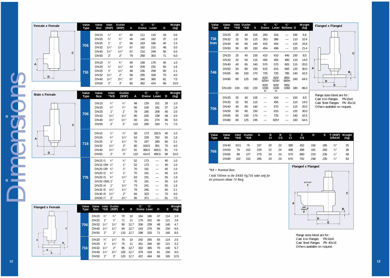
DN15 1⁄2" 1⁄2" 40 111 133 29 0.6DN20 3⁄4" 3⁄4" 46 140 162 37 1.0DN25 1" 1" 56 163 186 40 1.5DN32 11⁄4" 11⁄4" 67 182 215 48 3.0DN40 11⁄2" 11⁄2" 67 216 249 56 4.5DN50 2" 2" 79 268 303 71 6.0
DN15 1⁄2" 3⁄4" 40 158 178 40 1.0DN20 3⁄4" 11⁄4" 44 209 232 55 1.6DN25 1" 11⁄2" 48 235 258 60 2.1DN32 11⁄4" 2" 58 295 328 70 4.0DN40 11⁄2" 21⁄2" 67 340 380 81 7.0DN50 2" 3" 80 382 424 96 10.0
706
706
716
DN15 1⁄2" 3⁄4" 58 173 192.5 40 1.0DN20 3⁄4" 11⁄4" 63 229 252 55 1.6DN25 1" 11⁄2" 70 257 280 60 2.1DN32 11⁄4" 2" 80 318.5 351 70 4.0DN40 11⁄2" 21⁄2" 91 366.5 405.5 81 7.0DN50 2" 3" 110 414.5 456.5 96 10.0
DN15 /1 1⁄2" 3⁄4" 52 173 — 40 1.0DN15 /2M 1⁄2" 1" 52 173 — 40 1.0DN20 /2R 3⁄4" 1" 70 191 — 45 1.0DN20 /2 3⁄4" 1" 70 191 — 45 1.0DN20 /3 3⁄4" 11⁄4" 63 231 — 55 1.6DN25 /2M1 1" 1" 70 191 — 45 1.0DN25 /4 1" 11⁄4" 73 241 — 55 1.6DN32 /5 11⁄4" 11⁄2" 78 265 — 60 2.1DN40 /6 11⁄2" 2" 84 323 — 70 4.0DN50 /7 2" 21⁄2" 95 371 — 81 7.0
716
776
Valve Valve Inlet Outlet ‘C’ ‘C’ WeightType Size (BSP) (BSP) A Dome Lever D (kg)
Valve Valve Inlet Outlet ‘C’ ‘C’ WeightType Size *NB (BSP) A Dome Lever D (kg)
Female x Female
Male x Female
AB
DE
C
DN20 3⁄4" 3⁄4" 70 10 164 186 37 114 1.9DN25 1" 1" 71 11 179 202 40 121 2.6DN32 11⁄4" 11⁄4" 90 12.7 206 239 48 140 4.7DN40 11⁄2" 11⁄2" 94 12.7 243 276 56 150 6.5DN50 2" 2" 110 12.7 298 333 71 165 8.5
DN20 3⁄4" 11⁄4" 75 10 242 265 55 114 2.5DN25 1" 11⁄2" 75 11 261 284 60 121 3.2DN32 11⁄4" 2" 95 12.7 332 365 70 140 5.7DN40 11⁄2" 21⁄2" 105 12.7 379 418 81 150 9.0DN50 2" 3" 120 12.7 422 464 96 165 12.5
Valve Valve Inlet Outlet ‘C’ ‘C’ WeightType Size *NB (BSP) A B Dome Lever D E (kg)
Flanged x Female
706
716
12
DN15 1⁄2" 1⁄2" 48 129 151 29 1.0DN20 3⁄4" 3⁄4" 56 159 181 37 1.6DN25 1" 1" 78 185 208 40 2.0DN32 11⁄4" 11⁄4" 90 205 238 48 3.5DN40 11⁄2" 11⁄2" 93 241 274 56 5.0DN50 2" 2" 110 299 334 71 7.0

DN25 DN32 DN40 DN50 DN65 DN80DN100 DN20 DN15 DN20 DN20 DN25 DN32 DN40 DN50
0.35 69.6 109 178 275 467 711 1098
1.0 115 182 297 459 781 1188 1836 14 26.9 26.9 71.3 77.5 103 163 265
2.0 181 287 468 723 1231 1872 2894 21 40.3 40.3 107 116 153 244 397
3.0 242 384 626 968 1646 2505 3872 30.5 58.7 58.7 155 169 224 356 579
4.0 303 482 786 1215 2066 3144 4859 38.2 73.4 73.4 205 211 279 444 723
5.0 365 580 945 1462 2486 3782 5846 45.8 88.0 88.0 246 253 335 533 868
6.0 427 678 1105 1708 2906 4421 6834 54 103 103 287 296 391 621 1012
7.0 488 776 1265 1955 3326 5060 7821 61 117 117 328 338 446 710 1156
8.0 550 874 1424 2202 3746 5699 8808 69 132 132 369 380 502 798 1301
9.0 611 972 1584 2449 4165 6337 9795 76 147 147 410 422 558 887 1445
10.0 673 1070 1744 2696 4585 6976 10783 84 161 161 451 464 613 976 1589
12.0 796 1267 2063 3189 5425 8253 12757 99 190 190 533 548 725 1153 1878
12.5 827 1316 2143 3313 5635 8573 13251 103 198 198 553 570 752 1197 1950
14.0 920 1463 2382 3683 6265 9531 14732 115 220 220 614 633 836 1330 2166
16.0 1043 1659 2701 4177 7104 10808 16706 129 249 249 696 717 948 1507 2455
18.0 1166 1855 3021 4670 7944 12086 18681 145 278 278 778 801 1059 1684 2743
20.0 1289 2051 3340 5164 8784 13363 20655 160 307 307 860 886 1171 1862 3032
22.0 1413 2247 3659 5658 9623 14641 22630 175 337 337 942 970
24.0 1536 2443 3979 6151 10463 15918 24605 190 366 366 1024 1054
26.0 1659 2639 4298 6645 11303 17196 205 395 395 1106 1139
28.0 1782 2835 4617 7138 12142 18473 220 424 424 1187 1223
30.0 1906 3031 4936 7632 12982 19751 236 454 454 1269 1307
32.0 2029 3227 5256 8126 13822 21028
34.0 2152 3423 5575 8619 14661
36.0 2276 3619 5894 9113
38.0 2399 3815 6214 9607
40.0 2522 4011 6533 10100
AIR CAPACITY CHART (l/s) @ 0.3 BARG OR 10% OVERPRESSURE* AND 15°C
Valve Type746 #(BS6759 Pt2)
Valve Type776 (AD MERKBLATT A2)
†† § **
Air
Cap
acity
15
†DN20 x DN25§DN15 x (DN20 or DN25)†(DN20 or DN25 x DN25)**DN20 x DN32
* Minimum overpressure = 0.07 Barg at set pressure less than 1.0 Barg.
# The 746 can be sized/certified to ASME VIII and AD Merkblatt A2 - contact factory for details.
SetPressure(Barg)
/1 /2/2R /2M /2M1 /3 /4 /5 /6 /7
DN15 DN20 DN25 DN32 DN40 DN50 DN15 DN20 DN25 DN32 DN40 DN50
0.35 5.03 14.5 19.2 31.5 49.5 77.5 18.3 52.6 69.6 111 180 279
1.0 8.97 25.9 34.2 56.3 88.3 138 31.2 89.9 119 189 308 476
2.0 13.9 40.0 52.9 87.0 136 214 48.8 140 186 295 481 744
3.0 18.1 52.4 69.2 114 178 280 63.5 183 242 384 626 968
4.0 22.8 65.8 86.9 143 224 351 79.7 230 303 482 786 1215
5.0 27.3 79.1 105 172 270 422 95.9 276 365 580 945 1462
6.0 32.0 92.5 122 201 315 493 112 323 427 678 1105 1708
7.0 36.6 106 140 230 361 565 128 369 488 776 1265 1955
8.0 41.3 119 158 259 406 636 144 416 550 874 1424 2202
9.0 45.9 133 175 288 452 708 161 463 611 972 1584 2449
10.0 50.5 146 193 317 497 779 177 509 673 1070 1744 2696
12.0 59.8 173 228 375 588 921 209 603 796 1267 2063 3189
12.5 62.1 179 237 390 611 957 217 626 827 1316 2143 3313
14.0 242 696 920 1463 2382 3683
16.0 274 789 1043 1659 2701 4177
18.0 306 882 1166 1855 3021 4670
20.0 339 976 1289
22.0 371 1069
24.0 403 1162
26.0 436
28.0 468
30.0 501
32.0 533
34.0
36.0
38.0
40.0
AIR CAPACITY CHART (l/s) @ 0.3 BARG OR 10% OVERPRESSURE* AND 15°C
Valve Type706 (BS6759 Pt2)
Valve Type716 (BS6759 Pt2)
SetPressure(Barg)
Air
Cap
acity
14
Useful ConversionsNm3/h = 1/sec x 3.60SCFM = 1/sec x 2.12
Maximum pressure per size based on716 bronze valve. For 716 C1 and SSvalves refer to page 23.
Other GasesIf you wish to use the valve on other compatible gases, the sizing details above canbe used. The valve capacity will however change depending on the specific gravity ofthe flowing gas. Multiply the valve air capacity by 1/ SG to give the gas capacity.SG = specific gravity (relative to air = 1).
* Minimum overpressure = 0.07 Barg at set pressure less than 1.0 Barg.

DN25 DN32 DN40 DN50 DN65 DN80 DN100 DN25 DN32 DN40 DN50 DN65 DN80 DN40 DN50 DN65 DN80
0.35 124 198 322 498 847 1289 1992 161 257 419 648 1101 1676 402 716 1119 1611
1.0 269 429 698 1079 1836 2793 4317 297 472 769 1189 2022 3076 893 1587 2480 3571
2.0 457 727 1183 1830 3112 4735 7318 486 773 1258 1945 3309 5034 1485 2640 4125 5940
3.0 635 1010 1645 2543 4326 6581 10173 650 1033 1683 2601 4425 6732 2065 3673 5738 8262
4.0 795 1265 2060 3185 5417 8241 12738 813 1294 2107 3257 5541 8429 2592 4609 7201 10369
5.0 955 1519 2475 3826 6508 9901 15303 977 1554 2531 3913 6656 10127 3119 5545 8664 12475
6.0 1115 1774 2889 4467 7598 11560 17869 1141 1815 2955 4567 7772 11825 3645 6482 10127 14582
7.0 1276 2029 3304 5108 8689 13220 20433 1305 2075 3380 5225 8888 13522 4172 7418 11591 16689
8.0 1436 2283 3719 5750 9780 14880 22999 1469 2336 3804 5881 10004 15220 4699 8355 13054 18795
9.0 1596 2538 4134 6391 10871 16539 25565 1632 2596 4228 6537 11120 16917 5226 9291 14517 20902
10.0 1756 2793 4549 7032 11962 18199 28130 1796 2857 4653 7193 12235 18615 5752 10228 15980 23009
12.0 2076 3302 5378 8315 14143 21518 33260 2124 3378 5501 8505 14467 22010 6806 12100 18906 27222
12.5 2156 3429 5586 8636 14689 22348 34543 2206 3508 5713 8833 15024 22859 7069 12569 19638 28276
14.0 2397 3811 6208 9598 16325 24838 38391 2451 3898 6350 9817 16699 25405 7859 13974 21832 31436
16.0 2717 4321 7038 10880 18587 28157 43522 2779 4419 7198 11129 18930 28800 8912 15847 24759 35649
18.0 3037 4830 7867 12163 20689 31476 48652 3107 4940 8047 12441 21162 32196 9965 17720 27685 39863
20.0 3357 5339 8697 13446 22871 34795 53783 3434 5461 8896 13753 23393 35591 11019 19593 30612 44076
22.0 3678 5849 9526 14728 25052 38115 58913 3762 5982 9744 15065 25625 38986 12072 21466 33538 48289
24.0 3998 6358 10356 16011 27234 41434 64044 4089 6503 10593 16377 27857 42381 13126 23338 36464 52503
26.0 4318 6868 11186 17293 29416 44753
28.0 4638 7377 12015 18576 31598 48073
30.0 4959 7886 12845 19859 33779 51392
32.0 5279 8396 13675 21142 35961 54711
STEAM CAPACITY CHART (kg/h)
Valve Type746 #(BS6759 Pt1 @ 5% Overpressure)†
Valve Type756 (BS6759 Pt1 @ 5%
Overpressure)†
Metal Seat Valve Type766 (BS6759 Pt1 @ 10%
Overpressure)*
* Minimum overpressure = 0.07 Barg at set pressure less than 0.7 Barg.† Minimum overpressure = 0.07 Barg at set pressure less than 1.0 Barg.
# The 746 can be sized/certified to ASME VIII and AD Merkblatt A2 - contact factory for details.
Stea
m C
apac
ity
17
SetPressure(Barg)
DN15 DN20 DN25 DN32 DN40 DN50 DN15 DN20 DN25 DN32 DN40 DN50
0.35 108 11.1 32.0 42.3 69.5 109 171 35.6 103 136 216 351 543
1.0 120 22.3 64.4 85.1 140 219 344 70.5 203 269 427 696 1075
2.0 134 36.6 106 140 230 360 564 125 359 475 755 1230 1902
3.0 144 49.4 143 188 310 486 761 167 480 635 1010 1645 2543
4.0 152 62.0 179 237 389 610 955 209 602 795 1265 2060 3185
5.0 159 74.5 215 285 468 734 1150 251 723 955 1519 2475 3826
6.0 165 87.1 252 333 547 857 1344 293 844 1115 1774 2889 4467
7.0 170 99.7 288 381 626 981 1538 335 965 1276 2029 3304 5108
8.0 175 112 324 429 705 1105 1732 377 1086 1436 2283 3719 5750
9.0 180 125 361 477 784 1229 1926 419 1207 1596 2538 4134 6391
10.0 184 138 397 525 863 1353 2120 461 1329 1756 2793 4549 7032
12.0 192 163 470 621 1021 1601 2508 545 1571 2076 3302 5378 8315
12.5 193 169 488 645 1061 1663 2605 566 1632 2156 3429 5586 8636
14.0 198 629 1831 2397 3811 6208 9598
16.0 204 714 2056 2717 4321 7038 10880
18.0 210 798 2298 3037 4830 7867 12163
20.0 215 882 2540 3357
22.0 220 966 2783
24.0 224
26.0 228
28.0 232
30.0 236
32.0 239
34.0 243
36.0 246
38.0 249
40.0 252
STEAM CAPACITY CHART (kg/h)
Valve Type706 (BS6759 Pt1 @ 10% Overpressure)*
Valve Type716 (BS6759 Pt1 @ 5% Overpressure)†
SetPressure(Barg)
SaturatedSteam
Temp. °C
* Minimum overpressure = 0.07 Barg at set pressure less than 0.7 Barg.† Minimum overpressure = 0.07 Barg at set pressure less than 1.0 Barg.St
eam
Cap
acity
16
Maximum pressure per size based on716 bronze valve. For 716 C1 and SSvalves refer to page 23.
Useful Conversionslbs/h = kg/h x 2.2046
Other TemperaturesThe above tables are based on saturatedsteam, at the temperatures shown.For steam systems operating at highertemperatures, the above capacities willneed to be derated by using the superheat correction factor.If you do not already have these figures,please consult the Bailey sales office.

DN25 DN32 DN40 DN50 DN65 DN80 DN100
0.35 105 167 272 420 715 1088
1.0 170 270 440 680 1157 1761 2722
2.0 240 382 622 962 1637 2490 3849
3.0 294 468 762 1178 2005 3050 4714
4.0 340 540 880 1361 2315 3522 5443
5.0 380 604 984 1521 2588 3937 6086
6.0 416 662 1078 1667 2835 4313 6666
7.0 449 715 1164 1800 3062 4659 7210
8.0 481 764 1245 1924 3273 4980 7698
9.0 510 811 1320 2041 3472 5282 8165
10.0 537 854 1392 2152 3660 5568 8606
12.0 589 936 1525 2357 4009 6099 9428
12.5 601 955 1556 2406 4092 6225 9622
14.0 636 1011 1647 2546 4330 6588 10183
16.0 680 1081 1760 2722 4629 7043 10886
18.0 721 1146 1867 2887 4910 7470 11547
20.0 760 1208 1968 3043 5176 7874 12171
22.0 797 1267 2064 3191 5428 8259 12765
24.0 832 1324 2156 3333 5670 8626 13332
26.0 866 1378 2244 3469 5901 8978
28.0 899 1430 2329 3600 6124 9317
30.0 931 1480 2410 3727 6339 9644
32.0 961 1528 2490 3849 6547 9960
34.0 991 1575 2566 3967 6748
36.0 1019 1621 2641 4082
38.0 1047 1666 2713 4194
40.0 1074 1709 2783 4303
WATER CAPACITY CHART (l/min) @ 10% OVERPRESSURE* @ 20°C
Valve Type746 #(BS6759 Pt3)
SetPressure(Barg)
* Minimum overpressure = 0.07 Barg at set pressure less than 0.7 Barg.
# The 746 can be sized/certified to ASME VIII and AD Merkblatt A2 - contact factory for details. Wat
er C
apac
ity
19
DN15 DN20 DN25 DN32 DN40 DN50 DN15 DN20 DN25 DN32 DN40 DN50
0.35 10.3 29.8 39.4 64.8 102 159 27.6 79.4 105 167 272 420
1.0 16.7 48.3 63.8 105 164 258 44.6 129 170 270 440 680
2.0 23.6 68.3 90.2 148 233 364 63.1 182 240 382 622 962
3.0 28.9 83.6 111 182 286 446 77.3 223 294 468 762 1178
4.0 33.4 96.5 128 210 329 515 89.3 257 340 540 880 1361
5.0 37.4 108 143 235 368 576 99.8 287 380 604 984 1521
6.0 40.9 118 156 257 403 631 109 315 416 662 1078 1667
7.0 44.2 128 169 278 435 682 118 340 449 715 1164 1800
8.0 47.3 137 180 297 465 729 126 364 481 764 1245 1924
9.0 50.1 145 191 315 493 773 134 386 510 811 1320 2041
10.0 52.8 153 202 332 520 815 141 406 537 854 1392 2152
12.0 57.9 167 221 363 570 893 155 445 589 936 1525 2357
12.5 59.1 171 226 371 581 911 158 454 601 955 1556 2406
14.0 167 481 636 1011 1647 2546
16.0 179 514 680 1081 1760 2722
18.0 189 545 721 1146 1867 2887
20.0 200 575 760
22.0 209 603
24.0 219 639
26.0 227
28.0 236
30.0 244
32.0 252
34.0
36.0
38.0
40.0
WATER CAPACITY CHART (l/min) @ 10% OVERPRESSURE* @ 20°C
Valve Type706 (BS6759 Pt3)
Valve Type716 (BS6759 Pt3)
SetPressure(Barg)
* Minimum overpressure = 0.07 Barg at set pressure less than 0.7 Barg.Wat
er C
apac
ity
18
Useful ConversionsIgpm = 1/min x 0.22m3/min = 1/min x 0.001
Other LiquidsIf you wish to use the valve on other compatible liquids,the sizing details above can be used. The valve capacitywill however change depending on the specific gravity ofthe flowing liquid. Multiply the valve water capacity by1/ SG to give the liquid capacity.SG = specific gravity (relative to water = 1).
Maximum pressure per size based on716 bronze valve. For 716 C1 and SSvalves refer to page 23.

HOT WATER CAPACITY CHART (kW) fOR A PRESSURISED (un-vented) SYSTEM
Valve Type746 (BS6759 Pt1 @ 5% Overpressure)†
Resilient Seat Valve Type 766 (BS759 @ 10% Overpressure)*
DN25 DN32 DN40 DN50 DN65 DN80 DN100 DN40 DN50 DN65 DN80
0.35 227 360 587 907 1543 2547 3628 65 109 173 259
1.0 235 374 608 941 1600 2434 3762 180 316 500 720
2.0 309 492 801 1239 2107 3206 4956 362 646 1010 1440
3.0 398 633 1031 1594 2711 4124 6375 534 970 1490 2150
4.0 498 792 1291 1996 3394 5164 7983 710 1280 1990 2870
5.0 599 952 1551 2398 4078 6204 9590 900 1594 2490 3580
6.0 699 1112 1811 2799 4762 7244 11198 1080 1910 2990 4300
7.0 799 1271 2071 3201 5445 8285 12805 1260 2256 3500 5050
8.0 900 1431 2331 3603 6129 9721 14413 1442 2574 4010 5780
9.0 1000 1590 2591 4005 6813 10365 16020 1622 2900 4514 6500
10.0 1100 1750 2851 4407 7496 11405 17628 1806 3212 5020 7210
12.0 1301 2069 3370 5211 8863 13485 20843 2170 3860 6020 8630
12.5 1351 2149 3500 5412 9205 14005 21647 2258 4020 6265 8992
14.0 1501 2388 3890 6015 10231 15565 24058 2522 4500 7000 10080
16.0 1703 2708 4410 6818 11598 17645 27274 2882 5124 8016 11530
18.0 1903 3027 4930 7622 12965 19725 30489 3244 5770 9014 12980
20.0 2104 3346 5450 8426 14332 21805 33704 3602 6406 10000 14420
22.0 2304 3665 5970 9230 15699 23885 36919 3962 7036 11014 15840
24.0 2505 3984 6490 10034 17067 25965 40134 4326 7684 12000 17290
26.0 2706 4304 7010 10837 18434 28045
28.0 2907 4623 7530 11641 19801 30125
30.0 3107 4942 8050 12445 21168 32206
32.0 3308 5261 8569 13249 22536 34286
34.0 3509 5580 9089 14053 23903
36.0 3710 5900 9609 14856
38.0 3910 6219 10129 15660
40.0 4111 6538 10649 16464
* Minimum overpressure = 0.07 Barg at set pressure less than 0.7 Barg.† Minimum overpressure = 0.07 Barg at set pressure less than 1.0 Barg.
Hot
Wat
er C
apac
ity
21
SetPressure(Barg)
DN15 DN20 DN25 DN32 DN40 DN50 DN15 DN20 DN25 DN32 DN40 DN50
0.35 14.3 41.4 54.7 89.9 141 221 54.5 157 208 330 538 832
1.0 16.4 47.5 62.8 103 162 254 61.9 178 236 374 611 944
2.0 23.1 66.9 88.4 145 228 357 78.2 225 298 473 771 1192
3.0 30.9 89.4 118 194 304 477 105 301 398 633 1031 1594
4.0 38.8 112 148 244 382 599 131 377 498 792 1291 1996
5.0 46.7 135 178 293 460 720 157 453 599 952 1551 2398
6.0 54.6 158 208 343 537 842 184 529 699 1112 1811 2799
7.0 62.5 181 239 392 615 964 210 605 799 1271 2071 3201
8.0 70.5 203 269 442 693 1085 236 681 900 1431 2331 3603
9.0 78.3 226 299 491 770 1207 263 757 1000 1590 2591 4005
10.0 86.2 249 329 541 848 1329 289 833 1100 1750 2851 4407
12.0 102 294 389 640 1003 1572 342 984 1301 2069 3370 5211
12.5 106 306 404 665 1042 1633 355 1022 1351 2149 3500 5412
14.0 394 1136 1501 2388 3890 6015
16.0 447 1288 1703 2708 4410 6818
18.0 500 1440 1903 3027 4930 7622
20.0 553 1592 2104
22.0 605 1744
24.0
26.0
28.0
30.0
32.0
34.0
36.0
38.0
40.0
* Minimum overpressure = 0.07 Barg at set pressure less than 0.7 Barg.† Minimum overpressure = 0.07 Barg at set pressure less than 1.0 Barg.
NOTE:Pressurised (un-vented) hot water systems have the entire discharge capacity handled solely by the valve.Open vented systems take into account the discharge capacities of the vent. Hence the equivalent discharge ofthe valve is considered to be double the above chart capacities.
HOT WATER CAPACITY CHART (kW) FOR A PRESSURISED (un-vented) SYSTEM
Valve Type706 (BS6759 Pt1 @ 10% Overpressure)*
Valve Type716 (BS6759 Pt1 @ 5% Overpressure)†
SetPressure(Barg)
Hot
Wat
er C
apac
ity
20
Maximum pressure per size based on716 bronze valve. For 716 C1 and SSvalves refer to page 23.

Part No Barg Psig Colour codeC0074 0.35 – 1.0 5 – 15 RedC2133 1.0 – 1.7 15 – 25 BlueC2134 1.7 – 2.4 25 – 35 OrangeC2135 2.4 – 4.1 35 – 60 Orange/BlueC2136 4.1 – 6.9 60 – 100 Green/WhiteC2137 6.9 – 10.3 100 – 150 Green/BlueC2138 10.3 – 12.4 150 – 180 White/BlueC2181 12.4 – 15.5 180 – 225 —C0623 15.5 – 18.6 225 – 270 WhiteC2169 18.6 – 22.1 270 – 320 —C0645 22.1 – 26.5 320 – 384 Red/YellowC2201 26.5 – 27.6 384 – 400 —C0651 27.6 – 32.0 400 – 464 Red/Green
DN15 Spring Range
Part No Barg Psig Colour codeC0686 0.35 – 1.0 5 – 14 RedC0688 1.0 – 2.1 14 – 30 BlueC0689 2.1 – 2.8 30 – 40 OrangeC2125 2.8 – 3.8 40 – 55 Orange/BlueC0690 3.8 – 5.5 55 – 80 PurpleC2126 5.5 – 7.6 80 – 110 Green/WhiteC0691 7.6 – 10.3 110 – 150 Green/BlueC2127 10.3 – 12.4 150 – 180 White/BlueC2178 12.4 – 15.5 180 – 225 —C0693 15.5 – 18.6 225 – 270 WhiteC2170 18.6 – 20.3 270 – 295 —C0694 20.3 – 24.5 295 – 355 Red/Yellow
DN20 Spring Range
Part No Barg Psig Colour codeC2119 0.35 – 1.0 5 – 14 RedC2120 1.0 – 1.7 14 – 25 BlueC2121 1.7 – 3.1 25 – 45 OrangeC2114 3.1 – 4.1 45 – 60 Orange/BlueC2113 4.1 – 5.5 60 – 80 PurpleC2122 5.5 – 8.6 80 – 125 Green/WhiteC2123 8.6 – 10.7 125 – 155 Green/BlueC2124 10.7 – 12.8 155 – 185 White/BlueC2202 12.8 – 13.2 185 – 192 —C2234 13.2 – 15.4 192 – 223 —C2203 15.4 – 17.6 223 – 255 —C2235 17.6 – 20.5 255 – 297 —
DN25 Spring Range
Part No Barg Psig Colour codeC0452 0.35 – 1.0 5 – 14 RedC0457 1.0 – 1.7 14 – 25 BlueC0461 1.7 – 3.1 25 – 45 OrangeC0467 3.1 – 4.1 45 – 60 Orange/BlueC0469 4.1 – 5.5 60 – 80 PurpleC0472 5.5 – 8.6 80 – 125 Green/WhiteC0475 8.6 – 10.3 125 – 150 Green/BlueC0476 10.3 – 12.8 150 – 185 White/BlueC0477 11.4 – 13.8 166 – 200 —C0478 12.6 – 15.2 183 – 220 —C0479 13.9 – 16.8 202 – 243 —C0480 15.4 – 18.5 223 – 268 —
DN32 Spring Range
Part No Barg Psig Colour codeC0508 0.35 – 1.0 5 – 14 RedC0492 1.0 – 1.7 14 – 25 BlueC0495 1.7 – 3.1 25 – 45 OrangeC0498 3.1 – 4.1 45 – 60 Orange/BlueC0499 4.1 – 5.5 60 – 80 PurpleC0501 5.5 – 8.6 80 – 125 Green/WhiteC0503 8.6 – 10.3 125 – 150 Green/BlueC0504 10.3 – 12.8 150 – 185 White/BlueC0505 11.4 – 13.8 166 – 200 —C0506 12.6 – 15.2 183 – 220 —C0507 15.4 – 18.5 223 – 268 —
DN40 Spring Range
Part No Barg Psig Colour codeC0919 0.35 – 1.0 5 – 14 RedC0922 1.0 – 1.7 14 – 25 BlueC0924 1.7 – 3.1 25 – 45 OrangeC1400 3.1 – 4.1 45 – 60 Orange/BlueC0928 4.1 – 5.5 60 – 80 PurpleC0930 5.5 – 8.6 80 – 125 Green/WhiteC0933 8.6 – 10.3 125 – 150 Green/BlueC0934 10.3 – 12.8 150 – 185 White/BlueC0935 11.4 – 13.8 166 – 200 —C0936 12.8 – 15.4 185 – 223 —C0937 14.5 – 17.4 210 – 253 —C0939 15.4 – 18.5 223 – 268 —
DN50 Spring Range
716 SPRING SELECTION CHARTS
• Springs up to 12.5 Barg (181 Psig) listed above for all materials comply with the requirements of BS6759: Part 1.
• The cast iron 716 is only available up to 13 Barg (188 Psig) on any medium.
• The stainless steel 716 is only available up to 12.5 Barg (181 Psig) on any medium.
• Stainless steel springs are available for 716 to the same pressures as shown above.
• Spring charts for 746/756/766/776 are available on request.
716
Spri
ngs
23
706
Spri
ngs
Part No Barg Psig Colour codeC2193 0.35 – 1.0 5 – 15 RedC2194 1.0 – 1.7 15 – 25 BlueC2195 1.7 – 2.4 25 – 35 OrangeC2196 2.4 – 3.5 35 – 50 Orange/BlueC2197 3.5 – 5.5 50 – 80 Green/WhiteC2198 5.5 – 8.3 80 – 120 Green/BlueC2199 8.3 – 12.5 120 – 180 White/Blue
DN15 Spring Range
Part No Barg Psig Colour codeC2187 0.35 – 1.0 5 – 15 RedC2188 1.0 – 1.7 15 – 25 BlueC2189 1.7 – 3.5 25 – 50 OrangeC2190 3.5 – 6.9 50 – 100 Orange/BlueC2191 6.9 – 10.3 100 – 150 PurpleC2192* 10.3 – 12.5 150 – 180 Green/WhiteC2200† 10.3 – 12.5 150 – 180 White/Blue
* For air or steam† For water or liquids
DN20 Spring Range
Part No Barg Psig Colour codeC2220 0.35 – 1.0 5 – 15 RedC0174 1.0 – 1.7 15 – 25 BlueC2213 1.7 – 2.4 25 – 35 OrangeC2221 2.4 – 4.1 35 – 60 Orange/BlueC2214 4.1 – 5.5 60 – 80 PurpleC2222 5.5 – 8.3 80 – 120 Green/WhiteC2215 8.3 – 10.3 120 – 150 Green/BlueC2223 10.3 – 12.5 150 – 180 White/Blue
DN32 Spring Range
Part No Barg Psig Colour codeC2224 0.35 – 1.0 5 – 15 RedC2216 1.0 – 1.7 15 – 25 BlueC0709 1.7 – 2.4 25 – 35 OrangeC2225 2.4 – 4.1 35 – 60 Orange/BlueC2226 4.1 – 5.5 60 – 80 PurpleC2217 5.5 – 8.3 80 – 120 Green/WhiteC2208 8.3 – 10.3 120 – 150 Green/BlueC2218 10.3 – 12.5 150 – 180 White/Blue
DN40 Spring Range
Part No Barg Psig Colour codeC0139 0.35 – 1.0 5 – 15 RedC0145 1.0 – 1.7 15 – 25 BlueC0147 1.7 – 2.4 25 – 35 OrangeC2182 2.4 – 4.1 35 – 60 Orange/Blue
Air and Pumped Liquids onlyC2183 4.1 – 5.5 60 – 80 PurpleC2184 5.5 – 8.3 80 – 120 Green/WhiteC2185 8.3 – 10.3 120 – 150 Green/BlueC2186 10.3 – 12.5 150 – 180 White/Blue
Steam and Hot Water onlyC2183 4.1 – 6.9 60 – 100 PurpleC2184 6.9 – 10.3 100 – 150 Green/WhiteC2185 10.3 – 12.5 150 – 180 Green/Blue
DN25 Spring Range
Part No Barg Psig Colour codeC2227 0.35 – 1.0 5 – 15 RedC0718 1.0 – 1.7 15 – 25 BlueC0719 1.7 – 2.4 25 – 35 OrangeC2219 2.4 – 4.1 35 – 60 Orange/BlueC2228 4.1 – 5.5 60 – 80 PurpleC2229 5.5 – 8.3 80 – 120 Green/WhiteC2209 8.3 – 10.3 120 – 150 Green/BlueC2230 10.3 – 12.5 150 – 180 White/Blue
DN50 Spring Range
706 SPRING SELECTION CHARTS
22
Springs listed above comply with the requirements of BS6759: Part 1.

Spec
ifica
tion
700 SERIES TECHNICAL SPECIFICATION
*For higher back pressures consult factory. **Resilient 766 is limited to 10%.†For maximum pressure per size and material refer to capacity and spring charts, pages 14 to 23.††716 EPDM Seat, max pressure of 12.5 Barg on DN 15, 20, 25 and 18 Barg on DN 32, 40, 50.#746 is also available ASME VIII and AD Merkblatt A2 certified, details available on request.
Seat BodyEPDM (WRC) –40°C to 95°C Bronze –196°C to 220°CEPDM –50°C to 150°C Cast Iron 0°C to 220°CAflas –10°C to 200°C Carbon Steel –29°C to 427°CBrass –59°C to 232°C Stainless Steel –270°C to 427°CStainless Steel –90°C to 427°CViton –10°C to 200°CKEL F –196°C to +60°C
Fig. No 706 716 746 756 766 776
Body BronzeBronze Cast Steel Cast IronMaterial Cast Iron Cast Steel BronzeStainless Steel Cast SteelStainless Steel
Code BS6759 AD MERKBLATTApprovals Part 1, 2, & 3 1, 2, & 3 1, 2, & 3# 1 1 A2
Top Guided Yes Yes Yes Yes Yes Yes
Lift High Lift Full Lift Full Lift Full Lift High Lift Full Lift
DN15-50 DN15-50 DN25-100 DN25-80 DN40-80 DN15-50Size Range 1⁄2" – 2" 1⁄2" – 2" 1" – 4" 1" – 3" 11⁄2" – 3" 1⁄2" – 2"
Orifice Areas(mm2)DN15 126 109 — — —DN20 364 314 — — —DN25 481 415 415 415 — Sizing dataDN32 791 660 660 660 — to TUVDN40 1240 1075 1075 1075 2280 availableDN50 1943 1662 1662 1662 4054 on request.DN65 — — 2827 2827 6334DN80 — — 4301 4301 9121DN100 — — 6648 — —
Pressure Range†(Barg) 0.35 to 12.5 0.35 to 32 0.35 to 40 0.35 to 24 0.35 to 24 1 to 41.3
Temp Range (°C)(with suitable material) –59 to +220 –90 to +260 –40 to +427 –29 to +300 –29 to +230 –196 to +60
Connection Screwed Screwed Flanged Flanged Flanged ScrewedFlanged Flanged
Trim Options Brass Stainless Stainless Stainless Stainless KEL FEPDM (WRC) Aflas Aflas EPDM EPDM (PCTFE)Viton EPDM†† EPDM
Cap Options DomeDome Dome Open lever Open lever Open lever DomeOpen lever Open lever Packed lever
Kdr. Cert. Coeff.Steam/Hot Water/Gases 0.173 0.7 0.7 0.716 0.4 —
Kdr. Cert. Coeff.Liquids 0.149 0.46 0.46 — — —
Maximum Brz 5.5 BargBack CI 5.5 Barg CS 16 Barg CI 6 Barg Brz 5.5 BargPressure Brz 5.5 Barg SS 5.5 Barg SS 16 Barg CS 12 Barg CS 12 Barg SS 5.5 Barg
Maximum 80% 80% 80% — — 80%Back 10% 10% 10% 50% 50%** 10%Pressure* — — 40% — — —
MaterialTemperatureLimitations
24
ConstantBuilt-upVariable
700 SeriesS a f e t y R e l i e f V a l v e s
700
Seri
es
7 4 6
7 6 6
7 7 6
7 1 6
7 0 6
7 5 6
25