load-carrying capacity and practical … capacity and practical design ... the circular hollow...
TRANSCRIPT
Advanced Steel Construction Vol. 6, No. 4, pp. 976-1000 (2010) 976
LOAD-CARRYING CAPACITY AND PRACTICAL DESIGN METHOD OF WELDED HOLLOW SPHERICAL JOINTS IN SPACE LATTICED STRUCTURES
Xing Li
School of Civil Engineering, Zhejiang Shuren University, Hangzhou 310015, China
E-mail: [email protected]
Received: 31 January 2010; Revised: 7 June 2010; Accepted: 25 June 2010
ABSTRACT: A newly developed space structure, the polyhedron space frame based on the bubble theory, is adopted in Chinese National Swimming Center-the Water Cube for 2008 Beijing 29th Olympic Games. Circular hollow sections, square hollow sections and rectangular hollow sections are employed as structural members, while welded hollow spherical joints are employed to connect the members. However, for welded hollow spherical joints connected with rectangular/square steel tubes, no previous study has been reported and no design criterion has been established. This paper investigates the structural behavior and load-carrying capacity of the joints subject to axial forces, bending moments and combined loading of the two. Based on the elastic-perfectly plastic model and the Von-Mises yield criterion, a finite element model for the analysis of the joints is established, in which the effect of geometric nonlinearity is taken into account. A major parametric study is then carried out employing this model. Experiments on ten typical full-scale joints are conducted to understand directly the structural behavior and the collapse mechanism of the joint, and also to validate the finite element model. A simplified theoretical solution is also derived for the loading-carrying capacity of the joint based on the punching shear failure model, and the basic form for the design equation is obtained. Finally, by utilizing the results from the simplified theoretical solution, finite element analysis and experimental study, the practical design method is established for the load-carrying capacity of the joints subject to axial forces, bending moments and the combined loading. The results from this study can be applied for direct design use, and also provide a reference for the revision of relevant design codes
Keywords: Space structure; welded hollow spherical joints; rectangular steel tubes; load-carrying capacity; finite element analysis; material nonlinearity; geometrical nonlinearity
1. INTRODUCTION A newly developed space structure, the polyhedron space frame based on the bubble theory, is adopted in Chinese National Swimming Center-the Water Cube for 2008 Beijing 29th Olympic Games. Water cube is located in the central area of the Olympic Green, it is a cubic with the size of 177mx177mx31m, with a total architectural area of 80,000m2, as is shown in Figure 1. It has a seating capacity of 11,000 plus 6000 temporary seats, and served as the centrepiece of 2008 Olympic Games venue for swimming, diving, synchronised swimming and water polo events. It also provided multifunctional recreation, sports and fitness services for the public after the Event. The project was completed on time, despite its complexity and a fast-track schedule of design and construction. The interior view of the project in construction is shown in Figure 2. Three types of steel hollow sections are applied in the space frame: the circular hollow section, the square hollow section and the rectangular hollow section. Herein, the circular hollow section is used in the internal members and the square or rectangular hollow section is used for members on the opposite surfaces of roofs and walls for convenience of connection with the ETFE air pillow (Figure 2).
The Hong Kong Institute of Steel Construction www.hkisc.org

977 Xing Li
Two kinds of joint for rigid connection of the steel hollow section members are proposed by Chinese relevant Code or Specifications [1,2,3]: the welded hollow spherical joints (WHSJ), and the intersecting joint. The welded hollow spherical joints, which are popular for the domestic latticed structure for recent years, are mainly employed for connections of the members in this project. At present, studies on structural properties and load carrying capacity of WHSJ are aimed at the connections with the circular hollow pipes [4,5,6]. Ultimate bearing capacity of the WHSJ connected with circular pipes was investigated by Han et al [4]. The strength collapse criterion and ultimate criterion were put forward by the numerical analysis of the experimental data. It was indicated that the collapse was a strength problem under axial tension load while it was elasto-plastic buckling collapse under axial compressive load, and both failure mode are related to the design strength of the material. The practical design method was also proposed for the load-carrying capacity of the joints connected with circular hollow section members [5]. Based on the elastic-perfectly plastic model and the Von Mises yield criterion, a finite element model for analysis of welded hollow spherical joints subject to planar tri-directional loading of axial force or planar tri-directional combined loading of axial force and bending moment was established, the results showed that shows that load carrying capacity of welded hollow spherical joints mainly depends on the diameter ratio of steel tube and joint, the joint thickness and the load ratio [6]. Analytical and experimental researches on structural behavior of the intersecting joints were also performed during the past several decades and the design criterion were also proposed [7-12].
Figure 1. Water Cube for 2008 Beijing Figure 2. Interior view of Water Cube
29th Olympic Games, China (in construction) Whilst the WHSJ connected with rectangular hollow section members has been extensively applied in the practical engineering, few studies have explored the structural behavior of joint under load (axial force, bending moment, and the combination of the two, etc), and the practical design methods have received even less attention. In particular, members in Water Cube are subject to not only the axial force but also very large bending moment, where it is much different from members carrying mainly the axial force in common reticulated structure or trussed structure. Accordingly, the effects of pure bending moment or combined axial force and the bending moment should be taken into consideration for researches on load carrying capacity of WHSJ connected with rectangular/square section member and practical calculation method, besides the common joints subject only to axial force. This paper is focused on the structural behavior and load carrying capacity of WHSJ connected with rectangular/square tubes subject to axial force, bending moment and combination of the two, based on the three ways: the finite element (FE) analyses, the experimental study and the simplified theoretical solution. The Practical design method for joint load-carrying capacity is also presented for direct engineering design use in the end.

Load-carrying Capacity and Practical Design Method of Welded Hollow Spherical Joints in Space Latticed Structures 978
2. FINITE ELEMENT ANALYSIS 2.1 Finite Element Model It is shown by the test [5] that the collapse load of WHSJ connected with circular pipes under uniaxial and biaxial force are very close. The design criterion in Chinese specification for trussed structure (JGJ 7-91) is also deduced from the uniaxial loading test. The whole FE model including the steel hollow tube and the spherical joint is established on the basis of uniaxial loading. The analyses are carried out using the commercial general purpose finite element package ANSYS. For the simplification of calculation, one quarter of the whole model is chosen for symmetry in the analyses. In order to make full comprehension of stress distribution along the thickness in the sphere when loading, and the stress concentration in the junction of the sphere and the tube, the eight-node isoparametric solid element SOLID45 is used for discretization of the model. The finite element mesh is shown in Figure 3.
Figure 3. Finite Element Meshes The perfect elasto-plastic stress-strain relation and the Von-Mise yielding criterion are adopted in the paper and the load-displacement curve is traced down by the arc-length iterative technology. The precision of the FE mesh is firstly investigated prior to the analyses. It is indicated that four-layered mesh along the thickness of the tube and the sphere, producing about 10,000 elements, will satisfy the precision. Mesh precision of the type is applicable to all the following analyses, except if it is specifically stated. Furthermore, influences of geometric nonlinearity on joints under combined axial tension or bending moment and under combined axial compression and bending moment are investigated through typical joint analyses. It shows good agreement with the results in Ref. [5]. Namely, geometric nonlinearity is favorable for joints under combined tension and bending, and unfavorable for joints under combined compression and bending. But the differences should be small as a whole. With a view to practicability and reliability in the practical engineering, the differences between tension and compression are usually disregarded as too large deformation is not allowed in the joints. The analyses are based consistently on the results of combined compression and bending. The peak value of the load-displacement curve is taken as the collapse load for the geometrically imperfect joints under combined axial compression and bending moment. It is expected to be conservative for joints under combing axial tension and bending moment, but is always on the safe side. 2.2 Stress Distribution in the Punching Area of Joint subject to Axial Compression Structural properties of thirty groups of joints subject to axial compression are firstly investigated with the geometry covering a large extent: diameter of sphere ranging from 300mm to 1000mm: 300mm≤D≤1000mm, ratio of diameter to thickness of sphere up to 35: D/t≤35, ratio of long side of tube to diameter of sphere ranging from 0.2 to 0.6: 0.2≤a/D≤0.6, ratio of long side to short

979 Xing Li
side of tube up to 0.2. To avoid buckling collapse of joint subject to compression, ratio of diameter to thickness of sphere is strictly defined according to the structural measures to the WHSJ specified in Chinese Specification of reticulated structure (JGJ 61-2003). The WHSJ D500x18 connected with rectangular tube 300x210 is taken as the example for investigating stress distribution in the punching area (shown in Figure 4 (a)) where the steel tube meets the sphere. Normal stress x , y , z and shear stress xy , xz , yz exist as a rule in the
punching area. The stress distributions along the height of punching area are shown in Figure 4(b) together with the Von-Mises equivalent stress curve. It is revealed that normal stresses are usually larger compared to shear stresses, but are close to each other, and shear stresses xy , yz are near to
zero. The Von-Mises equivalent stress may be estimated by the following expression:
2 2 2 2 213( ) 3
2Mises x y y z z x xy xz yz xz (1)
It is indicated that shear stress xz is the dominant stress for punching shear design. Shear stress
xz curve is parallel on the whole to that of Von-Mises stress, and the Von-Mises stress is about
3 times of shear stress in the same node, which could also be observed from Figure 4 (b). It is also indicated from the analyses that stress distribution of joints under axial tension is consistent with that under axial compression, only different sign of stress produced, and shear stress xz
dominates also the punching shear design. The main factors which have influence on load carrying capacity of joints under axial compression could be derived from the studies on collapse load of the 60 groups of joints, which are listed as follows: the outer diameter of sphere D, sphere thickness t, side lengths of tube a, b. The load carrying capacity increases with the increase of sphere thickness t and side lengths of tube a, b, decreases with the increase of sphere diameter D, and is almost independent of the thickness of tube.
-300
-200
-100
0
100
200
300
0 5 10 15 20
(a) Punching Section (b) Stress Distribution in Punching Section
Figure 4. Punching Section and Its Stress Distribution
2.3 Joints subject to Combined Compression and Bending The geometries of models are in the same range as that studied before, typical joint with sphere D400x14 and rectangular tube 100x150 is also adopted as the illustrative example. The stress contour and deformation of the collapsed joint are shown in Figure 5 (a). Radial and hoop stresses of typical section numbered in Figure 5 (b), on external surface of the sphere, are illustrated in
az
xD
xz
xyyz
zy
x
σMises
h /mm
σ /M
Pa

Load-carrying Capacity and Practical Design Method of Welded Hollow Spherical Joints in Space Latticed Structures 980
Figure 5. (c) ~ 5(f) respectively. Herein, the tensile stress is marked outside the surface and the compressive stress is marked inside the surface. Moreover, curves are stress distribution for the load 40kN time FE result, and the dots are stress distribution or the load 40kN time test result. As the load acts antisymmetrically about Sec.3 (Figure 5 (b)) on the joint, stresses in the section are so small as to be omitted, the distribution is not given in the figures. In the adjacent area where the sphere and the tube meet, not only membrane stress but also very large bending stress is induced for joint under axial compression. The effect of stress concentration in the area above is visible, area A near the conjunction is concave and area B a little far from the conjunction is convex, as is shown in Figure 5 (a). For most area of the sphere, the radial stress is compressive, and the hoop stress is tensile (compressive only in local area near the conjunction). The external surface near the conjunction yields originally in the course of loading, bringing forth plastic area which is expanded to the inner surface gradually. Area B turns to be plastic with the increase of load, and the plasticity is expanded progressively to area A. When plastic area A is expanded to the inner surface and coincides with plastic area B, large deformation is induced in the sphere, and the joint reaches its ultimate limit state.
(a) Collapsed Deformation and Stress Contour (b) Section Number
FETest
FE Test
FETest
FETest
(c) Sec.1 Outside Radial Stress (d) Sec.1 Outside Hoop Stress (e) Sec.2 Outside Radial Stress (f) Sec.2 Outside Hoop Stress
Figure 5. Stress Distribution and Deformed Shape of
Joint under Combined Compression and Bending 2.4 Correlation between Axial Compression and Bending Moment Seven groups of typical joints (listed in Figure 6) are chosen for analyses among 60 groups referred in Section 2.2. Eight to nine combinations of axial force and bending moment are specified for each group, then structural behavior is investigated for joint subject to combined axial compression and bending moment, i.e. various eccentricities e are taken into consideration when loading, e =M/N,where, M is the bending moment and N is the axial force. Different combinations of loads are applied at the end of the tube. As pure bending might be regarded as the combination of axial tension and axial compression, the combined axial compression and bending could be consequently regarded as the combination of axial tension and axial compression, and also as the transition from axial compression to pure bending. The stress distribution is also very similar from the FE results.
1 1
1 12
2
33A
B
465199
384104 330
275
547
412
981 Xing Li
0
0.2
0.4
0.6
0.8
1
1.2
0 0.2 0.4 0.6 0.8 1 1.2
S350×14T200×200 S400×14T150×100
S500×20T270×180 S500×20T300×200
S500×18T300×210 S500×16T300×300
S550×16T300×300 S600×16T300×300
S600×20T300×270 S600×20T300×400
S650×20T300×400
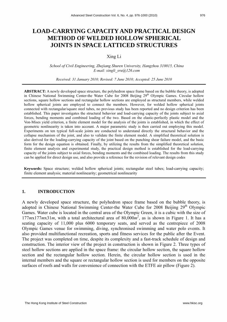
Figure 6. Dimensionless Axial Force – Bending Moment Correlation for Joints under Combined Compression and Bending (Note: S- Hollow Sphere; T-Rectangular Tube)
For joint under combined compression and bending, the correlation between axial compression and bending moment is the issue which we most concerned with. Only if making the correlation clear could we provide further evidence for the setup of practical calculation method. The axial compression N and bending moment M of joint when collapsed are made dimensionless using the relevant load carrying capacity Nmax and Mmax (both FE results). The dimensionless parameters
,N M are introduced as Expression (2).
.,maxmax M
M
N
NMN (2)
The correlation of dimensionless axial compression-bending moment is shown in Figure 6, where
,N M are the vertical and horizontal coordinates respectively. It may be found that the results data
are concentrated in the same curve for various joints with various eccentricities. That is to say, correlations of axial force and bending moment among different joints are consistent, and the correlations are independent of joint geometries, including sphere diameter and thickness, side length of tube. The property shows good agreement with that of WHSJ connected with circular pipe [5]. It is so important as to simplify, to a large extent, the calculation method of load carrying capacity of joint subject to combined axial force and bending moment.
ηN
M

Load-carrying Capacity and Practical Design Method of Welded Hollow Spherical Joints in Space Latticed Structures 982
3. EXPERIMENTAL STUDY 3.1 General of the Experiment Experiments on ten typical full-scale joints as are listed in Table 1 are conducted to understand directly the structural behavior and the collapse mechanism of the joint connected with rectangular tube, and to validate the finite element model, and also to provide the most reliable proofs for practical calculation method. Two types of welded hollow sphere are adopted, where Specimen 1 and Specimen 2 are identical in geometry with bending moments in different orientation acting on them. As the experiment is carried out primarily to investigate the collapse mechanics of joints, and meanwhile the thickness of steel tube has little influence on joint load carrying capacity, steel tubes with larger wall thickness (steel tube geometries: 150 mm×100 mm×16 mm, 200 mm×200mm×
16mm, 300 mm×200mm×22mm, 300mm×300mm×22mm, welded with four steel plates) are adopted to assure that the steel tubes would not collapse prior to the sphere. Four full-scale specimens are load with different eccentricities, where Specimen 3 and 5 is loaded with no eccentricity, i.e., axial compression. As experiment with infinite eccentricity is impossible to perform in the laboratory, pure bending loading test is not carried out here. Experiment is conducted with 500-ton compression testing machine in Civil Engineering Testing Center of Zhejiang University. Overall view of the experimental setup is shown in Figure 7. Schematic loading and testing station are shown in Figure 8. Various eccentricities are produced by changing the loading position on the specimen. Rigid box beams are welded to both ends of the specimen to ensure that the combined axial force and bending moment acting on the sphere are accurately simulated by eccentric loading on the box beams. Strain rosettes are arranged on the surface of sphere to measure the spherical outside strains, and strain gauges are arranged longitudinally on the tube surface to verify whether the loads are centrally directed and check the eccentricities. In addition, the dial indicators are used to measure displacements in various positions of the specimen.
Figure 7. Overall View of the Experiment

983 Xing Li
Table 1. Specimen Geometries and Summary of Experimental Results
Fy(kN) Fs/Fy Specimen No.
Sphere Dxt (mm×mm)
Tube axb (mm×mm)
Momentdirection
e (mm)
Fs
(kN) e=0 0e e=0 0e
1 D400×14 150×100 Dir.1 160 240 251 200 0.96 1.22 D400×14 150×100 Dir.2 160 282 294 256 0.96 1.103 D400×14 200×200 Dir.3 0 1910 1846 – 1.03 – 4 D400×14 200×200 Dir.4 160 760 763 661 0.996 1.155 D500×20 300×200 Dir.3 0 3500 3326 3308 1.05 1.066 D500×20 300×200 Dir.2 60 2260 2405 2216 0.92 1.027 D500×20 300×300 Dir.1 180 2095 2073 1853 1.01 1.138 D600×20 300×300 Dir.1 40 3080 3270 3006 0.94 1.029 D600×20 300×300 Dir.1 100 2400 2481 2251 0.97 1.0710 D600×20 300×300 Dir.4 30 3350 3410 3160 0.98 1.06
Note: Dir.1-along tube short side; Dir.2-along tube long side; Dir.3-along compression; Dir.4-along tube diagonal line.
Figure 8. Schematic of Loading and Instrumentation
3.2 Experimental Results and Analyzing Large numbers of data for strain and displacement are recorded during the testing. Herein, specimen 4 is only used for short as the illustrative example to elucidate the main testing results. Load-displacement curves for specimen 4 are shown in Figure 9 with θ as horizontal coordinates. The nominal angular displacement θ of joint under bending moment is estimated by the measured translational displacement with the dial indicator, provided that no bending deformation of steel tube is induced during loading. It could be observed from the curves that the displacement approximately increases linearly with the increase of load in the initial stage of loading, and the displacement subsequently increases nonlinearly. Plasticity in local area of the hollow sphere is meantime induced and the plastic area is enlarged gradually. The displacement increase rapidly with small increase of loading in the final stage, and continues to increase rapidly with the decrease of loading after collapse. As the experiment is conducted without servo loading, the curves during unloading are not recorded. Deformed shape of specimen 1 after failure is shown in Figure 10. It could be obviously observed from the photo that collapse of joint is chiefly induced by the large
Strain rosette
Dial indicator
Strain gauge

Load-carrying Capacity and Practical Design Method of Welded Hollow Spherical Joints in Space Latticed Structures 984
plastic deformation in local compressive area of spherical wall where the steel tube and hollow sphere meet. Great concave deformation is very clear as is shown in the photo. The collapsed load of specimens is listed in Table 1, where e indicates the eccentricity, Fs indicates result from testing, and Fy indicates finite element result. Specimens are also simulated for finite element analyses. Perfect elasto-plastic stress-strain relation is adopted in the preceding parametric analyses, and herein, the practical stress-strain relation (stress stiffness stage included) obtained by the material testing is adopted for accurate simulation of the experiment. In addition, the eccentric load acting on the end of specimen is always parallel to the axis of the steel tube in the preceding parametric analyses, and the eccentricity keeps unchanged during loading, i.e., the bending moment acting on joint keeps unchanged. This is actually true in the practical engineering. Nevertheless, the eccentric load acting on the end of specimen is always vertically downwards during the experiment, and the eccentricity would increase with the increasing deflection, corresponding to an additional eccentricity introduced. Accordingly, the actual bending moment acting on joints increases constantly. Two kinds of simulations of loading for each specimen are carried out in order to take account of the influence of additional eccentricity in the finite element analysis. The eccentric load acting on specimen is made parallel to the axis of the steel tube in the first simulation (i.e. taking no additional eccentricity into account), and the specimen is loaded vertically downwards in the end for the second simulation (i.e. taking account of the additional eccentricity). Load-displacement curves for specimen 1 of two types of loading are shown in Figure 9. In the initial stage of loading, the deformation in specimen is small, and the two curves almost coincide. With increasing loading, large deformation is induced in specimen, and the effect of additional eccentricity becomes notable. Load carrying capacity of joint without regard to additional eccentricity is obvious higher than that with regard to additional eccentricity. Moreover, the FE load-displacement curve agrees well with the experimental results in the initial loading stage. With increasing loading, differences between two curves become larger and larger especially in the elasto-plastic stage. It is probably because elasto-plastic stress-strain relation adopted in finite element analysis is impracticable to be exactly equal to that of the tensile specimen in the testing. Two groups of FE collapse load of specimens are listed in Table 1. The additional eccentricity has little influence on joint under axial compression. For joint under combined axial compression and bending, load carrying capacity without regard to additional eccentricity is obviously improved, averagely by 15%.
Figure 9. Load-displacement Curves Figure 10. Deformed Shape of Specimen 1
for Specimen 4 after Failure It is shown in Table 1 that the FE collapse load of specimen is close to that from experiment. But, the experimental result is slightly larger than that from FE results of joint with regard to additional eccentricity. Main possible factors making the differences are as follows: (1) Fillet welds besides butt welds exist in the conjunction where the tube and the hollow sphere meet, whereas the effects are disregarded in the FE simulations; (2) The material strength of weld is normally higher than that of the parent material, whereas strengths of both types are regarded to be identical in FE analysis.
0
50
100
150
200
250
300
0 0.05 0.1 0.15 0.2
θ(rad)
Load
(kN
)
Test FE(e=0) FE(e≠0)

985 Xing Li
Furthermore, material properties of hollow sphere may vary during machining, and the testing instruments and measurements may also introduce certain errors, making differences between them. As a whole, the FE model established in the paper can present accurately structural property and collapsed load, thus be used for parametric analyses on a large scale. It should be pointed out that the additional eccentricity is supposed to be regarded, for accurate simulation of experimental condition, for joint subject to combined axial compression and bending (additional eccentricity disregarded for joint under axial compression). Additional eccentricity may be disregarded for parametric analysis of practical engineering. 4. SIMPLIFIED THEORETICAL SOLUTION 4.1 Simplified Theoretical Solution of Joint subject to Axial Compression It is indicated by the previous studies that ultimate collapse of WHSJ with circular pipe has the feature of punching shear failure [5]. The WHSJ with rectangular tube is addressed in the paper, of which stress distribution in the area where the tube and hollow sphere meet is even more complicated. It has been shown from stress analyses in Section 3 that ultimate collapse of joint of such type has also the feature of punching shear failure. Simplified theoretical solution in the paper is based accordingly on punching shear failure model. Shear stress in punching section may be assumed to be kf for hollow spherical joint (as is shown in Figure 11(a)) under axial compression, where, f is the design tensile strength of joint material, and k is a coefficient to be specially determined in Section 4.2. When side length of tube is less small, punching shear failure is greatly obvious. On basis of Von-Mises yield criterion, failure shear stress tends to be 3f , i.e., 31k ( 21k base on Tresca yield criterion). When side length of tube is quite large, especially identical in geometry to sphere diameter, tensile stress (or compressive stress) instead of shear stress will be dominant, and the value tends to be f. On ground of FE stress analysis, WHSJ with rectangular tube under axial compression yield originally in the corners, inducing plastic area, and plastic area are expanded gradually to the side. Expanding course of plasticity from the corners to the side centers is shown in Figure 11 (b). Figure 11 (c) shows the final stage of expanding plasticity with whole section permeated. The dimensionless parameters are introduced,
a
x ,
b
y ,
b
a (3)
where, a, b is the side length of rectangular tube; Δ is the aspect ratio of rectangular tube (a=b, square tube).In the expanding stage of plasticity, the relation between axial compression acting on joint and shear stress in punching section is given by:
2
1
2
14 ftdbftdakN (4)
where, t is the wall thickness of hollow sphere. In the final stage when plasticity expands to the whole area, the axial compression reaches its maximum value, in which varies from 1/2 to 0 and varies from 1/2 to 0.
tfbakNN )(2max (5)

Load-carrying Capacity and Practical Design Method of Welded Hollow Spherical Joints in Space Latticed Structures 986
(a) Joint under Axial Compression (b) Plastic Area Expansion (c) Final Stage of Plastic Expansion
Figure 11. Model for Simplified Theoretical Solution for Axial Force
4.2 Simplified Theoretical Solution of Joint subject to Combined Axial Compression and
Bending For joint under combined axial compression and bending, as is shown in Figure 12a (M acts in the plane where long side a of tube lies), the expanding course of shear stress in punching section may be divided into two stages. In the first stage, upward shear stress is induced in part area of the punching section which is numbered 1 and without shadow, as is shown in Figure 12b-1, while downward shear stress is induced in other part which is numbered 2 and with shadow. The boundary area of upward and downward shear stress depends on the ratio of axial compression and bending moment. Based on the force equilibrium in the first stage, bending moment M is resultant from the upward shear stress in Area 1 and downward shear stress in Area 2, and the remainder downward shear stress composes the axial compression N. the axial compression N and the bending moment M could be easily obtained by the definite integral of shear stress in punching section.
)2
1(4 batfkN (6)
2
1
24
bd
aktfM (7)
where, a is the long side length of rectangular tube in the plane where the moment acts, b is the out of plane length. When the ratio M/N of bending moment to axial compression increases, upward shear stress in Area 1 expands gradually from the corners to the side centers, till the shear stress in the side turns wholly upward, as is shown in Figure 12 b-2. This is the dividing line between the first and second stage. When the ratio M/N further increase, upward shear stress turns around the corner to adjacent side and expands to the side center, as is shown in Figure 12 c-1. Herein, the second stage is reached, and the relation between the resultant force N, M and the shear stress in punching section may be derived from the following expressions.
x
y
a
b
y x
b
a
x
y
a
b
xy
a
b
D
N
t

987 Xing Li
(a) Joint under Combined Axial Compression and Bending
b-1 b-2 c-1 c-2
(b) First Stage (c) Second Stage
Figure 12. Model for Simplified Theoretical Solution for Combined Axial Force and Bending Moment
atfkN 4 (8)
2
1
2
1
0 24
adabd
aktfM (9)
When dividing line lies in the middle of the section side, as in shown in Figure 12 c-2, the bending moment reaches its maximum value, namely pure bending without axial force.
1 1
2 2max 0 0
14 1
2 2
aM M ktf bd a ad abktf
(10)
The dimensionless parameters are introduced,
maxmax
,M
M
N
NMN (11)
In the first stage, the following expressions can be deduced from Eq. 5, 6, 7, 8, 10,
1
2
max
N
NN (12)
2
11
21
max
M
MM (13)
y
b
x y
x
b
y x
b
x
y
a
b b
1 y x
D
M
a
a a
2
N
aa

Load-carrying Capacity and Practical Design Method of Welded Hollow Spherical Joints in Space Latticed Structures 988
In the first stage, the following expressions can be deduced from Eq. 5, 8, 9, 10,
1
1
2
max
N
NN (14)
21
21
2
max
M
MM (15)
The relation between N and M may be derived from Eq. 12 ~ 15.
MN
MN
112
11
1
12
11
1
21
12
1
10
M
M
(16)
0
0.2
0.4
0.6
0.8
1
1.2
0 0.2 0.4 0.6 0.8 1 1.2S350×14T200×200 S400×14T150×100
S500×20T270×180 S500×20T300×200S500×18T300×210 S500×16T300×300
S550×16T300×300 S600×16T300×300S600×20T300×270 S600×20T300×400
S650×20T300×400 Design Figure 13. Dimensionless Axial Force – Bending Moment Correlation for Joints under Combined
Compression and Bending (Note: S- hollow Sphere; T-rectangular Tube)
It is indicated from Eq. 16 that, for hollow sphere joint under combined axial compression and bending in given aspect ratio Δ of tube, the load carrying capacity correlation between axial compression and bending moment can be expressed as a line combined with a parabolic curve with
)21(1 M as the dividing point. Dimensionless axial force–bending moment correlation for joints under combined compression and bending is shown in Figure 13, where the simplified theoretical solution is illustrated for 5.1 as example. Meanwhile, large numbers of FE results are also expressed in Figure 13. It can be found that results of the two show good agreement. In practice, when the ratio Δ varies in the common range, curves determined by Eq. 16 are nearly equal. The FE results for various ratios Δ are actually covered in Figure 13. The correlation of axial force-bending moment is proved theoretically to be independent of the geometric parameters of joint on the one hand, and on the other hand FE results are also proved to be rational. It can also be found from Eq. 16 and Figure 13 that the axial compression decreases with the increase of bending moment.
N
M
MN 10
71
7
4
21
1
M
)1(3
7
5
3MN

989 Xing Li
It is found out from Eq. 12, 13 that the relevant expression about should be primarily solved to obtain N , M in the first stage. Eq. 6 and Eq. 7 may be rewritten as:
ba
Nktf
42 (17)
abab
Mktf
2 (18)
Combined Eq. 17 and Eq. 18, expression about can be derived:
b
MN
b
MN
42
2
(19)
It is indicated in the above equation that is equal to 1/2 for M=0, and is equal to 0
for 2N M b . Thereby, the first stage is characterized by 2N M b . It is found out from Eq. 14, 15 that the relevant expression about should be primarily solved to obtain N , M in the second stage. Eq. 8 and Eq. 9 may be rewritten as:
a
Nktf
4 (20)
222 22
1 aaab
Mktf
(21)
Combined Eq. 20 and Eq. 21, expression about can be obtained:
4
1
2
12
Na
M
Na
M (22)
For joint under combined axial force N and bending moment M, it should primarily determine which stage the joint falls into based on N, M and side length b of tube. For bMN 2 , the joint
belongs to the first stage, and for bMN 2 , the joint belongs to the second stage. In the first stage, expression about is determined by Eq. 19, and the corresponding expressions about N , M are obtained accordingly by Eq. 12 and Eq. 13. In the second stage, expression about is determined by Eq. 22, and the corresponding expressions about N , M are obtained accordingly by Eq. 14 and Eq. 15. Finally, the load carrying capacity of joint may be determined based on the axial force:
tfbakN N )(2 (23) and may also be determined based on the bending moment:
abtfkM M
2
11 (24)

Load-carrying Capacity and Practical Design Method of Welded Hollow Spherical Joints in Space Latticed Structures 990
The two expressions are equivalent. The physical meanings of N , M are rather definite from Eq.
23 and 24, where N is the influence coefficient of axial force with regard to bending moment, and
M is the influence coefficient of bending moment with regard to axial force. 4.3 Simplified Theoretical Solution of Joint subject to Combined Axial Compression and
Biaxially Equivalent Bending For joint under combined axial compression and biaxially equivalent bending, the upward shear stress is induced in part area of the punching section (numbered 1 and without shadow, shown in Figure 14b-1) and spreads from the corner to the midpoints, while downward shear stress is induced in other part (numbered 2). The boundary area of upward and downward shear stress depends on the ratio of axial compression and bending moment. For case a=b, the equivalent moment M acts in the diagonal plane of the section. Based on the force equilibrium, bending moment M is resultant from the upward shear stress in Area 1 and downward shear stress in Area 2, and the remainder downward shear stress composes the axial compression N. The axial compression N and the bending moment M could be easily obtained by the definite integral of shear stress in punching section.
(a) (b) (c)
Figure 14. Model for Simplified Theoretical Solution for
Combined Axial Force and Biaxially Rquivalent Bending Moment
2
12
144 atfkdatfkN (25)
2222
1
4
3245sin)
2
1(4
tfaktfdakM (26)
For 1 2 , the upward shear stress is actually inexistent in Area 1 (shown in Figure 14a), while only the downward shear stress is induced in the section. The axial force reaches its maximum value, namely pure compression or pure tension without bending.
2
1
2
1max 44 atfkdatfkNN =’ (27)
For 1 2 , the dividing line of the upward and downward shear stress lies in the middle of the section side, as in shown in Figure 14c, and the length of Area 3 becomes zero. The bending moment reaches its maximum value, namely pure bending without axial force.
11
22 2 2 22
1max1
22
1 1 14 ( ) sin 45 2 2 2
2 2 2M M k a tf d k a tf k a tf
’ = (28)
a
b
y x
a
a a
b
2 a
a
yx
3
b
y x
M
a
a
1

991 Xing Li
Combining Eq. 25 and Eq. 27,
2
1
max
N
NN (29)
Combining Eq. 26 and Eq. 28,
2
max 4
3 M
MM (30)
The relation between N and M may be derived from Eq. 29, Eq. 30.
MN 1 (31)
It is indicated from the above equation that, for hollow sphere joint under combined axial compression and biaxially equivalent bending, the load carrying capacity correlation between axial compression and bending moment can be expressed as a parabolic curve, as is shown in Figure 15. Meanwhile, the results show good agreement with the obtained FE results. The correlation of axial force–bending moment is proved theoretically to be independent of the geometric parameters of joint on the one hand, and on the other hand FE results are also proved to be rational. It can also be found from Eq. 14 and Figure 15 that the axial compression decreases with the increase of bending moment.
Figure 15. Dimensionless Axial Force-Bending Moment Correlation for Joints under Combined Compression and Biaxially Equivalent Bending
It is found out from Eq. 29, Eq. 30 that the relevant expression about should be primarily solved to obtain N , M in the first stage. Eq. 4 and Eq. 5 may be rewritten as:
2
14
Nkatf (32)
From Eq. 26, the following equation can be obtained,
0
0.2
0.4
0.6
0.8
1
1.2
0 0.2 0.4 0.6 0.8 1 1.2
S350×14T200×200S500×16T250×250S600×16T300×300S600×20T300×300S700×30T300×300Simplified solution
N
M
Load-carrying Capacity and Practical Design Method of Welded Hollow Spherical Joints in Space Latticed Structures 992
2
4
32 a
Mkatf (33)
Combining Eq. 32, Eq. 33
04
322212
Na
M
Na
M (34)
Solving the above equation, can be obtained,
2
21
2
2
1
Na
M
Na
M (35)
For joint under combined axial force N and bending moment M acting in the diagonal plane of section, can be obtained by Eq. 35 when M, N and a are given. The corresponding expressions about N , M are obtained accordingly by Eq. 29 and Eq. 30. The load carrying capacity of joint may be determined based on the axial force:
atfkNN NN 4maxR (36)
and may also be determined based on the bending moment:
tfakMM MM2
maxR 2 (37)
The two expressions are equivalent. The physical meanings of N , M are the same with that
defined in the above expressions, where N is the influence coefficient of axial force with regard to
bending moment, and M is the influence coefficient of bending moment with regard to axial force. 5. PRACTICAL DESIGN METHOD FOR LOAD CARRYING CAPACITY The load carrying capacity of WHSJ with rectangular/square steel tube under combined axial compression and bending has been discussed based on the simplified theoretical solution, as is shown in Eq. 23 and Eq. 24. Load carrying capacity will be further evaluated in this section to establish the practical calculation method, with the FE analyses and experimental results. Calculation methods for axial compression and bending moment are established respectively, and calculation method for combined axial compression and bending is accordingly established. For consistency with the current specification for latticed shells [3] and design criterion of WHSJ with circular pipe under combined axial force and bending [5], load carrying capacity of joints under axial force is given by Eq. 5 in the following expression.
tfbaD
abBAN R )(2
(38)

993 Xing Li
The expression in the first bracket corresponds to the coefficient k discussed in Section 4.1. Similarly, load carrying capacity of joints under bending is given by Eq. 10 in the following expression.
abtfD
abBAM R
2
11'' (39)
In Eq. 38, 39, A,B, 'A , 'B are coefficients to be determined based on the FE and experimental results. For joint under axial force, load carrying capacity made dimensionless by tfba )(2 is used as
the vertical coordinate, while Dab as the horizontal coordinate. The correlation is shown in Figure 16 which is used to determined coefficients A, B. The lower envelop of FE results shown by the real line in Figure 16 is chosen as the design line for safety. The coefficients are then determined, A = 0.3,B = 0.57,for consistency with the design criterion of WHSJ with circular pipe [5]. Namely the design criterion is Dab57.03.0 . For tubes and hollow spheres in practical
engineering, Dab usually ranges from 0.25 to 0.60, and k ranges correspondingly from 0.44 to 0.64, which is equal to that determined by Mises or Tresca yield criterion. It is indicated that collapse of the type is characterized by shear punching failure.
0
0.1
0.2
0.3
0.4
0.5
0.6
0.7
0.8
0 0.1 0.2 0.3 0.4 0.5 0.6 0.7 0.8
FE
Design
Figure 16. Determination of Coefficients in Formula for Axial Force
For joint under pure bending, load carrying capacity made dimensionless by 1 0.5ab tf is
used as the vertical coordinate, and the correlation with Dab is shown in Figure 17 which is
used to determined coefficients A’, B’. It is found that design equation determined by A’= A = 0.3、B’ = B = 0.57 can also regard to be the lower envelop for FE results. In this way design equations of load carrying capacity are normalized and simplified for axial force and pure bending.
tfba
N
)(2
Dab

Load-carrying Capacity and Practical Design Method of Welded Hollow Spherical Joints in Space Latticed Structures 994
0
0.1
0.2
0.3
0.4
0.5
0.6
0.7
0.8
0 0.1 0.2 0.3 0.4 0.5 0.6 0.7 0.8
FE
Design
Figure 17. Determination of Coefficients in Formula for Bending Moment
For joint under combined axial force and bending moment, as is mentioned before, load carrying capacity of joint may be determined based on the axial force taking account of the corresponding influence coefficient N , and also on the bending moment taking account of M . The design
equation based on axial force is given in Eq. 40.
tfbaD
abBAN NR )(2
(40)
and design equation based on bending moment is given in Eq. 41.
abtfD
abBAM MR
2
11 (41)
The simplified theoretical solutions by Eq. 40 and Eq. 41 coincide in format with that by Eq. 23 and Eq. 24. The coefficients are also chosen as A = 0.3, B = 0.57. The FE load carrying capacity
based on axial force is made dimensionless by tfbaN )(2 , and the correlation with Dab is shown in Figure 18, in which N is determined by Eq. 12 or Eq. 14. It is found that design
equation determined by Dab57.03.0 is also applicable for the lower envelop of FE results.
0
0.1
0.2
0.3
0.4
0.5
0.6
0.7
0.8
0 0.1 0.2 0.3 0.4 0.5 0.6 0.7 0.8
FE
Design
Figure 18. Determination of Coefficients in Formula for
Combined Axial Force and bending moment
abtf
M
21
Dab
tfba
N
N )(2
Dab

995 Xing Li
Comparisons of collapsed load between the experimental results and the design formula are made, as is shown in Table 2. The safety factor in the design formula is about 1.47 which is smaller than that (about 1.6) specified in Chinese Specifications [JGJ 61-2003]. It has been shown from studies on WHSJ with circular pipe in Ref. [5] that the eccentricity would increase with the increasing deflection, corresponding to an additional eccentricity introduced. Namely, the actual collapsed bending moment acting on joints is larger than the designed value. When load carrying capacity is determined by the design formula, the influence coefficient M is obtained by the design bending moment. The influence coefficient is consequently larger, and the corresponding design load carrying capacity is higher. Load carrying capacity without regard to additional eccentricity is obviously larger than that with regard to additional eccentricity, improved averagely by 15%. The safety factor of experimental results in the paper for evaluation of proposed formula is smaller, where it is mainly caused by the inescapable additional eccentricity. As additional eccentricity is actually inexistent in practical engineering, design formula proposed in this paper is regarded to have the equivalent safety factor with that specified in the current specification [JGJ 61-2003].
Table 2. Evaluation of Proposed Formula
No. Sphere
(mm×mm) Tube
(mm×mm)
Test value (kN)
Design(kN)
Test/Design
1 D400×14 100×150 240 164 1.46 2 D400×14 150×100 282 210 1.34 3 D400×14 200×200 1910 1409 1.36 4 D400×14 200×200 760 533 1.36 5 D500×20 300×200 3500 2375 1.47 6 D500×20 300×200 2260 1662 1.36 7 D500×20 300×300 2095 1433 1.46 8 D600×20 300×300 3080 2272 1.36 9 D600×20 300×300 2400 1727 1.39 10 D600×20 300×300 3350 2500 1.34
In summary, practical calculation methods of load carrying capacity for WHSJ with rectangular tube are given in following expressions. For joint under axial force:
tfbaD
abNR )(2)57.03.0( (42)
For joint under pure bending:
abtfb
a
D
abM R
2
11)57.03.0( (43)
For joint under combined axial force and bending:
tfbaD
abN NR )(257.03.0
(based on axial force) (44)

Load-carrying Capacity and Practical Design Method of Welded Hollow Spherical Joints in Space Latticed Structures 996
abtfb
a
D
abM MR
2
1157.03.0 (based on bending moment) (45)
Where, D is the sphere diameter, t is sphere wall thickness, a, b is the side length of tube respectively (when a=b, the tube is the square tube ), f is the design tensile strength of steel,
,N M are the influence coefficients.
The design steps are as follows for joints under combined axial force and bending. 1) Determine which stage the joint falls into based on N, M and side length b of tube. For bMN 2 , the joint belongs to the first stage, and for bMN 2 , the joint belongs to the second stage. 2) In the first stage, expression about is determined by Eq. 19, and the corresponding expressions about N , M are obtained accordingly by Eq. 12 and Eq. 13. In the second stage, expression about is determined by Eq. 22, and the corresponding expressions about N , M are obtained accordingly by Eq. 14 and Eq. 15. 3) For given N , M , the load carrying capacity of joint may be determined based on the axial force by Eq. 44 or on the bending moment by Eq. 45. The FE analyses and experiment in this paper are aimed at WHSJ under uniaxial force. For WHSJ under biaxial or spatial force, preliminary FE results show that structural behavior of the type has little difference with the uniaxial joint. In addition, influence of stiffener is not taken into account in the paper. As no experimental results about influences of stiffener on load carrying capacity of joint under bending has been reported, and measures can hardly be taken to insure the stiffener fixed in the plane in which the bending moment acts, effect of stiffener may be disregarded for safety for joint under large bending moment. For the case where the axial force is dominant, the load carrying capacity can also be improved according to coefficients specified in Chinese Specifications [2, 3] (i.e., 1.4 for compressive sphere, and 1.1 for tensile sphere). 6. SIMPLIFIED DESIGN METHOD FOR COMBINED AXIAL FORCES AND
BIAXIAL BENDING MOMENTS The practical design method for load carrying capacity is presented for WHSJ under combined axial force and bending in this section. Whereas, biaxial bending moment usually acts on elements in the practical engineering, i.e., bending moments xM , yM act in two main planes, where xM acts
in xz plane, and yM acts in yz plane. The resultant bending moment of xM , yM ( Figure 19a) is given
by Eq. 46.
22yx MMM (46)
An angle of is staggered between the resultant moment and x-axial,
x
y
M
Marctan (47)
For 0 or 2 , it corresponds to the uniaxial bending. For biaxial bending, ranges randomly from 0 to 2 . For cases of the type, following the simplified design method is put forward: The

997 Xing Li
resultant bending moment M obtained by Eq. 46 acts in two main planes of tube respectively, as are shown in Figure 19b, Figure 19c. As load carrying capacity for joint under combined axial force and uniaxial bending is established in the previous study, practical load carrying capacity can be obtained by linear interpolation. Namely, solution to which ranges from 0 to 2 may be obtained by linear interpolation of the results for 0 and / 2 .
(a) Resultant of Biaxial Bending (b) Resultant Bending in xz Plane (c) Resultant Bending in yz Plane
Figure 19. Simplified Calculation for Biaxial Bending
For joint under combined axial force and biaxial bending, the load carrying capacity can also be determined based on the axial force or the bending moment. It is revealed from Eq. 44 that the influence coefficient N is only needed for interpolation when design of joint is based on the axial force. It is also revealed from Eq. 45 that not only the influence coefficient N but the expression ba 21 is needed for interpolation when design of joint is based on the bending moment. As
bending moment acts in different plane, expression ba 21 should be converted to 1 2b a .
Hereby joint design based on axial force is simpler. Detailed design steps based on axial force are presented as follows. 1)The resultant bending moment M is obtained by composition of xM , yM , from Eq. 46, 47.
2)The resultant moment M is supposed to act in xz plane (where the long side a of tube lies). Determine which stage the joint falls into based on N, M and side length a of tube. For bMN 2 , the joint belongs to the first stage, expression about is determined by Eq. 19, and the
corresponding expressions about N are obtained accordingly by Eq. 12. And for bMN 2 , the joint belongs to the second stage. Expression about is determined by Eq. 22, and the corresponding expressions about N are obtained accordingly by Eq. 14. It should be notified that
ba in above expressions (12,14,19,22). Herein, N is signified as Nx .
3)The resultant moment M is supposed to act in yz plane (where the long side b of tube lies). Determine which stage the joint falls into based on N, M and side length b of tube. For bMN 2 , the joint belongs to the first stage, expression about and N are obtained accordingly by Eq. 19
and 12. And for bMN 2 , the joint belongs to the second stage. Expressions about , N are
obtained accordingly by Eq. 22 and 14. It should be notified that b a in above expressions.
Herein, N is signified as Ny .
4)For given Nx , Ny , the influence coefficient N for biaxial bending can be obtained by the
interpolation formula, as is shown in Eq. 48.
NyNxN
22
2
(48)
xM N
bb M N xb M N θ
a
x
y
a a
y y
Load-carrying Capacity and Practical Design Method of Welded Hollow Spherical Joints in Space Latticed Structures 998
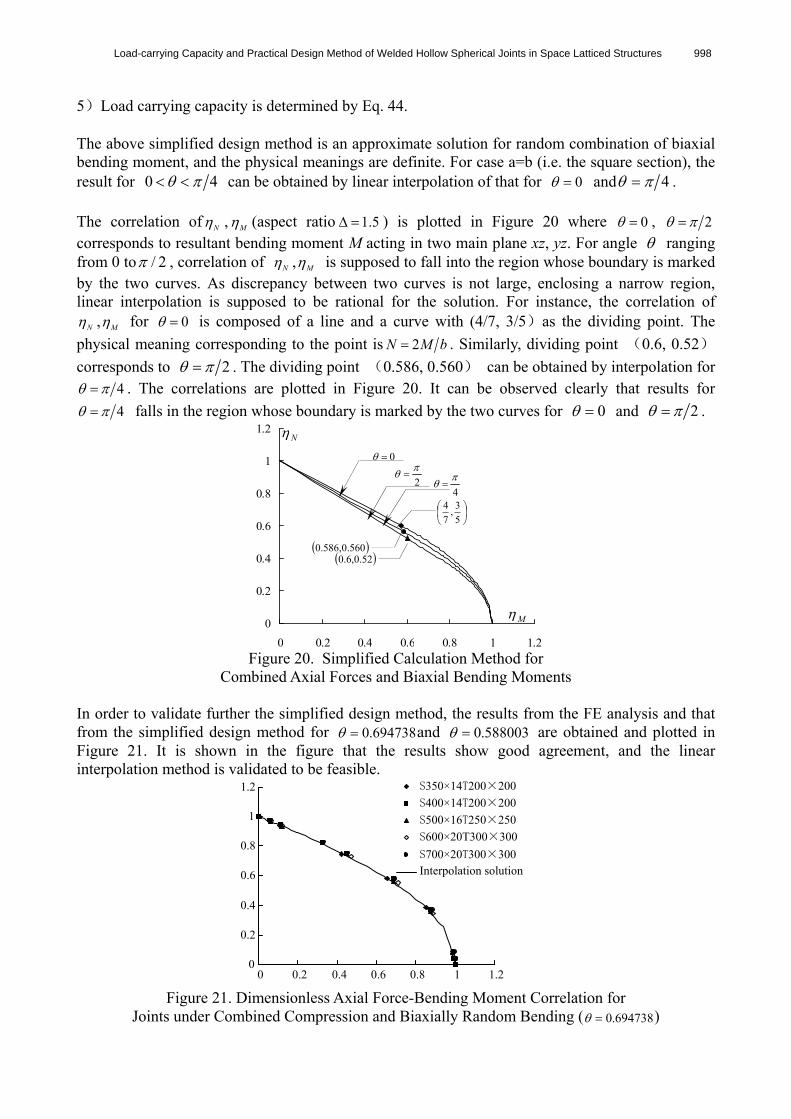
5)Load carrying capacity is determined by Eq. 44. The above simplified design method is an approximate solution for random combination of biaxial bending moment, and the physical meanings are definite. For case a=b (i.e. the square section), the result for 0 4 can be obtained by linear interpolation of that for 0 and 4 . The correlation of N , M (aspect ratio 5.1 ) is plotted in Figure 20 where 0 , 2 corresponds to resultant bending moment M acting in two main plane xz, yz. For angle ranging from 0 to / 2 , correlation of N , M is supposed to fall into the region whose boundary is marked by the two curves. As discrepancy between two curves is not large, enclosing a narrow region, linear interpolation is supposed to be rational for the solution. For instance, the correlation of
N , M for 0 is composed of a line and a curve with (4/7, 3/5)as the dividing point. The
physical meaning corresponding to the point is bMN 2 . Similarly, dividing point (0.6, 0.52)
corresponds to 2 . The dividing point (0.586, 0.560) can be obtained by interpolation for 4 . The correlations are plotted in Figure 20. It can be observed clearly that results for
4 falls in the region whose boundary is marked by the two curves for 0 and 2 .
0
0.2
0.4
0.6
0.8
1
1.2
0 0.2 0.4 0.6 0.8 1 1.2 Figure 20. Simplified Calculation Method for
Combined Axial Forces and Biaxial Bending Moments In order to validate further the simplified design method, the results from the FE analysis and that from the simplified design method for 694738.0 and 588003.0 are obtained and plotted in Figure 21. It is shown in the figure that the results show good agreement, and the linear interpolation method is validated to be feasible.
Figure 21. Dimensionless Axial Force-Bending Moment Correlation for
Joints under Combined Compression and Biaxially Random Bending ( 694738.0 )
0
0.2
0.4
0.6
0.8
1
1.2
0 0.2 0.4 0.6 0.8 1 1.2
S350×14T200×200
S400×14T200×200
S500×16T250×250
S600×20T300×300
S700×20T300×300Interpolation solution
M
N
5
3,
7
4
2
52.0,6.0
0
560.0,586.0
4

999 Xing Li
7. CONCLUSIONS 1)Based on the elastic-perfectly plastic model and the Von-Mises yield criterion, a finite element model for the analysis of these joints is established, in which the effect of geometric nonlinearity is taken into account. Great deal of FE parametric analyses are carried out by the model for WHSJ with rectangular tube under axial force, bending moment and combination of the two. The main factors which have influence on load carrying capacity are investigated. 2)Experiments on ten typical full-scale joints under axial force, bending moment and combination of the two are conducted to understand directly the structural behavior and the collapse mechanism of the joint connected with rectangular tube, and to validate the finite element model. 3)For joint subject to combined axial force and bending moment, FE analysis shows that axial force-bending moment correlation is independent of joint geometries, including sphere diameter and thickness, side length of tube. The property is further proved by the simplified theoretical solution. It is so important as to simplify, to a large extent, the calculation method of load carrying capacity. 4)Based on simplified theoretical solution and the FE, experimental results, calculation methods for axial compression, bending moment and combination of the two are established respectively. For joint subject to combined axial force and bending moment, the concept of influence coefficient is put forward for joint design based on axial force with respect to influence of bending moment (or on bending moment with respect to influence of axial force). The calculation method for influence coefficient is also presented. It is noteworthy that the above proposed design formulas are approximate evaluations for joint design, which are suggested to be used in the preliminary design stage for rough results. For more precise results, the finite element analyses are indispensable to joint design in the practical engineering. 5)For joint under combined axial force and biaxial bending, simplified calculation method is proposed in which load carrying capacity can be derived from linear interpolation of the results obtained by resultant bending moment acting in two main planes respectively. 6) In the present design code, design method is only provided for joint (circular tube with WHS) under axial force. The proposed design method has extended the application range of joint design to a great extent that is applicable to the load-carrying capacity of the joints subject to axial forces, bending moments and the combined loading. The results from the studies can be applied for direct design use, and also provide a reference for the revision of relevant design codes. ACKNOWLEDGMENT The author gratefully acknowledges the support of the Technological Project Foundation of Zhejiang Province (No. 2008C21149). The author also wishes to thank the anonymous reviewers for their constructive comments and suggestions.

Load-carrying Capacity and Practical Design Method of Welded Hollow Spherical Joints in Space Latticed Structures 1000
REFERENCES [1] GB 50017-2003, “Code for Design of Steel Structures”, Chinese Planning Press, Beijing
(in Chinese). [2] JGJ 7-91, “Specification for Design and Construction of Reticulated Structures”, China
Architecture & Building Press, Beijing, 1991 (in Chinese). [3] JGJ 61-2003, “Technical Specification for Latticed Shells”, China Architecture & Building
Press, Beijing, 2003. (in Chinese). [4] Han, Q.H. and Liu, X.L., “Ultimate Bearing Capacity of the Welded Hollow Spherical
Joints in Spatial Reticulated Structures”, Engineering Structures, 2004, Vol. 26, No. 2, pp.73-82.
[5] Dong, S.L., et al, “Load-carrying Capacity and Practical Calculation Method of Welded Hollow Spherical Joints Subject to Combined Axial Force and Bending Moment”, China Civil Engineering Journal, 2005, Vol. 38, No. 1, pp. 21-30 (in Chinese).
[6] Yuan, X.F., Pei, Z.L., et al, “Load-Carrying Capacity of Welded Hollow Spherical Joints Subject to Combined Planar Tri-Directional Axial Force and Bending Moment”, Journal of Zhejiang University (Engineering Science), 2007, Vol. 41, No. 9, pp.1436-42 (in Chinese).
[7] Lie, S.T., Lee, C.K. and Wong, S.M., “Model and Mesh Generation of Cracked Tubular Y-Joints”, Engineering Fracture Mechanics, 2003, Vol. 70, pp. 161-184.
[8] Lee, C.K., et al, “Numerical Models Verification of Cracked Tubular T, Y and K-Joints under Combined Loads”, Engineering Fracture Mechanics, 2005, Vol. 72, pp. 983-1009.
[9] Lee, M.M.K., “Strength, Stress and Fracture Analyses of Offshore Tubular Joints Using Finite Elements” Journal of Constructional Steel Research, 1999, Vol. 51, pp. 265-286.
[10] A. N’Diaye, et al, “Stress Concentration Factor Analysis for Welded, Notched Tubular T-joints under Combined Axial, Bending and Dynamic Loading”, International Journal of Fatigue, 2009, Vol. 31, pp. 367-374.
[11] Zhu Shi-zhe, et al, “Experimental Investigation of X-joint in Double-arch Structure”, Journal of Zhejiang University (Engineering Science), 2008, Vol. 42, No. 1, pp. 99-104 (in Chinese).
[12] Wang Ying-chuan, et al, “Analysis of Ultimate Bearing Capacity of Spatial Steel Tubular Joint”, Spatial Structures, 2007, Vol. 13, No. 4, pp. 25-27(in Chinese).