load-bearing external wall and partition wall kit
TRANSCRIPT

EAD 200207-00-0302
March 2020
LOAD-BEARING EXTERNAL WALL AND PARTITION WALL KIT
©2021

European Assessment Document – EAD 200207-00-0302 2/15
©EOTA 2021
The reference title and language for this EAD is English. The applicable rules of copyright refer to the document
elaborated in and published by EOTA.
This European Assessment Document (EAD) has been developed taking into account up-to-date technical and
scientific knowledge at the time of issue and is published in accordance with the relevant provisions of Regulation (EU)
No 305/2011 as a basis for the preparation and issuing of European Technical Assessments (ETA).
European Assessment Document – EAD 200207-00-0302 3/23
©EOTA 2021
Contents
1 Scope of the EAD ............................................................................................................................4
1.1 Description of the construction product 4
1.2 Information on the intended use(s) of the construction product 4 1.2.1 Intended use(s) ........................................................................................................................4 1.2.2 Working life/Durability ..............................................................................................................4
2 Essential characteristics and relevant assessment methods and criteria ...............................6
2.1 Essential characteristics of the product 6
2.2 Methods and criteria for assessing the performance of the product in relation to essential characteristics of the product 7
2.2.1 Axial compression strength ......................................................................................................7 2.2.2 Shear strength .........................................................................................................................7 2.2.3 Bending strength ......................................................................................................................7 2.2.4 Stiffness ...................................................................................................................................7 2.2.5 Reaction to fire .........................................................................................................................8 2.2.6 Resistance to fire .....................................................................................................................8 2.2.7 Propensity to undergo continuous smouldering ......................................................................8 2.2.8 Content, emission and/or release of dangerous substances ..................................................8 2.2.9 Water tightness ........................................................................................................................9 2.2.10 Water vapour permeability .......................................................................................................9 2.2.11 Air permeability ........................................................................................................................9 2.2.12 Airborne sound insulation ........................................................................................................9 2.2.13 Sound absorption .................................................................................................................. 10 2.2.14 Thermal transmittance .......................................................................................................... 10 2.2.15 Thermal inertia ...................................................................................................................... 10 2.2.16 Durability and long-term effects ............................................................................................ 11
3 ASSESSMENT AND VERIFICATION OF CONSTANCY OF PERFORMANCE ......................... 12
3.1 System(s) of assessment and verification of constancy of performance to be applied 12
3.2 Tasks of the manufacturer 12
4 Reference documents ................................................................................................................. 14
Annex A Principle drawings of the kit .................................................................................................... 16
Annex B Provisions for assessing propensity to undergo continuous smouldering ...................... 17
Annex C Axial compression strength .................................................................................................... 19
Annex D EN 13823: Reaction to fire tests for building products - Building products excluding floorings exposed to the thermal attack by a single burning item ..................................................... 21

European Assessment Document – EAD 200207-00-0302 4/23
©EOTA 2021
1 SCOPE OF THE EAD
1.1 Description of the construction product
The load-bearing external wall and partition wall kit consists of I-shaped studs made of a composite of galvanised steel, aluminium or stainless steel and hard-compressed stone wool to fit in a bottom and top channel, filled in with mineral wool assembled on site.
On the external flange of a stud, an external spacer made of stone wool is pre-mounted. Fasteners for masonry and light-weight cladding are part of the external spacers (exterior facing is not part of the kit). On the internal flange, vapour retarding OSB4 boards are mounted on site, providing racking strength and air tightness.
The studs are fixed to a bottom U-shaped steel channel by angle brackets, which are mounted to the substrate with bolts or screws. A similar top channel is fixed to the studs. All steel is protected against
corrosion by an inorganic zinc coating, at least grade Z275 according to EN 10346 1 or made from aluminium according to EN 755-1 or EN ISO 7599 or from stainless steel according to EN 10088.
Stone wool insulation is fitted between the flanges of the pre-manufactured studs as well as top and bottom channel without gaps, i.e. the stone wool is held in position by the steel members. Due to the mechanical properties of the medium density stone wool, the studs will be physically supported by the stone wool under extreme conditions.
Stone wool insulation is placed between the external spacers of the studs. This light-weight insulation minimizes thermal bridges and provides sufficient fire protection.
A service void is built up by internal spacers made of stone wool on the inside of the OSB layer. The service void is insulated with light-weight stone wool and finished by gypsum fibre boards (not part of the kit).
See annex A for an overview of the kit
The product is not covered by a harmonized technical specification.
Concerning product packaging, transport, storage, maintenance, replacement and repair it is the responsibility
of the manufacturer to undertake the appropriate measures and to advise his clients on the transport, storage,
maintenance, replacement and repair of the product as he considers necessary.
It is assumed that the product will be installed according to the manufacturer’s instructions or (in absence of
such instructions) according to the usual practice of the building professionals.
Relevant manufacturer’s stipulations having influence on the performance of the product covered by this
European Assessment Document, shall be considered for the determination of the performance and detailed
in the ETA.
1.2 Information on the intended use(s) of the construction product
1.2.1 Intended use(s)
Load-bearing external wall and partition wall kit in dwellings up to two and a half storeys in height.
1.2.2 Working life/Durability
The assessment methods included or referred to in this EAD have been written based on the manufacturer’s
request to take into account a working life of the load-bearing external wall and partition wall kit for the
intended use of 50 years. These provisions are based upon the current state of the art and the available
knowledge and experience.
1 All undated references to standards or to EADs in this document are to be understood as references to the dated versions listed
in clause 4
European Assessment Document – EAD 200207-00-0302 5/23
©EOTA 2021
When assessing the product, the intended use as foreseen by the manufacturer shall be taken into account.
The real working life may be, in normal use conditions, considerably longer without major degradation
affecting the basic requirements for works2.
The indications given as to the working life of the construction product cannot be interpreted as a guarantee neither given by the product manufacturer or his representative nor by EOTA when drafting this EAD nor by the Technical Assessment Body issuing an ETA based on this EAD, but are regarded only as a means for expressing the expected economically reasonable working life of the product.
2 The real working life of a product incorporated in a specific works depends on the environmental conditions to which that works
is subject, as well as on the particular conditions of the design, execution, use and maintenance of that works. Therefore, it
cannot be excluded that in certain cases the real working life of the product may also be shorter than referred above.

European Assessment Document – EAD 200207-00-0302 6/23
©EOTA 2021
2 ESSENTIAL CHARACTERISTICS AND RELEVANT ASSESSMENT METHODS AND CRITERIA
2.1 Essential characteristics of the product
Table 1 shows how the performance of the load-bearing external wall and partition wall kit is established in relation to the essential characteristics.
Table 2.1 Essential characteristics of the product and methods and criteria for assessing the performance of the product in relation to those essential characteristics
No Essential characteristic Method of assessment Type of expression of product
performance
Basic Requirement for Construction Works 1: Mechanical resistance and stability
1 Axial compression strength 2.2.1 Level
2 Shear strength 2.2.2 Level
3 Bending strength 2.2.3 Level
4 Stiffness 2.2.4 Level
Basic Requirement for Construction Works 2: Safety in case of fire
5 Reaction to fire 2.2.5 Class
6 Resistance to fire 2.2.6 Class
7 Propensity to undergo continuous smouldering
2.2.7 Description
Basic Requirement for Construction Works 3: Hygiene, health and the environment
8 Content, emission and/or release of dangerous substances
2.2.8 Level
9 Water tightness 2.2.9 Level
10 Water vapour permeability 2.2.10 Level
11 Air permeability 2.2.11 Level
Basic Requirement for Construction Works 5: Protection against noise
12 Airborne sound insulation 2.2.12 Level
13 Sound absorption 2.2.13 Level
Basic Works Requirement 6: Energy economy and heat retention
14 Thermal transmittance 2.2.14 Level
15 Thermal inertia 2.2.15 Level
Durability aspects
16 Durability and long-term effects
• Corrosion protection
2.2.16 Description
European Assessment Document – EAD 200207-00-0302 7/23
©EOTA 2021
2.2 Methods and criteria for assessing the performance of the product in relation to essential characteristics of the product
This chapter is intended to provide instructions for TABs. Therefore, the use of wordings such as “shall be stated in the ETA” or “it has to be given in the ETA” shall be understood only as such instructions for TABs on how results of assessments shall be presented in the ETA. Such wordings do not impose any obligations for the manufacturer and the TAB shall not carry out the assessment of the performance in relation to a given essential characteristic when the manufacturer does not wish to declare this performance in the Declaration of Performance.
Testing will be limited only to the essential characteristics which the manufacturer intends to declare. If for any components covered by harmonised standards or European Technical Assessments the manufacturer of the component has included the performance regarding the relevant characteristic in the Declaration of Performance, retesting of that component for issuing the ETA under the current EAD is not required.
2.2.1 Axial compression strength
The test is performed in accordance with annex C and the axial compressive strength is stated in the ETA.
2.2.2 Shear strength
The test is performed in accordance with described in section 10 in EN 408
Based on the load deflection curve determined in accordance with section 10.3 of EN 408, the following is calculated:
Calculation of shear strength as
Vmax [kN]= 0,5 x Fmax [kN]
where Fmax in kN is the maximum load applied at failure
The shear strength in kN is stated in the ETA.
2.2.3 Bending strength
Calculation of bending strength based on Fmax as found in 2.2.2 ‘Shear strength’ as
Mmax = 1/6 x Fmax x ℓ
where Fmax is the maximum load applied at failure
ℓ is the distance between support points
The bending strength is stated in the ETA
2.2.4 Stiffness
Calculation of stiffness based on load deflection curve as found in 2.2.2 ‘Shear strength’ as
E·I = 0,0177 x (F x ℓ³)/w
where F is an increment of load on the straight-line of the load deformation curve
ℓ is the distance between support points
w is the increment of the deformation corresponding to F
The stiffness is stated in the ETA.

European Assessment Document – EAD 200207-00-0302 8/23
©EOTA 2021
2.2.5 Reaction to fire
The load-bearing external wall and partition wall kit shall be tested, using the test method(s) relevant for the corresponding reaction to fire class, in order to be classified according to Delegated Regulation (EU) 2016/364 and EN 13501-1.
The classification shall be stated in the ETA.
Concerning mounting and fixing rules and extended application rules for reaction to fire, see Annex D.
When required by the manufacturer, the reaction to fire class according to Delegated Regulation (EU) 2016/364 and EN 13501-1 of components included in the kit shall be stated in the ETA.
Components covered by Decision 96/603/EC as amended by amendment 2000/605/EC for an A1 classification without testing
Components covered by another appropriate CWFT decision, so far the conditions set out in that decision are applicable for the use of the component in the kit covered by this EAD
The classes are given in the ETA
2.2.6 Resistance to fire
The load-bearing external wall and partition wall kit shall be classified according to EN 13501-2 and tested according to relevant methods corresponding to the relevant resistance to fire class. The class is given in the ETA
2.2.7 Propensity to undergo continuous smouldering
The propensity to undergo continuous smouldering of the stone wool and wood-based panels shall be
tested and assessed in accordance with EN 16733 and as specified in annex B.
In accordance with EN 16733:2016, clause 11, the ETA shall specify the following information, for the stone wool and the wood-based panels, depending on the outcome of the assessment:
− “The product does not show propensity to undergo continuous smouldering”; or
− “The product shows propensity to undergo continuous smouldering” or
− "Assessment of the propensity to undergo continuous smouldering is not possible".
2.2.8 Content, emission and/or release of dangerous substances
The performance of partition kits related to the emission and/or release and, where appropriate, the content
of dangerous substances will be assessed on the basis of the information provided by the manufacturer3 after identifying the release scenarios (in accordance with EOTA TR 034) taking into account the intended use of the product and the Member States where the manufacturer intends his product to be made available on the market. Purely inorganic boards, slabs or mats alone and purely inorganic kits with fasteners and frames made of uncoated steel does not have to be tested.
The intended release scenarios for this product and intended use with respect to dangerous substances for this product are:
IA2: Product with indirect contact to indoor air (e.g. covered products) but possible impact on
indoor air.
S/W2: Product with indirect contact to soil, ground- and surface water
3 The manufacturer may be asked to provide to the TAB the REACH related information which he must accompany the DoP with (cf.
Article 6(5) of Regulation (EU) No 305/2011). The manufacturer is not obliged:
− to provide the chemical constitution and composition of the product (or of constituents of the product) to the TAB, or
− to provide a written declaration to the TAB stating whether the product (or constituents of the product) contain(s) substances which are classified as dangerous according to Directive 67/548/EEC and Regulation (EC) No 1272/2008 and listed in the "Indicative list on dangerous substances" of the SGDS.
Any information provided by the manufacturer regarding the chemical composition of the products may not be distributed to EOTA or to TABs.

European Assessment Document – EAD 200207-00-0302 9/23
©EOTA 2021
2.2.8.1 SVOC and VOC
For the intended use covered by the release IA2 semi-volatile organic compounds (SVOC) and volatile organic compounds (VOC) are to be determined in accordance with EN 16516. The loading factor to be used for emission testing is determined in accordance with EN 16516.
Loading factors L in accordance with EN 16516, depending on the product type:
Loading factor [m2/m3]
Intended use
1,0 walls
0,05 small surfaces, e.g. door, window, heating system
0,007 very small surfaces, e.g. sealants
The preparation of the test specimen is performed by using all possible components of the kit (for the definition of the kit see clause 1.3) installed in accordance with the manufacturer's product installation instructions or (in absence of such instructions) the usual practice of installation.
Once the test specimen has been produced, as described above, it should immediately be placed in the emission test chamber or cell. This time is considered the starting time of the emission test.
The test results have to be reported for the relevant parameters (e.g. chamber size, temperature and relative humidity, air exchange rate, loading factor, size of test specimen, conditioning, production date, arrival date, test period, test result) after 3 and 28 days testing.
The relevant test results shall be expressed in [mg/m³] and stated in the ETA.
2.2.9 Water tightness
The water tightness under static pressure of the load-bearing external wall and partition wall kit shall be tested according to EN 12155.
The test begins with three pulses of 500 Pa before water spraying starts and then continues in sequence of pressures and times as of EN 12154/Table 1 until penetration of water is observed
The test pressure for which it has been applied is stated in the ETA.
The resistance of the load-bearing external wall and partition wall kit to driving rain under pulsating air pressure shall be tested according to EN 12865 procedure A according to table 1. One sample is tested. The test pressure for which it has been applied is stated in the ETA.
2.2.10 Water vapour permeability
The water vapour permeability of the kit is assessed by testing of the component in accordance with EN ISO 12572. In case the component is covered by a hEN or and ETA and bought from the market separately the value is taken from the Declaration of Performance of the component manufacturer. Alternatively, the tabulated values for the specified component can be derived from EN ISO 10456.
The water vapour permeability and the test/calculation conditions under which the value was determined for the relevant components shall be given in the ETA.
2.2.11 Air permeability
The air permeability of the load-bearing external wall and partition wall kit shall be tested according to EN 12114, Annex A. The test pressure in accordance with annex A of EN 12114 and the performance is stated in the ETA
2.2.12 Airborne sound insulation
Testing of load-bearing external wall and partition wall kit for airborne sound insulation is performed in a laboratory as described in EN ISO 10140-2 section 6.2 (large test area).

European Assessment Document – EAD 200207-00-0302 10/23
©EOTA 2021
The abovementioned test applies to the assembled kit, meaning that all relevant components shall be included in the test specimen. The size of the test specimen is determined by the full-size test opening of the test facility.
The measured airborne sound insulation is expressed as a single number rating, Rw(C; Ctr), in accordance with EN ISO 717-1 and given in the ETA.
2.2.13 Sound absorption
Testing of the sound absorption coefficient of materials is performed as described in EN ISO 354.
The measured sound absorption is expressed as a single number rating in accordance with EN ISO 11654 and given in the ETA.
2.2.14 Thermal transmittance
Calculation of the thermal insulation characteristics is performed as described in EN ISO 6946 and EN ISO 10211.
Testing of thermal resistance is performed as described in:
EN ISO 8990, EN 12667, EN 12939, EN 12664
The calculated or measured value of the thermal resistance (R-value) in m2 K/W is given in the ETA together with an indication of which method was used, the composition of partition and if calculation was used, the calculation process and the validation method of calculated results
The effect of any areas of thermal bridging shall be included as a weighted area resultant for the total system based on its R-value.
2.2.15 Thermal inertia
To make it possible to calculate the thermal inertia I of the load-bearing external wall and partition wall kit, information on the following properties of the partition shall be given (alternatively, 1-3-4 or 2-3-5):
1. total mass per unit area (in kg/m2) for the assembled kit M 2. density of materials used ρ (in kg/m3) 3. heat capacity of materials used H (in J/kg K) 4. thermal transmittance of materials used U (in W/m2 K) 5. thermal conductivity λ (in W/(m K)).
The information given on the total mass per unit area, the density of materials, the heat capacity of materials and the thermal transmittance of materials is given in the ETA.
The total thermal inertia is calculated in accordance with:
I = √(U H M) or I = √(λ H ρ ,) depending on whether it is a homogeneous load-bearing external wall and
partition wall kit (in the sense of a single material) or a partition made of different material layers.
I is expressed in [J m−2 K−1 s−1/2] and shall be given in the ETA.
If the partition section is a package made of different material layers, see Appendix A of EN ISO 13786 for a simplified calculation method of the heat capacity per unit area is used:
χ = ρ d c
where
Χ is the heat capacity per unit area in J/(m2 K)
ρ is the density of the material in the layer in kg/m3
d is the thickness of the layer in m
c is the specific heat capacity in J/(kg·K)

European Assessment Document – EAD 200207-00-0302 11/23
©EOTA 2021
2.2.16 Durability and long-term effects
2.2.16.1 Corrosion resistance of steel parts
The corrosion protection of the kit components shall be described according to the appropriate EN standard (e.g. EN 10346 for continuously hot-dip coated steels).
The choice of steel, aluminium and stainless steel grade shall be described according to the appropriate EN standards (e.g. EN 10346 for continuously hot-dip coated steel, EN 755-1, EN ISO 7599 and EN 1999-1-1 for aluminium alloys, EN 10088-1 and EN 10088-2 for stainless steels).
The steel or aluminium grade and the respective corrosion protection shall be described in function of the field of application and the corrosivity of atmospheres defined in EN ISO 9223 (e.g. marine atmosphere, industrial atmosphere, etc.). In particularly aggressive atmospheres with extreme chemical pollution (e.g. desulphurization plants, chloride atmosphere), special measures of corrosion protection shall be foreseen.
If necessary, the performance deterioration caused by corrosion should also be stated in the ETA.

European Assessment Document – EAD 200207-00-0302 12/23
©EOTA 2021
3 ASSESSMENT AND VERIFICATION OF CONSTANCY OF PERFORMANCE
3.1 System(s) of assessment and verification of constancy of performance to be applied
For the products covered by this EAD the applicable European legal act is: Decision 2003/728/EC
The system is: 1
3.2 Tasks of the manufacturer
The cornerstones of the actions to be undertaken by the manufacturer of the load-bearing external wall and partition wall kit in the procedure of assessment and verification of constancy of performance are laid down in Table 3.1.
Table 3.1 Control plan for the manufacturer; cornerstones
No Subject/type of control Test or control
method Criteria, if any
Minimum number of samples
Minimum frequency of
control
Factory production control (FPC)
2 Material Supplier
certificates Specified in control plan
Testing is not required
Each delivery
3 Geometry (form and dimensions)
Supplier certificates
Specified in control plan
Testing is not required
Each delivery
4 Mechanical characteristics
According to 2.2.1-2.2.5
Specified in control plan
Testing is not required
Each delivery
5 Reaction to fire of components
According to 2.2.5
Specified in control plan
1 Every two years
6 Checks on production drawings of the kit
Visual Specified in control plan
1 Each delivery
7 Manufactured components – where relevant
Specified in control plan
Specified in control plan
1 Each delivery
8
Propensity to undergo continuous smouldering
Indirect tests (e. g. dimensions, density, mass loss etc.)
Specified in control plan
1 Every batch
- Direct tests
Specified in control plan
1 Every two years
European Assessment Document – EAD 200207-00-0302 13/23
©EOTA 2021
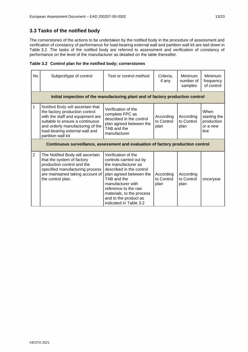
3.3 Tasks of the notified body
The cornerstones of the actions to be undertaken by the notified body in the procedure of assessment and verification of constancy of performance for load-bearing external wall and partition wall kit are laid down in Table 3.2. The tasks of the notified body are referred to assessment and verification of constancy of performance on the level of the manufacturer as detailed on the table thereafter.
Table 3.2 Control plan for the notified body; cornerstones
No Subject/type of control Test or control method Criteria, if any
Minimum number of samples
Minimum frequency of control
Initial inspection of the manufacturing plant and of factory production control
1 Notified Body will ascertain that the factory production control with the staff and equipment are suitable to ensure a continuous and orderly manufacturing of the load-bearing external wall and partition wall kit
Verification of the complete FPC as described in the control plan agreed between the TAB and the manufacturer
According to Control plan
According to Control plan
When starting the production or a new line
Continuous surveillance, assessment and evaluation of factory production control
2 The Notified Body will ascertain that the system of factory production control and the specified manufacturing process are maintained taking account of the control plan.
Verification of the controls carried out by the manufacturer as described in the control plan agreed between the TAB and the manufacturer with reference to the raw materials, to the process and to the product as indicated in Table 3.2
According to Control plan
According to Control plan
once/year

European Assessment Document – EAD 200207-00-0302 14/23
©EOTA 2021
4 REFERENCE DOCUMENTS
EN 10346:2015 Continuously hot-dip coated steel flat products for cold forming – Technical
delivery conditions EN 408+A1:2012 Timber structures – Structural timber and glued laminated timber – Determination
of some physical and mechanical properties EN 13501-1:2018 Fire classification of construction products and building elements – Part 1:
Classification using data from reaction to fire tests EN 13501-2:2016 Fire classification of construction products and building elements – Part 2:
Classification using data from fire resistance tests, excluding ventilation services EN 16516:2017 Construction products – Assessment of release of dangerous substances –
Determination of emissions into indoor air EN 12155:2000 Curtain walling – Watertightness – Laboratory test under static pressure EN 12154:2000 Curtain walling – Watertightness – Performance requirements and classification EN 12865:2001 Hygrothermal performance of building components and building elements –
Determination of the resistance of external wall systems to driving rain under pulsating air pressure
EN ISO 10456:2008 Building materials and products – Hygrothermal properties -Tabulated design
values and procedures for determining declared and design thermal values EN ISO 12572:2016 Hygrothermal performance of building materials and products – Determination of
water vapour transmission properties – Cup method EN 12114:2000 Thermal performance of buildings – Air permeability of building components and
building elements – Laboratory test method EN ISO 10140-2:2010 Acoustics – Laboratory measurement of sound insulation of building elements –
Part 2: Measurement of airborne sound insulation EN ISO 717-1:2013 Acoustics – Rating of sound insulation in buildings and of building elements –
Part 1: Airborne sound insulation EN ISO 354:2003 Acoustics – Measurement of sound absorption in a reverberation room EN ISO 11654:1997 Acoustics – Sound absorbers for use in buildings – Rating of sound absorption EN ISO 6946:2017 Building components and building elements – Thermal resistance and thermal
transmittance – Calculation method EN ISO 10211:2017 Thermal bridges in building construction – Heat flows and surface temperatures
– Detailed calculations (ISO 10211:2017) EN ISO 8990:1997 Thermal insulation – Determination of steady-state thermal transmission
properties – Calibrated and guarded hot box EN 12667:2001 Thermal performance of building materials and products – Determination of
thermal resistance by means of guarded hot plate and heat flow meter methods – Products of high and medium thermal resistance
EN 12939:2001 Thermal performance of building materials and products – Determination of
thermal resistance by means of guarded hot plate and heat flow meter methods – Thick products of high and medium thermal resistance
EN ISO 10211:2017 Thermal bridges in building construction – Heat flows and surface temperatures
– Detailed calculations
European Assessment Document – EAD 200207-00-0302 15/23
©EOTA 2021
EN 12664:2001 Thermal performance of building materials and products – Determination of
thermal resistance by means of guarded hot plate and heat flow meter methods – Dry and moist products of medium and low thermal resistance
EN 10346:2015 Continuously hot-dip coated steel flat products – Technical delivery conditions. EN 755-1:2016 Aluminium and aluminium alloys – Extruded rod/bar, tube and profiles -Part 1:
Technical conditions for inspection and delivery., EN 10088-1:2014 Stainless steels – Part 1: List of stainless steels. EN 10088-2:2014 Stainless steels – Part 2: Technical delivery conditions for sheet/plate and strip
of corrosion resisting steels for construction purposes. EN ISO 7599:2018 Anodizing of aluminium and its alloys – Method for specifying decorative and
protective anodic oxidation coatings on aluminium EN ISO 9223:2012 Corrosion of metals and alloys – Corrosivity of atmospheres - Classification,
determination and estimation EN 16733:2016 Reaction to fire tests for building products – Determination of a building product's
propensity to undergo continuous smouldering

European Assessment Document – EAD 200207-00-0302 16/23
©EOTA 2021
• I-shaped studs made of a
composite of galvanized steel
and hard-compressed stone wool
• Insulation
• Spacer
• OSB boards
• U-shaped steel channel
ANNEX A PRINCIPLE DRAWINGS OF THE KIT

European Assessment Document – EAD 200207-00-0302 17/23
©EOTA 2021
ANNEX B PROVISIONS FOR ASSESSING PROPENSITY TO UNDERGO CONTINUOUS SMOULDERING
B.1 Provisions for factory-made products made of mineral wool
B.1.1 Sample taking
In addition to EN 16733, the following conditions and parameters shall be considered when performing sampling and preparing test samples:
- the product-variations of a product family (as defined by a certain combination of raw materials and other additives and produced in a certain production process);
- the product or product variant with the highest organic content (in percentage per mass), determined according to EN 13820;
- the product or product variant with the highest density as well as a density of about 100 kg/m³ (± 15 %); if the highest density is lower than 115 kg/m³, then only the product or product variant with the highest density. (density determined in accordance with EN 1602);
- the product or product variant with the highest thickness. If the highest thickness is greater than 100 mm, then the specimen thickness shall be reduced from the reverse (non-exposed) side to the maximum testable thickness of about 100 mm. (thickness determined in accordance with EN 823 on at least three specimens).
- each different produced fibre orientation, i.e. lengthwise and crosswise to the length direction of the specimen as well as perpendicular to the surface of the specimen front side;
- without any facings, coatings (or similar) – existing facings or coatings shall be removed when preparing the test specimens.
B.1.2 Preparation of test specimen
The tests shall be done on free-hanging specimens without consideration of the intended end-use conditions, because propensity to undergo continuous smouldering is hardly affected by end-use conditions, and without any joints (see further).
B.1.3 Extended application of test results
The test results considering the aforementioned parameters are also valid for products:
- of the same defined product- family,
- with lower organic content,
- with all lower densities,
- with lower thickness and also with higher thickness when 100 mm thick specimens were tested,
- with all fibre orientations,
- with any facings or coatings and
- for any end-use conditions.
B.2 Provisions for wood-based boards / panels
B.2.1 Sample taking
In addition to EN 16733, the following conditions and parameters shall be considered when performing sampling and preparing test samples:
− product-variations of a product family (as defined by a certain combination of raw material, e. g. binder, additives, wood type of the wood shapes / wood fibres etc., and produced in a certain production process);
− the product or product variant with the highest as well as the lowest density of the wood-based board / panel, determined by tests according to EN 323;
− the product or product variant with the highest thickness of the wood-based board / panel, determined by tests according to EN 823 on at least three specimens;

European Assessment Document – EAD 200207-00-0302 18/23
©EOTA 2021
− each different produced shape / fibre orientation (i. e. lengthwise and crosswise to the length direction of the specimen);
− without any external non-substantial facings, coatings or suchlike – existing external non-substantial facings or coatings shall be removed when preparing the test specimens
B2.2 Preparation of tests specimens
The tests shall be done without consideration of the intended end-use conditions, because propensity to undergo continuous smouldering is hardly affected by end-use conditions. If the paragraph 6.2.5 of EN 16733 applies, a permanent contact between the pieces shall be assured.
B.2.3 Extended application of test results
The results of tests considering the aforementioned parameters in fully are also valid for products:
− of the same defined product-family ,
− with all densities of wood-based boards / panels between those evaluated,
− with lower thickness of wood-based boards / panels and also with higher thickness when 100 mm thick specimens were tested,
− with all shape / fibre orientations, if all relevant orientations had been tested,
− with any external non-substantial facings or coatings or suchlike and
− for any end-use conditions.

European Assessment Document – EAD 200207-00-0302 19/23
©EOTA 2021
ANNEX C AXIAL COMPRESSION STRENGTH
Principle
The test method given below is to assess the axial compression strength of the wall kit.
In the test, the load-bearing component of the wall kit is placed vertically and compressed to determine axial deformation and lateral deflection, and thus the axial load-bearing capacity of the kit.
Test apparatus
The apparatus shall be assembled as shown below (figure C.1) and shall be in accordance with the detailed specifications as set out below, or equivalent.
Meters monitoring compression load and axial deformation shall be attached to ends of the sample. Deflection meters shall be fixed to the sides of the sample, monitoring deflections in both axes at centre height of the sample.
Conditioning and test conditions
The sample conditioning shall be recorded. The conditioning period shall respect the kinds of materials used.
The test shall be carried out in laboratory circumstances, at a temperature of (23 5) °C, where required.
Test assembly
The sample assembly shall be mounted in accordance with the manufacturer’s installation specifications, with regard to the intended use, so that the test assembly corresponds as much as possible with the end-use conditions.
The length of test specimen corresponds to the intended height of the wall.
Number of tests
The test shall be carried out on at least ten samples for each length.
Figure C.1

European Assessment Document – EAD 200207-00-0302 20/23
©EOTA 2021
Test procedure
The sample shall be tested as a column, having a flat end at the bottom. Compressive loads shall be applied to a steel plate covering the upper end of the assembly. The load is applied uniformly along a line parallel to the sample as a concentrated load on a steel plate with dimensions suitable for the size of the sample.
Load rate: 0,1 kN/s (load depended, to make the various lengths of the test specimen comparable)
Attach a compression meter to the end of the sample or to the steel plate, to measure the shortening of the sample. Record the readings continuously, to the nearest 0,01 mm.
Attach two deflection meters, one in each direction of the sample to monitor dx and dy (see figure C.1). Record the readings continuously, to the nearest 0,1 mm.
The test is performed until failure load.
Deformation measurements:
• Axially
• dx, horizontally in x-axis at centre height
• dy, horizontally in y-axis at centre height
Expression of test results
Deformation
Calculate the shortening under each load as the difference between the reading of the meter when the load is applied and the initial reading.
Lateral deflection
Calculate the lateral deflection under each load for each deflection meter as the difference between the reading of the deflection meter when the load is applied and the initial reading.
General
Record the maximum load for each sample and report the results of load-deformation and load-deflection measurements in the form of a graph.
Test report
The test report shall include at least the following information:
a. the name of the testing laboratory b. the name of the manufacturer c. date of the test d. description of the test instruments e. description of the product tested f. description of conditioning and preparation of the sample (if any) g. the speed of applying the load h. description of test conditions (temperature and RH) i. results of the test (deflection and corresponding loads), including a description of damages
during the test and the reason for terminating the test

European Assessment Document – EAD 200207-00-0302 21/23
©EOTA 2021
ANNEX D EN 13823: REACTION TO FIRE TESTS FOR BUILDING PRODUCTS - BUILDING PRODUCTS EXCLUDING FLOORINGS EXPOSED TO THE THERMAL ATTACK BY A SINGLE BURNING ITEM
Mounting and fixing provisions
D.1 Terminology
Module:
A module in the context of this Annex is a sample of the kit fully reflecting all main components (e.g. frame, insulation and fasteners) in the kit cut to fit the size of the test rig. Components made for openings in the partition kit are not part of the module.
Extended application:
The outcome of a process (involving the application of defined rules that may incorporate calculation procedures) that predicts, for a variation of a product property and/or its intended use application(s), a test result on the basis of one or more tests to the same test standard.
D.2 Mounting and fixing in accordance with EN 13823
D.2.1 Dimensions of the test rig
The test rig consists of a corner with a long (1,0 m) and a short (0,5 m) wing. The long wing consists of 2 modules, with one vertical and one horizontal module-to-module joint in between. All modules shall be tested vertically. The dimensions of the specimens shall be:
Assembly dimensions (mm – nominally)
Length Height
Short wing 495 1500
Long wing (see figure D1)
200 + t 1500
800 - t 1500
Where t = thickness of the kit
D.2.2 Test specimen
The load-bearing external wall and partition wall kit shall be mounted and fixed according to EN 13823.
The test specimen shall fully represent all the envisaged components in the end use condition as specified by the applicant.
The assembly including corner and joint details shall be as specified by the applicant and in accordance with the end use conditions. Where several corner and jointing materials/profiles are foreseen, possible extended application rules may apply.
The largest frame thickness (perpendicular to the face) envisaged shall be used in the test. Test performed on timber framework also apply for metal framework.
Where relevant, the insulation material used shall be as specified by the applicant and represent end use conditions.
The type and dimensions of materials and products used, the dimensions and location of possible fixings etc. shall be recorded in the test report and described in the classification report.
The manner in which the product is tested, and the number of different tests conducted, has a direct consequence upon the scope of the applicability of the classification(s) to potential variations in product properties and the range of end use conditions that may be adopted in practice (see also clause D.3).
European Assessment Document – EAD 200207-00-0302 22/23
©EOTA 2021
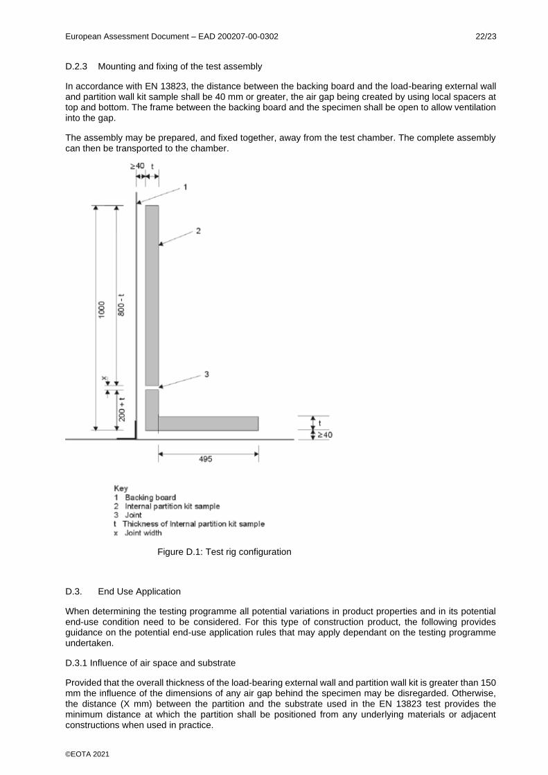
D.2.3 Mounting and fixing of the test assembly
In accordance with EN 13823, the distance between the backing board and the load-bearing external wall and partition wall kit sample shall be 40 mm or greater, the air gap being created by using local spacers at top and bottom. The frame between the backing board and the specimen shall be open to allow ventilation into the gap.
The assembly may be prepared, and fixed together, away from the test chamber. The complete assembly can then be transported to the chamber.
Figure D.1: Test rig configuration
D.3. End Use Application
When determining the testing programme all potential variations in product properties and in its potential end-use condition need to be considered. For this type of construction product, the following provides guidance on the potential end-use application rules that may apply dependant on the testing programme undertaken.
D.3.1 Influence of air space and substrate
Provided that the overall thickness of the load-bearing external wall and partition wall kit is greater than 150 mm the influence of the dimensions of any air gap behind the specimen may be disregarded. Otherwise, the distance (X mm) between the partition and the substrate used in the EN 13823 test provides the minimum distance at which the partition shall be positioned from any underlying materials or adjacent constructions when used in practice.
European Assessment Document – EAD 200207-00-0302 23/23
©EOTA 2021
The material forming the opposite face of the air space behind the partition in the EN 13823 test determines the type of element in front of which the load-bearing external wall and partition wall kit can be used.
If the load-bearing external wall and partition wall kit was tested in front of particleboard, the partition can be used in front of any wood structure or any A2 or A1 product. If the partition was tested in front of gypsum plasterboard the partition can be used only in front of any A2 or A1 product. If the partition was tested in front of calcium silicate board the partition can be used only in front of any A2 or A1 product except plasterboard (for further guidance see EN 13238).
D.3.2 Influence of insulation product
If the load-bearing external wall and partition wall kit incorporates an insulation material that is of Class A2 or lower than the influence of any changes in thickness or density of the insulation on the performance of the partition shall be determined. Extended application rules shall apply. If the insulation material is of Class A1, then the density and thickness may be increased without influence on the scope of the classification of the partition, as long as the insulation material is class A1.
If mineral wool is used as insulation material, it shall be the standard mineral wool as indicated in EN 13238. The result is then applicable to all insulation products of class A1.
G.3.3 Influence of surface finishes
Possible extended application rules shall apply, e.g. by grouping facings/coatings into families. Any classification scope appropriate to the surface finish may be appropriate to the partition, provided that the partition constructional detail (primarily the nature of the lining boards and insulation product) is covered by the scope of classification for the surface finish.
D.3.4 Influence of joints
The influence of joints may be dealt with using extended application rules.
Where a national regulation exists, a separate additional classification shall be provided for any material included as a jointing material or cover strip. This may not be required to have the same classification as the partition surface itself, dependent upon the national requirements.
D.3.6 General note
If different classifications are obtained when investigating the influence of variation in product properties or end use application, additional testing shall be conducted to redefine the product family to which any single classification applies.