lo w-acceleration solid-propellant rocket ignition … aeronautics and space administration...
TRANSCRIPT

N A T I O N A L A E R O N A U T I C S A N D S P A C E A D M I N I S T R A T I O N
Technical Memorandum 33-506
Lo w-Acceleration Solid-Propellant Rocket Ignition Study
Leon 0. Strand
J E T P R P P U L S I O N L A B O R A T O R Y
C A 1 I F O R N I A I N S T I T U.1 E 0 F T E C H N 0 L O G Y
P A S A D E N A , C A L I F O R N I A
December 1, 1971
https://ntrs.nasa.gov/search.jsp?R=19720005142 2018-05-14T00:50:33+00:00Z

N A T I O N A L A E R O N A U T I C S A N D S P A C E A D M I N I S T R A T I O N
Technical Memorandum 33-506
Lo w-Acceleration Solid-Propellant Rocket Ignition Study
Leon D. Strand
J E T P R O P U L S I O N L A B O R A T O R Y
C A L I F O R N I A I N S T I T U T E O F T E C H N O L O G Y
P A S A D E N A , C A L I F O R N I A
December 1, 1971

Prepared Under Contract N o . NAS 7-1 00 National Aeronautics and Space Administration

PREFACE
The work descr ibed i n this r epor t was per formed by the Propuls ion
Division of the J e t Propuls ion Laboratory.
J P L Technical Memorandum 33-506 ii i
ACKNOWLEDGMENT
The author i s indebted to M r . L. F o r d for p repa r ing the ign i te r and
m a i n m o t o r propellant c h a r g e s and Mr . A. R a s m u s s e n and Mr . S. Roche
f o r ass i s tance with the test f i r ings and instrumentat ion.
g ramming was p e r f o r m e d by M r . F. Rober t son of Lockheed Technical
Services .
Computer p ro -
iv JPL Technica l Memorandum 33-506

CONTENTS
I . Introduction . . . . . . . . . . . . . . . . . . . . . . . . . . . . . . . . . . . 1
I1 . Low-Acceleration Ignition System . . . . . . . . . . . . . . . . . . . . . 2
I11 . Tes t Sys tem . . . . . . . . . . . . . . . . . . . . . . . . . . . . . . . . . . . 3
IV . T e s t S e r i e s 1 . . . . . . . . . . . . . . . . . . . . . . . . . . . . . . . . . . 5
A . Tes t 1 . . . . . . . . . . . . . . . . . . . . . . . . . . . . . . . . . . . . 5
B . T e s t 2 . . . . . . . . . . . . . . . . . . . . . . . . . . . . . . . . . . . . 5
C . T e s t 3 . . . . . . . . . . . . . . . . . . . . . . . . . . . . . . . . . . . . 5
D . T e s t 4 . . . . . . . . . . . . . . . . . . . . . . . . . . . . . . . . . . . . 6
E . Tes t 5 . . . . . . . . . . . . . . . . . . . . . . . . . . . . . . . . . . . . 7
F . Tes t 6 . . . . . . . . . . . . . . . . . . . . . . . . . . . . . . . . . . . . 8
G . T e s t 7 . . . . . . . . . . . . . . . . . . . . . . . . . . . . . . . . . . . . 8
H . Tes t 8 . . . . . . . . . . . . . . . . . . . . . . . . . . . . . . . . . . . . 9
V . T e s t S e r i e s 2 . . . . . . . . . . . . . . . . . . . . . . . . . . . . . . . . . 11
VI . M a s s Balance P r o g r a m . . . . . . . . . . . . . . . . . . . . . . . . . . . 13
VI1 . Summary and Conclusions . . . . . . . . . . . . . . . . . . . . . . . . . . 14
Refe rences . . . . . . . . . . . . . . . . . . . . . . . . . . . . . . . . . . . . . . . . 16
TABLES
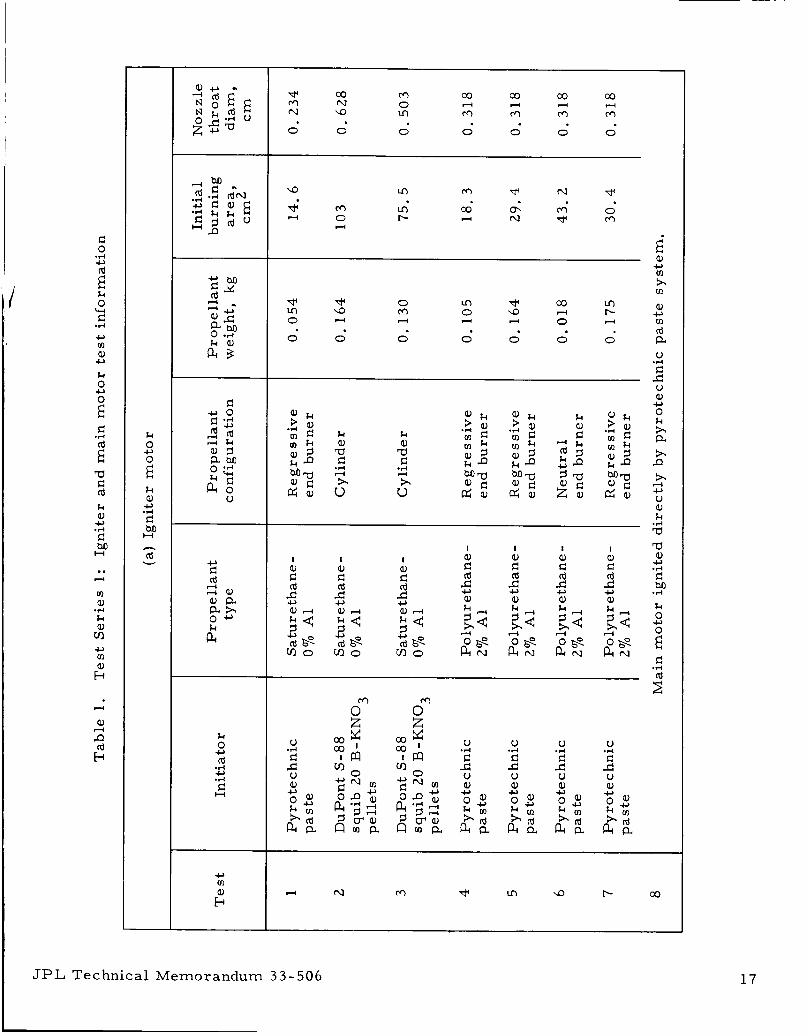
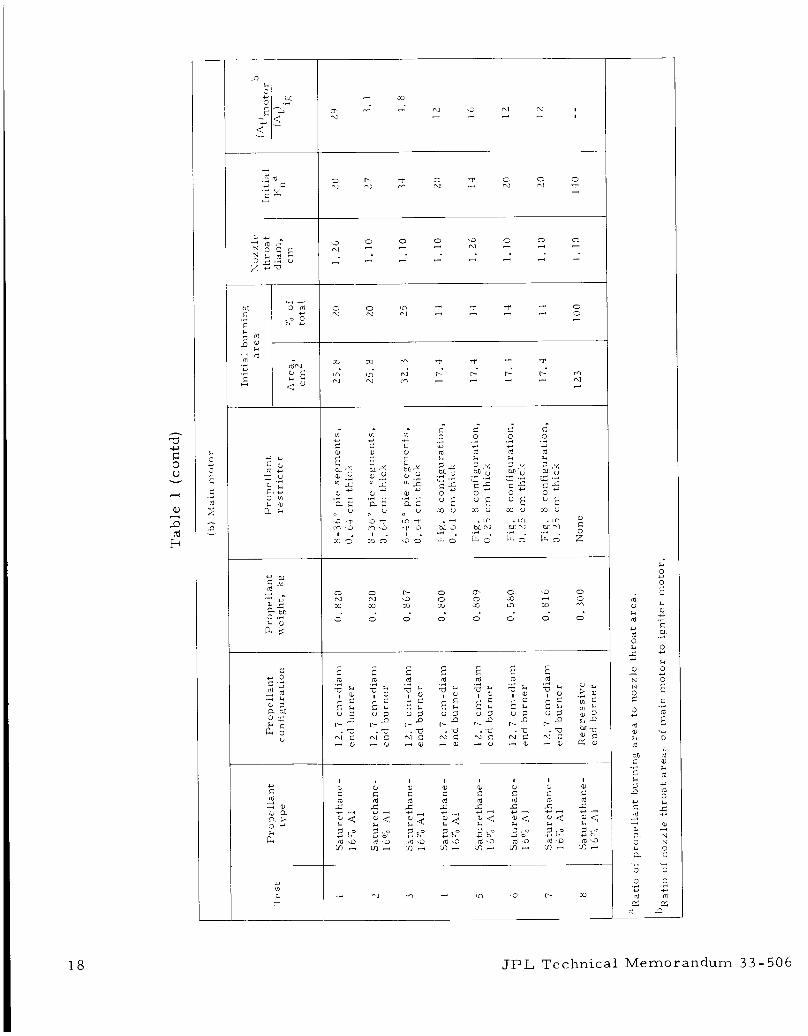
1 . Tes t Se r i e s 1: Igniter and main moto r t e s t in format ion . . . . . . . . . . . . . . . . . . . . . . . . . . . . . . . . . 17
2 . Tes t Se r i e s 1: Numer ica l tes t r e s u l t s . . . . . . . . . . . . . . 19
3 . Tes t Se r i e s 2: Tes t information and r e su l t s . . . . . . . . . . . 20
FIGURES
1 . Low-accelerat ion ignition concept . . . . . . . . . . . . . . . . . . 22
2 . Motor propel lant gasification rate m and nozzle exhaust flow ra te me vs motor c h a m % e r p r e s s u r e . with moto r propel lant burning a r e a Ab as independent p a r a m e t e r . . . . . . . . . . . . . . . . . . . . . . . . . 22
~ JPL Technical Memorandum 33-506 V

v i
CONTENTS (contd)
F IGURES (contd)
3 . L" v s m e a n chamber p r e s s u r e a t combustion extinction . . . . . . . . . . . . . . . . . . . . . . . . . . . . . . . . . 23
4. Test sys t em . . . . . . . . . . . . . . . . . . . . . . . . . . . . . . . . 24
5. Igniter end-burner propel lant charge , Tes t 4 . . . . . . . . . . 24
6. Test sys t em mounted on vacuum tank inlet pipe . . . . . . . . 25
7. Igniter motor and m a i n moto r t e s t p r e s s u r e - t i m e t r aces , Tes t 3 . . . . . . . . . . . . . . . . . . . . . . . . . . . . . . . 25
8. Main motor propellant r e s t r i c t e r configuration, Tes ts 4-7 . . . . . . . . . . . . . . . . . . . . . . . . . . . . . . . . . 26
9. Igniter mo to r and ma in moto r t e s t p r e s s u r e - t i m e t r a c e s , Tes t 4 . . . . . . . . . . . . . . . . . . . . . . . . . . . . . . 26
10. Igniter motor and ma in moto r t e s t p re s su re - t ime t r a c e s , Tes t 6 . . . . . . . . . . . . . . . . . . . . . . . . . . . . . . 27
11. Pos t - tes t view of m a i n moto r propel lant su r f ace , Test 6 . . . . . . . . . . . . . . . . . . . . . . . . . . . . . . . . . . . . 27
12. Cross-sec t ion of r e g r e s s i v e end-burner propellant charge, Tes ts 8, 10 , and 11 . . . . . . . . . . . . . . . . . . . . . 28
13. Igniter and ma in moto r p re s su re - t ime r e c o r d s , Tes t 16 . . . . . . . . . . . . . . . . . . . . . . . . . . . . . . . . . . . 28
14. Main motor mean p r e s s u r e at combustion extinction vs r a t io of igni ter motor to main moto r propellant m a s s addition r a t e s . . . . . . . . . . . . . . . . . . . . . . . . . . . 29
15. Sample calculation: m a i n moto r m a s s balance computer p r o g r a m , ma in moto r p r e s s u r e v s t i m e . . . . . . . . . . . . . . . . . . . . . . . . . . . . . . . . . . . 29
JPL Technical Memorandum 33-506

ABSTRACT
A study was conducted to develop a sol id-propel lant rocke t ign i te r
s y s t e m tha t would build up t h r u s t a t a control led r a t e of l e s s than 0. 2 g/s. The s y s t e m consis ted of a long burning, r eg res s ive burning, control led
flow igni te r and a n inhibited progress ive burning su r face i n the ma in
rocke t mo to r . The igni ter pe r fo rmed the dual r o l e of igniting under vac-
uum back-p res su re and low L* conditions the nonres t r ic ted port ion of the
propel lant and providing the m a s s addition n e c e s s a r y to sus ta in combus-
t ion unt i l the propellant burning a r e a had inc reased sufficiently to provide
a s table motor -chamber p r e s s u r e .
with exis t ing s m a l l t e s t mo to r hardware to (1) demonst ra te the feasibi l i ty
of the concept, (2) de te rmine the important p a r a m e t e r s governing the sys-
t e m , and (3 ) obtain design guidelines for future scaled-up moto r t e s t s .
A quas i - s teady-s ta te m a s s balance for the ignition s y s t e m was wr i t ten and
p r o g r a m m e d fo r u se as a moto r design tool.
Two s e r i e s of t e s t s w e r e conducted
JPL Technica l Memorandum 33-506 vii
I. INTRODUCTION
Typical solid-propellant mo to r s a r e ignited and build up th rus t v e r y
rapidly (5-50 g / s ) ; however, spacecraf t such a s those of the Mar ine r s e r i e s
cannot withstand high acce lera t ion t rans ien ts . The re fo re , a sol id rocket
Ilg-dot" ignition s y s t e m i s sought that i s capable of building up t h r u s t a t a
control led r a t e of l e s s than 0. 2 g / s . Three approaches were considered:
( 1 ) To mount additional small sol id-propel lant mo to r s on the space-
c r a f t to give a p rec i se ly t imed sequence of th rus t .
( 2 ) TO use a va r i ab le -a rea throa t (ablat ive o r pintle nozzle) and
inhibited p rogres s ive burning s u r f a c e to maintain the moto r
chamber p r e s s u r e above the low-pres su re combustion instabi l -
i ty limit.
(3) To u s e a long burning, r eg res s ive burning, control led flow
igni ter and an inhibited progress ive burning sur face in the
ma in rocke t motor ( s e e Fig. 1 ) .
Approach (3) was se lec ted a s the bes t method, and a feasibi l i ty demon-
s t ra t ion p r o g r a m was begun.
(1) to show the feasibi l i ty of the concept and (2) to genera te design data and
guidelines for l a t e r scaled-up moto r t e s t s .
The goa l s of the p r o g r a m were two-fold:
JPL Technical Memorandum 33-506 1

11. LOW-ACCELERATION IGNITION SYSTEM
The method i s a new adaptation of the fluid cont ro l o r m a s s excitation
solid-propellant mo to r concept (Ref. 1 ) , where the moto r i s de signed to
opera te below i t s low-pres s u r e L': extinction limit when additional gaseous
m a s s i s injected into, o r genera ted in , the moto r chamber .
mass-ba lance method of i l lustrat ing the approach to be d iscussed i s shown
i n Fig. 2 (past experience has shown that a nonequilibrium condition such
a s the one i l lustrated occur s a t lower p r e s s u r e s below the L" (motor f r e e
volume/nozzle throat a r e a rat io) p r e s s u r e extinction boundary (Ref. 2). A
c e r t a i n percentage ( in the 75-9070 range) of the ini t ia l burning sur face of a n
end-burner motor i s covered with a rubber r e s t r i c t e r . A r e g r e s s i v e burn-
ing, controlled flow igni ter then p e r f o r m s the dual role of igniting under
vacuum back-pressure and low L':' conditions the nonres t r ic ted port ion of
the propellant sur face and of providing the mass addition n e c e s s a r y t o S U S -
ta in combustion a t p r e s s u r e s below the L':' combustion limit throughout the
low-pre s sure ignition t rans ien t period.
of the m a i n motor and, consequently, the chamber p r e s s u r e i n c r e a s e with
t ime in a controlled manner as the burning sur face advances under the r e -
s t r i c t ed surface until the moto r i s ul t imately able to sus ta in s table combus-
tion without additional m a s s addition f r o m the ign i te r mo to r .
t rans ien t i s , of cou r se , completed when the burning propel lant sur face has
inc reased s o a s to provide a stable moto r -chamber p r e s s u r e .
r eg res s ive burning, control led flow igni ter m o t o r i s r equ i r ed only to ignite
and burn the ma in motor below its L"' combust ion limit.
A simplified
Both the propellant burning a r e a
The ignition
Note that the
Two ser ies of t e s t s were conducted: (1) low-accelerat ion ignition
moto r fir ings to (a) demonst ra te the feasibi l i ty of the concept, (b) c a r r y out
engineering development of ign i te r mo to r propellant g r a i n configuration,
ma in moto r propellant r e s t r i c t e r configuration, etc. , and (c) de te rmine the
effects of igniter m a s s flow ra te magnitude and m a i n m o t o r in i t ia l p r e s s u r e
on the ma in motor p r e s s u r e - t i m e prof i le ; and ( 2 ) a s e r i e s of m o t o r f i r ings
to m e a s u r e the var ia t ion i n the L': extinction limit with decreas ing igni ter
motor /main moto r m a s s flow r a t e ra t io . These data a r e requi red to s i ze
the minimum ini t ia l m a s s flow r a t e of the ign i te r mo to r r equ i r ed f o r d e s i r e d
ini t ia l motor p r e s s u r e and I,': values .
JPL Technical Memorandum 33-506

111. TEST SYSTEM
It was thought that the important flight m o t o r p a r a m e t e r s to be sim-
ulated would be the min imum and maximum operat ing p r e s s u r e levels ,
max imum ra t e of change of p r e s s u r e , and ma in moto r ini t ia l L".
sentative values fo r these p a r a m e t e r s a r e min imum and max imum opera t -
ing p r e s s u r e levels of 20 and 100 N/cm , respect ively, max imum p e r m i s -
sible rate of change of p r e s s u r e of 30 N / c m / s , and ma in motor ini t ia l L"
of 2. 5-3. 8 m. However, it was not possible t o use existing t e s t hardware
to a t ta in the low L* l eve ls that would be cha rac t e r i s t i c of flight mo to r de-
s igns and s t i l l maintain the des i r ed minimum and max imum operating p r e s -
s u r e levels . A l so , s ince the low-pressure combust ion l imi t s for the f a i r ly
highly aluminized propel lants to be used were found in labora tory moto r
t e s t s not to be a s t rong function of L" (F ig . 3 ) , L" simulat ion was not
a t tempted in the f i r s t t e s t s e r i e s .
Repre-
2
2
F igu re 4 is a c ros s - sec t iona l view of the m a j o r components of the
t e s t sys tem. Existing t e s t hardware was extensively used.
i s a 12. 7 cm-ID by 15. 2 cm-long J e t Propulsion Labora tory (JPL) batch
check motor . F o r the f irst t e s t s e r i e s , end-burning case-bonded propel lant
cha rges w e r e c a s t and p res su re -cu red in the moto r c h a m b e r s and then
machined to a web thickness of 3. 8 cm.
cu t f r o m V-52 rubber (Genera l T i r e and Rubber Company) that had been
c u r e d to the des i r ed thickness , and was bonded to the propel lant sur face
with cement (Armst rong Products Co. , Inc. ).
the m o t o r was approximately 8 X 10 m .
The ma in moto r
The r e s t r i c t e r configuration was
The ini t ia l f r e e volume of -4 3
The igni ter mo to r i s a 7. 6 cm-ID by 10. 2 cm-long L':' - instabil i ty
t e s t mo to r . Two propel lant charge configurations were used: a cant i -
l eve red cyl inder r e s t r i c t e d on both ends, and a r eg res s ive end bu rne r
(F igs . 4 and 5). The end-burner charges were p r e p a r e d by machining
the propel lant cha rges t o give the des i red p r e s s u r e - t i m e c u r v e s and potting
the cha rges i n 6. 35-cm-ID micarta tubes (Fig. 5).
cyl inder was ignited with the s tandard t e s t -moto r squib-igniter pel le t sys -
t e m .
The technique is used to rapidly ignite acoust ic T-burner propellant g ra ins
(Ref. 3 ) .
dr i ed pyrotechnic paste .
painted with the pas te , the tablet was glued to the surface.
The cant i levered
The end b u r n e r s u sed a pyrotechnic pas te ini t ia tor s y s t e m (Fig . 5).
The ini t ia tor consis ted of a fuse wi re imbedded in a tablet of
After the propellant sur face to be ignited was
JPL Technical Memorandum 3 3 - 506 3
The motors were f i r e d into the JPL solid propel lant t e s t c e l l vacuum
tank facil i ty (F ig . a6). maintained f o r the t e s t s .
nozzle outlet maintained a tmospher ic p r e s s u r e in the igni ter motor until
ignition occurred.
A back p r e s s u r e of approximately 0 . 14 N/crn2 was
A copper vacuum diaphragm placed over the
T e s t instrumentation consis ted of two absolute p r e s s u r e t r ansduce r s
(Statham Instruments , Inc. ) on the ma in moto r and one gage p r e s s u r e
( T a b e r Instrument C o r p . ) on the igni ter mo to r .
JPL Technical Memorandum 3 3 - 506

IV. TEST SERIES 1
Key information about the igniter and ma in moto r s for the t e s t s i s
The ma in moto r propellant, a JPL formulat ion cal led l i s ted i n Table 1.
Saturethane, has a sa tura ted polybutadiene binder , an ammonium perchlor -
ate oxidizer , and 16% aluminum.
aluminized Saturethane propellant o r a polyether polyurethane binder p ro -
pellant with 270 aluminum, a s shown.
in Table 2.
The oxidizer g ra ins used e i the r a non-
The numer i ca l t e s t r e su l t s a r e given
The goals and r e su l t s for each t e s t a r e summar ized here .
A. T e s t 1
The heat l o s ses i n the motor were apparent ly r a t h e r high and, a s a
r e su l t , i n th i s f i r s t t e s t f i r ing, the i g n i t e r p r e s s u r i z e d the ma in moto r to
a maximum p r e s s u r e of only 1 -2 N/crn2.
igniting the m a i n moto r cha rge , probably because the motor p r e s s u r e gen-
e ra t ed by the igni ter was below the low-pressure deflagration limit ( Pdl)
of the propellant.
The igni ter burned out without
B. T e s t 2
T o ensu re ignition of the ma in motor , the igni ter mass flow r a t e was
inc reased a lmost an o r d e r of magnitude over that of T e s t 1. p r e s s u r i z e d the ma in moto r to an init ial p r e s s u r e of approximately
38 N/cm . a maximum value of 95 N/cm2, a t which t ime the motor safety diaphragm
2 unexpectedly bu r s t , causing the p r e s s u r e to d rop to 45 N/cm . then burned e r r a t i ca l ly (chuffed) until all of the propellant w a s consumed.
The igni ter
2 The m o t o r p r e s s u r e continued to rise i n an expected manner to
The moto r
C. T e s t 3
The igni ter mass flow rate was reduced approximately 2070 over that
of T e s t 2 in hopes of dropping the init ial mo to r p r e s s u r e into the des i r ed
region.
s imi l a r t o that i l lus t ra ted in Fig. 4.
The propel lant r e s t r i c t e r configuration for the m a i n moto r was
The resu l tan t p r e s s u r e - t i m e t r aces for the igni ter and ma in moto r
a re reproduced i n Fig. 7.
points ; i. e. , no a t tempt was made to reproduce any p r e s s u r e i r r egu la r i t i e s .
Smooth curves were drawn through the plotted
JPL Technica l Memorandum 33-506 5

The main motor was init ially p r e s s u r i z e d to 15 N/cm2 by the igni ter .
Coincident with the igni ter chamber filling to i t s equi l ibr ium p r e s s u r e level ,
the motor p r e s s u r e rose a t a r a t e of approximate ly 45 N/cm / s to a value
of 40 N/cm2.
The lo s s of sonic flow i n the igni ter m o t o r at an igni ter mo to r p r e s s u r e of
approximately 120 N/cm2 produced a cor responding d r o p i n the m a i n moto r
p r e s s u r e .
1 7 N/cm2/s.
f r o m ignition, a f t e r the m a x i m u m propel lant burning a r e a had been reached ,
the dislodged r e s t r i c t e r segments clogged the nozzle th roa t , causing the
moto r safety d iaphragm to burs t .
p r e s s u r e until propel lant burnout. Some low-frequency, low-amplitude
osci l la t ions in the m a i n moto r p r e s s u r e w e r e evident during the ini t ia l
s e v e r a l seconds of the tes t .
2
The r a t e of r i s e then leveled off t o a value of 6 N/cm2/s.
The max imum r i s e r a t e following r ecove ry was approximate ly
A m a x i m u m p r e s s u r e of 110 N/cm2 w a s attained. At 11 s
The m o t o r continued burning at a reduced
Because of the rapid p re s su r i za t ion of the moto r by the ign i t e r , i t was
The difficult t o deduce exact ly when ignition i n the m a i n moto r did occur .
t e s t did i l lustrate the importance of delaying lo s s of sonic flow i n the igni ter
mo to r nozzle o r burnout of the igni ter mo to r until m o s t of the m a i n moto r
pressur iza t ion i s being produced by the m a i n moto r i tself .
D. T e s t 4
The goals i n T e s t 4 were to invest igate the effects of reducing the
init ial ma in moto r p r e s s u r e fur ther and to u s e an igni ter of longer durat ion
that would continue to flow sonically until i t s propel lant was consumed.
The r eg res s ive end-burner propel lant cha rge used i n the igni ter i s shown
in F i g . 5.
succeeding g-dot ignition t e s t s i s shown i n Fig. 8.
new configuration would allow m o r e rap id f lame spreading over the u n r e -
s t r i c t ed propellant sur face and would have l e s s tendency to pull away f r o m
the chamber and block the nozzle.
The m a i n moto r r e s t r i c t e r configuration used i n th i s and all
It was thought that th i s
The tes t was highly successfu l . Smoothed p r e s s u r e t r a c e s of the
igni ter and main moto r a r e shown i n Fig. 9. r e s t r i c t e r segments wedged i n the nozzle en t r ance , but no blocking of the
nozzle.
la t ions, this t ime over a f a i r ly distinguishable in t e rva l of approximate ly
3 . 5 s.
Pos t - t e s t inspect ion revea led
The m a i n motor p r e s s u r e again exhibited the low-frequency osc i l -
The osci l la t ions, which appea red t o begin at a chamber p r e s s u r e of
6 JPL Technical Memorandum 33-506
approximately 12 N/cm2, grew in amplitude with increas ing p r e s s u r e and
reached a max imum of 19% of the mean p r e s s u r e a t a p r e s s u r e of approxi-
ma te ly 19 N/cm2, then rapidly dampened out and approached z e r o at a
p r e s s u r e of approximately 30 N/cm2.
appeared to continue as the p r e s s u r e inc reased , but were difficult to d i s -
t inguish f r o m the e r r a t i c p r e s s u r e per turbat ions and instrumentat ion "noise"
that o c c u r r e d throughout the run.
f r o m a n init ial value of 5 Hz to a value of 10 Hz a t 20 N/cm2.
imum amplitude the oscil lations i n p r e s s u r e gave r a t e s of change of p r e s s u r e
of 110-140 N/cm2/s. These r a t e s were much g r e a t e r than the des i r ed upper
limit of 30 N/cm2/s.
The v e r y low amplitude osci l la t ions
The frequency of the oscil lations grew
At the i r max-
The fact that the ma in motor p r e s s u r e began to osci l la te independently
i n a nonacoustic fashion a t a p r e s s u r e of approximately 12 N/cm2 indicates
that ignition had occur red a t o r before this point.
volume/nozzle throat a r e a ) of the main moto r fo r this t e s t was approximately
8. 9 m.
limit fo r aluminized Saturethane propellant a t a n L" of 8 . 9 m is between 30
and 35 N/cm2.
ignition concept had been demonstrated, i n that a moto r was ignited below i t s
low-pre s s u r e L* combustion limit and successful ly made the t rans i t ion to the
stable operat ing region in a controlled manner .
The ini t ia l L": ( f r e e
F r o m the L*-motor data ( F i g . 3 ) , the low-pres su re combustion
It was concluded, therefore , that the feasibil i ty of the g-dot
E. T e s t 5
The p r i m a r y goal i n Tes t 5 was to investigate the effect on the p r e s -
s u r e osci l la t ions of increas ing the init ial igni ter mo to r m a s s d ischarge
rate and, consequently, the init ial main moto r p r e s s u r e . The ini t ia l p r e s -
s u r e value of 13 N/crn2 was approximately double that of the previous tes t .
The thickness of the r e s t r i c t e r was also reduced f r o m 0 . 64 c m to 0 . 25 c m
in hopes that it would completely decompose during the tes t . The per iodic
osci l la t ions appeared to develop immediately following ignition and to be
dampened out when the p r e s s u r e reached approximately 24 N/cm2 ( a s in
T e s t 4 , the p r e s s u r e t r a c e was never completely smooth a t any t ime during
the t e s t ) .
A s expected, the max imum growth i n the amplitude of the oscil lations was
a l s o reduced , to a max imum of 10% of the mean p r e s s u r e at a p r e s s u r e of
17 N/crn2.
The duration of the oscil lations was reduced to l e s s than 1 s.
The maximum osci l la tory r a t e of change of p r e s s u r e dropped
, JPL Technical Memorandum 33-506 7
2 to 70 N/cm . no t r a c e s of the r e s t r i c t e r could be found in the motor a f t e r the t e s t f ir ing.
F. T e s t 6
The thinner propel lant r e s t r i c t e r pe r fo rmed a s des i r ed , as
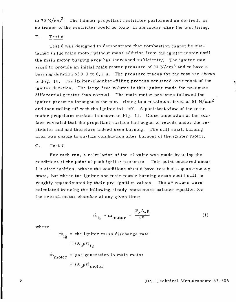
T e s t 6 was designed to demonst ra te that combustion cannot be sus -
tained in the ma in moto r without m a s s addition f r o m the igni ter mo to r until
t he ma in motor burning a r e a has inc reased sufficiently.
s ized to provide an init ial ma in ,moto r p r e s s u r e of 20 N/cm2 and to have a
burning duration of 0 . 3 to 0 . 4 s.
The ign i te r was
The p r e s s u r e t r a c e s for the t e s t a r e shown
in Fig. 10. The igni ter-chamber-f i l l ing p r o c e s s occur red over m o s t of the 7 igni ter duration.
different ia l g rea t e r than normal .
igni ter p r e s s u r e throughout the t e s t , r i s ing to a max imum level of 51 N/cm2
and then tailing off with the igni ter tail-off.
mo to r propellant surface i s shown in Fig. 11. Close inspection of the s u r -
face revealed that the propellant surface had begun to recede under the r e -
s t r i c t e r and had therefore indeed been burning.
a r e a was unable to sustain combustion a f t e r burnout of the. igni ter mo to r .
G. T e s t 7
The la rge f r e e volume i n th i s igni ter made the p r e s s u r e
The ma in moto r p r e s s u r e followed the
A pos t - tes t view of the ma in
The s t i l l s m a l l burning
F o r each run, a calculation of the C*C value was made by using the
conditions at the point of peak ign i te r p r e s s u r e . This point occu r red about
1 s after ignition, where the conditions should have reached a quas i - s teady
s ta te , but where the ign i te r and ma in m o t o r burning a r e a s could still be
roughly approximated by the i r pre-ignition values. The c*: va lues were
calculated by using the following s teady- s ta te m a s s balance equation for
the ove ra l l motor chamber at any given t ime:
where
m. = 18
- m - motor
- - PcAtg C* m. t m 1g moto r
the igni ter m a s s d i scha rge r a t e
(*bPr)ig
gas generat ion in m a i n m o t o r
(AbP "motor
JPL Technical Memorandum 33-506

Ab = unres t r i c t ed propellant burning a r e a
p = propellant density
r = propellant r eg res s ion ra te
P = the ma in motor chamber p r e s s u r e
At = the m a i n moto r nozzle throat a r e a
c* = the ma in motor charac te r i s t ic velocity
C
g = gravitational constant
The calculated c* values var ied between 760 and 900 m/s. Since the
values w e r e found to v a r y up to 60 m / s with small changes in the ma in m o t o r
p r e s s u r e chosen, the r e s u l t s a r e usable only f o r rough comparison.
theore t ica l low chamber -p res su re (70 N/cm2) c* value for both the igni ter
and m a i n motor propel lants i s approximately 1500 m/s, which i s 40-5070
higher than the values calculated f r o m the t e s t r e su l t s .
th is d i screpancy was probably due to heat l o s s e s to the heavy s t ee l aft-
c losu re of the motor . Since the final goal of this work i s to provide design
data for l a r g e r , flight-weight m o t o r s , a t e s t was pe r fo rmed to ver i fy this .
The
It was thought that
The in te r ior su r f ace of the motor a f t -c losure was insulated with
approximately a 0 . 6 cm-thick layer of V-61 ma te r i a l .
a r e a for th i s t e s t was r a i s e d s l igh t ly f rom that of T e s t 5.
c losure had an appreciable effect on the t e s t r e su l t s .
in i t ia l m a i n motor and igni ter p r e s s u r e s was 5070 higher than the va lues fo r
the previous th ree t e s t s . Through the u s e of Eq. ( l ) , a c* value of
1460 m/s was calculated f r o m the tes t data.
theore t ica l propel lant c* values should be able to be used in pre l iminary-
type calculations to s i ze ign i te rs for insulated, f l ight-type, solid-propellant
rocke t mot0 r s .
The igni ter burning
The insulated
The r a t io of the
This r e s u l t indicates that
H. T e s t 8
In a t tempts to apply labora tory motor L'k-P
de sign of l a r g e r extinguishable solid-propellant rocke t s , a motor - size
scaling effect was found to exist (Ref. 4). The l a r g e r m o t o r s extinguished
at lower p r e s s u r e s than would be predicted f r o m the labora tory data; i. e . ,
w e r e m o r e difficult to extinguish.
extinction data in the C
Although both the 12 . 7 cm-d iame te r
JPL Technical Memorandum 33-506 9

m o t o r used i n these t e s t s and the 7. 6 c m - d i a m e t e r moto r used to obtain
the L::-extinction c h a r a c t e r i s t i c s of the t e s t propel lant (F ig . 3 ) a r e sma l l
m o t o r s , a tes t was pe r fo rmed to obtain a n extinction data point under
moto r conditions similar to those used in this p r o g r a m .
A regress ive end-burner propel lant cha rge was machined and potted
in a 12. 7 cm-d iame te r moto r c h a m b e r , a s shown i n F ig . 12. The moto r
was f i r ed into the vacuum tank, a s i n the previous t e s t s .
pas te technique was used to ignite the 12. 7 c m - d i a m e t e r propel lant su r f ace .
The pyrotechnic
The motor p r e s s u r e reached a m a x i m u m of 90 N/cm2 and continued
to burn r eg res s ive ly unt i l extinction occur red at a m e a n chamber p r e s s u r e 2 of 28 N/cm , Typical L"-instability p r e s s u r e osci l la t ions f o r th i s type of
t e s t ( low frequency, low amplitude) began r a t h e r abrupt ly at a moto r p r e s -
s u r e of 70 N/crn2 and continued unt i l extinction.
p r e s s u r e oscil lations p r i o r to extinction was 8 Hz.
f r e e volume w a s m e a s u r e d at 1 X 10
of 11 m.
a m e a n extinction p r e s s u r e of 31 N/cm2.
sca t t e r i n this type of data.
The frequency of the
The pos t - tes t mo to r
m3, resu l t ing i n an extinction L"' - 3
At this L'" value the 7. 6 - c m motor data of Fig. 3 would predic t
This difference i s within the
JPL Technical Memorandum 3 3 - 506

V. TEST SERIES 2
F r o m Eq. ( 1 ) , the ini t ia l ma in motor p r e s s u r e i s a function of the
un res t r i c t ed propellant burning a r e a , the motor nozzle th roa t a r e a , and
the igni ter m a s s discharge r a t e . In any moto r design the nozzle throa t
a r e a would be fixed by the fully developed max imum chamber p r e s s u r e
des i red .
m a s s d ischarge r a t e were not systematical ly studied in the f i r s t t e s t s e r i e s ,
the un res t r i c t ed burning a r e a s reported in Table 1 having been a r b i t r a r i l y
chosen. In the effor t to minimize the requi red m a s s d ischarge r a t e , the
m a s s balance c r i t e r ion of F i g . 2 i s inadequate, a s it i s a n e c e s s a r y , but
not sufficient, condition fo r stable burning for moto r s in the low-pres su re ,
~OW-L::' region.
The effects of t rade-offs in unres t r ic ted burning a r e a and igniter
It was shown experimental ly ( R e f . 1 ) that a reduction in the second-
a r y fluid injection r a t e resu l ted in an inc reased minimum p r e s s u r e limit
f o r stable combustion, i. e . , combustion instabil i ty and extinction o c c u r r e d
at higher moto r chamber p r e s s u r e s .
out to de te rmine the effect of var ia t ion of the igni ter mo to r to ma in moto r
propel lant m a s s addition r a t e s ( the m. and m t e r m s of Eq. 1) on the
m a i n m o t o r L:: instabil i ty and extinction limits.
i s analogous to the fluid-to-solid ratio of Ref. 1.
A s e r i e s of moto r f i r ings was c a r r i e d
'g motor Their ra t io , mig/mmotor,
The t e s t sys t em was identical to that used fo r the f i r s t s e r i e s of
t e s t s , with the exception that , instead of being c a s t d i rec t ly , the main
m o t o r propel lant g ra ins were f i r s t machined to the des i r ed configuration
and then potted in the moto r chamber with Ecco Bond No. 4 5 cemen t ( E m e r s o n
& Cuming, Inc . ) .
e the r polyurethane binder , 16%-aluminized formulat ion with a t r imoda l
ammonium perchlora te oxidizer blended for reduced burning r a t e - p r e s -
s u r e c h a r a c t e r i s t i c s ( JPL 540 J) . Both propel lants have s i m i l a r low-
p r e s s u r e L" extinction cha rac t e r i s t i c s ( F i g . 3) and, though not investigated
in de ta i l , in the 7. 6 cm-ID m o t o r s their stabil i ty boundaries appeared to
be near o r g r e a t e r than 70 N/cmZ a t the L::' conditions tes ted. To allow
lower L': va lues , the moto r f r e e volume was reduced by par t ia l ly filling
the motor a f t -c losure with V-61 mater ia l .
propel lant of s e r i e s 1 was used a s the ign i te r propellant.
The propel lants used were Saturethane and l a t e r a poly-
The 2% aluminized polyurethane
JPL Technical Memorandum 33-506 11

The tes t r e su l t s a r e shown in Table 3. Initially the t e s t s y s t e m
consis ted of a r eg res s ive burning, ma in moto r propellant g ra in (Fig. 8) and a neutral igni ter mo to r .
ma in moto r p r e s s u r e would d e c r e a s e unt i l L" instabil i ty and eventually
extinction occurred . Instead, in two of the th ree t e s t s the mig/mmotor
ra t io increased sufficiently with decreas ing mmotor to enable the moto r s
to continue burning s tably until propellant burn-out.
It was expected tha t , following ignition, the
The tes t sys t em w a s then changed to a neut ra l ma in motor cha rge
and a r eg res s ive igni ter cha rge , resul t ing in a r eg res s ive ma in moto r
p re s su re - t ime his tory. F o r these t e s t s the ini t ia l p r e s s u r e s following
ignition i n the ma in moto r were held relat ively constant i n the low-pres su re
region (20-30 N/cm2) des i r ed for l a t e r sca led-up moto r t e s t s . By mini -
mizing the tes t f i r ing t i m e s and, consequently, the amount of ma in moto r
propellant consumed, be t te r cont ro l of the m a i n moto r f inal L': was a l s o
allowed.
and 3. 8 m.
could be properly ignited a t the low p r e s s u r e s a t tempted (20- 25 N/cmZ),
even with mig/mmotor va lues a s high a s 5. 7.
in a periodic manner until the igni ter propel lant was consumed.
Tests were per formed at ini t ia l L" values of approximately 2. 5
At an L" of 2. 5 m, nei ther of the ma in moto r propel lants
The m o t o r s would only chuff
At an init ial L* of approximately 3. 8 m (using JPL 540 J propellant
throughout) the m o t o r s were ignited a t ini t ia l p r e s s u r e s in the 20-30 N/cmZ
range.
f requencies of approximately 20 Hz) following ignition for approximately 1 s ,
extinguished, and then chuffed until the igni ter propellant was consumed. A
typical t e s t p re s su re - t ime t r a c e i s shown in Fig. 13. With f inal L$'s of
approximately 4 . 0 m, the m e a n chamber p r e s s u r e at extinction was found
to be inversely proport ional to the m e /mmotor ra t io , but r a t h e r weakly so 'g (F ig . 14). Of pe rhaps g r e a t e r consequence, the ampli tudes of the p r e s s u r e
osci l la t ions we r e found to d e c r e a s e with increas ing mig/mmotor ra t io , a s
shown in Table 3. It became apparent that in scaled-up m o t o r s with these
relat ively low L* va lues , the ign i te r mass flow r a t e s that would be requi red
to completely el iminate instabi l i ty in the 20-30 N/cm2 region would requi re
unacceptably la rge ign i te rs .
mi g l m m o to r ra t ios . so small that it was f e a r e d th i s might have some unforeseen effect .
In each t e s t the m a i n moto r burned unstably ( p r e s s u r e osci l la t ion
The t e s t s w e r e therefore not pursued to higher
The in i t ia l ma in m o t o r Kn va lues would a l s o become
JPL Technical Memorandum 33-506

VI. MASS BALANCE PROGRAM
In the design of a n ignit ion sys tem of th i s type f o r a m o t o r , a n
igni ter mo to r m a s s flow v s time profile and m a i n m o t o r propel lant r e -
s t r i c t e r configuration m u s t be chosen that w i l l give the d e s i r e d m a i n m o t o r
p r e s s u r e - t i m e profile.
mass balance of Eq. ( 1 ) was p rogrammed f o r solution on the IBM 1620
computer .
v s d i s tance burned i s first obtained f o r the d e s i r e d restricter configuration,
Imputing a n igni ter mo to r m v s t ime prof i le , the m a s s balance i s then
solved i te ra t ive ly at fixed dis tance-burned in te rva ls .
dis tance burned) the calculat ion a s s u m e s that the ign i te r and moto r a r e
completely ignited and at the i r ini t ia l equi l ibr ium p r e s s u r e conditions.
example of a typical m a i n moto r p r e s s u r e - t i m e calculat ion i s shown i n
F i g . 15.
f o r helping de termine the igni ter motor output/main m o t o r propel lant r e -
s t r i c t e r configuration combination requi red to give the approximate m a i n
moto r p r e s su re - t ime profile de s i red .
To a s s i s t i n this t a s k , the quas i - s teady-s ta te
An express ion fo r the main m o t o r ' s u n r e s t r i c t e d burning a r e a
At t ime z e r o ( z e r o
An
The p r o g r a m has been useful as a t r i a l - a n d - e r r o r design too l
I
1 3

VII. SUMMARY AND CONCLUSIONS
The feasibil i ty of the g-dot concept of controll ing p r e s s u r e build-up
in a solid-propellant mo to r was demonst ra ted , i n that sma l l solid-propellant
m o t o r s were ignited a t p r e s s u r e s significantly below the i r l ow-pres su re L-' extinction l imit and brought up to design operating p r e s s u r e in a control led
manner .
.D,
The ratio of the ma in moto r and igni ter nozzle throa t a r e a s was found
to be an important design p a r a m e t e r .
c a s e in T e s t 1 , an excessively l a rge propel lant burning a r e a i s requi red in
the igni ter to adequately p r e s s u r i z e the ma in moto r .
a s i n T e s t s 2 and 3 , it i s difficult to design an igni ter motor with a high
enough chamber p r e s s u r e - t i m e h is tory t o ensu re sonic nozzle flow through-
out i t s burning t ime.
If the r a t io i s too l a r g e , a s was the
If the ra t io i s too low,
The important p a r a m e t e r s in controll ing the ra te of p r e s s u r e i n c r e a s e
of the moto r a r e the moto r ini t ia l p r e s s u r e , the r eg res s ive burning c h a r a c t e r -
i s t i c s of the igniter motor and, of c o u r s e , the propellant r e s t r i c t e r configura-
tion.
r e g r e s s under the r e s t r i c t e r and r each the s teady-state burning a r e a . The
ini t ia l p r e s s u r e of Tes t 7 was approximately five t i m e s that of T e s t 4 , and
the moto r reached i ts max imum p r e s s u r e value in one-half the t ime .
The higher the init ial p r e s s u r e , the m o r e rapidly the propellant will
In Tests 4 and 5 , the ma in motor c l ea r ly exhibited a f a i r ly m a r k e d
in te rva l of low-frequency p r e s s u r e osci l la t ions below a chamber p r e s s u r e
leve l of roughly 30 N/cm2.
tude to exceed the des i r ed p r o g r a m g-dot cons t ra in ts .
in te rva l occur red below the L" extinction p r e s s u r e fo r the m o t o r ( T e s t 8
r e sul ts) .
The osci l la t ions w e r e of sufficiently high ampl i -
The osci l la t ion
Fur the r t e s t s showed this instabil i ty to be sensi t ive to the moto r
cha rac t e r i s t i c length L': and the ign i te r mo to r to m a i n m o t o r propel lant
m a s s addition r a t e s ra t io m. /mmotor. Increasing the m. /mmotor ra t io
dep res sed t h e mo to r L':: extinction p r e s s u r e and reduced the ampli tudes of
the p r e s s u r e osci l la t ions, but the instabi l i ty pe r s i s t ed at the L':' and moto r p r e s su re conditions investigated up to the highest mig/mmotor ra t io s
tes ted. A s predicted f r o m p r e s e n t L" instabi l i ty theo r i e s , Ref. 5 a s a n
example, lowering the moto r L':' i nc reased the exponential growth ra te
18 18
JPL Technical Memorandum 33-506
constant for the amplitude of oscil lations, producing s t ronge r p r e s s u r e
oscil lations and chuffing.
p r e s s u r e instabil i ty region should be kept to a minimum, cutting down on
the t ime for growth of the osci l la t ion amplitudes.
It was concluded that the burning t ime in the low-
i I
JPL Technical Memorandum 33-506
In the f i r s t t e s t s e r i e s , i r r e g u l a r , nonperiodic p r e s s u r e per turbat ions
occur red in the ma in motor .
low-frequency instabil i ty and often continued to occur throughout the burn-
ing t i m e of the motor .
a good dea l of a luminum and alumina deposition on the nozzle inlet and throat
regions.
such a build-up and sluffing off of solid m a t e r i a l in the throa t region can
produce per turbat ions in the measu red moto r p r e s s u r e . At p r e s e n t it i s
postulated that the i r r e g u l a r p r e s s u r e oscil lations experienced in this work
have the s a m e origin.
this que stion.
They appeared to be superimposed upon the
Pos t - f i re examination of the m o t o r s a lways revealed
It has been concluded f r o m previous sma l l mo to r experience that
Fu tu re scaled-up motor f i r ings should help to c la r i fy
A quasi-s teady-state m a s s balance express ion , with an a s s u m e d motor
c:: efficiency of 9070, was extensively used a s a tool fo r predicting the ini t ia l
equi l ibr ium p r e s s u r e conditions in the insulated ma in moto r and, to a l e s s e r
extent, fo r predicting the approximate ma in motor p r e s s u r e - t i m e history.
This pe r fo rmance p a r a m e t e r i s being used f o r p re l imina ry g-dot ignition
sys t em de sign.
1 5

REFERENCES
1. Coates , R . L. , Study of Fluid-Controlled Solid Propel lant Rocket Motors (Re s ta r tab le Solid, Variable Pulse (RSVP) Motor) ( Title Unclassified), F ina l Report R-LPC-734-F. Lockheed Ai rc ra f t Corp. , Propuls ion Division, Redlands, Calif . , Aug. 1967 (Confidential).
2. Strand, L. D . , Summary of a Study of the Low-Pressu re Combustion of Solid Propel lan ts , Technical Repor t 32-1242, pp. 22-23. J e t P r o - pulsion Labora tory , Pasadena , Ca l i f . , Apr . 15, 1968.
3. P e r r y , E . H . , "T-Burner Studies ," in Supporting Resea rch and Advanced Development, Space P r o g r a m s Summary 37-54, Vol. 111, pp. 93-96. Jet Propuls ion Labora tory , Pasadena , Calif. , Dec. 1968.
4. Levinsky, C. T . , and Kobal ter , G. F. , Feasibi l i ty Demonstrat ion of a Single-Chamber Controllable Solid Rocket Motor , Quar te r ly P r o g r e s s Report No. 4 , R P L TR-66-164. Aero je t -Genera l Corporat ion, Sacramento, Calif. , June 1966 (Confidential).
5. Beckstead, M. W . , and P r i c e , E. W . , "Nonacoustic Combustor Instabil i ty," ALAA J. , Vol. 5 , No. 11, pp. 1989-1996, 1967.
JPL Technical Memorandum 33-506
I
c 0 .d c,
2 k 0 w c .d
c, rn a, c,
k 0 c, 0
c E .d
2 5 c Id k a,
c M
c, .d
H
.. 4
rn a, .d k a, ul c, m a, E-l
4
a, .o Id
4
I3
k 0 c, : k a, c, .d e M
Id
H h
u
u
c, c
k 0 4 Id .d c, .d c H
c, rn a, F
0 0 0 0 0 0 0
\o m
d 0 t- d cc) m
d
* -+ In \o 0 4
0 0
0 Crl d
0
m * co m 0 \o 4 F 4 d 0 d
0 0 0 0
k a, a c x u .d 4
I a, c id 9 ;2 c, Ids v 1 0
I I I I a, c Id
a, k
5
4 g2 0s PlN
a, d
k
g z 4 o s PlN
u c c U
.d
0- z u c d u a,
.d
E' a, c, rn x rn a, c, m Id a u c d V a, c, 0 k k- a x .o k-
.d
4 c, 0 a, k
4 a a, c, .d e M
k 0 c,
.d
i3 2 c .d
JPL Technical Memorandum 33-506 1 7
18
idN
: E 4 "
c 3
id k
.3 +l
$3 rr: .y 25 " E J)"
r r id .3 :: E E " 3
. v N C - a ,
c r id
r C E ? . " 3
. * N C - u
.3
7 :
r - 9
E
7 : E E r-n
-3
" 2
.* N C .-a,
I I
id a, &- id
id
L
*
5 a, < N 0
3
id GI L id
w. C
0".
4
+'
.3 c
- 2 U c
id
li a 3 &- c 0
0
id N
4 4
- .r( *
id L'
JPL Technical Memorandum 33-506

Table 2. Tes t S e r i e s 1: Numer ica l t e s t r e s u l t s
1
2
3
4
5
6
7
1111 L l d l
141
160
150
3 50
460
4 50
e r ’ N/cm2
v i ax i r I iu~ LI
170
160
190
20 0
410
70 0
50 0
ime between pres sure .
Pmotor N / c m 2
iniii a 1
38
1 5
6. 2
13
21
30
Maximum
1 . 4
96
110
120
83
51
160
a ti’ s
2 7 runc a t e d
10
11 1/2
8 112
0.4
5 1/2
Init ial dP/dt,
~ / c m2/ s
41
4 5
5. 4
1 5
66
Overa l l maximum
dP/dt, N/cmZ/s
17
17
19
9 . 0
145
29
ignition and attainment of maximum m a i n moto r
JPL Technica l Memorandum 33-506 19
rn c, d
m a, k
a c Id e 0
5
.d c,
E" k 0 w c .d
c, rn a, b .. N
0 a, .d k Q) 10 c, rn
rr)
a, a 4
2
c 0
e M
k 0 CI 0
c
.d c, .rl
.rl
E .d
E" M c
0
0
e 0
.rl
3 l-l 4
w cn
*d c,
% e 0 u Id
c
4
.d c, .d
H
I L
.)
k
a
k N
o u S E
pc
k
s c o?c z
c 5 tz
Id
m F m o m m m N c O m * O N + d O d d O N 0 0 0 0 0 0 0 0 0 0
0 0 0 0 0 0 0 0 0 0
20 JPL Technica l Memorandum 33-506
(0
c 0
id .r( c,
4 A .r(
v ul 0
m & 3 ul 0
a”
(0
c, c
2 E 0 u
m
c 3 e:
0 \D P- 3 3 r“
id
0 0 0 0 !7
Ln Ln m m N W 0
L n L n W m m 3 0 N 0 0 0 0
0 0 0 0
0 P- 0. 3 0 3
0 0 0
0 0 0
id o m c, 3 3 (d 0 0 a 0
2 0 2 0 0
Ln a W N N 3 0 0 0
0 0 0
\D
+ w m M r C I m N 3 m W
N d N
(d
a +I
(d N m W m 0 N
N N W * * 3 3 3
Q P - m W 2 W -+ m \D P- W m o 3 r\:
3 3 3 3 3 H 3 3 3
JPL Technical Memorandum 33-506 21

A -A
240 t \ 1
W M a
80 - - L * LIMIT
- 40 -
14 16 0 2 4 6 8 10 12 TIME, I
Fig . 1. Low-accelerat ion ignition concept
16%-ALUMINIZED SATURETHANE PROPELLANT NOZZLE THROAT DIAMETER = 1.02 cm
,m &
2 0.04 - IGNITER MASS DISCHARGE RATE
MAGNITUDE REQUI ED FOR 3 0.03 - MOTOR WITH 32 wn9 BURNING,
AREA TO OPERATE AT U THIS PRESSURE
Y
2 M
0 10 20 30 40 50 60 70 80
Pc, N/cm 2
Fig . 2. Motor propel lant gasification r a t e kg and nozzle exhaust flow r a t e me v s moto r chamber p r e s s u r e , with moto r propel lant burning a r e a Ab a s independent p a r a m e t e r
22 JPL Technical Memorandum 33-506
2
1
E
2
I I I SATURETHANE PROPELLANT
0 7.6-cm-DIAM MOTOR TESTS
0 TEST 8
12.7-cm END BURNER
JPL 540 J. PROPELLANT \
1
JPL Technical Memorandum 33-506
[7 7.6 -cm-DIAM MO TO R
20 40 60 80
Fig. 3. L* v s mean chamber p r e s s u r e a t com- bustion extinction
23

a
IGNll
PROP ELLA NT
INHIBITOR
SECTION A-A
LTEST MOTOR
F i g . 4. Test s y s t e m
Fig. 5. Ign i t e r end-burner p r o p e l l a n t c h a r g e , T e s t 4
JPL Technica l M e m o r a n d u m 33-506

Fig. 6. T e s t s y s t e m mounted on v a c u u m tank in l e t pipe
125 r I N
E
z <
z P
MAIN MOTOR IGNITER MOTOR 100- ----
75 -
- 200
- 150
100
50
------_ - \------
I I I I I I I I I I 0 0 1 2 3 4 5 6 7 8 9 1 0 1 1
TIME, s
(u
E
Z < W rY
cn ul W rY a
3
F i g . 7. Ign i te r motor and m a i n m o t o r t e s t p r e s s u r e - t ime t r a c e s , T e s t 3
JPL Techn ica l M e m o r a n d u m 33-506 2 5
r O . 3 2 crn
26
12.7
F i g . 8. Main motor propel lant r e s t r i c t e r config- urat ion, T e s t s 4-7
I I I I 1 I I I 1 I I I N
MAIN MOTOR E < IGNITER MOTOR Z
200 . -150 2
------- E
- w PI
/------
Ln -- w _---- - mz 100 E PI
-50 $! 0 - 0 2 PI w I- - Z (3 -
0 1 2 3 4 5 6 7 8 9 10 11 12 13
TIME, s
Fig. 9. Igni ter motor and main motor t e s t p r e s s u r e - t ime t r a c e s , Tes t 4
JPL Technical Memorandum 33-506

I I I I I I I 800 c-4 E
Z /-'\ MAINMOTOR -600 -- <
2
\ 0, - 200 *
--------- - 0 2
z / i -
IGNITER MOTOR / \
\ ----- / \
\ \ \
/ L n w
- w 400 2
0
/ I
I I
CT Lu + - z
I I L -
O 0.2 0.4 0.6 0.8 1.0 1.2 1.4 1.6
TIME, s
Fig. 10. Igni ter mo to r a n d m a i n motor t e s t p r e s s u r e - t i m e t r a c e s , T e s t 6
Fig. 11. P o s t - t e s t view of m a i n m o t o r propel lan t su r f ace , Te s t 6
JPL T e c h n i c a l M e m o r a n d u m 33-506

28
12.7 I cm-
d k 0 . 3 2 c m \ \ \
/-.- MOTOR PROPELLANT CHAMBER
Fig. 12. Cross - sec t ion of r eg res s ive end-burner propellant charge , T e s t s 8, 10, and 11
Fig. 13. Igniter and ma in motor p r e s s u r e - t i m e r e c o r d s , T e s t 16
JPL Technical Memorandum 33-506

30m hl
E
z 20 Y
X a U
1 0 .
L* = 4.2 m
4.0 rn
101 I I I 0 1 2 3
Fig. 14. Main moto r mean p r e s s u r e at combus- t ion extinction v s r a t io of igni ter mo to r to m a i n motor propellant mass addition r a t e s
80- N
E
Z 60- -Y Y EL
Ln 3
Z 40 - E Lz
OI y1 FULLY DEVELOPED BURNING AREA m
U
0 I I I I I 0 1 2 3 4 5 6 7 8 9 1 0 1 1 1 2
TIME, 5
Fig. 15. Sample calculation: m a i n moto r mass balance computer p rogram, m a i n m o t o r p r e s s u r e v s time
JPL Technica l Memorandum 33-506 NASA - JPL - Coml., L.A., Calif.
29