lo-pro catalog 08 - complete 2 - mack automation, … catalog 08 - complete.pdf1-1/4 inches to 6...
TRANSCRIPT


© 2008 MACK CORPORATION Ph: (928)-526-1120 Fax: (928)-526-0473 Web: www .mackcorp.com Email: [email protected]
INDEXLO-PROfile ® Pneumatic Actuators
HI-ENERGY® Hydraulic Actuators
More Product s from Mack Corporation
BORE SIZE
0.450” THRU 1.700”0.450” THRU 1.700”0.450” THRU 1.700”0.450” THRU 1.700”0.450” THRU 1.700”0.450” THRU 1.700”0.450” THRU 1.700”0.450” THRU 1.700”0.329” THRU 1.493”0.450” THRU 1.950”0.450” THRU 1.950”0.450” THRU 1.450”0.450” THRU 1.450”
SEE PAGE FOR MORE INFO.1.800” THRU 4.800”1.800” THRU 4.800”1.800” THRU 4.800”1.800” THRU 4.800”1.800” THRU 4.800”1.800” THRU 4.800”1.950” THRU 4.500”1.950” THRU 4.500”0.450” THRU 1.700”0.450” THRU 1.700”0.450” THRU 1.700”0.450” THRU 1.700”0.450” THRU 1.700”
SEE PAGE FOR MORE INFO.SEE PAGE FOR MORE INFO.SEE PAGE FOR MORE INFO.SEE PAGE FOR MORE INFO.
0.341” THRU 0.883”0.341” THRU 0.883”15mm THRU 40mm15mm THRU 40mm15mm THRU 40mm0.800” THRU 1.493”0.450” THRU 1.700”0.450” THRU 1.700”1.800” THRU 4.800”1.800” THRU 4.800”1.800” THRU 4.800”
SEE PAGE FOR MORE INFO.SEE PAGE FOR MORE INFO.
0.450” THRU 1.200”0.450” THRU 1.200”0.450” THRU 1.200”0.925” THRU 1.600”1.800” THRU 4.800”
N/A
M.O.P
300 PSI300 PSI300 PSI300 PSI300 PSI300 PSI300 PSI300 PSI300 PSI300 PSI300 PSI300 PSI300 PSI150 PSI150 PSI150 PSI150 PSI150 PSI150 PSI150 PSI150 PSI150 PSI300 PSI300 PSI300 PSI300 PSI300 PSI150 PSI150 PSI150 PSI150 PSI150 PSI150 PSI20 BAR20 BAR20 BAR300 PSI300 PSI300 PSI150 PSI150 PSI150 PSI150 PSI150 PSI150 PSI150 PSI150 PSI150 PSI150 PSI150 PSI
STROKE
0.100 THRU 1.0000.100 THRU 4.0000.100 THRU 4.0000.100 THRU 4.0000.100 THRU 4.0000.100 THRU 1.0000.100 THRU 4.0000.100 THRU 4.0000.100 THRU 4.0000.100 THRU 4.0000.100 THRU 4.0000.100 THRU 4.0000.100 THRU 1.000
0.050 OR 0.1000.100 THRU 1.0000.100 THRU 4.0000.100 THRU 4.0000.100 THRU 4.0000.100 THRU 4.0000.100 THRU 1.0000.100 THRU 4.0000.100 THRU 1.0000.100 THRU 1.0000.100 THRU 1.0000.100 THRU 4.0000.100 THRU 4.0000.100 THRU 4.000
0.5000.5000.5000.500
0.100 THRU 2.0000.100 THRU 2.000
5mm THRU 100mm5mm THRU 100mm5mm THRU 100mm0.100 THRU 2.0000.100 THRU 1.0000.100 THRU 1.0000.100 THRU 1.0000.100 THRU 2.0000.100 THRU 2.0000.100 THRU 1.0000.100 THRU 1.0000.100 THRU 2.0000.100 THRU 2.0000.100 THRU 2.000
SEE PAGE FOR MORE INFO.0.100 THRU 2.000
N/A
CONFIGURATION
Ordering InstructionsMINIATURE SPRING RETURNMINIATURE, DOUBLE ACTING, SINGLE ENDEDMINIATURE, DOUBLE ENDED, THRU THREADMINIATURE, DOUBLE ENDED, THRU HOLEMINIATURE, DOUBLE ENDED, LARGE HUBMINIATURE, SINGLE ENDED, SPRING EXTENDMINIATURE, DOUBLE ENDED, THRU THREAD, EITHER FACE MOUNTEDMINIATURE, DOUBLE ENDED, THREADED BODY MOUNTINGMINIATURE, BUTTON, SINGLE ENDED, EXTERNAL FORCE RETURNMINIATURE, RAMS, SINGLE ENDED, EXTERNAL FORCE RETURNMINIATURE, FLATS, SINGLE ENDED, DOUBLE ACTINGMINIATURE, SINGLE ENDED, PISTON BACKS T O USER’S STRUCTUREMINIATURE, SPRING RETURN, PISTON BACK’S T O USER’S STRUCTURESUB-MINIATURE, SINGLE ENDED, SPRING RETRACTINGSTANDARD, SINGLE ENDED, SPRING RETURNSTANDARD, SINGLE ENDED, DOUBLE ACTINGSTANDARD, DOUBLE ENDED, DOUBLE ACTING, THRU THREADSTANDARD, DOUBLE ENDED, DOUBLE ACTING, THRU HOLESTANDARD, DOUBLE ENDED, DOUBLE ACTING , LARGE HUBSTANDARD, SINGLE ENDED, SPRING EXTENDSTANDARD, SINGLE ENDED, PIST ON BACKS T O USER’S STRUCTURESTANDARD, SPRING RETURN, PISTON BACKS T O USER’S STRUCTUREMINIATURE, POCKET MOUNTED, END PORTED, SPRING RETURNMINIATURE, POCKET MOUNTED, END INLET, SPRING RETURNMINIATURE, POCKET MOUNTED, SINGLE ENDED, END INLETSMINIATURE, POCKET MOUNTED, DOUBLE ENDED, END INLETSMINIATURE, POCKET MNTD., DOUBLE ENDED, THRU HOLE, END INLETSMINIATURE, RAMS, SINGLE ENDED, MANUAL RESET PISTONSMINIATURE, RAMS, SINGLE ENDED, MANUAL RESET, SIDE INLETSMINIATURE, RAMS, SINGLE ENDED, SPRING RETRACT, END PORTEDMINIATURE, RAMS, SINGLE ENDED, SPRING RETRACT, SIDE INLETSMINIATURE, RECTANGULAR, SINGLE ENDED, SIDE PORT, SIDE MOUNTMINIATURE, RECTANGULAR, SINGLE ENDED, MANIFOLD INLETSMINIATURE, PURE METRIC, SINGLE ENDED, DOUBLE ACTINGMINIATURE, PURE METRIC, DOUBLE ENDED, DOUBLE ACTINGMINIATURE, PURE METRIC, DOUBLE ENDED, THRU HOLEMINIATURE, BUTTON, EXTERNAL FORCE OR VACUUM RETRACT MINIATURE, NON-ROTATING PISTON, SPRING RETURNMINIATURE, NON-ROTATING PISTON, SPRING RETURN, POCKET MOUNTSTANDARD, SPRING RETURN, SINGLE ENDED, POCKET MOUNTEDSTANDARD, SINGLE ENDED, DOUBLE ACTING, POCKET MOUNTEDSTANDARD, DOUBLE ENDED, DOUBLE ACTING, POCKET MOUNTEDTWO-STAGE, DOUBLE ACTING, SINGLE ENDEDTWO-STAGE, DOUBLE ACTING, SINGLE ENDEDMODULAR, SINGLE MODULE, SINGLE ENDED, DOUBLE ACTINGMODULAR, DOUBLE MODULE, SINGLE ENDED, DOUBLE ACTINGMODULAR, TRIPLE MODULE, SINGLE ENDED, DOUBLE ACTINGFINGER CLAMP, DOUBLE ENDED, 10.7 - 62.5 LBS. OF FORCELARGE HOLLOW HUB, DOUBLE ENDED, DOUBLE ACTINGMANIFOLDPART NUMBER SEARCH
FOR UPDAFOR UPDATEDTED
INFORMAINFORMATION, VISITTION, VISIT
OUR WEBSITE OUR WEBSITE AATT::
wwwwww .mackcorp.com.mackcorp.com
PAGE
iiiL1L2L3L4L5L6L7L8L9
L10L11L12L13L14L15L16L17L18L19L20L21L22L23L24L25L26L27L28L29L30L31L32L33L34L35L36L37L38L39L40L41L42L43L44L45L46L47L48L49
ACC-1
Hydraulic actuators ranging in size from 1-1/4 inches to 6 inches O.D. Maximum operating pressures up to 3000 PSI.Travels ranging from .100 inch to 4 inches.
Robotic components which may be integrated intoseveral dozen different configurations for simplebench-top pick and place applications which do notjustify the cost of sophisticated servo systems.
B•A•S•E® Robotic Component s
Modifications may be made to st andard product s upon request.

© 2008 MACK CORPORATIONPh: (928)-526-1120 Fax: (928)-526-0473 Web: www .mackcorp.com Email: [email protected]
Ordering Cylinders
BASICPARTNo.
1007100751008100851009100951010
Indicate length of piston travel.
Check SPECIFICATIONS
on the specific productpage to see
maximum piston travel.
Contact us for longer travels.
Select the BASIC PART NUMBER
on a product p age.
INSTRUCTIONS:
1 Indicate a travel in increment s of 1/10”.2 Add on options as either
prefixes or suffixes.3
See our index for the configurations on each page.
Then choose the size required based on
specifications from table.
Options vary with each product page.Check on the product page
to see what options are available and if they need to be added as a
prefix or suffix.
1008 10 ETW & FL+ +
= 1008-10-ETW-FLPart number 1008 with a 1” travel, external thread wrench flats and flange mounting.
S1008-10-ETW-FL
For same part with stainless steel pistons add prefix “S”.
SAMPLE:
Page: iii
For current pricing and availability , cont act us by phone, fax, email
or request a quot ation through our website.
SERVICE KITS:
For metric cylinders:Add the prefix “M” to the BASIC PART NUMBER. Indicate a travel in increments 2.5mm.
(See metric conversions at back of this catalog.)
Add on options in the same format.
Metric version of sample above without stainless steel pistons is:
M1008-25.0mm-ETW-FLwith stainless steel pistons is:
MS1008-25.0mm-ETW-FL
METRIC VERSIONS:To order service kits, simply as the suffix “-SK” to the basic part number. Travel does not need to be included in the service kitpart number.
Writtenas:
1/10”2/10”3/10”4/10”1/2”
6/10”...
1”...
2”
-1-2-3-4-5-6...
-10...
-20
Measures:
Example from page L1

© 2008 MACK CORPORATION Ph: (928)-526-1120 Fax: (928)-526-0473 Web: www .mackcorp.com Email: [email protected]
For easy ordering, see ORDERINGINSTRUCTIONS on page iii.
Data sheet 9131
Page: L1
SHORT STROKE PNEUMATIC CYLINDERS - LO-PROfile® SERIES A-SP-FMSingle Acting-Spring Retracting-Single Ended Pistons-Side Ported-Either Face Mounted
NOTES:Dimensions are nominal in U.S. CUST OMARY specifications.
METRIC CYLINDERS are dimensionally equivalent with clearance holes, counter -bores, threads & fasteners to metric specifications. See inside back cover for fas -tener conversion t able. There is no added cost for METRIC CYLINDERS.
An air/oil mist unit is recommended for internal lubrication. Where such unit s arenot practical, SER VICE KITS including seals & factory approved lube are available.
Cylinders may also be used in low pressure hydraulic and vacuum service.
Wrench flat s may not be necessary if cylinders can be pressurized in the retractedor extended position while tightening the rod joint.
Inquiries regarding modifications to BASIC CYLINDERS are always welcome.
BASICPARTNo.
1007-(-)*10075-(-)1008-(-)10085-(-)1009-(-)10095-(-)1010-(-)
1.0001.2501.5001.7502.0002.2502.500
0.6880.9381.1881.4381.6881.9382.188
0.2500.2500.3750.3750.6250.6250.625
4-404-40
10-3210-32
5/16-245/16-245/16-24
0.1880.1880.2810.2810.5000.5000.500
Table 1Table 10.4560.4560.9310.9310.931
0.5000.5000.8130.8131.1251.1251.125
0.3850.3850.4860.4860.6900.6900.690
0.1410.1410.1880.1880.2810.2810.281
0.3050.3050.4060.4060.6100.6100.610
0.0940.0940.1250.1250.1880.1880.188
0.0630.0630.1250.1250.1880.1880.188
0.1560.1560.1880.1880.2500.2500.250
0.4500.5750.7000.9501.2001.4501.700
0.1590.2600.3850.7091.1311.6512.270
O.D.A
BOLTCIRCLE
B
RODDIA.
CTHD.
F
WR.FLATS
G
BOSSLENGTH
E
BOSSDIA.
DLENGTH
H
OFF-SET
KDEPTH
JREAM
LWIDTH
MWIDTH
N
PISTONO.D.(IN.)
EXTENDPISTONAREA
(SQ. IN)
TABLE 1
PART NO. E
1007 -1 Thru -3 0.23110075 -1 Thru -3 0.2311007 -4 Thru -6 0.38110075 -4 Thru-6 0.3811007 -7 Thru-10 0.572 10075 -7 Thru-10 0.572
Mounting Holes4-40 Internal Threads4 Locations, On Front& Rear Faces.See Mounting Options.
+ Travel0.580
.432
Cover
Body
Spherical Rad.See Rod Options
.030
1/16 NPTF, See Port Options
TravelSee Note
SPECIFICATIONS:SERVICE: PLANT AIRM.O.P.: 300 PSITEMPERATURE: -40ºF to +250ºFPISTON TRAVEL: UP TO - 10 (1.00”)
MATERIALS:BODY & COVER: ALUMINUM ALLOYPISTON: ALUMINUM ALLOYSPRINGS: MUSIC WIRESEALS: VIT ON O RINGSFASTENERS: ALLOY STEEL
“F” Thd.1-1/2 Dia., Depth
1-1/2 Dia., Length
.200
.580+ Travel
.580
.580
.386
.386
.480
.144
.286
MountingStructure
MountingStructure
U.S.A. 10-32 Threaded Port s.Straight Thread.Flat Gasket Sealing.
Add suffix -1032.
Internal Thread W ith W rench Flat s
Add suffix -ITW .
No. 4-40 internally threaded holes at 4 locations in bothfront and rear faces.
This mounting style is supplied unlessotherwise specified.NOTE: On 1” O.D. & 1-1/4” O.D. models, remove coverretaining screws & use these threaded holes whenmounting to the cover side.
Thru clearance holes with C’bores in the body forNo. 4-40 I.S.H.C.S. at 4 locations.
Add suffix -CBB.NOTE: On 1” O.D. & 1-1/4” O.D. models, the coveris a loose p art and is ret ained with the mountingscrews.
This cover is larger with flange mounting to eitherside.Clearance holes are for No. 4-40 screws at fourlocations.
Add suffix -FL.
Mounting directly to user ’s structure providesthe lowest overall height. This mounting style issupplied with a face seal but without a coverplate.Surface finish of the mounting structure shouldbe 125 microinches or better .Internal threads are No. 4-40 at four locations.
Add suffix -T .
Alternate mounting to a user ’s structure toprovide a minimum overall height.This mounting style is supplied with a face sealbut without a coverplate.Surface finish of the mounting structure shouldbe 125 microinches or better .Clearance holes with C’bores are in the body forNo. 4-40 I.S.H.C.S. at four locations.
Add suffix -TC.
External Thread W ith W rench Flat s
Add suffix -ETW .
Slotted Rod End
Add suffix -SR.
Rod End W ith Lug
Add suffix -RL.
.200
“F” Thd., “G” W rench Flat s
“G” W rench Flat s
C
C
H
C
L
K
N
J
K
J
M
L
C
+Travel
+Travel
+Travel
+Travel
Cover
Face Seal
Face Seal
Spring force for BASIC CYLINDERS is sufficient to fully retractpistons. Higher spring force may be required for retractingloads att ached to rod ends. Please consult the factory .
CD
A
B
X
X
B
B
B
B A
A
+.500A
+.250A
A
A
A
Pictorial
SECT. X-X
45ºE
*Part number 1007 is not available as a Metric version
PORT OPTIONS:OPTIONAL ROD ENDS: OPTIONAL MOUNTING STYLES:
MATERIAL UPGRADES:
Stainless S teel Pistons
Add prefix S.
Stainless S teel Cylinders
Add prefix SS.

© 2008 MACK CORPORATIONPh: (928)-526-1120 Fax: (928)-526-0473 Web: www .mackcorp.com Email: [email protected]
For easy ordering, see ORDERINGINSTRUCTIONS on page iii.
Data sheet 9132
Page: L2
SHORT STROKE PNEUMATIC CYLINDERS - LO-PROfile® SERIES A-SP-FMDouble Acting-Single Ended Pistons-Side Ported-Either Face Mounted
NOTES:Dimensions are nominal in U.S. CUST OMARY specifications.
METRIC CYLINDERS are dimensionally equivalent with clearance holes,counterbores, threads & fasteners to metric specifications. See inside backcover for fastener conversion t able. There is no added cost for METRICCYLINDERS.
An air/oil mist unit is recommended for internal lubrication. Where suchunit s are not practical, SER VICE KITS including seals & factory approvedlube are available.
Cylinders may also be used in low pressure hydraulic and vacuum service.
Wrench flat s may not be necessary if cylinders can be pressurized in theretracted or extended position while tightening the rod joint.
Inquiries regarding modifications to BASIC CYLINDERS are always welcome.
BASICPARTNo.
1011-(-)10115-(-)1012-(-)10125-(-)1013-(-)10135-(-)1014-(-)
1.0001.2501.5001.7502.0002.2502.500
0.6880.9381.1881.4381.6881.9382.188
0.2500.3130.3750.5000.6250.6250.625
4-4010-3210-321/4-28
5/16-245/16-245/16-24
0.1880.2500.2810.3750.5000.5000.500
0.3050.3050.4060.6100.6100.6100.610
0.3850.3850.4860.6900.6900.6900.690
0.1410.1410.1880.2810.2810.2810.281
0.0940.0940.1250.1880.1880.1880.188
0.0630.0940.1250.1880.1880.1880.188
0.1560.1560.1880.2500.2500.2500.250
0.4500.5750.7000.9501.2001.4501.700
0.1590.2600.3850.7091.1311.6512.270
0.1100.1830.2750.5130.8241.3441.963
O.D.A
BOLTCIRCLE
B
RODDIA.
C
RODTHD.
D
WR.FLATS
EDEPTH
FLENGTH
G
OFF-SET
HREAM
JWIDTH
KWIDTH
L
PISTONO.D.(IN.)
EXTENDPISTONAREA
(SQ. IN)
RETRACTPISTONAREA
(SQ.IN.)
Mounting Holes4-40 Internal Threads4 Locations, On Front& Rear Faces.See Mounting Options.
+ Travel0.580
.432
Port 2
Port 2Port 1
Cover
Body
SECT. X - X
C
X
B
A
45º45º
X“D” Thread1-1/2 Dia., DepthSee Rod Options
.030
.250
Port s are 1/16 NPTF, See Port Options
TravelSee Note
SPECIFICATIONS:SERVICE: PLANT AIRM.O.P.: 300 PSITEMPERATURE: -40ºF to +250ºFPISTON TRAVEL: UP TO - 20 (2.00”)
MATERIALS:BODY & COVER: ALUMINUM ALLOYPISTON: ALUMINUM ALLOYSEALS: VIT ON O RINGSFASTENERS: ALLOY STEEL
“D” Thd., 1-1/2 Dia.,Depth
“D” Thd.,”E” W rench Flat s
C
C
C
G
F
J
F
K
H
B
B
B
B
A
A
A
A
A
A
A
C L
H
J
“E” W rench Flat s
1-1/2 Dia.,Length .200
.580+ Travel
.580
.580
.386
.386
.480
+.500
+.250
.144
.286
MountingStructure
MountingStructure
U.S.A. 10-32 Threaded Port s.Straight Thread.Flat Gasket Sealing.Add suffix -1032.
Port s may be IN-LINE for travelsfrom -5.Add suffix -IL.
Internal Threads W ith W rench Flat s
Add Suffix -ITW .
No. 4-40 internally threaded holes at 4 locations in bothfront and rear faces.This mounting style is supplied unless otherwise specified.NOTE: On 1” O.D. & 1-1/4” O.D. models, remove coverretaining screws & use these threaded holes whenmounting to the cover side.
Thru clearance holes with C’bores in the body forNo. 4-40 I.S.H.C.S. at 4 locations.
Add suffix -CBB.NOTE: On 1” O.D. & 1-1/4” O.D. models, the cover is aloose p art and is ret ained with the mounting screws.
This cover is larger with flange mounting to eitherside.Clearance holes are for No. 4-40 screws at fourlocations.
Add suffix -FL.
Mounting directly to user ’s structure providesthe lowest overall height. This mounting style issupplied with a face seal but without a coverplate.Surface finish of the mounting structure shouldbe 125 microinches or better .Internal threads are No. 4-40 at four locations.
Add suffix -T .
Alternate mounting to a user ’s structure toprovide a minimum overall height.This mounting style is supplied with a face sealbut without a coverplate.Surface finish of the mounting structure shouldbe 125 microinches or better .Clearance holes with C’bores are in the body forNo. 4-40 I.S.H.C.S. at four locations.
Add suffix -TC.
External Threads W ith W rench Flat s
Add Suffix -ETW .
Slotted Rod End
Add suffix -SR.
Rod End W ith Lug
Add suffix -RL.
.200
+Travel
+Travel
+Travel
+Travel
Cover
Face Seal
Face Seal
CoverBody
.432 .250
PICTORIAL
PORT OPTIONS: OPTIONAL ROD ENDS: OPTIONAL MOUNTING STYLES:
MATERIAL UPGRADES:
Stainless S teel Pistons
Add prefix S.
Stainless S teel Cylinders
Add prefix SS.

© 2008 MACK CORPORATION Ph: (928)-526-1120 Fax: (928)-526-0473 Web: www .mackcorp.com Email: [email protected]
For easy ordering, see ORDERINGINSTRUCTIONS on page iii.
Data sheet 9133
Page: L3
SHORT STROKE PNEUMATIC CYLINDERS - LO-PROfile® SERIES A-SP-FMDouble Acting-Double Ended Pistons W ith Thread For Thru Bolts-Side Ported-Either Face Mounted
NOTES:Dimensions are nominal in U.S. CUST OMARY specifications.
METRIC CYLINDERS are dimensionally equivalent with clearance holes, counterbores, threads& fasteners to metric specifications. See inside back cover for fastener conversion t able.There is no added cost for METRIC CYLINDERS.
An air/oil mist unit is recommended for internal lubrication. Where such unit s are not practical,SERVICE KITS including seals & factory approved lube are available.
Cylinders may also be used in low pressure hydraulic and vacuum service.
Wrench flat s may not be necessary if cylinders can be pressurized in the retracted or extendedposition while tightening the rod joint.
Inquiries regarding modifications to BASIC CYLINDERS are always welcome.
BASICPARTNo.
1015-(-)10155-(-)1016-(-)10165-(-)1017-(-)10175-(-)1018-(-)
1.0001.2501.5001.7502.0002.2502.500
0.6880.9381.1881.4381.6881.9382.188
0.2500.3130.3750.5000.6250.6250.625
4-4010-3210-321/4-28
5/16-245/16-245/16-24
0.1290.2060.2060.2810.3440.3440.344
0.1880.2500.2810.3750.5000.5000.500
0.3050.3050.4060.6100.6100.6100.610
0.3850.3850.4860.6900.6900.6900.690
0.0940.0940.1250.1880.1880.1880.188
0.1410.1410.1880.2810.2810.2810.281
0.0630.0940.1250.1880.1880.1880.188
0.1560.1560.1880.2500.2500.2500.250
0.4500.5750.7000.9501.2001.4501.700
0.1100.1830.2750.5130.8241.3441.963
O.D.A
BOLTCIRCLE
B
RODDIA.
C
RODTHD.
D
HOLEDIA.
E
WR.FLATS
FDEPTH
GLENGTH
HREAM
J
OFF-SET
KWIDTH
LWIDTH
M
PISTONO.D.(IN.)
NETPISTONAREA
(SQ. IN)
Mounting Holes4-40 Internal Threads4 Locations, On Front& Rear Faces.See Mounting Options.
+ Travel0.580
.432
Port 2
Port 2Port 1
A
B
E C
X
X
45º 45º
Cover+ Travel
Body
SECT. X-X
“D” ThreadThreaded for the entire length on -1 thru -10thread depth, 1-1/2 thd.dia. for -1 1 & longer .See Rod Options.
.030
.030
.250
Port s Are 1/16 NPTF, See Port Options
TravelSee Note
SPECIFICATIONS:SERVICE: PLANT AIRM.O.P.: 300 PSITEMPERATURE: -40ºF to +250ºFPISTON TRAVEL: UP TO - 20 (2.00”)
MATERIALS:BODY & COVER: ALUMINUM ALLOYPISTON: ALUMINUM ALLOYSEALS: VIT ON O RINGSFASTENERS: ALLOY STEEL
“D” Thd., 1-1/2 Dia., Depth
“D” Thd., “F” W rench Flat s
1-1/2 Dia., Length .200
C
C
C
K
J
M
H
JG
K
L
G
C
.580+ Travel
.580
.580
.480
B
B
A
A+.500
+.250
A
A
A
.144
U.S.A. 10-32 Threaded Port s.Straight Thread.Flat Gasket Sealing.
Add suffix -1032.
Port s may be IN-LINE for travelsfrom -5.
Add suffix -IL.
Internal Thread W ith W rench Flat s
Add suffix -ITW .
No. 4-40 internally threaded holes at 4 locations inboth front and rear faces.This mounting style is supplied unlessotherwise specified.NOTE: On 1” O.D. & 1-1/4” O.D. models, removecover ret aining screws & use these threaded holeswhen mounting to the cover side.
Thru clearance holes with C’bores in the body forNo. 4-40 I.S.H.C.S. at 4 locations.
Add suffix -CBB.NOTE: On 1” O.D. & 1-1/4” O.D. models, the coveris a loose p art and is ret ained with the mountingscrews.
This cover is larger with flange mounting to eitherside.Clearance holes are for No. 4-40 screws at fourlocations.
Add suffix -FL.
External Thread W ith W rench Flat s
Add suffix -ETW .
Slotted Rod End
Add suffix -SR.
Rod End W ith Lug
Add suffix -RL.
NOTES - Optional piston rod ends extend from the BODYSIDE and apply to one end only unless otherwise specified.However , pistons may be reversed. (End for end)
If required, add suffix -R.Piston rods have to internal machining on options -ETW , -SR and -RL.
.200 “F” W rench Flat s
+Travel
+Travel
Cover
CoverBody
.432 .250
Pictorial
PORT OPTIONS: OPTIONAL ROD ENDS: OPTIONAL MOUNTING STYLES:
MATERIAL UPGRADES:
Stainless S teel Pistons
Add prefix S.
Stainless S teel Cylinders
Add prefix SS.

© 2008 MACK CORPORATIONPh: (928)-526-1120 Fax: (928)-526-0473 Web: www .mackcorp.com Email: [email protected]
For easy ordering, see ORDERINGINSTRUCTIONS on page iii.
Data sheet 9134
Page: L4
SHORT STROKE PNEUMATIC CYLINDERS - LO-PROfile® SERIES A-SP-FMDouble Acting-Double Ended Pistons W ith Thru Holes-Side Ported-Either Face Mounted
NOTES:Dimensions are nominal in U.S. CUST OMARY specifications.
METRIC CYLINDERS are dimensionally equivalent with clearance holes, counterbores,threads & fasteners to metric specifications. See inside back cover for fastener con -version t able. There is no added cost for METRIC CYLINDERS.
An air/oil mist unit is recommended for internal lubrication. Where such unit s are notpractical, SER VICE KITS including seals & factory approved lube are available.
Cylinders may also be used in low pressure hydraulic and vacuum service.
Wrench flat s may not be necessary if cylinders can be pressurized in the retracted orextended position while tightening the rod joint.
Inquiries regarding modifications to BASIC CYLINDERS are always welcome.
BASICPARTNO.
1019-(-)10195-(-)1020-(-)10205-(-)1021-(-)10215-(-)1022-(-)
1.0001.2501.5001.7502.0002.2502.500
0.6880.9381.1881.4381.6881.9382.188
0.2500.3130.3750.5000.6250.6250.625
0.1290.2060.2060.2810.3440.3440.344
O.D.A
BOLTCIRCLE
B
RODDIA.
C
HOLEDIA.
D
Mounting Holes4-40 Internal Threads4 Locations, On Front& Rear Faces.See Mounting Options.
+ Travel0.580
.432
Port 2
Port 2Port 1
C
A
B
45º 45º
X
X
Cover
+ Travel
Body
SECT. X - X
“D” Dia.Thru HoleSee Rod Options
.030
.030
.250
Port s Are 1/16 NPTF, See Port Options
TravelSee Note
SPECIFICATIONS:SERVICE: PLANT AIRM.O.P.: 300 PSITEMPERATURE: -40ºF to +250ºFPISTON TRAVEL: UP TO - 20 (2.00”)
MATERIALS:BODY & COVER: ALUMINUM ALLOYPISTON: ALUMINUM ALLOYSEALS: VIT ON O RINGSFASTENERS: ALLOY STEEL
Cylinders with THRU HOLE pistons are normallysupplied without wrench flat s.Please consult the Factory if wrench flat s orother modification to the piston is required.
.580+ Travel
.580
.580
.480
+.500
+.250
B
BA
AA
A
A
.144
U.S.A. 10-32 Threaded Port s.Straight Thread.Flat Gasket Sealing.Add suffix -1032.
Port s may be IN-LINE for travelsfrom -5.Add suffix -IL.
No. 4-40 internally threaded holes at 4 locations in bothfront and rear faces.This mounting style is supplied unless oth -erwise specified.NOTE: On 1” O.D. & 1-1/4” O.D. models, remove coverretaining screws & use these threaded holes whenmounting to the cover side.
Thru clearance holes with C’bores in the body forNo. 4-40 I.S.H.C.S. at 4 locations.
Add suffix -CBB.NOTE: On 1” O.D. & 1-1/4” O.D. models, the cover is aloose p art and is ret ained with the mounting screws.
This cover is larger with flange mounting to eitherside.Clearance holes are for No. 4-40 screws at four loca -tions.
Add suffix -FL.
+Travel
+Travel
Cover
CoverBody
.432 .250
PISTONO.D.(IN.)
0.4500.5750.7000.9501.2001.4501.700
NETPISTONAREA
(SQ. IN)
0.1100.1830.2750.5130.8241.3441.963
PORT OPTIONS: ROD MODIFICATIONS: OPTIONAL MOUNTING STYLES:
MATERIAL UPGRADES:
Stainless S teel Pistons
Add prefix S.
Stainless S teel Cylinders
Add prefix SS.

© 2008 MACK CORPORATION Ph: (928)-526-1120 Fax: (928)-526-0473 Web: www .mackcorp.com Email: [email protected]
For easy ordering, see ORDERINGINSTRUCTIONS on page iii.
Data sheet 9135
Page: L5
SHORT STROKE PNEUMATIC CYLINDERS - LO-PROfile® SERIES A-SP-FMDouble Acting-Double Ended Pistons W ith Large Hubs-Side Ported-Either Face Mounted
NOTES:Dimensions are nominal in U.S. CUST OMARY specifications.
METRIC CYLINDERS are dimensionally equivalent with clearance holes, counterbores, threads & fas -teners to metric specifications. See inside back cover for fastener conversion t able. There is noadded cost for METRIC CYLINDERS.
An air/oil mist unit is recommended for internal lubrication. Where such unit s are not practical, SER -VICE KITS including seals & factory approved lube are available.
Cylinders may also be used in low pressure hydraulic and vacuum service.
Wrench flat s may not be necessary if cylinders can be pressurized in the retracted or extended posi -tion while tightening the rod joint.
Inquiries regarding modifications to BASIC CYLINDERS are always welcome.
BASICPARTNO.
1089-(-)10895-(-)1088-(-)10885-(-)1087-(-)10875-(-)1086-(-)
1.0001.2501.5001.7502.0002.2502.500
0.6880.9381.1881.4381.6881.9382.188
0.3750.4380.5300.6250.7000.7500.850
0.2500.2810.3750.5000.5630.6250.688
O.D.A
BOLTCIRCLE
B
RODDIA.
C
MAXHOLEDIA. D
Mounting Holes4-40 Internal Threads4 Locations, On Front& Rear Faces.See Mounting Options.
+ Travel0.580
.432
Port 2
Port 2Port 1
A
X
X
B
45º 45ºCover
C
+ Travel
SECT. X - X
BodySee Rod Options
.060
.060
.250
Port s Are 1/16 NPTF, See Port Options
TravelSee Note
SPECIFICATIONS:SERVICE: PLANT AIRM.O.P.: 300 PSITEMPERATURE: -40ºF to +250ºFPISTON TRAVEL: UP TO - 20 (2.00”)
MATERIALS:BODY & COVER: ALUMINUM ALLOYPISTON: ALUMINUM ALLOYSEALS: VIT ON O RINGSFASTENERS: ALLOY STEEL
Offered with large thru holes.Add suffix -TH to the BASIC PART NO.and st ate nominal hole diameter with tolerance.Add 5% to the BASE PRICE for any hole diameterwith tolerance to plus or minus .005 inch.If closer tolerance is required, please consult theFactory .
Normally supplied without wrench flat s, ifrequired, please consult the factory .
Please consult the Factory , if counterbores, special threads or other special treatment to the rod is required.
.580+ Travel
.580
.580
C
“D”
B
B
+.500A
+.250A
A
A
A
Max.
.480
.144
U.S.A. 10-32 Threaded Port s.Straight Thread.Flat Gasket Sealing.Add suffix -1032.
Port s may be IN-LINE for travelsfrom -5.Add suffix -IL.
No. 4-40 internally threaded holes at 4 locations inboth front and rear faces.This mounting style is supplied unlessotherwise specified.NOTE: On 1” O.D. & 1-1/4” O.D. models, removecover ret aining screws & use these threaded holeswhen mounting to the cover side.
Thru clearance holes with C’bores in the body forNo. 4-40 I.S.H.C.S. at 4 locations.
Add suffix -CBB.NOTE: On 1” O.D. & 1-1/4” O.D. models, the coveris a loose p art and is ret ained with the mountingscrews.
This cover is larger with flange mounting to eitherside.Clearance holes are for No. 4-40 screws at fourlocations.
Add suffix -FL.
+Travel
+Travel
Cover
CoverBody
.432 .250
PISTONO.D.(IN.)
0.4500.5750.7000.9501.2001.4501.700
NETPISTONAREA
(SQ. IN)
0.0490.1090.1640.4020.7461.2091.703
PORT OPTIONS: OPTIONAL PISTON MODIFICATION: OPTIONAL MOUNTING STYLES:
MATERIAL UPGRADES:
Stainless S teel Pistons
Add prefix S.
Stainless S teel Cylinders
Add prefix SS.

© 2008 MACK CORPORATIONPh: (928)-526-1120 Fax: (928)-526-0473 Web: www .mackcorp.com Email: [email protected]
For easy ordering, see ORDERINGINSTRUCTIONS on page iii.
Data sheet 9136
Page: L6
SHORT STROKE PNEUMATIC CYLINDERS - LO-PROfile® SERIES A-SP-FMSingle Acting-Spring Extending-Single Ended Pistons-Side Ported-Either Face Mounted
NOTES:Dimensions are nominal in U.S. CUST OMARY specifications.
METRIC CYLINDERS are dimensionally equivalent with clear -ance holes, counterbores, threads & fasteners to metric speci -fications. See inside back cover for fastener conversion t able.There is no added cost for METRIC CYLINDERS.
An air/oil mist unit is recommended for internal lubrication.Where such unit s are not practical, SER VICE KITS includingseals & factory approved lube are available.
Cylinders may also be used in low pressure hydraulic service.
Inquiries regarding modifications to BASIC CYLINDERS arealways welcome.
BASICPARTNo.
S1866-(-)S18665-(-)S1867-(-)S18675-(-)S1868-(-)S18685-(-)S1869-(-)
1.0001.2501.5001.7502.0002.2502.500
0.6880.9381.1881.4381.6881.9382.188
0.3750.4380.530.06250.7000.7500.850
4-4010-3210-321/4-28
5/16-245/16-245/16-24
0.2500.3130.3750.4380.5000.6250.625
0.2500.3130.3750.5000.5000.6250.625
0.4500.5750.7000.9501.2001.4501.700
0.0490.1100.1640.4020.7461.2091.703
O.D.A
BOLTCIRCLE
B
RODDIA.
C
RODTHD.
D
WR.FLATS
E
SPRINGPOCKET
F
PISTONO.D.(IN.)
NETPISTONAREA
(SQ. IN)
Mounting Holes4-40 Internal Threads4 Locations, On Front& Rear Faces.See Mounting Options.
+ Travel0.580
Cover
.250
Body
SECT. X - X
C
C
“D” Thread“E” W rench Flat s
“D” Thread“E” W rench Flat s
.125
CF
XA
B
45º
X“D” Thd.1 Thd. Dia., DepthSee Rod Options
1/16 NPTF PortSee Port Option
+Travel.060
SPECIFICATIONS:SERVICE: PLANT AIRM.O.P.: 300 PSITEMPERATURE: -40ºF to +250ºFPISTON TRAVEL: UP TO - 10 (1.00”)
MATERIALS:BODY & COVER: ALUMINUM ALLOYPISTON: STAINLESS STEELSPRINGS: MUSIC WIRESEALS: VIT ON O RINGSFASTENERS: ALLOY STEEL
1-1/2 Thd. Dia.
.580+ Travel
.580
.580
.386
.386
.480
B
B
B
B A
A
A
A
A
.144
+.500A
+.250A
.286
MountingStructure
MountingStructure
U.S.A. 10-32 Threaded Port s.Straight Thread.Flat Gasket Sealing.Add suffix -1032.
Internal Thread W ith W rench Flat s
Add suffix -ITW .
Thru clearance holes with C’bores in the body forNo. 4-40 I.S.H.C.S. at 4 locations.
Add suffix -CBB.NOTE: On 1” O.D. & 1-1/4” O.D. models, the coveris a loose p art and is ret ained with the mountingscrews.
No. 4-40 internally threaded holes at 4 locations inboth front and rear faces.This mounting style is supplied unlessotherwise specified.NOTE: On 1” O.D. & 1-1/4” O.D. models, removecover ret aining screws & use these threaded holeswhen mounting to the cover side.
This cover is larger with flange mounting to eitherside.Clearance holes are for No. 4-40 screws at fourlocations.
Add suffix -FL.
Mounting directly to user ’s structure providesthe lowest overall height. This mounting style issupplied with a face seal but without a coverplate.Surface finish of the mounting structure shouldbe 125 microinches or better .Internal threads are No. 4-40 at four locations.
Add suffix -T .
Alternate mounting to a user ’s structure toprovide a minimum overall height.This mounting style is supplied with a face sealbut without a coverplate.Surface finish of the mounting structure shouldbe 125 microinches or better .Clearance holes with C’bores are in the body forNo. 4-40 I.S.H.C.S. at four locations.
Add suffix -TC.
External Thread W ith W rench Flat s
Add suffix -ETW .
Spring force for BASIC CYLINDERS is sufficient to fully extendpistons. Higher spring force may be required in some cases. Pleaseconsult the Factory with your force requirement s.
.260 +Travel
.260 +Travel
+Travel
+Travel
+Travel
+Travel
Cover
Face Seal
Face Seal
A Spring Pocket will be necessary in the user ’s structure whenusing mounting option -T or -TC. See diameter & depth in themean view . The mounting bolt p attern should be concentric withthe spring pocket within a tot al indicator reading of .005 inch.
PORT OPTIONS:
OPTIONAL ROD ENDS:
OPTIONAL MOUNTING STYLES:
MATERIAL UPGRADES:
Stainless S teel CylindersAdd prefix S.

© 2008 MACK CORPORATION Ph: (928)-526-1120 Fax: (928)-526-0473 Web: www .mackcorp.com Email: [email protected]
For easy ordering, see ORDERINGINSTRUCTIONS on page iii.
Data sheet 9137
Page: L7
SHORT STROKE PNEUMATIC CYLINDERS - LO-PROfile® SERIES A1-SP-FMDouble Acting-Double Ended Pistons with Internal Threads-Side Ported-Either Face Mounted
NOTES:Dimensions are nominal in U.S. CUST OMARY specifications.
METRIC CYLINDERS are dimensionally equivalent withclearance holes, counterbores, threads & fasteners to met -ric specifications. See inside back cover for fastener con -version t able. There is no added cost for METRIC CYLIN-DERS.
An air/oil mist unit is recommended for internal lubrication.Where such unit s are not practical, SER VICE KITS includingseals & factory approved lube are available.
Cylinders may also be used in low pressure hydraulic andvacuum service.
Wrench flat s may not be necessary if cylinders can be pres -surized in the retracted or extended position while tighten -ing the rod joint.
Inquiries regarding modifications to BASIC CYLINDERS arealways welcome.
NOTE 2Not available on Model 1031-(-)
NOTE 1C= 0.832 + Travel (A=D)
BASICPARTNo.
1031-(-)*1032-(-)1033-(-)1034-(-)
1.0001.5002.0002.500
0.6880.7501.1881.688
See note10.5630.5630.563
1.0001.0001.5002.000
0.3750.5000.8751.375
0.2500.3750.6250.625
4-4010-32
5/16-245/16-24
0.1290.2060.3440.344
See Note 21.2501.7502.250
0.1880.2810.5000.500
0.4500.7001.2001.700
0.1100.2750.8241.963
O.D.A
BOLTCIRCLE
B
FLANGELENGTH
C
BOSSDIA.
D
BOTHRECESS
DIA.E
RODDIA.
FTHD.
GHOLE
H
BOLTCIRCLE
J
WR.FLATS
K
PISTONDIA.(IN.)
PISTONAREA
(SQ. IN)
Mounting Holes4-40 Internal Threads4 Locations, On Front& Rear Faces.See Mounting Options.
+ Travel0.832
.170
.125 DepthBoth Sides
COVER
“H” Dia.
TravelTravel.094
BODY
NOTE:Piston May Be Reversed (End for End)
“G” ThreadLength, 1-1/2 Dia.For -11 thru -20.Threaded for Entire Length.For -1 thru -10.See Rod Options.
.094
C
D
A
B
45º
X
X
FE
.160
Both Faces
NOTE: Port s Are No. 10-32
SPECIFICATIONS:SERVICE: PLANT AIRM.O.P.: 300 PSITEMPERATURE: -40ºF to +250ºFPISTON TRAVEL: UP TO - 20 (2.00”)
MATERIALS:BODY & COVER: ALUMINUM ALLOYPISTON: ALUMINUM ALLOYSEALS: VIT ON O RINGSFASTENERS: ALLOY STEEL
COVER
COVER
Thru Clearance Holes For 4-40 ScrewsAdd suffix -CL.*Not Available on 1031-(-)
Double Acting - Single Ended V ersionRod Extends From The Body SideAdd suffix -SEB.
Piston W ith Thru Hole.
Add suffix -TH.
Internal Thread W ith W rench Flat sExtending From The Body Side.
Add suffix -ITW .
Extrnal Thread W ith W rench Flat sExtending From The Body Side.
Add Suffix -ETW .
NOTES- Optional piston rod ends extend from the BODY SIDEand apply to one end only unless otherwise specified. However ,pistons may be reversed. (End for End)
If required, add suffix -R.Piston rods have no internal machining on option -ETW .
Double Acting - Single Ended V ersionRod Extends From The Cover SideAdd suffix -SEC.
BODY
BODY
1/8 (0.125) Holes4 Places22-1/2º From Port
J
.030
H
.030
.170
.1701-1/2Thd.Dia.
“G” Thd.1-1/2 Depth“K” W rench
Flats
“G” Thd.“K” W rench
Flats
OPTIONAL CONFIGURATIONS: OPTIONAL ROD ENDS:OPTIONAL MOUNTING STYLES:
MATERIAL UPGRADES:
Stainless S teel PistonsAdd prefix S.
Stainless S teel CylindersAdd prefix SS.

© 2008 MACK CORPORATIONPh: (928)-526-1120 Fax: (928)-526-0473 Web: www .mackcorp.com Email: [email protected]
For easy ordering, see ORDERINGINSTRUCTIONS on page iii.
Data sheet 9138
Page: L8
SHORT STROKE PNEUMATIC CYLINDERS - LO-PROfile® SERIES A2-SP-TMDouble Acting-Double Ended Pistons with Internal Threads-Side Ported-Thread Mounted
NOTES:Dimensions are nominal in U.S. CUST OMARY specifications.
METRIC CYLINDERS are dimensionally equivalent with clear -ance holes, counterbores, threads & fasteners to metric spec -ifications. See inside back cover for fastener conversiontable. There is no added cost for METRIC CYLINDERS.
An air/oil mist unit is recommended for internal lubrication.Where such unit s are not practical, SER VICE KITS includingseals & factory approved lube are available.
Cylinders may also be used in low pressure hydraulic andvacuum service.
Wrench flat s may not be necessary if cylinders can be pres -surized in the retracted or extended position while tighteningthe rod joint.
Inquiries regarding modifications to BASIC CYLINDERS arealways welcome.
NOTE 2Not available on Model 1044-(-)
NOTE 1C= 0.832 + Travel (A=D)
BASICPARTNo.
1044-(-)*1045-(-)1046-(-)1047-(-)
1.0001.5002.0002.500
0.6880.7501.1881.688
See note10.5630.5630.563
1.0001.0001.5002.000
0.3750.5000.8751.375
0.2500.3750.6250.625
4-4010-32
5/16-245/16-24
0.1290.2060.3440.344
See Note 21.2501.7502.250
1/2-203/4-161-141-14
0.4500.7001.2001.700
0.3130.5000.7500.750
0.5000.7501.0001.000
0.1100.2750.8241.963
0.7500.9381.2501.250
0.3750.4380.5000.500
O.D.A
BOLTCIRCLE
B
FLANGELENGTH
C
BOSSDIA.
D
RECESSDIA.
E
RODDIA.
FTHD.
GHOLE
H
BOLTCIRCLE
JTHD.
K
PISTONDIA.(IN.)
RECESSDIA.
L
NOM.O.D.
M
NETPISTONAREA
(SQ. IN)
SHOULDERDIA.N
LENGTHP
+ Travel0.832
Travel
.170
Cover
BE F
“H”
M
N
D
A
45º
X
X
P
.126 Deep
“P” + .120+0.094
Travel
SECT. X-X
4-40 Internal Thd.4 Locations
Body
L
“G” ThreadLength, 1-1/2 Dia.For -11 thru -20.Threaded for Entire Length.For -1 thru -10.See Rod Options.
“K” Thd.
.030
.030
.160
NOTES:Port s are st andard No. 10-32 Thd.Piston may be reversed (End for End)
SPECIFICATIONS:SERVICE: PLANT AIRM.O.P.: 300 PSITEMPERATURE: -40ºF to +250ºFPISTON TRAVEL: UP TO - 20 (2.00”)
MATERIALS:BODY & COVER: ALUMINUM ALLOYPISTON: ALUMINUM ALLOYSEALS: VIT ON O RINGSFASTENERS: ALLOY STEEL
MACHINING STANDARDS FOR BULKHEAD MOUNTING WITH “O” RING SEALING
COVER
COVERThru Clearance Holes For 4-40 ScrewsAdd suffix -CL.*Not Available on 1044-(-)
Double Acting - Single Ended V ersionRod Extends From The Body Side
Add suffix -SEB.
Double Acting - Single Ended V ersionRod Extends From The Cover Side
Add suffix -SEC.
BODY
BODY
CYLINDERS WITH BULKHEAD SEALS
Add suffix -OR.
Piston with a thru hole
Add suffix -TH.
1/8 (0.125) Holes4 Places22-1/2ºFrom Port
J
H
“O” Ring
AA
BB
.125
Drill CCThd. DD
FORPARTNo.
1044-(-)1045-(-)1046-(-)1047-(-)
0.5980.8411.0691.069
0.3750.4380.5000.500
0.4530.6880.9380.938
1/2-203/4-161-141-14
2-1112-1142-1182-118
SEALRECESS
AA
MIN.WALL
BB
TAPDRILL
CCTHD.DD
“O” RINGSIZE
OPTIONAL PISTON:
OPTIONAL CONFIGURATIONS:OPTIONAL MOUNTING STYLES:
MATERIAL UPGRADES:
Stainless S teel PistonsAdd prefix S.
Stainless S teel CylindersAdd prefix SS.

© 2008 MACK CORPORATION Ph: (928)-526-1120 Fax: (928)-526-0473 Web: www .mackcorp.com Email: [email protected]
For easy ordering, see ORDERINGINSTRUCTIONS on page iii.
Data sheet 9139
Page: L9
SHORT STROKE PNEUMATIC CYLINDERS - LO-PROfile® SERIES A-EP-FM-BUTTONSSingle Acting-Extenal Force Return-Single Ended Pistons-End Ported-Face Mounted
NOTES:Dimensions are nominal in U.S. CUST OMARY specifications.
METRIC CYLINDERS are dimensionally equivalent with clear -ance holes, counterbores, threads & fasteners to metric speci -fications. See inside back cover for fastener conversion t able.There is no added cost for METRIC CYLINDERS.
An air/oil mist unit is recommended for internal lubrication.Where such unit s are not practical, SER VICE KITS includingseals & factory approved lube are available.
Cylinders may also be used in low pressure hydraulic service.
Inquiries regarding modifications to BASIC CYLINDERS arealways welcome.
BASICPARTNo.
S2300-(-)S2301-(-)S2302-(-)S2303-(-)S2304-(-)S2305-(-)
1.0001.2501.5001.7502.0002.250
0.7501.0001.2501.5001.7502.000
0.1880.3750.6250.8751.0001.000
1.0001.3752.0002.6253.5004.250
4-4010-32
5/16-245/16-245/16-245/16-24
0.1560.2810.5000.5000.5000.500
0.3290.5500.8001.0551.2431.493
0.0850.2380.5030.8741.2131.750
O.D.A
BOLTCIRCLE
B
RAMDIA.
C
SPHERICALRADIUS
DTHD.
E
WRENCHFLATS
F
PISTONDIA.(IN.)
PISTONAREA
(SQ. IN)
Drilled and C’bored for4-40 I.S.H.C.S4 LocationsSee Internal Thread Option.
+ Travel0.200
+ Travel.350
Travel
User ’s MountingStructureSee Cover Option
.156
“D” S pherical RadiusFor The Entire UpperSurface.
Face Seal Is Supplied
A
B
C
ExternalReturnForce
SPECIFICATIONS:SERVICE: PLANT AIRM.O.P.: 300 PSITEMPERATURE: -40ºF to +250ºFPISTON TRAVEL: UP TO - 20 (2.00”)
MATERIALS:BODY & COVER: ALUMINUM ALLOYPISTON: STAINLESS STEELSEALS: VIT ON O RINGSFASTENERS: ALLOY STEEL
User ’sStructure
4-40 Int. Thd.4 Places
BB
B
A A
A
10-32 Thd. Port
Internally threaded body
Add suffix -T .Coverplate with Axial Port
Add suffix -AP .
Rod End Squared & T apped.
Add suffix -IT .
Rod End with Internal Thread and Wrench Flat s
Add suffix -ITW .
Rod End with External Thread and Wrench Flat s
Add suffix -ETW .
Coverplate with Side Port
Add suffix -SP .
.350 +Travel+Travel
.350
C
C
C
+Travel.500
+Travel.500
“E” Thd.1 Dia., Depth
“E” Thd.1-1/2 Dia., Depth“F” W rench Flat s
“E” Thd.1-1/2 Dia., Depth“F” W rench Flat s
10-32 Thd. Port.200
.350 +Travel.375
OPTIONAL ROD ENDS:OPTIONAL CONFIGURATIONS:OPTIONAL MOUNTING STYLES:
MATERIAL UPGRADES:
Stainless S teel CylindersAdd prefix S.

© 2008 MACK CORPORATIONPh: (928)-526-1120 Fax: (928)-526-0473 Web: www .mackcorp.com Email: [email protected]
For easy ordering, see ORDERINGINSTRUCTIONS on page iii.
Data sheet 9140
Page: L10
SHORT STROKE PNEUMATIC CYLINDERS - LO-PROfile® SERIES A-SP-FM-RAMSSingle Acting-External Force Return-Single Ended Pistons-Side Ported-Face Mounted
NOTES:Dimensions are nominal in U.S. CUST OMARY specifications.
METRIC CYLINDERS are dimensionally equivalent withclearance holes, counterbores, threads & fasteners to metric specifications. See inside back cover for fastenerconversion t able. There is no added cost for METRIC CYLINDERS.
An air/oil mist unit is recommended for internal lubrication.Where such unit s are not practical, SER VICE KITS includingseals & factory approved lube are available.
Inquiries regarding modifications to BASIC CYLINDERS arealways welcome.
BASICPARTNo.
S2140-(-)S2141-(-)S2142-(-)S2143-(-)S2144-(-)S2145-(-)
1.2501.5001.7502.0002.5003.000
0.9821.2321.3781.6282.0602.560
0.3130.5000.6250.7501.1251.625
4-404-408-328-32
10-3210-32
222224
0.2000.2000.2500.2500.3000.300
0.6250.8751.0001.2501.6252.125
0.1880.3750.4380.5630.9381.438
0.4500.7000.8001.0501.4501.950
0.1590.3850.5030.8661.6512.986
O.D.A
BOLTCIRCLE
B
RAMDIA.
C
MTNG.HOLES
D E
COVERWIDTH
F
BOSSDIA.
GDRILL
H
PISTONO.D.(IN.)
NETPISTONAREA
(SQ. IN)
Clearance Drilled & C’boredFor “D” Internal Socket Hd.Cap Screws At “E” Locations.See Mounting Options.
+ Travel.300
FaceSealIs Furnished
10-32 Port
.060
Spherical RadiusSee Rod Option
Ext.ReturnForce
.200
SECT. X-X
HC
B
A
45º
X
X
.200
User ’s StructureSee Cover Option
TravelSPECIFICATIONS:SERVICE: PLANT AIRM.O.P.: 300 PSITEMPERATURE: -40ºF to +250ºFPISTON TRAVEL: UP TO - 20 (2.00”)MATERIALS:
BODY & COVER: ALUMINUM ALLOYPISTON: STAINLESS STEELSEALS: VIT ON O RINGSFASTENERS: ALLOY STEEL
Cover Ret aining ScrewsAdjacent T o Mounting Holes
F
B
A
B
CG
A“D” Internal ThreadsAt “E” Locations1-1/2 Thd. Dia., Depth
Internally Threaded Body
Add suffix -T .Rod End Squared
Add Suffix -SQ. Cylinders W ith Coverplate.Add Suffix -CP .
Reduced Cylinder ProfileAdd Suffix -OC.
.060
BA C
.400.300 +Travel
10-32 Port
User ’s Structure
OPTIONAL ROD ENDS: OPTIONAL CONFIGURATIONS:OPTIONAL MOUNTING STYLES:
MATERIAL UPGRADES:
Stainless S teel CylindersAdd prefix S.

© 2008 MACK CORPORATION Ph: (928)-526-1120 Fax: (928)-526-0473 Web: www .mackcorp.com Email: [email protected]
For easy ordering, see ORDERINGINSTRUCTIONS on page iii.
Data sheet 9141
Page: L11
SHORT STROKE PNEUMATIC CYLINDERS - LO-PROfile® SERIES A-SP-FM-FLATSDouble Acting-Single Ended Pistons-Side Ported-Face Mounted
NOTES:Dimensions are nominal in U.S. CUST OMARY specifications.
METRIC CYLINDERS are dimensionally equivalent with clearance holes, counter -bores, threads & fasteners to metric specifications. See inside back cover for fas -tener conversion t able. There is no added cost for METRIC CYLINDERS.
An air/oil mist unit is recommended for internal lubrication. Where such unit s arenot practical, SER VICE KITS including seals & factory approved lube are available.
Cylinders may also be used in low pressure hydraulic and vacuum service.
Wrench flat s may not be necessary if cylinders can be pressurized in the retracted orextended position while tightening the rod joint.
Inquiries regarding modifications to BASIC CYLINDERS are always welcome.
Clearance Drilled andC’bored for “E” Int. SocketHead Cap Screws.“F” Locations.See Internal thread option.
Mounting Directly T o User ’s Structure For Minimum HeightOr See Optional Coverplate
.250
B
X
XY
Y
A
45º 45º
C
.020
.250
Port s Are 1/16 NPT. See port options.
.300
Face Seal IsSupplied
.400 +Travel
Travel
Sect. X-X
SECT. Y-YD Thd.
SPECIFICATIONS:SERVICE: PLANT AIRM.O.P.: 300 PSITEMPERATURE: -40ºF to +250ºFPISTON TRAVEL: UP TO - 20 (2.00”)
MATERIALS:BODY & COVER: ALUMINUM ALLOYPISTON: STAINLESS STEELSEALS: VIT ON O RINGSFASTENERS: ALLOY STEEL
COVER
User ’s Structure
“E” Internal Thd.“F” Locations
BODY
Coverplate Ret aining Screws Are LocatedAjacent T o Cylinder Mounting Holes
“D” Thd.1-1/2 Dia., Depth
1-1/2 Thd., Dia.
“D” Thd.
K P
.190
Port s may be IN-LINE for travelsfrom -7 thru -20.Add suffix -IL.
U.S.A. 10-32 Threaded Port s.Straight Thread.Flat Gasket Sealing.
Add suffix -1032.
Internal Thread W ith W rench Flat s
Add suffix -ITW .Internally threaded body
Add suffix -T .
Coverplate V ersion
Add suffix -CP .
External Thread W ith W rench Flat s
Add suffix -ETW .
Slotted Rod End
Add suffix -SR.
Rod End W ith Lug
Add suffix -RL.
.190
C
C
C
C N
LP
M
L
B
B
H
A
A
J
K
“G” W rench Flat s
BODY
MOUNTING STRUCTUREOR COVERPLATE
.250 .250
BASICPARTNo.
S2134-(-)S2135-(-)S2136-(-)S2137-(-)S2138-(-)S2139-(-)
1.2501.5001.7502.0002.5003.000
0.9821.2321.3781.6282.0602.560
0.3130.5000.6250.7500.8751.000
10-321/4-28
5/16-243/8-243/8-243/8-24
4-404-408-328-32
10-3210-32
222224
0.2500.3750.5000.5630.6880.750
0.2000.2000.2500.2500.3000.300
0.3750.6800.6800.8831.0861.086
0.3050.6100.6100.8131.0161.016
0.4500.7000.8001.0501.4501.950
0.1410.2810.2810.3750.4690.469
0.0940.1880.1880.2500.3130.313
0.1590.3850.5020.8661.6512.987
0.0820.1890.1950.4241.0502.202
0.1560.2500.2500.3750.5000.500
0.0940.1880.1880.2500.3130.313
O.D.A
BOLTCIRCLE
B
ROD.DIA.
CTHD.
D E F
WR.FLATS
GTHICK
HLENGTH
JDEPTH
K
PISTONDIA.(IN.)
OFF-SET
LSLOT
M
EXT.AREA
(SQ. IN)
RETR.AREA
(SQ. IN)TANG
NREAM
P
OPTIONAL ROD ENDS:PORT OPTIONS: OPTIONAL MOUNTING STYLES:
OPTIONAL CONFIGURATIONS:
MATERIAL UPGRADES:
Stainless S teel CylindersAdd prefix S.

© 2008 MACK CORPORATIONPh: (928)-526-1120 Fax: (928)-526-0473 Web: www .mackcorp.com Email: [email protected]
For easy ordering, see ORDERINGINSTRUCTIONS on page iii.
Data sheet 9142
Page: L12
SHORT STROKE PNEUMATIC CYLINDERS - LO-PROfile® SERIES A-PR2-SP-FMDouble Acting-Single Ended Pistons-Side Ported-Face Mounted
NOTES:Dimensions are nominal in U.S. CUSTOMARY specifications.
METRIC CYLINDERS are dimensionally equivalent with clearance holes, counterbores, threads & fasteners to metricspecifications. See inside back cover for fastener conversion table. There is no added cost for METRIC CYLINDERS.
An air/oil mist unit is recommended for internal lubrication. Where such units are not practical, SERVICE KITS includingseals & factory approved lube are available.
Cylinders may also be used in low pressure hydraulic and vacuum service.
Wrench flats may not be necessary if cylinders can be pressurized in the retracted or extended position while tighteningthe rod joint.
Inquiries regarding modifications to BASIC CYLINDERS are always welcome.
Clearance Drilled & C’bored for “H”Int. Socket Head Cap Screws. 2Locations. See Mounting Options.
Face Seal is Furnished+ Travel
.125
E
D
C
F
X
B
A
Y
Y
45º 45º
X
SECT. Y- Y
SECT. X-X
NOTE: 1/8 NPTF Port s.See Port Options.
User ’sStructure
“G” Thread 1-1/2 Dia., DepthSee Rod Options.
TravelSee Note
.400
SPECIFICATIONS:SERVICE: PLANT AIRM.O.P.: 300 PSITEMPERATURE: -40ºF to +250ºFPISTON TRAVEL: UP TO - 20 (2.00”)
MATERIALS:BODY & COVER: ALUMINUM ALLOYPISTON: ALUMINUM ALLOYSEALS: VIT ON O RINGSFASTENERS: ALLOY STEEL
User ’s Structure
“H” Thread2 Locations“G” Thd.,1-1/2 Dia., Depth
1-1/2 Dia., Length
“G” Thd.
DE
.125
F
K
F
LK
F P
M
M
B
AA
+.400+.800
R
A
R
A
B A
N
F
U.S.A. 1/16 NPTF Port sTapered Thread Sealing
Add suffix -1/16 NPTF .
Port s May be IN-LINE for T ravelsFrom -6 Thru -20
Add suffix -IL.
U.S.A. 10-32 Threaded Port s.Straight Thread - Flat Gasket Sealing.
Add suffix -1032.
Internal Thread W ith W rench Flat s
Add suffix -ITW .
Internally threaded body
Add suffix -T .
Coverplate V ersion
Add suffix -CP .
External Thread W ith W rench Flat s
Add suffix -ETW .
.125 “J” W rench Flat s
BASICPARTNo.
1593-(-)1594-(-)1595-(-)1596-(-)15965-(-)1597-(-)
1.2501.5001.7502.0002.2502.500
0.9821.2321.3781.6281.8402.060
0.5000.5000.5000.6250.7500.750
0.3270.3270.3270.3750.3750.375
0.2730.2730.2730.3360.3980.398
0.2500.3750.3750.6250.6250.625
4-4010-3210-32
5/16-245/16-245/16-24
4-404-408-328-32
10-3210-32
0.1880.2810.2810.5000.5000.500
0.3050.4060.4060.6100.6100.610
0.4500.7000.8001.0501.2501.450
0.3800.4810.4810.6850.6850.685
0.1410.1880.1880.2810.2810.281
0.1590.3850.5020.8661.2271.651
0.1100.2750.3920.5590.9201.344
0.0630.1250.1250.1880.1880.188
0.1560.1880.1880.2500.2500.250
0.0940.1250.1250.1880.1880.188
0.2500.2500.2500.3130.3750.375
O.D.A
BOLTCIRCLE
B
BASICBODY
LENGTHC
PORTLOC.
D
PORTLOC.
E
RODDIA.
F
RODTHD.
G
MNTG.HOLES
H
WR.FLATS
JDEPTH
K
PISTONDIA.(IN.)
LENGTHL
OFF-SET
M
EXT.AREA
(SQ. IN)
RETR.AREA
(SQ. IN)WIDTH
NWIDTH
PREAM
QWIDTH
R
Rod End W ith Lug
Add suffix -RL.
Slotted Rod End
Add suffix -SR.
This cover is larger for flange mountingto either side.
Add suffix -FL.
Clearance holes for 10-32 Screws4 location.
The following International Port s are availablewith minor modification to the product.Consult factory .
U.S.A., S.A.E. -4British, 1/8 - 28 BSPTBritish, 1/8 - 28 BSPPMetric, M10x1, ISO 6149
“Q” Ream
“Q” Ream
OPTIONAL ROD ENDS:PORT OPTIONS: OPTIONAL MOUNTING STYLES:
OPTIONAL CONFIGURATIONS:
INTERNATIONAL PORTS:
MATERIAL UPGRADES:
Stainless S teel PistonsAdd prefix S.
Stainless S teel CylindersAdd prefix SS.

© 2008 MACK CORPORATION Ph: (928)-526-1120 Fax: (928)-526-0473 Web: www .mackcorp.com Email: [email protected]
For easy ordering, see ORDERINGINSTRUCTIONS on page iii.
Data sheet 9143
Page: L13
SHORT STROKE PNEUMATIC CYLINDERS - LO-PROfile® SERIES A-PR3-SP-FMSingle Acting-Spring Retracting-Single Ended Pistons-Side Ported-Either Face Mounted
NOTES:Dimensions are nominal in U.S. CUST OMARY specifications.
METRIC CYLINDERS are dimensionally equivalent with clearance holes, counterbores,threads & fasteners to metric specifications. See inside back cover for fastener conversiontable. There is no added cost for METRIC CYLINDERS.
An air/oil mist unit is recommended for internal lubrication. Where such unit s are not prac -tical, SER VICE KITS including seals & factory approved lube are available.
Cylinders may also be used in low pressure hydraulic and vacuum service
Inquiries regarding modifications to BASIC CYLINDERS are always welcome.
Spring force for BASIC CYLINDERS is sufficient to fully retract pistons. Higher spring forcemay be required for retracting loads att ached to rod ends. Please consult the F ACTORY.
Clearance Drilled & C’boredFor “G” Int. Socket Head Cap Screws. 2 Locations.See Mounting Options.
Face Seal is Furnished
+ Travel
.125D
F
E
45º
X
B
X
A
C
.375
NOTE: 1/8 NPTF Port s.See Port Options.
User ’s Structure
SECT. X - X
Spherical RodSee Rod Options.
TravelSee Note
.400
SPECIFICATIONS:SERVICE: PLANT AIRM.O.P.: 300 PSITEMPERATURE: -40ºF to +250ºFPISTON TRAVEL: UP TO - 20 (2.00”)MATERIALS:
BODY & COVER: ALUMINUM ALLOYPISTON: STAINLESS STEELSPRING: MUSIC WIRESEALS: VIT ON O RINGSFASTENERS: ALLOY STEEL
B
B
+.800A
A+.400
R
A
A
R
A
User ’s Structure
“G” Thread2 Locations
“H” Thd. 1-1/2 Dia., Depth
1-1/2 Dia., Length
“L” Ream
“H” Thd.
“L” Ream
.125
U.S.A. 1/16 NPTF Port.Tapered Thread Sealing
Add suffix -1/16 NPTF .
U.S.A. 10-32 Threaded Port s.Straight Thread - Flat Gasket Sealing.
Add suffix -1032.
Internal Thread W ith W rench Flat s
Add suffix -ITW .Internally threaded body
Add suffix -T .
Coverplate V ersion
Add suffix -CP .
External Thread W ith W rench Flat s
Add suffix -ETW .
.125
F
F
K
M
P
N
N
K
Q
F
F
“J” W rench Flat s
BASICPARTNo.
S1705-(-)S1706-(-)S1707-(-)S1708-(-)S17085-(-)S1709-(-)
1.2501.5001.7502.0002.2502.500
0.9821.2321.3781.6281.8402.060
2.7381.8631.8632.4682.4682.525
0.5620.5620.6250.6880.6880.875
0.6250.8751.0001.2501.2501.500
0.2500.3750.3750.6250.6250.625
4-404-408-328-32
10-3210-32
4-4010-3210-32
5/16-245/16-245/16-24
0.1880.2810.2810.5000.5000.500
0.3050.4060.4060.6100.6100.610
0.4500.7000.8001.0501.2501.450
0.0940.1250.1250.1880.1880.188
0.0630.1250.1250.1880.1880.188
0.1590.3850.5020.8661.2271.651
0.1410.1880.1880.2810.2810.281
0.3800.4810.4810.6850.6850.685
0.1560.1880.1880.2500.2500.250
0.2500.2500.2500.3130.3750.375
O.D.A
BOLTCIRCLE
B
OVER-ALLC
BASICBODY
LENGTHD
HUBDIA.
E
RODDIA.
F
MNTG.HOLES
GTHD.
H
WR.FLATS
JDEPTH
K
PISTONDIA.(IN.)
REAML
WIDTHM
PISTONAREA
(SQ. IN)
OFF-SET
NLENGTH
PWIDTH
QWIDTH
R
Rod End W ith Lug
Add suffix -RL.
Slotted Rod End
Add suffix -SR.
This cover is larger for flange mountingto either side.
Add suffix -FL .
Clearance holes for 10-32 Screws4 location.
The following International Port s are availablewith minor modification to the product.Consult the factory .
U.S.A., S.A.E. -4British, 1/8 - 28 BSPTBritish, 1/8 - 28 BSPPMetric, M10x1, ISO 6149
OPTIONAL ROD ENDS:PORT OPTIONS: OPTIONAL MOUNTING STYLES:
OPTIONAL CONFIGURATIONS:
INTERNATIONAL PORTS:
MATERIAL UPGRADES:
Stainless S teel CylindersAdd prefix S.

© 2008 MACK CORPORATIONPh: (928)-526-1120 Fax: (928)-526-0473 Web: www .mackcorp.com Email: [email protected]
Data sheet 9144
Page: L14
SHORT STROKE PNEUMATIC CYLINDERS - LO-PROfile® SERIES SUB-MINIA TURESingle Acting-Spring Retracting-Single Ended Pistons-Side Ported-Either Face Mounted
BASICPARTNo.
TRAVEL
S1915-(-)-(-)S1916-(-)-(-)S1917-(-)-(-)S1918-(-)-(-)S1919-(-)-(-)S1920-(-)-(-)S1921-(-)-(-)S1922-(-)-(-)S1923-(-)-(-)S1924-(-)-(-)
0.1000.0500.1000.0500.1000.0500.1000.0500.1000.050
O.D.A
RODDIA.
B
ROD.THD.
CTHD.
D
NOM. FORCE@80 PSI
(LB.)
SPECIFICATIONS:Port s Are Threaded for 10-32 Fittings.M.O.P.: 150 PSI.MAX. OPERATING TEMP.: 200ºF.MATERIALS:
BODY & COVER: ALUMINUM ALLOYPISTON: STAINLESS STEELSPRINGS: MUSIC WIRE OR STAINLESS STEELDIAPHRAGM: NEOPRENE OR URETHANEFASTENERS: ALLOY STEEL
#10-32 PortSee Option
#10-32 PortSee Option
10-32 PortSee Option
10-32 PortNo Option
1/2-20 ThreadFor Mounting
1.000
.188AX
X
45º
A
X
B
X
SECT. X- X
SECT. X- X
45º
.188
.313
.188
SECT. X-X
SECT. X-X
.875
.875
C
1.000
“C” Thd.See Option
“D” Thd.See Option
“D” Internal ThreadSee Option
“C” Internal ThreadSee Option
“D” ThreadFor Mounting
“E” Mounting Holes4 Locations
“E” Mounting Holes4 Locations
Travel
Travel
Travel
Travel
.344
.060
.060
.060
.060
B
X
X
X
AB
45º
X
A
.030
1.375 0.250 4-40 3/4-16 11
1.125 0.250 4-40 5/8-16 7
1.000 0.188 2-56 1/2-20 3
0.813 0.188 2-56 7/16-20 2
0.688 0.125 2-56 3/8-24 1
The First Bracket Identifies Port Locations.The Second Brackett Identifies Rod S tyles.
BASICPARTNo.
TRAVEL
S1925-(-)-(-)S1926-(-)-(-)S1927-(-)-(-)S1928-(-)-(-)S1929-(-)-(-)S1930-(-)-(-)S1931-(-)-(-)S1932-(-)-(-)S1933-(-)-(-)S1934-(-)-(-)
0.1000.0500.1000.0500.1000.0500.1000.0500.1000.050
O.D.A
B.CB
ROD.DIA.
C
RODTHD.
D
MNTGTHD.
E
NOM. FORCE@80 PSI
(LB.)
1.375 1.062 0.250 4-40 4-40 11
1.125 0.890 0.250 4-40 2-56 7
1.000 0.762 0.188 2-56 2-56 3
0.813 0.620 0.188 2-56 2-56 2
0.688 0.488 0.125 2-56 2-56 1
The First Bracket Identifies Port Locations.The Second Brackett Identifies Rod S tyles.
The First Bracket Identifies Port Locations.The Second Brackett Identifies Rod S tyles.
BASICPARTNo.
TRAVEL
S1945-AP-(-)S1946-AP-(-)S1947-AP-(-)S1948-AP-(-)S1949-AP-(-)S1950-AP-(-)S1951-AP-(-)S1952-AP-(-)S1953-AP-(-)S1954-AP-(-)
0.1000.0500.1000.0500.1000.0500.1000.0500.1000.050
O.D.A
RODDIA.
B
ROD.THD.
C
NOM. FORCE@80 PSI
(LB.)
1.375 0.250 4-40 11
1.125 0.250 4-40 7
1.000 0.188 2-56 3
0.813 0.188 2-56 2
0.688 0.125 2-56 1
Available only with end port configuration.The Second Brackett Identifies Rod S tyles.
BASICPARTNo.
TRAVEL
S1935-(-)-(-)S1936-(-)-(-)S1937-(-)-(-)S1938-(-)-(-)S1939-(-)-(-)S1940-(-)-(-)S1941-(-)-(-)S1942-(-)-(-)S1943-(-)-(-)S1944-(-)-(-)
0.1000.0500.1000.0500.1000.0500.1000.0500.1000.050
O.D.A
B.CB
ROD.DIA.
C
RODTHD.
D
MNTGTHD.
E
NOM. FORCE@80 PSI
(LB.)
1.375 1.062 0.250 4-40 4-40 11
1.125 0.890 0.250 4-40 2-56 7
1.000 0.762 0.188 2-56 2-56 3
0.813 0.620 0.188 2-56 2-56 2
0.688 0.488 0.125 2-56 2-56 1
Spring force for BASIC CYLINDERS is sufficient to fully retractpistons. Higher spring force may be required for retracting loadsattached to rod ends. Consult the factory .
HOW TO ORDER BASIC UNITSA BASIC PART NUMBER consist s of a letter and fourdigit s from the t able followed by two bracket s. The firstbracket identifies port location and the second identifiesrod end style.
BASIC PART NUMBER
Example = S1915 -( - ) - ( - )
Rod End S tyle Port Location
From the T able
Side Port Location.
Add suffix -SPin the first bracket.
Internally Threaded Piston Rod.
Add suffix -IT in the second bracket.
Piston Rod with a S pherical Radius.
Add suffix -SPH in the second bracket.
End Port Location.
Add suffix -APin the first bracket.
Pictorials:
ORDERING INFORMATION:
OPTIONAL ROD ENDS:PORT OPTIONS:
© 2008 MACK CORPORATION Ph: (928)-526-1120 Fax: (928)-526-0473 Web: www .mackcorp.com Email: [email protected]
For easy ordering, see ORDERINGINSTRUCTIONS on page iii.
Data sheet 9145
Page: L15
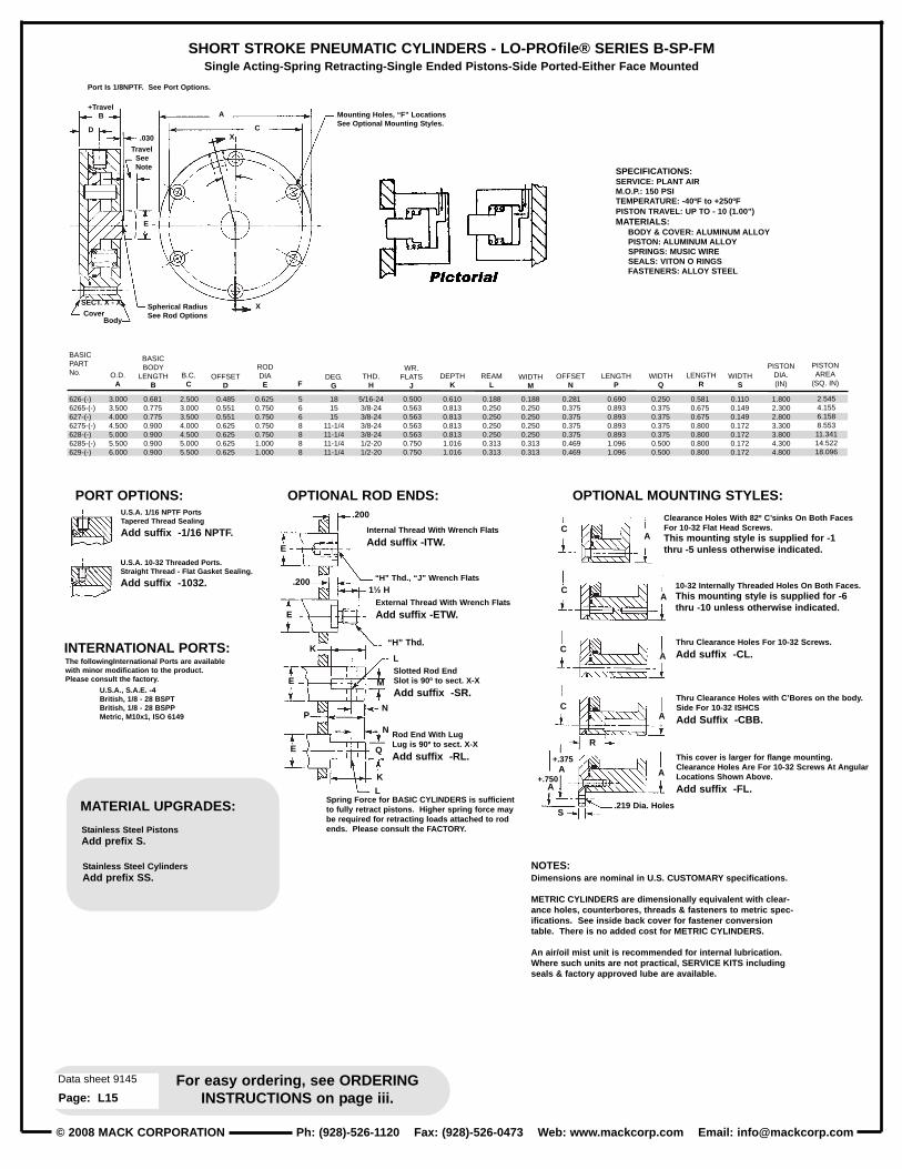
SHORT STROKE PNEUMATIC CYLINDERS - LO-PROfile® SERIES B-SP-FMSingle Acting-Spring Retracting-Single Ended Pistons-Side Ported-Either Face Mounted
NOTES:Dimensions are nominal in U.S. CUST OMARY specifications.
METRIC CYLINDERS are dimensionally equivalent with clear -ance holes, counterbores, threads & fasteners to metric spec -ifications. See inside back cover for fastener conversiontable. There is no added cost for METRIC CYLINDERS.
An air/oil mist unit is recommended for internal lubrication.Where such unit s are not practical, SER VICE KITS includingseals & factory approved lube are available.
+Travel
Port Is 1/8NPTF. See Port Options.
TravelSeeNote
.030
A
C
B
D
E
SECT. X - X X
X
CoverBody
Spherical RadiusSee Rod Options
Mounting Holes, “F” LocationsSee Optional Mounting S tyles.
SPECIFICATIONS:SERVICE: PLANT AIRM.O.P.: 150 PSITEMPERATURE: -40ºF to +250ºFPISTON TRAVEL: UP TO - 10 (1.00”)MATERIALS:
BODY & COVER: ALUMINUM ALLOYPISTON: ALUMINUM ALLOYSPRINGS: MUSIC WIRESEALS: VIT ON O RINGSFASTENERS: ALLOY STEEL
BASICPARTNo.
626-(-)6265-(-)627-(-)6275-(-)628-(-)6285-(-)629-(-)
3.0003.5004.0004.5005.0005.5006.000
0.6810.7750.7750.9000.9000.9000.900
2.5003.0003.5004.0004.5005.0005.500
0.4850.5510.5510.6250.6250.6250.625
0.6250.7500.7500.7500.7501.0001.000
5668888
181515
11-1/411-1/411-1/411-1/4
5/16-243/8-243/8-243/8-243/8-241/2-201/2-20
0.5000.5630.5630.5630.5630.7500.750
0.6100.8130.8130.8130.8131.0161.016
0.1100.1490.1490.1720.1720.1720.172
0.1880.2500.2500.2500.2500.3130.313
0.1880.2500.2500.2500.2500.3130.313
1.8002.3002.8003.3003.8004.3004.800
2.5454.1556.1588.55311.34114.52218.096
0.2810.3750.3750.3750.3750.4690.469
0.6900.8930.8930.8930.8931.0961.096
0.2500.3750.3750.3750.3750.5000.500
0.5810.6750.6750.8000.8000.8000.800
O.D.A
BASICBODY
LENGTHB
B.C.C
OFFSETD
RODDIAE F
DEG.G
THD.H
WR.FLATS
JDEPTH
KWIDTH
SREAM
LWIDTH
M
PISTONDIA.(IN)
PISTONAREA
(SQ. IN)OFFSET
NLENGTH
PWIDTH
QLENGTH
R
Rod End W ith LugLug is 90º to sect. X-X
Add suffix -RL.
Slotted Rod EndSlot is 90º to sect. X-X
Add suffix -SR.
Thru Clearance Holes For 10-32 Screws.
Add suffix -CL.
This cover is larger for flange mounting.Clearance Holes Are For 10-32 Screws At AngularLocations Shown Above.
Add suffix -FL.
Thru Clearance Holes with C’Bores on the body .Side For 10-32 ISHCS
Add Suffix -CBB.
The followingInternational Port s are availablewith minor modification to the product.Please consult the factory .
U.S.A., S.A.E. -4British, 1/8 - 28 BSPTBritish, 1/8 - 28 BSPPMetric, M10x1, ISO 6149
.200
C A
A
A
A
A
C
C
C
R
S .219 Dia. Holes
A
A+.375
+.750
.200 1½ H
“H” Thd., “J” W rench Flat s
“H” Thd.
E
E
K
E
P
Q
N
N
M
E
K
L
L
U.S.A. 1/16 NPTF Port sTapered Thread Sealing
Add suffix -1/16 NPTF .
U.S.A. 10-32 Threaded Port s.Straight Thread - Flat Gasket Sealing.
Add suffix -1032.
Internal Thread W ith W rench Flat s
Add suffix -ITW .
Clearance Holes W ith 82º C’ sinks On Both FacesFor 10-32 Flat Head Screws.This mounting style is supplied for -1thru -5 unless otherwise indicated.
10-32 Internally Threaded Holes On Both Faces.This mounting style is supplied for -6thru -10 unless otherwise indicated.External Thread W ith W rench Flat s
Add suffix -ETW .
Spring Force for BASIC CYLINDERS is sufficientto fully retract pistons. Higher spring force maybe required for retracting loads att ached to rodends. Please consult the F ACTORY.
OPTIONAL ROD ENDS:PORT OPTIONS: OPTIONAL MOUNTING STYLES:
INTERNATIONAL PORTS:
MATERIAL UPGRADES:
Stainless S teel PistonsAdd prefix S.
Stainless S teel CylindersAdd prefix SS.

© 2008 MACK CORPORATIONPh: (928)-526-1120 Fax: (928)-526-0473 Web: www .mackcorp.com Email: [email protected]
For easy ordering, see ORDERINGINSTRUCTIONS on page iii.
Data sheet 9146
Page: L16
SHORT STROKE PNEUMATIC CYLINDERS - LO-PROfile® SERIES B-SP-FMDouble Acting-Single Ended Pistons-Side Ported-Either Face Mounted
NOTES:Dimensions are nominal in U.S. CUST OMARY specifications.METRIC CYLINDERS are dimensionally equivalent with clear -ance holes, counterbores, threads & fasteners to metric speci -fications. See inside back cover for fastener conversion t able.There is no added cost for METRIC CYLINDERS.An air/oil mist unit is recommended for internal lubrication.Where such unit s are not practical, SER VICE KITS includingseals & factory approved lube are available.Cylinders may also be used in low pressure hydraulic and vacuum service.
+ TravelB G
AC
SECT. Y - Y
SECT.X - X
X
H
Y
X
E
Y
J
D
.030
Cover
NOTE: 1/8 NPTF Port s.See Port Options .
“F” Thread 1-1/2 Dia., DepthSee Rod Options.
Body
SPECIFICATIONS:SERVICE: PLANT AIRM.O.P.: 150 PSITEMPERATURE: -40ºF to +250ºFPISTON TRAVEL: UP TO - 20 (2.00”)MATERIALS:
BODY & COVER: ALUMINUM ALLOYPISTON: ALUMINUM ALLOYSEALS: VIT ON O RINGSFASTENERS: ALLOY STEEL
D
CoverBody
G
U.S.A. 1/16 NPTF Port sTapered Thread Sealing
Add suffix -1/16 NPTF .
Port s May be IN-LINE for T ravelsFrom -7 Thru -20
Add suffix -IL.
U.S.A. 10-32 Threaded Port s.Straight Thread - Flat Gasket Sealing.
Add suffix -1032.
Internal Thread W ith W rench Flat s
Add suffix -ITW .
Clearance holes with 82º C’ sinks on both facesFor 10-32 Flat Head Screws.This mounting style is supplied for -1thru -5 unless otherwise indicated.
10-32 internally threaded holes on both faces.This mounting style is supplied for -6thru -20 unless otherwise indicated.
External Thread W ith W rench Flat s
Add suffix -ETW .
.200
C
C
C
C
T
+.375
+.750
.219 Dia. Holes
A
A
U
A
A
A
A
A
E
“F”Thd.“L”W rench
Flats
E
“F”Thd.
M
E
PR
M
Q
P
SE
N
Q
BASICPARTNo.
630-(-)6305-(-)631-(-)6315-(-)632-(-)6325-(-)633-(-)
3.0003.5004.0004.5005.0005.5006.000
0.6810.7750.7750.9000.9000.9000.900
2.5003.0003.5004.0004.5005.0005.500
0.4850.5510.5510.6250.6250.6250.625
0.6250.7500.7500.7500.7501.0001.000
5/16-243/8-243/8-24
7/16-207/16-201/2-201/2-20
0.2970.3240.3240.3750.3750.3750.375
181515
11-1/411-1/411-1/411-1/4
72606045454545
5668888
0.2500.3750.3750.3750.3750.5000.500
0.5000.5630.5630.5630.5630.7500.750
0.6100.8130.8130.8130.8131.0161.016
0.5810.6750.6750.8000.8000.8000.800
0.1100.1490.1490.1720.1720.1720.172
0.1880.2500.2500.2500.2500.3130.313
0.1880.2500.2500.2500.2500.3130.313
0.2810.3750.3750.3750.3750.4690.469
0.6900.8930.8930.8930.8931.0961.096
O.D.A
BASICBODY
LENGTHB
B.CC
PORTOFFSET
D
RODDIAE
RODTHD.
F
PORTOFFSET
GDEG.
HDEG.
J KWIDTH
S
WR.FLATS
LDEPTH
MLENGTH
TWIDTH
UWIDTH
NREAM
P
OFF-SET
QLENGTH
R
Rod End W ith Lug
Add suffix -RL.
Slotted Rod End
Add suffix -SR.
Thru clearance holes for 10-32 screws.
Add suffix -CL.
Thru clearance holes with C’bores on the bodyside for 10-32 I.S.H.C.S.
Add suffix -CBB.
This cover is larger for flange mounting.Clearance holes are for 10-32 screws at angularlocations shown above.
Add suffix -FL.
The following International Port s are availablewith minor modification to the product.Please consult the factory .
U.S.A., S.A.E. -4British, 1/8 - 28 BSPTBritish, 1/8 - 28 BSPPMetric, M10x1, ISO 6149
TravelSee
Note
Mounting Holes, “K” Locations.See Optional Mounting S tyles.
BASICPARTNo.
630-(-)6305-(-)631-(-)6315-(-)632-(-)6325-(-)633-(-)
1.8002.3002.8003.3003.8004.3004.800
2.5454.1556.1588.55311.34114.52218.096
2.2383.7135.7168.111
10.89913.73717.311
PISTONDIA(IN)
EXT.AREA
(SQ.IN.)
RET.AREA
(SQ.IN.)
PISTON DIAMETERS & NET AREAS
.200
1½ “F”
OPTIONAL ROD ENDS:PORT OPTIONS: OPTIONAL MOUNTING STYLES:
INTERNATIONAL PORTS:
MATERIAL UPGRADES:
Stainless S teel PistonsAdd prefix S.
Stainless S teel CylindersAdd prefix SS.

© 2008 MACK CORPORATION Ph: (928)-526-1120 Fax: (928)-526-0473 Web: www .mackcorp.com Email: [email protected]
For easy ordering, see ORDERINGINSTRUCTIONS on page iii.
Data sheet 9147
Page: L17
SHORT STROKE PNEUMATIC CYLINDERS - LO-PROfile® SERIES B-SP-FMDouble Acting-Double Ended Pistons with Thread for Thru Bolts-Side Ported-Either Face Mounted
NOTES:Dimensions are nominal in U.S. CUSTOMARY specifications.METRIC CYLINDERS are dimensionally equivalent with clearanceholes, counterbores, threads & fasteners to metric specifications.See inside back cover for fastener conversion table. There is noadded cost for METRIC CYLINDERS.An air/oil mist unit is recommended for internal lubrication. Wheresuch units are not practical, SERVICE KITS including seals & fac-tory approved lube are available.Cylinders may also be used in low pressure hydraulic and vacuum service.
+ Travel
.030
Cover
B
D
G
E
J
HY
Y
XSECT. X - X
AC
X
SECT. Y - Y
+.030Travel
Clearance over“F” thread.
NOTE: 1/8 NPTF Port s.See Port Options .
“F” Thread Length, 1-1/2 Dia. for -11 thru -20. Threaded forentire length. For -1 thru -10.
Body
SPECIFICATIONS:SERVICE: PLANT AIRM.O.P.: 150 PSITEMPERATURE: -40ºF to +250ºFPISTON TRAVEL: UP TO - 20 (2.00”)MATERIALS:
BODY & COVER: ALUMINUM ALLOYPISTON: ALUMINUM ALLOYSEALS: VIT ON O RINGSFASTENERS: ALLOY STEEL
D
C
C A
A
A
A
C
C
T
+.375
+.750A
A
U
A
CoverBody
G
.219 Dia. Holes.
U.S.A. 1/16 NPTF Port sTapered Thread Sealing
Add suffix -1/16 NPTF .
Port s May be IN-LINE for T ravelsFrom -7 Thru -20
Add suffix -IL.
U.S.A. 10-32 Threaded Port s.Straight Thread - Flat Gasket Sealing.
Add suffix -1032.
Internal Thread W ith W rench Flat s
Add suffix -ITW .
Clearance holes with 82º C’ sinks on both facesFor 10-32 Flat Head Screws.This mounting style is supplied for -1thru -5 unless otherwise indicated.
10-32 internally threaded holes on both faces.This mounting style is supplied for -6thru -20 unless otherwise indicated.
External Thread W ith W rench Flat s
Add suffix -ETW .
BODY
BODY.200
.200
E
“F”Thd.
M
E
P QR
M
Q
E S
N
E
“F” Thd.“L” W rench Flat s
1½ “F”
BASICPARTNo.802-(-)8025-(-)803-(-)8035-(-)804-(-)8045-(-)805-(-)
3.0003.5004.0004.5005.0005.5006.000
0.6810.7750.7750.9000.9000.9000.900
2.5003.0003.5004.0004.5005.0005.500
0.4850.5510.5510.6250.6250.6250.625
0.6250.7500.7500.7500.7501.0001.000
5/16-243/8-243/8-24
7/16-207/16-201/2-201/2-20
0.2970.3240.3240.3750.3750.3750.375
181515
11-1/411-1/411-1/411-1/4
72606045454545
5668888
0.2500.3750.3750.3750.3750.5000.500
0.5000.5630.5630.5630.5630.7500.750
0.6100.8130.8130.8130.8131.0161.016
0.5810.6750.6750.8000.8000.8000.800
0.1100.1490.1490.1720.1720.1720.172
0.1880.2500.2500.2500.2500.3130.313
0.1880.2500.2500.2500.2500.3130.313
0.2810.3750.3750.3750.3750.4690.469
0.6900.8930.8930.8930.8931.0961.096
O.D.A
BASICBODY
LENGTHB
B.CC
PORTOFFSET
D
RODDIAE
RODTHD.
F
PORTOFFSET
GDEG.
HDEG.
J KWIDTH
S
WR.FLATS
LDEPTH
MLENGTH
TWIDTH
UWIDTH
NREAM
P
OFF-SET
QLENGTH
R
Rod End W ith Lug
Add suffix -RL.
Slotted Rod End
Add suffix -SR.
Thru clearance holes for 10-32 screws.
Add suffix -CL.
Thru clearance holes with C’bores on the bodyside for 10-32 I.S.H.C.S.
Add suffix -CBB.
This cover is larger for flange mounting.Clearance holes are for 10-32 screws at angularlocations shown above.
Add suffix -FL.
The following International Port s are availablewith minor modification to the product.Please consult the factory .
U.S.A., S.A.E. -4British, 1/8 - 28 BSPTBritish, 1/8 - 28 BSPPMetric, M10x1, ISO 6149
TravelSee
Note
Mounting Holes, “K” Locations.See Optional Mounting S tyles.
BASICPARTNo.
802-(-)8025-(-)803-(-)8035-(-)804-(-)8045-(-)805-(-)
1.8002.3002.8003.3003.8004.3004.800
2.2383.7135.7168.111
10.89913.73717.311
PISTONDIA.(IN)
NETPISTONAREA
(SQ.IN)
PISTON DIAMETERS & NET AREAS
NOTES - Optional piston rod ends extend from the BODYSIDE and apply to one end only unless otherwise specified.However , pistons may be reversed, (end for end).
If required, add suffix -R. Piston rods have no internal machining on options -ETW , -SR and -RL.
OPTIONAL ROD ENDS:PORT OPTIONS: OPTIONAL MOUNTING STYLES:
INTERNATIONAL PORTS:
MATERIAL UPGRADES:
Stainless S teel PistonsAdd prefix S.
Stainless S teel CylindersAdd prefix SS.

© 2008 MACK CORPORATIONPh: (928)-526-1120 Fax: (928)-526-0473 Web: www .mackcorp.com Email: [email protected]
For easy ordering, see ORDERINGINSTRUCTIONS on page iii.
Data sheet 9148
Page: L18
SHORT STROKE PNEUMATIC CYLINDERS - LO-PROfile® SERIES B-SP-FMDouble Acting-Double Ended Pistons with Thru Hole-Side Ported-Either Face Mounted
+ Travel
.030
E
DB G
A
C
X
H
JY
Y
SECT Y - Y
X
Cover
SECT. X - X
+.030Travel
NOTE: 1/8 NPTF Port s.See Port Options .
“F” Dia., Thru
Body
SPECIFICATIONS:SERVICE: PLANT AIRM.O.P.: 150 PSITEMPERATURE: -40ºF to +250ºFPISTON TRAVEL: UP TO - 20 (2.00”)MATERIALS:
BODY & COVER: ALUMINUM ALLOYPISTON: ALUMINUM ALLOYSEALS: VIT ON O RINGSFASTENERS: ALLOY STEEL
D G
.219 Dia. Holes.
U.S.A. 1/16 NPTF Port sTapered Thread Sealing
Add suffix -1/16 NPTF .
Port s May be IN-LINE for T ravelsFrom -7 Thru -20
Add suffix -IL.
U.S.A. 10-32 Threaded Port s.Straight Thread - Flat Gasket Sealing.
Add suffix -1032.
Clearance holes with 82º C’ sinks on both facesFor 10-32 Flat Head Screws.This mounting style is supplied for -1thru -5 unless otherwise indicated.
10-32 internally threaded holes on both faces.This mounting style is supplied for -6thru -20 unless otherwise indicated.
BASICPARTNo.
806-(-)8065-(-)807-(-)8075-(-)808-(-)8085-(-)809-(-)
3.0003.5004.0004.5005.0005.5006.000
0.6810.7750.7750.9000.9000.9000.900
2.5003.0003.5004.0004.5005.0005.500
0.4850.5510.5510.6250.6250.6250.625
0.6250.7500.7500.7500.7501.0001.000
0.3440.4060.4060.4690.4690.5310.531
0.2970.3240.3240.3750.3750.3750.375
181515
11-1/411-1/411-1/411-1/4
72606045454545
5668888
0.5810.6750.6750.8000.8000.8000.800
0.1100.1490.1490.1720.1720.1720.172
1.8002.3002.8003.3003.8004.3004.800
2.2383.7135.7168.111
10.89913.73717.311
O.D.A
BASICBODY
LENGTHB
B.CC
PORTOFFSET
D
RODDIAE
HOLEF
PORTOFFSET
GDEG.
HDEG.
J KLENGTH
LWIDTH
M
PISTONDIA.(IN)
NETPISTONAREA
(SQ.IN.)
Thru clearance holes for 10-32 screws.
Add suffix -CL.
Thru clearance holes with C’bores on the bodyside for 10-32 I.S.H.C.S.
Add suffix -CBB.
This cover is larger for flange mounting.Clearance holes are for 10-32 screws at angularlocations shown above.
Add suffix -FL.
The followingInternational Port s are availablewith minor modification to the product.Please consult the factory .
U.S.A., S.A.E. -4British, 1/8 - 28 BSPTBritish, 1/8 - 28 BSPPMetric, M10x1, ISO 6149
TravelSee
Note
Mounting Holes, “K” Locations.See Optional Mounting S tyles.
NOTES:Dimensions are nominal in U.S. CUST OMARY specifications.
METRIC CYLINDERS are dimensionally equivalent with clearanceholes, counterbores, threads & fasteners to metric specifications.See inside back cover for fastener conversion t able. There is noadded cost for METRIC CYLINDERS.
An air/oil mist unit is recommended for internal lubrication. Wheresuch unit s are not practical, SER VICE KITS including seals & factoryapproved lube are available.
Cylinders may also be used in low pressure hydraulic and vacuumservice.
Wrench flat s may not be necessary if cylinders can be pressurizedin the retracted or extended position while tightening the rod joint.
Inquiries regarding modifications to BASIC CYLINDERS are alwayswelcome.
CoverBody
Cylinders with THRU HOLE pistons are normallysupplied without wrench flat s.Consult the factory if wrench flat s or othermodification to the piston is required.
CA
CA
CA
C
L
+.375
+.750
A
A
M
A
A
ROD MODIFICATIONS: PORT OPTIONS: OPTIONAL MOUNTING STYLES:
INTERNATIONAL PORTS:
MATERIAL UPGRADES:
Stainless S teel PistonsAdd prefix S.
Stainless S teel CylindersAdd prefix SS.

© 2008 MACK CORPORATION Ph: (928)-526-1120 Fax: (928)-526-0473 Web: www .mackcorp.com Email: [email protected]
For easy ordering, see ORDERINGINSTRUCTIONS on page iii.
Data sheet 9149
Page: L19
SHORT STROKE PNEUMATIC CYLINDERS - LO-PROfile® SERIES B-SP-FMDouble Acting-Double Ended Pistons with Large Hubs-Side Ported-Either Face Mounted
+ Travel
.060
+ .060
Cover
Travel
NOTE: 1/8 NPTF Port s.See Port Options .
Body
E
BD
Y
F
X
G
HY
C
A
X
SECT.Y - Y
SPECIFICATIONS:SERVICE: PLANT AIRM.O.P.: 150 PSITEMPERATURE: -40ºF to +250ºFPISTON TRAVEL: UP TO - 20 (2.00”)
MATERIALS:BODY & COVER: ALUMINUM ALLOYPISTON: ALUMINUM ALLOYSEALS: VIT ON O RINGSFASTENERS: ALLOY STEEL
D FC
A
C
CA
C
+.375
+.750A
A
M
A
L
A
A
.219 Dia. Holes.
U.S.A. 1/16 NPTF Port sTapered Thread Sealing
Add suffix -1/16 NPTF .
Port s May be IN-LINE for T ravelsFrom -7 Thru -20
Add suffix -IL.
U.S.A. 10-32 Threaded Port s.Straight Thread - Flat Gasket Sealing.
Add suffix -1032.
Clearance holes with 82º C’ sinks on both facesFor 10-32 Flat Head Screws.This mounting style is supplied for -1thru -5 unless otherwise indicated.
10-32 internally threaded holes on both faces.This mounting style is supplied for -6thru -20 unless otherwise indicated.
BASICPARTNo.
1085-(-)10855-(-)1084-(-)10845-(-)1083-(-)10835-(-)1082-(-)
3.0003.5004.0004.5005.0005.5006.000
0.6810.7750.7750.9000.9000.9000.900
2.5003.0003.5004.0004.5005.0005.500
0.4850.5510.5510.6250.6250.6250.625
1.0311.0311.6001.6001.8501.8502.600
0.2970.3240.3240.3750.3750.3750.375
181515
11-1/411-1/411-1/411-1/4
72606045454545
5668888
0.7500.7501.1251.1251.3751.3752.000
0.5810.6750.6750.8000.8000.8000.800
0.1100.1490.1490.1720.1720.1720.172
1.8002.3002.8003.3003.8004.3004.800
1.7103.3204.1476.5428.65311.83412.787
O.D.A
BASICBODY
LENGTHB
B.CC
PORTOFFSET
D
RODDIAE
PORTOFFSET
FDEGREES
GDEG.
H JHOLE
KLENGTH
LWIDTH
M
PISTONDIA.(IN)
NETPISTONAREA
(SQ.IN.)
Thru clearance holes for 10-32 screws.
Add suffix -CL.
Thru clearance holes with C’bores on the bodyside for 10-32 I.S.H.C.S.
Add suffix -CBB.
This cover is larger for flange mounting.Clearance holes are for 10-32 screws at angularlocations shown above.
Add suffix -FL.
The followingInternational Port s are availablewith minor modification to the product.Please consult the factory .
U.S.A., S.A.E. -4British, 1/8 - 28 BSPTBritish, 1/8 - 28 BSPPMetric, M10x1, ISO 6149
TravelSee Note
Mounting Holes, “J” Locations.See Optional Mounting S tyles.
NOTES:Dimensions are nominal in U.S. CUST OMARY specifications.
METRIC CYLINDERS are dimensionally equivalent with clearance holes, coun -terbores, threads & fasteners to metric specifications. See inside back coverfor fastener conversion t able. There is no added cost for METRIC CYLINDERS.
An air/oil mist unit is recommended for internal lubrication. Where such unit sare not practical, SER VICE KITS including seals & factory approved lube areavailable.
Cylinders may also be used in low pressure hydraulic and vacuum service.
Wrench flat s may not be necessary if cylinders can be pressurized in theretracted or extended position while tightening the rod joint.
Inquiries regarding modifications to BASIC CYLINDERS are always welcome.
CoverBody
Kmax.
E
Offered with large thru holes.
Add suffix -TH and st atenominal hole diameter withtolerance to plus or minus0.005 inch.If closer tolerance is required, con -sult the factory .Also, consult the factory if counter -bores, special threads or other spe -cial treatment is required.
OPTIONAL PISTON MODIFICATION: PORT OPTIONS: OPTIONAL MOUNTING STYLES:
INTERNATIONAL PORTS:
MATERIAL UPGRADES:
Stainless S teel PistonsAdd prefix S.
Stainless S teel CylindersAdd prefix SS.

© 2008 MACK CORPORATIONPh: (928)-526-1120 Fax: (928)-526-0473 Web: www .mackcorp.com Email: [email protected]
For easy ordering, see ORDERINGINSTRUCTIONS on page iii.
Data sheet 9150
Page: L20
SHORT STROKE PNEUMATIC CYLINDERS - LO-PROfile® SERIES B-SP-FMSingle Acting-Spring Extending-Single Ended Pistons-Side Ported-Either Face Mounted
+ TravelB
D
E
X
G
A
C
X
.060 +Travel
SECT . X - X
Cover
NOTE: 1/8 NPTF Port s.See Port Options .
Body
SPECIFICATIONS:SERVICE: PLANT AIRM.O.P.: 150 PSITEMPERATURE: -40ºF to +250ºFPISTON TRAVEL: UP TO - 10 (1.00”)MATERIALS:
BODY & COVER: ALUMINUM ALLOYPISTON: STAINLESS STEELSPRING: MUSIC WIRESEALS: VIT ON O RINGSFASTENERS: ALLOY STEEL
.219 Dia. Holes.
1-1/2 “F” Depth
1-1/2 “F”
“F” Thd.
E
E
CA
A
A
A
A
A
L
A
C
C
C
K
+.375
+.750
“F” Thread
Spring force for BASIC CYLINDERS is sufficient to fullyextend pistons. Higher spring force may be required wherea load is att ached to the rod. Please consult the factory withyour force requirement s.
.260 +Travel
.260 +Travel
U.S.A. 1/16 NPTF Port sTapered Thread Sealing
Add suffix -1/16 NPTF .
U.S.A. 10-32 Threaded Port s.Straight Thread - Flat Gasket Sealing.
Add suffix -1032.
Clearance holes with 82º C’ sinks on both facesFor 10-32 Flat Head Screws.This mounting style is supplied for -1thru -5 unless otherwise indicated.
10-32 internally threaded holes on both faces.This mounting style is supplied for -6thru -20 unless otherwise indicated.
BASICPARTNo.
S1870-(-)S18705-(-)S1871-(-)S18715-(-)S1872-(-)S18725-(-)S1873-(-)
3.0003.5004.0004.5005.0005.5006.000
0.6810.7750.7750.9000.9000.9000.900
2.5003.0003.5004.0004.5005.0005.500
0.2970.3240.3240.3750.3750.3750.375
1.0311.0311.6001.6001.8501.8502.600
5/16-245/16-243/8-243/8-24
7/16-207/16-201/2-20
181515
11-1/411-1/411-1/411-1/4
5668888
0.7500.7501.0001.0001.2501.2502.000
0.5810.6750.6750.8000.8000.8000.800
0.1100.1490.1490.1720.1720.1720.172
1.8002.3002.8003.3003.8004.3004.800
1.7103.3204.1476.5428.65311.83412.787
O.D.A
BASICBODY
LENGTHB
B.CC
PORTOFFSET
D
RODDIAE
ThreadF
DEG.G H
WR.Flats
JLENGTH
KWIDTH
M
PISTONDIA.(IN)
NETPISTONAREA
(SQ.IN.)
Thru clearance holes for 10-32 screws.
Add suffix -CL.
Thru clearance holes with C’bores on the bodyside for 10-32 I.S.H.C.S.
Add suffix -CBB.
This cover is larger for flange mounting.Clearance holes are for 10-32 screws at angularlocations shown above.
Add suffix -FL.
The followingInternational Port s are availablewith minor modification to the product.Please consult the factory .
U.S.A., S.A.E. -4British, 1/8 - 28 BSPTBritish, 1/8 - 28 BSPPMetric, M10x1, ISO 6149
Mounting Holes, “H” Locations.See Optional Mounting S tyles.
NOTES:Dimensions are nominal in U.S. CUST OMARY specifications.
METRIC CYLINDERS are dimensionally equivalent with clearance holes, counterbores, threads & fas -teners to metric specifications. See inside back cover for fastener conversion t able. There is no addedcost for METRIC CYLINDERS.
An air/oil mist unit is recommended for internal lubrication. Where such unit s are not practical, SER -VICE KITS including seals & factory approved lube are available.
Cylinders may also be used in low pressure hydraulic and vacuum service.
Wrench flat s may not be necessary if cylinders can be pressurized in the retracted or extended positionwhile tightening the rod joint.
Inquiries regarding modifications to BASIC CYLINDERS are always welcome.
“F” Thread
Internal Threads with W rench Flat s.
Add suffix -ITW .
External Threads with W rench Flat s.
Add suffix -ETW .
OPTIONAL ROD ENDS:PORT OPTIONS: OPTIONAL MOUNTING STYLES:
INTERNATIONAL PORTS:
MATERIAL UPGRADES:
Stainless S teel CylindersAdd prefix S.

© 2008 MACK CORPORATION Ph: (928)-526-1120 Fax: (928)-526-0473 Web: www .mackcorp.com Email: [email protected]
For easy ordering, see ORDERINGINSTRUCTIONS on page iii.
Data sheet 9151
Page: L21
SHORT STROKE PNEUMATIC CYLINDERS - LO-PROfile® SERIES B-PR2-SP-FMDouble Acting-Single Ended Pistons-Side Ported-Face Mounted
NOTES:Dimensions are nominal in U.S. CUST OMARY specifications.METRIC CYLINDERS are dimensionally equivalent with clearance holes, counterbores, threads & fasteners tometric specifications. See inside back cover for fastener conversion t able. There is no added cost for MET -RIC CYLINDERS.
An air/oil mist unit is recommended for internal lubrication. Where such unit s are not practical, SER VICEKITS including seals & factory approved lube are available.
Cylinders may also be used in low pressure hydraulic and vacuum service.
Wrench flat s may not be necessary if cylinders can be pressurized in the retracted or extended position whiletightening the rod joint.
Inquiries regarding modifications to BASIC CYLINDERS are always welcome.
+ Travel
.125.375
B
Y
Y
45º 45º
X
X
C
A
F
D
SECT. X - X
SECT. Y - Y
H
Mounting S tructure. See Mounting Options.
“E” ThreadSee Rod Options.
NOTE: 1/8 NPTF Port s.See Port Options .
SPECIFICATIONS:SERVICE: PLANT AIRM.O.P.: 150 PSITEMPERATURE: -40ºF to +250ºFPISTON TRAVEL: UP TO - 20 (2.00”)
MATERIALS:BODY & COVER: ALUMINUM ALLOYPISTON: ALUMINUM ALLOYSEALS: VIT ON O RINGSFASTENERS: ALLOY STEEL
.125
U.S.A. 1/16 NPTF Port sTapered Thread Sealing
Add suffix -1/16 NPTF .
Port s May be IN-LINE for T ravelsFrom -6 Thru -20
Add suffix -IL.
U.S.A. 10-32 Threaded Port s.Straight Thread - Flat Gasket Sealing.
Add suffix -1032 .
Internal Thread W ith W rench Flat s
Add suffix -ITW .
External Thread W ith W rench Flat s
Add suffix -ETW .
BASICPARTNo.
1598-(-)15985-(-)1599-(-)15995-(-)1600-(-)16005-(-)1601-(-)
3.0003.5004.0004.5005.0005.5006.000
0.7500.7500.7501.0001.0001.2501.250
2.5603.0143.5143.9004.4004.8085.308
0.6250.7500.7501.0001.0001.0001.000
5/16-243/8-243/8-241/2-201/2-201/2-201/2-20
0.3980.3980.3980.5230.5230.6480.648
10-321/4-281/4-28
5/16-245/16-243/8-243/8-24
0.6300.5700.5700.7560.7560.9450.945
0.5000.5630.5630.7500.7500.7500.750
0.6100.8130.8131.0161.0161.0161.016
1.9502.3402.8403.1403.6404.0004.500
0.1880.2500.2500.3130.3130.3130.313
0.1880.2500.2500.3130.3130.3130.313
2.9864.3006.3347.744
10.40612.56615.904
2.6793.8585.8926.9599.62111.78115.119
0.2810.3750.3750.4690.4690.4690.469
0.6850.8880.8881.0911.0911.0911.091
0.2500.3750.3750.5000.5000.5000.500
0.3750.3750.3750.5000.5000.6250.625
O.D.A
BASICBODY
LENGTHB
B.CC
RODDIA.
D
RODTHD.
E
PORTOFFSET
F
MNTINGHOLES
GDEPTH
H
WR.FLATS
JDEPTH
K
PISTONDIA.(IN)
WIDTHL
REAMM
EXT.PISTONAREA
(SQ.IN.)
RETR.PISTONAREA
(SQ.IN.)
OFF-SET
NLENGTH
PWIDTH
QWIDTH
R
Rod End W ith Lug
Add suffix -RL.
Slotted Rod End
Add suffix -SR.
The followingInternational Port s are availablewith minor modification to the product.Please consult the factory .
U.S.A., S.A.E. -4British, 1/8 - 28 BSPTBritish, 1/8 - 28 BSPPMetric, M10x1, ISO 6149
TravelSee Note
“G” Mounting Holes.Clearance drilled & C’bored.For Int. Sock. Head Cap Screws.4 Places.See Mounting Options.
User ’sStructure
C
A
A
A
“G” Intrenal Thread, 4 Locations
Internally Threaded Body .
Add suffix -T .
This Coverplate Is Larger for FlangeMounting to Either Side.
Add suffix -FL.
Coverplate Option.
Add suffix -CP .
Clearance Holes For 5/16-24 I.S.H.C.S6 Locations.
“E” Thd.1-1/2 “E” Depth
“E”Thread
Body
.375
D
D
K
LD
M
N
QD
M NP
K
F
User ’sStructure
.125
1 1/2 “E”
C
R
R
A+ .600
+ 1.200A
OPTIONAL ROD ENDS:PORT OPTIONS:OPTIONAL MOUNTING STYLES:
INTERNATIONAL PORTS:
OPTIONAL CONFIGURATIONS:
MATERIAL UPGRADES:
Stainless S teel PistonsAdd prefix S.
Stainless S teel CylindersAdd prefix SS.

© 2008 MACK CORPORATIONPh: (928)-526-1120 Fax: (928)-526-0473 Web: www .mackcorp.com Email: [email protected]
For easy ordering, see ORDERINGINSTRUCTIONS on page iii.
Data sheet 9152
Page: L22
SHORT STROKE PNEUMATIC CYLINDERS - LO-PROfile® SERIES B-PR3-SP-FMSingle Acting-Spring Retracting-Single Ended Pistons-Side Ported-Either Face Mounted
NOTES:Dimensions are nominal in U.S. CUST OMARY specifications.METRIC CYLINDERS are dimensionally equivalent with clearance holes, coun -terbores, threads & fasteners to metric specifications. See inside back coverfor fastener conversion t able. There is no added cost for METRIC CYLINDERS.
An air/oil mist unit is recommended for internal lubrication. Where such unit sare not practical, SER VICE KITS including seals & factory approved lube areavailable.
Cylinders may also be used in low pressure hydraulic and vacuum service.
Inquiries regarding modifications to BASIC CYLINDERS are always welcome.
Spring force for BASIC CYLINDERS is sufficient to fully retract pistons. Higherspring force may be required for retracting loads att ached to rod ends. Pleaseconsult the Factory .
D + Travel
.375
C
.125
E
X
B
45º
X
A
H
F
SECT. X - X
Mounting S tructureSee Mounting Options.
Spherical Radius
See Rod Options
1/8 NPTF Port s. See Port Options .
SPECIFICATIONS:SERVICE: PLANT AIRM.O.P.: 150 PSITEMPERATURE: -40ºF to +250ºFPISTON TRAVEL: UP TO - 10 (1.00”)
MATERIALS:BODY & COVER: ALUMINUM ALLOYPISTON: STAINLESS STEELSPRINGS: MUSIC WIRESEALS: VIT ON O RINGSFASTENERS: ALLOY STEEL
U.S.A. 1/16 NPTF Port sTapered Thread Sealing
Add suffix -1/16 NPTF .
U.S.A. 10-32 Threaded Port s.Straight Thread - Flat Gasket Sealing.
Add suffix -1032.
Internal Thread W ith W rench Flat s
Add suffix -ITW .
External Thread W ith W rench Flat s
Add suffix -ETW .
BASICPARTNo.
S1710-(-)S17105-(-)S1711-(-)S17115-(-)S1712-(-)S17125-(-)S1713-(-)
3.0003.5004.0004.5005.0005.5006.000
2.5603.0143.5143.9004.4004.8085.308
2.5252.9002.9003.4003.4003.5253.525
0.8751.0001.0001.2501.2501.5001.500
1.5001.8751.8752.5002.5003.0003.000
0.6250.7500.7501.0001.0001.0001.000
10-321/4-281/4-28
5/16-245/16-243/8-243/8-24
0.7570.8200.8201.0071.0071.1951.195
0.5000.5630.5630.7500.7500.7500.750
5/16-243/8-243/8-241/2-201/2-201/2-201/2-20
0.3750.3750.3750.5000.5000.6250.625
0.6100.8130.8131.0161.0161.0161.016
0.1880.2500.2500.3130.3130.3130.313
1.9502.3402.8403.1403.6404.0004.500
2.9864.3006.3347.744
10.40612.56615.904
0.1880.2500.2500.3130.3130.3130.313
0.2810.3750.3750.4690.4690.4690.469
0.6850.8880.8881.0911.0911.0911.091
0.2500.3750.3750.5000.5000.5000.500
O.D.A
B.C.B
BODYLENGTH
C
SHOULDERLENGTH
D
BOSSDIA.
E
RODDIA.
F
MNTINGHOLES
GDEPTH
H
WR.FLATS
JTHREAD
KWIDTH
SLENGTH
LREAM
M
PISTONDIA.(IN.)
PISTONAREA
(SQ.IN.)WIDTH
N
OFF-SETP
LENGTHQ
WIDTHR
Rod End W ith Lug
Add suffix -RL.
Slotted Rod End
Add suffix -SR.
The following International Port s are availablewith minor modification to the product.Please consult the factory .
U.S.A., S.A.E. -4British, 1/8 - 28 BSPTBritish, 1/8 - 28 BSPPMetric, M10x1, ISO 6149
TravelSee Note
“G” Mounting Holes.Clearance drilled & C’bored.For Int. Sock. Head Cap Screws.4 Places.See Mounting Options.
User ’sStructure
B A
A
A
S
S
B
A
A+1.200
+.600This Coverplate Is Larger for FlangeMounting to Either Side.
Add suffix -FL.
Coverplate Option.
Add suffix -CP .
Internally Threaded Body .
Add suffix -T .
“G” Internal Thread4 Locations
Clearance Holes For 5/16-24 I.S.H.C.S.6 Locations.
.125
.125
F
F
L
F N
Q
F R
L
M
P
P
M
“K” Thd., 1-1/2 Dia., Depth1-1/2 “K”
“K” Thread
OPTIONAL ROD ENDS:PORT OPTIONS: OPTIONAL MOUNTING STYLES:
INTERNATIONAL PORTS:OPTIONAL CONFIGURATIONS:
MATERIAL UPGRADES:
Stainless S teel CylindersAdd prefix S.

© 2008 MACK CORPORATION Ph: (928)-526-1120 Fax: (928)-526-0473 Web: www .mackcorp.com Email: [email protected]
For easy ordering, see ORDERINGINSTRUCTIONS on page iii.
Data sheet 9714
Page: L23
SHORT STROKE PNEUMATIC CYLINDERS - LO-PROfile® SERIES A-EP-PMSingle Acting-Spring Retracting-Single Ended Pistons-End Ported-Pocket Mounted
BASICPARTNo.
6007-(-)6008-(-)6009-(-)6010-(-)6011-(-)6012-(-)6013-(-)
1.0001.2501.5001.7502.0002.2502.500
0.6880.9381.1881.4381.6881.9382.188
0.2500.2500.3750.3750.6250.6250.625
4-404-40
10-3210-32
5/16-245/16-245/16-24
0.1880.1880.2810.2810.5000.5000.500
Table 1Table 10.4560.4560.9310.9310.931
0.4500.5000.8130.8131.1251.1251.125
0.3850.3850.4860.4860.6900.6900.690
0.1410.1410.1880.1880.2810.2810.281
0.3050.3050.4060.4060.6100.6100.610
0.0940.0940.1250.1250.1880.1880.188
0.0630.0630.1250.1250.1880.1880.188
0.1560.1560.1880.1880.2500.2500.250
0.4500.5750.7000.9601.2001.4501.700
0.1590.2600.3850.7091.1311.8512.270
O.D.A
BOLTCIRCLE
B
RODDIA.
CTHD.
F
WR.FLATS
G
BOSSLENGTH
E
BOSSDIA.
DLENGTH
H
OFF-SET
KDEPTH
JREAM
LWIDTH
MWIDTH
N
PISTONO.D.(IN.)
EXTENDPISTONAREA
(SQ. IN)
TABLE 1
PART NO. E
6007 -1 Thru -3 0.2316008 -1 Thru -3 0.2316007 -4 Thru -6 0.3816008 -4 Thru -6 0.3816007 -7 Thru -10 0.572 6008 -7 Thru -10 0.572
Barbed FittingFor 1/8 I.D. Hose.Fitting is furnished
Thru clearance holes withcounterbores for no. 4-40I.S.H.C.S. Depth shown.4 Places for mounting.See mounting options.
Spherical Rad.See Rod Options
.030
A
B
DC
E
Pictorial
Z
Z
.480
Travel
Sect. Z - Z
PRODUCT DETAILS
OPTIONAL ROD ENDS: OPTIONAL MOUNTING STYLES:
SUGGESTED MOUNTING DETAILS
Internal Thread W ith W renchFlats.
Add suffix -ITW .
Extrnal Thread W ith W rench Flat s.
Add suffix -ETW .
Slotted Rod End.
Add suffix -SR.
Rod End W ith Lug.
Add suffix -RL.
4-40 internally threaded holes at four locations in both front and rear faces.
Add suffix -FR.
This cover is larger for flange mountingto either side with clearance holes for4-40 screws at four locations.
Add suffix -FL.
For mounting directly to a USER’S structure.This configuration provides the lowest profileby eliminating the cover . Porting is incorporatedinto the user ’s structure. A face seal is furnishedfor sealing between the structure and cylinderbody . Clearance holes with counterbores for 4-40internal socket head cap screws are in the body atfour locations.
Add suffix -TC.
.580 +Travel
SPECIFICATIONS:SERVICE: PLANT AIRM.O.P.: 300 PSITEMPERATURE: -40ºF to +250ºFPISTON TRAVEL: UP TO - 10 (1.00”)
MATERIALS:BODY & COVER: ALUMINUM ALLOYPISTON: ALUMINUM ALLOYSPRINGS: MUSIC WIRE OR STAINLESS STEELSEALS: VIT ON O RINGSFASTENERS: ALLOY STEEL
NOTES:Dimensions are nominal in U.S. CUST OMARY specifications.Metric cylinders are dimensionally equivalent except for conversion in mounting det ails where, threads, fasten -ers, clearance holes & counterbores are to metric st andards. See inside back cover for a t able of metric fasten -er conversion. There is no added cost for metric cylinders. An air/oil mist unit is recommended for internallubrication. Where such unit s are not practical, service kit s including seals and factory aproved lubricant areavailable. S pring force for basic cylinders is sufficient to fully retract pistons. Inquiries regarding modificationsto BASIC CYLINDERS are always welcome.
+.005- .000
A
B + .005Bolt Circle
WorkZone
Pilot Dia.
B Minus .250
Drill & T ap For No. 4-40 Thd.4 Places For Mounting
User ’sMounting S tructure
This area is free of lines & fittings
.050 Min.
.200
.200Length1-1/2 Dia.
F Thd.G Wr. Flats
F Thd.Depth 1-1/2 Dia.
0.580+Travel
0.386+Travel
MountingStructure
0.580 +Travel
G
C
C
C
JL
M
K
JH
N
K
L
AB
A
AB
AA
+.250+.500
.286
C
Cover.144
Face Seal
MATERIAL UPGRADES:
Stainless S teel PistonsAdd prefix S.
Stainless S teel CylindersAdd prefix SS.

© 2008 MACK CORPORATIONPh: (928)-526-1120 Fax: (928)-526-0473 Web: www .mackcorp.com Email: [email protected]
For easy ordering, see ORDERINGINSTRUCTIONS on page iii.
Data sheet 9715
Page: L24
SHORT STROKE PNEUMATIC CYLINDERS - LO-PROfile® SERIES A-ETI-PMSingle Acting-Spring Retracting-Single Ended Pistons-End T repanned Inlet-Pocket Mounted
BASICPARTNo.
6000-(-)6001-(-)6002-(-)6003-(-)6004-(-)6005-(-)6006-(-)
1.0001.2501.5001.7502.0002.2502.500
0.6880.9381.1881.4381.6881.9382.188
0.2500.2500.3750.3750.6250.6250.625
4-404-40
10-3210-32
5/16-245/16-245/16-24
0.1880.1880.2810.2810.5000.5000.500
Table 1Table 10.4560.4560.9310.9310.931
0.4500.5000.8130.8131.1251.1251.125
0.3850.3850.4860.4860.6900.6900.690
0.1410.1410.1880.1880.2810.2810.281
0.3050.3050.4060.4060.6100.6100.610
0.0940.0940.1250.1250.1880.1880.188
0.0630.0630.1250.1250.1880.1880.188
0.1560.1560.1880.1880.2500.2500.250
0.4500.5750.7000.9601.2001.4501.700
0.1590.2600.3850.7091.1311.6512.270
O.D.A
BOLTCIRCLE
B
RODDIA.
CTHD.
F
WR.FLATS
G
BOSSLENGTH
E
BOSSDIA.
DLENGTH
H
OFF-SET
KDEPTH
JREAM
LWIDTH
MWIDTH
N
PISTONO.D.(IN.)
EXTENDPISTONAREA
(SQ. IN)
TABLE 1
PART NO. E
6000 -1 Thru -3 0.2316001 -1 Thru -3 0.2316000 -4 Thru -6 0.3816001 -4 Thru -6 0.3816000 -7 Thru -10 0.572 6001 -7 Thru -10 0.572
Trepanned Face Seal“O” ring is furnished.
Thru clearance holes withcounterbores for no. 4-40I.S.H.C.S. Depth shown.4 Places for mounting.See mounting options.
Sph. Rad. (See Rod Options)
.030
DC
E
Sect. Z - Z
Pictorial
PRODUCT DETAILS
OPTIONAL ROD ENDS: OPTIONAL MOUNTING STYLES:
SUGGESTED MOUNTING DETAILS
A
BZ
Z
.480
A
B
+ .005- .000
+ .005
Travel
Internal Thread W ith W renchFlats.
Add suffix -ITW .
Extrnal Thread W ith W rench Flat s.
Add suffix -ETW .
Slotted Rod End.
Add suffix -SR.
Rod End W ith Lug.
Add suffix -RL.
#4-40 internally threaded holes at four locations in both front and rear faces.
Add suffix -R.
This cover is larger for flange mountingto either side with clearance holes for4-40 screws at four locations.
Add suffix -FL.
For mounting directly to a USER’S structure.This configuration provides the lowest profileby eliminating the cover . Porting is incorpo -rated into the user ’s structure. A face seal isfurnished for sealing between the structureand cylinder body . Clearance holes with coun -terbores for 4-40 internal socket head capscrews are in the body at four locations.
Add suffix -TC.
.580 +Travel
SPECIFICATIONS:SERVICE: PLANT AIRM.O.P.: 300 PSITEMPERATURE: -40ºF to +250ºFPISTON TRAVEL: UP TO - 10 (1.00”)
MATERIALS:BODY & COVER: ALUMINUM ALLOYPISTON: ALUMINUM ALLOYSPRINGS: MUSIC WIRE OR STAINLESS STEELSEALS: VIT ON O RINGSFASTENERS: ALLOY STEEL
NOTES:Dimensions are nominal in U.S. CUST OMARY specifications.Metric cylinders are dimensionally equivalent except for conversion in mounting det ails where, threads, fasten -ers, clearance holes & counterbores are to metric st andards. See inside back cover for a t able of metric fasten -er conversion. There is no added cost for metric cylinders. An air/oil mist unit is recommended for internallubrication. Where such unit s are not practical, service kit s including seals and factory aproved lubricant areavailable. S pring force for basic cylinders is sufficient to fully retract pistons. Inquiries regarding modificationsto BASIC CYLINDERS are always welcome.
PilotDia.
“O” ring seal.(furnished)
FlowPassage.
User ’s Mounting Structure.
Drill & T ap For No. 4-40 Thd.4 Places For Mounting
Drill 7/64 (.109)To intersect flow p assagein mounting structure.
This area is free of lines & fittings
.050 Min.WorkZone
.200
.200
G
C
C
C
JL
M
K
J
K
L
N C
AB
H
Length1-1/2 Dia.
F Thd.G Wr. Flats
F Thd.Depth 1-1/2 Dia.
0.580+Travel
0.386+Travel
0.286
MountingStructure
0.580 +Travel
Cover.144
Face Seal
AA
A
AB
+ .500+ .250
MATERIAL UPGRADES:
Stainless S teel PistonsAdd prefix S.
Stainless S teel CylindersAdd prefix SS.

© 2008 MACK CORPORATION Ph: (928)-526-1120 Fax: (928)-526-0473 Web: www .mackcorp.com Email: [email protected]
For easy ordering, see ORDERINGINSTRUCTIONS on page iii.
Data sheet 9716
Page: L25
SHORT STROKE PNEUMATIC CYLINDERS - LO-PROfile® SERIES A-ETI-PMDouble Acting-Single Ended Pistons-End T repanned Inlets-Pocket Mounted
BASICPARTNo.
6014-(-)6015-(-)6016-(-)6017-(-)6018-(-)6019-(-)6020-(-)
1.0001.2501.5001.7502.0002.2502.500
0.6880.9381.1881.4381.6881.9382.188
0.2500.3130.3750.5000.6250.6250.625
2224444
4-4010-3210-321/4-28
5/16-245/16-245/16-24
.330
.392
.464
.590
.714
.840
.965
00000045454545
.188
.250
.281
.375
.500
.500
.500
.385
.385
.486
.690
.690
.690
.690
0.3050.3050.4060.6100.6100.6100.610
.141
.141
.188
.281
.281
.281
.281
0.0940.0940.1250.1880.1880.1880.188
0.0630.0940.1250.1880.1880.1880.188
0.1560.1560.1880.2500.2500.2500.250
0.4500.5750.7000.9501.2001.4501.700
0.1590.2600.3850.7091.1311.6512.270
0.1100.1830.2750.5130.8241.3441.963
O.D.A
BOLTCIRCLE
B
RODDIA.
C
NO.PLCS.
FDIM.
GDEG.
E
RODTHD.
D
WR.FLATS
HLENGTH
KDEPTH
J
OFFSET
LREAM
MWIDTH
NWIDTH
O
PISTONO.D.(IN.)
EXTENDPISTONAREA
(SQ. IN)
RETRACTPISTONAREA
(SQ. IN)
D Thd.1-1/2 Dia.,DepthSee Rod Options
Trepanned face seal.Seal is furnished.2 Places.
For Mounting:CL. Drilled & C’bored for6-32 slotted round headmachine screws. (See Note 1)“F” places.See Mounting Option.
.030
Internal Thread W ith W renchFlats.
Add suffix -ITW .
Extrnal Thread W ith W rench Flat s.
Add suffix -ETW .
Slotted Rod End.
Add suffix -SR.
Rod End W ith Lug.
Add suffix -RL.
+Travel.580
SPECIFICATIONS:SERVICE: PLANT AIRM.O.P.: 300 PSITEMPERATURE: -40ºF to +250ºFPISTON TRAVEL: UP TO - 20 (2.00”)
MATERIALS:BODY & COVER: ALUMINUM ALLOYPISTON: ALUMINUM ALLOYSEALS: VIT ON O RINGSFASTENERS: ALLOY STEEL
NOTES:Dimensions are nominal in U.S. CUST OMARY specifications.Metric cylinders are dimensionally equivalent except for conversion in mounting det ails where,threads, fasteners, clearance holes & counterbores are to metric st andards. See inside backcover for a t able of metric fastener conversion. There is no added cost for metric cylinders.An air/oil mist unit is recommended for internal lubrication. Where such unit s are not practi -cal, service kit s including seals and factory aproved lubricant are available. S pring force forbasic cylinders is sufficient to fully retract pistons. Inquiries regarding modifications to BASICCYLINDERS are always welcome.
PilotDia.
+ .005B
G
G
E
Pictorial
+ .005- .000
A “O” ring seal.(furnished)
FlowPassage.
User ’s Mounting Structure.
Drill & T ap For No. 6-32 Thd.at “F location. See mounting option.
This area is free of lines & fittings
.050 Min.WorkZone
.200
.2001-1/2Thd.
Length
D Thd.
C
C
J
C
H
M
N
LK
J
O C
L
M
H. W. F.
D Thd.1-1/2 Dia. Dp.
0.580+Travel
TravelA
Z X
X E
Z
PRODUCT DETAILS
OPTIONAL MOUNTING STYLE: OPTIONAL ROD ENDS:
SUGGESTED MOUNTING DETAILS
Sect. X-X
B
CG
G
Sect. Z-Z
Drill 7/64 (.109)To intersect flow p assagein mounting structure.
2 places.
(thrust force = area times pressure
NOTE 1: 6-32 Slotted Round Head Machine Screws W ith Lengths T o 3 InchesAre Available From Most Industrial Supply Distributors.
4-40 internally threaded holes at “F”locations in the rear face only .
Add suffix -R.Intended as an option where attachment s to the rear face is preferred.
B A
MATERIAL UPGRADES:
Stainless S teel PistonsAdd prefix S.
Stainless S teel CylindersAdd prefix SS.

© 2008 MACK CORPORATIONPh: (928)-526-1120 Fax: (928)-526-0473 Web: www .mackcorp.com Email: [email protected]
For easy ordering, see ORDERINGINSTRUCTIONS on page iii.
Data sheet 9717
Page: L26
SHORT STROKE PNEUMATIC CYLINDERS - LO-PROfile® SERIES A-ETI-PMDouble Acting-Double Ended Pistons W ith Internal Thread-End T repanned Inlets-Pocket Mounted
BASICPARTNo.
6021-(-)6022-(-)6023-(-)6024-(-)6025-(-)6026-(-)6027-(-)
1.0001.2501.5001.7502.0002.2502.500
0.6880.9381.1881.4381.6881.9382.188
0.2500.3130.3750.5000.6250.6250.625
2224444
4-4010-3210-321/4-28
5/16-245/16-245/16-24
0.3300.3920.4640.5900.7140.8400.965
00000045454545
0.1880.2500.2810.3750.5000.5000.500
0.3850.3850.4860.6900.6900.6900.690
0.3050.3050.4060.6100.6100.6100.610
0.1410.1410.1880.2810.2810.2810.281
0.0940.0940.1250.1880.1880.1880.188
0.0630.0940.1250.1880.1880.1880.188
0.1560.1560.1880.2500.2500.2500.250
0.4500.5750.7000.9501.2001.4501.700
0.1100.1830.2750.5130.8241.3441.963
O.D.A
BOLTCIRCLE
B
RODDIA.
C
NO.PLCS.
FDIM.
GDEG.
E
RODTHD.
D
WR.FLATS
HLENGTH
KDEPTH
J
OFFSET
LREAM
MWIDTH
NWIDTH
O
PISTONO.D.(IN.)
NETPISTONAREA
(SQ. IN)
D Thd.1-1/2 Dia.,DepthSee Rod Options
Trepanned face seal.Seal is furnished.2 Places.
For Mounting:CL. Drilled & C’bored for6-32 slotted round headmachine screws. (See Note 1)“F” places.See Mounting Option.
.030
A
Z
Sect. X-X
X
X
ZB
PRODUCT DETAILS
OPTIONAL MOUNTING STYLE: OPTIONAL ROD ENDS:
SUGGESTED MOUNTING DETAILS
E
CG
G
Sect. Z-Z
Internal Thread W ith W renchFlats.
Add suffix -ITW .
Extrnal Thread W ith W rench Flat s.
Add suffix -ETW .
Slotted Rod End.
Add suffix -SR.
Rod End W ith Lug.
Add suffix -RL.
BA
+Travel.580
SPECIFICATIONS:SERVICE: PLANT AIRM.O.P.: 300 PSITEMPERATURE: -40ºF to +250ºFPISTON TRAVEL: UP TO - 20 (2.00”)
MATERIALS:BODY & COVER: ALUMINUM ALLOYPISTON: ALUMINUM ALLOYSEALS: VIT ON O RINGSFASTENERS: ALLOY STEEL
NOTES:Dimensions are nominal in U.S. CUST OMARY specifications.Metric cylinders are dimensionally equivalent except for conversion in mounting det ails where,threads, fasteners, clearance holes & counterbores are to metric st andards. See inside back cover fora table of metric fastener conversion. There is no added cost for metric cylinders. An air/oil mist unitis recommended for internal lubrication. Where such unit s are not practical, service kit s includingseals and factory aproved lubricant are available. W rench flat s may not be necessary if cylinders canbe pressurized in the extended or retracted position while tightening the rod connection. Inquiriesregarding modifications to BASIC CYLINDERS are always welcome.
PilotDia.
+ .005 /-.000A
+ .005B
E
G
G
“O” ring seal.(2) furnished
FlowPassage.
User ’s Mounting Structure.
Drill & T ap For No. 6-32 Thd.at “F location. See mounting option.
This area is free of lines & fittings
.050 Min.WorkZone
.200
.200
H
C
C
C
M
N
L
JK
CO
L
M
1-1/2Thd.
Length
D Thd.H. W. F.
D Thd.1-1/2 Dia. Dp.
0.580+Travel
Travel
Drill 7/64 (.109)To intersect flow p assagein mounting structure.
2 places.
(thrust force = area times pressure
NOTE 1: 6-32 Slotted Round Head Machine Screws W ith Lengths T o 3 InchesAre Available From Most Industrial Supply Distributors.
C +.020 Min.
Clearance OverThread “D”
NOTE: Optional piston rod ends extend from the COVER SIDEand apply to one end only unless otherwise specified.However , cylinders may be disassembled and pistons can bereversed. (end for end)Optional pistons are solid except for machining shown above.
4-40 internally threaded holes at “F”locations in the rear face only .
Add suffix -R.Intended as an option where attachment s to the rear face is preferred.
MATERIAL UPGRADES:
Stainless S teel PistonsAdd prefix S.
Stainless S teel CylindersAdd prefix SS.

© 2008 MACK CORPORATION Ph: (928)-526-1120 Fax: (928)-526-0473 Web: www .mackcorp.com Email: [email protected]
For easy ordering, see ORDERINGINSTRUCTIONS on page iii.
Data sheet 9718
Page: L27
SHORT STROKE PNEUMATIC CYLINDERS - LO-PROfile® SERIES A-ETI-PMDouble Acting-Double Ended Pistons W ith Thru Hole-End T repanned Inlets-Pocket Mounted
BASICPARTNo.
6035-(-)6036-(-)6037-(-)6038-(-)6039-(-)6040-(-)6041-(-)
1.0001.2501.5001.7502.0002.2502.500
0.6880.9381.1881.4381.6881.9382.188
0.2500.3130.3750.5000.6250.6250.625
2224444
0.1290.2060.2060.2810.3440.3440.344
0.3300.3920.4640.5900.7140.8400.965
00000045454545
0.4500.5750.7000.9501.2001.4501.700
0.1100.1830.2750.5131.8241.3441.963
O.D.A
BOLTCIRCLE
B
RODDIA.
C
NO.PLCS.
FDIM.
GDEG.
E
HOLEDIA.
D
PISTONO.D.(IN.)
NETPISTONAREA
(SQ. IN)
D Thd.1-1/2 Dia.,DepthSee Rod Options
Trepanned face seal.Seal is furnished.2 Places.
For Mounting:CL. Drilled & C’bored for6-32 slotted round headmachine screws. (See Note 1)“F” places.See Mounting Option.
.030
+Travel.580
SPECIFICATIONS:SERVICE: PLANT AIRM.O.P.: 300 PSITEMPERATURE: -40ºF to +250ºFPISTON TRAVEL: UP TO - 20 (2.00”)
MATERIALS:BODY & COVER: ALUMINUM ALLOYPISTON: ALUMINUM ALLOYSEALS: VIT ON O RINGSFASTENERS: ALLOY STEEL
NOTES:Dimensions are nominal in U.S. CUST OMARY specifications.Metric cylinders are dimensionally equivalent except for conversion in mounting det ailswhere, threads, fasteners, clearance holes & counterbores are to metric st andards. Seeinside back cover for a t able of metric fastener conversion. There is no added cost formetric cylinders. An air/oil mist unit is recommended for internal lubrication. Wheresuch unit s are not practical, service kit s including seals and factory aproved lubricantare available. W rench flat s may not be necessary if cylinders can be pressurized in theextended or retracted position while tightening the rod connection. Inquiries regardingmodifications to BASIC CYLINDERS are always welcome.
PilotDia.
“O” ring seal.(2) furnished
FlowPassages
User ’s Mounting Structure.
SUGGESTED MOUNTING DETAILSPRODUCT DETAILS
Drill & T ap For No. 6-32 Thd.at “F location. See mounting option.
This area is free of lines & fittings
.050 Min.
C +.020 (MIN.)
WorkZone
0.580+Travel
B A
TravelA
Z X
EX
BZ
CG
G
A+.005 / -.000 +.005
B
G
G
E
Sect. X- X
Sect. Z- Z
Drill 7/64 (.109)To intersect flow p assagein mounting structure.
2 places.
(thrust force =net piston area times pressure)
NOTE 1: 6-32 Slotted Round Head Machine Screws W ith Lengths T o 3 InchesAre Available From Most Industrial Supply Distributors.
NOTE: Optional piston rod ends extend from the COVER SIDEand apply to one end only unless otherwise specified.However , cylinders may be disassembled and pistons can bereversed. (end for end)Optional pistons are solid except for machining shown above.
ROD MODIFICATION:
OPTIONAL MOUNTING STYLE:
Cylinders with THRU HOLE pistons are normally suppliedas shown. Please consult the Factory if wrench flat s orother modification to the piston is required.
4-40 Internally threaded holes at “F”locations in the rear face only .
Add suffix -R.Intended as an option where att achmentto the rear face is preferred.
MATERIAL UPGRADES:
Stainless S teel PistonsAdd prefix S.
Stainless S teel CylindersAdd prefix SS.

©Ph: (928)-526-1120 Fax: (928)-526-0473
For easy ordering, see ORDERINGINSTRUCTIONS on page iii.
Data sheet 9710
Page: L28
Ph: (928)-526-1120 Fax: (928)-526-0473 Web: www .mackcorp.com Email: [email protected]
SHORT STROKE PNEUMATIC CYLINDERS - LO-PROfile® SERIES A-MR-RAMSSingle Acting-Single Ended Manual Reset Pistons-End Ported-Side Mounted
BASICPARTNo.
6086-56087-56088-56089-5
0.5000.6250.7500.875
0.7500.8751.0001.125
0.4800.5600.6000.725
4-404-408-328-32
6-32X7/88-32X1
10-32X1-1/410-32X1-3/8
0.5320.6000.6600.750
0.1960.3070.4420.601
15253550
A(IN.)
B(IN.)
C(IN.)
Int.Threads
FE
(IN.)
MountingScrews
D
PISTONAREA
(SQ.IN.)
FORCE@80 PSI
(LB.)
APPLICATIONSLOW COST RAMS FOR POWER CLAMPING AND WORK HOLDING IN JIGS AND FIXTURESUSING PLANT AIR AS A SOURCE OF PRESSURE.
DESCRIPTION: AIR PRESSURE EXTENDS THE PISTON FOR CLAMPING AND HOLDING. WHEN PRESSURE ISRELEASED, THE PISTON CAN BE RETRACTED MANUALLY. MOUNTING IS TO THE LOWER FACE AND PORTINGIS AT THE REAR FACE.
DESCRIPTION: Same as the face mounted version except mounting and porting is at the rear face.
DESCRIPTION: A spring is cont ained inside the piston to provide a small mechanical forcefor holding a work piece in proper position before applying pressure.
DESCRIPTION: Nose options thread directly into the t apped hole in the piston.
BASIC FACE MOUNTED VERSION
2.2500.050
0.250
1/4-20 Thd.
10-32 Port
0.220
C
0.500Travel
ADia.
RetractPIN
MountingStructure
BSquare
Cl. Drilled For“D” Size Screws2 Places
SPECIFICATIONS: SERVICE: PLANT AIRM.O.P.: 150 PSIPISTON TRAVEL: UP TO - 20 (2.00”)
MATERIALS:ALUMINUM ALLOY
OPTIONAL END MOUNTING
OPTIONAL PRELOADED PISTON
OPTIONAL NOSE FITTINGS
MountingStructure
.313 Thru holefor clearanceover fitting
F internal thd.2 places
PreloadSpring
E
0.225
0.156
0.225
90ºCone
0.188RAD.
VEE NOSE OPTION (SUFFIX -VN)
FLAT NOSE OPTION (SUFFIX -FN)
RADIUS NOSE OPTION (SUFFIX -RN)
NOTE: Part s are shipped with the basic 1/4-20 internal thread in thepiston if no option is specified.
END MOUNTED OPTION:Add Suffix -EM.
PRELOAD OPTION:Add Suffix -PP
NOSE OPTION:Add Suffix -VN, -FN or -RN.

© 2008 MACK CORPORATION Ph: (928)-526-1120 Fax: (928)-526-0473 Web: www .mackcorp.com Email: [email protected]
For easy ordering, see ORDERINGINSTRUCTIONS on page iii.
Data sheet 9711
Page: L29
SHORT STROKE PNEUMATIC CYLINDERS - LO-PROfile® SERIES A-MR-RAMSSingle Acting-Single Ended Manual Reset Pistons-Side T repanned Inlets-Side Mounted
BASICPARTNo.
6090-56091-56092-56093-5
0.5000.6250.7500.875
0.7500.8751.0001.125
0.4800.5600.6000.725
4-404-408-328-32
6-32X7/88-32X1
10-32X1-1/410-32X1-3/8
0.5320.6000.6600.750
0.1960.3070.4420.601
15253550
A(IN.)
B(IN.)
C(IN.)
Int.Threads
F
E(IN.)
MountingScrews
D
PISTONAREA
(SQ.IN.)
FORCE@80 PSI
(LB.)
APPLICATIONSLOW COST RAMS FOR POWER CLAMPING AND WORK HOLDING IN JIGS AND FIXTURESUSING PLANT AIR AS A SOURCE OF PRESSURE.
DESCRIPTION: AIR PRESSURE EXTENDS THE PISTON FOR CLAMPING AND HOLDING. WHEN PRESSURE ISRELEASED, THE PISTON CAN BE RETRACTED MANUALLY. BODIES INCORPORATE A TREPANNED GROOVEWITH AN “O” RING FACE SEAL FOR PORTING DIRECTLY TO THE USER’S MOUNTING STRUCTURE. FEED LINESAND FITTINGS ARE LOCATED IN THIS MOUNTING STRUCTURE BELOW THE MOUNTING PLANE TO CLEAR THEWORK AREA AND TO AVOID ACCIDENTAL DAMAGE TO SUPPLY LINES.
DESCRIPTION: Same as the manifold version except mounting and porting is at the aft end. Internal threads and provisions for face sealing is on the af t face of ram.
DESCRIPTION: A spring is cont ained inside the piston to provide a small mechanical forcefor holding a work piece in proper position before applying pressure.
DESCRIPTION: Nose options thread directly into the t apped hole in the piston.
BASIC MANIFOLD MOUNTED VERSION
2.250
0.250
1/4-20 THD.
TREPAN PORT“O” Ring Supplied
CL. Drilled For“D” Size Screws2 Places forMounting
0.220
RETRACTPIN
0.500Travel
ADia.
0.050 0.400
MountingStructure
BSquare
Drill .109in user ’s manifoldfor airtransfer
OPTIONAL END MOUNTING
OPTIONAL PRELOAD PISTON
OPTIONAL NOSE FITTINGS
MountingStructure
Trepan Port“O” Ring Supplied
Drill .109 INUser ’s manifold
F internal thd. 2 places
PreloadSpring
E
END MOUNTED OPTION:Add Suffix -EM.
PRELOAD OPTION:Add Suffix -PP
NOSE OPTION:Add Suffix -VN, -FN or -RN.0.225
0.156
0.225
90ºCone
0.188RAD.
VEE NOSE OPTION (SUFFIX -VN)
FLAT NOSE OPTION (SUFFIX -FN)
RADIUS NOSE OPTION (SUFFIX -RN)
NOTE: Part s are shipped with the basic 1/4-20 internal thread in thepiston if no option is specified.
C
SPECIFICATIONS:SERVICE: PLANT AIRM.O.P.: 150 PSI
MATERIALS: ALUMINUM ALLOY

© 2008 MACK CORPORATIONPh: (928)-526-1120 Fax: (928)-526-0473 Web: www .mackcorp.com Email: [email protected]
For easy ordering, see ORDERINGINSTRUCTIONS on page iii.
Data sheet 9712
Page: L30
SHORT STROKE PNEUMATIC CYLINDERS - LO-PROfile® SERIES A-SPR-RAMSSingle Acting-Spring Retracted-Single Ended Pistons-End Ported-Side Mounted
BASICPARTNo.
5701-55702-55703-55704-5
0.3130.4380.4380.562
0.7500.8751.0001.125
0.4800.5600.6000.725
4-404-408-328-32
0.5000.6250.7600.875
10-321/4-201/4-201/4-20
6-32X7/88-32X1
10-32X1-1/410-32X1-3/8
0.5320.6000.6600.750
0.1960.3070.4420.601
10.218.427.641.3
A(IN.)
B(IN.)
C(IN.)
Int.Threads
F
WrenchFlats
G
Thread InPiston
H
E(IN.)
MountingScrews
D
PISTONAREA
(SQ.IN.)
FORCE@80 PSI
(LB.)
APPLICATIONSLOW COST RAMS FOR POWER CLAMPING AND WORK HOLDING IN JIGS AND FIXTURESUSING PLANT AIR AS A SOURCE OF PRESSURE.
DESCRIPTION: AIR PRESSURE EXTENDS THE PISTON FOR CLAMPING AND HOLDING. WHEN PRESSURE ISRELEASED, THE PISTON CAN BE RETRACTED BY A SPRING. MOUNTING IS TO THE LOWER FACE ANDPORTING IS AT THE REAR FACE.
DESCRIPTION: Same as the face mounted versionexcept mounting & porting is at the rear face.
DESCRIPTION: Nose options thread directly into the t apped hole in the piston.
BASIC MANIFOLD MOUNTED VERSION
2.1860.050
“G”Wrench Flat s
MountingStructure
10-32 Port
0.2200.500Travel
ADia.
“H” Thd.
BSquare
CL. Drilled For“D” Size Screws2 Places
OPTIONAL END MOUNTING
OPTIONAL PRELOAD PISTON
.313 Thru HoleFor ClearanceOver Fitting
F internal thd. 2 places
MountingStructure
0.225
0.156
0.225
90ºCone
0.188RAD.
VEE NOSE OPTION (SUFFIX -VN)
FLAT NOSE OPTION (SUFFIX -FN)
RADIUS NOSE OPTION (SUFFIX -RN) NOTE: Part s are shipped with the basic 1/4-20 internal thread in the
piston if no option is specified.
E
C
SPECIFICATIONS:SERVICE: PLANT AIRM.O.P.: 150 PSI
MATERIALS: ALUMINUM ALLOY
END MOUNTED OPTION:Add Suffix -EM.
NOSE OPTION:Add Suffix -VN, -FN or -RN.

© 2008 MACK CORPORATION Ph: (928)-526-1120 Fax: (928)-526-0473 Web: www .mackcorp.com Email: [email protected]
For easy ordering, see ORDERINGINSTRUCTIONS on page iii.
Data sheet 9713
Page: L31
SHORT STROKE PNEUMATIC CYLINDERS - LO-PROfile® SERIES A-SPR-RAMSSingle Acting-Spring Retracted-Single Ended Pistons-Side T repanned Inlets-Side Mounted
BASICPARTNo.
5709-55710-55711-55712-5
0.3130.4380.4380.562
0.7500.8751.0001.125
0.4800.5600.6000.725
4-404-408-328-32
0.5000.6250.7500.875
10-321/4-201/4-201/4-20
6-32X7/88-32X1
10-32X1-1/410-32X1-3/8
0.5320.6000.6600.750
0.1960.3070.4420.601
10.218.427.641.3
A(IN.)
B(IN.)
C(IN.)
Int.Threads
F
WrenchFlats
G
Thread InPiston
H
E(IN.)
MountingScrews
D
PISTONAREA
(SQ.IN.)
NETFORCE@80 PSI
(LB.)
APPLICATIONSLOW COST RAMS FOR POWER CLAMPING AND WORK HOLDING IN JIGS AND FIXTURESUSING PLANT AIR AS A SOURCE OF PRESSURE.
Air pressure extends the piston for clamping and holding. Whenpressure is released, the piston can be retracted by a spring.Bodies incorporate a trepanned groove with an O RING FACESEAL for PORTING DIRECTLY TO THE USER’S MOUNTINGSTRUCTURE. Feed lines and fittings are located in this mountingstructure below the mounting plane to clear the work area and toavoid accidental damage to supply lines.
Same as the face mounted versionexcept mounting & porting is at therear face.
DESCRIPTION: Nose options thread directly into the t apped hole in the piston.
BASIC MANIFOLD MOUNTED VERSION OPTIONAL END MOUNTING
OPTIONAL NOSE FITTINGS
Drill 0.109 IN.User ’s Manifold
E
F internal thd. 2 places
Trepan Port“O” Ring Supplied
MountingStructure
0.225
0.156
0.225
90ºCone
0.188RAD.
VEE NOSE OPTION (SUFFIX -VN)
FLAT NOSE OPTION (SUFFIX -FN)
RADIUS NOSE OPTION (SUFFIX -RN)
NOTE: Part s are shipped with basic internal threadin the piston if no option is specified.
“G”Wrench Flat s
Trepan Port“O” ring supplied
MountingStructure
0.500Travel
“B”Square
Drill .109 IN.User ’s ManifoldFor Air Transfer
CL. Drilled For“D” Size Screws2 Places
“H” Thd.
2.1860.050 0.220
C
0.400
“A”Dia.
SPECIFICATIONS:SERVICE: PLANT AIRM.O.P.: 150 PSI
MATERIALS: ALUMINUM ALLOY & STAINLESS STEEL
END MOUNTED OPTION:Add Suffix -EM.
NOSE OPTION:Add Suffix -VN, -FN or -RN.

© 2008 MACK CORPORATIONPh: (928)-526-1120 Fax: (928)-526-0473 Web: www .mackcorp.com Email: [email protected]
For easy ordering, see ORDERINGINSTRUCTIONS on page iii.
Data sheet 9932
Page: L32
SHORT STROKE PNEUMATIC ACTUATORS - LO-PROfile® SERIES A-R-DA-SE-SP-SMDouble Acting-Single Ended Pistons-Side Ported-Side Mounted
NOTES:Dimensions are nominal in U.S. CUST OMARY specifications.METRIC ACTUATORS are dimensionally equivalent except for con -version in mounting det ails, where threads, fasteners, clearance holes & counter-bores are to metric standards. See inside rear cover for a t able of METRIC FASTENERCONVERSION. There is no added cost for this metric modification.Wrench flat s may not be necessary if actuators can be pressurizedin the retracted or extended position when tightening the rod con -nection.Inquiries regarding modifications to BASIC ACTUATORS ar alwayswelcome.
“H”CL. DRILLED2 LOCATIONS
“G” INTERNAL THD.1-1/2 DIA. DEPTH
10-32 PORTS2 LOCATIONS
+TravelA
SPECIFICATIONS:SERVICE: PLANT AIRM.O.P.: 150 PSITEMPERATURE: -40ºF to +250ºFPISTON TRAVEL: UP TO - 20 (2.00”)
MATERIALS:BODY & COVER: ALUMINUM ALLOYPISTON: STAINLESS STEELBUSHING: OIL FILLED BRONZESEALS: VIT ON O RINGS
BASICPARTNo.
S6240-(-)S6241-(-)S6242-(-)S6243-(-)S6244-(-)
1.1501.2501.3501.5001.650
0.8751.0001.2501.5001.500
0.6250.7501.0001.2501.250
0.3130.3750.5000.6250.625
0.2500.3000.3130.3130.406
0.1880.2500.3750.5000.500
4-408-32
10-321/4-281/4-28
8-328-32
10-3210-3210-32
0.1720.1720.2000.2000.190
0.1800.2000.2300.2800.325
0.3410.4590.5800.7010.883
0.4540.5000.5620.6560.750
0.1880.1880.2070.2100.234
0.0910.1650.2640.3860.612
0.0630.1160.1540.1900.416
0.5000.5200.5500.5800.620
0.2880.3140.3140.3670.367
A B C D E F G H J K
PISTONDIA.(IN.)L M
EXT.AREA
(SQ. IN)
RETR.AREA
(SQ. IN)N P
1-1/2 THD. DIA.
P
F
P
F
INTERNAL THREADS WITH WRENCH FLATS.
Add Suffix -ITW .
BODY IS THREADED INTERNALLY FOR MOUNTINGWITH “H” F ASTENERS FROM BELOW.
Add Suffix -IT .
CLEARANCE HOLES ARE COUNTER-BORED FOR“H” INT . SOCK. HEAD CAP. SCREWS.
Add Suffix -CBB.
EXTERNAL THREADS WITH WRENCH FLATS.
Add Suffix -ETW .
E
F
M
N
K
L
J
D
C
X
B
X
.060
NOMINAL FORCE (lbs) = PRESSURE (psi) times AREA (sq. in.)
OPTIONAL ROD ENDS: OPTIONAL MOUNTING STYLES:

© 2008 MACK CORPORATION Ph: (928)-526-1120 Fax: (928)-526-0473 Web: www .mackcorp.com Email: [email protected]
For easy ordering, see ORDERINGINSTRUCTIONS on page iii.
Data sheet 9933
Page: L33
SHORT STROKE PNEUMATIC CYLINDERS - LO-PROfile® SERIES A-R-DA-DE-STI-SMDouble Acting-Single Ended Pistons-Side T repanned Inlets-Side Mounted
NOTES:Dimensions are nominal in U.S. CUST OMARY specifications.METRIC CYLINDERS are dimensionally equivalent except for conversion inmounting det ails, where threads, fasteners, clearance holes & counter-bores are to metric st andards. See inside rear cover for a t able of METRICFASTENER CONVERSION. There is no added cost for this metric modifica -tion.Wrench flat s may not be necessary if cylinders can be pressurized in the retracted or extended position when tightening the rod connection. Inquiries regarding modifications to BASIC CYLINDERS arealways welcome.
“G” INTERNAL THD.1-1/2 DIA. DEPTH
+TravelA
SPECIFICATIONS:SERVICE: PLANT AIRM.O.P.: 150 PSITEMPERATURE: -40ºF to +250ºFPISTON TRAVEL: UP TO - 20 (2.00”)MATERIALS:
BODY & COVER: ALUMINUM ALLOYPISTON: STAINLESS STEELBUSHING: OIL FILLED BRONZESEALS: VIT ON O RINGS
BASICPARTNo.
S6245-(-)S6246-(-)S6247-(-)S6248-(-)S6249-(-)
1.1501.2501.3501.5001.650
0.8751.0001.2501.5001.500
0.6250.7501.0001.2501.250
0.3130.3750.5000.6250.625
0.2500.3000.3130.3130.406
0.1880.2500.3750.5000.500
4-408-32
10-321/4-281/4-28
8-328-32
10-3210-3210-32
0.1720.1720.2000.2000.190
0.1800.2000.2300.2800.325
0.3410.4590.5800.7010.883
0.4540.5000.5620.6560.750
0.1880.1880.2070.2100.234
0.0910.1650.2640.3860.612
0.0630.1160.1540.1900.416
0.5000.5200.5500.5800.620
0.2880.3140.3140.3670.367
A B C D E F G H J K
PISTONDIA.(IN.)L M
EXT.AREA
(SQ. IN)
RETR.AREA
(SQ. IN)N P
1-1/2 THD. DIA.
“H” CL. HOLES
TREPANNED PORTS(“O” rings supplied)
INTERNAL THREADS WITH WRENCH FLATS.
Add Suffix -ITW .
BODY IS THREADED INTERNALLY FOR MOUNTINGWITH “H” F ASTENERS FROM BELOW.
Add Suffix -IT .
CLEARANCE HOLES ARE COUNTER-BORED FOR“H” INT . SOCK. HEAD CAP. SCREWS.
Add Suffix -CBB.EXTERNAL THREADS WITH WRENCH FLATS
Add Suffix -ETW .
E
X
B
DX
J
C F
LM
PRODUCT DETAILS:
P
P
F
F
SUGGESTED MOUNTING DETAILS:
DRILL 7/64 (.109)TO INTERSECT FLOWPASSAGES
FLOW PASSAGES INUSER’S STRUCTURE
KN
.060
NOMINAL FORCE (lbs) = PRESSURE (psi) times AREA (sq. in.)
OPTIONAL ROD ENDS: OPTIONAL MOUNTING STYLES:

© 2008 MACK CORPORATIONPh: (928)-526-1120 Fax: (928)-526-0473 Web: www .mackcorp.com Email: [email protected]
For easy ordering, see ORDERINGINSTRUCTIONS on page iii.
Data sheet 9404
Page: L34
SHORT STROKE PNEUMATIC CYLINDERS - LO-PROfile® SERIES MA-SE-FMMetric-Double Acting-Single Ended Pistons-Side Ported-Either Face Mounted
+ Travel
6.00
0.50
Body
SECT. X- X
C
A
B
X
X
16.25
Port 2
Port 1
10.25
Cover
Port s are M3 straight threads withspot face for flat gasket fitting.
Mounting HolesM3 Internal Threads4 Locations, On Front& Rear Faces. See Mounting Options
22.5º
22.5ºSPECIFICATIONS:SERVICE: PLANT AIRM.O.P.: 20 BAR OR 2000kPaTEMPERATURE: -40ºC to +120ºCPISTON TRAVEL: UP TO -50.0mmMATERIALS:
BODY & COVER: ALUMINUM ALLOYPISTON: ALUMINUM ALLOYSEALS: VIT ON O RINGSFASTENERS: ALLOY STEEL
Port s May be IN-LINE for T ravelsFrom -10 Thru -50
Add suffix -IL.
M5 Threaded Port s.Straight Thread. Flat Gasket Sealing.
Add suffix -M5.
M3 internally threaded holes at four locationsin both front and rear faces.
This mounting option is supplied unlessotherwise specified.
Thru Clearance holes with C’bores in the body forM3 I.S.H.C.S. at 4 locations.
Add suffix -CBB.
BASICPARTNo.
M5201-(-)M5202-(-)M5203-(-)M5204-(-)M5205-(-)M5206-(-)
354045505560
27.532.537.542.547.552.5
91010101515
M5M6M6M6M8M8
7888
1212
81010101515
101212121717
455577
344455
344455
566688
152025303540
176.6314.2490.8706.9962.1
1256.6
113.1235.6412.3628.3785.4
1079.9
O.D.A
BoltCircle
B
RodDia.
C
RodThd.
D
WR.Flats
EDepth
FLength
G
OffSetH
ReamJ
WidthK
WidthL
PistonO.D.
ExtendArea
(sq.mm.)
RetractArea
(sq.mm.)
This cover is larger for flange mounting to eitherside.Clearance holes for M3 screws at four locations.
Add suffix -FL.
Mounting directly to a user ’s structure providesthe lowest overall height. This mounting style issupplied with a face seal but without a coverplate.Surface finish of the mounting structure should be3 micrometers or better .Internal threads are M3 at four locations.
Add suffix -T .
Alternate mounting to a user ’s structure toprovide a minimum overall height.This mounting style is provided with a face sealbut without a coverplate.Surface finish for the mounting structure shouldbe 3 micrometers or better .Clearance hole with C’Bores are in the body forM3 I.S.H.C.S. at four locations.
Add suffix -TC.
TravelSee Note
Port 2
NOTES:Dimensions are nominal in METRIC specifications.
An air/oil mist unit is recommended for internal lubrica -tion. Where such unit s are not practical, SER VICE KITSincluding seals & factory approved lube are available.
Cylinders may also be used in low pressure hydraulicand vacuum service.
Wrench flat s may not be necessary if cylinders can bepressurized in the retracted or extended position whiletightening the rod joint.
Inquiries regarding modifications to BASIC CYLINDERSare always welcome.
“D” Thread1-1/2 Dia., DepthSee Rod Options
5.00
C
C
FJ
K
H
C
G
C
J
F
L
H
5.00
13.50
Cover
B
B
B
B A
A
A
A
AA
A
Face Seal
Face Seal
4.25
8.50
“E” W rench Flat s
“D” Thd., 1-1/2 Dia., Depth
“D” Thd., “E” W rench Flat s
1-1/2 Dia., Length
Internal Threads with W rench Flat s
Add suffix -ITW .
External Threads with W rench Flat s
Add suffix -ETW .
Slotted Rod End
Add suffix -SR.
Rod End W ith Lug
Add suffix -RL.
16.25+Travel
16.25+Travel
11.00+Travel
11.00+Travel
Mounting Structure
Mounting Structure
16.25+Travel
OPTIONAL ROD ENDS: OPTIONAL MOUNTING STYLES:PORT OPTIONS:
MATERIAL UPGRADES:
Stainless S teel PistonsAdd prefix S.
Stainless S teel CylindersAdd prefix SS.

© 2008 MACK CORPORATION Ph: (928)-526-1120 Fax: (928)-526-0473 Web: www .mackcorp.com Email: [email protected]
For easy ordering, see ORDERINGINSTRUCTIONS on page iii.
Data sheet 9405
Page: L35
SHORT STROKE PNEUMATIC CYLINDERS - LO-PROfile® SERIES MA-DE-FMMetric-Double Acting-Double Ended Pistons W ith Internal Thread-Side Ported-Either Face Mounted
+ Travel
6.00
0.50
Body
16.25
Port 2
Port 1
10.25
Cover
E C22.5º
X
+Travel0.50
Port s are M3 straight threads withspot face for flat gasket fitting.
Mounting HolesM3 Internal Threads4 Locations, On Front& Rear Faces. See Mounting Options
SPECIFICATIONS:SERVICE: PLANT AIRM.O.P.: 20 BAR OR 2000kPaTEMPERATURE: -40ºC to +120ºCPISTON TRAVEL: UP TO - 50.0mmMATERIALS:
BODY & COVER: ALUMINUM ALLOYPISTON: ALUMINUM ALLOYSEALS: VIT ON O RINGSFASTENERS: ALLOY STEEL
Port s May be IN-LINE for T ravelsFrom -10 Thru -50
Add suffix -IL.
M5 Threaded Port s.Straight Thread. Flat Gasket Sealing.
Add suffix -M5.
M3 internally threaded holes at four locationsin both front and rear faces.
This mounting option is supplied unlessotherwise specified.
Thru Clearance holes with C’bores in the body forM3 I.S.H.C.S. at 4 locations.
Add suffix -CBB.
BASICPARTNo.
M5207-(-)M5208-(-)M5209-(-)M5210-(-)M5211-(-)M5212-(-)
354045505560
27.532.537.542.547.552.5
91010101515
M5M6M6M6M8M8
7888
1212
81015151515
101217171717
457777
344455
344455
455566
152025303540
5.56.56.56.58.58.5
113.1235.6412.3628.3785.4
1080.0
O.D.A
BOLTCIRCLE
B
RodDia.
C
RodThd.
D
WR.Flats
FDepth
GLength
H
OffSetK
ReamJ
WidthL
WidthM
PistonO.D.
HoleDia.
E
NetPistonArea
(sq.mm.)
This cover is larger for flange mounting to eitherside.Clearance holes for M3 screws at four locations.
Add suffix -FL.
TravelSee Note
Port 2
A
B
X
SECT. X-X
22.5º
NOTES:Dimensions are nominal in METRIC specifications.
An air/oil mist unit is recommended for internal lubrication. Where such unit s are notpractical, SER VICE KITS including seals & factory approved lube are available.
Cylinders may also be used in low pressure hydraulic and vacuum service.
Wrench flat s may not be necessary if cylinders can be pressurized in the retracted or extended position while tightening the rod joint.
Inquiries regarding modifications to BASIC CYLINDERS are always welcome.
“D” Thread1-1/2 Dia., DepthSee Rod Options
5.00
C
C
C
H
G
C
K
J
M
K
G
L
J
5.00
13.50
+13.00
+6.50Cover
4.25
“F” W rench Flat s
“D” Thd., 1-1/2 Dia., Depth
“D” Thd., “F” W rench Flat s
1-1/2 Dia., Length
Internal Threads with W rench Flat s
Add suffix -ITW .
External Threads with W rench Flat s
Add suffix -ETW .
Slotted Rod End
Add suffix -SR.
Rod End W ith Lug
Add suffix -RL.
16.25+Travel
B
B
A
A A
A
A
16.25+Travel
16.25+Travel
10.25 6.00
NOTES: Optional piston rod ends extend from the BODY SIDEand apply to one end only unless otherwise specified. However ,pistons may be reversed. (End for End)
If required, add a suffix -R.Piston rods have no internal machining on options -ETW , -SR and -RL.
OPTIONAL ROD ENDS: OPTIONAL MOUNTING STYLES:PORT OPTIONS:
MATERIAL UPGRADES:
Stainless S teel PistonsAdd prefix S.
Stainless S teel CylindersAdd prefix SS.

© 2008 MACK CORPORATIONPh: (928)-526-1120 Fax: (928)-526-0473 Web: www .mackcorp.com Email: [email protected]
For easy ordering, see ORDERINGINSTRUCTIONS on page iii.
Data sheet 9406
Page: L36
SHORT STROKE PNEUMATIC CYLINDERS - LO-PROfile® SERIES MA-DE-FMMetric-Double Acting-Double Ended Pistons W ith Thru Hole-Side Ported-Either Face Mounted
+ Travel
6.00
0.50
Body
16.25Port 2
Port 1
10.25
Cover
+Travel0.50
Port s are M3 straight threads withspot face for flat gasket fitting.
Mounting HolesM3 Internal Threads4 Locations, On Front& Rear Faces. See Mounting Options
SPECIFICATIONS:SERVICE: PLANT AIRM.O.P.: 20 BAR OR 2000kPaTEMPERATURE: -40ºC to +120ºCPISTON TRAVEL: UP TO - 50.0mmMATERIALS:
BODY & COVER: ALUMINUM ALLOYPISTON: ALUMINUM ALLOYSEALS: VIT ON O RINGSFASTENERS: ALLOY STEEL
Port s May be IN-LINE for T ravelsFrom -10 Thru -50
Add suffix -IL.
M5 Threaded Port s.Straight Thread. Flat Gasket Sealing.
Add suffix -M5.
M3 internally threaded holes at four locationsin both front and rear faces.
This mounting option is supplied unlessotherwise specified.
Thru Clearance holes with C’bores in the body forM3 I.S.H.C.S. at 4 locations.
Add suffix -CBB.
BASICPARTNo.
M5213-(-)M5214-(-)M5215-(-)M5216-(-)M5217-(-)M5218-(-)
354045505560
27.532.537.542.547.552.5
91010101515
152025303540
5.56.56.56.58.58.5
113.1235.5412.1628.0785.0
1079.4
O.D.A
BoltCircle
B
RodDia.
CPistonO.D.
Hole Dia.D
NetPistonArea
(sq.mm.)
This cover is larger for flange mounting to eitherside.Clearance holes for M3 screws at four locations.
Add suffix -FL.
TravelSee Note
Port 2
A
BX 22.5º
C22.5º
SECT. X- XX
NOTES:Dimensions are nominal in METRIC specifications.
An air/oil mist unit is recommended for internal lubrica -tion. Where such unit s are not practical, SER VICE KITSincluding seals & factory approved lube are available.
Cylinders may also be used in low pressure hydraulicand vacuum service.
Wrench flat s may not be necessary if cylinders can be pressurized in the retracted or extended position while tightening the rod joint.
Inquiries regarding modifications to BASIC CYLINDERSare always welcome.
“D” Dia.Thru HoleSee Rod Options
13.50
Cover
4.25
16.25+Travel
B
A
A+6.50
+13.00 A
B
A
A
16.25+Travel
16.25+Travel
10.25 6.00Cylinders with THRU HOLE pistons are normallysupplied without wrench flat s.
Please consult the Factory if wrench flat s or othermodification to the piston is required.
ROD MODIFICATION: OPTIONAL MOUNTING STYLES:PORT OPTIONS:
MATERIAL UPGRADES:
Stainless S teel PistonsAdd prefix S.
Stainless S teel CylindersAdd prefix SS.

© 2008 MACK CORPORATION Ph: (928)-526-1120 Fax: (928)-526-0473 Web: www .mackcorp.com Email: [email protected]
For easy ordering, see ORDERINGINSTRUCTIONS on page iii.
Data sheet 2002
Page: L37
SHORT STROKE PNEUMATIC CYLINDERS - LO-PROfile® SERIES A-SA-VR-EP-FMSingle Acting-V acuum Retracted-Single Ended Pistons-End Ported-Aft Face Mounted
BASICPARTNo.
S6200-(-)S6201-(-)S6202-(-)S6203-(-)
1.5001.7502.0002.250
1.2501.5001.7502.000
0.6250.8751.0001.000
2.0002.6253.5004.250
5/16-245/16-245/16-245/16-24
0.5000.5000.5000.500
0.8001.0551.2431.493
0.5030.8741.2131.750
O.D.A
BOLTCIRCLE
B
RAMDIA.
C
SPHER.RAD
DTHD.
EW.F.
F
PISTONDIA.(IN.)
NETPISTONAREA
(SQ. IN)
Drilled and C’bored for4-40 I.S.H.C.S4 LocationsSee Internal Thread Option.
+ Travel.200
+ Travel0.350
Travel
A
B
C
0.156User ’s MountingStructureSee Cover Option
“D” S pherical RadiusFor The Entire UpperSurface.
Face Seal Is Supplied
SPECIFICATIONS:SERVICE: PLANT AIR TO EXTENDVACUUM TO RETRACTM.O.P.: 300 PSIPISTON TRAVEL: UP TO - 20 (2.00”)
MATERIALS:STAINLESS STEELSEALS: VIT ON O RINGS
REMINDER:Retracting force is limited to vacuum at -15 psi.Force (lbs) = Pressure (p si) times area (sq.in.)
10-32 Thd. Port
Coverplate with Axial Port
Add suffix -AP .
Rod End Squared & T apped.
Add suffix -IT .
Rod End with Internal Thread andWrench Flat s
Add suffix -ITW .
Rod End with External Thread andWrench Flat s
Add suffix -ETW .
Coverplate with Side Port
Add suffix -SP .
Internally Threaded Body
Add suffix -T .
.350 +Travel+Travel
.350
+Travel.500
+Travel.500
“E” Thd.1 Dia., Depth
“E” Thd.1-1/2 Dia., Depth“F” W rench Flat s
“E” Thd.1-1/2 Dia., Depth“F” W rench Flat s
10-32 Thd. Port.200
B
B
B
A
A
A
C
C
C
.350 +Travel.375
User ’s Structure
4-40 Int. Thd.4 Places
NOTES:Dimensions are nominal in U.S. CUST OMARY specifications.
METRIC CYLINDERS are dimensionally equivalent with clear -ance holes, counterbores, threads & fasteners to metric specifi -cations. See inside back cover for fastener conversion t able.There is no added cost for METRIC CYLINDERS.Inquiries regarding modifications to BASIC CYLINDERS arealways welcome.
AIR
VACUUM
CONTROL CIRCUIT
OPTIONAL ROD ENDS:OPTIONAL CONFIGURATIONS:
OPTIONAL MOUNTING STYLE:

© 2008 MACK CORPORATIONPh: (928)-526-1120 Fax: (928)-526-0473 Web: www .mackcorp.com Email: [email protected]
For easy ordering, see ORDERINGINSTRUCTIONS on page iii.
Data sheet 2003
Page: L38
SHORT STROKE PNEUMATIC CYLINDERS - LO-PROfile® SERIES A-SA-SPR-NR-SP-FMSingle Acting-Spring Return-Single Ended Non-Rotating-Side Ported-Face Mounted
BASICPARTNo.
S6251-(-)S6252-(-)S6253-(-)S6254-(-)
1.0001.5002.0002.500
0.6881.1881.6882.188
0.2500.3750.5630.563
0.4500.8131.1251.125
TABLE 10.4560.9310.931
4-4010-32
5/16-245/16-24
90454545
0.4500.7001.2001.700
0.1590.3851.1312.270
O.D.A
BOLTCIRCLE
B
HEXFLATS
C
BOSSDIA.
D
BOSSLENGTH
ETHD.
FDEG.
G
PISTONDIA.(IN.)
NETPISTONAREA
(SQ. IN)
.360 E
Z
Z
C
D
X
GX
.100nom.
10-32 PORT+Travel.580
0.480
“F” THD.Depth, 2 THD. DIA.
PORTCENTERLINE
SPECIFICATIONS:SERVICE: PLANT AIR TO EXTENDSPRING TO RETRACTM.O.P.: 300 PSIPISTON TRAVEL: UP TO -10 (1.00”)
MATERIALS:BODY: ALUMINUM ALLOYPISTON: STAINLESS STEELSEALS: VIT ON O RINGSSPRINGS: STAINLESS STEEL
F Thd.
.100
1 1/2Thd. Dia.
4-40Thread
B
NOTES:DIMENSIONS ARE NOMINAL IN U.S. CUSTOMARY UNITS. METRIC CYLINDERSARE DIMENSIONALLY EQUIVALENT WITH CLEARANCE HOLES, COUNTERBORES,THREADS & FASTENERS TO METRIC STANDARDS. SEE INSIDE REAR COVERFOR U.S. CUSTOMARY TO METRIC CONVERSION. THERE IS NO ADDED COST.SPRING FORCE FOR BASIC CYLINDERS IS SUFFICIENT T O FULLY RETRACT PIS-TONS. HIGHER SPRING FORCE MAY BE REQUIRED TO RETRACT LOADSATTACHED TO ROD ENDS. PLEASE CONTACT THE FACTORY FOR HELP.
nom.A
+.005B
hex.
FOR MOUNTINGCL. DRILLED & C”BOREDFOR #4-40 I.S.H.C.S.2 PLACES MARKED “Z” FOR1.000 O.D. CYLINDERS.4 PLACES FOR ALL OTHERS
TABLE 1PART NUMBER E
S6251-1 THRU S6251-3S6251-4 THRU S6251-6S6251-7 THRU S6251-10
0.2310.3810.572
Mounting T o The Front Face.
Add suffix -FF .
Rod End W ith External Thread.
Add suffix -ETW .
OPTIONAL MOUNTING STYLE:
OPTIONAL ROD END:
MATERIAL UPGRADES:Stainless S teel CylindersAdd prefix S.

© 2008 MACK CORPORATION Ph: (928)-526-1120 Fax: (928)-526-0473 Web: www .mackcorp.com Email: [email protected]
For easy ordering, see ORDERINGINSTRUCTIONS on page iii.
Data sheet 2004
Page: L39
SHORT STROKE PNEUMATIC CYLINDERS - LO-PROfile® SERIES A-SA-SPR-NR-ETI-PMSingle Acting-Spring Return-Single Ended, Non-Rotating Piston-End T repan Ported-Pocket Mounted
.100nom.
Anom.+.005
B
X
Z
X
C
Z
E
B
Gmin.
D
hex
“F” THD.Depth, 2 THD. DIA.
TREPANNEDFACE SEAL(furnished)
USER’SMOUNTINGSTRUCTURE
Flow Passage
PILOT DIA.
min..300
.100
max.H
USER’SSTRUCTURE
NOTES:DIMENSIONS ARE NOMINAL IN U.S. CUSTOMARY UNITS.METRIC CYLINDERS ARE DIMENSIONALLY EQUIVALENTWITH CLEARANCE HOLES, COUNTERBORES, THREADS &FASTENERS TO METRIC STANDARDS. SEE INSIDE REARCOVER FOR U.S. CUSTOMARY TO METRIC CONVERSION.THERE IS NO ADDED COST.SPRING FORCE FOR BASIC CYLINDERS IS SUFFICIENT T OFULLY RETRACT PISTONS. HIGHER SPRING FORCE MAYBE REQUIRED TO RETRACT LOADS ATTACHED TO RODENDS. PLEASE CONTACT THE FACTORY FOR HELP.
+Travel.580
.480
SUGGESTED MOUNTING DETAILSPRODUCT DETAILS
FOR MOUNTINGCL. DRILLED & C”BOREDFOR #4-40 I.S.H.C.S.2 PLACES MARKED “Z” FOR1.000 O.D. CYLINDERS.4 PLACES AS SHOWNFOR ALL OTHERS.
TABLE 1PART NUMBER E
S6264-1 THRU S6264-3S6264-4 THRU S6264-6S6264-7 THRU S6264-10
0.2310.3810.572
END PORTED (10-32 port)
Add suffix -EP .Fitting is supplied for 1/8 I.D. tubing. There isno added cost.
Rod End W ith External Thread.
Add suffix -ETW .
+ .005
+ .005
+ .002- .000
Z
G
DRILL 7/64 (.109)TO INTERSECT FLOW PASSAGE
USER’S CHOICE
.100 PILOT
DRILL & TAP 4-40 THD.2 PLACES MARKED “Z”FOR 1.000 INCH O.D. CYLINDERS.4 PLACES AS SHOWN FOR ALL OTHERS.
10-32BarbedFitting
1 1/2Thd. Dia.
F.Thd.
SPECIFICATIONS:SERVICE: PLANT AIR TO EXTENDSPRING TO RETRACTM.O.P.: 300 PSITEMPERATURE: -40ºF to +250ºFPISTON TRAVEL: UP TO - 10 (1.00”)
MATERIALS:BODY: ALUMINUM ALLOYPISTON: STAINLESS STEELSEALS: VIT ON O RINGSSPRINGS: STAINLESS STEEL
BASICPARTNo.
S6264-(-)S6265-(-)S6266-(-)S6267-(-)
1.0001.5002.0002.500
0.6881.1881.6882.188
0.2500.3750.5630.563
0.4500.8131.1251.125
TABLE 10.4560.9310.931
4-4010-32
5/16-245/16-24
0.9961.4961.9962.496
0.4000.9001.4001.900
0.4500.7001.2001.700
0.1590.3851.1312.270
O.D.A
BOLTCIRCLE
B
HEXFLATS
C
BOSSDIA.
D
BOSSLENGTH
ETHD.
FPILOT
GHOLE
H
PISTONDIA.(IN.)
NETPISTONAREA
(SQ. IN)
OPTIONAL PORT STYLE:
OPTIONAL ROD END:
MATERIAL UPGRADES:
Stainless S teel CylindersAdd prefix S.

© 2008 MACK CORPORATIONPh: (928)-526-1120 Fax: (928)-526-0473 Web: www .mackcorp.com Email: [email protected]
For easy ordering, see ORDERINGINSTRUCTIONS on page iii.
Data sheet 2003-2
Page: L40
SHORT STROKE PNEUMATIC ACTUATORS, LOPROfile® SERIES B-SA-SPR-C-ETI-PMSingle Acting-Spring Return-Cylindrical-Single Ended Pistons-End T repan Inlets-Pocket Mounted
PRODUCT DETAIL SUGGESTED MOUNTING DETAIL
MOUNTING HOLES, “E” LOCA TIONSCL. DRILLED & C’BORED FOR
# 10 - 32 I.S.H.C.S.
AB
.030SPH.RAD.
+ STROKE
PICTORIAL B
Fdeg.
J
Y
Y
DR. 7/64 ( .109) TOINTERSECT FLOW PASSAGE
CLEARANCE HOLES WITH 82 DEG.COUNTERSINKS ON THE BODY SIDEFOR #10 - 32 FLAT HEAD SCREWS.Add suffix -FHS.
# 10 - 32 INTERNALLY THREADED HOLESON THE COVER SIDE.Add suffix -CST .
THRU CL . HOLES FOR #10 - 32 SCREWS.Add suffix -CL.
.200
“G” THD.“H” WRENCH
FLAT
“G” THD.“H” W .F.
INTERNAL THREAD WITH WRENCH FLATSAdd suffix -ITW .
D
.200
1- 1/2 G
EXTERNAL THREAD WITH WRENCH FLATSAdd suffix -ETW .
GENERAL NOTES:Dimensions are nominal in U.S. CUST OMARY SPECIFICATIONS.METRIC VERSIONS are dimensionally equivalent except for conversion in mountingdetails where fasteners, threads, clearance holes & counterbores are to METRICstandards. Please see inside rear cover for fastener conversion t able. There is noadded cost for this metric conversion. An AIR/OIL mist unit is recommended for inter -nal lubrication. Where such unit s are not practical, SER VICE KITS including seals andfactory approved lubricant are offered. Please see “HOW T O ORDER SERVICE KITS”SPRING FORCE NOTES:Spring force for BASIC ACTUATORS is sufficient to fully retract pistons. Higherspring force may be necessary for loads att ached to rod ends. Please consult theFACTORY with special spring requirement s.
D
DR. & TAP # 10 - 32AT “E” LOCA TIONS
ON “ B” DIA.
PILOT
. 100 + .010
+.200+.002- .000
A
SECT. Y-YFLOW PASSAGE INUSER’S STRUCTURE
A
TREPANINLET“O” RINGSUPPLIED
USER’SCHOICE
SPECIFICATIONS:
MATERIALS:BODY & COVER: ALUMINUM ALLOYPISTONS: ALUMINUM ALLOYSPRINGS: MUSIC WIRESEALS: VIT ON O RINGSFASTENERS: ALLOY STEEL
NOTE: MOUNTING BOLT PATTERN ISSHOWN FOR 3.500 O.D. ACTUATOR.SEE TABLE FOR OTHER SIZES.
BASICPART
NUMBER
6405 - ( )6406 - ( )6407 - ( )6408 - ( )6409 - ( )6410 - ( )6411 - ( )
3.0003.5004.0004.5005.0005.5006.000
2.5003.0003.5004.0004.5005.0005.500
0.6810.7750.7750.9000.9000.9000.900
0.6250.7500.7500.7500.7501.0001.000
5668888
72606045454545
5/16-243/8-243/8-243/8-243/8-241/2-201/2-20
0.5000.5630.5630.5630.5630.7500.750
0.6250.6250.6251.0001.0001.2001.400
1.8002.3002.8003.3003.8004.3004.800
2.5454.1556.1588.553
11.34114.52218.096
PISTONDIA.(IN.)
PISTONAREA
(SQ. IN.)
B
B
B
A B C D E F G H J
SERVICE: PLANT AIRM.O.P.: 150 PSITEMPERATURE: -40ºF to +250ºFPISTON TRAVEL: UP TO - 10 (1.00”)
F
STROKE
BODY
COVER
SECT. X - X
D
deg.
X
X
C
J
OPTIONAL MOUNTING STYLES:
OPTIONAL ROD ENDS:
MATERIAL UPGRADES:
Stainless S teel PistonsAdd prefix S.
Stainless S teel CylindersAdd prefix SS.

© 2008 MACK CORPORATION Ph: (928)-526-1120 Fax: (928)-526-0473 Web: www .mackcorp.com Email: [email protected]
SHORT STROKE PNEUMATIC ACTUATORS, LOPROfile® SERIES B-DA-SE-C-ETI-PMDouble Acting-Cylindrical- Single Ended Pistons-End T repan Inlets-Pocket Mounted
PRODUCT DETAIL
A
B
G
“E”THD.
X
F
X
D
C+ STROKE
DR. AND TAP #10-32 THD.AT “H” LOCA TIONS
ON “B” DIA.
Y
L
F
G
A
A
USER’SCHOICE .100
+ .002
+ .200
SECT. Y - YDR. 7 / 64 ( . 109)
TO INTERSECTFLOW PASSAGES
NOTES:Dimensions are nominal in U. S. CUST OMARY SPECIFICA-TIONS. METRIC VERSIONS are dimensionally equivalentexcept for conversion in mounting det ails where fasteners,threads, clearance holes & counterbores are to METRICstandards. Please see inside rear cover for fasterner conver -sion t able. There is no added cost for this metric version. AnAIR/OIL mist unit is recommended for internal lubrication.Where such unit s are not practical, SER VICE KITSincluding seals and factory approved lubricantare offered.
FLOW PASSAGESIN USER’S STRUCTURE.SEALS SUPPLIED
- .000
PILOT
K
Y
.030
+ .005L
+ .005K
SECT. X - XCOVER
BODYMOUNTING HOLES AT “H’ ’ PLACES
CL. DR. AND C’BORED FOR #10-32 ISHCSBOLT PATTERN IS SHOWN FOR 3.500 O.D. UNIT.
“E” THREAD
D
D
D
D
D
.2001 - 1 / 2 “E”
“J” WRENCH FLA TS
“E” THREAD“J” WRENCH FLA TS
INTERNAL THD. WITH WRENCH FLATSAdd suffix -ITW .
EXTERNAL THD. WITH WRENCH FLATS.Add suffix -ETW .
CLEARANCE HOLES WITH 82 DEG.COUNTERSINKS ON THE BODY SIDEFOR #10 - 32 FLAT HEAD SCREWS.Add suffix -FHS.
# 10 - 32 INTERNALLY THREADED HOLESON THE COVER SIDE.Add suffix -CST .
THRU CL. HOLES FOR #10 - 32 SCREWS.Add suffix -CL.
6412 - ( )6413 - ( )6414 - ( )6415 - ( )6416 - ( )6417 - ( )6418 - ( )
3.0003.5004.0004.5005.0005.5006.000
2.5003.0003.5004.0004.5005.0005.500
0.6810.7750.7750.9000.9000.9000.900
0.6250.7500.7500.7500.7501.0001.000
5/16-243/8-243/8-24
7/16-207/16-201/2-201/2-20
181515
11-1/411-1/411-1/411-1/4
72606045454545
5668888
0.5000.5630.5630.5630.5630.7500.750
0.6250.7500.8751.0001.0001.2001.400
1.2431.4931.7431.9932.2432.4932.743
1.8002.3002.8003.3003.8004.3004.800
2.5454.1556.1588.553
11.34114.52218.096
2.2383.7135.7168.111
10.89913.73717.311
K L
PISTONDIA.(IN.)
EXTENDPISTONAREA
(SQ.IN.)
RETR.PISTONAREA
(SQ.IN.)
SUGGESTED MOUNTING DETAIL
SPECIFICATIONS:
MATERIALS:BODY & COVER: ALUMINUM ALLOYPISTONS: ALUMINUM ALLOYSPRINGS: MUSIC WIRESEALS: VIT ON O RINGSFASTENERS: ALLOY STEEL
SERVICE: PLANT AIRM.O.P.: 150 PSIPISTON TRAVEL: UP TO - 20 (2.00”)
OPTIONAL MOUNTING STYLES:
OPTIONAL ROD ENDS:
BASICPART
NUMBER A B C D E F G H J
MATERIAL UPGRADES:
Stainless S teel PistonsAdd prefix S.
Stainless S teel CylindersAdd prefix SS.
For easy ordering, see ORDERINGINSTRUCTIONS on page iii.
Data sheet 2003-3
Page: L41

© 2008 MACK CORPORATIONPh: (928)-526-1120 Fax: (928)-526-0473 Web: www .mackcorp.com Email: [email protected]
SHORT STROKE PNEUMATIC ACTUATORS, LOPROfile® SERIES B-DA-DE-C-ETI-PMDouble Acting-Cylindrical- Double Ended Pistons-End T repan Inlets-Pocket Mounted
PRODUCT DETAIL
A
G
.030C
+ .005M
PICTORIAL
DR. AND TAP #10-32 THD.AT “H” LOCATIONS
ON “B” DIA.
. 100
USER’SCHOICE
PILOT
+ . 200A
Y
F
G
M
L
Y
DR. 7/64 ( .109)TO INTERSECT FLOW.
PASSAGES.
SECT. Y - YFLOW PASSAGES INUSER’S STRUCTURE(SEALS SUPPLIED)
+ . 200- . 000
A
+ .005L
+STROKE
D
E THRUSEE ROD
OPTIONSMOUNTING HOLES AT “H” LOCA TIONS.CL. DRILLED AND C’BORED FOR 10-32 ISHCS.NOTE: HOLE PATTERN IS SHOWN FOR 3.500 O.D. UNIT.
B
BCLEARANCE HOLES WITH 82 DEG.COUNTERSINKS ON THE BODY SIDEFOR #10-32 FLAT HEAD SCREWS.Add suffix -FHS.
# 10 -32 INTERNALLY THREADED HOLESON THE COVER SIDE.Add suffix -CST .
THRU CL. HOLES FOR # 10-32 SCREWS.Add suffix -CL.
B
BODY
COVERSECT. X - X
BX
X
F
SUGGESTED MOUNTING DETAIL
“J” THREAD“K” WRENCH FLA TS
D
. 200
1 - 1 / 2 “J”
“ J “ THREAD“ K “ WRENCH FLA TS
D
INTERNAL THD. WITH WRENCH FLATSEXTENDING FROM THE BODY SIDE.MAY BE REVERSED.Add suffix -ITW .
EXTERNAL THD. WITH WRENCH FLATSEXTENDING FROM THE BODY SIDE.MAY BE REVERSED.Add suffix -ETM .
NOTES:
Dimensions are nominal in U. S. CUST OMARY SPECIFICATIONS. METRIC VERSIONS are dimensionally equivalent except for conversionin mounting det ails where fasteners, threads, clearance holes & counter -bores are to METRIC st andards. Please see inside rear cover forfasterner conversion t able. There is no added cost for this metric version.An AIR/OIL mist unit is recommended for internal lubrication. Where suchunit s are not practical, SER VICE KITS including seals and factoryapproved lubricant are offered.
BASICPART
NUMBER A B C D E F G H J K L M
PISTONDIA.(IN.)
PISTONAREA
(SQ.IN.)
6419 - ( )6420 - ( )6421 - ( )6422 - ( )6423 - ( )6424 - ( )6425 - ( )
3.0003.5004.0004.5005.0005.5006.000
2.5003.0003.5004.0004.5005.0005.500
0.6810.7750.7750.9000.9000.9000.900
0.6250.7500.7500.7500.7501.0001.000
0.3440.4060.4060.4690.4690.5310.531
181515
11-1/411-1/411-1/411-1/4
72606045454545
5668888
5/16-243/8-243/8-247/16-207/16-201/2-201/2-20
0.5000.5630.5630.5630.5630.7500.750
0.6250.7500.8751.0001.0001.2001.400
1.2431.4931.7431.9932.2432.4932.743
1.8002.3002.8003.3003.8004.3004.800
2.2383.7135.7168.111
10.89913.73717.311
SPECIFICATIONS:
MATERIALS:BODY & COVER: ALUMINUM ALLOYPISTONS: ALUMINUM ALLOYSEALS: VIT ON O RINGSFASTENERS: ALLOY STEEL
SERVICE: PLANT AIRM.O.P.: 150 PSIPISTON TRAVEL: UP TO - 20 (2”)
OPTIONAL MOUNTING STYLES:OPTIONAL ROD ENDS:
MATERIAL UPGRADES:
Stainless S teel PistonsAdd prefix S.
Stainless S teel CylindersAdd prefix SS.
For easy ordering, see ORDERINGINSTRUCTIONS on page iii.
Data sheet 2003-4
Page: L42

© 2008 MACK CORPORATION Ph: (928)-526-1120 Fax: (928)-526-0473 Web: www .mackcorp.com Email: [email protected]
For easy ordering, see ORDERINGINSTRUCTIONS on page iii.
Data sheet 2004-1
Page: L43
TWO STAGE PNEUMATIC CYLINDERS, LOPROfile® SERIES A-DA-SE-TS-SP-EMDouble Acting-Single Ended Pistons-T wo Stage-Side Ported-End Mounted
PICTORIAL
.200
F
“G” INT . THD.INTERNAL THREAD WITH WRENCH FLATS.
Add suffix -ITW .
.200
F
A
B
CLEARANCE HOLES WITH C’BORES FOR#4-40 INT. SOCK.HD.CAP SCREWS AT 4 PLCS.
Add suffix -CBB.
DIMENSIONS ARE NOMINAL IN U.S.CUSTOMARY UNITS.METRIC VERSIONS ARE DIMENSIONALLY EQUIVALENTEXCEPT FOR CONVERSION IN MOUNTING DETAILS WHEREFASTENERS, THREADS, CLEARANCE HOLES AND COUNTER-BORES ARE TO METRIC STANDARDS.PLEASE SEE INSIDE REAR COVER FOR A TABLE OF U.S.CUSTOMARY TO METRIC FASTENER CONVERSION.THERE IS NO ADDED COST FOR THIS METRIC VERSION.ALL INQUIRIES REGARDING OTHER MODIFICATIONS TOSTANDARD CYLINDERS ARE WELCOME.
C
.480
“G” EXT . THD.EXTERNAL THREAD WITH WRENCH FLATS.
Add suffix -ETW .
BC
EA
D.030
F
GTHREAD
1 / 16 NPTFPORTSSHOWN WITH BOTH STAGES RETRACTED
BASICPART
NUMBER
S1909-1-1S1909-1-5S1909-1-10S1909-5-1S1909-5-5S1909-5-10S1909-10-1S1909-10-5S1909-10-10
S1910-1-1S1910-1-5S1910-1-10S1910-5-1S1910-5-5S1910-5-10S1910-10-1S1910-10-5S1910-10-10
0.1000.1000.1000.5000.5000.5001.0001.0001.000
0.1000.1000.1000.5000.5000.5001.0001.0001.000
0.6820.6820.5821.0821.0821.0821.5821.5821.582
2.500 2.188 2.270 0.230
0.1000.5001.0000.1000.5001.0000.1000.5001.000
0.5880.9881.4880.5880.9881.4880.5880.9881.488
1.500 0.375 #10-32 0.385 0.275
NOTE:FORCE (LB)=AREA(SQ.IN.) TIMES PRESSURE (PSI)
NOTE:”C” DIAMETER IS THE MOUNTING BOL T CIRCLE CONSISTING OS FOUR #4-40 INTERNALLYTHREADED HOLES IN BOTH FRONT AND REAR SURFACES OF THE FIRST STAGE BODYFOR MOUNTING TO EITHER FACE. PLEASE SEE OPTIONAL MOUNTING.
NOTES:
0.6820.6820.6921.0821.0821.0821.5821.5821.582
0.1000.5001.0000.1000.5001.0000.1000.5001.000
0.5880.9881.4880.5880.9881.4880.5880.9881.488
2.000 1.000 0.250 #4-40 0.159 0.1101.688 1.130 0.146
STROKE A B C
EXT.AREA(sq.in.)
RETR.AREA(sq.in.) STROKE D E F G
EXT.AREA(sq.in.)
RETR.AREA(sq.in.)
FIRST STAGE DATA SECOND STAGE DATA
X
X
45º 45º
SECONDSTAGE
FIRSTSTAGE
SPECIFICATIONS:
MATERIALS:BODY & COVER: ALUMINUM ALLOYPISTONS: ALUMINUM ALLOYSEALS: VIT ON O RINGSFASTENERS: ALLOY STEEL
SERVICE: PLANT AIRM.O.P.: 150 PSI
OPTIONAL ROD ENDS - SECOND STAGE:
OPTIONAL MOUNTING STYLE - FIRST STAGE:

© 2008 MACK CORPORATIONPh: (928)-526-1120 Fax: (928)-526-0473 Web: www .mackcorp.com Email: [email protected]
For easy ordering, see ORDERINGINSTRUCTIONS on page iii.
Data sheet 2004-2
Page: L44
TWO STAGE PNEUMATIC CYLINDERS, LOPROfile® SERIES B-DA-SE-TS-SP-EMDouble Acting-Single Ended Pistons-T wo Stage-Side Ported-End Mounted
CLEARANCE HOLES WITH C’BORES FOR#10-32 INT. SOCK. HD. CAP SCREWS AT “D”PLACES.
Add suffix -CBB.
A
.570
BC
.200
H
JTHD.
.200
H
JTHD.
INTERNAL THREAD WITH WRENCH FLATS.
Add suffix -ITW .
EXTERNAL THREAD WITH WRENCH FLATS.
Add suffix -ETW .
FIRST STAGE DATA SECOND STAGE DATA
D MOUNTING LOCATIONS
J
B
C F
.030
A
FIRST STAGE MOUNTING:
NOTE:
NOTE: FORCE (LB)=AREA (SQ.IN.) TIMES PRESSURE (PSI)
CLEARANCE HOLES WITH COUNTERSINKS FOR #10-32 FLA T HD. INT. SOCK.HEAD SCREWS ARE USED FOR STROKES THRU 0.500. #10-32 INTERNALTHREADED HOLES IN BOTH FRONT AND REAR MOUNTING SURFACES AREUSED FOR STROKES OF 1.000 INCH PLEASE SEE OPTIONAL MOUNTING.
DIMENSIONS ARE NOMINAL IN U.S.CUSTOMARY UNITS. MET-RIC VERSIONS ARE DIMENSIONALLY EQUIVALENT EXCEPTFOR CONVERSION IN MOUNTING DETAILS WHERE FASTEN-ERS, THREADS, CLEARANCE HOLES AND COUNTER-BORES ARE TO METRIC STANDARDS. PLEASE SEE INSIDEREAR COVER FOR A TABLE OF U.S. CUST OMARY TO METRICFASTENER CONVERSION.THERE IS NO ADDED COST FOR THIS METRIC VERSION. ALLINQUIRIES REGARDING OTHER MODIFICATIONS TO STAN-DARD CYLINDERS ARE WELCOME.
SECOND STAGE
FIRST STAGE
G
H
X
K
X
E
E
“L” NPTF PORTSSECOND STAGE
2 PLACES
PART NUMBER S1911 -1-1 IS SHOWN WITH BOTH STAGES RETRACTED
BASICPART
NUMBER
S1911-1-1S1911-1-5S1911-1-10S1911-5-1S1911-5-5S1911-5-10S1911-10-1S1911-10-5S1911-10-10
S1912-1-1S1912-1-5S1912-1-10S1912-5-1S1912-5-5S1912-5-10S1912-10-1S1912-10-5S1912-10-10
0.1000.1000.1000.5000.5000.5001.0001.0001.000
0.1000.1000.1000.5000.5000.5001.0001.0001.000
0.8750.8750.8751.2751.2751.2751.7751.7751.775
4.000 3.500 6 15 6.150 0.750
0.7810.7810.7811.1811.1811.1811.6811.6811.681
3.000 2.500 5 18 2.540 0.320
STROKE A B C D E
EXT.AREA(sq.in.)
RETR.AREA(sq.in.)
0.5880.9881.4880.5880.9881.4880.5880.9881.488
0.1000.5001.0000.1000.5001.0000.1000.5001.000
1.500 0.375 #10-32 90 1/16 NPTF 0.385 0.275
0.5880.9881.4880.5880.9881.4880.5880.9881.438
0.1000.5001.0000.1000.5001.0000.1000.5001.000
2.500 0.625 5/16-24 90 1/16 NPTF 2.270 1.963
STROKE F G H J K L
EXT.AREA(sq.in.)
RETR.AREA(sq.in.)
1/8 NPTF PORTSFIRST STAGE
2 PLACES
PICTORIALTHREAD
SPECIFICATIONS:
MATERIALS:BODY & COVER: ALUMINUM ALLOYPISTONS: ALUMINUM ALLOYFASTENERS: ALLOY STEEL
SERVICE: PLANT AIRM.O.P.: 150 PSI
OPTIONAL ROD ENDS - SECOND STAGE:
OPTIONAL MOUNTING STYLE - FIRST STAGE:

© 2008 MACK CORPORATION Ph: (928)-526-1120 Fax: (928)-526-0473 Web: www .mackcorp.com Email: [email protected]
For easy ordering, see ORDERINGINSTRUCTIONS on page iii.
Data sheet 2004-4
Page: L45
MODULAR PNEUMATIC CYLINDERS, LOPROfile® SERIES A-DA-SE-SMC-SP-SMDouble Acting-Single Ended Pistons-Single Modular Configuration-Side Ported-Side Mounted
F
E
A
B
PICTORIAL
BASICPARTNO.
PISTONHEADDIA.(IN.)
PISTONEXTEND
AREA(SQ.IN.)
PISTONRETR.AREA
(SQ.IN.)A B C D E F G
S6509-(-)S6510-(-)S6511-(-)S6512-(-)
0.2500.3750.5000.625
REFERENCE: DATA SHEET 2004-5 FOR DUAL MODULAR COMBINA TION.DATA SHEET 2004-6 FOR TRIPLE MODULAR COMBINA TION.
OPTIONAL INLETS:TREPANNED INLETS for p ad mounting.
Add suffix -TI.
O RINGS(FURNISHED)
DR. 1/16 (.062)2 PLACES
FLOW PASSAGES INUSER’S STRUCTURE
USER’S STRUCTURE.375. 500
4-4010-321/4-28
5/16-24
1.0001.2501.5001.750
0.4300.5500.6500.830
1.1001.3501.5501.950
0.8601.1001.3001.660
10-3210-3210-321/4-28
0.4500.7000.9501.200
0.1590.3850.7091.131
0.1100.2750.5130.824
D
C
. 375
. 500
. 250
#10-32 PORTSFITTINGS AREFURNISHED FOR1/8 I.D. TUBING
NOTES:DIMENSIONS ARE NOMINAL IN U.S. CUSTOMARY UNITS.METRIC VERSIONS ARE DIMENSIONALLY EQUIVALENTEXCEPT FOR CONVERSION IN MOUNTING DETAILSWHERE FASTENERS, THREADS, CLEARANCE HOLESAND COUNTER-BORES ARE TO METRIC STANDARDS,PLEASE SEE INSIDE REAR COVER FOR A TABLE OF U.S.CUSTOMARY TO METRIC FASTENER CONVERSION.THERE IS NO ADDED COST FOR THIS METRIC VERSION.STROKES TO 10/10( 1 INCH ) IS STANDARD.ALL INQUIRIES REGARDING MODIFICATIONS AREWELCOME. MODIFICATIONS MIGHT INCLUDE LONGERSTROKES, DOUBLE ENDED PIST ONS, ALTERNATEMATERIALS, ADDITIONAL SIZES, AND VARIOUSPORTING AND MOUNTING COMBINATIONS.
CL. DRILLED &C’BORED FOR “G”INT. SOCK. HD.CAP SCREW.2 PLACES. 500
PLUS STROKE1.250
.200
SPECIFICATIONS:
MATERIALS:BODY & COVER: ALUMINUM ALLOYPISTONS: STAINLESS STEELSEALS: VIT ON O RINGSFASTENERS: ALLOY STEEL
SERVICE: PLANT AIRM.O.P.: 150 PSIPISTON TRAVEL: UP TO - 20 (2.00”)

BASICPARTNO.
PISTONHEADDIA.(IN.)
PISTONEXTEND
AREA(SQ.IN.)
PISTONRETR.AREA
(SQ.IN.)A B C D E F G H
© 2008 MACK CORPORATIONPh: (928)-526-1120 Fax: (928)-526-0473 Web: www .mackcorp.com Email: [email protected]
For easy ordering, see ORDERINGINSTRUCTIONS on page iii.
Data sheet 2004-5
Page: L46
MODULAR PNEUMATIC CYLINDERS, LOPROfile® SERIES A-DA-SE-DMC-SP-SMDouble Acting-Single Ended Pistons-Dual Modular Configuration-Side Ported-Side Mounted
G
E
F
A
B
PICTORIAL
S6513-(-)S6514-(-)S6515-(-)S6516-(-)
0.2500.3750.5000.625
REFERENCE: DATA SHEET 2004-4 FOR SINGLE CYLINDER CONFIGURATION.DATA SHEET 2004-6 FOR TRIPLE MODULAR COMBINA TION.
OPTIONAL INLETS:TREPANNED INLETS for p ad mounting.
Add suffix -TI.
O RINGS (FURNISHED)
DRILL 1/16 (.062)4 Places tot al
FLOW PASSAGES INUSER’S STRUCTURE
USER’S STRUCTURE
.375. 500
4-4010-321/4-28
5/16-24
1.0001.2501.5001.750
0.4300.5500.6500.830
0.8601.1001.3001.660
1.7202.2002.6003.320
0.8601.1001.3001.660
10-3210-3210-321/4-28
0.4500.7000.9501.200
0.1590.3850.7091.131
0.1100.2750.5130.824
D
C
. 375
. 500
. 250
CL. DRILLED & C’BOREDFOR “ H “ I.S.H.C.S.2 PLACES
NOTES:DIMENSIONS ARE NOMINAL IN U.S. CUSTOMARY UNITS.METRIC VERSIONS ARE DIMENSIONALLY EQUIVALENTEXCEPT FOR CONVERSION IN MOUNTING DETAILSWHERE FASTENERS, THREADS, CLEARANCE HOLESAND COUNTER-BORES ARE TO METRIC STANDARDS,PLEASE SEE INSIDE REAR COVER FOR A TABLE OF U.S.CUSTOMARY TO METRIC FASTENER CONVERSION.THERE IS NO ADDED COST FOR THIS METRIC VERSION.STROKES TO 10/10( 1 INCH ) IS STANDARD.ALL INQUIRIES REGARDING MODIFICATIONS AREWELCOME. MODIFICATIONS MIGHT INCLUDE LONGERSTROKES, DOUBLE ENDED PIST ONS, ALTERNATEMATERIALS, ADDITIONAL SIZES, AND VARIOUSPORTING AND MOUNTING COMBINATIONS.
# 10-32 PORTSFITTINGS FOR 1/8 I.D.TUBING ARE SUPPLIED.4 PLACES. 500
PLUS STROKE1.250
.200
SPECIFICATIONS:
MATERIALS:BODY & COVER: ALUMINUM ALLOYPISTONS: STAINLESS STEELSEALS: VIT ON O RINGSFASTENERS: ALLOY STEEL
SERVICE: PLANT AIRM.O.P.: 150 PSIPISTON TRAVEL: UP TO - 20 (2.00”)

BASICPARTNO.
PISTONHEADDIA.(IN.)
PISTONEXTEND
AREA(SQ.IN.)
PISTONRETR.AREA
(SQ.IN.)A B C D E F G H
© 2008 MACK CORPORATION Ph: (928)-526-1120 Fax: (928)-526-0473 Web: www .mackcorp.com Email: [email protected]
For easy ordering, see ORDERINGINSTRUCTIONS on page iii.
Data sheet 2004-6
Page: L47
MODULAR PNEUMATIC CYLINDERS, LOPROfile® SERIES A-DA-SE-TMC-SP-SMDouble Acting-Single Ended Pistons-T riple Modular Configuration-Side Ported-Side Mounted
GG
E E
F
A
B
PICTORIAL
REFERENCE: DATA SHEET 2004-4 FOR SINGLE CYLINDER CONFIGURATION.DATA SHEET 2004-5 FOR DUAL MODULAR COMBINA TION.
OPTIONAL INLETS:
TREPANNED INLETS for p ad mounting.
Add suffix -TI.
O RINGS (FURNISHED)
DRILL 1/16 (.062)6 Places tot al
FLOW PASSAGES INUSER’S STRUCTURE
USER’S STRUCTURE
.375. 500
2.5803.3003.9004.980
0.8601.1001.3001.660
0.4300.5500.6500.830
1.0001.2501.5001.750
4-4010-321/4-28
5/16-24
0.2500.3750.5000.625
S6517-(-)S6518-(-)S6519-(-)S6520-(-)
0.8601.1001.3001.660
10-3210-3210-321/4-28
0.4500.7000.9501.200
0.1590.3850.7091.131
0.1000.2750.5130.824
D
C
. 375
. 250
. 500
CL. DRILLED & C’BOREDFOR “ H “ I.S.H.C.S.4 PLACES
NOTES:DIMENSIONS ARE NOMINAL IN U.S. UNITS. METRIC VERSIONS AREDIMENSIONALLY EQUIVALENT EXCEPT FOR CONVERSION IN MOUNT-ING DETAILS WHERE FASTENERS, THREADS, CLEARANCE HOLESAND COUNTER-BORES ARE TO METRIC STANDARDS, PLEASE SEEINSIDE REAR COVER FOR A TABLE OF U.S. CUST OMARY TO METRICFASTENER CONVERSION. THERE IS NO ADDED COST FOR THIS MET-RIC VERSION. STROKES TO 10/10( 1 INCH ) IS STANDARD. ALL INQUIRIES REGARDING MODIFICATIONS ARE WEL-COME. MODIFICATIONS MIGHT INCLUDE LONGER STROKES, DOUBLEENDED PISTONS, ALTERNATE MATERIALS, ADDITIONAL SIZES.
# 10-32 PORTSFITTINGS FOR 1/8 I.D.TUBING ARE SUPPLIED.6 PLACES
PLUS STROKE1.250
.200
SPECIFICATIONS:
MATERIALS:BODY & COVER: ALUMINUM ALLOYPISTONS: STAINLESS STEELSEALS: VIT ON O RINGSFASTENERS: ALLOY STEEL
SERVICE: PLANT AIRM.O.P.: 150 PSITEMPERATURE: -40ºF to +250ºFPISTON TRAVEL: UP TO - 20 (2.00”)
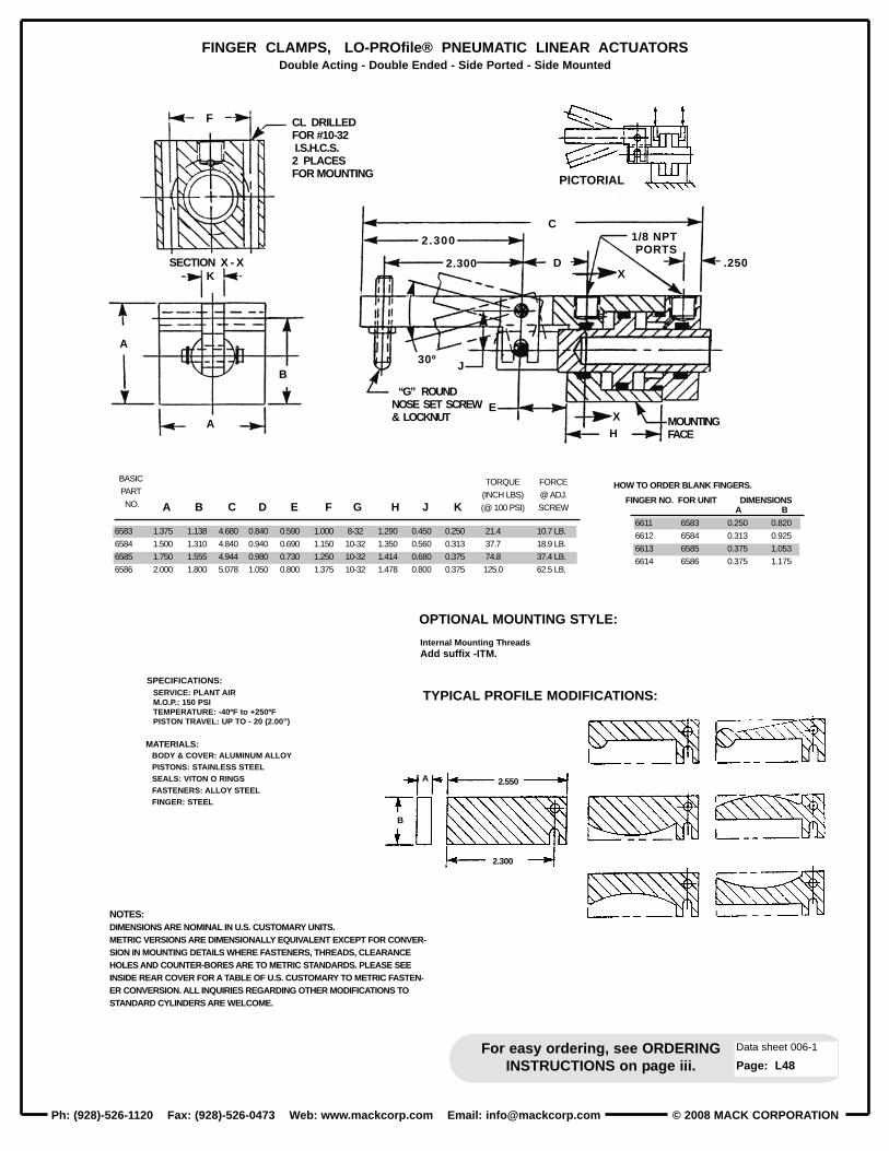
© 2008 MACK CORPORATIONPh: (928)-526-1120 Fax: (928)-526-0473 Web: www .mackcorp.com Email: [email protected]
For easy ordering, see ORDERINGINSTRUCTIONS on page iii.
Data sheet 006-1
Page: L48
FINGER CLAMPS, LO-PROfile® PNEUMA TIC LINEAR ACTUATORSDouble Acting - Double Ended - Side Ported - Side Mounted
F CL DRILLEDFOR #10-32I.S.H.C.S.2 PLACESFOR MOUNTING
SECTION X - XK
A
A
BASIC
PART
NO.
6583
6584
6585
6586
HOW TO ORDER BLANK FINGERS.
FINGER NO. FOR UNIT DIMENSIONS
6611
6612
6613
6614
6583
6584
6585
6586
0.250
0.313
0.375
0.375
0.820
0.925
1.053
1.175
A B
B
A 2.550
2.300
1.375
1.500
1.750
2.000
1.138
1.310
1.555
1.800
4.680
4.840
4.944
5.078
0.840
0.940
0.980
1.050
0.590
0.690
0.730
0.800
1.000
1.150
1.250
1.375
8-32
10-32
10-32
10-32
1.290
1.350
1.414
1.478
0.450
0.560
0.680
0.800
0.250
0.313
0.375
0.375
21.4
37.7
74.8
125.0
10.7 LB.
18.9 LB.
37.4 LB.
62.5 LB.
NOTES:DIMENSIONS ARE NOMINAL IN U.S. CUSTOMARY UNITS.METRIC VERSIONS ARE DIMENSIONALLY EQUIVALENT EXCEPT FOR CONVER-SION IN MOUNTING DETAILS WHERE FASTENERS, THREADS, CLEARANCEHOLES AND COUNTER-BORES ARE TO METRIC STANDARDS. PLEASE SEEINSIDE REAR COVER FOR A TABLE OF U.S. CUSTOMARY TO METRIC FASTEN-ER CONVERSION. ALL INQUIRIES REGARDING OTHER MODIFICATIONS TOSTANDARD CYLINDERS ARE WELCOME.
A B C D E F G H J K
TORQUE
(INCH LBS)
(@ 100 PSI)
FORCE
@ ADJ.
SCREW
B
C
D
J
E
H
X
X
2.300
2.300
30º
.250
1/8 NPTPORTS
MOUNTINGFACE
“G” ROUNDNOSE SET SCREW& LOCKNUT
PICTORIAL
SPECIFICATIONS:
MATERIALS:BODY & COVER: ALUMINUM ALLOYPISTONS: STAINLESS STEELSEALS: VIT ON O RINGSFASTENERS: ALLOY STEELFINGER: STEEL
SERVICE: PLANT AIRM.O.P.: 150 PSITEMPERATURE: -40ºF to +250ºFPISTON TRAVEL: UP TO - 20 (2.00”)
TYPICAL PROFILE MODIFICATIONS:
OPTIONAL MOUNTING STYLE:
Internal Mounting ThreadsAdd suffix -ITM.

© 2008 MACK CORPORATION Ph: (928)-526-1120 Fax: (928)-526-0473 Web: www .mackcorp.com Email: [email protected]
For easy ordering, see ORDERINGINSTRUCTIONS on page iii.
Data sheet 2007-7
Page: L49
SHORT STROKE PNEUMATIC CYLINDERS - LO-PROfile® SERIES B-SP-EMDouble Acting - Double Ended Pistons - Large Hollow Hubs - Side Ported - Face Mounted
NOTES:
Dimensions are nominal in U.S. Customary specifications.
METRIC CYLINDERS are dimensionaly equivalent withclearance holes, counterbores, threads & fasteners to metricspecifications. See inside rear cover for fastener conversiontable. There is no added cost for METRIC CYLINDERS.
An air/oil mist unit is recommended for internal lubrication.Where such unit s are not practical, SER VICE KITS includingseals & factory approved lubricant are available.
Cylinders may also be used in low pressure hydraulic serviceor with vacuum.
Inquiries regarding modifications to basic unit s are welcome.
B
B
B
# 10 - 32 INT. THD.G PLACESFOR MOUNTING
0.100PLUS
STROKE
1.500PLUS
STROKE
0.100
.625
SECT. Y-Y
1/8 NPTF PORTS2 PLACES
10-32 INT. THD.G PLACESFOR MOUNTING
B
F
F 2
A
XY
E
.875
SECT.X-X
E
XY
C
D
BASIC PARTNO.
6667- (-)
6668- (-)
6669- (-)
6670- (-)
6671- (-)
6672- (-)
6673- (-)
3.000
3.500
4.000
4.500
5.000
5.500
6.000
2.500
3.000
3.500
4.000
4.500
5.000
5.500
1.400
1.900
2.400
2.900
3.400
3.900
4.400
1.000
1.500
2.000
2.500
3.000
3.500
4.000
18
15
15
11.25
11.25
11.25
11.25
72
60
60
45
45
45
45
5
6
6
8
8
8
8
0.600
1.100
1.600
2.100
2.600
3.100
3.600
5
6
6
6
8
8
8
.021
.022
.0285
.038
.038
.046
.046
.026
.031
.039
.039
.039
.044
.044
1.800
2.300
2.800
3.300
3.800
4.300
4.800
1.005
1.320
1.634
1.948
2.262
2.576
2.891
100
132
163
195
226
258
289
O.D.
A
B.C.
BROD O.D.
C
ROD BORE
DDEG.
E
DEG.
FPLCS
G H J K LPISTON
O.D.
FORCE
@100 PSI
PISTON
AREA
SOLID HUB PISTON.Add suffix -SH.
D
DD
THRU HOLE WITH RETAINER GROOVE.Add suffix -RG .
K
L
0.100 ±.005
0.600±.010
PISTON WITH CLOSED END.Add suffix -CE.
0.600±.010
0.200±.005
10-32 INTERNALTHD. HOLES AT“J” LOCA TIONS.EVENLY SPACED.
H
FLANGE END WITH INTERNALTHREADS.Add suffix -FE.
MAX. BORE“D”
USER SPECIFIES THRU HOLE DIA.Add suffix -TH to p art no. followed by nominalhole dia. (±.005).
SPECIFICATIONS:
MATERIALS:BODY & COVER: ALUMINUM ALLOYPISTONS: ALUMINUM ALLOYSEALS: VIT ON O RINGSFASTENERS: ALLOY STEEL
SERVICE: PLANT AIRM.O.P.: 100 PSITEMPERATURE: -40ºF to +250ºFPISTON TRAVEL: UP TO - 20 (2.00”)
PISTON OPTIONS:
MATERIAL UPGRADES:
Stainless S teel PistonsAdd prefix S.
Stainless S teel CylindersAdd prefix SS.

© 2008 MACK CORPORATIONPh: (928)-526-1120 Fax: (928)-526-0473 Web: www .mackcorp.com Email: [email protected]
For easy ordering, see ORDERINGINSTRUCTIONS on page iii.
Data sheet 2002-3
Page: ACC-1
MANIFOLD - LO-PROfile® - 150 PSITo Facilitate Plumbing
1-1/2”
1/8-27 NPTFFEED PORTS
4 PLACES
1/4-18 NPTFFOR GAGE
2-1/2”
F-R-LUNIT
PLUG PORTSNOT USED
1/4-18 NPTFFOR GAGE
1/16-27 NPTFFEED PORTS4 PLACES
2”
1”
3/4”
1”
1/4”
1/4”
No. 4801 MANIFOLDMATERIAL, ALUM ALLOY(4) 1/8-27 FEED PORTS
MANIFOLD NO. 4801 PROVIDES EASY PLUMBINGFOR LO-PROfile® CYLINDERS WITH 1/8-27 NPTFPORTS.
MANIFOLD NO. 4806 IS IDENTICAL EXCEPT WITH1/16-27 NPTF PORTS FOR MINIATURE LO-PROfile®CYLINDERS.
No. 4806 MANIFOLDMATERIAL, ALUM ALLOY(4) 1/16-27 FEED PORTS
.219 DIA. HOLESFOR MOUNTING
1/4-18 NPTFINLET PORT
4 WAYVALVE
Plant Air
PLUG PORTSNOT USED
1/4-18 NPTFINLET PORTS
LO-PROfile®CYLINDERS
4801 MANIFOLDOR
4806 MANIFOLD

© 2008 MACK CORPORATION Ph: (928)-526-1120 Fax: (928)-526-0473 Web: www .mackcorp.com Email: [email protected]
APPENDIX A
TECH DATA - SHORT STROKE HYDRAULIC & PNEUMA TIC CYLINDERS
GENERAL CLASSIFICATIONSHORT STROKE CYLINDERS ARE DEFINED AS A FAMILY OF CYLINDERS WHEREPISTON STROKE IS A FRACTION OF THE PISTON DIAMETER. TECHNICALLYDEFINED AS S/D < 1.0.
INSTALLA TIONKEY CONSIDERATIONS FOR LONG SERVICE LIFE INCLUDE CAREFUL ALIGNMENTAT INSTALLATION AND MAINTAINING CLEAN FLUIDS. CYLINDERS SHOULD BECENTERED WITH THE THRUST LINE OF THE WORK LOAD WITHIN A FEW THOUSANDSOF AN INCH AND SQUARE WITHIN A FRACTION OF A DEGREE.
FORCE OUTPUTCYLINDER THRUST IS SIMPLY THE PRODUCT OF OPERATING PRESSURE (psi) TIMESNET PISTON AREA (sq.in.). REDUCTION IN THRUST FROM FRICTION WITHIN ACYLINDER CAN BE IGNORED EXCEPT FOR VERY SMALL PISTON AREAS OPERATINGAT LOW PRESSURE. THERE IS PHENOMENON CALLED “STICTION” (high breakwayfriction) WHEN CYLINDERS STAND IDLE FOR EXTENDED PERIODS. SEAL FRICTIONQUICKLY RETURNS TO MUCH LOWER LEVELS FOLLOWING THE FIRST FEW CYCLES.A PRACTICAL RULE OF THUMB IS TO SELECT A CYLINDER WITH OUTPUT WHICH ISSLIGHTLY HIGHER THAN REQUIRED TO OVERCOME THE LOAD.
CONTROL CIRCUITSDIRECTIONAL CONTROL VALVES ARE READILY AVAILABLE IN MANY CONFIGURATIONSFROM MANY SOURCES. STANDARD THREE WAY VALVES PROVIDE CONTROL FORSINGLE ACTING CYLINDERS WHILE FOUR WAY VALVES ARE USED FOR CONTROLLINGDOUBLE ACTING CYLINDERS. MANUALLY OPERATED VALVES ARE COMMON FOR WORKCLOSE AT HAND WHILE SOLENOID OPERATED VALVES ARE PREFERRED FOR CONTROLFROM A REMOTE LOCATION & FOR PROGRAMMING AS PART OF AN AUTOMATED PROCESS.
ADVANTAGESTHE OBVIOUS ADVANTAGE TO SHORT STROKE CYLINDERS IS COMPACTNESS. SHORTSTROKE CYLINDERS NOT ONLY REDUCE SIZE AND INITIAL COST OF FIXTURES ANDRELATED EQUIPMENT BUT PROVIDE ENERGY SAVINGS FOR THE LIFE OF THE PROJECT.RELATIVELY THICK CYLINDER WALLS WHICH PERMIT INTERNAL FLOW PASSAGES ARE ANOTHER ADVANTAGE. AN EXAMPLE IS A CONFIGURATION WITH END TREPANNED PORTSFOR POCKET MOUNTING WHERE FEED LINES ARE ELIMINATED IN THE WORK ZONE.
LIMITATIONSSHORT STROKE CYLINDERS CAN NOT TAKE LARGE SIDE LOADS AND MOMENTS FROM WITHIN THE CYLINDER STRUCTURE. THIS IS PARTICULARLY TRUE FOR SINGLE ENDEDVERSIONS. CYLINDERS WITH DOUBLE ENDED PISTONS WILL SUPPORT SIDE LOADSAND MOMENTS BETTER BECAUSE OF BEARING SURFACES AT BOTH ENDS. ELIMINATINGOR REDUCING SIDE LOADS AND MOMENTS TO A MINIMUM WITH THE USE OF EXTERNALGUIDES WILL EXTEND CYLINDER LIFE, REGARDLESS OF TYPE, SIZE AND STROKE.BASICALLY, HYDRAULIC & PNEUMATIC CYLINDERS ARE LINEAR FORCE DEVICES AND NOT INTENDED TO FUNCTION AS GUIDES.
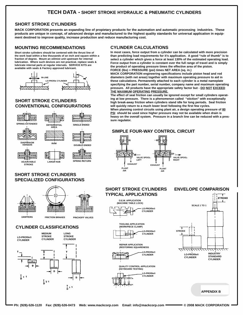
© 2008 MACK CORPORATIONPh: (928)-526-1120 Fax: (928)-526-0473 Web: www .mackcorp.com Email: [email protected]
APPENDIX B
TECH DATA - SHORT STROKE HYDRAULIC & PNEUMA TIC CYLINDERS
MACK CORPORATION present s an exp anding line of propiet ary product s for the automation and automatic processing industries. Theseproduct s are unique in concept, of advanced design and manufactured to the highest quality st andards for universal application in equip -ment destined to improve quality , increase production and reduce manufacturing cost.
Short stroke cylinders should be centered with the thrust line ofthe work load within a few thousands of an inch and square within afraction of degree. Mount an oil/mist unit up stream for internallubrication. Where such devices are not practical, replace seals &lubricate internal p arts at regular intervals. SER VICE KITS areavailable with seals & Factory approved lubricant.
CYLINDER CALCULA TIONSIn most cases, force output from a cylinder can be calculated with more precisionthan predicting load requirement s for it’ s application. A good “rule of thumb” is toselect a cylinder which gives a force at least 130% of the estimated operating load. Force output from a cylinder is const ant over the full range of travel and is simplythe product of operating pressure times the effective area of the piston. FORCE (lbs) = PRESSURE (p si) times NET AREA (sq. in.) MACK CORPORATION engineering specifications include piston head and roddiameters (with net areas) together with maximum operating pressure to aid inthese calculations. Permanently att ached to each cylinder is a met al nameplatespecifying the p art number , serial number , comp any name and maximum operatingpressure. All product s have the appropriate safety factor but - DO NOT EXCEEDTHE MAXIMUM OPERATING PRESSURE.The effect of seal friction can usually be ignored except for small cylinders operat -ing at low pressure. There is a phenomenon called “stiction” with exceptionallyhigh break-away friction when cylinders st and idle for long periods. Seal frictionwill quickly return to a much lower level following the first few cycles.When planning control circuit s using plant air , a design operating pressure of 80PSI should be used since higher pressure may not be available when drain isheavy on the overall system. Pressure in a branch line can be reduced with a pres -sure regulator .
IN-LINE
EXHAUST EXHAUST
PLANTAIR
PLANTAIR
LO-PROfile CYLINDER
VALVE SPOOL-LEFT
VALVE SPOOL-RIGHT
GRIPPERS
SPRING EXTENDED DIFFERENTIALAREA
SINGLE ENDED
DIAPHRAGMVERSION
RAMDOUBLE ENDED
ADJUSTABLESTROKE
LARGE HUB SPRING RETURN
FRICTION BRAKES PINCHOFF VALVES
O.E.M. APPLICATION(MACHINE TABLE LOCK)
TOOLING APPLICATION(WORKPIECE CLAMP)
REPAIR APPLICATION(RESTORING SQUARENESS
QUALITY CONTROL APPLICATION(KEYBOARD TESTING)
LO-PROfile®CYLINDER
LO-PROfile®CYLINDER
LO-PROfile®CYLINDER
LO-PROfile®CYLINDER
LO-PROfile®CYLINDER
LO-PROfile®CYLINDER
INDUSTRYSTANDARDCYLINDER
MEDIUMSTROKECYLINDER
LONGSTROKECYLINDER
STROKE
SCALE 1 TO 1
SHORT STROKE CYLINDERS
MOUNTING RECOMMENDATIONS
CYLINDER CLASSIFICA TIONS
ENVELOPE COMPARISONSHORT STROKE CYLINDERSTYPICAL APPLICATIONS
SHORT STROKE CYLINDERSCONVENTIONAL CONFIGURATIONS
SHORT STROKE CYLINDERSSPECIALIZED CONFIGURATIONS
SIMPLE FOUR-WAY CONTROL CIRCUIT

© 2008 MACK CORPORATION Ph: (928)-526-1120 Fax: (928)-526-0473 Web: www .mackcorp.com Email: [email protected]
REQUEST FOR QUOTATION (short form)
FOR A QUICK QUOTATION FOR YOUR SHORT STROKE CYLINDER REQUIREMENT-PLEASE USETHIS FORM, INCLUDE A ROUGH SKETCH, FILL IN YOUR SPECIFICATIONS, AND FAX TO MACKCORPORATION ENGINEERING DEPARTMENT (FAX # (928)-526-0473). MANY CONFIGURATIONS,NOT IN OUR CURRENT CATALOG, CAN BE MADE AVAILABLE AT REASONABLE COST USINGSTANDARD COMPONENTS AND EXISTING TOOLING.
SKETCH HERE-
ENGINEERING UNITS: U.S. CUSTOMARY SPECIFICATIONS UNLESS OTHERWISE REQUESTED.SERVICE: HYDRAULIC OIL_____, PLANT AIR_____, OTHER___________________(please specify)MAXIMUM OPERATING PRESSURE: 150PSI____,1500PSI____,3000PSI____ OTHER_________EXTENDING THRUST: ________FORCE (in.lbs.) REQUIRED AT______PSI.RETRACTING THRUST: ________FORCE (in.lbs.) REQUIRED AT______PSI.PISTON STROKE: _______(to nearest 1/10 [0.100] inch with 4.000 inches for maximum stroke)PISTON ROD DIAMETER: _____________PISTON ROD THREAD: INTERNAL____ EXTERNAL___ PIST ON ROD THREAD SIZE________WRENCH FLATS: YES___ NO___ROD SEAL TYPE: “O” RINGS____ LIP SEALS____OPERATING TEMPERATURE: +200 to -30 deg. F ., OTHER_____________SIDE PORTS: 1/8NPTF___, SAE-4___, 1/8BSPT___, 1/8BSPP___, M10X1___, 1/16NPTF___, 10-32___OPTIONAL PORTING: END TREPANNED PORTED FOR POCKET MOUNTING________ESTIMATED DUTY SERVICE: CYCLES PER HOUR________MATERIALS; (if special) BODY______________, COVER______________, PIST ON________________SPECIAL REQUIREMENTS___________________________________________________________________________________________________________________________________________________________-----------------------------------------------------------------------------------------------------------------------------------------------------------------
YOUR NAME:__________________________________________ TITLE:______________________________COMPANY NAME:_________________________________________STREET ADDRESS:_________________________________________________________________CITY:___________________________ STATE:____________________ ZIP CODE:__________________PHONE NUMBER:_______________________ FAX NUMBER:______________________EMAIL ADDRESS:_______________________ WEB SITE:_________________________
APPENDIX C

© 2008 MACK CORPORATIONPh: (928)-526-1120 Fax: (928)-526-0473 Web: www .mackcorp.com Email: [email protected]

© 2008 MACK CORPORATION Ph: (928)-526-1120 Fax: (928)-526-0473 Web: www .mackcorp.com Email: [email protected]
PART NUMBER SEARCH
626................6265..............627................6275..............628................6285..............629................630................6305..............631................6315..............632................6325..............633................
802................8025..............803................8035..............804................8045..............805................806................8065..............807................8075..............808................8085..............809................
1007..............10075............1008..............10085............1009..............10095............1010..............1011..............10115............1012..............10125............1013..............10135............1014..............1015..............10155............1016..............10165............1017..............10175............1018..............1019..............10195............1020..............10205............1021..............10215............1022..............
1031..............1032..............1033..............1034..............
1044..............1045..............1046..............1047..............
1515151515151516161616161616
1717171717171718181818181818
1111111222222233333334444444
7777
8888
BASIC PART NO.
PAGE NO.
1082..............1083..............10835............1084..............10845............1085..............10855............1086..............1087..............10875............1088..............10885............1089..............10895............
1593..............1594..............1595..............1596..............15965............1597..............1598..............15985............1599..............15995............1600..............16005............1601..............
S1705............S1706............S1707............S1708............S17085..........S1709............S1710............S17105..........S1711............S17115..........S1712............S17125..........S1713............
S1866............S18665..........S1867............S18675..........S1868............S18685..........S1869............S1870............S18705..........S1871............S18715..........S1872............S18725..........S1873............
1909..............1910..............1911..............1912..............
S1915............S1916............S1917............S1918............S1919............S1920............S1921............S1922............
191919191919195555555
12121212121221212121212121
13131313131322222222222222
666666620202020202020
43434444
1414141414141414
BASIC PART NO.
PAGE NO.
S1923............S1924............S1925............S1926............S1927............S1928............S1929............S1930............S1931............S1932............S1933............S1934............S1935............S1936............S1937............S1938............S1939............S1940............S1941............S1942............S1943............S1944............S1945............S1946............S1947............S1948............S1949............S1950............S1951............S1952............S1953............S1954............
S2134............S2135............S2136............S2137............S2138............S2139............S2140............S2141............S2142............S2143............S2144............S2145............
S2300............S2301............S2302............S2303............S2304............S2305............
M5201...........M5202...........M5203...........M5204...........M5205...........M5206...........M5207...........M5208...........M5209...........M5210...........M5211...........M5212...........M5213...........M5214...........M5215...........M5216...........M5217...........M5218...........
1414141414141414141414141414141414141414141414141414141414141414
111111111111101010101010
999999
343434343434353535353535363636363636
BASIC PART NO.
PAGE NO.
5701..............5702..............5703..............5704..............
5709..............5710..............5711..............5712..............
6000..............6001..............6002..............6003..............6004..............6005..............6006..............6007..............6008..............6009..............6010..............6011..............6012..............6013..............6014..............6015..............6016..............6017..............6018..............6019..............6020..............6021..............6022..............6023..............6024..............6025..............6026..............6027..............
6035..............6036..............6037..............6038..............6039..............6040..............6041..............
6086..............6087..............6088..............6089..............6090..............6091..............6092..............6093..............
S6200............S6201............S6203............
S6240............S6241............S6242............S6243............S6244............
S6245............S6246............S6247............S6248............S6249............S6251............S6252............
30303030
31313131
24242424242424232323232323232525252525252526262626262626
27272727272727
2828282829292929
373737
3232323232
33333333333838
BASIC PART NO.
PAGE NO.
S6253............S6254............
S6264............S6265............S6266............S6267............
6405..............6406..............6407..............6408..............6409..............6410..............6411..............6412..............6413..............6414..............6415..............6416..............6417..............6418..............6419..............6420..............6421..............6422..............6423..............6424..............6425..............
S6509............S6510............S6511............S6512............S6513............S6514............S6515............S6516............S6517............S6518............S6519............S6520............
6583..............6584..............6585..............6586..............
6667..............6668..............6669..............6670..............6671..............6672..............6673..............
3838
39393939
404040404040404141414141414142424242424242
454545454646464647474747
48484848
49494949494949
BASICPART NO.
PAGENO.

© 2008 MACK CORPORATIONPh: (928)-526-1120 Fax: (928)-526-0473 Web: www .mackcorp.com Email: [email protected]
HOW TO ORDER METRIC MOUNTING OPTIONS:ADD THE PREFIX “M” TO A PRODUCT NUMBER AND A SUFFIX TO INDICATE PISTON TRAVEL IN MILLIMETERS FOLLOWED. BY THE LIP SEAL SUFFIX.
EXAMPLE: M -S3513- 20mm - LS
METRIC MOUNTING OPTION:ALL U.S. CUSTOMARY PRODUCTS IN THIS CATALOG ARE READILY AVAILABLE IN MODIFIED METRIC CONFIGURA TIONS WHERE MOUNTING DETAILS CONFORM TO METRIC SPECIFICATIONS BY CONVERTING THREADED HOLES, CLEARANCE HOLES, COUNTER-BORES, AND FASTENERS TO METRIC SIZES LISTED BELOW : THERE IS NO ADDED COST.
THREAD CONVERSION - U.S. STD. TO METRICU.S. Thd. #2-56 #4-40 #6-32 #8-32 #10-32 1/4-28 5/16-24 3/8-24 7/16-20 1/2-20 5/8-18 3/4-16 1-14 1 1/4-12Metric Thd. M2x0.4 M3x0.5 M3x0.5 M4x0.7 M5x0.8 M6x1.0 M8x1.25 M10x1.5 M10x1.5 M12x1.75 M16x2.0 M20x2.5 M24x3.0 M30x3.5
Piston T ravel Conversion - INCHES to Millimeters
PISTON TRAVEL IN MILLIMETERSPRODUCT NUMBER FROM THE TABLE
METRIC PREFIX
DashNo.
U.S.Customary
(Inches)
METRICSystem
(mm)
-1-2-3-4-5-6-7-8-9
-10
0.1000.2000.3000.4000.5000.6000.7000.8000.9001.000
2.55.07.5
10.012.515.017.520.022.525.0
DashNo.
U.S.Customary
(Inches)
METRICSystem
(mm)
-11-12-13-14-15-16-17-18-19-20
1.1001.2001.3001.4001.5001.6001.7001.8001.9002.000
27.530.032.535.037.540.042.545.047.550.0
DashNo.
U.S.Customary
(Inches)
METRICSystem
(mm)
-21-22-23-24-25-26-27-28-29-30
2.1002.2002.3002.4002.5002.6002.7002.8002.9003.000
52.555.057.560.062.565.067.570.072.575.0
DashNo.
U.S.Customary
(Inches)
METRICSystem
(mm)
-31-32-33-34-35-36-37-38-39-40
3.1003.2003.3003.4003.5003.6003.7003.8003.9004.000
77.580.082.585.087.590.092.595.097.5
100.0
Terms:Discount s:Revisions:Short ages:Returns:
Shipping Method:Minimum Orders:Foreign Orders:
Past Due Account s:Liability:Product Changes:
GENERAL SALES CONDITIONS30 days net, to approved account s. F.O.B. Flagst aff, AZDiscount s apply to larger quantities of the same p art number shipped as a single lot.Orders in process may be revised by mutual agreement and are subject to reasonable compensation.Any claim for short age in shipment must be made within 30 days from receipt of material.Returns due to requirement change or errors in ordering must have factory approval.A charge of 25% will be made for administrative cost, re-inspection, accept ance testing and re-stocking.No return credit is allowed on modified unit s, on unit s made to special order , on unit s having been placedin service or on unit s which have been in the hands of a customer for over 90 days from the invoice date.Where shipping instructions are not specified, shipping will be made according to our best judgement.$30.00 for domestic orders. $100.00 for international orders.Foreign orders will be p aid in United S tates funds. A surcharge of $30.00 will be added to cover costof the additional administrative and clerical work.Interest of 1 1/2% per month will be added to p ast due account s.Product liability is limited to replacement of the p art.Right is reserved to change engineering specifications.
WARRANTYMack Corporation warrant s to the original equipment manufacturers and industrial users of it's product s that each new product manufactured andsupplied by Mack Corporation shall be free from defect s in material and workmanship. Mack Corporation's obligation under this warranty is limited tofurnishing, without additional charge, a replacement or , at it s option, rep airing or issuing credit for any product which shall within 90 days from thedate of sale be returned freight prep aid to the factory and which upon inspection is determined by Mack Corporation to be defective in material orworkmanship. W ritten authorization must be obt ained from Mack Corporation prior to return of a product and complete information as to operatingconditions, inst allation and application must accomp any any product returned for inspection. The provisions of this warranty shall not apply to anyMack Corporation product which has been subjected to misuse, improper inst allation or operating conditions, or which has been rep aired or alteredif such rep air or alteration in the judgment of Mack Corporation would adversely affect performance or safety of the product.
This warranty is in lieu of all other warranties, expressed or implied, including any implied warranty of merchant ability or fitness for a p articularpurpose and is also in lieu of all other obligations or liabilities on the p art of Mack Corporation, including any obligation or liability arising from contract, tort, or otherwise for damages whether direct, indirect or consequential. There are no other warranties, expressed or implied, made by MackCorporation except the warranty against defect s in materials or workmanship set forth and Mack Corporation neither assumes nor authorizes anyother person or firm to assume for it any obligation or liability in connection with Mack Corporation product s.
LIP SEAL
